closed loop traffic signal controller - · pdf fileclosed loop traffic signal controller ......
TRANSCRIPT
International Journal of Scientific and Research Publications, Volume 5, Issue 2, February 2015 1 ISSN 2250-3153
www.ijsrp.org
Closed loop traffic signal controller
Reshmi Banerjee
Electrical Engineering Department, Guru Nanak Institute of Technology
Abstract- In our daily life traffic signal controller plays a vital
role in channeling the vehicles from one corner of the city to the
other. This system not only maintains a systematic approach in
terms of “vehicle management” but also reduces accidents and
rushes in peak hours. The disadvantage of open loop system is
poor “time management”. So the poor time management of open
loop system is rectified by closed loop system, keeping in mind
both efficiency and cost of the system.
Index Terms- Closed loop system, Open loop, Time
management, Traffic signal controller.
I. INTRODUCTION
n today’s world time is very - very important and often in
open loop system we lose much of our precious time. Suppose
a road is programmed to be open for 1 minute and it is seen that
after the initial passing of vehicles for 10 seconds there is no
other vehicle within 20 meters mark. As a result of which when
the next vehicle comes, we have already lost important time.
Benefits of traffic signal controller : i) Increasing the traffic
handling capacity of roads. ii) Reducing collisions, both
vehicular and pedestrian. Encourages travel within the speed
limit to meet green lights. iii) Reducing unnecessary stopping
and starting of traffic – this in turn reduces fuel consumption, air
pollution, noise and vehicle wear and tear. iv) Improve journey
time. v) Reducing driver frustration and ‘road rage’.
The IC555 timer in astable mode is used here for developing
the 60 seconds and 8 seconds delay. The basic block diagram is
given below:
LDR depends for its operation on the inner photoelectric
effect. The incident light controls the reverse current of a
photodiode.
The laser receiver consists of a darlington pair,a LDR,a
variable resistance and a fixed resistance.
Research Elaborations – The basic idea behind closed loop
system is efficient time management in addition to good vehicle
management. In open loop system there was no feedback for
determining the density of vehicle; this major drawback is
eliminated in design of closed loop system.
Here the control mechanism will open a specific sequence of
road for suppose t1 time. Within this t1 time we will be
receiving a signal from the road depending on vehicle density.
Whenever the density is low / nil and the signal is fed back to the
controller for a time t2 (t2 < < t1), it will automatically change to
the next sequence of traffic control. Thus efficient time
management is achieved by closed loop system.
I

International Journal of Scientific and Research Publications, Volume 5, Issue 2, February 2015 2
ISSN 2250-3153
www.ijsrp.org
We are using laser mechanism for presence / absence of
vehicle at the junction of roads. The following figure will
simplify the idea :
Here only four lanes B, D, F and H are responsible for
release of vehicles, so we are placing laser mechanism at the
head of each lane. Whenever there is a car at the head of these
lanes, the laser beam will be obstructed and digitally this is 0.
Whenever the laser beam falls on the receiver it is 1 giving the
idea that the immediate vehicle is behind the laser mechanism.
Then the problem arises, how to determine the density of
road? Since when laser receiver is 1 it implies the immediate
vehicle is behind the laser mechanism but the next problem is the
distance between laser and immediate vehicle. For this we are
using a delay, by that it is determined that the density on a road is
high or low.
We are using the real time setting for the traffic signal
controller. So whenever a road sequence starts it will primarily
be opened for 1 minute (60 seconds). Again in order to determine
the low density of a road we apply the idea that whenever the
laser receiver is 1 and the immediate vehicle is behind 20 meters
mark from the laser a second delay will complete its time period
and eventually resets the first delay (60 seconds) and changes on
to the next sequence. This action will stop the vehicle behind 20
meters mark from crossing the laser. We have seen practically
that a vehicle crossing a four way junction of roads always keep
the speedometer at 10 km per hour. So to cross a 20 meters mark
a car requires round about 8 seconds. If we set the second delay
at 8 seconds so that it can automatically stop the vehicles, which
are behind the 20 meters mark.
Both the delays of 60 seconds and 8 seconds will work
synchronously and each of them can change the sequence of
roads whenever their cycle is completed. The general flow of
traffic in all possible direction are shown below :
For figure 1, 4, 5 and 8 the working of both the delays will
follow the following chart :

International Journal of Scientific and Research Publications, Volume 5, Issue 2, February 2015 3
ISSN 2250-3153
www.ijsrp.org
For figure 2, 3, 6 and 7 as both roads are working
simultaneously then the transition of sequence will occur if delay
– 1 (60 seconds) has completed its cycle or delay – 2 (8 seconds)
of both the roads have completed their cycles.
Here we are designing two delays (60 seconds and 8
seconds) with IC555 and couple it to the 3 – bit binary counter.
But here a problem arises, how we are going to synchronize the
delays? As for road sequence 1, 4, 5 and 8 both the delays are
ORed i.e. whenever one delay completes its time period the 3-bit
counter changes to the next state but when the road sequence 2,
3, 6 and 7 are in operation both the 8 seconds delays of two roads
are ANDed i.e. they can change the sequence only when density
of vehicle in both roads are low; the ANDed operation in finally
ORed to the 60 seconds delay. Simply we can show :
SEQUENCE = > [DELAY – 1] OR [DELAY – 2]
(I,4,5,8)
SEQUENCE = > [DELAY – 1] OR [DELAY – 2 AND DELAY
– 2 ]
(2,3,6,7)
Here two delay – 2 are represented for road B and F
(sequence 2,3) and D and H (sequence 6, 7).
For convenient operation we are ANDing the output of laser
receiver of path B & F and also of path D & H. Again we are
ANDing both the outputs of the previous two AND gates and the
output of the 3rd
AND gate is given to 8 seconds delay at pin 4
(reset pin). From pin 3 (output terminal) we give one input to a
OR gate and the same input is being given to 60 seconds delay at
pin 4 to reset it. Likewise from pin 3 of 60 seconds delay we give
input to the OR gate and the same being given to pin 4 of 8
seconds delay. Thus 8 seconds delay will be reset whenever 60
seconds delay completes. The output of the OR gate is given to a
3 – bit binary counter which generates 8 states and works on the
same principle as of a open loop system. For closed loop system
both 8 seconds and 60 seconds delays are important, as whenever
one completes its time period we will go to the next sequence.
Both delays are reset the other one for a smooth operation. Here
one important fact is that the 8 seconds delay forcefully changes
the sequence when we are in a 60 seconds slot.
In laser operation for determining density of road one
criterion to be fulfilled. The criterion is that when a certain road
is closed, the first vehicle should stop behind the laser
mechanism, which will be marked on the road. Thus, when a
road is closed we will be “high” value from laser receiver and to
AND gates. This satisfies the criteria that the road, which is
open, can only trigger the 8 seconds delay when the laser
receiver is “high” i.e. no vehicle.

International Journal of Scientific and Research Publications, Volume 5, Issue 2, February 2015 4
ISSN 2250-3153
www.ijsrp.org
The laser circuit is giving a high output when laser falls on
to the LDR whereas the output is low if the laser is obstructed. In
the first case vehicle is absent whereas vehicle is present in the
second case. Now for synchronizing the two delays we are
considering three cases :
i) 60 second is on, 8 second is off, 60 second changes the
state : 8 second is only off, when vehicle is present in between
laser transmitter and laser receiver i.e. the laser output terminal is
low. So the 3 input AND gate output terminal is low, making 8
seconds delay off. But the NOT gate at 8 seconds output terminal
will be giving high output and for that reason we are giving the
input terminal of pin 4 of 8 seconds delay to pin 14 of NOT gate.
This will make the IC7404 to be at ground potential and gives
low output, which is fed back to XOR gate and then given to pin
4 of 60 seconds delay. This will help the 60 seconds delay to
remain ON and changes the state after its time period.
ii) 60 second is on,8 second starts and stops within 8
second,60 second changes the state: Here the 3-input AND gate
output terminal is high and starts the 8 second delay and thus the
NOT gate is getting its required +V(CC).But still the output
terminal of NOT gate is low and within 8 second slot the delay
stops(due to presence of vehicle).Thus the NOT gate is at ground
potential and still its output is low. Thus 60 second delay is ON
and changes the state.
iii) 60 second is on,8 second starts and completes,8 second
changes the state: If 8 second delay completes its time period
the output of NOT gate is high, thus the 60 second delay is reset
as both XOR input terminals are high. The 8 second delay
changes the state. This sequence only proves that the density of
road is low and there is no vehicle within 20 meters mark.
International Journal of Scientific and Research Publications, Volume 5, Issue 2, February 2015 5
ISSN 2250-3153
www.ijsrp.org
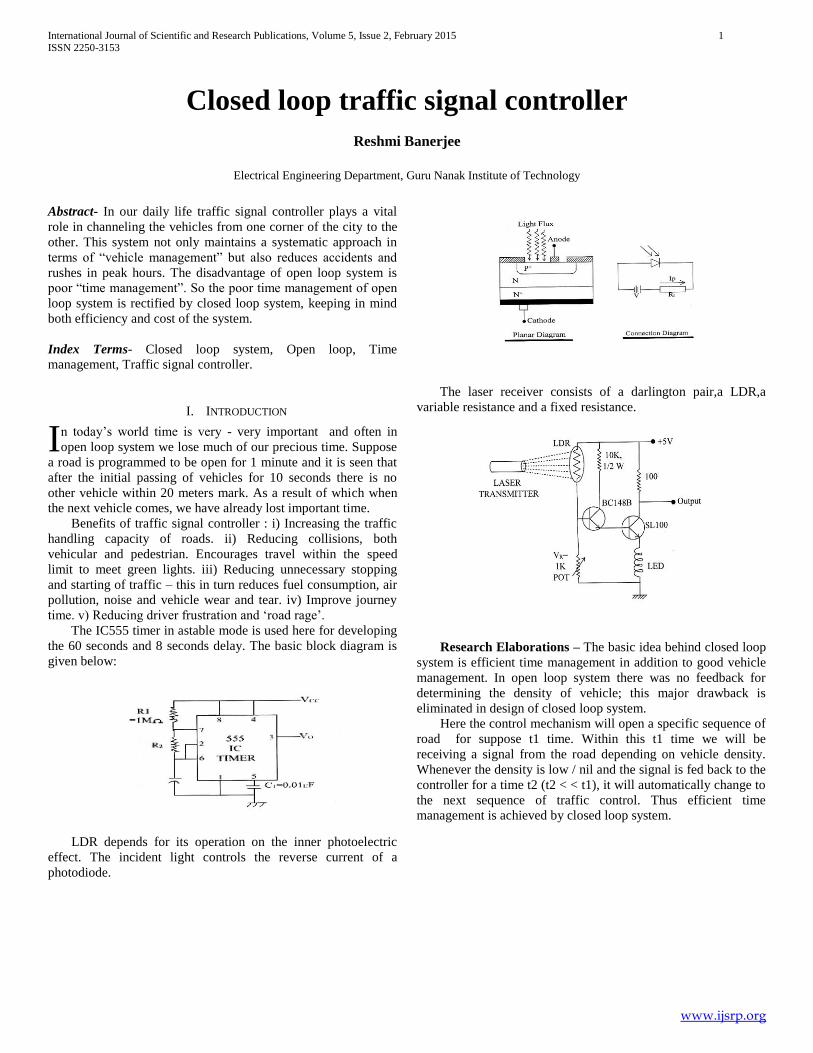
Fig. 3 : Operation of 3 – bit binary counter
For giving practical low and high values to pin 4 of both
delays relays have been used, which are operated by a transistor.
The relay operated as a NOT gate.
Whenever a particular sequence (overall 8 sequence) of road
opens, the 60 seconds delay starts on its own. If traffic density is
high it will continue its time period upto 60 seconds and then
gives a pulse to the 3-bit binary counter to change its state.
The roads which are closed will give a “high” output to the
ANDed input terminal and the road/roads which are open will
give a “low” output if density of road is high. When density of
road is low it will give a “high” output and thus the ANDed
combination will only work then and starts the 8 seconds delay.
The 8 seconds delay can be reset whenever the output of the
specific road is “low”.
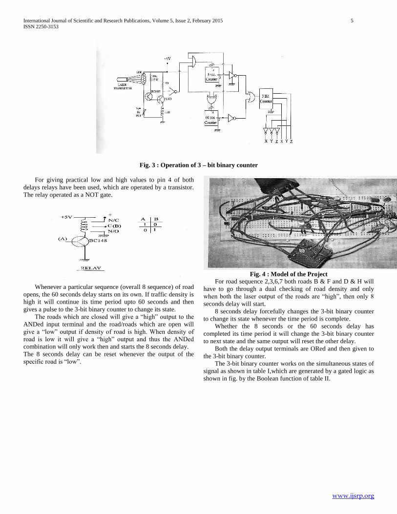
Fig. 4 : Model of the Project
For road sequence 2,3,6,7 both roads B & F and D & H will
have to go through a dual checking of road density and only
when both the laser output of the roads are “high”, then only 8
seconds delay will start.
8 seconds delay forcefully changes the 3-bit binary counter
to change its state whenever the time period is complete.
Whether the 8 seconds or the 60 seconds delay has
completed its time period it will change the 3-bit binary counter
to next state and the same output will reset the other delay.
Both the delay output terminals are ORed and then given to
the 3-bit binary counter.
The 3-bit binary counter works on the simultaneous states of
signal as shown in table I,which are generated by a gated logic as
shown in fig. by the Boolean function of table II.

International Journal of Scientific and Research Publications, Volume 5, Issue 2, February 2015 6
ISSN 2250-3153
www.ijsrp.org
II. CONCLUSIONS
i) The system will never fail as there is a separate 60 seconds
delay which only depends on the change of state of the 3-bit
binary counter. So even if the laser mechanism or the 8 seconds
delay fails to operate, the 60 seconds delay will continue to
operate and thus the closed loop system converts into an open
loop system and reduces all chances of accidents.
ii) Here we only apply one special condition in the road.
From head of a road there will be zebra crossing, then the laser
mechanism and finally the vehicle stopping mark. The three
should not collide with each other.
iii) The above condition can hold good at all times when we
are implanting two traffic police at the junction of the roads. Also
fencing at the side of the roads is necessary upto the laser
mechanism.
REFERENCES
[1] I.J. Nagrath, “Control Systems Engineering”, New Age International.
[2] S. Hasan Saeed, “Control Systems”, SK Kataria & Sons.
[3] Forrest M. Mims iii, “Timer,Op Amp & Optoelectronic Circuits & Projects”, Master Publishing Inc.
[4] Anil K. Maini, “Digital Electronics:Principles,Devices and Applications”, Wiley.
[5] Nair B. Somanathan, “Digital Electronics and Logic Design”, PHI.
[6] Anand Kumar, “Fundamentals of Digital Circuits”, PHI.
AUTHORS
First Author – Reshmi Banerjee, M.Tech., Guru Nanak Institute
of Technology, e-mail : [email protected], Alternate
e-mail : [email protected], Contract No. 09830319497.