clte-mw laminates data sheet
TRANSCRIPT

100 S. Roosevelt Avenue, Chandler, AZ 85226Tel: 480-961-1382 Fax: 480-961-4533 www.rogerscorp.com
Page 1 of 4
CLTE-MW™ Laminates CLTE-MW™ laminates are ceramic filled, woven glass reinforced PTFE composites. CLTE-MW laminates were developed to provide a cost effective, high performance material for the circuit designer. This unique laminate system is well suited for applications that have limitations in thickness due to either physical or electrical constraints. The seven available thickness options from 3 mils to 10 mils ensure that ideal signal to ground spacing exists for today’s 5G and other millimeter wave designs. In addition, a variety of copper foil options are available including rolled, reverse treated ED, and standard ED. Resistive foil and metal plate options are also available upon request.
The CLTE-MW laminates are reinforced with spread glass, which along with a high filler loading help minimize the high frequency glass weave effects on electromagnetic wave propagation. The woven glass reinforcement also provides excellent dimensional stability. Other key features of the laminate include low z-axis CTE (30ppm/°C) for excellent plated through hole reliability, a low loss tangent of 0.0015 at 10 GHz to enable low loss designs, and low moisture absorption of 0.03% to ensure stable performance in a range of operating environments. Thermal conductivity of 0.42 W/(m.K) enables heat dissipation in aggressive designs along with a high dielectric strength of 630 V/mil to ensure good z-axis insulation between conductor layers. The UL94 V-0 flammability rating enables the use of CLTE-MW laminates in commercial applications.
CLTE-MW laminates are well suited for a range of applications including Amplifiers, Antennas, Baluns, Couplers and Filters. Applicable markets range from Commercial and Consumer to Defense and Aerospace.
Features and Benefits:
Excellent Dimensional Stability
• Critical for Registration of Small Circuit Features
Low X, Y & Z-axis CTE
• Reliable Mechanical Performance under Thermally Challenging Environments
Low Loss Tangent
• Low Circuit Losses
Available in thicknesses from 3-10mils
• Suitable for very high frequency applications
Typical Applications:
• Commercial Communications and Avionics
• Military/ Aerospace Applications • Microwave Feed Networks• Phase Sensitive Electronic
Structures• Satellite Communication
Systems• Passive Components (couplers,
filters & baluns)
Data Sheet

100 S. Roosevelt Avenue, Chandler, AZ 85226Tel: 480-961-1382 Fax: 480-961-4533 www.rogerscorp.com
Page 2 of 4
CLTE-MWProperty
Typical Value(1) Units Test Conditions Test Method
Electrical Properties
Dielectric Constant, (er) (2) 2.94 to 3.02 ±
0.04 - 23C @ 50% RH 10 GHz IPC TM-650 2.5.5.5
Dielectric Constant (design) (2) 3.03 to 3.10 C-24/23/50 8-40 GHzMicrostrip
Differential Phase Length
Dissipation Factor 0.0015 - 23C @ 50% RH 10 GHz IPC TM-650 2.5.5.5
Thermal Coefficient of Dielectric Constant -35 ppm/°C 0 to 100°C 10GHz IPC TM-650 2.5.5.5
Volume Resistivity 1.3 x 10⁷ Mohm-cm C-96/35/90 IPC TM-650 2.5.17.1
Surface Resistivity 2.5 x 10⁶Mohm C-96/35/90 IPC TM-650
2.5.17.1
Electrical Strength (dielectric strength) 630 V/mil IPC TM-650 2.5.6.2
Dielectric Breakdown 44 kV D-48/50 X/Y direction IPC TM-650 2.5.6
Comparative Tracking Index 600V/ PLC 0 class/volts C-40/23/50 UL-746A, ASTM D6054
Thermal Properties
Decomposition Temperature (Td) 500 °C 2hrs @ 105°C 5% Weight Loss IPC TM-650 2.3.40
Coefficient of Thermal Expansion 8 X/Y
ppm/˚C -55°C to 288°C IPC TM-650 2.4.4130 Z
Thermal Conductivity 0.42 W/(m.K) Z direction ASTM D5470
Time to Delamination >60 minutes as-received 288°C IPC TM-650 2.4.24.1
Mechanical Properties
Copper Peel Strength after Thermal Stress
1.1(6.0)
N/mm (lbs/in) 10s @288°C 35 μm foil IPC TM-650 2.4.8
Flexural Strength MDCMD
113 (16.4)99 (14.4) MPa (ksi ) 25C +/- 3C ASTM D790
Tensile Strength MDCMD
83 (12.0)80 (11.6) MPa (ksi ) 23C/50RH ASTM D3039/
D3039-14
Flex Modulus MDCMD
6468 (938.1)6360 (922.4) MPa (ksi ) 25C +/- 3C IPC-TM-650 Test
Method 2.4.4
Dimensional Stability (MD/CMD) 0.22/0.22 mil/inch after etch + bake IPC-TM-650 2.4.39a
Physical Properties
Flammability V-0 - - UL94
Moisture Absorption 0.03 % E1/105 +D48/50 IPC TM-650 2.6.2.1
Density 2.1 g/cm3 C-24/23/50 ASTM D792
Specific Heat Capacity 0.93 J/g°K 2 hours at 105°C ASTM E2716
Nasa Outgassing 0.03/<0.01 % 24 hours at 125°C TML/CVCM ASTM E595
(1) Typical values are a representation of an average value for the population of the property. For specification values contact Rogers Corp.(2) See Table 1 for more detailed design information

100 S. Roosevelt Avenue, Chandler, AZ 85226Tel: 480-961-1382 Fax: 480-961-4533 www.rogerscorp.com
Page 3 of 4
Thickness (mils) Process Dk (10 GHz) Design Dk (AH/AH)
3 2.94 3.10
4 2.97 3.08
5 2.96 3.07
6 3.02 3.07
7 3.00 3.06
8 3.01 3.05
10 3.00 3.03Table 1. Process and Design Dk data for CLTE-MW Laminate
Figure 1. Microstrip Differential Phase Length Method, Dk vs Frequency
Figure 2. Microstrip Insertion Loss, Differential Length Method
The information in this data sheet is intended to assist you in designing with Rogers’ circuit materials. It is not intended to and does not create any warranties express or implied, including any warranty of merchantability or fitness for a particular purpose or that the results shown on this data sheet will be achieved by a user for a particular purpose. The user should determine the suitability of Rogers’ circuit materials for each application.
The Rogers’ logo, CLTE-MW and Helping power, protect, connect our world are trademarks of Rogers Corporation or one of its subsidiaries.© 2021 Rogers Corporation, Printed in U.S.A., All rights reserved. Revised 1512 041321 PUB# 92-189
100 S. Roosevelt Avenue, Chandler, AZ 85226Tel: 480-961-1382 Fax: 480-961-4533 www.rogerscorp.com
Page 4 of 4
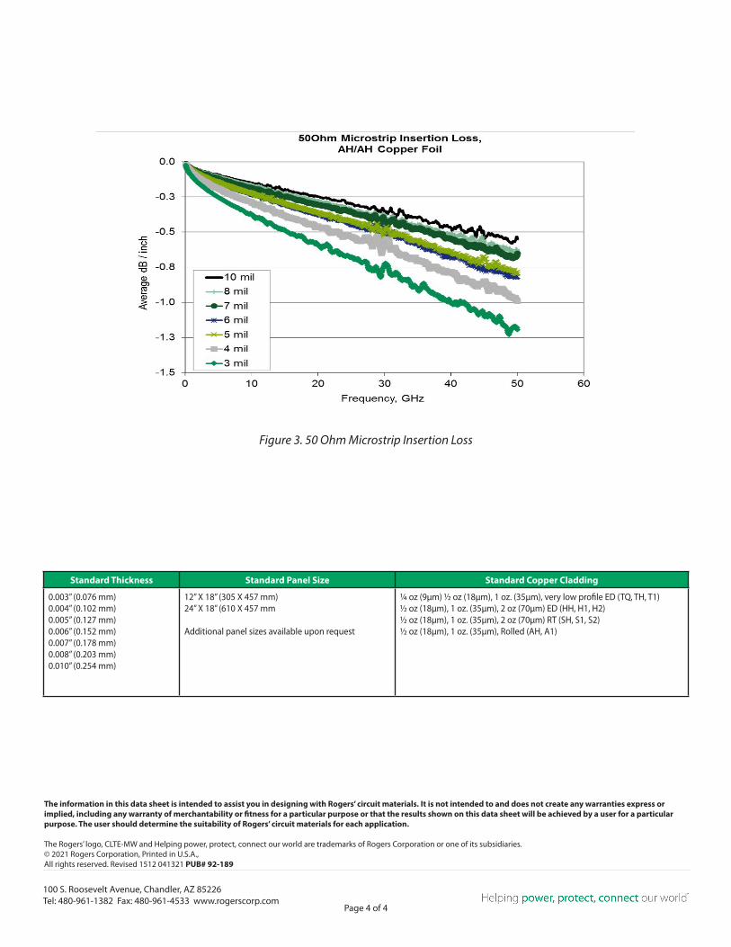
Figure 3. 50 Ohm Microstrip Insertion Loss
Standard Thickness Standard Panel Size Standard Copper Cladding
0.003” (0.076 mm)0.004” (0.102 mm)0.005” (0.127 mm)0.006” (0.152 mm)0.007” (0.178 mm)0.008” (0.203 mm)0.010” (0.254 mm)
12” X 18” (305 X 457 mm)24” X 18” (610 X 457 mm
Additional panel sizes available upon request
1/4 oz (9μm) ½ oz (18μm), 1 oz. (35μm), very low profile ED (TQ, TH, T1)½ oz (18μm), 1 oz. (35μm), 2 oz (70μm) ED (HH, H1, H2)½ oz (18μm), 1 oz. (35μm), 2 oz (70μm) RT (SH, S1, S2)½ oz (18μm), 1 oz. (35μm), Rolled (AH, A1)