club car engine drivetrain repair rebuild
DESCRIPTION
Club Car repairTRANSCRIPT

MANUAL NUMBER 102396501EDITION CODE 0904C1009B
Engine Models:• FE290• FE350• FE400
Unitized Transaxle Models:• MC008C-ES00• MC008C-FS00• MC010C-BS00 (with Differential Lock)• MC012C-AS00 (with Differential Lock)• MC012C-BS00 (with Differential Lock)
All-Wheel Drive:• Transmission• Front Differential• Rear Differential
4x2 and 4x4:• Transaxle
Enginesand
DrivetrainComponents
REPAIRAND
REBUILDMANUAL
Gasoline and DieselVehicles


FOREWORD
Club Car vehicles are designed and built to provide the ultimate in performance efficiency; however, propermaintenance and repair are essential for achieving maximum service life and continued safe and reliableoperation.
This manual provides detailed information for the repair and rebuild of the following:
• FE290 Engine
• FE350 Engine
• FE400 Engine
• MC008C-ES00 and MC008C-FS00 Unitized Transaxle
• MC010C-BS00 Unitized Transaxle with Differential Lock
• MC012C-AS00 and MC012C-BS00 Unitized Transaxle with Differential Lock
• Transmission Models 420317 and 420682
• Front Differential Models 6203-01-139-S and 6203-01-189-S
• Rear Differential Models 420366 and 420851
• Transaxle Model UV30C
This manual should be thoroughly reviewed prior to servicing. The procedures provided herein must be prop-erly implemented, and the DANGER, WARNING, and CAUTION statements must be heeded.
This manual was written for the trained technician who already possesses knowledge and skills in electricaland mechanical repair. If the technician does not have such knowledge and skills, attempted service orrepairs to these components may render them unsafe. For this reason, Club Car advises that all repairs and/or service be performed by an authorized Club Car distributor/dealer representative or by a Club Car factory-trained technician.
It is the policy of Club Car, Inc. to assist its distributors and dealers in continually updating their service knowl-edge and facilities so they can provide prompt and efficient service for vehicle owners. Regional technical rep-resentatives, vehicle service seminars, periodic service bulletins, maintenance and service manuals, andother service publications also represent Club Car’s continuing commitment to customer support.
This manual covers all aspects of engine and drivetrain component repair and rebuild; unique situations, how-ever, do sometimes occur when servicing. If it appears that a service question is not answered in this manual,please contact your nearest authorized Club Car dealer or distributor for assistance. You may also write to usat: Club Car, Inc.; P.O. Box 204658; Augusta, GA 30917-4658 USA, Attention: Technical Services.
Repair and Rebuild Manual – Engines and Drivetrain ComponentsPage i
Copyright © 2004, 2006, 2009 Club Car, Inc.Club Car is a registeredtrademark of Club Car, Inc.This manual effective July 2004.

ý WARNING
• Read Section 1 – Safety before attempting any service on the vehicle.• Before servicing vehicle, read complete section(s) and any referenced information that may
be relevant to the service or repair to be performed.
NOTE: This manual represents the most current information at the time of publication. Club Car, Inc. iscontinually working to further improve our other products. These improvements may affect servic-ing procedures. Any modification and/or significant change in specifications or procedures will beforwarded to all Club Car dealers and will, when applicable, appear in future editions of this man-ual.
Damage to a vehicle or component thereof not resulting from a defect or that occurs due to unrea-sonable or unintended use, overloading, abuse, or neglect (including failure to provide reasonableor necessary maintenance as instructed in the vehicle owner’s manual), accident or alteration,including increasing vehicle speed beyond factory specifications or modifications that affect thestability of the vehicle or the operation thereof, will void the warranty.
Club Car, Inc., reserves the right to change specifications and designs at any time without noticeand without incurring any obligation or liability whatsoever.
There are no warranties expressed or implied in this manual. See the limited warranty found in thevehicle owner’s manual or write to Club Car, Inc., P.O. BOX 204658, Augusta, Georgia 30917-4658 USA, Attention: Warranty Department.
Page iiRepair and Rebuild Manual – Engines and Drivetrain Components

CONTENTS
SECTION 1 – SAFETY
General Warning ............................................................................................................................... 1-1
SECTION 2 – FE290 ENGINE
General Information .......................................................................................................................... 2-1
Special Engine Service Tools Available from Club Car .................................................................... 2-1
Recommended Replacement Parts for Engine Teardown ........................................................... 2-2
Before Servicing ........................................................................................................................... 2-2
Mechanical Systems ..................................................................................................................... 2-2
Cylinder Components ....................................................................................................................... 2-4
Cylinder Head ............................................................................................................................... 2-4
General Information ...................................................................................................................... 2-4
Cylinder Shroud Removal ............................................................................................................. 2-4
Rocker Arm and Push Rod Removal ............................................................................................ 2-7
Cylinder Head Removal ................................................................................................................ 2-7
Valve Removal .............................................................................................................................. 2-8
Breather Valve (Reed Valve) ........................................................................................................ 2-8
Cylinder Head Cleaning and Inspection ....................................................................................... 2-9
Valve Guides ................................................................................................................................ 2-9
Valve Seats ................................................................................................................................... 2-11
Valves ........................................................................................................................................... 2-13
Rocker Arm and Rocker Shaft Inspection ..................................................................................... 2-15
Push Rod Inspection ..................................................................................................................... 2-16
Cylinder Head Installation ............................................................................................................. 2-16
Valve Clearance Check and Adjustment ...................................................................................... 2-18
Breather Valve (Reed Valve) ........................................................................................................ 2-18
Installation Of Remaining Engine Components ............................................................................ 2-19
Crankcase Components ................................................................................................................... 2-20
Crankcase Cover Removal ........................................................................................................... 2-20
Camshaft and Tappets ................................................................................................................. 2-22
Piston and Connecting Rod .............................................................................................................. 2-22
Cylinder Block ................................................................................................................................... 2-25
Ignition Coil and Flywheel ................................................................................................................. 2-27
Oil Pump ........................................................................................................................................... 2-29
Oil Pressure Relief Valve .............................................................................................................. 2-30
Repair and Rebuild Manual – Engines and Drivetrain ComponentsPage iii

Crankshaft and Counterbalance ...................................................................................................... 2-31
Counterbalance Weight ................................................................................................................ 2-34
Oil Screen .................................................................................................................................... 2-36
Ball Bearing .................................................................................................................................. 2-37
Oil Seals ....................................................................................................................................... 2-37
Piston and Connecting Rod Installation ....................................................................................... 2-39
Crankshaft Axial Play Adjustment .................................................................................................... 2-40
Crankcase Cover Installation ....................................................................................................... 2-42
Engine Assembly ............................................................................................................................. 2-43
Engine Installation ............................................................................................................................ 2-44
Service Specifications ..................................................................................................................... 2-45
Specifications for Resizing Cylinder Bore .................................................................................. 2-46
Torque Specifications ................................................................................................................. 2-46
Adjustments and Settings ........................................................................................................... 2-47
SECTION 3 – FE350 ENGINE
General Information ......................................................................................................................... 3-1
Special Engine Service Tools Available From Club Car ................................................................. 3-1
Recommended Replacement Parts For Engine Teardown ......................................................... 3-2
Before Servicing ........................................................................................................................... 3-2
Mechanical Systems .................................................................................................................... 3-2
Cylinder Components ....................................................................................................................... 3-4
Cylinder Head ............................................................................................................................... 3-4
General Information ...................................................................................................................... 3-4
Cylinder Shroud Removal ............................................................................................................ 3-4
Rocker Arm and Push Rod Removal ........................................................................................... 3-7
Cylinder Head Removal ............................................................................................................... 3-7
Valve Removal ............................................................................................................................. 3-8
Breather Valve (Reed Valve) ........................................................................................................ 3-8
Cylinder Head Cleaning and Inspection ....................................................................................... 3-9
Valve Guides ................................................................................................................................ 3-10
Valve Seats .................................................................................................................................. 3-11
Valves .......................................................................................................................................... 3-13
Rocker Arm and Rocker Shaft inspection .................................................................................... 3-15
Push Rod Inspection .................................................................................................................... 3-16
Cylinder Head Installation ............................................................................................................ 3-16
Valve Clearance Check and Adjustment ...................................................................................... 3-17
Breather Valve (Reed Valve) ........................................................................................................ 3-17
Installation of Remaining Engine Components ............................................................................ 3-18
Page ivRepair and Rebuild Manual – Engines and Drivetrain Components

Crankcase Components ................................................................................................................... 3-20
Crankcase Cover Removal ........................................................................................................... 3-20
Camshaft and Hydraulic Lifters ..................................................................................................... 3-21
Piston and Connecting Rod .............................................................................................................. 3-23
Cylinder Block ................................................................................................................................... 3-26
Ignition Coil and Flywheel ................................................................................................................. 3-28
Oil Pump ........................................................................................................................................... 3-29
Oil Pressure Relief Valve .............................................................................................................. 3-31
Crankshaft and Counterbalance ....................................................................................................... 3-32
Counterbalance Weight ................................................................................................................ 3-35
Oil Screen ..................................................................................................................................... 3-38
Ball Bearing .................................................................................................................................. 3-38
Oil Seals ....................................................................................................................................... 3-39
Piston and Connecting Rod Installation ........................................................................................ 3-41
Crankshaft Axial Play Adjustment ................................................................................................. 3-42
Camshaft Axial Play Adjustment ................................................................................................... 3-43
Crankcase Cover Installation ........................................................................................................ 3-44
Engine Assembly .............................................................................................................................. 3-45
Engine Installation ............................................................................................................................ 3-46
Service Specifications ....................................................................................................................... 3-47
Specifications for Resizing Cylinder Bore .................................................................................... 3-48
Torque Specifications ................................................................................................................... 3-48
Adjustment and Settings ............................................................................................................... 3-49
SECTION 4 – FE400 ENGINE
General Information .......................................................................................................................... 4-1
Special Engine Service Tools Available From Club Car .................................................................. 4-1
Recommended Replacement Parts For Engine Teardown ......................................................... 4-2
Before Servicing ........................................................................................................................... 4-2
Cylinder Head ................................................................................................................................... 4-2
General Information ...................................................................................................................... 4-2
Muffler Removal and Installation ...................................................................................................... 4-3
Cylinder Block ................................................................................................................................... 4-3
Engine Installation ............................................................................................................................ 4-6
Service Specifications ...................................................................................................................... 4-6
Specifications for Resizing Cylinder Bore ..................................................................................... 4-6
Torque Specifications ................................................................................................................... 4-6
Adjustment and Settings ............................................................................................................... 4-6
Repair and Rebuild Manual – Engines and Drivetrain ComponentsPage v

SECTION 5 – MC008C-ES00 AND MC008C-FS00 UNITIZED TRANSAXLES
General Information ......................................................................................................................... 5-1Transaxle Models and Identification ................................................................................................. 5-1Axle Shaft ......................................................................................................................................... 5-2Unitized Transaxle Removal ............................................................................................................ 5-2Unitized Transaxle Disassembly ...................................................................................................... 5-2Component Disassembly ................................................................................................................. 5-6
Governor Gear Disassembly ........................................................................................................ 5-6Differential Gear Case Disassembly ............................................................................................ 5-9Shifter Fork Disassembly ............................................................................................................. 5-11Synchronizer Gear Disassembly .................................................................................................. 5-11Intermediate Gear Disassembly ................................................................................................... 5-12Idler Shaft Disassembly ................................................................................................................ 5-13
Unitized Transaxle Component Inspection ...................................................................................... 5-14Component Assembly ...................................................................................................................... 5-14
Idler Shaft Assembly .................................................................................................................... 5-14Intermediate Gear Assembly ........................................................................................................ 5-14Synchronizer Gear Assembly ....................................................................................................... 5-15Shifter Fork Assembly .................................................................................................................. 5-18Differential Gear Case Assembly ................................................................................................. 5-19Governor Gear Assembly ............................................................................................................. 5-21
Unitized Transaxle Assembly ........................................................................................................... 5-21Axle Tubes ....................................................................................................................................... 5-26Unitized Transaxle Installation ......................................................................................................... 5-26Lubrication ........................................................................................................................................ 5-26
SECTION 6 – MC010C-BS00 UNITIZED TRANSAXLE WITH DIFFERENTIAL LOCK
General Information ......................................................................................................................... 6-1Transaxle Models And Identification ................................................................................................ 6-1Axle Shaft ......................................................................................................................................... 6-2Unitized Transaxle Removal ............................................................................................................ 6-2Unitized Transaxle Disassembly ...................................................................................................... 6-2Component Disassembly ................................................................................................................. 6-7
Differential Gear Lock Housing Disassembly ............................................................................... 6-7Governor Gear Disassembly ........................................................................................................ 6-7Differential Gear Case Disassembly ............................................................................................ 6-8Shifter Fork Disassembly ............................................................................................................. 6-10Synchronizer Gear Disassembly .................................................................................................. 6-10Intermediate Gear Disassembly ................................................................................................... 6-12Idler Shaft Disassembly ................................................................................................................ 6-12
Page viRepair and Rebuild Manual – Engines and Drivetrain Components

Unitized Transaxle Component Inspection ....................................................................................... 6-13Component Assembly ....................................................................................................................... 6-14
Idler Shaft Assembly ..................................................................................................................... 6-14Intermediate Gear Assembly ........................................................................................................ 6-14Synchronizer Gear Assembly ....................................................................................................... 6-14Shifter Fork Assembly ................................................................................................................... 6-16Differential Gear Case Assembly .................................................................................................. 6-17Governor Gear Assembly ............................................................................................................. 6-19Differential Gear Lock Housing Assembly .................................................................................... 6-19
Unitized Transaxle Assembly ........................................................................................................... 6-20Axle Tubes ........................................................................................................................................ 6-26Unitized Transaxle Installation .......................................................................................................... 6-26Lubrication ........................................................................................................................................ 6-26
SECTION 7 – MC012C-AS00 AND MC012C-BS00 UNITIZED TRANSAXLES WITH DIF-FERENTIAL LOCKS
General Information .......................................................................................................................... 7-1Transaxle Models and Identification ................................................................................................. 7-1Axle Shaft ......................................................................................................................................... 7-2Unitized Transaxle Removal ............................................................................................................. 7-2Unitized Transaxle Disassembly ....................................................................................................... 7-2Component Disassembly .................................................................................................................. 7-7
Differential Gear Lock Housing Disassembly ............................................................................... 7-7Governor Gear Disassembly ........................................................................................................ 7-7Differential Gear Case Disassembly ............................................................................................. 7-8Shifter Fork Disassembly .............................................................................................................. 7-12Synchronizer Gear Disassembly .................................................................................................. 7-12Intermediate Gear Disassembly ................................................................................................... 7-13Idler Shaft Disassembly ................................................................................................................ 7-14
Unitized Transaxle Component Inspection ....................................................................................... 7-15Component Assembly ....................................................................................................................... 7-15
Idler Shaft Assembly ..................................................................................................................... 7-15Intermediate Gear Assembly ........................................................................................................ 7-16Synchronizer Gear Assembly ....................................................................................................... 7-16Shifter Fork Assembly ................................................................................................................... 7-19Differential Gear Case Assembly .................................................................................................. 7-20Governor Gear Assembly ............................................................................................................. 7-22Differential Gear Lock Housing Assembly .................................................................................... 7-22
Unitized Transaxle Assembly ........................................................................................................... 7-23Axle Tubes ........................................................................................................................................ 7-29Unitized Transaxle Installation .......................................................................................................... 7-29
Repair and Rebuild Manual – Engines and Drivetrain ComponentsPage vii

Lubrication ........................................................................................................................................ 7-29
SECTION 8 – TRANSMISSION MODELS 420317 AND 420682
General Information ......................................................................................................................... 8-1Model Identification .......................................................................................................................... 8-1Service Fixture ................................................................................................................................. 8-1Transmission Removal ..................................................................................................................... 8-2Transmission Disassembly .............................................................................................................. 8-2
Input Shaft Disassembly ............................................................................................................... 8-8Input Shaft Assembly ................................................................................................................... 8-8Intermediate Shaft Disassembly ................................................................................................... 8-8Output Shaft Disassembly ............................................................................................................ 8-12Shifter Shaft Removal .................................................................................................................. 8-13Shifter Shaft Installation ............................................................................................................... 8-14Case Inspection ........................................................................................................................... 8-14Shaft Seal Removal ...................................................................................................................... 8-15Shaft Seal Installation .................................................................................................................. 8-15Output Shaft Assembly ................................................................................................................. 8-15Intermediate Shaft Assembly ....................................................................................................... 8-18Intermediate and Output Shaft Assembly ..................................................................................... 8-22
Transmission Assembly ................................................................................................................... 8-23Transmission Installation .................................................................................................................. 8-27
SECTION 9 – FRONT DIFFERENTIAL MODELS 6203-01-139-S AND 6203-01-189-S
General Information ......................................................................................................................... 9-1Axle Half Shaft Removal .................................................................................................................. 9-1Front Differential Removal ............................................................................................................... 9-2
Tools Required For This Section ................................................................................................. 9-3Front Differential Coil And Output Cover .......................................................................................... 9-3
Coil and Output Cover Removal ................................................................................................... 9-3Coil and Output Cover Installation ................................................................................................ 9-6
Front Differential ............................................................................................................................... 9-8Front Differential Disassembly ..................................................................................................... 9-8Front Differential Assembly .......................................................................................................... 9-14
Front Differential Installation ............................................................................................................ 9-18Axle Half Shaft Installation ............................................................................................................... 9-18
SECTION 10 – REAR DIFFERENTIAL MODELS 420366 AND 420851
General Information ......................................................................................................................... 10-1Axle Shafts and Differential Removal ............................................................................................... 10-2
Page viiiRepair and Rebuild Manual – Engines and Drivetrain Components

Rear Differential Disassembly .......................................................................................................... 10-2
Pinion Gear Removal .................................................................................................................... 10-4
Ring Gear Removal ...................................................................................................................... 10-6
Clutch Carrier ................................................................................................................................ 10-7
Clutch Components ...................................................................................................................... 10-7
Ring Gear Installation ................................................................................................................... 10-9
Pinion Gear Installation ................................................................................................................. 10-9
Rear Differential Assembly ........................................................................................................... 10-10
Axle Shafts and Differential Installation ............................................................................................ 10-11
SECTION 11 – TRANSAXLE MODEL UV30C
General Information .......................................................................................................................... 11-1
Ratios ............................................................................................................................................ 11-1
Tools Required For This Section ................................................................................................. 11-1
Exploded Views ............................................................................................................................ 11-2
Transaxle Removal ........................................................................................................................... 11-8
Transaxle Disassembly ..................................................................................................................... 11-8
Output Shafts ................................................................................................................................ 11-8
Front Drive (PTO) Unit .................................................................................................................. 11-9
Case ............................................................................................................................................. 11-13
Case Inspection ............................................................................................................................ 11-16
Input Shaft .................................................................................................................................... 11-17
Idle Shaft ....................................................................................................................................... 11-18
Differential ..................................................................................................................................... 11-18
Reduction Shaft ............................................................................................................................ 11-21
Shift Fork ...................................................................................................................................... 11-23
Differential Lock Shaft ................................................................................................................... 11-24
Transaxle Assembly ......................................................................................................................... 11-25
General Information ...................................................................................................................... 11-25
Input Shaft .................................................................................................................................... 11-25
Idle Shaft ....................................................................................................................................... 11-27
Reduction Shaft ............................................................................................................................ 11-28
Fork Shaft ..................................................................................................................................... 11-31
Differential Lock Shaft ................................................................................................................... 11-32
Differential ..................................................................................................................................... 11-33
Case ............................................................................................................................................. 11-36
Front Drive (PTO) Unit .................................................................................................................. 11-43
Output Shafts ................................................................................................................................ 11-49
Transaxle Installation ........................................................................................................................ 11-50
Repair and Rebuild Manual – Engines and Drivetrain ComponentsPage ix

SECTION i – INDEX
Page xRepair and Rebuild Manual – Engines and Drivetrain Components

1
SECTION 1 – SAFETYTo ensure the safety of those servicing Club Car vehicles, and to protect the vehicles from damage resultingfrom improper service or maintenance, the procedures in this manual must be followed. It is important to notethat throughout this manual there are statements contained within boxes labeled DANGER, WARNING, orCAUTION. These special statements relate to specific safety issues, and must be read, understood, andheeded before proceeding.ý DANGER
• A DANGER indicates an immediate hazard that will result in severe personal injury or death.
ý WARNING
• A WARNING indicates an immediate hazard that could result in severe personal injury ordeath.
ý CAUTION
• A CAUTION with the safety alert symbol indicates a hazard or unsafe practice that couldresult in product or property damage or minor personal injury.
CAUTION
• A CAUTION without the safety alert symbol indicates a potentially hazardous situation thatcould result in property damage.
GENERAL WARNING
The following safety statements must be heeded whenever the vehicle is being operated, repaired, or ser-viced. Service technicians should become familiar with these general safety statements, which can be foundthroughout this manual. Also, other specific safety statements appear throughout this manual and on the vehi-cle.
ý DANGER
• Battery – Explosive gases! Do not smoke. Keep sparks and flames away from the vehicle andservice area. Ventilate when charging or operating vehicle in an enclosed area. Wear a fullface shield and rubber gloves when working on or near batteries.
• Battery – Poison! Contains acid! Causes severe burns. Avoid contact with skin, eyes, orclothing. Antidotes:- External: Flush with water. Call a physician immediately.- Internal: Drink large quantities of milk or water. Follow with milk of magnesia or vegetable
oil. Call a physician immediately.- Eyes: Flush with water for 15 minutes. Call a physician immediately.
• Gasoline – Flammable! Explosive! Do not smoke. Keep sparks and flames away from thevehicle and service area. Service only in a well-ventilated area.
• Do not operate gasoline vehicle in an enclosed area without proper ventilation. The engineproduces carbon monoxide, which is an odorless, deadly poison.
Repair and Rebuild Manual – Engines and Drivetrain ComponentsPage 1-1

SAFETY General Warning1
ý WARNING
• Follow the procedures exactly as stated in this manual, and heed all DANGER, WARNING, andCAUTION statements in this manual as well as those on the vehicle.
• Only trained technicians should service or repair the vehicle. Anyone doing even simplerepairs or service should have knowledge and experience in electrical and mechanical repair.The appropriate instructions must be used when performing maintenance, service, oraccessory installation.
• Prior to leaving the vehicle unattended or servicing the vehicle, set the park brake, place theForward/Reverse handle in the NEUTRAL position, turn the key switch to the OFF position,and remove the key. Chock the wheels when servicing the vehicle.
• To avoid unintentionally starting the vehicle:- Disconnect battery cables, negative (–) cable first (Figure 1-1, Page 1-3).- Disconnect the spark plug wire from the spark plug.
• Frame ground – Do not allow tools or other metal objects to contact frame whendisconnecting battery cables or other electrical wiring. Do not allow a positive wire to touchthe vehicle frame, engine, or any other metal component.
• Wear safety glasses or approved eye protection when servicing the vehicle. Wear a full faceshield and rubber gloves when working on or near batteries.
• Do not wear loose clothing or jewelry such as rings, watches, chains, etc., when servicing thevehicle.
• Moving parts! Do not attempt to service the vehicle while it is running.• Hot! Do not attempt to service hot engine or exhaust system. Failure to heed this warning
could result in severe burns.• Use insulated tools when working near batteries or electrical connections. Use extreme
caution to avoid shorting of components or wiring.• Check the vehicle owner’s manual for proper location of all vehicle safety and operation
decals and make sure they are in place and are easy to read.• Any modification or change to the vehicle that affects the stability or handling of the vehicle,
or increases maximum vehicle speed beyond factory specifications, could result in severepersonal injury or death.
• Lift only one end of the vehicle at a time. Use a suitable lifting device (chain hoist or hydraulicfloor jack) with 1000 lb. (454 kg) minimum lifting capacity. Do not use lifting device to holdvehicle in raised position. Use approved jack stands of proper weight capacity to support thevehicle and chock the wheels that remain on the floor. When not performing a test or serviceprocedure that requires movement of the wheels, lock the brakes.
• If wires are removed or replaced, make sure wiring and wire harness are properly routed andsecured. Failure to properly route and secure wiring could result in vehicle malfunction,property damage, personal injury, or death.
• For vehicles with cargo beds, remove all cargo before raising the bed or servicing the vehicle.If the vehicle is equipped with a prop rod, ensure that it is securely engaged while bed israised. Do not close bed until all persons are clear of cargo bed area. Keep hands clear of allcrush areas. Do not drop cargo bed; lower gently and keep entire body clear. Failure to heedthis warning could result in severe personal injury or death.
• Improper use of the vehicle or failure to properly maintain it could result in decreased vehicleperformance, severe personal injury, or death.
• Do not leave children unattended on vehicle.
Page 1-2Repair and Rebuild Manual – Engines and Drivetrain Components

SAFETY General Warning 1
Figure 1-1 Gasoline and Diesel Vehicles
FRONTOF VEHICLE
AS SEEN FROMPASSENGER SIDE
OF VEHICLE
Removenegativecable first.DISCONNECT BATTERY CABLES
BEFORE WORKING ON VEHICLE
Repair and Rebuild Manual – Engines and Drivetrain ComponentsPage 1-3

1

2
SECTION 2 – FE290 ENGINEý DANGER
• See General Warning on page 1-1.
ý WARNING
• See General Warning on page 1-1.
GENERAL INFORMATION
See General Warning on page 1-1.The FE290 gasoline engine is produced for pedal-start and key-start vehicles. This 4-cycle, single cylinderengine is designed for reliable heavy-duty service. It has two major component assemblies: the cylinderassembly and the crankcase assembly. The FE290 engine is provided with the MC008C-ES00 transaxle. SeeTransaxle Models and Identification on page 5-1.
SPECIAL ENGINE SERVICE TOOLS AVAILABLE FROM CLUB CAR
DESCRIPTION CCI P/N
Bearing and seal remover assembly 1016417
Bearing driver set 1016416
Compression gauge and adapter 101641002
Flywheel puller kit 1016627
Gear yoke 1016418
Piston ring compressor kit 1016414
Piston ring pliers 1016415
Valve clearance adjuster screw holder 1016413
Valve guide reamer 101641201
Valve guide reamer arbor 101641202
Valve spring compressor 101641101
Valve seat cutter guide 1016552
Valve seat cutter t wrench 1016551
Valve seat cutter 30° and 45° x 35 mm diameter 1016554
Valve seat cutter 45° x 32 mm diameter (for FE290 engines only) 1016553
Repair and Rebuild Manual – Engines and Drivetrain ComponentsPage 2-1

FE290 ENGINESpecial Engine Service Tools Available from Club Car2
RECOMMENDED REPLACEMENT PARTS FOR ENGINE TEARDOWN
BEFORE SERVICINGTo eliminate unnecessary work, carefully read the applicable information and instructions before beginningengine service. Diagrams, DANGER, WARNING, CAUTION and NOTE statements and detailed descriptionshave been included wherever necessary. Nevertheless, even a detailed account has limitations. Therefore,anyone attempting engine service should have knowledge and experience in small engine service and repair.
NOTE: Engine rotation is clockwise as viewed from the clutch side of the engine.
MECHANICAL SYSTEMSAdjustmentsAll adjustments shall be made in accordance with Adjustments and Settings on page 2-47.
Edges
ý WARNING
• Watch for sharp edges, especially during major engine disassembly and assembly. Protectyour hands with gloves or a piece of thick cloth when lifting the engine or turning it over.
ForceCommon sense should dictate how much force is necessary for assembly and disassembly. If a part seemsespecially difficult to remove or install, stop and determine what may be causing the problem. Whenever tap-ping is necessary, tap lightly using a wooden or plastic-faced mallet. Use an impact driver for the removal ofscrews (particularly those held by a locking agent) in order to avoid damaging the heads.
DESCRIPTION CCI P/N
Air Filter 1015426
Carburetor insulator to throttle bracket gasket 1016439
Carburetor to intake manifold gasket 1016438
Drive belt 1016203
Exhaust gasket 1015330
Exhaust system (muffler) 101859301
FE290 gasket kit (for all internal gaskets) 102304701
Ignition coil (with internal igniter) 101909201
Insulator gasket 1016440
Muffler clamp 1017689
Oil filter 1016467
Oil level sensor 1016494
Oil seal 1016568
Starter/Generator belt 101916701
Spark plug 101881101
Throttle bracket to carburetor gasket 1016441
Page 2-2Repair and Rebuild Manual – Engines and Drivetrain Components

FE290 ENGINESpecial Engine Service Tools Available from Club Car 2
DirtClean the engine thoroughly before servicing it. See following CAUTION.
CAUTION
• Before removal and disassembly, clean the engine. Any dirt entering the engine, carburetor,or other parts will work as an abrasive and shorten the life of the engine. Before installing anew part, clean off any dust or metal filings.
Tightening SequenceWhere there is a tightening sequence indicated, the bolts, nuts, or screws must be tightened in the order andby the method indicated. When installing a part that is secured with several bolts, nuts, or screws, handtighten all, then tighten to specified torque in the proper sequence to avoid distortion of the part or leakage.Conversely, when loosening the bolts, nuts or screws, loosen all about a quarter of a turn first and thenremove them.
TorqueThe torque values given in this manual should always be adhered to. Applying too little or too much torquemay lead to serious damage.
LubricantSome oils and greases should only be used in certain applications and may be harmful if used in an applica-tion for which they are not intended.
LubricationEngine wear is generally at its maximum while the engine is warming up and before all the rubbing surfaceshave adequate lubrication. During assembly, oil or grease (whichever is more suitable) should be applied toany rubbing surface.
PressA part installed using a press or driver, such as a seal, should first be coated with oil on its outer or inner cir-cumference (contact surface) so that it will go into place smoothly.
Oil Seal, Grease SealDuring assembly use new oil or grease seals to replace any that were removed, as removal generally dam-ages seals. To avoid damaging the seal lips, a seal guide is required for installation. Before a shaft passesthrough a seal, apply a small amount of lubricant (preferably high temperature grease) to the lip to reduce rub-ber-to-metal friction.
Gasket, O-RingWhen in doubt as to the condition of a gasket or O-ring, replace it with a new one. To avoid leaks, the matingsurface around the gasket or O-rings should be free of foreign matter and perfectly smooth.
Ball Bearing InstallationWhen installing a ball bearing, the bearing race which has a press fit should be pushed by a suitable driver.This prevents severe stress on the balls and races, and prevents damage. Press on the inner race if the ballbearing is being pressed onto a shaft, or on the outer race if the ball bearing is being pressed into a housing.Press the ball bearing until it is seated against the housing or on the shaft.
Repair and Rebuild Manual – Engines and Drivetrain ComponentsPage 2-3

FE290 ENGINE Cylinder Components2
Circlip, Retaining RingReplace circlips and retaining rings that were removed with new circlips and retaining rings. During installa-tion, take care to compress or expand them only enough for installation.
High Flash-point SolventUse a high flash-point solvent when cleaning parts. Club Car recommends Stoddard solvent (generic name),a commercial solvent commonly available in North America. Always follow manufacturer and container direc-tions regarding the use of any solvent.
Molybdenum Disulfide (MoS2) Grease
NOTE: This manual makes reference to molybdenum disulfide grease in the assembly of certain engineparts. Always refer to manufacturer’s recommendations printed on the container before using suchspecial lubricants.
Engine RotationWhen turning the crankshaft by hand, always turn it clockwise as viewed from the clutch side of the engine.This will ensure proper adjustments.
CYLINDER COMPONENTS
CYLINDER HEAD
See General Warning on page 1-1.
GENERAL INFORMATIONPrior to attempting time-consuming repairs to the cylinder assembly, a cylinder compression test should beperformed using a standard compression tester. Low compression would normally indicate a problem in thecylinder assembly such as defective rings, gaskets, etc. At a cranking speed of 550-600 rpm, the compres-sion should be typically 156 psi. This value could vary slightly depending on wear of components affectingcompression.
CYLINDER SHROUD REMOVAL
CAUTION
• Before removal and disassembly, clean the engine.
1. Remove governor guard (1) (Figure 2-1, Page 2-5).
2. Earlier Style Governor Cable End:
2.1. Remove cotter pin (3) and clevis pin (2) from throttle valve lever (Figure 2-1, Page 2-5).
3. Current Style Governor Cable End:
3.1. Remove the ’Z’ shaped cable end from the throttle valve lever (Figure 2-1, Page 2-5).
Page 2-4Repair and Rebuild Manual – Engines and Drivetrain Components

FE290 ENGINE Cylinder Components 2
4. Remove nuts at carburetor intake pipe (5) and remove intake pipe (Figure 2-1, Page 2-5). See follow-ing CAUTION.
CAUTION
• Disconnect the governor linkage from the carburetor before attempting to remove thecarburetor. Failure to do so could damage the linkage.
5. Remove carburetor (4) along with throttle spring (8) and throttle spring bracket (23) (Figure 2-1,Page 2-5).
6. Remove muffler.
6.1. Remove the muffler clamp (6) from the muffler (1) and clamp bracket (2) (Figure 2-2, Page 2-6).
6.2. Remove the hex-head cap screw (7), lock washer (8), and flat washer (9) from mounting bracket.Retain the governor cable bracket (13).
6.3. Remove the hex nuts (10) and lock washers (11) from the manifold.
6.4. Remove the muffler (1) from the vehicle.
Figure 2-1 Carburetor Removal
EARLIER STYLEGOVERNOR CABLE
END
7
85
4
1
6
3
2
23
CURRENT STYLEGOVERNOR CABLE
END
Repair and Rebuild Manual – Engines and Drivetrain ComponentsPage 2-5

FE290 ENGINE Cylinder Components2
7. Disconnect oil filler tube (20) from cylinder shroud by first removing the locknut (18), ground wire (17) andflange nut (10) (Figure 2-3, Page 2-6). See following NOTE.
NOTE: If the engine is to be totally disassembled, drain oil and remove the oil filter. If only the cylinderhead is to be disassembled, proceed without draining the oil or removing the oil filter.
Make sure vehicle is level before removing filler tube. This will prevent oil from spilling when fillertube is removed.
Figure 2-2 Exhaust System
Figure 2-3 Upper Shroud and Oil Filter Removal Figure 2-4 Head Shroud Removal
12
34
5
7
11
TYPICAL 2 PLACES
8
12
TYPICAL 2 PLACES
6
10
9
13
TYPICAL 4 PLACES
22
14
2317
18
21 20 19
10
TYPICAL 4 PLACES
11
14
15
14
1213
Page 2-6Repair and Rebuild Manual – Engines and Drivetrain Components

FE290 ENGINE Cylinder Components 2
8. Remove the eight bolts (14) and the two-ended bolts (11 and 15) (Figure 2-3, Page 2-6 and Figure 2-4,Page 2-6).
9. Take off the head shroud (13), the upper shroud (23) and the bracket (22) (Figure 2-3, Page 2-6 andFigure 2-4, Page 2-6).
ROCKER ARM AND PUSH ROD REMOVAL1. Remove the two bolts (1) and remove the rocker cover (2) along with breather tube (3) (Figure 2-5,
Page 2-7). See following NOTE.
NOTE: Mark the rocker arms (6) and the push rods (8) so they can be put back in their original positions(Figure 2-6, Page 2-7).
2. Remove the E-ring (4) and pull the rocker shaft (5) out of the cylinder head (Figure 2-6, Page 2-7).
3. Lift out the rocker arms (6), washer (7), and push rods (8).
CYLINDER HEAD REMOVAL1. Remove the six bolts (1) and remove the cylinder head assembly (2) (Figure 2-7, Page 2-7).
2. Remove head gasket (3). Note the position of the two dowels (4) as shown (Figure 2-8, Page 2-7).
Figure 2-5 Rocker Cover Removal Figure 2-6 Rocker Shaft Removal
Figure 2-7 Cylinder Head Figure 2-8 Head Gasket
Club Car1
2
3
4
5
7
8
6
2
1
1
1
1
1
1
1
4
3
Repair and Rebuild Manual – Engines and Drivetrain ComponentsPage 2-7

FE290 ENGINE Cylinder Components2
VALVE REMOVAL
1. Compress the valve spring with the valve spring compressor (5) (CCI P/N 101641101) and remove thecollet halves (6) (Figure 2-9, Page 2-8).
2. Remove spring compressor and take out the upper retainer (7) and the spring (8).
3. Remove valve (10).
4. Remove valve stem seal (11) with a screwdriver (Figure 2-10, Page 2-8). See following CAUTION.
CAUTION
• To keep the screwdriver from damaging the cylinder head flange surface, place a piece ofheavy cardboard or wood between them (Figure 2-10, Page 2-8).
• The valve stem seal cannot be reused. Replace valve stem seal with a new one.
5. Remove spring seat (9) (Figure 2-10, Page 2-8).
BREATHER VALVE (REED VALVE)
General Information
The function of the breather is to create a vacuum in the crankcase which prevents oil from being forced outof the engine through the piston rings, oil seals or gaskets.
The breather has a reed valve, which limits the direction of air flow caused by the piston moving up and down.Air can flow out of the crankcase, but the one-way reed valve blocks return flow. It thus maintains a vacuumin the crankcase.
Oil laden air in the crankcase passes through the reed valve and expands into the rocker chamber. In therocker chamber most oil separates from the air and drains back to the crankcase. The air passes through atube and vents to the intake manifold.
Figure 2-9 Valve Removal Figure 2-10 Spring Seat Removal
6
7
8
9
5
10
6 11
9
PADDING
Page 2-8Repair and Rebuild Manual – Engines and Drivetrain Components
FE290 ENGINE Cylinder Components 2
Breather Valve (Reed Valve) Removal
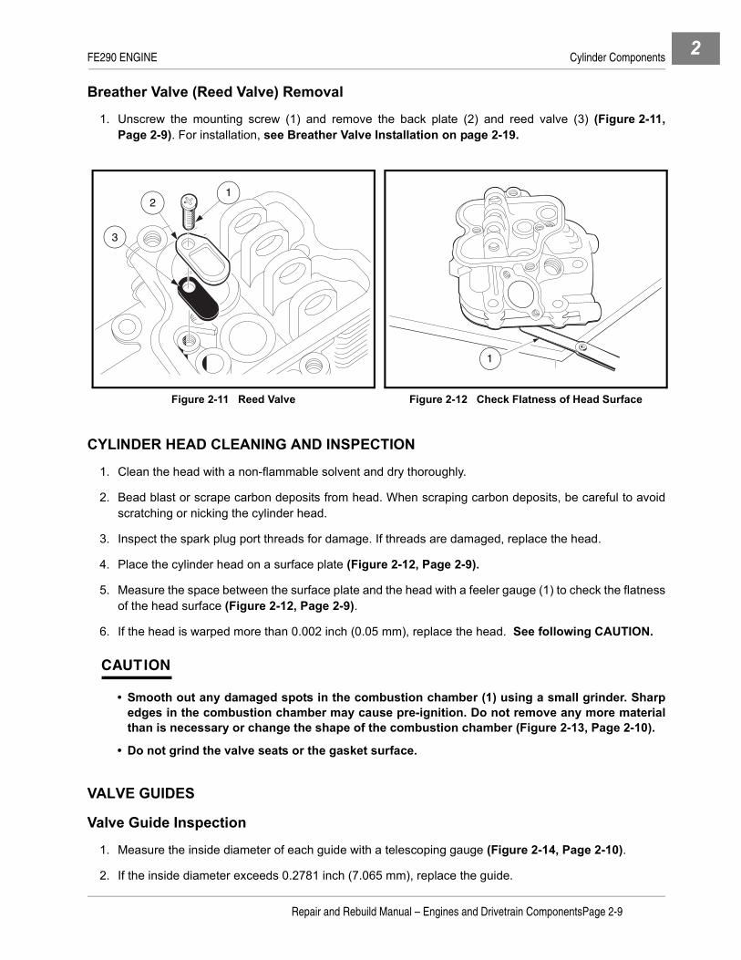
1. Unscrew the mounting screw (1) and remove the back plate (2) and reed valve (3) (Figure 2-11,Page 2-9). For installation, see Breather Valve Installation on page 2-19.
CYLINDER HEAD CLEANING AND INSPECTION
1. Clean the head with a non-flammable solvent and dry thoroughly.
2. Bead blast or scrape carbon deposits from head. When scraping carbon deposits, be careful to avoidscratching or nicking the cylinder head.
3. Inspect the spark plug port threads for damage. If threads are damaged, replace the head.
4. Place the cylinder head on a surface plate (Figure 2-12, Page 2-9).
5. Measure the space between the surface plate and the head with a feeler gauge (1) to check the flatnessof the head surface (Figure 2-12, Page 2-9).
6. If the head is warped more than 0.002 inch (0.05 mm), replace the head. See following CAUTION.
CAUTION
• Smooth out any damaged spots in the combustion chamber (1) using a small grinder. Sharpedges in the combustion chamber may cause pre-ignition. Do not remove any more materialthan is necessary or change the shape of the combustion chamber (Figure 2-13, Page 2-10).
• Do not grind the valve seats or the gasket surface.
VALVE GUIDES
Valve Guide Inspection
1. Measure the inside diameter of each guide with a telescoping gauge (Figure 2-14, Page 2-10).
2. If the inside diameter exceeds 0.2781 inch (7.065 mm), replace the guide.
Figure 2-11 Reed Valve Figure 2-12 Check Flatness of Head Surface
1
3
2
1
Repair and Rebuild Manual – Engines and Drivetrain ComponentsPage 2-9

FE290 ENGINE Cylinder Components2
Valve Guide Inspection, Continued:
Valve Guide Replacement
1. With the combustion chamber side of the head facing up, drive the guide out of the head with a valveguide arbor (1) (CCI P/N 101641202) (Figure 2-15, Page 2-10).
2. Install the snap ring (2) on the new valve guide (Figure 2-16, Page 2-10).
3. Coat the guide with a light film of clean engine oil.
4. With the rocker arm side of the head facing up, drive the new valve guide into the head with the valveguide arbor (3) until the snap ring (2) just seats on the head (Figure 2-16, Page 2-10).
5. Ream the guide with a stanisol or kerosene lubricant and a valve guide reamer (CCI P/N 101641201).The valve guide inside diameter should be 0.2756 - 0.2762 inch (7.000 - 7.015 mm) (Figure 2-17,Page 2-11).
Figure 2-13 Combustion Chamber Figure 2-14 Measure I.D. of Valve Guides
Figure 2-15 Valve Guide Removal Figure 2-16 Valve Guide Installation
1 A
A
B
A21
Measure each positionin 2 places 90 apart.
1
3
2
Page 2-10Repair and Rebuild Manual – Engines and Drivetrain Components

FE290 ENGINE Cylinder Components 2
VALVE SEATSSee General Warning on page 1-1.Valve Seat Inspection
1. Inspect the valve seats for damage. If the seats are warped or distorted beyond reconditioning, replacethe cylinder head.
2. Use prussian blue metal die to coat the valve seat.
3. Push the valve into the guide.
4. Rotate the valve against the seat with a lapping tool (1) (Figure 2-18, Page 2-11).
5. Pull the valve out and check the mark on the valve head. It must be 0.0197 - 0.0433 inch (.50 - 1.10 mm)in width and even all the way around the seat and valve (Figure 2-19, Page 2-11).
NOTE: The valve stem and guide must be in good condition or step 5 will not be valid.
6. If the valve seating surface is not correct or if it is , worn or pitted, the seat can be resurfaced. See ValveSeat Repair on page 2-12. Lap the valves to the seats after resurfacing.
Figure 2-17 Ream Valve Guide Figure 2-18 Rotate Valve against Valve Seat
Figure 2-19 Check Mark on Valve Head
VALVE SEAT
1
0.0197 inch/0.0433 inch(.50/1.10 mm)
Repair and Rebuild Manual – Engines and Drivetrain ComponentsPage 2-11

FE290 ENGINE Cylinder Components2
Valve Seat Repair
CAUTION
• If you are unfamiliar with the following procedures, Club Car suggests that the cylinder headbe taken to a professional engine machine shop for reconditioning.
1. Clean the cylinder head thoroughly. See Cylinder Head Cleaning and Inspection on page 2-9.
2. Recondition the valve seats with valve seat cutters (1) (45° x 32 mm exhaust seat CCI P/N 1016553, 45°x 35 mm intake seat CCI P/N 1016554) (Figure 2-21, Page 2-13).
2.1. Use prussian blue and check the seats for good contact all the way around. See Valve Seats onpage 2-11.
2.2. Measure the seat width of the 45° angle portion of the seat at several places around the seat(Figure 2-20, Page 2-13).
2.3. If the seat width is more than 0.079 inch (2.0 mm), the seating surface should be resurfaced.
2.4. Resurface the valve seats with 45° cutter (1) (32 mm exhaust seat), and (35 mm intake seat) cut-ters, removing only enough material to produce a smooth and concentric seat (Figure 2-21,Page 2-13). See following CAUTION.
CAUTION
• Use care not to dull the cutter. Do not turn the cutter counterclockwise or allow it to hit a metalobject.
2.5. Use a 30° x 35 mm seat cutter (1) (CCI P/N 1016554) to narrow the seat width to the standard width(Figure 2-21, Page 2-13). See following CAUTION and NOTE.
2.6. Turn the seat cutter (1) clockwise one turn at a time while pressing down very lightly. Recheck thewidth after each cutter revolution. See following CAUTION and NOTE.
CAUTION
• The 30° x 35 mm seat cutter removes material very quickly. Check the seat outside diameterfrequently to prevent over-cutting.
NOTE: Keep the seat width as close as possible to 0.031 inch (0.8 mm).
2.7. Make a light pass with the 45° cutter (1) (32 mm exhaust valve seat cutter), and (35 mm intake valveseat cutter) to remove any possible burrs at the edge of the seat.
3. After applying a coat of prussian blue to the valve face, insert the valve, and snap it closed against theseat several times. The valve surface should show good contact all the way around. Be sure the valveseat is centered on the valve face. The position of the valve in the seat is evident after lapping the valve.
4. If the seat does not make proper contact, lap the valve into the seat with a vacuum cup tool.
4.1. Coat the surface of the valve sparingly with a fine lapping compound.
Page 2-12Repair and Rebuild Manual – Engines and Drivetrain Components

FE290 ENGINE Cylinder Components 2
4.2. Use the vacuum cup lapping tool (1) to grip the top of the valve. Rotate the valve in a circular motionto lap the valve to the seat (Figure 2-22, Page 2-13).
4.3. Lift the valve slightly from the seat every 8 to 10 strokes, continuing the lapping operation until a uni-form ring appears around the entire surface of the valve face.
5. When lapping is completed, wash all parts in solvent to remove lapping compound. Dry the parts thor-oughly.
6. Note the position of the lapping mark on the valve face. The lapping mark should appear on or near thecenter of the face.
7. When the engine is assembled, be sure to adjust the valve clearance. See Valve Clearance Check andAdjustment on page 2-18.
VALVESVisual Inspection
1. Inspect the valve head seating area (1) for erosion, nicks and warping, etc. (Figure 2-23, Page 2-13).
NOTE: The valve seating surface angle for the FE290 engine is 45° (Figure 2-24, Page 2-14).
2. If the valve head seating area is worn, replace the valve.3. If the valve head seating area is eroded or nicked, it may be possible to repair the valve on a valve refac-
ing machine. Follow the refacing machine manufacturer’s instructions.
Figure 2-20 Measure Seat Width Figure 2-21 Resurface Valve Seat
Figure 2-22 Lap Valve to Seat Figure 2-23 Valve Head Seating Area
0
0
10
1020
20
30
3040
40
50
5060
60
70
70 80
80
90
90
1
1
1
Repair and Rebuild Manual – Engines and Drivetrain ComponentsPage 2-13

FE290 ENGINE Cylinder Components2
4. Inspect the stem for obvious wear, discoloration, and stem end damage.
5. If the stem is obviously worn or discolored, replace the valve.
Valve Head Thickness1. Measure the thickness of the valve head (Figure 2-24, Page 2-14).
2. If the valve head thickness (A) is less than 0.024 inch (0.610 mm), replace the valve.
Valve Stem Bend1. Support the valve in V-blocks at each end of the stem (Figure 2-25, Page 2-14).
2. Position a dial gauge perpendicular to the stem.
3. Turn the valve and read the variation on the dial gauge.
4. If stem bend is greater than the service limit of 0.0012 inch (0.0305 mm), replace the valve.
Figure 2-24 Valve Seating Surface Area
Figure 2-25 Measure Valve Stem Bend Figure 2-26 Measure Valve Stem Diameter
A
45
A 2
A
BCD D
CB
A11
11
11
11
A1
Measure each positionin 2 places 90 apart.
Page 2-14Repair and Rebuild Manual – Engines and Drivetrain Components

FE290 ENGINE Cylinder Components 2
Valve Stem Diameter
1. Using a micrometer, measure the diameter of the stem at several points along its length (Figure 2-26,Page 2-14).
2. If the outside diameter is less than the service limit of 0.2728 inch (6.930 mm) intake, 0.2722 inch (6.915mm) exhaust, replace the valve.
Valve Spring Inspection
1. Inspect the valve springs (1) for pitting, cracks, corrosion, and burrs. Replace the springs if necessary(Figure 2-27, Page 2-15).
2. Measure the free length of the spring. If the measurement is less than the service limit of 1.29 inch (32.77mm), replace the spring.
Valve Installation
1. Valve installation is the reverse of removal. See Valve Removal on page 2-8. See following NOTE.
NOTE: Valve spring coils are closer together (have a narrower pitch) at one end of the spring than at theother. Install springs with the narrow pitch ends down on the spring seats (Figure 2-27,Page 2-15).
ROCKER ARM AND ROCKER SHAFT INSPECTION
1. Use a dial bore or telescoping gauge to measure the inside diameter of each rocker arm bearing at sev-eral points along its length (Figure 2-28, Page 2-16).
2. If the inside diameter is more than the service limit of 0.4754 inch (12.075 mm), replace the rocker arm.
3. Use a micrometer to measure the outside diameter of the rocker shaft at several points along its length(Figure 2-29, Page 2-16).
4. If the outside diameter is less than the service limit of 0.4704 inch (11.949 mm), replace the shaft.
Figure 2-27 Measure Free Length of Spring
0
010
1020
2030
3040
405050
60
60
70
7080
80
90
90
00.5
1.0
1Coils closer together on one end
Repair and Rebuild Manual – Engines and Drivetrain ComponentsPage 2-15

FE290 ENGINE Cylinder Components2
PUSH ROD INSPECTION1. Support the rod in V-blocks at each end of rod. Position a dial gauge perpendicular to the rod
(Figure 2-30, Page 2-16).2. Turn the rod slowly and read the variation on the gauge.
3. If the push rod is bent more than 0.012 inch (0.3 mm), replace the push rod.
CYLINDER HEAD INSTALLATIONSee General Warning on page 1-1.
1. Installation is the reverse of removal. See Cylinder Head Removal on page 2-7.2. Position each push rod (5) between the rocker arm (3) and the tappet (6), then insert the rocker shaft (2)
through the head posts and rocker arms (3) and washer (4) (Figure 2-31, Page 2-17 and Figure 2-32,Page 2-17).
Figure 2-28 Measure I.D. of Rocker Arm Bearing Figure 2-29 Measure O.D. of Rocker Shaft
Figure 2-30 Measure Push Rod Bend
Measure each positionin 2 places 90 apart.
A2A1
A2
A
B
C
D D
C
B
A11
11
11
11
A1
Measure each positionin 2 places 90 apart.
Page 2-16Repair and Rebuild Manual – Engines and Drivetrain Components

FE290 ENGINE Cylinder Components 2
3. Slide the washer (4) against the exhaust rocker and fit the E-ring (1) into the groove in the rocker shaft(2) (Figure 2-31, Page 2-17).
4. Install cylinder head assembly to engine.
5. Tighten the bolts down evenly by hand.
6. Use a torque wrench to tighten the six bolts in the sequence shown (Figure 2-33, Page 2-17).
7. Increase the torque in four increments of 50 in-lb (6 N·m) and then tighten to final torque of 220 in-lb (25N·m). See following CAUTION.
CAUTION
• Do not turn any one bolt down completely before tightening the others. Doing so may causethe cylinder head to warp.
8. Adjust valve clearances.
Figure 2-31 Rocker Arm Assembly Figure 2-32 Cylinder Head Installation
Figure 2-33 Bolt Torque Sequence
1 4
25
3
2
6
1
6
3
5
4
2
Repair and Rebuild Manual – Engines and Drivetrain ComponentsPage 2-17
FE290 ENGINE Cylinder Components2
VALVE CLEARANCE CHECK AND ADJUSTMENT
NOTE: Check and adjust clearance when the engine is cold.
1. Turn the crankshaft until the piston is at the top of the compression stroke.
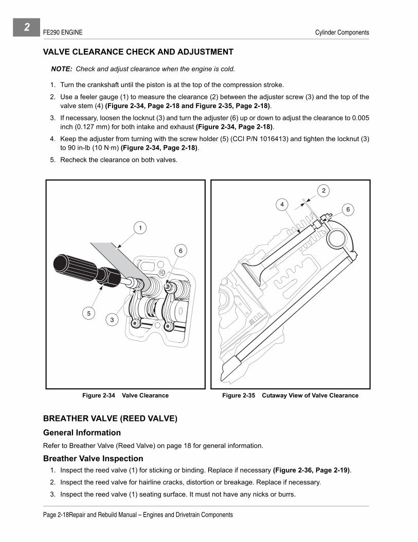
2. Use a feeler gauge (1) to measure the clearance (2) between the adjuster screw (3) and the top of thevalve stem (4) (Figure 2-34, Page 2-18 and Figure 2-35, Page 2-18).
3. If necessary, loosen the locknut (3) and turn the adjuster (6) up or down to adjust the clearance to 0.005inch (0.127 mm) for both intake and exhaust (Figure 2-34, Page 2-18).
4. Keep the adjuster from turning with the screw holder (5) (CCI P/N 1016413) and tighten the locknut (3)to 90 in-lb (10 N·m) (Figure 2-34, Page 2-18).
5. Recheck the clearance on both valves.
BREATHER VALVE (REED VALVE)General InformationRefer to Breather Valve (Reed Valve) on page 18 for general information.
Breather Valve Inspection1. Inspect the reed valve (1) for sticking or binding. Replace if necessary (Figure 2-36, Page 2-19).
2. Inspect the reed valve for hairline cracks, distortion or breakage. Replace if necessary.
3. Inspect the reed valve (1) seating surface. It must not have any nicks or burrs.
Figure 2-34 Valve Clearance Figure 2-35 Cutaway View of Valve Clearance
53
1
6
2
64
Page 2-18Repair and Rebuild Manual – Engines and Drivetrain Components

FE290 ENGINE Cylinder Components 2
Breather Valve Installation1. Installation is the reverse of removal. See Breather Valve (Reed Valve) Removal on page 2-9.
NOTE: Place the reed valve on the seat so there is a slight gap (2) of 0.008 inch (0.203 mm) maximumbetween the valve and the seat (Figure 2-36, Page 2-19).
INSTALLATION OF REMAINING ENGINE COMPONENTSSee General Warning on page 1-1.
1. Install rocker cover.
2. Install lower, upper, and head shrouds (1) along with two-ended bolt (2) (Figure 2-37, Page 2-20).
NOTE: The shorter threaded end of the two-ended bolt (2) goes through washer and upper shroud.
To prevent leaks, apply a light coat of clean engine oil to the O-ring seal (7) before installation. Careshould be taken during installation to avoid cutting or nicking the O-ring seal (Figure 2-37,Page 2-20).
3. Install oil filler tube (6) and O-Ring (7) into the large hole in the crankcase cover. Install the upper end ofthe oil filler tube (6) onto the two-ended bolt (2). Install flange nut (8) and tighten to 50 in-lb (5.7 N·m).
4. Connect the ground wire (3) to the two-ended bolt and install and tighten the locknut (4) to 50 in-lb (5.7N·m). Insert the dip stick (5) (Figure 2-37, Page 2-20).
5. Install muffler (Figure 2-2, Page 2-6).
NOTE: Any time the muffler is removed from the vehicle, install a new muffler clamp (CCI P/N 1017689)and muffler gasket (CCI P/N 1015330).
5.1. Loosely attach muffler (1) to muffler mounting bracket (2) with clamp (6).5.2. Place a new gasket (12) on the exhaust manifold mounting flange.5.3. Attach muffler manifold with lock washers (11) and hex nuts (10) and tighten finger-tight.5.4. Loosely attach muffler bracket (1) and governor cable bracket (13) to engine block using hex-head
cap screw (7), lock washer (8), and flat washer (9).5.5. Tighten manifold hex nuts (10) to 11 ft-lb (14.9 N·m).5.6. Tighten hex-head cap screw (7) to 14 ft-lb (18.9 N·m).5.7. Tighten muffler clamp (6) to 40 in-lb (4.5 N·m).
6. Install carburetor (11), throttle spring (12) and throttle spring bracket (13). Tighten to 50 in-lb (5.6 N·m)(Figure 2-38, Page 2-20).
Figure 2-36 Reed Valve
PLATEMOUNTING
SCREW2
1
Repair and Rebuild Manual – Engines and Drivetrain ComponentsPage 2-19

FE290 ENGINE Crankcase Components2
7. Install the spark plug and thread it in until finger tight, then tighten the plug to 20 ft-lb (27 N·m). See fol-lowing NOTE.
NOTE: Before installing the plug, check the condition of the threads in the cylinder head. Soften depositsin cylinder head threads with penetrating oil and clean the threads with a tap if necessary.
8. Earlier Style Governor Cable End:8.1. Install governor cable clevis pin (9) through cable clevis and throttle valve lever and install a new
cotter pin (10) (Figure 2-38, Page 2-20).9. Current Style Governor Cable End:
9.1. Install ’Z’ shaped cable end into carburetor throttle valve lever (Figure 2-38, Page 2-20).10. Install the governor guard (8), flat washer (15), and nylon locknut (14). Tighten to 30 in-lb (3.4 N·m)
(Figure 2-38, Page 2-20).11. Apply a light film of clean engine oil onto the seal of the new oil filter and install the filter. Tighten the filter
2/3 turn after gasket contact. Fill crankcase with the correct level of oil.
CRANKCASE COMPONENTS
See General Warning on page 1-1.If the crankcase needs to be disassembled, the following procedures will apply.
1. Remove items associated with the cylinder assembly. See Cylinder Shroud Removal on page 2-4.2. Remove crankcase oil drain plug and filler tube. Tip the engine slightly to allow all of the oil to drain from
the crankcase. Dispose of engine oil properly.
CRANKCASE COVER REMOVAL1. Remove yellow jumper wire (11) from cord connector (12) (Figure 2-39, Page 2-21).2. Remove nuts and clamps at two-ended bolts (1 and 2) (Figure 2-40, Page 2-21).3. Remove eight bolts (3) and remove the crankcase cover (4) (Figure 2-40, Page 2-21). See following
NOTE.
NOTE: If the crankcase cover sticks, tap lightly with a plastic mallet on alternate sides near the dowel pins(5).
Figure 2-37 Oil Filler Tube and Ground Wire Figure 2-38 Governor Cable Connection
1
7 6 5
2 34
8
10
9
14158
13
12
11
Page 2-20Repair and Rebuild Manual – Engines and Drivetrain Components

FE290 ENGINE Crankcase Components 2
4. Remove the crankcase cover gasket completely.
Oil Level Sensor Removal1. Disconnect the oil level sensor wire (2) from the cord connector (1) (Figure 2-41, Page 2-21).
2. Remove the screw (3) from the wire clamp (4).
3. Remove the two mounting screws (8) from the inside of the crankcase cover and remove the oil levelsensor and bracket.
4. If necessary, remove the three screws (7) that hold the sensor to the bracket (5).
Oil Level Sensor Installation1. If the oil level sensor was removed from the bracket, install sensor (6) into bracket (5) and secure with
three screws (7) (Figure 2-41, Page 2-21). Tighten to 17 in-lb (1.9 N·m).
2. Position sending unit and bracket on inside of crankcase and install two mounting screws.
3. Connect sensor wire (2) to cord connector (1).
4. Install screw (3) through wire clamp and into crankcase cover. Tighten to 30 in-lb (3.4 N·m).
Figure 2-39 Oil Level Sensor Wire Figure 2-40 Crankcase Cover
Figure 2-41 Oil Level Sensor Figure 2-42 Timing Mark Alignment
STARTER/GENERATOR
12
11
3
4
1
2
55
TYPICAL 2 PLACES
TYPICAL 3 PLACES
1
4
32
9
8
5
6
71
Repair and Rebuild Manual – Engines and Drivetrain ComponentsPage 2-21
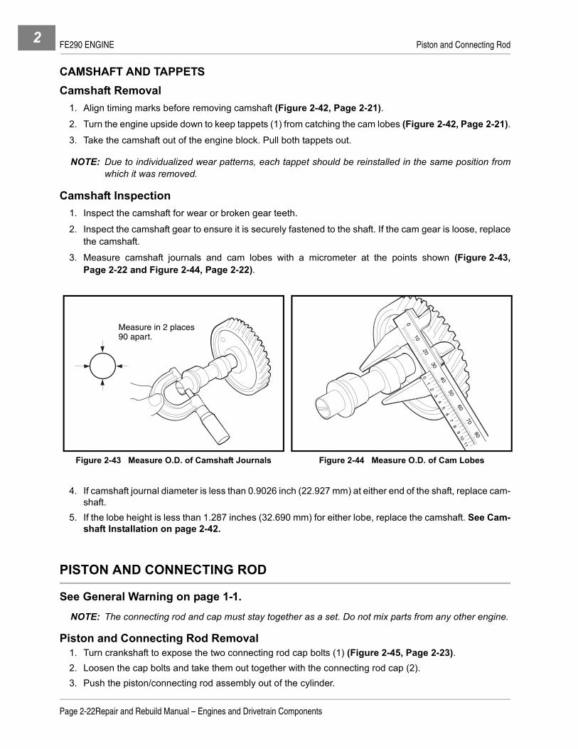
FE290 ENGINE Piston and Connecting Rod2
CAMSHAFT AND TAPPETSCamshaft Removal
1. Align timing marks before removing camshaft (Figure 2-42, Page 2-21).2. Turn the engine upside down to keep tappets (1) from catching the cam lobes (Figure 2-42, Page 2-21).3. Take the camshaft out of the engine block. Pull both tappets out.
NOTE: Due to individualized wear patterns, each tappet should be reinstalled in the same position fromwhich it was removed.
Camshaft Inspection1. Inspect the camshaft for wear or broken gear teeth.
2. Inspect the camshaft gear to ensure it is securely fastened to the shaft. If the cam gear is loose, replacethe camshaft.
3. Measure camshaft journals and cam lobes with a micrometer at the points shown (Figure 2-43,Page 2-22 and Figure 2-44, Page 2-22).
4. If camshaft journal diameter is less than 0.9026 inch (22.927 mm) at either end of the shaft, replace cam-shaft.
5. If the lobe height is less than 1.287 inches (32.690 mm) for either lobe, replace the camshaft. See Cam-shaft Installation on page 2-42.
PISTON AND CONNECTING ROD
See General Warning on page 1-1.NOTE: The connecting rod and cap must stay together as a set. Do not mix parts from any other engine.
Piston and Connecting Rod Removal1. Turn crankshaft to expose the two connecting rod cap bolts (1) (Figure 2-45, Page 2-23).2. Loosen the cap bolts and take them out together with the connecting rod cap (2).3. Push the piston/connecting rod assembly out of the cylinder.
Figure 2-43 Measure O.D. of Camshaft Journals Figure 2-44 Measure O.D. of Cam Lobes
Measure in 2 places90 apart.
010
2030
01
23
45
67
89
1011
4050
6070
80
Page 2-22Repair and Rebuild Manual – Engines and Drivetrain Components

FE290 ENGINE Piston and Connecting Rod 2
Piston and Connecting Rod Separation1. Remove the two retaining rings holding the piston pin in place.
2. Remove the piston pin.
Piston Inspection and Repair1. Remove all deposits from the piston.
2. Clean the carbon from the piston ring grooves. See following CAUTION.
CAUTION
• Never clean the piston head with the engine assembled. Carbon particles will fall between thepiston and cylinder wall and may cause severe cylinder wear.
3. Be sure the oil return passages in the ring grooves are open.
4. Visually inspect the piston rings and ring grooves for uneven wear or damage. Replace the piston and/or piston rings if uneven wear or damage is present or if they exceed the wear limits.
5. Use a new piston ring and a feeler gauge and measure the clearance between the grooves and ring atseveral points around the grooves (Figure 2-46, Page 2-23).
6. If the top groove has a clearance greater than 0.0063 inch (0.16 mm), replace the piston.
7. If the second groove has a clearance greater than 0.0055 inch (0.14 mm), replace the piston.
8. The oil ring is made of three pieces: upper and lower rails and expander. It is difficult to measure the ringgroove clearance and thickness. Inspect visually for wear or damage.
Piston Ring Inspection1. Insert the ring squarely into the cylinder bore to a point approximately 1 inch (25 mm) down from the top
the cylinder. See following NOTE.
NOTE: Use the top of the piston to push the ring into the bore to be sure it is square.
2. Use a feeler gauge to measure the ring end-gap (Figure 2-47, Page 2-24).
3. If the end-gap of any ring is greater than 0.0472 inch (1.199 mm), replace the entire set of rings.
Figure 2-45 Connecting Rod Cap Bolts Figure 2-46 Measure Piston Ring and Groove Clearance
1
2
Repair and Rebuild Manual – Engines and Drivetrain ComponentsPage 2-23

FE290 ENGINE Piston and Connecting Rod2
4. Use a micrometer to measure the thickness of both piston rings at several points around the rings(Figure 2-48, Page 2-24).
5. If either ring thickness is less than 0.0566 inch (1.438 mm), replace the entire set of rings.
NOTE: It is difficult to measure exactly the oil ring thickness. Replace the oil ring whenever the compres-sion rings (top and second) are replaced.
If a chrome ring is included as part of the ring set, always assemble it into the top piston groove.
Piston Pin Inspection1. Use a micrometer to measure the outside diameter of the piston pin at several points along its length
(Figure 2-49, Page 2-24).
2. If the pin diameter is smaller than 0.747 inch (18.974 mm), replace the piston pin.
3. Use an inside micrometer or telescoping gauge to measure the inside diameter of the piston pin hole inthe piston at several points (Figure 2-50, Page 2-24).
4. If the inside diameter exceeds 0.7439 inch (18.895 mm), replace the piston.
Figure 2-47 Measure Ring End-Gap Figure 2-48 Measure Piston Ring Thickness
Figure 2-49 Measure O.D. of Piston Pin Figure 2-50 Measure I.D. of Piston Pin Hole
A
B
C
D
E
A2
A1
Measure each dimension in 2 places, 90 apart.
A
B
C
D D
C
B
A11
11
11
11Measure eachdimension in 2
places, 90 apart.
A1 A2
Page 2-24Repair and Rebuild Manual – Engines and Drivetrain Components

FE290 ENGINE Cylinder Block 2
Connecting Rod Inspection1. Clean and inspect the bearing surfaces of the connecting rod and cap. Replace parts if scored.2. Use an inside micrometer or a telescoping gauge to measure the inside diameter of the connecting rod
small bore at several points along its length (Figure 2-51, Page 2-25).3. If the inside diameter exceeds 0.7500 inch (19.050 mm), replace the connecting rod.4. Remount the connecting rod cap to the connecting rod at the large bore end, aligning the pilot groove on
the rod. Attach the connecting rod bolts and tighten them to 16.5 ft-lb (23 N·m).5. Use a telescoping gauge or an inside micrometer to measure the inside diameter of the large bore at sev-
eral points along its length (Figure 2-52, Page 2-25).
6. If the inside diameter exceeds 1.4003 inches (35.568 mm), replace the connecting rod. See followingNOTE.
NOTE: If the connecting rod is bent or twisted, it must be replaced.
CAUTION
• The connecting rod and cap must stay together as a set. Do not mix with parts from any otherengine.
Piston and Connnecting Rod InstallationSee Piston and Connecting Rod Installation on page 2-39.
CYLINDER BLOCK
See General Warning on page 1-1.When the engine is disassembled, inspect the cylinder block for cracks, stripped bolt holes, broken fins, orcylinder wall scoring. Repair or replace as necessary.
1. Use an inside micrometer or telescoping gauge, together with a micrometer, to measure the cylinderbore.
2. Make the first measurement parallel with the crankshaft and the second at right angles to the crankshaftat three different locations in the bore. The first measurement location is 0.4 inch (10 mm) from the topof the cylinder. The second location is in the center or 2.4 inches (60 mm) from the top, and the third loca-tion is 0.3 (8 mm) from the bottom of the cylinder or bottom of ring travel. See locations 1, 2, and 3(Figure 2-53, Page 2-26).
Figure 2-51 Measure I.D. of Small Bore Figure 2-52 Measure I.D. of Large Bore
Measure dimensionsin 2 places,90 apart.
A A21
A A21Measure each side
of oil groovein 2 places,90 apart.
Repair and Rebuild Manual – Engines and Drivetrain ComponentsPage 2-25

FE290 ENGINE Cylinder Block2
• The standard bore diameter is 3.0700 - 3.0708 inches (77.980 - 78.000 mm).
• The maximum cylinder bore diameter wear limit is 3.0735 inches (78.067 mm).
• The maximum acceptable out of round cylinder bore is 0.0022 inch (0.056 mm).
3. If the cylinder bore is not within these measurements, the cylinder bore will need to be resized.
To Resize Bore to Next OversizeAlways resize the bore to exactly 0.010 inch (0.25 mm) or to exactly 0.020 inch (0.50 mm) over standard size.
1. When the bore is resized to 0.010 inch over standard size, the new bore dimension is 3.0791 - 3.0799inches (78.210 - 78.230 mm). When the bore is resized to 0.020 inch over standard size, the new boredimension is 3.0890 - 3.0898 inches (78.460 - 78.480 mm). See Specifications for Resizing CylinderBore on page 2-46.
NOTE: Allow for shrinkage (from the final size) of 0.0003 - 0.0004 inch (0.0076 - 0.0102 mm), which willoccur when the cylinder cools down.
2. Hone the cylinder that is to be 0.010 inch over standard size so that the final bore size diameter is 3.0799- 3.0807 inches (78.230 - 78.250 mm). The final honed bore diameter for a 0.020 inch over standard sizebore is 3.0898 - 3.0906 inches (78.480 - 78.500 mm). See Specifications for Resizing Cylinder Boreon page 2-46. See following NOTE.
NOTE: It is important that the cylinder wall finish should have a 40° to 60° cross-hatch pattern(Figure 2-54, Page 2-26).
Do not use solvents or gasoline to clean cylinder after honing. Solvents and gasoline allow thegrindings to remain in the honed surface and will not provide a surface suited for ring seating.
3. After honing, clean the cylinder wall thoroughly using soap, warm water and clean rags.
4. Dry the cylinder and coat with engine oil. See following CAUTION.
CAUTION
• The cylinder must be thoroughly cleaned after honing to eliminate all grit.
Figure 2-53 Measure Cylinder Bore Figure 2-54 Hone Cylinder
1
2
3
Measure each levelin bore at 2 places,90 apart.
3 1
3 1
HONING TOOL
Page 2-26Repair and Rebuild Manual – Engines and Drivetrain Components

FE290 ENGINE Ignition Coil and Flywheel 2
IGNITION COIL AND FLYWHEEL
See General Warning on page 1-1.Ignition Coil and Flywheel Removal
1. Loosen three screws and remove the remaining four screws attaching the flywheel housing, then removethe housing (Figure 2-55, Page 2-27).
2. Disconnect the ignition coil (1) from its primary lead wire at the connector (2). Remove the two bolts (3)and remove the ignition coil (Figure 2-56, Page 2-27).
3. Hold the flywheel (4), not the fan (7), with a strap wrench (5) and use a 22 mm socket to remove the fly-wheel nut (and flat washer) by turning it counterclockwise (Figure 2-57, Page 2-28). See followingCAUTION.
CAUTION
• The flywheel nut has right-hand threads. Turn it clockwise to tighten, or counterclockwise toloosen.
• Do not damage the fan blades with the strap wrench. Do not place screwdriver or pry bar inthe fan blades.
4. Remove the flywheel with a puller (CCI P/N 1016627).
5. Remove the flywheel key from its groove.
Flywheel InstallationSee Engine Assembly on page 2-43.
Ignition Coil InstallationIt is recommended that the ignition coil (CCI P/N 101909201) be replaced with engine teardown.
1. Installation is the reverse of removal.
Figure 2-55 Flywheel Housing Figure 2-56 Ignition Coil
Loosen.
Remove.
Remove.
2
1
3
Repair and Rebuild Manual – Engines and Drivetrain ComponentsPage 2-27

FE290 ENGINE Ignition Coil and Flywheel2
2. Lightly tighten the two bolts (3), then use a bronze feeler gauge to adjust the ignition coil air gap to 0.012inch (0.304 mm) (Figure 2-58, Page 2-28).
3. Tighten the two ignition coil bolts to 30 in-lb (3.4 N·m).
Figure 2-57 Flywheel Nut Figure 2-58 Adjust Ignition Coil Air Gap
Figure 2-59 Oil Pump
5
7
4 MF3
481
0.012 inch(0.304 mm)
3
TYPICAL 6 PLACES
1
1
3
5
2
6
4
2
2
34
5
BOLT TIGHTENING SEQUENCE
REF.
Page 2-28Repair and Rebuild Manual – Engines and Drivetrain Components

FE290 ENGINE Oil Pump 2
OIL PUMP
See General Warning on page 1-1.Oil Pump Cover Removal
1. Remove the six screws (1) and take off the oil pump cover (2) (Figure 2-59, Page 2-28).2. Peel off the oil pump cover gasket (3).3. Remove the pump gear cover plate (4) (Figure 2-59, Page 2-28).
Oil Pump Inspection1. Check the clearance between the inner and outer rotors (5) with a feeler gauge (6). Measure the clear-
ance between the high point of the inner rotor and the high point of the outer rotor (Figure 2-60,Page 2-29).
2. Replace both rotors as a set if the measurement exceeds 0.012 inch (0.3 mm).3. Remove inner and outer rotors (5).4. Inspect the inner and outer oil pump rotors. If the rotors are worn or damaged, replace them.
4.1. Measure the pump shaft bearing surface. Replace both rotors as a set if the measurement is lessthan 0.4971 inch (12.627 mm) (Figure 2-61, Page 2-29).
4.2. Use a micrometer to measure the diameter of the outer rotor at several points (Figure 2-62,Page 2-29).
4.3. If the rotor diameter is less than 1.5931 inches (40.467 mm), replace both rotors.4.4. Use a micrometer to measure the thickness of the outer rotor (Figure 2-63, Page 2-29).4.5. If the rotor thickness is less than 0.3905 inch (9.920 mm), replace both rotors.
Figure 2-60 Check Clearance Between Rotors Figure 2-61 Measure Pump Shaft Bearing Surface
Figure 2-62 Measure O.D. of Outer Rotor Figure 2-63 Measure Thickness of Outer Rotor
6
5
5
A
B
Measure twoplaces 90 apart.
5
A B
Measure twoplaces 90 apart.
ABCDE
5
Repair and Rebuild Manual – Engines and Drivetrain ComponentsPage 2-29

FE290 ENGINE Oil Pump2
OIL PRESSURE RELIEF VALVE
Oil Pressure Relief Valve Removal
1. Remove the oil pump cover. See Oil Pump Cover Removal on page 2-29.
2. Remove the valve seat (1), ball (2) and spring (3) (Figure 2-64, Page 2-30).
Oil Pressure Relief Valve Inspection
1. Note the condition of the ball (2) and the valve seat (1). They must not have any nicks or burrs(Figure 2-64, Page 2-30).
2. Inspect the relief valve spring (3) for pitting, cracks, rusting and burrs. Replace it if necessary.
3. Measure free length of the spring (3) with a vernier caliper (Figure 2-65, Page 2-30). If the free lengthof the relief valve spring is less than 0.748 inch (19.00 mm), replace the spring.
Oil Pressure Relief Valve Installation
1. Installation is the reverse of removal. If necessary, put the ball in position and lightly tap the ball with aplastic hammer to form a perfect seat.
Oil Pump Installation
CAUTION
• Do not allow any dust or other foreign matter into the oil pump.
1. Installation is the reverse of removal.
2. Install the inner rotor with its tang in the slot in the end of the camshaft (Figure 2-66, Page 2-31).
3. Install six bolts (1) and finger tighten. Then tighten to 7 ft-lb (9.5 N·m) in the sequence shown(Figure 2-59, Page 2-28). After tightening bolts, check torque of first bolt.
Figure 2-64 Oil Pressure Relief Valve Figure 2-65 Measure Free Length of Spring
1
32
OILPUMP
0
010
1020
2030
3040
405050
60
60
70
7080
80
90
90
3
Page 2-30Repair and Rebuild Manual – Engines and Drivetrain Components

FE290 ENGINECrankshaft and Counterbalance 2
CRANKSHAFT AND COUNTERBALANCE
See General Warning on page 1-1.
Crankshaft and Counterbalance Removal1. Remove the four nuts (1) and pull out the counterbalance guide shaft (2) and the O-Ring (3)
(Figure 2-67, Page 2-31).
2. Pull out the crankshaft and the counterbalance together as an assembly (Figure 2-68, Page 2-32).
Crankshaft and Counterbalance Disassembly1. Slide the spacer (2) and the link rod (3) off the flywheel end of the crankshaft. Remove the counterbal-
ance from the remaining link rod (Figure 2-68, Page 2-32). See Link Rod Inspection on page 2-33.
2. If the link rods need replacing, place the gear yoke (CCI P/N 1016418) under the spur gear with the smallend of the connecting rod located opposite the crankpin (Figure 2-70, Page 2-32).
3. Position the gear yoke with the side blocks positioned as close to the crankshaft as possible(Figure 2-70, Page 2-32).
4. Use a press to push on the end of the crankshaft to remove the spur gear and the helical gear off thecrankshaft (Figure 2-71, Page 2-32). See following WARNING and CAUTION.
ý WARNING
• Support the crankshaft while pressing. This will prevent the crankshaft from dropping to thefloor after the gear has been removed.
CAUTION
• Use a press when removing the spur gear and helical gear from, or installing them on, thecrankshaft.
5. Remove the woodruff key.
6. Slide the remaining link rod off the crankshaft.
Figure 2-66 Install Inner Rotor Figure 2-67 Counterbalance Guide Shaft and O-Ring
TANG
6
SLOT
5
2
3
1
Repair and Rebuild Manual – Engines and Drivetrain ComponentsPage 2-31

FE290 ENGINECrankshaft and Counterbalance2
Figure 2-68 Crankshaft and Counterbalance Figure 2-69 Inspect Link Rod
Figure 2-70 Place Assembly In Press Figure 2-71 Remove Helical and Spur Gears
2
3
1
TYPICAL 4 PLACES
HELICAL GEAR GEAR YOKE
SPUR GEAR
SIDE BLOCKS (2)
PRESSTABLE
PRESS RAM
PRESSTABLE
GEAR YOKE
SIDE BLOCKS
Page 2-32Repair and Rebuild Manual – Engines and Drivetrain Components

FE290 ENGINECrankshaft and Counterbalance 2
Link Rod Inspection
1. Clean and inspect the link rod (1) bearing surfaces. If the bearing surface of the small end is scored ordamaged, replace the link rod. If the large end bearing is scored or damaged, the bearing must bereplaced (Figure 2-69, Page 2-32).
1.1. Use a telescoping gauge and micrometer, measure both inside bearing surfaces at several points.
1.2. If the inside diameter of the small end is greater than 0.4746 inch (12.057 mm), replace the link rod(Figure 2-72, Page 2-33).
1.3. If the inside diameter of the large end is greater than 1.8554 inches (47.127 mm), replace the bear-ing (Figure 2-73, Page 2-33). See following NOTE.
NOTE: Do not remove the link rod on the PTO (power take-off) side unless link rod on the opposite endneeds replacement. The crank-gear is very tightly fitted to the crankshaft so that it can transferengine torque to the camshaft (which also functions as a power take-off shaft) (Figure 2-69,Page 2-32). Ignore crankshaft and counterbalance disassembly (Steps 2 through 6, page 2-31),if the link rod opposite of the PTO side passes inspection (Figure 2-69, Page 2-32).
Link Rod Bushing Replacement
1. Support the link rod around the entire large end, and using a 1.97 inches (50 mm) bearing driver (1), drivethe bearing (2) out of the rod (3) as shown (Figure 2-74, Page 2-34).
2. Clean the parts thoroughly in a high flash-point solvent and dry them.
3. Coat the new bearing with new engine oil.
4. Use a 1.97 inches (50 mm) bearing driver to press the new bearing into the link rod with its seam (6)toward the side of the link rod with the hollow (5) and at right angles to the rod center, to a depth of 0.039inch (0.991 mm) from the surface (Figure 2-75, Page 2-34).
Figure 2-72 Measure I.D. of Small Bore Figure 2-73 Measure I.D. of Large Bore
A A21Measure in two places
90 apart.
A A21 Measure in two places
90 apart.
Repair and Rebuild Manual – Engines and Drivetrain ComponentsPage 2-33

FE290 ENGINECrankshaft and Counterbalance2
COUNTERBALANCE WEIGHT
NOTE: The wrist pins are tightly pressed into the weight and normally require no maintenance.
Counterbalance Weight Inspection1. Clean the inside of the bore surface and inspect it for wear or damage.
2. Use a telescoping gauge and micrometer to measure the inside diameter of the bearing bore(Figure 2-76, Page 2-34).
3. If the inside diameter is greater than 1.0283 inches (26.119 mm), or the bore show signs of wear or dam-age, replace counterbalance weight.
Counterbalance Guide Shaft Inspection1. Clean the shaft surface and inspect it for wear or damage.
2. Use an outside micrometer to measure the outside diameter of the guide shaft surface (Figure 2-77,Page 2-34).
3. If the outside diameter is smaller than 1.0199 inches (25.907 mm), or the shaft shows signs of wear ordamage, replace the guide shaft.
4. Check the O-Ring seal to make sure the O-Ring is not damaged. Replace if necessary.
Figure 2-74 Remove Bearing From Link Rod Figure 2-75 Install New Bearing Into Link Rod
Figure 2-76 Measure I.D. of Counterbalance Weight Bore
Figure 2-77 Measure O.D. of Counterbalance Guide Shaft
4
1
2
3
0.039 in.(0.991 mm)5
6
A A21
Measurein two places
90 apart.
A2
A1
Measure each position in 2 places 90 apart.
A
B
C
D D
C
B
A11
11
11
11
Page 2-34Repair and Rebuild Manual – Engines and Drivetrain Components
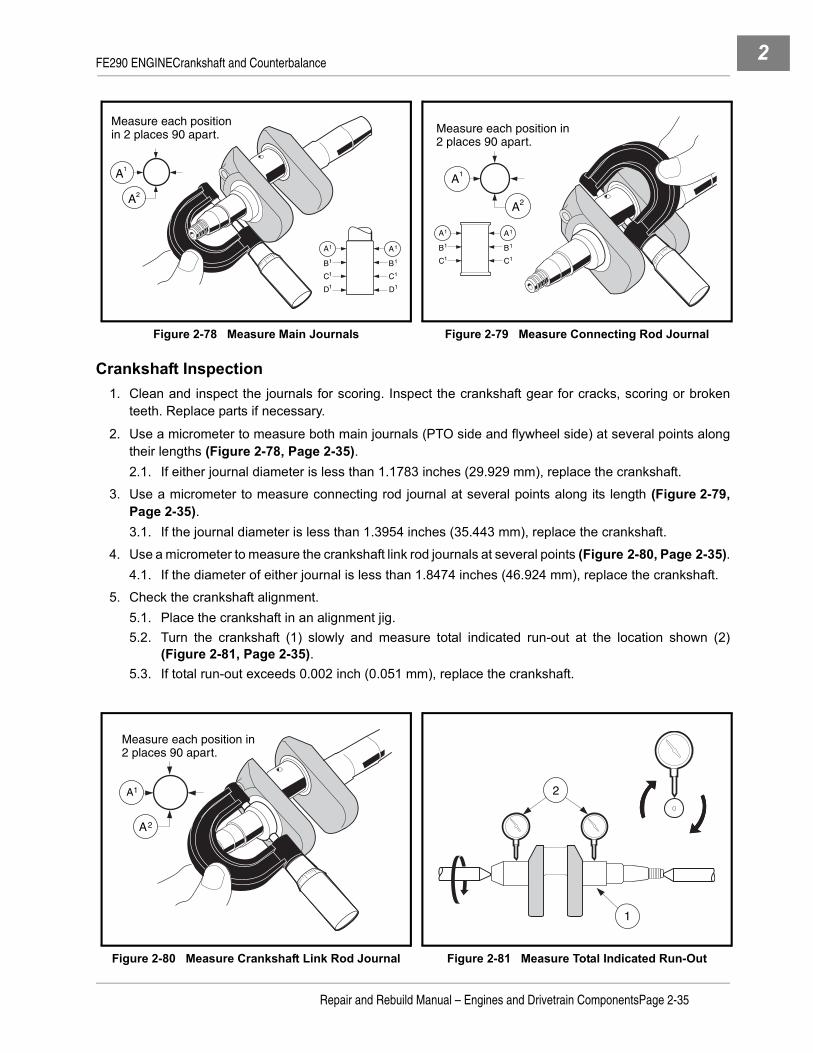
FE290 ENGINECrankshaft and Counterbalance 2
Crankshaft Inspection1. Clean and inspect the journals for scoring. Inspect the crankshaft gear for cracks, scoring or broken
teeth. Replace parts if necessary.
2. Use a micrometer to measure both main journals (PTO side and flywheel side) at several points alongtheir lengths (Figure 2-78, Page 2-35).2.1. If either journal diameter is less than 1.1783 inches (29.929 mm), replace the crankshaft.
3. Use a micrometer to measure connecting rod journal at several points along its length (Figure 2-79,Page 2-35).3.1. If the journal diameter is less than 1.3954 inches (35.443 mm), replace the crankshaft.
4. Use a micrometer to measure the crankshaft link rod journals at several points (Figure 2-80, Page 2-35).4.1. If the diameter of either journal is less than 1.8474 inches (46.924 mm), replace the crankshaft.
5. Check the crankshaft alignment.5.1. Place the crankshaft in an alignment jig.5.2. Turn the crankshaft (1) slowly and measure total indicated run-out at the location shown (2)
(Figure 2-81, Page 2-35).5.3. If total run-out exceeds 0.002 inch (0.051 mm), replace the crankshaft.
Figure 2-78 Measure Main Journals Figure 2-79 Measure Connecting Rod Journal
Figure 2-80 Measure Crankshaft Link Rod Journal Figure 2-81 Measure Total Indicated Run-Out
A2
A1
A
B
C
D D
C
B
A11
11
11
11
Measure each positionin 2 places 90 apart.
A1
A2
A
B
C C
B
A11
11
11
Measure each position in 2 places 90 apart.
A2
A1
Measure each position in 2 places 90 apart.
1
2
Repair and Rebuild Manual – Engines and Drivetrain ComponentsPage 2-35
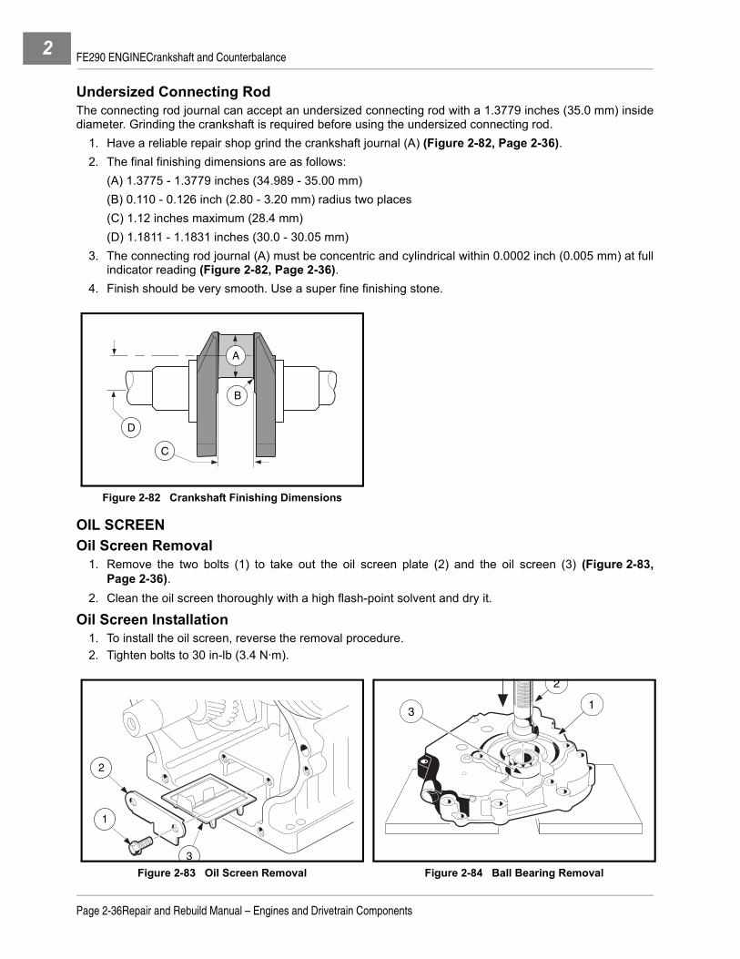
FE290 ENGINECrankshaft and Counterbalance2
Undersized Connecting RodThe connecting rod journal can accept an undersized connecting rod with a 1.3779 inches (35.0 mm) insidediameter. Grinding the crankshaft is required before using the undersized connecting rod.
1. Have a reliable repair shop grind the crankshaft journal (A) (Figure 2-82, Page 2-36).2. The final finishing dimensions are as follows:
(A) 1.3775 - 1.3779 inches (34.989 - 35.00 mm)(B) 0.110 - 0.126 inch (2.80 - 3.20 mm) radius two places(C) 1.12 inches maximum (28.4 mm)(D) 1.1811 - 1.1831 inches (30.0 - 30.05 mm)
3. The connecting rod journal (A) must be concentric and cylindrical within 0.0002 inch (0.005 mm) at fullindicator reading (Figure 2-82, Page 2-36).
4. Finish should be very smooth. Use a super fine finishing stone.
OIL SCREENOil Screen Removal
1. Remove the two bolts (1) to take out the oil screen plate (2) and the oil screen (3) (Figure 2-83,Page 2-36).
2. Clean the oil screen thoroughly with a high flash-point solvent and dry it.
Oil Screen Installation1. To install the oil screen, reverse the removal procedure.2. Tighten bolts to 30 in-lb (3.4 N·m).
Figure 2-82 Crankshaft Finishing Dimensions
Figure 2-83 Oil Screen Removal Figure 2-84 Ball Bearing Removal
C
B
A
D
3
1
2
1
2
3
Page 2-36Repair and Rebuild Manual – Engines and Drivetrain Components

FE290 ENGINECrankshaft and Counterbalance 2
BALL BEARINGBall Bearing Removal
1. Remove the oil seal in the crankcase cover. See following NOTE.
NOTE: Never reuse an oil seal. Replace the oil seal with a new one.
2. Place the crankcase cover (1) on a bench with its outside up (gasket surface against bench)(Figure 2-84, Page 2-36).
3. Use a bearing driver (2) (part of Bearing Driver Kit, CCI P/N 1016416) to drive out the ball bearing (3).
Ball Bearing Inspection1. Clean the ball bearing thoroughly in high flash-point solvent and dry it.
NOTE: Never use compressed air to dry bearing. Spinning the bearing at accelerated speeds withoutlubrication can damage both the bearings and bearing seat and result in premature bearing failure.
2. Spin the ball bearing by hand and check for (A) axial play and (B) radial play. Replace the ball bearingif it is noisy, does not spin smoothly, or if it has any play (Figure 2-85, Page 2-37).
OIL SEALSOil seals are used on both ends of the crankshaft. Any time the crankshaft is removed from the seals, theseals must be replaced with new ones.
Oil Seal RemovalUse an oil seal remover to press or drive the seal out of the casing.
Oil Seal Installation
NOTE: Never reuse an oil seal. Replace the oil seal with a new one.
1. Put a light coating of clean engine oil on the outside edge and the inner lip of the oil seal to assist instal-lation.
2. Install all oil seals with their lips facing the center of the engine.
3. Using the 1.37 inch (35 mm) seal driver, press the oil seal into the flywheel side of the crankcase until itis flush with the hole.
4. Using the 1.97 inch (50 mm) seal driver, press the oil seal into the crankcase cover until it is 0.157 inch(4 mm) below the outside surface.
Figure 2-85 Check Ball Bearing
A B
Repair and Rebuild Manual – Engines and Drivetrain ComponentsPage 2-37
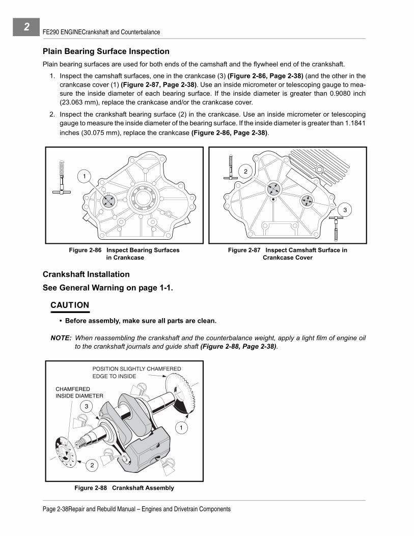
FE290 ENGINECrankshaft and Counterbalance2
Plain Bearing Surface InspectionPlain bearing surfaces are used for both ends of the camshaft and the flywheel end of the crankshaft.
1. Inspect the camshaft surfaces, one in the crankcase (3) (Figure 2-86, Page 2-38) (and the other in thecrankcase cover (1) (Figure 2-87, Page 2-38). Use an inside micrometer or telescoping gauge to mea-sure the inside diameter of each bearing surface. If the inside diameter is greater than 0.9080 inch(23.063 mm), replace the crankcase and/or the crankcase cover.
2. Inspect the crankshaft bearing surface (2) in the crankcase. Use an inside micrometer or telescopinggauge to measure the inside diameter of the bearing surface. If the inside diameter is greater than 1.1841inches (30.075 mm), replace the crankcase (Figure 2-86, Page 2-38).
Crankshaft InstallationSee General Warning on page 1-1.
CAUTION
• Before assembly, make sure all parts are clean.
NOTE: When reassembling the crankshaft and the counterbalance weight, apply a light film of engine oilto the crankshaft journals and guide shaft (Figure 2-88, Page 2-38).
Figure 2-86 Inspect Bearing Surfaces in Crankcase
Figure 2-87 Inspect Camshaft Surface in Crankcase Cover
Figure 2-88 Crankshaft Assembly
12
3
2
3
1
CHAMFEREDINSIDE DIAMETER
POSITION SLIGHTLY CHAMFEREDEDGE TO INSIDE
Page 2-38Repair and Rebuild Manual – Engines and Drivetrain Components

FE290 ENGINECrankshaft and Counterbalance 2
1. Installation is the reverse of removal. See Crankshaft and Counterbalance Removal on page 2-31.
2. Tighten the four nuts (2) for counterbalance guide shaft to 50 in-lb (5.9 N·m) (Figure 2-67, Page 2-31).
3. If the link rod was removed from the PTO side of the crankshaft, support the crankweb as shown, slidethe link rod onto the crankshaft, and install the key. Press the spur gear and helical gear onto the crank-shaft (Figure 2-89, Page 2-39 and Figure 2-90, Page 2-39). See following CAUTION and NOTE.
CAUTION
• Always use a press when removing or installing the spur gear and helical gear on thecrankshaft.
• If the spur gear was warped while being removed, install a new one.
NOTE: Make sure the chamfered inside diameters of the spur gear and helical gear are oriented down-ward on the crankshaft as shown (Figure 2-89, Page 2-39).
Make sure the link rods rotate smoothly after the gears are pressed on.
4. Slide the link rod, then the spacer, onto the flywheel end of the crankshaft.
PISTON AND CONNECTING ROD INSTALLATION1. Reassemble the piston and the connecting rod into a unit, if disassembled.
1.1. Align the arrow mark (1) on the piston head toward the words MADE IN JAPAN (2) on the connect-ing rod. Insert the piston pin through the piston holes and the connecting rod. Install the two retain-ing rings to hold the pin in place. The gap in the retaining rings should be facing towards thecrankshaft. Make sure the retaining rings are seated in their grooves. Make sure the connecting rodmoves freely (Figure 2-91, Page 2-40).
2. Apply a light film of engine oil to the connecting rod bearing surfaces and the two connecting rod bolts.
Figure 2-89 Crankshaft Installation Figure 2-90 Press On Spur Gear and Helical Gear
PRESSSLEEVE
PRESSTABLE
SPUR GEAR (CHAMFERED INSIDE DIAMETER
FACING DOWN)
LINK ROD
KEY
HELICAL GEAR(NOTE TIMING MARK)
PRESS RAM
Repair and Rebuild Manual – Engines and Drivetrain ComponentsPage 2-39

FE290 ENGINECrankshaft Axial Play Adjustment2
3. Put the piston and connecting rod into the cylinder bore with the lettering MADE IN JAPAN on the con-necting rod oriented toward the PTO side of the engine. Position piston ring gaps so that they are ori-ented toward the corresponding letters in:
(A) Top Ring Gap
(B) Second Ring Gap
(C) Upper Side Rail Gap installed in the lowest ring groove
(D) Lower Side Rail Gap installed in the lowest ring groove
4. Compress the rings on the piston and finish sliding piston into the cylinder (Figure 2-92, Page 2-40).
NOTE: The letter R marked on the top two piston rings should be facing up when the rings are installed.
Install the chrome-edged ring into the top ring groove.
5. Tighten the two connecting rod bolts to 16.5 ft-lb (23 N·m).
CRANKSHAFT AXIAL PLAY ADJUSTMENT
See General Warning on page 1-1.1. With the gasket installed on the crankcase, measure from the gasket surface (1) to the helical gear sur-
face (2). Record measurement (A) (Figure 2-93, Page 2-41).
2. Measure from the crankcase cover (3) mounting face to the crankshaft bearing inner end (4). Recordmeasurement (B) (Figure 2-93, Page 2-41).
3. Locate the measurements on the Crankshaft Shim Table. Follow lines to where the recorded measure-ments intersect (Figure 2-95, Page 2-41).
4. Choose the next smaller shim from the table. Example: Measurement A is 15.87 mm and B is 17.66 mm.The correct crankshaft shim (5) is 1.53 mm.
NOTE: Crankshaft shim sizes for FE290 engines range from 1.13 to 1.53mm.
5. Install the shim (5) on the crankshaft (6) (Figure 2-94, Page 2-41).
Figure 2-91 Piston/Connecting Rod Figure 2-92 Position Piston Ring Gaps
MADE IN JAPAN
MADE IN JAPAN
MADE IN JAPAN
MADE IN JAPAN
12
A
C
D
B
30-45
CRANK SHAFTCENTER LINE
Page 2-40Repair and Rebuild Manual – Engines and Drivetrain Components

FE290 ENGINECrankshaft Axial Play Adjustment 2
Figure 2-93 Determine Crankshaft Shim Size Figure 2-94 Install Shim on Crankshaft
Figure 2-95 Crankshaft Shim Table
A
B
1
3
2 4
5
6
1.53
1.48
1.43
1.38
1.33
1.28
1.23
1.18
1.13
14.50 14.55 14.60 14.65 14.70 14.75 14.80
Measurement (A) Measurements in Millimeters
Mea
sure
men
t (B
)
16.3116.3016.2916.2816.2716.2616.2516.2416.2316.2216.2116.2016.1916.1816.1816.1716.1616.1516.14
Repair and Rebuild Manual – Engines and Drivetrain ComponentsPage 2-41

FE290 ENGINECrankshaft Axial Play Adjustment2
Camshaft Installation
CAUTION
• When installing the camshaft, make sure that the tang (1) on the oil pump rotor seats in theslot (2) in end of the camshaft (Figure 2-96, Page 2-42). If the oil pump tang is not seated in theslot in the camshaft, serious engine damage will result.
1. Installation is the reverse of removal. See Camshaft Removal on page 2-22.
2. Apply a light film of engine oil to the camshaft journals and cam lobes.
3. Align the timing marks (3) (Figure 2-97, Page 2-42). See following NOTE.
NOTE: If the outside edges of the camshaft and crankshaft gears are not flush, and the crankcase coverwill not easily make full contact with the crankcase, make sure the tang on the oil pump rotor isseated in the camshaft slot.
CRANKCASE COVER INSTALLATION
CAUTION
• Before assembly, make sure parts are clean.• Do not reuse the gasket. Install a new one.• Install and tighten crankcase cover bolts as instructed. Failure to do so could cause the cover
to become warped.
1. Clean the gasket surfaces on the crankcase cover to fit a new gasket during installation and inspect theoil seal for wear and damage.
Install crankcase cover. Using HANDS ONLY, seat cover completely against the crankcase. If the cover willnot seat, the camshaft is not installed correctly.
2. Install and finger tighten evenly the eight cover mounting bolts (Figure 2-98, Page 2-43).
3. Tighten the cover mounting bolts in two steps. First, in the sequence shown, tighten all eight bolts toapproximately 130 in-lb (14 N·m). Then, repeating the sequence, tighten them to 250 in-lb (28.2 N·m)(Figure 2-98, Page 2-43).
Figure 2-96 Proper Seating of Tang into Camshaft Figure 2-97 Align Timing Marks
1
2
3
Page 2-42Repair and Rebuild Manual – Engines and Drivetrain Components

FE290 ENGINE Engine Assembly 2
ENGINE ASSEMBLY
See General Warning on page 1-1.
CAUTION
• Before assembly, make sure parts are clean.
1. Install cylinder head. See Cylinder Head Installation on page 2-16.2. Insert the flywheel key into the keyway in the crankshaft. Then align the keyway in the flywheel to the key
and push the flywheel and fan assembly onto the crankshaft until it seats. Install flat washer and nut fin-ger tight.
3. Use a strap wrench (3) to keep the flywheel and fan assembly (1) from turning while tightening the fly-wheel nut to 63 ft-lb (85.4 N·m) (Figure 2-99, Page 2-43). See following CAUTION.
CAUTION
• The flywheel nut has right-hand threads. Turn it clockwise to tighten, or counterclockwise toloosen.
• Be careful not to damage the fan blades. Use a strap wrench to hold flywheel. Do not placescrewdriver or pry bar between fan blades.
Figure 2-98 Crankcase Cover Installation
Figure 2-99 Fan and Flywheel Assembly
3
8
1
6 4
2
7
5
1
3
MF3
481
Repair and Rebuild Manual – Engines and Drivetrain ComponentsPage 2-43

FE290 ENGINE Engine Installation2
4. Install ignition coil. See Ignition Coil Installation on page 2-27.5. Install all remaining engine components. See Installation Of Remaining Engine Components on
page 2-19.6. Install a new spark plug, gap 0.027 to 0.031 inch (0.69 to 0.79 mm). Tighten to 20 ft-lb (27.1 N·m). See
following NOTE.
NOTE: Before installing the plug, check the condition of the threads in the cylinder head. Soften depositsin the cylinder head threads with penetrating oil and clean the threads with a tap if necessary.
7. Connect the spark plug wire.
ENGINE INSTALLATION
See Engine Installation in the appropriate maintenance and service manual.
Page 2-44Repair and Rebuild Manual – Engines and Drivetrain Components

FE290 ENGINE Service Specifications 2
SERVICE SPECIFICATIONS
ITEM SERVICE LIMIT
Breather reed valve (valve tip air gap) 0.008 in. (0.2 mm) max.
Camshaft axial play 0.0137 in. (0.35 mm)
Camshaft bearing 0.9080 in. (23.063 mm) inner diameter max.
Camshaft cam lobes (exhaust, intake) 1.287 in. (32.70 mm) outer diameter min.
Camshaft flywheel-side journal 0.9026 in. (22.927 mm) outer diameter min.
Camshaft PTO-side journal 0.9026 in. (22.927 mm) outer diameter min.
Connecting rod big-end bearing 1.4003 in. (35.567 mm) inner diameter max.
Connecting rod small-end bearing 0.7500 in. (19.051 mm) inner diameter max.
Counterbalancer rod big-end bearing 1.8554 in. (47.126 mm) inner diameter max.
Counterbalancer rod small-end bearing 0.4750 in. (12.064 mm) inner diameter max.
Counterbalancer weight bearing 1.0283 in. (26.118 mm) inner diameter max.
Crankshaft axial play 0.0137 in. (0.35 mm)
Crankcase cover camshaft bearing 0.9079 in. (23.063 mm) inner diameter max.
Crankshaft balancer – link-rod journals 1.8474 in. (46.924 mm) outer diameter min.
Crankshaft bearing 1.1841 in. (30.075 mm) inner diameter max.
Crankshaft crankpin journal 1.3954 in. (35.444 mm) outer diameter min.
Crankshaft flywheel-side journal 1.1783 in. (29.930 mm) outer diameter min.
Crankshaft PTO-side journal 1.1783 in. (29.930 mm) outer diameter min.
Cylinder bore 3.0700 to 3.0708 in. (77.980 to 78.000 mm) inner diameter standard
Cylinder bore 3.0735 in. (78.067 mm) inner diameter max.
Cylinder bore (out of round) 0.0022 in. (0.056 mm) max.
Exhaust valve stem 0.2722 in. (6.915 mm) outer diameter min.
Intake valve stem 0.2728 in. (6.930 mm) outer diameter min.
Oil pump housing 1.6050 in. (40.766 mm) inner diameter max.
Oil pump housing 0.4004 in. (10.170 mm) max.
Oil pump shaft bearing 0.5028 in. (12.770 mm) inner diameter max.
Oil pump shaft 0.4971 in. (12.627 mm) outer diameter min.
Outer rotor 1.5932 in. (40.467 mm) outer diameter min.
Outer rotor width 0.3905 in. (9.92 mm) min.
Piston oil-ring groove clearance and end gap Visual inspection only
Piston pin 0.7470 in. (18.975 mm) outer diameter min.
Piston pin hole 0.7493 in. (19.033 mm) inner diameter max.
Piston second ring groove clearance (with new ring) 0.0055 in. (0.14 mm) max.
Piston top ring groove clearance (with new ring) 0.0063 in. (0.16 mm) max.
Push rod (rod bend) 0.012 in. (0.30 mm) max.
Relief valve spring (free length) 0.748 in. (19.0 mm) min.
Repair and Rebuild Manual – Engines and Drivetrain ComponentsPage 2-45

FE290 ENGINE Service Specifications2
SPECIFICATIONS FOR RESIZING CYLINDER BORE
TORQUE SPECIFICATIONS
Rocker arm bearing 0.4754 in. (12.074 mm) inner diameter max.
Rocker shaft 0.4704 in. (11.949 mm) outer diameter min.
Support shaft 1.0199 in. (25.907 mm) outer diameter min.
Valve clearance (exhaust, intake) 0.0047 in. (0.12 mm) standard
Valve face angle (exhaust, intake) 45° standard
Valve guide hole (intake) 0.2781 in. (7.065 mm) inner diameter max.
Valve guide hole (exhaust) 0.2781 in. (7.065 mm) inner diameter max.
Valve guide (exhaust, intake) 0.2756 to 0.2762 in. (7.00 to 7.015 mm) inner diameter standard
Valve margin (exhaust, intake) 0.024 in. (0.6 mm) max.
Valve seat angle (exhaust, intake) 45° standard
Valve seat width 0.0197 to 0.0433 in. (0.50 to 1.10 mm) standard
Valve seat width 0.075 in. (1.9 mm) max.
Valve spring (free length) 1.2894 in. (32.75 mm) min.
Valve stem (exhaust, intake) (stem bend) 0.0012 in. (0.03 mm) max.
ITEM OVERSIZE LIMITS
Final boring bore diameter 0.010 in. (0.25 mm)0.020 in. (0.50 mm)
3.0791 to 3.0799 in. (78.210 to 78.230 mm)3.0890 to 3.0898 in. ( 78.460 to 78.480 mm)
Final bore diameter 0.010 in. (0.25 mm)0.020 in. (0.50 mm)
3.0799 to 3.0807 in. (78.230 to 78.250 mm)30.0898 to 3.0906 in. (78.480 to 78.500 mm)
ITEM SIZE LIMITS
Cylinder head bolts M8 220 in-lb (24 N·m)
Valve clearance adjustment nuts M5 90 in-lb (10 N·m)
Connecting rod bolts(coat threads with engine oil) M7 180 in-lb (20 N·m)
Flywheel retaining nut M16 63 ft-lb (86 N·m)
Crankcase cover to block bolts M8 250 in-lb (28.3 N·m)
Starter/Generator bracket to block bolts M8 200 in-lb (23 N·m)
Oil drain plug M14 20 ft-lb (27.1 N·m)
Fan housing screws M6 90 in-lb (10 N·m)
Fan shroud screws M6 25 in-lb (2.8 N·m)
Bolts marked with “4” (when used with nuts)
M8M6M5
130 in-lb (15 N·m)50 in-lb (5.9 N·m)30 in-lb (3.4 N·m)
ITEM SERVICE LIMIT
Page 2-46Repair and Rebuild Manual – Engines and Drivetrain Components

FE290 ENGINE Service Specifications 2
ADJUSTMENTS AND SETTINGS
ITEM LIMITS
Spark plug gap (standard) 0.027 to 0.031 in. (0.69 to 0.79 mm)
Ignition coil air gap (standard) 0.012 in. (0.304 mm)
Oil pressure (min.) at fast idle speed 45.5 psi (314 kPa)
Oil filter: bypass-valve opening pressure 11.4 to 17.0 psi (78 to 118 kPa)
Compression pressure (min.) 156 psi (1076 kPa)
Crankcase vacuum (min.) at governed speed 1.18 in. (30 mmHg)
Cylinder head-gasket surface flatness (max.) 0.002 in. (0.05 mm)
Valve clearance (exhaust, intake) when engine is cold 0.006 in. (0.15 mm)
Engine RPM 2700 (±30) RPM (DS Golf Car, Precedent, Villager 4)2860 (±30) RPM (Turf 1, Carryall 1)
Repair and Rebuild Manual – Engines and Drivetrain ComponentsPage 2-47

2

3
SECTION 3 – FE350 ENGINEý DANGER
• See General Warning on page 1-1.
ý WARNING
• See General Warning on page 1-1.
GENERAL INFORMATION
See General Warning on page 1-1.The FE350 gasoline engine is produced for two different starting systems; pedal-start and key-start. These 4-cycle, single cylinder engines are designed for reliable heavy-duty service. These engines have two majorcomponent assemblies: The cylinder assembly and the crankcase assembly.Servicing procedures for these two engines are identical. Except where noted, all maintenance and repair ofcomponent parts, both internal and external, are identical. When any specification or procedure differs fromone engine model to another, those differences will be noted as pertaining to pedal-start or key-start. Toolsused to service these engines are also identical. The FE350 engines may be provided with either theMC010C-BS00 or MC012C-AS00 transaxle. See Transaxle Models And Identification on page 6-1.
SPECIAL ENGINE SERVICE TOOLS AVAILABLE FROM CLUB CAR
DESCRIPTION CCI P/N
Bearing and seal remover assembly 1016417
Bearing driver set 1016416
Compression gauge and adapter 101641002
Gear yoke 1016418
Piston ring compressor kit 1016414
Piston ring pliers 1016415
Valve clearance adjuster screw holder 1016413
Valve guide reamer 101641201
Valve guide reamer and arbor 101641202
Valve spring compressor 101641101
Valve seat cutter guide 1016552
Valve seat cutter t wrench 1016551
Valve seat cutter 30° and 45° x 35 mm diameter 1016554
Repair and Rebuild Manual – Engines and Drivetrain ComponentsPage 3-1

FE350 ENGINESpecial Engine Service Tools Available From Club Car3
RECOMMENDED REPLACEMENT PARTS FOR ENGINE TEARDOWN
BEFORE SERVICINGCarefully read the applicable information and instructions before beginning engine service. Diagrams, DAN-GER, WARNING, CAUTION and NOTE statements and detailed descriptions have been included wherevernecessary. Anyone attempting engine service should have knowledge and experience in small engine serviceand repair.
NOTE: Engine rotation on both engine models is clockwise as viewed from the clutch side of the engine.
MECHANICAL SYSTEMSAdjustmentsAll adjustments shall be made in accordance with Adjustment and Settings on page 3-49.
Edges
ý WARNING
• Watch for sharp edges, especially during major engine disassembly and assembly. Protectyour hands with gloves or a piece of thick cloth when lifting the engine or turning it over.
ForceCommon sense should dictate how much force is necessary for assembly and disassembly. If a part seemsespecially difficult to remove or install, stop and determine what may be causing the problem. Whenever tap-ping is necessary, tap lightly using a wooden or plastic-faced mallet. Use an impact driver for the removal ofscrews (particularly those held by a locking agent) in order to avoid damaging the heads.
DESCRIPTION CCI P/N
Air filter 1015426
Carburetor insulator to throttle bracket gasket 101973401
Carburetor to intake manifold gasket 1016438
Drive belt 102267101
Exhaust gasket 102270101
Exhaust system (muffler) 101859401
FE350 Gasket kit (for all internal gaskets) 102304801
Ignition coil (with internal igniter) 101909201
Insulator gasket 1016440
Muffler clamp 1017689
Oil filter 1016467
Oil level sensor 1016494
Oil seal 1017503
Starter/Generator belt 101916701
Spark plug 101881101
Throttle bracket to carburetor gasket 1016441
Page 3-2Repair and Rebuild Manual – Engines and Drivetrain Components

FE350 ENGINESpecial Engine Service Tools Available From Club Car 3
DirtClean the engine thoroughly before servicing it. See following CAUTION.
CAUTION
• Before removal and disassembly, clean the engine. Any dirt entering the engine, carburetor,or other parts will work as an abrasive and shorten the life of the engine. Before installing anew part, clean off any dust or metal filings.
Tightening SequenceWhere there is a tightening sequence indicated, the bolts, nuts or screws must be tightened in the order andby the method indicated. When installing a part that is secured with several bolts, nuts, or screws, handtighten all, then tighten to specified torque in the proper sequence to avoid distortion of the part, or leakage.Conversely, when loosening the bolts, nuts or screws, loosen all about a quarter of a turn first and thenremove them.
TorqueThe torque values given in this manual should always be adhered to. Applying too little or too much torquemay lead to serious damage.
LubricantSome oils and greases should only be used in certain applications and may be harmful if used in an applica-tion for which they are not intended.
LubricationEngine wear is generally at its maximum while the engine is warming up and before all the rubbing surfaceshave adequate lubrication. During assembly, oil or grease (whichever is more suitable) should be applied toany rubbing surface.
PressA part installed using a press or driver, such as a seal, should first be coated with oil on its outer or inner cir-cumference (contact surface) so that it will go into place smoothly.
Oil Seal, Grease SealDuring assembly use new oil or grease seals to replace any that were removed, as removal generally dam-ages seals. To avoid damaging the seal lips, a seal guide is required for installation. Before a shaft passesthrough a seal, apply a small amount of lubricant (preferably high temperature grease) to the lip to reduce rub-ber-to-metal friction.
Gasket, O-RingWhen in doubt as to the condition of a gasket or O-ring, replace it with a new one. To avoid leaks, the matingsurface around the gasket or O-rings should be free of foreign matter and perfectly smooth.
Ball Bearing InstallationWhen installing a ball bearing, the bearing race, which has a press fit, should be pushed by a suitable driver.This prevents severe stress on the balls and races, and prevents damage. Press on the inner race if the ballbearing is being pressed onto a shaft, or on the outer race if the ball bearing is being pressed into a housing.Press the ball bearing until it is seated against the housing or on the shaft.
Repair and Rebuild Manual – Engines and Drivetrain ComponentsPage 3-3

FE350 ENGINE Cylinder Components3
Circlip, Retaining RingReplace circlips and retaining rings that were removed with new circlips and retaining rings. During installa-tion, take care to compress or expand them only enough for installation.
High Flash-point Solvent
Use a high flash-point solvent when cleaning parts. Club Car recommends Stoddard solvent (generic name),a commercial solvent commonly available in North America. Always follow manufacturer and container direc-tions regarding the use of any solvent.
Molybdenum Disulfide (MoS2) Grease
NOTE: This manual makes reference to molybdenum disulfide grease in the assembly of certain engineparts. Always refer to manufacturer’s recommendations printed on the container before using suchspecial lubricants.
Engine Rotation
When turning the crankshaft by hand, always turn it clockwise, as viewed from the clutch side of the engine.This will ensure proper adjustments.
CYLINDER COMPONENTS
CYLINDER HEAD
See General Warning on page 1-1.
GENERAL INFORMATION
Prior to attempting time-consuming repairs to the cylinder assembly, a cylinder compression test should beperformed using a standard compression tester. Low compression would normally indicate a problem in thecylinder assembly such as defective rings, gaskets, etc.
• Key-Start Engines: These FE350 model engines are equipped with an automatic compressionrelease valve (ACR). This valve releases compression pressure at normal cranking RPM, resulting inlower compression. At a normal cranking speed of 550 - 600 RPM, the compression should be typically71 psi. This value could vary slightly depending on wear of components affecting compression. SeeAutomatic Compression Release Valve (ACR) Inspection on page 3-22.
• Pedal-Start Engines: These FE350 model engines are not equipped with automatic compressionrelease valves (ACR). At a normal cranking speed of 550 - 600 RPM, the compression should be typi-cally 156 psi. This value could vary slightly depending on wear of components affecting compression.
CYLINDER SHROUD REMOVAL
CAUTION
• Before removal and disassembly, clean the engine.
Page 3-4Repair and Rebuild Manual – Engines and Drivetrain Components

FE350 ENGINE Cylinder Components 3
1. Earlier Style Governor Cable End:
1.1. Remove cotter pin (3) and clevis pin (2) from throttle valve lever (Figure 3-1, Page 3-5).
2. Current Style Governor Cable End:
2.1. Remove the ’Z’ shaped cable end from the throttle valve lever (Figure 3-1, Page 3-5).
3. Remove nuts at carburetor intake pipe (5) and remove intake pipe. See following CAUTION.
CAUTION
• Disconnect the governor linkage from the carburetor before attempting to remove thecarburetor. Failure to do so could damage the linkage.
4. Remove carburetor (4) along with throttle spring (8) and throttle spring bracket (23) (Figure 3-1,Page 3-5).
5. Remove muffler.
5.1. Remove the muffler clamp (6) from the muffler (1) and clamp bracket (2) (Figure 3-2, Page 3-6).
5.2. Remove the hex-head cap screw (7), lock washer (8), and flat washer (9) from mounting bracket.Retain the governor cable bracket (13).
5.3. Remove the hex nuts (10) and lock washers (11) from the manifold.
5.4. Remove the muffler (1) from the vehicle.
Figure 3-1 Carburetor Removal
7
85
4
6
3
2
23
EARLIER STYLEGOVERNOR CABLE END
CURRENT STYLEGOVERNOR CABLE
END
Repair and Rebuild Manual – Engines and Drivetrain ComponentsPage 3-5

FE350 ENGINE Cylinder Components3
6. Disconnect oil filler tube (20) from cylinder shroud by first removing the locknut (18), ground wire (17) andflange nut (10) (Figure 3-3, Page 3-6). See following NOTE.
NOTE: If the engine is to be totally disassembled, drain oil and remove the oil filter. If only the cylinderhead is to be disassembled, proceed without draining the oil or removing the oil filter.
Make sure vehicle is level before removing filler tube. This will prevent oil from spilling when fillertube is removed.
7. Remove the nine bolts (14) and two-ended bolt (11) (Figure 3-4, Page 3-6).
8. Take off the head shroud (13) (Figure 3-4, Page 3-6), and the upper shroud (23) and the bracket (22)(Figure 3-3, Page 3-6).
Figure 3-2 Muffler System - FE350 Engine
Figure 3-3 Upper Shroud & Oil Fill Tube Removal Figure 3-4 Head Shroud Removal
12
34
5
7
11
TYPICAL 2 PLACES
8
12
TYPICAL 2 PLACES
6
10
9
13
TYPICAL 4 PLACES
22
14
2317
18
21 20 19
10
11
14
14
14
1213
TYPICAL 5PLACES
Page 3-6Repair and Rebuild Manual – Engines and Drivetrain Components

FE350 ENGINE Cylinder Components 3
ROCKER ARM AND PUSH ROD REMOVAL
NOTE: The FE350 engines are equipped with hydraulic lifters, which automatically eliminate all clearancein the valve train. Therefore, the rocker arms (3) and the push rods (5) do not need to be put backin their original positions (Figure 3-6, Page 3-7).
1. Remove the two bolts (1) and remove the rocker cover (2) along with the breather tube (3) (Figure 3-5,Page 3-7).
2. Remove the E-ring (1) and pull the rocker shaft (2) out of the cylinder head (Figure 3-6, Page 3-7).
3. Lift out the rocker arms (3), washer (4), and push rods (5).
CYLINDER HEAD REMOVAL1. Remove the six bolts (1) and take off the cylinder head assembly (2) (Figure 3-7, Page 3-7).
2. Remove head gasket (3). Note the position of the two dowels (4) as shown (Figure 3-8, Page 3-7).
Figure 3-5 Remove Rocker Cover and Breather Tube
Figure 3-6 Remove Rocker Armsand Push Rods
Figure 3-7 Remove Cylinder Head Figure 3-8 Remove Head Gasket
Club Car 3
1
2
1
2
3
4
5
2
1
1
1
1
1
1
4
3
Repair and Rebuild Manual – Engines and Drivetrain ComponentsPage 3-7

FE350 ENGINE Cylinder Components3
VALVE REMOVAL
1. Compress the valve spring using a valve spring compressor (5) (CCI P/N 101641101) and remove thecollet halves (6) (Figure 3-9, Page 3-8).
2. Remove spring compressor and take out the upper retainer (7) and the spring (8).
3. Remove valve (10).
4. Remove valve stem seal (11) with a screwdriver (Figure 3-10, Page 3-8). See following CAUTION.
CAUTION
• To keep the screwdriver from damaging the cylinder head flange surface, place a piece ofheavy cardboard or wood between them (Figure 3-10, Page 3-8).
• The valve stem seal cannot be reused. Replace valve stem seal with a new one.
5. Remove spring seat (9) (Figure 3-10, Page 3-8).
BREATHER VALVE (REED VALVE)
General Information
The function of the breather is to create a vacuum in the crankcase which prevents oil from being forced outof the engine through the piston rings, oil seals or gaskets.
The breather has a reed valve which limits the direction of air flow caused by the piston moving up and down.Air can flow out of the crankcase, but the one-way reed valve blocks return flow. It thus maintains a vacuumin the crankcase.
Oil laden air in the crankcase passes through the reed valve and expands into the rocker chamber. In therocker chamber most oil separates from the air and drains back to the crankcase. The air passes through atube and vents to the intake manifold.
Figure 3-9 Valve Removal Figure 3-10 Spring Seat Removal
6
7
8
9
5
10
6 11
9
PADDING
Page 3-8Repair and Rebuild Manual – Engines and Drivetrain Components

FE350 ENGINE Cylinder Components 3
Breather Valve (Reed Valve) Removal
1. Unscrew the mounting screw (1) and remove the back plate (2) and reed valve (3) (Figure 3-11,Page 3-9). For installation, see Breather Valve Installation on page 3-18.
CYLINDER HEAD CLEANING AND INSPECTION
1. Clean the head with a non-flammable solvent and dry thoroughly.
2. Bead blast or scrape carbon deposits from head. When scraping carbon deposits, be careful to avoidscratching or nicking the cylinder head.
3. Inspect the spark plug port threads for damage. If threads are damaged, replace the head.
4. Place the cylinder head on a surface plate (Figure 3-12, Page 3-9).
5. Measure the space between the surface plate and the head with a feeler gauge (1) to check the flatnessof the head surface.
6. If the head is warped more than 0.002 inch (0.05 mm), replace the head. See following CAUTION.
CAUTION
• Smooth out any damaged spots in the combustion chamber (1) using a small grinder. Sharpedges in the combustion chamber may cause pre-ignition. Do not remove any more materialthan is necessary or change the shape of the combustion chamber (Figure 3-13, Page 3-10).
• Do not grind the valve seats or the gasket surface.
Figure 3-11 Reed Valve Figure 3-12 Check Flatness of Head Surface
3
12
1
Repair and Rebuild Manual – Engines and Drivetrain ComponentsPage 3-9

FE350 ENGINE Cylinder Components3
VALVE GUIDES
Valve Guide Inspection1. Measure the inside diameter of each guide with a telescoping gauge (Figure 3-14, Page 3-10).
2. If the inside diameter exceeds 0.2781 inch (7.065 mm), replace the guide.
Valve Guide Replacement1. With the combustion chamber side of the head facing up, drive the guide out of the head with a valve
guide arbor (1) (CCI P/N 101641202) (Figure 3-15, Page 3-10).
2. Install the snap ring (2) on the new valve guide (Figure 3-16, Page 3-10).
3. Coat the guide with a light film of clean engine oil.
4. With the rocker arm side of the head facing up, drive the new valve guide into the head with the valveguide arbor (3) until the snap ring (2) just seats on the head.
5. Ream the guide with a stanisol or kerosene lubricant and a valve guide reamer (CCI P/N 101641201).The valve guide inside diameter should be 0.2756 - 0.2762 inch (7.000 - 7.015 mm) (Figure 3-17,Page 3-11).
Figure 3-13 Combustion Chamber Figure 3-14 Measure I.D. of Valve Guides
Figure 3-15 Valve Guide Removal Figure 3-16 Valve Guide Installation
1A
A
B
A21
Measure each positionin 2 places, 90 apart.
1
3
2
Page 3-10Repair and Rebuild Manual – Engines and Drivetrain Components

FE350 ENGINE Cylinder Components 3
VALVE SEATS
Valve Seat Inspection
1. Inspect the valve seats for damage. If the seats are warped or distorted beyond reconditioning, replacethe cylinder head.
2. Use prussian blue metal die to coat the valve seat.
3. Push the valve into the guide.
4. Rotate the valve against the seat with a lapping tool (1) (Figure 3-18, Page 3-11).
5. Pull the valve out and check the mark on the valve head. It must be 0.0197 - 0.0433 inch (0.50 - 1.10 mm)in width and even all the way around the seat and valve (Figure 3-18, Page 3-11).
NOTE: The valve stem and guide must be in good condition or step 5 will not be valid.
6. If the valve seating surface is not correct, repair the seat.
7. Pitted or worn valve seats can be resurfaced. Make sure to lap the valves to the seats after refacing. SeeValve Seat Repair on page 3-12.
Figure 3-17 Ream Valve Guide Figure 3-18 Rotate Valve Against Valve Seat
Figure 3-19 Check Mark on Valve Head
1
VALVE SEAT
0.0197 inch/0.0433 inch(.50/1.10 mm)
Repair and Rebuild Manual – Engines and Drivetrain ComponentsPage 3-11

FE350 ENGINE Cylinder Components3
Valve Seat Repair
CAUTION
• If you are unfamiliar with the following procedures, Club Car suggests that the cylinder headbe taken to a professional engine machine shop for reconditioning.
1. Clean the cylinder head thoroughly. See Cylinder Head Cleaning and Inspection on page 3-9.2. Recondition the valve seats with valve seat cutters (1) (45° x 35 mm exhaust seat, 30° x 35 mm intake
seat CC P/N 1016554) and lap the valves (Figure 3-21, Page 3-12).2.1. Use prussian blue metal die to check the seats for good contact all the way around. See Valve Seat
Inspection on page 3-11.2.2. Measure the seat width of the 45° angle portion of the seat at several places around the seat
(Figure 3-20, Page 3-12).2.3. If the seat width is more than 0.079 inch (2.0 mm), the seating surface should be resurfaced.2.4. Resurface the valve seats with a 45° (exhaust seat) or a 30° (intake seat) cutter (1) removing only
enough material to produce a smooth and concentric seat (Figure 3-21, Page 3-12). See follow-ing CAUTION.
CAUTION
• Use care not to dull the cutter. Do not turn the cutter counterclockwise or allow it to hit a metalobject.
2.5. Use a 60° x 35 mm seat cutter (1) to narrow the seat to standard width (Figure 3-21, Page 3-12).See following CAUTION.
CAUTION
• The 60° seat cutter removes material very quickly. Check the seat outside diameter frequentlyto prevent over-cutting.
2.6. Turn the seat cutter (1) clockwise one turn at a time while pressing down very lightly. Check thewidth after each cutter revolution. See following CAUTION and NOTE.
NOTE: Keep the seat width as close as possible to 0.031 inch (0.8 mm).
2.7. Make a light pass with the 45° cutter to remove any possible burrs at the edge of the seat.
Figure 3-20 Measuring Valve Seats Figure 3-21 Resurfacing Valve Seat
0
0
10
1020
20
30
3040
40
50
5060
60
70
70 80
80
90
90
1
Page 3-12Repair and Rebuild Manual – Engines and Drivetrain Components

FE350 ENGINE Cylinder Components 3
3. Apply a coat of prussian blue metal die to the valve face, insert the valve, and snap it closed against theseat several times. The valve surface should show good contact all the way around. Be sure the valveseat is centered on the valve face. The position of the valve in the seat is evident after lapping the valve.
4. If the seat does not make proper contact, lap the valve into the seat with a vacuum cup tool.
4.1. Coat the surface of the valve sparingly with a fine lapping compound.
4.2. Use the vacuum cup lapping tool (1) to grip the top of the valve. Rotate the valve in a circular motionto lap the valve to the seat (Figure 3-22, Page 3-13).
4.3. Lift the valve slightly from the seat every 8 to 10 strokes, continuing the lapping operation until a uni-form ring appears around the entire surface of the valve face.
5. When lapping is completed, wash all parts in solvent to remove lapping compound. Dry the parts thor-oughly.
6. Note the position of the lapping mark on the valve face. The lapping mark should appear on or near thecenter of the face.
VALVES
Visual Inspection1. Inspect the valve head seating area (1) for erosion, nicks and warping, etc. (Figure 3-23, Page 3-13).
See following NOTE.
NOTE: The valve seating surface angle is 30° (intake), 45° (exhaust) (Figure 3-24, Page 3-14).
2. If the valve head seating area is worn, replace the valve.
3. If the valve head seating area is eroded or nicked, it may be possible to repair the valve on a valve refac-ing machine. Follow the refacing machine manufacturer’s instructions.
4. Inspect the stem for obvious wear, discoloration, and stem end damage.
5. If the stem is obviously worn or discolored, replace the valve.
Figure 3-22 Lap Valve To Valve Seat Figure 3-23 Valve Head Seating Area
1
1
Repair and Rebuild Manual – Engines and Drivetrain ComponentsPage 3-13

FE350 ENGINE Cylinder Components3
Valve Head Thickness1. Measure the thickness of the valve head (Figure 3-24, Page 3-14).
2. If the valve head thickness (A) is less than 0.024 inch (0.610 mm), replace the valve.
Valve Stem Bend1. Support the valve in V-blocks at each end of the stem (Figure 3-25, Page 3-14).
2. Position a dial gauge perpendicular to the stem.
3. Turn the valve and read the variation on the dial gauge.
4. If stem bend is greater than the service limit of 0.0012 inch (0.0305 mm), replace the valve.
Valve Stem Diameter1. Use a micrometer to measure the diameter of the stem at several points along its length (Figure 3-26,
Page 3-14).
Figure 3-24 Valve Seating Surface Area
Figure 3-25 Measure Valve Stem Bend Figure 3-26 Measure Valve Stem Diameter
A
45
A2
A
BCD D
CB
A11
11
11
11
A1
Measure each positionin 2 places, 90 apart.
Page 3-14Repair and Rebuild Manual – Engines and Drivetrain Components

FE350 ENGINE Cylinder Components 3
2. If the outside diameter is less than the service limit of 0.2728 inch (6.930 mm) intake; 0.2722 inch (6.915mm) exhaust, replace the valve.
Valve Spring Inspection1. Inspect the valve springs for pitting, cracks, corrosion and burrs. Replace the springs if necessary
(Figure 3-27, Page 3-15).
2. Measure the free length of the spring. If the measurement is less than the service limit of 1.51 inch (38.50mm), replace the spring.
Valve Installation1. Valve installation is the reverse of removal. See Valve Removal on page 3-8. See following NOTE.
NOTE: Valve spring coils are closer together (have a narrower pitch) at one end of the spring than at theother. Install springs with the narrow pitch ends down on the spring seats (Figure 3-27,Page 3-15).
ROCKER ARM AND ROCKER SHAFT INSPECTION1. Use a dial bore or telescoping gauge to measure the inside diameter of each rocker arm bearing at sev-
eral points along its length (Figure 3-28, Page 3-16).
2. If the inside diameter is more than the service limit of 0.4803 inch (12.20 mm), replace the rocker arm.
3. Use a micrometer to measure the outside diameter of the rocker shaft at several points along its length(Figure 3-29, Page 3-16).
4. If the outside diameter is less than the service limit of 0.4704 inch (11.949 mm), replace the shaft.
Figure 3-27 Measure Valve Spring Length
0
010
1020
2030
3040
405050
60
60
70
7080
80
90
90
00.5
1.0
Coils closer together on one end
Repair and Rebuild Manual – Engines and Drivetrain ComponentsPage 3-15

FE350 ENGINE Cylinder Components3
PUSH ROD INSPECTION1. Support the rod in V blocks at each end of the rod. Position a dial gauge perpendicular to the rod
(Figure 3-30, Page 3-16).
2. Turn the rod slowly and read the variation on the gauge.
3. If the push rod is bent more than 0.019 inch (0.5 mm), replace the push rod.
CYLINDER HEAD INSTALLATIONSee General Warning on page 1-1.
1. Installation is the reverse of removal. See Cylinder Shroud Removal on page 3-4.2. Insert the rocker shaft (2) through the head posts and rocker arm (3) and washer (4) (Figure 3-31,
Page 3-17).
Figure 3-28 Measure I.D. of Rocker Arm Bearing Figure 3-29 Measure O.D. of Rocker Shaft
Figure 3-30 Measure Push Rod Bend
A A21
Measure each dimension intwo places, 90 apart.
A2
A
BCD D
CB
A11
11
11
11
A1
Measure each dimension intwo places, 90 apart.
Page 3-16Repair and Rebuild Manual – Engines and Drivetrain Components

FE350 ENGINE Cylinder Components 3
3. Slide the washer (4) against the exhaust rocker and fit the E-ring (1) into the groove in the rocker shaft(2).
4. Install push rods into engine. Be sure they are properly seated in lifters.
5. Install cylinder head assembly to engine. Be sure push rods are properly seated in rockers.
6. Tighten the bolts down evenly by hand.
7. Use a torque wrench to tighten the six bolts in the sequence shown (Figure 3-32, Page 3-17).
8. Increase the torque in four increments of 50 in-lb (6 N·m) and then tighten to final torque of 220 in-lb (25N·m). See following CAUTION.
CAUTION
• Do not turn any one bolt down completely before tightening the others. Doing so may causethe cylinder head to warp.
VALVE CLEARANCE CHECK AND ADJUSTMENTNo clearance check and no clearance adjustments are required. The FE350 engines are equipped withhydraulic lifters that automatically eliminate all clearance in the valve train components.
BREATHER VALVE (REED VALVE)General InformationThe function of the breather is to create a vacuum in the crankcase that prevents oil from being forced out ofthe engine through the piston rings, oil seals or gaskets.
The breather has a reed valve which limits the direction of air flow caused by the piston moving up and down.Air can flow out of the crankcase, but the one-way reed valve blocks return flow. It thus maintains a vacuumin the crankcase.
Oil laden air in the crankcase passes through the reed valve and expands into the rocker chamber. In therocker chamber most oil separates from the air and drains back to the crankcase. The air passes through atube and vents to the intake manifold.
Figure 3-31 Rocker Arm Assembly Figure 3-32 Bolt Torque Sequence
1
2
3
4
5
3 6
1
2
4
5
Repair and Rebuild Manual – Engines and Drivetrain ComponentsPage 3-17

FE350 ENGINE Cylinder Components3
Breather Valve Inspection1. Inspect the reed valve (1) for sticking or binding. Replace if necessary (Figure 3-33, Page 3-18).
2. Inspect the reed valve for hairline cracks, distortion or breakage. Replace if necessary.
3. Inspect the reed valve (1) seating surface. It must not have any nicks or burrs.
Breather Valve Installation1. Installation is the reverse of removal. See Breather Valve (Reed Valve) Removal on page 3-9.
NOTE: Place the reed valve on the seat so there is a slight gap of (2) 0.008 inch (0.203 mm) maximumbetween the valve and the seat (Figure 3-33, Page 3-18).
INSTALLATION OF REMAINING ENGINE COMPONENTS
NOTE: If the crankcase is to be disassembled, do not complete this procedure but go to Crankcase Com-ponents on page 3-20 and follow all proceedures shown.
1. Install rocker cover.
2. Install lower, upper, and head shrouds (1) along with two-ended bolt (2) (Figure 3-34, Page 3-19).
NOTE: The shorter end of the two-ended bolt (2) goes through washer and upper shroud.
3. Install oil filler tube (6) and O-ring (7) into the large hole in the crankcase cover. Install the upper end ofthe oil filler tube (6) onto the two-ended bolt (2). Install flange nut (8) and tighten to 50 in-lb (5.7 N·m).
NOTE: Check O-ring for damage and replace if necessary.
To prevent leaks, apply a light coat of clean engine oil to the O-ring seal (7) before installation. Careshould be taken during installation to avoid cutting or nicking the o-ring seal.
4. Connect the ground wire (3) to the two-ended bolt and install and tighten the nylon locknut (4) to 50 in-lb (5.6 N·m). Insert the dip stick (5) (Figure 3-34, Page 3-19).
Figure 3-33 Reed Valve
PLATEMOUNTING
SCREW
1
2
Page 3-18Repair and Rebuild Manual – Engines and Drivetrain Components
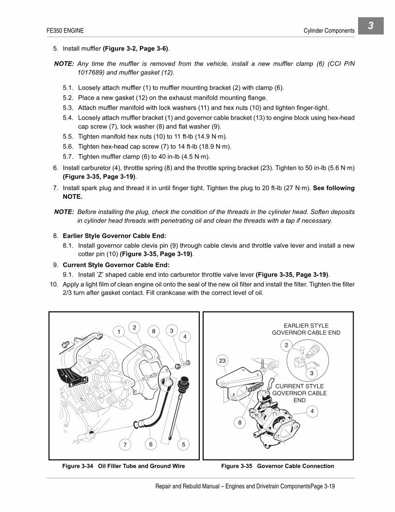
FE350 ENGINE Cylinder Components 3
5. Install muffler (Figure 3-2, Page 3-6).
NOTE: Any time the muffler is removed from the vehicle, install a new muffler clamp (6) (CCI P/N1017689) and muffler gasket (12).
5.1. Loosely attach muffler (1) to muffler mounting bracket (2) with clamp (6). 5.2. Place a new gasket (12) on the exhaust manifold mounting flange.5.3. Attach muffler manifold with lock washers (11) and hex nuts (10) and tighten finger-tight.5.4. Loosely attach muffler bracket (1) and governor cable bracket (13) to engine block using hex-head
cap screw (7), lock washer (8) and flat washer (9).5.5. Tighten manifold hex nuts (10) to 11 ft-lb (14.9 N·m).5.6. Tighten hex-head cap screw (7) to 14 ft-lb (18.9 N·m).5.7. Tighten muffler clamp (6) to 40 in-lb (4.5 N·m).
6. Install carburetor (4), throttle spring (8) and the throttle spring bracket (23). Tighten to 50 in-lb (5.6 N·m)(Figure 3-35, Page 3-19).
7. Install spark plug and thread it in until finger tight. Tighten the plug to 20 ft-lb (27 N·m). See followingNOTE.
NOTE: Before installing the plug, check the condition of the threads in the cylinder head. Soften depositsin cylinder head threads with penetrating oil and clean the threads with a tap if necessary.
8. Earlier Style Governor Cable End:8.1. Install governor cable clevis pin (9) through cable clevis and throttle valve lever and install a new
cotter pin (10) (Figure 3-35, Page 3-19).9. Current Style Governor Cable End:
9.1. Install ’Z’ shaped cable end into carburetor throttle valve lever (Figure 3-35, Page 3-19).10. Apply a light film of clean engine oil onto the seal of the new oil filter and install the filter. Tighten the filter
2/3 turn after gasket contact. Fill crankcase with the correct level of oil.
Figure 3-34 Oil Filler Tube and Ground Wire Figure 3-35 Governor Cable Connection
1
7 6 5
2 34
8
8
4
3
2
23
EARLIER STYLEGOVERNOR CABLE END
CURRENT STYLEGOVERNOR CABLE
END
Repair and Rebuild Manual – Engines and Drivetrain ComponentsPage 3-19

FE350 ENGINE Crankcase Components3
CRANKCASE COMPONENTS
See General Warning on page 1-1.If the crankcase needs to be disassembled, the following procedures will apply.
1. Remove items associated with the cylinder assembly. See Cylinder Shroud Removal on page 3-4.2. Remove crankcase oil drain plug. Tip the engine slightly to allow all of the oil to drain from the crankcase.
Dispose of engine oil properly.
CRANKCASE COVER REMOVAL1. Remove yellow jumper wire (11) from cord connector (12) (Figure 3-36, Page 3-20).2. Remove nuts and clamps at two-ended bolts (1 and 2) (Figure 3-37, Page 3-20)3. Remove eight bolts (3) and remove the crankcase cover (4) (Figure 3-37, Page 3-20). See following
NOTE.
NOTE: If the crankcase cover sticks, tap lightly with a plastic mallet on alternate sides near the dowel pins(5).
4. Remove the crankcase cover gasket completely.
Oil Level Sensor Removal
NOTE: It is recommended that the oil level sensor be replaced with a new one.
1. Disconnect the oil level sensor wire (2) from the cord connector (1) (Figure 3-38, Page 3-21).2. Remove screw (3) from the wire clamp (4).3. Remove the two mounting screws (8) from inside of the crankcase cover and remove the oil level sensor
and bracket.
4. Remove the three screws (7) holding the sensor (6).
Figure 3-36 Oil Level Sensor Wire Figure 3-37 Crankcase Cover
STARTER/GENERATOR
12
11
3
4
1
2
55
Page 3-20Repair and Rebuild Manual – Engines and Drivetrain Components

FE350 ENGINE Crankcase Components 3
Oil Level Sensor Installation1. Install a new sensor (6) into bracket (5) and secure with three screws (7) and tighten to 17 in-lb (1.9 N·m)
(Figure 3-38, Page 3-21).2. Position the sensor and bracket on inside of crankcase and install two mounting screws (8).
3. Connect sensor wire (2) to cord connector (1).
4. Install screw (3) through wire clamp and into crankcase cover. Tighten to 30 in-lb (3.4 N·m).
CAMSHAFT AND HYDRAULIC LIFTERSCamshaft and Hydraulic Lifter InspectionIf the engine typically has remained noisy for two minutes after starting, the hydraulic lifters might be wornbetween the plunger (2) and the body (3). Proceed with the following to check the hydraulic lifter for wear(Figure 3-40, Page 3-21).
1. Put the hydraulic lifter vertically on a measuring stand to measure leak-down distance.
2. Push the socket (1) down and measure the distance that it sinks (Figure 3-40, Page 3-21).3. If the distance exceeds 0.0197 inch (0.5 mm), replace both hydraulic lifters as a set.
Figure 3-38 Oil Level Sensor Figure 3-39 Timing Mark Alignment
Figure 3-40 Inspect for Hydraulic Lifter Wear Figure 3-41 Measure O.D. of Camshaft Journals
TYPICAL 2 PLACES
TYPICAL 3 PLACES
1
4
3
2
9 8
5 6
7
AA
1
2
3
Measure in 2 places,90 apart.
Repair and Rebuild Manual – Engines and Drivetrain ComponentsPage 3-21

FE350 ENGINE Crankcase Components3
4. Inspect the camshaft for wear or broken gear teeth.
5. Measure the camshaft journals and cam lobes with a micrometer at the points shown (Figure 3-41,Page 3-21 and Figure 3-42, Page 3-23).
6. If the camshaft journal diameter is less than 0.9026 inch (22.927 mm) at either end of the shaft, replacethe camshaft.
7. If the lobe height is less than 1.3086 inches (33.24 mm) for either lobe, replace the camshaft.
8. Key-Start Engines:
8.1. Check the automatic compression release valve (ACR) arms to make sure they move freely andare not binding. Clean the arms if needed. Make sure the take-up spring is properly installed.Replace the spring if it is broken. If the arms are damaged, the camshaft assembly must bereplaced.
Camshaft and Hydraulic Lifter Removal1. Keep the timing marks (A) aligned during removal (Figure 3-39, Page 3-21).
2. With cylinder head removed, pull the hydraulic lifters out of their bores to the top of the cylinder. SeeRocker Arm and Push Rod Removal on page 3-7. See following CAUTION.
CAUTION
• Do not press the socket (1) (Figure 3-40, Page 3-21). This will cause the engine oil to leak outof the high pressure chamber during storage. Keep the hydraulic lifters upright to prevent theengine oil from spilling out of the lifters during storage.
• Do not attempt to disassemble a hydraulic lifter because the engine oil will drain out of thehigh pressure chamber in the lifter.
3. Take the camshaft out of the engine block.
Automatic Compression Release Valve (ACR) InspectionPedal-Start Engines: FE350 engines on pedal-start vehicles do not have automatic compressionrelease valves (ACR).
Key-Start Engines: FE350 key-start engines have an automatic compression release valve (ACR)that is activated during the starting procedure (Figure 3-43, Page 3-23). As the engine is cranked at anormal 550 to 600 RPM, the ACR opens and reduces compression in the cylinder, allowing the starterto turn the engine with a minimal amount of starter energy and helping to reduce starter/generatorbrush wear. A tapping noise will be heard while the ACR is in an open condition. It is normal for theACR to click, or tap, during normal cranking RPM. When the engine starts and accelerates to 700RPM, the ACR will close, the tapping noise will stop, and full compression will be reached. After theengine starts, it will idle at 1150 to 1200 RPM.
If the ACR fails to hold the valve open during the cranking function, the engine will have too much com-pression and may not turn over when the starter is activated. If, after the engine starts and reaches 700RPM, the ACR fails to allow the exhaust valve to close, the engine will not reach required running com-pression and will not have complete acceleration power. The return spring on the ACR is the only ser-viceable part. The ACR is a component part of the camshaft assembly and if the ACR fails, thecamshaft assembly must be replaced.
Page 3-22Repair and Rebuild Manual – Engines and Drivetrain Components

FE350 ENGINE Piston and Connecting Rod 3
Camshaft and Hydraulic Lifter Installation
CAUTION
• When installing the camshaft, make sure that the tang (1) on the oil pump rotor seats in theslot (2) in end of the camshaft (Figure 3-42, Page 3-23 or Figure 3-94, Page 3-43). If the oilpump tang is not seated in the slot in the camshaft, serious engine damage will result.
1. Installation is the reverse of removal. See Camshaft and Hydraulic Lifter Removal on page 3-22.
2. Apply a light film of engine oil to the camshaft journals and cam lobes.
3. Align the timing marks (3) (Figure 3-39, Page 3-21). See following NOTE.
NOTE: If the outside edges of the camshaft and crankshaft gears are not flush, and the crankcase coverwill not easily make full contact with the crankcase, make sure the tang on the oil pump rotor isseated in the camshaft slot.
PISTON AND CONNECTING ROD
See General Warning on page 1-1.
NOTE: The connecting rod and cap must stay together as a set. Do not mix parts from any other engine.
Piston and Connecting Rod Removal1. Turn crankshaft to expose the two connecting rod cap bolts (1) (Figure 3-44, Page 3-24).
2. Loosen the cap bolts and take them out together with the connecting rod cap (2).
3. Push the piston/connecting rod assembly out of the cylinder.
Piston and Connecting Rod Separation1. Remove the two retaining rings holding the piston pin in place.
2. Remove the piston pin.
Figure 3-42 Measure O.D. of Camlobes Figure 3-43 ACR Valve Inspection
010
2030
01
23
45
67
89
1011
4050
6070
80
OIL PUMPTANG SLOT
AUTOMATICCOMPRESSIONRELEASEVALVE
CAMSHAFT
Repair and Rebuild Manual – Engines and Drivetrain ComponentsPage 3-23

FE350 ENGINE Piston and Connecting Rod3
Piston Inspection and Repair1. Remove all deposits from the piston.
2. Clean the carbon from the piston ring grooves. See following CAUTION.
CAUTION
• Never clean the piston head with the engine assembled. Carbon particles will fall between thepiston and cylinder wall and may cause severe cylinder wear.
3. Be sure the oil return passages in the ring grooves are open.
4. Visually inspect the piston rings and ring grooves for uneven wear or damage. Replace the piston and/or piston rings if uneven wear or damage is present or if they exceed the wear limits.
5. Use a new piston ring and feeler gauge to measure the clearance between the grooves and ring at sev-eral points around the grooves (Figure 3-45, Page 3-24).
6. If the top groove has a clearance greater than 0.0063 inch (0.16 mm), replace the piston.
7. If the second groove has a clearance greater than 0.0055 inch (0.14 mm), replace the piston.
8. The oil ring is made of three pieces: upper and lower rails and expander. It is difficult to measure the ringgroove clearance and thickness. Inspect visually for wear or damage.
Piston Ring Inspection1. Insert the ring squarely into the cylinder bore to a point approximately 1 inch (25 mm) down from the top
the cylinder. See following NOTE.
NOTE: Use the top of the piston to push the ring into the bore to be sure it is square.
2. Use a feeler gauge to measure the ring end-gap (Figure 3-46, Page 3-25).
3. If the end-gap of any ring is greater than 0.0472 inch (1.199 mm), replace the entire set of rings.
4. Use a micrometer to measure the thickness of both piston rings at several points around the rings(Figure 3-47, Page 3-25).
5. If either ring thickness is less than 0.0566 inch (1.438 mm), replace the entire set of rings. See followingNOTE.
Figure 3-44 Connecting Rod Cap Bolts Figure 3-45 Measure Piston Ring Clearance
1
2
Page 3-24Repair and Rebuild Manual – Engines and Drivetrain Components

FE350 ENGINE Piston and Connecting Rod 3
NOTE: It is difficult to measure the exact thickness of the the oil ring. Replace the oil ring whenever thecompression rings (top and second) are replaced.
If a chrome ring is included as part of the ring set, always assemble it into the top piston groove.
Piston Pin Inspection1. Use a micrometer to measure the outside diameter of the piston pin at several points along its length
(Figure 3-48, Page 3-25).
2. If the pin diameter is smaller than 0.7864 inch (19.975 mm), replace the piston pin.
3. Use an inside micrometer or telescoping gauge to measure the inside diameter of the piston pin hole inthe piston at several points (Figure 3-49, Page 3-25).
4. If the inside diameter exceeds 0.7887 inch (20.033 mm), replace the piston.
Connecting Rod Inspection
1. Clean and inspect the bearing surfaces of the connecting rod and cap. Replace parts if scored.
2. Use a telescoping gauge to measure the inside diameter of the connecting rod small bore at severalpoints along its length (Figure 3-50, Page 3-26).
Figure 3-46 Measure Ring End-Gap Figure 3-47 Measure Piston Ring Thickness
Figure 3-48 Measure O.D. of Piston Pin Figure 3-49 Measure I.D. of Piston Pin Hole
A
B
C
D
E
A2
A1
Measure each positionin 2 places, 90 apart.
A
B
C
D D
C
B
A11
11
11
11
A A21
Measure eachposition
in 2 places,90 apart.
Repair and Rebuild Manual – Engines and Drivetrain ComponentsPage 3-25

FE350 ENGINE Cylinder Block3
3. If the inside diameter exceeds 0.7887 inch (20.033 mm), replace the connecting rod.
4. Remount the connecting rod cap to the connecting rod at the large bore end, aligning the pilot groove onthe rod. Screw in the connecting rod bolts and tighten them to 16.5 ft-lb (23 N·m).
5. Use a telescoping gauge or an inside micrometer to measure the inside diameter of the large bore at sev-eral points along its length (Figure 3-51, Page 3-26).
6. If the inside diameter exceeds 1.479 inches (37.567 mm), replace the connecting rod. See followingNOTE.
NOTE: If the connecting rod is bent or twisted, it must be replaced.
CAUTION
• The connecting rod and cap must stay together as a set. Do not mix parts from any otherengine.
Piston and Connecting Rod Installation
See Piston and Connecting Rod Installation on page 3-41.
CYLINDER BLOCK
See General Warning on page 1-1.
While the engine is disassembled, inspect the cylinder block for cracks, stripped bolt holes, broken fins, or cyl-inder wall scoring. Repair or replace as necessary.
1. Use an inside micrometer or telescoping gauge, together with a micrometer, to measure the cylinderbore.
Figure 3-50 Measure I.D. of Connecting Rod Small Bore
Figure 3-51 Measure I.D. of Connecting Rod Large Bore
A A21Measure each
position in2 places,90 apart.
A A21
Measure eachposition in2 places,90 apart.
Page 3-26Repair and Rebuild Manual – Engines and Drivetrain Components

FE350 ENGINE Cylinder Block 3
2. Make the first measurement parallel with the crankshaft and the second at right angles to the crankshaftat three different locations in the bore. The first measurement location is 0.4 inch (10 mm) from the topof the cylinder. The second location is in the center or 2.4 inches (60 mm) from the top, and the third loca-tion is 0.3 inch (8 mm) from the bottom of the cylinder or bottom of ring travel. (See locations 1, 2, and3 in Figure 3-52, Page 3-27).
3. Engine Bore Dimensions: FE3503.1. The standard bore diameter is 3.2669 - 3.2677 inches (82.980 - 83.000 mm).3.2. The maximum cylinder bore diameter wear limit is 3.2703 inches (83.067 mm).3.3. The maximum acceptable out of round cylinder bore is 0.0022 inches (0.056 mm).
4. If the cylinder bore is not within these measurements, the cylinder bore will need to be resized whereapplicable.
To Resize Bore to Next OversizeAlways resize the bore to exactly 0.020 inches (0.50 mm) over standard size.
1. The bore size 0.020 inches over standard size is 3.2858 - 3.2866 inches (83.460 - 83.480 mm). SeeSpecifications for Resizing Cylinder Bore on page 3-48. See following NOTE.
NOTE: Allow for shrinkage (from the final size) of 0.0003 - 0.0004 inches (0.0007 - 0.0009 mm), which willoccur when the cylinder cools down.
2. Hone the cylinder to the final bore diameter of 3.2866 - 3.2874 inches (83.480 - 83.500 mm). See Spec-ifications for Resizing Cylinder Bore on page 3-48. See following NOTE.
NOTE: The cylinder wall finish should have a 40° to 60° cross-hatch pattern (Figure 3-53, Page 3-27).
Do not use solvents or gasoline to clean cylinder after honing. Solvents and gasoline allow thegrindings to remain in the honed surface and will not provide a surface suited for ring seating.
3. After honing, clean the cylinder wall thoroughly using soap, warm water and clean rags. See followingCAUTION.
CAUTION
• The cylinder must be thoroughly cleaned after honing to eliminate all grit.
4. Dry the cylinder and coat with engine oil.
Figure 3-52 Measure Cylinder Bore Figure 3-53 Hone Cylinder
3 1
3 2
Measure each bore in 2 places 90 apart.
1
2
3
HONING TOOL
Repair and Rebuild Manual – Engines and Drivetrain ComponentsPage 3-27

FE350 ENGINE Ignition Coil and Flywheel3
IGNITION COIL AND FLYWHEEL
See General Warning on page 1-1.Ignition Coil and Flywheel Removal
1. Loosen three screws and remove the remaining four screws attaching the flywheel housing, then removethe housing (Figure 3-54, Page 3-28).
2. Disconnect the ignition coil (1) from its primary lead wire at the connector (2). Remove the two bolts (3)and remove the ignition coil (Figure 3-55, Page 3-28).
3. Hold the flywheel (4), not the fan (7), with a strap wrench (5) and use a 25 mm socket to remove the fly-wheel nut (and flat washer) by turning it counterclockwise (Figure 3-56, Page 3-29). See followingCAUTION.
CAUTION
• The flywheel nut has right-hand threads. Turn it clockwise to tighten, or counterclockwise toloosen.
• Do not damage the fan blades with the strap wrench. Do not place screwdriver or pry bar inthe fan blades.
4. Remove the flywheel.
5. Remove the flywheel key from its groove.
Flywheel InstallationSee Engine Assembly on page 3-45.
Ignition Coil InstallationIt is recommended that the ignition coil (CCI P/N 101909201) be replaced with engine teardown.
1. Installation is the reverse of removal.
2. Lightly tighten the two bolts (3) while using a bronze feeler gauge to maintain the ignition coil air gap to0.012 inch (0.304 mm) (Figure 3-57, Page 3-29).
3. Tighten the two ignition coil bolts to 30 in-lb (3.4 N·m).
Figure 3-54 Flywheel Housing Figure 3-55 Ignition Coil
Loosen.
Remove.
Remove.
2
1
3
Page 3-28Repair and Rebuild Manual – Engines and Drivetrain Components

FE350 ENGINE Oil Pump 3
OIL PUMP
See General Warning on page 1-1.
Oil Pump Cover Removal1. Remove the six screws (1-6) and remove the oil pump cover (7) (Figure 3-58, Page 3-29).
2. Peel off the oil pump cover gasket (8).
3. Remove the pump gear cover plate (9) and filter screen (10).
Figure 3-56 Flywheel Nut Figure 3-57 Adjust Ignition Coil Air Gap
Figure 3-58 Oil Pump Removal Figure 3-59 Check Clearance Between Rotors
5
7
4 MF3
481
0.012 inch(0.304 mm)
3
TYPICAL 6
PLACES8
911
10
7
13
6
5 42
5
6
Repair and Rebuild Manual – Engines and Drivetrain ComponentsPage 3-29

FE350 ENGINE Oil Pump3
Oil Pump Inspection1. Check the clearance between the inner and outer rotors (5) with a feeler gauge (6). Measure the clear-
ance between the high point of the inner rotor and the high point of the outer rotor (Figure 3-59,Page 3-29).
2. Replace both rotors as a set if the measurement exceeds 0.012 inch (0.3 mm).
3. Remove inner and outer rotors (11) (Figure 3-58, Page 3-29).4. Inspect the inner and outer oil pump rotors. If the rotors are worn or damaged, replace them.
4.1. Measure the pump shaft bearing surface. Replace both rotors as a set if the measurement is lessthan 0.4971 inch (12.627 mm) (Figure 3-60, Page 3-30).
4.2. Use a micrometer to measure the diameter of the outer rotor at several points (Figure 3-61,Page 3-30).
4.3. If the rotor diameter is less than 1.5923 inches (40.467 mm), replace both rotors.4.4. Use a micrometer to measure the thickness of the outer rotor at several points (Figure 3-62,
Page 3-30).4.5. If the rotor thickness is less than 0.3905 inch (9.920 mm), replace both rotors.
Figure 3-60 Measure Pump Shaft Bearing Surface Figure 3-61 Measure O.D. of Outer Rotor
Figure 3-62 Measure Thickness of Outer Rotor
5
A
B
Measure two places, 90 apart. 5
A B
Measure twoplaces, 90 apart.
ABCDE
5
Page 3-30Repair and Rebuild Manual – Engines and Drivetrain Components

FE350 ENGINE Oil Pump 3
OIL PRESSURE RELIEF VALVE
Oil Pressure Relief Valve Removal
1. Remove the oil pump cover. See Oil Pump Cover Removal on page 3-29.
2. Remove the valve seat (1), ball (2) and spring (3) (Figure 3-63, Page 3-31).
Oil Pressure Relief Valve Inspection
1. Note the condition of the ball (2) and the valve seat (1). They must not have any nicks or burrs. Replaceif necessary (Figure 3-63, Page 3-31).
2. Inspect the relief valve spring (3) for pitting, cracks, rusting and burrs. Replace if necessary.
3. Measure free length of the spring (3) with a vernier caliper (Figure 3-64, Page 3-31). If the free lengthof the relief valve spring is less than 0.748 inches (19.00 mm), replace the spring.
Oil Pressure Relief Valve Installation
1. Installation is the reverse of removal. If necessary, put the ball in position and lightly tap with a plastichammer to form a perfect seat.
Oil Pump Installation
CAUTION
• Do not allow any dust or other foreign matter into the oil pump.
1. Installation is the reverse of removal.
2. Install the inner rotor with its tang in the slot in the end of the camshaft (Figure 3-65, Page 3-32).
3. Install six bolts (1-6) and finger-tighten. Then tighten to 7 ft-lb (9.5 N·m) in the sequence shown(Figure 3-58, Page 3-29). After tightening bolts, check the torque of the first bolt.
Figure 3-63 Oil Pressure Relief Valve Figure 3-64 Measure Free Length of Spring
1
32
OILPUMP
0
010
1020
2030
3040
405050
60
60
70
7080
80
90
90
3
Repair and Rebuild Manual – Engines and Drivetrain ComponentsPage 3-31

FE350 ENGINECrankshaft and Counterbalance3
CRANKSHAFT AND COUNTERBALANCE
See General Warning on page 1-1.Crankshaft and Counterbalance Removal
1. Remove the four nuts (1) and pull out the counterbalance guide shaft (2) and the O-ring (3) (Figure 3-66,Page 3-32).
2. Pull out the crankshaft and the counterbalance together as an assembly (Figure 3-67, Page 3-32).
Crankshaft and Counterbalance Disassembly1. Slide the spacer (2) and the link rod (3) off the flywheel end of the crankshaft. Remove the counterbal-
ance from the remaining link rod (Figure 3-67, Page 3-32). Go to Link Rod Inspection on page 3-34.
2. If the link rods need replacing, place the gear yoke (CCI P/N 1016418) under the spur gear with the smallend of the connecting rod located opposite the crankpin (Figure 3-68, Page 3-33).
Figure 3-65 Install Inner Rotor
Figure 3-66 Counterbalance Guide Shaft and O-Ring Figure 3-67 Crankshaft and Counterbalance
TANG
6
SLOT
5
2
1
3
2
3
Page 3-32Repair and Rebuild Manual – Engines and Drivetrain Components

FE350 ENGINECrankshaft and Counterbalance 3
3. Position the gear yoke with the side blocks positioned as close to the crankshaft as possible(Figure 3-69, Page 3-33).
4. Use a press and push on the end of the crankshaft to pull the spur gear and the helical gear off the crank-shaft. See following WARNING and CAUTION.
ý WARNING
• Support the crankshaft while pressing. This will prevent the crankshaft from dropping to thefloor after the gear has been removed.
CAUTION
• Always use a press when removing the spur gear and helical gear from, or installing them on,the crankshaft.
5. Remove the woodruff key.
6. Slide the remaining link rod off the crankshaft.
Figure 3-68 Place Assembly in Press Figure 3-69 Remove Helical and Spur Gears
HELICAL GEARGEAR YOKE
SPUR GEAR
SIDE BLOCKS (2)
PRESSTABLE
PRESS RAM
PRESSTABLE
GEAR YOKE
SIDE BLOCKS
Repair and Rebuild Manual – Engines and Drivetrain ComponentsPage 3-33

FE350 ENGINECrankshaft and Counterbalance3
Link Rod Inspection
1. Clean and inspect the link rod (1) bearing surfaces. If the bearing surface of the small end is scored ordamaged, replace the link rod. If the large end bearing is scored or damaged, the link rod must bereplaced (Figure 3-70, Page 3-34).
1.1. Use a telescoping gauge and micrometer to measure both inside bearing surfaces at severalpoints.
1.2. If the inside diameter of the small end is greater than 0.4746 inch (12.057 mm), replace the link rod(Figure 3-71, Page 3-34).
1.3. If the inside diameter of the large end is greater than 1.9726 inches (50.106 mm), replace the linkrod (Figure 3-72, Page 3-34). See following NOTE.
NOTE: Do not remove the link rod on the PTO (power take-off) side unless link rod on the opposite endneeds replacement. The crank-gear is very tightly fitted to the crankshaft so that it can transferengine torque to the camshaft. Ignore Crankshaft and Counterbalance Disassembly (steps 2through 6, page 3-32), if the link rod opposite of the PTO side passes inspection (Figure 3-70,Page 3-34).
Figure 3-70 Inspect Link Rod Figure 3-71 Measure Link Rod Small Bore I.D.
Figure 3-72 Measure Link Rod Large Bore I.D
1
TYPICAL 4 PLACES
A A21Measure in two places,
90 apart.
A A21Measure each position in 2
places, 90 apart.
Page 3-34Repair and Rebuild Manual – Engines and Drivetrain Components

FE350 ENGINECrankshaft and Counterbalance 3
COUNTERBALANCE WEIGHT
NOTE: The wrist pins are tightly pressed into the weight and normally require no maintenance.
Counterbalance Weight Inspection1. Clean the inside bearing surface and inspect it for wear or damage.
2. Use a telescoping gauge and micrometer to measure the inside diameter of the bearing surface(Figure 3-73, Page 3-35).
3. If the inside diameter is greater than 1.0274 inches (26.097 mm), or the bore shows signs of wear ordamage, replace the counterbalance weight.
Counterbalance Weight Bearing Replacement1. Support the weight around the bearing hole and drive the bearing out of the counterbalance weight with
a bearing drive. See following NOTE.
NOTE: Install the new bearing with its oil hole aligned with the oil passage in the counterbalance weight.
2. Clean the parts thoroughly in a high flash-point solvent and wipe dry.
3. Coat new bearing with clean engine oil.
4. Press the new bearing into the counterbalance weight.
Counterbalance Guide Shaft Inspection1. Clean the shaft surface and inspect it for wear or damage.
2. Use an outside micrometer to measure the outside diameter of the guide shaft surface (Figure 3-74,Page 3-35).
3. If the outside diameter is smaller than 1.0593 inches (25.907 mm), or the shaft shows signs of wear ordamage, replace the guide shaft.
4. Check the O-ring seal to make sure the O-ring is not damaged. Replace if necessary.
Figure 3-73 Measure I.D. of CourterbalanceWeight Bore
Figure 3-74 Measure O.D. of Counterbalance Guide Shaft
A A21
Measure eachposition in two
places, 90 apart.
Measure each position in 2 places, 90 apart.
A
B
C
D D
C
B
A11
11
11
11
A2
A1
Repair and Rebuild Manual – Engines and Drivetrain ComponentsPage 3-35

FE350 ENGINECrankshaft and Counterbalance3
Crankshaft Inspection
NOTE: The crankshaft for a unitized (clockwise) engine has left-hand threads at the clutch mounting hole,and there is a machined groove in the outside diameter of the counterweight as shown.(Figure 3-75, Page 3-36).
1. Clean and inspect the journals for scoring. Inspect the crankshaft gear for cracks, scoring or brokenteeth. Replace parts if necessary.
2. Use a micrometer to measure both main journals at several points along their lengths (Figure 3-76,Page 3-36).
3. If either journal diameter is less than 1.3752 inches (34.930 mm), replace the crankshaft.
4. Use a micrometer to measure the connecting rod journal at several points along its length (Figure 3-77,Page 3-36).
5. If the journal diameter is less than 1.4742 inches (37.444 mm), replace the crankshaft.
6. Use a micrometer to measure crankshaft link rod journals at several points (Figure 3-78, Page 3-36).
Figure 3-75 Crankshaft Inspection Figure 3-76 Measure Crankshaft Journals
Figure 3-77 Measure Connecting Rod Journal Figure 3-78 Measure Link Rod Journals
Groove machined into the outside diameter of the counterweight
UNITIZED(CLOCKWISE)CRANKSHAFT
A2
A1
Measure each positionin 2 places, 90 apart.
A
B
C
D D
C
B
A11
11
11
11
A1
A2
A
B
C C
B
A11
11
11
Measure each positionin 2 places, 90 apart.
A2
A1
Measure each positionin 2 places, 90 apart.
Page 3-36Repair and Rebuild Manual – Engines and Drivetrain Components
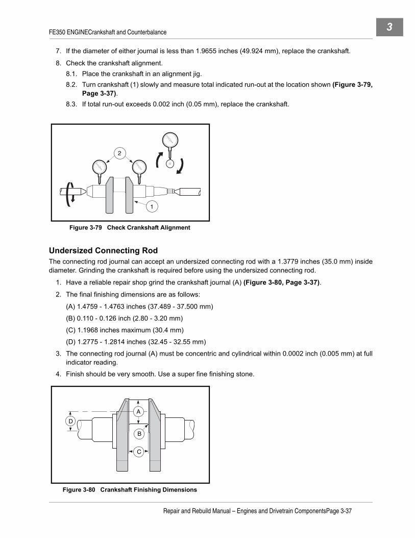
FE350 ENGINECrankshaft and Counterbalance 3
7. If the diameter of either journal is less than 1.9655 inches (49.924 mm), replace the crankshaft.
8. Check the crankshaft alignment.8.1. Place the crankshaft in an alignment jig.8.2. Turn crankshaft (1) slowly and measure total indicated run-out at the location shown (Figure 3-79,
Page 3-37).8.3. If total run-out exceeds 0.002 inch (0.05 mm), replace the crankshaft.
Undersized Connecting RodThe connecting rod journal can accept an undersized connecting rod with a 1.3779 inches (35.0 mm) insidediameter. Grinding the crankshaft is required before using the undersized connecting rod.
1. Have a reliable repair shop grind the crankshaft journal (A) (Figure 3-80, Page 3-37).
2. The final finishing dimensions are as follows:
(A) 1.4759 - 1.4763 inches (37.489 - 37.500 mm)
(B) 0.110 - 0.126 inch (2.80 - 3.20 mm)
(C) 1.1968 inches maximum (30.4 mm)
(D) 1.2775 - 1.2814 inches (32.45 - 32.55 mm)
3. The connecting rod journal (A) must be concentric and cylindrical within 0.0002 inch (0.005 mm) at fullindicator reading.
4. Finish should be very smooth. Use a super fine finishing stone.
Figure 3-79 Check Crankshaft Alignment
Figure 3-80 Crankshaft Finishing Dimensions
2
1
C
B
A
D
Repair and Rebuild Manual – Engines and Drivetrain ComponentsPage 3-37

FE350 ENGINECrankshaft and Counterbalance3
OIL SCREEN
Oil Screen Removal1. Remove the two bolts (1) to take out the oil screen plate (2) and the oil screen (3) (Figure 3-81,
Page 3-38).
2. Clean the oil screen thoroughly with a high flash-point solvent and dry it.
Oil Screen Installation1. Installation is the reverse of removal.
2. Tighten bolts (1) to 30 in-lb (3.4 N·m).
BALL BEARING
Ball Bearing Removal1. Remove the oil seal in the crankcase cover. See following NOTE.
NOTE: Never reuse an oil seal. Replace the oil seal with a new one.
2. Place the crankcase cover (1) on a bench with its outside up (gasket surface against bench)(Figure 3-82, Page 3-38).
3. Use a bearing driver (2) (part of Bearing Driver Kit, CCI P/N 1016416) to drive out the ball bearing (3).
Ball Bearing Inspection1. Clean the ball bearing thoroughly in high flash-point solvent and dry it.
NOTE: Never use compressed air to dry bearing. Spinning the bearing at accelerated speeds withoutlubrication can damage both the bearings and bearing seat and result in premature bearing failure.
2. Spin the ball bearing by hand and check for (A) axial play and (B) radial play. Replace the ball bearingif it is noisy, does not spin smoothly, or if it has any play (Figure 3-83, Page 3-39).
Figure 3-81 Oil Screen Removal Figure 3-82 Ball Bearing Removal
3
1
2
1
2
3
Page 3-38Repair and Rebuild Manual – Engines and Drivetrain Components

FE350 ENGINECrankshaft and Counterbalance 3
OIL SEALS
Oil seals are used on both ends of the crankshaft. Any time the crankshaft is removed from the seals, theseals must be replaced with new ones.
Oil Seal Removal
Use an oil seal remover to press or drive the seal out of the casing.
Oil Seal Installation
NOTE: Never reuse an oil seal. Always replace the oil seal with a new one.
1. Put a light coating of clean engine oil on the outside edge and the inner lip of the oil seal to assist instal-lation.
2. Install all oil seals with their lips facing the center of the engine.
3. Use the 1.37 inch (35 mm) seal driver to press the oil seal into the flywheel side of the crankcase untilit is flush with the hole.
4. Use the 1.97 inch (50 mm) seal driver to press the oil seal into the crankcase cover until it is 0.157 inch(4 mm) below the outside surface.
Plain Bearing Surface Inspection
Plain bearing surfaces are used for both ends of the camshaft and the flywheel end of the crankshaft.
1. Inspect the camshaft surfaces, one in the crankcase (3) (Figure 3-87, Page 3-41) and the other in thecrankcase cover (1) (Figure 3-88, Page 3-41). Use an inside micrometer or telescoping gauge to mea-sure the inside diameter of each bearing surface. If the inside diameter is greater than 0.9080 inch(23.063 mm), replace the crankcase and/or the crankcase cover.
2. Inspect the crankshaft bearing surface (2) in the crankcase. Use an inside micrometer or telescopinggauge to measure the inside diameter of the bearing surface. If the inside diameter is greater than 1.1841inch (30.075 mm), replace the crankcase (Figure 3-87, Page 3-41).
Figure 3-83 Check Ball Bearing Figure 3-84 Inspect Bearing Surfaces in Crankcase
A
B
3
2
Repair and Rebuild Manual – Engines and Drivetrain ComponentsPage 3-39

FE350 ENGINECrankshaft and Counterbalance3
Crankshaft Installation
CAUTION
• Before assembly, make sure all parts are clean.
NOTE: When assembling the crankshaft and the counterbalance weight, apply a light film of engine oil tothe crankshaft journals and guide shaft (Figure 3-86, Page 3-40).
1. Installation is the reverse of removal. See Crankshaft and Counterbalance Removal on page 3-32.
2. Tighten the four nuts (1) for counterbalance guide shaft to 50 in-lb (5.9 N·m) (Figure 3-66, Page 3-32).
3. If the link rod was removed from the PTO side of the crankshaft, support the crankweb as shown, slidethe link rod onto the crankshaft, and install the key. Press the spur gear and helical gear onto the crank-shaft (Figure 3-89, Page 3-41 and Figure 3-90, Page 3-41). See following CAUTION and NOTE.
CAUTION
• Always use a press when removing or installing the spur gear and helical gear on thecrankshaft.
• If the spur gear was warped while being removed, install a new one.
NOTE: Make sure the chamfered inside diameters of the spur gear and helical gear are oriented down-ward on the crankshaft as shown (Figure 3-89, Page 3-41).
Make sure the link rods rotate smoothly after the gears are pressed on.
4. Slide the link rod, then the spacer, onto the flywheel end of the crankshaft.
Figure 3-85 Inspect Camshaft Bearing Surfacein Crankcase Cover
Figure 3-86 Crankshaft Assembly
1
POSITION SLIGHTLY CHAMFEREDEDGE TO INSIDE
CHAMFEREDINSIDE DIAMETER
1
2
3
Page 3-40Repair and Rebuild Manual – Engines and Drivetrain Components

FE350 ENGINECrankshaft and Counterbalance 3
PISTON AND CONNECTING ROD INSTALLATION1. Installation is the reverse of removal.
2. Assemble the piston and the connecting rod into a unit, if disassembled. Align the L mark (1) on the pis-ton head toward the lettering MADE IN JAPAN (2) on the connecting rod (Figure 3-91, Page 3-42).
3. Apply a light film of engine oil to the connecting rod bearing surfaces and the two connecting rod bolts.
4. Place the piston/connecting rod into the cylinder bore with the lettering MADE IN JAPAN on the connect-ing rod oriented toward the flywheel side of the engine. Position piston ring gaps so that they are orientedtoward the corresponding letters (Figure 3-92, Page 3-42): (A) Top Ring Gap, (B) Second Ring Gap, (C)Upper Side Rail Gap, (D) Lower Side Rail Gap.
NOTE: The letter R marked on the top two piston rings should be facing up when the rings are installed.
Install the chrome-edged ring into the top ring groove.
5. Tighten the two connecting rod bolts to 16.5 ft-lb (23 N·m).
Figure 3-87 Crankshaft Installation Figure 3-88 Press on Spur Gear and Helical Gear
Figure 3-89 Piston Head and Connecting RodAlignment
Figure 3-90 Piston Ring Gap Alignment
PRESSSLEEVE
PRESSTABLE
SPUR GEAR (CHAMFERED FACING DOWN)
LINK ROD
KEY
HELICAL GEAR(NOTE TIMING MARK) PRESS RAM
R
L
MADE IN JAPAN
MADE IN JAPAN
MADE IN JAPAN
MADE IN JAPAN
12
A
C
D
B
30-45
CRANK SHAFTCENTER LINE
Repair and Rebuild Manual – Engines and Drivetrain ComponentsPage 3-41
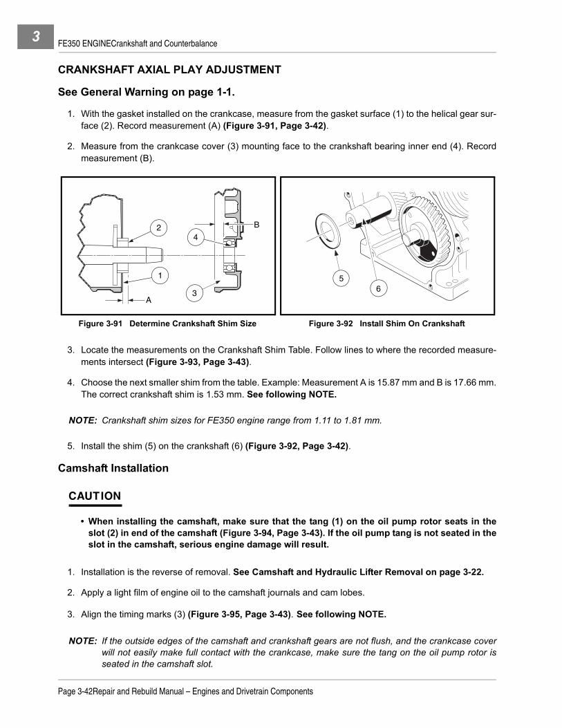
FE350 ENGINECrankshaft and Counterbalance3
CRANKSHAFT AXIAL PLAY ADJUSTMENT
See General Warning on page 1-1.
1. With the gasket installed on the crankcase, measure from the gasket surface (1) to the helical gear sur-face (2). Record measurement (A) (Figure 3-91, Page 3-42).
2. Measure from the crankcase cover (3) mounting face to the crankshaft bearing inner end (4). Recordmeasurement (B).
3. Locate the measurements on the Crankshaft Shim Table. Follow lines to where the recorded measure-ments intersect (Figure 3-93, Page 3-43).
4. Choose the next smaller shim from the table. Example: Measurement A is 15.87 mm and B is 17.66 mm.The correct crankshaft shim is 1.53 mm. See following NOTE.
NOTE: Crankshaft shim sizes for FE350 engine range from 1.11 to 1.81 mm.
5. Install the shim (5) on the crankshaft (6) (Figure 3-92, Page 3-42).
Camshaft Installation
CAUTION
• When installing the camshaft, make sure that the tang (1) on the oil pump rotor seats in theslot (2) in end of the camshaft (Figure 3-94, Page 3-43). If the oil pump tang is not seated in theslot in the camshaft, serious engine damage will result.
1. Installation is the reverse of removal. See Camshaft and Hydraulic Lifter Removal on page 3-22.
2. Apply a light film of engine oil to the camshaft journals and cam lobes.
3. Align the timing marks (3) (Figure 3-95, Page 3-43). See following NOTE.
NOTE: If the outside edges of the camshaft and crankshaft gears are not flush, and the crankcase coverwill not easily make full contact with the crankcase, make sure the tang on the oil pump rotor isseated in the camshaft slot.
Figure 3-91 Determine Crankshaft Shim Size Figure 3-92 Install Shim On Crankshaft
A
2 B
1
4
3
56
Page 3-42Repair and Rebuild Manual – Engines and Drivetrain Components

FE350 ENGINECrankshaft and Counterbalance 3
CAMSHAFT AXIAL PLAY ADJUSTMENT1. With the gasket (1) installed on the crankcase, measure from the gasket surface to the camgear surface
(2). Record this measurement (A) (Figure 3-96, Page 3-44).2. Measure from the crankcase cover (3) mounting face to the camshaft bearing inner end (4). Record this
measurement (B).3. Locate the measurements on the Camshaft Shim Table. Follow the lines to where the recorded mea-
surements intersect (Figure 3-98, Page 3-44).4. Choose the next smaller shim from the table. Example: Measurement A is 13.41 mm and B is 14.09 mm.
The correct camshaft shim is 0.4 mm.5. Install the shim (1) on the camshaft (2) (Figure 3-97, Page 3-44).
Figure 3-93 Crankshaft Shim Table
Figure 3-94 Proper Seating of Tang into Camshaft Slot
Figure 3-95 Align Timing Marks between Camshaft and Crankshaft
Mea
sure
men
t (B
)17.8317.8217.8117.8017.7917.7817.7717.7617.7517.7417.7317.7217.7117.7017.6917.6817.6717.6617.6517.6417.6317.6217.6117.6017.59
15.75 15.80 15.85 15.90 15.95 16.00 16.05 16.10 16.15 16.20 16.25
Measurement (A) Measurements in mm
1.74
1.74
1.67
1.67
1.60
1.60
1.53
1.53
1.46
1.46
1.39
1.39
1.32
1.32
1.25
1.25
1.18
1.18
1.74
1.67
1.60
1.53
1.46
1.39
1.32
1.25
1.11
1.11
1.11
1.18
1.81
1.81
1.81
2
1
3
Repair and Rebuild Manual – Engines and Drivetrain ComponentsPage 3-43

FE350 ENGINECrankshaft and Counterbalance3
CRANKCASE COVER INSTALLATION
CAUTION
• Before assembly, make sure parts are clean.• Do not reuse the gasket. Install a new one.• Install and tighten crankcase cover bolts as instructed. Failure to do so could cause the cover
to become warped.
1. Clean the gasket surfaces on the crankcase cover to fit a new gasket during installation and inspect theoil seal for wear and damage.
2. Install crankcase cover. Using HANDS ONLY, seat cover completely against the crankcase. If the coverwill not seat, the camshaft is not installed correctly.
3. Install and finger-tighten evenly the eight cover mounting bolts (Figure 3-99, Page 3-45).4. Tighten the cover mounting bolts in two steps. First, in the sequence shown, tighten all eight bolts to
approximately 130 in-lb (14 N·m). Then, repeating the sequence, tighten them to 250 in-lb (28.2 N·m).5. Connect the yellow jumper wire (11) to the cord connector (12) (Figure 3-36, Page 3-20).
Figure 3-96 Record These Measurements Figure 3-97 Shim Installation on Camshaft
Figure 3-98 Camshaft Shim Table
B
A
2
3
4
1 1 2
14.15
14.10
14.05
13.35 13.45 13.55Measurement (A)
Mea
sure
men
t (B
)
t=0.
5
t=0.
4
t=0.
3
Measurements in MM
Page 3-44Repair and Rebuild Manual – Engines and Drivetrain Components
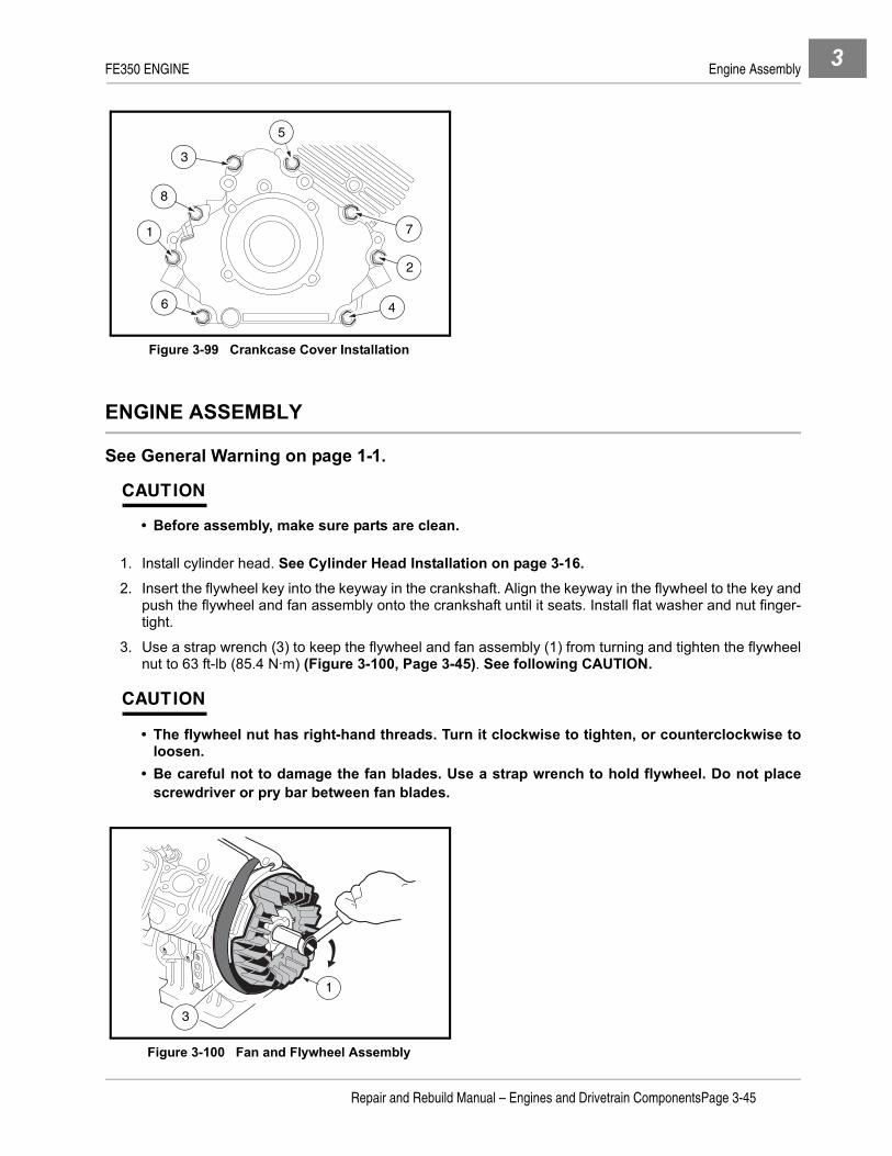
FE350 ENGINE Engine Assembly 3
ENGINE ASSEMBLY
See General Warning on page 1-1.
CAUTION
• Before assembly, make sure parts are clean.
1. Install cylinder head. See Cylinder Head Installation on page 3-16.2. Insert the flywheel key into the keyway in the crankshaft. Align the keyway in the flywheel to the key and
push the flywheel and fan assembly onto the crankshaft until it seats. Install flat washer and nut finger-tight.
3. Use a strap wrench (3) to keep the flywheel and fan assembly (1) from turning and tighten the flywheelnut to 63 ft-lb (85.4 N·m) (Figure 3-100, Page 3-45). See following CAUTION.
CAUTION
• The flywheel nut has right-hand threads. Turn it clockwise to tighten, or counterclockwise toloosen.
• Be careful not to damage the fan blades. Use a strap wrench to hold flywheel. Do not placescrewdriver or pry bar between fan blades.
Figure 3-99 Crankcase Cover Installation
Figure 3-100 Fan and Flywheel Assembly
3
5
8
1
6 4
2
7
1
3
MF3
481
Repair and Rebuild Manual – Engines and Drivetrain ComponentsPage 3-45

FE350 ENGINE Engine Installation3
4. Install ignition coil. See Ignition Coil Installation on page 3-28.5. Install all remaining engine components. See Installation of Remaining Engine Components on
page 3-18.6. Install a new spark plug, gap 0.027 - 0.031 inch (0.69 - 0.79 mm). Tighten to 20 ft-lb (27.12 N·m). See
following NOTE.
NOTE: Before installing the plug, check the condition of the threads in the cylinder head. Soften depositsin the cylinder head threads with penetrating oil and clean the threads with a tap if necessary.
7. Connect the spark plug wire.
ENGINE INSTALLATION
See Engine Installation in the appropriate maintenance and service manual.
Page 3-46Repair and Rebuild Manual – Engines and Drivetrain Components

FE350 ENGINE Service Specifications 3
SERVICE SPECIFICATIONS
ITEM SERVICE LIMIT FE350 ENGINE
Breather reed valve (valve tip air gap) 0.008 in. (0.2 mm) max.
Camshaft axial play 0.0137 in. (0.35 mm)
Camshaft bearing 0.9080 in. (23.063 mm) inner diameter max.
Camshaft cam lobes (exhaust, intake) 1.3086 in. (33.24 mm) outer diameter min.
Camshaft flywheel-side journal 0.9026 in. (22.927 mm) outer diameter min.
Camshaft PTO-side journal 0.9026 in. (22.927 mm) outer diameter min.
Connecting rod big-end bearing 1.4790 in. (37.567 mm) inner diameter max.
Connecting rod small-end bearing 0.7894 in. (20.051 mm) inner diameter max.
Counterbalance guide shaft 1.0199 in. (25.907 mm) outer diameter min.
Counterbalance weight bearing 1.0274 in. (26.097 mm) inner diameter max.
Counterbalancer link rod big-end bearing 1.9726 in. (50.106 mm) inner diameter max.
Counterbalancer link rod small-end bearing 0.4746 in. (12.057 mm) inner diameter max.
Crankcase cover camshaft bearing 0.9079 in. (23.063 mm) inner diameter max.
Crankshaft axial play 0.0137 in. (0.35 mm)
Crankshaft balancer – link-rod journals 1.9655 in. (49.924 mm) outer diameter min.
Crankshaft bearing 1.3809 in. (35.075 mm) inner diameter max.
Crankshaft crankpin journal 1.4741 in. (37.444 mm) outer diameter min.
Crankshaft flywheel- side journal 1.3751 in. (34.930 mm) outer diameter min.
Crankshaft PTO-side journal 1.3751 in. (34.930 mm) outer diameter min.
Cylinder bore (standard) 3.2669 to 3.2677 in. (82.980 to 83.000 mm)
Cylinder bore (maximum) 3.2703 in. (83.067 mm)
Cylinder bore (out of round) 0.022 in. (0.056 mm) max.
Oil pump housing 1.6050 in. (40.766 mm) inner diameter max.
Oil pump housing 0.4004 in. (10.170 mm) max.
Oil pump shaft 0.4971 in. (12.627 mm) outer diameter min.
Oil pump shaft bearing 0.5028 in. (12.770 mm) inner diameter max.
Outer rotor 1.5932 in. (40.467 mm) outer diameter min.
Outer rotor width 0.3905 in. (9.92 mm) min.
Piston oil-ring groove clearance and end gap Visual inspection only
Piston pin 0.7864 in. (19.975 mm) outer diameter min.
Piston pin hole 0.7887 in. (20.033 mm) inner diameter max.
Piston second ring groove clearance (with new ring) 0.0055 in. (0.14 mm) max.
Piston top ring groove clearance (with new ring) 0.0063 in. (0.16 mm) max.
Push rod (rod bend) 0.0196 in. (0.50mm) max.
Relief valve spring (free length) 0.748 in. (19.0 mm) min.
Rocker arm bearing 0.4754 in. (12.074 mm) inner diameter max.
Specifications continued on next page...
Repair and Rebuild Manual – Engines and Drivetrain ComponentsPage 3-47

FE350 ENGINE Service Specifications3
SPECIFICATIONS FOR RESIZING CYLINDER BORE
TORQUE SPECIFICATIONS
Rocker shaft 0.4704 in. (11.949 mm) outer diameter min.
Valve face angle (exhaust, intake) 45° (ex.), 30° (in.) standard
Valve guide (exhaust, intake) 0.2756 to 0.2762 in. (7.00 to 7.015 mm) inner diameter standard
Valve guide hole (exhaust) 0.2781 in. (7.065 mm) inner diameter max.
Valve guide hole (intake) 0.2781 in. (7.065 mm) inner diameter max.
Valve margin (exhaust, intake) 0.024 in. (0.6 mm) max.
Valve seat angle (exhaust, intake) 45° (Ex.), 30° (In.) standard
Valve seat width 0.0197 to 0.0433 in. (0.50 to 1.10mm) standard
Valve seat width 0.075 in. (1.9 mm) max.
Valve spring (free length) 1.5157 in. (38.50 mm) min.
Valve stem (exhaust) 0.2722 in. (6.915 mm) outer diameter min.
Valve stem (exhaust, intake) (stem bend) 0.0012 in. (0.03 mm) max.
Valve stem (intake) 0.2728 in. (6.930 mm) outer diameter min.
ITEM OVERSIZE FE350 LIMITS
Final boring bore diameter 0.020 in. (0.50 mm) 3.2877 in. (83.5075 mm)
Finished honed bore diameter 0.0034 in. (0.086 mm) 3.2903 in. (83.5736 mm)
ITEM SIZE FE350 LIMITS
Cylinder head bolts M8 17.5 ft-lb (24 N·m)
Connecting rod bolts(coat threads with engine oil) M7 16.5 ft-lb (23 N·m)
Flywheel retaining nut M18 100 ft-lb (135 N·m)
Crankcase cover to block bolts M8 22 ft-lb (31 N·m)
Starter/Generator bracket to block bolts M8 16.5 ft-lb (23 N·m)
Oil drain plug M14 16.5 ft-lb (23 N·m)
Fan housing screws M6 90 in-lb (10 N·m)
Fan shroud screws M6 25 in-lb (2.8 N·m)
Bolts marked with “4” (when used with nuts)
M8M6M5
130 in-lb (15 N·m)50 in-lb (5.9 N·m)30 in-lb (3.4 N·m)
ITEM SERVICE LIMIT FE350 ENGINE
Page 3-48Repair and Rebuild Manual – Engines and Drivetrain Components

FE350 ENGINE Service Specifications 3
ADJUSTMENT AND SETTINGS
ITEM SERVICE LIMITFE350 ENGINE
Spark plug gap (standard) 0.027 to 0.031 in. (0.69 to 0.79 mm)
Ignition coil air gap (standard) 0.012 in. (0.304 mm)
Oil pressure (min.) at fast idle speed 45.5 psi (3.14 Bars)
Oil filter: bypass-valve opening pressure 11.4 to 17.0 psi (.78 to 1.18 Bars)
Compression pressure (min.)(with automatic compression release) 71 psi (4.83 Bars)
Crankcase vacuum (min.) at fast idle speed 1.18 in. (30 mmHg)
Cylinder head-gasket surface flatness (max.) 0.002 in. (0.05 mm)
ACR lift (standard) 0.059 in. (1.5 mm)
ACR lift (min.) 0.0354 in. (0.9 mm)
Engine RPM 3800 (±30) RPM
Repair and Rebuild Manual – Engines and Drivetrain ComponentsPage 3-49

3

4
SECTION 4 – FE400 ENGINEý DANGER
• See General Warning on page 1-1.
ý WARNING
• See General Warning on page 1-1.
GENERAL INFORMATION
See General Warning on page 1-1.The FE400 gasoline engine is produced for one starting system: key-start. This 4-cycle, single cylinder engineis designed for reliable heavy-duty service. This engine has two major component assemblies: the cylinderassembly and the crankcase assembly.Servicing and teardown procedures for the FE400 are identical to the FE350 engine with a few exceptions. Allprocedures shown here for the FE400 engine are the exceptions from the FE350 procedures. Review theseprocedures carefully and note where they differ from the FE350.
Tools used to service these engines are also identical to the tools used for the FE350, with one exception: thepiston ring compressor sleeve; however, both the FE350 and FE400 piston ring compressor sleeves are pro-vided in the piston ring compressor kit (CCI P/N 1016414).
The FE400 engine is supplied with the MC012C-AS00 or MC012C-AS00 transaxle. See Transaxle Modelsand Identification on page 7-1.
SPECIAL ENGINE SERVICE TOOLS AVAILABLE FROM CLUB CAR
DESCRIPTION CCI P/N
Bearing and seal remover assembly 1016417
Bearing driver set 1016416
Compression gauge and adapter 101641002
Gear yoke 1016418
Piston ring compressor kit 1016414
Piston ring pliers 1016415
Valve clearance adjuster screw holder 1016413
Valve guide reamer 101641201
Valve guide reamer and arbor 101641202
Valve spring compressor 101641101
Valve seat cutter guide 1016552
Valve seat cutter t wrench 1016551
Valve seat cutter 30° and 45° x 35 mm diameter 1016554
Repair and Rebuild Manual – Engines and Drivetrain ComponentsPage 4-1

FE400 ENGINE Cylinder Head4
RECOMMENDED REPLACEMENT PARTS FOR ENGINE TEARDOWN
BEFORE SERVICING
To eliminate unnecessary work, carefully read the applicable information and instructions before beginningengine service. Diagrams, DANGER, WARNING, CAUTION and NOTE statements and detailed descriptionshave been included wherever necessary. Nevertheless, even a detailed account has limitations; therefore,anyone attempting engine service should have knowledge and experience in small engine service and repair.
CYLINDER HEAD
See General Warning on page 1-1.
GENERAL INFORMATION
NOTE: Engine rotation is clockwise as viewed from the clutch side of the engine.
Prior to attempting time-consuming repairs to the cylinder assembly, a cylinder compression test should beperformed using a standard compression tester. Low compression would normally indicate a problem in thecylinder assembly such as defective rings, gaskets, etc.
• Key-Start Engines: FE400 model engines are equipped with an automatic compression release valve(ACR). This valve releases compression pressure at normal cranking RPM, resulting in lower compres-sion during the starting cycle. See Automatic Compression Release (ACR) Valve Inspection onpage 4-3.
DESCRIPTION CCI P/N
Air filter 1015426
Carburetor insulator to throttle bracket gasket 101973401
Carburetor to intake manifold gasket 1016438
Drive belt 102267101
Exhaust gasket 102270101
Exhaust system (muffler) 102257201
FE350 Gasket kit (for all internal gaskets) 102304901
Ignition coil (with internal igniter) 101909201
Insulator gasket 1016440
Muffler clamp 1017689
Oil filter 1016467
Oil level sensor 1016494
Oil seal 1017503
Starter/Generator belt 101916701
Spark plug 101881101
Throttle bracket to carburetor gasket 1016441
Page 4-2Repair and Rebuild Manual – Engines and Drivetrain Components

FE400 ENGINEMuffler Removal and Installation 4
Automatic Compression Release (ACR) Valve Inspection
As the engine is cranked at a normal 550 to 600 RPM, the ACR opens and reduces compression in the cyl-inder, allowing the starter to turn the engine with a minimal amount of starter energy, and helping to reducestarter/generator brush wear. A tapping noise will be heard while the ACR is in an open condition. It is normalfor the ACR to click, or tap, during normal cranking RPM. When the engine starts and accelerates to 700RPM, the ACR will close, the tapping noise will stop, and full compression will be reached. After the enginestarts, it will idle at 1150 to 1200 RPM.
If the ACR fails to hold the valve open during the cranking function, the engine will have too much compres-sion and may not turn over when the starter is activated. If, after the engine starts and reaches 700 RPM, theACR fails to allow the exhaust valve to close, the engine will not reach required running compression, and willnot have complete acceleration power. The return spring on the ACR is the only serviceable part. The ACR isa component part of the camshaft assembly and if the ACR fails, the camshaft assembly must be replaced.
MUFFLER REMOVAL AND INSTALLATION
Removal and installation procedures for the muffler system are the same for the FE350 and FE400 engines,but the gasket (12) and shape of the muffler and pipe are different (Figure 4-2, Page 4-4).
CYLINDER BLOCK
See on page 1-1.
While the engine is disassembled, inspect the cylinder block for cracks, stripped bolt holes, broken fins, or cyl-inder wall scoring. Repair or replace as necessary.
1. Use an inside micrometer or telescoping gauge, together with a micrometer, to measure the cylinderbore.
Figure 4-1 ACR Valve Inspection
AUTOMATICCOMPRESSIONRELEASEVALVE
CAMSHAFT
Repair and Rebuild Manual – Engines and Drivetrain ComponentsPage 4-3
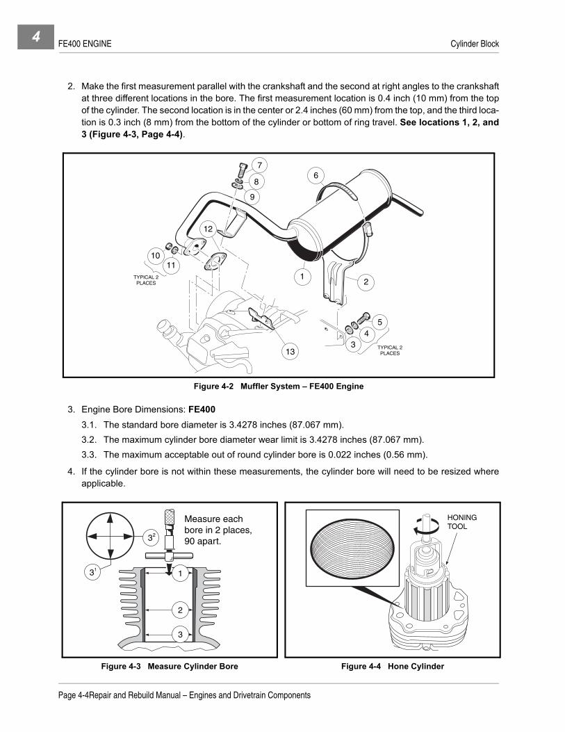
FE400 ENGINE Cylinder Block4
2. Make the first measurement parallel with the crankshaft and the second at right angles to the crankshaftat three different locations in the bore. The first measurement location is 0.4 inch (10 mm) from the topof the cylinder. The second location is in the center or 2.4 inches (60 mm) from the top, and the third loca-tion is 0.3 inch (8 mm) from the bottom of the cylinder or bottom of ring travel. See locations 1, 2, and3 (Figure 4-3, Page 4-4).
3. Engine Bore Dimensions: FE4003.1. The standard bore diameter is 3.4278 inches (87.067 mm).3.2. The maximum cylinder bore diameter wear limit is 3.4278 inches (87.067 mm).3.3. The maximum acceptable out of round cylinder bore is 0.022 inches (0.56 mm).
4. If the cylinder bore is not within these measurements, the cylinder bore will need to be resized whereapplicable.
Figure 4-2 Muffler System – FE400 Engine
Figure 4-3 Measure Cylinder Bore Figure 4-4 Hone Cylinder
67
8
9
12
TYPICAL 2 PLACES
12
1011
13
5
TYPICAL 2 PLACES
34
3 1
3 2
Measure each bore in 2 places, 90 apart.
1
2
3
HONING TOOL
Page 4-4Repair and Rebuild Manual – Engines and Drivetrain Components

FE400 ENGINE Cylinder Block 4
To Resize Bore to Next Oversize
CAUTION
• It is not recommended that the bore size of the FE400 be made larger than standard bore size.
1. The standard bore size is 3.4478 inches (87.574 mm). See Specifications for Resizing Cylinder Boreon page 4-6.
NOTE: The bore diameter can be increased by honing to correct an out of round condition to a total of .022inches (0.56 mm) maximum diameter.
2. Hone the cylinder to the final bore diameter of 3.4698 inches (88.133 mm). See Specifications forResizing Cylinder Bore on page 4-6. See following CAUTION and NOTE.
NOTE: The cylinder wall finish should have a 40° to 60° cross-hatch pattern (Figure 4-4, Page 4-4).
Do not use solvents or gasoline to clean cylinder after honing. Solvents and gasoline allow thegrindings to remain in the honed surface and will not provide a surface suited for ring seating.
3. After honing, clean the cylinder wall thoroughly using soap, warm water and clean rags.
4. Dry the cylinder and coat with engine oil. See following CAUTION.
CAUTION
• The cylinder must be thoroughly cleaned after honing to eliminate all grit.
Crankshaft and Counterbalance Weight
ý WARNING
• Before assembly, make sure all parts are clean.
CAUTION
• The crankshaft and counterbalance weight look the same on the FE350 and FE400 engines,but they are not. Do not mix. The crankshaft and counterbalance weight for each engine aredesigned to be fitted as a set.
NOTE: The crankshaft for the FE400 engine has a different center line dimension from the main journal tothe rod journal than the FE350. They are not interchangable.
The counterbalance weight has different dimensions for the FE400 engine than the FE350. Theyare not interchangable.
When reassembling the crankshaft and the counterbalance weight, apply a light film of engine oilto the crankshaft journals and guide shaft.
Piston and Connecting Rod
NOTE: The piston connecting rod for the FE350 and FE400 engines are the same. But, it’s not recom-mended to mix a rod from one engine with a rod from another engine after either has been used.
The pistons for the FE350 and FE400 are different. The piston for the FE400 is larger in diameterand the rod pin is on a different center line from the top of the piston surface.
Repair and Rebuild Manual – Engines and Drivetrain ComponentsPage 4-5

FE400 ENGINE Engine Installation4
ENGINE INSTALLATION
ý CAUTION
• The FE400 engine is designed to be used on the MC012C-AS00 or MC012C-BS00 transaxle. Donot use it on any other transaxle assembly.
See Engine Installation in the appropriate maintenance and service manual.
SERVICE SPECIFICATIONS
SPECIFICATIONS FOR RESIZING CYLINDER BORE
TORQUE SPECIFICATIONS
ADJUSTMENT AND SETTINGS
ITEM SERVICE LIMIT FE400 ENGINE
Camshaft axial play 0.024 in. (0.06 mm)
Cylinder bore (standard) 3.4278 in. (87.067 mm) inner diameter standard
Cylinder bore (maximum) 3.4278 in. (87.067 mm) inner diameter maximum
ITEM HONING OVERSIZE FE400 LIMITS
Finished honed bore diameter Not applicable 3.4278 in. (87.067 mm))
ITEM SIZE FE350 AND FE400 LIMITS
Cylinder head bolts M8 17.5 ft-lb (24 N·m)
Connecting rod bolts(coat threads with engine oil) M7 16.5 ft-lb (23 N·m)
Flywheel retaining nut M18 100 ft-lb (135 N·m)
Crankcase cover to block bolts M8 22 ft-lb (31 N·m)
Starter/Generator bracket to block bolts M8 16.5 ft-lb (23 N·m)
Oil drain plug M14 16.5 ft-lb (23 N·m)
Fan housing screws M6 90 in-lb (10 N·m)
Fan shroud screws M6 25 in-lb (2.8 N·m)
Bolts marked with “4” (when used with nuts)
M8M6M5
130 in-lb (15 N·m)50 in-lb (5.9 N·m)30 in-lb (3.4 N·m)
ITEM SERVICE LIMIT FE400 ENGINE
Engine RPM 3850 (±30) RPM
Page 4-6Repair and Rebuild Manual – Engines and Drivetrain Components

5
SECTION 5 – MC008C-ES00 AND MC008C-FS00 UNITIZED TRANSAXLESý DANGER
• See General Warning on page 1-1.
ý WARNING
• See General Warning on page 1-1.
GENERAL INFORMATION
The MC008C-ES00 and MC008C-FS00 are heavy-duty, fully-synchronized unitized transaxles. With fully-synchronized internal gearing to change vehicle direction, wear and maintenance requirements on theengine, drive clutch, belt, and driven clutch are greatly reduced. All components rotate in the same direction;therefore, the engine and clutches are not subjected to reversing loads. Power is transferred from the enginethrough the drive clutch, the drive belt, the driven clutch, then through the unitized transaxle to the wheels.
TRANSAXLE MODELS AND IDENTIFICATION
The MC008C-ES00 transaxle has been supplied on all FE290 gasoline engine powered Club Car vehiclessince the beginning of the 1997 model year (Figure 5-1, Page 5-1). The MC008C-FS00 replaced the ES00model in October, 2003. Both operate the same. Most parts and housing are the same. The input shaft andassociated bearings are different between the two models. All parts are identified in their respective illustratedparts list (IPL) manuals. Both models are illustrated here for purposes of service procedures. All illustrated ref-erences will be shown for the MC008C-ES00 except where components are specific to the MC008C-FS00.
Figure 5-1 MC008C-ES00
IDENTIFICATIONDECAL
Repair and Rebuild Manual – Engines and Drivetrain ComponentsPage 5-1

MC008C-ES00 AND MC008C-FS00 UNITIZED TRANSAXLESAxle Shaft5
Tools Required For This Section
AXLE SHAFT
See Axle Shaft and Oil Seal Removal, Section 16, in the appropriate maintenance and service manual.
UNITIZED TRANSAXLE REMOVAL
See Unitized Transaxle Removal, Section 16, in the appropriate maintenance and service manual.
UNITIZED TRANSAXLE DISASSEMBLY
See General Warning on page 1-1.
NOTE: The following information provides instructions for disassembling the unitized transaxle and inter-nal gears.
1. Position the unitized transaxle case on a clean bench surface with the bottom lubrication plug over a pansuitable for draining lubrication oil.
2. Remove both the top and bottom lubrication port plugs and gaskets. Drain and dispose of the oil properly(Figure 5-2, Page 5-3). See following NOTE.
NOTE: The lower plug is used for draining lubricant. When draining lubricant, remove both plugs to allow
the lubricant to drain faster.
Hydraulic floor jack (or chain hoist) 12 to 18 in. straight edge 17 mm socket, 3/8 in. driveJack stands (2) (one ton capacity) Small ball peen hammer (10 oz.) 7/16 in. combination wrenchHydraulic press Plastic or rubber mallet 1/2 in. combination wrenchBench vise Ratchet wrench, 3/8 in. drive 9/16 in. combination wrenchStandard slip joint pliers Torque wrench, 3/8 in. drive 11/16 in. combination wrench (2)External snap ring pliers (.070 in. tip) 3/8 in. Socket, 3/8 in. drive 17 mm combination wrenchExternal snap ring pliers (.047 in. tip) 7/16 in. Socket, 3/8 in. drive Small flat blade screwdriver90° Internal snap ring pliers (.090 in. tip) 10 mm Combination wrench Medium flat blade screwdrivers (2)Feeler gauge 1/2 in. Socket, 3/8 in. drive No. 2 phillips head screwdriver16 in. rolling head prybar 9/16 in. Socket, 3/8 in. drive 1/4 in. nut driverSmall punch or scratch awl 5/8 in. Socket, 3/8 in. drive 5/16 in. nut driver1/4 in. diameter drift or metal rod 12 mm Socket, 3/8 in. drive Small knife or wire snippersBearing puller wedge attachment(CCI P/N 1012812)
Axle seal tool(CCI P/N 1014162)
Governor gear shaft installation tool (CCI P/N 101933101)
Page 5-2Repair and Rebuild Manual – Engines and Drivetrain Components
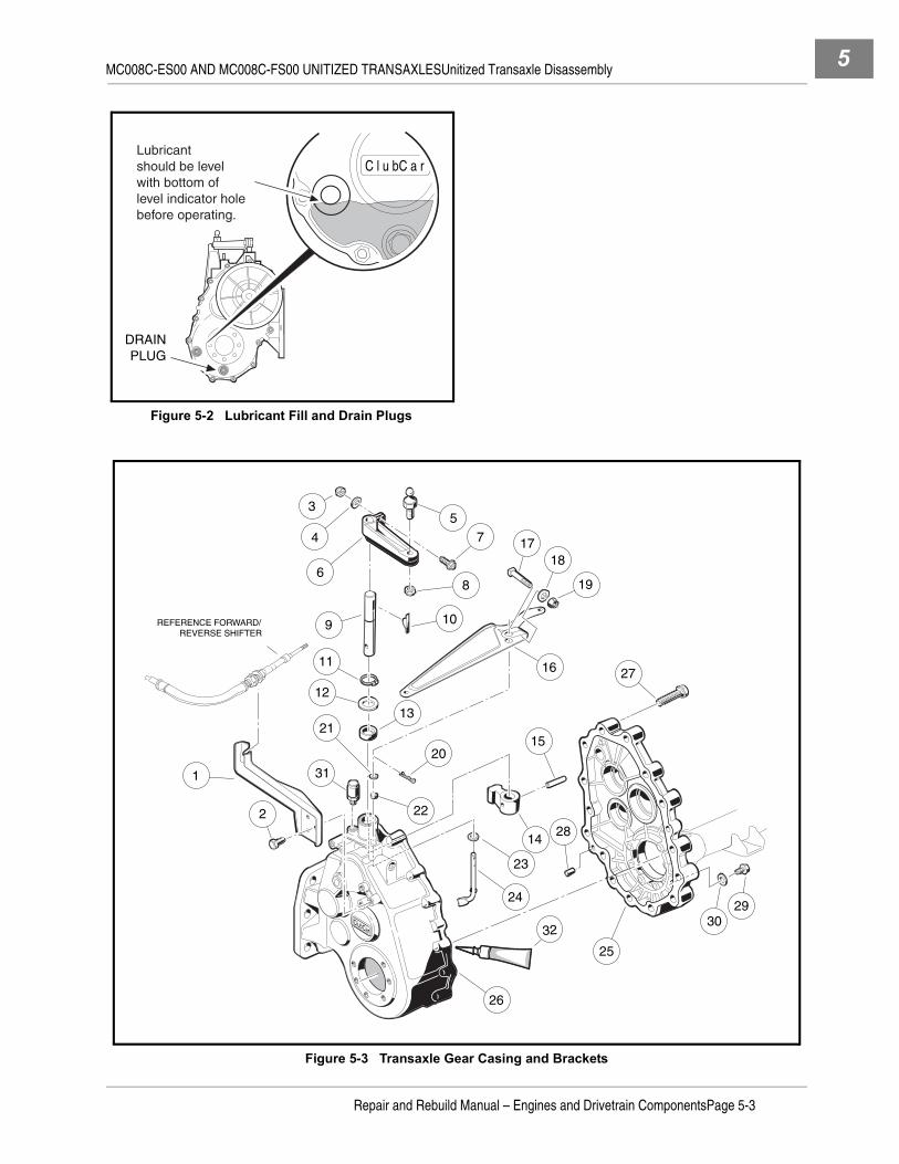
MC008C-ES00 AND MC008C-FS00 UNITIZED TRANSAXLESUnitized Transaxle Disassembly 5
Figure 5-2 Lubricant Fill and Drain Plugs
Figure 5-3 Transaxle Gear Casing and Brackets
DRAINPLUG
C l u b C a rLubricant should be level with bottom of level indicator hole before operating.
3029
ClubCar
3
4
9
6
57
8
10
1718
19
1611
12
1321
22
20
31
14
15
23
24
28
27
25
26
1
2
REFERENCE FORWARD/ REVERSE SHIFTER
32
Repair and Rebuild Manual – Engines and Drivetrain ComponentsPage 5-3

MC008C-ES00 AND MC008C-FS00 UNITIZED TRANSAXLESUnitized Transaxle Disassembly5
3. Remove the fifteen bolts (27) that hold the transaxle housing together (Figure 5-3, Page 5-3).
4. The transaxle is equipped with a slot for prying the housing apart. Use the slot to open the case. Makesure all gear assemblies inside the transaxle stay together in one (either) side of the case. See followingCAUTION.
CAUTION
• To prevent damage to the mating seal surfaces of the case, use care when separating thehalves.
5. Turn the case section containing the gearing on edge (Figure 5-4, Page 5-4). Hold it in this position andgently rock all the gear assemblies to slightly loosen them in their seating. See following CAUTION.
CAUTION
• To prevent damage to the gears, use extreme care when handling them.
6. Remove the differential gear case assembly by gently rocking it while pulling it from the case (Figure 5-5,Page 5-4).
7. Continue to rock and loosen the remaining gear assemblies until the intermediate gear assembly can beremoved. Remove the idler shaft assembly (Figure 5-6, Page 5-5).
Figure 5-4 Loosen Gears Figure 5-5 Remove Differential Gear Case
DIFFERENTIALGEAR CASEASSEMBLY
Page 5-4Repair and Rebuild Manual – Engines and Drivetrain Components
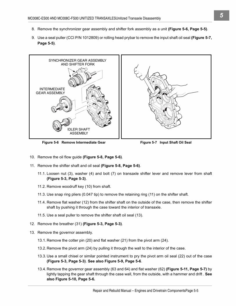
MC008C-ES00 AND MC008C-FS00 UNITIZED TRANSAXLESUnitized Transaxle Disassembly 5
8. Remove the synchronizer gear assembly and shifter fork assembly as a unit (Figure 5-6, Page 5-5).
9. Use a seal puller (CCI P/N 1012809) or rolling head prybar to remove the input shaft oil seal (Figure 5-7,Page 5-5).
10. Remove the oil flow guide (Figure 5-8, Page 5-6).
11. Remove the shifter shaft and oil seal (Figure 5-8, Page 5-6).
11.1. Loosen nut (3), washer (4) and bolt (7) on transaxle shifter lever and remove lever from shaft(Figure 5-3, Page 5-3).
11.2. Remove woodruff key (10) from shaft.
11.3. Use snap ring pliers (0.047 tip) to remove the retaining ring (11) on the shifter shaft.
11.4. Remove flat washer (12) from the shifter shaft on the outside of the case, then remove the shiftershaft by pushing it through the case toward the interior of transaxle.
11.5. Use a seal puller to remove the shifter shaft oil seal (13).
12. Remove the breather (31) (Figure 5-3, Page 5-3).
13. Remove the governor assembly.
13.1. Remove the cotter pin (20) and flat washer (21) from the pivot arm (24).
13.2. Remove the pivot arm (24) by pulling it through the wall to the interior of the case.
13.3. Use a small chisel or similar pointed instrument to pry the pivot arm oil seal (22) out of the case(Figure 5-3, Page 5-3). See also Figure 5-9, Page 5-6.
13.4. Remove the governor gear assembly (63 and 64) and flat washer (62) (Figure 5-11, Page 5-7) bylightly tapping the gear shaft through the case wall, from the outside, with a hammer and drift . Seealso Figure 5-10, Page 5-6.
Figure 5-6 Remove Intermediate Gear Figure 5-7 Input Shaft Oil Seal
SYNCHRONIZER GEAR ASSEMBLYAND SHIFTER FORK
INTERMEDIATEGEAR ASSEMBLY
IDLER SHAFT ASSEMBLY
Repair and Rebuild Manual – Engines and Drivetrain ComponentsPage 5-5

MC008C-ES00 AND MC008C-FS00 UNITIZED TRANSAXLESComponent Disassembly5
COMPONENT DISASSEMBLY
See General Warning on page 1-1.
GOVERNOR GEAR DISASSEMBLY
NOTE: It will be necessary to disassemble the governor gear assembly in order to install it into the tran-saxle case.
Figure 5-8 Oil Flow Guide Figure 5-9 Pivot Arm Oil Seal
Figure 5-10 Remove Governor Gear
SLOT
OIL FLOW GUIDE
SHIFTER SHAFT
TAB
ClubCar
ClubCar
Page 5-6Repair and Rebuild Manual – Engines and Drivetrain Components

MC008C-ES00 AND MC008C-FS00 UNITIZED TRANSAXLESComponent Disassembly 5
Figure 5-11 MC008C-ES00 Unitized Transaxle
ClubCar
REFERENCE DRIVER SIDE
CASE
3738
3940
4142
4445 41
46
33
34
3536
4748
46
5051
4541
52
5339
54
3856
57
5859
6263
64
6665
66
49
5543
43
REFERENCE PASSENGER SIDE
CASE
48
Parts identification for transaxles prior toserial number MC008C3H1264
Repair and Rebuild Manual – Engines and Drivetrain ComponentsPage 5-7

MC008C-ES00 AND MC008C-FS00 UNITIZED TRANSAXLESComponent Disassembly5
Figure 5-12 MC008C-FS00 Unitized Transaxle
ClubCar
REFERENCE DRIVER SIDE
CASE
37
3940
4142
4445 41
46
33
34
3536
4748
46
50
4541
52
5339
3856
57
5859
62
63
64
6665
66
49
5543
43
REFERENCE PASSENGER SIDE
CASE
48
SEALED C3BEARING
SEALEDBEARING
Parts identification for transaxles beginning withserial number MC008C3H1264
67
6869
70
Page 5-8Repair and Rebuild Manual – Engines and Drivetrain Components

MC008C-ES00 AND MC008C-FS00 UNITIZED TRANSAXLESComponent Disassembly 5
1. Secure the governor gear assembly in a vise. Wrap shaft in a cloth to prevent damage (Figure 5-13,Page 5-9).
2. Use two small screwdrivers to pry the gear and flyweight off the shaft.
DIFFERENTIAL GEAR CASE DISASSEMBLY
CAUTION
• Mark parts for identification as they are disassembled. Parts must be assembled in theiroriginal locations and orientations.
1. Remove eight ring gear retaining bolts (80) and remove the ring gear from the assembly (Figure 5-14,Page 5-9).
Figure 5-13 Pry Gear from Shaft
Figure 5-14 Differential Gear Case
ClubCar
7987
86
90
89
85
91
84
82
89
85
88
81
80
79
83
REFERENCEDRIVER SIDECASE
REFERENCEPASSENGER SIDECASE
Repair and Rebuild Manual – Engines and Drivetrain ComponentsPage 5-9
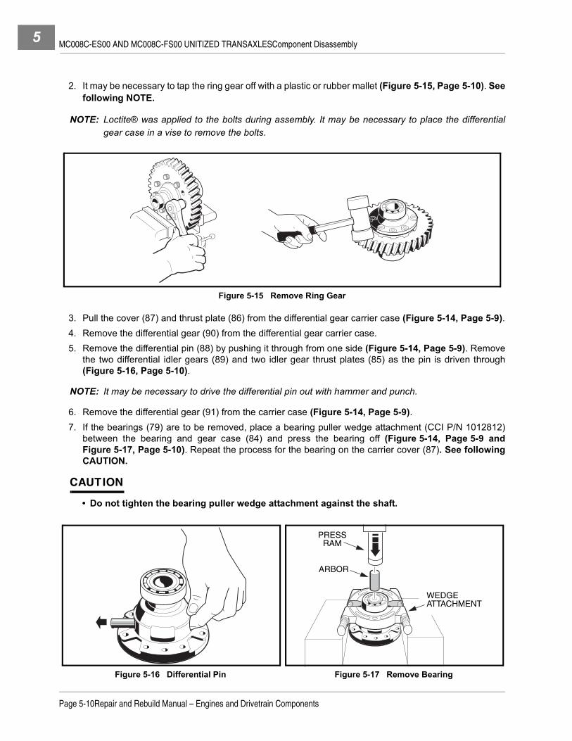
MC008C-ES00 AND MC008C-FS00 UNITIZED TRANSAXLESComponent Disassembly5
2. It may be necessary to tap the ring gear off with a plastic or rubber mallet (Figure 5-15, Page 5-10). Seefollowing NOTE.
NOTE: Loctite® was applied to the bolts during assembly. It may be necessary to place the differentialgear case in a vise to remove the bolts.
3. Pull the cover (87) and thrust plate (86) from the differential gear carrier case (Figure 5-14, Page 5-9).4. Remove the differential gear (90) from the differential gear carrier case.5. Remove the differential pin (88) by pushing it through from one side (Figure 5-14, Page 5-9). Remove
the two differential idler gears (89) and two idler gear thrust plates (85) as the pin is driven through(Figure 5-16, Page 5-10).
NOTE: It may be necessary to drive the differential pin out with hammer and punch.
6. Remove the differential gear (91) from the carrier case (Figure 5-14, Page 5-9).7. If the bearings (79) are to be removed, place a bearing puller wedge attachment (CCI P/N 1012812)
between the bearing and gear case (84) and press the bearing off (Figure 5-14, Page 5-9 andFigure 5-17, Page 5-10). Repeat the process for the bearing on the carrier cover (87). See followingCAUTION.
CAUTION
• Do not tighten the bearing puller wedge attachment against the shaft.
Figure 5-15 Remove Ring Gear
Figure 5-16 Differential Pin Figure 5-17 Remove Bearing
ARBOR
PRESSRAM
WEDGEATTACHMENT
Page 5-10Repair and Rebuild Manual – Engines and Drivetrain Components

MC008C-ES00 AND MC008C-FS00 UNITIZED TRANSAXLESComponent Disassembly 5
SHIFTER FORK DISASSEMBLY
1. Push the shift rod (33) out of the shifter fork (34) (Figure 5-11, Page 5-7).
2. Shake the shifter fork to remove the spring (35) and ball (36).
SYNCHRONIZER GEAR DISASSEMBLY
CAUTION
• Mark parts for identification as they are disassembled. Parts must be assembled in theiroriginal locations and orientations.
• Do not tighten the bearing puller wedge attachment against the shaft. This could damage theshaft.
1. MC008C-ES00:
1.1. Place a bearing puller wedge attachment (CCI P/N 1012812) between the bearing (38) and spur(governor drive) gear (40) (Figure 5-11, Page 5-7), then press the bearing off the input shaft (51)(Figure 5-18, Page 5-12). See preceding CAUTION.
2. MC008C-FS00:
2.1. Place a bearing puller wedge attachment (CCI P/N 1012812) between the sealed bearing (67) andspur (governor drive) gear (40) (Figure 5-12, Page 5-8), then press the bearing off the input shaft(70) (Figure 5-18, Page 5-12). See preceding CAUTION.
3. Pull the spring washer (39), spur gear (40), dowel pin (50), thrust plate (41), input gear assembly (42),large needle bearing (43), small needle bearing (44), synchronizer ring (45), and thrust plate (41) fromthe input shaft (Figure 5-11, Page 5-7 or Figure 5-12, Page 5-8).
4. MC008C-ES00:
4.1. Place a bearing puller wedge attachment (CCI P/N 1012812) between the bearing (54) and inputgear assembly (52) (Figure 5-11, Page 5-7), then press the bearing off the input shaft (51)(Figure 5-11, Page 5-7). See following CAUTION.
5. MC008C-FS00:
5.1. Remove the external snap ring (69) from the input shaft (70) (Figure 5-12, Page 5-8).
5.2. Place a bearing puller wedge attachment (CCI P/N 1012812) between the sealed C3 bearing (68)and input gear assembly (52) (Figure 5-12, Page 5-8), then press the bearing off the input shaft(70) (Figure 5-19, Page 5-12). See following CAUTION.
CAUTION
• Do not tighten the bearing puller wedge attachment against the shaft.
6. Pull the spring washer (39), thrust washer (53), input gear assembly (52), two needle bearings (43),thrust plate (41), and synchronizer ring (45) from the input shaft (Figure 5-11, Page 5-7 or Figure 5-12,Page 5-8).
Repair and Rebuild Manual – Engines and Drivetrain ComponentsPage 5-11

MC008C-ES00 AND MC008C-FS00 UNITIZED TRANSAXLESComponent Disassembly5
7. Use a small flat-blade screwdriver to remove two synchronizer springs (snap rings) (46), then slide thesynchronizer clutch hub (49) from the input shaft (51). See following NOTE.
NOTE: There are three synchronizer inserts (48) set into slots in the synchronizer sleeve (47)(Figure 5-11, Page 5-7). These may fall free when the synchronizer clutch hub (49) is removed.Do not lose these inserts.
8. Remove the three synchronizer inserts (48) from the synchronizer sleeve (Figure 5-11, Page 5-7).
9. Press the synchronizer sleeve (47) from the input shaft.
INTERMEDIATE GEAR DISASSEMBLY
1. Place bearing puller wedge attachment (CCI P/N 1012812) between bearing (38) and shaft/gear (56)(Figure 5-11, Page 5-7), then press bearing off shaft (Figure 5-20, Page 5-13). See following CAU-TION.
CAUTION
• Do not tighten the bearing puller wedge attachment against the shaft. This could damage theshaft.
2. Place the bearing puller wedge attachment under the bearing (59) and press the bearing from the shaft(Figure 5-11, Page 5-7). See following CAUTION.
3. Press the gear (58) from the shaft (56), then remove the key (57) .
Figure 5-18 Remove Bearing Figure 5-19 Remove Bearing
ARBOR
PRESSRAM
WEDGEATTACHMENT
PRESS RAM
BEARING PULLERWEDGE ATTACHMENT
Page 5-12Repair and Rebuild Manual – Engines and Drivetrain Components
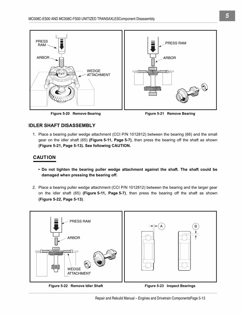
MC008C-ES00 AND MC008C-FS00 UNITIZED TRANSAXLESComponent Disassembly 5
IDLER SHAFT DISASSEMBLY
1. Place a bearing puller wedge attachment (CCI P/N 1012812) between the bearing (66) and the smallgear on the idler shaft (65) (Figure 5-11, Page 5-7), then press the bearing off the shaft as shown(Figure 5-21, Page 5-13). See following CAUTION.
CAUTION
• Do not tighten the bearing puller wedge attachment against the shaft. The shaft could bedamaged when pressing the bearing off.
2. Place a bearing puller wedge attachment (CCI P/N 1012812) between the bearing and the larger gearon the idler shaft (65) (Figure 5-11, Page 5-7), then press the bearing off the shaft as shown(Figure 5-22, Page 5-13).
Figure 5-20 Remove Bearing Figure 5-21 Remove Bearing
Figure 5-22 Remove Idler Shaft Figure 5-23 Inspect Bearings
ARBOR
PRESSRAM
WEDGEATTACHMENT
ARBOR
PRESS RAM
ARBOR
PRESS RAM
WEDGEATTACHMENT
A B
Repair and Rebuild Manual – Engines and Drivetrain ComponentsPage 5-13

MC008C-ES00 AND MC008C-FS00 UNITIZED TRANSAXLESUnitized Transaxle Component Inspection5
UNITIZED TRANSAXLE COMPONENT INSPECTION
See General Warning on page 1-1.1. Clean all of the component parts of the transaxle in a high flash-point solvent and dry them. Inspect all
components for excessive wear or damage.2. Inspect all bearings by spinning them by hand. Check the bearings for excessive axial (A) and radial (B)
play (Figure 5-23, Page 5-13). Replace bearings if they do not spin smoothly, if they are noisy, or if theyhave excessive play. Replace bearings if they are rusted, worn, cracked, pitted, or discolored.
3. Gears should be inspected for tooth surface damage or fractures.4. Synchronizer ring teeth should be inspected for severe wear, fractures, or other damage.5. Using a feeler gauge, measure the distance X at several points around the assembly. The synchro ring
should be replaced when X is 0.02 inch (0.5 mm) or less (Figure 5-24, Page 5-14).
COMPONENT ASSEMBLY
See General Warning on page 1-1.
IDLER SHAFT ASSEMBLY1. Press a new bearing (66) (Figure 5-11, Page 5-7) onto each end of the idler shaft (Figure 5-25,
Page 5-14). See following CAUTION.
CAUTION
• Apply pressure against the inner race of the bearing only. Applying pressure anywhere elsewill damage the bearing.
INTERMEDIATE GEAR ASSEMBLY1. If the gear (58) was removed from the shaft, install the key (57) into the slot and then position the gear
on the shaft with keyway properly aligned with key. Press gear into place on the key (Figure 5-11,Page 5-7).
2. Press the bearing (59) onto the end of the shaft next to the large gear that was installed in step 1. Seepreceding CAUTION.
3. Press a new bearing (38) onto the other end of the shaft.
Figure 5-24 Synchronizer Ring Figure 5-25 Idler Shaft
X Press bearingonto idler shaft.
Turn idler shaft over and press
bearing onother end.
B
A
Page 5-14Repair and Rebuild Manual – Engines and Drivetrain Components

MC008C-ES00 AND MC008C-FS00 UNITIZED TRANSAXLESComponent Assembly 5
SYNCHRONIZER GEAR ASSEMBLY1. MC008C-ES00:
1.1. Press the synchronizer sleeve (47) onto the splines of the input shaft (51) (Figure 5-11, Page 5-7).No particular orientation of the sleeve is necessary, but toward the short end of the shaft, themachined circular face surrounding the ends of the internal splines in the sleeve must be flush withthe machined lip of the shaft at the ends of the shaft splines (Figure 5-26, Page 5-15).
1.2. Install the synchronizer springs (46) (Figure 5-11, Page 5-7) in the sleeve (Figure 5-27,Page 5-15). See following NOTE.
NOTE: Make sure the ends of the springs are positioned between the synchronizer insert slots(Figure 5-27, Page 5-15).
1.3. Install the three synchronizer inserts (48) into the slots in the sleeve (Figure 5-11, Page 5-7). Makesure the notched surfaces of the inserts are facing outward (Figure 5-28, Page 5-17).
1.4. Install the synchronizer clutch hub (49) (Figure 5-11, Page 5-7) onto the synchronizer sleeve.Make sure the chamfered end of the hub is oriented toward the long end of the input shaft(Figure 5-29, Page 5-17).
1.5. On the long end of the shaft, install the synchronizer ring (45) (Figure 5-11, Page 5-7) with thesmooth collar of the ring towards the clutch hub. Make sure the three notches in the collar mate withthe synchronizer inserts in the synchronizer sleeve (Figure 5-30, Page 5-18).
1.6. Install a thrust washer (41) and two bearings (43) (Figure 5-11, Page 5-7).1.7. Install the input gear assembly (52) with the smooth collar toward the synchronizer ring. The input
gear should seat in the synchronizer ring.
1.8. Install the thrust washer (53), then the spring washer (39). The spring washer should be orientedwith the raised center toward the end of the shaft.
1.9. Press a new bearing (38) onto the shaft (51) until it seats. Make sure the input gear turns freely(Figure 5-11, Page 5-7). See following CAUTION.
Figure 5-26 Synchronizer Gear Assembly Figure 5-27 Synchronizer Springs
PRESSRAM
SYNCHRONIZERSLEEVE
INPUTSHAFT
MACHINEDFACE OF
SYNCHRO.SLEEVE
TOP OF SPLINE
Top of spline pressed level with machined
face.
Install springson top and bottomof synchronizersleeve as shown.
Endspositioned
betweeninsert slots.
FRONT VIEW
SYNCHRONIZER INSERT SLOTS
Repair and Rebuild Manual – Engines and Drivetrain ComponentsPage 5-15

MC008C-ES00 AND MC008C-FS00 UNITIZED TRANSAXLESComponent Assembly5
CAUTION
• Apply pressure against the inner race of the bearing only. Applying pressure anywhere elsewill damage the bearing.
1.10. Install remaining thrust washer (41) and the synchronizer ring (45) onto the other end of the inputshaft. The smooth collar of the synchronizer ring should be oriented toward the clutch hub, and thenotches in it should mate with the synchronizer inserts.
1.11. Install the narrow bearing (44), wide bearing (43), and input gear (42) onto the shaft. The smoothcollar of the input gear should be oriented toward the synchronizer ring. The gear should seat insidethe ring.
1.12. Install thrust plate (41) onto the shaft and the dowel pin (50) into the shaft.1.13. Install the spur (governor drive) gear (40) onto the shaft with either side down. Mate the notch in the
gear with the dowel pin. 1.14. Install the spring washer (39) onto shaft with the raised center toward the end of the shaft.1.15. Press a new bearing (38) onto the end of the shaft (51) until it seats. Make sure the input gears turn
freely (Figure 5-11, Page 5-7). See following CAUTION.1.16. Press a new bearing (54) onto the shaft (51) until it seats. Make sure the input gear turns freely
(Figure 5-11, Page 5-7). See following CAUTION.
CAUTION
• Apply pressure against the inner race of the bearing only. Applying pressure anywhere elsewill damage the bearing.
2. MC008C-FS00:2.1. Press the synchronizer sleeve (47) onto the splines of the input shaft (70) (Figure 5-12, Page 5-8).
No particular orientation of the sleeve is necessary, but toward the short end of the shaft, themachined circular face surrounding the ends of the internal splines in the sleeve must be flush withthe machined lip of the shaft at the ends of the shaft splines (Figure 5-26, Page 5-15).
2.2. Install the synchronizer springs (46) (Figure 5-12, Page 5-8) in the sleeve (Figure 5-27,Page 5-15). See following NOTE.
NOTE: Make sure the ends of the springs are positioned between the synchronizer insert slots(Figure 5-27, Page 5-15).
2.3. Install the three synchronizer inserts (48) into the slots in the sleeve (Figure 5-12, Page 5-8). Makesure the notched surfaces of the inserts are facing outward (Figure 5-28, Page 5-17).
2.4. Install the synchronizer clutch hub (49) (Figure 5-12, Page 5-8) onto the synchronizer sleeve.Make sure the chamfered end of the hub is oriented toward the long end of the input shaft(Figure 5-29, Page 5-17).
2.5. On the long end of the shaft, install the synchronizer ring (45) (Figure 5-12, Page 5-8) with thesmooth collar of the ring towards the clutch hub. Make sure the three notches in the collar mate withthe synchronizer inserts in the synchronizer sleeve (Figure 5-30, Page 5-18).
2.6. Install a thrust washer (41) and two bearings (43) (Figure 5-12, Page 5-8).2.7. Install the input gear assembly (52) with the smooth collar toward the synchronizer ring. The input
gear should seat in the synchronizer ring.2.8. Install the thrust washer (53), then the spring washer (39). The spring washer should be oriented
with the raised center toward the end of the shaft.
Page 5-16Repair and Rebuild Manual – Engines and Drivetrain Components

MC008C-ES00 AND MC008C-FS00 UNITIZED TRANSAXLESComponent Assembly 5
2.9. Press a new sealed C3 bearing (68) onto the shaft (70) until it seats. Make sure the input gear turnsfreely (Figure 5-12, Page 5-8). See following CAUTION.
CAUTION
• Apply pressure against the inner race of the bearing only. Applying pressure anywhere elsewill damage the bearing.
2.10. Install the external snap ring (69) on the shaft (70).2.11. Install remaining thrust washer (41) and the synchronizer ring (45) onto the other end of the input
shaft. The smooth collar of the synchronizer ring should be oriented toward the clutch hub, and thenotches in it should mate with the synchronizer inserts.
2.12. Install the narrow bearing (44), wide bearing (43), and input gear (42) onto the shaft. The smoothcollar of the input gear should be oriented toward the synchronizer ring. The gear should seat insidethe ring.
2.13. Install thrust plate (41) onto the shaft and the dowel pin (50) into the shaft.2.14. Install the spur (governor drive) gear (40) onto the shaft with either side down. Mate the notch in the
gear with the dowel pin. 2.15. Install the spring washer (39) onto shaft with the raised center toward the end of the shaft.2.16. Press a new sealed bearing (67) onto the shaft (70) until it seats. Make sure the input gear turns
freely (Figure 5-12, Page 5-8). See following CAUTION.
CAUTION
• Apply pressure against the inner race of the bearing only. Applying pressure anywhere elsewill damage the bearing.
Figure 5-28 Synchronizer Inserts Figure 5-29 Synchronizer Clutch Hub
Synchronizer inserts overlap springs.
TOP VIEW
Notchedsurfacesof synchro.inserts faceout. SPRINGS TOP AND BOTTOM
SIDE VIEW
CHAMFERED ON END OF CLUTCH HUB
LONG END OF SHAFT
SYNCHRONIZERSLEEVE
SYNCHRONIZERCLUTCH HUB
Repair and Rebuild Manual – Engines and Drivetrain ComponentsPage 5-17

MC008C-ES00 AND MC008C-FS00 UNITIZED TRANSAXLESComponent Assembly5
SHIFTER FORK ASSEMBLY1. Install the spring (35) and ball (36) into the shifter fork (34) (Figure 5-31, Page 5-18).
2. Use a No. 1 tip phillips screwdriver to press the ball and spring while inserting shift rod (33) into the shifterfork (34) (Figure 5-32, Page 5-18). Remove screwdriver when the shift rod is inserted far enough for itto depress the ball and spring, then continue inserting rod until ball is positioned in the middle groove onthe rod.
Figure 5-30 Synchronizer Ring
Figure 5-31 Align Spring, Ball and Insert Figure 5-32 Insert Shift Rod Past Ball
SYNCHRONIZERRING
SYNCHRONIZERCLUTCH HUB
3334
34
35
35
36
36
3334
34
3536
Page 5-18Repair and Rebuild Manual – Engines and Drivetrain Components
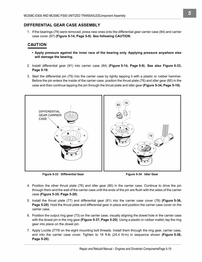
MC008C-ES00 AND MC008C-FS00 UNITIZED TRANSAXLESComponent Assembly 5
DIFFERENTIAL GEAR CASE ASSEMBLY1. If the bearings (79) were removed, press new ones onto the differential gear carrier case (84) and carrier
case cover (87) (Figure 5-14, Page 5-9). See following CAUTION.
CAUTION
• Apply pressure against the inner race of the bearing only. Applying pressure anywhere elsewill damage the bearing.
2. Install differential gear (91) into carrier case (84) (Figure 5-14, Page 5-9). See also Figure 5-33,Page 5-19.
3. Start the differential pin (79) into the carrier case by lightly tapping it with a plastic or rubber hammer.Before the pin enters the inside of the carrier case, position the thrust plate (76) and idler gear (80) in thecase and then continue tapping the pin through the thrust plate and idler gear (Figure 5-34, Page 5-19).
4. Position the other thrust plate (76) and idler gear (80) in the carrier case. Continue to drive the pinthrough them and the wall of the carrier case until the ends of the pin are flush with the sides of the carriercase (Figure 5-35, Page 5-20).
5. Install the thrust plate (77) and differential gear (81) into the carrier case cover (78) (Figure 5-36,Page 5-20). Hold the thrust plate and differential gear in place and position the carrier case cover on thecarrier case.
6. Position the output ring gear (73) on the carrier case, visually aligning the dowel hole in the carrier casewith the dowel pin in the ring gear (Figure 5-37, Page 5-20). Using a plastic or rubber mallet, tap the ringgear into place on the dowel pin.
7. Apply Loctite 277® on the eight mounting bolt threads. Install them through the ring gear, carrier case,and into the carrier case cover. Tighten to 18 ft-lb (24.4 N·m) in sequence shown (Figure 5-38,Page 5-20).
Figure 5-33 Differential Gear Figure 5-34 Idler Gear
DIFFERENTIALGEAR CARRIERCASE
8076
79
Repair and Rebuild Manual – Engines and Drivetrain ComponentsPage 5-19

MC008C-ES00 AND MC008C-FS00 UNITIZED TRANSAXLESComponent Assembly5
Figure 5-35 Second Idler Gear Figure 5-36 Carrier Case
Figure 5-37 Ring Gear Figure 5-38 Retaining Bolts
7680
79
81
78
77
73
DOWEL PIN
DOWELPIN
HOLE
LOCTITE 277
1
2
3 4
5
6
7
8
Page 5-20Repair and Rebuild Manual – Engines and Drivetrain Components

MC008C-ES00 AND MC008C-FS00 UNITIZED TRANSAXLESUnitized Transaxle Assembly 5
GOVERNOR GEAR ASSEMBLY
The governor gear is not assembled before installing it in the unitized transaxle case. The governor gear shaftis installed into the case and then the rest of the governor gear assembly is installed on the shaft. Proceedwith unitized transaxle assembly.
UNITIZED TRANSAXLE ASSEMBLY
See General Warning on page 1-1.
NOTE: Although the following drawings show the transaxle being assembled in an upright position, layingthe transaxle on its left (driver) side will simplify the assembly process.
1. Make sure both parts of the case are clean and free of any contaminants. Make sure the machined mat-ing surfaces are free of residue and are not scratched or damaged in any way.
2. Put a light coating of clean transmission oil on the outside edge of the seal to make installation easier.Press two new oil seals (13 and 22) (Figure 5-3, Page 5-3) into the left (driver) side case. Use an oil sealinstallation tool (CCI P/N 1014160) to install a new oil seal (55) (Figure 5-11, Page 5-7) into the right(passenger side) case. See also Figure 5-39, Page 5-21.
3. Position the governor gear shaft installation tool (CCI P/N 101933101) over the shaft bore in the insideof the left (driver) side case and insert the governor gear shaft into the tool, long end (from the groove)first (Figure 5-40, Page 5-21). Make sure the shaft is started into the bore and then, using a plastic orrubber hammer, carefully tap the governor gear shaft into the bore until the end being tapped is flush withthe end of the tool. Remove installation tool.
Figure 5-39 Install Seals Figure 5-40 Governor Gear Shaft
ClubCar
SHAFT
TOOL
Repair and Rebuild Manual – Engines and Drivetrain ComponentsPage 5-21

MC008C-ES00 AND MC008C-FS00 UNITIZED TRANSAXLESUnitized Transaxle Assembly5
4. Install the washer, governor gear, and sleeve together onto the governor shaft (Figure 5-41, Page 5-22).Make sure the sleeve is properly positioned within the flyweight brackets of the gear, then push them ontothe shaft until the gear snaps into the groove on the shaft (Figure 5-42, Page 5-22).
5. Position the interior washer on the pivot arm, then install the pivot arm and washer into the left (driverside) case (Figure 5-43, Page 5-22). Install the exterior washer and cotter pin on the pivot arm outsidethe case. Bend the legs of the cotter pin.
6. Install the shifter shaft into the left (driver side) case (Figure 5-44, Page 5-22). Install the washer and useexternal snap ring pliers (0.070 tip) to install retaining ring on the shifter shaft outside of the case. Makesure the retaining ring is in the groove of the shaft.
Figure 5-41 Position Governor Gear Figure 5-42 Install Governor Gear
Figure 5-43 Pivot Arm Figure 5-44 Insert Shifter Shaft
SLEEVE
GOVERNORGEARWASHER
INSIDE VIEW OF LEFT SIDE CASING
EXTERIOR WASHER
COTTER PIN
INTERIOR WASHER
GOVERNOR ARM
SHIFTER SHAFT
RETAININGRINGWASHER
Page 5-22Repair and Rebuild Manual – Engines and Drivetrain Components

MC008C-ES00 AND MC008C-FS00 UNITIZED TRANSAXLESUnitized Transaxle Assembly 5
7. Install the gear assemblies into the left (driver side) case.
7.1. Stand the left side case on the mounting plate, then install the differential gear case assembly(Figure 5-45, Page 5-23). Do not seat the assembly in the bore, instead insert it far enough that itwill not fall out.
7.2. Install the idler gear assembly into case. Do not seat the assembly in the bore, instead insert it farenough that it will not fall out. No gears mesh at this time (Figure 5-46, Page 5-23).
7.3. Install the oil guide with the baffle toward the case wall (Figure 5-47, Page 5-24). Make sure thetwo tabs on the guide are positioned in the slots in the case.
7.4. Position the shifter fork assembly on the synchronizer gear assembly, then install them together,bearing end first, into the bore containing the oil guide (Figure 5-48, Page 5-24). Do not seat theassembly, instead make sure the spur gear (40) is meshed with the governor gear (63)(Figure 5-11, Page 5-7), and that the shifter lever (14) (Figure 5-3, Page 5-3) is positioned in thebracket on the shifter fork. See also Figure 5-49, Page 5-24.
7.5. Install the intermediate gear assembly into the case (Figure 5-50, Page 5-24). Do not seat theassembly into the bore, instead make sure the output ring gear meshes with the input drive gear(52) on the synchronizer gear assembly and with the small gear on the idler shaft (65) (Figure 5-11,Page 5-7).
Figure 5-45 Differential Gear Assembly Figure 5-46 Idler Gear Assembly
DIFFERENTIALGEAR ASSEMBLY
IDLER GEAR ASSEMBLY
Repair and Rebuild Manual – Engines and Drivetrain ComponentsPage 5-23

MC008C-ES00 AND MC008C-FS00 UNITIZED TRANSAXLESUnitized Transaxle Assembly5
Unitized Transaxle Assembly, Continued:
Figure 5-47 Oil Guide Figure 5-48 Synchronizer Ring Gear
Figure 5-49 Gear Alignment Figure 5-50 Gear Alignment
SLOTTAB
SHIFTER FORK
Cutaway view of shifter fork and synchronizer gear assembly beinginserted as a unit into casing.
As you insert the synchronizer gearassembly (complete with shifter fork)into the casing, several gearsmust mesh together.
Large idler gear and synchronizergear mesh.
Spur gear andgovernor gearmesh.
Shifter arm and theshifter fork slottedarm also mesh.
SHIFTERFORK
The small gear on theintermediate gearassembly meshes with the differential ring gear.
DIFFERENTIALRING GEAR
SYNCHRONIZERINPUT DRIVE GEAR
SMALL IDLER GEAR
Several gears meshas you insert theintermediate gearassembly.
(These three gears mesh.)
LARGEINTERMEDIATEGEAR
Page 5-24Repair and Rebuild Manual – Engines and Drivetrain Components
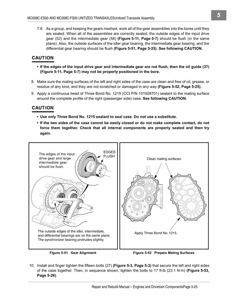
MC008C-ES00 AND MC008C-FS00 UNITIZED TRANSAXLESUnitized Transaxle Assembly 5
7.6. As a group, and keeping the gears meshed, work all of the gear assemblies into the bores until theyare seated. When all of the assemblies are correctly seated, the outside edges of the input drivegear (52) and the intermediate gear (58) (Figure 5-11, Page 5-7) should be flush (in the sameplane). Also, the outside surfaces of the idler gear bearing, the intermediate gear bearing, and thedifferential gear bearing should be flush (Figure 5-51, Page 5-25). See following CAUTION.
CAUTION
• If the edges of the input drive gear and intermediate gear are not flush, then the oil guide (37)(Figure 5-11, Page 5-7) may not be properly positioned in the bore.
8. Make sure the mating surfaces of the left and right sides of the case are clean and free of oil, grease, orresidue of any kind, and they are not scratched or damaged in any way (Figure 5-52, Page 5-25).
9. Apply a continuous bead of Three Bond No. 1215 (CCI P/N 101928701) sealant to the mating surfacearound the complete profile of the right (passenger side) case. See following CAUTION.
CAUTION
• Use only Three Bond No. 1215 sealant to seal case. Do not use a substitute.• If the two sides of the case cannot be easily closed or do not make complete contact, do not
force them together. Check that all internal components are properly seated and then tryagain.
10. Install and finger tighten the fifteen bolts (27) (Figure 5-3, Page 5-3) that secure the left and right sidesof the case together. Then, in sequence shown, tighten the bolts to 17 ft-lb (23.1 N·m) (Figure 5-53,Page 5-26).
Figure 5-51 Gear Alignment Figure 5-52 Prepare Mating Surfaces
The outside edges of the idler, intermediate,and differential bearings are on the same plane.The synchronizer bearing protrudes slightly.
The edges of the inputdrive gear and largeintermediate gearshould be flush.
EDGESFLUSH
Clean mating surfaces.
Apply Three Bond No. 1215.
Repair and Rebuild Manual – Engines and Drivetrain ComponentsPage 5-25

MC008C-ES00 AND MC008C-FS00 UNITIZED TRANSAXLESAxle Tubes5
AXLE TUBES
See Axle Tube Installation, Section 16, in the appropriate maintenance and service manual.
UNITIZED TRANSAXLE INSTALLATION
See Unitized Transaxle Installation, Section 16, in the appropriate maintenance and service manual.
LUBRICATION
See Lubrication, Section 16, in the appropriate maintenance and service manual.
Figure 5-53 Casing Torque Sequence
13
5
6
7
8
9
11
13
14
15
42 10
12
Page 5-26Repair and Rebuild Manual – Engines and Drivetrain Components

6
SECTION 6 – MC010C-BS00 UNITIZED TRANSAXLE WITH DIFFERENTIAL LOCKý DANGER
• See General Warning on page 1-1.
ý WARNING
• See General Warning on page 1-1.
GENERAL INFORMATION
The MC010C-BS00 is a heavy-duty, fully-synchronized unitized transaxle with differential lock. With fully-syn-chronized internal gearing to change vehicle direction, wear and maintenance requirements on the engine,drive clutch, belt, and driven clutch are greatly reduced. All components rotate in the same direction; there-fore, the engine and clutches are not subjected to reversing loads. Power is transferred from the enginethrough the drive clutch, the drive belt, the driven clutch, then through the unitized transaxle to the wheels.
TRANSAXLE MODELS AND IDENTIFICATION
The MC010C-BS00 transaxles have been supplied on models of Turf 272, Carryall 272, and XRT 1200 vehi-cles coupled with one of the FE350 engines. It was replaced with the MC012C-AS00 transaxle. Both operatethe same internally, but utilize a few, slightly different gear components and have two different styles of axleand wheel hub designs. All parts are identified in their respective illustrated parts list (IPL) manuals.
The MC010C-BS00 transaxle is designed with the wheel hub permanently attached to the outside end of eachaxle shaft (Figure 6-1, Page 6-1). The MC012C-AS00 transaxle is designed with a removable wheel boltflange that attaches to the end of the axle shaft using a splined coupling configuration (Figure 6-2, Page 6-1).Both transaxles have different physical attachment provisions and dimensional differences and therefore arenot interchangeable. Further, the MC010C-BS00 transaxle is not designed to handle the FE400 engine.
Figure 6-1 MC010C-BS00 Figure 6-2 MC012C-AS00
IDENTIFICATIONDECAL
RUBBER DUST CAP
IDENTIFICATIONDECAL
Repair and Rebuild Manual – Engines and Drivetrain ComponentsPage 6-1

MC010C-BS00 UNITIZED TRANSAXLE WITH DIFFERENTIAL LOCKAxle Shaft6
Tools Required For This Section
AXLE SHAFT
See Axle Shaft and Oil Seal Removal, Section 16, in the appropriate maintenance and service manual.
UNITIZED TRANSAXLE REMOVAL
See Unitized Transaxle Removal, Section 16, in the appropriate maintenance and service manual.
UNITIZED TRANSAXLE DISASSEMBLY
See General Warning on page 1-1.
NOTE: The following provides instructions for disassembling the unitized transaxle; however, the tran-saxle case can be separated and gears accessed without removing the axles or axle tubes fromthe case.
1. Position the unitized transaxle case on a clean bench surface with the bottom lubrication plug over a pansuitable for draining lubrication oil.
2. Remove both the top and bottom lubrication port plugs and gaskets. Drain and dispose of the oil properly(Figure 6-3, Page 6-3).
NOTE: The lower plug is used for draining lubricant. When draining lubricant, remove both plugs to allowthe lubricant to drain faster.
Hydraulic floor jack (or chain hoist) 12 to 18 in. straight edge 17 mm socket, 3/8-in. driveJack stands (2) (one-ton capacity) Small ball peen hammer (10 oz.) 7/16-in. combination wrenchHydraulic press Plastic or rubber mallet 1/2-in. combination wrenchBench vise Ratchet wrench, 3/8-in. drive 9/16-in. combination wrenchStandard slip joint pliers Torque wrench, 3/8-in. drive 11/16-in. combination wrench (2)External snap ring pliers (.070 in. tip) 3/8-in. Socket, 3/8-in. drive 17 mm combination wrenchExternal snap ring pliers (.047 in. tip) 7/16-in. Socket, 3/8-in. drive Small flat blade screwdriver90° Internal snap ring pliers (.090 in. tip) 10 mm Combination wrench Medium flat blade screwdrivers (2)Feeler gauge 1/2-in. Socket, 3/8-in. drive No. 2 phillips head screwdriver16 in. rolling head prybar 9/16-in. Socket, 3/8-in. drive 1/4-in. nut driverSmall punch or scratch awl 5/8-in. Socket, 3/8-in. drive 5/16-in. nut driver1/4-in. diameter drift or metal rod 12 mm Socket, 3/8-in. drive Small knife or wire snippersBearing puller wedge attachment(CCI P/N 1012812)
Axle seal tool(CCI P/N 1014162)
Governor gear shaft installation tool (CCI P/N 101933101)
Page 6-2Repair and Rebuild Manual – Engines and Drivetrain Components

MC010C-BS00 UNITIZED TRANSAXLE WITH DIFFERENTIAL LOCKUnitized Transaxle Disassembly 6
3. Remove the differential lock housing (94) from the transaxle case (Figure 6-4, Page 6-3).
4. Remove the four bolts (35) and remove the guard (34) (Figure 6-5, Page 6-4).
5. Remove the fifteen bolts (28) that hold the transaxle housing together (Figure 6-5, Page 6-4).
6. The transaxle is equipped with a slot for prying the housing apart. Use the slot to open the case. Pull thehousing apart, making sure all gear assemblies inside the transaxle stay together in one (either) side ofthe case. See following CAUTION.
CAUTION
• To prevent damage to the mating seal surfaces of the case, use care when separating thehalves.
Figure 6-3 Lubricant Level
Figure 6-4 Differential Gear Case
DRAINPLUG
C l u b C a r
Lubricant should be level with bottom of level indicator hole before operating.
ClubCar
29
104
98
100
10296
97
103
9594
99
101
DRIVER SIDE CASE SHOWN FOR REFERENCE
Repair and Rebuild Manual – Engines and Drivetrain ComponentsPage 6-3

MC010C-BS00 UNITIZED TRANSAXLE WITH DIFFERENTIAL LOCKUnitized Transaxle Disassembly6
7. Turn the case section containing the gearing on edge (Figure 6-6, Page 6-5). While holding it in thisposition, gently rock all the gear assemblies to slightly loosen them in their seating. See following CAU-TION.
CAUTION
• To prevent damage to the gears, use extreme care when handling them.
8. When all the gear assemblies are slightly loosened, remove the differential gear case assembly by gentlyrocking it while pulling it from the case (Figure 6-7, Page 6-5).
9. Continue to rock and loosen the remaining gear assemblies until the intermediate gear assembly can beremoved from the case. Then remove the idler shaft assembly (Figure 6-8, Page 6-5).
Figure 6-5 Transaxle Gear Casing and Brackets
ClubCar
3130
3
4
15
6
5
7
8
9
1112
13
1016
17
1822
23
2132
19
20
24
2529
28
26
27
1
2
33TYPICAL
2 PLACES
TYPICAL15 PLACES
TYPICAL3 PLACES
2
14
3534
TYPICAL4 PLACES
Page 6-4Repair and Rebuild Manual – Engines and Drivetrain Components

MC010C-BS00 UNITIZED TRANSAXLE WITH DIFFERENTIAL LOCKUnitized Transaxle Disassembly 6
10. Remove the synchronizer gear assembly and shifter fork assembly as a unit (Figure 6-8, Page 6-5).
11. Use a seal puller (CCI P/N 1012809) or rolling head prybar to remove the input shaft oil seal from thecase (Figure 6-9, Page 6-5).
12. Remove the oil flow guide from the case (Figure 6-10, Page 6-6).
13. Remove the shifter shaft and oil seal from the case.
13.1. Use snap ring pliers (0.047 tip) to remove the retaining ring (16) on the shifter shaft (Figure 6-5,Page 6-4).
13.2. Remove flat washer (17) from the shifter shaft on the outside of the case and remove the shiftershaft by pushing it through the case toward the interior of transaxle.
13.3. Use a seal puller to remove the shifter shaft oil seal (18) from the case.
Figure 6-6 Loosen Gears Figure 6-7 Remove Differential Gear Case
Figure 6-8 Remove Intermediate Gear Figure 6-9 Input Shaft Oil Seal
DIFFERENTIALGEAR CASEASSEMBLY
Remove synchronizer gear assemblyand shifter fork together as a unit.
INTERMEDIATEGEAR ASSEMBLY
IDLER SHAFT ASSEMBLY
Repair and Rebuild Manual – Engines and Drivetrain ComponentsPage 6-5

MC010C-BS00 UNITIZED TRANSAXLE WITH DIFFERENTIAL LOCKUnitized Transaxle Disassembly6
14. Remove the breather (32) from the case (Figure 6-5, Page 6-4).
15. Remove the governor assembly from the case.
15.1. Remove the cotter pin (21) and flat washer (22) from the pivot arm (25) (Figure 6-5, Page 6-4).
15.2. Remove the pivot arm (25) and washer (24) by pulling them from the housing wall to the interior ofthe case.
15.3. Use a small chisel or similar pointed instrument to pry the pivot arm oil seal (23) (Figure 6-5,Page 6-4) out of the case (Figure 6-11, Page 6-6).
15.4. Remove the governor gear assembly (66 and 67) and flat washer (65) (Figure 6-16, Page 6-9) bylightly tapping the gear shaft through the case wall, from the outside, with a hammer and drift. Seealso Figure 6-12, Page 6-6.
Figure 6-10 Oil Flow Guide Figure 6-11 Pivot Arm Oil Seal
Figure 6-12 Remove Governor Gear
SLOT
OIL FLOW GUIDE
SHIFTER SHAFT
TAB
ClubCar
ClubCar
Page 6-6Repair and Rebuild Manual – Engines and Drivetrain Components

MC010C-BS00 UNITIZED TRANSAXLE WITH DIFFERENTIAL LOCKComponent Disassembly 6
COMPONENT DISASSEMBLY
See General Warning on page 1-1.
DIFFERENTIAL GEAR LOCK HOUSING DISASSEMBLY1. Rotate the arm (99) and remove the differential lock cog (104) (Figure 6-13, Page 6-7).
2. Loosen, but do not remove, the differential lock arm retaining nut (101) and remove the arm (99) andspring (98) from the differential lock shaft (95).
3. Remove the spacer (97) from the differential lock shaft (95).
4. Remove the shaft retaining screw (102) and washer (103) from the differential lock housing.
5. Press the shaft (95) toward the center of the differential lock housing and remove it from the housing (94).
6. If necessary, gently pry the O-ring from the groove in the differential lock shaft with a small screwdriver(Figure 6-40, Page 6-20).
GOVERNOR GEAR DISASSEMBLY
NOTE: It will be necessary to disassemble the governor gear assembly in order to install it into the tran-saxle case.
1. Secure the governor gear assembly in a vise as shown. Wrap shaft in a cloth to prevent damage(Figure 6-14, Page 6-8).
2. Use two small screwdrivers to pry the gear and flyweight off the shaft.
Figure 6-13 Differential Lock Housing Disassembly
104
95
94
101
100
99
98
102
103
96
97
Repair and Rebuild Manual – Engines and Drivetrain ComponentsPage 6-7

MC010C-BS00 UNITIZED TRANSAXLE WITH DIFFERENTIAL LOCKComponent Disassembly6
DIFFERENTIAL GEAR CASE DISASSEMBLY
CAUTION
• Mark parts for identification as they are disassembled. Parts must be assembled in theiroriginal locations and orientations.
1. Remove eight ring gear retaining bolts (72) (Figure 6-15, Page 6-8) and remove the ring gear from theassembly. It may be necessary to tap the ring gear off with a plastic or rubber mallet. See followingNOTE.
NOTE: Loctite® was applied to the bolts during assembly. It may be necessary to place the differentialgear case in a vise to remove the bolts.
Figure 6-14 Pry Gear from Shaft
Figure 6-15 Remove Ring Gear
Remove retaining bolts.
Tap around ring gear to loosen.
72
Page 6-8Repair and Rebuild Manual – Engines and Drivetrain Components

MC010C-BS00 UNITIZED TRANSAXLE WITH DIFFERENTIAL LOCKComponent Disassembly 6
Figure 6-16 MC010C-BS00 Unitized Transaxle with Differential Lock
ClubCar
REFERENCE PASSENGER SIDE
CASE
REFERENCE DRIVER SIDE
CASE
67
6665
69
68
69
61 62
60
5941
5453
4844
46
5556
4257
58
51
4041
4243
44 4546
4748
44 49
52
50
39
49
38
37
36
74
7381
80
79
76
72
71
78
77
76
7580
70
82
Repair and Rebuild Manual – Engines and Drivetrain ComponentsPage 6-9

MC010C-BS00 UNITIZED TRANSAXLE WITH DIFFERENTIAL LOCKComponent Disassembly6
2. Pull the cover (78) and thrust plate (77) from the differential gear carrier case (Figure 6-16, Page 6-9).3. Remove the differential gear (81) from the differential gear carrier case.
4. Remove the differential pin (79) (Figure 6-16, Page 6-9) by pushing it through from one side(Figure 6-17, Page 6-10).
5. Remove the two differential idler gears (80) and two idler gear thrust plates (76) as the pin is driventhrough. See following NOTE.
NOTE: It may be necessary to drive the differential pin out with a hammer and punch.
6. Remove the differential gear (82) from the carrier case (Figure 6-16, Page 6-9).7. If the bearings (70 and 71) are to be removed, place a bearing puller wedge attachment (CCI P/N
1012812) between the bearing (71) and gear case (75) (Figure 6-16, Page 6-9) and press the bearingoff as shown (Figure 6-18, Page 6-10). Repeat the process for the bearing (70) on the carrier cover (78)(Figure 6-16, Page 6-9). See following CAUTION.
CAUTION
• Do not tighten the bearing puller wedge attachment against the gearcase. This could damagethe gearcase.
SHIFTER FORK DISASSEMBLY1. Push the shift rod (36) out of the shifter fork (37) (Figure 6-16, Page 6-9).2. Shake the shifter fork (37) to remove the spring (38) and ball (39).
SYNCHRONIZER GEAR DISASSEMBLY
CAUTION
• Mark parts for identification as they are disassembled. Parts must be assembled in theiroriginal locations and orientations.
• Do not tighten the bearing puller wedge attachment against the shaft. This could damage theshaft.
Figure 6-17 Differential Pin Figure 6-18 Remove Bearing
ARBOR
PRESSRAM
WEDGEATTACHMENT
Page 6-10Repair and Rebuild Manual – Engines and Drivetrain Components

MC010C-BS00 UNITIZED TRANSAXLE WITH DIFFERENTIAL LOCKComponent Disassembly 6
1. Place a bearing puller wedge attachment (CCI P/N 1012812) between the bearing (41) and spur (gov-ernor drive) gear (43) (Figure 6-16, Page 6-9), then press the bearing off the input shaft (Figure 6-19,Page 6-11). See preceding CAUTION.
2. Pull the spring washer (42), spur gear (43), dowel pin (53), thrust plate (44), input gear assembly (45),large needle bearing (46), small needle bearing (47), synchronizer ring (48), and thrust plate (44) fromthe input shaft (Figure 6-16, Page 6-9).
3. Place a bearing puller wedge attachment (CCI P/N 1012812) between the bearing (57) and input gearassembly (55) (Figure 6-16, Page 6-9) and press the bearing off the input shaft (Figure 6-20,Page 6-11). See following CAUTION.
CAUTION
• Do not tighten the bearing puller wedge attachment against the shaft. This could damage theshaft.
4. Pull the spring washer (42), thrust washer (56), input gear assembly (55), two needle bearings (46),thrust plate (44), and synchronizer ring (48) from the input shaft (Figure 6-16, Page 6-9).
5. Use a small flat-blade screwdriver to remove two synchronizer springs (snap rings) (49), then slide thesynchronizer clutch hub (52) from the input shaft (54) (Figure 6-16, Page 6-9). See following NOTE.
NOTE: There are three synchronizer inserts (51) set into slots in the synchronizer sleeve (50). These mayfall free when the synchronizer clutch hub (52) is removed. Do not lose these inserts.
6. Remove the three synchronizer inserts (51) from the synchronizer sleeve.
7. Press the synchronizer sleeve (50) from the input shaft.
Figure 6-19 Remove Bearing Figure 6-20 Remove Bearing
ARBOR
PRESSRAM
WEDGEATTACHMENT
PRESS RAM
BEARING PULLERWEDGE ATTACHMENT
Repair and Rebuild Manual – Engines and Drivetrain ComponentsPage 6-11

MC010C-BS00 UNITIZED TRANSAXLE WITH DIFFERENTIAL LOCKComponent Disassembly6
INTERMEDIATE GEAR DISASSEMBLY1. Place bearing puller wedge attachment (CCI P/N 1012812) between bearing (41) and shaft/pinion gear
(59) (Figure 6-16, Page 6-9) and press bearing off shaft (Figure 6-21, Page 6-12). See following CAU-TION.
CAUTION
• Do not tighten the bearing puller wedge attachment against the shaft. This could damage theshaft.
2. Place the bearing puller wedge attachment under the bearing (62) and press the bearing from the shaft(Figure 6-16, Page 6-9). See preceeding CAUTION.
3. Press the gear (61) from the shaft (59), then remove the key (60).
IDLER SHAFT DISASSEMBLY1. Place a bearing puller wedge attachment (CCI P/N 1012812) between the bearing (69) and the small
gear on the idler shaft (68) (Figure 6-16, Page 6-9), then press the bearing off the shaft (Figure 6-22,Page 6-12). See following CAUTION.
CAUTION
• Do not tighten the bearing puller wedge attachment against the shaft. The shaft could bedamaged when pressing the bearing off.
2. Place a bearing puller wedge attachment (CCI P/N 1012812) between the bearing and the larger gearon the idler shaft (68), then press the bearing off the shaft as shown (Figure 6-16, Page 6-9).
Figure 6-21 Remove Bearing Figure 6-22 Remove Bearing
ARBOR
PRESSRAM
WEDGEATTACHMENT
ARBOR
PRESS RAM
Page 6-12Repair and Rebuild Manual – Engines and Drivetrain Components

MC010C-BS00 UNITIZED TRANSAXLE WITH DIFFERENTIAL LOCKUnitized Transaxle Component Inspection 6
UNITIZED TRANSAXLE COMPONENT INSPECTION
See General Warning on page 1-1.1. Clean all of the component parts of the transaxle in a high flash-point solvent and dry them. Inspect all
components for excessive wear or damage.
2. Inspect all bearings by spinning them by hand. Check the bearings for excessive axial (A) and radial (B)play (Figure 6-24, Page 6-13). Replace bearings if they do not spin smoothly, if they are noisy, or if theyhave excessive play. Replace bearings if they are rusted, worn, cracked, pitted or discolored.
3. Gears should be inspected for tooth surface damage or fractures.
4. Synchronizer ring teeth should be inspected for severe wear, fractures, or other damage.
5. Using a feeler gauge, measure the distance X at several points around the assembly. The synchronizerring should be replaced when X is 0.02-inch (0.5 mm) or less (Figure 6-25, Page 6-13).
6. Inspect the O-ring (96) on the differential lock shaft (Figure 6-13, Page 6-7).
Figure 6-23 Remove Idler Shaft Figure 6-24 Inspect Bearings
Figure 6-25 Synchronizer Ring Figure 6-26 Idler Shaft
ARBOR
PRESS RAM
WEDGEATTACHMENT
A B
XPress bearingonto idler shaft.
Turn idler shaft over and press
bearing onother end.
B
A
Repair and Rebuild Manual – Engines and Drivetrain ComponentsPage 6-13

MC010C-BS00 UNITIZED TRANSAXLE WITH DIFFERENTIAL LOCKComponent Assembly6
COMPONENT ASSEMBLY
See General Warning on page 1-1.
IDLER SHAFT ASSEMBLY1. Press a new bearing (69) (Figure 6-16, Page 6-9) onto each end of the idler shaft (Figure 6-26,
Page 6-13). See following CAUTION.
CAUTION
• Apply pressure against the inner race of the bearing only. Applying pressure anywhere elsewill damage the bearing.
INTERMEDIATE GEAR ASSEMBLY1. If the gear (61) was removed from the shaft, install the key (60) into the slot and then position the gear
on the shaft with keyway properly aligned. Press gear into place on the key (Figure 6-16, Page 6-9).2. Press the bearing (62) onto the end of the shaft next to the large gear that was installed in step 1. See
following CAUTION.
CAUTION
• Apply pressure against the inner race of the bearing only. Applying pressure anywhere elsewill damage the bearing.
3. Press a new bearing (41) onto the other end of the shaft.
SYNCHRONIZER GEAR ASSEMBLY1. Press the synchronizer sleeve (50) onto the splines of the input shaft (54) (Figure 6-16, Page 6-9). The
machined circular face surrounding the ends of the internal splines in the sleeve must be flush with themachined lip of the shaft at the ends of the shaft splines (Figure 6-27, Page 6-14).
2. Install the synchronizer springs (49) in the sleeve (Figure 6-16, Page 6-9).
NOTE: Make sure the ends of the springs are positioned between the synchronizer insert slots(Figure 6-28, Page 6-14).
Figure 6-27 Synchronizer Gear Assembly Figure 6-28 Synchronizer Springs
PRESSRAM
SYNCHRONIZERSLEEVE
INPUTSHAFT
MACHINEDFACE OF
SYNCHRO.SLEEVE
TOP OF SPLINE
Top of spline pressed level with machined
face.
Install springson top and bottomof synchronizersleeve as shown.
Endspositioned
betweeninsert slots.
FRONT VIEW
SYNCHRONIZER INSERT SLOTS
Page 6-14Repair and Rebuild Manual – Engines and Drivetrain Components

MC010C-BS00 UNITIZED TRANSAXLE WITH DIFFERENTIAL LOCKComponent Assembly 6
3. Install the three synchronizer inserts (51) into the slots in the sleeve (Figure 6-16, Page 6-9). Make surethe notched surfaces of the inserts are facing outward (Figure 6-29, Page 6-15).
4. Install the synchronizer clutch hub (52) (Figure 6-16, Page 6-9) onto the synchronizer sleeve. Make surethe chamfered end of the hub is oriented toward the long end of the input shaft (Figure 6-30, Page 6-15).
5. On the long end of the shaft, install the synchronizer ring (48) (Figure 6-16, Page 6-9) with the smoothcollar of the ring towards the clutch hub. Make sure the three notches in the collar mate with the syn-chronizer inserts in the synchronizer sleeve (Figure 6-31, Page 6-16).
6. Install the thrust washer (44) and two bearings (46) (Figure 6-16, Page 6-9).
7. Install the input gear assembly (55) with the smooth collar toward the synchronizer ring. The input gearshould seat in the synchronizer ring (Figure 6-16, Page 6-9).
8. Install the thrust washer (56), then the spring washer (42). The spring washer should be oriented with theraised center toward the end of the shaft.
9. Press new bearing (57) onto the shaft until it seats. Make sure the input gear turns freely. See followingCAUTION.
CAUTION
• Apply pressure against the inner race of the bearing only. Applying pressure anywhere elsewill damage the bearing.
10. On the other end of the input shaft, install the thrust washer (44) and the synchronizer ring (48)(Figure 6-16, Page 6-9). The smooth collar of the synchronizer ring should be oriented toward the clutchhub, and the notches in it should mate with the synchronizer inserts as shown (Figure 6-29, Page 6-15).
Figure 6-29 Synchronizer Inserts Figure 6-30 Synchronizer Clutch Hub
Synchronizer inserts overlap springs.
TOP VIEW
Notchedsurfacesof synchro.inserts faceout. SPRINGS TOP AND BOTTOM
SIDE VIEW
CHAMFERED ON ENDOF CLUTCH HUB
LONG END OF SHAFT
SYNCHRONIZERSLEEVE
SYNCHRONIZERCLUTCH HUB
Repair and Rebuild Manual – Engines and Drivetrain ComponentsPage 6-15

MC010C-BS00 UNITIZED TRANSAXLE WITH DIFFERENTIAL LOCKComponent Assembly6
11. Install the narrow bearing (47), wide bearing (46), and input gear (45) onto the shaft. The smooth collarof the input gear should be oriented toward the synchronizer ring (Figure 6-16, Page 6-9). The gearshould seat inside the ring.
12. Install thrust plate (44) onto the shaft and the dowel pin (53) into the shaft.
13. Install the spur (governor drive) gear (43) onto the shaft with either side down. Mate the notch in the gearwith the dowel pin.
14. Install the spring washer (42) onto shaft with the raised center toward the end of the shaft.
15. Press a new bearing (41) onto the end of the shaft until it seats (Figure 6-16, Page 6-9). Make sure theinput gears turn freely. See following CAUTION.
CAUTION
• Apply pressure against the inner race of the bearing only. Applying pressure anywhere elsewill damage the bearing.
SHIFTER FORK ASSEMBLY
1. Install the spring (35) and ball (36) into the shifter fork (34) (Figure 6-32, Page 6-17).
Figure 6-31 Synchronizer Ring
SYNCHRONIZERRING
SYNCHRONIZERCLUTCH HUB
Page 6-16Repair and Rebuild Manual – Engines and Drivetrain Components

MC010C-BS00 UNITIZED TRANSAXLE WITH DIFFERENTIAL LOCKComponent Assembly 6
2. Use a no. 1 tip phillips screwdriver to press the ball and spring while inserting shift rod (33) into the shifterfork (34) (Figure 6-33, Page 6-17). Remove screwdriver when the shift rod is inserted far enough for itto depress the ball and spring, then continue to insert rod until the ball is positioned in the middle detenton the rod.
DIFFERENTIAL GEAR CASE ASSEMBLY1. If the bearings (70 or 71) were removed, press new ones onto the differential gear carrier case (75) and
carrier case cover (78) (Figure 6-16, Page 6-9). See following CAUTION.
CAUTION
• Apply pressure against the inner race of the bearing only. Applying pressure anywhere elsewill damage the bearing.
2. Install differential gear (82) into carrier case (75) (Figure 6-16, Page 6-9). See also Figure 6-34,Page 6-18.
3. Start the differential pin (79) into the carrier case by lightly tapping it in with a plastic or rubber hammer.Before the pin enters the inside of the carrier case, position the thrust plate (76) and idler gear (80) in thecase and continue tapping the pin through the thrust plate and idler gear (Figure 6-35, Page 6-18).
4. Position the other thrust plate (76) and idler gear (80) in the carrier case. Continue to drive the pin (79)through them and the wall of the carrier case until the ends of the pin are flush with the sides of the carriercase (Figure 6-36, Page 6-18).
5. Install the thrust plate (77) and differential gear (81) into the carrier case cover (78) (Figure 6-37,Page 6-18). While holding the thrust plate and differential gear in place, position the carrier case coveron the carrier case.
6. Position the output ring gear (73) on the carrier case, visually aligning the dowel hole in the carrier casewith the dowel pin in the ring gear (Figure 6-38, Page 6-19). Use a plastic or rubber mallet to tap the ringgear into place on the dowel pin .
Figure 6-32 Align Spring and Ball and Insert Figure 6-33 Insert Shift Rod Past Ball
3334
34
35
35
36
36
3334
34
3536
Repair and Rebuild Manual – Engines and Drivetrain ComponentsPage 6-17

MC010C-BS00 UNITIZED TRANSAXLE WITH DIFFERENTIAL LOCKComponent Assembly6
Figure 6-34 Differential Gear Figure 6-35 Idler Gear
Figure 6-36 Second Idler Gear Figure 6-37 Carrier Case
DIFFERENTIALGEAR CARRIERCASE
79
8076
80
7976
78
81
77
Page 6-18Repair and Rebuild Manual – Engines and Drivetrain Components

MC010C-BS00 UNITIZED TRANSAXLE WITH DIFFERENTIAL LOCKComponent Assembly 6
7. Apply Loctite 277® on the threads of the eight mounting bolts and install them through the ring gear, car-rier case, and carrier case cover. Tighten the bolts to 18 ft-lb (24.4 N·m) in the sequence shown(Figure 6-39, Page 6-19).
GOVERNOR GEAR ASSEMBLY
The governor gear is not assembled before installing it in the unitized transaxle case. The governor gear shaftis installed into the case and then the rest of the governor gear assembly is installed on the shaft. Proceedwith transaxle assembly.
DIFFERENTIAL GEAR LOCK HOUSING ASSEMBLY
1. If previously removed, slide the O-Ring into the top groove of the differential lock shaft (Figure 6-40,Page 6-20).
2. Place the shaft (95) into the hole in the differential lock housing (94) (Figure 6-41, Page 6-20).
3. Install the retaining screw (102) and washer (103) into the differential lock housing. Ensure that the screwis aligned with the second groove in the differential lock shaft before continuing to tighten the screw.Tighten the screw to 69 in-lb (7.8 N·m).
4. Place the spacer (97) onto the differential lock shaft.
5. Install the spring over the spacer so that the straight end of the spring will rest on the axle tube side ofthe differential lock housing.
6. Place the differential lock arm (99) on the shaft (95) and place the hooked end of the spring (98) on thearm.
7. Tighten the differential lock arm retainer nut (101) to 60 in-lb (6.8 N·m).
Figure 6-38 Ring Gear Figure 6-39 Retaining Bolts
DOWEL PIN
DOWELPIN
HOLE
73
TIGHTENING SEQUENCE
1
2
3 4
5
6
7
8
Repair and Rebuild Manual – Engines and Drivetrain ComponentsPage 6-19

MC010C-BS00 UNITIZED TRANSAXLE WITH DIFFERENTIAL LOCKUnitized Transaxle Assembly6
UNITIZED TRANSAXLE ASSEMBLY
See General Warning on page 1-1.
NOTE: Although the following drawings show the transaxle being assembled in an upright position, layingthe transaxle on its left (driver) side will simplify the assembly process.
1. Make sure both parts of the case are clean and free of any contaminants. Make sure the machined mat-ing surfaces are free of residue and are not scratched or damaged in any way.
2. Put a light coating of clean transmission oil on the outside edge of the seal to make installation easier.Press two new oil seals (18 and 23) (Figure 6-5, Page 6-4) into the left (driver) side case. Use an oil sealinstallation tool (CCI P/N 1014160) to install a new oil seal (58) (Figure 6-16, Page 6-9) into the right(passenger side) case. See also Figure 6-42, Page 6-21.
3. Position the governor gear shaft installation tool (CCI P/N 101933101) over the shaft bore in the insideof the left (driver) side case and insert the governor gear shaft into the tool, long end (from the groove)first (Figure 6-43, Page 6-21). Make sure the shaft is started into the bore and then, using a plastic orrubber hammer, carefully tap the governor gear shaft into the bore until the end being tapped is flush withthe end of the tool. Remove installation tool.
4. Install the washer, governor gear, and sleeve together onto the governor shaft (Figure 6-44, Page 6-22).Make sure the sleeve is properly positioned within the flyweight brackets of the gear (Figure 6-45,Page 6-22), then push them onto the shaft until the gear snaps into the groove on the shaft.
5. Position the interior washer on the pivot arm and install the pivot arm and washer into the left (driver side)case (Figure 6-46, Page 6-22). Install the exterior washer and cotter pin on the pivot arm outside thecase. Bend the legs of the cotter pin.
Figure 6-40 Differential Lock Shaft Figure 6-41 Differential Lock Housing Assembly
O-RING GROOVE
RETAINING SCREWGROOVE
10495
94
101
100
99
98102
103
96
97
Page 6-20Repair and Rebuild Manual – Engines and Drivetrain Components

MC010C-BS00 UNITIZED TRANSAXLE WITH DIFFERENTIAL LOCKUnitized Transaxle Assembly 6
6. Install the shifter shaft into the left (driver side) case (Figure 6-47, Page 6-22). Install the washer and useexternal snap ring pliers (0.070 tip) to install retaining ring on the shifter shaft outside of the case. Makesure the retaining ring is in the groove of the shaft.
7. Install the gear assemblies into the left (driver side) case.
7.1. Stand the left side case on the mounting plate, then install the differential gear case assembly(Figure 6-48, Page 6-23). Do not seat the assembly in the bore, instead insert it far enough that itwill not fall out.
7.2. Install the idler gear assembly into case. Do not seat the assembly in the bore, instead insert farenough that it will not fall out. No gears mesh at this point (Figure 6-49, Page 6-23).
7.3. Install the oil guide with the baffle toward the case wall (Figure 6-50, Page 6-23). Make sure thetwo tabs on the guide are positioned in the slots in the case.
Figure 6-42 Install Seals Figure 6-43 Governor Gear Shaft
ClubCar
Press oil sealinto right sidecase.
SHAFT
TOOL
Repair and Rebuild Manual – Engines and Drivetrain ComponentsPage 6-21

MC010C-BS00 UNITIZED TRANSAXLE WITH DIFFERENTIAL LOCKUnitized Transaxle Assembly6
Figure 6-44 Position Governor Gear Figure 6-45 Install Governor Gear
Figure 6-46 Pivot Arm Figure 6-47 Insert Shifter Shaft
SLEEVE
GOVERNORGEARWASHER
INSIDE VIEW OF LEFT SIDE CASING
EXTERIOR WASHER
COTTER PIN
INTERIOR WASHER
GOVERNOR ARM
Insert shifter shaft from inside of left side casing.
RETAININGRINGWASHER
Page 6-22Repair and Rebuild Manual – Engines and Drivetrain Components

MC010C-BS00 UNITIZED TRANSAXLE WITH DIFFERENTIAL LOCKUnitized Transaxle Assembly 6
Figure 6-48 Differential Gear Assembly Figure 6-49 Idler Gear Assembly
Figure 6-50 Oil Guide Figure 6-51 Synchronizer Ring Gear
DIFFERENTIALGEAR ASSEMBLY IDLER GEAR ASSEMBLY
SLOTTAB
Cutaway view of shifter fork and synchronizer gear assembly beinginserted as a unit into casing.
SHIFTER FORK
Repair and Rebuild Manual – Engines and Drivetrain ComponentsPage 6-23

MC010C-BS00 UNITIZED TRANSAXLE WITH DIFFERENTIAL LOCKUnitized Transaxle Assembly6
7.4. Position the shifter fork assembly on the synchronizer gear assembly as shown, and install themtogether, bearing end first, into the bore containing the oil guide (Figure 6-51, Page 6-23). Do notseat the assembly, instead make sure the spur gear (43) is meshed with the governor gear (66)(Figure 6-16, Page 6-9), and the shifter lever (19) (Figure 6-5, Page 6-4) is positioned in thebracket on the shifter fork. See also Figure 6-52, Page 6-24.
7.5. Install the intermediate gear assembly into the case as shown (Figure 6-53, Page 6-24). Do notseat the assembly into the bore, instead make sure the output ring gear meshes with the input drivegear (55) on the synchronizer gear assembly and with the small gear on the idler shaft (68)(Figure 6-16, Page 6-9).
7.6. Keep the gears meshed, as a group, and work all of the gear assemblies into the bores until theyare seated. When all of the assemblies are correctly seated, the outside edges of the input drivegear (55) and the intermediate gear (61) (Figure 6-16, Page 6-9) should be flush (in the sameplane) as shown (Figure 6-54, Page 6-25). Also, the outside surfaces of the idler gear bearing, theintermediate gear bearing, and the differential gear bearing should be flush. See following CAU-TION.
CAUTION
• If the edges of the input drive gear and intermediate gear are not flush, then the oil guide (40)(Figure 6-16, Page 6-9) may not be properly positioned in the bore.
8. Make sure the mating surfaces of the left and right sides of the case are clean and free of oil, grease, orresidue of any kind, and they are not scratched or damaged in any way.
Figure 6-52 Gear Alignment Figure 6-53 Gear Alignment
As you insert the synchronizer gearassembly (complete with shifter fork)into the casing, several gearsmust mesh together.
Large idler gear and synchronizergear mesh.
Spur gear andgovernor gearmesh.
Shifter arm and theshifter fork slottedarm also mesh.
SHIFTERFORK The small gear on the
intermediate gearassembly meshes with the differential ring gear.
DIFFERENTIALRING GEAR
SYNCHRONIZERINPUT DRIVE GEAR
SMALL IDLER GEAR
Several gears meshas you insert theintermediate gearassembly.
(These three gears mesh.)
LARGEINTERMEDIATEGEAR
Page 6-24Repair and Rebuild Manual – Engines and Drivetrain Components

MC010C-BS00 UNITIZED TRANSAXLE WITH DIFFERENTIAL LOCKUnitized Transaxle Assembly 6
9. Apply a continuous bead of Three Bond No. 1215 (CCI P/N 101928701) sealant to the mating surfacearound the complete profile of the right (passenger side) case (Figure 6-55, Page 6-25). See followingCAUTION.
CAUTION
• Use only Three Bond No. 1215 sealant to seal case. Do not use a substitute.• If the two sides of the case cannot be easily closed or do not make complete contact, do not
force them together. Check that all internal components are properly seated and then tryagain.
10. Install and finger-tighten the fifteen bolts (28) (Figure 6-5, Page 6-4) that secure the left and right sidesof the case together. Then, in sequence shown, tighten the bolts to 17 ft-lb (23.1 N·m) (Figure 6-56,Page 6-25).
Figure 6-54 Gear Alignment Figure 6-55 Prepare Mating Surfaces
Figure 6-56 Casing Torgue Sequence
The outside edges of the idler, intermediate,and differential bearings are on the same plane.The synchronizer bearing protrudes slightly.
The edges of the inputdrive gear and largeintermediate gearshould be flush.
EDGESFLUSH
MATING SURFACES
13
5
6
7
8
9
11
13
14
15
42 10
12
Repair and Rebuild Manual – Engines and Drivetrain ComponentsPage 6-25

MC010C-BS00 UNITIZED TRANSAXLE WITH DIFFERENTIAL LOCKAxle Tubes6
AXLE TUBES
See Axle Tube Installation, Section 16, in the appropriate maintenance and service manual.
UNITIZED TRANSAXLE INSTALLATION
See unitized Transaxle Installation, Section 16, in the appropriate maintenance and service manual.
LUBRICATION
See Lubrication, Section 16, in the appropriate maintenance and service manual.
Page 6-26Repair and Rebuild Manual – Engines and Drivetrain Components
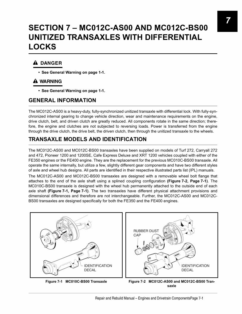
7
SECTION 7 – MC012C-AS00 AND MC012C-BS00 UNITIZED TRANSAXLES WITH DIFFERENTIAL LOCKSý DANGER
• See General Warning on page 1-1.
ý WARNING
• See General Warning on page 1-1.
GENERAL INFORMATION
The MC012C-AS00 is a heavy-duty, fully-synchronized unitized transaxle with differential lock. With fully-syn-chronized internal gearing to change vehicle direction, wear and maintenance requirements on the engine,drive clutch, belt, and driven clutch are greatly reduced. All components rotate in the same direction; there-fore, the engine and clutches are not subjected to reversing loads. Power is transferred from the enginethrough the drive clutch, the drive belt, the driven clutch, then through the unitized transaxle to the wheels.
TRANSAXLE MODELS AND IDENTIFICATION
The MC012C-AS00 and MC012C-BS00 transaxles have been supplied on models of Turf 272, Carryall 272and 472, Pioneer 1200 and 1200SE, Cafe Express Deluxe and XRT 1200 vehicles coupled with either of theFE350 engines or the FE400 engine. They are the replacement for the previous MC010C-BS00 transaxle. Alloperate the same internally, but utilize a few, slightly different gear components and have two different stylesof axle and wheel hub designs. All parts are identified in their respective illustrated parts list (IPL) manuals.The MC012C-AS00 and MC012C-BS00 transaxles are designed with a removable wheel bolt flange thatattaches to the end of the axle shaft using a splined coupling configuration (Figure 7-2, Page 7-1). TheMC010C-BS00 transaxle is designed with the wheel hub permanently attached to the outside end of eachaxle shaft (Figure 7-1, Page 7-1). The two transaxles have different physical attachment provisions anddimensional differences and therefore are not interchangeable. Further, the MC012C-AS00 and MC012C-BS00 transaxles are designed specifically for both the FE350 and the FE400 engines.
Figure 7-1 MC010C-BS00 Transaxle Figure 7-2 MC012C-AS00 and MC012C-BS00 Tran-saxle
IDENTIFICATIONDECAL
RUBBER DUST CAP
IDENTIFICATIONDECAL
Repair and Rebuild Manual – Engines and Drivetrain ComponentsPage 7-1

MC012C-AS00 AND MC012C-BS00 UNITIZED TRANSAXLES WITH DIFFERENTIAL LOCKSAxle Shaft7
Tools Required For This Section
AXLE SHAFT
See Axle Shaft and Oil Seal Removal, Section 16, in the appropriate maintenance and service manual.
UNITIZED TRANSAXLE REMOVAL
See Unitized Transaxle Removal, Section 16, in the appropriate maintenance and service manual.
UNITIZED TRANSAXLE DISASSEMBLY
See General Warning on page 1-1.
NOTE: The following information provides instructions for disassembling the unitized transaxle; however,the transaxle case can be separated and gears accessed without removing the axles or axle tubesfrom the case.
1. Position the unitized transaxle case on a clean bench surface with the bottom lubrication plug over a pansuitable for draining lubrication oil.
2. Remove both the top and bottom lubrication port plugs and gaskets. Drain and dispose of the oil properly(Figure 7-4, Page 7-3).
NOTE: The lower plug is used for draining lubricant. When draining lubricant, remove both plugs to allowthe lubricant to drain faster.
Hydraulic floor jack (or chain hoist) 12 to 18-in. straight edge 17 mm socket, 3/8-in. driveJack stands (2) (one-ton capacity) Small ball peen hammer (10 oz.) 7/16-in. combination wrenchHydraulic press Plastic or rubber mallet 1/2-in. combination wrenchBench vise Ratchet wrench, 3/8-in. drive 9/16-in. combination wrenchStandard slip joint pliers Torque wrench, 3/8-in. drive 11/16-in. combination wrench (2)External snap ring pliers (.070 in. tip) 3/8-in. Socket, 3/8-in. drive 17 mm combination wrenchExternal snap ring pliers (.047 in. tip) 7/16-in. Socket, 3/8-in. drive Small flat blade screwdriver90° Internal snap ring pliers (.090 in. tip) 10 mm Combination wrench Medium flat blade screwdrivers (2)Feeler gauge 1/2-in. Socket, 3/8-in. drive No. 2 phillips-head screwdriver16 in. rolling head prybar 9/16-in. Socket, 3/8-in. drive 1/4-in. nut driverSmall punch or scratch awl 5/8-in. Socket, 3/8-in. drive 5/16-in. nut driver1/4-in. diameter drift or metal rod 12 mm Socket, 3/8-in. drive Small knife or wire snippersBearing puller wedge attachment(CCI P/N 1012812)
Axle seal tool(CCI P/N 1014162)
Governor gear shaft installation tool (CCI P/N 101933101)
Page 7-2Repair and Rebuild Manual – Engines and Drivetrain Components
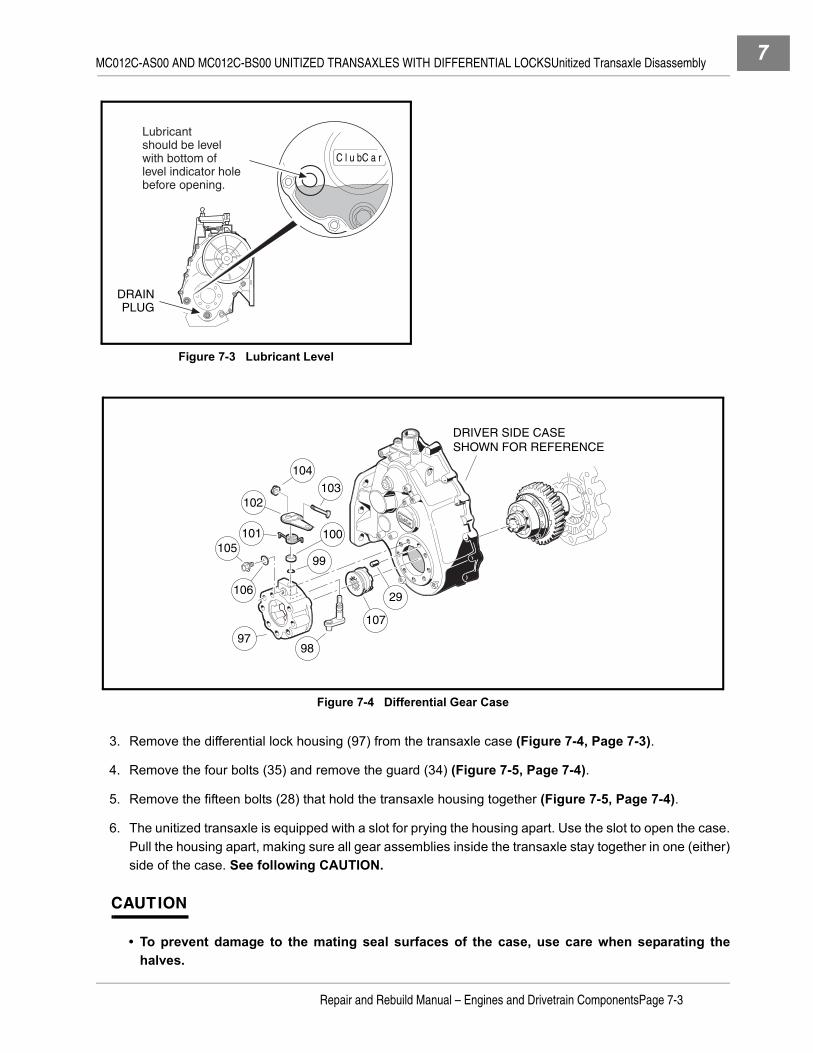
MC012C-AS00 AND MC012C-BS00 UNITIZED TRANSAXLES WITH DIFFERENTIAL LOCKSUnitized Transaxle Disassembly 7
3. Remove the differential lock housing (97) from the transaxle case (Figure 7-4, Page 7-3).
4. Remove the four bolts (35) and remove the guard (34) (Figure 7-5, Page 7-4).
5. Remove the fifteen bolts (28) that hold the transaxle housing together (Figure 7-5, Page 7-4).
6. The unitized transaxle is equipped with a slot for prying the housing apart. Use the slot to open the case.Pull the housing apart, making sure all gear assemblies inside the transaxle stay together in one (either)side of the case. See following CAUTION.
CAUTION
• To prevent damage to the mating seal surfaces of the case, use care when separating thehalves.
Figure 7-3 Lubricant Level
Figure 7-4 Differential Gear Case
DRAINPLUG
C l u b C a r
Lubricant should be level with bottom of level indicator holebefore opening.
ClubCar
DRIVER SIDE CASESHOWN FOR REFERENCE
29
107
101
103
10599
100
106
9897
102
104
Repair and Rebuild Manual – Engines and Drivetrain ComponentsPage 7-3

MC012C-AS00 AND MC012C-BS00 UNITIZED TRANSAXLES WITH DIFFERENTIAL LOCKSUnitized Transaxle Disassembly7
7. Turn the case section containing the gearing on edge as shown (Figure 7-6, Page 7-5). While holdingit in this position, gently rock all the gear assemblies to slightly loosen them in their seating. See follow-ing CAUTION.
CAUTION
• To prevent damage to the gears, use extreme care when handling them.
8. When all the gear assemblies are slightly loosened, remove the differential gear case assembly by gentlyrocking it while pulling it from the case (Figure 7-7, Page 7-5).
9. Continue to rock and loosen the remaining gear assemblies until the intermediate gear assembly can beremoved from the case. Then remove the idler shaft assembly (Figure 7-8, Page 7-5).
Figure 7-5 Transaxle Gear Casing and Brackets
ClubCar
3130
3
4
15
6
5
7
8
9
1112
13
1016
17
1822
23
2132
19
20
24
25 29
28
26
27
1
2
33
TYPICAL2 PLACES
TYPICAL15 PLACES
TYPICAL3 PLACES
2
14
3534
TYPICAL4 PLACES
Page 7-4Repair and Rebuild Manual – Engines and Drivetrain Components

MC012C-AS00 AND MC012C-BS00 UNITIZED TRANSAXLES WITH DIFFERENTIAL LOCKSUnitized Transaxle Disassembly 7
10. Remove the synchronizer gear assembly and shifter fork assembly as a unit from the case (Figure 7-8,Page 7-5).
11. Use a seal puller (CCI P/N 1012809) or rolling head prybar to remove the input shaft oil seal from thecase (Figure 7-9, Page 7-5).
12. Remove the oil flow guide from the case (Figure 7-10, Page 7-6).13. Remove the shifter shaft and oil seal from the case (Figure 7-10, Page 7-6).
13.1. Use snap ring pliers (0.047 tip) to remove the retaining ring (16) on the shifter shaft (Figure 7-5,Page 7-4).
13.2. Remove flat washer (17) from the shifter shaft on the outside of the case as shown, then removethe shifter shaft by pushing it through the case toward the interior of transaxle (Figure 7-5,Page 7-4).
13.3. Use a seal puller to remove the shifter shaft oil seal (18) from the case (Figure 7-5, Page 7-4).
Figure 7-6 Loosen Gears Figure 7-7 Remove Differential Gear Case
Figure 7-8 Remove Intermediate Gear Figure 7-9 Input Shaft Oil Seal
DIFFERENTIALGEAR CASEASSEMBLY
IDLER SHAFT ASSEMBLY
INTERMEDIATEGEAR ASSEMBLY
Remove synchronizer gear assemblyand shifter fork together as a unit.
Repair and Rebuild Manual – Engines and Drivetrain ComponentsPage 7-5

MC012C-AS00 AND MC012C-BS00 UNITIZED TRANSAXLES WITH DIFFERENTIAL LOCKSUnitized Transaxle Disassembly7
14. Remove the breather (32) from the case (Figure 7-5, Page 7-4).
15. Remove the governor assembly from the case.
15.1. Remove the cotter pin (21) and flat washer (22) from the pivot arm (25) (Figure 7-5, Page 7-4).
15.2. Remove the pivot arm (25) by pulling it through the wall to the interior of the case, along with theinside support washer (24).
15.3. Use a small chisel or similar pointed instrument to pry the pivot arm oil seal (23) (Figure 7-5,Page 7-4) out of the case (Figure 7-11, Page 7-6).
15.4. Remove the governor gear assembly (64 and 65) and flat washer (63) (Figure 7-16, Page 7-9) bylightly tapping the gear shaft through the case wall, from the outside, with a hammer and drift. Seealso Figure 7-12, Page 7-6.
Figure 7-10 Oil Flow Guide Figure 7-11 Pivot Arm Oil Seal
Figure 7-12 Remove Governor Gear
SLOT
OIL FLOW GUIDE
SHIFTER SHAFT
TAB
ClubCar
ClubCar
Page 7-6Repair and Rebuild Manual – Engines and Drivetrain Components

MC012C-AS00 AND MC012C-BS00 UNITIZED TRANSAXLES WITH DIFFERENTIAL LOCKSComponent Disassembly 7
COMPONENT DISASSEMBLYSee General Warning on page 1-1.
DIFFERENTIAL GEAR LOCK HOUSING DISASSEMBLY1. Rotate the arm (99) and remove the differential lock cog (104) (Figure 7-13, Page 7-7).2. Loosen, but do not remove, the differential lock arm retaining nut (101) and remove the arm (99) and
spring (98) from the differential lock shaft (95).3. Remove the spacer (97) from the differential lock shaft (95).4. Remove the shaft retaining screw (102) and washer (103) from the differential lock housing.5. Press the shaft (95) toward the center of the differential lock housing and remove the shaft from the hous-
ing (94).6. If necessary, gently pry the O-ring from the groove in the differential lock shaft with a small screwdriver
(Figure 7-41, Page 7-23).
GOVERNOR GEAR DISASSEMBLY
NOTE: It is not necessary to disassemble the governor gear assembly in order to install it into the tran-saxle case.
1. Secure the governor gear assembly in a vise as shown. Wrap shaft in a cloth to prevent damage(Figure 7-14, Page 7-8).
2. Use two small screwdrivers to pry the gear and flyweight off the shaft as shown.
Figure 7-13 Differential Lock Housing Disassembly
104
95
94
101
100
99
98
102
103
96
97
Repair and Rebuild Manual – Engines and Drivetrain ComponentsPage 7-7

MC012C-AS00 AND MC012C-BS00 UNITIZED TRANSAXLES WITH DIFFERENTIAL LOCKSComponent Disassembly7
DIFFERENTIAL GEAR CASE DISASSEMBLY
CAUTION
• Mark parts for identification as they are disassembled. Parts must be assembled in theiroriginal locations and orientations.
1. MC012C-AS00:1.1. Remove eight ring gear retaining bolts (70) and remove the ring gear (71) from the assembly. It may
be necessary to tap the ring gear off with a plastic or rubber mallet (Figure 7-15, Page 7-8). Seefollowing NOTE.
2. MC012C-BS00:2.1. Remove eight ring gear retaining bolts (70) and remove the ring gear (86) from the assembly. It may
be necessary to tap the ring gear off with a plastic or rubber mallet (Figure 7-16, Page 7-9). Seefollowing NOTE.
NOTE: Loctite® was applied to the bolts during assembly, it may be necessary to place the differentialgear case in a vise to remove the bolts.
Figure 7-14 Pry Gear from Shaft
Figure 7-15 Remove Ring Gear
Remove retaining bolts.
Tap around ring gear to loosen.
70
Page 7-8Repair and Rebuild Manual – Engines and Drivetrain Components

MC012C-AS00 AND MC012C-BS00 UNITIZED TRANSAXLES WITH DIFFERENTIAL LOCKSComponent Disassembly 7
Figure 7-16 MC012C-AS00 Unitized Transaxle with Differential Lock
ClubCar
REFERENCE PASSENGER SIDE
CASE
REFERENCE DRIVER SIDE
CASE
6564
63
67
66
67
61 62
60
5941
5453
4844
46
5556
4257
5851
4142
4344
4546
4748
4449
5250
394938
37
36
7271
79
78
77
74
70
69
7675
74
7378
68
40
80
Parts identification for transaxles prior to serial number MC012C3J0001
64T RING
12T PINION
Repair and Rebuild Manual – Engines and Drivetrain ComponentsPage 7-9
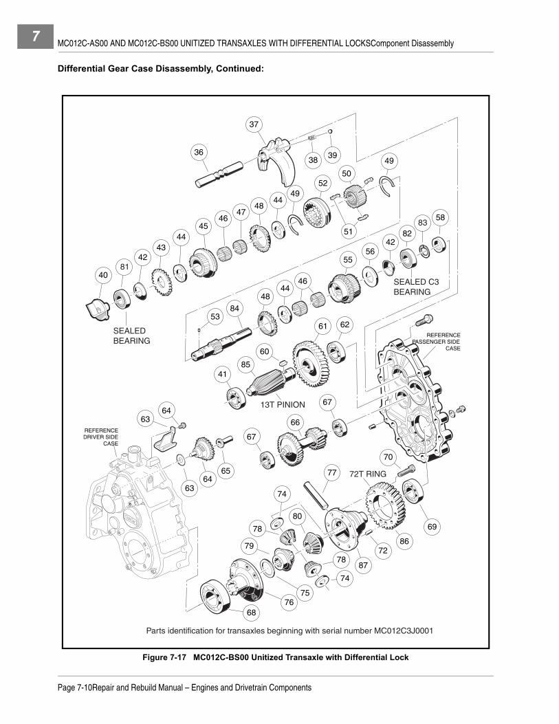
MC012C-AS00 AND MC012C-BS00 UNITIZED TRANSAXLES WITH DIFFERENTIAL LOCKSComponent Disassembly7
Differential Gear Case Disassembly, Continued:
Figure 7-17 MC012C-BS00 Unitized Transaxle with Differential Lock
ClubCar
81
6463
REFERENCE PASSENGER SIDE
CASE
REFERENCE DRIVER SIDE
CASE
6564
63
67
66
67
61 62
60
8541
8453
4844
46
5556
428251
4243
4445
4647
4844
4952
50
394938
37
36
728679
78
77
74
70
69
7675
74
8778
68
40
80
SEALEDBEARING
SEALED C3BEARING
58
81
83
Parts identification for transaxles beginning with serial number MC012C3J0001
13T PINION
72T RING
Page 7-10Repair and Rebuild Manual – Engines and Drivetrain Components

MC012C-AS00 AND MC012C-BS00 UNITIZED TRANSAXLES WITH DIFFERENTIAL LOCKSComponent Disassembly 7
3. MC012C-AS00:
3.1. Pull the cover (76) and thrust plate (75) from the differential gear carrier case (73) (Figure 7-16,Page 7-9).
3.2. Remove the differential gear (79) from the differential gear carrier case (73).
3.3. Remove the differential pin (77) (Figure 7-16, Page 7-9) by pushing it through from one side(Figure 7-18, Page 7-12).
3.4. Remove the two differential idler gears (78) and two idler gear thrust plates (74) as the pin is driventhrough the case (73) (Figure 7-16, Page 7-9). See following NOTE.
NOTE: It may be necessary to drive the differential pin out with a hammer and punch.
3.5. Remove the remaining (opposite side) differential gear (80) from the gear carrier case (73).
3.6. If bearings (68 and 69) are to be removed, place a bearing puller wedge attachment (CCI P/N1012812) between the bearing (69) and gear case (73) (Figure 7-16, Page 7-9) and press thebearing off as shown (Figure 7-19, Page 7-12). Repeat the process for the bearing (68) on the car-rier cover (76) (Figure 7-16, Page 7-9). See following CAUTION.
CAUTION
• Do not tighten the bearing puller wedge attachment against the gear case. This could damagethe gear case.
4. MC012C-BS00:
4.1. Pull the cover (76) and thrust plate (75) from the differential gear carrier case (87) (Figure 7-17,Page 7-10).
4.2. Remove the differential gear (79) from the differential gear carrier case (87).
4.3. Remove the differential pin (77) (Figure 7-17, Page 7-10) by pushing it through from one side(Figure 7-18, Page 7-12).
4.4. Remove the two differential idler gears (78) and two idler gear thrust plates (74) as the pin is driventhrough the case (87) (Figure 7-17, Page 7-10). See following NOTE.
NOTE: It may be necessary to drive the differential pin out with a hammer and punch.
4.5. Remove the remaining (opposite side) differential gear (80) from the gear carrier case (87).
4.6. If bearings (68 and 69) are to be removed, place a bearing puller wedge attachment (CCI P/N1012812) between the bearing (69) and gear case (87) (Figure 7-17, Page 7-10) and press thebearing off as shown (Figure 7-19, Page 7-12). Repeat the process for the bearing (68) on the car-rier cover (76) (Figure 7-16, Page 7-9). See following CAUTION.
CAUTION
• Do not tighten the bearing puller wedge attachment against the gear case. This could damagethe gear case.
Repair and Rebuild Manual – Engines and Drivetrain ComponentsPage 7-11

MC012C-AS00 AND MC012C-BS00 UNITIZED TRANSAXLES WITH DIFFERENTIAL LOCKSComponent Disassembly7
SHIFTER FORK DISASSEMBLY1. Push the shift rod (36) out of the shifter fork (37) (Figure 7-16, Page 7-9).
2. Shake the shifter fork (37) to remove the spring (38) and ball (39).
SYNCHRONIZER GEAR DISASSEMBLY
CAUTION
• Mark parts for identification as they are disassembled. Parts must be reassembled in theiroriginal locations and orientations.
• Do not tighten the bearing puller wedge attachment against the shaft. This could damage theshaft.
1. MC012C-AS00:1.1. Place a bearing puller wedge attachment (CCI P/N 1012812) between the bearing (41) and spur
(governor drive) gear (43) (Figure 7-16, Page 7-9), then press the bearing off the input shaft (54)as shown (Figure 7-20, Page 7-13). See preceding CAUTION.
2. MC012C-BS00:2.1. Place a bearing puller wedge attachment (CCI P/N 1012812) between the sealed bearing (81) and
spur (governor drive) gear (43) (Figure 7-17, Page 7-10), then press the bearing off the input shaft(84) as shown (Figure 7-20, Page 7-13). See preceding CAUTION.
3. Pull the spring washer (42), spur gear (43), dowel pin (53), thrust plate (44), input gear assembly (45),large needle bearing (46), small needle bearing (47), synchronizer ring (48), and thrust plate (44) fromthe input shaft (Figure 7-16, Page 7-9).
4. MC012C-AS00:4.1. Place a bearing puller wedge attachment (CCI P/N 1012812) between the bearing (57) and input
gear assembly (55) (Figure 7-16, Page 7-9), then press the bearing off the input shaft (54) asshown (Figure 7-21, Page 7-13). See following CAUTION.
5. MC012C-BS00:
Figure 7-18 Differential Pin Figure 7-19 Remove Bearing
ARBOR
PRESSRAM
WEDGEATTACHMENT
Page 7-12Repair and Rebuild Manual – Engines and Drivetrain Components

MC012C-AS00 AND MC012C-BS00 UNITIZED TRANSAXLES WITH DIFFERENTIAL LOCKSComponent Disassembly 7
5.1. Remove the external snap ring (83) from the input shaft (84) (Figure 7-17, Page 7-10).
5.2. Place a bearing puller wedge attachment (CCI P/N 1012812) between the bearing (82) and inputgear assembly (55) (Figure 7-17, Page 7-10), then press the sealed C3 bearing off the input shaft(84) as shown (Figure 7-21, Page 7-13). See following CAUTION.
CAUTION
• Do not tighten the bearing puller wedge attachment against the shaft. This could damage theshaft.
6. Pull the spring washer (42), thrust washer (56), input gear assembly (55), two needle bearings (46),thrust plate (44), and synchronizer ring (48) from the input shaft (Figure 7-16, Page 7-9).
7. Use a small flat-blade screwdriver to remove two synchronizer springs (snap rings) (49), then slide thesynchronizer clutch hub (52) from the input shaft (54) (Figure 7-16, Page 7-9). See following NOTE.
NOTE: There are three synchronizer inserts (51) set into slots in the synchronizer sleeve (50). These mayfall free when the synchronizer clutch hub (52) is removed. Do not lose these inserts.
8. Remove the three synchronizer inserts (51) from the synchronizer sleeve.
9. Press the synchronizer sleeve (50) from the input shaft.
INTERMEDIATE GEAR DISASSEMBLY1. Place a bearing puller wedge attachment (CCI P/N 1012812) between bearing (41) and shaft/pinion gear
(59) (Figure 7-16, Page 7-9), then press bearing off shaft (Figure 7-22, Page 7-14). See followingCAUTION.
CAUTION
• Do not tighten the bearing puller wedge attachment against the shaft. This could damage theshaft.
Figure 7-20 Remove Bearing Figure 7-21 Remove Bearing
ARBOR
PRESSRAM
WEDGEATTACHMENT
PRESS RAM
BEARING PULLERWEDGE ATTACHMENT
Repair and Rebuild Manual – Engines and Drivetrain ComponentsPage 7-13

MC012C-AS00 AND MC012C-BS00 UNITIZED TRANSAXLES WITH DIFFERENTIAL LOCKSComponent Disassembly7
2. Place the bearing puller wedge attachment under the bearing (62) and press the bearing from the shaft(Figure 7-16, Page 7-9). See preceding CAUTION.
3. Press the gear (61) from the shaft (59), then remove the key (60).
IDLER SHAFT DISASSEMBLY1. Place a bearing puller wedge attachment (CCI P/N 1012812) between the bearing (67) (Figure 7-16,
Page 7-9) and the small gear on the idler shaft (66), then press the bearing off the shaft (Figure 7-23,Page 7-14). See following CAUTION.
CAUTION
• Do not tighten the bearing puller wedge attachment against the shaft. The shaft could bedamaged when pressing the bearing off.
2. Place a bearing puller wedge attachment (CCI P/N 1012812) between the bearing and the larger gearon the idler shaft (66) (Figure 7-16, Page 7-9), then press the bearing off the shaft as shown(Figure 7-24, Page 7-14).
Figure 7-22 Remove Bearing Figure 7-23 Remove Bearing
Figure 7-24 Remove Idler Shaft Figure 7-25 Inspect Bearings
ARBOR
PRESSRAM
WEDGEATTACHMENT
ARBOR
PRESS RAM
ARBOR
PRESS RAM
WEDGEATTACHMENT
A B
Page 7-14Repair and Rebuild Manual – Engines and Drivetrain Components

MC012C-AS00 AND MC012C-BS00 UNITIZED TRANSAXLES WITH DIFFERENTIAL LOCKSUnitized Transaxle Component In-spection
7
UNITIZED TRANSAXLE COMPONENT INSPECTION
See General Warning on page 1-1.
1. Clean all of the component parts of the transaxle in a high flash-point solvent and then dry them. Inspectall components for excessive wear or damage.
2. Inspect all bearings by spinning them by hand. Check the bearings for excessive axial (A) and radial (B)play (Figure 7-25, Page 7-14). Replace bearings if they do not spin smoothly, if they are noisy, or if theyhave excessive play. Replace bearings if they are rusted, worn, cracked, pitted or discolored.
3. Gears should be inspected for tooth surface damage or fractures.
4. Synchronizer ring teeth should be inspected for severe wear, fractures, or other damage.
5. Using a feeler gauge, measure the distance X at several points around the assembly. The synchro ringshould be replaced when X is 0.02 inch (0.5 mm) or less (Figure 7-26, Page 7-15).
6. Inspect the O-ring (96) on the differential lock shaft (Figure 7-13, Page 7-7).
COMPONENT ASSEMBLY
See on page 1-1.
IDLER SHAFT ASSEMBLY
1. Press a new bearing (67) (Figure 7-16, Page 7-9) onto each end of the idler shaft (Figure 7-27,Page 7-15). See following CAUTION.
CAUTION
• Apply pressure against the inner race of the bearing only. Applying pressure anywhere elsewill damage the bearing.
Figure 7-26 Synchronizer Ring Figure 7-27 Idler Shaft
X Press bearingonto idler shaft.
Turn idler shaft over and press
bearing onother end.
B
A
Repair and Rebuild Manual – Engines and Drivetrain ComponentsPage 7-15

MC012C-AS00 AND MC012C-BS00 UNITIZED TRANSAXLES WITH DIFFERENTIAL LOCKSComponent Assembly7
INTERMEDIATE GEAR ASSEMBLY1. If the gear (61) was removed from the shaft, install the key (60) into the slot and then position the gear
on the shaft with keyway properly aligned with key. Press gear into place on the key (Figure 7-16,Page 7-9).
2. Press the bearing (62) onto the end of the shaft next to the large gear that was installed in step one. Seefollowing CAUTION.
CAUTION
• Apply pressure against the inner race of the bearing only. Applying pressure anywhere elsewill damage the bearing.
3. Press a new bearing (41) onto the other end of the shaft.
SYNCHRONIZER GEAR ASSEMBLY1. MC012C-AS00:
1.1. Press the synchronizer sleeve (50) onto the splines of the input shaft (54) (Figure 7-16, Page 7-9).No particular orientation of the sleeve is necessary, but toward the short end of the shaft, themachined circular face surrounding the ends of the internal splines in the sleeve must be flush withthe machined lip of the shaft at the ends of the shaft splines (Figure 7-28, Page 7-16).
1.2. Install the synchronizer springs (49) (Figure 7-16, Page 7-9) in the sleeve (Figure 7-29,Page 7-16).
NOTE: Make sure the ends of the springs are positioned between the synchronizer insert slots(Figure 7-29, Page 7-16).
1.3. Install the three synchronizer inserts (51) into the slots in the sleeve (Figure 7-16, Page 7-9). Makesure the notched surfaces of the inserts are facing outward (Figure 7-30, Page 7-18).
1.4. Install the synchronizer clutch hub (52) (Figure 7-16, Page 7-9) onto the synchronizer sleeve.Make sure the chamfered end of the hub is oriented toward the long end of the input shaft(Figure 7-31, Page 7-18).
Figure 7-28 Synchronizer Gear Assembly Figure 7-29 Synchronizer Springs
PRESSRAM
SYNCHRONIZERSLEEVE
INPUTSHAFT
MACHINEDFACE OF
SYNCHRO.SLEEVE
TOP OF SPLINE
Top of spline pressed level with machined
face.
Install springson top and bottomof synchronizersleeve as shown.
Endspositioned
betweeninsert slots.
FRONT VIEW
SYNCHRONIZER INSERT SLOTS
Page 7-16Repair and Rebuild Manual – Engines and Drivetrain Components

MC012C-AS00 AND MC012C-BS00 UNITIZED TRANSAXLES WITH DIFFERENTIAL LOCKSComponent Assembly 7
1.5. On the long end of the shaft (54), install the synchronizer ring (48) (Figure 7-16, Page 7-9) with thesmooth collar of the ring towards the clutch hub. Make sure the three notches in the collar mate withthe synchronizer inserts in the synchronizer sleeve (Figure 7-32, Page 7-19).
1.6. Install the thrust washer (44) and two bearings (46) (Figure 7-16, Page 7-9).1.7. Install the input gear assembly (55), with the smooth collar toward the synchronizer ring. The input
gear should seat in the synchronizer ring.1.8. Install the thrust washer (56) and then the spring washer (42). The spring washer should be ori-
ented with the raised center toward the end of the shaft.1.9. Press a new bearing (57) onto the shaft until it seats. Make sure the input gear turns freely. See fol-
lowing CAUTION.
CAUTION
• Apply pressure against the inner race of the bearing only. Applying pressure anywhere elsewill damage the bearing.
1.10. On the other end of the input shaft (54), install one thrust washer (44), and the synchronizer ring(48) (Figure 7-16, Page 7-9). The smooth collar of the synchronizer ring should be oriented towardthe clutch hub, and the notches in it should mate with the synchronizer inserts as shown(Figure 7-31, Page 7-18).
1.11. Install the narrow bearing (47), wide bearing (46), and input gear (45) onto the shaft. The smoothcollar of the input gear should be oriented toward the synchronizer ring (Figure 7-16, Page 7-9).The gear should seat inside the ring.
1.12. Install remaining thrust washer (44) onto the shaft and the dowel pin (53) into the shaft (54) asshown.
1.13. Install the spur (governor drive) gear (43) onto the shaft with either side down. Mate the notch in thegear with the dowel pin as shown.
1.14. Install the spring washer (42) onto shaft with the raised center toward the end of the shaft.1.15. Press a new bearing (41) onto the end of the shaft until it seats (Figure 7-16, Page 7-9). Make sure
the input gears turn freely. See following CAUTION.
CAUTION
• Apply pressure against the inner race of the bearing only. Applying pressure anywhere elsewill damage the bearing.
2. MC012C-BS00:2.1. Press the synchronizer sleeve (50) onto the splines of the input shaft (84) (Figure 7-17,
Page 7-10). No particular orientation of the sleeve is necessary, but toward the short end of theshaft, the machined circular face surrounding the ends of the internal splines in the sleeve must beflush with the machined lip of the shaft at the ends of the shaft splines (Figure 7-28, Page 7-16).
2.2. Install the synchronizer springs (49) (Figure 7-17, Page 7-10) in the sleeve (Figure 7-29,Page 7-16).
NOTE: Make sure the ends of the springs are positioned between the synchronizer insert slots(Figure 7-29, Page 7-16).
2.3. Install the three synchronizer inserts (51) into the slots in the sleeve (Figure 7-17, Page 7-10).Make sure the notched surfaces of the inserts are facing outward (Figure 7-30, Page 7-18).
2.4. Install the synchronizer clutch hub (52) (Figure 7-17, Page 7-10) onto the synchronizer sleeve.Make sure the chamfered end of the hub is oriented toward the long end of the input shaft(Figure 7-31, Page 7-18).
Repair and Rebuild Manual – Engines and Drivetrain ComponentsPage 7-17

MC012C-AS00 AND MC012C-BS00 UNITIZED TRANSAXLES WITH DIFFERENTIAL LOCKSComponent Assembly7
2.5. On the long end of the shaft (84), install the synchronizer ring (48) (Figure 7-17, Page 7-10) withthe smooth collar of the ring towards the clutch hub. Make sure the three notches in the collar matewith the synchronizer inserts in the synchronizer sleeve (Figure 7-32, Page 7-19).
2.6. Install the thrust washer (44) and two bearings (46) (Figure 7-17, Page 7-10).2.7. Install the input gear assembly (55), with the smooth collar toward the synchronizer ring. The input
gear should seat in the synchronizer ring.2.8. Install the thrust washer (56) and then the spring washer (42). The spring washer should be ori-
ented with the raised center toward the end of the shaft.2.9. Press a new sealed C3 bearing (82) onto the shaft until it seats. Make sure the input gear turns
freely. See following CAUTION.
CAUTION
• Apply pressure against the inner race of the bearing only. Applying pressure anywhere elsewill damage the bearing.
2.10. Install the external snap ring (83) on the shaft (84).2.11. On the other end of the input shaft (84), install one thrust washer (44), and the synchronizer ring
(48) (Figure 7-17, Page 7-10). The smooth collar of the synchronizer ring should be orientedtoward the clutch hub, and the notches in it should mate with the synchronizer inserts as shown(Figure 7-31, Page 7-18).
2.12. Install the narrow bearing (47), wide bearing (46), and input gear (45) onto the shaft. The smoothcollar of the input gear should be oriented toward the synchronizer ring (Figure 7-17, Page 7-10).The gear should seat inside the ring.
2.13. Install remaining thrust washer (44) onto the shaft and the dowel pin (53) into the shaft (54) asshown.
2.14. Install the spur (governor drive) gear (43) onto the shaft with either side down. Mate the notch in thegear with the dowel pin as shown.
2.15. Install the spring washer (42) onto shaft with the raised center toward the end of the shaft.2.16. Press a new sealed bearing (81) onto the end of the shaft until it seats (Figure 7-17, Page 7-10).
Make sure the input gears turn freely. See following CAUTION.
CAUTION
• Apply pressure against the inner race of the bearing only. Applying pressure anywhere elsewill damage the bearing.
Figure 7-30 Synchronizer Inserts Figure 7-31 Synchronizer Clutch Hub
Synchronizer inserts overlap springs.
TOP VIEW
Notchedsurfacesof synchro.inserts faceout. SPRINGS TOP AND BOTTOM
SIDE VIEW
CHAMFERED ON ENDOF CLUTCH HUB
LONG END OF SHAFT
SYNCHRONIZERSLEEVE
SYNCHRONIZERCLUTCH HUB
Page 7-18Repair and Rebuild Manual – Engines and Drivetrain Components

MC012C-AS00 AND MC012C-BS00 UNITIZED TRANSAXLES WITH DIFFERENTIAL LOCKSComponent Assembly 7
SHIFTER FORK ASSEMBLY
1. Install the spring (35) and ball (36) into the shifter fork (34) as shown (Figure 7-33, Page 7-19).
2. Use a no. 1 tip phillips screwdriver to press the ball and spring while inserting shift rod (33) into the shifterfork (34) (Figure 7-34, Page 7-19). Remove screwdriver when the shift rod is inserted far enough for itto depress the ball and spring, then continue to insert rod until the ball is positioned in the middle detenton the rod.
Figure 7-32 Synchronizer Ring
Figure 7-33 Align Spring and Ball and Insert Figure 7-34 Insert Shift Rod Past Ball
SYNCHRONIZERRING
SYNCHRONIZERCLUTCH HUB
3334
34
35
35
36
36
3334
34
3536
Repair and Rebuild Manual – Engines and Drivetrain ComponentsPage 7-19
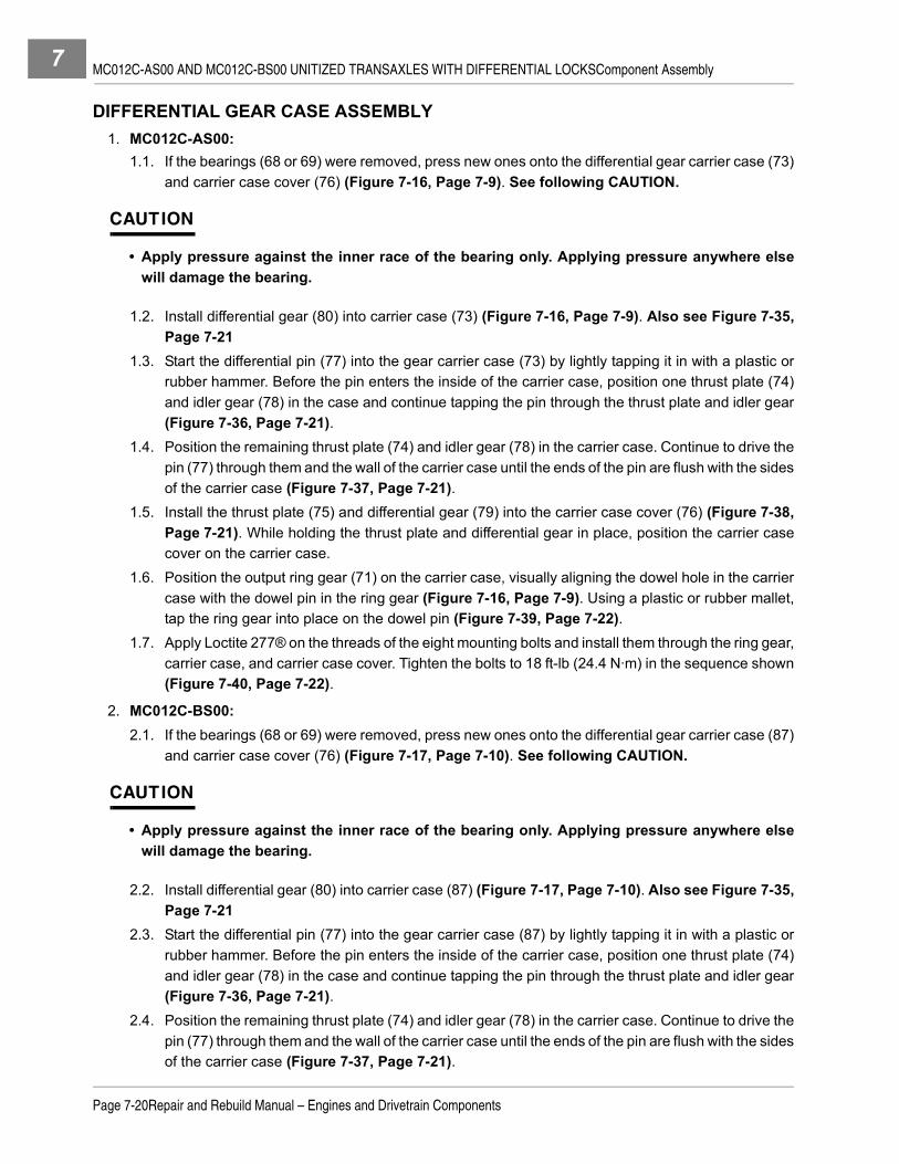
MC012C-AS00 AND MC012C-BS00 UNITIZED TRANSAXLES WITH DIFFERENTIAL LOCKSComponent Assembly7
DIFFERENTIAL GEAR CASE ASSEMBLY1. MC012C-AS00:
1.1. If the bearings (68 or 69) were removed, press new ones onto the differential gear carrier case (73)and carrier case cover (76) (Figure 7-16, Page 7-9). See following CAUTION.
CAUTION
• Apply pressure against the inner race of the bearing only. Applying pressure anywhere elsewill damage the bearing.
1.2. Install differential gear (80) into carrier case (73) (Figure 7-16, Page 7-9). Also see Figure 7-35,Page 7-21
1.3. Start the differential pin (77) into the gear carrier case (73) by lightly tapping it in with a plastic orrubber hammer. Before the pin enters the inside of the carrier case, position one thrust plate (74)and idler gear (78) in the case and continue tapping the pin through the thrust plate and idler gear(Figure 7-36, Page 7-21).
1.4. Position the remaining thrust plate (74) and idler gear (78) in the carrier case. Continue to drive thepin (77) through them and the wall of the carrier case until the ends of the pin are flush with the sidesof the carrier case (Figure 7-37, Page 7-21).
1.5. Install the thrust plate (75) and differential gear (79) into the carrier case cover (76) (Figure 7-38,Page 7-21). While holding the thrust plate and differential gear in place, position the carrier casecover on the carrier case.
1.6. Position the output ring gear (71) on the carrier case, visually aligning the dowel hole in the carriercase with the dowel pin in the ring gear (Figure 7-16, Page 7-9). Using a plastic or rubber mallet,tap the ring gear into place on the dowel pin (Figure 7-39, Page 7-22).
1.7. Apply Loctite 277® on the threads of the eight mounting bolts and install them through the ring gear,carrier case, and carrier case cover. Tighten the bolts to 18 ft-lb (24.4 N·m) in the sequence shown(Figure 7-40, Page 7-22).
2. MC012C-BS00:2.1. If the bearings (68 or 69) were removed, press new ones onto the differential gear carrier case (87)
and carrier case cover (76) (Figure 7-17, Page 7-10). See following CAUTION.
CAUTION
• Apply pressure against the inner race of the bearing only. Applying pressure anywhere elsewill damage the bearing.
2.2. Install differential gear (80) into carrier case (87) (Figure 7-17, Page 7-10). Also see Figure 7-35,Page 7-21
2.3. Start the differential pin (77) into the gear carrier case (87) by lightly tapping it in with a plastic orrubber hammer. Before the pin enters the inside of the carrier case, position one thrust plate (74)and idler gear (78) in the case and continue tapping the pin through the thrust plate and idler gear(Figure 7-36, Page 7-21).
2.4. Position the remaining thrust plate (74) and idler gear (78) in the carrier case. Continue to drive thepin (77) through them and the wall of the carrier case until the ends of the pin are flush with the sidesof the carrier case (Figure 7-37, Page 7-21).
Page 7-20Repair and Rebuild Manual – Engines and Drivetrain Components

MC012C-AS00 AND MC012C-BS00 UNITIZED TRANSAXLES WITH DIFFERENTIAL LOCKSComponent Assembly 7
2.5. Install the thrust plate (75) and differential gear (79) into the carrier case cover (76) (Figure 7-38,Page 7-21). While holding the thrust plate and differential gear in place, position the carrier casecover on the carrier case.
2.6. Position the output ring gear (86) on the carrier case, visually aligning the dowel hole in the carriercase with the dowel pin in the ring gear (Figure 7-17, Page 7-10). Using a plastic or rubber mallet,tap the ring gear into place on the dowel pin (Figure 7-39, Page 7-22).
2.7. Apply Loctite 277® on the threads of the eight mounting bolts and install them through the ring gear,carrier case, and carrier case cover. Tighten the bolts to 18 ft-lb (24.4 N·m) in the sequence shown(Figure 7-40, Page 7-22).
Figure 7-35 Differential Gear Figure 7-36 Idler Gear
Figure 7-37 Second Idler Gear Figure 7-38 Carrier Case
DIFFERENTIALGEAR CARRIERCASE
77
7874
787774
76
79
75
Repair and Rebuild Manual – Engines and Drivetrain ComponentsPage 7-21
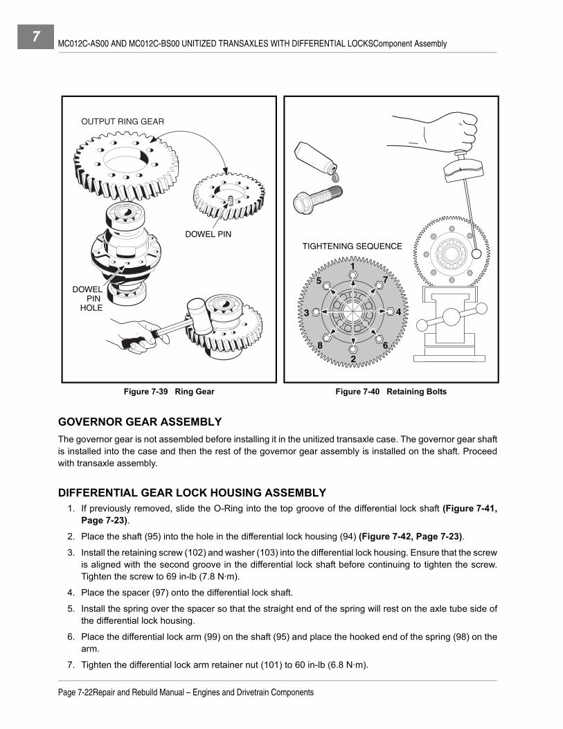
MC012C-AS00 AND MC012C-BS00 UNITIZED TRANSAXLES WITH DIFFERENTIAL LOCKSComponent Assembly7
GOVERNOR GEAR ASSEMBLYThe governor gear is not assembled before installing it in the unitized transaxle case. The governor gear shaftis installed into the case and then the rest of the governor gear assembly is installed on the shaft. Proceedwith transaxle assembly.
DIFFERENTIAL GEAR LOCK HOUSING ASSEMBLY1. If previously removed, slide the O-Ring into the top groove of the differential lock shaft (Figure 7-41,
Page 7-23).
2. Place the shaft (95) into the hole in the differential lock housing (94) (Figure 7-42, Page 7-23).
3. Install the retaining screw (102) and washer (103) into the differential lock housing. Ensure that the screwis aligned with the second groove in the differential lock shaft before continuing to tighten the screw.Tighten the screw to 69 in-lb (7.8 N·m).
4. Place the spacer (97) onto the differential lock shaft.
5. Install the spring over the spacer so that the straight end of the spring will rest on the axle tube side ofthe differential lock housing.
6. Place the differential lock arm (99) on the shaft (95) and place the hooked end of the spring (98) on thearm.
7. Tighten the differential lock arm retainer nut (101) to 60 in-lb (6.8 N·m).
Figure 7-39 Ring Gear Figure 7-40 Retaining Bolts
DOWEL PIN
DOWELPIN
HOLE
OUTPUT RING GEAR
TIGHTENING SEQUENCE
1
2
3 4
5
6
7
8
Page 7-22Repair and Rebuild Manual – Engines and Drivetrain Components

MC012C-AS00 AND MC012C-BS00 UNITIZED TRANSAXLES WITH DIFFERENTIAL LOCKSUnitized Transaxle Assembly 7
UNITIZED TRANSAXLE ASSEMBLY
See General Warning on page 1-1.
NOTE: Although the following drawings show the transaxle being assembled in an upright position, layingthe transaxle on its left (driver) side will simplify the assembly process.
1. Make sure both parts of the case are clean and free of any contaminants. Make sure the machined mat-ing surfaces are free of residue and are not scratched or damaged in any way.
2. Put a light coating of clean transmission oil on the outside edge of the seal to make installation easier.Press two new oil seals (18 and 23) (Figure 7-5, Page 7-4) into the top of the left (driver) side case. Usean oil seal installation tool (CCI P/N 1014160) to install a new oil seal (58) (Figure 7-16, Page 7-9) intothe right (passenger side) case. See also Figure 7-43, Page 7-24.
3. Position the governor gear shaft installation tool (CCI P/N 101933101) over the shaft bore in the insideof the left (driver) side case and insert the governor gear shaft into the tool, long end (from the groove)first, as shown (Figure 7-44, Page 7-24). Make sure the shaft is started into the bore, then using a plasticor rubber hammer, carefully tap the governor gear shaft into the bore until the end being tapped is flushwith the end of the tool. Remove installation tool.
4. Install the washer, governor gear, and sleeve together onto the governor shaft (Figure 7-45, Page 7-25).Make sure the sleeve is properly positioned within the flyweight brackets of the gear (Figure 7-46,Page 7-25), then push them onto the shaft until the gear snaps into the groove on the shaft.
5. Position the interior washer on the pivot arm and install the pivot arm and washer into the left (driver side)case (Figure 7-47, Page 7-25). Install the exterior washer and cotter pin on the pivot arm outside thecase. Bend the legs of the cotter pin.
6. Install the shifter shaft into the left (driver side) case (Figure 7-48, Page 7-25). Install the washer and useexternal snap ring pliers (0.070 tip) to install retaining ring on the shifter shaft outside of the case. Makesure the retaining ring is in the groove of the shaft.
Figure 7-41 Differential Lock Shaft Figure 7-42 Differential Lock Housing Assembly
O-RING GROOVE
RETAINING SCREWGROOVE
10495
94
101
100
99
98102
103
96
97
Repair and Rebuild Manual – Engines and Drivetrain ComponentsPage 7-23

MC012C-AS00 AND MC012C-BS00 UNITIZED TRANSAXLES WITH DIFFERENTIAL LOCKSUnitized Transaxle Assembly7
7. Install the gear assemblies into the left (driver side) case.
7.1. Stand the left (driver) side case on the mounting plate, then install the differential gear case assem-bly (Figure 7-49, Page 7-26). Do not seat the assembly in the bore. Instead, insert it far enoughthat it will not fall out.
7.2. Install the idler gear assembly into case. Do not seat the assembly in the bore. Instead, insert farenough that it will not fall out. No gears mesh at this point (Figure 7-50, Page 7-26).
7.3. Install the oil guide with the baffle toward the case wall (Figure 7-51, Page 7-26). Make sure thetwo tabs on the guide are positioned in the slots in the case.
Figure 7-43 Install Seals Figure 7-44 Governor Gear Shaft
ClubCar
Press oil sealinto right sidecase.
SHAFT
TOOL
Page 7-24Repair and Rebuild Manual – Engines and Drivetrain Components

MC012C-AS00 AND MC012C-BS00 UNITIZED TRANSAXLES WITH DIFFERENTIAL LOCKSUnitized Transaxle Assembly 7
Figure 7-45 Position Governor Gear Figure 7-46 Install Governor Gear
Figure 7-47 Pivot Arm Figure 7-48 Insert Shifter Shaft
SLEEVE
GOVERNORGEARWASHER
INSIDE VIEW OF LEFT SIDE CASING
EXTERIOR WASHER
COTTER PIN
INTERIOR WASHER
GOVERNOR ARM
Insert shifter shaft from inside of left side casing.
RETAININGRINGWASHER
Repair and Rebuild Manual – Engines and Drivetrain ComponentsPage 7-25

MC012C-AS00 AND MC012C-BS00 UNITIZED TRANSAXLES WITH DIFFERENTIAL LOCKSUnitized Transaxle Assembly7
Figure 7-49 Differential Gear Assembly Figure 7-50 Idler Gear Assembly
Figure 7-51 Oil Guide Figure 7-52 Synchronizer Ring Gear
DIFFERENTIALGEAR ASSEMBLY
IDLER GEAR ASSEMBLY
SLOTTAB
Cutaway view of shifter fork and synchronizer gear assembly beinginserted as a unit into casing.
Page 7-26Repair and Rebuild Manual – Engines and Drivetrain Components

MC012C-AS00 AND MC012C-BS00 UNITIZED TRANSAXLES WITH DIFFERENTIAL LOCKSUnitized Transaxle Assembly 7
7.4. Position the shifter fork assembly on the synchronizer gear assembly and install them together,bearing end first, into the bore containing the oil guide (Figure 7-52, Page 7-26). Do not seat theassembly, but make sure the spur gear (43) is meshed with the governor gear (64) (Figure 7-16,Page 7-9), and the shifter lever (19) (Figure 7-5, Page 7-4) is positioned in the bracket on theshifter fork. See also Figure 7-53, Page 7-27.
7.5. Install the intermediate gear assembly into the case (Figure 7-54, Page 7-27). Do not seat theassembly into the bore. Instead make sure the output ring gear meshes with the input drive gear(55) on the synchronizer gear assembly and with the small gear on the idler shaft (66) (Figure 7-16,Page 7-9).
7.6. Keep the gears meshed as a group and work all of the gear assemblies into the bores until they areseated. When all of the assemblies are correctly seated, the outside edges of the input drive gear(55) and the intermediate gear (61) (Figure 7-16, Page 7-9) should be flush (on the same plane)(Figure 7-55, Page 7-28). Also, the outside surfaces of the idler gear bearing, the intermediategear bearing, and the differential gear bearing should be flush (Figure 7-55, Page 7-28). See fol-lowing CAUTION.
CAUTION
• If the edges of the input drive gear and intermediate gear are not flush, then the oil guide (40)(Figure 7-16, Page 7-9) may not be properly positioned in the bore.
8. Make sure the mating surfaces of the left and right sides of the case are clean and free of oil, grease, orresidue of any kind, and they are not scratched or damaged in any way.
Figure 7-53 Gear Alignment Figure 7-54 Gear Alignment
As you insert the synchronizer gearassembly (complete with shifter fork)into the casing, several gearsmust mesh together.
Large idler gear and synchronizergear mesh.
Spur gear andgovernor gearmesh.
Shifter arm and theshifter fork slottedarm also mesh.
SHIFTERFORK The small gear on the
intermediate gearassembly meshes with the differential ring gear.
DIFFERENTIALRING GEAR
SYNCHRONIZERINPUT DRIVE GEAR
SMALL IDLER GEAR
Several gears meshas you insert theintermediate gearassembly.
(These three gears mesh.)
LARGEINTERMEDIATEGEAR
Repair and Rebuild Manual – Engines and Drivetrain ComponentsPage 7-27

MC012C-AS00 AND MC012C-BS00 UNITIZED TRANSAXLES WITH DIFFERENTIAL LOCKSUnitized Transaxle Assembly7
9. Apply a continuous bead of Three Bond No. 1215 (CCI P/N 101928701) sealant to the mating surface,around the complete profile of the right (passenger side) case (Figure 7-56, Page 7-28). See followingCAUTION.
CAUTION
• Use only Three Bond No. 1215 sealant to seal case. Do not use a substitute.
• If the two sides of the case cannot be easily closed or do not make complete contact, do notforce them together. Check that all internal components are properly seated and then tryagain.
10. Install and finger-tighten the fifteen bolts (28) (Figure 7-5, Page 7-4) that secure the left and right sidesof the case together. Then, in sequence shown, tighten the bolts to 17 ft-lb (23.1 N·m) (Figure 7-57,Page 7-28).
Figure 7-55 Assembly Gear Alignment Figure 7-56 Prepare Mating Surfaces
Figure 7-57 Casing Torque Sequence
The outside edges of the idler, intermediate,and differential bearings are on the same plane.The synchronizer bearing protrudes slightly.
The edges of the inputdrive gear and largeintermediate gearshould be flush.
EDGESFLUSH
MATING SURFACES
13
5
6
7
8
9
11
13
14
15
42 10
12
Page 7-28Repair and Rebuild Manual – Engines and Drivetrain Components

MC012C-AS00 AND MC012C-BS00 UNITIZED TRANSAXLES WITH DIFFERENTIAL LOCKSAxle Tubes 7
AXLE TUBES
See Axle Tube Installation, Section 16, in the appropriate maintenance and service manual.
UNITIZED TRANSAXLE INSTALLATION
See Unitized Transaxle Installation, Section 16, in the appropriate maintenance and service manual.
LUBRICATION
See Lubrication, Section 16, in the appropriate maintenance and service manual.
Repair and Rebuild Manual – Engines and Drivetrain ComponentsPage 7-29

7

8
SECTION 8 – TRANSMISSION MODELS 420317 AND 420682ý DANGER
• See General Warning on page 1-1.
ý WARNING
• See General Warning on page 1-1.
GENERAL INFORMATION
The 420317 and 420682 model transmissions are designed for both forward and reverse power with splinedinput, front and rear output shafts.
MODEL IDENTIFICATION
The gasoline engine transmission (Model 420317) is equipped with a governing ground speed control feature.The diesel engine transmission (Model 420682) does not have a governing ground speed control feature.With the exception of the governing ground speed control, both transmissions are identical. The proceduresin this manual can be used for both transmissions (Figure 8-1, Page 8-1).
SERVICE FIXTURE
Before disassembly and assembly of either transmission it is recommended that a fixture be constructed tohold the transmission in place. A simple wooden fixture can be made and clamped or fastened to a cleanworking surface or bench top (Figure 8-2, Page 8-2).
Figure 8-1 Transmission with Ground Speed Governor
Repair and Rebuild Manual – Engines and Drivetrain ComponentsPage 8-1

TRANSMISSION MODELS 420317 AND 420682Transmission Removal8
Service Fixture, Continued:
Tools Required For This Section
TRANSMISSION REMOVAL
See Transmission Removal, Section 14, in the appropriate maintenance and service manual.
TRANSMISSION DISASSEMBLY
See General Warning on page 1-1.1. Position the transmission case on the service fixture with the drain plug over the right side edge allowing
the transmission base to rest on the fixture. Remove the drain plug at the base of the housing and drainand dispose of the oil properly (Figure 8-3, Page 8-3).
Figure 8-2 Wooden Service Fixture
Hydraulic press Plastic or rubber mallet 7/16 in. combination wrenchExternal snap ring pliers (.070 in. tip) Ratchet wrench, 3/8 in. drive 1/2 in. combination wrenchExternal snap ring pliers (.047 in. tip) Torque wrench, 3/8 in. drive 9/16 in. combination wrenchBearing puller wedge attachment(CCI 1012812) 12 mm Socket, 3/8 in. drive Small flat blade screwdriver
Medium flat blade screwdriver No. 2 phillips head screwdriver
11 INCHES
5-1/2 INCHES
5-1/2 INCHES
1-1/4 INCH
(2) 2 x 4 FUR
(2) 1 x 2 x 6 INCH LONG PINE
4 INCHES
16 INCHES
1 INCH (Typical)
1-1/2 INCHES (Typical)
3-1/2 INCHES (Typical)
(12) 1-1/2 INCH DRYWALL SCREWS WITH GLUE Typical 4 locations
(4) 1-1/2 INCH DRYWALL SCREWSWITH GLUE Typical 2 locations
3/4 INCH PLYWOOD
(2) 1 x 4 PINE
DIA. HOLE
1/4 x 1-1/2 PINE
(3) #6 x 3/4 INCH SHEET METAL SCREWSWITH GLUE
Page 8-2Repair and Rebuild Manual – Engines and Drivetrain Components

TRANSMISSION MODELS 420317 AND 420682Transmission Disassembly 8
2. Position a service fixture, built like the one illustrated, with the through hole for the output shaft locatedto the right on a work bench. Clamp or secure the fixture to a work bench surface. Position the transmis-sion housing with the front output shaft down and the housing bolt heads up (Figure 8-4, Page 8-3). Seefollowing NOTE.
NOTE: It will be easier to disassemble and assemble the transmission if a fixture like or similar to the oneillustrated is provided. The transmission case must be secure on a flat surface with the front outputshaft in a downward position.
3. Remove hex-head case bolts (Figure 8-5, Page 8-3).
4. Separate the case halves. See following NOTE.
NOTE: Use pry bars or two box-end wrenches positioned back to back then squeezing the two together,leveraging the ends in opposing directions forcing the case halves apart (Figure 8-6, Page 8-4).
5. Remove the neutral sensing switch, plunger and spring from the case (Figure 8-7, Page 8-4).
6. Remove the top half of the case (Figure 8-8, Page 8-4).
Figure 8-3 Drain Transmission Oil
Figure 8-4 Position Case on Fixture Figure 8-5 Remove Case Bolts
Repair and Rebuild Manual – Engines and Drivetrain ComponentsPage 8-3

TRANSMISSION MODELS 420317 AND 420682Transmission Disassembly8
7. Remove the input shaft, gear and ground speed governor assembly (Figure 8-9, Page 8-4). See fol-lowing NOTES.
NOTE: Observe the location of the ground speed governor yoke bracket on the governor control.
The input shaft bearing next to the ground speed governor control is press fit into the back casecavity and slip fit onto the input shaft journal. The input shaft bearing next to the input helical gearand front case is slip fit into the case cavity and press fit onto the input shaft journal.
8. Remove the ground speed governor yoke bracket from the governor shaft (Figure 8-10, Page 8-5).
9. Remove the ground speed governor shaft and seal from the case by tapping gently with a small hammerfrom inside the case (Figure 8-11, Page 8-5). See following CAUTION.
Figure 8-6 Separate Case Halves Figure 8-7 Neutral Sensing Switch
Figure 8-8 Remove Top Half of Case Figure 8-9 Input Shaft, Gear and Governor Assembly
Page 8-4Repair and Rebuild Manual – Engines and Drivetrain Components

TRANSMISSION MODELS 420317 AND 420682Transmission Disassembly 8
CAUTION
• Removing the seal may require replacing it with a new one.
10. Remove the input shaft bearing from the case cavity (Figure 8-12, Page 8-5).
11. Press the input shaft helical gear bearing from the shaft if the bearing is worn or damaged and replacewith a new bearing. See Input Shaft Disassembly on page 8-8. See following CAUTION.
CAUTION
• If the input shaft helical gear bearing is removed for any reason, either with a press or with abearing puller, the bearing must be replaced with a new bearing.
12. Lift the intermediate and output shafts and gear assemblies slightly so that the shaft bearings are freefrom the back side case.
Figure 8-10 Ground Speed Governor Yoke Bracket Figure 8-11 Ground Speed Governor Shaft
Figure 8-12 Remove Input Shaft Bearing from Case
Repair and Rebuild Manual – Engines and Drivetrain ComponentsPage 8-5

TRANSMISSION MODELS 420317 AND 420682Transmission Disassembly8
13. Hold the shafts and gear assemblies up and move them away from the engagement gear fork.
14. Rotate the bell crank arm downward allowing the shifter fork and gear fork shaft pin to separate
(Figure 8-13, Page 8-6).
15. Lift the gear fork from the transmission (Figure 8-14, Page 8-6). See following NOTE.
NOTE: The large end of the shifter fork yoke operates the engagement gear on the intermediate shaft. It
is not necessary to remove the shifter arm on the case to remove the fork (Figure 8-14, Page 8-6).
16. Lift the intermediate and output shafts and gear assemblies from the case (Figure 8-15, Page 8-6).
17. Remove the back half of the case from the service fixture and cover the fixture with a heavy cloth.
Figure 8-13 Remove Engagement Gear Fork
Figure 8-14 Engagement Gear Fork Figure 8-15 Remove Intermediate and Output Shafts and Gear Assemblies
Page 8-6Repair and Rebuild Manual – Engines and Drivetrain Components

TRANSMISSION MODELS 420317 AND 420682Transmission Disassembly 8
18. Position the intermediate and output shaft gear assembly onto the fixture covered with a heavy cloth to
reduce the change of damage to gear and sprocket teeth (Figure 8-16, Page 8-7).
19. Separate the intermediate and output gear assemblies by removing the chain drive from the large
sprocket on the output shaft (Figure 8-17, Page 8-7) and (Figure 8-18, Page 8-7). See followingNOTE.
NOTE: Gradually work the chain off of the larger sprocket by sliding it toward the shaft end of the large
sprocket and away from the helical gear. Move the chain gradually all around the large sprocket
contact area until the two assemblies can be separated.
20. Remove the chain from the intermediate gear assembly small sprocket and the output gear assembly
large sprocket (Figure 8-19, Page 8-7).
Figure 8-16 Position Gear Assemblies onto Fixture Figure 8-17 Remove Chain from Large Sprocket
Figure 8-18 Gradually Move Chain Figure 8-19 Separate Intermediate and Output Gear Assemblies
Repair and Rebuild Manual – Engines and Drivetrain ComponentsPage 8-7

TRANSMISSION MODELS 420317 AND 420682Transmission Disassembly8
INPUT SHAFT DISASSEMBLY
NOTE: The input shaft is a sub-assembly and is provided with the ground speed governor assembly andhelical gear and requires a new bearing pressed onto the helical gear end of the shaft and a newbearing pressed into the case for the opposite shaft end. There are no individual replacement partsavailable for the input shaft assembly.
1. If the input shaft is to be re-used, press the old bearing from the helical gear end of the shaft, using ahydraulic press and bearing puller (CCI P/N 1012812), or three-jaw screw type bearing puller(Figure 8-20, Page 8-8). See following CAUTION.
CAUTION
• If the input shaft helical gear bearing is removed for any reason, either with a press or with abearing puller, the bearing must be replaced with a new bearing.
INPUT SHAFT ASSEMBLY1. Press a new bearing onto the input shaft, pushing the inner race until bearing seats against the helical
gear hub (Figure 8-21, Page 8-8). See following CAUTION.
CAUTION
• Do not press bearing against the outer race or bearing area.
INTERMEDIATE SHAFT DISASSEMBLY1. Position a bearing puller wedge attachment between the large helical gear and the intermediate shaft
bearing and support the wedge attachment on press blocks to clear gear (Figure 8-22, Page 8-9).
2. Position a bar or socket slightly smaller in diameter than the intermediate shaft and press the bearingfrom the helical gear and intermediate shaft (Figure 8-23, Page 8-9). See following CAUTION.
CAUTION
• Be careful to position the wedge attachment on the press blocks and NOT under the gear.
Figure 8-20 Remove Old Input Shaft Bearing Figure 8-21 Press-On New Input Shaft Bearing
Page 8-8Repair and Rebuild Manual – Engines and Drivetrain Components

TRANSMISSION MODELS 420317 AND 420682Transmission Disassembly 8
3. Remove the E-clip and flat washer from the intermediate shaft and the large helical gear and slide the
gear from the splined shaft (Figure 8-24, Page 8-9).
4. Remove the E-clip and splined-cut washer from the intermediate shaft and small chain sprocket
(Figure 8-25, Page 8-9). See following NOTE.
NOTE: The splined-cut washer is specially designed for this application (Figure 8-26, Page 8-10).
5. Slide the sprocket and engagement gear from the shaft and two needle bearing assemblies
(Figure 8-27, Page 8-10).
Figure 8-22 Position Large Helical Gear and Bearing Figure 8-23 Remove Large Helical Gear Bearing
Figure 8-24 E-Clip and Washer on Large Helical Figure 8-25 E-Clip and Splined-Cut Washer on Small Chain Sprocket
Repair and Rebuild Manual – Engines and Drivetrain ComponentsPage 8-9
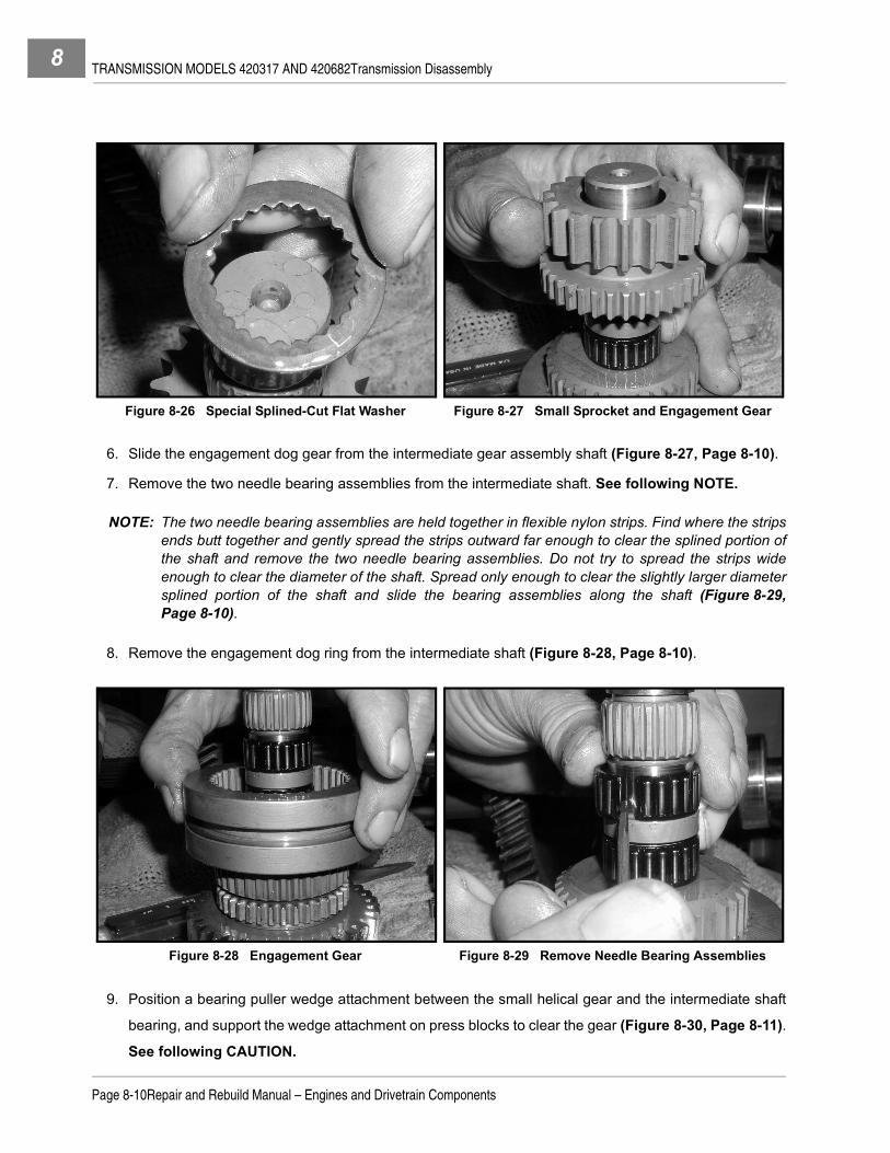
TRANSMISSION MODELS 420317 AND 420682Transmission Disassembly8
6. Slide the engagement dog gear from the intermediate gear assembly shaft (Figure 8-27, Page 8-10).
7. Remove the two needle bearing assemblies from the intermediate shaft. See following NOTE.
NOTE: The two needle bearing assemblies are held together in flexible nylon strips. Find where the stripsends butt together and gently spread the strips outward far enough to clear the splined portion ofthe shaft and remove the two needle bearing assemblies. Do not try to spread the strips wideenough to clear the diameter of the shaft. Spread only enough to clear the slightly larger diametersplined portion of the shaft and slide the bearing assemblies along the shaft (Figure 8-29,Page 8-10).
8. Remove the engagement dog ring from the intermediate shaft (Figure 8-28, Page 8-10).
9. Position a bearing puller wedge attachment between the small helical gear and the intermediate shaft
bearing, and support the wedge attachment on press blocks to clear the gear (Figure 8-30, Page 8-11).
See following CAUTION.
Figure 8-26 Special Splined-Cut Flat Washer Figure 8-27 Small Sprocket and Engagement Gear
Figure 8-28 Engagement Gear Figure 8-29 Remove Needle Bearing Assemblies
Page 8-10Repair and Rebuild Manual – Engines and Drivetrain Components

TRANSMISSION MODELS 420317 AND 420682Transmission Disassembly 8
CAUTION
• Be careful to position the wedge attachment between the bearing and gear and NOT under the
snap ring between the two.
10. Position a bar or socket slightly smaller in diameter than the intermediate shaft and press the bearing
from the helical gear and intermediate shaft (Figure 8-31, Page 8-11).
11. Remove the snap ring and flat washer next to the small helical gear (Figure 8-32, Page 8-11).
12. Slide the small helical and engagement gear assembly from the intermediate shaft and two needle bear-ing assemblies (Figure 8-33, Page 8-11).
13. Slide the two needle bearing assemblies off the intermediate shaft (Figure 8-34, Page 8-12).
Figure 8-30 Position Small Helical Gear and Bearing Figure 8-31 Remove Small Helical Gear Bearing
Figure 8-32 Remove Snap Ring and Flat Washer Figure 8-33 Remove Small Helical and Engagement Gear Assembly from Intermediate Shaft
Repair and Rebuild Manual – Engines and Drivetrain ComponentsPage 8-11

TRANSMISSION MODELS 420317 AND 420682Transmission Disassembly8
OUTPUT SHAFT DISASSEMBLY
1. Position a bearing puller wedge attachment between the large chain sprocket and the output shaft bear-ing and support the wedge attachment on press blocks to clear the gear (Figure 8-35, Page 8-12).
2. Position a bar or socket slightly smaller in diameter than the output shaft and press the bearing from thelarge chain sprocket and shaft.
3. Remove the snap ring and flat washer from the large chain sprocket and output shaft (Figure 8-36,Page 8-12).
4. Remove the splined chain sprocket from the output shaft (Figure 8-37, Page 8-13).
5. Position a bearing puller wedge attachment between the large helical gear and the output shaft bearingand support the wedge attachment on press blocks to clear the gear (Figure 8-38, Page 8-13).
Figure 8-34 Remove Needle Bearing Assemblies
Figure 8-35 Position Puller Between Large Chain Sprocket and Bearing
Figure 8-36 Snap Ring and Washer on Chain Sprocket
Page 8-12Repair and Rebuild Manual – Engines and Drivetrain Components

TRANSMISSION MODELS 420317 AND 420682Transmission Disassembly 8
6. Press the output shaft through the bearing from the large chain sprocket.
7. Remove the snap ring and flat washer from the shaft and large helical gear (Figure 8-39, Page 8-13).
8. Remove the large helical gear from the splined output shaft (Figure 8-40, Page 8-13).
SHIFTER SHAFT REMOVAL
1. Remove the locknut from the D-shaped bellcrank arm (Figure 8-41, Page 8-14).
2. Remove the shifter shaft snap ring (Figure 8-42, Page 8-14).
Figure 8-37 Remove Splined Chain Sprocket Figure 8-38 Position Puller Between Large Helical Gear and Bearing
Figure 8-39 Remove Snap Ring and Flat Washer Figure 8-40 Remove Large Helical Gear
Repair and Rebuild Manual – Engines and Drivetrain ComponentsPage 8-13

TRANSMISSION MODELS 420317 AND 420682Transmission Disassembly8
3. Slide the shifter shaft and fork to the inside of the case and remove the shaft (Figure 8-43, Page 8-14).
4. Use a small bearing puller and remove the shifter shaft seal from the case (Figure 8-44, Page 8-14).
SHIFTER SHAFT INSTALLATION1. Slide a new shifter shaft seal into the case and seat it by tapping on it using a small socket or tube slightly
smaller than the outside diameter of the seal (Figure 8-44, Page 8-14).2. Slide a new shifter shaft and fork from inside the case and through the seal.
3. Install a new snap ring onto the shifter shaft next to the shaft seal (Figure 8-42, Page 8-14).4. Install bell crank arm onto the D-shaped end of the shifter shaft.
5. Install a nylon locknut onto the shifter shaft and tighten nut to 16 ft-lb (22 N·m) (Figure 8-41, Page 8-14).
CASE INSPECTION1. Inspect case for cracks and worn bearing cavities.
2. If any bearing seat has become worn or damaged, both halves will have to be replaced.
Figure 8-41 Bell Crank Arm on Shifter Shaft Figure 8-42 Shifter Shaft Snap Ring
Figure 8-43 Shifter Shaft and Fork Figure 8-44 Shifter Shaft Seal
Page 8-14Repair and Rebuild Manual – Engines and Drivetrain Components

TRANSMISSION MODELS 420317 AND 420682Transmission Disassembly 8
SHAFT SEAL REMOVAL1. Position a case half with shaft seals up.
2. Use a socket or thick wall tube slightly smaller in diameter than the seal and gently drive the seal fromoutside to inside the case to remove each seal (Figure 8-45, Page 8-15). See following NOTE.
NOTE: The case does not have a seal landing area but rather provided with a clean bore.
3. Clean and remove any dirt and debris from the seal area.
SHAFT SEAL INSTALLATION1. Position a case half with shaft seals up.
2. Position seals with lips to the inside of the case and gently drive the seals flush with the outside of thecase using a seal installation tool, socket or thick wall tube slightly smaller in diameter than the seal(Figure 8-46, Page 8-15). See following NOTE.
NOTE: The seals have a light press fit dimension and the bores do not have seal landing areas. Take careto only drive the seals flush with the outside of the case.
OUTPUT SHAFT ASSEMBLY1. Inspect the output shaft for worn splined areas and shaft journals and replace the shaft if necessary.
2. Position the shaft so that the helical gear spline is to the right of the center portion of the shaft. Slide thelarge helical gear onto the output shaft and up against the center hub (Figure 8-47, Page 8-16).
3. Position the opposite end of the output shaft down through the shaft hole in the service fixture with thehelical gear up.
4. Install a flat washer onto the output shaft against the helical gear hub (Figure 8-48, Page 8-16).5. Install a snap ring onto the output shaft and helical gear (Figure 8-49, Page 8-16).
6. Reposition the output shaft with the helical gear shaft end down through the shaft hole in the service fix-ture (Figure 8-50, Page 8-16).
7. Install the large chain sprocket onto the splined portion of the output shaft opposite the helical gear(Figure 8-51, Page 8-16).
Figure 8-45 Remove Shaft Seals from Case Figure 8-46 Install Shaft Seals in Case
Repair and Rebuild Manual – Engines and Drivetrain ComponentsPage 8-15

TRANSMISSION MODELS 420317 AND 420682Transmission Disassembly8
Figure 8-47 Slide Large Helical Gear onto Shaft Figure 8-48 Helical Gear Flat Washer
Figure 8-49 Helical Gear Snap Ring Figure 8-50 Reosition Output Shaft in Fixture
Figure 8-51 Large Chain Sprocket Figure 8-52 Chain Sprocket Flat Washer
Page 8-16Repair and Rebuild Manual – Engines and Drivetrain Components

TRANSMISSION MODELS 420317 AND 420682Transmission Disassembly 8
8. Install the chain sprocket flat washer (Figure 8-52, Page 8-16).
9. Install the chain sprocket snap ring (Figure 8-53, Page 8-17).
10. Install the chain sprocket bearing snap ring (Figure 8-54, Page 8-17).
11. Position the output shaft with the large helical gear splined end down against a metal plate on a pressplaten. Hold the shaft on the center hub and slide a bearing over the large chain sprocket splined endof the shaft and against the chain sprocket bearing race. Slide a tube over the shaft to fit against the innerrace of the bearing (Figure 8-55, Page 8-17).
12. Press the large chain sprocket bearing onto the output shaft (Figure 8-56, Page 8-17). See followingCAUTION.
CAUTION
• Be sure to press only on the inner race of the bearing.• Be careful to press bearing only until it seats snuggly against the shaft snap ring. Excess
pressure could fracture or break the snap ring, or damage the snap ring groove in the shaft.
Figure 8-53 Chain Sprocket Snap Ring Figure 8-54 Large Chain Sprocket Bearing Snap Ring
Figure 8-55 Chain Sprocket End Up On Press Figure 8-56 Chain Sprocket Bearing On Shaft
Repair and Rebuild Manual – Engines and Drivetrain ComponentsPage 8-17

TRANSMISSION MODELS 420317 AND 420682Transmission Disassembly8
13. Position the output shaft with the large chain sprocket splined end down against a metal plate on a pressplaten. Hold the shaft on the center hub and slide a bearing over the helical gear splined end of the shaftand against the helical gear bearing race (Figure 8-57, Page 8-18).
14. Press the large helical gear bearing onto the output shaft (Figure 8-58, Page 8-18).
15. Place a protective cloth over the service fixture.
16. Place the output shaft assembly on the fixture and make sure that the completed assembly is orientedcorrectly (Figure 8-59, Page 8-18).
INTERMEDIATE SHAFT ASSEMBLY1. Inspect the intermediate shaft for worn splined areas and shaft journals. Replace the shaft if necessary.
2. Install bearings on the shaft for the small chain sprocket (Figure 8-61, Page 8-19). See following CAU-TION.
Figure 8-57 Helical Gear End Up On Press Figure 8-58 Helical Gear Bearing On Shaft
Figure 8-59 Completed Output Shaft Assembly Figure 8-60 Inspect Intermediate Shaft
Page 8-18Repair and Rebuild Manual – Engines and Drivetrain Components
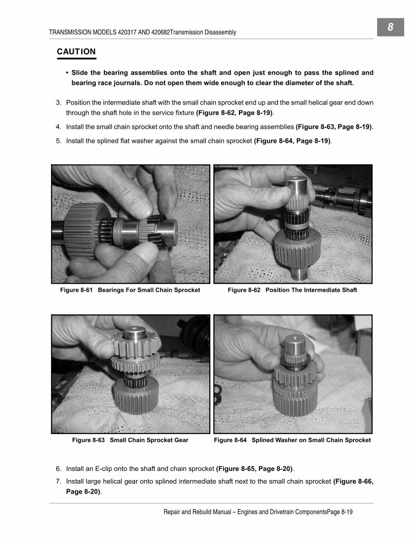
TRANSMISSION MODELS 420317 AND 420682Transmission Disassembly 8
CAUTION
• Slide the bearing assemblies onto the shaft and open just enough to pass the splined andbearing race journals. Do not open them wide enough to clear the diameter of the shaft.
3. Position the intermediate shaft with the small chain sprocket end up and the small helical gear end downthrough the shaft hole in the service fixture (Figure 8-62, Page 8-19).
4. Install the small chain sprocket onto the shaft and needle bearing assemblies (Figure 8-63, Page 8-19).
5. Install the splined flat washer against the small chain sprocket (Figure 8-64, Page 8-19).
6. Install an E-clip onto the shaft and chain sprocket (Figure 8-65, Page 8-20).
7. Install large helical gear onto splined intermediate shaft next to the small chain sprocket (Figure 8-66,Page 8-20).
Figure 8-61 Bearings For Small Chain Sprocket Figure 8-62 Position The Intermediate Shaft
Figure 8-63 Small Chain Sprocket Gear Figure 8-64 Splined Washer on Small Chain Sprocket
Repair and Rebuild Manual – Engines and Drivetrain ComponentsPage 8-19

TRANSMISSION MODELS 420317 AND 420682Transmission Disassembly8
8. Install an E-clip onto the intermediate shaft to secure the large helical gear (Figure 8-67, Page 8-20).
9. Check the orientation of components for proper assembly (Figure 8-68, Page 8-20).
10. Position the intermediate shaft with the small helical gear end up and large helical gear down against theservice fixture, and slide new roller bearing assemblies onto the gear race (Figure 8-69, Page 8-21).
11. Slide the splined engagement gear ring onto the splined intermediate shaft and small chain sprocket(Figure 8-70, Page 8-21).
12. Install the small helical gear onto intermediate shaft (Figure 8-71, Page 8-21).
13. Install the flat washer on helical gear (Figure 8-72, Page 8-21).
14. Install the snap ring onto shaft to secure the small helical gear (Figure 8-73, Page 8-21).
15. Position the large helical gear end of intermediate shaft against a steel plate on a press platen and pressa new bearing onto small helical gear bearing race until the bearing inner race is flush with the end of theintermediate shaft (Figure 8-74, Page 8-21).
Figure 8-65 E-Clip on Small Chain Sprocket Figure 8-66 Large Helical Gear
Figure 8-67 E-Clip on Large Helical Gear Figure 8-68 Assembly Orientation
Page 8-20Repair and Rebuild Manual – Engines and Drivetrain Components
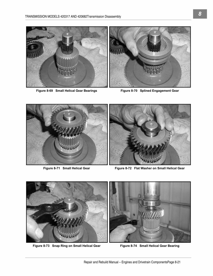
TRANSMISSION MODELS 420317 AND 420682Transmission Disassembly 8
Figure 8-69 Small Helical Gear Bearings Figure 8-70 Splined Engagement Gear
Figure 8-71 Small Helical Gear Figure 8-72 Flat Washer on Small Helical Gear
Figure 8-73 Snap Ring on Small Helical Gear Figure 8-74 Small Helical Gear Bearing
Repair and Rebuild Manual – Engines and Drivetrain ComponentsPage 8-21

TRANSMISSION MODELS 420317 AND 420682Transmission Disassembly8
16. Position the small helical gear end of intermediate shaft against a steel plate on a press platen(Figure 8-75, Page 8-22).
17. Press a new bearing onto large helical gear bearing race until the bearing inner race is flush with the endof the intermediate shaft.
INTERMEDIATE AND OUTPUT SHAFT ASSEMBLY1. Position the output shaft assembly on the service fixture with the large chain sprocket and bearing up and
the helical gear end of the output shaft down through the shaft hole in the service fixture (Figure 8-76,Page 8-22).
2. Slip the chain over the large chain sprocket on the output shaft (Figure 8-77, Page 8-22).
3. Place the small helical gear end of the intermediate shaft down into the chain and lift up on the chain,placing it on the small sprocket and slide the intermediate shaft assembly next to the output shaft.
4. Begin working the chain onto the large chain sprocket, lifting it up as it’s being attached to the sprocket.See following NOTE.
Figure 8-75 Large Helical Gear Bearing Figure 8-76 Output Shaft Assembly on Fixture
Figure 8-77 Shafts and Gears Assembly Figure 8-78 Attach Chain
Page 8-22Repair and Rebuild Manual – Engines and Drivetrain Components

TRANSMISSION MODELS 420317 AND 420682Transmission Assembly 8
NOTE: It may be necessary to move the gears and shafts around a little to provide enough slack for thechain to be attached.
TRANSMISSION ASSEMBLY
See General Warning on page 1-1.
CAUTION
• Make sure that the inside of both halves of the transmission case are clean and free of old oil,dirt, old gasket material and debris.
1. Position case (back half) onto the service fixture with the output shaft bearing port directly over the shafthole in the fixture and the fixture positioned with the shaft hole to the left on the work bench. Clamp orbolt the fixture to a clean working surface or bench top (Figure 8-79, Page 8-23). See following NOTE.
NOTE: Positioning the through hole in the fixture to the left allows easy access to the shifter shaft andrelated components during assembly.
2. Install the ground speed governor shaft yoke bracket and tighten screws and lock washers to 15 in-lb (1.7N·m) (Figure 8-80, Page 8-24).
3. Install the intermediate and output shaft and gear assembly into the back case, aligning the front outputshaft down through the case and seal and through the service fixture (Figure 8-81, Page 8-24). See fol-lowing CAUTION and NOTE.
CAUTION
• Be careful when passing the front output shaft through the shaft seal to not damage ordislodge the seal from the case. See following NOTE.
NOTE: Allow the front output shaft and intermediate shaft bearings to rest at the edge of the case cavities.Do not tap on the shafts to seat the bearings at this stage.
Figure 8-79 Position Back Half on Fixture
Repair and Rebuild Manual – Engines and Drivetrain ComponentsPage 8-23

TRANSMISSION MODELS 420317 AND 420682Transmission Assembly8
4. Gently lift the engagement ring up as far as it will go with gears meshed. Hold it in position and slide theengagement fork into the groove in the engagement ring gear, and allow the engagement fork shaft tofit down into the case cavity provided.
5. Position the gear shifter bell crank arm down and slightly to the left, with the shifter arm fork up andslightly to the right (Figure 8-82, Page 8-24).
6. Hold the engagement gear fork into place, lifting it and holding the engagement gear up, and leaning itslightly to the left, away from the shifter arm fork (Figure 8-83, Page 8-24).
7. Hold the engagement gear fork shaft up with one hand and at the same time move the fork shaft and pinto the right. Turn the shifter bell crank arm so that the shifter arm fork interlaces with the engagement forkshaft pin (Figure 8-84, Page 8-25).
8. Allow the engagement fork and gear to drop down to its lowest position, causing the shifter arm bell crankto rotate upward and rest parallel with the case edge (Figure 8-85, Page 8-25).
9. Tap gently on the top of both shafts with a rubber mallet until the bearings are seated in the case cavities.
Figure 8-80 Governor Shaft Yoke Bracket Figure 8-81 Intermediate and Output Shaft and Gears
Figure 8-82 Gear Shifter Fork and Engagement Fork Figure 8-83 Engagement Gear and Fork Held Upward
Page 8-24Repair and Rebuild Manual – Engines and Drivetrain Components
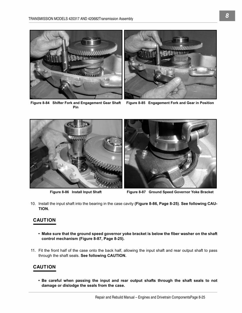
TRANSMISSION MODELS 420317 AND 420682Transmission Assembly 8
10. Install the input shaft into the bearing in the case cavity (Figure 8-86, Page 8-25). See following CAU-TION.
CAUTION
• Make sure that the ground speed governor yoke bracket is below the fiber washer on the shaftcontrol mechanism (Figure 8-87, Page 8-25).
11. Fit the front half of the case onto the back half, allowing the input shaft and rear output shaft to passthrough the shaft seals. See following CAUTION.
CAUTION
• Be careful when passing the input and rear output shafts through the shaft seals to notdamage or dislodge the seals from the case.
Figure 8-84 Shifter Fork and Engagement Gear Shaft Pin
Figure 8-85 Engagement Fork and Gear in Position
Figure 8-86 Install Input Shaft Figure 8-87 Ground Speed Governor Yoke Bracket
Repair and Rebuild Manual – Engines and Drivetrain ComponentsPage 8-25

TRANSMISSION MODELS 420317 AND 420682Transmission Assembly8
12. Install the neutral limit switch and detent barrel assembly and tighten to 21 ft-lb (28 N·m) (Figure 8-88,Page 8-26).
13. Apply a 1/8-inch (2 mm) wide coat of Three Bond sealant or Loctite 5699 Gasket Eliminator to the bottomhalf of the case. See following CAUTION.
CAUTION
• Apply adjacent to the inside edge of the case only.
14. Gently press on the case and allow the bearings to begin seating in the case. Gently tap on the case atpositions close to each shaft area to help seat the bearings and sealant (Figure 8-89, Page 8-26).
15. Install the case bolts and tighten, in a criss-cross pattern as shown, to 25 ft-lb (34 N·m) (Figure 8-90,Page 8-26).
16. Install the drain plug and washer and tighten to 8 ft-lb (11 N·m).
Figure 8-88 Neutral Limit Switch Figure 8-89 Transmission Case Assembly
Figure 8-90 Case Bolts – Tightening Sequence
12
36
9 7
11
5
108
4
Page 8-26Repair and Rebuild Manual – Engines and Drivetrain Components

TRANSMISSION MODELS 420317 AND 420682Transmission Installation 8
17. Remove the fill and level plugs and fill the case through the top fill plug with 20 ounces (600 mL) of Mobil424, Exxon Hydraul 560, or Esso Hydraul 56 lubricant. See following NOTE.
NOTE: When the proper amount of lubricant has been added, the lubricant should be level with the levelplug on the side of the case.
18. Install the level plug using a small amount of Loctite 545 thread sealant on the threads and tighten to 20ft-lb (27 N·m).
19. Install the fill plug on the top of the case using a small amount of Loctite 545 thread sealant on the threadsand tighten to 20 ft-lb (27 N·m).
TRANSMISSION INSTALLATION
See Transmission Installation, Section 14, in the appropriate maintenance and service manual.
Repair and Rebuild Manual – Engines and Drivetrain ComponentsPage 8-27

8

9
SECTION 9 – FRONT DIFFERENTIAL MODELS 6203-01-139-S AND 6203-01-189-Sý DANGER
• See General Warning on page 1-1.
ý WARNING
• See General Warning on page 1-1.
GENERAL INFORMATION
The front differential provides power to the front left and right half shafts which in turn drive the front left andright wheels. It is designed with an electromagnet assembly located in the right front output cover plate. Theelectromagnet is connected to the vehicle’s electrical system and must be electrically energized to work prop-erly. For electrical testing and system diagrams refer to Sections 11a, 11b, 12a, and 12b in the appropriatemaintenance and service manual.
Information in this Section 9 provides procedures to disassemble, replace parts, and assemble the front dif-ferential. It does not include any electrical testing or service information other than the removal and replace-ment of appropriate electromagnet components.
The front differential has a left output splined hub and a right output splined hub. The left output side has theserial and model number label (Figure 9-1, Page 9-1). The right output side is equipped with the electromag-net coil, coil connector plug, and backlash adjustment screw (Figure 9-2, Page 9-1).
AXLE HALF SHAFT REMOVAL
See Half Shaft Removal, Section 14, in the appropriate maintenance and service manual.
Figure 9-1 Front Differential – Left Front Output Figure 9-2 Front Differential – Right Front Output
Repair and Rebuild Manual – Engines and Drivetrain ComponentsPage 9-1

FRONT DIFFERENTIAL MODELS 6203-01-139-S AND 6203-01-189-SFront Differential Removal9
FRONT DIFFERENTIAL REMOVAL
See Front Differential Removal, Section 14, in the appropriate maintenance and service manual.
Figure 9-3 Front Differential
12
3
4 5
6
7
8
9
1011
1213
1415
16
17
18
19
21
22
23
24
25
26
27
28
29
3031
32
33
34
35
36
37
38
39
40
41
20
Page 9-2Repair and Rebuild Manual – Engines and Drivetrain Components

FRONT DIFFERENTIAL MODELS 6203-01-139-S AND 6203-01-189-SFront Differential Coil And Output Cover 9
TOOLS REQUIRED FOR THIS SECTION
FRONT DIFFERENTIAL COIL AND OUTPUT COVER
See General Warning on page 1-1.
COIL AND OUTPUT COVER REMOVAL
NOTE: If the electrical coil wires are damaged beyond repair, or coil fails to operate properly, the entireoutput cover plate must be replaced. The electrical coil, as a component, is not replaceable.
1. Position the front differential case over a pan or container suitable for draining oil and remove the drainplug from the bottom of the case. Drain the oil from the case and dispose of the oil properly (Figure 9-4,Page 9-3).
2. Position differential case on a clean solid surface with the coil and output cover up.
3. Remove bolts from the output cover (Figure 9-5, Page 9-3).
Hydraulic press Plastic or rubber mallet 11 mm socket, 3/8 in. driveBearing puller wedge attachment(P/N CCI 1012812) Axle seal tool (P/N CCI 1014162) 13 mm Socket, 3/8 in. drive
Small ball peen hammer (10 oz.) Ratchet wrench, 3/8 in. drive Small flat blade screwdriverOil drain pan or tray Torque wrench, 3/8 in. drive Medium flat blade screwdriver
Figure 9-4 Remove Drain Plug and Drain Oil Figure 9-5 Remove Coil and Output Cover
Repair and Rebuild Manual – Engines and Drivetrain ComponentsPage 9-3

FRONT DIFFERENTIAL MODELS 6203-01-139-S AND 6203-01-189-SFront Differential Coil And Output Cover9
4. Gently tap on the output cover flange with a plastic or rubber mallet to loosen the cover (Figure 9-6,Page 9-4)
5. Remove output cover, coil, and male splined hub (Figure 9-7, Page 9-4).
Coil and Output Cover Disassembly
1. Position the output cover on a clean solid surface with the splined hub up (Figure 9-8, Page 9-4).
2. Remove the thrust plate from the cover.
3. Remove the retaining ring from around the inside edge of the cover flange (Figure 9-9, Page 9-4).
4. Remove armature plate shim (Figure 9-10, Page 9-5).
5. Remove armature plate (Figure 9-11, Page 9-5).
Figure 9-6 Coil Cover Plate Flange Figure 9-7 Coil Cover Plate and Male Hub
Figure 9-8 Thrust Plate Figure 9-9 Cover Retaining Ring
Page 9-4Repair and Rebuild Manual – Engines and Drivetrain Components

FRONT DIFFERENTIAL MODELS 6203-01-139-S AND 6203-01-189-SFront Differential Coil And Output Cover 9
6. Hold the output cover vertical by holding the splined hub (Figure 9-12, Page 9-5).
7. Use a small diameter wooden or rubber mallet, or wooden or fiberglass tool handle, and gently tap thehub and bearing from the cover (Figure 9-13, Page 9-5).
Coil and Output Cover Assembly1. Position a new coil and output cover on a clean solid surface and install the male hub and bearing into
the bearing cavity by gently tapping the dowel pin end of the hub (Figure 9-14, Page 9-6).
2. Position armature plate around hub and bearing (Figure 9-11, Page 9-5). See following NOTE.
NOTE: The seven tabs on the armature plate fit into the ring gear hub when assembled. Aligning the ringgear tab slots with the pinion gear shaft helps to establish a match location between the ring gearhub and the armature plate tabs.
3. Install the armature plate shim (Figure 9-10, Page 9-5).
4. Install the armature retaining ring (Figure 9-9, Page 9-4).
Figure 9-10 Armature Plate Shim Figure 9-11 Armature Plate
Figure 9-12 Right Splined Male Hub and Bearing Figure 9-13 Remove Hub and Bearing From Cover
Repair and Rebuild Manual – Engines and Drivetrain ComponentsPage 9-5

FRONT DIFFERENTIAL MODELS 6203-01-139-S AND 6203-01-189-SFront Differential Coil And Output Cover9
5. Install the thrust plate on the output cover (Figure 9-15, Page 9-6). See following NOTE.
NOTE: Apply a small amount of clean gear grease under the thrust plate before slipping it onto the thrustbutton. The grease will act as an adhesive and will help hold the plate in place when the plate isturned upside down for installation.
6. Install the needle sized roller thrust bearing onto the male pin of the hub (Figure 9-16, Page 9-7). Seefollowing NOTE.
NOTE: Apply a small amount of clean gear grease under the thrust bearing before slipping it onto the hubpin. The grease will act as an adhesive and will help hold the bearing in place when the plate isturned upside down for installation.
COIL AND OUTPUT COVER INSTALLATION
1. Position the ring gear and housing assembly on a clean solid surface with the ring gear hub up.
2. Use the pinion gear shaft and turn the gear so that one of the tab slots in the ring gear hub and bearingcage assembly is in line with the pinion gear shaft (Figure 9-17, Page 9-7).
3. Position the armature plate on the hub cover so that one of the tabs will align with the pinion shaft andcorresponding slot in the ring gear hub bearing and cage assembly. See following NOTE.
NOTE: Make sure that the large rubber O-ring gasket is on the cover flange.
4. Gently place the coil and output cover plate, with the armature tabs seating down into the tab slots in thering gear bearing and cage assembly, down onto the case and tighten the case bolts in a criss-cross pat-tern to 17 ft-lb (23 N·m).
5. Adjust the backlash set screw. See Backlash Adjustment on page 9-7.
Figure 9-14 Output Hub and Bearing Figure 9-15 Install Thrust Plate
Page 9-6Repair and Rebuild Manual – Engines and Drivetrain Components

FRONT DIFFERENTIAL MODELS 6203-01-139-S AND 6203-01-189-SFront Differential Coil And Output Cover 9
Backlash Adjustment
1. Locate the backlash adjustment set screw on the right front, coil side, of the differential (Figure 9-19,Page 9-7).
2. Use a 3/32-inch Allen wrench (5/32-inch starting 2007 model year) and turn the screw clockwise until itstops (do not apply torque).
NOTE: When the screw stops, the splined shaft of the pinion gear should not be movable by hand in eitherdirection.
3. Turn the Allen wrench and set screw counterclockwise slowly while turning the pinion gear shaft clock-wise. Continue this process until the pinion gear shaft can rotate four complete turns freely and withoutany tight spots.
NOTE: The set screw should only have to be turned 1/4 to 1/2 of a full turn from its stop position to achievethe proper backlash set.
Figure 9-16 Install Roller Thrust Bearing Figure 9-17 Align Armature Plate Tabs and Ring Gear Bearing Cage Slots
Figure 9-18 Install Cover and Torque Bolts Figure 9-19 Backlash Adjustment Set Screw
Align seven tabs with slotsas shown for properassembly.
Backlash AdjustmentScrew
Repair and Rebuild Manual – Engines and Drivetrain ComponentsPage 9-7

FRONT DIFFERENTIAL MODELS 6203-01-139-S AND 6203-01-189-SFront Differential9
FRONT DIFFERENTIAL
See General Warning on page 1-1.
FRONT DIFFERENTIAL DISASSEMBLY1. Position the front differential case over a pan or container suitable for draining oil and remove the drain
plug from the bottom of the case. Drain the oil from the case and dispose of the oil properly (Figure 9-4,Page 9-3).
2. Position differential case on a clean solid surface with the coil and output cover up.
3. Remove bolts from the output cover (Figure 9-5, Page 9-3).
4. Gently tap on the output cover flange with a plastic or rubber mallet to loosen the cover (Figure 9-6,Page 9-4)
5. Remove output cover, coil, and male splined hub (Figure 9-7, Page 9-4).
6. Remove ring gear with roll cage and roller bearing assembly (Figure 9-20, Page 9-8).
7. Remove the needle sized roller thrust bearing (Figure 9-21, Page 9-8).
Figure 9-20 Ring Gear with Roller Bearings Figure 9-21 Thrust Bearing on Output Hub
Figure 9-22 Remove Gearcase Hub and Bearing Figure 9-23 Gearcase Output Hub Seal
Page 9-8Repair and Rebuild Manual – Engines and Drivetrain Components
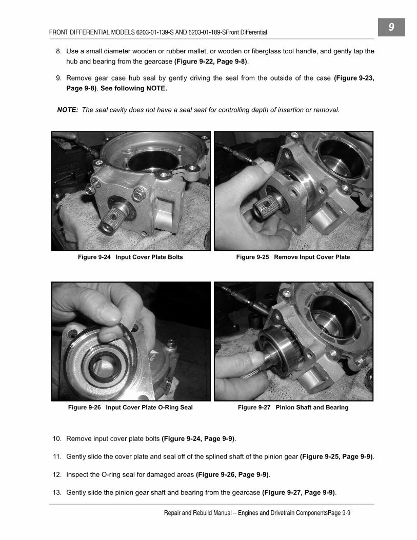
FRONT DIFFERENTIAL MODELS 6203-01-139-S AND 6203-01-189-SFront Differential 9
8. Use a small diameter wooden or rubber mallet, or wooden or fiberglass tool handle, and gently tap thehub and bearing from the gearcase (Figure 9-22, Page 9-8).
9. Remove gear case hub seal by gently driving the seal from the outside of the case (Figure 9-23,Page 9-8). See following NOTE.
NOTE: The seal cavity does not have a seal seat for controlling depth of insertion or removal.
10. Remove input cover plate bolts (Figure 9-24, Page 9-9).
11. Gently slide the cover plate and seal off of the splined shaft of the pinion gear (Figure 9-25, Page 9-9).
12. Inspect the O-ring seal for damaged areas (Figure 9-26, Page 9-9).
13. Gently slide the pinion gear shaft and bearing from the gearcase (Figure 9-27, Page 9-9).
Figure 9-24 Input Cover Plate Bolts Figure 9-25 Remove Input Cover Plate
Figure 9-26 Input Cover Plate O-Ring Seal Figure 9-27 Pinion Shaft and Bearing
Repair and Rebuild Manual – Engines and Drivetrain ComponentsPage 9-9

FRONT DIFFERENTIAL MODELS 6203-01-139-S AND 6203-01-189-SFront Differential9
14. Hold the pinion gear and shaft and gently turn the outside bearing race. The bearing should roll easilywith no rough or flat spots and no excess play. Replace with a new bearing if necessary (Figure 9-31,Page 9-11). See following NOTE.
NOTE: To replace the pinion gear bearing, press the old bearing off, using a hydraulic press, and press anew bearing onto the shaft.
15. Inspect the pinion shaft seal in the cover plate for damaged or worn areas that could be providing for oilleaks (Figure 9-28, Page 9-10). See following NOTE.
NOTE: If damaged, worn or leaking lubrication oil, replace the seal.
Input Shaft Seal Removal1. Place the input cover plate and seal between jaws of a heavy duty vise (Figure 9-28, Page 9-10). See
following NOTE.
NOTE: Make sure the jaws of the vise do not rest against or damage the O-ring shoulder on the back of theinput cover plate.
2. Push the seal out of the cover plate using a seal installation tool or large socket slightly smaller in diam-eter than the seal. Press the seal out from the outside of the cover plate. See following NOTE.
NOTE: There is no seal seat in the cover plate.
Input Shaft Seal Installation1. Position a new three-lip seal on the cover plate (Figure 9-29, Page 9-10).2. Press a new seal into the input cover plate, using a seal installation tool, until the surface of the seal is
flush with the input cover plate (Figure 9-30, Page 9-11).
Figure 9-28 Input Cover Plate and Shaft Seal Figure 9-29 Position New Seal on Cover Plate
Page 9-10Repair and Rebuild Manual – Engines and Drivetrain Components

FRONT DIFFERENTIAL MODELS 6203-01-139-S AND 6203-01-189-SFront Differential 9
3. Inspect the pinion gear and splined portion of the shaft. If the gear is worn, damaged, or the splined por-tion is worn or damaged, replace the pinion and shaft with a new one. See following NOTE.
NOTE: If the pinion gear bearing is removed for any reason, it must be replaced with a new bearing.
4. Inspect the pinion gear shaft bushing inside the gearcase (Figure 9-32, Page 9-11). See followingNOTE.
NOTE: If the pinion shaft bushing is worn it will require a new gearcase, which is provided with a new bush-ing. The bushing is not available as a replacement component.
Clutch and Ring Gear Disassembly1. Position the ring gear and clutch cage with roller bearings on a clean solid surface (Figure 9-33,
Page 9-12).2. Gently raise the clutch cage and the first level of roller bearings to a height where the roller bearings
begin to release from the cage (Figure 9-34, Page 9-12). See following NOTE.
NOTE: The clutch cage has two levels of roller bearings, with seven rollers in each layer. They are held inplace against the inside of the ring gear hub with spring clips.
Figure 9-30 Install New Input Shaft Seal
Figure 9-31 Inspect Pinion Gear Bearing Figure 9-32 Inspect Pinion Gear Shaft Bushing
Repair and Rebuild Manual – Engines and Drivetrain ComponentsPage 9-11

FRONT DIFFERENTIAL MODELS 6203-01-139-S AND 6203-01-189-SFront Differential9
3. Remove the first level of roller bearings from the clutch cage (Figure 9-35, Page 9-12).4. Gently raise the clutch cage and bring the second level of roller bearings to a height where the roller bear-
ings begin to release from the cage (Figure 9-36, Page 9-12).5. Lift the clutch cage from the inside of the ring gear hub. See following NOTE.
NOTE: Observe how the clutch cage is positioned into the ring gear hub.
6. Remove the fourteen spring clips from the clutch cage. See following NOTE.
NOTE: Inspect each spring for broken pieces. The springs are fabricated from spring steel material andwhen damaged will fracture and usually break apart. Look for fragments along the clutch cage andinside of the ring gear hub.
7. Inspect the clutch cage for cracked and broken segments.
Figure 9-33 Ring Gear and Clutch Cage Figure 9-34 Clutch Cage and Roller Bearings
Figure 9-35 Remove First Level of Roller Bearings Figure 9-36 Second Level of Roller Bearing
Page 9-12Repair and Rebuild Manual – Engines and Drivetrain Components

FRONT DIFFERENTIAL MODELS 6203-01-139-S AND 6203-01-189-SFront Differential 9
Clutch and Ring Gear Assembly
CAUTION
• If the clutch bearing cage is damaged or any segments broken, the cage must be replaced.Use all new roller bearings when replacing the clutch cage.
• If any roller bearings need replacing, replace the entire set of fourteen bearings.
• If the ring gear or inside walls of the hub are damaged or badly worn, the ring gear and hubmust be replaced.
• If any of the spring clips are damaged or broken, replace the entire set of fourteen clips.
1. Position the ring gear with the gear down against a clean solid surface.
2. Position a clutch cage and roller bearings close to the ring gear and hub (Figure 9-37, Page 9-13).
3. Slide a clutch cage into the ring gear hub deep enough to allow insertion of roller bearings into the spring
clips and hold them into place (Figure 9-38, Page 9-13).
CAUTION
• Make sure the seven ridges in the ring gear hub align with the seven clutch cage tab slots.
4. Assemble the first level of roller bearings into the clutch cage and ring gear hub and slide the clutch cage
down to the second (or top) bearing level (Figure 9-39, Page 9-14).
5. Assemble the second (or top) level of roller bearings into the clutch cage (Figure 9-40, Page 9-14).
6. Complete the assembly of clutch and ring gear by pushing the clutch cage and roller bearings down so
the clutch is flush with the ring gear hub (Figure 9-41, Page 9-14).
Figure 9-37 Ring Gear Hub, Clutch and Bearings Figure 9-38 Insert Clutch and Bearings
Repair and Rebuild Manual – Engines and Drivetrain ComponentsPage 9-13

FRONT DIFFERENTIAL MODELS 6203-01-139-S AND 6203-01-189-SFront Differential9
FRONT DIFFERENTIAL ASSEMBLY
CAUTION
• If the inside lining of the gearcase wall is damaged, the gearcase must be replaced. The wall
lining, as a component, is not replaceable.
1. Position the gearcase on a clean solid surface with the output seal cavity up. See following NOTE.
NOTE: Clean and remove all debris and old oil in bearing cavities. Apply a light coat of gear oil to the cavity
area to aid in seal installation.
Figure 9-39 Assemble First Level of Bearings Figure 9-40 Assemble Second Level of Bearings
Figure 9-41 Position Clutch Into Ring Gear Hub
Page 9-14Repair and Rebuild Manual – Engines and Drivetrain Components

FRONT DIFFERENTIAL MODELS 6203-01-139-S AND 6203-01-189-SFront Differential 9
2. Install a seal into the gearcase cavity using a seal installation tool or large socket, slightly smaller thanthe seal body diameter (Figure 9-42, Page 9-15).
3. Gently tap the seal body down until the face of the seal is 1/8-inch (3 mm) below the cavity surface.
4. Position the gearcase on a clean solid surface with the output seal down (Figure 9-43, Page 9-15). Seefollowing NOTE.
NOTE: Clean and remove all debris and old oil in gearcase cavities and inside surfaces.
5. Install a female output hub and bearing into the gearcase bearing cavity and gently tap the hub until thebearing seats in the gearcase (Figure 9-44, Page 9-15).
6. Install the ring gear hub with clutch and roller bearing assembly into the gearcase and down around thefemale output hub (Figure 9-45, Page 9-15).
7. Push the clutch cage and bearing assembly down to be flush with the top surface of the ring gear hub(Figure 9-46, Page 9-16).
Figure 9-42 Install Output Seal Figure 9-43 Position Gearcase with Seal Down
Figure 9-44 Install Output Hub and Bearing Figure 9-45 Install Ring Gear and Hub
Repair and Rebuild Manual – Engines and Drivetrain ComponentsPage 9-15

FRONT DIFFERENTIAL MODELS 6203-01-139-S AND 6203-01-189-SFront Differential9
8. Use the pinion gear shaft and turn the gear so that one of the tab slots in the ring gear hub and bearingcage assembly is in line with the pinion gear shaft (Figure 9-17, Page 9-7). See following NOTE.
NOTE: The seven tabs on the armature plate fit into these ring gear hub tab slots when assembled. Align-ing the ring gear tab slots with the pinion gear shaft helps to establish a match location between thering gear hub and the armature plate tabs.
9. Prepare a coil and output cover assembly for installation on the gearcase. See Coil and Output CoverAssembly on page 9-5.
10. Position the armature plate on the hub cover so that one of the tabs will align with the pinion shaft andcorresponding slot in the ring gear hub bearing and cage assembly. See following NOTE.
NOTE: Make sure that the large rubber O-ring gasket is on the cover flange.
11. Gently place the cover plate down onto the case, with the seven armature tabs seating down into the tabslots in the ring gear bearing and cage assembly (Figure 9-47, Page 9-16).
NOTE: Clean and remove all debris and old oil in bearing cavity. Apply a light coat of gear oil to the cavityarea to aid in bearing installation.
12. Install input pinion gear, shaft and bearing. Gently tap on the input shaft with a rubber or wooden malletto seat the bearing (Figure 9-48, Page 9-17). See following NOTE.
NOTE: Carefully align the input pinion gear with the ring gear before seating the bearing.
13. Seat the pinion gear bearing into the gearcase cavity (Figure 9-49, Page 9-17). See following NOTE.
NOTE: The bearing outside race should slide into the gearcase cavity without having a press fit.
Figure 9-46 Ring Gear Assembled Into Gearcase Figure 9-47 Coil Side Cover on Gearcase
Page 9-16Repair and Rebuild Manual – Engines and Drivetrain Components

FRONT DIFFERENTIAL MODELS 6203-01-139-S AND 6203-01-189-SFront Differential 9
14. Install input cover plate and three-lip seal on input shaft (Figure 9-51, Page 9-18).
NOTE: Make sure that the O-ring is on the input cover plate (Figure 9-52, Page 9-18).
15. Install the input cover plate and output cover plate bolts and tighten, in a criss-cross pattern as shown,to 17 ft-lb (23 N·m) (Figure 9-50, Page 9-17).
16. Adjust the backlash set screw. See Backlash Adjustment on page 9-7.
17. Remove the oil fill plug and add 5 ounces (150 ml) of Mobil 424, Exxon Hydraul 560, or Esso Hydraul 56lubricant. See following CAUTION.
Figure 9-48 Input Pinion Gear, Shaft and Bearing Figure 9-49 Seat Input Bearing
Figure 9-50 Output Cover Plate – Tightening Sequence
1
2
3
6
7
5
4
Repair and Rebuild Manual – Engines and Drivetrain ComponentsPage 9-17

FRONT DIFFERENTIAL MODELS 6203-01-139-S AND 6203-01-189-SFront Differential Installation9
CAUTION
• Do not use any other brand or type of oil.
18. Install the oil fill plug and tighten the plug to 10 ft-lb (13 N·m).
FRONT DIFFERENTIAL INSTALLATION
See Front Differential Installation, Section 14, in the appropriate maintenance and service manual.
AXLE HALF SHAFT INSTALLATION
See Half Shaft Installation, Section 14, in the appropriate maintenance and service manual.
Figure 9-51 Input Cover Plate and Three-Lip Seal Figure 9-52 O-Ring on Input Cover Plate
Page 9-18Repair and Rebuild Manual – Engines and Drivetrain Components

10
SECTION 10 – REAR DIFFERENTIAL MODELS 420366 AND 420851ý DANGER
• See General Warning on page 1-1.
ý WARNING
• See General Warning on page 1-1.
GENERAL INFORMATION
The 420366 and 420851 rear differential models are heavy-duty, fully-synchronized gear-driven differentials.They are self-contained.
Model and Serial Number
The model and serial number are located on the top rear portion of the housing (Figure 10-1, Page 10-1).The procedures in this manual can be used for model 420366 and model 420851.
Tools Required For This Section
Figure 10-1 Rear Differential Figure 10-2 Lubricant Level
Hydraulic press Plastic or rubber mallet External snap ring pliers (.047 in. tip), 45°
13 mm combination wrench Differential Assembly Tool/Fixture(CCI P/N 102723001)
Bearing puller wedge attachment(CCI P/N 1012812)
15 mm combination wrench ThreeBond® #1215 gasket compound Medium flat blade screwdriver
16 mm combination wrench Oil drain pan or tray
Repair and Rebuild Manual – Engines and Drivetrain ComponentsPage 10-1

REAR DIFFERENTIAL MODELS 420366 AND 420851Axle Shafts and Differential Removal10
AXLE SHAFTS AND DIFFERENTIAL REMOVAL
See Rear Differential and Axles in the appropriate maintenance and service manual.
REAR DIFFERENTIAL DISASSEMBLY
See General Warning on page 1-1.1. Remove the bottom drain plug (4) and plug washer (5) and drain the lubrication oil from the differential
housing (Figure 10-4, Page 10-3).
2. Clean the outside surfaces of the differential housing.
3. Gently scrape any sealant or gasket material from the housing surfaces where the flanged portion of theaxles bolted to the differential.
4. Move the differential assembly to a clean bench area.
NOTE: It helps to mark driver side and passenger side on the differential housing. Be sure to correctlyidentify each side. References will be made to those designations during disassembly and assem-bly. Use a felt tip marker on the housing where the axle flanges bolt for those markings.
Figure 10-3 Axle Shafts And Differential Assembly
1
1
TYPICAL 6 PLACES
TYPICAL 6 PLACES
Driver Side
Passenger Side
Page 10-2Repair and Rebuild Manual – Engines and Drivetrain Components

REAR DIFFERENTIAL MODELS 420366 AND 420851Rear Differential Disassembly 10
5. Remove the nine hex flanged-head bolts (2) from the housing (Figure 10-4, Page 10-3).
6. Use two flat wrenches or flat metal bars and gently pry the top portion of the housing away from the bot-tom portion (Figure 10-5, Page 10-4). See following CAUTION.
CAUTION
• To prevent damage to the mating seal surfaces of the case, use care when separating thehalves.
Figure 10-4 Differential Assembly
19
3
15
14
6
5
4
11
8
9
10
12
1
20
21
7
16
17
18
1
TYPICAL 8 PLACES
TYPICAL 2 PLACES
TYPICAL 2 PLACES
2
TYPICAL 9 PLACES
13
Repair and Rebuild Manual – Engines and Drivetrain ComponentsPage 10-3
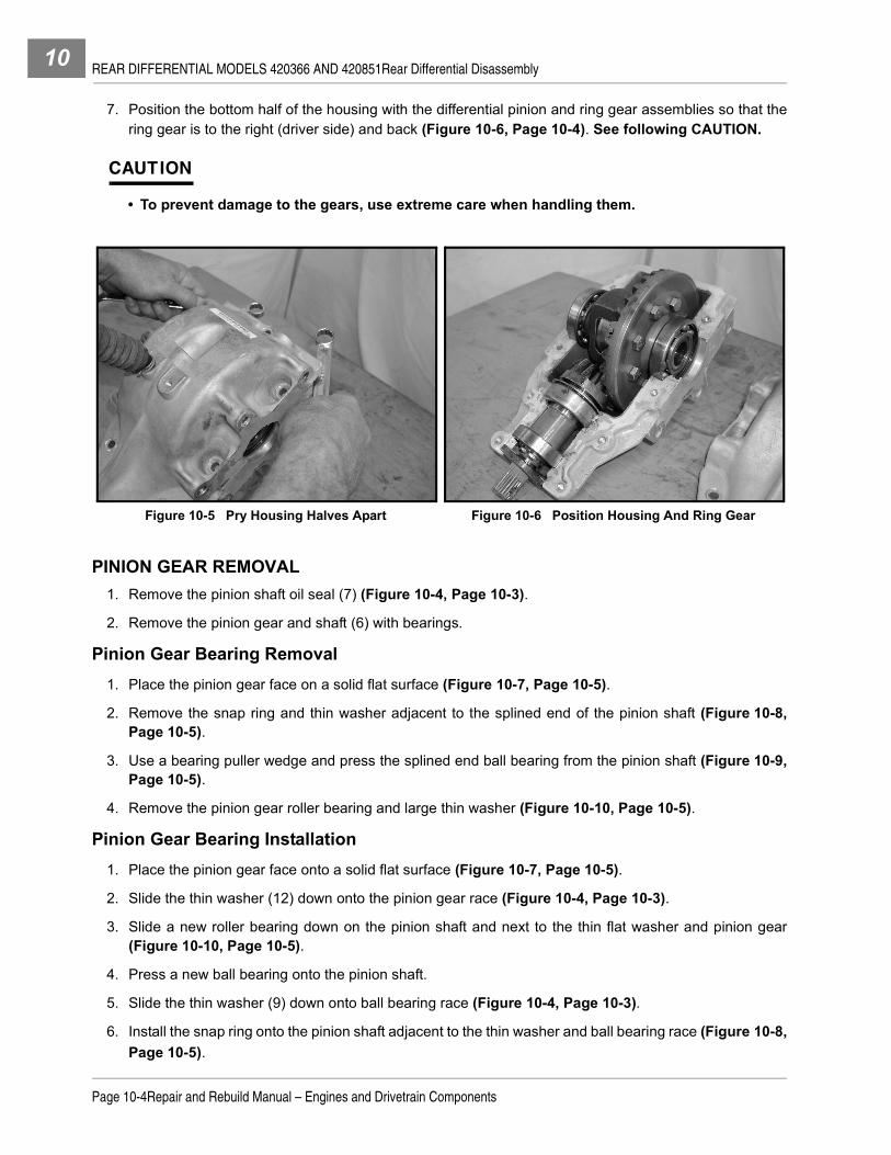
REAR DIFFERENTIAL MODELS 420366 AND 420851Rear Differential Disassembly10
7. Position the bottom half of the housing with the differential pinion and ring gear assemblies so that thering gear is to the right (driver side) and back (Figure 10-6, Page 10-4). See following CAUTION.
CAUTION
• To prevent damage to the gears, use extreme care when handling them.
PINION GEAR REMOVAL1. Remove the pinion shaft oil seal (7) (Figure 10-4, Page 10-3).
2. Remove the pinion gear and shaft (6) with bearings.
Pinion Gear Bearing Removal1. Place the pinion gear face on a solid flat surface (Figure 10-7, Page 10-5).
2. Remove the snap ring and thin washer adjacent to the splined end of the pinion shaft (Figure 10-8,Page 10-5).
3. Use a bearing puller wedge and press the splined end ball bearing from the pinion shaft (Figure 10-9,Page 10-5).
4. Remove the pinion gear roller bearing and large thin washer (Figure 10-10, Page 10-5).
Pinion Gear Bearing Installation1. Place the pinion gear face onto a solid flat surface (Figure 10-7, Page 10-5).
2. Slide the thin washer (12) down onto the pinion gear race (Figure 10-4, Page 10-3).
3. Slide a new roller bearing down on the pinion shaft and next to the thin flat washer and pinion gear(Figure 10-10, Page 10-5).
4. Press a new ball bearing onto the pinion shaft.
5. Slide the thin washer (9) down onto ball bearing race (Figure 10-4, Page 10-3).
6. Install the snap ring onto the pinion shaft adjacent to the thin washer and ball bearing race (Figure 10-8,Page 10-5).
Figure 10-5 Pry Housing Halves Apart Figure 10-6 Position Housing And Ring Gear
Page 10-4Repair and Rebuild Manual – Engines and Drivetrain Components

REAR DIFFERENTIAL MODELS 420366 AND 420851Rear Differential Disassembly 10
Figure 10-7 Pinion Gear Shaft Assembly
Figure 10-8 Snap Ring On Pinion Gear Shaft Figure 10-9 Press Off Splined End Roller Bearing
Figure 10-10 Pinion End Roller Bearing
Repair and Rebuild Manual – Engines and Drivetrain ComponentsPage 10-5

REAR DIFFERENTIAL MODELS 420366 AND 420851Rear Differential Disassembly10
RING GEAR REMOVAL1. Remove the two axle shaft oil seals (14) from the differential housing (Figure 10-4, Page 10-3).2. Remove the ring gear, bearings and clutch carrier assembly. 3. Place the assembly with the ring gear and bearing up on a solid flat surface (Figure 10-11, Page 10-6).4. Remove the ring gear bolts from the ring gear and clutch carrier assembly. See following CAUTION.
CAUTION
• Be careful when separating the ring gear from the clutch carrier to not allow the clutch platesto dislodge from the carrier housing.
Ring Gear Bearing RemovalUse a bearing puller wedge and press the bearing from the ring gear hub (Figure 10-12, Page 10-6).
Ring Gear Bearing InstallationProperly support the ring gear surface and press a new bearing onto the ring gear hub (Figure 10-13,Page 10-6).
Figure 10-11 Ring Gear Bolts Figure 10-12 Ring Gear Bearing
Figure 10-13 Press Bearing onto the Ring Gear Figure 10-14 Ring Gear And Clutch Carrier Assembly
Page 10-6Repair and Rebuild Manual – Engines and Drivetrain Components

REAR DIFFERENTIAL MODELS 420366 AND 420851Rear Differential Disassembly 10
CLUTCH CARRIER
NOTE: The clutch carrier assembly contains the clutch plates and carrier bearing. They are bolted to thering gear and ring gear bearing to form a four piece assembly.
The clutch carrier assembly is provided with a bearing as a sub-assembly replacement item.
The clutch plates are not available as replacement parts. They are included in the carrier sub-assembly.
Clutch Carrier Removal1. Place the clutch carrier bearing down against a clean flat surface with ring gear and bearing up
(Figure 10-11, Page 10-6).
2. Remove the ring gear bolts.
3. Remove the ring gear from the clutch carrier assembly.
Clutch Components
CAUTION
• Ensure proper friction plate and reaction plate alignment. If plates are misaligned duringclutch carrier assembly, teeth on the plates will break off while tightening the ring gear bolts.
NOTE: Component orientation is important when arranging and installing the friction and reaction plates(Figure 10-15, Page 10-7).
Coat friction and reaction plates with oil before putting the top and bottom halves together.
Clutch Carrier Installation1. Position the new clutch carrier assembly with the carrier bearing down and remove the protective plastic
plate from the new clutch carrier assembly (Figure 10-16, Page 10-8). See following CAUTION.
Figure 10-15 Clutch Carrier Exploded View1. Friction Plates (Teeth Inside) 2. Reaction Plates (Teeth Outside) 3. Thrust Washer 4. Inner Spacer 5. Side Gear 6. Sping 7. Clutch Housing 8. Pin
5
6
7 75
8
33
2
14
2
1
Repair and Rebuild Manual – Engines and Drivetrain ComponentsPage 10-7
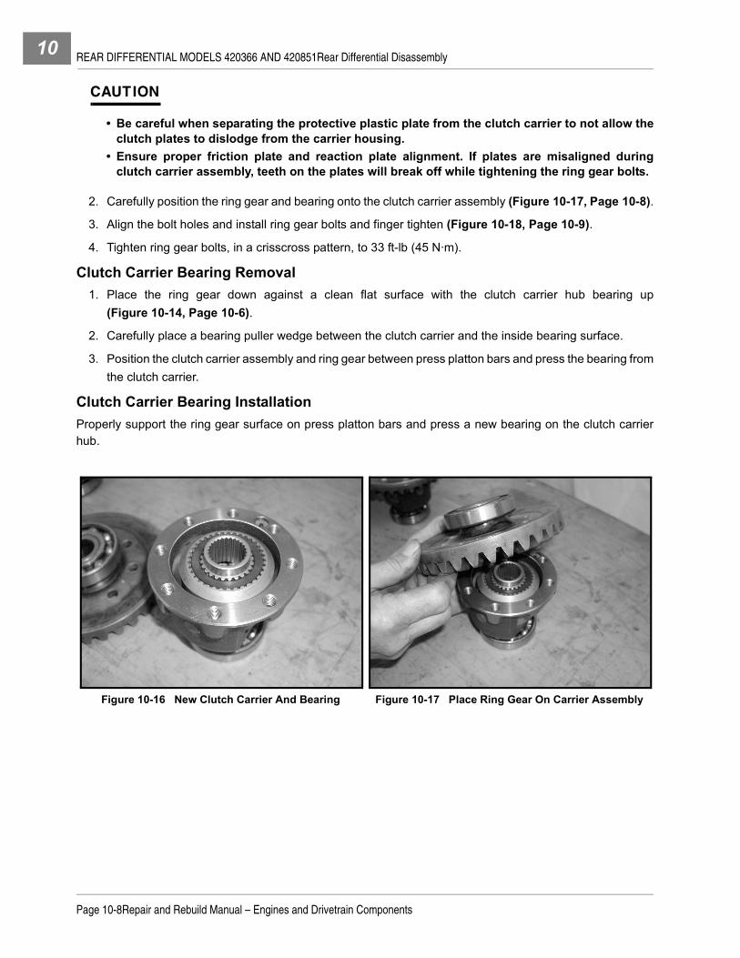
REAR DIFFERENTIAL MODELS 420366 AND 420851Rear Differential Disassembly10
CAUTION
• Be careful when separating the protective plastic plate from the clutch carrier to not allow theclutch plates to dislodge from the carrier housing.
• Ensure proper friction plate and reaction plate alignment. If plates are misaligned duringclutch carrier assembly, teeth on the plates will break off while tightening the ring gear bolts.
2. Carefully position the ring gear and bearing onto the clutch carrier assembly (Figure 10-17, Page 10-8).
3. Align the bolt holes and install ring gear bolts and finger tighten (Figure 10-18, Page 10-9).
4. Tighten ring gear bolts, in a crisscross pattern, to 33 ft-lb (45 N·m).
Clutch Carrier Bearing Removal1. Place the ring gear down against a clean flat surface with the clutch carrier hub bearing up
(Figure 10-14, Page 10-6).
2. Carefully place a bearing puller wedge between the clutch carrier and the inside bearing surface.
3. Position the clutch carrier assembly and ring gear between press platton bars and press the bearing fromthe clutch carrier.
Clutch Carrier Bearing InstallationProperly support the ring gear surface on press platton bars and press a new bearing on the clutch carrierhub.
Figure 10-16 New Clutch Carrier And Bearing Figure 10-17 Place Ring Gear On Carrier Assembly
Page 10-8Repair and Rebuild Manual – Engines and Drivetrain Components

REAR DIFFERENTIAL MODELS 420366 AND 420851Rear Differential Disassembly 10
RING GEAR INSTALLATION1. Position the differential housing so that the fill plug is to the back and left (Figure 10-19, Page 10-9).2. Position the ring gear, bearings and clutch carrier assembly into the differential housing with the ring gear
to the right, or driver side of the housing cavity (Figure 10-21, Page 10-9).3. Seat the ring gear bearing into the driver side housing groove and the clutch carrier bearing into the pas-
senger side housing groove.
4. Install two new oil seals (14), one on each side of the ring gear and carrier assembly, and seat them inhousing (Figure 10-4, Page 10-3). Also see Figure 10-21, Page 10-9.
PINION GEAR INSTALLATION1. Position the pinion gear assembly into the differential housing, meshing the pinion gear with the ring gear
(Figure 10-22, Page 10-10).
Figure 10-18 Install Ring Gear Bolts Figure 10-19 Position Differential Housing
Figure 10-20 Place Ring Gear In Differential Housing Figure 10-21 Driver Side Ring Gear Seal
Repair and Rebuild Manual – Engines and Drivetrain ComponentsPage 10-9

REAR DIFFERENTIAL MODELS 420366 AND 420851Rear Differential Disassembly10
2. Seat bearings and align large thin pinion bearing washer in housing groove (Figure 10-23, Page 10-10).
REAR DIFFERENTIAL ASSEMBLY1. Provide a continuous 1/8 inch (3 mm) wide bead of ThreeBond® 1215 gasket compound to the bolt
flange on the bottom half of the differential housing (Figure 10-25, Page 10-11). See following NOTE.
NOTE: Make sure that the bolt flanges on both halves of the differential housing are clean of old gasketmaterial and dirt and are dry before applying gasket compound.
2. Place the top half of the differential housing on the bottom half, making sure that the three oil seals andbearings align in their respective grooves.
3. Install a new oil seal on the splined end of the pinion shaft and seat in housing (Figure 10-24,Page 10-11).
4. Install the four hex flanged-head bolts in the larger ring gear cavity first, and finger tighten (Figure 10-26,Page 10-11).
5. Install the four hex flanged-head bolts in the pinion cavity last, and finger tighten.
6. Tighten the ring gear cavity bolts first, using a criss cross pattern, with bolt number nine last, to 25 ft-lb(34 N·m) (Figure 10-27, Page 10-11).
7. Tighten the pinion gear cavity bolts last, using a criss cross pattern to 25 ft-lb (34 N·m).
8. Clean and install the drain plug and washer before filling the rear differential with new lubricant. Tightenthe drain plug to 8 ft-lb (10.8 N·m)
9. Add 20 oz. (600mL) Mobile 424, Exxon Hydraul 560, or Esso Hydraul 56 lubricant. Use a funnel whenfilling the differential through the lubricant level indicator hole (1).
Figure 10-22 Place Pinion Gear In Housing Figure 10-23 Align Pinion Bearing Washer In Groove
Page 10-10Repair and Rebuild Manual – Engines and Drivetrain Components

REAR DIFFERENTIAL MODELS 420366 AND 420851Axle Shafts and Differential Installation 10
10. Apply Loctite 567 to the threads of the level indicator plug, and tighten to 21 ft-lb (28 N·m).
AXLE SHAFTS AND DIFFERENTIAL INSTALLATION
See Rear Differential and Axles in the appropriate maintenance and service manual.
Figure 10-24 Pinion Shaft Oil Seal Figure 10-25 Apply ThreeBond 1215 Compound
Figure 10-26 Install Housing Bolts Figure 10-27 Bolt Tightening Sequence
158
4
26 7 3
9
Repair and Rebuild Manual – Engines and Drivetrain ComponentsPage 10-11

REAR DIFFERENTIAL MODELS 420366 AND 420851Axle Shafts and Differential Installation10
Page 10-12Repair and Rebuild Manual – Engines and Drivetrain Components

11
SECTION 11 – TRANSAXLE MODEL UV30Cý DANGER
• See General Warning on page 1-1.
ý WARNING
• See General Warning on page 1-1.
GENERAL INFORMATION
The UV30C model transaxle is designed for both forward and reverse power with splined input and outputshafts (Figure 11-1, Page 11-1 and Figure 11-2, Page 11-1). 4x4 models have an added PTO unit mountedon the passenger-side to drive the front differential.
RATIOSFinal Drive Ratio: Forward - 18.186:1; Reverse - 34.371:1PTO Ratio (4x4 version only): Forward - 3.529:1; Reverse - 6.669:1Approved Lubricant: SAE 10W-30 API Service Class SF, SG, SH, SJ or higher.
TOOLS REQUIRED FOR THIS SECTION
Figure 11-1 Transaxle with Optional PTO – Rear Figure 11-2 Transaxle with Optional PTO – Front
Hydraulic press Large flat blade screwdriver or pry bar 11 mm combination wrenchExternal snap ring pliers Ratchet wrench 13 mm combination wrenchGear puller Torque wrench 15 mm combination wrenchBearing puller wedge attachment 13 mm socket 21 mm combination wrenchPlastic or rubber mallet 15 mm socket SealantBall peen hammer 21 mm socket Thread-locking compoundPunch 10 mm combination wrench Dial gauge
Repair and Rebuild Manual – Engines and Drivetrain ComponentsPage 11-1

TRANSAXLE MODEL UV30CGeneral Information11
EXPLODED VIEWS
Figure 11-3 Exploded View – Differential, Input Shaft and Ouput Shafts
24
23
25
332627
29
28
22
20
19
30
15
11
13
9
108
32
16
31
14
16
12
57
65
3
4
12
2110
8
139
17
18
38
3736
35
34
1514
21
Page 11-2Repair and Rebuild Manual – Engines and Drivetrain Components

TRANSAXLE MODEL UV30CGeneral Information 11
ITEM DESCRIPTION ITEM DESCRIPTION
1 Thrust Washer 20 Dip Stick
2 Idler Gear 21 O-Ring
3 Differential Pin 22 Case Bolt
4 Spring Pin 23 Input Shaft Bearing
5 Thrust Washer 24 Input Shaft
6 Diff. Side Gear – thin 25 Gear
7 Diff. Side Gear – thick, with teeth 26 Washer
8 Oil Seal 27 Snap Ring
9 Circlip 28 Input Shaft Bearing
10 Output Shaft 29 Seal Sleeve
11 Output Shaft Flange (driver-side) 30 Oil Seal
12 Output Shaft Flange (passenger-side) 31 Level Check Plug
13 Flange Bolt 32 O-Ring
14 Gasket 33 Bearing
15 Output Shaft Bearing 34 Ring Gear Bolt
16 Dowel Pin 35 Differential Carrier
17 Drain Plug 36 Differential Lock Slider
18 Drain Plug Seal 37 Ring Gear
19 Dowel Pin 38 Bearing
Repair and Rebuild Manual – Engines and Drivetrain ComponentsPage 11-3

TRANSAXLE MODEL UV30CGeneral Information11
Figure 11-4 Exploded View – Idler, Reduction and Diff. Lock Shafts
46
47
48
49
70
50
51
45
4443
4241
4039
52
73
53
71
72
74
64
63
6261
6059
5857
56
55 54
66
67
6568
69
4x4
4x2
79
77
80
75
8182
83
84
76
78
Page 11-4Repair and Rebuild Manual – Engines and Drivetrain Components

TRANSAXLE MODEL UV30CGeneral Information 11
ITEM DESCRIPTION ITEM DESCRIPTION
39 Spring Pin 62 Snap Ring
40 Idle Reverse Shaft 63 Splined Collar
41 Washer 64 Forward Gear
42 Needle Bearing 65 Needle Bearings
43 Gear 66 Washer
44 Needle Bearing 67 Reduction Shaft (4x4 version)
45 Washer 68 Reduction Shaft (4x2 version)
46 Neutral Switch 69 Reduction Shaft Bearing
47 O-Ring 70 Shift Arm
48 Keeper Plate Bolt 71 Fork Shaft
49 Keeper Plate 72 Shift Fork
50 Collar 73 Springs and Steel Ball
51 O-Rings 74 Collar
52 Reduction Shaft Bearing 75 Diff. Lock Lever
53 Washer 76 Spring Pin
54 Snap Ring 77 O-Ring
55 Collar 78 Pins
56 Washer 79 Differential Lock Shaft
57 Needle Bearing 80 Washer
58 Reverse Gear 81 Shift Fork
59 Needle Bearing 82 Spring
60 Washer 83 Washer
61 Shifter Slider 84 Snap Ring
Repair and Rebuild Manual – Engines and Drivetrain ComponentsPage 11-5

TRANSAXLE MODEL UV30CGeneral Information11
Figure 11-5 Exploded View – PTO Unit
8687
88
97
119118
8590
91 9293
109110
111
108
95
89
94
96
99
100
102
101103
98
107
105104
106
112
114
115
4x2
4x4
117
116
113
Page 11-6Repair and Rebuild Manual – Engines and Drivetrain Components

TRANSAXLE MODEL UV30CGeneral Information 11
ITEM DESCRIPTION ITEM DESCRIPTION
85 Cap Bolt 103 Housing Bolt – Long
86 PTO Shaft Cap 104 Small Plug
87 O-Ring 105 Large Plug
88 Shift Shaft 106 Housing Bolt – Short
89 Shift Block 107 PTO Housing
90 Oil Seal 108 Dowel Pin
91 PTO Shaft Bearing 109 Shim(s)
92 Shift Slider 110 Bearing
93 Circlip 111 26 Tooth Gear
94 Outer PTO Shaft 112 20 Tooth Gear
95 Spring 113 Bearing
96 Steel Balls 114 Gasket
97 Inner PTO Shaft 115 Mounting Plate Bolt
98 Bearing 116 PTO Mounting Plate
99 Keeper Plate Bolt 117 Gasket
100 Keeper Plate 118 PTO Delete Plate
101 Collar 119 Delete Plate Bolt
102 O-Ring
Repair and Rebuild Manual – Engines and Drivetrain ComponentsPage 11-7

TRANSAXLE MODEL UV30CTransaxle Removal11
TRANSAXLE REMOVAL
See the Transaxle Removal section in the appropriate maintenance and service manual.
TRANSAXLE DISASSEMBLY
See General Warning on page 1-1.1. Clean the unit before disassembling. See following CAUTION.
CAUTION
• To prevent damage to seals, do not use thinner or chemical fluid to clean unit.
2. Remove drain plug and drain oil (Figure 11-6, Page 11-8). See following NOTE.
NOTE: Dispose of used oil according to the environmental laws and regulations for your area.
OUTPUT SHAFTS3. Remove eight bolts securing each output shaft flange. Remove driver-side and passenger-side output
shafts and flanges from transaxle (Figure 11-7, Page 11-8).
Figure 11-6 Drain Plug Figure 11-7 Remove Output Shaft Flange Bolts and Flanges
Page 11-8Repair and Rebuild Manual – Engines and Drivetrain Components

TRANSAXLE MODEL UV30CTransaxle Disassembly 11
FRONT DRIVE (PTO) UNIT4. Remove bolt and shift shaft keeper plate (Figure 11-8, Page 11-9).5. Remove eight bolts, securing front drive housing to transaxle, and remove front drive unit (Figure 11-9,
Page 11-9).
6. Remove four bolts and PTO shaft cap (Figure 11-10, Page 11-9).7. Pull shift shaft up and remove shift block from shift arm (Figure 11-11, Page 11-9).
8. Remove outer PTO shaft (Figure 11-12, Page 11-10).
Figure 11-8 Remove Keeper Plate Figure 11-9 Remove Front Drive Unit
Figure 11-10 Remove PTO Shaft Cap Figure 11-11 Remove Shift Block From Shift Arm
Repair and Rebuild Manual – Engines and Drivetrain ComponentsPage 11-9
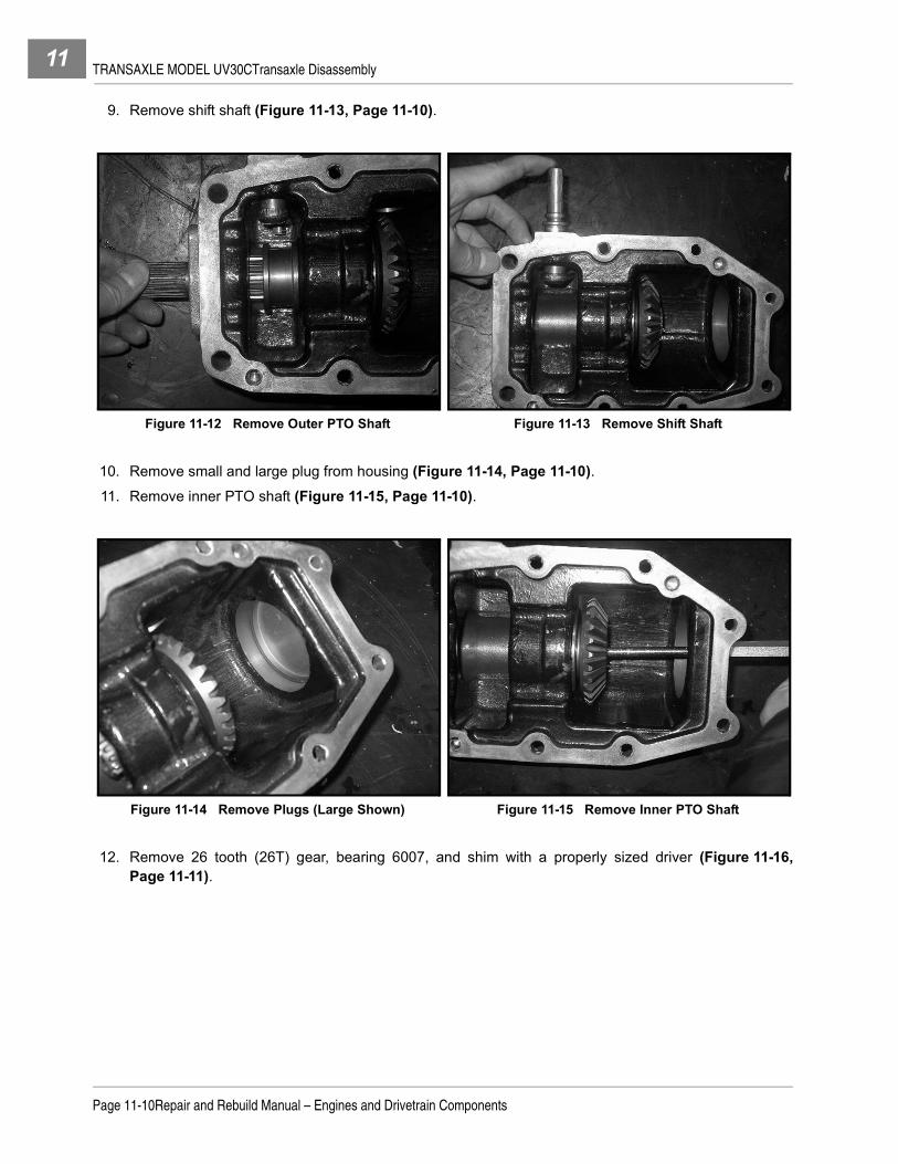
TRANSAXLE MODEL UV30CTransaxle Disassembly11
9. Remove shift shaft (Figure 11-13, Page 11-10).
10. Remove small and large plug from housing (Figure 11-14, Page 11-10).11. Remove inner PTO shaft (Figure 11-15, Page 11-10).
12. Remove 26 tooth (26T) gear, bearing 6007, and shim with a properly sized driver (Figure 11-16,Page 11-11).
Figure 11-12 Remove Outer PTO Shaft Figure 11-13 Remove Shift Shaft
Figure 11-14 Remove Plugs (Large Shown) Figure 11-15 Remove Inner PTO Shaft
Page 11-10Repair and Rebuild Manual – Engines and Drivetrain Components

TRANSAXLE MODEL UV30CTransaxle Disassembly 11
13. Pull bearing 6007 from 26T gear (Figure 11-17, Page 11-11).
14. Press bearing 6205 off inner PTO shaft (Figure 11-18, Page 11-11). See following NOTE.
NOTE: Push against the inner race of bearing.
15. Remove shifter collar from outer PTO shaft (Figure 11-19, Page 11-11). See following NOTE.
NOTE: Steel ball and spring will come out when removing shifter collar.
16. Remove circlip from groove on end of outer PTO shaft.
17. Press bearing 6205 from outer PTO shaft (Figure 11-20, Page 11-12). See following NOTE.
NOTE: Push against the inner race of bearing.
Figure 11-16 Drive 26T Gear and Bearing Assembly From Housing
Figure 11-17 Pull Bearing From 26T Gear
Figure 11-18 Drive Bearing from Inner PTO Shaft Figure 11-19 Remove Shifter Collar From PTO Shaft
Repair and Rebuild Manual – Engines and Drivetrain ComponentsPage 11-11

TRANSAXLE MODEL UV30CTransaxle Disassembly11
18. Remove five bolts, securing front drive mounting plate to transaxle, and remove mounting plate(Figure 11-21, Page 11-12).
19. Pull 20 tooth (20T) gear and bearing 6006 assembly from mounting plate (Figure 11-22, Page 11-12).
Figure 11-20 Drive Bearing Off Outer PTO Shaft Figure 11-21 Remove Mounting Plate From Transaxle
Figure 11-22 Remove Gear and Bearing from Mount-ing Plate
Page 11-12Repair and Rebuild Manual – Engines and Drivetrain Components

TRANSAXLE MODEL UV30CTransaxle Disassembly 11
CASE20. Remove bolt and shifter shaft keeper plate (Figure 11-23, Page 11-13).21. Remove dip stick and neutral switch (Figure 11-24, Page 11-13).
22. Remove sixteen bolts securing case halves together (Figure 11-25, Page 11-13).23. Separate the driver-side casing and remove. See following NOTE.
NOTE: Insert a tool or large screw driver at locations shown (Figure 11-26, Page 11-13 and Figure 11-27,Page 11-14) to force the casing apart. Do not damage the sealing surfaces.
Figure 11-23 Remove Keeper Plate Figure 11-24 Remove Dip Stick and Neutral Switch
Figure 11-25 Remove Casing Bolts Figure 11-26 Pry Casing Halves Apart At This Loca-tion
Repair and Rebuild Manual – Engines and Drivetrain ComponentsPage 11-13

TRANSAXLE MODEL UV30CTransaxle Disassembly11
24. Remove sealant with scraper (Figure 11-28, Page 11-14).25. Remove input shaft from passenger-side casing (Figure 11-29, Page 11-14).26. Remove reverse idle shaft and gear from housing (Figure 11-30, Page 11-14).
27. Remove final gear from case (Figure 11-31, Page 11-15).
Figure 11-27 Carefully Remove Driver–Side Casing Figure 11-28 Scrape Sealant From Mating Surface
Figure 11-29 Remove Input Shaft Figure 11-30 Remove Reverse Idle Shaft
Page 11-14Repair and Rebuild Manual – Engines and Drivetrain Components

TRANSAXLE MODEL UV30CTransaxle Disassembly 11
28. Pull shifter arm up and remove reduction shaft and shift fork at same time (Figure 11-32, Page 11-15).
29. Remove input shaft bearing from case (Figure 11-33, Page 11-15).30. Remove spring pin and slide differential lock lever off shaft (Figure 11-34, Page 11-15).
31. Remove differential lock shaft and fork from case (Figure 11-35, Page 11-16).
Figure 11-31 Remove Final Gear Figure 11-32 Lift Shifter Arm Clear of Shift Fork and Remove Reduction Shaft and Shift Fork
Figure 11-33 Remove Input Shaft Bearing Figure 11-34 Remove Pin and Differential Lock Lever
Repair and Rebuild Manual – Engines and Drivetrain ComponentsPage 11-15

TRANSAXLE MODEL UV30CTransaxle Disassembly11
32. Remove shifter shaft and arm from case (Figure 11-36, Page 11-16).
33. If required, remove air vent from case (Figure 11-37, Page 11-16). See following NOTE.
NOTE: Do not remove air vent if it is not necessary to replace.
CASE INSPECTION1. Inspect case for cracks and worn bearing cavities.
2. If any bearing seat has become worn or damaged, both halves will have to be replaced.
Figure 11-35 Remove Differential Lock Shaft and Fork Figure 11-36 Remove Shifter Shaft And Arm
Figure 11-37 Remove Air Breather Figure 11-38 Input Shaft
Page 11-16Repair and Rebuild Manual – Engines and Drivetrain Components

TRANSAXLE MODEL UV30CTransaxle Disassembly 11
INPUT SHAFT
3. Pull bearing from end of shaft (Figure 11-39, Page 11-17).
4. Pull other bearing and SI sleeve, at same time, from other end of shaft (Figure 11-40, Page 11-17).
5. Remove snap ring and slide washer and gear off (Figure 11-41, Page 11-17).
Figure 11-39 Remove Bearing From End of Shaft Figure 11-40 Remove Bearing and Sleeve Together
Figure 11-41 Remove Snap Ring Figure 11-42 Input Shaft Components
Repair and Rebuild Manual – Engines and Drivetrain ComponentsPage 11-17

TRANSAXLE MODEL UV30CTransaxle Disassembly11
IDLE SHAFT6. Remove washers, needle bearings and idle gear from idle shaft (Figure 11-43, Page 11-18).7. Drive out spring pin from idle shaft (Figure 11-44, Page 11-18)
DIFFERENTIAL
8. Remove fourteen bolts securing ring gear to differential and remove ring gear (Figure 11-46,Page 11-19).
Figure 11-43 Remove Washers, Needle Bearings and Idle Gear
Figure 11-44 Drive Pin from Idle Shaft
Figure 11-45 Differential
Page 11-18Repair and Rebuild Manual – Engines and Drivetrain Components

TRANSAXLE MODEL UV30CTransaxle Disassembly 11
9. Pull bearing from differential (Figure 11-47, Page 11-19).
10. Remove differential lock slider (Figure 11-48, Page 11-19).11. Drive out spring pin to release pinion shaft (Figure 11-49, Page 11-19).
12. Drive pinion shaft from differential (Figure 11-50, Page 11-20).
Figure 11-46 Remove Ring Gear Bolts Figure 11-47 Pull Bearing from End with Slider
Figure 11-48 Remove Differential Lock Slider Figure 11-49 Remove Pin Securing Pinion Shaft
Repair and Rebuild Manual – Engines and Drivetrain ComponentsPage 11-19

TRANSAXLE MODEL UV30CTransaxle Disassembly11
13. Note gear orientation and remove two idler gears and thrust washers first. Then remove two differentialside gears and thrust washers (Figure 11-51, Page 11-20).
14. Remove bearing (Figure 11-52, Page 11-20).
Figure 11-50 Remove Pinion Shaft Figure 11-51 Remove Gears
Figure 11-52 Pull Bearing from Ring Gear End
Page 11-20Repair and Rebuild Manual – Engines and Drivetrain Components

TRANSAXLE MODEL UV30CTransaxle Disassembly 11
REDUCTION SHAFT
15. Remove bearing, and washer behind it, from splined end of shaft (Figure 11-54, Page 11-21 andFigure 11-55, Page 11-21).
16. Remove snap ring, collar and washer (Figure 11-56, Page 11-22).
Figure 11-53 Reduction Shaft Assembly
Figure 11-54 Remove Bearing Figure 11-55 Remove Washer
Repair and Rebuild Manual – Engines and Drivetrain ComponentsPage 11-21

TRANSAXLE MODEL UV30CTransaxle Disassembly11
17. Remove reverse gear, two needle bearings and washer (Figure 11-57, Page 11-22).
18. Remove snap ring, splined collar and shifter slider (Figure 11-58, Page 11-22).19. Remove forward gear, two needle bearings and washer (Figure 11-59, Page 11-22).
Figure 11-56 Remove Snap Ring, Collar and Washer Figure 11-57 Reverse Gear
Figure 11-58 Remove Snap Ring, Collar and Shifter Slider
Figure 11-59 Forward Gear
Page 11-22Repair and Rebuild Manual – Engines and Drivetrain Components

TRANSAXLE MODEL UV30CTransaxle Disassembly 11
20. Remove bearing from end of reduction shaft (Figure 11-60, Page 11-23).
SHIFT FORK
21. Remove collar from fork shaft (Figure 11-62, Page 11-23).
22. Remove shift fork (Figure 11-63, Page 11-23). See following NOTE.
NOTE: Steel ball and spring will come out during shift fork removal.
Figure 11-60 Remove Bearing Figure 11-61 Reduction Shaft Components
Figure 11-62 Remove Collar from Shaft Figure 11-63 Remove Shift Fork (Steel Ball and Spring Inside)
Repair and Rebuild Manual – Engines and Drivetrain ComponentsPage 11-23

TRANSAXLE MODEL UV30CTransaxle Disassembly11
DIFFERENTIAL LOCK SHAFT23. Remove snap ring and slide washer, spring and shift fork from shaft (Figure 11-64, Page 11-24).24. Drive out two spring pins and remove o-ring (Figure 11-65, Page 11-24).
Figure 11-64 Remove Snap Ring, Washer, Spring and Fork
Figure 11-65 Spring Pins and O-ring
Page 11-24Repair and Rebuild Manual – Engines and Drivetrain Components

TRANSAXLE MODEL UV30CTransaxle Assembly 11
TRANSAXLE ASSEMBLY
See General Warning on page 1-1.
GENERAL INFORMATION
CAUTION
• Make sure that the inside of both halves of the transaxle case are clean and free of old oil, dirt,old gasket material and debris.
• Be careful to not damage or dislodge the oil seals when inserting shafts through them.
NOTE: Apply grease to o-rings and oil seal lips.
Orient snap rings as instructed.
Tighten bolts to specified torque.
Pay attention to prevent contamination during assembling.
INPUT SHAFT
1. Slide gear and washer onto shaft and secure with snap ring (Figure 11-67, Page 11-25). See followingNOTE.
NOTE: Orient snap ring with the sharp corner edge away from the washer.
2. Press bearing onto shaft (Figure 11-68, Page 11-26). See following NOTE.
NOTE: Push against inner race of bearing.
3. Press seal sleeve onto shaft (Figure 11-69, Page 11-26).
Figure 11-66 Input Shaft Components Figure 11-67 Secure Gear and Washer with Snap Ring
Repair and Rebuild Manual – Engines and Drivetrain ComponentsPage 11-25

TRANSAXLE MODEL UV30CTransaxle Assembly11
NOTE: Do not install the other bearing onto the shaft (Figure 11-70, Page 11-26). It will be installed intocase in a later step.
Figure 11-68 Press Bearing Onto Shaft Figure 11-69 Press Seal Sleeve Onto Shaft
Figure 11-70 Do Not Install Second Bearing On Shaft
Page 11-26Repair and Rebuild Manual – Engines and Drivetrain Components

TRANSAXLE MODEL UV30CTransaxle Assembly 11
IDLE SHAFT4. Assemble in order, washer, needle bearing, idle gear, needle bearing, washer (Figure 11-71,
Page 11-27).5. Drive spring pin into shaft (Figure 11-72, Page 11-27).
NOTE: Install spring pin oriented as shown (Figure 11-73, Page 11-27).
Figure 11-71 Assemble Idle Shaft Components Figure 11-72 Drive Spring Pin Into Shaft
Figure 11-73 Orient Spring Pin Seam As Shown
Repair and Rebuild Manual – Engines and Drivetrain ComponentsPage 11-27

TRANSAXLE MODEL UV30CTransaxle Assembly11
REDUCTION SHAFT
6. Press bearing onto shaft (Figure 11-75, Page 11-28). See following NOTE.
NOTE: Push against inner race of bearing.
7. Assemble in order, washer, two needle bearings and forward gear (Figure 11-76, Page 11-28).
8. Assemble in order, splined collar and shifter slider (Figure 11-77, Page 11-29). See following NOTE.
NOTE: Orient splined collar as shown (Figure 11-78, Page 11-29) with small bore facing forward gear.
9. Assemble in order, snap ring and washer (Figure 11-79, Page 11-29). See following NOTE.
Figure 11-74 Reduction Shaft Components
Figure 11-75 Press Bearing onto Shaft Figure 11-76 Install Forward Gear Components
Page 11-28Repair and Rebuild Manual – Engines and Drivetrain Components

TRANSAXLE MODEL UV30CTransaxle Assembly 11
NOTE: Orient snap ring with the sharp corner edge toward the washer.
10. Assemble in order, two needle bearings and reverse gear (Figure 11-80, Page 11-29).
11. Assemble in order, washer, collar, snap ring and washer (Figure 11-81, Page 11-30). See followingNOTE.
NOTE: Orient snap ring with the sharp corner edge toward the washer.
12. Press bearing onto shaft (Figure 11-82, Page 11-30). See following NOTE.
Figure 11-77 Install Splined Collar and Shifter Slider Figure 11-78 Splined Collar Cross-section1. Smaller Bore 2. Larger Bore
Figure 11-79 Splined Collar Snap Ring and Washer Figure 11-80 Add Bearings and Reverse Gear
1
2
Repair and Rebuild Manual – Engines and Drivetrain ComponentsPage 11-29

TRANSAXLE MODEL UV30CTransaxle Assembly11
NOTE: Push against inner race of bearing.
Figure 11-81 Secure Reverse Gear with Washers,Collar and Snap Ring
Figure 11-82 Press Bearing onto Reduction Shaft
Figure 11-83 Assembled Reduction Shaft
Page 11-30Repair and Rebuild Manual – Engines and Drivetrain Components

TRANSAXLE MODEL UV30CTransaxle Assembly 11
FORK SHAFT
13. Install double spring into the detent hole of shift fork and put steel ball on the larger spring (Figure 11-84,Page 11-31).
14. Insert fork shaft into shift fork (Figure 11-85, Page 11-31). See following NOTE.
NOTE: Push steel ball down with a small tool while installing fork shaft (Figure 11-86, Page 11-31).
15. Place collar onto fork shaft (Figure 11-87, Page 11-31).
Figure 11-84 Insert Springs and Ball Into Fork Figure 11-85 Insert Fork Shaft Into Fork
Figure 11-86 Push Ball Down To Install Fork Shaft Figure 11-87 Collar On Fork Shaft
Repair and Rebuild Manual – Engines and Drivetrain ComponentsPage 11-31

TRANSAXLE MODEL UV30CTransaxle Assembly11
DIFFERENTIAL LOCK SHAFT
16. Lubricate o-ring with grease and place into groove of shaft (Figure 11-88, Page 11-32).
17. Drive two spring pins into differential lock shaft at locations shown (Figure 11-88, Page 11-32). See fol-lowing NOTE.
NOTE: Orient seam of spring pins as shown (Figure 11-89, Page 11-32).
18. Insert shaft through differential lock fork. See following NOTE.
NOTE: Orient differential lock fork as shown (Figure 11-90, Page 11-32).
19. Place spring and washer onto shaft (Figure 11-91, Page 11-32).
20. Push against washer and compress spring enough to secure with snap ring (Figure 11-92, Page 11-33).See following NOTE.
Figure 11-88 O-Ring and Spring Pin Installation Figure 11-89 Spring Pin Seam Orientation
Figure 11-90 Install Fork Shaft Through Fork Figure 11-91 Add Spring and Washer to Fork Shaft
Page 11-32Repair and Rebuild Manual – Engines and Drivetrain Components

TRANSAXLE MODEL UV30CTransaxle Assembly 11
NOTE: Orient snap ring with the sharp corner edge away from the washer.
DIFFERENTIAL
21. Press bearing 6009 onto ring gear end of carrier (Figure 11-93, Page 11-33). See following NOTE.
NOTE: Push against the inner race of bearing.
22. Install differential side gears and thrust plates (one per gear) in carrier as shown (Figure 11-94,Page 11-33). See following NOTE.
NOTE: Install the thin differential side gear on the ring gear side of carrier.
Figure 11-92 Compress Spring and Secure with Snap Ring
Figure 11-93 Press Bearing Onto Carrier Figure 11-94 Install Differential Side Gears andThrust Plates As Shown
Repair and Rebuild Manual – Engines and Drivetrain ComponentsPage 11-33

TRANSAXLE MODEL UV30CTransaxle Assembly11
23. Install differential idler gears and thrust plates (one per gear) in carrier (Figure 11-95, Page 11-34).Rotate idler gears and thrust plates to align with hole in carrier for differential pin.
24. Insert differential pin through carrier, thrust plates and idler gears (Figure 11-96, Page 11-34). Align holein pin with hole in carrier for spring pin installation.
25. Orient seam of spring pin as shown (Figure 11-97, Page 11-34) and drive pin into carrier (Figure 11-98,Page 11-34). See following NOTE.
NOTE: Orient seam of spring pin as shown.
26. With small end of carrier facing up, place ring gear onto carrier with its machined surface against carrierflange (Figure 11-99, Page 11-35). Apply thread-locking compound to ring gear bolts (Figure 11-100,Page 11-35). Insert bolts through carrier flange and thread into ring gear (Figure 11-101, Page 11-35).Tighten bolts to 55 ft-lb (75 N·m).
Figure 11-95 Install Idler Gears and Thrust Plates Figure 11-96 Insert Pin Through Idler Gears
Figure 11-97 Spring Pin Orientation Figure 11-98 Install Spring Pin To Lock Differential PIn
Page 11-34Repair and Rebuild Manual – Engines and Drivetrain Components

TRANSAXLE MODEL UV30CTransaxle Assembly 11
27. Align differential lock slider pins with holes in carrier and set slider into place (Figure 11-102,Page 11-35).
28. Press bearing 6008 onto small end of carrier (Figure 11-103, Page 11-36). See following NOTE.
Figure 11-99 Place Ring Gear Onto Carrier Figure 11-100 Apply Thread-Locking Compound
Figure 11-101 Tighten Bolts To Proper Torque Figure 11-102 Install Diff Lock Slider
Repair and Rebuild Manual – Engines and Drivetrain ComponentsPage 11-35

TRANSAXLE MODEL UV30CTransaxle Assembly11
NOTE: Push against the inner race of bearing.
CASE29. If air vent needs to be installed, apply thread-locking compound and install (Figure 11-105, Page 11-36).
Tighten vent to 72 in-lb (8 N·m).
30. Insert shift arm into case (Figure 11-106, Page 11-36).
31. Place washer onto differential lock shaft and insert shaft into case (Figure 11-107, Page 11-37).32. Install differential lock lever onto differential lock shaft and secure with spring pin (Figure 11-108,
Page 11-37). See following NOTE.
Figure 11-103 Press Bearing Onto Carrier Figure 11-104 Assembled Differential
Figure 11-105 Air Vent Installed Figure 11-106 Insert Shift Arm
Page 11-36Repair and Rebuild Manual – Engines and Drivetrain Components

TRANSAXLE MODEL UV30CTransaxle Assembly 11
NOTE: Direction of split of spring pin (Figure 11-109, Page 11-37).
33. Place bearing 6204 into case (Figure 11-110, Page 11-38).34. Install reduction shaft assembly into case (Figure 11-111, Page 11-38). See following NOTE.
Figure 11-107 Insert Differential Lock Shaft Through Washer and Into Case
Figure 11-108 Attach Differential Lock Lever and Secure with Pin
Figure 11-109 Orientation of Spring Pin
Repair and Rebuild Manual – Engines and Drivetrain ComponentsPage 11-37

TRANSAXLE MODEL UV30CTransaxle Assembly11
NOTE: Fork should be in groove of shifter slider (Figure 11-113, Page 11-38). Shift arm should engage flatsurface of fork (Figure 11-114, Page 11-39).
Figure 11-110 Install Bearing 6204 Figure 11-111 Install Reduction Shaft Assembly
Figure 11-112 Shift Fork Engaging Shifter Slide Figure 11-113 Fork and Slider Properly Engaged
Page 11-38Repair and Rebuild Manual – Engines and Drivetrain Components

TRANSAXLE MODEL UV30CTransaxle Assembly 11
35. Install differential in case (Figure 11-115, Page 11-39). See following NOTE.
NOTE: Fork should in groove of differential lock slider.
36. Install idle shaft assembly into case (Figure 11-116, Page 11-39). See following NOTE.
NOTE: Orient spring pin in shaft so it aligns with groove in driver-side case (Figure 11-117, Page 11-40).
Figure 11-114 Properly Engage Fork and Shift Arm
Figure 11-115 Install Differential Figure 11-116 Install Idle Shaft Assembly
Repair and Rebuild Manual – Engines and Drivetrain ComponentsPage 11-39

TRANSAXLE MODEL UV30CTransaxle Assembly11
37. Install input shaft assembly into case (Figure 11-118, Page 11-40).38. Lubricate two o-rings with grease and install into shift arm grooves (Figure 11-119, Page 11-40).
39. Place collar onto shift arm (Figure 11-120, Page 11-41). Set keeper plate in place over collar and securewith bolt. Tighten bolt to 19 ft-lb (26 N·m).
Figure 11-117 Groove For Pin in Idle Shaft
Figure 11-118 Install Input Shaft Assembly Figure 11-119 Install Shift Arm O-Rings
Page 11-40Repair and Rebuild Manual – Engines and Drivetrain Components
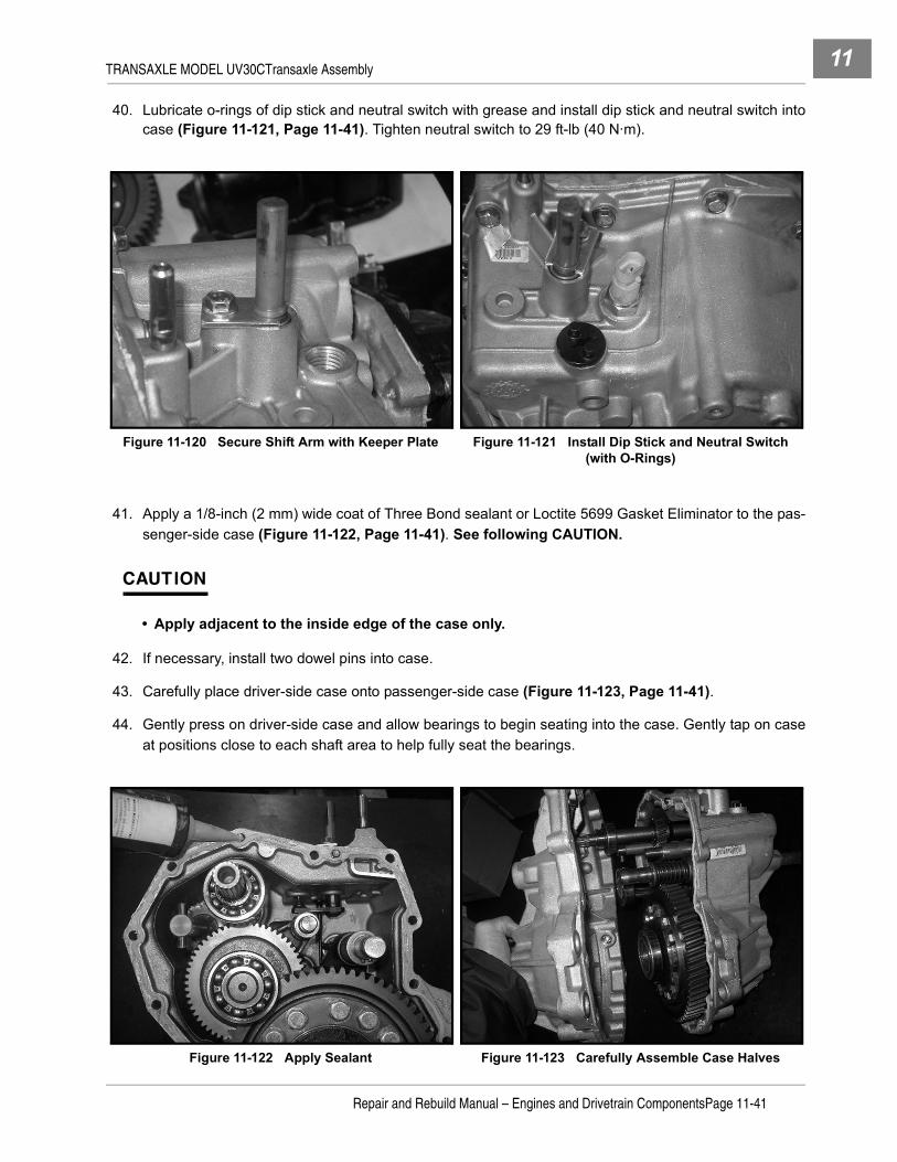
TRANSAXLE MODEL UV30CTransaxle Assembly 11
40. Lubricate o-rings of dip stick and neutral switch with grease and install dip stick and neutral switch intocase (Figure 11-121, Page 11-41). Tighten neutral switch to 29 ft-lb (40 N·m).
41. Apply a 1/8-inch (2 mm) wide coat of Three Bond sealant or Loctite 5699 Gasket Eliminator to the pas-senger-side case (Figure 11-122, Page 11-41). See following CAUTION.
CAUTION
• Apply adjacent to the inside edge of the case only.
42. If necessary, install two dowel pins into case.
43. Carefully place driver-side case onto passenger-side case (Figure 11-123, Page 11-41).
44. Gently press on driver-side case and allow bearings to begin seating into the case. Gently tap on caseat positions close to each shaft area to help fully seat the bearings.
Figure 11-120 Secure Shift Arm with Keeper Plate Figure 11-121 Install Dip Stick and Neutral Switch (with O-Rings)
Figure 11-122 Apply Sealant Figure 11-123 Carefully Assemble Case Halves
Repair and Rebuild Manual – Engines and Drivetrain ComponentsPage 11-41

TRANSAXLE MODEL UV30CTransaxle Assembly11
45. Install sixteen case bolts and tighten the middle area of the case in a criss-cross pattern first, then theends of the case also in a criss-cross pattern to 19 ft-lb (26 N·m) (Figure 11-124, Page 11-42).
46. Install level check plug and tighten to 36 ft-lb (49 N·m) (Figure 11-125, Page 11-42).
47. Assemble washer onto drain plug and tighten to 23 ft-lb (32 N·m) (Figure 11-126, Page 11-42).48. Install oil seal onto input shaft (Figure 11-127, Page 11-42). See following NOTE.
NOTE: Apply grease onto oil seal lip hit outside of oil seal with pipe.
Figure 11-124 Tighten Case Bolts to Proper Torque Figure 11-125 Install Level Check Plug
Figure 11-126 Install Drain Plug Figure 11-127 Install Input Shaft Oil Seal
Page 11-42Repair and Rebuild Manual – Engines and Drivetrain Components

TRANSAXLE MODEL UV30CTransaxle Assembly 11
FRONT DRIVE (PTO) UNIT49. Put spring and steel balls into hole of outer PTO shaft (Figure 11-128, Page 11-43) and assemble shifter
slider (Figure 11-129, Page 11-43). See following NOTE.
NOTE: If replacing shifter slider with new, relocate ball joint stud to toutermost hole on the lever attachedto shift arm.
50. Press bearing 6205 onto outer PTO shaft (Figure 11-130, Page 11-43). See following NOTE.
NOTE: Push against inner race of bearing.
51. Press bearing 6205 onto 26 teeth (26T) gear (Figure 11-131, Page 11-44). See following NOTE.
NOTE: Push against inner race of bearing.
Figure 11-128 Outer PTO Shaft Components Figure 11-129 Capture Spring and Balls withShifter Slider
Figure 11-130 Press Bearing Onto Outer PTO Shaft
Repair and Rebuild Manual – Engines and Drivetrain ComponentsPage 11-43

TRANSAXLE MODEL UV30CTransaxle Assembly11
52. Place shim into bore and install 26T gear (Figure 11-132, Page 11-44).
53. Assemble bearing 6205 onto inner PTO shaft (Figure 11-133, Page 11-44). See following NOTE.
NOTE: Push against inner race of bearing.
54. Install inner PTO shaft assembly into front drive case (Figure 11-134, Page 11-44).
55. Install shift arm (Figure 11-135, Page 11-45).
Figure 11-131 Press Bearing Onto 26T Gear Figure 11-132 Install Shim and 26T Gear
Figure 11-133 Press Bearing Onto Inner PTO Shaft Figure 11-134 Install Inner PTO Shaft Assembly
Page 11-44Repair and Rebuild Manual – Engines and Drivetrain Components

TRANSAXLE MODEL UV30CTransaxle Assembly 11
56. Install outer PTO shaft assembly while placing shift block into shifter slider (Figure 11-136, Page 11-45).
57. Install two o-rings and collar onto shift arm (Figure 11-137, Page 11-45). See following NOTE.
NOTE: Apply grease to the o-ring.
58. Secure shift arm with keeper plate and bolt (Figure 11-138, Page 11-45). Tighten bolt to 19 ft-lb (26N·m).
59. Install o-ring (apply grease) onto front drive cap (Figure 11-139, Page 11-46).60. Press oil seal into front drive cap (Figure 11-139, Page 11-46). See following NOTE.
NOTE: Apply force against the metal outer edge of seal.
Figure 11-135 Install Shift Arm Figure 11-136 Install Outer PTO Shaft Assembly and Engage Shift Arm
Figure 11-137 Install O-Rings and Collar Figure 11-138 Secure Shift Arm with Keeper Plate
Repair and Rebuild Manual – Engines and Drivetrain ComponentsPage 11-45

TRANSAXLE MODEL UV30CTransaxle Assembly11
61. Lubricate oil seal with grease and place cap over outer PTO shaft (Figure 11-140, Page 11-46). Securecap with four bolts. Tighten bolts to 19 ft-lb (26 N·m).
62. Install new circlip into groove on end of outer PTO shaft.
63. If necessary, drive dowel pin into mounting plate.
64. Place small gasket onto mounting plate (Figure 11-141, Page 11-46).
Figure 11-139 Press Oil Seal Into Cap andInstall O-Ring
Figure 11-140 Install Cap
Figure 11-141 Place Small Gasket on Mounting Plate
Page 11-46Repair and Rebuild Manual – Engines and Drivetrain Components

TRANSAXLE MODEL UV30CTransaxle Assembly 11
65. Place mounting plate on case and secure with five bolts (Figure 11-142, Page 11-47). Tighten bolts to19 ft-lb (26 N·m) (Figure 11-143, Page 11-47).
66. Press bearing 6006 onto 20T gear (Figure 11-144, Page 11-47). See following NOTE.
NOTE: Push against inner race of bearing.
67. Insert 20T gear and bearing assembly into mounting plate bore (Figure 11-145, Page 11-47).
68. If necessary, drive two dowel pins into mounting plate.
69. Place gasket onto mounting plate (Figure 11-146, Page 11-48).
Figure 11-142 Place Mounting Plate on Case Figure 11-143 Tighten Mounting Plate Bolts to Proper Torque
Figure 11-144 Press Bearing onto 20T Gear Figure 11-145 Place 20T Gear into Mounting Plate
Repair and Rebuild Manual – Engines and Drivetrain ComponentsPage 11-47

TRANSAXLE MODEL UV30CTransaxle Assembly11
70. Install front drive unit on mounting plate and secure with eight bolts (Figure 11-147, Page 11-48).Tighten the six M8 size bolts to 19 ft-lb (26 N·m). Tighten the two M10 size bolts to 38 ft-lb (52 N·m).
71. Check backlash for proper specification of 0.08 - 0.18 mm. Through small opening, set dial indicator atoutside diameter tooth edge of 26T gear (Figure 11-148, Page 11-48). Holding 20T gear by finger or toolfrom large opening in housing (Figure 11-149, Page 11-48), rotate PTO shaft clockwise and counter-clockwise and read dial indicator. If backlash is out of specification, add/eliminate shims to adjust.
Figure 11-146 Place Large Gasket on Mounting Plate Figure 11-147 Install Front Drive Unit and Tighten Bolts to Proper Torque
Figure 11-148 Setup Dial Indicator to Check Backlash Figure 11-149 Hold 20 Tooth Gear To Prevent Rotation
Page 11-48Repair and Rebuild Manual – Engines and Drivetrain Components

TRANSAXLE MODEL UV30CTransaxle Assembly 11
72. Install small (Figure 11-150, Page 11-49) and large plugs (Figure 11-151, Page 11-49).
OUTPUT SHAFTS
73. Press bearings onto output shafts (Figure 11-152, Page 11-49). See following NOTE.
NOTE: Push against inner race of bearing.
74. Press oil seals into flanges (Figure 11-153, Page 11-49). See following NOTE.
NOTE: Apply force against the metal outer edge of seal.
75. Apply grease to oil seals and install output shafts through flanges (Figure 11-154, Page 11-50).
76. If necessary, install two dowel pins into each side of case (Figure 11-155, Page 11-50).
Figure 11-150 Install Small Plug Figure 11-151 Install Large Plug
Figure 11-152 Press Bearing Onto Output Shaft Figure 11-153 Press Oil Seals Into Output Shaft Flanges
Repair and Rebuild Manual – Engines and Drivetrain ComponentsPage 11-49

TRANSAXLE MODEL UV30CTransaxle Installation11
77. Place gasket onto case.
78. Install output shaft assemblies into case and secure with bolts (Figure 11-156, Page 11-50). Tightenbolts, in a criss-cross pattern, to 38 ft-lb (52 N·m) (Figure 11-157, Page 11-50).
79. Remove dip stick and fill case with 1 gallon (3.79 L) 10W-30 SF, SG, SH oil. Install dip stick finger-tight.
TRANSAXLE INSTALLATION
See Transaxle Installation section in the appropriate maintenance and service manual.
Figure 11-154 Install Output Shaft Through Flange Figure 11-155 Dowel Pins and Gasket
Figure 11-156 Install Output Shafts Figure 11-157 Tighten Bolts to Proper Torque In a Criss-Cross Pattern
Page 11-50Repair and Rebuild Manual – Engines and Drivetrain Components

INDEX
AACR
inspection ................................................. 3-22, 4-3axle half shaft
installation ........................................................9-18removal ..............................................................9-1
axle shaft ................................................ 5-2, 6-2, 7-2axle shaft and differential
installation ......................................................10-11removal ............................................................10-2
axle tubes ......................................... 5-26, 6-26, 7-29
Bball bearing
inspection ............................................... 2-37, 3-38removal .................................................. 2-37, 3-38
breather valve (reed valve) .......................... 2-8, 3-8inspection ............................................... 2-18, 3-18installation .............................................. 2-19, 3-18removal ...................................................... 2-9, 3-9
Ccamshaft
axial play adjustment .......................................3-43inspection .........................................................2-22installation .............................................. 2-42, 3-42removal ............................................................2-22
camshaft and hydraulic lifterinspection .........................................................3-21installation ........................................................3-23removal ............................................................3-22
caseassembly ........................................................11-36disassembly ...................................................11-13
CAUTIONdefinition of .........................................................1-1
clutch and ring gearassembly ..........................................................9-13disassembly .....................................................9-11
clutch carrierassembly ..........................................................10-7bearing installation ...........................................10-8bearing removal ...............................................10-8installation ........................................................10-7removal ............................................................10-7
coil and output coverassembly ............................................................9-5disassembly .......................................................9-4installation ..........................................................9-6removal ..............................................................9-3
connecting rodinspection ............................................... 2-25, 3-25installation .............................................. 2-39, 3-41removal .................................................. 2-22, 3-23separation .............................................. 2-23, 3-23undersized ............................................. 2-36, 3-37
counterbalance guide shaftinspection ............................................... 2-34, 3-35
counterbalance weightbearing replacement ........................................3-35inspection ............................................... 2-34, 3-35
crankcase coverinstallation .............................................. 2-42, 3-44removal .................................................. 2-20, 3-20
crankshaftaxial play adjustment ............................. 2-40, 3-42inspection ............................................... 2-35, 3-36installation .............................................. 2-38, 3-40
crankshaft and counterbalancedisassembly ........................................... 2-31, 3-32removal .................................................. 2-31, 3-32
cylinder block .......................................................4-4inspection ............................................... 2-25, 3-26resize bore ...................................... 2-26, 3-27, 4-5
cylinder boreresizing specifications ..................... 2-46, 3-48, 4-6
cylinder head ......................................... 2-4, 3-4, 4-2cleaning and inspection ............................. 2-9, 3-9installation .............................................. 2-16, 3-16removal ...................................................... 2-7, 3-7
cylinder shroudremoval ...................................................... 2-4, 3-4
DDANGER
definition of .........................................................1-1differential
assembly ........................................................11-33disassembly ...................................................11-18
differential gear caseassembly ....................................... 5-19, 6-17, 7-20disassembly ........................................ 5-9, 6-8, 7-8
differential gear lock housingassembly ................................................ 6-19, 7-22disassembly ............................................... 6-7, 7-7
differential lock housingassembly ................................................ 6-19, 7-22disassembly ............................................... 6-7, 7-7
differential lock shaftassembly ........................................................11-32disassembly ...................................................11-24
Repair and Rebuild Manual – Engines and Drivetrain ComponentsPage i-1

INDEX
differential, frontsee front differential
differential, rearsee rear differential
Eengine, fe290
adjustments and settings ................................. 2-47assembly .........................................................2-43boring ...............................................................2-46component installation ..................................... 2-19general information ............................................ 2-1installation ........................................................ 2-44mechanical systems .......................................... 2-2replacement parts .............................................. 2-2rotation ............................................................... 2-4service specifications ....................................... 2-45service tools ....................................................... 2-1
engine, fe350adjustments and settings ................................. 3-49assembly .........................................................3-45boring ...............................................................3-48component installation ..................................... 3-18general information ............................................ 3-1installation ........................................................ 3-46mechanical systems .......................................... 3-2replacement parts .............................................. 3-2rotation ............................................................... 3-4service specifications ....................................... 3-47service tools ....................................................... 3-1
engine, fe400see fe350 engine components except for those listed
belowACR valve inspection ........................................ 4-3adjustments and settings ................................... 4-6boring .................................................................4-6crankshaft and counterbalance weight .............. 4-5cylinder block ..................................................... 4-4cylinder head ..................................................... 4-2general information ............................................ 4-1installation .......................................................... 4-6muffler removal and installation ......................... 4-3piston and connecting rod ................................. 4-5replacement parts .............................................. 4-2resize bore ......................................................... 4-5service specifications ......................................... 4-6service tools ....................................................... 4-1
Fflywheel
installation ...............................................2-43, 3-45removal ...................................................2-27, 3-28
fork shaftassembly ....................................................... 11-31
front differentialassembly ......................................................... 9-14backlash adjustment .......................................... 9-7coil and output cover ......................................... 9-3disassembly ....................................................... 9-8general information ............................................ 9-1installation ........................................................ 9-18removal .............................................................. 9-2
front drive unitassembly ....................................................... 11-43disassembly ..................................................... 11-9
Ggovernor gear
assembly .......................................5-21, 6-19, 7-22disassembly .........................................5-6, 6-7, 7-7
Iidle shaft
assembly ....................................................... 11-27disassembly ................................................... 11-18
idler shaftassembly .......................................5-14, 6-14, 7-15disassembly ...................................5-13, 6-12, 7-14
ignition coilinstallation ...............................................2-27, 3-28removal ...................................................2-27, 3-28
input shaftassembly ................................................8-8, 11-25disassembly ............................................8-8, 11-17
input shaft sealinstallation ........................................................ 9-10removal ............................................................ 9-10
inspectionautomatic compression relief valve (ACR) 3-22, 4-3ball bearing .............................................2-37, 3-38breather valve (reed valve) .....................2-18, 3-18camshaft .......................................................... 2-22camshaft and hydraulic lifter ............................ 3-21connecting rod ........................................2-25, 3-25counterbalance guide shaft ....................2-34, 3-35counterbalance weight ............................2-34, 3-35crankshaft ...............................................2-35, 3-36cylinder block ..........................................2-25, 3-26cylinder head ..................................................... 2-9link rod ....................................................2-33, 3-34oil pressure relief valve .................................... 2-30oil pump ..................................................2-29, 3-30piston ......................................................2-23, 3-24
Page i-2Repair and Rebuild Manual – Engines and Drivetrain Components
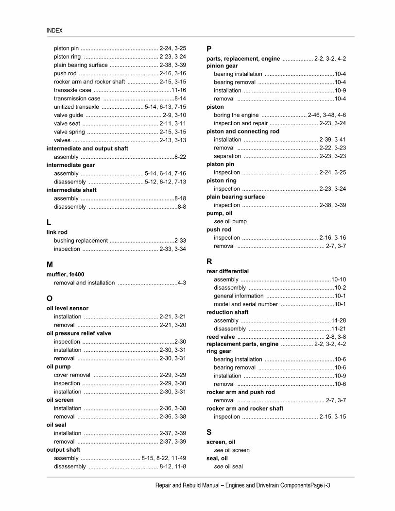
INDEX
piston pin ................................................ 2-24, 3-25piston ring .............................................. 2-23, 3-24plain bearing surface .............................. 2-38, 3-39push rod ................................................. 2-16, 3-16rocker arm and rocker shaft ................... 2-15, 3-15transaxle case ................................................11-16transmission case ............................................8-14unitized transaxle .......................... 5-14, 6-13, 7-15valve guide ............................................... 2-9, 3-10valve seat ............................................... 2-11, 3-11valve spring ............................................ 2-15, 3-15valves ..................................................... 2-13, 3-13
intermediate and output shaftassembly ..........................................................8-22
intermediate gearassembly ....................................... 5-14, 6-14, 7-16disassembly .................................. 5-12, 6-12, 7-13
intermediate shaftassembly ..........................................................8-18disassembly .......................................................8-8
Llink rod
bushing replacement ........................................2-33inspection ............................................... 2-33, 3-34
Mmuffler, fe400
removal and installation .....................................4-3
Ooil level sensor
installation .............................................. 2-21, 3-21removal .................................................. 2-21, 3-20
oil pressure relief valveinspection .........................................................2-30installation .............................................. 2-30, 3-31removal .................................................. 2-30, 3-31
oil pumpcover removal ........................................ 2-29, 3-29inspection ............................................... 2-29, 3-30installation .............................................. 2-30, 3-31
oil screeninstallation .............................................. 2-36, 3-38removal .................................................. 2-36, 3-38
oil sealinstallation .............................................. 2-37, 3-39removal .................................................. 2-37, 3-39
output shaftassembly ..................................... 8-15, 8-22, 11-49disassembly ........................................... 8-12, 11-8
Pparts, replacement, engine ................... 2-2, 3-2, 4-2pinion gear
bearing installation ...........................................10-4bearing removal ...............................................10-4installation ........................................................10-9removal ............................................................10-4
pistonboring the engine ............................ 2-46, 3-48, 4-6inspection and repair .............................. 2-23, 3-24
piston and connecting rodinstallation .............................................. 2-39, 3-41removal .................................................. 2-22, 3-23separation .............................................. 2-23, 3-23
piston pininspection ............................................... 2-24, 3-25
piston ringinspection ............................................... 2-23, 3-24
plain bearing surfaceinspection ............................................... 2-38, 3-39
pump, oilsee oil pump
push rodinspection ............................................... 2-16, 3-16removal ...................................................... 2-7, 3-7
Rrear differential
assembly ........................................................10-10disassembly .....................................................10-2general information ..........................................10-1model and serial number .................................10-1
reduction shaftassembly ........................................................11-28disassembly ...................................................11-21
reed valve ...................................................... 2-8, 3-8replacement parts, engine .................... 2-2, 3-2, 4-2ring gear
bearing installation ...........................................10-6bearing removal ...............................................10-6installation ........................................................10-9removal ............................................................10-6
rocker arm and push rodremoval ...................................................... 2-7, 3-7
rocker arm and rocker shaftinspection ............................................... 2-15, 3-15
Sscreen, oil
see oil screenseal, oil
see oil seal
Repair and Rebuild Manual – Engines and Drivetrain ComponentsPage i-3

INDEX
service toolsengine ..................................................2-1, 3-1, 4-1front differential .................................................. 9-3rear differential ................................................. 10-1transmission .............................................8-2, 11-1unitized transaxle ......... 5-2, 6-2, 7-2, 8-2, 9-3, 11-1
shaft sealinstallation ........................................................ 8-15removal ............................................................ 8-15
shift forkdisassembly ...................................................11-23
shifter forkassembly .......................................5-18, 6-16, 7-19disassembly ...................................5-11, 6-10, 7-12
shifter shaftinstallation ........................................................ 8-14removal ............................................................ 8-13
specificationsengine service .................................2-45, 3-47, 4-6torque ..............................................2-46, 3-48, 4-6
synchronizer gearassembly .......................................5-15, 6-14, 7-16disassembly ...................................5-11, 6-10, 7-12
Ttappets ................................................................ 2-22tools
see service toolstorque specifications .........................2-46, 3-48, 4-6transaxle
assembly .......................................................11-25case inspection ..............................................11-16disassembly ..................................................... 11-8installation ......................................................11-50removal ............................................................ 11-8see unitzed transaxle
transmissionassembly .........................................................8-23case inspection ................................................ 8-14disassembly ....................................................... 8-2general information ...................................8-1, 11-1identification ....................................................... 8-1installation ........................................................ 8-27removal .............................................................. 8-2service fixture .................................................... 8-1service tools ..............................................8-2, 11-1
Uunitized transaxle (MC008C-ES00 and MC008C-FS00)
assembly .........................................................5-21component assembly ....................................... 5-14component disassembly .................................... 5-6
component inspection ...................................... 5-14disassembly ....................................................... 5-2identification ....................................................... 5-1installation ........................................................ 5-26lubrication ........................................................ 5-26removal .............................................................. 5-2
unitized transaxle (MC010C-BS00) ..................... 6-1assembly ......................................................... 6-20component assembly ....................................... 6-14component disassembly .................................... 6-7component inspection ...................................... 6-13disassembly ....................................................... 6-2identification ....................................................... 6-1installation ........................................................ 6-26lubrication ........................................................ 6-26removal .............................................................. 6-2
unitized transaxle (MC012C-AS00 and MC012C-BS00)assembly ......................................................... 7-23component assembly ....................................... 7-15component disassembly .................................... 7-7component inspection ...................................... 7-15disassembly ....................................................... 7-2identification ....................................................... 7-1installation ........................................................ 7-29lubrication ........................................................ 7-29removal .............................................................. 7-2
Vvalve
clearance check and adjustment ............2-18, 3-17inspection of valves ................................2-13, 3-13installation ...............................................2-15, 3-15removal .......................................................2-8, 3-8
valve guideinspection .................................................2-9, 3-10replacement ............................................2-10, 3-10
valve seatinspection ...............................................2-11, 3-11repair ......................................................2-12, 3-12
valve springinspection ...............................................2-15, 3-15
valve, automatic compression relief (ACR)inspection .................................................3-22, 4-3
WWARNING
definition of ........................................................ 1-1
Page i-4Repair and Rebuild Manual – Engines and Drivetrain Components


Club Car, Inc.P.O. Box 204658Augusta, GA 30917-4658USA
Web www.clubcar.comPhone 1.706.863.3000 1.800.ClubCarInt’l +1 706.863.3000Fax 1.706.863.5808