cmd, continuous monitoring data base
TRANSCRIPT

CMD, Continuous Monitoring Data Base A web application that stores the continuous monitoring data of a landfill.
Student: Paola Andrea Vera
Director: Dolors Costal
Master Ingeniería Informática
Facultad ingeniería Informática de Barcelona (FIB)
Universidad Politécnica de Catalunya.

1
Contents 1 Introduction .......................................................................................................................................... 3
1.1 Context .......................................................................................................................................... 3
1.2 Starting Point ................................................................................................................................ 5
1.3 Thesis Goals................................................................................................................................... 6
1.4 Glossary ......................................................................................................................................... 8
1.5 Development Methodology .......................................................................................................... 9
1.6 Document structure .................................................................................................................... 10
2 Requirements Specification ................................................................................................................ 11
2.1 Functional Requirements ............................................................................................................ 11
2.1.1 List of use cases ................................................................................................................... 11
2.1.2 Actors .................................................................................................................................. 14
2.1.3 Use cases specification........................................................................................................ 14
2.2 Data conceptual scheme ............................................................................................................. 70
2.3 Non-functional requirements ..................................................................................................... 72
2.3.1 Look and feel requirements ................................................................................................ 72
2.3.2 Usability and humanity requirements ................................................................................ 72
2.3.3 Performance requirements ................................................................................................. 72
2.3.4 Maintainability and support requirements ......................................................................... 74
2.3.5 Security requirements ......................................................................................................... 74
3 System Architecture ............................................................................................................................ 76
3.1 Description .................................................................................................................................. 76
3.2 Used Technologies ...................................................................................................................... 76
3.3 Use case view .............................................................................................................................. 79
3.4 Package view ............................................................................................................................... 80
3.5 Deployment view ........................................................................................................................ 82
3.6 Analysis and Design ..................................................................................................................... 84
3.6.1 Class diagram ...................................................................................................................... 84
3.6.2 Data base diagram .............................................................................................................. 86
3.6.3 Analysis after reverse engineering ...................................................................................... 87
3.6.4 Proof of concept .................................................................................................................. 90
3.6.5 Evaluation of the proof of concept ..................................................................................... 91

2
3.6.6 Sequence Diagram .............................................................................................................. 91
4 Testing ............................................................................................................................................... 107
5 Project planning and costs ................................................................................................................ 108
5.1 Planning..................................................................................................................................... 108
5.2 Actual planning ......................................................................................................................... 109
5.3 Planning conclusions ................................................................................................................. 109
5.4 Costs .......................................................................................................................................... 110
6 Future Work ...................................................................................................................................... 112
7 Conclusions ....................................................................................................................................... 113
8 References ........................................................................................................................................ 115
9 APPENDIX .......................................................................................................................................... 116

3
1 Introduction
1.1 Context
Americans generate trash at rate of 4.6 pounds (2.1 kilograms) per day per person, which
is 251 million tons (228 million metric tons) per year. Some of this trash gets recycled or
recovered and some is burned, but the majority is buried in landfills.
A landfill is a carefully designed structure built into
or on top of the ground in which trash is isolated
from the surrounding environment. A landfill has a
several environmental impacts; that is why it is
important to monitor air, surface water and
groundwater.
Environmental Information Logistics (EIL) [1] is an environmental consulting,
engineering, and information management firm, located in the United States, which
provides economical solutions to the diverse environmental, engineering, and data
management challenges that their clients confront. Its team includes licensed civil,
geotechnical, geological and environmental engineers, professional project managers,
environmental scientists, biologists, chemists, hydrogeologists and technicians.
EIL helps a number of clients, which are waste disposal companies that own and run
landfills, to manage the special compliance and operations of them. One of those

4
operations consists of data management, ordered by the EPA (US Environmental
Protection Agency), which requires monitoring, recordkeeping and reporting of large
amounts of data, generated by several devices (data loggers) located in the landfills or
sites.
It came about that as a company they wanted to serve their client by providing air pollution
compliance through the design of something very flexible in order to accommodate
changing regulations by the EPA. They decided to meet these requirements by the
creation of a web application for this and other future uses, such as applications that
require manipulation of continuous data.
They choose to organize the data by the creation of the concept of the reportable unit,
which is any physical device for which records are kept, such as gas flares, well
pressures, water levels, etc. They can be elements of a landfill or other industrial process
that have to be measured.
Reportable Units generate data and it is recorded by data loggers in csv (comma separate
values) files, where each column is a type of data (temperature, gas, pressure, flow rates,
etc.) and every row is the value of the data according to a timestamp. Usually data is
recorded every 1 minute to 15 minutes, every day and every year.
Besides storing the data, it is necessary to generate different kinds of reports from it,
because the EPA demands it. The algorithms used to create the reports are largely
based on regulatory requirements, helping clients to maintain regulatory compliance.

5
1.2 Starting Point
A few years ago, EIL had few sites to manage and was receiving its data in files each
month. Using this data they would manually build their reports using excel. However,
sometimes a site’s data was messy: multiple data loggers were used or data were
provided in different formats. One person could spend a lot of time figuring out how
to handle it. On occasions, the client would ask for a calculation of the data for a
particular time frame and the person who had figured it out the first time was out of
the office. Someone else would then go through the data again, or the first person’s
calculations and figure it out. Often the second person would get a different number
than the person doing the original calculations.
Five years ago EIL saw the need to create an informatics system (Web application)
that could manage data from their landfills and generate reports. This project was
called "Continuous Management Data base". It began with few requirements, one
programmer and one project manager. The IT of the company decided to use .net as
the programming language, Sql server 2008 as the data base and IIS as the server
application.
The web application consisted of uploading text files, which contain minute-by-minute
data of the different variables that can be measured at a landfill (for example
temperature) and then populating the database with the aim of generating reports to
analyze these data to be delivered to the sites owners.

6
Over time, the requirements of the EPA were increasing and the type of reports that
customers demanded of EIL and its web application, too. In addition, EIL realized that
the database could be used for purposes different from what it was originally designed,
which why the project requirements were changing and growing.
However, during the implementation of the system, the phases of the software
development were done incorrectly, because of poor documentation of requirements
gathering, analysis, system design and testing. By becoming larger, the application
EIL came to the conclusion that it was necessary to have good documentation of all
phases.
Besides this issue new, interesting and complex requirements appeared. Some sites
store the text files where the data is in ftp servers every day and EIL employees
download the data and then upload them into the web application. It is necessary to
automatize this step and give the data base charge of it, speeding up the downloading
–uploading time and reducing the amount of people doing it.
1.3 Thesis Goals
The thesis is divided into three parts:
1. The first consists in documenting the reverse engineering of requirements,
analysis and design of all use cases of the application.

7
2. During the reverse engineering of system many mistakes were found in the
implementation phase, so it was realized that the application code could be
improved. That is why the second part consists of correcting and improving the
application to make it more flexible and understandable. However, EIL didn’t
approve the improvement of all the reverse engineering use cases, due to costs in
time and money. So, it came to the conclusion to improve the most important and
critical use cases
3. New requirements have emerged, which will make a major change in the
application. The third part consists of implementing those requirements following
all of the software development phases. For implementing these requirements a
proof of concept was built for making decisions about the tools to be used to
implement this part of the application.

8
1.4 Glossary
Client: the owner or the administrator of the site. Every site has an owner and an
administrator. In most of the cases the owner is the same administrator.
Continuous data: is data recorded at a high frequency during a time frame.
Daylight saving time: (DST) or summer time is the practice of advancing clocks during
the summer months that have more daylight so that people get up earlier in the morning
and experience more daylight in the evening.
Data Logger: is a device used to record data of a reportable unit stored electronically in
a file.
Data Format: is a file format or template that describes the structure of a data file.
Document: the pdf documents of the company.
File: file generated by a data logger, contains data of the reportable unit by date.
Ftp download: some of the client’s data, which is recorded by data loggers, and is
located in ftp servers. This data has to be downloaded in order to be manipulated and
reported.
Fuel type: is the type of fuel that the reportable unit burns.
Measurement type: is a physical measurement such as temperatures, gas flow rates,
gas flow volume of the reportable unit.
Measurement Unit: is the unit of a physical measurement value.

9
Reportable Unit: is any physical device for which records are kept, such as gas flares,
well pressures, water levels, etc. These records are recorded by data loggers in files.
Site: a landfill or business location which has reportable units, such a flares or engines
or gas hot water heaters.
User: user of the application, such as an administrator type, a simple user or a client.
Baratroll: trade name of a pressure transducer measuring barometric pressure.
Ruggetroll: trade name of a pressure transducer measuring ground water pressure.
Missing data: data that should exist in a period of time.
Runtime: the time period during which a device is operating.
Unit operating: when a reportable unit works as designed.
Unit not operating: when a reportable unit does not work as designed.
1.5 Development Methodology
The software methodology chosen to build the software is the Unified Software
Development Process [2] or Unified Process (UP). However, it has been adapted to
the requirements of the business, just one programmer and the option to have reverse
engineering.

10
UP is an iterative and incremental development process and the requirements of EIL are
constantly growing and changing. Its phases from requirements to deployment are quite
good for what EIL wants.
For the requirement phase it was decided to work with use cases. For the analysis and
design phases sequence diagrams were chosen, using Enterprise Architect [3] as the
tool. For testing, unit tests were selected using Visual Studio to build them.
1.6 Document structure
This Document will be organized by sections. First, all the requirements specification will
be presented; those acquired by the reverse engineering process and the new ones. Then
the architecture of the system will be described. The analysis and design of the new use
cases and the result of analyzing the reverser engineering process.
On the other hand, a proof of concept was created to choose the technology to be used
to implement the new requirements, in this document a short explanation will be
presented, describing how the decision was taken.
Finally this document will explain the testing of the web application, the project planning
and costs, the future work and the conclusions.

11
2 Requirements Specification
2.1 Functional Requirements
2.1.1 List of use cases
This is the list of all the use cases of the application. Most of them were created
after reverse engineering was applied and others by the new requirements. A note
was added to explain how the use case was obtained and if it had to be corrected
or adapted in order to make the application ready to accept the new requirements.
Category ID Use case Note
Facility Set up UC01 Clients Manage clients Reverse. E
UC02 Add Client Reverse. E
UC03 Modify Client Reverse. E
UC04 Delete Client Reverse. E
UC05 Sites Manage sites Reverse. E
UC06 Add site Reverse. E
UC07 Modify site Reverse. E
UC08 Delete site Reverse. E
UC09 Reportable unit
Manage reportable units Reverse. E
UC10 Add reportable unit Reverse. E
UC11 Modify reportable unit Reverse. E
UC12 Delete reportable unit Reverse. E
UC13 Data logger Manage data loggers Reverse. E
UC14 Add Data logger Reverse. E
UC15 Modify Data Logger Reverse. E
UC16 Delete Data Logger Reverse. E
UC17 Data format Manage data formats Reverse. E
UC18 Add data format Reverse. E
UC19 Modify data format Reverse. E
UC20 Delete data format Reverse. E
UC21 Data format items
Manage data formats items Reverse. E
UC22 Add data format items Reverse. E
UC23 Modify data format items Reverse. E
UC24 Delete data format items Reverse. E
Data Deletion UC25 Data deletion by file Reverse. E
UC26 Data deletion by time frame Reverse. E
UC27 Delete duplicated data Implemented
Reverse. E

12
UC28 Large block data deletion Reverse. E
Data Entry UC29 FTP server configuration
Manage FTP Server configuration
New
UC30 Add a FTP Server configuration
New
UC31 Modify a FTP Server configuration
New
UC32 Delete a FTP Server configuration
New
UC33 Add a folder path to a FTP Server configuration
New
UC34 Edit a folder path to a FTP Server configuration
New
UC35 Delete a folder path to a FTP Server configuration
New
UC36 Scheduling ftp download
Manage FTP download schedule
New
UC37 Add FTP download schedule
New
UC38 Modify FTP download schedule
New
UC39 Delete FTP download schedule
New
UC40 Download FTP files New
UC41 Manual FTP download New
UC42 Upload data from a single file
Reverse. E /Corrected
UC43 Upload file Reverse. E/ Improved-Adapted
UC44 Manual entry List manual entries Reverse. E
UC45 Add manual entry Reverse. E
UC46 Modify manual entry Reverse. E
UC47 Delete manual entry Reverse. E
Reporting UC48 Missing data reports
Missing data reports (Daily, weekly, monthly, yearly)
Reverse. E
UC49 Missing data report Reverse. E
UC50 Flow reports Flow report (Daily, weekly, monthly, yearly)
Reverse. E
UC51 Average max, min flow reports (Daily, weekly, monthly, yearly)
Reverse. E
UC52 Back Weighted Flow Report (Daily, weekly, monthly, yearly)
New

13
UC53 Operating reports
Uptime downtime reports (Daily, weekly, monthly, yearly)
Reverse. E
UC54 Venting report Reverse. E
UC55 Query reports
Data report Reverse. E
UC56 Multiple units data report Reverse. E
UC57 Data chart Reverse. E
UC58 Temperature reports
Temperature reports (monthly)
New
UC59 Average, max, min temperature reports (Daily, weekly, monthly, yearly)
Reverse. E
UC60 Special reports
Time shifted 2 minutes data Reverse. E
UC61 Time shifted 5 minutes data Reverse. E
UC62 Site summary report Reverse. E
User UC63 Log in Reverse. E
UC64 Log Out Reverse. E
Administration UC65 User Manage Users Reverse. E
UC66 Add user Reverse. E
UC67 Modify user Reverse. E
UC68 Delete user Reverse. E
UC69 Manage permissions Reverse. E
UC70 Add permission Reverse. E
UC71 Delete permission Reverse. E
UC72 Add illegal expression Reverse. E
UC73 Modify illegal expression Reverse. E
UC74 Delete illegal expression Reverse. E
UC75 Illegal expression add site Reverse. E
UC76 Illegal expression delete site
Reverse. E
UC77 See log file Reverse. E
UC78 Change password Reverse. E
UC79 Data base statistics report Reverse. E

14
2.1.2 Actors
EIL Administrator: user of the company with special permissions.
EIL user: user of the company.
Client: user, who represents a client of the company.
Clock: System clock. This user is used for automatic processes.
2.1.3 Use cases specification
Name Log in
ID UC63
Primary actor Generic EIL user
Preconditions
Activation User wants to log in
Main success scenario
1. User enters his user name and password. 2. System logs in the user.
Extension 1a. The user name or password are incorrect System displays an error message.
uc Actors
EIL Adminstrator EIL User
EIL generic user
Clock
Client
Generic user

15
Name Log out
ID UC64
Primary actor Generic EIL user
Preconditions Actor must be logged in
Activation User wants to log out
Main success scenario
1. User logs out 2. System logs out the user
Extension

16
2.1.3.1 Facility set up
uc Facility set up
Site (add,delete,modify)
Client (add, modify, delete)
Data Logger(add,delete,
modify)
Manage data format
ItemsEIL generic
user
EIL Admin
Reportable Unit
(add,delete, modify)Manage reportable
units
Manage Dataloggers
Manage Data formats
Manage Clients
Manage sites
Data Format
(add,modify,delete)
Manual DST dates (add,
modify, delete)
Data Format Items
(add,modify,delete)
Ftp serv er
configuration
(add,modify,delete)
folder path
configuration(add,edit,delete)
Manage ftp serv ers
«include»
«include»
«include»
«include»
«include»
«include»
«include»
«include»
«include»
«include»

17
Name Manage clients
ID UC01
Primary actor EIL Administrator
Preconditions Actor must be logged in
Activation User wants to manage all clients
Main success scenario
1. System displays all the clients. 2. If the user wants to add a client Add Client 3. If the user wants to modify a client Modify Client. 4. If the user wants to delete a client Delete client.
Extension 1a.There are not clients. 1. System displays an error message.
Name Add Client
ID UC02
Primary actor EIL Administrator
Preconditions Actor must be logged in
Activation User wants to add a client
Main success scenario
1. User enters client name, client contact name, contact phone
number. 2. System saves the information and displays a success
message.
Extension 1a.User entered incomplete information. 1. System displays an error message.
Name Modify Client
ID UC03
Primary actor EIL Administrator
Preconditions Actor must be logged in
Activation User wants to modify a client
Main success scenario
1. User enters the client he wants to modify 2. System displays client name, client contact name, and
contact phone number of the client. 3. User modifies the information. 4. System updates the information and displays a success
message.
Extension 2a. User enters incomplete information. 1. System displays an error message.

18
Name Delete Client
ID UC04
Primary actor EIL Administrator
Preconditions Actor must be logged in
Activation User wants delete a client
Main success scenario
1. User enters the client he wants to delete. 2. System deletes the client and displays a success message.
Extension
Name Manage sites
ID UC05
Primary actor EIL Administrator
Preconditions Actor must be logged in
Activation User wants to manage all sites he has permissions to.
Main success scenario
1. User enters a client
2. System presents the sites of the selected client, which the
user has permissions to.
3. If the user wants to add a site Add site 4. If the user wants to modify a site Modify site. 5. If the user wants to delete a site Delete site.
Extension 1a.There are not clients. 1. System displays an error message.
Name Add site
ID UC06
Primary actor EIL Administrator
Preconditions Actor must be logged in
Activation User wants to add a site
Main success scenario
1. User enters the site name, fuel type, state, city, address, zip
code, state Id, Owner issued id, Owner issued region, owner
corporate name, owner name, client name, open and close
date of the site.
2. System saves the information, for every EIL administrator
user, adds a new permission over the site, creates a new path
for document sites, inserts a new landfill total reportable unit
and displays a success message.
Extension 1a User didn’t enter an open and close date.

19
1. System stores the dates as unknown.
1b User enters incomplete information.
1. System displays an error message
Go back to step 1 of 2a. 1c. Site open date is > than the close date, or they aren’t a valid date
1. System displays an error message
Name Modify site
ID UC07
Primary actor EIL Administrator
Preconditions Actor must be logged in
Activation User wants to modify a site
Main success scenario
1. User enters a site
2. System, displays the site information. Site name, fuel type,
state, city, address, zip code, state ID, Owner issued id,
Owner issued region, owner corporate name, owner name,
client name, open and close date of the site
3. User edits the information.
4. System updates the information and displays a success
message.
Extension 3a User didn’t enter an open and close date. 1. System stores the dates as unknown.
3b User enters incomplete information. 1. System displays an error message
3c. Site open date is > than the close date, or they aren’t a valid date
1. System displays an error message
Name Delete site
ID UC08
Primary actor EIL Administrator
Preconditions Actor must be logged in
Activation User wants to delete a site
Main success scenario
1. User enters the site he wants to delete
2. System deletes the site, its reportable units, permissions over
it, its documents and data loggers and displays a success
message.
Extension

20
Name Manage reportable units
ID UC09
Primary actor EIL Administrator
Preconditions Actor must be logged in
Activation User wants to manage reportable units
Main success scenario
1. User enters a client
2. System presents the sites of the selected client, which the
user has permissions to.
3. User enters a site.
4. System presents the reportable units of the site, which the
user has permissions to.
5. If the user wants to add a reportable unit Add reportable unit.
6. If the user wants to modify a reportable unit Modify reportable unit.
7. If the user wants to delete a reportable unit Delete reportable unit.
Extension 1a. There are no clients 1. System displays a message that there are no clients.
2a. There are no sites. 1. System displays a message that there are no sites for the
entered client. 2. The use case ends
2b. User does not have permissions to any site 1. System displays a message that there aren’t permitted sites
for the entered client. 2. The use case ends
4a. There are no reportable units. 1. System displays a message that there are no reportable units
for the entered client. 2. The use case ends
4b. User doesn’t have permissions to reportable unit 1. System displays a message that there aren’t permitted
reportable units for the entered site. 2. The use case ends
Name Add reportable unit
ID UC10
Primary actor Generic EIL user

21
Preconditions Actor must be logged in
Activation User wants to add a reportable unit
Main success scenario
1. User enters the reportable unit name, type, fuel type, latitude,
longitude, state Id, Backup (“yes” or “no”) and statec, open
and close date.
2. System saves the reportable unit, adds this reportable units
as permitted for EIL admin users, creates the calibration data
paths and displays a success message.
Extension 1a. Reportable unit open date is > than the close date, or they aren’t a valid date
1. System displays an error message 1b. The latitude and longitude are not numeric values.
1. System displays an error message
Name Modify reportable unit
ID UC11
Primary actor Generic EIL user
Preconditions Actor must be logged in
Activation User wants to modify a reportable unit
Main success scenario
1. User enters a reportable unit
2. System displays information of the reportable unit.
Reportable unit name, type, fuel type, latitude, longitude, state
Id, Backup, statec, open and close date.
3. User edits the information. 4. System saves it and displays a success message.
Extension 3a. Reportable unit open date is > than the close date, or they aren’t a valid date
1. System displays an error message 3b. The latitude and longitude are not numeric values.
1. System displays an error message 3a User didn’t enter the information.
1. System displays an error message 3b User didn’t enter an open and close date.
1. System stores the dates as unknown.
Name Delete reportable unit
ID UC12

22
Primary actor Generic EIL user
Preconditions Actor must be logged in
Activation User wants to delete a reportable unit
Main success scenario
1. User enters the reportable unit he wants to delete.
2. System deletes the reportable unit, its records, data format,
documents, data loggers relation, ftp download schedules and
displays a success message.
Extension
Name Manage data loggers
ID UC13
Primary actor Generic EIL user
Preconditions Actor must be logged in
Activation User wants to manage data loggers
Main success scenario
1. User enters a client
2. System presents the sites of the selected client, which the
user has permissions to.
3. User enters a site.
4. System presents the data loggers of the site
5. If the user wants to add a data loggers, Add data logger. 6. If the user wants to modify a data loggers, Modify data
logger. 7. If the user wants to delete a data loggers, Delete data
logger.
Extension 1a. There are no clients 1. System displays a message that there are no clients.
2a. There are no sites. 1. System displays a message that there are no sites for the
entered client. 2. The use case ends
2b. User doesn’t have permissions to any site 1. System displays a message that there aren’t permitted sites
for the entered client. 2. The use case ends
4a. There are no data loggers for the entered site 1. System displays a message.
Name Add Data logger
ID UC14

23
Primary actor Generic EIL user
Preconditions User must be logged in
Activation User wants to add data logger
Main success scenario
1. User enters the site owner of the data logger, the data logger name, serial number, number of channels, status, and time zone, start service and stop service date.
2. System presents the reportable units of the site, which the
data logger keeps track of and has permissions to.
3. User enters one or more reportable units and the daylight
saving time configuration: No, automatic, manual or unknown.
4. System saves the information and displays a success
message.
Extension 1a. Number of channels is not a numeric value. 1. System displays an error message.
1b. Data logger start service dates is > than the stop service date or they are not valid dates.
1. System displays an error message. 3a. User enters a manual daylight saving time configuration
1. User enters the spring date, fall date and year of the shift. This step is repeated until the user doesn’t want to add more dates.
Name Modify Data logger
ID UC15
Primary actor Generic EIL user
Preconditions User must be logged in
Activation User wants to modify data logger
Main success scenario
1. User enters the data logger he wants to modify. 2. System presents the data logger information. Site name,
serial number, number of channels, status, time zone, start service and stop service date, daylight saving time configuration, reportable units of the site, which the data logger keeps track of and has permissions to.
3. User modify the information of the data logger.
4. System saves the information and displays a success
message.
Extension 3a. User modifies a manual daylight saving time configuration 1. User modifies the spring date, fall date and year of the shift. 2. System updates the information.
3b. User deletes a manual daylight saving time configuration 1. System updates the information.

24
3c. Number of channels is not a numeric value. 1. System displays an error message.
3d. Data logger start service dates is > that the stop service date or they are not valid dates.
1. System displays an error message.
Name Delete Data logger
ID UC16
Primary actor Generic EIL user
Preconditions User must be logged in
Activation User wants to delete data logger
Main success scenario
1. User enters the data logger he wants to delete. 2. System deletes the data logger.
Extension 2a Data logger adjust manually to daylight saving time 1. System also deletes the manual dates.
2b There is a Ftp download schedule related to the data logger. 1. System displays a message that there is a schedule related
to the data logger, please delete or edit it first in order to delete the data logger.
Name Manage data formats
ID UC17
Primary actor Generic EIL user
Preconditions Actor must be logged in
Activation User wants to manage data formats
Main success scenario
1. User enters a client
2. System presents the sites of the selected client, which the
user has permissions to.
3. User enters a site.
4. System presents the reportable units of the site, which the
user has permissions to.
5. User enters a reportable unit.
6. System presents the data formats of the reportable unit.
7. If the user wants to add a data format Add data format. 8. If the user wants to modify a data format Modify data format. 9. If the user wants to delete a data format Delete data format. 10. If user wants to list the data format item List items
Extension 1a. There are no clients 1. System displays a message that there are no clients.
2a. There are no sites.

25
1. System displays a message that there are no sites for the entered client.
2. The use case ends 2b. User doesn’t have permissions to any site
1. System displays a message that there aren’t permitted sites for the entered client.
2. The use case ends 4a. There are no reportable units.
1. System displays a message that there are no reportable units for the entered client.
2. The use case ends 4b. User doesn’t have permissions to reportable unit
1. System displays a message that there aren’t permitted reportable units for the entered site.
2. The use case ends 6a. There are no data formats
1. System displays a message that there are no data formats.
Name Add data format
ID UC18
Primary actor Generic EIL user
Preconditions Actor must be logged in
Activation User wants to add a data format
Main success scenario
1. User enters the name and type of file1 of the data format.
2. System saves the information.
3. User enters the data format items: column number, number of
header rows, measurement type, measurement unit, max
value2, min value3, if he wants to check the max and min
values in the file.
4. System saves the information.
Steps 2 and 3 are repeated until the user doesn’t want to add
more items.
Extension 1a. and 3a. User enters incomplete information 1. System displays an error message
1 Type of file: could be a CSV (comma-separated values) or a TSV (tab-separated values) file. 2 Max values: if the user wants to check it out, all the data in a file, that is greater than this value is ignored. 3 Min values: if the user wants to check it out, all the data in a file, that is less than this value is ignored.

26
3b. Colum number, number of header rows, max value and min value are not numeric values.
1. System displays an error message
Name Modify data format
ID UC19
Primary actor Generic EIL user
Preconditions Actor must be logged in
Activation User wants to modify a data format
Main success scenario
1. User enters the data format he wants to modify.
2. System displays the name of the data format, type of file and
items: column number, number of header rows, measurement
type, measurement unit, max value4, min value5, if he wants
to check the max and min values in the file.
3. User edits the information.
Steps 2 and 3 are repeated until the user doesn’t want to add
more items.
Extension 3a. User enters incomplete information 1. System displays an error message
3b. Colum number, number of header rows, max value and min value are not numeric values.
1. System displays an error message
Name Delete data format
ID UC20
Primary actor Generic EIL user
Preconditions Actor must be logged in
Activation User wants to delete a data format
Main success scenario
1. User enters a data format
2. System deletes the data format and displays a success
message.
Extension 2b There is a Ftp download schedule related to the data format. 1. System displays a message that the schedule has to be
deleted or edited first in order to delete the data format.
4 Max values: if the user wants to check it out, all the data in a file, that is greater than this value is ignored. 5 Min values: if the user wants to check it out, all the data in a file, that is less than this value is ignored.
27
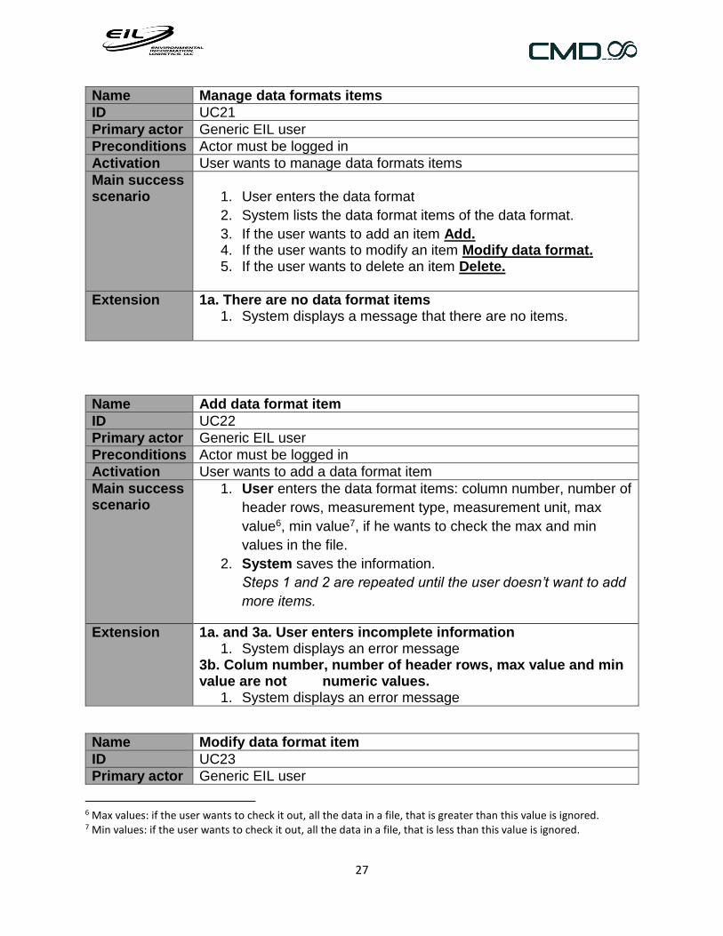
Name Manage data formats items
ID UC21
Primary actor Generic EIL user
Preconditions Actor must be logged in
Activation User wants to manage data formats items
Main success scenario
1. User enters the data format
2. System lists the data format items of the data format.
3. If the user wants to add an item Add. 4. If the user wants to modify an item Modify data format. 5. If the user wants to delete an item Delete.
Extension 1a. There are no data format items 1. System displays a message that there are no items.
Name Add data format item
ID UC22
Primary actor Generic EIL user
Preconditions Actor must be logged in
Activation User wants to add a data format item
Main success scenario
1. User enters the data format items: column number, number of
header rows, measurement type, measurement unit, max
value6, min value7, if he wants to check the max and min
values in the file.
2. System saves the information.
Steps 1 and 2 are repeated until the user doesn’t want to add
more items.
Extension 1a. and 3a. User enters incomplete information 1. System displays an error message
3b. Colum number, number of header rows, max value and min value are not numeric values.
1. System displays an error message
Name Modify data format item
ID UC23
Primary actor Generic EIL user
6 Max values: if the user wants to check it out, all the data in a file, that is greater than this value is ignored. 7 Min values: if the user wants to check it out, all the data in a file, that is less than this value is ignored.

28
Preconditions Actor must be logged in
Activation User wants to modify a data format item
Main success scenario
1. User enters the data format he wants to modify.
2. System displays the name of the data format, type of file and
items: column number, number of header rows, measurement
type, measurement unit, max value8, min value9, if he wants
to check the max and min values in the file.
3. User edits the information.
Steps 2 and 3 are repeated until the user doesn’t want to
modify more items.
Extension 3a. User enters incomplete information 1. System displays an error message
3b. Colum number, number of header rows, max value and min value are not numeric values.
1. System displays an error message
Name Delete data format item
ID UC24
Primary actor Generic EIL user
Preconditions Actor must be logged in
Activation User wants to delete a data format item
Main success scenario
1. User enters a data format item
2. System deletes the data format item.
Steps 1 and 2 are repeated until the user doesn’t want to
delete more items.
Extension
Name Manage FTP Server
ID UC29
Primary actor Generic EIL user
Preconditions Actor must be logged in
Activation User wants to manage ftp server configurations.
Main success scenario
1. User enters a client
8 Max values: if the user wants to check it out, all the data in a file, that is greater than this value is ignored. 9 Min values: if the user wants to check it out, all the data in a file, that is less than this value is ignored.

29
2. System presents the sites of the selected client, which the
user has permissions to.
3. User enters a site.
4. System presents Ftp servers of the entered site
5. If user wants to add a server Add FTP server. 6. If user wants to modify a server Modify FTP server. 7. If user wants to delete a server Delete FTP server. 8. If user wants to add, modify or delete a folder path, go to
Folder paths.
Extension 2a. There are no sites. 1. System displays a message that there are no sites for the
selected client. 2. The use case ends
2b. User doesn’t have permissions to any site 1. System displays a message that there aren’t permitted sites
for the selected client. 2. The use case ends
Name Add a FTP Server
ID UC30
Primary actor Generic EIL user
Preconditions Actor must be logged in
Activation User wants to add a ftp server configuration.
Main success scenario
1. User enters the server name, folder, username and
password. 2. System saves the information, test the connection and
displays a success message.
Extension 2a. User enters incomplete information. 1. System displays an error message. 2. Go back to step 1 of the main scenario.
2b. The connection to the server fails 1. System displays an error message
Name Modify FTP Server
ID UC31
Primary actor Generic EIL user
Preconditions Actor must be logged in
Activation User wants to modify a ftp server configuration
Main success scenario
1. User enters the ftp server configuration he wants to modify.

30
2. System presents the server name,, username and password of the selected server.
3. User edits the information. 4. System saves the information, test the connection and
displays a success message.
Extension 4b The connection to the server fails 1. System displays an error message
Name Delete FTP Server configuration
ID UC32
Primary actor Generic EIL user
Preconditions Actor must be logged in
Activation User wants to delete a ftp server configuration
Main success scenario
1. User enters the configuration he wants to delete. 2. System deletes the configuration selected and displays a
success message.
Extension 2a. There are Ftp download schedules associate to the entered server
1. System displays a message, that there are Ftp download schedules associate to the entered server and gives the option to edit them or delete them.
Name Add a folder path to a FTP Server configuration
ID UC33
Primary actor Generic EIL user
Preconditions Actor must be logged in
Activation User wants to add a folder path of a ftp server configuration
Main success scenario
1. User enters a new path. 2. System saves the new path, and checks if the folder path
exists. Steps 1 to 2 are repeated until the user doesn’t want to add more paths.
Extension 2a. User enters incomplete information. 1. System displays an error message.
2b. The new path doesn’t exists 1. System displays an error message.
31
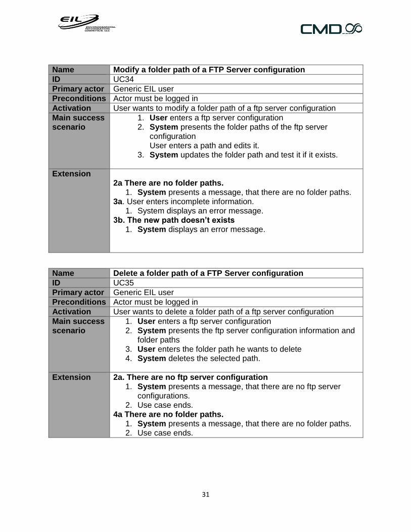
Name Modify a folder path of a FTP Server configuration
ID UC34
Primary actor Generic EIL user
Preconditions Actor must be logged in
Activation User wants to modify a folder path of a ftp server configuration
Main success scenario
1. User enters a ftp server configuration 2. System presents the folder paths of the ftp server
configuration User enters a path and edits it.
3. System updates the folder path and test it if it exists.
Extension 2a There are no folder paths.
1. System presents a message, that there are no folder paths. 3a. User enters incomplete information.
1. System displays an error message. 3b. The new path doesn’t exists
1. System displays an error message.
Name Delete a folder path of a FTP Server configuration
ID UC35
Primary actor Generic EIL user
Preconditions Actor must be logged in
Activation User wants to delete a folder path of a ftp server configuration
Main success scenario
1. User enters a ftp server configuration 2. System presents the ftp server configuration information and
folder paths 3. User enters the folder path he wants to delete 4. System deletes the selected path.
Extension 2a. There are no ftp server configuration 1. System presents a message, that there are no ftp server
configurations. 2. Use case ends.
4a There are no folder paths. 1. System presents a message, that there are no folder paths. 2. Use case ends.

32
2.1.3.2 Data Entry
Name Manage FTP download schedule
ID UC36
Primary actor Generic EIL user
Preconditions Actor must be logged in
Activation User wants to manage ftp download schedules
Main success scenario
1. User enters a client
2. System presents the sites of the selected client, which the
user has permissions to.
3. User enters a site.
4. System presents Ftp download schedules of the entered site
5. If user wants to add a schedule Add FTP download schedule.
6. If user wants to modify a schedule Modify FTP download schedule.
7. If user wants to delete a schedule Delete FTP download schedule
uc Data Entry
Manual Entry (add,
delete, modify)
Scheduling ftp
download
(add,edit,delete)
Upload data from a
single file
EIL generic user
Manual ftp download
Clock
Download FTP files
Upload file
Manage FTP
download schedule «include»
«extend»
«extend»
«extend»

33
Extension
2a. There are no sites. 3. System displays a message that there are no sites for the
selected client. 4. The use case ends
2b. User doesn’t have permissions to any site 3. System displays a message that there aren’t permitted sites
for the selected client. 4. The use case ends.
Name Add FTP download schedule
ID UC37
Primary actor Generic EIL user
Preconditions Actor must be logged in
Activation User wants to add a ftp download schedule
Main success scenario
1. System presents the reportable units of the site, which the
user has permissions to.
2. User enters a reportable unit
3. System presents the file templates and data loggers of the reportable unit.
4. User enters a file templates, data logger, Ftp server configuration and a folder path, file note10, time shift11, time frame12: start time and end date, recurrence pattern (Daily, Weekly and Monthly).
5. System saves the schedule, displays a success message.
Extension
1a. There are no reportable units. 1. System displays a message that there are no reportable units
for the selected client. 2. The use case ends
1b. User doesn’t have permissions to reportable unit 1. System displays a message that there aren’t permitted
reportable units for the selected site. 2. The use case ends
4a.There are no file templates 1. System displays a message that there are no file templates
for the selected reportable unit. 2. The use case ends
4a.There are no data loggers
10 A file can have an explanation of its content. 11 A user can add or subtract hours to the time stamp of the data, in order to change its time zone. 12 The time frame is the date range, where the files where created (one by day).

34
1. System displays a message that there are no data loggers for the selected reportable unit.
2. The use case ends 6a. There are no ftp servers
1. System displays a message that there are no ftp servers configured. The system suggest the user to add a new configuration.
2. User case ends. 6b. User entered a weekly recurrence pattern
1. System presents the days of the week 6c. User entered a monthly recurrence patter.
1. System presents the days of a month 6d. User enters incomplete information.
1. System displays an error message. 2. Go back to step 1 of the main scenario.
6e. Start date is > end date or they are invalid. 1. System displays an error message. 2. Go back to step 14 of the main scenario.
Name Modify FTP download schedule
ID UC38
Primary actor Generic EIL user
Preconditions User must be logged in
Activation User wants to modify a ftp download schedule
Main success scenario
1. User enters the schedule he wants to modify. 2. System presents the information of the selected schedule:
data format, data logger, ftp server, ftp files path, start and end date, recurrence patter, file note and time shift.
3. User edits the information. 4. System saves the information.
Extension 3a. User entered a weekly recurrence pattern 1. System presents the days of the week
3b. User entered a monthly recurrence patter. 1. System presents the days of a month
3c. User enters incomplete information. 1. System displays an error message. 2. Go back to step 1 of the main scenario.
3d. Start date is > end date or they are invalid. 1. System displays an error message. 2. Go back to step 14 of the main scenario.

35
Name Delete FTP download schedule
ID UC39
Primary actor Generic EIL user
Preconditions Actor must be logged in
Activation User wants to delete a ftp download schedule
Main success scenario
1. User enters the schedule he wants to delete. 2. System deletes the selected schedule.
Extension 1a There are no schedules. 1. System presents a message that there are no schedules 2. User case ends
Name Download ftp files
ID UC40
Primary actor Clock
Preconditions The time on the clock is correct. There is a ftp download schedule for the current timestamp.
Activation Clock indicates it’s time to download files from a ftp server.
Main success scenario
1. System connects to the selected ftp server and downloads the files according to the dates and recurrence pattern indicated. Then those files are uploaded to the data base.
2. User receives a confirmation email of every file transferred indicating success of the transfer
Extension 1a. There is an error downloading the files 1. System sends an email to the user explaining the error.
Name Manual FTP download
ID UC41
Primary actor Generic EIL user
Preconditions Actor must be logged in
Activation User wants to schedule a ftp download of files to be uploaded in the flare data base.
Main success scenario
1. User enters a client
2. System presents the sites of the selected client, which the
user has permissions to.
3. User enters a site.
4. System presents the reportable units of the site, which the
user has permissions to.
5. User enters a reportable unit.

36
6. System presents the file templates and data loggers of the
reportable unit.
7. User enters a file templates, data logger, Ftp server configuration and a folder path, file note13, time shift14, time frame15: start and end.
8. System validates the information, connects to the selected ftp server and downloads the files to the dates indicated. Then those files are uploaded to the data base.
9. User receives a confirmation email of every file transferred indicating success of the transfer.
Extension 2a. There are no sites. 1. System displays a message that there are no sites for the
selected client. 2. The use case ends
2b. User doesn’t have permissions to any site 1. System displays a message that there aren’t permitted sites
for the selected client. 2. The use case ends
2a. There are no reportable units. 1. System displays a message that there are no reportable units
for the selected client. 2. The use case ends
2b. User doesn’t have permissions to reportable unit 1. System displays a message that there aren’t permitted
reportable units for the selected site. 2. The use case ends
6a.There are no file templates 1. System displays a message that there are no file templates
for the selected reportable unit. 2. The use case ends
6a.There are no data loggers 1. System displays a message that there are no data loggers for
the selected reportable unit. 2. The use case ends
9a. User enters incomplete information. 3. System displays an error message. 4. Go back to step 1 of the main scenario.
9b. Start and end dates are invalid or start date > end date. 1. System displays an error message. 2. Go back to step 14 of the main scenario.
10a. There is a failure in the download and transfer
13 A file can have an explanation of its content. 14 A user can add or subtract hours to the time stamp of the data, in order to change its time zone. 15 The time frame is the range where the files where created (one by day).

37
1. System sends an email to the user explaining the error.
Name Upload data from a single file
ID UC42
Primary actor Generic EIL user
Preconditions Actor must be logged in
Activation User wants to upload a data file.
Main success scenario
1. User enters a client
2. System presents the sites of the selected client, which the
user has permissions to.
3. User enters a site.
4. System presents the reportable units of the site, which the
user has permissions to.
5. User enters a reportable unit.
6. System presents the file templates and data loggers of the
reportable unit.
7. User enters a file template, data logger, time shift, file note
and the file.
8. System validates the data, uploads it and sends a
confirmation email attaching a copy of the file and a report of
the process indicating success.
Extension 2a. There are no sites. 1. System displays a message that there are no sites for the
selected client. 2. The use case ends
2b. User doesn’t have permissions to any site 1. System displays a message that there aren’t permitted sites
for the selected client. 2. The use case ends
2a. There are no reportable units. 1. System displays a message that there are no reportable units
for the selected client. 2. The use case ends
2b. User doesn’t have permissions to reportable unit 1. System displays a message that there aren’t permitted
reportable units for the selected site. 2. The use case ends
6a.There are no file templates 1. System displays a message that there are no file templates
for the selected reportable unit. 2. The use case ends

38
6a.There are no data loggers 1. System displays a message that there are no data loggers for
the selected reportable unit. 2. The use case ends
7a. User enters incomplete information. 1. System displays an error message. 2. Go back to step 1 of the main scenario.
Name Upload file
ID UC43
Primary actor
Preconditions
Activation
Main success scenario
1. System validates the data.
2. System upload the data and sends a confirmation email
attaching a copy of the file and a report of the process indicating
success.
Extension 1a. There is Duplicated data in the file 1. System writes the duplicated data on the file report as
“duplicated data” and sends an email attaching the report, the file and indicating failure.
2. User case ends 1b. The data in the file is already in the data base
1. System writes the duplicated data on the file report as “rejected lines”16.
2. Go to step 2 in the main scenario
1c. A column specified in the data format, doesn’t exist on the file.
1. System writes on the file report as “error” what column doesn’t exist and sends an email indicating failure.
2. User case ends. 1d. The timestamp format in the lines of the file doesn’t match the data format’s date format.
1. System writes on the file report as “errors” what timestamps doesn’t match the date format and sends an email, attaching the report and the file indicating failure.
16 The uploading file process report, shows the rejected lines of the file. These rejected lines are the duplicated data found between the data base and the file.

39
2. Use case ends 1e. A data value in the file is not a number.
1. System checks for illegal expression specified for that reportable unit. 1e.1 The value is an illegal expression
a. It is written in the report file as “rejected lines”. b. Go to step 2 in the main scenario
1e.2 The value is not an illegal expression a. It’s written on the file report as “errors” and an email is
sent indicating failure. b. User case ends
1f. There is a line in the file without timestamp 1. System writes the line on the file report as “errors” and send
an email, attaching the report and the file indicating failure. 2. Use case ends.
Name List manual entries
ID UC44
Primary actor Generic EIL user
Preconditions Actor must be logged in
Activation User wants to list manual data entries.
Main success scenario
1. User enters a client
2. System presents the sites of the selected client, which the
user has permissions to.
3. User enters a site.
4. System presents the reportable units of the site, which the
user has permissions to.
5. User enters a reportable unit and the time frame.
6. System presents the manual data entries.
7. If the user wants to add a data entry Add data entry. 8. If the user wants to modify a data entry Modify data entry. 9. If the user wants to delete a data entry Delete data entry.
Extension 1a. There are no clients 1. System displays a message that there are no clients.
2a. There are no sites. 1. System displays a message that there are no sites for the
entered client. 2. The use case ends
2b. User doesn’t have permissions to any site 1. System displays a message that there aren’t permitted sites
for the entered client.

40
2. The use case ends 4a. There are no reportable units.
1. System displays a message that there are no reportable units for the entered client.
2. The use case ends 4b. User doesn’t have permissions to reportable unit
3. System displays a message that there aren’t permitted reportable units for the entered site.
4. The use case ends 6a. There are no manual data entries
2. System displays a message that there are no data entries.
Name Add manual entry
ID UC45
Primary actor Generic EIL user
Preconditions Actor must be logged in
Activation User wants to add a manual entry
Main success scenario
1. User enters a date, data value, measurement unit,
measurement type and a data logger. 2. System saves the information and displays a success
message
Extension 1a. User enters incomplete information 1. System displays an error message.
1b. Data Value is not a numeric value. 1. System displays an error message.
1c. The entered date is not a valid date 1. System displays an error message.
Name Modify manual entry
ID UC46
Primary actor Generic EIL user
Preconditions Actor must be logged in
Activation User wants to modify a manual entry
Main success scenario
1. User enters a data entry 2. System show the information of the entered data entry. 3. User edits the information. 4. System updated the information and displays a success
message.

41
Extension 3a. User enters incomplete information
1. System displays an error message. 3b. Data Value is not a numeric value.
1. System displays an error message. 3c. The entered date is not a valid date
1. System displays an error message.
Name Delete manual entry
ID UC47
Primary actor Generic EIL user
Preconditions Actor must be logged in
Activation User wants to delete a manual entry
Main success scenario
1. User enters the data entry he wants to delete 2. System deletes the data entry.
Extension
2.1.3.3 Data Deletion
uc Data Deletion
Data deleletion by file
EIL Admin
Data deletion by time
frame
Large Block Data
Deletion
Delete Duplicated
Data

42
Name Data deletion by file
ID UC25
Primary actor EIL admin user
Preconditions Actor must be logged in
Activation User wants to delete a file.
Main success scenario
1. User enters a client
2. System presents all the sites of the selected client.
3. User enters a site.
4. System presents all the reportable units of the site.
5. User enters a reportable unit.
6. System presents the files of the reportable unit uploaded in
the entered time frame.
7. User enters the file he wants to delete.
8. System deletes the file and displays a success message.
Extension 2a. There are no sites. 1. System displays a message that there are no sites for the
selected client. 2. The use case ends
4a. There are no reportable units. 1. System displays a message that there are no reportable units
for the selected site. 2. The use case ends
5a The from date is > than the to date or they are invalid 1. System displays an error message
Name Data deletion by time frame
ID UC26
Primary actor EIL admin user
Preconditions Actor must be logged in
Activation User wants to delete a set of data searching by time frame.
Main success scenario
1. User enters a client
2. System presents all the sites of the selected client.
3. User enters a site.
4. System presents all the reportable units of the site.
5. User enters a reportable unit
6. System presents the measurement types the reportable unit
keeps track of
7. User enters a measurement type and the time frame of the
data.

43
8. System presents the timestamp, time zone, the measurement
unit, value, of every data point in the selected time frame and
reportable unit.
9. User enters the data points he wants to delete.
10. System deletes the data and displays a success message.
Extension 2a. There are no sites. 1. System displays a message that there are no sites for the
selected client. 2. The use case ends
4a. There are no reportable units. 1. System displays a message that there are no reportable units
for the selected site. 2. The use case ends
6a. The reportable unit doesn’t keep track of any measurement type.
1. System displays a message that there are no measurement types for the entered reportable unit.
2. The use case ends 7a The from date is > than the to date or they are invalid
1. System displays an error message
Name Large block data deletion
ID UC27
Primary actor EIL admin user
Preconditions Actor must be logged in
Activation User wants to delete a large block of data
Main success scenario
1. User enters a client
2. System presents all the sites of the selected client.
3. User enters a site.
4. System presents all the reportable units of the site.
5. User enters a reportable unit
6. System presents the measurement types the reportable unit
keeps track of
7. User enters a measurement type and the time frame of the
data.
8. System deletes the data of the entered reportable unit and
time frame.
Extension 2a. There are no sites.

44
1. System displays a message that there are no sites for the selected client.
2. The use case ends 4a. There are no reportable units.
1. System displays a message that there are no reportable units for the selected site.
2. The use case ends 6a. The reportable unit doesn’t keep track of any measurement type.
1. System displays a message that there are no measurement types for the entered reportable unit.
2. The use case ends 7a The from date is > than the to date or they are invalid
1. System displays an error message
Name Delete duplicated data
ID UC28
Primary actor EIL admin user
Preconditions Actor must be logged in
Activation User wants to delete a large block of data
Main success scenario
1. User enters a client
2. System presents all the sites of the selected client.
3. User enters a site.
4. System presents all the reportable units of the site.
5. User enters a reportable unit
6. System presents the measurement types the reportable unit
keeps track of
7. User enters a measurement type and the time frame of the
data.
8. System presents the duplicated data 17 in the entered
reportable unit and time frame.
9. User enters the data he wants to delete.
10. System deletes the data and displays a success message.
Extension 2a. There are no sites. 1. System displays a message that there are no sites for the
selected client. 2. The use case ends
4a. There are no reportable units.
17 Duplicated data: data with the same timestamp, data value, measurement type and unit or data with the same timestamp, measurement type and unit but different data value.

45
1. System displays a message that there are no reportable units for the selected site.
2. The use case ends 6a. The reportable unit doesn’t keep track of any measurement type.
1. System displays a message that there are no measurement types for the entered reportable unit.
2. The use case ends 7a The from date is > than the to date or they are invalid
1. System displays an error message

46
2.1.3.4 Administration
Name Manage user
ID UC65
Primary actor EIL admin user
Preconditions Actor must be logged in
uc Administration
Ilegal Expressions (add)
Change password
User (add,
modify,delete)
User permissions
(add, delete)
Data Base Statistics
Report
See log file
EIL Admin
Eil generic user
Client
Ilegal Expressions
(delete)
Ilegal Expressions
(modify)
Ilegal Expressions
site (add, delete)
Manage users
Manage permissions
«extend»
«extend»
«include»
«include»

47
Activation User wants to manage a user
Main success scenario
1. System displays all the users of the application 2. If the user wants to add a user Add User 3. If the user wants to modify a user Modify user. 4. If the user wants to delete a user Delete user.
Extension 1a. There are no users 1. System displays a message that there are no users.
Name Add user
ID UC66
Primary actor EIL admin user
Preconditions Actor must be logged in
Activation User wants to add a user
Main success scenario
5. User enters username, password, email, user type (Client, EIL, EIL admin)
6. System saves the information, creates the new user and displays a success message.
Extension 1a. User entered incomplete information 2. System displays an error message.
Name Modify user
ID UC67
Primary actor EIL admin user
Preconditions Actor must be logged in
Activation User wants to modify a user
Main success scenario
1. User enters the user he wants to modify 2. System displays username, password, email, user type
(Client, EIL, EIL admin). 3. User modifies the information 4. System updates the information and displays a success
message.
Extension 3a. User entered incomplete information System displays an error message.
Name Delete user
ID UC68
Primary actor EIL admin user
Preconditions Actor must be logged in
Activation User wants to delete a user
Main success scenario
1. User enters the user he wants to delete 2. System deletes the user entered.

48
Name Manage permissions
ID UC69
Primary actor EIL admin user
Preconditions Actor must be logged in
Activation User wants to manage a permission
Main success scenario
1. User enters the user he wants to see his permissions 2. System displays all the users of the application 3. If the user wants to add a permission Add permission 4. If the user wants to delete a permission Delete permission.
Extension 2a. There are no permissions 1. System displays a message that there are no permissions for
the selected user.
Name Add user permission
ID UC7
Primary actor EIL admin user
Preconditions Actor must be logged in
Activation User wants to add a permission to a user
Main success scenario
1. System presents all the sites.
2. User enters a site.
3. System presents all the reportable units of the site.
4. User enters one or more reportable units
Steps 2 to 4 are repeated until the user doesn’t want to add
more sites.
Extension 2a. There are no sites. 1. System displays a message that there are no sites for the
selected client. 2. The use case ends
4a. There are no reportable units. 1. System displays a message that there are no reportable units
for the selected site.
Name Delete user permission
ID UC71
Primary actor EIL admin user
Preconditions Actor must be logged in
Activation User wants to add a permission to a user
Main success scenario
1. System presents all the permission of a user. 2. User enters the permission he wants to delete.

49
3. System deletes the permission.
Extension 1a. User doesn’t have permissions 1. System displays a message that there are no permissions for
the entered user.
Name Add illegal expression
ID UC72
Primary actor EIL Admin user
Preconditions Actor must be logged in
Activation User wants to see the add an illegal expression file
Main success scenario
1. User enters a new illegal expression 2. System saves the new illegal expression 3. User enters the site, which its files can contain the
expression. 4. System saves the site.
Steps 3 to 4 are repeated until the user doesn’t want to add more sites.
Extension
Name Modify Illegal expression
ID UC73
Primary actor EIL Admin user
Preconditions Actor must be logged in
Activation User wants to see the add an illegal expression file
Main success scenario
1. User enters the illegal expression he wants to modify 2. System presents the illegal expression and its sites 3. User modifies it. 4. System saves the information
Extension 3a User enters incomplete information 1. System displays an error message.
Name Delete illegal expression
ID UC74
Primary actor EIL Admin user
Preconditions Actor must be logged in
Activation User wants to see the add an illegal expression file
Main success scenario
1. User enters the illegal expression he wants to delete 2. System deletes the illegal expression
Extension
Name Illegal expression add site

50
ID UC75
Primary actor EIL Admin user
Preconditions Actor must be logged in
Activation User wants to see the add a site to an illegal expression
Main success scenario
1. System presents all the sites 2. User enters a site 3. System saves the new site
Steps 1 to 3 are repeated until the user doesn’t want to add more sites.
Extension 1a. There are no sites. 1. System displays a message that there are no sites for the
selected client. 2. The use case ends
Name Illegal expression delete site
ID UC76
Primary actor EIL Admin user
Preconditions Actor must be logged in
Activation User wants to see the delete a site from an illegal expression
Main success scenario
1. System presents all the sites of the illegal expression 2. User enters the site he wants to delete 3. System deletes the user
Extension 1a. There are no sites. 1. System displays a message that there are no sites for the
selected client. 2. The use case ends
Name See log file
ID UC77
Primary actor EIL generic user, client
Preconditions Actor must be logged in
Activation User wants to see the log file
Main success scenario
1. System presents the log file in txt.
Extension
Name Change password

51
ID UC78
Primary actor EIL generic user, client
Preconditions Actor must be logged in
Activation User wants to change his password
Main success scenario
1. User enters the old password, new password, confirmation of the new password
2. System updates the password.
Extension 1a The old and new passwords are equal 1. System displays an error message
1a. new password and its confirmation are equal 1. System displays an error message
Name Data base statistics report
ID UC79
Primary actor EIL admin user
Preconditions Actor must be logged in
Activation User wants to add a permission to a user
Main success scenario
1. User wants to run a data base statistics report. 2. System presents a pdf file with the report.
Extension
2.1.3.5 Flow reports
uc Flow Report
Av erage Max Min Flow reports (Daily,
weekly, monthly, yearly)
Flow Reports
(Daily,weekly,monthly,yearly)
Daily Back Weighted
Flow Report
Generic user
52
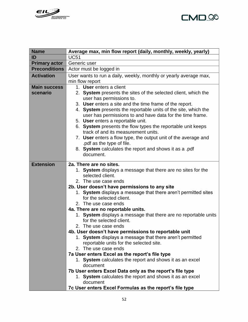
Name Average max, min flow report (daily, monthly, weekly, yearly)
ID UC51
Primary actor Generic user
Preconditions Actor must be logged in
Activation User wants to run a daily, weekly, monthly or yearly average max, min flow report
Main success scenario
1. User enters a client 2. System presents the sites of the selected client, which the
user has permissions to. 3. User enters a site and the time frame of the report. 4. System presents the reportable units of the site, which the
user has permissions to and have data for the time frame. 5. User enters a reportable unit. 6. System presents the flow types the reportable unit keeps
track of and its measurement units. 7. User enters a flow type, the output unit of the average and
.pdf as the type of file. 8. System calculates the report and shows it as a .pdf
document.
Extension 2a. There are no sites. 1. System displays a message that there are no sites for the
selected client. 2. The use case ends
2b. User doesn’t have permissions to any site 1. System displays a message that there aren’t permitted sites
for the selected client. 2. The use case ends
4a. There are no reportable units. 1. System displays a message that there are no reportable units
for the selected client. 2. The use case ends
4b. User doesn’t have permissions to reportable unit 1. System displays a message that there aren’t permitted
reportable units for the selected site. 2. The use case ends
7a User enters Excel as the report’s file type 1. System calculates the report and shows it as an excel
document 7b User enters Excel Data only as the report’s file type
1. System calculates the report and shows it as an excel document
7c User enters Excel Formulas as the report’s file type

53
1. System calculates the report and shows it as an excel document with embedded formulas.
Explanation This report takes all the data of the entered reportable unit and flow type, calculating the average, maximum and minimum value in the time frame or every day, week, month or year in the time period. It shows the client, site and the name of the reportable unit, average, maximum and minimum value and its timestamp for every day, week, month or year in the time frame.
Name Flow reports (daily, monthly, weekly, yearly)
ID UC50
Primary actor Generic user
Preconditions Actor must be logged in
Activation User wants to run a daily, weekly, monthly or yearly Flow report
Main success scenario
1. User enters a client 2. System presents the sites of the selected client, which the
user has permissions to.
3. User enters a site and the time frame of the report.
4. System presents the reportable units of the site, which the
user has permissions to and have data for the time frame.
5. User enters a reportable unit.
6. System presents the flow types the reportable unit keeps
track of and its measurement units.
7. User enters a flow type, the output unit of the flow volume
and flow rate, time between records, low flow threshold,
runtime (days, hours or minutes), the max and min values is
inactive and PDF as the type of file. The user doesn’t want to
save the current setting.
8. System calculates the report and shows it as a pdf document.
Extension 2a. There are no sites. 1. System displays a message that there are no sites for the
selected client. 2. The use case ends
2b. User doesn’t have permissions to any site 1. System displays a message that there aren’t permitted sites
for the selected client. 2. The use case ends
4a. There are no reportable units. 1. System displays a message that there are no reportable units
for the selected client. 2. The use case ends

54
4b. User doesn’t have permissions to reportable unit 1. System displays a message that there aren’t permitted
reportable units for the selected site. 2. The use case ends
7a User enters Excel as the report’s file type 1. System calculates the report and shows it as an excel
document 7b User enters Excel Data only as the report’s file type
1. System calculates the report and shows it as an excel document
7c the max and min values is activated 1. The data taken to calculate the report is the average of the
max and min values of the entered flow type. 7c .1a.There is not data for either the max or the min flow type. i) System displays a message, that there is no data. ii) User case ends
7d User wants to save the current setting. 1. System saves the setting of the report (output unit of the flow
volume and flow rate, time between records, low flow threshold, runtime and type of file) for the next time the user wants to run a report.
7e There is data in CFM or m3/min units. 1. System ask for reference information 2. User enters reference pressure and its units, temperature
standard (20,25 Celsius degrees) and reference temperature and its units,
3. System converts the data from CFM to SCFM.
Explanation The Daily, Weekly, Monthly and Yearly flow reports calculates the total flow, the average flow rate and the runtime for the selected time period. The way that the flow report calculates the total flow volume consists on summing (per day or week or month or year) the average of every two consecutive flow data points times the time that separates them. In order to calculate, this must be neither missing data nor flow less that the threshold value. For example, we have 700 SCFM at 15:10, 755 SCFM at 15:20 and 760 SCFM at 15:30 in a day, so the total flow of the day is ((700+755)/2 * 10 minutes) + ((755+760)/2 * 10 minutes) =15,150 SFC. Finally, the runtime value is equal to the time the flow is present and the flow rate is equals to the flow volume divided by the flow rate. Following the last example the runtime in that day is 20 minutes and the flow rate is 757.5 SCFM.
Name Daily back weighed flow report
ID UC52
Primary actor Generic user
Preconditions Actor must be logged in

55
Activation User wants to run a Daily back weighed flow report
Main success scenario
1. User enters a client 2. System presents the sites of the selected client, which the
user has permissions to.
3. User enters a site and the time frame of the report.
4. System presents the reportable units of the site, which the
user has permissions to and have data for the time frame.
5. User enters a reportable unit.
6. System presents the flow types the reportable unit keeps
track of and its measurement units.
9. User enters a flow type, the output unit of the flow volume
and flow rate, time between records (days, hours, minutes),
low flow threshold, the max and min values is inactive,
runtime (days, hours or minutes) and PDF as the type of file.
The user doesn’t want to save the current setting.
7. System calculates the report and shows it as a pdf document.
Extension 2a. There are no sites. 1. System displays a message that there are no sites for the
selected client. 2. The use case ends
2b. User doesn’t have permissions to any site 1. System displays a message that there aren’t permitted sites
for the selected client. 2. The use case ends
4a. There are no reportable units. 1. System displays a message that there are no reportable units
for the selected client. 2. The use case ends
4b. User doesn’t have permissions to reportable unit 1. System displays a message that there aren’t permitted
reportable units for the selected site. 2. The use case ends
7a User enters Excel as the report’s file type 1. System calculates the report and shows it as an excel
document 7b User enters Excel Data only as the report’s file type
1. System calculates the report and shows it as an excel document
7c the max and min values is activated 1. The data taken to calculate the report is the average of the
max and min values of the entered flow type. 7c .1a.There is not data for either the max or the min flow type.

56
i) System displays a message, that there is no data. ii) User case ends
7d User wants to save the current setting. 1. System saves the setting of the report (output unit of the flow
volume and flow rate, time between records, low flow threshold, runtime and type of file) for the next time the user wants to run a report.
Explanation This report takes all the data of the entered reportable unit and flow type, calculating the flow volume, runtime and flow rate of every day, week, month or year in the time frame. The data is presented in the entered output units.
2.1.3.6 Operating reports
Name Uptime down time report (daily, monthly, weekly, yearly)
ID UC53
Primary actor Generic user
Preconditions Actor must be logged in
Activation User wants to run a daily, weekly, monthly or yearly uptime downtime report
Main success scenario
1. User enters a client 2. System presents the sites of the selected client, which the
user has permissions to.
3. User enters a site and the time frame of the report.
4. System presents the reportable units of the site, which the
user has permissions to and have data for the time frame.
5. User enters a reportable unit.
6. System presents the flow and temperature types, which the
reportable unit keeps track of and its measurement units
10. User enters a flow or temperature type and its output unit,
time between records (days, hours, minutes), low flow
uc Operating Reports
Uptime Downtime Reports
(Daily,weekly,monthly,yearly)
Venting report
Generic user
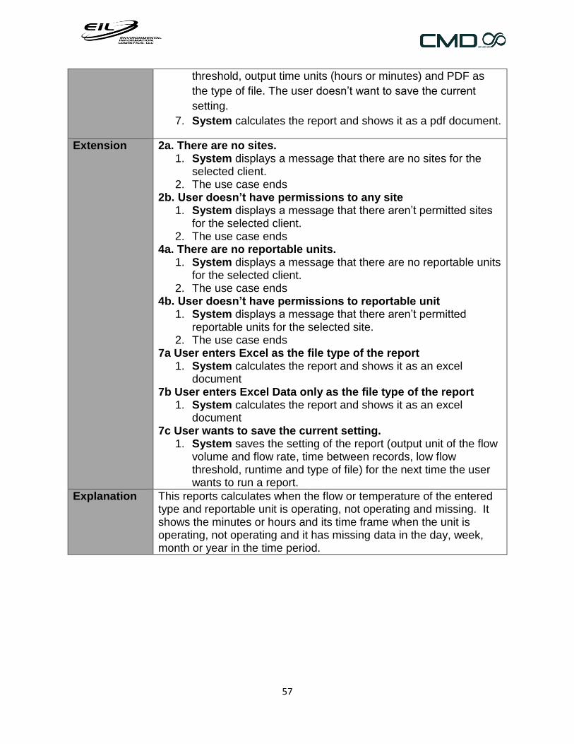
57
threshold, output time units (hours or minutes) and PDF as
the type of file. The user doesn’t want to save the current
setting.
7. System calculates the report and shows it as a pdf document.
Extension 2a. There are no sites. 1. System displays a message that there are no sites for the
selected client. 2. The use case ends
2b. User doesn’t have permissions to any site 1. System displays a message that there aren’t permitted sites
for the selected client. 2. The use case ends
4a. There are no reportable units. 1. System displays a message that there are no reportable units
for the selected client. 2. The use case ends
4b. User doesn’t have permissions to reportable unit 1. System displays a message that there aren’t permitted
reportable units for the selected site. 2. The use case ends
7a User enters Excel as the file type of the report 1. System calculates the report and shows it as an excel
document 7b User enters Excel Data only as the file type of the report
1. System calculates the report and shows it as an excel document
7c User wants to save the current setting. 1. System saves the setting of the report (output unit of the flow
volume and flow rate, time between records, low flow threshold, runtime and type of file) for the next time the user wants to run a report.
Explanation This reports calculates when the flow or temperature of the entered type and reportable unit is operating, not operating and missing. It shows the minutes or hours and its time frame when the unit is operating, not operating and it has missing data in the day, week, month or year in the time period.

58
2.1.3.7 Query reports
Name Multiple units data report (1-10 reportable units)
ID UC56
Primary actor Generic user
Preconditions Actor must be logged in
Activation User wants to run a multiple units data report (1-10 reportable units)
Main success scenario
1. User enters a client 2. System presents the sites of the selected client, which the
user has permissions to.
3. User enters a site and the time frame of the report.
4. System presents the reportable units of the site, which the
user has permissions to.
5. User enters a reportable unit
6. System presents the measurement types the reportable unit
keeps track of and its measurement units.
7. User enters a measurement type and unit.
Steps 4 to 7 are repeated until the user doesn’t want to add
more reportable units or has completed 10 reportable units.
8. System calculates the report and shows it as a pdf document.
Extension 2a. There are no sites. 1. System displays a message that there are no sites for the
selected client. 2. The use case ends
uc Query report
Multiple units data report (1-10
reportable units)
Data report
Data Chart
Generic user

59
2b. User doesn’t have permissions to any site 1. System displays a message that there aren’t permitted sites
for the selected client. 2. The use case ends
4a. There are no reportable units. 1. System displays a message that there are no reportable units
for the selected client. 2. The use case ends
4b. User doesn’t have permissions to reportable unit 1. System displays a message that there aren’t permitted
reportable units for the selected site. 2. The use case ends
6a There are no measurement types 1. System displays message that there aren’t the reportable
unit’s measurement types. 2. Go back to step 4 in the main scenario.
8a User enters Excel as the file type of the report. 1. System calculates the report and shows it as an excel
document 8b User enters Excel Data only as the file type of the report.
1. System calculates the report and shows it as an excel document
Explanation This report shows the data of a given time frame, reportable units and measurement types, presented in the entered units. One column is the timestamp and the other is the data of the first reportable unit and so on.
Name Data report
ID UC55
Primary actor Generic user
Preconditions Actor must be logged in
Activation User wants to run a data report
Main success scenario
1. User enters a client 2. System presents the sites of the selected client, which the
user has permissions to.
3. User enters a site and the time frame of the report.
4. System presents the reportable units of the site, which the
user has permissions to and have data for the time frame.
5. User enters a reportable unit.
6. System presents the measurement types, which the
reportable unit keeps track of.

60
7. User enters one or two measurement types, a data logger,
type of document (pdf, excel, excel data only) and how he
wants to sort the results
8. System shows a pdf file with the report.
Extension 2a. There are no sites. 1. System displays a message that there are no sites for the
selected client. 2. The use case ends
2b. User doesn’t have permissions to any site 1. System displays a message that there aren’t permitted sites
for the selected client. 2. The use case ends
4a. There are no reportable units. 1. System displays a message that there are no reportable units
for the selected client. 2. The use case ends
4b. User doesn’t have permissions to reportable unit 1. System displays a message that there aren’t permitted
reportable units for the selected site. 2. The use case ends
6a There are no measurement types 1. System displays message that there aren’t the reportable
unit’s measurement types. 2. Use case ends.
7a User enters Excel as the file type of the report 1. System calculates the report and shows it as an excel
document 7b User enters Excel Data only as file type of the report
1. System calculates the report and shows it as an excel document
7c user entered none data loggers 1. System presents the data of all data loggers of the reportable
unit.
Explanation This report presents the data of the entered measurement type, reportable unit and data logger in the time frame. This data is sorted by date ascending, descending, measurement type 1 or 2 ascending or descendant. The first column is the timestamp, the second the value of the measurement type 1 and the third is the time zone of the data point. If the user entered two measurement types, the third column is the measurement type 2 and the fourth one is the time zone.

61
Name Data Chart
ID UC57
Primary actor Generic user
Preconditions Actor must be logged in
Activation User wants to run a data chart
Main success scenario
1. User enters a client 2. System presents the sites of the selected client, which the
user has permissions to.
3. User enters a site and the time frame of the report.
4. System presents the reportable units of the site, which the
user has permissions to.
5. User enters a reportable unit
6. System presents the measurement types, the reportable unit
keeps track of and its measurement units.
7. User enters a measurement type and unit.
Steps 4 to 7 are repeated until the user doesn’t want to add
more reportable units or has completed 3 reportable units.
8. User enters the maximum and minimum values of the X axis,
which is the timestamp of every data point, the interval of the
data, interval type, date format, label rotation. Besides, he
enters the graph title and page title.
9. System calculates the chart and shows it as a pdf document.
Extension 2a. There are no sites. 3. System displays a message that there are no sites for the
selected client. 4. The use case ends
2b. User doesn’t have permissions to any site 3. System displays a message that there aren’t permitted sites
for the selected client. 4. The use case ends
4a. There are no reportable units. 3. System displays a message that there are no reportable units
for the selected client. 4. The use case ends
4b. User doesn’t have permissions to reportable unit 3. System displays a message that there aren’t permitted
reportable units for the selected site. 4. The use case ends
6a There are no measurement types 3. System displays message that there aren’t the reportable
unit’s measurement types. 4. Go back to step 4 in the main scenario.
7a The measurement type is the first or second one entered.

62
1. System takes this one as one Y axis. 2. User enters the maximum value, minimum vale, interval and
number of decimals of the data. User didn’t entered the information
(1) System takes automatic values for the axis 3. Go back to step 7 of the main scenario.
8a User enters Excel as the file type of the report 2. System calculates the report and shows it as an excel
document
Explanation This reports graphs the data of one to three reportable units in one graph. The X axis is the timestamp and the Y axis is the value of every data point.
2.1.3.8 Temperature reports
Name Average, max, min temperature reports (Daily, weekly, monthly, yearly)
ID UC59
Primary actor Generic user
Preconditions Actor must be logged in
Activation User wants to run a daily, weekly, monthly or yearly average, max, min temperature reports
Main success scenario
1. User enters a client 2. System presents the sites of the selected client, which the
user has permissions to.
3. User enters a site and the time frame of the report.
4. System presents the reportable units of the site, which the
user has permissions to and have data for the time frame.
5. User enters a reportable unit.
uc Temperature report
Av g, Max, Min Temp
reports (Daily, weekly,
monthly, yearly)
Temperature report
(monthly)Generic user

63
6. System presents the temperature types the reportable unit
keeps track of and its measurement units.
7. User enters a temperature type, the output unit of the
average, minimum and maximum values and PDF as the type
of file. The user doesn’t want to save the current setting.
8. System calculates the report and shows it as a pdf document.
Extension 2a. There are no sites. 1. System displays a message that there are no sites for the
selected client. 2. The use case ends
2b. User doesn’t have permissions to any site 1. System displays a message that there aren’t permitted sites
for the selected client. 2. The use case ends
4a. There are no reportable units. 1. System displays a message that there are no reportable units
for the selected client. 2. The use case ends
4b. User doesn’t have permissions to reportable unit 1. System displays a message that there aren’t permitted
reportable units for the selected site. 2. The use case ends
7a User enters Excel as the file type of the report 1. System calculates the report and shows it as an excel
document 7b User enters Excel Data only as the file type of the report
1. System calculates the report and shows it as an excel document.
7c User wants to save the current setting. 1. System saves the setting of the report (output unit of the flow
volume and flow rate, time between records, low flow threshold, runtime and type of file) for the next time the user wants to run a report.
This report takes all the data of the entered reportable unit, temperature type and time frame, calculating the flow volume, runtime and flow rate in the time frame or every day, week, month or year in the time period. The data is presented in the entered output units.
Name Temperature report (Monthly)
ID UC58
Primary actor Generic user
Preconditions Actor must be logged in
Activation User wants to run a monthly temperature report

64
Main success scenario
1. User enters a client 2. System presents the sites of the selected client, which the
user has permissions to.
3. User enters a site and the time frame of the report.
4. System presents the reportable units of the site, which the
user has permissions to and have data for the time frame.
5. User enters a reportable unit.
6. System presents the temperature types the reportable unit
keeps track of and its measurement units.
7. User enters a temperature type, the output unit of the time
weighted average, time between records, threshold
temperature, the max and min values is inactive, runtime
(days, hours or minutes) and PDF as the type of file. The user
doesn’t want to save the current setting.
8. System calculates the report and shows it as a pdf document.
Extension 2a. There are no sites. 1. System displays a message that there are no sites for the
selected client. 2. The use case ends
2b. User doesn’t have permissions to any site 1. System displays a message that there aren’t permitted sites
for the selected client. 2. The use case ends
4a. There are no reportable units. 1. System displays a message that there are no reportable units
for the selected client. 2. The use case ends
4b. User doesn’t have permissions to reportable unit 1. System displays a message that there aren’t permitted
reportable units for the selected site. 2. The use case ends.
8a User enters Excel as the file type of the report 1. System calculates the report and shows it as an excel
document. 8b User enters Excel Data only as the file type of the report
1. System calculates the report and shows it as an excel document.
8c the max and min values is activated 1. The data taken to calculate the report is the average of the
max and min values of the entered flow type. 7c .1a.There is not data for either the max or the min flow type. i) System displays a message, that there is no data.

65
ii) User case ends. 7c User wants to save the current setting.
1. System saves the setting of the report (output unit of the flow volume and flow rate, time between records, low flow threshold, runtime and type of file) for the next time the user wants to run a report.
This report takes all the data of the entered reportable unit, temperature type and time frame, calculating the runtime, time weighted, maximum and minimum temperature in the time frame or every month in the time period. The data is presented in the entered output units. -The minimum and maximum temperature is the lowest and highest temperature above the threshold temperature set by the user. -The average temperature is the time weighted average. -The runtime is the time the flare is operating above the threshold temperature.
2.1.3.9 Missing data reports
Name Missing data reports (daily, weekly, monthly, yearly)
ID UC48
Primary actor Generic user
Preconditions Actor must be logged in
Activation User wants to run a daily, weekly, monthly or yearly missing data report
Main success scenario
1. User enters a client
uc Missing data reports
Missing data Reports
(Daily,weekly,monthly,yearly)
Missing data report
Generic user

66
2. System presents the sites of the selected client, which the
user has permissions to.
3. User enters a site and the time frame of the report.
4. System presents the reportable units of the site, which the
user has permissions to and has data for the time frame.
5. User enters a reportable unit.
6. System presents the temperature and flow types the
reportable unit keeps track of.
7. User enters a temperature or flow type, time between
records, time output units (minutes, hours, days) and PDF as
the type of file. The user doesn’t want to save the current
setting.
8. System calculates the report and shows it as a pdf document
Extension 2a. There are no sites. 1. System displays a message that there are no sites for the
selected client. 2. The use case ends
2b. User doesn’t have permissions to any site 1. System displays a message that there aren’t permitted sites
for the selected client. 2. The use case ends
4a. There are no reportable units. 1. System displays a message that there are no reportable units
for the selected client. 2. The use case ends
4b. User doesn’t have permissions to reportable unit 1. System displays a message that there aren’t permitted
reportable units for the selected site. 2. The use case ends.
7a User enters Excel as the file type of the report 1. System calculates the report and shows it as an excel
document. 7b User enters Excel Data only as the file type of the report
1. System calculates the report and shows it as an excel document.
7c User wants to save the current setting. 1. System saves the setting of the report (output unit of the flow
volume and flow rate, time between records, low flow threshold, runtime and type of file) for the next time the user wants to run a report.
Explanation This report calculates the missing data of a flare during a time frame. There is missing data between two data points or records when the time between them is more that the time entered by the user. The first column is the dates of the day, or week or month or year, the

67
second is the time present, the third is the time missing, the last one is the number of weeks in the year (just for the daily and weekly report).
Name Missing data report
ID UC49
Primary actor Generic user
Preconditions Actor must be logged in
Activation User wants to run a missing data report
Main success scenario
1. User enters a client 2. System presents the sites of the selected client, which the
user has permissions to.
3. User enters a site and the time frame of the report.
4. System presents the reportable units of the site, which the
user has permissions to and have data for the time frame.
5. User enters a reportable unit.
6. System presents the temperature and flow types the
reportable unit keeps track of.
7. User enters a temperature or flow type, time between records
and PDF as the type of file. The user doesn’t want to save the
current setting.
8. System calculates the report and shows it as a pdf document.
Extensions 2a. There are no sites. 1. System displays a message that there are no sites for the
selected client. 2. The use case ends
2b. User doesn’t have permissions to any site 1. System displays a message that there aren’t permitted sites
for the selected client. 2. The use case ends
4a. There are no reportable units. 3. System displays a message that there are no reportable units
for the selected client. 4. The use case ends
4b. User doesn’t have permissions to reportable unit 1. System displays a message that there aren’t permitted
reportable units for the selected site. 2. The use case ends.
7a User enters Excel as the file type pf the report 1. System calculates the report and shows it as an excel
document. 7b User enters Excel Data only as the file type of the report
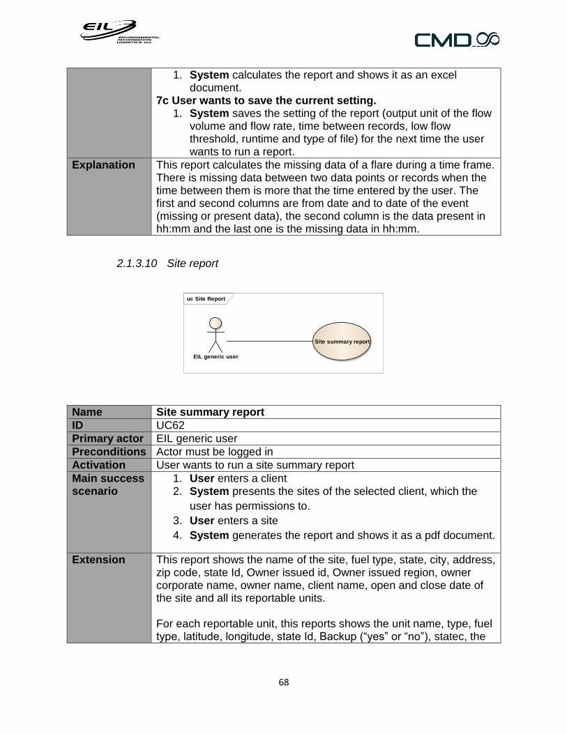
68
1. System calculates the report and shows it as an excel document.
7c User wants to save the current setting. 1. System saves the setting of the report (output unit of the flow
volume and flow rate, time between records, low flow threshold, runtime and type of file) for the next time the user wants to run a report.
Explanation This report calculates the missing data of a flare during a time frame. There is missing data between two data points or records when the time between them is more that the time entered by the user. The first and second columns are from date and to date of the event (missing or present data), the second column is the data present in hh:mm and the last one is the missing data in hh:mm.
2.1.3.10 Site report
Name Site summary report
ID UC62
Primary actor EIL generic user
Preconditions Actor must be logged in
Activation User wants to run a site summary report
Main success scenario
1. User enters a client 2. System presents the sites of the selected client, which the
user has permissions to.
3. User enters a site
4. System generates the report and shows it as a pdf document.
Extension This report shows the name of the site, fuel type, state, city, address, zip code, state Id, Owner issued id, Owner issued region, owner corporate name, owner name, client name, open and close date of the site and all its reportable units. For each reportable unit, this reports shows the unit name, type, fuel type, latitude, longitude, state Id, Backup (“yes” or “no”), statec, the
uc Site Report
Site summary report
EIL generic user

69
start and stops date of the service and calculates the number of records.
2.1.3.11 Time shifted report
Name Time shifted 2-5 minutes report
ID UC60- UC601
Primary actor EIL generic user
Preconditions Actor must be logged in
Activation User wants to run a Time shifted 2 minutes report
Main success scenario
1. User enters a client 2. System presents the sites of the selected client, which the
user has permissions to.
3. User enters a site and the time frame of the report.
4. System presents the reportable units of the site, which the
user has permissions to and have data for the time frame.
5. User enters a reportable unit.
6. System presents the pressure and temperature (barotroll and
ruggetroll) data types the reportable unit keeps tracks of.
7. User enters a data type.
8. System calculates the report and shows it as an excel
document.
Extension This reports uses linear interpolation to interpolate temperature and pressure data every 2 or 5 minutes, in order to compare those parameters of different wells at the same time.
uc Special reports
Time Shifted 5
minutes report
Time Shifted 2
minutes report
EIL generic
user

70
2.2 Data conceptual scheme
An UML conceptual model is a diagram, which relates objects in the system domain
to each other, defining concepts and terms.

71
Textual integrity constraints
- If the Site open and close dates are known the open date is <= than
the close date.
- In a Reportable Unit, the start service date is <= that the stop service
date.
- In a Data Logger, the start service date is <= that the stop service
date.
- There can’t be a file with state “Rejected” or “Registered” and with
records.
External keys:
- Year (year), for the rest of the classes (ID).
Definitions:
Illegal expression: string that contains a file on some rows and it is illegal because it’s
not data.
Item: column of the file to be uploaded, describes the physically measurement value and
the unit.
Record: it’s a line in the file.
Automatic DST dates: they have to be the Daylight saving time dates of every year in
the U.S territory.

72
2.3 Non-functional requirements
2.3.1 Look and feel requirements
ID RNF01
Stakeholder Client, EIL employee.
Description The application must be attractive to EIL employees and their clients.
Rationale Could be a marketing strategy for potential clients. EIL employees will accept the application if it is attractive.
Fit criterion
User satisfaction 3
User dissatisfaction 4
ID RNF02
Stakeholder Client, EIL employee.
Description The application must have the new EIL web site colors.
Rationale It is important that the web site, the application and the company image have homogeneity.
Fit criterion
User satisfaction 4
User dissatisfaction 4
2.3.2 Usability and humanity requirements
ID RNF03
Stakeholder Client, EIL employee.
Description The application must be easy to understand and learn
Rationale The application may not have complicated or not intuitive screens
Fit criterion
User satisfaction 4
User dissatisfaction 4
2.3.3 Performance requirements
ID RNF04
Stakeholder EIL employee.

73
Description The application must upload a file in less than 4 minutes and the user may receive the confirmation email in less than 5 minutes
Rationale It is important that the user could upload multiple files in a short time frame.
Fit criterion
User satisfaction 4
User dissatisfaction 5
ID RNF05
Stakeholder EIL employee.
Description The user must not wait for the application to upload a file and must be able to continue doing another things
Rationale The user should be able to continue working even if the application is processing a file. It will make the user productive.
Fit criterion
User satisfaction 5
User dissatisfaction 1
ID RNF06
Stakeholder Client, EIL employee.
Description The application must generate a report in less than 2 minutes.
Rationale It is important to run quick reports
Fit criterion
User satisfaction 4
User dissatisfaction 3
ID RNF07
Stakeholder Client, EIL employee.
Description Reports must be accurate in their results
Rationale These reports are going to be shown to the client and the EPA.
Fit criterion
User satisfaction 5
User dissatisfaction 4
ID RNF08
Stakeholder Client, EIL employee

74
Description The product must achieve 95 percent uptime.
Rationale
Fit criterion
User satisfaction 3
User dissatisfaction 5
ID RNF09
Stakeholder EIL employee.
Description The application must be flexible and easy to add new requirements.
Rationale Application targets may agree to change the company needs. EPA requirements constantly change.
Fit criterion
User satisfaction 5
User dissatisfaction 1
2.3.4 Maintainability and support requirements
ID RNF10
Stakeholder Client, EIL employee
Description The application must run on explorer and Mozilla Firefox.
Rationale
Fit criterion
User satisfaction 4
User dissatisfaction 4
ID RNF11
Stakeholder Client, EIL employee
Description The application must run under windows server 2008 R2 in a cloud server.
Rationale The server will be in the cloud.
Fit criterion 5
User satisfaction 1
User dissatisfaction
2.3.5 Security requirements
ID RNF12
Stakeholder EIL employee

75
Description Only EIL employees with administrator privileges can delete data
Rationale The data deletion needs to be controlled.
Fit criterion
User satisfaction 5
User dissatisfaction 3
ID RNF13
Stakeholder EIL employee
Description Only EIL employees with administrator privileges can add sites, clients, illegal expressions, and users and run the statistics report.
Rationale These functionalities may be controlled.
Fit criterion
User satisfaction 5
User dissatisfaction 3
ID RNF14
Stakeholder Client
Description Client must be allowed to run only reports
Rationale
Fit criterion
User satisfaction 5
User dissatisfaction 3
ID RNF15
Stakeholder EIL employee
Description The application must prevent duplicated data from being introduced.
Rationale Duplicated data is a common mistake that should be prevented.
Fit criterion
User satisfaction 4
User dissatisfaction 2

76
3 System Architecture
3.1 Description
This section presents the architecture as a series of views and diagrams: use case
view, package view, classes diagram, data base diagram and deployment view. These
views are presented as models that have been constructed using UML.
According to the functional requirements, the architecture of the system has been
oriented to provide the adequate infrastructure to support the massive data
processing. Using files as the input of the system and data reporting as the output,
reporting tools are used to generate excel and pdf documents.
3.2 Used Technologies
The company requires the worker to use the majority of the tools listed below:
- Application Server IIS: (Required by the company)
Application Server provides an integrated environment for deploying and
running custom business applications that are built with Microsoft
.NET Framework. When you install the Application Server role, you can choose
services that support applications that are built to use COM+, Message
Queuing, Web services, and Distributed Transactions. [4]
- WCF (Windows communication foundation): is a framework for building
service-oriented applications. Using WCF, you can send data as asynchronous
messages from one service endpoint to another. A service endpoint can be part

77
of a continuously available service hosted by IIS, or it can be a service hosted
in an application. An endpoint can be a client of a service that requests data
from a service endpoint. The messages can be as simple as a single character
or word sent as XML, or as complex as a stream of binary data. [5]
- .NET framework : (Required by the company)
Software framework developed by Microsoft that runs primarily on Microsoft
Windows. [6]
- Asp.net: ASP.NET is a free web framework for building Web sites and Web
applications using HTML, CSS and JavaScript. [7]
- ADO.net: is a set of classes that expose data access services for .NET
Framework programmers. ADO.NET provides a rich set of components for
creating distributed, data-sharing applications. It is an integral part of the .NET
Framework, providing access to relational, XML, and application data.
ADO.NET supports a variety of development needs, including the creation of
front-end database clients and middle-tier business objects used by
applications, tools, languages, or Internet browsers. [8]
- MSMQ (Message Queuing): is a technology, which allows applications running
at different times to communicate across heterogeneous networks and systems
that may be temporarily offline. Applications send messages to queues and
read messages from queues.
- SQL server 2008 R2 (Required by the company):
Relational database management system developed by Microsoft.

78
- Reporting services 2008: is a tool used to create, deploy and manage reports
and includes programming features that helps to customize a reporting
functionality in a system.
Software and hardware
- Data Base: Microsoft SQL server 2008 R2 Web edition is used as the
data base software.
- Programming platform: .net framework 4.0 is used as the platform and
c# is used as the programming language.
- Reporting tool: it is used reporting services 2008 R2.
- Application server: IIS 7.5 is used as the web server.
- Windows server: is Windows server 2008 R2 and is provided by
Rackspace. This server is in the cloud.
- Cloud provider: Rackspace.

79
3.3 Use case view
This view represents the most significant stages of the functionality that should cover
the solution and also those that have architectural scope.
uc Use Case Model
Facility set up
+ EIL Admin
+ EIL generic user
+ Data Format Items (add,modify,delete)
+ Client (add, modify, delete)
+ Data Format (add,modify,delete)
+ Data Logger(add,delete, modify)
+ Delete ftp server configuration
+ folder path configuration(add,edit,delete)
+ Ftp server configuration (add,modify,delete)
+ Manage Clients
+ Manage data format Items
+ Manage Data formats
+ Manage Dataloggers
+ Manage ftp servers
+ Manage reportable units
+ Manage sites
+ Manual daylight saving time dates (add,modify,delete)
+ Manual DST dates (add, modify, delete)
+ Modify ftp server configuration
+ Reportable Unit (add,delete, modify)
+ Site (add,delete,modify)
Data Entry
+ Clock
+ EIL generic user
+ EIL user
+ Download FTP files
+ List ftp servers
+ Manage FTP download schedule
+ Manual Entry (add, delete, modify)
+ Manual ftp download
+ Modify ftp server configuration
+ Scheduling ftp download (add,edit,delete)
+ Upload data from a single fi le
+ Upload fi le
Data Deletion
+ EIL Admin
+ Data deleletion by fi le
+ Data deletion by time frame
+ Delete Duplicated Data
+ Large Block Data Deletion
+ Use Case1
Reporting
+ Flow Reports
+ Missing data reports
+ Operating Reports
+ Query reports
+ Site Report
+ Special reports
+ Temperature reports
+ Average Max Min Flow reports (Daily, weekly, monthly, yearly)
+ Avg, Max, Min Temp reports (Daily, weekly, monthly, yearly)
+ Daily Back Weighted Flow Report
+ Data chart
+ Data report
+ Flow Reports (Daily,weekly,monthly,yearly)
+ Missing data Reports (Daily,weekly,monthly,yearly)
+ Monthly temperature report
+ Multiple reportable Units data report (1-10 reportable units)
+ Site Summary Report
+ Temperature report
+ Time Shifted 2 minutes report
+ Time Shifted 5 minutes report
+ Uptime Downtime Reports (Daily,weekly,monthly,yearly)
Administration
+ Client
+ EIL Admin
+ Eil generic user
+ Add permissions
+ Change password
+ Data Base Statistics Report
+ Ilegal Expressions (add)
+ Ilegal Expressions (delete)
+ Ilegal Expressions (modify)
+ Ilegal Expressions site (add, delete)
+ Manage permissions
+ Manage users
+ See log fi le
+ User (add, modify,delete)
+ User permissions (add, delete)
Documents
+ EIL Admin
+ EIL user
+ Documents (add, modify,delete, view)

80
- Facility set up
Functionality in which all the variables involved in the process of importing a file
are configured.
- Data Entry
Feature that allows data input into the system either through files or manually.
- Data Deletion
Functionality that allows deletion of data from the system.
- Reporting
Functionality that allows analysis of data using specific algorithms and generate
user-friendly reports.
- Administration
Functionality that allows the user to configured other users and manage the
system.
- Documents
Feature in which EIL documents for the EPA are saved in order to facilitate
tracking.
3.4 Package view
This diagram shows the architecture of the application seen as layers where each
layer provides specific functionality for a section of the system. The layers are
organized to provide support and basic functionality to other layers and will help
the user to understand how the information is organized.

81
Presentation tier: This tier uses a MVC (Model View Controller) framework provided by
ASP.NET (winforms). The aspx file (View) is the file that contains all the code that the
user sees on the browser. In addition, it receives user requests. The aspx.cs file
(Controller) processes the actions of the aspx file and connects the presentation tier with
the business tier (facades).
pkg PackageDiagram
Presentation
Site Client
DataFormatDataFromFile
AutomaticData
Business
Web Serv ices QueueFacades
BLL
Reports
Data
DAOS ADO.net
ReportableUnit
DataLogger
Reporting
DataDeletion
DataManually
DocumentsIllegalExpressions User
«use»
«use»

82
Business Tier: In this layer there are all the BLL (Business logic layer) classes. There
is a BLL for each table in the data base. Each BLL will have methods for inserting,
updating, deleting etc. from the respective table, and for applying the business rules.
Besides, there is a web service and a queue class, which help the upload file process to
be done.
Data Tier: The Ado.net can be found in the Data Tier in an xsd type file called DataSet.
In this file Table Adapters are created, which are objects that interact with the tables in
the data base. Each table possesses a Table Adapter which contains the queries to
access the table. Besides table adapters this tier has the DAOs (Data Access object),
that interact with the tables in ways the table adapters.
3.5 Deployment view
A diagram representing the implementation of logic and physical level conceptual
architecture is presented that includes all physical and software and hardware
components involved in the solution.

83
To understand the technologies that were used, please go to section 3.2
deployment Deployment Diagram
«device»
Rackspace cloud Server
Daba Base SQL
server 2008R2Reporting services
2008R2
Aplication Server IIS
.Net framework
ADO.net
«device»
Client workstation
Browser
WCF
ASP .net
MSMQ (Microsoft
Message Queuing)
«use»
«use»
«use»
«use»
«use»
«use»
«use»
https
«use»

84
3.6 Analysis and Design
3.6.1 Class diagram
In UML, class diagrams are one of six types of structural diagram. Class diagrams
are fundamental to the object modeling process and model the static structure of a
system. You can use several class diagrams to model the components of a system.
[9]
This diagram is the result of refining the data conceptual scheme.

85
Note:Due to the number of records contained in the t_Record table and queries to be made, it was decided that the table has a foreign key to
t_MeasurementType, t_MeasurementUnit and t_DataLogger.

86
3.6.2 Data base diagram
This diagram is the result of refining the data conceptual scheme and it has been adapted to a
relational data base.

87
3.6.2.1 Physical design of the data base
Table Partitions: The largest table in the data base is the t_Record table. Every time a
user uploads a file it grows larger, and in time, it becomes more difficult to manage and
query it. That is why it was decided to partition it.
The Horizontal partition method was used, because the amount of rows grows continuously
and it grows depending on one column (the reportable unit id column). The table is divided
into 3 tables and each one of them contains the data of different reportable units.
Indexes:
The three t_Record tables have the following indexes:
1. IX_t_Main_DataLogger: datalloger Id
2. IX_t_Main_Deletion: Date, reportable unit and data type field.
3. IX_t_Main_FileId: File Id field
4. IX_t_Main_Group: Reportable unit and Date, including the data value, data units,
data type and time zone of the date.
5. IX_t_Main_RecordNum: over the primary key record number.
6. IX_t_MainDate: date field.
3.6.3 Analysis after reverse engineering
After analyzing and designing the use cases of the old code some bad designs were found.

88
Issue/Use Case
Layer Note Decision
UC 70, UC71 User permissions
Data Base Bad design in the table t_Permission NO
UC48-UC59 Reports
Data Base Bad design in the table where the settings of the report are storage. t_OperatingReportsConfig, t_DataReportsConfig,
NO
UC09-UC12 Reportable Unit
Data Base Bad design in the table t_MasterSiteRepUnit_TMainTableName
NO
Table Name Data base The name of the business concepts have change with the time and the name of the tables don’t explain what they are any more.
Yes
Table Partition
Data Base/Business layer
T_Record table has to be divided into 3 tables due to the amount of data. The code has a lot of queries with the name of the table. The business layer has to find which table to use to insert, update, select or delete data. There was found one partition that was done incorrectly, then the code has to be corrected with a new flexible an understanding code.
Yes
A lot of business logic on the view
Presentation
Most of the functionality has too much logic in the view classes. They can be moved to the business layer.
Yes, but just in critical use cases
Some old code is not being use and it is not working.
All layers Some functionality is not being used, so a decision has to be made whether to delete it or fix it.
NO
Some patterns can be added to improve the functionality.
Business layer
Cache pattern, Service Locator. Yes, just the service locator pattern
Façade patter is not been implemented very well
Business layer
There are too many facades. It can be grouped by functionality.
Yes

89
UC 12 Delete Reportable Unit, UC08 Delete Site
Business layer
Deleting a reportable unit and a site requires many items to be deleted as they have foreign keys. All the things were not deleted and it wasn’t clear who has to delete them.
Yes
EIL didn’t approve the improvement of all the reverse engineering use cases. Instead, it
came to the conclusion to improve the most important and critical use cases:
o Uploading File process: This process is one of the most important processes in the
application, since it is in charge of populating the data base with the data that comes
in files and will be reported it later. There was found too much business logic in the
view, poor flexibility and lack of Low Coupling pattern in the code. Also a message
queue, web service and an email response after the process is done has to be added
in order to accept uploading files requests from different sources, such as the new
and use cases.
o Before applying the reverse engineering the application used the Façade pattern but
it wasn’t being used in the correct way. It didn’t offer a simple interface which connects
the view to the business layer (several facades) and didn’t group the process of the
application by functionality making it less flexible to new features and less
understandable. This change will affect most of the use cases.
o The most important table in the data base is the t_Record table. It has to be partitioned
into 3 table and be flexible to accept more partitions in the future. The use cases that
use this table need to know which table to use to select, insert, update or delete data.

90
3.6.4 Proof of concept
A proof of concept for the use case UC41 Manual FTP download was built to decide what
technology to use for the new requirements. This proof was implemented using SQL
Server Integration Services (SSIS).
Three modules were implemented. One for setting up the paths where the files were going to be
downloaded. Another to connect to the ftp server and download the files and the last one to
connect to the web application though a web service and import the files to the CMD data base.

91
3.6.5 Evaluation of the proof of concept
After implementing the proof of concept, a decision had to be made. One option was using IIS
or another solution just using C# and windows tools. A parallel was done to see the pro and
cons of both solutions.
SSIS C# programming
One technology and one file will be in charge of executing the new requirements.
A simple solution will have a lot of tools involved, configuration files and more things that can fail.
Handling of exceptions are unclear in this tool.
Simple programming in C# can handle a lot of exceptions
New way to programming has to be learned.
Programmer doesn’t have to learn c#.
Monthly cost for the new license Free
The solution is simplest to understand. The tool makes it understandable.
A solution using c# is not simple to understand, because it doesn’t have a visual tool.
The SSIS package has to be executed in the IIS (Application service). It will make the server busier and the response time can be affected.
A solution in c# can be implemented out of the IIS.
After analyzing this chart EIL decided to not use this technology mainly because it would be
expensive to update the data base to a version where this tool can be used and it was not cost
effective to buy a powerful tool with a lot of features to use just one of them.
3.6.6 Sequence Diagram
All the sequence diagrams of the use cases were made using the Enterprise Architect tool.
In this document are presented the following use cases:
o Old use cases: two diagrams.
o New use cases: all of them.

92
o Use cases to be corrected: EIL approved to correct just one.
3.6.6.1 Reverse engineering old use cases.
3.6.6.1.1 UC08 Delete site.
sd UC08-DeleteSite
EILAdminatrator
FacilitySetUpFacade
AddSiteScreen
:SiteBLL :SiteTableAdapter:ReportableUniBLL PermissionsBLL :DocumentsBLL DataLoggerBLL :FtpServerBLL
loop
[for each repunit in the site]
deleteSite(idSite)
deleteSite(siteId)
deleteRepUnitsBySite(siteid)
deleteReportableUnit(repUnit_Id)
deletePermissionsBySite(siteId)
deleteDocumentsBySite(siteId)
deleteDataLoggers(siteId)
deleteServersBySite(siteId)
deleteSite(siteId)

93
3.6.6.1.2 UC12 Delete Reportable Unit
sd UC12-DeleteReportableUnit
EIL generic user
:FacilitySetUpFacade
Add Reportable
Unit screen
:Reportable
UnitBLL
:ReportableUnitTableAdapterRecordBLL DataFormatBLL PermissionsBLL DocumentsBLL DataLoggerBLL :FtpDownloadScheduleBLL
deleteReportableUnit(rep_unitId)
deleteReportableUnit(repUnitid)
deleteRecordsByRep_Unit(rep_unitId)
deleteDataFormatsByRep_Unit(rec_unitId)
deletePermissionsByRec_Unit(rec_unitId)
deleteCalibrationData(repUnitId)
deleteDataloggerByRepUnitRelation(rep_unitId)
deleteFtpSchedulesByRepUnit(rep_Unit)
delete(rep_unitId)

94
3.6.6.2 Reverse engineering use cases to be improved
3.6.6.2.1 UC42 Upload data from a single file
The use of new facades, which group functionality are used in this use case as
others, too.
sd UC42-UploadDatafromSingleFile
EIL generic userUpload file
screen
:FacilitySetUpFacade :ClientBLL :SiteBLL :ReportableUnitBLL :DataLoggerBLLDataFormatBLL
UploadFileQueue
registerFile :ServiceLocator QueueService
getAllClients()
getAllClients()
getpermitedSites(clientId, userId)
getPermitedSites(clientId, userId)
getPermitedRepUnits(siteid, userid)
getPermitedRepUnits(siteid, userId)
getDataFormats(rec_unitId)
getDataFormats(rec_unitId)
getDataLoggers(rec_unitId)
getDataLoggers(rep_unitId)
uploadFile(rep_unitId, userid, note, fi leName, dataLogId, dataFormatId)
RegisterFile()
findQueueServ ice()
queueMessage(message)
queueMessage(message)

95
3.6.6.3 New use cases to be implemented
3.6.6.3.1 UC43 Upload file
Before, uploading a file was simple. The user selected the information
including the file and then there was a method which was in charge of
reading the file and generating a report with the errors, rejected data or
a success message. The user waited, watching the screen for the report.
Prior to the new requirements, this use case was used only by use case
UC42. Afterwards it had to change in order to comply with the new
requirements.
uc Data Entry
Upload data from a
single file
EIL generic user
Manual ftp download
Clock
Download FTP files
Upload file
«extend»
«extend»
«extend»

96
Windows Service:
It was decided to create a windows service and a message queue to receive the
message for the different sources or ways to upload a file.
Web Service
It was decided to create a web service which is called by the windows service to upload
a file into the data base. After validating and reading the file, the system sends an email
to the user with the report of the process.
sd UC43-UploadFileWindowsServ ice
Upload File
Queue
:FlareDB_QueueService
UploadFileWebService
message= unqueue() :String
messageProcessing()
uploadFile(fi leId, dataFId, dataLogId, hourF, hourB, userId)

97
sd UC43-UploadFileWebServ ice
UploadFileWebServiceUploadFileQueue
:FileBLL:DataEntryFacade :DataRecordDAO :EmailFileDAODataRecordBLL RepUnitxTRecordTableAdapter
loop
[for each line in the file]
alt
[If validate==True]
[validate==False]
loop
[for each line in the file]
alt
[duplicatedDataFile==False]
[dupliactedDataFile==true]
alt
[DupDataBase==false]
[DupDataBase==true]
uploadFile()
validateFile()
validate= validateFile() :
Boolean
validate= validateLine() :Boolean
readFile()
createTemporaryTable()
insertTemporaryTable()
duplicatedDataFile= thereIsDuplicatedDataIntheFile() :
Booelan
DupDataBase= thereIsDuplicatedDataIntheDataBase()
insertTRecord_FromTemporaryTable(rec_unit, UserID)
tableName= getTableByRec_Unit(rep_unit) :String
insertTRecord_FromTemporaryTable(tableName, userId)
updateStateFile("Loaded")
sendEmail(user, sucess)
updateStateFile("Rejected")
updateStateFile("Rejected")
deleteTemporaryTable()
sendEmail(user, failure)

98
3.6.6.3.2 UC40 Download FTP Files
New requirements were recently added to this project. The Files to be uploaded are in a
remote ftp server that belongs to EIL’s clients. These files are generated every day with
the data of the day. In order to reduce the amount of time that a user needs to upload a
file every day, EIL wanted to automate this process.
When a ftp download schedule is created a sql server job is created, too. The job will be
executed depending on the time it was planned. It sends a message to the download ftp
queue.
Windows Service:
Once the message arrives to the queue. It is processed, a windows service is in charge
of download the files of the given time frame, registers them to the data base, saves them
into the hard disk of the server and sends a message to the upload file queue to be
uploaded.
sd UC40-DownloadFTPFiles
Clock
SQLServerAgent StoreProcedureSendMSMQMessage
DownloadFTPFilesQueue
Sql job
execute()
execute()
uspMSMQSend(message)

99
3.6.6.3.3 UC29-UC32 FTP Server Configuration
In order to create a download schedule it is necessary to add and store the ftp servers
and its paths.
sd UC40-DownloadFTPFilesWindowsServ ice
DownloadFTPFilesQueue
:Console
Aplication
UploadFileQueue
:EmailService FtpService QueueService
Ftp Sever WebService
loop
[for each file in the ftp server and time frame]
alt
[Not Exception]
[Exception]
loop
[for each file downloaded]
unqueue(message)
downloadFiles()
readFiles()
OpenRead(path)
sendSuccesfulMail()
registerFile()
renameFile()
queue(message)
queue(message)
sendEmail(user, admin, failure)

100
sd UC29-ListFTPServ erConfiguration
Generic EIL user
List Ftp serv er
configuration
:FacilitySetUpFacade FtpServerBLL FtpServerTableAdapter
getAllClients()
getSitesbyUser(clientId, userId)
getFtpServerBySite(siteId)
getFtpServerBySite(siteId)
getFtpServerBySite(siteId)
sd UC30-AddFTPServ erConfig
Generic EIL user
Add Ftp serv er
configuration
:FacilitySetUpFacade FtpServerBLL FtpServerTableAdapter
Ftp Serv er
alt
[connection== true]
[connection== false]
Connection Failed.
Please be sure that the
server exits
addServerConfig(...)
addServerConfig(...)
connection= Connect(serverName, Password) :Boolean
insert(...)

101
sd UC31-ModifyFTPServ erConfig
Generic EIL user
Modify Ftp serv er
configuration
:FacilitySetUpFacade FtpServerBLL FtpServerTableAdapter
Ftp Serv er
alt
[connection == true]
[connection == false]
Connection Failed.
Please be sure that the
server exits
modifyServerConfig(serverId, ...)
modifyServerConfig(serverId,
...)
connection= Connect(serverName, Password) :Boolean
update(serverId, ...)

102
3.6.6.3.4 UC33-UC35 FTP Server Path
sd UC33-AddPathFTPServ er
Generic EIL userAdd a folder
path Screen
FacilitySetUpScreen FTPServerBLL FTPFolderpathTableAdapter
FtpServer
alt
[exists=true]
[existsServer=true && !exists]
[false]
The path: -----
already exists
The path doesn't
exists in the
server
exists= exitsPath(path) :Boolean
exists= exitsPath(path) :Boolean
exitsts(path)
existsSever= existsPathInServer(serverId, path) :Boolean
existsPathInServer(serverid, path)
connects(serverName, password, path)
addPath(path,
serverId)
addPath(path, serverId)
insert(path, serverId)

103
3.6.6.3.5 UC41 Manual FTP download
This functionality will allow the user to manually download files from a ftp server without
creating a schedule.
sd UC34-ModifyPathFTPServ er
Generic EIL userAdd a folder
path Screen
FacilitySetUpScreen FTPServerBLL FTPFolderpathTableAdapter
FTPServer
exists= exitsPathinServer(path) :Boolean
exists= exitsPathinServer(path) :Boolean
getServer(idServer)
connect(serverName, password, path)
ModifyPath(path,
serverId)
addPath(path, serverId)
insert(path, serverId)
sd UC35-DeletePathFTPServ er
Generic EIL userDelete a folder
path Screen
FacilitySetUpScreen FTPServerBLL FTPFolderpathTableAdapter
delete(pathId)
delete(pathId)
delete(pathId)

104
sd UC41-ManualFTPdownload
EIL generic userManual FTP
download
:FacilitySetUpFacade :DataEntryFacade
Ftp Download
Queue
getAllClients()
getpermitedSites(clientId, userId)
getPermitedRepUnits(siteid, userid)
getDataFormats(rec_unitId)
getDataLoggers(rec_unitId)
getFtpServersBySite(siteId)
getPathsByServer(serverId)
download(....)
queue(message)

105
3.6.6.3.6 UC52 Back Weighted Flow Reports
sd UC50-FlowRepot
Daily,weekly,
monthly or yearly
flow report screen
ReportingFacade FlowReport UnitConversionFacade
Reporting
Serv ices
Generic user
alt
[exists==true]
[exists==false]
There is duplicated data,
please delete it, on order
to continue
alt max and min v alues is activ ated
[true]
[false]
alt
[data is in CFM m3/min]
existsDuplicatedData(...)
askForPreasureParameter(...) :Boolean
popUpShow()
generateUnitsConversionTemporaryTable2FlowParameters(...)
generateDailyAveraReport(...)
generateGeneralUnitsConvertion1Parameter(...)
generateDailyFlowRepor(...)
flowReportTableConvertion(...)
showReport(option)

106
3.6.6.3.7 UC58 Temperature Report
sd UC58-TemperatureReports
Generic user
Temperature report
screen
Facility Set up
Facade
Reporting
Facacade
UnitConversionFacade
ReportingServ ices
alt
[exists==true]
[flase]
alt
[Max and min are activated]
[false]
getTemperatureTypesByRep_Unit(rec_unit)
exists= existsDuplicatedData() :Boolean
generateTemperatureUnitsConversion(temp1, temp2)
generateMonthlyAverageTemperatureReport()
generateTemperatureUnitsConversion(temp1)
generateMonthlyTemperatureReport()
show()

107
4 Testing
Before this project began, the integration tests were the only tests that were performed.
The developer would test the new requirement of the application from the web tier in his
own test environment. After these tests were approved, the programmer was responsible
for deploying the new version in the client test environment and a user was in charge of
testing the new functionality. Finally, after passing the tests the new version is deployed
in the production environment.
At this stage of the project, EIL saw the need to add unit tests, that’s why it was approved
to program unit tests for the old code and new one. However, due to the limited time of
the project it has not been able to finish them all (One quarter of the testing has been
done). This is expected to be done after the thesis is completed.
Stress testing is one of the most interesting things EIL wants to develop in this project.
They want to know how many records the principal tables of the data base can handle
without putting at risk the response time of the reports. This is also something that will be
developed after the thesis.

108
5 Project planning and costs
It is estimated that the project will last 8 months. The worker has to develop the thesis
and at the same time has to be giving support to the application and correcting bugs of
the old code.
5.1 Planning
Task Hours
Documentation-use cases 180
Design 50
Proof of concept 50
Implementation new Interface 50
Implementation reports 150
Implementing new code 100
Deploying -test-defects 50
Unit test 60
Stress testing 40
Meetings 30
Writing Thesis 70
Deploying production 20
Defects 30
TOTAL 880
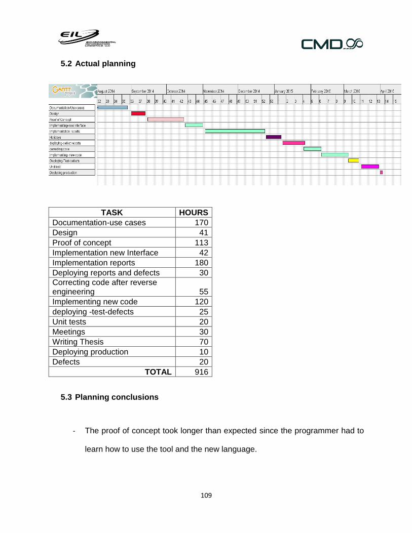
109
5.2 Actual planning
TASK HOURS
Documentation-use cases 170
Design 41
Proof of concept 113
Implementation new Interface 42
Implementation reports 180
Deploying reports and defects 30
Correcting code after reverse engineering 55
Implementing new code 120
deploying -test-defects 25
Unit tests 20
Meetings 30
Writing Thesis 70
Deploying production 10
Defects 20
TOTAL 916
5.3 Planning conclusions
- The proof of concept took longer than expected since the programmer had to
learn how to use the tool and the new language.

110
- The new reports took 30 hours more than the original plan, because of its
complexity.
- A new task had to be added, correcting code after reverse engineering. Due to
the documentation and design a few mistakes were found in the code. Most of
them were bad design problems.
- Deploying took longer because it had to be done twice. EIL needed the reports
working by January of 2015 and the new functionality was not ready.
- The stress testing could not be done because there was not enough time to do
it.
- The unit test task was not completed because there was not enough time to do
it.
5.4 Costs
These are the costs of the project.
Item Price Note Explanation
Computer $2,500 Dell computer and software
1 Worker $18,320 900 hours ,$20 dollars/hour
The hourly price is the same for tasks such as analysis and development.
Skype subscription (US calls)
$60 a year
The company is located in the U.S, the worker has to call frequently to different users.
SQL server 2008 R2 developer license
$60
Internet access 1 person
$400 8 months , $50 dollars a month
The company agreed to pay the internet access

111
because the worker works at home.
TOTAL $21,280
Notes:
The server was already rented, so it doesn’t appear on the costs table.
The programmer doesn’t have the access to the information of the bill.
There is not an office because the programmer works at home.

112
6 Future Work
This project doesn’t end with this thesis. The programmer (Paola Vera) will continue
working for EIL. Since more work has to be done. This is a list of the things EIL wants to
work on.
Stress testing over the T_Records tables, which are the most important tables.
Unit tests testing. Create unit test for every functionality on the application.
EIL wants to be able to automatize the manual uploading file process. The
download ftp file module and how it works can fit this requirement because instead
of having people uploading files, they can be saved in a ftp server and be
downloaded automatically. This module has to be improved and extended.
Correcting all the defects that were found in the reverse engineering process.
Create a user manual for the new features.
Create a document with all the software documentation.

113
7 Conclusions
Many companies do not understand the importance of each stage in the software
development cycle, which is why many of these are sacrificed to reduce costs and delivery
times. EIL did not see the need to comply with the requirements analysis, application
design and unit testing, so many mistakes were made.
The reverse engineering process allowed them to realize those mistakes, but the
correction of them is much more difficult when the application is in production. It would
have been easier and cheaper to fix if they had been found in earlier phases of software
development, but these early stages were not made. Furthermore, the time for the
correction of these defects was not fully contemplated therefore other tasks had to be
postponed.
On other hand, the reverse engineering of all use cases which are the specification,
analysis and design, could be made. Also, the main defects could be corrected, allowing
the application to be more flexible and adaptable to new requirements that may arise in
the future.
In addition, the new requirements were all documented and implemented and they are in
production already. EIL is very satisfied with this new feature (download files from a ftp
server and upload them into the data base). It saves time, effort and money.

114
Personally, it was very rewarding to help automate some processes of the company and
make life easier for its employees. On the other hand, I was able to learn new
technologies and ways to solve complex programming problems.

115
8 References
[1] ] "EIL," [Online]. Available: http://www.eilllc.com/. [Accessed May 2015].
[2] IBM, "Rational Unified Process," [Online]. Available: https://www.ibm.com/developerworks/rational/library/content/03July/1000/1251/1251_bestpractices_TP026B.pdf.
[Accessed May 2015].
[3] "Enterprise Architect," [Online]. Available: http://www.sparxsystems.com/products/ea/.
[Accessed May 2015].
[4] "Application Server IIS," [Online]. Available.
http://technet.microsoft.com/enus/library/cc725986.aspx. [Accessed May 2015].
[5] "WCF," [Online]. Available: http://msdn.microsoft.com/en-us/library/ms731082(v=vs.110).aspx.
[Accessed May 2015].
[6] ".Net," [Online]. Available: http://en.wikipedia.org/wiki/.NET_Framework. [Accessed May 2015].
[7] "Asp.net," [Online]. Available: http://www.asp.net/. [Accessed May 2015].
[8] "Ado.net," [Online]. Available: http://msdn.microsoft.com/en-us/library/e80y5yhx(v=vs.110).aspx.
[Accessed May 2015].
[9] "UML," [Online]. Available: http://pic.dhe.ibm.com/infocenter/rsarthlp/v9/index.jsp?topic=%2Fcom.ibm.xtools.modeler.doc%2Ftopics%2Fcclassd.html. [Accessed May 2015].

116
9 APPENDIX
1. Back Weighted Flow Reports
1.1 Parameters
Field Name Required
Type Restrictions Units Description
Missing data time criteria
x Numeric
Must be greater than 0.
Minutes, hours or days based on user selection.
It is maximum time between data points
Flow data types
x Text Flow data types. Records may or may not be present in the selected time period.
None
Flow data types of the selected reportable unit.
Flow Volume Output Units
x Text M3 stp MMSCF MSCF SCF
The calculated flow volume will be shown in the user selected unit.
Use the Min and Max Values
x Text The user may check it when the selected flow data type is min or max. If it is unchecked won’t be averaging.
None
When the user checks it the flow values will be equal to the average of the min and max values.
Low Flow Threshold Value
x Numeric
Must be a numeric value
SCFM It’s the minimum flow rate for which the flare is operational
Flow Rate Output Units
x Text M3 stp/day M3 stp/ hour M3 stp/minute SCFM
The calculated flow rate will be shown in the user selected unit.
Runtime x Text Minutes, Elapsed time of present data will

117
Hours or days based on user selection.
be shown in the user selected unit.
Generate Reports as
x Text Excel file looks like the pdf report, but has unusual formatting. Excel Data just shows the data without odd formatting.
-PDF -Excel -Excel Data -Excel Formulas* (* Back Weighted report)
Provides the user with a choice of export file types.
1.2 Specification
This is the algorithm specification. It tells us how the report works.
For One Value Flow Rate Data
Beginning of Period
End of Period
Time T0 T1 T2 T3 T4 T5 T6 T7 T8 Tn
Data FR0 FR1 FR2 FR3 FR4 FR5 FR6 FR7 FR8 FRn
Calculate T1 T2 T3 T4 T5 T6 T7 T8 Tn
Calculate F1 F2 F3 F4 F5 F6 F7 F8 Fn
Notes:
n >= 1
Threshold = user select value below which the flow rate is not reliable
FRn = FRn if FRn >= Threshold
= 0 if FRn < Threshold
= 0 if FRn does not exist
T default = user select, typical 15 minutes
Non exisitng Data/Time = exist if Tn - Tn-1 <= T default
= not exist if Tn - Tn-1 > T default

118
= variable
if Tn - Tn-1 > T default then Missing Data from Tn-default to Tn-1
Tn = Tn - Tn-1 if Tn and Tn-1 exist
= T (default) if Tn-1 does not exist
= 0 if Tn does not exist
Period beginning = user select
if the beginning of the reporting period does not fall on a recorded data point set T0 to be
equal to the beginning of the reporting period.
Period end = user select if the end of the reporting period does not fall on a recorded data point set Tn to be
equal to the end of the period and extrapolate the flow rate from the closest flow data
Fn = FRn * Tn
Flow Volume = Sum of Fn
Run Time = Sum of Tn
Average Flow Rate =
Flow / Run Time
Period Time = Tend - T0
Average Period Flow Rate = Flow / Period Time