cmf series - nortek global hvacenora.nortekhvac.com/literature/067a.pdf · fan/limit switches ......
TRANSCRIPT

CMF Series
Service Manual
PO and PG Furnaces

2
Index
Page
Introduction .......................................................................................................................... 3
Electrical Supply & Polarity .................................................................................................. 3
Door Switch .......................................................................................................................... 4
Fan/Limit Switches ............................................................................................................... 4
Blower Motor ........................................................................................................................ 4-5
Oil Burner ............................................................................................................................. 5
Oil Pump .............................................................................................................................. 5-6
Natural to LP Conversion ..................................................................................................... 6
Igniter (Power Gas Only) ...................................................................................................... 7
Primary Control .................................................................................................................... 7
Cad Cell ............................................................................................................................... 8
Ignition Transformer ............................................................................................................. 8
Electrode Setting .................................................................................................................. 9
Combustion Air Band ........................................................................................................... 9
Air Housing, Blower Wheel................................................................................................... 10
CB200A Base....................................................................................................................... 10
Troubleshooting Flow Charts ............................................................................................... 11-15
Service Guide ....................................................................................................................... 16-17
Oil to Gas Conversion .......................................................................................................... 18-22
Wiring Diagrams ................................................................................................................... 23-24
This service manual is primarily intended to assist qualified individuals experienced inservicing heating and air conditioning appliances and is not intended to be used byunqualified personnel.
Performing service as outlined in this service manual will require the use of calibrated testinstruments. Using uncalibrated test instruments will result in faulty diagnoses. Allinstruments should be used in accordance with the manufacturer's instructions.
CAUTION:!
3
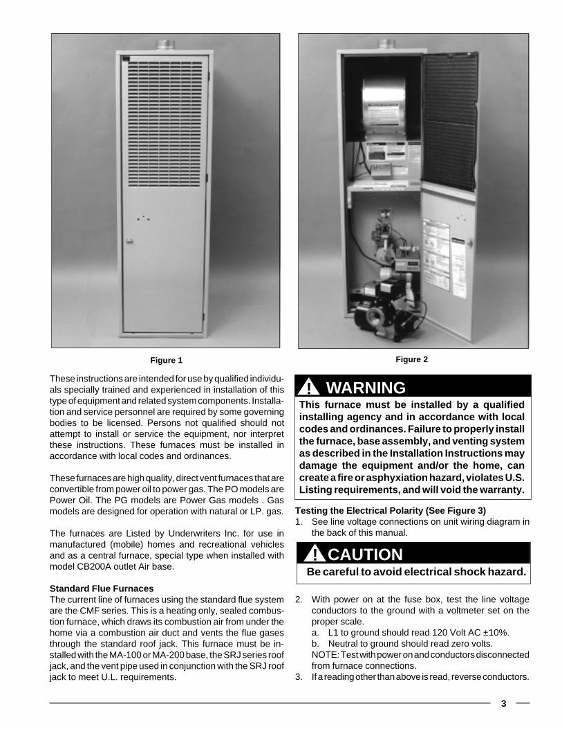
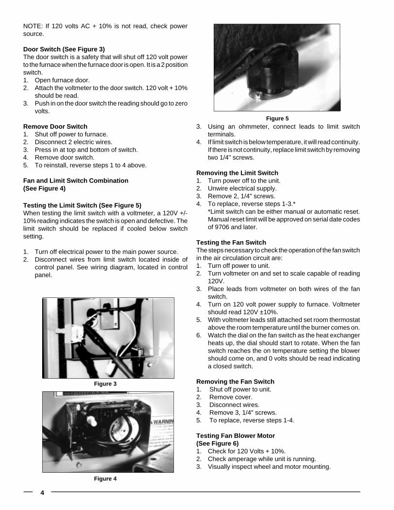
These instructions are intended for use by qualified individu-als specially trained and experienced in installation of thistype of equipment and related system components. Installa-tion and service personnel are required by some governingbodies to be licensed. Persons not qualified should notattempt to install or service the equipment, nor interpretthese instructions. These furnaces must be installed inaccordance with local codes and ordinances.
These furnaces are high quality, direct vent furnaces that areconvertible from power oil to power gas. The PO models arePower Oil. The PG models are Power Gas models . Gasmodels are designed for operation with natural or LP. gas.
The furnaces are Listed by Underwriters Inc. for use inmanufactured (mobile) homes and recreational vehiclesand as a central furnace, special type when installed withmodel CB200A outlet Air base.
Standard Flue FurnacesThe current line of furnaces using the standard flue systemare the CMF series. This is a heating only, sealed combus-tion furnace, which draws its combustion air from under thehome via a combustion air duct and vents the flue gasesthrough the standard roof jack. This furnace must be in-stalled with the MA-100 or MA-200 base, the SRJ series roofjack, and the vent pipe used in conjunction with the SRJ roofjack to meet U.L. requirements.
Figure 1 Figure 2
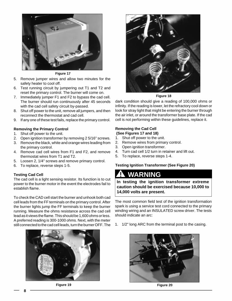
Testing the Electrical Polarity (See Figure 3)1. See line voltage connections on unit wiring diagram in
the back of this manual.
WARNINGThis furnace must be installed by a qualifiedinstalling agency and in accordance with localcodes and ordinances. Failure to properly installthe furnace, base assembly, and venting systemas described in the Installation Instructions maydamage the equipment and/or the home, cancreate a fire or asphyxiation hazard, violates U.S.Listing requirements, and will void the warranty.
!
2. With power on at the fuse box, test the line voltageconductors to the ground with a voltmeter set on theproper scale.a. L1 to ground should read 120 Volt AC ±10%.b. Neutral to ground should read zero volts.NOTE: Test with power on and conductors disconnectedfrom furnace connections.
3. If a reading other than above is read, reverse conductors.
CAUTION Be careful to avoid electrical shock hazard.!
4
NOTE: If 120 volts AC + 10% is not read, check powersource.
Door Switch (See Figure 3)The door switch is a safety that will shut off 120 volt powerto the furnace when the furnace door is open. It is a 2 positionswitch.1. Open furnace door.2. Attach the voltmeter to the door switch. 120 volt + 10%
should be read.3. Push in on the door switch the reading should go to zero
volts.
Remove Door Switch1. Shut off power to furnace.2. Disconnect 2 electric wires.3. Press in at top and bottom of switch.4. Remove door switch.5. To reinstall, reverse steps 1 to 4 above.
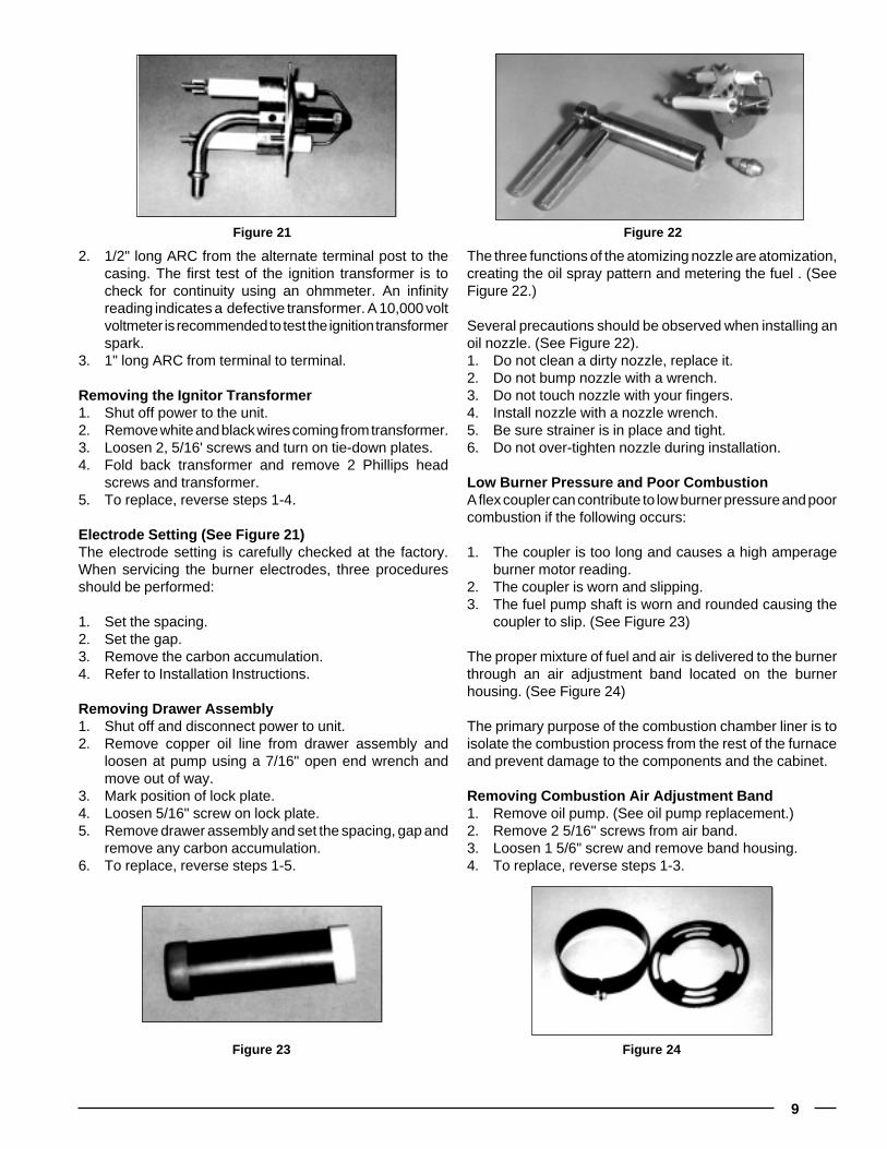
Fan and Limit Switch Combination(See Figure 4)
Testing the Limit Switch (See Figure 5)When testing the limit switch with a voltmeter, a 120V +/-10% reading indicates the switch is open and defective. Thelimit switch should be replaced if cooled below switchsetting.
1. Turn off electrical power to the main power source.2. Disconnect wires from limit switch located inside of
control panel. See wiring diagram, located in controlpanel.
Figure 3
Figure 4
Figure 53. Using an ohmmeter, connect leads to limit switch
terminals.4. If limit switch is below temperature, it will read continuity.
If there is not continuity, replace limit switch by removingtwo 1/4" screws.
Removing the Limit Switch1. Turn power off to the unit.2. Unwire electrical supply.3. Remove 2, 1/4" screws.4. To replace, reverse steps 1-3.*
*Limit switch can be either manual or automatic reset.Manual reset limit will be approved on serial date codesof 9706 and later.
Testing the Fan SwitchThe steps necessary to check the operation of the fan switchin the air circulation circuit are:1. Turn off power to unit.2. Turn voltmeter on and set to scale capable of reading
120V.3. Place leads from voltmeter on both wires of the fan
switch.4. Turn on 120 volt power supply to furnace. Voltmeter
should read 120V ±10%.5. With voltmeter leads still attached set room thermostat
above the room temperature until the burner comes on.6. Watch the dial on the fan switch as the heat exchanger
heats up, the dial should start to rotate. When the fanswitch reaches the on temperature setting the blowershould come on, and 0 volts should be read indicatinga closed switch.
Removing the Fan Switch1. Shut off power to unit.2. Remove cover.3. Disconnect wires.4. Remove 3, 1/4" screws.5. To replace, reverse steps 1-4.
Testing Fan Blower Motor(See Figure 6)1. Check for 120 Volts + 10%.2. Check amperage while unit is running.3. Visually inspect wheel and motor mounting.

5
Removing Blower Motor1. Turn off power to furnace.2. Disconnect power wires.3. Remove two 1/2" screws.4. Slide blower out.5. Remove 3, 3/8" screws.6. Remove blower and blower wheel.7. Remove blower wheel.8. To reinstall, reverse steps 1-7.
Testing The Oil Burner(See Figures 6, 7 and 8)The two manual resets should be checked before testingany other CMF Furnace Component. These are the PrimaryControl and the Burner Motor Manual reset.
Check the incoming power with a voltmeter. Set the voltme-ter at the proper scale, a 120V ±10% should be obtained. Ifnot, check at power cord:
1. Shut off power to the unit.2. Remove Electric Panel Cover 1, 5/16" screw.3. Remove 2 wire nuts.4. Attach voltmeter to incoming power.5. Turn on power to the unit.6. Read voltage 120 +/- 10%.7. Turn off power and reverse steps 1-3.
Test Oil PumpThe fuel(s) used in the oil gun pressure burner applicationsare No. 1 Fuel, and No. 2 Fuel . It is recommended to use #1where temperatures fall below 32°.
The oil storage tank may be installed either above or belowgrade. Check local or state codes. To prevent abnormal tankpressure during fill, the vent pipe should be 1" to 1 1/4" round.On single line systems, bleed all air out of the fuel supplysystem before lighting the furnace.
Test fuel pump resistance or vacuum with a vacuum gauge.If vacuum reads greater than 10 inches, look for kinkedtubing, a plugged oil filter, undersized line, excessive oil lift,heavy oil or a frozen line.
Maximum Values for Vacuum Hq.Single Stage - Single Line(M units) 6"
Single Stage - Two Line(M units) 10"
Two Stage(2 M units) 15"
The second fuel pump test is to check the pump efficiencyor capacity. With the burner running, the efficiency issatisfactory if the oil pressure can be adjusted to 140 PSI.After checks, adjust the oil pressure for normal operationto 100 PSI.
Figure 6
Figure 7
Figure 8

6
Conversion from Natural Gas to Propane
The third fuel pump test is for cut-off. Start the burner andafter a few moments of operation shut off the burner. Uponshutdown, pressure should drop approximately 15 to 20 PSI.The two common reasons for inefficient cut-off on fuelpumps are a defective check valve ball in the pump, or poorconnectors allowing air into the piping system.
Replacing Oil Pump (See Figure 19, page 8)1. Shut off and disconnect power to the unit.2. Shut off oil to pump.3. Remove oil line.4. Using a 7/16" wrench, loosen oil lines from pump open
to drain assembly.5. Remove oil lines from pump and move out of the way.6. Remove 1/4" x 20" x 7/8" hex head screws with 3/8"
open end.7. Pull pump out slowly.8. To replace, reverse steps 1-7.
When installing single-line systems, the only connections onthe burner fuel pump is at the intake port. It is important notto install the “by-pass” plug in the fuel pump return port. Aquick rule which can be used for checking an installation withthe oil storage tank below the fuel pump is to figure:
1. 1" of vacuum for every 10' of horizontal run.2. 1" of vacuum for every 1' of vertical lift.3. 1/2" of vacuum for every 90° elbow fitting.
The single-stage design is used in applications requiring 10"of vacuum or less. Two-stage pumps are specified when upto 15" of vacuum is required. If an oil fuel pump is not properlysized to the vacuum requirements the following will occur:
1. A solid column of oil will not be delivered to the atomizingnozzle.
2. The light portions of the oil will separate from the heavyportion.
3. A milky appearance will be seen in the returned oil.
Figure 9
Figure 10
WARNINGBefore beginning conversion, shut off elec-trical power to the furnace at the main powersource. Shut off gas supply.
!
1. Disconnectiona. Low voltage wiresb. Shut off gas to appliance and remove piping to gas
valve.2 Remove 3, 3/8" bolts from U-shaped manifold plate and
orifice assembly. (See Figure 4, Page 19 )3. Replace alternate fuel orifice. Using a 1/2" open end
wrench, remove the main orifice and replace it with thealternate fuel orifice supplied in the plastic bag with theburner (located with the home owners packet.)
4. Invert the regulator cap. Warning: check for properorifice size listed on furnace rating plate.
5. To reinstall, reverse steps 1-4. Manifold pressure wouldthen be set to 11.0" W.C. for LP gas.
Changing Complete Burner Assembly(See Figures 1, page 18 and Figures 2-4, page 19)1. Open furnace door.2. Using a 7/16" open end wrench, remove three burner
nuts. Remove burner assembly from furnace.3. To replace burner, reverse steps 1 & 2.
NOTE: Be certain to install new gasket.
Remove Burner and/or Ignitor1. Shut off gas supply2. Remove gas lines from Gas valve.3. Unplug ignitor.4. Remove 3, 1/4" screws. Lift burner up and out.5. Remove 1, 1/4" screw and replace ignitor.6. Set gap distance between ignitor and burner head at
1/2" - 5/8." Micro amp signal should be between 2 to4 micro amps (µa).

7
Figure 11
Figure 12
Removal of Air Housing, Blower Wheel and Motor (SeeFigures 14 - 16)1. Shut off power to unit.2. Remove elect wires.3. Remove 4, 1/4" screws (2 on each side of air housing).4. Remove band screw, 5/16" bolt.5. To replace, reverse steps 1-4.
The 3 circuits of the primary control (see Figure 14) are theStarting Circuit, Safety Circuit, and the Running Circuit.
Testing the Primary Control Circuits1. Shut off power to the unit. Close off oil supply.2. Remove thermostat wires from T1 and T2 and cad cell
wires from F1 and F2.3. Turn on power to the unit.4. Jumper out terminals T1 and T2 to test the starting
circuit. The burner should come on and then shut downafter 45 seconds as the safety circuit engages.
Remove Hot Surface Ignition Series(See Figure 12)1. Shut off power to the furnace.2. Remove all wires 24 volt and 120 volt.3. Remove 2, 1/4" screws.4. To remount, reverse steps 1-3.
Removing C Burner Motor (See Figure 4, page 19)1. Shut off power to the furnace.2. Remove wires from HSI control.3. Remove 4, 1/4" screws and HSI control.4. Remove 2, 1/4" screws and panel cover.5. Disconnect wires to motor; 2 red and 2 black.6. Remove 1, 5/8" screw from housing strap and lift off
motor.7. To reinstall, reverse steps 1-6.
Figure 13
Figure 14
Figure 15 Figure 16
8
5. Remove jumper wires and allow two minutes for thesafety heater to cool off.
6. Test running circuit by jumpering out T1 and T2 andreset the primary control. The burner will come on.
7. Immediately jumper F1 and F2 to bypass the cad cell.The burner should run continuously after 45 secondswith the cad cell safety circuit by-passed.
8. Shut off power to the unit, remove all jumpers, and thenreconnect the thermostat and cad cell.
9. If any one of these test fails, replace the primary control.
Removing the Primary Control1. Shut off power to the unit.2. Open ignition transformer by removing 2 5/16" screws.3. Remove the black, white and orange wires leading from
the primary control.4. Remove cad cell wires from F1 and F2, and remove
thermostat wires from T1 and T2.5. Loosen 2, 1/4" screws and remove primary control.6. To replace, reverse steps 1-5.
Testing Cad CellThe cad cell is a light sensing resistor. Its function is to cutpower to the burner motor in the event the electrodes fail toestablish flame.
To check the CAD cell start the burner and unhook both cadcell leads from the FF terminals on the primary control. Afterthe burner lights jump the FF terminals to keep the burnerrunning. Measure the ohms resistance across the cad celllead as it views the flame. This should be 1,600 ohms or less.A preferred reading is 300-1000 ohms. Next, with the meterstill connected to the cad cell leads, turn the burner OFF. The
dark condition should give a reading of 100,000 ohms orinfinity. If the reading is lower, let the refractory cool down orlook for stray light that might be entering the burner throughthe air inlet, or around the transformer base plate. If the cadcell is not performing within these guidelines, replace it.
Removing the Cad Cell (See Figures 17 and 18)1. Shut off power to the unit.2. Remove wires from primary control.3. Open ignition transformer.4. Turn cad cell 1/2 turn in retainer and lift out.5. To replace, reverse steps 1-4.
Testing Ignition Transformer (See Figure 20)
Figure 17
Figure 18
WARNINGIn testing the ignition transformer extremecaution should be exercised because 10,000 to14,000 volts are present.
!
Figure 19 Figure 20
The most common field test of the ignition transformationspark is using a service test cord connected to the primarywinding wiring and an INSULATED screw driver. The testsshould indicate an arc:
1. 1/2" long ARC from the terminal post to the casing.
9
The three functions of the atomizing nozzle are atomization,creating the oil spray pattern and metering the fuel . (SeeFigure 22.)
Several precautions should be observed when installing anoil nozzle. (See Figure 22).1. Do not clean a dirty nozzle, replace it.2. Do not bump nozzle with a wrench.3. Do not touch nozzle with your fingers.4. Install nozzle with a nozzle wrench.5. Be sure strainer is in place and tight.6. Do not over-tighten nozzle during installation.
Low Burner Pressure and Poor CombustionA flex coupler can contribute to low burner pressure and poorcombustion if the following occurs:
1. The coupler is too long and causes a high amperageburner motor reading.
2. The coupler is worn and slipping.3. The fuel pump shaft is worn and rounded causing the
coupler to slip. (See Figure 23)
The proper mixture of fuel and air is delivered to the burnerthrough an air adjustment band located on the burnerhousing. (See Figure 24)
The primary purpose of the combustion chamber liner is toisolate the combustion process from the rest of the furnaceand prevent damage to the components and the cabinet.
Removing Combustion Air Adjustment Band1. Remove oil pump. (See oil pump replacement.)2. Remove 2 5/16" screws from air band.3. Loosen 1 5/6" screw and remove band housing.4. To replace, reverse steps 1-3.
2. 1/2" long ARC from the alternate terminal post to thecasing. The first test of the ignition transformer is tocheck for continuity using an ohmmeter. An infinityreading indicates a defective transformer. A 10,000 voltvoltmeter is recommended to test the ignition transformerspark.
3. 1" long ARC from terminal to terminal.
Removing the Ignitor Transformer1. Shut off power to the unit.2. Remove white and black wires coming from transformer.3. Loosen 2, 5/16' screws and turn on tie-down plates.4. Fold back transformer and remove 2 Phillips head
screws and transformer.5. To replace, reverse steps 1-4.
Electrode Setting (See Figure 21)The electrode setting is carefully checked at the factory.When servicing the burner electrodes, three proceduresshould be performed:
1. Set the spacing.2. Set the gap.3. Remove the carbon accumulation.4. Refer to Installation Instructions.
Removing Drawer Assembly1. Shut off and disconnect power to unit.2. Remove copper oil line from drawer assembly and
loosen at pump using a 7/16" open end wrench andmove out of way.
3. Mark position of lock plate.4. Loosen 5/16" screw on lock plate.5. Remove drawer assembly and set the spacing, gap and
remove any carbon accumulation.6. To replace, reverse steps 1-5.
Figure 21 Figure 22
Figure 24Figure 23

10
Removing Motor and Blower Wheel1. Shut off power to the unit.2. Open transformer.3. Remove motor wire.4. Remove 2, 3/8" screws.5. Remove motor and blower wheel.6. Loosen 1/8" Allen screw and remove wheel. The wheel
will be down 3/4" on the shaft.7. To replace, reverse steps 1-6. (See Figure 9, page 6
and Figure 16, page 7)
Installation Instructions CB-200A BaseThe model CB-200A (901696) base allows for a non-sealedcombustion, central heating (without warm air ducts) instal-lation of the CMF Series furnaces. This installation must bedone by a qualified installing agency in accordance withlocal codes and ordinances.
LocationAllow clearance from adjacent materials as stated under“Minimum Clearances.” Ample clearance should be pro-vided to permit easy access for removal of filters, blower,motors, controls and vent connections. Unit must beinstalled in a level position on NORDYNE base modelCB-200A.
Minimum Clearances To Adjacent MaterialsThe furnace may be installed in a corner, or against an openwall with the clearances not less than: Front 36 inches; Top17 inches; Vent 9* inches for oil units, 6 inches for gas units;3* inches for rear; and 2** inches for one side if in corner.
* Rear clearance may be 0 inches but vent clearance will bereduced to 6 inches. Refer to table 8, appendix B of NFBANo. 31 for requirements to achieve 6 inches vent clearance.
** The minimum clearance from warm air register in basemust be 36 inches. Use a 15 5/8" L x 7" W sheet metal blankoff panel to replace register when clearance is less than 36inches.
Venting (CB-200A Base)Unit must be vented through a permanent chimney or 4"type L, low temperature venting system (oil units) or 4" typeBW venting system (gas units) selected and installed by theinstaller. Check chimney for soot, leaks, obstructions andproper height. If it is necessary to construct a new chimney,local conditions such as necessary height, draft, and num-ber of appliances served should be checked with localbuilding codes.
Horizontal distances to an existing chimney should be asshort as possible and the connecting pipe should slopeupward to the chimney at not less than a 45° angle. Totallength of the sloping pipe must not exceed 6 feet.
Barometric regulator (oil units)* is to be installed at the ventconnection of the furnace. All flue pipe joints should befastened with sheet metal screws for rigidity.
To prevent down-draft, the chimney should extend at least2' above the peak of roof. The internal area of the chimneyshould equal the area of the flue outlet on the furnace. Thechimney should have no obstructions or sharp bends wheresoot and other foreign matter can accumulate. If inspectionshows it to be obstructed, the chimney should be cleaned.The existing flue pipe should be cleaned or a new pipeshould be installed. Connect the flue pipe to the chimney withfew elbows as possible. Do not install hand dampers of anytype.
It is desirable that the furnace flue serves no other appli-ances. However, when two or more appliances must ventinto a common flue, the area of the common flue should atleast equal the area of the largest flue connector, plus 50%of the area of the additional flue and vent connectors. Theflue or vent connector must be inserted into, but not beyond,the inside wall of the chimney flue liner.
Provisions must be made for adequate ventilation to prop-erly support combustion and to maintain safe ambient tem-peratures.
When buildings are so tight that normal infiltration does notmeet air requirements, one or more permanent openingsmust be provided to supply outside air. The minimum crosssection of the duct is to be 1 sq. inch area-free for each 2000Btuh input for horizontal duct installations, or 4000 Btuh inputfor vertical installations. Refer to gas code book.
InstallationBase: The base must be located on a hard surface. Whenthe furnace location is carpeted, use a hard surface platformunder the base.
Furnace: Set the furnace on the base without damaging thefoam gasket material on the base top. Making sure thefurnace is seated on the back of the base, fasten the front ofthe furnace to the base with 1/2" long sheet metal screws.
NOTE: Front register is not adjustable and remains fullyopen.
Fuel line piping, wiring, and thermostat: Refer to the instal-lation and operation manuals provided with the furnace.
DANGER: When using CB-200 A (Cottage Base), do notinstall the furnace in a mobile home. Do not install thefurnace in a closet, alcove or other enclosed area.Violation of the above may cause incomplete combus-tion which may produce poisonous gases causing as-phyxiation and resulting in sickness or death.

11
Conduct Draft Test
Conduct Flue GasTemperature Test
ConductCO2 Test
Testing Combustion EfficiencyWith Bacharach Test Kit
ConductSmoke Test
Take SampleAt Hole in FlueAnd Compare
To Smoke Sale
Test at Hole in Flue. AdjustAir Band for Highest CO2Reading (With 0 to 1 Trace
Smoke Reading) Within 10 1/2%to 11%. Operate Unit 15 Minutes
Before Final Adjustments
ConductOver-FireDraft Test
CalculateCombustion
Efficiency
Set HorizontalScale on
Efficiency Finder to Correct Net Stack
Temperature
Set Green ArrowOn Vertical
Scaleto % CO2
ReadCombustionEfficiency
and Stack Loss
Defective orBlocked
Chimney
Leak inSmoke Pipe
Over -.035 WC
Soot in HeatExchanger
Too Short Draft Stack
Soot in Heat
Exchanger
Too Short or
Wrong Flue
Stack DraftOver
.05" WC
Stack Draft +.02" to +.04" WC
Less-.01"WC Over Fire
Draft
Over-.03 WC
Over FireDraft
Excess AirSet Too High
Oil onSmoke
Disc
Air Leaksin Furnace
Air ShutterOpen
Too Wide
FaultyNozzle
OperationFaultyNozzle
Operation Faulty Combustion
ChamberPoor Combustion
Chamber
Poor Combustion
Chamber
Excessive Draft
No Smoke on Disc
CO2 Low,Under
10 1/2%
CO2 High,Over 11%
Under FiringCombustion
Chamber
NozzleToo Small
Air Leaksin Furnace
Air BandOpen Too
Wide
Air BandAdjustment
Tighten AirBand Screws
Air BandClosed
Too Much
Dirty Fanor Air
HandlingParts
UnderfiringFurnace
Turn T’Stat to Highest Thermostat Setting.Allow 5 Minutes of Operation.
Drill 1/4" Hole on Flue
ExcessiveDraft
Baffles Burnt Out in
Heat Exchanger
OverfiringFurnace
DirtyHeat
Exchanger
DirtyHeat
Exchanger CalculateNet Stack
Temperature
Test at Hole in Flue.Allow Thermostat
Needleto Stabilize
Adjust Draft Gaugeto Zero.
Test at Hole in Flue
Over 630˚F
Under380˚F
Too Little Draft
Over 11%
Under10 1/2 %
BurnerOverfiring
Over 2Spots
Less Than1 Spot
Overfiringof Unit
Oil Rate Too High
Too LittleExcess Air
Dirty Fanor Air
Handling Parts
Poor NozzleOperation
Defective or Improperly
Installed Flue
Plug 1/4"Hole in Flue
Test AtInspection Door
Above Burner
Pressure Dropof +.005" to+.015" WC
Over Fire Draftof -.01" to-.03" WC
Good
Less Than-.025" WC
Defective or Blocked Chimney
Leak inSmoke
Pipe
Air BandAdjustment
WithLow
Smoke
WithHigh
Smoke
#1 #2 #3 #4 #5 #6 #7
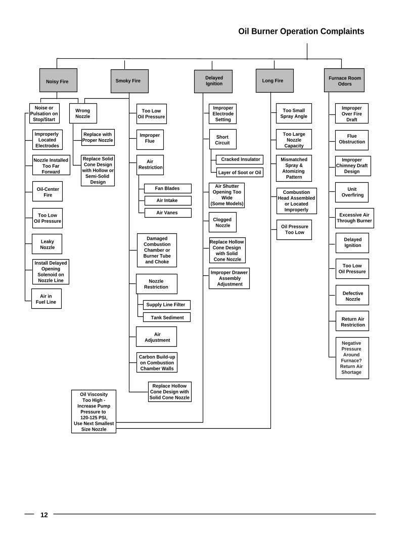
12
Replace HollowCone Design
with Solid Cone Nozzle
Noisy Fire Smoky FireDelayedIgnition
Oil Burner Operation Complaints
Long Fire Furnace RoomOdors
DamagedCombustionChamber orBurner Tubeand Choke
ImproperElectrode
Setting
ShortCircuit
Too LowOil Pressure
LeakyNozzle
Air inFuel Line
Replace withProper Nozzle
Too LowOil Pressure
ImproperFlue
Install DelayedOpening
Solenoid onNozzle Line Nozzle
Restriction
Supply Line Filter
Fan Blades
Cracked Insulator
Layer of Soot or Oil
Air Intake
Air Vanes
Tank Sediment
AirAdjustment
Carbon Build-upon CombustionChamber Walls
Replace HollowCone Design withSolid Cone Nozzle
Air Restriction
WrongNozzle
Improperly Located
Electrodes
Nozzle InstalledToo FarForward
Oil-CenterFire
Clogged Nozzle
Improper Drawer Assembly
Adjustment
Air ShutterOpening Too
Wide(Some Models)
Too LargeNozzle
Capacity
MismatchedSpray &
Atomizing Pattern
CombustionHead Assembled
or LocatedImproperly
Oil PressureToo Low
Too SmallSpray Angle
FlueObstruction
ImproperChimney Draft
Design
Unit Overfiring
Excessive AirThrough Burner
DelayedIgnition
Too LowOil Pressure
DefectiveNozzle
Return AirRestriction
ImproperOver Fire
Draft
Replace SolidCone Design
with Hollow orSemi-Solid
Design
Oil ViscosityToo High -
Increase PumpPressure to 120-125 PSI,
Use Next SmallestSize Nozzle
Noise orPulsation on
Stop/Start
Negative Pressure Around
Furnace?Return Air Shortage
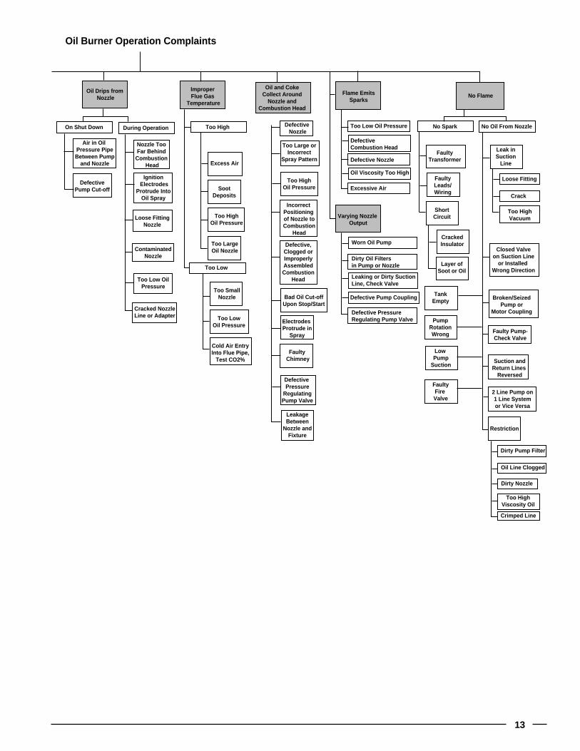
13
Oil Drips from Nozzle
ImproperFlue Gas
Temperature
Oil and CokeCollect Around
Nozzle andCombustion Head
Oil Burner Operation Complaints
Flame EmitsSparks
Ignition Electrodes
Protrude IntoOil Spray
Loose FittingNozzle
Too Low OilPressure
SootDeposits
Excess Air
Too HighOil Pressure
ContaminatedNozzle
Too Low
Too High
Too LargeOil Nozzle
Air in Oil Pressure PipeBetween Pump
and Nozzle
DefectivePump Cut-off
Nozzle TooFar Behind
Combustion Head
ShortCircuit
FaultyTransformer
CrackedInsulator
Leak inSuction
Line
Closed Valveon Suction Line
or Installed Wrong Direction
Broken/SeizedPump or
Motor Coupling
Faulty Pump-Check Valve
Suction andReturn Lines
Reversed
FaultyLeads/Wiring
On Shut Down During Operation
2 Line Pump on1 Line Systemor Vice Versa
Restriction
Layer ofSoot or Oil
TankEmpty
PumpRotationWrong
Low Pump
Suction
FaultyFire Valve
Too LowOil Pressure
Too SmallNozzle
Cold Air EntryInto Flue Pipe,
Test CO2%
Cracked NozzleLine or Adapter
No Spark No Oil From Nozzle
Too HighOil Pressure
IncorrectPositioning of Nozzle to Combustion
Head
Bad Oil Cut-offUpon Stop/Start
Defective,Clogged orImproperlyAssembledCombustion
Head
Too Large orIncorrect
Spray Pattern
Defective Nozzle
Too Low Oil Pressure
DefectiveCombustion Head
Defective Nozzle
Oil Viscosity Too High
Excessive Air
Loose Fitting
Crack
Too HighVacuum
Dirty Oil Filtersin Pump or Nozzle
Worn Oil Pump
Leaking or Dirty SuctionLine, Check Valve
Defective Pump Coupling
Defective PressureRegulating Pump Valve
Oil Line Clogged
Dirty Pump Filter
Dirty Nozzle
Too HighViscosity Oil
Crimped Line
Electrodes Protrude in
Spray
Faulty Chimney
LeakageBetween
Nozzle andFixture
Defective Pressure
RegulatingPump Valve
No Flame
Varying Nozzle Output

14
Oil Gas
Testing Faulty Fuel Delivery
Faulty or Clogged
Combustion Head & Nozzle
Faulty Fuel Pump
LineRestriction
Wrong Typeof Fuel
Leak inSuction
Line
KinkedTubing
Shut OffValve
Closed
Leaking orDirty Suction
Line,Check Valve
CloggedOil
PumpStrainer
Sediment inTank,
Contaminated Oil
Faulty Installation
CloggedSupply
Line Filter
Defective, Clogged or
WrongNozzle
Kinked Tubing
Wrong Orifice
Clogged Orifice
Shut Off Valve Closed
Defective Gas Valve
Improper Pressure Input, Output
Restricted CombustionAir Intake
Crack
Loose Fitting
Too High Vacuum,Excessive Lift
Restriction, Kink, Etc.
Shut Off ValveInstalled in
Wrong Direction
2 Line Pump on1 Line Systemor Vice Versa
Improper Venting of
Tank
Undersized Tubing
Too LongTubing Run,Excessive
Oil Lift
By-Pass PlugInstalled in Return Port
Suction andReturn Lines
Reversed
Empty Tank
Air in Line
Loose Supply Line Connections
Test Burner Motor
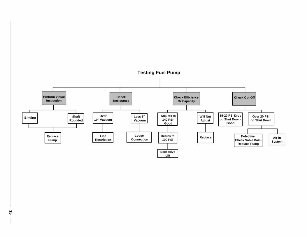
15
Perform VisualInspection
CheckResistance
Testing Fuel Pump
Check EfficiencyOr Capacity
ShaftRounded
Binding
ReplacePump
LineRestriction
Check Cut-Off
Less 6" Vacuum
Over10" Vacuum
Loose Connection
Return to100 PSI
Will NotAdjust
Adjusts to140 PSI-
Good
Replace Defective Check Valve Ball -
Replace Pump
Over 20 PSIon Shut Down
15-20 PSI Dropon Shut Down-
Good
Air inSystem
ExcessiveLift
16
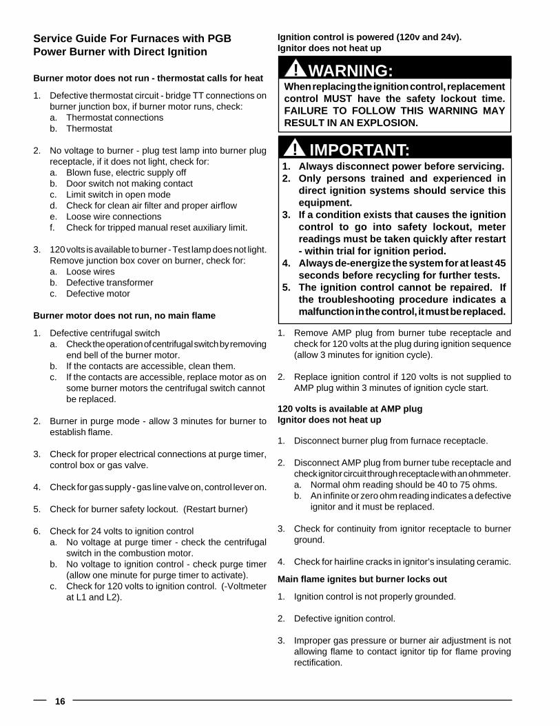
Service Guide For Furnaces with PGBPower Burner with Direct Ignition
Burner motor does not run - thermostat calls for heat
1. Defective thermostat circuit - bridge TT connections onburner junction box, if burner motor runs, check:a. Thermostat connectionsb. Thermostat
2. No voltage to burner - plug test lamp into burner plugreceptacle, if it does not light, check for:a. Blown fuse, electric supply offb. Door switch not making contactc. Limit switch in open moded. Check for clean air filter and proper airflowe. Loose wire connectionsf. Check for tripped manual reset auxiliary limit.
3. 120 volts is available to burner - Test lamp does not light.Remove junction box cover on burner, check for:a. Loose wiresb. Defective transformerc. Defective motor
Burner motor does not run, no main flame
1. Defective centrifugal switcha. Check the operation of centrifugal switch by removing
end bell of the burner motor.b. If the contacts are accessible, clean them.c. If the contacts are accessible, replace motor as on
some burner motors the centrifugal switch cannotbe replaced.
2. Burner in purge mode - allow 3 minutes for burner toestablish flame.
3. Check for proper electrical connections at purge timer,control box or gas valve.
4. Check for gas supply - gas line valve on, control lever on.
5. Check for burner safety lockout. (Restart burner)
6. Check for 24 volts to ignition controla. No voltage at purge timer - check the centrifugal
switch in the combustion motor.b. No voltage to ignition control - check purge timer
(allow one minute for purge timer to activate).c. Check for 120 volts to ignition control. (-Voltmeter
at L1 and L2).
1. Remove AMP plug from burner tube receptacle andcheck for 120 volts at the plug during ignition sequence(allow 3 minutes for ignition cycle).
2. Replace ignition control if 120 volts is not supplied toAMP plug within 3 minutes of ignition cycle start.
120 volts is available at AMP plugIgnitor does not heat up
1. Disconnect burner plug from furnace receptacle.
2. Disconnect AMP plug from burner tube receptacle andcheck ignitor circuit through receptacle with an ohmmeter.a. Normal ohm reading should be 40 to 75 ohms.b. An infinite or zero ohm reading indicates a defective
ignitor and it must be replaced.
3. Check for continuity from ignitor receptacle to burnerground.
4. Check for hairline cracks in ignitor’s insulating ceramic.
Main flame ignites but burner locks out
1. Ignition control is not properly grounded.
2. Defective ignition control.
3. Improper gas pressure or burner air adjustment is notallowing flame to contact ignitor tip for flame provingrectification.
Ignition control is powered (120v and 24v).Ignitor does not heat up
When replacing the ignition control, replacementcontrol MUST have the safety lockout time.FAILURE TO FOLLOW THIS WARNING MAYRESULT IN AN EXPLOSION.
WARNING:!
1. Always disconnect power before servicing.2. Only persons trained and experienced in
direct ignition systems should service thisequipment.
3. If a condition exists that causes the ignitioncontrol to go into safety lockout, meterreadings must be taken quickly after restart- within trial for ignition period.
4. Always de-energize the system for at least 45seconds before recycling for further tests.
5. The ignition control cannot be repaired. Ifthe troubleshooting procedure indicates amalfunction in the control, it must be replaced.
IMPORTANT:!
17
24 volts supplied to gas valve during ignition but nomain gas flow1. Gas valve may be defective. Replace if necessary.2. Gas piping may be plugged. Check for adequate gas
supply to gas valve at union.
Burner operates, insufficient heat1. Check the thermostat for proper setting and location.
The thermostat should not be located where it will beaffected by another heat source. (Lamps, ovens,sunlight, etc.)
2. Check for clean air filters and proper air flow.3. Check burner for proper gas firing rate.4. Be sure unit is not undersized for its thermal load.5. Check thermostat anticipator. (0.9 amps)
Burner does not shut offNote: Burner will stop when the door switch is open. Withthe door open, secure the door switch in the closed positionby depressing the switch. The means for securing the doorswitch must be removed once this testing has been com-pleted.
1. Disconnect the thermostat wires from TT connectionson the burner junction box. If the burner shuts off, checkfor:a. Short circuit in the thermostat wires.b. Defective thermostat.
Burner flame without motor runningGas valve is stuck in open position - Replace the control,burner and heat exchanger may need cleaning.
Noisy fireReadjust combustion air to reduce volume of air being drawninto the burner. (Caution: See burner adjustment)
High Gas Bills1. Check the combustion air adjustment.
2. Be sure the proper size orifice is being used.
3. Be sure the return air filter is clean.
4. Be sure the home is insulated, windows and doors fittightly, and there are no air leaks in the heating ducts.
5. Check room thermostat to be sure the setting is nothigher than necessary. Low humidity requires highertemperatures for comfort. Perhaps humidity should beincreased.
Circulation blower will not operate even though theburner operates1. Turn on the manual blower switch. If the blower operates,
check the fan switch.
2. Check the wiring to the motor.
3. Check for a burned out motor.

18
CMF Oil to Gas Conversion
WARNING:!This furnace must be installed by a qualifiedinstalling agency and in accordance with localcodes and ordinances. Failure to properly installthe furnace, base assembly and venting systemas described herein may damage the equipmentand/or the home, can create a fire or asphyxiationhazard, violates U.S. listing requirements, andwill void the warranty. This furnace is NOTapproved for installation with split system airconditioning. Use a NORDYNE packaged airconditioning system.
FOR YOUR SAFETY:!Do not store gasoline or other flammable vaporsand liquids in the vicinity of this or any otherappliance.
WARNING:!Improper installation, alteration, service ormaintenance can cause injury or propertydamage. Refer to this manual. For assistance oradditional information consult a qualifiedinstaller, service agency, or the gas supplier.
Figure 1.
Before installing the power gas burner, removal of presentburner is required. (See Figure 2.)
1. Shut off electric power supply to furnace. Removepower cord from 120v receptacle, remove low voltage(thermostat) wiring from primary control connections.
2. Shut off fuel supply to burner, close line or tank valve ifapplicable. Disconnect fuel line at inlet fitting on burnerpump and remove fuel line.
3. Loosen and remove the three (3) 2/16" hex nuts, andremove the burner.
4. Inspect the combustion chamber and heat exchangerfor cracks, corrosion, or soot. If signs of sooting arepresent, the heat exchanger should be cleaned to insureproper draft.
Installing Gas Burner
1. Place new burner gasket on mounting plate. (See Figure3.) Insert burner tube into heat exchanger throughmounting flange. Mount burner on studs, making sureburner will pull up tight to flange, and fasten to mountingflange using the three hex nuts.
2. Reconnect thermostat leads to appropriate connectionson burner. Attached power cord may then be pluggedinto 120v receptacle.
3. Connect gas piping and check for leaks.a. Gas piping should be sized and installed in accordancewith local codes and utility regulations.
4. Thermostat - It may be necessary to change the heatanticipator setting. Failure to do so could result in a widetemperature fluctuation in home.
FOR YOUR SAFETY:!WHAT TO DO IF YOU SMELL GAS� Do not try to light any electrical switch; do
not use any phone in your building.� Immediately call your gas supplier from a
neighbor's phone. Follow gas supplier'sinstructions.
� If you cannot reach your gas supplier, callthe fire department.
19
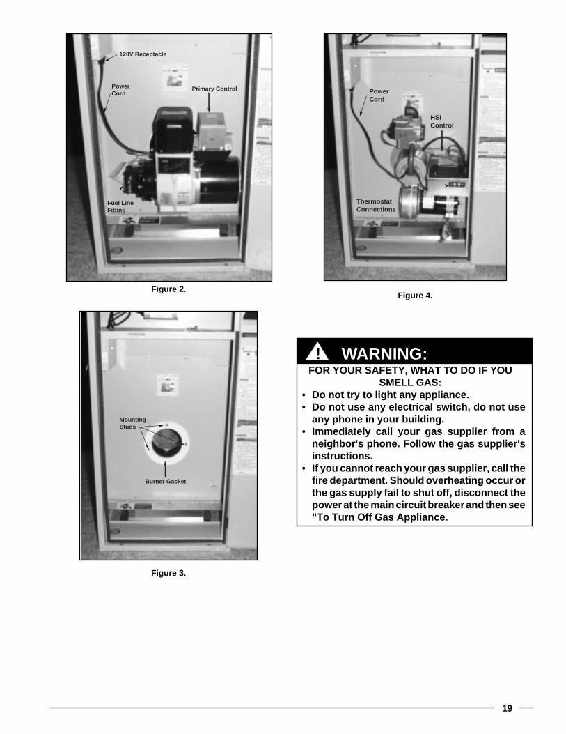
Figure 4.
FOR YOUR SAFETY, WHAT TO DO IF YOUSMELL GAS:
� Do not try to light any appliance.� Do not use any electrical switch, do not use
any phone in your building.� Immediately call your gas supplier from a
neighbor's phone. Follow the gas supplier'sinstructions.
� If you cannot reach your gas supplier, call thefire department. Should overheating occur orthe gas supply fail to shut off, disconnect thepower at the main circuit breaker and then see"To Turn Off Gas Appliance.
WARNING:!
Figure 2.
120V Receptacle
Primary ControlPowerCord
Fuel LineFitting
HSIControl
PowerCord
ThermostatConnections
Figure 3.
MountingStuds
Burner Gasket
20
Operation — CMF-PG SeriesFOR YOUR SAFETY READ BEFORE LIGHTING OROPERATING.
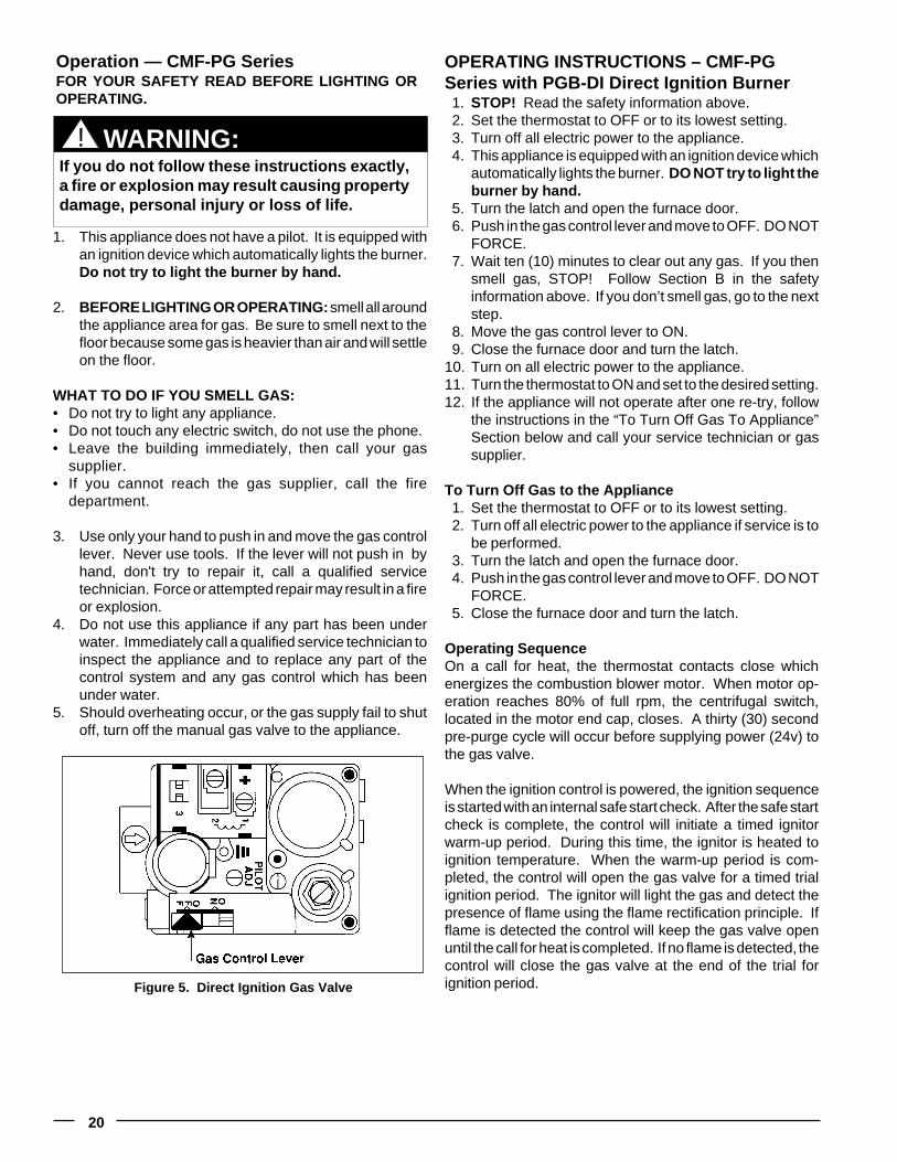
1. This appliance does not have a pilot. It is equipped withan ignition device which automatically lights the burner.Do not try to light the burner by hand.
2. BEFORE LIGHTING OR OPERATING: smell all aroundthe appliance area for gas. Be sure to smell next to thefloor because some gas is heavier than air and will settleon the floor.
WHAT TO DO IF YOU SMELL GAS:• Do not try to light any appliance.• Do not touch any electric switch, do not use the phone.• Leave the building immediately, then call your gas
supplier.• If you cannot reach the gas supplier, call the fire
department.
3. Use only your hand to push in and move the gas controllever. Never use tools. If the lever will not push in byhand, don't try to repair it, call a qualified servicetechnician. Force or attempted repair may result in a fireor explosion.
4. Do not use this appliance if any part has been underwater. Immediately call a qualified service technician toinspect the appliance and to replace any part of thecontrol system and any gas control which has beenunder water.
5. Should overheating occur, or the gas supply fail to shutoff, turn off the manual gas valve to the appliance.
WARNING:If you do not follow these instructions exactly,a fire or explosion may result causing propertydamage, personal injury or loss of life.
!
Figure 5. Direct Ignition Gas Valve
OPERATING INSTRUCTIONS – CMF-PGSeries with PGB-DI Direct Ignition Burner1. STOP! Read the safety information above.2. Set the thermostat to OFF or to its lowest setting.3. Turn off all electric power to the appliance.4. This appliance is equipped with an ignition device which
automatically lights the burner. DO NOT try to light theburner by hand.
5. Turn the latch and open the furnace door.6. Push in the gas control lever and move to OFF. DO NOT
FORCE.7. Wait ten (10) minutes to clear out any gas. If you then
smell gas, STOP! Follow Section B in the safetyinformation above. If you don’t smell gas, go to the nextstep.
8. Move the gas control lever to ON.9. Close the furnace door and turn the latch.
10. Turn on all electric power to the appliance.11. Turn the thermostat to ON and set to the desired setting.12. If the appliance will not operate after one re-try, follow
the instructions in the “To Turn Off Gas To Appliance”Section below and call your service technician or gassupplier.
To Turn Off Gas to the Appliance1. Set the thermostat to OFF or to its lowest setting.2. Turn off all electric power to the appliance if service is to
be performed.3. Turn the latch and open the furnace door.4. Push in the gas control lever and move to OFF. DO NOT
FORCE.5. Close the furnace door and turn the latch.
Operating SequenceOn a call for heat, the thermostat contacts close whichenergizes the combustion blower motor. When motor op-eration reaches 80% of full rpm, the centrifugal switch,located in the motor end cap, closes. A thirty (30) secondpre-purge cycle will occur before supplying power (24v) tothe gas valve.
When the ignition control is powered, the ignition sequenceis started with an internal safe start check. After the safe startcheck is complete, the control will initiate a timed ignitorwarm-up period. During this time, the ignitor is heated toignition temperature. When the warm-up period is com-pleted, the control will open the gas valve for a timed trialignition period. The ignitor will light the gas and detect thepresence of flame using the flame rectification principle. Ifflame is detected the control will keep the gas valve openuntil the call for heat is completed. If no flame is detected, thecontrol will close the gas valve at the end of the trial forignition period.

21
Figure 6. Air Shutter Adjustments forPower Gas Burner
The ignition control is equipped with a relight feature. If theflame is extinguished during the run cycle, the control willclose the gas valve and repeat the ignition sequence aspreviously described. Once in lockout, the control can bereset by interrupting the 24 VAC power. This can be easilyaccomplished by setting the thermostat below room tem-perature for at least forty-five (45) seconds, and then return-ing it to desired setting.
If adjusting the thermostat does not reset the ignition control,turn power to the appliance off for forty-five (45) seconds,and then turn it back on.
NOTE: If the gas control has been replaced or serviced,lighting may not be satisfactory until air has been purgedfrom the gas line or the gas input and combustion air havebeen adjusted.
Checking Natural Gas InputCheck the label on the burner to be sure the burner isequipped with orifices for type of gas being used. Alternateorifices are in bag attached to the burner. Instructions forchanging orifices are covered later herein.
To check the input, time the dial on the meter for onerevolution while the burner is operating. Be sure to isolateall other gas consuming appliances except pilots. If the timevaries more than 5% from the times shown on the chart,check the gas pressure according to the procedure stated inGAS BURNER CONTROLS. If the pressure readingmatches the pressure shown on the chart; check to be surethe proper burner orifice is being used. Further gas prob-lems should be referred to the local gas supplier. Natural gasvaries in BTU value from 950 to 1,050 BTU per cubic foot.The chart is based on natural gas at an average of 1,000BTU per cubic foot, burner manifold pressure of 3.5" W.C.and meter dial size of 1 cubic foot.
Adjusting the Burner1. Air shutters are factory preset for installation in a given
furnace. (See Figure 15) Local conditions may requirefine tuning. Rotate the air shutter disc at the left of theburner housing to adjust the combustion air. Rotate thedisc counterclockwise to increase combustion air. Rotatethe disc clockwise to decrease combustion air.
The combustion air for the power gas burner is taken fromthe outside of the manufactured home.
Operating at high altitudes — for operation at elevationsof more than 2,000 feet above sea level, the input should bede-rated 4% for each 1,000 feet above sea level by reducingorifice size, or decreasing the manifold pressure.1. Observe combustion flame through observation door on
CMF series furnaces immediately after burner is placedin operation. Yellow flame tips should be visible abovecombustion chamber.
2. Burner should run quietly. Excessive updraft may causeburner to rumble; rotate disc to decrease air supply.(CAUTION: See Note below.)
3. After checking the flame pattern and for noise level, lockdisc in position by tightening slotted head screw.
NOTE: It is very important that air supply be ample withoutdecreasing efficiency of burner. An inadequate amount ofair can cause carbon monoxide (CO). The carbon dioxide(CO
2) content of the flue products should be in the range of
8.0 to 9.0 percent for natural gas and 9.0 to 10.0 percent forLP gas.
Adjusting Heat Distribution1. Set the room thermostat for the desired room
temperature.2. Balance the heat distribution by adjusting the register
openings.
Checking LP Gas InputLP gas installations are not usually supplied with meters fordetermining the amount of gas used. The chart shows theapproximate time required per dial revolution if a meter isused that is calibrated for cubic feet delivery. The chart isbased on LP gas at an average of 2,500 BTU per cubic foot,burner manifold pressure of 10" W.C. and meter dial size of1 cubic foot.
Burner BTUH Burner Time PerModel Input Orifice Rev.PGB-1 90,000 No. 16 40 sec.PGB-2 75,000 No. 20 47 sec.
Table 1.
Burner BTUH Burner Time PerModel Input Orifice Rev.PGB-1 90,000 No. 36 98 sec.PGB-2 75,000 No. 40 117 sec.
Table 2.
PGB Basic Air ShutterSettings
To check combustionair openings: Insert airguage vertically into theblower, the gaugeshould stop within therange shown in thechart. Make sure theshutter is securelylocked. See InstallationManual.
Burner Model Air SettingPGB-1 GPGB-2 DPGB-3 C
LOCKING SCREW
22
Reassemble Appliance:1. Reassemble the burner assembly into the furnace.2. Reconnect the gas piping and electrical wires to the gas
valve.3. Open the manual shut-off valve and follow the “Operating
Instructions” as outlined previously in this manual to putthe furnace into operation.
Centrifugal SwitchThe electric motor for the blower which supplies combustionair to the burner is equipped with a centrifugal switch wiredin series with the burner controls. This switch is normallyopen until the speed of the blower motor closes it therebypowering the burner controls. The burner controls will notfunction until the blower motor is operating at full speed.
Firing Rate ConversionThe rated firing rates of the CMF80 convertible furnaces(PO & PG) can be adjusted from the factory setting of75,000 BTU/hr.
The firing rate can be changed to either 65,000 BTU/hr. or to90,000 BTU/hr. using the appropriate certified NORDYNEconversion kit installed by a NORDYNE distributor or Ser-vice PRO. See the Replacement Parts Listing for the appro-priate kit number to order.
Air Supply for Sealed Combustion1. Close and latch burner access door to complete the
outdoor combustion air passage.2. If the space below the home is enclosed, be sure a vent
or duct of at least 18 square inches of free area isprovided from the outside to provide sufficient air forcombustion. Make sure the combustion air duct extendsthrough the floor and is unobstructed.
Gas Burner Controls (Direct Ignition Series)Combination Electric Gas Valve andPressure RegulatorThe combination electric gas valve and pressure regulatorperforms several functions. The gas valve control lever hastwo positions. The OFF position completely shuts off the gassupply. The ON position allows gas flow through theredundant gas valve when it is energized electrically.
Gas to LP ConversionThis gas fired heating appliance was shipped from thefactory for use with natural gas. However, the appliance canbe converted to be used with LP gas. Use the followingprocedure for gas conversion of the burner.
Remove the Burner Assembly:1. Follow instructions “To Turn Off Gas To Appliance.”2. Shut off gas supply at meter.3. Disconnect gas burner electric cord, gas piping to burner,
and thermostat leads.4. Remove three (3) hexagon nuts holding burner in place.
Change the Main Burner Orifice:1. Disconnect inlet pipe union at burner. Disconnect
burner power cord.2. Disconnect the two wires leading to gas control valve.3. Remove three (3) bolts from U-shaped manifold plate
and orifice assembly.4. Remove the main orifice and replace it with the alternate
fuel orifice supplied in the plastic bag with this burner.
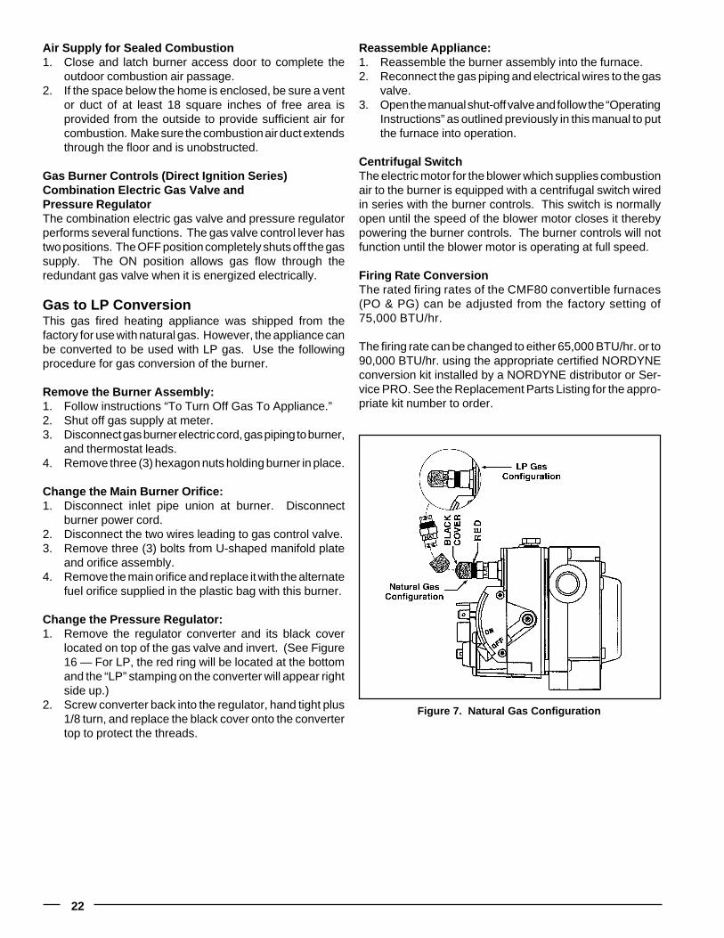
Change the Pressure Regulator:1. Remove the regulator converter and its black cover
located on top of the gas valve and invert. (See Figure16 — For LP, the red ring will be located at the bottomand the “LP” stamping on the converter will appear rightside up.)
2. Screw converter back into the regulator, hand tight plus1/8 turn, and replace the black cover onto the convertertop to protect the threads.
Figure 7. Natural Gas Configuration
23
Gas G
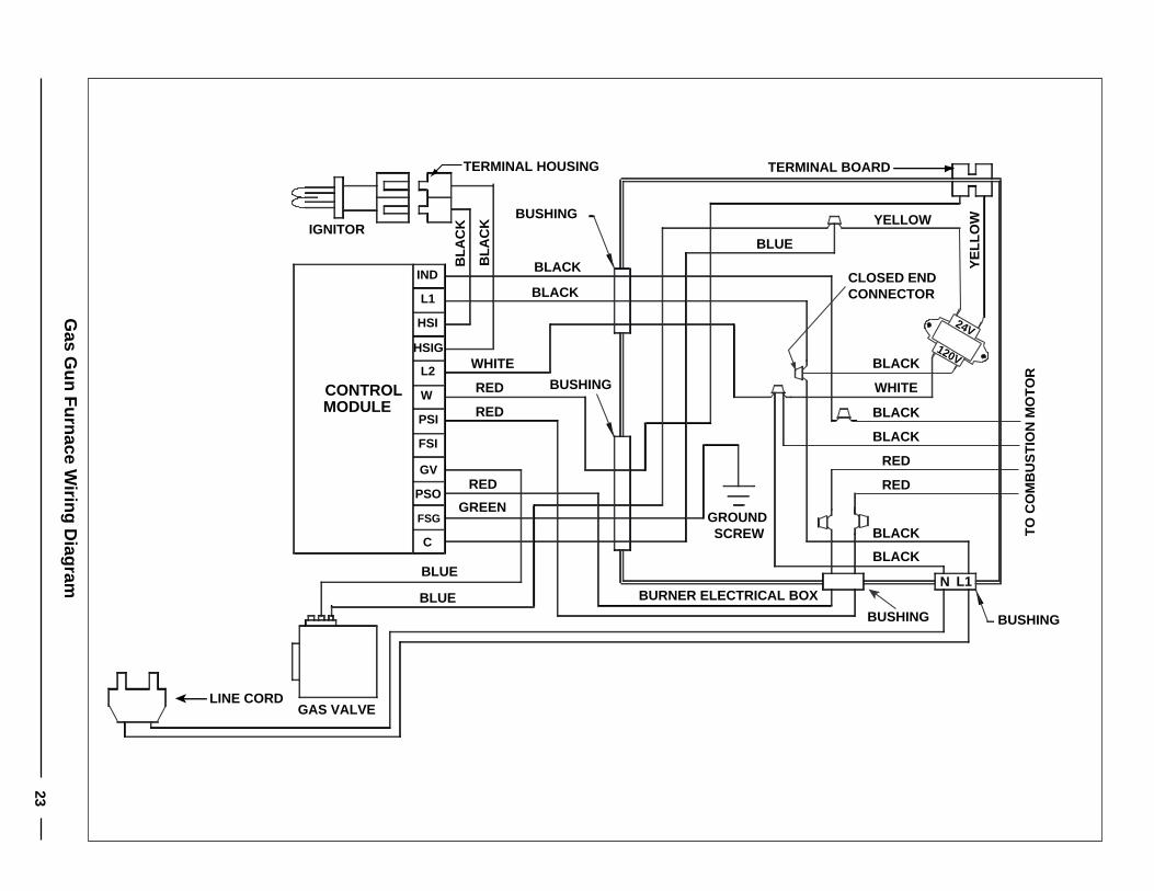
un Furnace W
iring Diagram
TERMINAL BOARD
BUSHINGBUSHING
BUSHING
BUSHING
N L1BURNER ELECTRICAL BOX
GAS VALVE
IGNITOR
LINE CORD
CLOSED END CONNECTOR
BL
AC
K
BL
AC
K
GREEN
BLUE
BLUE
BLACK
WHITE
RED
RED
RED
BLACK
GROUND SCREW
BLACK
BLACK
120V
24V
RED
RED
BLACK
BLACK
BLACK
BLUE
YE
LL
OWYELLOW
WHITE
GV
PSO
FSG
C
IND
L1
HSI
HSIG
L2
W
PSI
FSI
CONTROLMODULE
TERMINAL HOUSING
TO
CO
MB
US
TIO
N M
OT
OR
Bur
ner
Plu
g
Rec
epta
cleB
low
er S
peed
Set
ting
Sho
wn
is th
e M
ediu
m S
peed
(see
tabl
e)
Fan
& L
imit
Con
trol
Man
ual S
w.
Fan
Sw
.
If an
y of
the
orig
inal
wire
sup
plie
dw
ith th
e ap
plia
nce
is r
epla
ced,
use
105
C w
ire o
r eq
uiva
lent
.
Lim
itS
w.
Aux
.S
w.
Doo
rS
w.
Rec
pt.
Mot
or
Doo
rS
witc
h
120V
NL1 G
Aux
. Lim
it
Blk
Blk
L112
0V G
N
1 2 3 4 5 6
1 2 3 4 5 6
11 11
Blu
e
Red
Blo
wer
Mot
or
Wht
Wht
Blk
Red
Blu
e
Blk
Wht
Wht
Blk
Red
Blo
wer
Wire
Col
orB
low
erS
peed
Blu
e
Bla
ck
Low
Med
.
Hig
h
Rep
rese
nts
Con
trol
Box
Blk
Brn
Brn
Blo
wer
Mot
orC
apac
itor
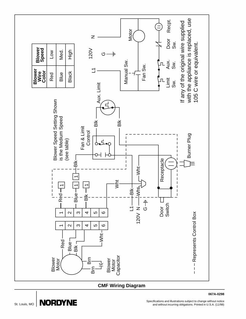
CMF Wiring Diagram
067A-0298
Specifications and illustrations subject to change without noticeand without incurring obligations. Printed in U.S.A. (11/98)St. Louis, MO