cmhc air leakage control in murbs - research report...
TRANSCRIPT
R:\5314 ‐ CMHC Air Leakage Control in MURBs\Report\CMHC Air Leakage Control in MURBs ‐ Research Report Final.docx
Development o
f Testin
g and M
easu
rement Strate
gies to
Quan
tify Air Le
akage in
MURBS
Air Le
akage Contro
l in M
ulti‐U
nit R
esid
ential B
uild
ings
CLIENT Silvio Plescia
Canada Mortgage and Housing Corporation
700 Montreal Road
Ottawa ON K1A 0P7
SUBMITTED BY RDH Building Engineering Ltd.
224 West 8th Avenue
Vancouver BC V5Y 1N5
PROJECT # 5314.00
DATE April 2, 2013
. . . . . . . . . . . . . . . . . . . . . . . . . . . . . . . . . . . . . . . . . . . . . . . . . . . . . . . . . . . . . . . . . . . . . . . . . . . . . . . . . . . . . . . . . . . . . . . . . . . . . . . . . . . . . . . . . . . . . .
5314.00 RDH Building Engineering Ltd.
Table of Contents
EXECUTIVE SUMMARY ......................................................... 1
RÉSUMÉ ................................................................................ 3
1. Project Overview ........................................................... 5
1.1. Background ........................................................ 5
1.2. Scope .................................................................. 5
2. Airflow in Multi‐Unit Residential Buildings ................... 6
2.2. Driving Forces ..................................................... 7
2.2.1 Wind ..................................................................... 7
2.2.2 Stack Effect ......................................................... 10
2.2.3 Mechanical Systems ........................................... 13
2.3. Cumulative Effect of Driving Forces ................. 15
2.4. Control of Airflow in MURBs ............................ 16
2.4.1 Exterior Enclosure Air Barrier Systems ............... 16
2.4.2 Occupant Behaviour ........................................... 28
2.4.3 Compartmentalization ........................................ 30
2.4.4 Mechanical Systems ........................................... 31
3. Airtightness Reporting and Calculations ..................... 32
3.1. Reporting Techniques ...................................... 32
3.1.1 Airflow Rate ........................................................ 33
3.1.2 Normalized Airflow Rate ..................................... 33
3.1.3 Air Change Rate .................................................. 33
3.1.4 Equivalent Leakage Area ..................................... 33
3.1.5 Effective Leakage Area ........................................ 34
3.1.6 Specific Leakage Area (Normalized
Equivalent/Effective Leakage Area) .................... 34
3.1.7 Leakage per Unit Length ..................................... 34
3.1.8 Conversions ........................................................ 34
4. Literature Review Summary........................................ 36
5. Test Procedures and Equipment ................................. 38
5.1. System Quantitative Tests................................ 38
5.1.2 CGSB 149.10 – M86 ............................................ 39
5.1.3 CGSB 149.15 – 96 ................................................ 39
5.1.4 ASTM E 779 ‐ 10 .................................................. 40
5.1.5 ASTM E 1827 ‐ 96 ................................................ 40
. . . . . . . . . . . . . . . . . . . . . . . . . . . . . . . . . . . . . . . . . . . . . . . . . . . . . . . . . . . . . . . . . . . . . . . . . . . . . . . . . . . . . . . . . . . . . . . . . . . . . . . . . . . . . . . . . . . . . .
5314.00 RDH Building Engineering Ltd.
5.1.6 ASTM E 2357 ‐ 05 ................................................ 41
5.1.7 ASTM E 741 ......................................................... 41
5.1.8 ISO 9972 .............................................................. 41
5.1.9 Pressure Neutralized Fan
Depressurization/Pressurization Technique ....... 42
5.1.10 Multi‐Zone Test Procedure ................................. 43
5.1.11 ATTMA Technical Standard L1 ‐ 2010 ................. 44
5.1.12 US Army Corps of Engineers ............................... 44
5.1.13 Other Procedures ................................................ 44
5.2. Summary of System Quantitative Testing
Procedures ....................................................... 45
5.3. Component Quantitative Tests ........................ 45
5.3.1 ASTM E 283 ‐ 04 .................................................. 45
5.3.2 ASTM E 783 ‐02 ................................................... 46
5.4. Qualitative Tests .............................................. 46
5.4.1 ASTM E 1186 – 03 ............................................... 46
5.4.2 Smoke Tracer ‐ Smoke Wand .............................. 49
5.5. Costs ................................................................. 49
5.6. Test Equipment ................................................ 50
5.6.1 High Capacity Blower Systems ............................ 50
5.6.2 Fan‐door Systems................................................ 51
5.6.3 Infrared Cameras ................................................ 52
5.6.4 Smoke Generators .............................................. 52
5.6.5 Smoke Wand ....................................................... 53
5.6.6 Tracer Gasses ...................................................... 53
5.6.7 Flow measuring devices ...................................... 54
5.6.8 Pressure Measuring Devices ............................... 54
5.7. Testing During Construction ............................ 55
6. Airtightness Regulatory Requirements and Targets ... 58
6.1. Canada ............................................................. 58
6.1.1 National Building Code for Canada (NBCC) and
National Energy Code for Buildings (NECB) ........ 58
6.1.2 Leadership in Energy and Environmental Design
(LEED) Canada 2009 ............................................ 58
6.2. United States ................................................... 58
6.2.1 ASHRAE Standards 90.1 ...................................... 58
6.2.2 ASHRAE Standard 189.1 – 2011 .......................... 59
6.2.3 ASHRAE Handbook of Fundamentals 2009 ......... 59
6.2.4 Energy Star® ........................................................ 59
6.3. International ..................................................... 59
6.3.1 International Energy Conservation Code (IECC) . 59
6.3.2 International Green Construction Code (IGCC)... 60
6.3.3 International Building Code (IBC) ....................... 60
6.3.4 International Residential Code for One‐ and Two‐
Family Dwellings (IRC) ......................................... 61
6.3.5 Passivhaus ........................................................... 61
6.4. Summary of Airtightness Requirements .......... 61
7. Existing MURB Data Summary and Analysis ............... 66
7.1. MURBs .............................................................. 66
7.2. Compartmentalization ..................................... 72
7.3. United States Army Corps of Engineers ........... 73
7.4. Airtightness Retrofits ....................................... 74
8. Industry Preparedness and Perception ....................... 76
8.1. Survey Results .................................................. 76
8.2. State of Washington and City of Seattle
Experience ........................................................ 89
8.3. UK Experience .................................................. 90
8.4. Summary of Industry Preparedness and
Perception ........................................................ 90
9. Conclusions ................................................................. 92
10. Acknowledgements..................................................... 94
11. References .................................................................. 95
12. Bibliography ................................................................ 97
13. Glossary of Terms ....................................................... 99
Appendices
Appendix A – MURB Airtightness Database
Appendix B – Industry Survey
Appendix C – Airtightness Database Data Collection Form

. . . . . . . . . . . . . . . . . . . . . . . . . . . . . . . . . . . . . . . . . . . . . . . . . . . . . . . . . . . . . . . . . . . . . . . . . . . . . . . . . . . . . . . . . . . . . . . . . . . . . . . . . . . . . . . . . . . . . .
5314.00 RDH Building Engineering Ltd.
EXECUTIVE SUMMARY
The uncontrolled flow or air in to, out of, and within multi‐unit residential buildings (MURBs) can create performance problems
with respect to energy consumption, moisture, and indoor air quality. Currently, there is no mandatory airtightness
requirement for MURBs in Canada. This study provides a review of the current state of the industry with respect to airtightness
in MURBs including testing requirements and techniques, performance targets, current MURB airtightness, and industry
airtightness testing capacity.
Airflow in MURBs is driven by pressure differences that are primarily created as a result of wind, stack effect, and building
mechanical ventilation systems. To help control the airflow as a result of these forces, air sealing is used both as part of the
exterior building enclosure and as part of interior separators. The use of air sealing in interior separators such as floor slabs and
walls is often referred to as compartmentalization.
Literature regarding airtightness testing, specifications and building case‐studies with respect to MURBs was reviewed to gain an
understanding of the current information available in industry. Based on this review it was found that airtightness testing of
MURBs is not widespread in North America; however, the specialized airtightness testing equipment that is required to perform
this type of testing is typically readily available. Additionally, while quantitative testing allows for the numerical comparison of
airtightness performance, qualitative testing can be useful for identifying air leakage locations especially as part of forensic and
quality control procedures.
Numerous test procedures and specifications exist in North America and world‐wide. These include standards by CGSB
(Canadian General Standards Board), ASTM (American Society for Testing and Material), ISO (International Organization for
Standardization). Additionally, specific programs such as LEED (Leadership in Energy and Environmental Design) have
requirements to achieve accreditation. One of the most consistently implemented testing procedures and performance
standards in North America is governed by the United States Army Corps of Engineers (USACE) which mandates that all of its
building be tested to ensure compliance with its requirement of 0.25 cfm/ft² (1.27 L/s∙m²) of enclosure area at an indoor‐to‐
outdoor pressure differential of 75 Pa. This performance target has been consistently met on hundreds of USACE buildings
including barracks buildings which are similar in form to a typical MURB.
To determine the current airtightness performance of MURBs, a database of MURB airtightness testing results was created
using data provided by project team members and well as other organizations in industry. Based on the data collected, MURBs
currently being tested have an average airtightness of approximately 0.74 cfm/ft² (3.76 L/s∙m²). This value includes all MURBs in
the database that were appropriately tested except for those tested as part of the US ACE requirement. The airtightness of
MURBs generally decreases with age which indicates that MURBs are being more designed and constructed more air‐tightly
now than they were previously. The buildings in the database were also analysed with respect to compartmentalization when
data for balanced testing and 6‐sided testing was available, and this analysis indicated that generally interior separators were
more airtight than the exterior enclosure. However, this may be because 6‐sided airtightness testing is required by LEED so
most of this type of testing is done to meet the LEED requirement which may skew the results because buildings that are built to
meet a specific performance requirement that will be verified through testing typically are more airtight than comparable
buildings without this requirement. This is evident through the USACE building data which clearly indicates the value of an
airtightness performance requirement and mandatory verification testing. In reality, it is likely that interior separators are less
airtight than the exterior enclosure.
While a broad survey of industry was conducted to gauge industry perception and preparedness with respect to airtightness
testing, respondents to the survey were more likely to be involved with airtightness of buildings than the average industry
member, implying a bias in the survey responses. The responses indicate a general support for the implementation of
airtightness testing and performance and regulatory requirement for MURBs, and many respondents felt that while industry
capacity may not currently exist, it could be developed within approximately 2 years with the aid of training programs.
. . . . . . . . . . . . . . . . . . . . . . . . . . . . . . . . . . . . . . . . . . . . . . . . . . . . . . . . . . . . . . . . . . . . . . . . . . . . . . . . . . . . . . . . . . . . . . . . . . . . . . . . . . . . . . . . . . . . . .
5314.00 RDH Building Engineering Ltd.
....
PAGE 2 OF 102
Airtightness was identified as important in MURBs for energy conservation, moisture control, indoor air quality, and acoustics,
in order of importance.
Based on the review of test standards and procedures it was determined that an initial performance target, for the whole
building, of 0.40 cfm/ft² (2.0 L/s∙m²) may provide a good value for use in Canadian codes and standards. However, testing
procedures such as those by CGSB and ASTM need to be adapted to better accommodate the compartmentalized nature of
MURBs, or a new testing standard could be created using the Pressure Neutralized Fan Depressurization/Pressurization
technique. The implementation of any airtightness testing and performance requirement would require a grace period to allow
for the development of industry capacity.
. . . . . . . . . . . . . . . . . . . . . . . . . . . . . . . . . . . . . . . . . . . . . . . . . . . . . . . . . . . . . . . . . . . . . . . . . . . . . . . . . . . . . . . . . . . . . . . . . . . . . . . . . . . . . . . . . . . . . .
5314.00 RDH Building Engineering Ltd.
....
PAGE 3 OF 102
RÉSUMÉ
La circulation incontrôlée de l’air vers l’intérieur et l’extérieur des collectifs d’habitation, ou encore à l’intérieur même de ceux‐
ci, peuvent engendrer des problèmes de performance sur le plan de la consommation d’énergie, de l’humidité et de la qualité
de l’air intérieur. Il n’existe actuellement, au Canada, aucune exigence obligatoire relative à l’étanchéité à l’air pour les collectifs
d’habitation. Dans la présente étude, on se penche sur la situation actuelle de l’industrie en matière d’étanchéité à l’air dans les
collectifs d’habitation, notamment les exigences et les techniques d’essai, les cibles de performance, l’étanchéité à l’air
courante des collectifs d’habitation et la capacité de l’industrie à réaliser des essais d’étanchéité à l’air.
La circulation d’air dans les collectifs d’habitation est causée par les différences de pression qui sont principalement créées par
le vent, l’effet de cheminée et les installations de ventilation mécanique des bâtiments. Afin d’aider à contrôler la circulation
d’air engendrée par ces forces, on a recours à l’étanchéisation à l’air tant dans l’enveloppe extérieure du bâtiment que dans les
séparateurs intérieurs. Le recours à l’étanchéisation à l’air dans les séparateurs intérieurs, comme les dalles de plancher et les
murs, est souvent appelé la compartimentation.
Les documents portant sur les essais d’étanchéité à l’air, les spécifications et les études de cas d’immeubles visant des collectifs
d’habitation ont été examinés afin de comprendre l’information dont dispose actuellement l’industrie. En se fondant sur cet
examen, on a constaté que les essais d’étanchéité à l’air des collectifs d’habitation ne sont pas pratique courante en Amérique
du Nord; cependant, l’équipement spécialisé nécessaire pour effectuer ces essais est habituellement facile à obtenir. De plus,
bien que les essais quantitatifs permettent de réaliser une comparaison numérique de la performance sur le plan de
l’étanchéité à l’air, les essais qualitatifs peuvent être utiles pour déterminer les endroits où il y a infiltration d’air,
particulièrement dans le cadre des procédures en laboratoire et de contrôle de la qualité.
Il existe de nombreuses procédures et spécifications d’essai en Amérique du Nord et à l’échelle mondiale, notamment les
normes de l’ONGC (Office des normes générales du Canada), de l’ASTM (American Society for Testing and Material) et de l’ISO
(Organisation internationale de normalisation). En outre, des programmes spécifiques, comme LEED (Leadership in Energy and
Environmental Design), établissent des exigences pour l’obtention d’une certification. L’une des procédures d’essai et normes
de performance le plus souvent utilisée en Amérique du Nord est régie par le United States Army Corps of Engineers (USACE)
qui exige que tous ses bâtiments soient mis à l’essai afin de s’assurer qu’ils ont une enveloppe offrant une performance de
0,25 pi3/min par pi2 (1,27 L/s par m²) à une pression différentielle de l’intérieur vers l’extérieur de 75 Pa. Cette cible de
performance a toujours été atteinte dans des centaines de bâtiments de l’USACE, notamment les bâtiments de casernement
dont la forme rappelle celle d’un collectif d’habitation typique.
Pour déterminer la performance actuelle des collectifs d’habitation sur le plan de l’étanchéité à l’air, on a créé une base de
données sur les essais d’étanchéité à l’air des collectifs d’habitation à partir de données fournies par les membres d’équipes de
projet ainsi que par d’autres organisations de l’industrie. En se fondant sur les données recueillies, les collectifs d’habitation qui
sont mis à l’essai actuellement ont une étanchéité à l’air d’environ 0,74 pi3/min par pi2 (3,76 L/s par m²). Cette valeur vaut pour
tous les collectifs d’habitation figurant dans la base de données qui ont été adéquatement mis à l’essai conformément à
l’exigence de l’USACE. L’étanchéité à l’air des collectifs d’habitation diminue généralement au fur et à mesure qu’ils prennent de
l’âge, ce qui signifie que les collectifs d’habitation sont maintenant conçus et construits pour être plus étanche à l’air qu’ils ne
l’étaient auparavant. La compartimentation des immeubles figurant dans la base de données a été analysée lorsque les données
sur les essais équilibrés et les essais sur six côtés ont été accessibles, et cette analyse a révélé que les séparateurs intérieurs
étaient généralement plus étanches à l’air que l’enveloppe extérieure du bâtiment. Cependant, ce résultat peut être attribuable
aux essais d’étanchéité à l’air sur six côtés qui sont exigés pour la certification LEED, ce qui pourrait fausser les résultats parce
que les immeubles construits pour être conformes à une exigence de performance précise, qui sera vérifiée à l’aide d’essais,
sont habituellement plus étanches à l’air que des immeubles comparables qui ne respectent pas cette exigence. On le constate
par les données sur les bâtiments de l’USACE qui indiquent clairement la valeur d’une exigence relative à l’étanchéité à l’air et

. . . . . . . . . . . . . . . . . . . . . . . . . . . . . . . . . . . . . . . . . . . . . . . . . . . . . . . . . . . . . . . . . . . . . . . . . . . . . . . . . . . . . . . . . . . . . . . . . . . . . . . . . . . . . . . . . . . . . .
5314.00 RDH Building Engineering Ltd.
....
PAGE 4 OF 102
des essais de vérification obligatoires. En réalité, il est probable que les séparateurs intérieurs sont moins étanches à l’air que
l’enveloppe du bâtiment.
Alors, une enquête auprès des gens de l’industrie afin de juger de leur perception et de leur état de préparation relativement
aux essais d’étanchéité à l’air les répondants à l'enquête étaient plus susceptibles d'être impliqués avec étanchéité à l'air des
bâtiments que le membre moyen de l'industrie, ce qui implique un biais dans les réponses à l'enquête. Les réponses indiquent
un appui général en faveur de la mise en œuvre des essais d’étanchéité à l’air et des exigences règlementaires relatives à la
performance des collectifs d’habitation, et bon nombre de répondants pensaient que bien que la capacité de l’industrie existe
actuellement, elle pourrait être développée d’ici deux ans en offrant des programmes de formation. L’étanchéité à l’air a été
soulignée comme étant importante dans les collectifs d’habitation sur le plan de l’économie d’énergie, du contrôle de
l’humidité, de la qualité de l’air et de l’acoustique (dans cet ordre de priorité).
En se fondant sur l’examen des normes et procédures d’essai, on a établi qu’une cible de performance initiale pour l'ensemble
du bâtiment de 0,40 pi3/min par pi2 (2,0 L/s par m²) pourrait présenter une bonne valeur pouvant être utilisée dans les codes et
normes du Canada. Toutefois, les procédures d’essai, comme celles établies par l’ONGC et l’ASTM, doivent être adaptées afin de
correspondre davantage à la nature compartimentée des collectifs d’habitation, ou l’on pourrait rédiger une nouvelle norme en
se servant de la technique de dépressurisation/pressurisation avec un ventilateur à pression neutre. Pour mettre en œuvre tout
essai d’étanchéité à l’air et une exigence de performance, il faudrait qu’il y ait un délai de grâce afin de permettre à l’industrie
de développer sa capacité.
. . . . . . . . . . . . . . . . . . . . . . . . . . . . . . . . . . . . . . . . . . . . . . . . . . . . . . . . . . . . . . . . . . . . . . . . . . . . . . . . . . . . . . . . . . . . . . . . . . . . . . . . . . . . . . . . . . . . . .
5314.00 RDH Building Engineering Ltd.
....
PAGE 5 OF 102
1. Project Overview
1.1. Background
Air leakage or inadequately controlled airflow into, out of, and within multi‐unit residential buildings (MURBs) has historically
been associated with performance issues including moisture damage as a result of interstitial condensation, comfort issues as a
result of cold drafts, and indoor air quality concerns. Recently, in response to increasing societal concerns and rising energy
costs, additional focus has been put on limiting air leakage as part of energy conservation targets. As Lovatt correctly identifies,
an “airtightness testing requirement … represents one of the first ‘as‐built’ requirements related to energy use in building
codes.” (Lovatt 2008)
Testing of air leakage characteristics in houses has been common practice in Canada for approximately 35 years with roughly
250,000 to 500,000 houses having been tested in that time. The technology associated with measurement is readily available
and many practitioners are able to undertake the testing. As a result of this wide‐scale testing, a large volume of data has been
accumulated that provides a comprehensive profile of typical airtightness levels in houses. While some air leakage testing has
been undertaken on larger buildings, due to the often more complex nature of testing procedures, lack of regulation, and the
larger scale equipment that can be required, this type of testing is significantly less frequent and is particularly rare for MURBs.
Because limited testing has been performed and the results from tests that have been performed are largely not compiled, it is
difficult to determine typical air leakage characteristics for MURBs. As there are over 3 million residential dwellings in Canadian
MURBs and combined these use more than 141 million gigajoules of energy each year, this represents a significant knowledge,
testing, and regulation gap. (Natural Resources Canada 2007)
As part of controlling air leakage into and out of MURBs it is practical to set quantitative requirements in building regulations;
however, to set these requirements, certain information is necessary: a qualitative understanding of airflow; an understanding
of the required level of airtightness for performance; an understanding of current airtightness performance and the feasibility of
achieving certain airtightness targets; and a practical and economical testing method to confirm that the airtightness targets are
met. This report seeks to further the understanding of these areas by providing an update and expansion of the previous CMHC
research report Air Leakage Characteristics, Test Methods and Specifications for Large Buildings (2001) by Proskiw and Phillips.
1.2. Scope
To develop the understanding of airtightness in MURBs, this study undertook a number of tasks. These tasks, as specified in the
project proposal, are listed below.
Literature review
Study of large building airtightness regulatory requirements in international jurisdictions and industry capacity to ensure compliance with regulations
Review of industry preparedness in Canada to address air leakage control in MURBs
To complete these tasks, a number of distinct techniques were used and these are provided below.
Review of literature relevant to MURB airtightness
Review of testing protocols and standards (Canadian and International)
Survey of industry involvement and preparedness
Compilation of a MURB airtightness database
This study deals specifically with airtightness characteristics of the exterior building enclosure of MURBs and also provides some
discussion of internal airflows, in particular with respect to compartmentalization.
. . . . . . . . . . . . . . . . . . . . . . . . . . . . . . . . . . . . . . . . . . . . . . . . . . . . . . . . . . . . . . . . . . . . . . . . . . . . . . . . . . . . . . . . . . . . . . . . . . . . . . . . . . . . . . . . . . . . . .
5314.00 RDH Building Engineering Ltd.
....
PAGE 6 OF 102
2. Airflow in Multi‐Unit Residential Buildings
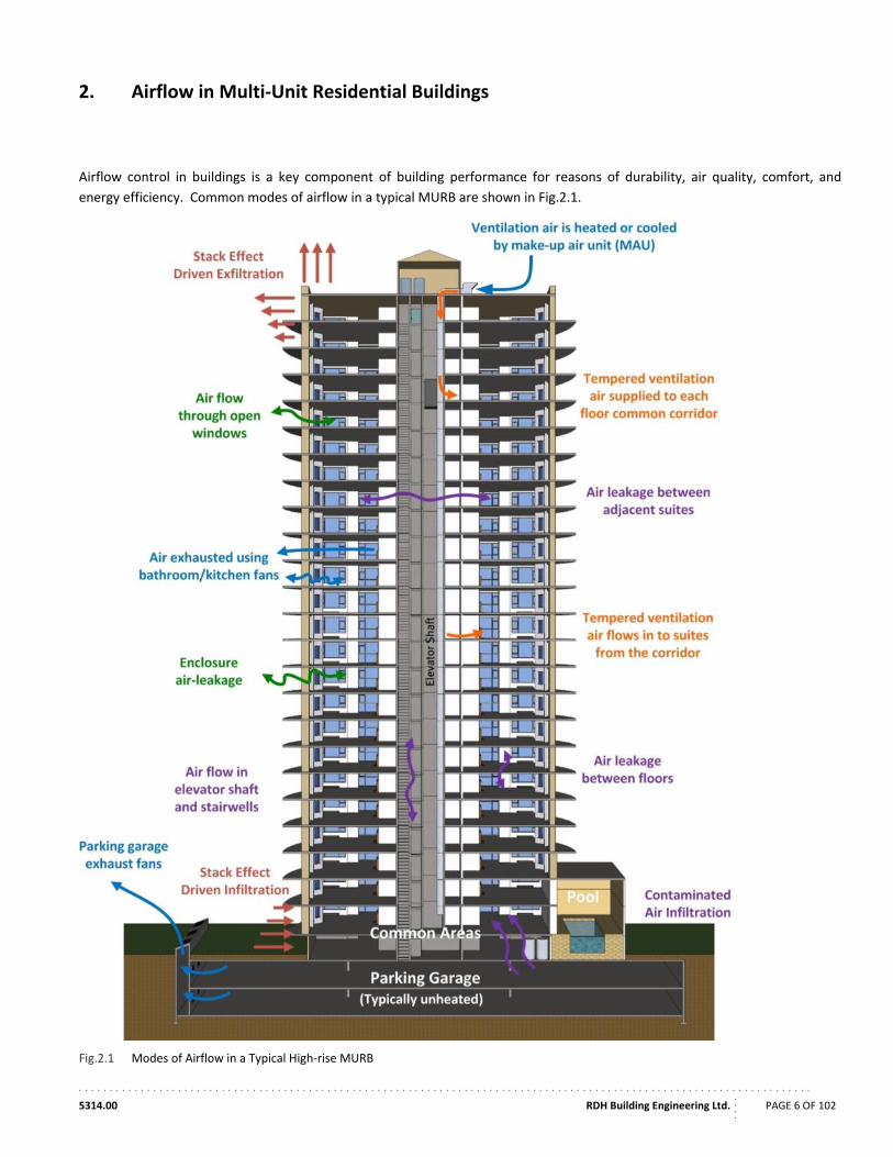
Airflow control in buildings is a key component of building performance for reasons of durability, air quality, comfort, and
energy efficiency. Common modes of airflow in a typical MURB are shown in Fig.2.1.
Fig.2.1 Modes of Airflow in a Typical High‐rise MURB
. . . . . . . . . . . . . . . . . . . . . . . . . . . . . . . . . . . . . . . . . . . . . . . . . . . . . . . . . . . . . . . . . . . . . . . . . . . . . . . . . . . . . . . . . . . . . . . . . . . . . . . . . . . . . . . . . . . . . .
5314.00 RDH Building Engineering Ltd.
....
PAGE 7 OF 102
The control of airflow can be separated into two fundamental components: driving forces and control methods. Before
effective control of airflow can be established, the driving forces behind the airflow need to be understood. These components
of airflow are discussed in the subsequent sections.
2.2. Driving Forces
Airflow between spaces (i.e. rooms, suites, storeys) in residential buildings is driven by pressure differences between these
spaces. These pressure differences can exist between the exterior and the interior, or between internal building spaces. The
pressure differences can be created by the wind, stack effect, and mechanical supply and exhaust fans. These forces are further
discussed in the following sections.
2.2.1 Wind
Wind typically creates the peak pressure differences across the building enclosure. Positive pressure differentials occur on the
windward side of the building, forcing air into the building through openings. At the same time, negative pressure differentials
on the roof and leeward sides will draw air out of the building. These pressure differences tend to cause air to flow through the
building horizontally from the windward side towards the leeward side of the building.
Wind pressures experienced by a building depend generally on the climate in which the building is located and the exposure of
the building to wind which can be impacted by the shape, height, and orientation of the building as well as local geography, and
sheltering provided by neighbouring objects.
Wind pressures up to 50 Pa for exposed buildings located in Canada are common and can range much higher for short periods.
Average pressures in the range of 5 Pa to 10 Pa are common; however, this depends on the exposure of the building,
microclimate, and building geometry including height above grade.
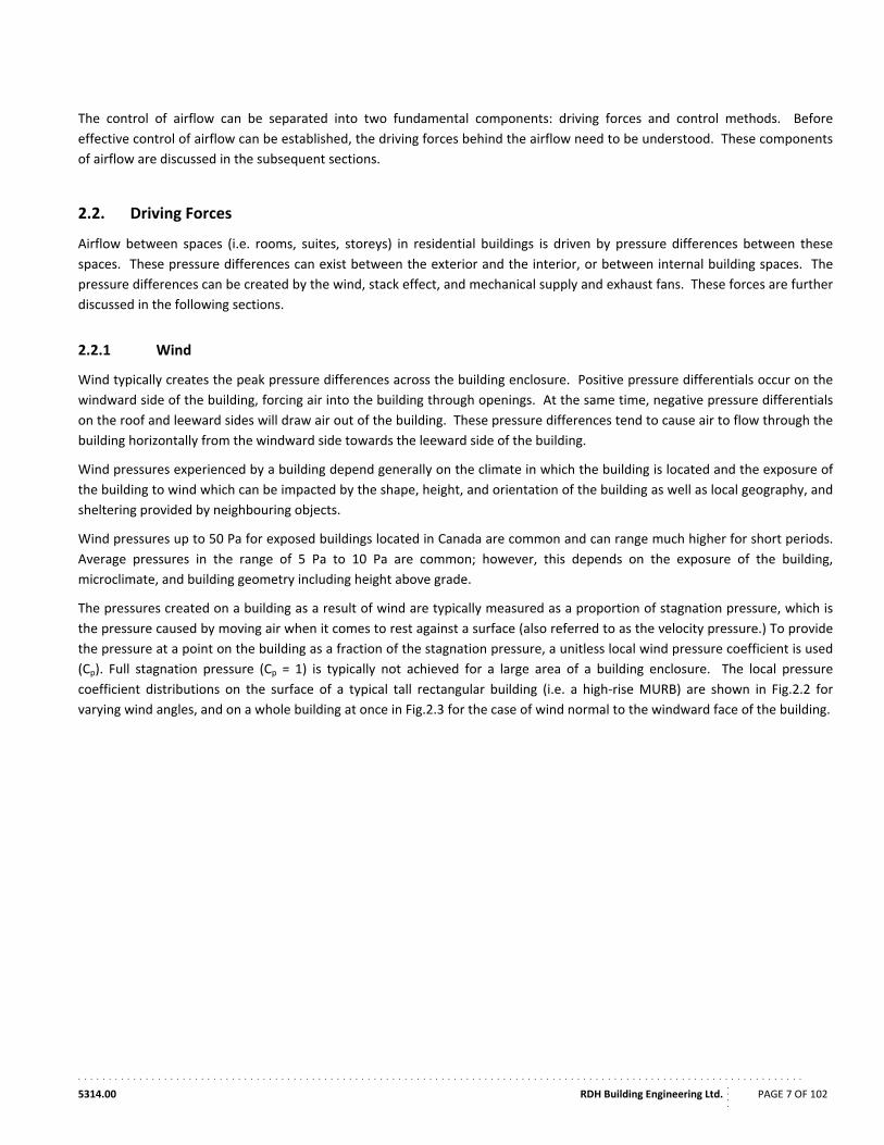
The pressures created on a building as a result of wind are typically measured as a proportion of stagnation pressure, which is
the pressure caused by moving air when it comes to rest against a surface (also referred to as the velocity pressure.) To provide
the pressure at a point on the building as a fraction of the stagnation pressure, a unitless local wind pressure coefficient is used
(Cp). Full stagnation pressure (Cp = 1) is typically not achieved for a large area of a building enclosure. The local pressure
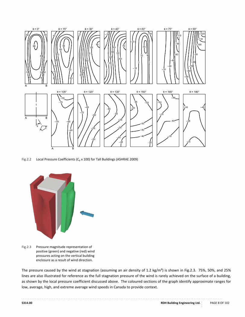
coefficient distributions on the surface of a typical tall rectangular building (i.e. a high‐rise MURB) are shown in Fig.2.2 for
varying wind angles, and on a whole building at once in Fig.2.3 for the case of wind normal to the windward face of the building.
. . . . . . . . . . . . . . . . . . . . . . . . . . . . . . . . . . . . . . . . . . . . . . . . . . . . . . . . . . . . . . . . . . . . . . . . . . . . . . . . . . . . . . . . . . . . . . . . . . . . . . . . . . . . . . . . . . . . . .
5314.00 RDH Building Engineering Ltd.
....
PAGE 8 OF 102
Fig.2.2 Local Pressure Coefficients (Cp x 100) for Tall Buildings (ASHRAE 2009)
Fig.2.3 Pressure magnitude representation of positive (green) and negative (red) wind pressures acting on the vertical building enclosure as a result of wind direction.
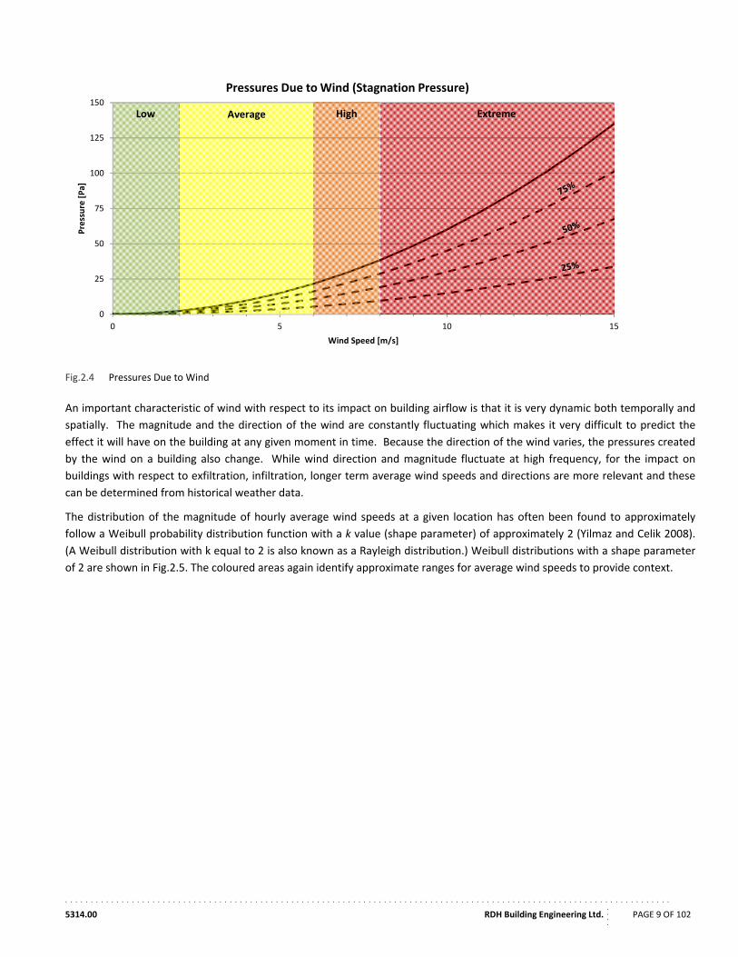
The pressure caused by the wind at stagnation (assuming an air density of 1.2 kg/m³) is shown in Fig.2.3. 75%, 50%, and 25%
lines are also illustrated for reference as the full stagnation pressure of the wind is rarely achieved on the surface of a building,
as shown by the local pressure coefficient discussed above. The coloured sections of the graph identify approximate ranges for
low, average, high, and extreme average wind speeds in Canada to provide context.
. . . . . . . . . . . . . . . . . . . . . . . . . . . . . . . . . . . . . . . . . . . . . . . . . . . . . . . . . . . . . . . . . . . . . . . . . . . . . . . . . . . . . . . . . . . . . . . . . . . . . . . . . . . . . . . . . . . . . .
5314.00 RDH Building Engineering Ltd.
....
PAGE 9 OF 102
Fig.2.4 Pressures Due to Wind
An important characteristic of wind with respect to its impact on building airflow is that it is very dynamic both temporally and
spatially. The magnitude and the direction of the wind are constantly fluctuating which makes it very difficult to predict the
effect it will have on the building at any given moment in time. Because the direction of the wind varies, the pressures created
by the wind on a building also change. While wind direction and magnitude fluctuate at high frequency, for the impact on
buildings with respect to exfiltration, infiltration, longer term average wind speeds and directions are more relevant and these
can be determined from historical weather data.
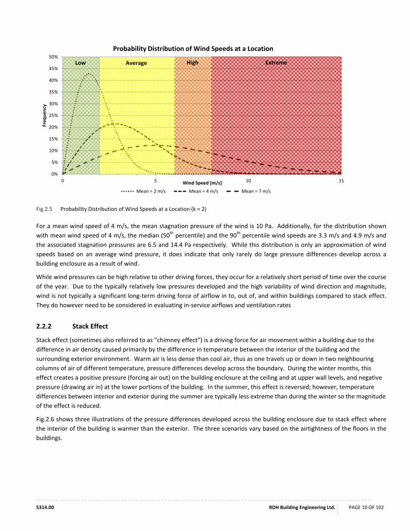
The distribution of the magnitude of hourly average wind speeds at a given location has often been found to approximately
follow a Weibull probability distribution function with a k value (shape parameter) of approximately 2 (Yilmaz and Celik 2008).
(A Weibull distribution with k equal to 2 is also known as a Rayleigh distribution.) Weibull distributions with a shape parameter
of 2 are shown in Fig.2.5. The coloured areas again identify approximate ranges for average wind speeds to provide context.
0
25
50
75
100
125
150
0 5 10 15
Pressure [Pa]
Wind Speed [m/s]
Pressures Due to Wind (Stagnation Pressure)
Low Average High Extreme
. . . . . . . . . . . . . . . . . . . . . . . . . . . . . . . . . . . . . . . . . . . . . . . . . . . . . . . . . . . . . . . . . . . . . . . . . . . . . . . . . . . . . . . . . . . . . . . . . . . . . . . . . . . . . . . . . . . . . .
5314.00 RDH Building Engineering Ltd.
....
PAGE 10 OF 102
Fig.2.5 Probability Distribution of Wind Speeds at a Location (k = 2)
For a mean wind speed of 4 m/s, the mean stagnation pressure of the wind is 10 Pa. Additionally, for the distribution shown
with mean wind speed of 4 m/s, the median (50th percentile) and the 90th percentile wind speeds are 3.3 m/s and 4.9 m/s and
the associated stagnation pressures are 6.5 and 14.4 Pa respectively. While this distribution is only an approximation of wind
speeds based on an average wind pressure, it does indicate that only rarely do large pressure differences develop across a
building enclosure as a result of wind.
While wind pressures can be high relative to other driving forces, they occur for a relatively short period of time over the course
of the year. Due to the typically relatively low pressures developed and the high variability of wind direction and magnitude,
wind is not typically a significant long‐term driving force of airflow in to, out of, and within buildings compared to stack effect.
They do however need to be considered in evaluating in‐service airflows and ventilation rates
2.2.2 Stack Effect
Stack effect (sometimes also referred to as “chimney effect”) is a driving force for air movement within a building due to the
difference in air density caused primarily by the difference in temperature between the interior of the building and the
surrounding exterior environment. Warm air is less dense than cool air, thus as one travels up or down in two neighbouring
columns of air of different temperature, pressure differences develop across the boundary. During the winter months, this
effect creates a positive pressure (forcing air out) on the building enclosure at the ceiling and at upper wall levels, and negative
pressure (drawing air in) at the lower portions of the building. In the summer, this effect is reversed; however, temperature
differences between interior and exterior during the summer are typically less extreme than during the winter so the magnitude
of the effect is reduced.
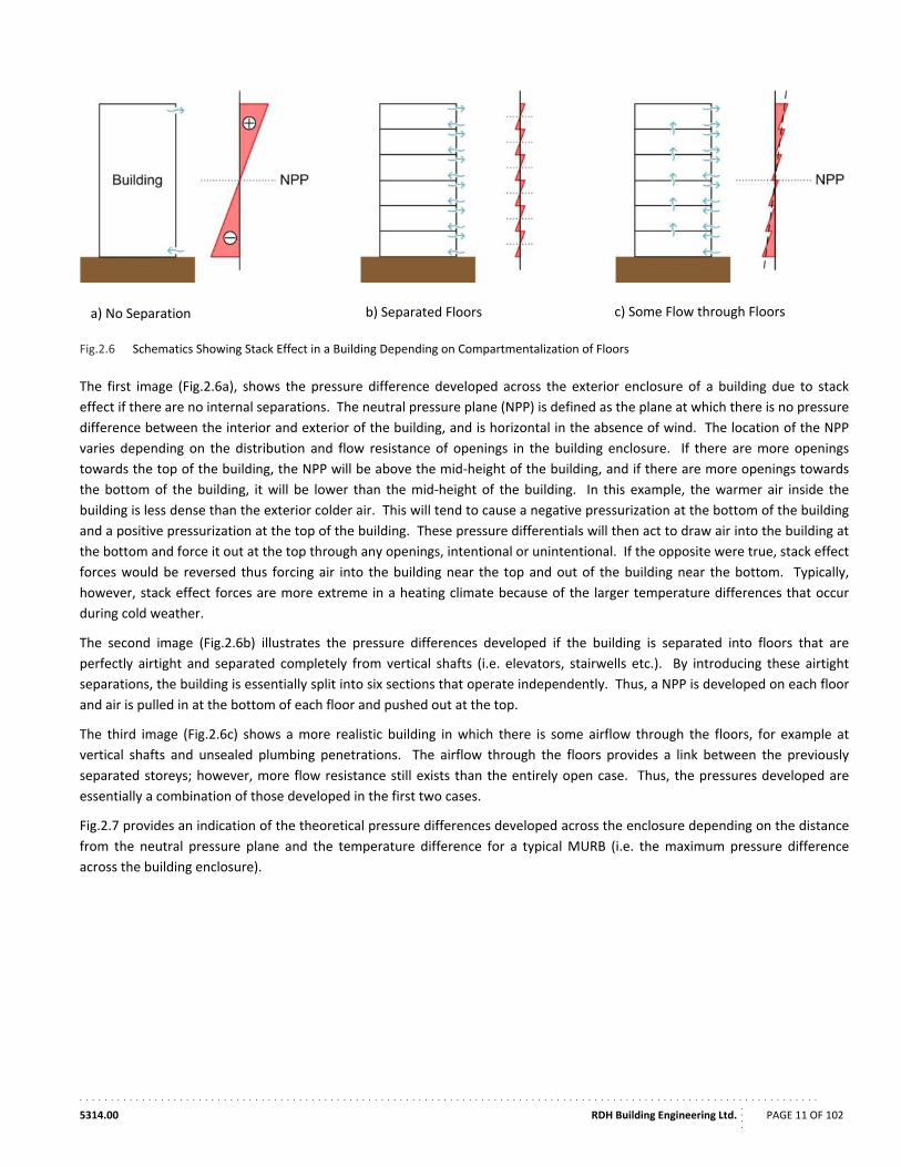
Fig.2.6 shows three illustrations of the pressure differences developed across the building enclosure due to stack effect where
the interior of the building is warmer than the exterior. The three scenarios vary based on the airtightness of the floors in the
buildings.
0%
5%
10%
15%
20%
25%
30%
35%
40%
45%
50%
0 5 10 15
Frequency
Wind Speed [m/s]
Probability Distribution of Wind Speeds at a Location
Mean = 2 m/s Mean = 4 m/s Mean = 7 m/s
Low Average High Extreme
. . . . . . . . . . . . . . . . . . . . . . . . . . . . . . . . . . . . . . . . . . . . . . . . . . . . . . . . . . . . . . . . . . . . . . . . . . . . . . . . . . . . . . . . . . . . . . . . . . . . . . . . . . . . . . . . . . . . . .
5314.00 RDH Building Engineering Ltd.
....
PAGE 11 OF 102
Fig.2.6 Schematics Showing Stack Effect in a Building Depending on Compartmentalization of Floors
The first image (Fig.2.6a), shows the pressure difference developed across the exterior enclosure of a building due to stack
effect if there are no internal separations. The neutral pressure plane (NPP) is defined as the plane at which there is no pressure
difference between the interior and exterior of the building, and is horizontal in the absence of wind. The location of the NPP
varies depending on the distribution and flow resistance of openings in the building enclosure. If there are more openings
towards the top of the building, the NPP will be above the mid‐height of the building, and if there are more openings towards
the bottom of the building, it will be lower than the mid‐height of the building. In this example, the warmer air inside the
building is less dense than the exterior colder air. This will tend to cause a negative pressurization at the bottom of the building
and a positive pressurization at the top of the building. These pressure differentials will then act to draw air into the building at
the bottom and force it out at the top through any openings, intentional or unintentional. If the opposite were true, stack effect
forces would be reversed thus forcing air into the building near the top and out of the building near the bottom. Typically,
however, stack effect forces are more extreme in a heating climate because of the larger temperature differences that occur
during cold weather.
The second image (Fig.2.6b) illustrates the pressure differences developed if the building is separated into floors that are
perfectly airtight and separated completely from vertical shafts (i.e. elevators, stairwells etc.). By introducing these airtight
separations, the building is essentially split into six sections that operate independently. Thus, a NPP is developed on each floor
and air is pulled in at the bottom of each floor and pushed out at the top.
The third image (Fig.2.6c) shows a more realistic building in which there is some airflow through the floors, for example at
vertical shafts and unsealed plumbing penetrations. The airflow through the floors provides a link between the previously
separated storeys; however, more flow resistance still exists than the entirely open case. Thus, the pressures developed are
essentially a combination of those developed in the first two cases.
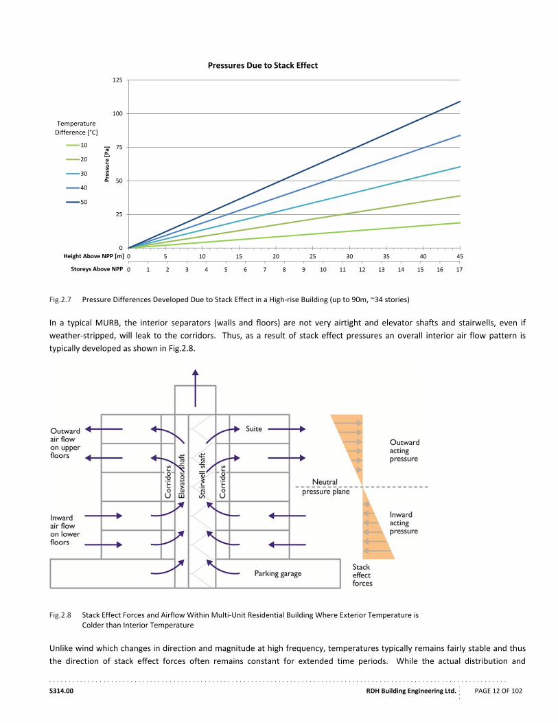
Fig.2.7 provides an indication of the theoretical pressure differences developed across the enclosure depending on the distance
from the neutral pressure plane and the temperature difference for a typical MURB (i.e. the maximum pressure difference
across the building enclosure).
a) No Separation b) Separated Floors c) Some Flow through Floors
. . . . . . . . . . . . . . . . . . . . . . . . . . . . . . . . . . . . . . . . . . . . . . . . . . . . . . . . . . . . . . . . . . . . . . . . . . . . . . . . . . . . . . . . . . . . . . . . . . . . . . . . . . . . . . . . . . . . . .
5314.00 RDH Building Engineering Ltd.
....
PAGE 12 OF 102
Fig.2.7 Pressure Differences Developed Due to Stack Effect in a High‐rise Building (up to 90m, ~34 stories)
In a typical MURB, the interior separators (walls and floors) are not very airtight and elevator shafts and stairwells, even if
weather‐stripped, will leak to the corridors. Thus, as a result of stack effect pressures an overall interior air flow pattern is
typically developed as shown in Fig.2.8.
Fig.2.8 Stack Effect Forces and Airflow Within Multi‐Unit Residential Building Where Exterior Temperature is Colder than Interior Temperature
Unlike wind which changes in direction and magnitude at high frequency, temperatures typically remains fairly stable and thus
the direction of stack effect forces often remains constant for extended time periods. While the actual distribution and
0 1 2 3 4 5 6 7 8 9 10 11 12 13 14 15 16 17
0
25
50
75
100
125
0 5 10 15 20 25 30 35 40 45
Storeys Above NPP
Pressure [Pa]
Height Above NPP [m]
Pressures Due to Stack Effect
10
20
30
40
50
TemperatureDifference [°C]
. . . . . . . . . . . . . . . . . . . . . . . . . . . . . . . . . . . . . . . . . . . . . . . . . . . . . . . . . . . . . . . . . . . . . . . . . . . . . . . . . . . . . . . . . . . . . . . . . . . . . . . . . . . . . . . . . . . . . .
5314.00 RDH Building Engineering Ltd.
....
PAGE 13 OF 102
magnitude of the pressure differences developed due to stack effect in a real building will depend on the flow resistance and
distribution of openings through both the building enclosure and interior separators such as floor slabs, and between vertical
shafts and floors, the pressures created due to stack effect is a consistent driving force that is a significant factor in long‐term
airflow patterns for a building.
2.2.3 Mechanical Systems
Buildings typically have mechanical ventilation systems to ensure the provision of adequate fresh air for the maintenance of
indoor air quality and occupant health. These systems frequently develop pressure differences across the building enclosure
and interior separators when they draw air out of or force air into building spaces. In fact, some systems rely on the
development of these pressure differences for the proper operation of the ventilation system. The pressure differences that are
developed by the mechanical systems, whether intentional or unintentional, cause airflow within a building.
The magnitude of mechanical pressure differences vary widely based on building type, mechanical system, occupancy, and
several other factors. Intentional pressure differences created between spaces by mechanical systems are usually in the order
of 5 to 10 Pa in MURBs; however, much larger pressure differences can be developed in tight buildings or suites with powerful
exhaust or supply fans. For example, operating a high capacity range hood in a relatively small and airtight space could
significantly depressurize the space.
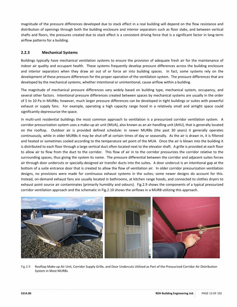
In multi‐unit residential buildings the most common approach to ventilation is a pressurized corridor ventilation system. A
corridor pressurization system uses a make‐up air unit (MUA), also known as an air‐handling unit (AHU), that is generally located
on the rooftop. Outdoor air is provided defined schedule: in newer MURBs (the past 30 years) it generally operates
continuously, while in older MURBs it may be shut‐off at certain times of day or seasonally. As the air is drawn in, it is filtered
and heated or sometimes cooled according to the temperature set point of the MUA. Once the air is blown into the building it
is distributed to each floor through a large vertical duct often located next to the elevator shaft. A grille is provided at each floor
to allow air to flow from the duct to the corridor. This flow of air in to the corridor pressurizes the corridor relative to the
surrounding spaces, thus giving the system its name. The pressure differential between the corridor and adjacent suites forces
air through door undercuts or specially‐designed air transfer ducts into the suites. A door undercut is an intentional gap at the
bottom of a suite entrance door that is created to allow the flow of ventilation air. In older corridor pressurization ventilation
designs, no provisions were made for continuous exhaust systems in the suites; some newer designs do account for this.
Instead, on‐demand exhaust fans are usually located in bathrooms, at kitchen range hoods, and connected to clothes dryers to
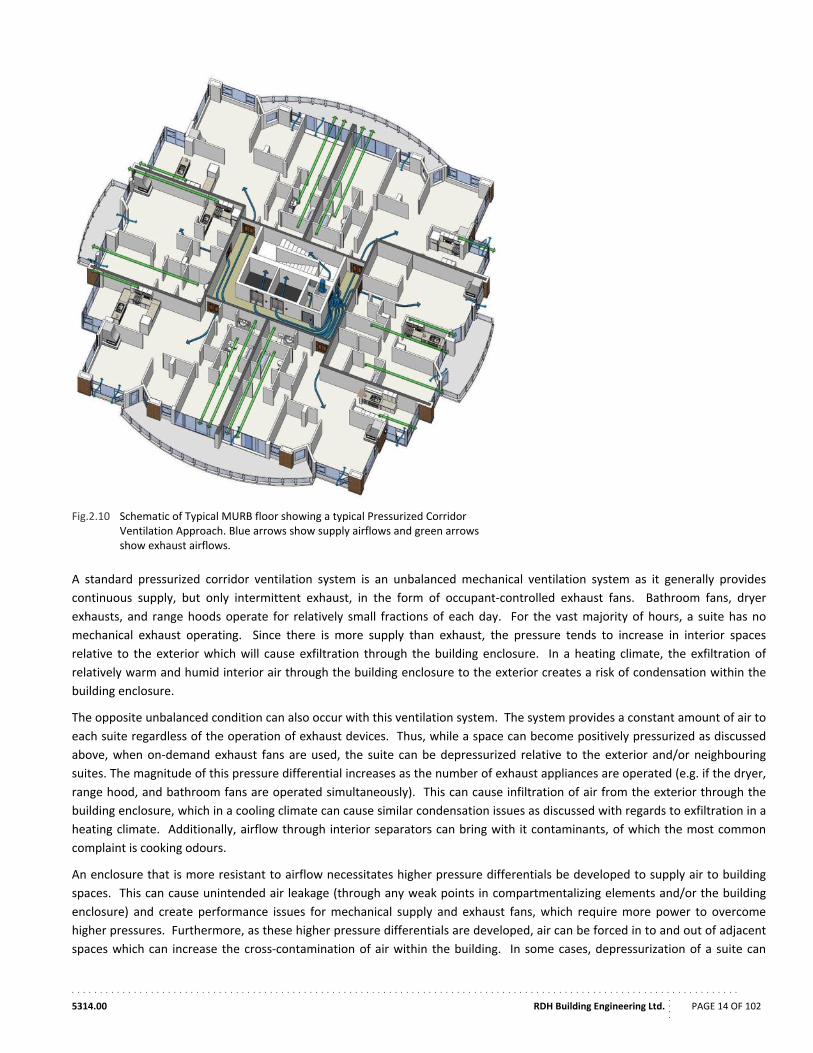
exhaust point source air contaminates (primarily humidity and odours). Fig.2.9 shows the components of a typical pressurized
corridor ventilation approach and the schematic in Fig.2.10 shows the airflows in a MURB utilizing this approach.
Fig.2.9 Rooftop Make‐up Air Unit, Corridor Supply Grille, and Door Undercuts Utilized as Part of the Pressurized Corridor Air Distribution System in Most MURBs
. . . . . . . . . . . . . . . . . . . . . . . . . . . . . . . . . . . . . . . . . . . . . . . . . . . . . . . . . . . . . . . . . . . . . . . . . . . . . . . . . . . . . . . . . . . . . . . . . . . . . . . . . . . . . . . . . . . . . .
5314.00 RDH Building Engineering Ltd.
....
PAGE 14 OF 102
Fig.2.10 Schematic of Typical MURB floor showing a typical Pressurized Corridor Ventilation Approach. Blue arrows show supply airflows and green arrows show exhaust airflows.
A standard pressurized corridor ventilation system is an unbalanced mechanical ventilation system as it generally provides
continuous supply, but only intermittent exhaust, in the form of occupant‐controlled exhaust fans. Bathroom fans, dryer
exhausts, and range hoods operate for relatively small fractions of each day. For the vast majority of hours, a suite has no
mechanical exhaust operating. Since there is more supply than exhaust, the pressure tends to increase in interior spaces
relative to the exterior which will cause exfiltration through the building enclosure. In a heating climate, the exfiltration of
relatively warm and humid interior air through the building enclosure to the exterior creates a risk of condensation within the
building enclosure.
The opposite unbalanced condition can also occur with this ventilation system. The system provides a constant amount of air to
each suite regardless of the operation of exhaust devices. Thus, while a space can become positively pressurized as discussed
above, when on‐demand exhaust fans are used, the suite can be depressurized relative to the exterior and/or neighbouring
suites. The magnitude of this pressure differential increases as the number of exhaust appliances are operated (e.g. if the dryer,
range hood, and bathroom fans are operated simultaneously). This can cause infiltration of air from the exterior through the
building enclosure, which in a cooling climate can cause similar condensation issues as discussed with regards to exfiltration in a
heating climate. Additionally, airflow through interior separators can bring with it contaminants, of which the most common
complaint is cooking odours.
An enclosure that is more resistant to airflow necessitates higher pressure differentials be developed to supply air to building
spaces. This can cause unintended air leakage (through any weak points in compartmentalizing elements and/or the building
enclosure) and create performance issues for mechanical supply and exhaust fans, which require more power to overcome
higher pressures. Furthermore, as these higher pressure differentials are developed, air can be forced in to and out of adjacent
spaces which can increase the cross‐contamination of air within the building. In some cases, depressurization of a suite can
. . . . . . . . . . . . . . . . . . . . . . . . . . . . . . . . . . . . . . . . . . . . . . . . . . . . . . . . . . . . . . . . . . . . . . . . . . . . . . . . . . . . . . . . . . . . . . . . . . . . . . . . . . . . . . . . . . . . . .
5314.00 RDH Building Engineering Ltd.
....
PAGE 15 OF 102
cause dangerous back‐drafting of combustion appliances, such as fireplace or in‐suite domestic hot water tanks, which get their
make‐up air from the suite.
As the pressurized corridor system is an unbalanced system that operates based on a pressure difference between the corridor
and the suites, if a suite entrance door is opened this will significantly alter the flow path resistance, and consequently the flow
pattern for that floor. Similarly, opening windows and operating fans can change flow paths and thus change both ventilation
rates and potentially the air source both within suites and for the rest of the building.
Gas fireplaces, whether decorative in function or for space‐heating, also affect pressures differentials across the building
enclosure and air leakage in MURBs. Atmospheric combustion fireplace units use indoor air for combustion resulting in
significant air‐exchanges while operating. The open chimney is also a source of air leakage throughout the year. Sealed
combustion fireplace units use dedicated outdoor air for combustion; however, the fireplace inserts, duct work, and dampers
are a source of potential air leakage.
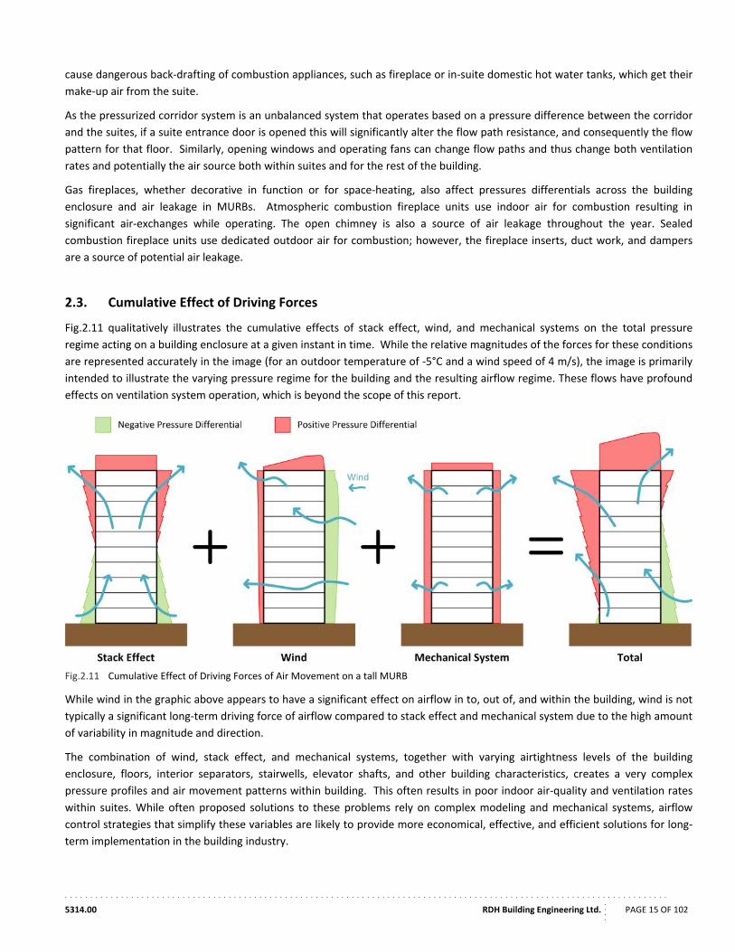
2.3. Cumulative Effect of Driving Forces
Fig.2.11 qualitatively illustrates the cumulative effects of stack effect, wind, and mechanical systems on the total pressure
regime acting on a building enclosure at a given instant in time. While the relative magnitudes of the forces for these conditions
are represented accurately in the image (for an outdoor temperature of ‐5°C and a wind speed of 4 m/s), the image is primarily
intended to illustrate the varying pressure regime for the building and the resulting airflow regime. These flows have profound
effects on ventilation system operation, which is beyond the scope of this report.
Fig.2.11 Cumulative Effect of Driving Forces of Air Movement on a tall MURB
While wind in the graphic above appears to have a significant effect on airflow in to, out of, and within the building, wind is not
typically a significant long‐term driving force of airflow compared to stack effect and mechanical system due to the high amount
of variability in magnitude and direction.
The combination of wind, stack effect, and mechanical systems, together with varying airtightness levels of the building
enclosure, floors, interior separators, stairwells, elevator shafts, and other building characteristics, creates a very complex
pressure profiles and air movement patterns within building. This often results in poor indoor air‐quality and ventilation rates
within suites. While often proposed solutions to these problems rely on complex modeling and mechanical systems, airflow
control strategies that simplify these variables are likely to provide more economical, effective, and efficient solutions for long‐
term implementation in the building industry.
. . . . . . . . . . . . . . . . . . . . . . . . . . . . . . . . . . . . . . . . . . . . . . . . . . . . . . . . . . . . . . . . . . . . . . . . . . . . . . . . . . . . . . . . . . . . . . . . . . . . . . . . . . . . . . . . . . . . . .
5314.00 RDH Building Engineering Ltd.
....
PAGE 16 OF 102
2.4. Control of Airflow in MURBs
The quantity of airflow that can occur depends on the magnitude of the driving force (the pressure difference) and on the
resistance to airflow (permeability) of the separator. Thus, to control airflow one can control either the pressure difference or
the air permeability of the separator. Building enclosure air barriers and interior compartmentalization control the permeability
of the separator to control airflow, while mechanical systems control the pressure difference.
2.4.1 Exterior Enclosure Air Barrier Systems
While mechanical systems and localised sheltering can be used to dampen the pressures experienced by the building enclosure,
the primary control of air flow in MURBs is provided by the exterior enclosure air barrier. The air barrier system must comply
with a number of design requirements in order to function adequately and remain airtight over the life of the building enclosure
assembly. The following considerations have a direct impact on MURB airtightness.
All the elements (materials) of the air barrier system must be adequately air‐impermeable.
The air barrier system must be continuous throughout the building enclosure. It must span across dissimilar materials and joints, and be sealed around penetrations such as ducts, pipes, and light fixtures.
The air barrier system must be structurally adequate or be supported to resist air pressure forces caused by peak wind loads, sustained stack effect, or fans. It must transfer any structural loads as a result of air pressure (primarily wind) to the building structure. Furthermore, the air barrier system must be sufficiently rigid or be supported so that displacement under pressure does not compromise its performance or that of other elements of the assembly.
The air barrier system should have a service life as long as that of the wall and roof assembly components or alternately should be easily accessible for repair or replacement.
An air barrier system is often provided by a combination of materials; however, there are usually one or two materials that play
a dominant role within any particular air barrier strategy. For example, sheet polyethylene and butyl sealant are the dominant
materials in a sealed polyethylene approach. General air barrier strategies for MURBs are discussed in this section; however, it
is typically the continuity of the air barrier at interfaces and penetrations that is most critical to air barrier performance and
these locations are the primary locations where building enclosure leak air. Regardless of which system or combination of
systems is used, it is critically important to overall airtightness that continuity is maintained at all parts of the building enclosure
including above grade walls, roofs, below grade walls, floor slabs, interfaces, transitions, fenestrations, and penetrations.
Air barrier systems for roofs rely on either the roofing membrane as the air barrier membrane, or supplemental air barrier
membranes and/or monolithic materials to be airtight. Roof air barrier strategies share common attributes with wall strategies;
however the number of potential air barrier strategies is limited. Critical roof air barrier details occur at roof to wall interfaces,
parapets, penetrations, and expansion joints. Manufactured fenestration components including windows, window wall, curtain
wall, doors and skylights are relatively airtight by use of frame joints/gaskets and sealants. The airtightness of fenestration
products is regulated by building and energy codes and typically products are tested to meet the requirements outlined within
referenced CSA A440, NFRC, or ASTM standards. These standards are further covered in Section 5 of this report.
Some of the strategies discussed may not be suitable for increased exposure conditions in some low‐rise MURBs and in taller
MURBs. For example, an air barrier system may not be adequately supported to resist the higher wind pressures common for
taller buildings. It is important to note that membranes, gaskets, and sealants, used at transitions in the air barrier or
penetrations, must also remain intact when wind pressures are applied to them. As an example, efforts to achieve a satisfactory
barrier to air movement in low‐rise residential construction in the early 1980s focused on the use of polyethylene sheet in
Canada and the Northern US. The poly was structurally supported by the frame, insulation and interior sheathing, and also
functioned as a primary vapour retarder material within the assembly. This approach is still commonly employed in low rise
wood‐frame MURBs though is not suitable for taller or more exposed MURBs where building pressure differentials are higher.
. . . . . . . . . . . . . . . . . . . . . . . . . . . . . . . . . . . . . . . . . . . . . . . . . . . . . . . . . . . . . . . . . . . . . . . . . . . . . . . . . . . . . . . . . . . . . . . . . . . . . . . . . . . . . . . . . . . . . .
5314.00 RDH Building Engineering Ltd.
....
PAGE 17 OF 102
As a result, in taller MURBs it is common to use alternate approaches to seal rigid sheet materials used in construction by
sealing the joints between them with gaskets or sealant, or cover with monolithic adhered or restrained sheathing membranes.
Prescriptive and general requirements for air barriers within MURBs are included within Canadian and US Building Codes,
Energy Codes and Energy Standards. In Canada, air barrier performance criteria are generally specified for enclosure materials
and components rather than for the entire building. This is primarily because it can be difficult and costly to determine entire
building air leakage rates. Also, moisture related damage as a result of air leakage is typically due to excessive air leakage at
specific components or joints rather than the entire building. However, in efforts to improve energy efficiency in the US, whole
building airtightness testing is now required within the 2012 IECC for small and large buildings. Whole building airtightness
targets of 3 to 5 ACH at 50 Pa for houses and small MURBs and less than 0.40 cfm/ft2 (2.0 L/s∙m²) of enclosure area at 75 Pa for
larger MURBs are required in states adopting the 2012 IECC. (Further discussion of the different metrics used to describe
airtightness is provided in Section 3.) These and other regulatory requirements across North America and in other global
locations are covered further in Section 5.7.
The following common air barrier strategies for walls in low‐rise to high‐rise MURB construction in North America are discussed
in the following sections.
Sealed Polyethylene Approach
Airtight Drywall Approach (ADA)
Exterior Approaches
Sealed Sheathing Approach
Sealed Sheathing Membrane Approach
o Unsupported Sheet Membranes
o Supported Sheet Membranes with vertical strapping
o Sandwiched Membranes behind exterior insulation
o Self‐Adhered and Liquid Membranes
Sprayfoam
Monolithic Material (Cast‐in‐place Concrete)
Window Wall and Curtain Wall
Other
Sealed Polyethylene Approach
The polyethylene sheet (typically, a minimum thickness of 6mm) is sealed at the top and bottom plates (wood or steel stud) to
form the wall air barrier. All joints in the polyethylene are sealed and clamped between the framing and gypsum board. The
wind load is transferred to the gypsum board in the inward direction and the framing in the outward direction. The polyethylene
must be supported by both the outboard insulation and the drywall on the interior. Locations where interior finishes are not
normally provided, such as at drop ceiling spaces and below the rim of bathtubs, require specific measures, such as the
installation of sheathing, to ensure support of the polyethylene.
In wood‐frame construction, the continuity of the air barrier at the floor header is maintained by sealing the polyethylene to the
wood framing and by sealing layers of wood framing together with sealant or gaskets, by carrying a vapour permeable
membrane to the outside of the header, or through the use of foam in the floor joist space. In non‐combustible construction,
transitions are made through floor slabs by sealing the polyethylene to the floor and ceiling.
Special attention must be paid to sealing penetrations of the gypsum board at electrical fixtures or other services. Flanged
electrical boxes and other proprietary products have been adapted for these purposes. It is also necessary to ensure continuity
of the air barrier at intersections with partition walls (at exterior wall and ceiling).
. . . . . . . . . . . . . . . . . . . . . . . . . . . . . . . . . . . . . . . . . . . . . . . . . . . . . . . . . . . . . . . . . . . . . . . . . . . . . . . . . . . . . . . . . . . . . . . . . . . . . . . . . . . . . . . . . . . . . .
5314.00 RDH Building Engineering Ltd.
....
PAGE 18 OF 102
Non‐curing sealants are appropriate for placement between sheets of polyethylene where drying of the sealant is not possible.
However, other types of sealants and gaskets are required when sealing polyethylene to wood framing or between layers of
wood.
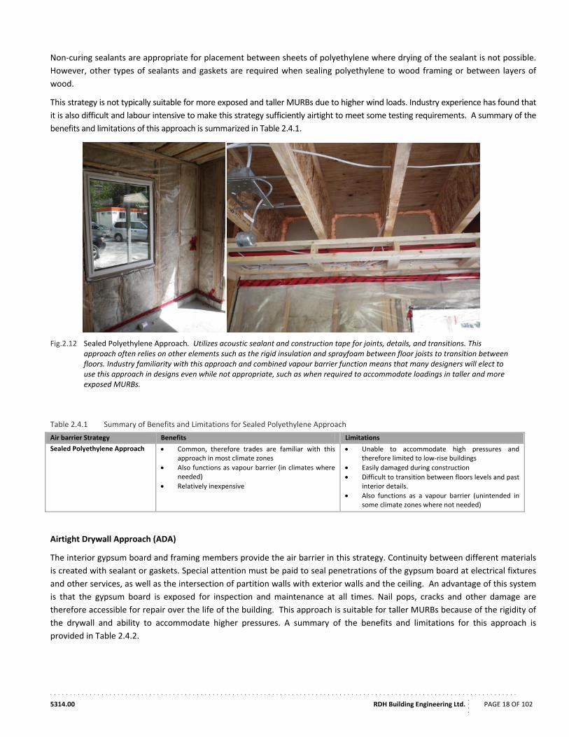
This strategy is not typically suitable for more exposed and taller MURBs due to higher wind loads. Industry experience has found that
it is also difficult and labour intensive to make this strategy sufficiently airtight to meet some testing requirements. A summary of the
benefits and limitations of this approach is summarized in Table 2.4.1.
Fig.2.12 Sealed Polyethylene Approach. Utilizes acoustic sealant and construction tape for joints, details, and transitions. This approach often relies on other elements such as the rigid insulation and sprayfoam between floor joists to transition between floors. Industry familiarity with this approach and combined vapour barrier function means that many designers will elect to use this approach in designs even while not appropriate, such as when required to accommodate loadings in taller and more exposed MURBs.
Table 2.4.1 Summary of Benefits and Limitations for Sealed Polyethylene Approach
Air barrier Strategy Benefits Limitations
Sealed Polyethylene Approach Common, therefore trades are familiar with this approach in most climate zones
Also functions as vapour barrier (in climates where needed)
Relatively inexpensive
Unable to accommodate high pressures and therefore limited to low‐rise buildings
Easily damaged during construction
Difficult to transition between floors levels and past interior details.
Also functions as a vapour barrier (unintended in some climate zones where not needed)
Airtight Drywall Approach (ADA)
The interior gypsum board and framing members provide the air barrier in this strategy. Continuity between different materials
is created with sealant or gaskets. Special attention must be paid to seal penetrations of the gypsum board at electrical fixtures
and other services, as well as the intersection of partition walls with exterior walls and the ceiling. An advantage of this system
is that the gypsum board is exposed for inspection and maintenance at all times. Nail pops, cracks and other damage are
therefore accessible for repair over the life of the building. This approach is suitable for taller MURBs because of the rigidity of
the drywall and ability to accommodate higher pressures. A summary of the benefits and limitations for this approach is
provided in Table 2.4.2.
. . . . . . . . . . . . . . . . . . . . . . . . . . . . . . . . . . . . . . . . . . . . . . . . . . . . . . . . . . . . . . . . . . . . . . . . . . . . . . . . . . . . . . . . . . . . . . . . . . . . . . . . . . . . . . . . . . . . . .
5314.00 RDH Building Engineering Ltd.
....
PAGE 19 OF 102
Table 2.4.2 Summary of Benefits and Limitations for Airtight Drywall Approach (ADA)
Air barrier Strategy Benefits Limitations
Airtight Drywall Approach (ADA)
Trades are familiar with this approach in many climate zones
Relatively cost effective, not requiring additional materials (other than some sealants and gaskets)
Rigid support able to accommodate higher pressures
Visible and easy to repair
Some difficultly in penetration detailing
Transition details where drywall not used (i.e. partition walls, drop ceilings etc.), can be difficult to make airtight unless properly pre‐planned
Need for additional vapour barrier (paint or membrane) in some climate zones
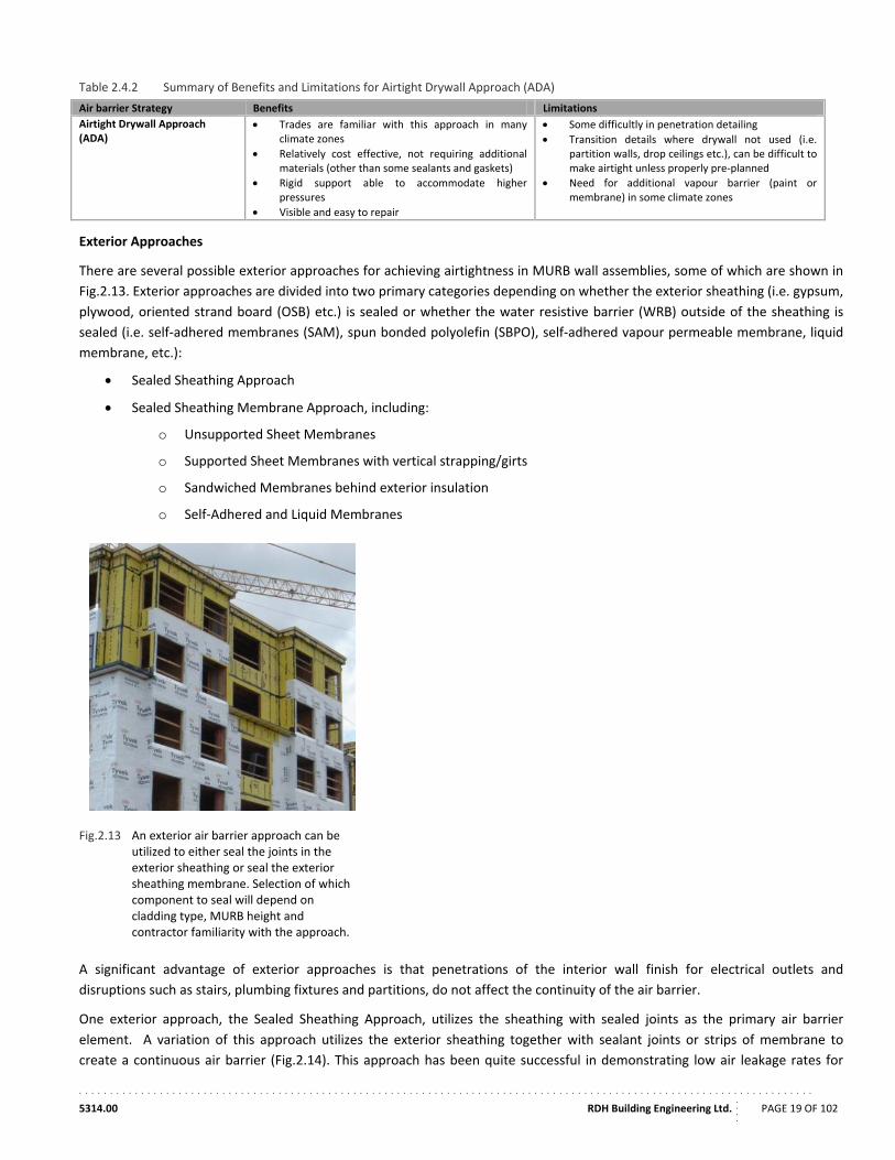
Exterior Approaches
There are several possible exterior approaches for achieving airtightness in MURB wall assemblies, some of which are shown in
Fig.2.13. Exterior approaches are divided into two primary categories depending on whether the exterior sheathing (i.e. gypsum,
plywood, oriented strand board (OSB) etc.) is sealed or whether the water resistive barrier (WRB) outside of the sheathing is
sealed (i.e. self‐adhered membranes (SAM), spun bonded polyolefin (SBPO), self‐adhered vapour permeable membrane, liquid
membrane, etc.):
Sealed Sheathing Approach
Sealed Sheathing Membrane Approach, including:
o Unsupported Sheet Membranes
o Supported Sheet Membranes with vertical strapping/girts
o Sandwiched Membranes behind exterior insulation
o Self‐Adhered and Liquid Membranes
Fig.2.13 An exterior air barrier approach can be utilized to either seal the joints in the exterior sheathing or seal the exterior sheathing membrane. Selection of which component to seal will depend on cladding type, MURB height and contractor familiarity with the approach.
A significant advantage of exterior approaches is that penetrations of the interior wall finish for electrical outlets and
disruptions such as stairs, plumbing fixtures and partitions, do not affect the continuity of the air barrier.
One exterior approach, the Sealed Sheathing Approach, utilizes the sheathing with sealed joints as the primary air barrier
element. A variation of this approach utilizes the exterior sheathing together with sealant joints or strips of membrane to
create a continuous air barrier (Fig.2.14). This approach has been quite successful in demonstrating low air leakage rates for
. . . . . . . . . . . . . . . . . . . . . . . . . . . . . . . . . . . . . . . . . . . . . . . . . . . . . . . . . . . . . . . . . . . . . . . . . . . . . . . . . . . . . . . . . . . . . . . . . . . . . . . . . . . . . . . . . . . . . .
5314.00 RDH Building Engineering Ltd.
....
PAGE 20 OF 102
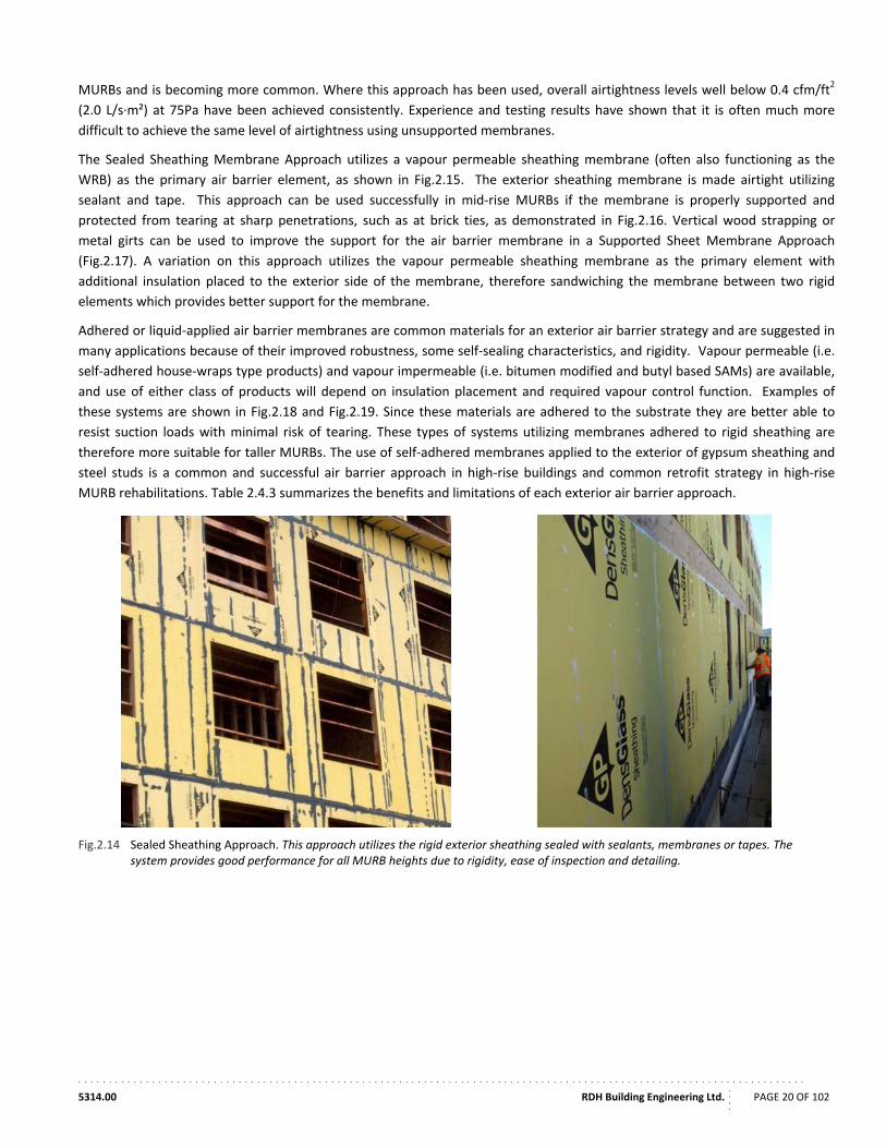
MURBs and is becoming more common. Where this approach has been used, overall airtightness levels well below 0.4 cfm/ft2
(2.0 L/s∙m²) at 75Pa have been achieved consistently. Experience and testing results have shown that it is often much more
difficult to achieve the same level of airtightness using unsupported membranes.
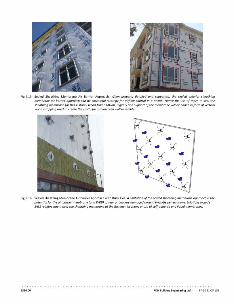
The Sealed Sheathing Membrane Approach utilizes a vapour permeable sheathing membrane (often also functioning as the
WRB) as the primary air barrier element, as shown in Fig.2.15. The exterior sheathing membrane is made airtight utilizing
sealant and tape. This approach can be used successfully in mid‐rise MURBs if the membrane is properly supported and
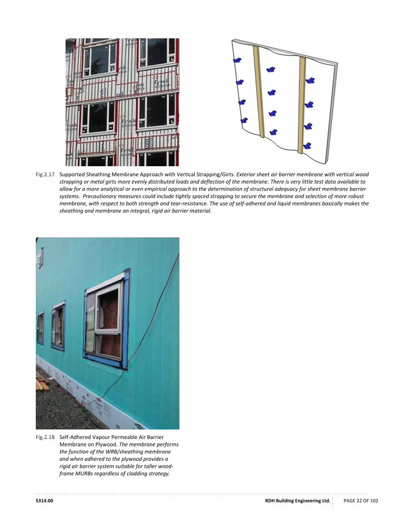
protected from tearing at sharp penetrations, such as at brick ties, as demonstrated in Fig.2.16. Vertical wood strapping or
metal girts can be used to improve the support for the air barrier membrane in a Supported Sheet Membrane Approach
(Fig.2.17). A variation on this approach utilizes the vapour permeable sheathing membrane as the primary element with
additional insulation placed to the exterior side of the membrane, therefore sandwiching the membrane between two rigid
elements which provides better support for the membrane.
Adhered or liquid‐applied air barrier membranes are common materials for an exterior air barrier strategy and are suggested in
many applications because of their improved robustness, some self‐sealing characteristics, and rigidity. Vapour permeable (i.e.
self‐adhered house‐wraps type products) and vapour impermeable (i.e. bitumen modified and butyl based SAMs) are available,
and use of either class of products will depend on insulation placement and required vapour control function. Examples of
these systems are shown in Fig.2.18 and Fig.2.19. Since these materials are adhered to the substrate they are better able to
resist suction loads with minimal risk of tearing. These types of systems utilizing membranes adhered to rigid sheathing are
therefore more suitable for taller MURBs. The use of self‐adhered membranes applied to the exterior of gypsum sheathing and
steel studs is a common and successful air barrier approach in high‐rise buildings and common retrofit strategy in high‐rise
MURB rehabilitations. Table 2.4.3 summarizes the benefits and limitations of each exterior air barrier approach.
Fig.2.14 Sealed Sheathing Approach. This approach utilizes the rigid exterior sheathing sealed with sealants, membranes or tapes. The system provides good performance for all MURB heights due to rigidity, ease of inspection and detailing.
. . . . . . . . . . . . . . . . . . . . . . . . . . . . . . . . . . . . . . . . . . . . . . . . . . . . . . . . . . . . . . . . . . . . . . . . . . . . . . . . . . . . . . . . . . . . . . . . . . . . . . . . . . . . . . . . . . . . . .
5314.00 RDH Building Engineering Ltd.
....
PAGE 21 OF 102
Fig.2.15 Sealed Sheathing Membrane Air Barrier Approach. When property detailed and supported, the sealed exterior sheathing membrane air barrier approach can be successful strategy for airflow control in a MURB. Notice the use of tapes to seal the sheathing membrane for this 4‐storey wood‐frame MURB. Rigidity and support of the membrane will be added in form of vertical wood strapping used to create the cavity for a rainscreen wall assembly.
Fig.2.16 Sealed Sheathing Membrane Air Barrier Approach with Brick Ties. A limitation of the sealed sheathing membrane approach is the potential for the air barrier membrane (and WRB) to tear or become damaged around brick‐tie penetrations. Solutions include SAM reinforcement over the sheathing membrane at the fastener locations or use of self‐adhered and liquid membranes.
. . . . . . . . . . . . . . . . . . . . . . . . . . . . . . . . . . . . . . . . . . . . . . . . . . . . . . . . . . . . . . . . . . . . . . . . . . . . . . . . . . . . . . . . . . . . . . . . . . . . . . . . . . . . . . . . . . . . . .
5314.00 RDH Building Engineering Ltd.
....
PAGE 22 OF 102
Fig.2.17 Supported Sheathing Membrane Approach with Vertical Strapping/Girts. Exterior sheet air barrier membrane with vertical wood strapping or metal girts more evenly distributed loads and deflection of the membrane. There is very little test data available to allow for a more analytical or even empirical approach to the determination of structural adequacy for sheet membrane barrier systems. Precautionary measures could include tightly spaced strapping to secure the membrane and selection of more robust membrane, with respect to both strength and tear‐resistance. The use of self‐adhered and liquid membranes basically makes the sheathing and membrane an integral, rigid air barrier material.
Fig.2.18 Self‐Adhered Vapour Permeable Air Barrier Membrane on Plywood. The membrane performs the function of the WRB/sheathing membrane and when adhered to the plywood provides a rigid air barrier system suitable for taller wood‐frame MURBs regardless of cladding strategy.
. . . . . . . . . . . . . . . . . . . . . . . . . . . . . . . . . . . . . . . . . . . . . . . . . . . . . . . . . . . . . . . . . . . . . . . . . . . . . . . . . . . . . . . . . . . . . . . . . . . . . . . . . . . . . . . . . . . . . .
5314.00 RDH Building Engineering Ltd.
....
PAGE 23 OF 102
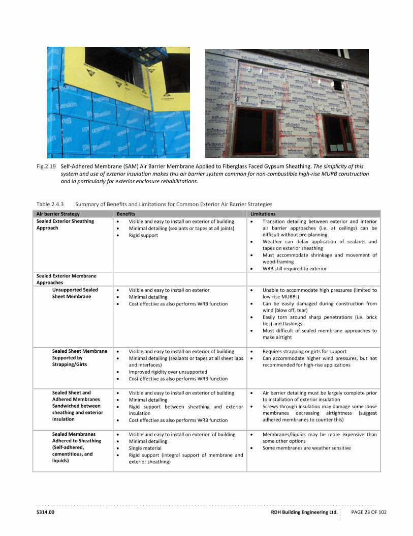
Fig.2.19 Self‐Adhered Membrane (SAM) Air Barrier Membrane Applied to Fiberglass Faced Gypsum Sheathing. The simplicity of this system and use of exterior insulation makes this air barrier system common for non‐combustible high‐rise MURB construction and in particularly for exterior enclosure rehabilitations.
Table 2.4.3 Summary of Benefits and Limitations for Common Exterior Air Barrier Strategies
Air barrier Strategy Benefits Limitations
Sealed Exterior Sheathing Approach
Visible and easy to install on exterior of building
Minimal detailing (sealants or tapes at all joints)
Rigid support
Transition detailing between exterior and interior air barrier approaches (i.e. at ceilings) can be difficult without pre‐planning
Weather can delay application of sealants and tapes on exterior sheathing
Must accommodate shrinkage and movement of wood‐framing
WRB still required to exterior
Sealed Exterior Membrane Approaches
Unsupported Sealed Sheet Membrane
Visible and easy to install on exterior
Minimal detailing
Cost effective as also performs WRB function
Unable to accommodate high pressures (limited to low‐rise MURBs)
Can be easily damaged during construction from wind (blow off, tear)
Easily torn around sharp penetrations (i.e. brick ties) and flashings
Most difficult of sealed membrane approaches to make airtight
Sealed Sheet Membrane Supported by Strapping/Girts
Visible and easy to install on exterior of building
Minimal detailing (sealants or tapes at all sheet laps and interfaces)
Improved rigidity over unsupported
Cost effective as also performs WRB function
Requires strapping or girts for support
Can accommodate higher wind pressures, but not recommended for high‐rise applications
Sealed Sheet and Adhered Membranes Sandwiched between sheathing and exterior insulation
Visible and easy to install on exterior of building
Minimal detailing
Rigid support between sheathing and exterior insulation
Cost effective as also performs WRB function
Air barrier detailing must be largely complete prior to installation of exterior insulation
Screws through insulation may damage some loose membranes decreasing airtightness (suggest adhered membranes to counter this)
Sealed Membranes Adhered to Sheathing (Self‐adhered, cementitious, and liquids)
Visible and easy to install on exterior of building
Minimal detailing
Single material
Rigid support (integral support of membrane and exterior sheathing)
Membranes/liquids may be more expensive than some other options
Some membranes are weather sensitive
. . . . . . . . . . . . . . . . . . . . . . . . . . . . . . . . . . . . . . . . . . . . . . . . . . . . . . . . . . . . . . . . . . . . . . . . . . . . . . . . . . . . . . . . . . . . . . . . . . . . . . . . . . . . . . . . . . . . . .
5314.00 RDH Building Engineering Ltd.
....
PAGE 24 OF 102
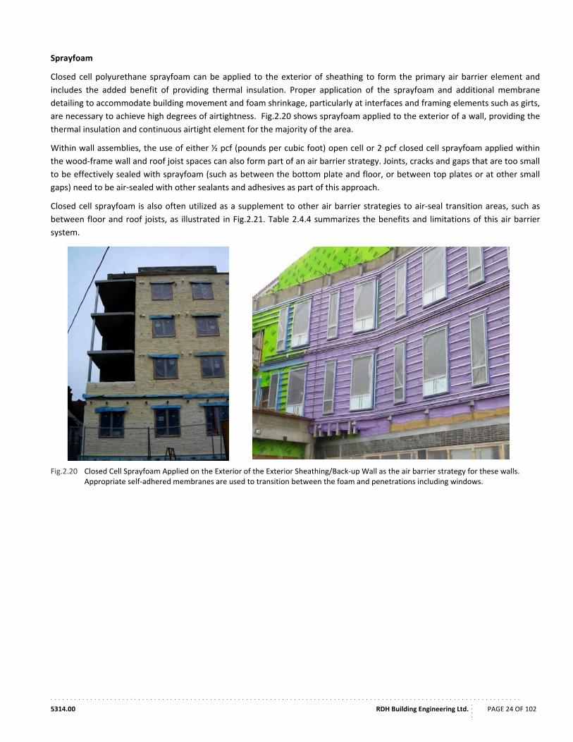
Sprayfoam
Closed cell polyurethane sprayfoam can be applied to the exterior of sheathing to form the primary air barrier element and
includes the added benefit of providing thermal insulation. Proper application of the sprayfoam and additional membrane
detailing to accommodate building movement and foam shrinkage, particularly at interfaces and framing elements such as girts,
are necessary to achieve high degrees of airtightness. Fig.2.20 shows sprayfoam applied to the exterior of a wall, providing the
thermal insulation and continuous airtight element for the majority of the area.
Within wall assemblies, the use of either ½ pcf (pounds per cubic foot) open cell or 2 pcf closed cell sprayfoam applied within
the wood‐frame wall and roof joist spaces can also form part of an air barrier strategy. Joints, cracks and gaps that are too small
to be effectively sealed with sprayfoam (such as between the bottom plate and floor, or between top plates or at other small
gaps) need to be air‐sealed with other sealants and adhesives as part of this approach.
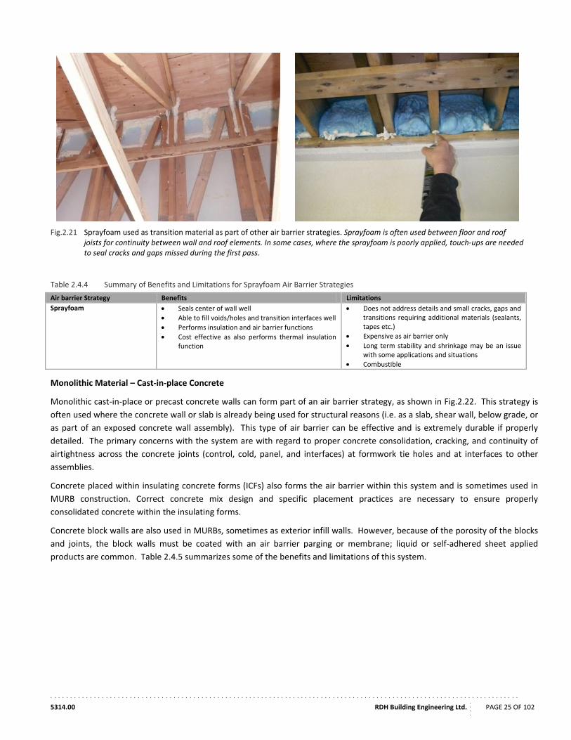
Closed cell sprayfoam is also often utilized as a supplement to other air barrier strategies to air‐seal transition areas, such as
between floor and roof joists, as illustrated in Fig.2.21. Table 2.4.4 summarizes the benefits and limitations of this air barrier
system.
Fig.2.20 Closed Cell Sprayfoam Applied on the Exterior of the Exterior Sheathing/Back‐up Wall as the air barrier strategy for these walls. Appropriate self‐adhered membranes are used to transition between the foam and penetrations including windows.
. . . . . . . . . . . . . . . . . . . . . . . . . . . . . . . . . . . . . . . . . . . . . . . . . . . . . . . . . . . . . . . . . . . . . . . . . . . . . . . . . . . . . . . . . . . . . . . . . . . . . . . . . . . . . . . . . . . . . .
5314.00 RDH Building Engineering Ltd.
....
PAGE 25 OF 102
Fig.2.21 Sprayfoam used as transition material as part of other air barrier strategies. Sprayfoam is often used between floor and roof joists for continuity between wall and roof elements. In some cases, where the sprayfoam is poorly applied, touch‐ups are needed to seal cracks and gaps missed during the first pass.
Table 2.4.4 Summary of Benefits and Limitations for Sprayfoam Air Barrier Strategies
Air barrier Strategy Benefits Limitations
Sprayfoam Seals center of wall well
Able to fill voids/holes and transition interfaces well
Performs insulation and air barrier functions
Cost effective as also performs thermal insulation function
Does not address details and small cracks, gaps and transitions requiring additional materials (sealants, tapes etc.)
Expensive as air barrier only
Long term stability and shrinkage may be an issue with some applications and situations
Combustible
Monolithic Material – Cast‐in‐place Concrete
Monolithic cast‐in‐place or precast concrete walls can form part of an air barrier strategy, as shown in Fig.2.22. This strategy is
often used where the concrete wall or slab is already being used for structural reasons (i.e. as a slab, shear wall, below grade, or
as part of an exposed concrete wall assembly). This type of air barrier can be effective and is extremely durable if properly
detailed. The primary concerns with the system are with regard to proper concrete consolidation, cracking, and continuity of
airtightness across the concrete joints (control, cold, panel, and interfaces) at formwork tie holes and at interfaces to other
assemblies.
Concrete placed within insulating concrete forms (ICFs) also forms the air barrier within this system and is sometimes used in
MURB construction. Correct concrete mix design and specific placement practices are necessary to ensure properly
consolidated concrete within the insulating forms.
Concrete block walls are also used in MURBs, sometimes as exterior infill walls. However, because of the porosity of the blocks
and joints, the block walls must be coated with an air barrier parging or membrane; liquid or self‐adhered sheet applied
products are common. Table 2.4.5 summarizes some of the benefits and limitations of this system.
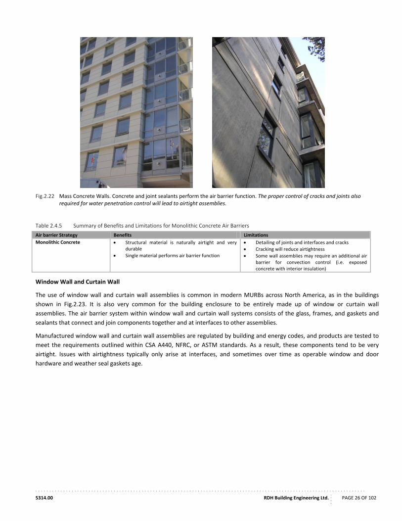
. . . . . . . . . . . . . . . . . . . . . . . . . . . . . . . . . . . . . . . . . . . . . . . . . . . . . . . . . . . . . . . . . . . . . . . . . . . . . . . . . . . . . . . . . . . . . . . . . . . . . . . . . . . . . . . . . . . . . .
5314.00 RDH Building Engineering Ltd.
....
PAGE 26 OF 102
Fig.2.22 Mass Concrete Walls. Concrete and joint sealants perform the air barrier function. The proper control of cracks and joints also required for water penetration control will lead to airtight assemblies.
Table 2.4.5 Summary of Benefits and Limitations for Monolithic Concrete Air Barriers
Air barrier Strategy Benefits Limitations
Monolithic Concrete Structural material is naturally airtight and very durable
Single material performs air barrier function
Detailing of joints and interfaces and cracks
Cracking will reduce airtightness
Some wall assemblies may require an additional air barrier for convection control (i.e. exposed concrete with interior insulation)
Window Wall and Curtain Wall
The use of window wall and curtain wall assemblies is common in modern MURBs across North America, as in the buildings
shown in Fig.2.23. It is also very common for the building enclosure to be entirely made up of window or curtain wall
assemblies. The air barrier system within window wall and curtain wall systems consists of the glass, frames, and gaskets and
sealants that connect and join components together and at interfaces to other assemblies.
Manufactured window wall and curtain wall assemblies are regulated by building and energy codes, and products are tested to
meet the requirements outlined within CSA A440, NFRC, or ASTM standards. As a result, these components tend to be very
airtight. Issues with airtightness typically only arise at interfaces, and sometimes over time as operable window and door
hardware and weather seal gaskets age.
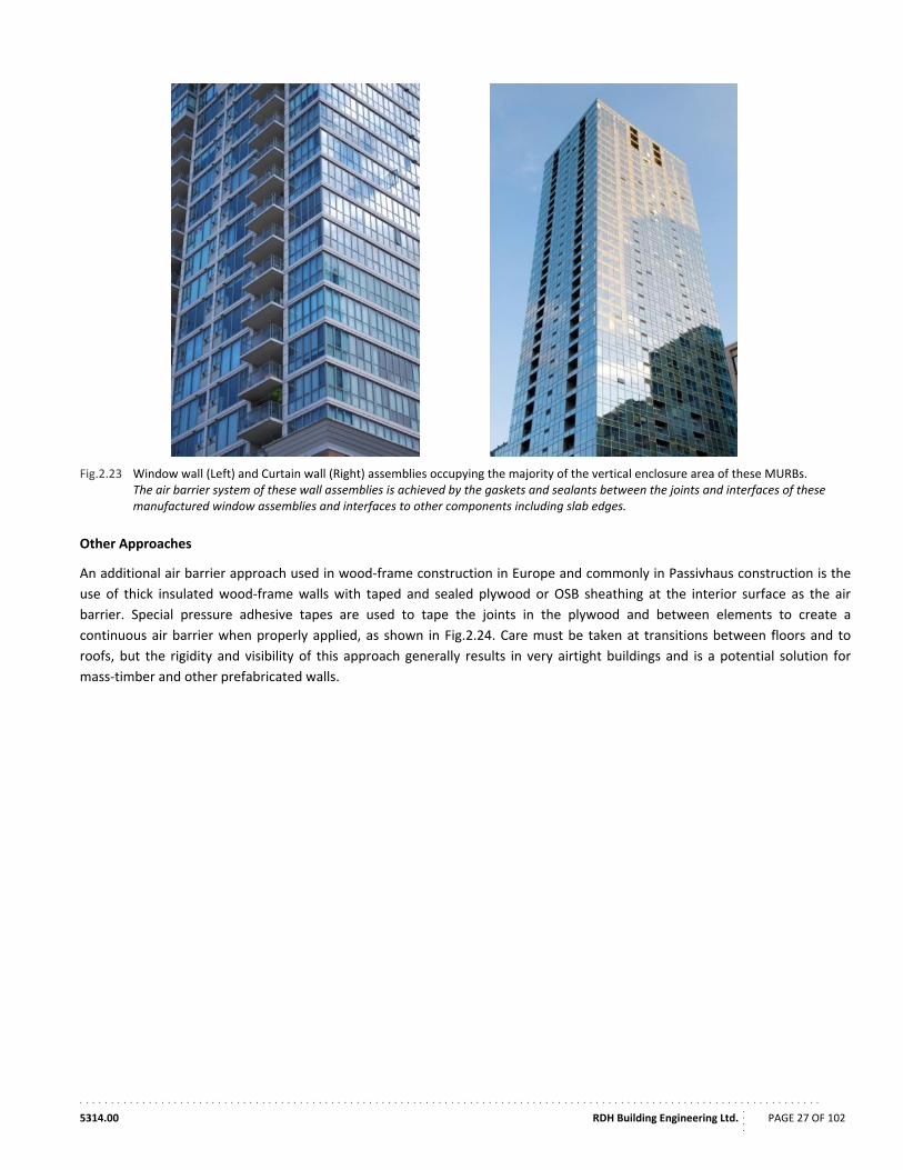
. . . . . . . . . . . . . . . . . . . . . . . . . . . . . . . . . . . . . . . . . . . . . . . . . . . . . . . . . . . . . . . . . . . . . . . . . . . . . . . . . . . . . . . . . . . . . . . . . . . . . . . . . . . . . . . . . . . . . .
5314.00 RDH Building Engineering Ltd.
....
PAGE 27 OF 102
Fig.2.23 Window wall (Left) and Curtain wall (Right) assemblies occupying the majority of the vertical enclosure area of these MURBs. The air barrier system of these wall assemblies is achieved by the gaskets and sealants between the joints and interfaces of these manufactured window assemblies and interfaces to other components including slab edges.
Other Approaches
An additional air barrier approach used in wood‐frame construction in Europe and commonly in Passivhaus construction is the
use of thick insulated wood‐frame walls with taped and sealed plywood or OSB sheathing at the interior surface as the air
barrier. Special pressure adhesive tapes are used to tape the joints in the plywood and between elements to create a
continuous air barrier when properly applied, as shown in Fig.2.24. Care must be taken at transitions between floors and to
roofs, but the rigidity and visibility of this approach generally results in very airtight buildings and is a potential solution for
mass‐timber and other prefabricated walls.
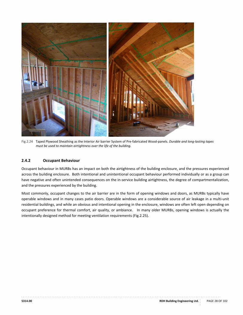
. . . . . . . . . . . . . . . . . . . . . . . . . . . . . . . . . . . . . . . . . . . . . . . . . . . . . . . . . . . . . . . . . . . . . . . . . . . . . . . . . . . . . . . . . . . . . . . . . . . . . . . . . . . . . . . . . . . . . .
5314.00 RDH Building Engineering Ltd.
....
PAGE 28 OF 102
Fig.2.24 Taped Plywood Sheathing as the Interior Air barrier System of Pre‐fabricated Wood‐panels. Durable and long‐lasting tapes must be used to maintain airtightness over the life of the building.
2.4.2 Occupant Behaviour
Occupant behaviour in MURBs has an impact on both the airtightness of the building enclosure, and the pressures experienced
across the building enclosure. Both intentional and unintentional occupant behaviour performed individually or as a group can
have negative and often unintended consequences on the in‐service building airtightness, the degree of compartmentalization,
and the pressures experienced by the building.
Most commonly, occupant changes to the air barrier are in the form of opening windows and doors, as MURBs typically have
operable windows and in many cases patio doors. Operable windows are a considerable source of air leakage in a multi‐unit
residential buildings, and while an obvious and intentional opening in the enclosure, windows are often left open depending on
occupant preference for thermal comfort, air quality, or ambiance. In many older MURBs, opening windows is actually the
intentionally designed method for meeting ventilation requirements (Fig.2.25).
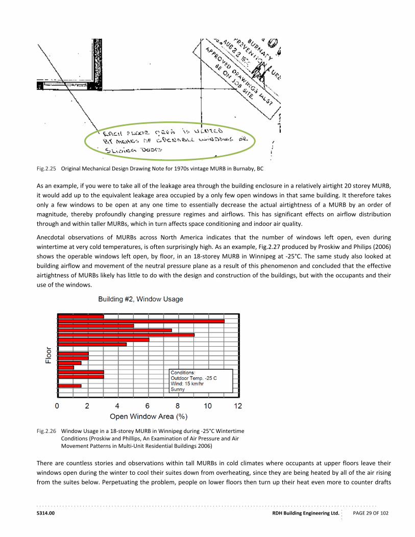
. . . . . . . . . . . . . . . . . . . . . . . . . . . . . . . . . . . . . . . . . . . . . . . . . . . . . . . . . . . . . . . . . . . . . . . . . . . . . . . . . . . . . . . . . . . . . . . . . . . . . . . . . . . . . . . . . . . . . .
5314.00 RDH Building Engineering Ltd.
....
PAGE 29 OF 102
Fig.2.25 Original Mechanical Design Drawing Note for 1970s vintage MURB in Burnaby, BC
As an example, if you were to take all of the leakage area through the building enclosure in a relatively airtight 20 storey MURB,
it would add up to the equivalent leakage area occupied by a only few open windows in that same building. It therefore takes
only a few windows to be open at any one time to essentially decrease the actual airtightness of a MURB by an order of
magnitude, thereby profoundly changing pressure regimes and airflows. This has significant effects on airflow distribution
through and within taller MURBs, which in turn affects space conditioning and indoor air quality.
Anecdotal observations of MURBs across North America indicates that the number of windows left open, even during
wintertime at very cold temperatures, is often surprisingly high. As an example, Fig.2.27 produced by Proskiw and Philips (2006)
shows the operable windows left open, by floor, in an 18‐storey MURB in Winnipeg at ‐25°C. The same study also looked at
building airflow and movement of the neutral pressure plane as a result of this phenomenon and concluded that the effective
airtightness of MURBs likely has little to do with the design and construction of the buildings, but with the occupants and their
use of the windows.
Fig.2.26 Window Usage in a 18‐storey MURB in Winnipeg during ‐25°C Wintertime Conditions (Proskiw and Phillips, An Examination of Air Pressure and Air Movement Patterns in Multi‐Unit Residential Buildings 2006)
There are countless stories and observations within tall MURBs in cold climates where occupants at upper floors leave their
windows open during the winter to cool their suites down from overheating, since they are being heated by all of the air rising
from the suites below. Perpetuating the problem, people on lower floors then turn up their heat even more to counter drafts
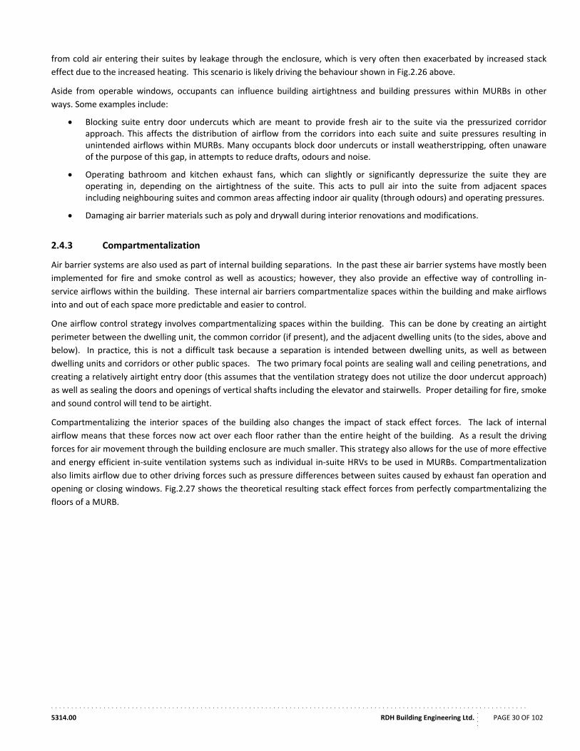
. . . . . . . . . . . . . . . . . . . . . . . . . . . . . . . . . . . . . . . . . . . . . . . . . . . . . . . . . . . . . . . . . . . . . . . . . . . . . . . . . . . . . . . . . . . . . . . . . . . . . . . . . . . . . . . . . . . . . .
5314.00 RDH Building Engineering Ltd.
....
PAGE 30 OF 102
from cold air entering their suites by leakage through the enclosure, which is very often then exacerbated by increased stack
effect due to the increased heating. This scenario is likely driving the behaviour shown in Fig.2.26 above.
Aside from operable windows, occupants can influence building airtightness and building pressures within MURBs in other
ways. Some examples include:
Blocking suite entry door undercuts which are meant to provide fresh air to the suite via the pressurized corridor approach. This affects the distribution of airflow from the corridors into each suite and suite pressures resulting in unintended airflows within MURBs. Many occupants block door undercuts or install weatherstripping, often unaware of the purpose of this gap, in attempts to reduce drafts, odours and noise.
Operating bathroom and kitchen exhaust fans, which can slightly or significantly depressurize the suite they are operating in, depending on the airtightness of the suite. This acts to pull air into the suite from adjacent spaces including neighbouring suites and common areas affecting indoor air quality (through odours) and operating pressures.
Damaging air barrier materials such as poly and drywall during interior renovations and modifications.
2.4.3 Compartmentalization
Air barrier systems are also used as part of internal building separations. In the past these air barrier systems have mostly been
implemented for fire and smoke control as well as acoustics; however, they also provide an effective way of controlling in‐
service airflows within the building. These internal air barriers compartmentalize spaces within the building and make airflows
into and out of each space more predictable and easier to control.
One airflow control strategy involves compartmentalizing spaces within the building. This can be done by creating an airtight
perimeter between the dwelling unit, the common corridor (if present), and the adjacent dwelling units (to the sides, above and
below). In practice, this is not a difficult task because a separation is intended between dwelling units, as well as between
dwelling units and corridors or other public spaces. The two primary focal points are sealing wall and ceiling penetrations, and
creating a relatively airtight entry door (this assumes that the ventilation strategy does not utilize the door undercut approach)
as well as sealing the doors and openings of vertical shafts including the elevator and stairwells. Proper detailing for fire, smoke
and sound control will tend to be airtight.
Compartmentalizing the interior spaces of the building also changes the impact of stack effect forces. The lack of internal
airflow means that these forces now act over each floor rather than the entire height of the building. As a result the driving
forces for air movement through the building enclosure are much smaller. This strategy also allows for the use of more effective
and energy efficient in‐suite ventilation systems such as individual in‐suite HRVs to be used in MURBs. Compartmentalization
also limits airflow due to other driving forces such as pressure differences between suites caused by exhaust fan operation and
opening or closing windows. Fig.2.27 shows the theoretical resulting stack effect forces from perfectly compartmentalizing the
floors of a MURB.
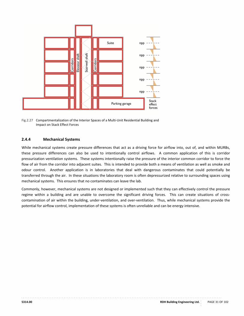
. . . . . . . . . . . . . . . . . . . . . . . . . . . . . . . . . . . . . . . . . . . . . . . . . . . . . . . . . . . . . . . . . . . . . . . . . . . . . . . . . . . . . . . . . . . . . . . . . . . . . . . . . . . . . . . . . . . . . .
5314.00 RDH Building Engineering Ltd.
....
PAGE 31 OF 102
Fig.2.27 Compartmentalization of the Interior Spaces of a Multi‐Unit Residential Building and Impact on Stack Effect Forces
2.4.4 Mechanical Systems
While mechanical systems create pressure differences that act as a driving force for airflow into, out of, and within MURBs,
these pressure differences can also be used to intentionally control airflows. A common application of this is corridor
pressurization ventilation systems. These systems intentionally raise the pressure of the interior common corridor to force the
flow of air from the corridor into adjacent suites. This is intended to provide both a means of ventilation as well as smoke and
odour control. Another application is in laboratories that deal with dangerous contaminates that could potentially be
transferred through the air. In these situations the laboratory room is often depressurized relative to surrounding spaces using
mechanical systems. This ensures that no contaminates can leave the lab.
Commonly, however, mechanical systems are not designed or implemented such that they can effectively control the pressure
regime within a building and are unable to overcome the significant driving forces. This can create situations of cross‐
contamination of air within the building, under‐ventilation, and over‐ventilation. Thus, while mechanical systems provide the
potential for airflow control, implementation of these systems is often unreliable and can be energy intensive.
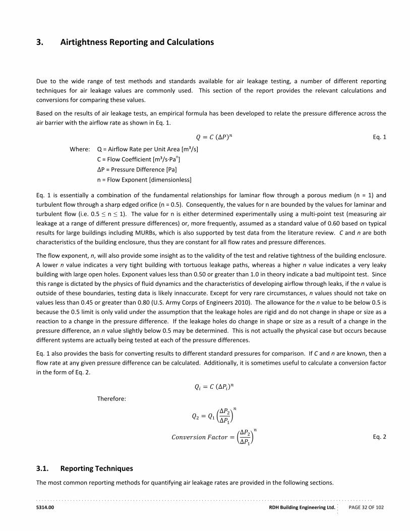
. . . . . . . . . . . . . . . . . . . . . . . . . . . . . . . . . . . . . . . . . . . . . . . . . . . . . . . . . . . . . . . . . . . . . . . . . . . . . . . . . . . . . . . . . . . . . . . . . . . . . . . . . . . . . . . . . . . . . .
5314.00 RDH Building Engineering Ltd.
....
PAGE 32 OF 102
3. Airtightness Reporting and Calculations
Due to the wide range of test methods and standards available for air leakage testing, a number of different reporting
techniques for air leakage values are commonly used. This section of the report provides the relevant calculations and
conversions for comparing these values.
Based on the results of air leakage tests, an empirical formula has been developed to relate the pressure difference across the
air barrier with the airflow rate as shown in Eq. 1.
∆ Eq. 1
Where: Q = Airflow Rate per Unit Area [m³/s]
C = Flow Coefficient [m³/s∙Pan]
ΔP = Pressure Difference [Pa]
n = Flow Exponent [dimensionless]
Eq. 1 is essentially a combination of the fundamental relationships for laminar flow through a porous medium (n = 1) and
turbulent flow through a sharp edged orifice (n = 0.5). Consequently, the values for n are bounded by the values for laminar and
turbulent flow (i.e. 0.5 ≤ n ≤ 1). The value for n is either determined experimentally using a multi‐point test (measuring air
leakage at a range of different pressure differences) or, more frequently, assumed as a standard value of 0.60 based on typical
results for large buildings including MURBs, which is also supported by test data from the literature review. C and n are both
characteristics of the building enclosure, thus they are constant for all flow rates and pressure differences.
The flow exponent, n, will also provide some insight as to the validity of the test and relative tightness of the building enclosure.
A lower n value indicates a very tight building with tortuous leakage paths, whereas a higher n value indicates a very leaky
building with large open holes. Exponent values less than 0.50 or greater than 1.0 in theory indicate a bad multipoint test. Since
this range is dictated by the physics of fluid dynamics and the characteristics of developing airflow through leaks, if the n value is
outside of these boundaries, testing data is likely innaccurate. Except for very rare circumstances, n values should not take on
values less than 0.45 or greater than 0.80 (U.S. Army Corps of Engineers 2010). The allowance for the n value to be below 0.5 is
because the 0.5 limit is only valid under the assumption that the leakage holes are rigid and do not change in shape or size as a
reaction to a change in the pressure difference. If the leakage holes do change in shape or size as a result of a change in the
pressure difference, an n value slightly below 0.5 may be determined. This is not actually the physical case but occurs because
different systems are actually being tested at each of the pressure differences.
Eq. 1 also provides the basis for converting results to different standard pressures for comparison. If C and n are known, then a
flow rate at any given pressure difference can be calculated. Additionally, it is sometimes useful to calculate a conversion factor
in the form of Eq. 2.
∆
Therefore:
∆∆
∆∆
Eq. 2
3.1. Reporting Techniques
The most common reporting methods for quantifying air leakage rates are provided in the following sections.
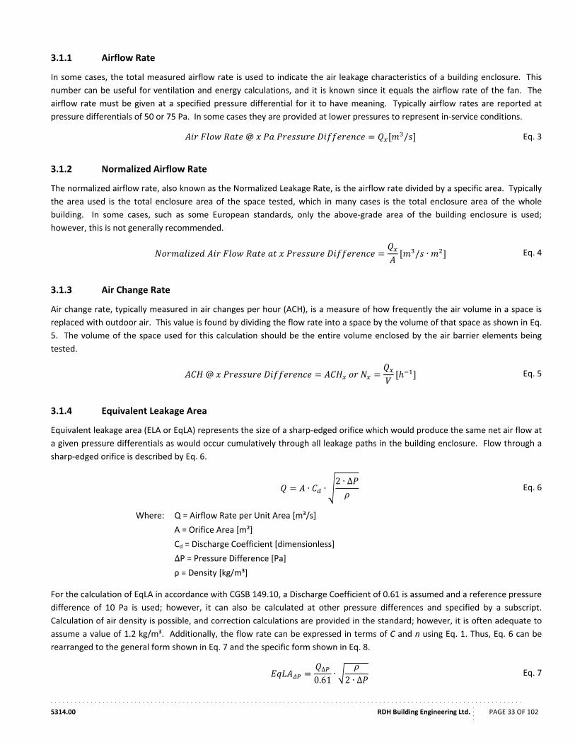
. . . . . . . . . . . . . . . . . . . . . . . . . . . . . . . . . . . . . . . . . . . . . . . . . . . . . . . . . . . . . . . . . . . . . . . . . . . . . . . . . . . . . . . . . . . . . . . . . . . . . . . . . . . . . . . . . . . . . .
5314.00 RDH Building Engineering Ltd.
....
PAGE 33 OF 102
3.1.1 Airflow Rate
In some cases, the total measured airflow rate is used to indicate the air leakage characteristics of a building enclosure. This
number can be useful for ventilation and energy calculations, and it is known since it equals the airflow rate of the fan. The
airflow rate must be given at a specified pressure differential for it to have meaning. Typically airflow rates are reported at
pressure differentials of 50 or 75 Pa. In some cases they are provided at lower pressures to represent in‐service conditions.
@ / Eq. 3
3.1.2 Normalized Airflow Rate
The normalized airflow rate, also known as the Normalized Leakage Rate, is the airflow rate divided by a specific area. Typically
the area used is the total enclosure area of the space tested, which in many cases is the total enclosure area of the whole
building. In some cases, such as some European standards, only the above‐grade area of the building enclosure is used;
however, this is not generally recommended.
/ ∙ Eq. 4
3.1.3 Air Change Rate
Air change rate, typically measured in air changes per hour (ACH), is a measure of how frequently the air volume in a space is
replaced with outdoor air. This value is found by dividing the flow rate into a space by the volume of that space as shown in Eq.
5. The volume of the space used for this calculation should be the entire volume enclosed by the air barrier elements being
tested.
@ Eq. 5
3.1.4 Equivalent Leakage Area
Equivalent leakage area (ELA or EqLA) represents the size of a sharp‐edged orifice which would produce the same net air flow at
a given pressure differentials as would occur cumulatively through all leakage paths in the building enclosure. Flow through a
sharp‐edged orifice is described by Eq. 6.
∙ ∙2 ∙ ∆
Eq. 6
Where: Q = Airflow Rate per Unit Area [m³/s]
A = Orifice Area [m²]
Cd = Discharge Coefficient [dimensionless]
ΔP = Pressure Difference [Pa]
ρ = Density [kg/m³]
For the calculation of EqLA in accordance with CGSB 149.10, a Discharge Coefficient of 0.61 is assumed and a reference pressure
difference of 10 Pa is used; however, it can also be calculated at other pressure differences and specified by a subscript.
Calculation of air density is possible, and correction calculations are provided in the standard; however, it is often adequate to
assume a value of 1.2 kg/m³. Additionally, the flow rate can be expressed in terms of C and n using Eq. 1. Thus, Eq. 6 can be
rearranged to the general form shown in Eq. 7 and the specific form shown in Eq. 8.
∆
0.61∙2 ∙ ∆
Eq. 7
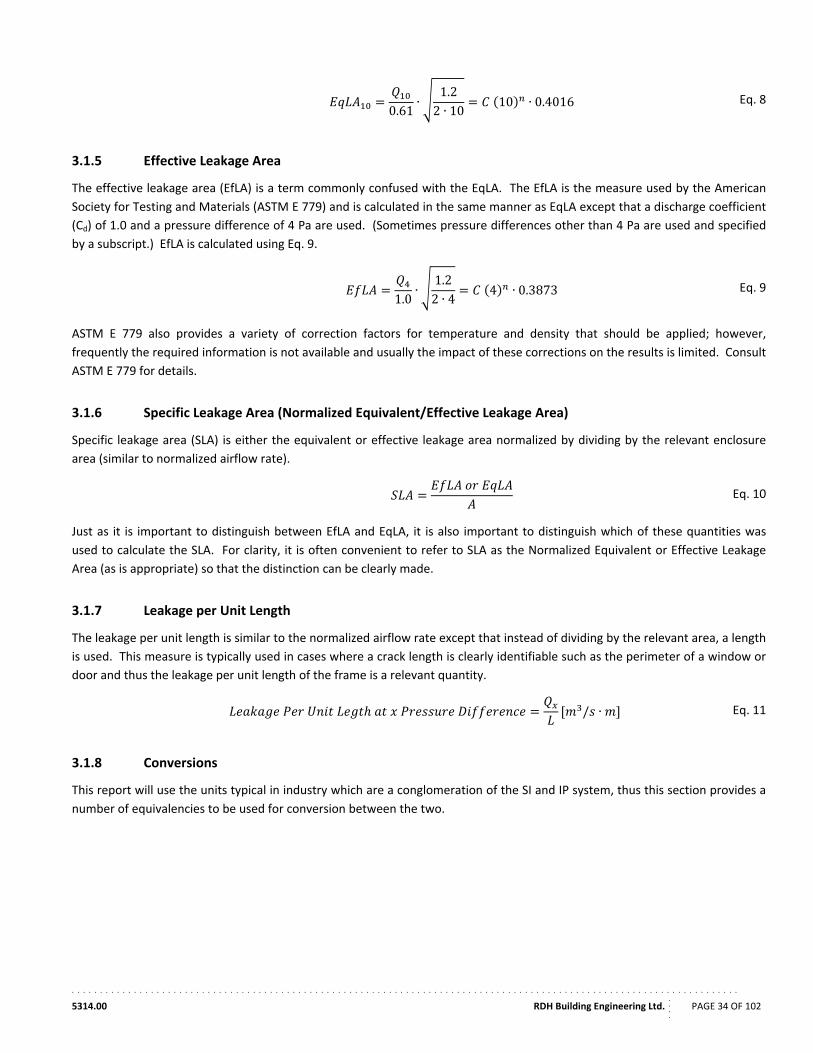
. . . . . . . . . . . . . . . . . . . . . . . . . . . . . . . . . . . . . . . . . . . . . . . . . . . . . . . . . . . . . . . . . . . . . . . . . . . . . . . . . . . . . . . . . . . . . . . . . . . . . . . . . . . . . . . . . . . . . .
5314.00 RDH Building Engineering Ltd.
....
PAGE 34 OF 102
0.61∙
1.22 ∙ 10
10 ∙ 0.4016 Eq. 8
3.1.5 Effective Leakage Area
The effective leakage area (EfLA) is a term commonly confused with the EqLA. The EfLA is the measure used by the American
Society for Testing and Materials (ASTM E 779) and is calculated in the same manner as EqLA except that a discharge coefficient
(Cd) of 1.0 and a pressure difference of 4 Pa are used. (Sometimes pressure differences other than 4 Pa are used and specified
by a subscript.) EfLA is calculated using Eq. 9.
1.0∙
1.22 ∙ 4
4 ∙ 0.3873 Eq. 9
ASTM E 779 also provides a variety of correction factors for temperature and density that should be applied; however,
frequently the required information is not available and usually the impact of these corrections on the results is limited. Consult
ASTM E 779 for details.
3.1.6 Specific Leakage Area (Normalized Equivalent/Effective Leakage Area)
Specific leakage area (SLA) is either the equivalent or effective leakage area normalized by dividing by the relevant enclosure
area (similar to normalized airflow rate).
Eq. 10
Just as it is important to distinguish between EfLA and EqLA, it is also important to distinguish which of these quantities was
used to calculate the SLA. For clarity, it is often convenient to refer to SLA as the Normalized Equivalent or Effective Leakage
Area (as is appropriate) so that the distinction can be clearly made.
3.1.7 Leakage per Unit Length
The leakage per unit length is similar to the normalized airflow rate except that instead of dividing by the relevant area, a length
is used. This measure is typically used in cases where a crack length is clearly identifiable such as the perimeter of a window or
door and thus the leakage per unit length of the frame is a relevant quantity.
/ ∙ Eq. 11
3.1.8 Conversions
This report will use the units typical in industry which are a conglomeration of the SI and IP system, thus this section provides a
number of equivalencies to be used for conversion between the two.
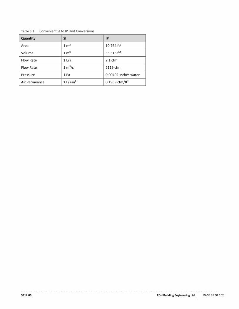
. . . . . . . . . . . . . . . . . . . . . . . . . . . . . . . . . . . . . . . . . . . . . . . . . . . . . . . . . . . . . . . . . . . . . . . . . . . . . . . . . . . . . . . . . . . . . . . . . . . . . . . . . . . . . . . . . . . . . .
5314.00 RDH Building Engineering Ltd.
....
PAGE 35 OF 102
Table 3.1 Convenient SI to IP Unit Conversions
Quantity SI IP
Area 1 m² 10.764 ft²
Volume 1 m³ 35.315 ft³
Flow Rate 1 L/s 2.1 cfm
Flow Rate 1 m3/s 2119 cfm
Pressure 1 Pa 0.00402 inches water
Air Permeance 1 L/s∙m² 0.1969 cfm/ft²
. . . . . . . . . . . . . . . . . . . . . . . . . . . . . . . . . . . . . . . . . . . . . . . . . . . . . . . . . . . . . . . . . . . . . . . . . . . . . . . . . . . . . . . . . . . . . . . . . . . . . . . . . . . . . . . . . . . . . .
5314.00 RDH Building Engineering Ltd.
....
PAGE 36 OF 102
4. Literature Review Summary
There are many good sources of North American and international information on air leakage test methods, specifications, and
case‐studies of large buildings including MURBs. Using the original CMHC research report Air Leakage Characteristics, Test
Methods and Specifications for Large Buildings (2001) as a starting point, the literature review was expanded and updated to
include past references and many other references from the last decade that were not captured by the earlier report. Over the
past decade, a number of large buildings have been tested by many organizations, including our project team members. A list of
references and a bibliography are provided at the end of this report.
While information collected through the literature review process is presented throughout this report, overall, the literature
review identified the following key points with respect to airtightness in MURBs.
Equipment
Quantitative testing requires specialized equipment; however, the equipment required to effectively test MURB airtightness exists and is readily available throughout Canada, the United States, and most of the developed world.
Airtightness testing equipment has not changed significantly in the last 10 years (time of previous report), other than improvements in technology and the ability to control fans and collect data more easily using computer software. Wireless technology is also starting to be used to transmit data when using multiple fan‐door setups.
A variety of equipment can be used for qualitative testing including smoke generators, smoke pencils, and infrared cameras. Further discussion of these and other types of equipment is provided in Section 5.6.
Testing
Numerous whole building test procedures exist; however, no standard development agency has created a standard method for balanced fan pressurization/depressurization testing of a single space within a larger building, which is one of the most relevant test methods for MURBs and described by a number of sources.
The air barriers of large buildings in Canada and the United States are not commonly tested, and even less frequently for MURBs. The exceptions are the US Army Corps of Engineers, which requires testing of all of its new buildings, and the State of Washington, which has also implemented mandatory testing.
Testing can be performed to determine if a building meets a specified performance criteria, as a quality control measure during construction, to locate source of air leakage, to enable quantitative comparisons of building performance, to determine if other forms of airflow control such as mechanical system could potentially be used, and to develop calibrated airflow models of existing buildings.
Additional information regarding testing procedures is provided in Section 5.
Performance
Air leakage performance ranges widely between buildings. More information is provided in Section 5.7 where airtightness standards are reviewed and Section 7 which includes analysis of the MURB airtightness database.
If attention is paid to the air barrier design and installation, airtightness can be improved significantly compared to standard practice. Highly airtight buildings are possible.
Preventing air infiltration by means of mechanical pressurization can significantly increase energy consumption.
MURBs are significantly different from comparably‐sized commercial buildings because they usually have operable windows, which can significantly impact the airflow and pressure regimes in to, out of, and within the building.
A wide variety of metrics are used to specify airtightness of building. Further discussion of this was provided in Section 3 of this report.
As part of the literature review, a database was created of air leakage characteristics for MURBs including enclosure airtightness
and other relevant building characteristics. The database is populated from available published data, as well as unpublished
. . . . . . . . . . . . . . . . . . . . . . . . . . . . . . . . . . . . . . . . . . . . . . . . . . . . . . . . . . . . . . . . . . . . . . . . . . . . . . . . . . . . . . . . . . . . . . . . . . . . . . . . . . . . . . . . . . . . . .
5314.00 RDH Building Engineering Ltd.
....
PAGE 37 OF 102
datasets maintained by several of the study partners. Data for air leakage measurements is reported in a variety of units and
measures including air exchange rates, flow rates normalized per enclosure area, and equivalent leakage areas. The data is
provided in standard units where sufficient test information is available to convert the data. It is intended that this database be
continually updated so that relevant and accurate MURB airtightness testing data is available for both practitioners and policy
makers. To facilitate this, a data entry form has been created that can be filled out by airtightness testers and then input into
the database, a copy of which is included in Appendix C. A summary of the database is included in Appendix A, and an analysis
of the data is provided in a later section of this report.
. . . . . . . . . . . . . . . . . . . . . . . . . . . . . . . . . . . . . . . . . . . . . . . . . . . . . . . . . . . . . . . . . . . . . . . . . . . . . . . . . . . . . . . . . . . . . . . . . . . . . . . . . . . . . . . . . . . . . .
5314.00 RDH Building Engineering Ltd.
....
PAGE 38 OF 102
5. Test Procedures and Equipment
Airtightness testing is an important tool for evaluating the effectiveness of air barrier assemblies. It can be used as part of the
quality control measures during construction, commissioning practices near the end of construction, energy auditing, and
forensic investigations. Quantitative airtightness testing provides values for comparison with specified targets, standards, and
industry averages, while qualitative testing provides a useful forensic tool for visually determining the location, direction, and
magnitude of airflows.
5.1. System Quantitative Tests
The most common quantitative test method used to measure the air leakage of the building enclosure is by using a single fan‐
door (a.k.a. blower door) inserted into a doorway of the building to pressurize or depressurize the whole building. The pressure
differential created is of sufficient magnitude to make naturally occurring pressure differentials insignificant to the test result.
The airflow rate through the blower door is measured at various indoor to outdoor pressure differentials. This information is
then used to characterize the building’s airtightness. This test works well for smaller, single‐zone, single level buildings;
however, for large multi‐storey buildings, air‐leaky buildings, and compartmentalized multi‐unit buildings, it may not be possible
to equally pressurize (or even adequately pressurize) the entire building enclosure.
To overcome some of these issues, test methods have been adapted for complicated buildings such that they can be tested in
smaller sections (i.e. by floor or by suite) using areas that are more manageable. When testing only a portion of a building, the
air leakage through interior surfaces adjacent to the test area (i.e. suite demising walls, corridor walls, floors, and ceilings.) is
very significant but can be eliminated by pressure neutralizing interior surfaces using additional fan‐doors. Pressure neutralized
air leakage testing can be more time consuming, but also produces more useful results as it provides data on air leakage
through the exterior enclosure, and also through interior walls and floors.
Fig.5.1 presents a representative schematic showing the airflows and testing for a tall MURB at once versus the testing of a
compartmentalized section of a MURB using pressure neutralizing techniques (i.e. by floor or by suite).
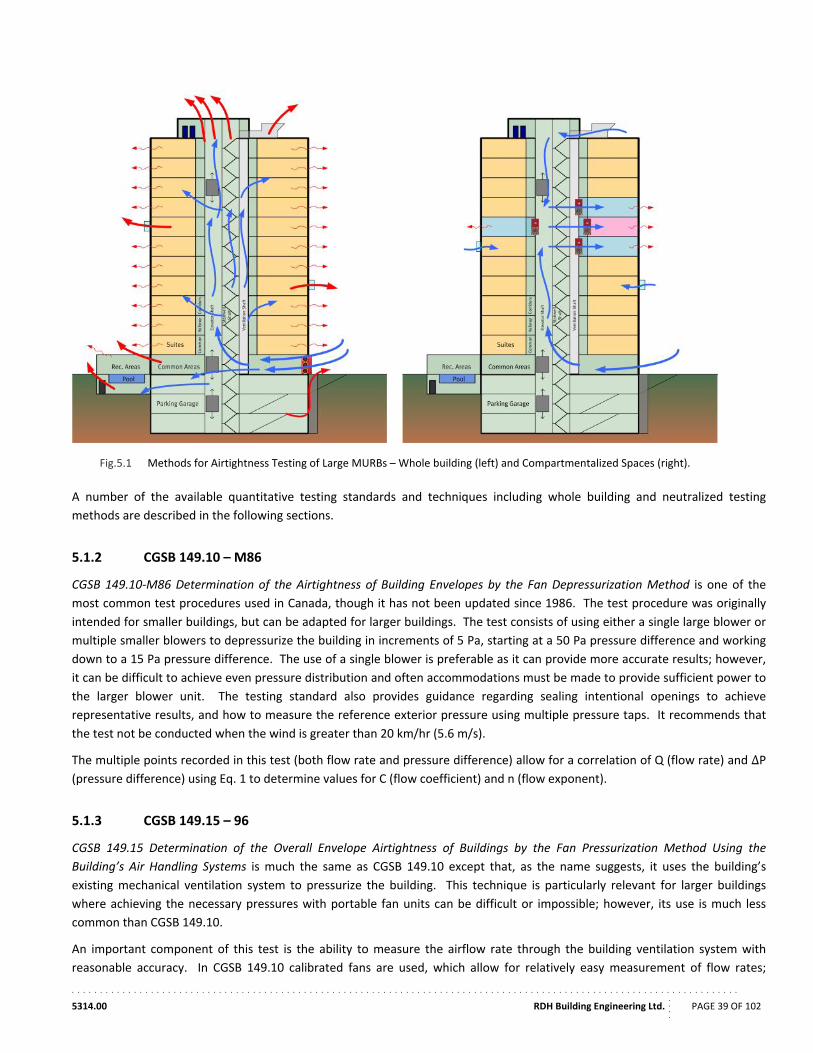
. . . . . . . . . . . . . . . . . . . . . . . . . . . . . . . . . . . . . . . . . . . . . . . . . . . . . . . . . . . . . . . . . . . . . . . . . . . . . . . . . . . . . . . . . . . . . . . . . . . . . . . . . . . . . . . . . . . . . .
5314.00 RDH Building Engineering Ltd.
....
PAGE 39 OF 102
Fig.5.1 Methods for Airtightness Testing of Large MURBs – Whole building (left) and Compartmentalized Spaces (right).
A number of the available quantitative testing standards and techniques including whole building and neutralized testing
methods are described in the following sections.
5.1.2 CGSB 149.10 – M86
CGSB 149.10‐M86 Determination of the Airtightness of Building Envelopes by the Fan Depressurization Method is one of the
most common test procedures used in Canada, though it has not been updated since 1986. The test procedure was originally
intended for smaller buildings, but can be adapted for larger buildings. The test consists of using either a single large blower or
multiple smaller blowers to depressurize the building in increments of 5 Pa, starting at a 50 Pa pressure difference and working
down to a 15 Pa pressure difference. The use of a single blower is preferable as it can provide more accurate results; however,
it can be difficult to achieve even pressure distribution and often accommodations must be made to provide sufficient power to
the larger blower unit. The testing standard also provides guidance regarding sealing intentional openings to achieve
representative results, and how to measure the reference exterior pressure using multiple pressure taps. It recommends that
the test not be conducted when the wind is greater than 20 km/hr (5.6 m/s).
The multiple points recorded in this test (both flow rate and pressure difference) allow for a correlation of Q (flow rate) and ΔP (pressure difference) using Eq. 1 to determine values for C (flow coefficient) and n (flow exponent).
5.1.3 CGSB 149.15 – 96
CGSB 149.15 Determination of the Overall Envelope Airtightness of Buildings by the Fan Pressurization Method Using the
Building’s Air Handling Systems is much the same as CGSB 149.10 except that, as the name suggests, it uses the building’s
existing mechanical ventilation system to pressurize the building. This technique is particularly relevant for larger buildings
where achieving the necessary pressures with portable fan units can be difficult or impossible; however, its use is much less
common than CGSB 149.10.
An important component of this test is the ability to measure the airflow rate through the building ventilation system with
reasonable accuracy. In CGSB 149.10 calibrated fans are used, which allow for relatively easy measurement of flow rates;
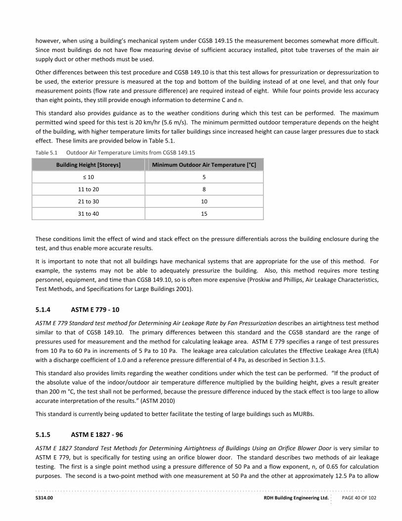
. . . . . . . . . . . . . . . . . . . . . . . . . . . . . . . . . . . . . . . . . . . . . . . . . . . . . . . . . . . . . . . . . . . . . . . . . . . . . . . . . . . . . . . . . . . . . . . . . . . . . . . . . . . . . . . . . . . . . .
5314.00 RDH Building Engineering Ltd.
....
PAGE 40 OF 102
however, when using a building’s mechanical system under CGSB 149.15 the measurement becomes somewhat more difficult.
Since most buildings do not have flow measuring devise of sufficient accuracy installed, pitot tube traverses of the main air
supply duct or other methods must be used.
Other differences between this test procedure and CGSB 149.10 is that this test allows for pressurization or depressurization to
be used, the exterior pressure is measured at the top and bottom of the building instead of at one level, and that only four
measurement points (flow rate and pressure difference) are required instead of eight. While four points provide less accuracy
than eight points, they still provide enough information to determine C and n.
This standard also provides guidance as to the weather conditions during which this test can be performed. The maximum
permitted wind speed for this test is 20 km/hr (5.6 m/s). The minimum permitted outdoor temperature depends on the height
of the building, with higher temperature limits for taller buildings since increased height can cause larger pressures due to stack
effect. These limits are provided below in Table 5.1.
Table 5.1 Outdoor Air Temperature Limits from CGSB 149.15
Building Height [Storeys] Minimum Outdoor Air Temperature [°C]
≤ 10 5
11 to 20 8
21 to 30 10
31 to 40 15
These conditions limit the effect of wind and stack effect on the pressure differentials across the building enclosure during the
test, and thus enable more accurate results.
It is important to note that not all buildings have mechanical systems that are appropriate for the use of this method. For
example, the systems may not be able to adequately pressurize the building. Also, this method requires more testing
personnel, equipment, and time than CGSB 149.10, so is often more expensive (Proskiw and Phillips, Air Leakage Characteristics,
Test Methods, and Specifications for Large Buildings 2001).
5.1.4 ASTM E 779 ‐ 10
ASTM E 779 Standard test method for Determining Air Leakage Rate by Fan Pressurization describes an airtightness test method
similar to that of CGSB 149.10. The primary differences between this standard and the CGSB standard are the range of
pressures used for measurement and the method for calculating leakage area. ASTM E 779 specifies a range of test pressures
from 10 Pa to 60 Pa in increments of 5 Pa to 10 Pa. The leakage area calculation calculates the Effective Leakage Area (EfLA)
with a discharge coefficient of 1.0 and a reference pressure differential of 4 Pa, as described in Section 3.1.5.
This standard also provides limits regarding the weather conditions under which the test can be performed. “If the product of
the absolute value of the indoor/outdoor air temperature difference multiplied by the building height, gives a result greater
than 200 m °C, the test shall not be performed, because the pressure difference induced by the stack effect is too large to allow
accurate interpretation of the results.” (ASTM 2010)
This standard is currently being updated to better facilitate the testing of large buildings such as MURBs.
5.1.5 ASTM E 1827 ‐ 96
ASTM E 1827 Standard Test Methods for Determining Airtightness of Buildings Using an Orifice Blower Door is very similar to
ASTM E 779, but is specifically for testing using an orifice blower door. The standard describes two methods of air leakage
testing. The first is a single point method using a pressure difference of 50 Pa and a flow exponent, n, of 0.65 for calculation
purposes. The second is a two‐point method with one measurement at 50 Pa and the other at approximately 12.5 Pa to allow
. . . . . . . . . . . . . . . . . . . . . . . . . . . . . . . . . . . . . . . . . . . . . . . . . . . . . . . . . . . . . . . . . . . . . . . . . . . . . . . . . . . . . . . . . . . . . . . . . . . . . . . . . . . . . . . . . . . . . .
5314.00 RDH Building Engineering Ltd.
....
PAGE 41 OF 102
for the determination of the flow coefficient and the flow exponent. This standard provides more detailed recommendations
than ASTM E 779 and includes a detailed description of intentional openings which must be sealed during the test..
5.1.6 ASTM E 2357 ‐ 05
ASTM E 2357 Standard Test Method for Determining Air Leakage of Air Barrier Assemblies is a laboratory test method for
measuring the airtightness of air barrier assemblies, but has also been applied in the field. This test method requires that the air
barrier assembly specimen, or small mock‐up on site, be tested at 25 Pa, 50 Pa, 75 Pa, 100 Pa, 150 Pa, 250 Pa, and 300 Pa.
Because of the high pressure differences required for this test, it is better suited for small areas and would be much easier to
perform in a laboratory setting. The test also requires that the air barrier specimen be loaded with air pressure to simulate
sustained, cyclic, wind loading and then tested again. This loading is applied to the specimen according to a schedule provided
in the standard and is not intended as a test of airtightness, but rather is intended to test the durability of the air barrier under
high wind loads and then its retained airtightness. This method is most suitable for determining viable air barrier systems;
however, it has limited potential for field airtightness measurements.
5.1.7 ASTM E 741
This test standard describes methods for using tracer gasses to determine naturally occurring air change rates (as opposed to
those created by test equipment) in a space. The basis of these methods is that the measured concentration of a tracer gas can
be used to determine the airflow rate into or out of a space. It can also be used to identify and quantify the source of airflow
into a space. There are three primary techniques that are discussed in this standard: concentration decay, constant injection,
and constant concentration.
Constant Decay
The constant decay method releases an arbitrary quantity of tracer gas into a space (but an appropriate quantity such that the
concentrations are within the measurable range) and then measures the concentration of the gas over time. As air enters and
leaves the space the tracer gas concentration reduces, typically following an exponential decay curve. Using the curve
generated from this test, the air change rate in the space can be calculated. This technique is appropriate for determining the
average air change rate over a period of time.
Constant Injection
The constant injection method releases a steady amount of tracer gas into a space and measures the equilibrium concentration
that is reached. Since the rate of release of the tracer gas into the space and the equilibrium concentration are known factors,
the air change rate can be calculated.
Constant Concentration
The constant concentration technique is similar to the constant injection technique except that instead of releasing the gas into
the space, the concentration in the space is specified and the rate of gas release is dynamically adjusted to maintain the
concentration. This technique is more complicated to perform than the previous two as it requires an automated real time
monitoring of tracer gas concentration and the subsequent adjustment of release rate.
For all of these methods it is important that the tracer gas be evenly distributed throughout the space, often by use of small
fans or by using multiple release points for the gas. An advantage of tracer gas measurement techniques is that they can be
performed at in‐service conditions which allow the results to provide a more clear indication of air flow for the building under
realistic operating conditions.
5.1.8 ISO 9972
International Standards Organization (ISO) Standard 9972 Thermal Insulation – Determination of Building Airtightness – Fan
Pressurization Method is similar to CGSB 149.10 except that it permits for either pressurization or depressurization of the
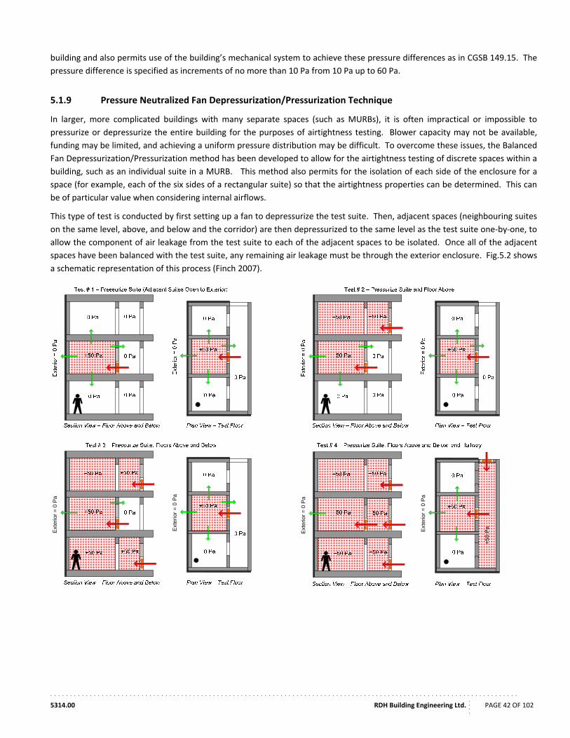
. . . . . . . . . . . . . . . . . . . . . . . . . . . . . . . . . . . . . . . . . . . . . . . . . . . . . . . . . . . . . . . . . . . . . . . . . . . . . . . . . . . . . . . . . . . . . . . . . . . . . . . . . . . . . . . . . . . . . .
5314.00 RDH Building Engineering Ltd.
....
PAGE 42 OF 102
building and also permits use of the building’s mechanical system to achieve these pressure differences as in CGSB 149.15. The
pressure difference is specified as increments of no more than 10 Pa from 10 Pa up to 60 Pa.
5.1.9 Pressure Neutralized Fan Depressurization/Pressurization Technique
In larger, more complicated buildings with many separate spaces (such as MURBs), it is often impractical or impossible to
pressurize or depressurize the entire building for the purposes of airtightness testing. Blower capacity may not be available,
funding may be limited, and achieving a uniform pressure distribution may be difficult. To overcome these issues, the Balanced
Fan Depressurization/Pressurization method has been developed to allow for the airtightness testing of discrete spaces within a
building, such as an individual suite in a MURB. This method also permits for the isolation of each side of the enclosure for a
space (for example, each of the six sides of a rectangular suite) so that the airtightness properties can be determined. This can
be of particular value when considering internal airflows.
This type of test is conducted by first setting up a fan to depressurize the test suite. Then, adjacent spaces (neighbouring suites
on the same level, above, and below and the corridor) are then depressurized to the same level as the test suite one‐by‐one, to
allow the component of air leakage from the test suite to each of the adjacent spaces to be isolated. Once all of the adjacent
spaces have been balanced with the test suite, any remaining air leakage must be through the exterior enclosure. Fig.5.2 shows
a schematic representation of this process (Finch 2007).
Ext
erio
r =
0 P
a
Ext
erio
r =
0 P
a
Ext
erio
r =
0 P
a
+5
0 P
aExt
erio
r =
0 P
a
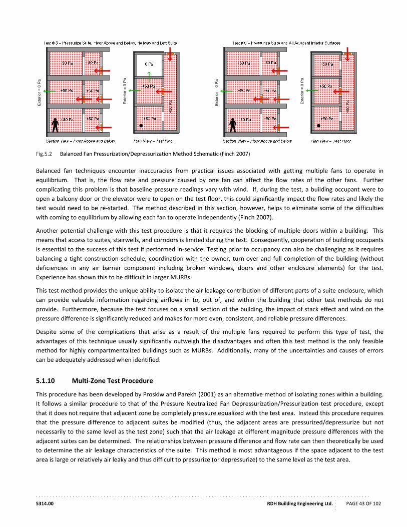
. . . . . . . . . . . . . . . . . . . . . . . . . . . . . . . . . . . . . . . . . . . . . . . . . . . . . . . . . . . . . . . . . . . . . . . . . . . . . . . . . . . . . . . . . . . . . . . . . . . . . . . . . . . . . . . . . . . . . .
5314.00 RDH Building Engineering Ltd.
....
PAGE 43 OF 102
Fig.5.2 Balanced Fan Pressurization/Depressurization Method Schematic (Finch 2007)
Balanced fan techniques encounter inaccuracies from practical issues associated with getting multiple fans to operate in
equilibrium. That is, the flow rate and pressure caused by one fan can affect the flow rates of the other fans. Further
complicating this problem is that baseline pressure readings vary with wind. If, during the test, a building occupant were to
open a balcony door or the elevator were to open on the test floor, this could significantly impact the flow rates and likely the
test would need to be re‐started. The method described in this section, however, helps to eliminate some of the difficulties
with coming to equilibrium by allowing each fan to operate independently (Finch 2007).
Another potential challenge with this test procedure is that it requires the blocking of multiple doors within a building. This
means that access to suites, stairwells, and corridors is limited during the test. Consequently, cooperation of building occupants
is essential to the success of this test if performed in‐service. Testing prior to occupancy can also be challenging as it requires
balancing a tight construction schedule, coordination with the owner, turn‐over and full completion of the building (without
deficiencies in any air barrier component including broken windows, doors and other enclosure elements) for the test.
Experience has shown this to be difficult in larger MURBs.
This test method provides the unique ability to isolate the air leakage contribution of different parts of a suite enclosure, which
can provide valuable information regarding airflows in to, out of, and within the building that other test methods do not
provide. Furthermore, because the test focuses on a small section of the building, the impact of stack effect and wind on the
pressure difference is significantly reduced and makes for more even, consistent, and reliable pressure differences.
Despite some of the complications that arise as a result of the multiple fans required to perform this type of test, the
advantages of this technique usually significantly outweigh the disadvantages and often this test method is the only feasible
method for highly compartmentalized buildings such as MURBs. Additionally, many of the uncertainties and causes of errors
can be adequately addressed when identified.
5.1.10 Multi‐Zone Test Procedure
This procedure has been developed by Proskiw and Parekh (2001) as an alternative method of isolating zones within a building.
It follows a similar procedure to that of the Pressure Neutralized Fan Depressurization/Pressurization test procedure, except
that it does not require that adjacent zone be completely pressure equalized with the test area. Instead this procedure requires
that the pressure difference to adjacent suites be modified (thus, the adjacent areas are pressurized/depressurize but not
necessarily to the same level as the test zone) such that the air leakage at different magnitude pressure differences with the
adjacent suites can be determined. The relationships between pressure difference and flow rate can then theoretically be used
to determine the air leakage characteristics of the suite. This method is most advantageous if the space adjacent to the test
area is large or relatively air leaky and thus difficult to pressurize (or depressurize) to the same level as the test area.
Ext
erio
r =
0 P
a
+50
PaExt
erio
r =
0 P
a
Ext
erio
r =
0 P
a
+50
PaExt
erio
r =
0 P
a
. . . . . . . . . . . . . . . . . . . . . . . . . . . . . . . . . . . . . . . . . . . . . . . . . . . . . . . . . . . . . . . . . . . . . . . . . . . . . . . . . . . . . . . . . . . . . . . . . . . . . . . . . . . . . . . . . . . . . .
5314.00 RDH Building Engineering Ltd.
....
PAGE 44 OF 102
5.1.11 ATTMA Technical Standard L1 ‐ 2010
British Airtightness Testing and Measurement Association (ATTMA) Technical Standard L1: Measuring Air Permeability of
Building Enclosures (Dwellings) is a standard developed primarily for use with detached residential buildings and is similar in
principle to CGSB 149.10. It requires a minimum of 7 flow rate measurements, taken at sequential pressure differences in no
more than 10 Pa increments, starting at a minimum pressure difference of at least 25 Pa. The standard allows for either
pressurization or depressurization of the building.
5.1.12 US Army Corps of Engineers
The US Army Corps of Engineers (USACE) has developed an airtightness testing protocol in conjunction with the Air Barrier
Association of America (ABAA) as part of their program to meet energy saving targets. It is based on ASTM E 779 but provides
some modifications, in particular to accommodate the increased pressure biases that can occur in high‐rise buildings as a result
of increased wind exposure and stack effect. The primary change made to this standard is that it specifies testing at a higher
pressure difference of 25 Pa to 75 Pa (with an allowance for 85 Pa) with at least 10 points in this range. Also, testing according
to this procedure must be performed in both pressurized and depressurized states to better account for any bias that may exist.
This standard provides an exception for the testing of larger buildings that require greater 200,000 cfm (94,000 L/s) of airflow to
create the required 75 Pa pressure difference. It permits these buildings to be tested in either the pressurized or depressurized
state only (rather than both) as the equipment required to achieve this flow may not be capable of both pressurizing and
depressurizing.
5.1.13 Other Procedures
Other testing procedures exist but are not in wide scale use. In many cases, these alternative procedures are modifications of
the procedures discussed above, are intended primarily for research grade airtightness testing, and may not be suitable for
widespread industry adoption without further development. For informational purposes, some of the other techniques are
listed below.
Nylund Technique
This test method is based on the idea that internal airflows between spaces can be determined by measuring the pressured field within the zones adjacent to the test zone that is being pressurized/depressurized. This method, however, assumes that the airtightness of every zone is the same and that the interior air leakage between spaces is much less than the leakage to the exterior, that is, the exterior enclosure air barrier is much leakier than interior separators within the building.
DePani & Fazio Technique
This method is designed such that airtightness characteristics of a single suite can be determined with only one fan by first pressurizing the test suite, and then each of the neighbouring suites one at a time. Using linear algebra, the flow coefficients and flow exponents for each component of the building can be determined. This technique was developed for a three unit building; therefore, it may have some limitations for applications in buildings with more units. (DePani and Fazio 2001)
AC Pressurization
All of the other techniques to this point are considered DC pressurization, which rely on creating steady‐state pressure differences to determine airflow rates and thus building airtightness characteristics. AC pressurization instead creates periodic pressure differences across the building enclosure and then uses the magnitude of the pressure difference and the time over which it changes to determine air leakage properties. (Colliver and Murphy 1992) This technique is somewhat similar in concept to the Lstiburek Technique discussed below.
Lstiburek Technique
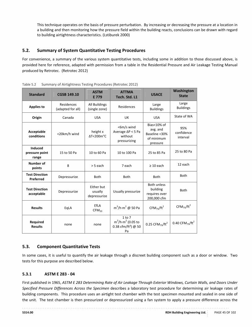
. . . . . . . . . . . . . . . . . . . . . . . . . . . . . . . . . . . . . . . . . . . . . . . . . . . . . . . . . . . . . . . . . . . . . . . . . . . . . . . . . . . . . . . . . . . . . . . . . . . . . . . . . . . . . . . . . . . . . .
5314.00 RDH Building Engineering Ltd.
....
PAGE 45 OF 102
This technique operates on the basis of pressure perturbation. By increasing or decreasing the pressure at a location in a building and then monitoring how the pressure field within the building reacts, conclusions can be drawn with regard to building airtightness characteristics. (Lstiburek 2000)
5.2. Summary of System Quantitative Testing Procedures
For convenience, a summary of the various system quantitative tests, including some in addition to those discussed above, is
provided here for reference, adapted with permission from a table in the Residential Pressure and Air Leakage Testing Manual
produced by Retrotec. (Retrotec 2012)
Table 5.2 Summary of Airtightness Testing Procedures (Retrotec 2012)
Standard CGSB 149.10 ASTM E 779
ATTMA Tech. Std. L1
USACE Washington
State
Applies to Residences
(adapted for all) All Buildings (single zone)
Residences Large
Buildings
Large Buildings
Origin Canada USA UK USA State of WA
Acceptable conditions
<20km/h wind height x
ΔT<200m°C
<6m/s wind Average ΔP < 5 Pa
without pressurizing
Bias<10% of avg. and
Baseline <30% of minimum pressure
95% confidence interval
Induced pressure point
range 15 to 50 Pa 10 to 60 Pa 10 to 100 Pa 25 to 85 Pa 25 to 80 Pa
Number of points
8 > 5 each 7 each ≥ 10 each 12 each
Test Direction Preferred
Depressurize Both Both Both Both
Test Direction acceptable Depressurize
Either but usually
depressurize Usually pressurize
Both unless building
requires over 200,000 cfm
Both
Results EqLA EfLA CFM50
m3/h∙m2 @ 50 Pa CFM75/ft
2 CFM75/ft2
Required Results
none none
1 to 7 m3/h∙m2 (0.05 to 0.38 cfm/ft²) @ 50
Pa
0.25 CFM75/ft2 0.40 CFM75/ft
2
5.3. Component Quantitative Tests
In some cases, it is useful to quantify the air leakage through a discreet building component such as a door or window. Two
tests for this purpose are described below.
5.3.1 ASTM E 283 ‐ 04
First published in 1965, ASTM E 283 Determining Rate of Air Leakage Through Exterior Windows, Curtain Walls, and Doors Under
Specified Pressure Differences Across the Specimen describes a laboratory test procedure for determining air leakage rates of
building components. This procedure uses an airtight test chamber with the test specimen mounted and sealed in one side of
the unit. The test chamber is then pressurized or depressurized using a fan system to apply a pressure difference across the
. . . . . . . . . . . . . . . . . . . . . . . . . . . . . . . . . . . . . . . . . . . . . . . . . . . . . . . . . . . . . . . . . . . . . . . . . . . . . . . . . . . . . . . . . . . . . . . . . . . . . . . . . . . . . . . . . . . . . .
5314.00 RDH Building Engineering Ltd.
....
PAGE 46 OF 102
specimen. The fan equipment should be such that a flow rate, and thus an air leakage rate, can be determined. To achieve
accurate results with this standard, it is important that the specimen is well sealed into the test chamber and that the test
chamber itself is entirely airtight. As this is a laboratory test, it indicates the airtightness of the specimen only, and does provide
any information with regard to potential air leakage due to installation practices in as‐built conditions.
5.3.2 ASTM E 783 ‐02
ASTM E 783 Standard Test Method for Field Measurement of Air Leakage Through Installed Exterior Windows and Doors is
essentially the field test version of ASTM E 283. “The experimental set‐up is basically the same as E 283 with the major
difference being that a special test chamber has to be constructed and attached over the test specimen. Under normal field
conditions, a single test chamber can generally be re‐used two or three times, after which it normally has to be replaced.
Generally, the biggest challenges encountered using E 783 are affixing the chamber over the specimen so as to adequately limit
extraneous leakage and then accurately quantifying the extraneous leakage that remains. The test procedure, analysis method
and methods of reporting results are the same as E 283. It can also be adapted to permit calculation of C and n, and used to test
other types of building components.” (Proskiw and Phillips, Air Leakage Characteristics, Test Methods, and Specifications for
Large Buildings 2001) This test provides a measurement more indicative of in‐service performance than does ASTM E 283 as it
accounts for as‐built conditions.
5.4. Qualitative Tests
While quantitative testing is preferable to obtain results for comparison, benchmarking, and the achievement of set targets,
qualitative tests can also be a very useful tool. Qualitative tests are typically used in forensic investigations of air leakage to
locate high leakage areas and gain an understanding of flow directions and magnitudes.
5.4.1 ASTM E 1186 – 03
ASTM E 1186‐03 Standard Practices for Air Leakage Site Detection in Building Envelopes and Air Barrier Systems describes a
variety of qualitative testing techniques for locating areas of air leakage, outlined in the following sections.
Infrared Photography
Using either fan equipment or the building’s ventilation equipment, the building can be pressurized or depressurized relative to
the exterior under conditions where there is at least a 5°C temperature difference between the interior and exterior. Once the
building is pressurized (or depressurized), an infrared camera is used to illustrate the temperature of enclosure components. If
the building is pressurized, the building should be viewed from the exterior, and if it is depressurized it should be viewed from
the interior, so that the air leakage locations are visible. The surface temperature of enclosure components will change due to
airflow over it, and this temperature difference will be visible using the infrared camera. Typically, temperature differences due
to air leakage appear as streak or plume like patterns.
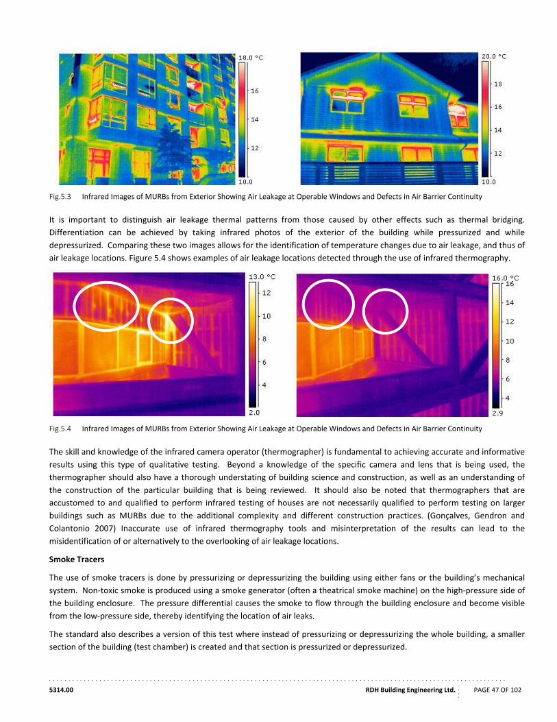
. . . . . . . . . . . . . . . . . . . . . . . . . . . . . . . . . . . . . . . . . . . . . . . . . . . . . . . . . . . . . . . . . . . . . . . . . . . . . . . . . . . . . . . . . . . . . . . . . . . . . . . . . . . . . . . . . . . . . .
5314.00 RDH Building Engineering Ltd.
....
PAGE 47 OF 102
Fig.5.3 Infrared Images of MURBs from Exterior Showing Air Leakage at Operable Windows and Defects in Air Barrier Continuity
It is important to distinguish air leakage thermal patterns from those caused by other effects such as thermal bridging.
Differentiation can be achieved by taking infrared photos of the exterior of the building while pressurized and while
depressurized. Comparing these two images allows for the identification of temperature changes due to air leakage, and thus of
air leakage locations. Figure 5.4 shows examples of air leakage locations detected through the use of infrared thermography.
Fig.5.4 Infrared Images of MURBs from Exterior Showing Air Leakage at Operable Windows and Defects in Air Barrier Continuity
The skill and knowledge of the infrared camera operator (thermographer) is fundamental to achieving accurate and informative
results using this type of qualitative testing. Beyond a knowledge of the specific camera and lens that is being used, the
thermographer should also have a thorough understating of building science and construction, as well as an understanding of
the construction of the particular building that is being reviewed. It should also be noted that thermographers that are
accustomed to and qualified to perform infrared testing of houses are not necessarily qualified to perform testing on larger
buildings such as MURBs due to the additional complexity and different construction practices. (Gonçalves, Gendron and
Colantonio 2007) Inaccurate use of infrared thermography tools and misinterpretation of the results can lead to the
misidentification of or alternatively to the overlooking of air leakage locations.
Smoke Tracers
The use of smoke tracers is done by pressurizing or depressurizing the building using either fans or the building’s mechanical
system. Non‐toxic smoke is produced using a smoke generator (often a theatrical smoke machine) on the high‐pressure side of
the building enclosure. The pressure differential causes the smoke to flow through the building enclosure and become visible
from the low‐pressure side, thereby identifying the location of air leaks.
The standard also describes a version of this test where instead of pressurizing or depressurizing the whole building, a smaller
section of the building (test chamber) is created and that section is pressurized or depressurized.
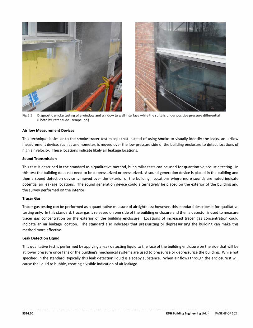
. . . . . . . . . . . . . . . . . . . . . . . . . . . . . . . . . . . . . . . . . . . . . . . . . . . . . . . . . . . . . . . . . . . . . . . . . . . . . . . . . . . . . . . . . . . . . . . . . . . . . . . . . . . . . . . . . . . . . .
5314.00 RDH Building Engineering Ltd.
....
PAGE 48 OF 102
Fig.5.5 Diagnostic smoke testing of a window and window to wall interface while the suite is under positive pressure differential
(Photo by Patenaude Trempe Inc.)
Airflow Measurement Devices
This technique is similar to the smoke tracer test except that instead of using smoke to visually identify the leaks, an airflow
measurement device, such as anemometer, is moved over the low pressure side of the building enclosure to detect locations of
high air velocity. These locations indicate likely air leakage locations.
Sound Transmission
This test is described in the standard as a qualitative method, but similar tests can be used for quantitative acoustic testing. In
this test the building does not need to be depressurized or pressurized. A sound generation device is placed in the building and
then a sound detection device is moved over the exterior of the building. Locations where more sounds are noted indicate
potential air leakage locations. The sound generation device could alternatively be placed on the exterior of the building and
the survey performed on the interior.
Tracer Gas
Tracer gas testing can be performed as a quantitative measure of airtightness; however, this standard describes it for qualitative
testing only. In this standard, tracer gas is released on one side of the building enclosure and then a detector is used to measure
tracer gas concentration on the exterior of the building enclosure. Locations of increased tracer gas concentration could
indicate an air leakage location. The standard also indicates that pressurizing or depressurizing the building can make this
method more effective.
Leak Detection Liquid
This qualitative test is performed by applying a leak detecting liquid to the face of the building enclosure on the side that will be
at lower pressure once fans or the building’s mechanical systems are used to pressurize or depressurize the building. While not
specified in the standard, typically this leak detection liquid is a soapy substance. When air flows through the enclosure it will
cause the liquid to bubble, creating a visible indication of air leakage.
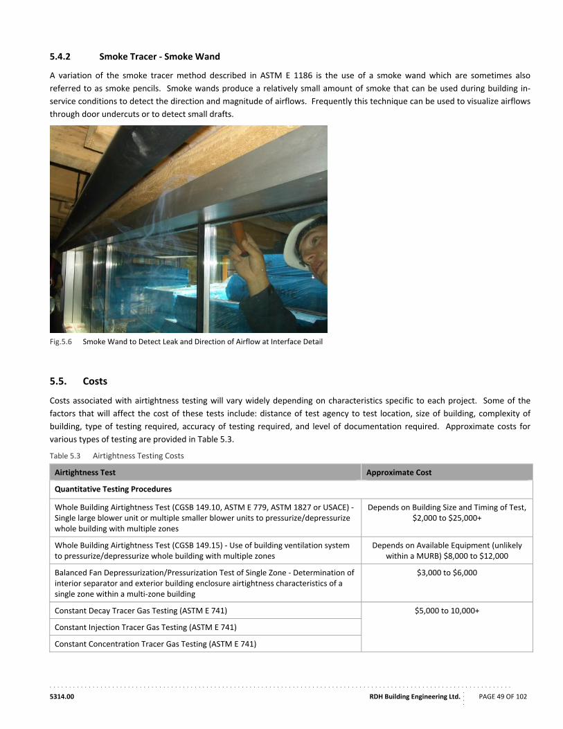
. . . . . . . . . . . . . . . . . . . . . . . . . . . . . . . . . . . . . . . . . . . . . . . . . . . . . . . . . . . . . . . . . . . . . . . . . . . . . . . . . . . . . . . . . . . . . . . . . . . . . . . . . . . . . . . . . . . . . .
5314.00 RDH Building Engineering Ltd.
....
PAGE 49 OF 102
5.4.2 Smoke Tracer ‐ Smoke Wand
A variation of the smoke tracer method described in ASTM E 1186 is the use of a smoke wand which are sometimes also
referred to as smoke pencils. Smoke wands produce a relatively small amount of smoke that can be used during building in‐
service conditions to detect the direction and magnitude of airflows. Frequently this technique can be used to visualize airflows
through door undercuts or to detect small drafts.
Fig.5.6 Smoke Wand to Detect Leak and Direction of Airflow at Interface Detail
5.5. Costs
Costs associated with airtightness testing will vary widely depending on characteristics specific to each project. Some of the
factors that will affect the cost of these tests include: distance of test agency to test location, size of building, complexity of
building, type of testing required, accuracy of testing required, and level of documentation required. Approximate costs for
various types of testing are provided in Table 5.3.
Table 5.3 Airtightness Testing Costs
Airtightness Test Approximate Cost
Quantitative Testing Procedures
Whole Building Airtightness Test (CGSB 149.10, ASTM E 779, ASTM 1827 or USACE) ‐ Single large blower unit or multiple smaller blower units to pressurize/depressurize whole building with multiple zones
Depends on Building Size and Timing of Test, $2,000 to $25,000+
Whole Building Airtightness Test (CGSB 149.15) ‐ Use of building ventilation system to pressurize/depressurize whole building with multiple zones
Depends on Available Equipment (unlikely within a MURB) $8,000 to $12,000
Balanced Fan Depressurization/Pressurization Test of Single Zone ‐ Determination of interior separator and exterior building enclosure airtightness characteristics of a single zone within a multi‐zone building
$3,000 to $6,000
Constant Decay Tracer Gas Testing (ASTM E 741) $5,000 to 10,000+
Constant Injection Tracer Gas Testing (ASTM E 741)
Constant Concentration Tracer Gas Testing (ASTM E 741)
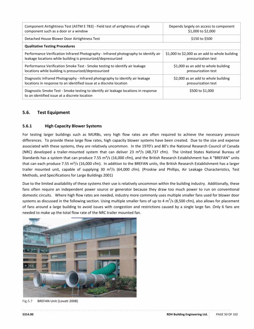
. . . . . . . . . . . . . . . . . . . . . . . . . . . . . . . . . . . . . . . . . . . . . . . . . . . . . . . . . . . . . . . . . . . . . . . . . . . . . . . . . . . . . . . . . . . . . . . . . . . . . . . . . . . . . . . . . . . . . .
5314.00 RDH Building Engineering Ltd.
....
PAGE 50 OF 102
Component Airtightness Test (ASTM E 783) ‐ Field test of airtightness of single component such as a door or a window
Depends largely on access to component $1,000 to $2,000
Detached House Blower Door Airtightness Test $150 to $500
Qualitative Testing Procedures
Performance Verification Infrared Photography ‐ Infrared photography to identify air leakage locations while building is pressurized/depressurized
$1,000 to $2,000 as an add to whole building pressurization test
Performance Verification Smoke Test ‐ Smoke testing to identify air leakage locations while building is pressurized/depressurized
$1,000 as an add to whole building pressurization test
Diagnostic Infrared Photography ‐ Infrared photography to identify air leakage locations in response to an identified issue at a discrete location
$2,000 as an add to whole building pressurization test
Diagnostic Smoke Test ‐ Smoke testing to identify air leakage locations in response to an identified issue at a discrete location
$500 to $1,000
5.6. Test Equipment
5.6.1 High Capacity Blower Systems
For testing larger buildings such as MURBs, very high flow rates are often required to achieve the necessary pressure
differences. To provide these large flow rates, high capacity blower systems have been created. Due to the size and expense
associated with these systems, they are relatively uncommon. In the 1970’s and 80’s the National Research Council of Canada
(NRC) developed a trailer‐mounted system that can deliver 23 m³/s (48,737 cfm). The United States National Bureau of
Standards has a system that can produce 7.55 m³/s (16,000 cfm), and the British Research Establishment has 4 “BREFAN” units
that can each produce 7.55 m³/s (16,000 cfm). In addition to the BREFAN units, the British Research Establishment has a larger
trailer mounted unit, capable of supplying 30 m³/s (64,000 cfm). (Proskiw and Phillips, Air Leakage Characteristics, Test
Methods, and Specifications for Large Buildings 2001)
Due to the limited availability of these systems their use is relatively uncommon within the building industry. Additionally, these
fans often require an independent power source or generator because they draw too much power to run on conventional
domestic circuits. Where high flow rates are needed, industry more commonly uses multiple smaller fans used for blower door
systems as discussed in the following section. Using multiple smaller fans of up to 4 m3/s (8,500 cfm), also allows for placement
of fans around a large building to avoid issues with congestion and restrictions caused by a single large fan. Only 6 fans are
needed to make up the total flow rate of the NRC trailer mounted fan.
Fig.5.7 BREFAN Unit (Lovatt 2008)
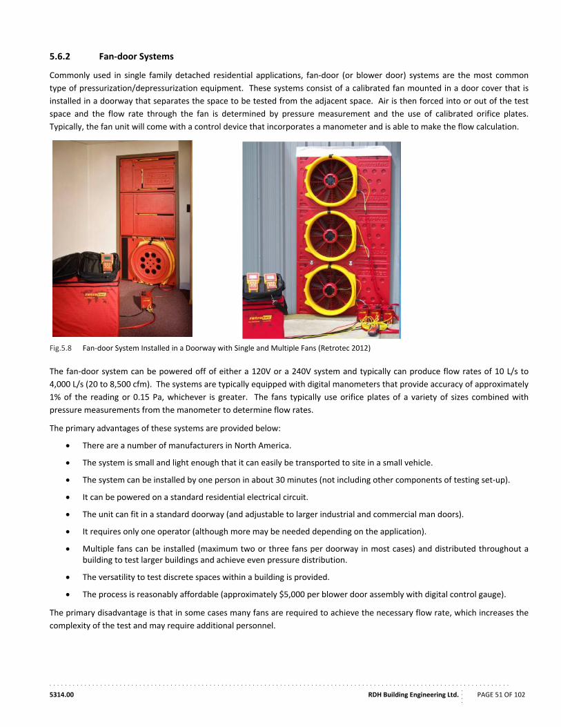
. . . . . . . . . . . . . . . . . . . . . . . . . . . . . . . . . . . . . . . . . . . . . . . . . . . . . . . . . . . . . . . . . . . . . . . . . . . . . . . . . . . . . . . . . . . . . . . . . . . . . . . . . . . . . . . . . . . . . .
5314.00 RDH Building Engineering Ltd.
....
PAGE 51 OF 102
5.6.2 Fan‐door Systems
Commonly used in single family detached residential applications, fan‐door (or blower door) systems are the most common
type of pressurization/depressurization equipment. These systems consist of a calibrated fan mounted in a door cover that is
installed in a doorway that separates the space to be tested from the adjacent space. Air is then forced into or out of the test
space and the flow rate through the fan is determined by pressure measurement and the use of calibrated orifice plates.
Typically, the fan unit will come with a control device that incorporates a manometer and is able to make the flow calculation.
Fig.5.8 Fan‐door System Installed in a Doorway with Single and Multiple Fans (Retrotec 2012)
The fan‐door system can be powered off of either a 120V or a 240V system and typically can produce flow rates of 10 L/s to
4,000 L/s (20 to 8,500 cfm). The systems are typically equipped with digital manometers that provide accuracy of approximately
1% of the reading or 0.15 Pa, whichever is greater. The fans typically use orifice plates of a variety of sizes combined with
pressure measurements from the manometer to determine flow rates.
The primary advantages of these systems are provided below:
There are a number of manufacturers in North America.
The system is small and light enough that it can easily be transported to site in a small vehicle.
The system can be installed by one person in about 30 minutes (not including other components of testing set‐up).
It can be powered on a standard residential electrical circuit.
The unit can fit in a standard doorway (and adjustable to larger industrial and commercial man doors).
It requires only one operator (although more may be needed depending on the application).
Multiple fans can be installed (maximum two or three fans per doorway in most cases) and distributed throughout a building to test larger buildings and achieve even pressure distribution.
The versatility to test discrete spaces within a building is provided.
The process is reasonably affordable (approximately $5,000 per blower door assembly with digital control gauge).
The primary disadvantage is that in some cases many fans are required to achieve the necessary flow rate, which increases the
complexity of the test and may require additional personnel.
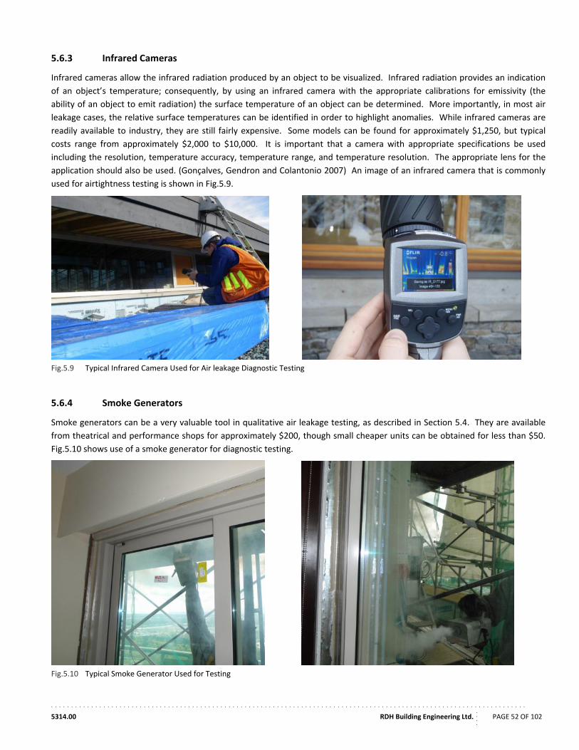
. . . . . . . . . . . . . . . . . . . . . . . . . . . . . . . . . . . . . . . . . . . . . . . . . . . . . . . . . . . . . . . . . . . . . . . . . . . . . . . . . . . . . . . . . . . . . . . . . . . . . . . . . . . . . . . . . . . . . .
5314.00 RDH Building Engineering Ltd.
....
PAGE 52 OF 102
5.6.3 Infrared Cameras
Infrared cameras allow the infrared radiation produced by an object to be visualized. Infrared radiation provides an indication
of an object’s temperature; consequently, by using an infrared camera with the appropriate calibrations for emissivity (the
ability of an object to emit radiation) the surface temperature of an object can be determined. More importantly, in most air
leakage cases, the relative surface temperatures can be identified in order to highlight anomalies. While infrared cameras are
readily available to industry, they are still fairly expensive. Some models can be found for approximately $1,250, but typical
costs range from approximately $2,000 to $10,000. It is important that a camera with appropriate specifications be used
including the resolution, temperature accuracy, temperature range, and temperature resolution. The appropriate lens for the
application should also be used. (Gonçalves, Gendron and Colantonio 2007) An image of an infrared camera that is commonly
used for airtightness testing is shown in Fig.5.9.
Fig.5.9 Typical Infrared Camera Used for Air leakage Diagnostic Testing
5.6.4 Smoke Generators
Smoke generators can be a very valuable tool in qualitative air leakage testing, as described in Section 5.4. They are available
from theatrical and performance shops for approximately $200, though small cheaper units can be obtained for less than $50.
Fig.5.10 shows use of a smoke generator for diagnostic testing.
Fig.5.10 Typical Smoke Generator Used for Testing
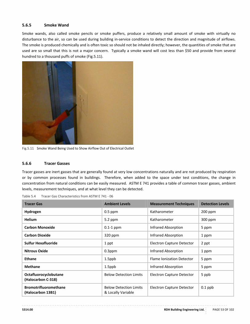
. . . . . . . . . . . . . . . . . . . . . . . . . . . . . . . . . . . . . . . . . . . . . . . . . . . . . . . . . . . . . . . . . . . . . . . . . . . . . . . . . . . . . . . . . . . . . . . . . . . . . . . . . . . . . . . . . . . . . .
5314.00 RDH Building Engineering Ltd.
....
PAGE 53 OF 102
5.6.5 Smoke Wand
Smoke wands, also called smoke pencils or smoke puffers, produce a relatively small amount of smoke with virtually no
disturbance to the air, so can be used during building in‐service conditions to detect the direction and magnitude of airflows.
The smoke is produced chemically and is often toxic so should not be inhaled directly; however, the quantities of smoke that are
used are so small that this is not a major concern. Typically a smoke wand will cost less than $50 and provide from several
hundred to a thousand puffs of smoke (Fig.5.11).
Fig.5.11 Smoke Wand Being Used to Show Airflow Out of Electrical Outlet
5.6.6 Tracer Gasses
Tracer gasses are inert gasses that are generally found at very low concentrations naturally and are not produced by respiration
or by common processes found in buildings. Therefore, when added to the space under test conditions, the change in
concentration from natural conditions can be easily measured. ASTM E 741 provides a table of common tracer gasses, ambient
levels, measurement techniques, and at what level they can be detected.
Table 5.4 Tracer Gas Characteristics from ASTM E 741 ‐ 06
Tracer Gas Ambient Levels Measurement Techniques Detection Levels
Hydrogen 0.5 ppm Katharometer 200 ppm
Helium 5.2 ppm Katharometer 300 ppm
Carbon Monoxide 0.1‐1 ppm Infrared Absorption 5 ppm
Carbon Dioxide 320 ppm Infrared Absorption 1 ppm
Sulfur Hexafluoride 1 ppt Electron Capture Detector 2 ppt
Nitrous Oxide 0.3ppm Infrared Absorption 1 ppm
Ethane 1.5ppb Flame Ionization Detector 5 ppm
Methane 1.5ppb Infrared Absorption 5 ppm
Octafluorocyclobutane (Halocarbon C‐318)
Below Detection Limits Electron Capture Detector 5 ppb
Bromotrifluoromethane (Halocarbon 13B1)
Below Detection Limits & Locally Variable
Electron Capture Detector 0.1 ppb
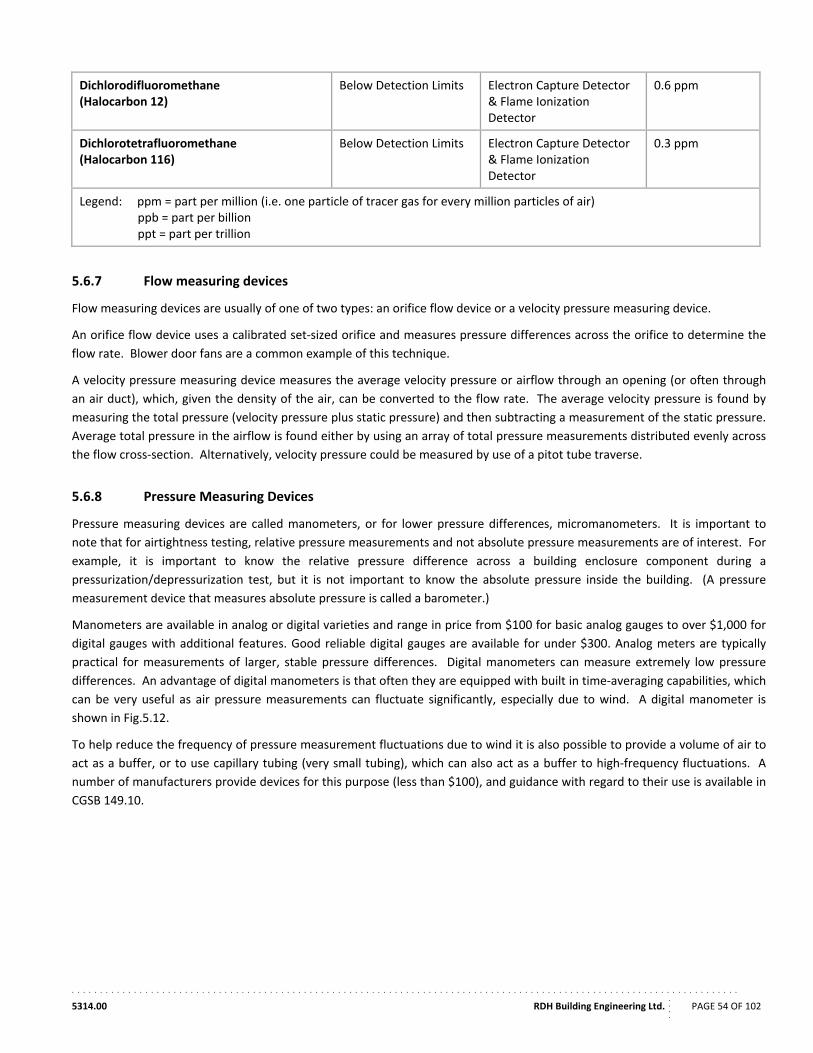
. . . . . . . . . . . . . . . . . . . . . . . . . . . . . . . . . . . . . . . . . . . . . . . . . . . . . . . . . . . . . . . . . . . . . . . . . . . . . . . . . . . . . . . . . . . . . . . . . . . . . . . . . . . . . . . . . . . . . .
5314.00 RDH Building Engineering Ltd.
....
PAGE 54 OF 102
Dichlorodifluoromethane (Halocarbon 12)
Below Detection Limits Electron Capture Detector & Flame Ionization Detector
0.6 ppm
Dichlorotetrafluoromethane (Halocarbon 116)
Below Detection Limits Electron Capture Detector & Flame Ionization Detector
0.3 ppm
Legend: ppm = part per million (i.e. one particle of tracer gas for every million particles of air) ppb = part per billion ppt = part per trillion
5.6.7 Flow measuring devices
Flow measuring devices are usually of one of two types: an orifice flow device or a velocity pressure measuring device.
An orifice flow device uses a calibrated set‐sized orifice and measures pressure differences across the orifice to determine the
flow rate. Blower door fans are a common example of this technique.
A velocity pressure measuring device measures the average velocity pressure or airflow through an opening (or often through
an air duct), which, given the density of the air, can be converted to the flow rate. The average velocity pressure is found by
measuring the total pressure (velocity pressure plus static pressure) and then subtracting a measurement of the static pressure.
Average total pressure in the airflow is found either by using an array of total pressure measurements distributed evenly across
the flow cross‐section. Alternatively, velocity pressure could be measured by use of a pitot tube traverse.
5.6.8 Pressure Measuring Devices
Pressure measuring devices are called manometers, or for lower pressure differences, micromanometers. It is important to
note that for airtightness testing, relative pressure measurements and not absolute pressure measurements are of interest. For
example, it is important to know the relative pressure difference across a building enclosure component during a
pressurization/depressurization test, but it is not important to know the absolute pressure inside the building. (A pressure
measurement device that measures absolute pressure is called a barometer.)
Manometers are available in analog or digital varieties and range in price from $100 for basic analog gauges to over $1,000 for
digital gauges with additional features. Good reliable digital gauges are available for under $300. Analog meters are typically
practical for measurements of larger, stable pressure differences. Digital manometers can measure extremely low pressure
differences. An advantage of digital manometers is that often they are equipped with built in time‐averaging capabilities, which
can be very useful as air pressure measurements can fluctuate significantly, especially due to wind. A digital manometer is
shown in Fig.5.12.
To help reduce the frequency of pressure measurement fluctuations due to wind it is also possible to provide a volume of air to
act as a buffer, or to use capillary tubing (very small tubing), which can also act as a buffer to high‐frequency fluctuations. A
number of manufacturers provide devices for this purpose (less than $100), and guidance with regard to their use is available in
CGSB 149.10.
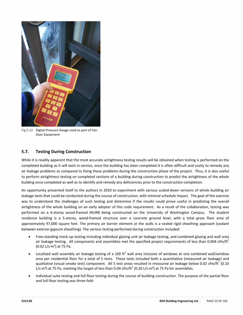
. . . . . . . . . . . . . . . . . . . . . . . . . . . . . . . . . . . . . . . . . . . . . . . . . . . . . . . . . . . . . . . . . . . . . . . . . . . . . . . . . . . . . . . . . . . . . . . . . . . . . . . . . . . . . . . . . . . . . .
5314.00 RDH Building Engineering Ltd.
....
PAGE 55 OF 102
Fig.5.12 Digital Pressure Gauge used as part of Fan‐Door Equipment
5.7. Testing During Construction
While it is readily apparent that the most accurate airtightness testing results will be obtained when testing is performed on the
completed building as it will exist in‐service, once the building has been completed it is often difficult and costly to remedy any
air leakage problems as compared to fixing these problems during the construction phase of the project. Thus, it is also useful
to perform airtightness testing on completed sections of a building during construction to predict the airtightness of the whole
building once completed as well as to identify and remedy any deficiencies prior to the construction completion.
An opportunity presented itself to the authors in 2010 to experiment with various scaled‐down versions of whole building air
leakage tests that could be conducted during the course of construction, with minimal schedule impact. The goal of the exercise
was to understand the challenges of such testing and determine if the results could prove useful in predicting the overall
airtightness of the whole building on an early adopter of this code requirement. As a result of the collaboration, testing was
performed on a 6‐storey wood‐framed MURB being constructed on the University of Washington Campus. The student
residence building is a 5‐storey, wood‐framed structure over a concrete ground level, with a total gross floor area of
approximately 97,000 square feet. The primary air barrier element at the walls is a sealed rigid sheathing approach (sealant
between exterior gypsum sheathing). The various testing performed during construction included:
Free‐standing mock‐up testing including individual glazing unit air leakage testing, and combined glazing and wall area air leakage testing. All components and assemblies met the specified project requirements of less than 0.004 cfm/ft2 (0.02 L/s∙m²) at 75 Pa.
Localized wall assembly air leakage testing of a 100 ft2 wall area inclusive of windows at one combined wall/window area per residential floor for a total of 5 tests. These tests included both a quantitative (measured air leakage) and qualitative (visual smoke test) component. All 5 test areas resulted in measured air leakage below 0.02 cfm/ft2 (0.10 L/s∙m²) at 75 Pa, meeting the target of less than 0.04 cfm/ft2 (0.20 L/s∙m²) at 75 Pa for assemblies.
Individual suite testing and full floor testing during the course of building construction. The purpose of the partial floor and full floor testing was three‐fold:
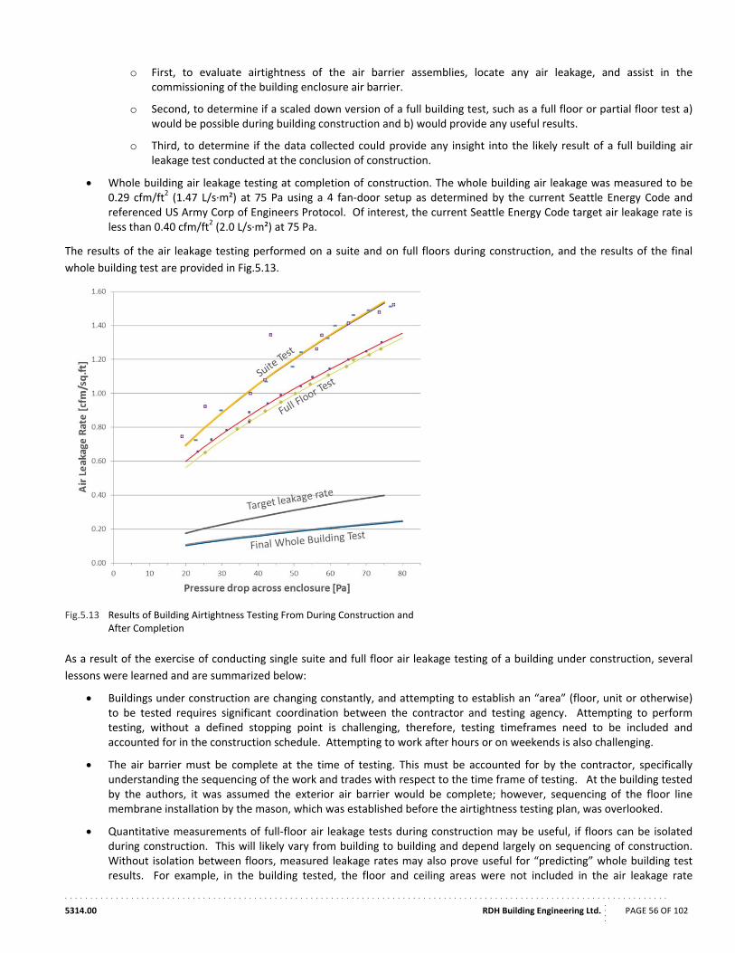
. . . . . . . . . . . . . . . . . . . . . . . . . . . . . . . . . . . . . . . . . . . . . . . . . . . . . . . . . . . . . . . . . . . . . . . . . . . . . . . . . . . . . . . . . . . . . . . . . . . . . . . . . . . . . . . . . . . . . .
5314.00 RDH Building Engineering Ltd.
....
PAGE 56 OF 102
o First, to evaluate airtightness of the air barrier assemblies, locate any air leakage, and assist in the commissioning of the building enclosure air barrier.
o Second, to determine if a scaled down version of a full building test, such as a full floor or partial floor test a) would be possible during building construction and b) would provide any useful results.
o Third, to determine if the data collected could provide any insight into the likely result of a full building air leakage test conducted at the conclusion of construction.
Whole building air leakage testing at completion of construction. The whole building air leakage was measured to be 0.29 cfm/ft2 (1.47 L/s∙m²) at 75 Pa using a 4 fan‐door setup as determined by the current Seattle Energy Code and referenced US Army Corp of Engineers Protocol. Of interest, the current Seattle Energy Code target air leakage rate is less than 0.40 cfm/ft2 (2.0 L/s∙m²) at 75 Pa.
The results of the air leakage testing performed on a suite and on full floors during construction, and the results of the final
whole building test are provided in Fig.5.13.
Fig.5.13 Results of Building Airtightness Testing From During Construction and After Completion
As a result of the exercise of conducting single suite and full floor air leakage testing of a building under construction, several
lessons were learned and are summarized below:
Buildings under construction are changing constantly, and attempting to establish an “area” (floor, unit or otherwise) to be tested requires significant coordination between the contractor and testing agency. Attempting to perform testing, without a defined stopping point is challenging, therefore, testing timeframes need to be included and accounted for in the construction schedule. Attempting to work after hours or on weekends is also challenging.
The air barrier must be complete at the time of testing. This must be accounted for by the contractor, specifically understanding the sequencing of the work and trades with respect to the time frame of testing. At the building tested by the authors, it was assumed the exterior air barrier would be complete; however, sequencing of the floor line membrane installation by the mason, which was established before the airtightness testing plan, was overlooked.
Quantitative measurements of full‐floor air leakage tests during construction may be useful, if floors can be isolated during construction. This will likely vary from building to building and depend largely on sequencing of construction. Without isolation between floors, measured leakage rates may also prove useful for “predicting” whole building test results. For example, in the building tested, the floor and ceiling areas were not included in the air leakage rate
. . . . . . . . . . . . . . . . . . . . . . . . . . . . . . . . . . . . . . . . . . . . . . . . . . . . . . . . . . . . . . . . . . . . . . . . . . . . . . . . . . . . . . . . . . . . . . . . . . . . . . . . . . . . . . . . . . . . . .
5314.00 RDH Building Engineering Ltd.
....
PAGE 57 OF 102
calculation. Had these areas been accounted for, the test results would have been more in line with the whole building test results.
Qualitative testing (smoke testing and or thermographic scans) under pressurization and depressurization is a useful tool for immediately identifying air leakage paths that can be quickly remedied by the contractor. This type of testing is more easily achieved during the course of construction because complete isolation/neutralization between floors is not critical.
In summary, while qualitative testing to identify air leakage paths can provide significant value and help to ensure that air
leakage targets are met upon completion of the building, it is difficult to adequately isolate areas of a building that is under
construction so that useful quantitative data can be collected.
In follow‐up to this case‐study, as part of the same MURB development in Seattle, two companion buildings of similar size and
identical assemblies were constructed in 2012 and 2013 by the same builder and design team. Applying the lessons learned
from the testing at the first building, improvements to the air‐barrier details were made to both newer buildings by the builder,
particularly at HVAC equipment and the roof parapet detailing approaches. In all three buildings a sealed sheathing (silicone
sealant between joints of exterior gypsum sheathing) was used as the primary wall air barrier strategy, integrated with the rest
of the building (windows, roof, below grade etc.).
In the 2012 building, whole building airtightness testing performed prior to occupancy was measured using a 4‐fan setup, and
found to be 0.19 cfm/ft2 at 75 Pa (0.96 L/s∙m²), a reduction of 34% from the first building at 0.29 cfm/ft2. In the 2013 building,
whole building airtightness testing was also performed prior to occupancy, and found to be even better at 0.13 cfm/ft2 at 75 Pa
(0.66 L/s∙m²), a reduction of 55% from the first building.
Infrared scans of all three buildings revealed very little leakage at the building enclosure details, with most occurring at double
entry doors (even with weather‐stripping) and HVAC equipment (even where fully bagged/sealed/dampered closed for the
test). These case study buildings demonstrate the potential to construct very airtight MURBs using readily available and cost
effective methods of residential construction. The case studies also demonstrated that the enclosures themselves were very
airtight, with the majority of leaks occurring through HVAC equipment (dampers and connections), highlighting the need for
research into improvements here.
. . . . . . . . . . . . . . . . . . . . . . . . . . . . . . . . . . . . . . . . . . . . . . . . . . . . . . . . . . . . . . . . . . . . . . . . . . . . . . . . . . . . . . . . . . . . . . . . . . . . . . . . . . . . . . . . . . . . . .
5314.00 RDH Building Engineering Ltd.
....
PAGE 58 OF 102
6. Airtightness Regulatory Requirements and Targets
A wide range of airtightness testing requirements and performance targets exist both in Canada and internationally. Some of
these requirements are mandatory, others voluntary, and others are part of third‐party certification programs.
6.1. Canada
6.1.1 National Building Code for Canada (NBCC) and National Energy Code for Buildings (NECB)
Canadian construction codes including the 2010 NBCC (National Building Code of Canada) and 2011 NECB (National Energy Code
for Buildings) contain general air barrier continuity requirements. The 2011 NECB states that “the building envelope shall be
designed and constructed with a continuous air barrier system comprised of air barrier assemblies to control air leakage into
and out of the conditioned space” and that “all opaque building assemblies that act as environmental separators shall include
an air barrier assembly”. Materials used as part of the air barrier systems must be air impermeable (less than 0.02 L/s∙m2 (0.004
cfm/ft2) at 75 Pa, normalized to enclosure area, not floor area), free of holes and cracks, and compatible with adjoining
materials. Prescriptive air‐sealing measures are included to ensure air barrier continuity.
In addition to opaque enclosure assemblies, the airtightness of manufactured fenestration must meet certain testing
requirements as tested to AAMA/WDMA/ASTM/CSA requirements, which range from 0.2 L/s∙m2 (0.04 cfm/ft2) at 75 Pa to 0.5
L/s∙m2 (0.1 cfm/ft2) at 75 Pa, again normalized to enclosure area, not floor area, and air barrier continuity between opaque
assemblies and fenestration must be maintained.
Within Canada there are currently no building or energy code requirements for the measurement or quantitative testing of
whole building airtightness of MURBs.
6.1.2 Leadership in Energy and Environmental Design (LEED) Canada 2009
The LEED green building rating systems as administered in Canada by the Canada Green Building Council is a points system for
evaluating the performance of buildings with respect to environmental targets and has gained significant traction in industry.
This standard, however, does not contain any prescriptive requirement for airtightness for energy consumption or durability
purposes. Instead, LEED’s airtightness requirements are included for containment of indoor pollutants – primarily tobacco
smoke.
One of the requirements of the standard, mandatory to obtain any LEED certification, is that individual suites in a multi‐unit
residential building achieve an Equivalent Normalized Leakage Area (Normalized EqLA) of 1.65 cm²/m² of enclosure when
calculated using the CGSB 149.10 method. In this case, the “enclosure” includes both the exterior enclosure and interior
separating elements. (LEED Canada 2009)
This requirement is the same for new construction, major renovations, and existing buildings.
6.2. United States
6.2.1 ASHRAE Standards 90.1
Section 5.4.3 of ASHRAE Standard 90.1 provides general airtightness requirements for a variety of components of the building
enclosure including doors and windows; however, no guidance is provided on the overall airtightness target of the building
enclosure.
. . . . . . . . . . . . . . . . . . . . . . . . . . . . . . . . . . . . . . . . . . . . . . . . . . . . . . . . . . . . . . . . . . . . . . . . . . . . . . . . . . . . . . . . . . . . . . . . . . . . . . . . . . . . . . . . . . . . . .
5314.00 RDH Building Engineering Ltd.
....
PAGE 59 OF 102
6.2.2 ASHRAE Standard 189.1 – 2011
Compliance with the newest version of ASHRAE Standard 189.1 Standard for the Design of High‐Performance, Green Buildings
provides a variety requirements for airtightness performance of materials used as part of the air barrier, of the air barrier
assemblies, and of the building as a whole. For the building as a whole the standard requires that air leakage be less than 0.40
cfm/ft2 tested at 75 Pa in accordance with ASTM E779.
6.2.3 ASHRAE Handbook of Fundamentals 2009
The ASHRAE Handbook of Fundamentals produced by the American Society of Heating, Refrigeration, and Air‐Conditioning
Engineers covers a wide range of issues relevant to building design. It provides values from a Tamura and Shaw study (Tamura
and Shaw 1976) which proposes that 0.10 cfm/ft2, 0.30 cfm/ft2 and 0.60 cfm/ft2 of enclosure area (0.5 L/s∙m², 1.5 L/s∙m², and
3.0 L/s∙m²) at 75 Pa should be considered tight, average, and leaky values respectively.
6.2.4 Energy Star®
The Energy Star® system is a rating system for building and provides some guidance for airtightness of high‐rise buildings. This
system requires that buildings be tested in accordance with ASTM E 779 or ASTM E 1827 and achieve a target of 0.30 cfm/ft²
(1.5 L/s∙m²) of enclosure area at a 50 Pa pressure differential. (Note that if the ASTM E 1827 standard is followed, only a single
point test is required.) This requirement applies to both the exterior enclosure and interior separation elements. Additionally,
the airtightness target is a requirement for both the prescriptive and performance paths in the Energy Star® system. (Energy
Star 2011)
Energy Star® has extensive requirements related to the sample size of the apartments tested in a multi‐unit residential building.
First, there is a preliminary testing phase in which at least one corner unit and one middle unit are tested as early in the
construction process as possible to provide an early check of design and installation. If the units fail, the air barrier system must
be improved until it meets the prescribed target, and changes noted and applied to subsequent areas of the building. The final
testing phase requires that one in every seven suites be tested to ensure achievement of the airtightness requirement. If the
one tested suite does not pass the test, an additional two suites from the seven must be tested. If either of those two suites
does not meet the requirement, the remaining four suites of the seven must also be tested. During the course of this
procedure, any suite that fails to meet the test must have the deficiencies corrected and be retested until it meets the specified
target. (Energy Star 2011)
6.3. International
6.3.1 International Energy Conservation Code (IECC)
The 2012 IECC has requirements for air barrier assemblies and air leakage control in residential and commercial buildings.
For residential buildings including those less than 3 stories and some small MURBs, Section R402.4 states that “the building
envelope shall be constructed to limit air leakage” and includes performance based requirements for whole building air leakage
testing. A whole house or dwelling unit fan‐door test to meet an air leakage rate of 5 ACH@ 50 Pa or less in climate zones 1‐3
and 3 ACH @ 50 Pa or less in climate zones 4‐8 is required. A map indicating these climate zones in North America is provided
in Fig.6.1. Testing, where required by the code official, is to be performed by an approved third party to inspect all building
enclosure components and verify compliance.
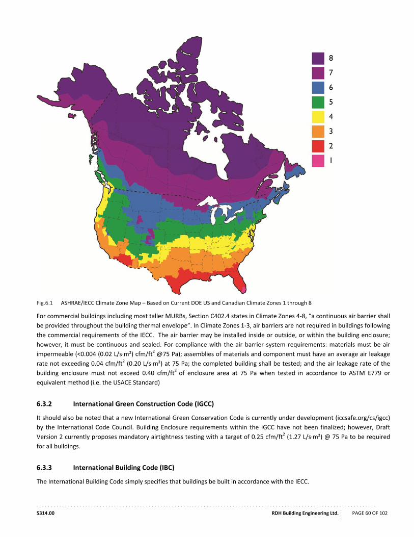
. . . . . . . . . . . . . . . . . . . . . . . . . . . . . . . . . . . . . . . . . . . . . . . . . . . . . . . . . . . . . . . . . . . . . . . . . . . . . . . . . . . . . . . . . . . . . . . . . . . . . . . . . . . . . . . . . . . . . .
5314.00 RDH Building Engineering Ltd.
....
PAGE 60 OF 102
Fig.6.1 ASHRAE/IECC Climate Zone Map – Based on Current DOE US and Canadian Climate Zones 1 through 8
For commercial buildings including most taller MURBs, Section C402.4 states in Climate Zones 4‐8, “a continuous air barrier shall
be provided throughout the building thermal envelope”. In Climate Zones 1‐3, air barriers are not required in buildings following
the commercial requirements of the IECC. The air barrier may be installed inside or outside, or within the building enclosure;
however, it must be continuous and sealed. For compliance with the air barrier system requirements: materials must be air
impermeable (<0.004 (0.02 L/s∙m²) cfm/ft2 @75 Pa); assemblies of materials and component must have an average air leakage
rate not exceeding 0.04 cfm/ft2 (0.20 L/s∙m²) at 75 Pa; the completed building shall be tested; and the air leakage rate of the
building enclosure must not exceed 0.40 cfm/ft2 of enclosure area at 75 Pa when tested in accordance to ASTM E779 or
equivalent method (i.e. the USACE Standard)
6.3.2 International Green Construction Code (IGCC)
It should also be noted that a new International Green Conservation Code is currently under development (iccsafe.org/cs/igcc)
by the International Code Council. Building Enclosure requirements within the IGCC have not been finalized; however, Draft
Version 2 currently proposes mandatory airtightness testing with a target of 0.25 cfm/ft2 (1.27 L/s∙m²) @ 75 Pa to be required
for all buildings.
6.3.3 International Building Code (IBC)
The International Building Code simply specifies that buildings be built in accordance with the IECC.
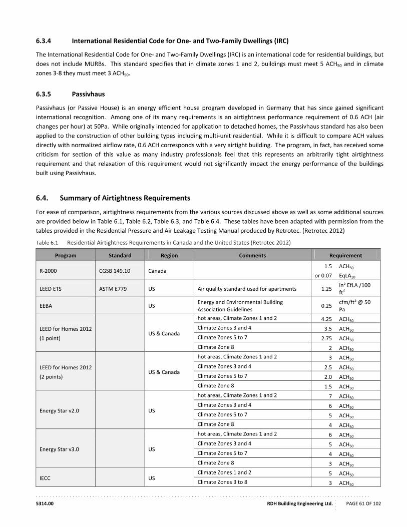
. . . . . . . . . . . . . . . . . . . . . . . . . . . . . . . . . . . . . . . . . . . . . . . . . . . . . . . . . . . . . . . . . . . . . . . . . . . . . . . . . . . . . . . . . . . . . . . . . . . . . . . . . . . . . . . . . . . . . .
5314.00 RDH Building Engineering Ltd.
....
PAGE 61 OF 102
6.3.4 International Residential Code for One‐ and Two‐Family Dwellings (IRC)
The International Residential Code for One‐ and Two‐Family Dwellings (IRC) is an international code for residential buildings, but
does not include MURBs. This standard specifies that in climate zones 1 and 2, buildings must meet 5 ACH50 and in climate
zones 3‐8 they must meet 3 ACH50.
6.3.5 Passivhaus
Passivhaus (or Passive House) is an energy efficient house program developed in Germany that has since gained significant
international recognition. Among one of its many requirements is an airtightness performance requirement of 0.6 ACH (air
changes per hour) at 50Pa. While originally intended for application to detached homes, the Passivhaus standard has also been
applied to the construction of other building types including multi‐unit residential. While it is difficult to compare ACH values
directly with normalized airflow rate, 0.6 ACH corresponds with a very airtight building. The program, in fact, has received some
criticism for section of this value as many industry professionals feel that this represents an arbitrarily tight airtightness
requirement and that relaxation of this requirement would not significantly impact the energy performance of the buildings
built using Passivhaus.
6.4. Summary of Airtightness Requirements
For ease of comparison, airtightness requirements from the various sources discussed above as well as some additional sources
are provided below in Table 6.1, Table 6.2, Table 6.3, and Table 6.4. These tables have been adapted with permission from the
tables provided in the Residential Pressure and Air Leakage Testing Manual produced by Retrotec. (Retrotec 2012)
Table 6.1 Residential Airtightness Requirements in Canada and the United States (Retrotec 2012)
Program Standard Region Comments Requirement
R‐2000 CGSB 149.10 Canada 1.5
or 0.07
ACH50
EqLA10
LEED ETS ASTM E779 US Air quality standard used for apartments 1.25 in² EfLA /100 ft2
EEBA US Energy and Environmental Building Association Guidelines
0.25 cfm/ft² @ 50 Pa
LEED for Homes 2012
(1 point) US & Canada
hot areas, Climate Zones 1 and 2 4.25 ACH50
Climate Zones 3 and 4 3.5 ACH50
Climate Zones 5 to 7 2.75 ACH50
Climate Zone 8 2 ACH50
LEED for Homes 2012
(2 points) US & Canada
hot areas, Climate Zones 1 and 2 3 ACH50
Climate Zones 3 and 4 2.5 ACH50
Climate Zones 5 to 7 2.0 ACH50
Climate Zone 8 1.5 ACH50
Energy Star v2.0 US
hot areas, Climate Zones 1 and 2 7 ACH50
Climate Zones 3 and 4 6 ACH50
Climate Zones 5 to 7 5 ACH50
Climate Zone 8 4 ACH50
Energy Star v3.0 US
hot areas, Climate Zones 1 and 2 6 ACH50
Climate Zones 3 and 4 5 ACH50
Climate Zones 5 to 7 4 ACH50
Climate Zone 8 3 ACH50
IECC US Climate Zones 1 and 2 5 ACH50
Climate Zones 3 to 8 3 ACH50
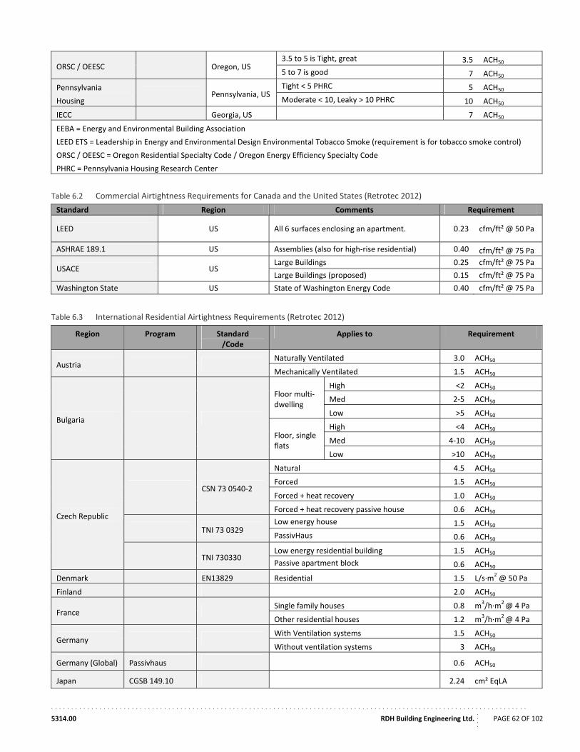
. . . . . . . . . . . . . . . . . . . . . . . . . . . . . . . . . . . . . . . . . . . . . . . . . . . . . . . . . . . . . . . . . . . . . . . . . . . . . . . . . . . . . . . . . . . . . . . . . . . . . . . . . . . . . . . . . . . . . .
5314.00 RDH Building Engineering Ltd.
....
PAGE 62 OF 102
ORSC / OEESC Oregon, US 3.5 to 5 is Tight, great 3.5 ACH50
5 to 7 is good 7 ACH50
Pennsylvania
Housing Pennsylvania, US
Tight < 5 PHRC 5 ACH50
Moderate < 10, Leaky > 10 PHRC 10 ACH50
IECC Georgia, US 7 ACH50
EEBA = Energy and Environmental Building Association
LEED ETS = Leadership in Energy and Environmental Design Environmental Tobacco Smoke (requirement is for tobacco smoke control)
ORSC / OEESC = Oregon Residential Specialty Code / Oregon Energy Efficiency Specialty Code
PHRC = Pennsylvania Housing Research Center
Table 6.2 Commercial Airtightness Requirements for Canada and the United States (Retrotec 2012)
Standard Region Comments Requirement
LEED US All 6 surfaces enclosing an apartment. 0.23 cfm/ft² @ 50 Pa
ASHRAE 189.1 US Assemblies (also for high‐rise residential) 0.40 cfm/ft² @ 75 Pa
USACE US Large Buildings 0.25 cfm/ft² @ 75 Pa
Large Buildings (proposed) 0.15 cfm/ft² @ 75 Pa
Washington State US State of Washington Energy Code 0.40 cfm/ft² @ 75 Pa
Table 6.3 International Residential Airtightness Requirements (Retrotec 2012)
Region Program Standard /Code
Applies to Requirement
Austria Naturally Ventilated 3.0 ACH50
Mechanically Ventilated 1.5 ACH50
Bulgaria
Floor multi‐dwelling
High <2 ACH50
Med 2‐5 ACH50
Low >5 ACH50
Floor, single flats
High <4 ACH50
Med 4‐10 ACH50
Low >10 ACH50
Czech Republic
CSN 73 0540‐2
Natural 4.5 ACH50
Forced 1.5 ACH50
Forced + heat recovery 1.0 ACH50
Forced + heat recovery passive house 0.6 ACH50
TNI 73 0329 Low energy house 1.5 ACH50
PassivHaus 0.6 ACH50
TNI 730330 Low energy residential building 1.5 ACH50
Passive apartment block 0.6 ACH50
Denmark EN13829 Residential 1.5 L/s∙m2 @ 50 Pa
Finland 2.0 ACH50
France Single family houses 0.8 m3/h∙m2 @ 4 Pa
Other residential houses 1.2 m3/h∙m2 @ 4 Pa
Germany With Ventilation systems 1.5 ACH50
Without ventilation systems 3 ACH50
Germany (Global) Passivhaus 0.6 ACH50
Japan CGSB 149.10 2.24 cm² EqLA
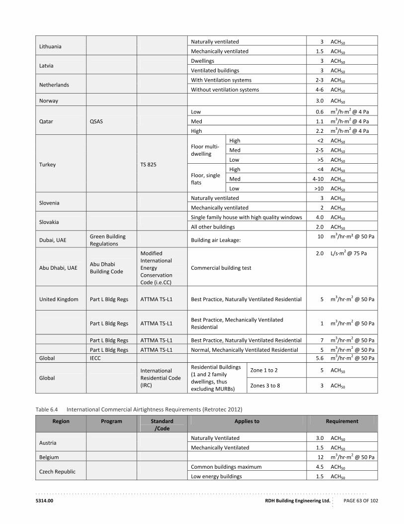
. . . . . . . . . . . . . . . . . . . . . . . . . . . . . . . . . . . . . . . . . . . . . . . . . . . . . . . . . . . . . . . . . . . . . . . . . . . . . . . . . . . . . . . . . . . . . . . . . . . . . . . . . . . . . . . . . . . . . .
5314.00 RDH Building Engineering Ltd.
....
PAGE 63 OF 102
Lithuania Naturally ventilated 3 ACH50
Mechanically ventilated 1.5 ACH50
Latvia Dwellings 3 ACH50
Ventilated buildings 3 ACH50
Netherlands With Ventilation systems 2‐3 ACH50
Without ventilation systems 4‐6 ACH50
Norway 3.0 ACH50
Qatar QSAS
Low 0.6 m3/h∙m2 @ 4 Pa
Med 1.1 m3/h∙m2 @ 4 Pa
High 2.2 m3/h∙m2 @ 4 Pa
Turkey TS 825
Floor multi‐dwelling
High <2 ACH50
Med 2‐5 ACH50
Low >5 ACH50
Floor, single flats
High <4 ACH50
Med 4‐10 ACH50
Low >10 ACH50
Slovenia Naturally ventilated 3 ACH50
Mechanically ventilated 2 ACH50
Slovakia Single family house with high quality windows 4.0 ACH50
All other buildings 2.0 ACH50
Dubai, UAE Green Building Regulations
Building air Leakage: 10 m
3/hr∙m² @ 50 Pa
Abu Dhabi, UAE Abu Dhabi Building Code
Modified International Energy Conservation Code (i.e.CC)
Commercial building test
2.0 L/s∙m2 @ 75 Pa
United Kingdom Part L Bldg Regs ATTMA TS‐L1 Best Practice, Naturally Ventilated Residential 5 m3/hr∙m2 @ 50 Pa
Part L Bldg Regs ATTMA TS‐L1 Best Practice, Mechanically Ventilated Residential
1 m3/hr∙m2 @ 50 Pa
Part L Bldg Regs ATTMA TS‐L1 Best Practice, Naturally Ventilated Residential 7 m3/hr∙m2 @ 50 Pa
Part L Bldg Regs ATTMA TS‐L1 Normal, Mechanically Ventilated Residential 5 m3/hr∙m2 @ 50 Pa
Global IECC 5.6 m3/hr∙m2 @ 50 Pa
Global International Residential Code (IRC)
Residential Buildings (1 and 2 family dwellings, thus excluding MURBs)
Zone 1 to 2 5 ACH50
Zones 3 to 8 3 ACH50
Table 6.4 International Commercial Airtightness Requirements (Retrotec 2012)
Region Program Standard /Code
Applies to Requirement
Austria Naturally Ventilated 3.0 ACH50
Mechanically Ventilated 1.5 ACH50
Belgium 12 m3/hr∙m2 @ 50 Pa
Czech Republic Common buildings maximum 4.5 ACH50
Low energy buildings 1.5 ACH50
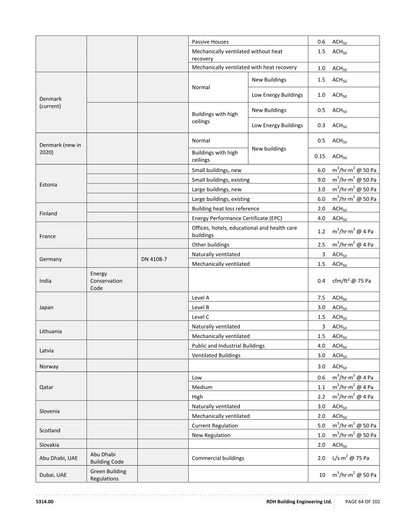
. . . . . . . . . . . . . . . . . . . . . . . . . . . . . . . . . . . . . . . . . . . . . . . . . . . . . . . . . . . . . . . . . . . . . . . . . . . . . . . . . . . . . . . . . . . . . . . . . . . . . . . . . . . . . . . . . . . . . .
5314.00 RDH Building Engineering Ltd.
....
PAGE 64 OF 102
Passive Houses 0.6 ACH50
Mechanically ventilated without heat recovery
1.5 ACH50
Mechanically ventilated with heat recovery 1.0 ACH50
Denmark (current)
Normal
New Buildings 1.5 ACH50
Low Energy Buildings 1.0 ACH50
Buildings with high ceilings
New Buildings 0.5 ACH50
Low Energy Buildings 0.3 ACH50
Denmark (new in 2020)
Normal
New buildings
0.5 ACH50
Buildings with high ceilings
0.15 ACH50
Estonia
Small buildings, new 6.0 m3/hr∙m2 @ 50 Pa
Small buildings, existing 9.0 m3/hr∙m2 @ 50 Pa
Large buildings, new 3.0 m3/hr∙m2 @ 50 Pa
Large buildings, existing 6.0 m3/hr∙m2 @ 50 Pa
Finland Building heat loss reference 2.0 ACH50
Energy Performance Certificate (EPC) 4.0 ACH50
France
Offices, hotels, educational and health care buildings
1.2 m3/hr∙m2 @ 4 Pa
Other buildings 2.5 m3/hr∙m2 @ 4 Pa
Germany DN 4108‐7 Naturally ventilated 3 ACH50
Mechanically ventilated 1.5 ACH50
India Energy Conservation Code
0.4 cfm/ft² @ 75 Pa
Japan
Level A 7.5 ACH50
Level B 3.0 ACH50
Level C 1.5 ACH50
Lithuania Naturally ventilated 3 ACH50
Mechanically ventilated 1.5 ACH50
Latvia Public and Industrial Buildings 4.0 ACH50
Ventilated Buildings 3.0 ACH50
Norway 3.0 ACH50
Qatar
Low 0.6 m3/hr∙m2 @ 4 Pa
Medium 1.1 m3/hr∙m2 @ 4 Pa
High 2.2 m3/hr∙m2 @ 4 Pa
Slovenia Naturally ventilated 3.0 ACH50
Mechanically ventilated 2.0 ACH50
Scotland Current Regulation 5.0 m3/hr∙m2 @ 50 Pa
New Regulation 1.0 m3/hr∙m2 @ 50 Pa
Slovakia 2.0 ACH50
Abu Dhabi, UAE Abu Dhabi Building Code
Commercial buildings 2.0 L/s∙m2 @ 75 Pa
Dubai, UAE Green Building Regulations
10 m3/hr∙m2 @ 50 Pa
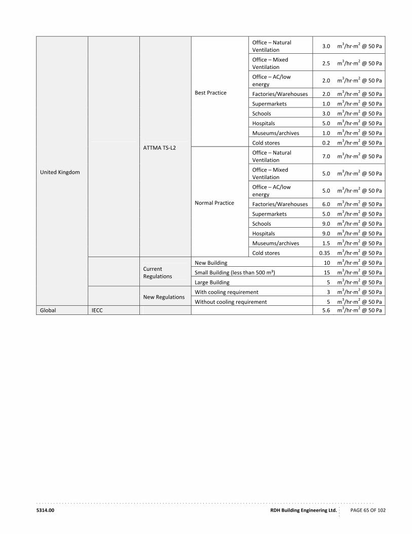
. . . . . . . . . . . . . . . . . . . . . . . . . . . . . . . . . . . . . . . . . . . . . . . . . . . . . . . . . . . . . . . . . . . . . . . . . . . . . . . . . . . . . . . . . . . . . . . . . . . . . . . . . . . . . . . . . . . . . .
5314.00 RDH Building Engineering Ltd.
....
PAGE 65 OF 102
United Kingdom
ATTMA TS‐L2
Best Practice
Office – Natural Ventilation
3.0 m3/hr∙m2 @ 50 Pa
Office – Mixed Ventilation
2.5 m3/hr∙m2 @ 50 Pa
Office – AC/low energy
2.0 m3/hr∙m2 @ 50 Pa
Factories/Warehouses 2.0 m3/hr∙m2 @ 50 Pa
Supermarkets 1.0 m3/hr∙m2 @ 50 Pa
Schools 3.0 m3/hr∙m2 @ 50 Pa
Hospitals 5.0 m3/hr∙m2 @ 50 Pa
Museums/archives 1.0 m3/hr∙m2 @ 50 Pa
Cold stores 0.2 m3/hr∙m2 @ 50 Pa
Normal Practice
Office – Natural Ventilation
7.0 m3/hr∙m2 @ 50 Pa
Office – Mixed Ventilation
5.0 m3/hr∙m2 @ 50 Pa
Office – AC/low energy
5.0 m3/hr∙m2 @ 50 Pa
Factories/Warehouses 6.0 m3/hr∙m2 @ 50 Pa
Supermarkets 5.0 m3/hr∙m2 @ 50 Pa
Schools 9.0 m3/hr∙m2 @ 50 Pa
Hospitals 9.0 m3/hr∙m2 @ 50 Pa
Museums/archives 1.5 m3/hr∙m2 @ 50 Pa
Cold stores 0.35 m3/hr∙m2 @ 50 Pa
Current Regulations
New Building 10 m3/hr∙m2 @ 50 Pa
Small Building (less than 500 m³) 15 m3/hr∙m2 @ 50 Pa
Large Building 5 m3/hr∙m2 @ 50 Pa
New Regulations With cooling requirement 3 m3/hr∙m2 @ 50 Pa
Without cooling requirement 5 m3/hr∙m2 @ 50 Pa
Global IECC 5.6 m3/hr∙m2 @ 50 Pa
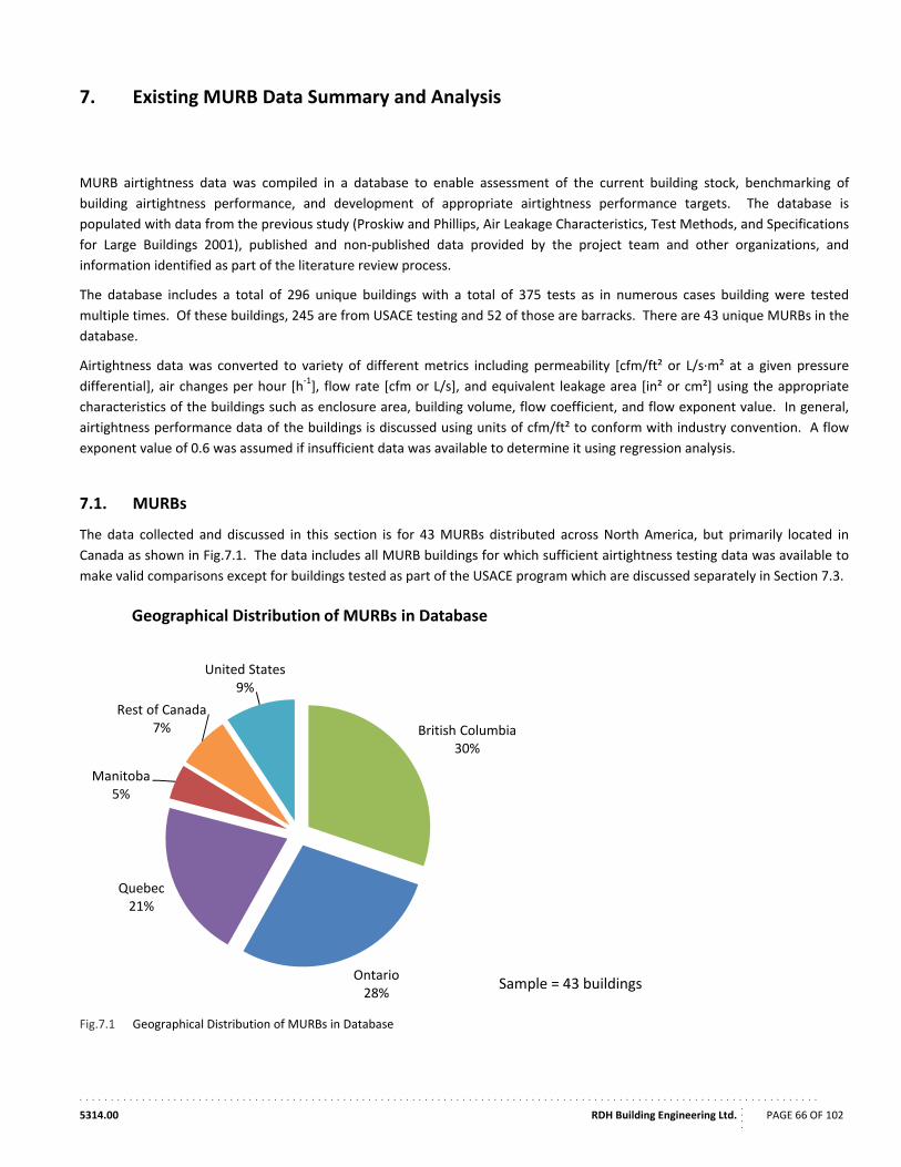
. . . . . . . . . . . . . . . . . . . . . . . . . . . . . . . . . . . . . . . . . . . . . . . . . . . . . . . . . . . . . . . . . . . . . . . . . . . . . . . . . . . . . . . . . . . . . . . . . . . . . . . . . . . . . . . . . . . . . .
5314.00 RDH Building Engineering Ltd.
....
PAGE 66 OF 102
7. Existing MURB Data Summary and Analysis
MURB airtightness data was compiled in a database to enable assessment of the current building stock, benchmarking of
building airtightness performance, and development of appropriate airtightness performance targets. The database is
populated with data from the previous study (Proskiw and Phillips, Air Leakage Characteristics, Test Methods, and Specifications
for Large Buildings 2001), published and non‐published data provided by the project team and other organizations, and
information identified as part of the literature review process.
The database includes a total of 296 unique buildings with a total of 375 tests as in numerous cases building were tested
multiple times. Of these buildings, 245 are from USACE testing and 52 of those are barracks. There are 43 unique MURBs in the
database.
Airtightness data was converted to variety of different metrics including permeability [cfm/ft² or L/s∙m² at a given pressure
differential], air changes per hour [h‐1], flow rate [cfm or L/s], and equivalent leakage area [in² or cm²] using the appropriate
characteristics of the buildings such as enclosure area, building volume, flow coefficient, and flow exponent value. In general,
airtightness performance data of the buildings is discussed using units of cfm/ft² to conform with industry convention. A flow
exponent value of 0.6 was assumed if insufficient data was available to determine it using regression analysis.
7.1. MURBs
The data collected and discussed in this section is for 43 MURBs distributed across North America, but primarily located in
Canada as shown in Fig.7.1. The data includes all MURB buildings for which sufficient airtightness testing data was available to
make valid comparisons except for buildings tested as part of the USACE program which are discussed separately in Section 7.3.
Fig.7.1 Geographical Distribution of MURBs in Database
British Columbia30%
Ontario28%
Quebec21%
Manitoba5%
Rest of Canada7%
United States9%
Geographical Distribution of MURBs in Database
Sample = 43 buildings
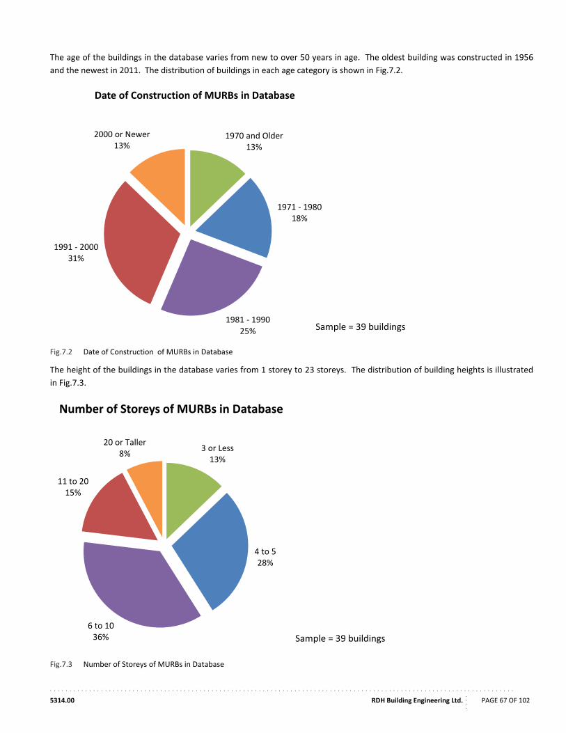
. . . . . . . . . . . . . . . . . . . . . . . . . . . . . . . . . . . . . . . . . . . . . . . . . . . . . . . . . . . . . . . . . . . . . . . . . . . . . . . . . . . . . . . . . . . . . . . . . . . . . . . . . . . . . . . . . . . . . .
5314.00 RDH Building Engineering Ltd.
....
PAGE 67 OF 102
The age of the buildings in the database varies from new to over 50 years in age. The oldest building was constructed in 1956
and the newest in 2011. The distribution of buildings in each age category is shown in Fig.7.2.
Fig.7.2 Date of Construction of MURBs in Database
The height of the buildings in the database varies from 1 storey to 23 storeys. The distribution of building heights is illustrated
in Fig.7.3.
Fig.7.3 Number of Storeys of MURBs in Database
1970 and Older13%
1971 ‐ 198018%
1981 ‐ 199025%
1991 ‐ 200031%
2000 or Newer13%
Date of Construction of MURBs in Database
Sample = 39 buildings
3 or Less13%
4 to 528%
6 to 1036%
11 to 2015%
20 or Taller8%
Number of Storeys of MURBs in Database
Sample = 39 buildings
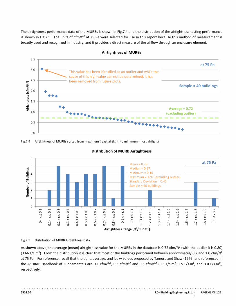
. . . . . . . . . . . . . . . . . . . . . . . . . . . . . . . . . . . . . . . . . . . . . . . . . . . . . . . . . . . . . . . . . . . . . . . . . . . . . . . . . . . . . . . . . . . . . . . . . . . . . . . . . . . . . . . . . . . . . .
5314.00 RDH Building Engineering Ltd.
....
PAGE 68 OF 102
The airtightness performance data of the MURBs is shown in Fig.7.4 and the distribution of the airtightness testing performance
is shown in Fig.7.5. The units of cfm/ft² at 75 Pa were selected for use in this report because this method of measurement is
broadly used and recognized in industry, and it provides a direct measure of the airflow through an enclosure element.
Fig.7.4 Airtightness of MURBs sorted from maximum (least airtight) to minimum (most airtight)
Fig.7.5 Distribution of MURB Airtightness Data
As shown above, the average (mean) airtightness value for the MURBs in the database is 0.72 cfm/ft² (with the outlier it is 0.80)
(3.66 L/s∙m²). From the distribution it is clear that most of the buildings performed between approximately 0.2 and 1.0 cfm/ft²
at 75 Pa. For reference, recall that the tight, average, and leaky values proposed by Tamura and Shaw (1976) and referenced in
the ASHRAE Handbook of Fundamentals are 0.1 cfm/ft², 0.3 cfm/ft² and 0.6 cfm/ft² (0.5 L/s∙m², 1.5 L/s∙m², and 3.0 L/s∙m²),
respectively.
0.0
0.5
1.0
1.5
2.0
2.5
3.0
3.5
Airightness [cfm
/ft²]
Airtightness of MURBs
Average = 0.72(excluding outlier)
at 75 Pa
This value has been identified as an outlier and while the cause of this high value can not be determined, it has been removed from future plots.
Sample = 40 buildings
0
1
2
3
4
5
6
0 < x ≤ 0.1
0.1 < x ≤ 0.2
0.2 < x ≤ 0.3
0.3 < x ≤ 0.4
0.4 < x ≤ 0.5
0.5 < x ≤ 0.6
0.6 < x ≤ 0.7
0.7 < x ≤ 0.8
0.8 < x ≤ 0.9
0.9 < x ≤ 1
1 < x ≤ 1.1
1.1 < x ≤ 1.2
1.2 < x ≤ 1.3
1.3 < x ≤ 1.4
1.4 < x ≤ 1.5
1.5 < x ≤ 1.6
1.6 < x ≤ 1.7
1.7 < x ≤ 1.8
1.8 < x ≤ 1.9
1.9 < x ≤ 2
Number of Build
ings
Airtightness Range [ft³/min∙ft²]
Distribution of MURB Airtightness
Mean = 0.78Median = 0.67Minimum = 0.16Maximum = 1.97 (excluding outlier)Standard Deviation = 0.45Sample = 40 buildings
at 75 Pa
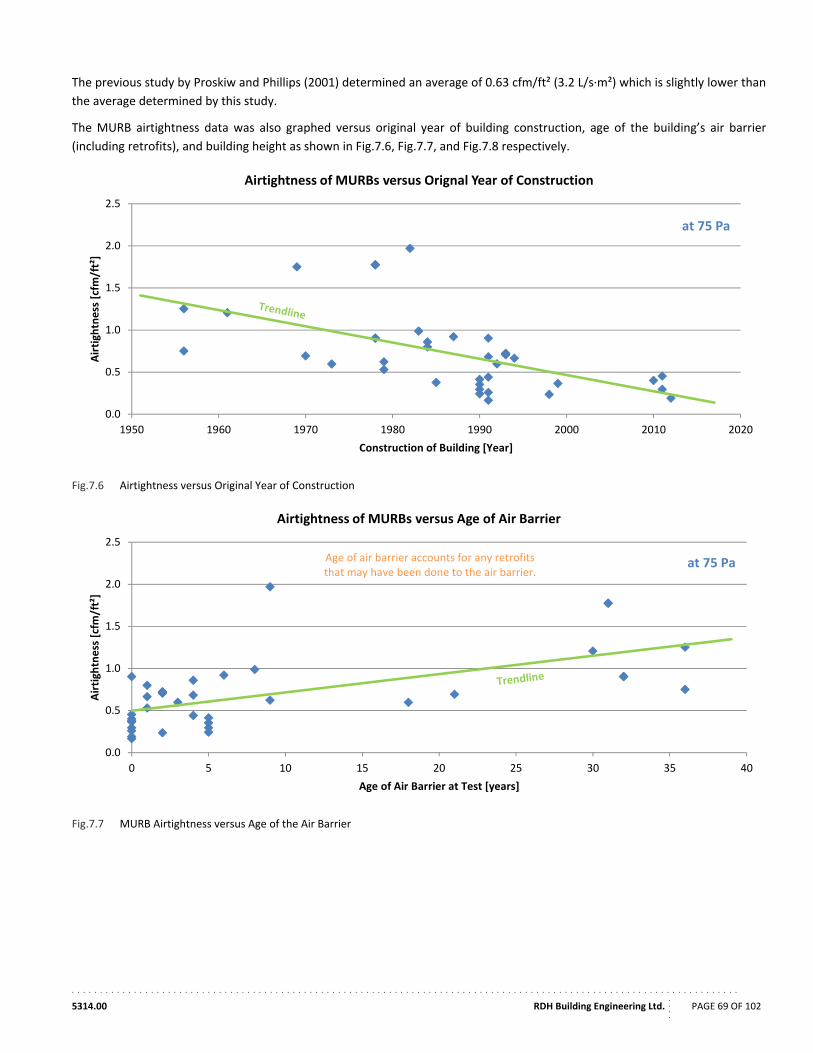
. . . . . . . . . . . . . . . . . . . . . . . . . . . . . . . . . . . . . . . . . . . . . . . . . . . . . . . . . . . . . . . . . . . . . . . . . . . . . . . . . . . . . . . . . . . . . . . . . . . . . . . . . . . . . . . . . . . . . .
5314.00 RDH Building Engineering Ltd.
....
PAGE 69 OF 102
The previous study by Proskiw and Phillips (2001) determined an average of 0.63 cfm/ft² (3.2 L/s∙m²) which is slightly lower than
the average determined by this study.
The MURB airtightness data was also graphed versus original year of building construction, age of the building’s air barrier
(including retrofits), and building height as shown in Fig.7.6, Fig.7.7, and Fig.7.8 respectively.
Fig.7.6 Airtightness versus Original Year of Construction
Fig.7.7 MURB Airtightness versus Age of the Air Barrier
0.0
0.5
1.0
1.5
2.0
2.5
1950 1960 1970 1980 1990 2000 2010 2020
Airtightness [cfm/ft²]
Construction of Building [Year]
Airtightness of MURBs versus Orignal Year of Construction
at 75 Pa
0.0
0.5
1.0
1.5
2.0
2.5
0 5 10 15 20 25 30 35 40
Airtightness [cfm/ft²]
Age of Air Barrier at Test [years]
Airtightness of MURBs versus Age of Air Barrier
Age of air barrier accounts for any retrofitsthat may have been done to the air barrier.
at 75 Pa
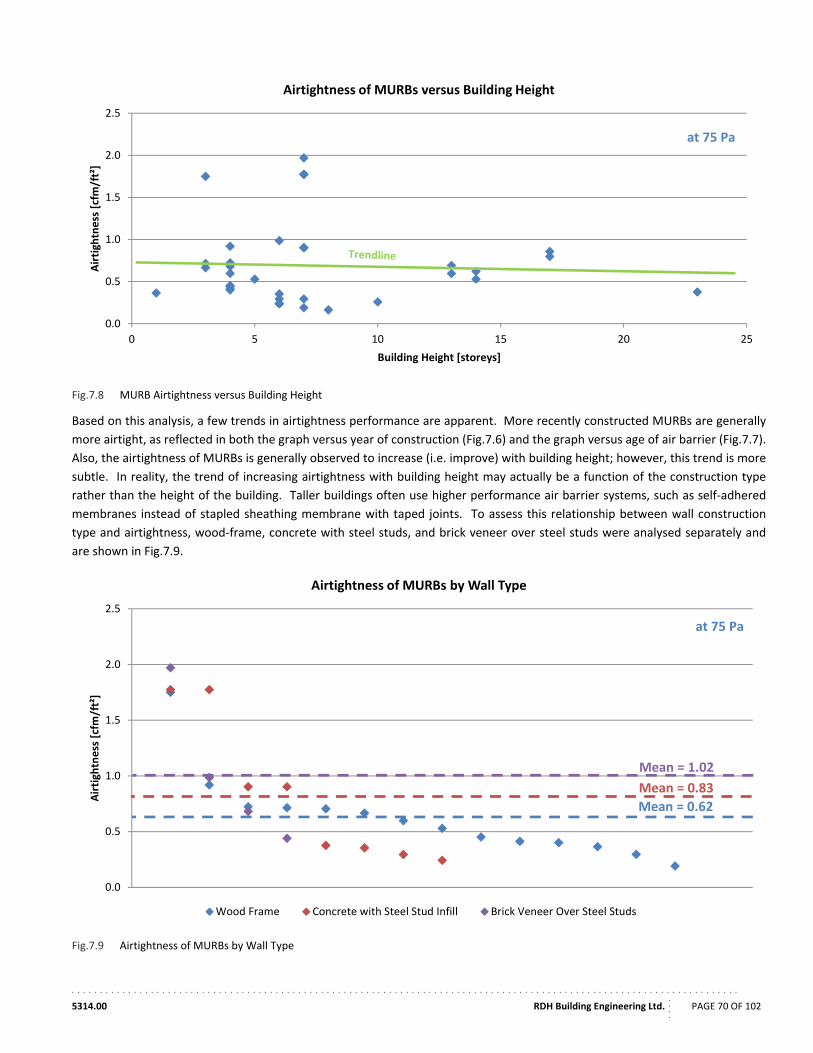
. . . . . . . . . . . . . . . . . . . . . . . . . . . . . . . . . . . . . . . . . . . . . . . . . . . . . . . . . . . . . . . . . . . . . . . . . . . . . . . . . . . . . . . . . . . . . . . . . . . . . . . . . . . . . . . . . . . . . .
5314.00 RDH Building Engineering Ltd.
....
PAGE 70 OF 102
Fig.7.8 MURB Airtightness versus Building Height
Based on this analysis, a few trends in airtightness performance are apparent. More recently constructed MURBs are generally
more airtight, as reflected in both the graph versus year of construction (Fig.7.6) and the graph versus age of air barrier (Fig.7.7).
Also, the airtightness of MURBs is generally observed to increase (i.e. improve) with building height; however, this trend is more
subtle. In reality, the trend of increasing airtightness with building height may actually be a function of the construction type
rather than the height of the building. Taller buildings often use higher performance air barrier systems, such as self‐adhered
membranes instead of stapled sheathing membrane with taped joints. To assess this relationship between wall construction
type and airtightness, wood‐frame, concrete with steel studs, and brick veneer over steel studs were analysed separately and
are shown in Fig.7.9.
Fig.7.9 Airtightness of MURBs by Wall Type
0.0
0.5
1.0
1.5
2.0
2.5
0 5 10 15 20 25
Airtightness [cfm/ft²]
Building Height [storeys]
Airtightness of MURBs versus Building Height
at 75 Pa
0.0
0.5
1.0
1.5
2.0
2.5
Airtightness [cfm/ft²]
Airtightness of MURBs by Wall Type
Wood Frame Concrete with Steel Stud Infill Brick Veneer Over Steel Studs
Mean = 0.62
at 75 Pa
Mean = 0.83
Mean = 1.02
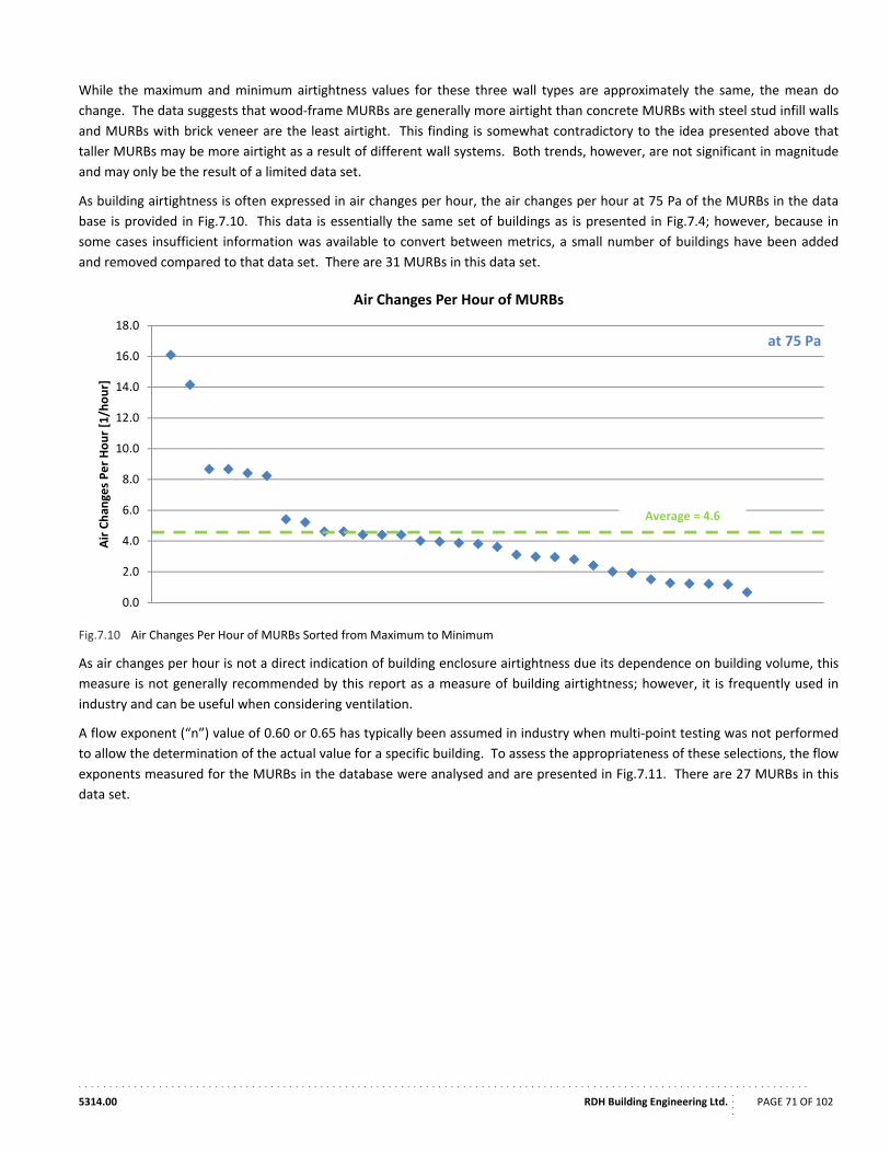
. . . . . . . . . . . . . . . . . . . . . . . . . . . . . . . . . . . . . . . . . . . . . . . . . . . . . . . . . . . . . . . . . . . . . . . . . . . . . . . . . . . . . . . . . . . . . . . . . . . . . . . . . . . . . . . . . . . . . .
5314.00 RDH Building Engineering Ltd.
....
PAGE 71 OF 102
While the maximum and minimum airtightness values for these three wall types are approximately the same, the mean do
change. The data suggests that wood‐frame MURBs are generally more airtight than concrete MURBs with steel stud infill walls
and MURBs with brick veneer are the least airtight. This finding is somewhat contradictory to the idea presented above that
taller MURBs may be more airtight as a result of different wall systems. Both trends, however, are not significant in magnitude
and may only be the result of a limited data set.
As building airtightness is often expressed in air changes per hour, the air changes per hour at 75 Pa of the MURBs in the data
base is provided in Fig.7.10. This data is essentially the same set of buildings as is presented in Fig.7.4; however, because in
some cases insufficient information was available to convert between metrics, a small number of buildings have been added
and removed compared to that data set. There are 31 MURBs in this data set.
Fig.7.10 Air Changes Per Hour of MURBs Sorted from Maximum to Minimum
As air changes per hour is not a direct indication of building enclosure airtightness due its dependence on building volume, this
measure is not generally recommended by this report as a measure of building airtightness; however, it is frequently used in
industry and can be useful when considering ventilation.
A flow exponent (“n”) value of 0.60 or 0.65 has typically been assumed in industry when multi‐point testing was not performed
to allow the determination of the actual value for a specific building. To assess the appropriateness of these selections, the flow
exponents measured for the MURBs in the database were analysed and are presented in Fig.7.11. There are 27 MURBs in this
data set.
0.0
2.0
4.0
6.0
8.0
10.0
12.0
14.0
16.0
18.0
Air Chan
ges Per Hour [1/hour]
Air Changes Per Hour of MURBs
Average = 4.6
at 75 Pa
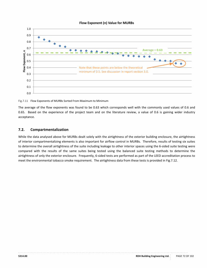
. . . . . . . . . . . . . . . . . . . . . . . . . . . . . . . . . . . . . . . . . . . . . . . . . . . . . . . . . . . . . . . . . . . . . . . . . . . . . . . . . . . . . . . . . . . . . . . . . . . . . . . . . . . . . . . . . . . . . .
5314.00 RDH Building Engineering Ltd.
....
PAGE 72 OF 102
Fig.7.11 Flow Exponents of MURBs Sorted From Maximum to Minimum
The average of the flow exponents was found to be 0.63 which corresponds well with the commonly used values of 0.6 and
0.65. Based on the experience of the project team and on the literature review, a value of 0.6 is gaining wider industry
acceptance.
7.2. Compartmentalization
While the data analysed above for MURBs dealt solely with the airtightness of the exterior building enclosure, the airtightness
of interior compartmentalizing elements is also important for airflow control in MURBs. Therefore, results of testing six suites
to determine the overall airtightness of the suite including leakage to other interior spaces using the 6‐sided suite testing were
compared with the results of the same suites being tested using the balanced suite testing methods to determine the
airtightness of only the exterior enclosure. Frequently, 6‐sided tests are performed as part of the LEED accreditation process to
meet the environmental tobacco smoke requirement. The airtightness data from these tests is provided in Fig.7.12.
0.0
0.1
0.2
0.3
0.4
0.5
0.6
0.7
0.8
0.9
1.0
Flow Exponent, n
Flow Exponent (n) Value for MURBs
Average = 0.63
Note that these points are below the theoretical minimum of 0.5. See discussion in report section 3.0.
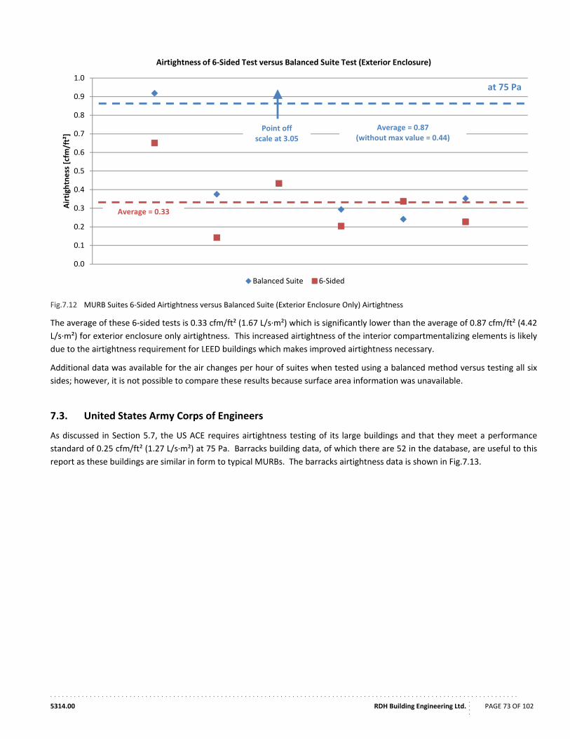
. . . . . . . . . . . . . . . . . . . . . . . . . . . . . . . . . . . . . . . . . . . . . . . . . . . . . . . . . . . . . . . . . . . . . . . . . . . . . . . . . . . . . . . . . . . . . . . . . . . . . . . . . . . . . . . . . . . . . .
5314.00 RDH Building Engineering Ltd.
....
PAGE 73 OF 102
Fig.7.12 MURB Suites 6‐Sided Airtightness versus Balanced Suite (Exterior Enclosure Only) Airtightness
The average of these 6‐sided tests is 0.33 cfm/ft² (1.67 L/s∙m²) which is significantly lower than the average of 0.87 cfm/ft² (4.42
L/s∙m²) for exterior enclosure only airtightness. This increased airtightness of the interior compartmentalizing elements is likely
due to the airtightness requirement for LEED buildings which makes improved airtightness necessary.
Additional data was available for the air changes per hour of suites when tested using a balanced method versus testing all six
sides; however, it is not possible to compare these results because surface area information was unavailable.
7.3. United States Army Corps of Engineers
As discussed in Section 5.7, the US ACE requires airtightness testing of its large buildings and that they meet a performance
standard of 0.25 cfm/ft² (1.27 L/s∙m²) at 75 Pa. Barracks building data, of which there are 52 in the database, are useful to this
report as these buildings are similar in form to typical MURBs. The barracks airtightness data is shown in Fig.7.13.
0.0
0.1
0.2
0.3
0.4
0.5
0.6
0.7
0.8
0.9
1.0
Airtigh
tness [cfm/ft²]
Airtightness of 6‐Sided Test versus Balanced Suite Test (Exterior Enclosure)
Balanced Suite 6‐Sided
at 75 Pa
Point offscale at 3.05
Average = 0.33
Average = 0.87(without max value = 0.44)
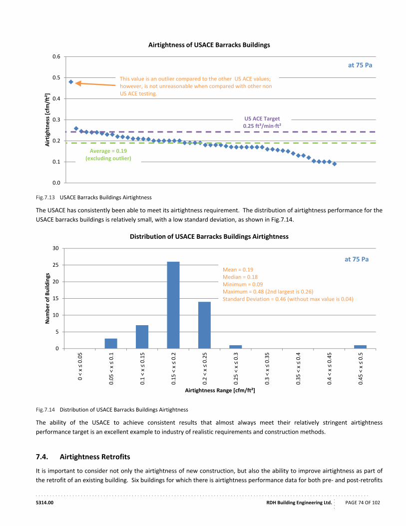
. . . . . . . . . . . . . . . . . . . . . . . . . . . . . . . . . . . . . . . . . . . . . . . . . . . . . . . . . . . . . . . . . . . . . . . . . . . . . . . . . . . . . . . . . . . . . . . . . . . . . . . . . . . . . . . . . . . . . .
5314.00 RDH Building Engineering Ltd.
....
PAGE 74 OF 102
Fig.7.13 USACE Barracks Buildings Airtightness
The USACE has consistently been able to meet its airtightness requirement. The distribution of airtightness performance for the
USACE barracks buildings is relatively small, with a low standard deviation, as shown in Fig.7.14.
Fig.7.14 Distribution of USACE Barracks Buildings Airtightness
The ability of the USACE to achieve consistent results that almost always meet their relatively stringent airtightness
performance target is an excellent example to industry of realistic requirements and construction methods.
7.4. Airtightness Retrofits
It is important to consider not only the airtightness of new construction, but also the ability to improve airtightness as part of
the retrofit of an existing building. Six buildings for which there is airtightness performance data for both pre‐ and post‐retrofits
0.0
0.1
0.2
0.3
0.4
0.5
0.6
Airtigh
tness [cfm/ft²]
Airtightness of USACE Barracks Buildings
Average = 0.19(excluding outlier)
at 75 Pa
This value is an outlier compared to the other US ACE values; however, is not unreasonable when compared with other non US ACE testing.
US ACE Target0.25 ft³/min∙ft²
0
5
10
15
20
25
30
0 < x ≤ 0.05
0.05 < x ≤ 0.1
0.1 < x ≤ 0.15
0.15 < x ≤ 0.2
0.2 < x ≤ 0.25
0.25 < x ≤ 0.3
0.3 < x ≤ 0.35
0.35 < x ≤ 0.4
0.4 < x ≤ 0.45
0.45 < x ≤ 0.5
Number of Build
ings
Airtightness Range [cfm/ft²]
Distribution of USACE Barracks Buildings Airtightness
Mean = 0.19Median = 0.18Minimum = 0.09Maximum = 0.48 (2nd largest is 0.26)Standard Deviation = 0.46 (without max value is 0.04)
at 75 Pa
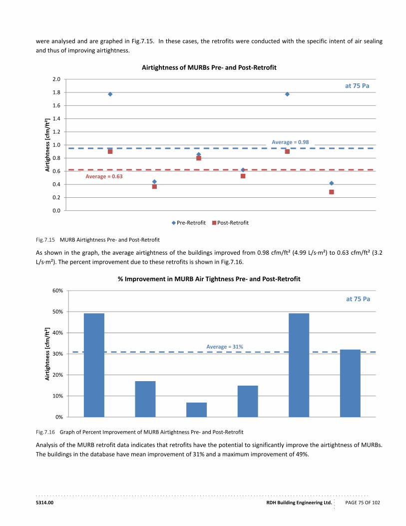
. . . . . . . . . . . . . . . . . . . . . . . . . . . . . . . . . . . . . . . . . . . . . . . . . . . . . . . . . . . . . . . . . . . . . . . . . . . . . . . . . . . . . . . . . . . . . . . . . . . . . . . . . . . . . . . . . . . . . .
5314.00 RDH Building Engineering Ltd.
....
PAGE 75 OF 102
were analysed and are graphed in Fig.7.15. In these cases, the retrofits were conducted with the specific intent of air sealing
and thus of improving airtightness.
Fig.7.15 MURB Airtightness Pre‐ and Post‐Retrofit
As shown in the graph, the average airtightness of the buildings improved from 0.98 cfm/ft² (4.99 L/s∙m²) to 0.63 cfm/ft² (3.2
L/s∙m²). The percent improvement due to these retrofits is shown in Fig.7.16.
Fig.7.16 Graph of Percent Improvement of MURB Airtightness Pre‐ and Post‐Retrofit
Analysis of the MURB retrofit data indicates that retrofits have the potential to significantly improve the airtightness of MURBs.
The buildings in the database have mean improvement of 31% and a maximum improvement of 49%.
0.0
0.2
0.4
0.6
0.8
1.0
1.2
1.4
1.6
1.8
2.0
Airtightness [cfm/ft²]
Airtightness of MURBs Pre‐ and Post‐Retrofit
Pre‐Retrofit Post‐Retrofit
at 75 Pa
Average = 0.63
Average = 0.98
0%
10%
20%
30%
40%
50%
60%
Airtightness [cfm
/ft²]
% Improvement in MURB Air Tightness Pre‐ and Post‐Retrofit
at 75 Pa
Average = 31%
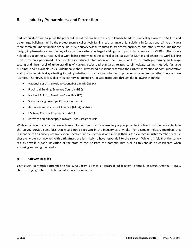
. . . . . . . . . . . . . . . . . . . . . . . . . . . . . . . . . . . . . . . . . . . . . . . . . . . . . . . . . . . . . . . . . . . . . . . . . . . . . . . . . . . . . . . . . . . . . . . . . . . . . . . . . . . . . . . . . . . . . .
5314.00 RDH Building Engineering Ltd.
....
PAGE 76 OF 102
8. Industry Preparedness and Perception
Part of this study was to gauge the preparedness of the building industry in Canada to address air leakage control in MURBs and
other large buildings. While the project team is collectively familiar with a range of jurisdictions in Canada and US, to achieve a
more complete understanding of the industry, a survey was distributed to architects, engineers, and others responsible for the
design, implementation and testing of air barrier systems in large buildings, with particular attention to MURBs. The survey
helped to gauge the current level of work being performed in the control of air leakage for MURBs and where this work is being
most commonly performed. The results also included information on the number of firms currently performing air leakage
testing and their level of understanding of current codes and standards related to air leakage testing methods for large
buildings, and if available costs. Additionally, the survey asked questions regarding the current perception of both quantitative
and qualitative air leakage testing including whether it is effective, whether it provides a value, and whether the costs are
justified. The survey is provided in its entirety in Appendix C. It was distributed through the following channels:
National Building Envelope Council of Canada (NBEC)
Provincial Building Envelope Councils (BECs)
National Building Envelope Council (NBEC)
State Building Envelope Councils in the US
Air Barrier Association of America (AABA) Website
US Army Corps of Engineers (USACE)
Retrotec and Minneapolis Blower Door Customer Lists
While effort was made by this research group to reach as broad of a sample group as possible, it is likely that the respondents to
this survey provide some bias that would not be present in the industry as a whole. For example, industry members that
responded to this survey are likely more involved with airtightness of buildings than is the average industry member because
those who are not involved with airtightness are less likely to have responded to the survey. While it is felt that the survey
results provide a good indication of the state of the industry, the potential bias such as this should be considered when
analyzing and using the results.
8.1. Survey Results
Sixty‐seven individuals responded to the survey from a range of geographical locations primarily in North America. Fig.8.1
shows the geographical distribution of survey respondents.
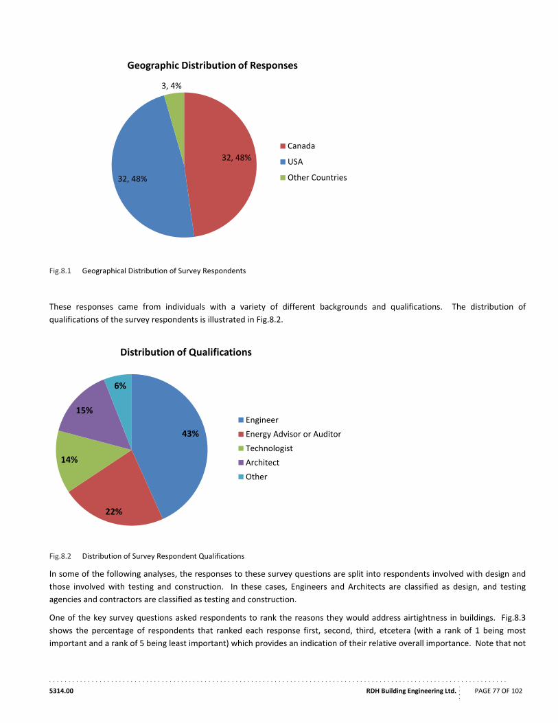
. . . . . . . . . . . . . . . . . . . . . . . . . . . . . . . . . . . . . . . . . . . . . . . . . . . . . . . . . . . . . . . . . . . . . . . . . . . . . . . . . . . . . . . . . . . . . . . . . . . . . . . . . . . . . . . . . . . . . .
5314.00 RDH Building Engineering Ltd.
....
PAGE 77 OF 102
Fig.8.1 Geographical Distribution of Survey Respondents
These responses came from individuals with a variety of different backgrounds and qualifications. The distribution of
qualifications of the survey respondents is illustrated in Fig.8.2.
Fig.8.2 Distribution of Survey Respondent Qualifications
In some of the following analyses, the responses to these survey questions are split into respondents involved with design and
those involved with testing and construction. In these cases, Engineers and Architects are classified as design, and testing
agencies and contractors are classified as testing and construction.
One of the key survey questions asked respondents to rank the reasons they would address airtightness in buildings. Fig.8.3
shows the percentage of respondents that ranked each response first, second, third, etcetera (with a rank of 1 being most
important and a rank of 5 being least important) which provides an indication of their relative overall importance. Note that not
32, 48%
32, 48%
3, 4%
Geographic Distribution of Responses
Canada
USA
Other Countries
43%
22%
14%
15%
6%
Distribution of Qualifications
Engineer
Energy Advisor or Auditor
Technologist
Architect
Other
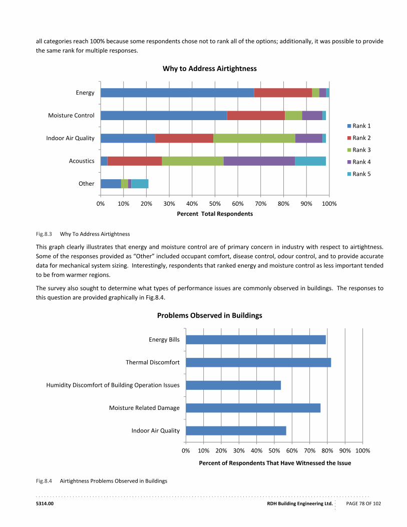
. . . . . . . . . . . . . . . . . . . . . . . . . . . . . . . . . . . . . . . . . . . . . . . . . . . . . . . . . . . . . . . . . . . . . . . . . . . . . . . . . . . . . . . . . . . . . . . . . . . . . . . . . . . . . . . . . . . . . .
5314.00 RDH Building Engineering Ltd.
....
PAGE 78 OF 102
all categories reach 100% because some respondents chose not to rank all of the options; additionally, it was possible to provide
the same rank for multiple responses.
Fig.8.3 Why To Address Airtightness
This graph clearly illustrates that energy and moisture control are of primary concern in industry with respect to airtightness.
Some of the responses provided as “Other” included occupant comfort, disease control, odour control, and to provide accurate
data for mechanical system sizing. Interestingly, respondents that ranked energy and moisture control as less important tended
to be from warmer regions.
The survey also sought to determine what types of performance issues are commonly observed in buildings. The responses to
this question are provided graphically in Fig.8.4.
Fig.8.4 Airtightness Problems Observed in Buildings
0% 10% 20% 30% 40% 50% 60% 70% 80% 90% 100%
Energy
Moisture Control
Indoor Air Quality
Acoustics
Other
Percent Total Respondents
Why to Address Airtightness
Rank 1
Rank 2
Rank 3
Rank 4
Rank 5
0% 10% 20% 30% 40% 50% 60% 70% 80% 90% 100%
Energy Bills
Thermal Discomfort
Humidity Discomfort of Building Operation Issues
Moisture Related Damage
Indoor Air Quality
Percent of Respondents That Have Witnessed the Issue
Problems Observed in Buildings
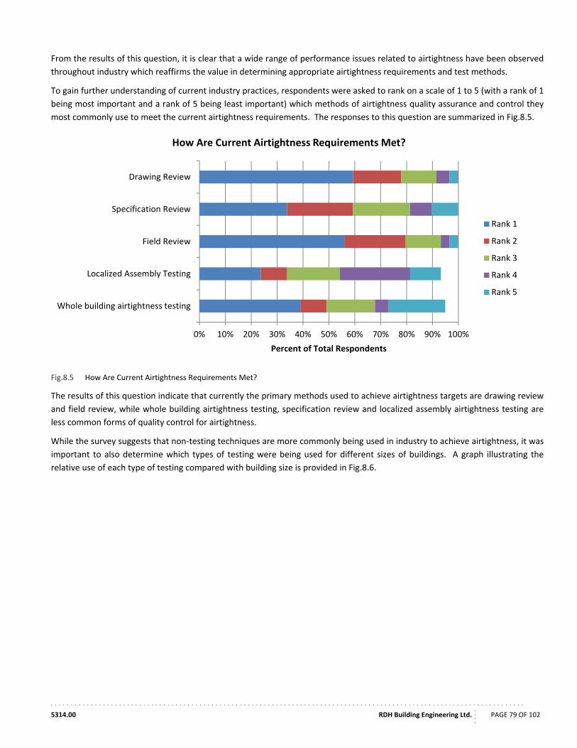
. . . . . . . . . . . . . . . . . . . . . . . . . . . . . . . . . . . . . . . . . . . . . . . . . . . . . . . . . . . . . . . . . . . . . . . . . . . . . . . . . . . . . . . . . . . . . . . . . . . . . . . . . . . . . . . . . . . . . .
5314.00 RDH Building Engineering Ltd.
....
PAGE 79 OF 102
From the results of this question, it is clear that a wide range of performance issues related to airtightness have been observed
throughout industry which reaffirms the value in determining appropriate airtightness requirements and test methods.
To gain further understanding of current industry practices, respondents were asked to rank on a scale of 1 to 5 (with a rank of 1
being most important and a rank of 5 being least important) which methods of airtightness quality assurance and control they
most commonly use to meet the current airtightness requirements. The responses to this question are summarized in Fig.8.5.
Fig.8.5 How Are Current Airtightness Requirements Met?
The results of this question indicate that currently the primary methods used to achieve airtightness targets are drawing review
and field review, while whole building airtightness testing, specification review and localized assembly airtightness testing are
less common forms of quality control for airtightness.
While the survey suggests that non‐testing techniques are more commonly being used in industry to achieve airtightness, it was
important to also determine which types of testing were being used for different sizes of buildings. A graph illustrating the
relative use of each type of testing compared with building size is provided in Fig.8.6.
0% 10% 20% 30% 40% 50% 60% 70% 80% 90% 100%
Drawing Review
Specification Review
Field Review
Localized Assembly Testing
Whole building airtightness testing
Percent of Total Respondents
How Are Current Airtightness Requirements Met?
Rank 1
Rank 2
Rank 3
Rank 4
Rank 5
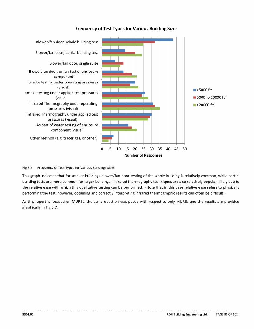
. . . . . . . . . . . . . . . . . . . . . . . . . . . . . . . . . . . . . . . . . . . . . . . . . . . . . . . . . . . . . . . . . . . . . . . . . . . . . . . . . . . . . . . . . . . . . . . . . . . . . . . . . . . . . . . . . . . . . .
5314.00 RDH Building Engineering Ltd.
....
PAGE 80 OF 102
Fig.8.6 Frequency of Test Types for Various Buildings Sizes
This graph indicates that for smaller buildings blower/fan‐door testing of the whole building is relatively common, while partial
building tests are more common for larger buildings. Infrared thermography techniques are also relatively popular, likely due to
the relative ease with which this qualitative testing can be performed. (Note that in this case relative ease refers to physically
performing the test; however, obtaining and correctly interpreting infrared thermographic results can often be difficult.)
As this report is focused on MURBs, the same question was posed with respect to only MURBs and the results are provided
graphically in Fig.8.7.
0 5 10 15 20 25 30 35 40 45 50
Blower/fan door, whole building test
Blower/fan door, partial building test
Blower/fan door, single suite
Blower/fan door, or fan test of enclosurecomponent
Smoke testing under operating pressures(visual)
Smoke testing under applied test pressures(visual)
Infrared Thermography under operatingpressures (visual)
Infrared Thermography under applied testpressures (visual)
As part of water testing of enclosurecomponent (visual)
Other Method (e.g. tracer gas, or other)
Number of Responses
Frequency of Test Types for Various Building Sizes
<5000 ft²
5000 to 20000 ft²
>20000 ft²
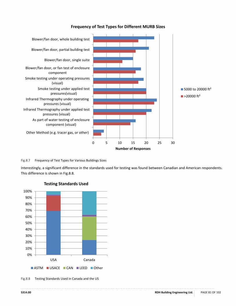
. . . . . . . . . . . . . . . . . . . . . . . . . . . . . . . . . . . . . . . . . . . . . . . . . . . . . . . . . . . . . . . . . . . . . . . . . . . . . . . . . . . . . . . . . . . . . . . . . . . . . . . . . . . . . . . . . . . . . .
5314.00 RDH Building Engineering Ltd.
....
PAGE 81 OF 102
Fig.8.7 Frequency of Test Types for Various Buildings Sizes
Interestingly, a significant difference in the standards used for testing was found between Canadian and American respondents.
This difference is shown in Fig.8.8.
Fig.8.8 Testing Standards Used in Canada and the US
0 5 10 15 20 25 30
Blower/fan door, whole building test
Blower/fan door, partial building test
Blower/fan door, single suite
Blower/fan door, or fan test of enclosurecomponent
Smoke testing under operating pressures(visual)
Smoke testing under applied testpressures(visual)
Infrared Thermography under operatingpressures (visual)
Infrared Thermography under applied testpressures (visual)
As part of water testing of enclosurecomponent (visual)
Other Method (e.g. tracer gas, or other)
Number of Responses
Frequency of Test Types for Different MURB Sizes
5000 to 20000 ft²
>20000 ft²
0%
10%
20%
30%
40%
50%
60%
70%
80%
90%
100%
CanadaUSA
Testing Standards Used
ASTM USACE CAN LEED Other
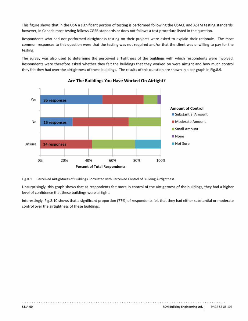
. . . . . . . . . . . . . . . . . . . . . . . . . . . . . . . . . . . . . . . . . . . . . . . . . . . . . . . . . . . . . . . . . . . . . . . . . . . . . . . . . . . . . . . . . . . . . . . . . . . . . . . . . . . . . . . . . . . . . .
5314.00 RDH Building Engineering Ltd.
....
PAGE 82 OF 102
This figure shows that in the USA a significant portion of testing is performed following the USACE and ASTM testing standards;
however, in Canada most testing follows CGSB standards or does not follows a test procedure listed in the question.
Respondents who had not performed airtightness testing on their projects were asked to explain their rationale. The most
common responses to this question were that the testing was not required and/or that the client was unwilling to pay for the
testing.
The survey was also used to determine the perceived airtightness of the buildings with which respondents were involved.
Respondents were therefore asked whether they felt the buildings that they worked on were airtight and how much control
they felt they had over the airtightness of these buildings. The results of this question are shown in a bar graph in Fig.8.9.
Fig.8.9 Perceived Airtightness of Buildings Correlated with Perceived Control of Building Airtightness
Unsurprisingly, this graph shows that as respondents felt more in control of the airtightness of the buildings, they had a higher
level of confidence that these buildings were airtight.
Interestingly, Fig.8.10 shows that a significant proportion (77%) of respondents felt that they had either substantial or moderate
control over the airtightness of these buildings.
0% 20% 40% 60% 80% 100%
Yes
No
Unsure
Percent of Total Respondents
Are The Buildings You Have Worked On Airtight?
Substantial Amount
Moderate Amount
Small Amount
None
Not Sure
Amount of Control
35 responses
15 responses
14 responses
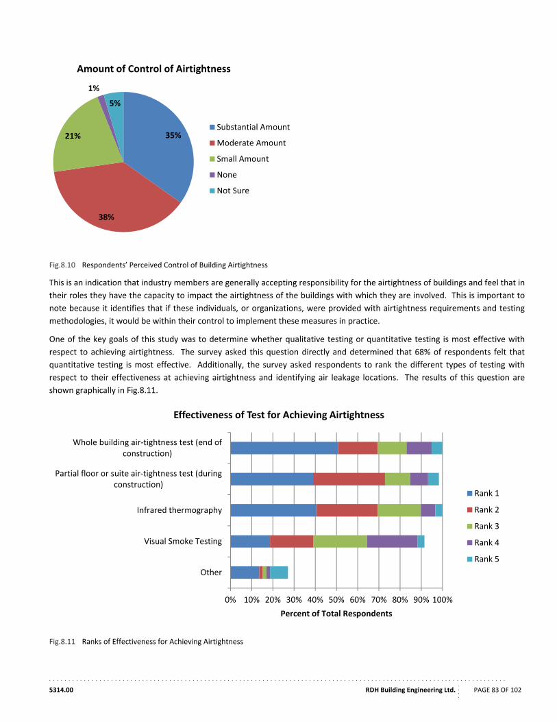
. . . . . . . . . . . . . . . . . . . . . . . . . . . . . . . . . . . . . . . . . . . . . . . . . . . . . . . . . . . . . . . . . . . . . . . . . . . . . . . . . . . . . . . . . . . . . . . . . . . . . . . . . . . . . . . . . . . . . .
5314.00 RDH Building Engineering Ltd.
....
PAGE 83 OF 102
Fig.8.10 Respondents’ Perceived Control of Building Airtightness
This is an indication that industry members are generally accepting responsibility for the airtightness of buildings and feel that in
their roles they have the capacity to impact the airtightness of the buildings with which they are involved. This is important to
note because it identifies that if these individuals, or organizations, were provided with airtightness requirements and testing
methodologies, it would be within their control to implement these measures in practice.
One of the key goals of this study was to determine whether qualitative testing or quantitative testing is most effective with
respect to achieving airtightness. The survey asked this question directly and determined that 68% of respondents felt that
quantitative testing is most effective. Additionally, the survey asked respondents to rank the different types of testing with
respect to their effectiveness at achieving airtightness and identifying air leakage locations. The results of this question are
shown graphically in Fig.8.11.
Fig.8.11 Ranks of Effectiveness for Achieving Airtightness
35%
38%
21%
1%
5%
Amount of Control of Airtightness
Substantial Amount
Moderate Amount
Small Amount
None
Not Sure
0% 10% 20% 30% 40% 50% 60% 70% 80% 90% 100%
Whole building air‐tightness test (end ofconstruction)
Partial floor or suite air‐tightness test (duringconstruction)
Infrared thermography
Visual Smoke Testing
Other
Percent of Total Respondents
Effectiveness of Test for Achieving Airtightness
Rank 1
Rank 2
Rank 3
Rank 4
Rank 5
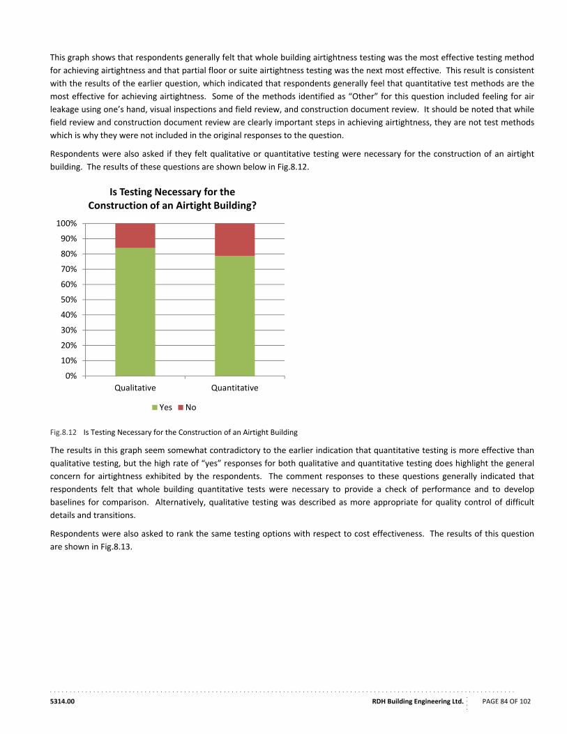
. . . . . . . . . . . . . . . . . . . . . . . . . . . . . . . . . . . . . . . . . . . . . . . . . . . . . . . . . . . . . . . . . . . . . . . . . . . . . . . . . . . . . . . . . . . . . . . . . . . . . . . . . . . . . . . . . . . . . .
5314.00 RDH Building Engineering Ltd.
....
PAGE 84 OF 102
This graph shows that respondents generally felt that whole building airtightness testing was the most effective testing method
for achieving airtightness and that partial floor or suite airtightness testing was the next most effective. This result is consistent
with the results of the earlier question, which indicated that respondents generally feel that quantitative test methods are the
most effective for achieving airtightness. Some of the methods identified as “Other” for this question included feeling for air
leakage using one’s hand, visual inspections and field review, and construction document review. It should be noted that while
field review and construction document review are clearly important steps in achieving airtightness, they are not test methods
which is why they were not included in the original responses to the question.
Respondents were also asked if they felt qualitative or quantitative testing were necessary for the construction of an airtight
building. The results of these questions are shown below in Fig.8.12.
Fig.8.12 Is Testing Necessary for the Construction of an Airtight Building
The results in this graph seem somewhat contradictory to the earlier indication that quantitative testing is more effective than
qualitative testing, but the high rate of “yes” responses for both qualitative and quantitative testing does highlight the general
concern for airtightness exhibited by the respondents. The comment responses to these questions generally indicated that
respondents felt that whole building quantitative tests were necessary to provide a check of performance and to develop
baselines for comparison. Alternatively, qualitative testing was described as more appropriate for quality control of difficult
details and transitions.
Respondents were also asked to rank the same testing options with respect to cost effectiveness. The results of this question
are shown in Fig.8.13.
0%
10%
20%
30%
40%
50%
60%
70%
80%
90%
100%
QuantitativeQualitative
Is Testing Necessary for theConstruction of an Airtight Building?
Yes No
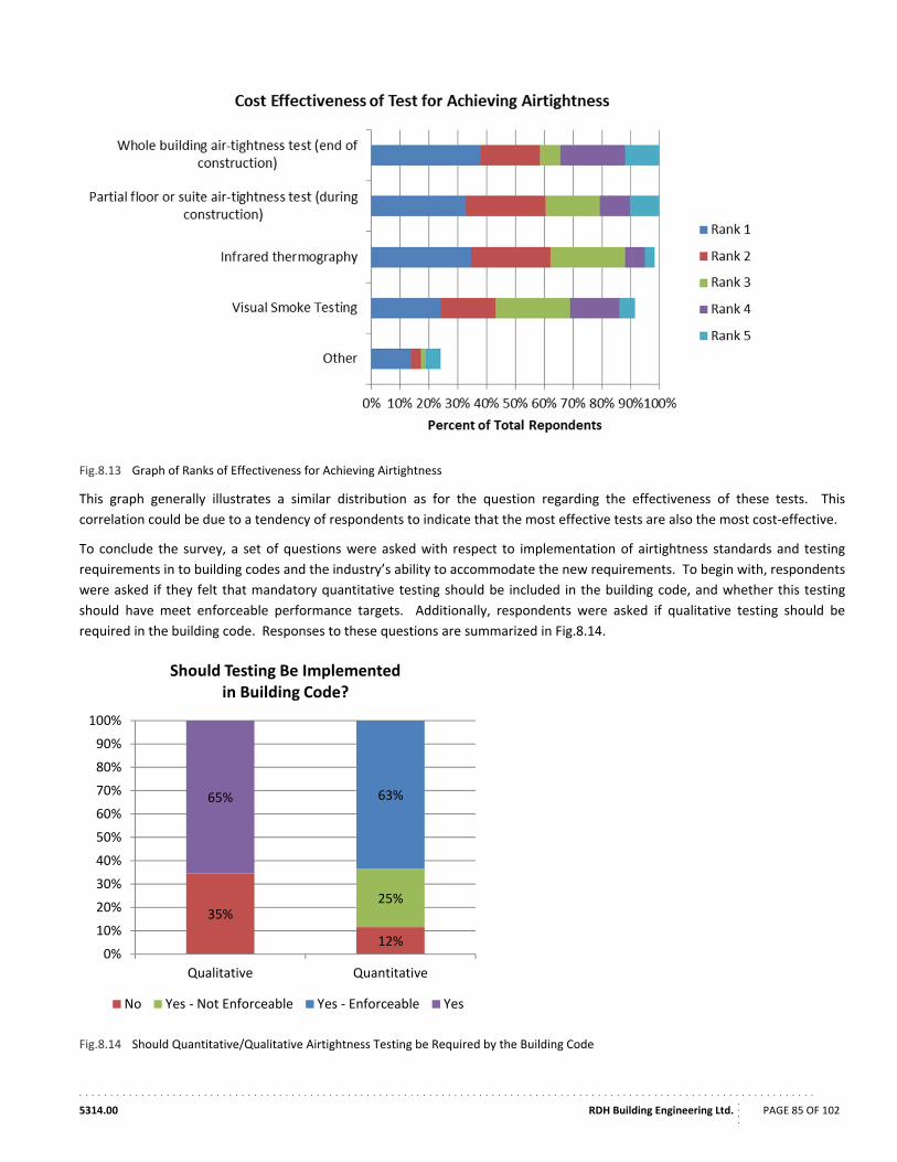
. . . . . . . . . . . . . . . . . . . . . . . . . . . . . . . . . . . . . . . . . . . . . . . . . . . . . . . . . . . . . . . . . . . . . . . . . . . . . . . . . . . . . . . . . . . . . . . . . . . . . . . . . . . . . . . . . . . . . .
5314.00 RDH Building Engineering Ltd.
....
PAGE 85 OF 102
Fig.8.13 Graph of Ranks of Effectiveness for Achieving Airtightness
This graph generally illustrates a similar distribution as for the question regarding the effectiveness of these tests. This
correlation could be due to a tendency of respondents to indicate that the most effective tests are also the most cost‐effective.
To conclude the survey, a set of questions were asked with respect to implementation of airtightness standards and testing
requirements in to building codes and the industry’s ability to accommodate the new requirements. To begin with, respondents
were asked if they felt that mandatory quantitative testing should be included in the building code, and whether this testing
should have meet enforceable performance targets. Additionally, respondents were asked if qualitative testing should be
required in the building code. Responses to these questions are summarized in Fig.8.14.
Fig.8.14 Should Quantitative/Qualitative Airtightness Testing be Required by the Building Code
12%
35%25%
63%65%
0%
10%
20%
30%
40%
50%
60%
70%
80%
90%
100%
QuantitativeQualitative
Should Testing Be Implementedin Building Code?
No Yes ‐ Not Enforceable Yes ‐ Enforceable Yes
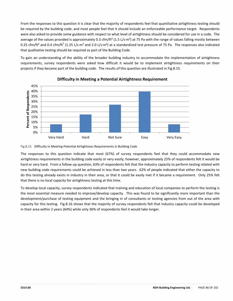
. . . . . . . . . . . . . . . . . . . . . . . . . . . . . . . . . . . . . . . . . . . . . . . . . . . . . . . . . . . . . . . . . . . . . . . . . . . . . . . . . . . . . . . . . . . . . . . . . . . . . . . . . . . . . . . . . . . . . .
5314.00 RDH Building Engineering Ltd.
....
PAGE 86 OF 102
From the responses to this question it is clear that the majority of respondents feel that quantitative airtightness testing should
be required by the building code, and most people feel that it should include an enforceable performance target. Respondents
were also asked to provide some guidance with respect to what level of airtightness should be considered for use in a code. The
average of the values provided is approximately 0.3 cfm/ft² (1.5 L/s∙m²) at 75 Pa with the range of values falling mostly between
0.25 cfm/ft² and 0.4 cfm/ft2 (1.25 L/s∙m² and 2.0 L/s∙m²) at a standardized test pressure of 75 Pa. The responses also indicated
that qualitative testing should be required as part of the Building Code.
To gain an understanding of the ability of the broader building industry to accommodate the implementation of airtightness
requirements, survey respondents were asked how difficult it would be to implement airtightness requirements on their
projects if they became part of the building code. The results of this question are illustrated in Fig.8.15.
Fig.8.15 Difficulty in Meeting Potential Airtightness Requirements in Building Code
The responses to this question indicate that most (67%) of survey respondents feel that they could accommodate new
airtightness requirements in the building code easily or very easily; however, approximately 25% of respondents felt it would be
hard or very hard. From a follow‐up question, 63% of respondents felt that the industry capacity to perform testing related with
new building code requirements could be achieved in less than two years. 62% of people indicated that either the capacity to
do this testing already exists in industry in their area, or that it could be easily met if it became a requirement. Only 25% felt
that there is no local capacity for airtightness testing at this time.
To develop local capacity, survey respondents indicated that training and education of local companies to perform the testing is
the most essential measure needed to improve/develop capacity. This was found to be significantly more important than the
development/purchase of testing equipment and the bringing in of consultants or testing agencies from out of the area with
capacity for this testing. Fig.8.16 shows that the majority of survey respondents felt that industry capacity could be developed
in their area within 2 years (64%) while only 36% of respondents feel it would take longer.
0%
5%
10%
15%
20%
25%
30%
35%
40%
45%
Very EasyEasyNot SureHardVery Hard
Percent of Respondents
Difficulty in Meeting a Potential Airtightness Requirement
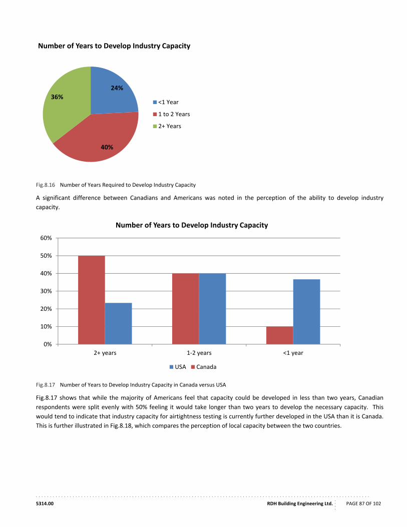
. . . . . . . . . . . . . . . . . . . . . . . . . . . . . . . . . . . . . . . . . . . . . . . . . . . . . . . . . . . . . . . . . . . . . . . . . . . . . . . . . . . . . . . . . . . . . . . . . . . . . . . . . . . . . . . . . . . . . .
5314.00 RDH Building Engineering Ltd.
....
PAGE 87 OF 102
Fig.8.16 Number of Years Required to Develop Industry Capacity
A significant difference between Canadians and Americans was noted in the perception of the ability to develop industry
capacity.
Fig.8.17 Number of Years to Develop Industry Capacity in Canada versus USA
Fig.8.17 shows that while the majority of Americans feel that capacity could be developed in less than two years, Canadian
respondents were split evenly with 50% feeling it would take longer than two years to develop the necessary capacity. This
would tend to indicate that industry capacity for airtightness testing is currently further developed in the USA than it is Canada.
This is further illustrated in Fig.8.18, which compares the perception of local capacity between the two countries.
24%
40%
36%
Number of Years to Develop Industry Capacity
<1 Year
1 to 2 Years
2+ Years
0%
10%
20%
30%
40%
50%
60%
<1 year1‐2 years2+ years
Number of Years to Develop Industry Capacity
USA Canada
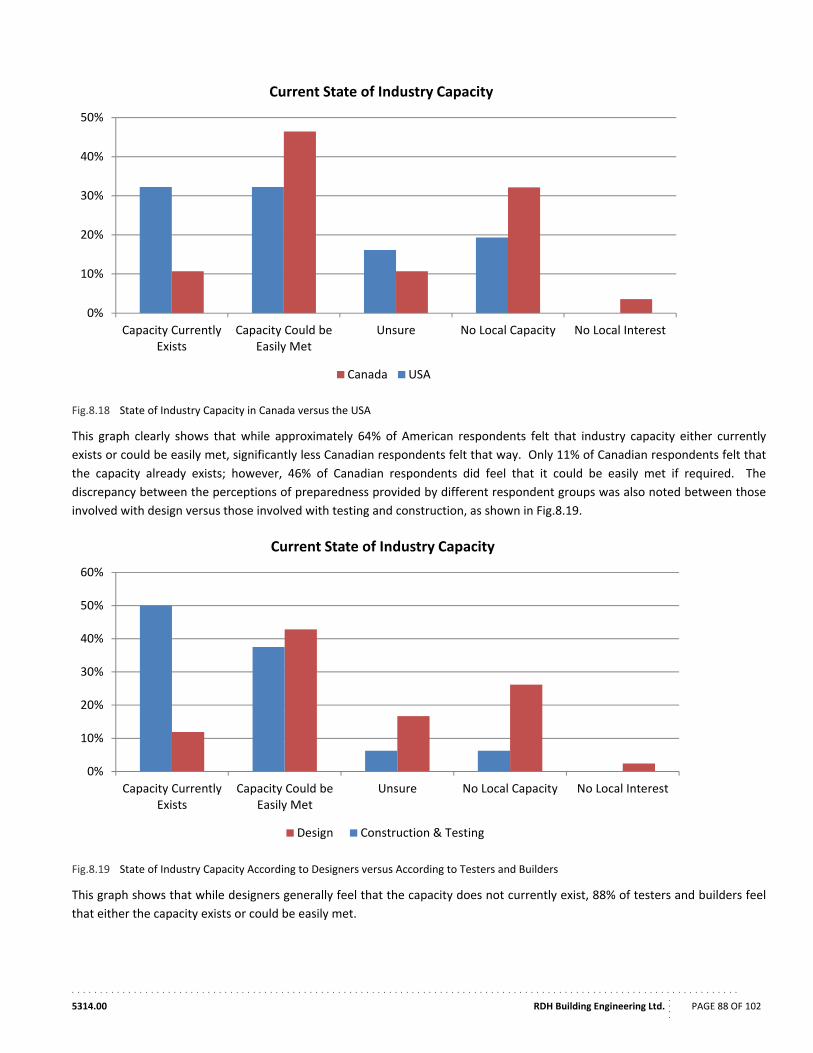
. . . . . . . . . . . . . . . . . . . . . . . . . . . . . . . . . . . . . . . . . . . . . . . . . . . . . . . . . . . . . . . . . . . . . . . . . . . . . . . . . . . . . . . . . . . . . . . . . . . . . . . . . . . . . . . . . . . . . .
5314.00 RDH Building Engineering Ltd.
....
PAGE 88 OF 102
Fig.8.18 State of Industry Capacity in Canada versus the USA
This graph clearly shows that while approximately 64% of American respondents felt that industry capacity either currently
exists or could be easily met, significantly less Canadian respondents felt that way. Only 11% of Canadian respondents felt that
the capacity already exists; however, 46% of Canadian respondents did feel that it could be easily met if required. The
discrepancy between the perceptions of preparedness provided by different respondent groups was also noted between those
involved with design versus those involved with testing and construction, as shown in Fig.8.19.
Fig.8.19 State of Industry Capacity According to Designers versus According to Testers and Builders
This graph shows that while designers generally feel that the capacity does not currently exist, 88% of testers and builders feel
that either the capacity exists or could be easily met.
0%
10%
20%
30%
40%
50%
No Local InterestNo Local CapacityUnsureCapacity Could beEasily Met
Capacity CurrentlyExists
Current State of Industry Capacity
Canada USA
0%
10%
20%
30%
40%
50%
60%
No Local InterestNo Local CapacityUnsureCapacity Could beEasily Met
Capacity CurrentlyExists
Current State of Industry Capacity
Design Construction & Testing
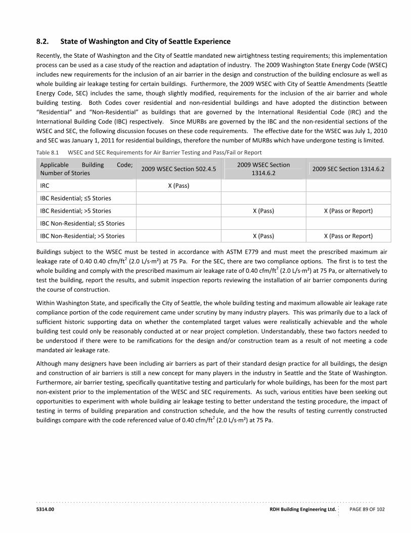
. . . . . . . . . . . . . . . . . . . . . . . . . . . . . . . . . . . . . . . . . . . . . . . . . . . . . . . . . . . . . . . . . . . . . . . . . . . . . . . . . . . . . . . . . . . . . . . . . . . . . . . . . . . . . . . . . . . . . .
5314.00 RDH Building Engineering Ltd.
....
PAGE 89 OF 102
8.2. State of Washington and City of Seattle Experience
Recently, the State of Washington and the City of Seattle mandated new airtightness testing requirements; this implementation
process can be used as a case study of the reaction and adaptation of industry. The 2009 Washington State Energy Code (WSEC)
includes new requirements for the inclusion of an air barrier in the design and construction of the building enclosure as well as
whole building air leakage testing for certain buildings. Furthermore, the 2009 WSEC with City of Seattle Amendments (Seattle
Energy Code, SEC) includes the same, though slightly modified, requirements for the inclusion of the air barrier and whole
building testing. Both Codes cover residential and non‐residential buildings and have adopted the distinction between
“Residential” and “Non‐Residential” as buildings that are governed by the International Residential Code (IRC) and the
International Building Code (IBC) respectively. Since MURBs are governed by the IBC and the non‐residential sections of the
WSEC and SEC, the following discussion focuses on these code requirements. The effective date for the WSEC was July 1, 2010
and SEC was January 1, 2011 for residential buildings, therefore the number of MURBs which have undergone testing is limited.
Table 8.1 WSEC and SEC Requirements for Air Barrier Testing and Pass/Fail or Report
Applicable Building Code; Number of Stories
2009 WSEC Section 502.4.5 2009 WSEC Section
1314.6.2 2009 SEC Section 1314.6.2
IRC X (Pass)
IBC Residential; ≤5 Stories
IBC Residential; >5 Stories X (Pass) X (Pass or Report)
IBC Non‐Residential; ≤5 Stories
IBC Non‐Residential; >5 Stories X (Pass) X (Pass or Report)
Buildings subject to the WSEC must be tested in accordance with ASTM E779 and must meet the prescribed maximum air
leakage rate of 0.40 0.40 cfm/ft2 (2.0 L/s∙m²) at 75 Pa. For the SEC, there are two compliance options. The first is to test the
whole building and comply with the prescribed maximum air leakage rate of 0.40 cfm/ft2 (2.0 L/s∙m²) at 75 Pa, or alternatively to
test the building, report the results, and submit inspection reports reviewing the installation of air barrier components during
the course of construction.
Within Washington State, and specifically the City of Seattle, the whole building testing and maximum allowable air leakage rate
compliance portion of the code requirement came under scrutiny by many industry players. This was primarily due to a lack of
sufficient historic supporting data on whether the contemplated target values were realistically achievable and the whole
building test could only be reasonably conducted at or near project completion. Understandably, these two factors needed to
be understood if there were to be ramifications for the design and/or construction team as a result of not meeting a code
mandated air leakage rate.
Although many designers have been including air barriers as part of their standard design practice for all buildings, the design
and construction of air barriers is still a new concept for many players in the industry in Seattle and the State of Washington.
Furthermore, air barrier testing, specifically quantitative testing and particularly for whole buildings, has been for the most part
non‐existent prior to the implementation of the WESC and SEC requirements. As such, various entities have been seeking out
opportunities to experiment with whole building air leakage testing to better understand the testing procedure, the impact of
testing in terms of building preparation and construction schedule, and the how the results of testing currently constructed
buildings compare with the code referenced value of 0.40 cfm/ft2 (2.0 L/s∙m²) at 75 Pa.
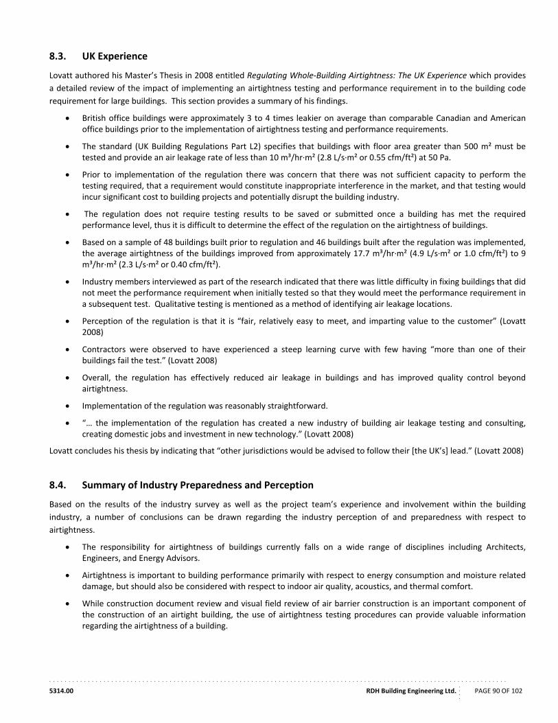
. . . . . . . . . . . . . . . . . . . . . . . . . . . . . . . . . . . . . . . . . . . . . . . . . . . . . . . . . . . . . . . . . . . . . . . . . . . . . . . . . . . . . . . . . . . . . . . . . . . . . . . . . . . . . . . . . . . . . .
5314.00 RDH Building Engineering Ltd.
....
PAGE 90 OF 102
8.3. UK Experience
Lovatt authored his Master’s Thesis in 2008 entitled Regulating Whole‐Building Airtightness: The UK Experience which provides
a detailed review of the impact of implementing an airtightness testing and performance requirement in to the building code
requirement for large buildings. This section provides a summary of his findings.
British office buildings were approximately 3 to 4 times leakier on average than comparable Canadian and American office buildings prior to the implementation of airtightness testing and performance requirements.
The standard (UK Building Regulations Part L2) specifies that buildings with floor area greater than 500 m² must be tested and provide an air leakage rate of less than 10 m³/hr∙m² (2.8 L/s∙m² or 0.55 cfm/ft²) at 50 Pa.
Prior to implementation of the regulation there was concern that there was not sufficient capacity to perform the testing required, that a requirement would constitute inappropriate interference in the market, and that testing would incur significant cost to building projects and potentially disrupt the building industry.
The regulation does not require testing results to be saved or submitted once a building has met the required performance level, thus it is difficult to determine the effect of the regulation on the airtightness of buildings.
Based on a sample of 48 buildings built prior to regulation and 46 buildings built after the regulation was implemented, the average airtightness of the buildings improved from approximately 17.7 m³/hr∙m² (4.9 L/s∙m² or 1.0 cfm/ft²) to 9 m³/hr∙m² (2.3 L/s∙m² or 0.40 cfm/ft²).
Industry members interviewed as part of the research indicated that there was little difficulty in fixing buildings that did not meet the performance requirement when initially tested so that they would meet the performance requirement in a subsequent test. Qualitative testing is mentioned as a method of identifying air leakage locations.
Perception of the regulation is that it is “fair, relatively easy to meet, and imparting value to the customer” (Lovatt 2008)
Contractors were observed to have experienced a steep learning curve with few having “more than one of their buildings fail the test.” (Lovatt 2008)
Overall, the regulation has effectively reduced air leakage in buildings and has improved quality control beyond airtightness.
Implementation of the regulation was reasonably straightforward.
“… the implementation of the regulation has created a new industry of building air leakage testing and consulting, creating domestic jobs and investment in new technology.” (Lovatt 2008)
Lovatt concludes his thesis by indicating that “other jurisdictions would be advised to follow their [the UK’s] lead.” (Lovatt 2008)
8.4. Summary of Industry Preparedness and Perception
Based on the results of the industry survey as well as the project team’s experience and involvement within the building
industry, a number of conclusions can be drawn regarding the industry perception of and preparedness with respect to
airtightness.
The responsibility for airtightness of buildings currently falls on a wide range of disciplines including Architects, Engineers, and Energy Advisors.
Airtightness is important to building performance primarily with respect to energy consumption and moisture related damage, but should also be considered with respect to indoor air quality, acoustics, and thermal comfort.
While construction document review and visual field review of air barrier construction is an important component of the construction of an airtight building, the use of airtightness testing procedures can provide valuable information regarding the airtightness of a building.
. . . . . . . . . . . . . . . . . . . . . . . . . . . . . . . . . . . . . . . . . . . . . . . . . . . . . . . . . . . . . . . . . . . . . . . . . . . . . . . . . . . . . . . . . . . . . . . . . . . . . . . . . . . . . . . . . . . . . .
5314.00 RDH Building Engineering Ltd.
....
PAGE 91 OF 102
Qualitative testing is useful for diagnostics and for the testing of individual complicated details; however, quantitative testing provides the added benefit of providing values that can be compared to baselines, between buildings, as well as to set requirements.
Blower door testing of smaller buildings is common in industry, so much of the equipment for the testing of larger buildings is readily available.
In Canada, there is currently limited capacity to perform airtightness testing; however, many industry participants feel that capacity could be easily developed if it became a requirement. About half of the industry feels that this capacity could be developed in less than two years, while the other half feels it would take longer.
Airtightness requirements including mandatory testing for verification should be implemented in the building code; industry would likely be able to adapt in the next two years to accommodate these new requirements.
Experience with the implementation of airtightness testing and performance requirements in the United Kingdom suggest that
despite a perceived lack of industry capacity and apprehension with respect to the impact on industry, the building industry is
able to adapt remarkably quickly to changes in regulation. Furthermore, the implementation of regulation in that jurisdiction
has led to a significant improvement in airtightness performance. The experience within Washington State has…
These insights into the industry preparedness and perception of airtightness in buildings will help to guide future decision with
respect to the potential implementation of airtightness requirements.
. . . . . . . . . . . . . . . . . . . . . . . . . . . . . . . . . . . . . . . . . . . . . . . . . . . . . . . . . . . . . . . . . . . . . . . . . . . . . . . . . . . . . . . . . . . . . . . . . . . . . . . . . . . . . . . . . . . . . .
5314.00 RDH Building Engineering Ltd.
....
PAGE 92 OF 102
9. Conclusions
The information collected and analysed in this report provides valuable insight in the state of airtightness in the building
industry and in particular with respect the multi‐unit residential buildings.
Airtightness is an important component of building performance. The control of air exfiltration and infiltration through the
exterior building enclosure impacts building energy efficiency, the potential for moisture related damage, interior comfort, and
indoor air quality. Compartmentalization, which is dependent upon airtightness of interior building separators, also provides
important airflow control within buildings. It reduces the magnitude of stack effect forces which can create large sustained
pressure differences that drive airflow in taller buildings. Additionally, compartmentalization can reduce energy consumption
and help to control air contamination, including odours, from transferring between spaces in the building. The combination of
exfiltration and infiltration control with compartmentalization also provides a predictable system for the design of building
ventilation systems which can significantly improve the ability of the system to provide fresh air to spaces and control airflows
within the building.
To provide an airtight building enclosure or to seal interior spaces of a building (i.e., compartmentalize), a variety of systems and
technologies are available and widely implemented on the market. It is important when selecting and designing building air
barriers that adequately robust systems are selected to achieve the airtightness targets and maintain these targets over the
service life of the air barrier systems.
To test the airtightness performance of buildings a variety of techniques have been developed both in Canada and
internationally. These techniques share many similarities. For the testing of MURBs the pressurization or depressurization of
the entire building to perform a test is frequently impractical or impossible, so the application of classical whole building
pressurization and depressurization techniques is not practical. Instead alternative techniques need to be assessed. Based on
the testing techniques reviewed, it is felt the pressure neutralized fan pressurization/depressurization technique is the most
applicable test procedure for MURB airtightness testing at this time.
The balanced fan technique allows for the testing of a smaller space within a MURB in which the test pressures can more
practically be achieved. Additionally, this technique is able to quantify the airtightness characteristics of both the exterior
building enclosure and of interior compartmentalizing elements. Industry familiarity with this technique is somewhat less than
with whole building techniques such as CGSB 149.10 or ASTM E 779; consequently, if the balanced fan
pressurization/depressurization technique were to be used as a standardized procedure, training would need to be provided to
members of industry.
Regardless of the airtightness test method selected, testing of new buildings should be implemented once the air barrier
assemblies are complete but prior to occupation of the building. This limits many of the variables that come with testing an
occupied building and also provides the opportunity to locate and seal any problematic air leakage locations before construction
completion. The implementation of airtightness testing and performance requirements in other jurisdictions has led to
significant improvements in building airtightness. In the UK, this improvement has been documented to be greater than 50%.
Comparable impacts in Canada are anticipated if similar requirements are implemented.
It should be noted that qualitative airtightness testing can also be effective in locating air leakage locations and can be
particularly effective in diagnosing causes of high air leakage rates and identifying areas to be air sealed. These qualitative
techniques including infrared photography and smoke testing should be promoted as effective methods to be used in the
airtightness commissioning of buildings.
As airtightness standards and codes were reviewed for this project, a wide range of metrics were identified to quantify
airtightness. Of the metrics encountered during the review, it was found that the normalized airflow rate in units of litres per
second meter squared (L/s∙m²) at a specific test pressure is most applicable. (The inch‐pound unit alternative is cubic feet per
minute per square foot, cfm/ft², which are the more commonly used units in industry.) The normalized airflow rate is a direct

. . . . . . . . . . . . . . . . . . . . . . . . . . . . . . . . . . . . . . . . . . . . . . . . . . . . . . . . . . . . . . . . . . . . . . . . . . . . . . . . . . . . . . . . . . . . . . . . . . . . . . . . . . . . . . . . . . . . . .
5314.00 RDH Building Engineering Ltd.
....
PAGE 93 OF 102
measure of the permeance of the building enclosure or interior compartmentalizing elements and can be easily compared
between buildings. Alternative measures such as air change rate account for the volume of the space, which can be relevant for
ventilation calculations, but do not provide a fundamental indication of airtightness. Equivalent Leakage Area could potentially
be used as an indicator; however, due to the confusion between Equivalent and Effective Leakage Areas it is practical to select a
less ambiguous form.
The pressure at which measurements were provided also varied widely. Two approaches to the selection of a standard pressure
should be considered. The first is to use a pressure indicative of potential in‐service pressure differentials. Typically either 10
Pa (CGSB) or 4 Pa (ASTM) are used for these values. The second option is to select a pressure at which testing is actually
performed. For use in a standard or code it is felt that the second option is preferable. With the equipment available and the
adoption of a testing technique for compartmentalized sections of larger buildings, creating a pressure difference of 75 Pa
should be possible. This pressure is of sufficient magnitude to largely overcome bias due to the driving forces of wind and stack
effect and thus could potentially be used for a single point test when multi point testing and/or both pressurization and
depressurization testing is not performed. Additionally this value could be obtained with little need for conversion which limits
the potential for error.
The range of airtightness values found in standards and codes is quite large, and varies by a factor of approximately 10;
however, a typical value of 0.40 cfm/ft2 (2.0 L/s∙m²) at 75 Pa has been determined and this is consistent with the current value
used in the Washington State testing standard. This value would provide a good target value for use in codes or standards. A
higher performance target that could still realistic be achieved could be 0.25 cfm/ft² (1.27 m³/s∙m²) at 75 Pa which is the current
USACE requirement. Proposed future USACE requirements are targeting even lower levels, down to 0.15 cfm/ft² (0.76 m³/s∙m²)
at 75 Pa
The responses to the industry survey, primarily from those most likely involved in airtightness of buildings, indicated an
appreciation of the importance of airtightness with respect to building performance and general support for the
implementation of quantitative airtightness targets into building codes. Based on that industry sector feedback provided in the
survey, it is felt the industry could likely achieve capacity for airtightness testing within two years.
. . . . . . . . . . . . . . . . . . . . . . . . . . . . . . . . . . . . . . . . . . . . . . . . . . . . . . . . . . . . . . . . . . . . . . . . . . . . . . . . . . . . . . . . . . . . . . . . . . . . . . . . . . . . . . . . . . . . . .
5314.00 RDH Building Engineering Ltd.
....
PAGE 94 OF 102
10. Acknowledgements
While the project team members were the primary contributors of reference material, testing data, and industry insight for the
completion of this project, numerous other individuals and organizations have contributed by responding to the survey and/or
contributing testing data to the airtightness testing database. In particular, the project team would like to acknowledge the
following people and organizations for their contributions to this project.
Retrotec – Colin Genge
Proskiw Engineering Ltd. – Gary Proskiw
Patenaude‐Trempe Inc. – Mario Gonçalves
Walsh Construction Ltd. – Mike Steffen
NBEC Board
Southern Energy Management – Meghan McDermott
US Army Corp of Engineers
. . . . . . . . . . . . . . . . . . . . . . . . . . . . . . . . . . . . . . . . . . . . . . . . . . . . . . . . . . . . . . . . . . . . . . . . . . . . . . . . . . . . . . . . . . . . . . . . . . . . . . . . . . . . . . . . . . . . . .
5314.00 RDH Building Engineering Ltd.
....
PAGE 95 OF 102
11. References
Air Tightness Testing & Measurement Association. "Technical Standard L1. ‐ Measuring Air Permeability of Building Envelopes
(Dwellings)." Northampton: ATTMA, October 2010.
American Society of Heating, Refrigerating and Air‐Conditioning Engineers, Inc. 2009 ASHRAE Handbook ‐ Fundamentals.
Atlanta: ASHRAE, 2009.
ASHRAE. "ASHRAE Standard 90.1‐2007 Energy Standard for Buildings Except Low‐Rise Residential Buildings." Atlanta: ASHRAE,
2007.
—. "ASHRAE Standard 90.1‐2007 Energy Standard for Buildings Except Low‐Rse Residential Buildings." Atlanta: ASHRAE, 2007.
ASTM. "ASTM Designation E 283‐04 Standard Test Method for Determining Rate of Air Leakage Through Exterior Windows,
Curatin Wall, and Doors Under Specified Pressure Differences Across the Specimen." West Conshohocken: ASTM, 2004.
—. "ASTM Designation E 741‐00 Standard Test Method for Determining Air Change in a Single Zone by Means of a Tracer Gas
Dilution." West Conshohocken: ASTM, 2000.
—. "ASTM Designation: E 1186‐03 Standard Practices for Air Leakage Site Detectin in Building Envelopes and Air Barrier
Systems." West Conhohocken: ASTM, 2003.
—. "ASTM Designation: E 1827‐96 (Reapproved 2007) Standard Test Methods for Determining Airtightness of Buildings Using an
Orifice Blower Door." West Conshohocken: ASTM, 2007.
—. "ASTM Designation: E 783‐02 Standard Test Method for Field Measurement of Air Leakage Through Installed Exterior
Windows and Doors." West Conshohocken: ASTM, n.d.
—. "ASTM Designation: E2357‐05 Standard Test Method for Determining Air Leakage of Air Barrier Assemblies." West
Conshohocken: ASTM, 2005.
—. "ASTM Designation: E779‐10 Standard Test Method for Determinign Leakage Rate by Fan Pressurization." West
Conshohocken: ASTM, 2010.
Bahnfleth, W, Y Grenville, and B Lee. "Protocol for Field Testing of Tall Buildings to Determine Envelope Air Leakage Rate."
(ASHRAE) 105 (1999).
Canada Green Building Council. LEED Canada for Existing Buildings: Operations and Maintenance. Ottawa: Canada Green
Building Council, 2009.
Canadian General Standards Board. "CAN/CGSB‐149.10‐M86." Ottawa: Canadian General Standards Board, 1986.
—. "CAN/CGSB‐149.15‐96 Determination of the Overall Envelope Airtightness of Buildings by the Fan Pressurization Method
Using the Building's Air Handling Systems." Ottawa: Canadian General Standards Board, March 1996.
Colliver, D, and W Murphy. Evaluation of the Techniques for the Measurement of Air Leakage of Building Components. Atlanta:
American Society of Heating, Refrigerating, and Air‐Conditioning Engineers Inc., 1992.
DePani, S, and P Fazio. "Airtightness Testing and Air Flow Modelling of Two and Three‐Unit Multifamily Building." eSim 2011:
Canadian Conference on Building Energy Simulation. Ottawa, 2001.
Energy Star. "Energy Star Multifamily High Rise National Prescriptive Path Requirements, Version 1.0." US Environmental
Protection Agency, June 2011.
. . . . . . . . . . . . . . . . . . . . . . . . . . . . . . . . . . . . . . . . . . . . . . . . . . . . . . . . . . . . . . . . . . . . . . . . . . . . . . . . . . . . . . . . . . . . . . . . . . . . . . . . . . . . . . . . . . . . . .
5314.00 RDH Building Engineering Ltd.
....
PAGE 96 OF 102
—. "Testing and Verification Protocols." US Environmental Protection Agency, June 2011.
Finch, G. The Performance of Rainscreen Walls in Coastal British Columbia. Masters Thesis, Waterloo: University of Waterloo,
2007.
Gonçalves, Mario, Pierre Gendron, and Tony Colantonio. "Commissioning of Exterior Building Envelopes of Large Buildings for
Air Leakage and Resultant Moisture Accumulation using Infrared Thermography and Other Diagnostic Tools." Thermal
Solutions 2007. Sarasota: Thermal Solutions 2007, 2007.
International Organization for Standards. "International Standard ISO 9972 Thermal performance of buildings ‐ Determination of
air permeability of buildings ‐ Fan pressurization method." Geneva: ISO, 2006.
LEED Canada. LEED Canada for New Construction and Major Renovations 2009. Ottawa: Canada Green Building Council, 2009.
Lovatt, J. Regulating Whole‐Building Airtightness: The UK Experience. Masters Thesis, London: London Metropolitan University,
2008.
Lstiburek, J. Toward an Understanding and Prediction of Air Flow in Buildings. PhD Thesis, Toronto: University of Toronto, 2000.
Natural Resources Canada. Survey of Household Energy Use 2007. Ottawa: Natural Resources Canada, 2007.
Proskiw, G, and A Parekh. "A Proposed Test Procedure for Separating Exterior Envelope Air Leakage from interior Partition Air
Leakage." Conference Proceedings ‐ Performance of Exterior Envelopes of Whole Buildings VIII. Atlanta: American
Society of Heating, Refrigerating and Air‐Conditioning Engineers Inc, 2001. 1‐7.
Proskiw, G, and B Phillips. "An Examination of Air Pressure and Air Movement Patterns in Multi‐Unit Residential Buildings."
2006.
Proskiw, G., and B Phillips. Air Leakage Characteristics, Test Methods, and Specifications for Large Buildings. Ottawa: Canada
Mortgage and Housing Corporation, 2001.
Proskiw, G., and B Phillips. Air Leakage Characteristics, Test Methods, and Specifications for Large Buildings. Ottawa: Canada
Mortgage and Housing Corporation, 2001.
Retrotec Inc. Residential Pressure & Air Leakage Manual. Everson: Retrotec, 2012.
Retrotec. Residential and Commercial Airtightness Requirements. Vancouver: Retrotec, 2012.
Retrotec. Residential Pressure and Air Leakage Testing Manual. Everson: Retrotec, 2012.
Tamura, G.T., and C.Y. Shaw. "Studies on Exterior Wall Air Tightness and Air Infiltration of Tall Buildings." ASHRAE Transactions
(National Research Council of Canada), 1976: 122‐134.
U.S. Army Corps of Engineers. Air Leakage Test Protocol for Measuring Air Leakage of Buildings. Champaign: U.S. Army Corps of
Engineers, 2010.
US Army Corps of Engineer and Air Barrier Association of America. U.S. Army Corps of Engineers Air Leakage Test Protocol for
Building Envelopes. Champaign: U.S. Army Corps of Engineers, 2011.
. . . . . . . . . . . . . . . . . . . . . . . . . . . . . . . . . . . . . . . . . . . . . . . . . . . . . . . . . . . . . . . . . . . . . . . . . . . . . . . . . . . . . . . . . . . . . . . . . . . . . . . . . . . . . . . . . . . . . .
5314.00 RDH Building Engineering Ltd.
....
PAGE 97 OF 102
12. Bibliography
2009 Seattle Energy Code. Seattle: Seattle Department of Planning and Development, 2010.
Air Tightness Testing & Measurement Association. "Technical Standard L1. ‐ Measuring Air Permeability of Building Envelopes
(Dwellings)." Northampton: ATTMA, October 2010.
AIVC. AIVC Newsletter, Dember 2011: 1‐4.
Brennan, T, and M Clarkin. "Characterizing Air Leakage in Large Buildings: Part I." Journal of Building Enclosure Design, 2007: 41‐
44.
Brennan, T, and M Clarkin. "Characterizing Air Leakage in Large Buildings: Part II." Journal of Building Enclosure Design, 2008: 32‐
34.
Brennan, T, and S Emmerich. "Measuring Airtightness at ASHRAE Headquarters." ASHRAE Journal, 2007: 26‐28.
Buchan Lawton Parent Ltd. Research Highlight: Evaluation of Air Leakage Control Measures to Compartmentalize Newly
Constructed Suites in A High‐Rise Residential Building. Ottawa: CMHC, 2006.
Buchberg, B, and J Ananian. "Quality Control of Air Barriers During Construction." n.d.
David C. Stewart & Associates Inc. Research Highlight ‐ Performance Evaluation of the Almon Street Multi‐Unit Residential
Building. Ottawa: CMHC, 2006.
DePani, S, and P Fazio. "Airtightness Testing and Air Flow Modelling of a Three‐Unit Multifamily Building." n.d.
Dumont and Associates. Report on the Whole Building Air Leakage Test at the Ecole Ste. Anne. Saskatoon: Dumon and
Associates, 2011.
Dumont, R. Air Tightness Testing of Phases 1 and 2 of the Warman High School Addition. Saskatoon: Saskatchewan Research
Council, 2006.
Dumont, R. Air Tightness Testing of the Centruy Plaza Building Redevelopment Project in Regina. Saskatoon: Saskatchewan
Research Council, 2006.
Emmerich, S, A Persily, and T McDowell. Imapct of Commercial Building Infiltration on Heating and Cooling Loads in U.S. Office
Buildings. Brussels: AIVC, 2005.
Emmerich, S, and A Persily. Airtightness of Commercial Buildings in the U.S. Gaithersburg: Building and Fire Research Laboratory,
National Institute of Standards and Technology, n.d.
Energy Star. "Testing and Verification Protocols." US Environmental Protection Agency, June 2011.
Finch, G, J Straube, and C Genge. "Air Leakge Within Multi‐Unit Residential Buildings: Testing and Implications for Building
Performance." Proceedings of 12th Canadian Conference on Building Science and Technology. Montreal: National
Building Envelope Council, 2009. 529‐544.
Genge, C. Modernizing ISO, EN and ASTM Air Leakage Standards. Everson: Retrotec, 2011.
Hamlin, T, and J Gusdorf. Airtightness and Energy Efficiency of New Conventional and R‐2000 Housing in Canada. Ottawa:
CANMET Energy Technology Centre, Energy Technology Branch, Energy Sector, Department of Natural Resources
Canada, 1997.
. . . . . . . . . . . . . . . . . . . . . . . . . . . . . . . . . . . . . . . . . . . . . . . . . . . . . . . . . . . . . . . . . . . . . . . . . . . . . . . . . . . . . . . . . . . . . . . . . . . . . . . . . . . . . . . . . . . . . .
5314.00 RDH Building Engineering Ltd.
....
PAGE 98 OF 102
Lilly, J. "Ventilation and Leakage Measurements in Industrial Buildings." Ventilation Technology ‐ Research and Application 8th
AIVC Conference, Uberlingen, Federal Republic of Germany. Uberlingen: AIVC, 1987. 18.1‐18.10.
Limb, M. Ventilation and Building Airtightness: an International Comparison of Standards, Codes of Practice and Regulations.
Technical Note AIVC 43, Coventry: AIVC, 1994.
Litvak, Andres, Didier Boze, and Marc Kilberger. "Airtightness of 12 Non Residential Large Buildings results from Field
Measurement Studies." n.d.
Lstiburek, J. "Air Pressure and Building Envelopes." n.d.
Lstiburek, J. Insight: Just Right and Airtight. buildingscience.com, 2011.
Parekh, A, K Ruest, and M Jacobs. "Comparison of Airtightness, Indoor Air Quality and Power Consumption Before and After Air‐
Sealing of High‐Rise Residential Buildings." 12th AIVC Conference. Ottawa: AIVC, 1991. 315‐321.
Patenaude‐Trempe Inc. Summary of a Research Project ‐ Air Leakage Testing in MURBs. Montreal: Patenaude‐Trempe Inc, 2011.
Proskiw, G. Air Leakage Examination: Maintenance Building, Dorsey Converter Station. Proskiw Engineering Ltd, 2004.
Retrotec. "Large Building Air Leakge Test Results." Vancouver, 2009.
Shaw, C.Y., S Gasparetto, and J.T. Reardon. Methods for Measuring Air Leakage in High‐Rise Apartments. Philadelphia: American
Society for Testing and Materials, 1990.
Sherman, M, and D Dickerhoff. "Air‐Tightness in U.S. Dwellings." The Role of Ventilation ‐ 15th AIVC Conference. Buxton: AIVC,
1994. 226‐234.
Sherman, M, and R Chan. Building Airtightness: Research and Practice. Report No. LBNL‐53356, Berkley: Lawrence Berkley
National Laboratory, 2004.
Steffen, M. "Towards Airtightness ‐ The Contractor's Role in Designing and Constructing the Air Barrier System." n.d.
Tamura, G, and C Shaw. Studies on Exterior Wall Air Tightness and Air Infiltration of Tall Buildings. Ottawa: National Research
Council of Canada, 1976.
Washington State Energy Code ‐ 2009 Edition. Olympia: Washington State Building Code Council, 2011.
Yilmaz, Veysel, and H Celik. A Statistical Approach to Estimate the Wind Speed Distribution: The Case of Gelibolu Geion. Istanbul:
Dogus Universitesi Dergisi, 2008.
. . . . . . . . . . . . . . . . . . . . . . . . . . . . . . . . . . . . . . . . . . . . . . . . . . . . . . . . . . . . . . . . . . . . . . . . . . . . . . . . . . . . . . . . . . . . . . . . . . . . . . . . . . . . . . . . . . . . . .
5314.00 RDH Building Engineering Ltd.
....
PAGE 99 OF 102
13. Glossary of Terms
air barrier Refers to the materials and components of the building enclosure or of compartmentalizing elements that together control airflow through the assembly.
air changes per hour (ACH)
Refers to the number of times per hour that a volume of air (room, suite, etc) is replaced in an hour. Provides an indication of ventilation rates.
air leakage Refers to air which unintentionally flows through building enclosure or compartmentalizing elements. This is often quantified as Normalized Leakage Rate [cfm/ft² or L/s∙m²] or simply Leakage Rate [cfm or L/s].
airtightness Refers to the ability of building enclosure or compartmentalizing element to resist airflow. A system which is more airtight has higher resistance to airflow. This is often quantified as Normalized Leakage Rate [cfm/ft² or L/s∙m²] or simply Leakage Rate [cfm or L/s].
ASHRAE American Society of Heating, Refrigerating and Air‐Conditioning Engineers
ASTM American Society for Testing and Materials (ASTM)
ATTMA Airtightness Testing and Measurement Association
airflow Refers to the movement of air from one space to another. Usually measure in cfm or L/s at a specific reference pressure.
baseline pressure Refers to the pressure difference measured between the exterior and interior of the building when no fans are used to adjust the pressure. Baseline pressure is caused by the natural driving forces of stack effect and wind.
below‐grade Refers to the portion of the building that is below the level of the ground surface.
bias pressure See “baseline pressure”
blower Refers to a large fan.
blower door See “fan‐door”
building enclosure Refers to the part of a building which separates the interior environmental conditions from the exterior environmental conditions including the control of precipitation, water vapour, air, and heat.
condensation Refers to the change in state of water from vapour to liquid. Often materializes as water on a surface that is below the dewpoint temperature of the air.
condominium Refers to a multi‐unit residential building in which each unit is individually owned and the common areas are jointly owned.
cfm cubic feet per minute (ft³/min)
CGSB Canadian General Standards Board
compartmentalization Refers to separating a single building volume (floor, room, suite, office, etc) within a larger building volume with the primary intention of controlling airflows into and out of the space. Compartmentalization is typically performed for fire, smoke, odours, and acoustic separation; however, it can also be important for HVAC control.
compartmentalizing elements
Refers to any interior element of the building that is intentionally designed to limit the flow of air between adjacent spaces. Typically this would include walls between suites, walls between suites and the corridor, and floors.
. . . . . . . . . . . . . . . . . . . . . . . . . . . . . . . . . . . . . . . . . . . . . . . . . . . . . . . . . . . . . . . . . . . . . . . . . . . . . . . . . . . . . . . . . . . . . . . . . . . . . . . . . . . . . . . . . . . . . .
5314.00 RDH Building Engineering Ltd.
....
PAGE 100 OF 102
depressurization Refers to the process of creating negative pressure inside a building or space relative to the surrounding conditions by removing air from the space with a fan.
dewpoint Refers to the temperature at which the air would be saturated with water vapour (100% RH)
driving forces Refers to natural phenomena and mechanical systems which create pressure differentials and thus create airflow. Includes stack effect, wind, and ventilation equipment. Refer to Section 2.2.
effective leakage area (EfLA)
Refers to represents the size of an orifice which would produce the same net air flow at a given pressure differentials as would occur cumulatively through all leakage paths in the building enclosure. Calculated according to ASTM E779, it usually uses a pressure differential of 4Pa and a discharge coefficient of 1.0. See Section 3.1.5.
equivalent leakage area (EqLA)
Refers to represents the size of an orifice which would produce the same net air flow at a given pressure differentials as would occur cumulatively through all leakage paths in the building enclosure. Calculated according to CGSB 149.10, it usually uses a reference pressure of 10Pa and a discharge coefficient of 0.61. See Section 3.1.4.
exhaust air Refers to air which is removed from a space by a mechanical system (fan) as part of the ventilation strategy.
fan‐door Refers to a system which incorporates a door cover and a calibrated blower fan into a system made specifically for installation in a doorway. This system is commonly used in the testing of detached houses and is gaining popularity for use in the testing of larger buildings by using multiple fan‐door systems. See Section 5.6.2.
HVAC Heating, Ventilation, and Air Conditioning. Refers to the equipment used to condition the interior spaces of a building.
IBC International Building Code
IECC International Green Construction Code
IGCC International Green Construction Code
infrared Refers to the spectrum of light with longer wavelengths than visible light (750 nm to 1 nm). Infrared radiation (light) is emitted by objects and is an indicator of surface temperature so can be used in building investigations to identify temperature anomalies on building surfaces.
IRC International Residential Code for One‐ and Two‐ Family Dwellings
ISO International Organization for Standardization
LEED Leadership in Energy and Environmental Design
leakage rate Refers to the rate at which air unintentionally flows through
MURB Multi‐unit Residential Building
NBCC National Building Code of Canada
NECB National Energy Code for Buildings
normalized airflow rate Refers to the airflow rate divided by the relevant enclosure area. Usually measured in units of L/s∙m² at a given pressure differential.
normalized leakage area (NLA)
See “Specific Leakage Area”
pascal (Pa) Is a metric unit of measure for pressure. 1 in H2O = 249 Pa
permeability (air) Is a material property measuring the ability of that material to allow airflow through it. Usually measured in cfm/ft² or L/s∙m² at a given pressure difference.
. . . . . . . . . . . . . . . . . . . . . . . . . . . . . . . . . . . . . . . . . . . . . . . . . . . . . . . . . . . . . . . . . . . . . . . . . . . . . . . . . . . . . . . . . . . . . . . . . . . . . . . . . . . . . . . . . . . . . .
5314.00 RDH Building Engineering Ltd.
....
PAGE 101 OF 102
101permeance (air) Is an enclosure system property measuring the ability of the system to allow airflow through it. This term is essentially the opposite of airtightness. Higher permeance means less airtight. Usually measured in cfm/ft² or L/s∙m² at a given pressure difference.
pressurization Refers to the process of creating positive pressure inside a building or space relative to the surrounding conditions by removing air from the space with a fan.
reference pressure Refers to the pressure differential which is used for a test or the calculation of a quantity. 4 Pa and 10 Pa are commonly used as representative in‐service reference pressures while 50 Pa and 75 Pa are common reference pressures used in testing.
relative humidity (RH) Refers to the proportion of the moisture in the air compared to the amount of moisture the air could potentially hold at that temperature.
specific leakage area (SLA) Refers to either the equivalent or effective leakage area normalized by dividing by the
relevant enclosure area (similar to normalized airflow rate). Just as it is important to
distinguish between EfLA and EqLA, it is also important to distinguish which of these
quantities was used to calculate the SLA. For clarity, it is often convenient to refer to
SLA as the Normalized Equivalent or Effective Leakage Area (as is appropriate) so that
the distinction can be clearly made. See Section 3.1.6.
stack effect Refers to the natural pressure differentials that are developed across the building enclosure as a result of buoyancy forces due to difference in temperature between the interior and exterior of a building. See Section 2.2.2.
supply air Refers to air which provided to a space by a mechanical system (fan) as part of the ventilation strategy.
time averaging Refers to the technique of taking multiple measurements at set intervals over a period of time and then averaging these measurements to obtain a more stable measurement.
tracer gas Refers to gasses which are generally found at low concentration naturally and are not
produced by respiration or by common processes found in buildings and thus can be
used to indicate air flow. Generally, tracer gas use requires the release of the gas in to a
space and the measurement of concentrations of the gas in the space and adjacent
spaces over a period of time. See Sections 5.1.7 and 5.6.6.
USACE United States Army Corps of Engineers
ventilation Refers to the supply and exhaust of air from spaces to maintain indoor air quality by diluting and extracting contaminates.
. . . . . . . . . . . . . . . . . . . . . . . . . . . . . . . . . . . . . . . . . . . . . . . . . . . . . . . . . . . . . . . . . . . . . . . . . . . . . . . . . . . . . . . . . . . . . . . . . . . . . . . . . . . . . . . . . . . . . .
5314.00 RDH Building Engineering Ltd.
....
PAGE 102 OF 102
RDH Building Engineering Ltd.
Lorne Ricketts, EIT
Graham Finch, MASc, P.Eng
Robert Bombino, MSc, PE
Appendix A
MURB Airtigh
tness D
atabase
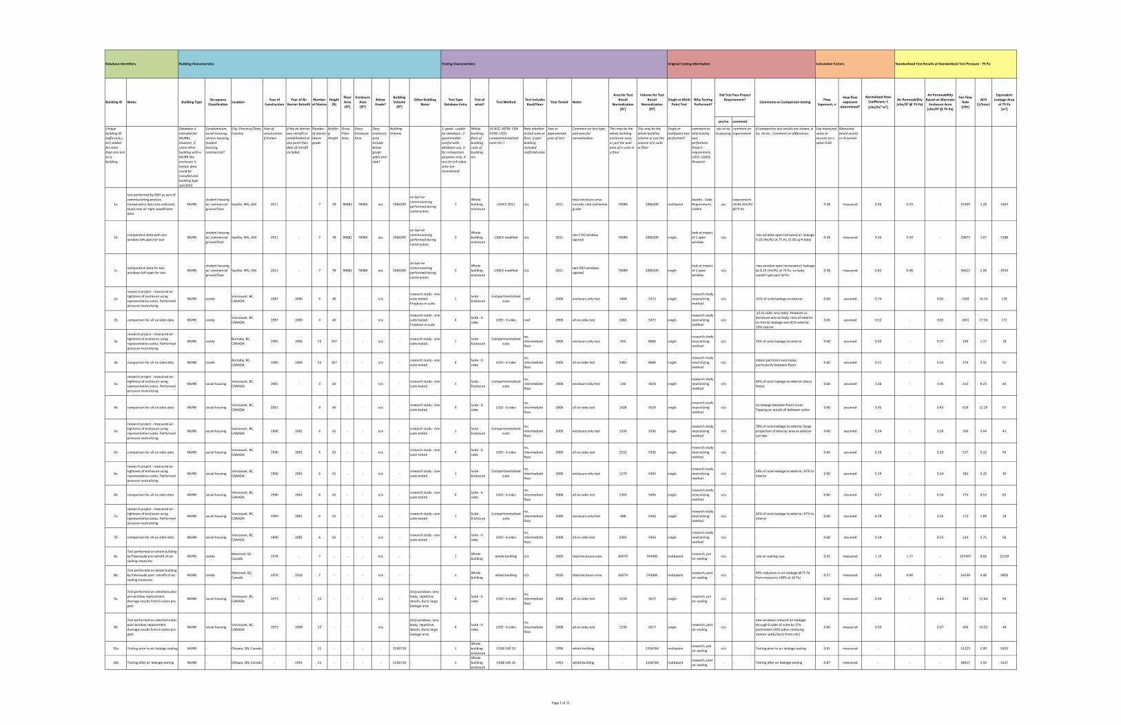
yes/no comment
Unique
building ID.
Suffix (a,b,c,
etc) added
for more
than one test
on a
building.
Database is
intended for
MURBs;
however, if
some other
building with a
MURB like
enclosure is
tested, data
could be
included and
building type
specified.
Condominium,
social housing,
seniors housing,
student
housing,
commercial?
City, Province/State,
Country
Year of
construction
if known
If the air‐barrier
was retrofit or
rehabilitated at
any point then
date of retrofit
included.
Number
of stories
above
grade
Buildin
g
Height
Gross
Floor
Area
Gross
Enclosure
Area
Does
enclosure
area
include
below
grade
walls and
slab?
Building
Volume
1‐ good ‐ usable
for database , 2‐
questionable ‐
careful with
database use, 3‐
for comparison
purposes only, 4‐
test for a 6 sided
suite (un‐
neutralized)
Whole
building,
floor of
building,
suite of
building
etc.
US ACE, ASTM, CAN
CGSB, LEED,
compartmentalized
suite etc.?
Note whether
tested suite or
floor, if part
building
included
roof/slab area
Year or
approximate
year of test
Comment on test type
and area for
normalization
This may be the
whole building
enclosure area,
or just the wall
area of a suite or
a floor
This may be the
whole building
volume or just the
volume of a suite
or floor
Single or
multipoint test
performed?
comment on
why testing
was
performed.
Project
requirement,
LEED, USACE,
Research
yes or no
to passing
comment on
requirement
if comparitive test results are shown, ie
1a, 1b etc.. Comment on differences.
Use measured
value or
assume an n
value 0.60.
Measured
(multi‐point)
or Assumed
1a
test performed by RDH as part of
commissioning process.
Comparative data also collected.
Good new air‐tight woodframe
data
MURB
student housing
w/ commercial
ground floor
Seattle, WA, USA 2011 ‐ 7 78 96882 76084 yes 1066200
air barrier
commissioning
performed during
construction
1
Whole
building
enclosure
USACE 2011 n/a 2011
total enclosure area
includes slab and below
grade
76084 1066200 multipoint
Seattle ‐ Code
Requirement,
USACE
yes
requirement
<0.40 cfm/ft2
@75 Pa
‐ 0.58 measured 0.26 0.29 ‐ 22369 1.26 2403
1bcomparative data with one
window left open for testMURB
student housing
w/ commercial
ground floor
Seattle, WA, USA 2011 ‐ 7 78 96882 76084 yes 1066200
air barrier
commissioning
performed during
construction
3
Whole
building
enclosure
USACE modified n/a 2011one 5 ft2 window
opened76084 1066200 single
look at impact
of 1 open
window
n/a ‐ one window open increased air leakage
0.10 cfm/ft2 at 75 Pa, (5.56 sq ft hole) 0.58 measured 0.34 0.39 ‐ 29673 1.67 3188
1ccomparative data for two
windows left open for testMURB
student housing
w/ commercial
ground floor
Seattle, WA, USA 2011 ‐ 7 78 96882 76084 yes 1066200
air barrier
commissioning
performed during
construction
3
Whole
building
enclosure
USACE modified n/a 2011two 5ft2 windows
opened76084 1066200 single
look at impact
of 2 open
window
n/a ‐
two window open increased air leakage
by 0.19 cfm/ft2 at 75 Pa. so leaky
couldn't get past 50 Pa
0.58 measured 0.42 0.48 ‐ 36622 2.06 3934
2a
research project ‐ measured air‐
tightness of enclosure using
representative suites. Performed
pressure neutralizing
MURB condoVancouver, BC,
CANADA1987 2000 4 40 ‐ ‐ n/a ‐
research study ‐ one
suite tested.
Fireplace in suite
1Suite ‐
Enclosure
Compartmentalized
suiteroof 2006 enclosure only test 1404 5472 single
research study
neutralizing
method
n/a ‐ 81% of suite leakage to exterior 0.60 assumed 0.74 ‐ 0.92 1289 14.14 139
2b comparison for all six sides data MURB condoVancouver, BC,
CANADA1987 2000 4 40 ‐ ‐ n/a ‐
research study ‐ one
suite tested.
Fireplace in suite
4Suite ‐ 6
sidesLEED ‐ 6 sides roof 2006 all six sides test 2462 5472 single
research study
neutralizing
method
n/a ‐
all six sides very leaky. However as
enclosure was so leaky ratio of exterior
to interior leakage was 81% exterior,
19% interior
0.60 assumed 0.52 ‐ 0.65 1601 17.56 172
3a
research project ‐ measured air‐
tightness of enclosure using
representative suites. Performed
pressure neutralizing
MURB condoBurnaby, BC,
CANADA1985 2006 23 207 ‐ ‐ n/a ‐
research study ‐ one
suite tested1
Suite ‐
Enclosure
Compartmentalized
suite
no,
intermediate
floor
2006 enclosure only test 450 8680 single
research study
neutralizing
method
n/a ‐ 35% of suite leakage to exterior 0.60 assumed 0.30 ‐ 0.37 169 1.17 18
3b comparison for all six sides data MURB condoBurnaby, BC,
CANADA1985 2006 23 207 ‐ ‐ n/a ‐
research study ‐ one
suite tested4
Suite ‐ 6
sidesLEED ‐ 6 sides
no,
intermediate
floor
2006 all six sides test 3381 8680 single
research study
neutralizing
method
n/a ‐indoor partitions very leaky,
particularily between floors0.60 assumed 0.11 ‐ 0.14 479 3.31 51
4a
research project ‐ measured air‐
tightness of enclosure using
representative suites. Performed
pressure neutralizing
MURB social housingVancouver, BC,
CANADA2001 ‐ 4 40 ‐ ‐ n/a ‐
research study ‐ one
suite tested1
Suite ‐
Enclosure
Compartmentalized
suite
no,
intermediate
floor
2006 enclosure only test 136 3024 single
research study
neutralizing
method
n/a ‐66% of suite leakage to exterior (ducts
likely)0.60 assumed 2.46 ‐ 3.05 415 8.23 45
4b comparison for all six sides data MURB social housingVancouver, BC,
CANADA2001 ‐ 4 40 ‐ ‐ n/a ‐
research study ‐ one
suite tested4
Suite ‐ 6
sidesLEED ‐ 6 sides
no,
intermediate
floor
2006 all six sides test 1428 3024 single
research study
neutralizing
method
n/a ‐no leakage between floors (conc.
Topping on wood) all between suites0.60 assumed 0.35 ‐ 0.43 619 12.29 67
5a
research project ‐ measured air‐
tightness of enclosure using
representative suites. Performed
pressure neutralizing
MURB social housingVancouver, BC,
CANADA1990 2001 6 61 ‐ ‐ n/a ‐
research study ‐ one
suite tested1
Suite ‐
Enclosure
Compartmentalized
suite
no,
intermediate
floor
2006 enclosure only test 1330 5936 single
research study
neutralizing
method
n/a ‐
78% of suite leakage to exterior (large
proportion of exterior area as exterior
corridor
0.60 assumed 0.24 ‐ 0.29 390 3.94 42
5b comparison for all six sides data MURB social housingVancouver, BC,
CANADA1990 2001 6 61 ‐ ‐ n/a ‐
research study ‐ one
suite tested4
Suite ‐ 6
sidesLEED ‐ 6 sides
no,
intermediate
floor
2006 all six sides test 2532 5936 single
research study
neutralizing
method
n/a ‐ ‐ 0.60 assumed 0.16 ‐ 0.20 517 5.22 56
6a
research project ‐ measured air‐
tightness of enclosure using
representative suites. Performed
pressure neutralizing
MURB social housingVancouver, BC,
CANADA1990 2001 6 61 ‐ ‐ n/a ‐
research study ‐ one
suite tested1
Suite ‐
Enclosure
Compartmentalized
suite
no,
intermediate
floor
2006 enclosure only test 1170 5456 single
research study
neutralizing
method
n/a ‐33% of suite leakage to exterior, 67% to
interior0.60 assumed 0.19 ‐ 0.24 282 3.10 30
6b comparison for all six sides data MURB social housingVancouver, BC,
CANADA1990 2001 6 61 ‐ ‐ n/a ‐
research study ‐ one
suite tested4
Suite ‐ 6
sidesLEED ‐ 6 sides
no,
intermediate
floor
2006 all six sides test 2303 5456 single
research study
neutralizing
method
n/a ‐ ‐ 0.60 assumed 0.27 ‐ 0.34 775 8.53 83
7a
research project ‐ measured air‐
tightness of enclosure using
representative suites. Performed
pressure neutralizing
MURB social housingVancouver, BC,
CANADA1990 2001 6 61 ‐ ‐ n/a ‐
research study ‐ one
suite tested1
Suite ‐
Enclosure
Compartmentalized
suite
no,
intermediate
floor
2006 enclosure only test 488 5456 single
research study
neutralizing
method
n/a ‐36% of suite leakage to exterior, 67% to
interior0.60 assumed 0.28 ‐ 0.35 172 1.89 18
7b comparison for all six sides data MURB social housingVancouver, BC,
CANADA1990 2001 6 61 ‐ ‐ n/a ‐
research study ‐ one
suite tested4
Suite ‐ 6
sidesLEED ‐ 6 sides
no,
intermediate
floor
2006 all six sides test 2303 5456 single
research study
neutralizing
method
n/a ‐ ‐ 0.60 assumed 0.18 ‐ 0.23 523 5.75 56
8a
Test performed on whole building
by Patenaude pre retrofit of air‐
sealing measures
MURB condoMontreal, QC,
Canada1978 ‐ 7 ‐ ‐ ‐ n/a ‐ ‐ 1
Whole
buildingwhole building n/a 2009 total enclosure area 60579 744385 multipoint
research, pre
air‐sealingn/a ‐ pre air sealing case 0.65 measured 1.15 1.77 ‐ 107407 8.66 11539
8b
Test performed on whole building
by Patenaude post retrofit of air‐
sealing measures
MURB condoMontreal, QC,
Canada1978 2010 7 ‐ ‐ ‐ n/a ‐ ‐ 1
Whole
buildingwhole building n/a 2010 total enclosure area 60579 744385 multipoint
research, post
air‐sealingn/a ‐
49% reduction in air‐leakage @75 Pa
from measures, (40% at 10 Pa)0.57 measured 0.83 0.90 ‐ 54539 4.40 5859
9a
Test performed on selected suites
pre‐window replacement.
Average results from 6 suites pre‐
post
MURB social housingVancouver, BC,
CANADA1973 ‐ 22 ‐ ‐ ‐ n/a ‐
strip windows, very
leaky, repetitive
details, ducts large
leakage area
4Suite ‐ 6
sidesLEED ‐ 6 sides
no,
intermediate
floor
2008 all six sides test 1230 2617 singleresearch, pre
air‐sealingn/a ‐ ‐ 0.60 measured 0.36 ‐ 0.44 543 12.44 58
9b
Test performed on selected suites
post‐window replacement.
Average results from 6 suites pre‐
post
MURB social housingVancouver, BC,
CANADA1973 2008 22 ‐ ‐ ‐ n/a ‐
strip windows, very
leaky, repetitive
details, ducts large
leakage area
4Suite ‐ 6
sidesLEED ‐ 6 sides
no,
intermediate
floor
2008 all six sides test 1230 2617 singleresearch, post
air‐sealingn/a ‐
new windows reduced air‐leakage
through 6 sides of suite by 17%
(estimated >50% when removing
interior walls/ducts from calc)
0.60 measured 0.30 ‐ 0.37 450 10.32 48
10a Testing prior to air leakage sealing MURB ‐ Ottawa, ON, Canada ‐ ‐ 21 ‐ ‐ ‐ ‐ 1536718 ‐ 1
Whole
building
enclosure
CGSB 149.10 ‐ 1990 whole building ‐ 1536764 multipointresearch, pre
air‐sealingn/a ‐ Testing prior to air leakage sealing 0.81 measured ‐ ‐ ‐ 51223 2.00 5503
10b Testing after air leakage sealing MURB ‐ Ottawa, ON, Canada ‐ 1991 21 ‐ ‐ ‐ ‐ 1536718 ‐ 1
Whole
building
enclosure
CGSB 149.10 ‐ 1991 whole building ‐ 1536764 multipointresearch, post
air‐sealing‐ ‐ Testing after air leakage sealing 0.87 measured ‐ ‐ ‐ 38417 1.50 4127
How flow
exponent
determined?
Normalized Flow
Coefficient, C
[cfm/Pan∙m²]
Air Permeablility
[cfm/ft² @ 75 Pa]
Equivalent
Leakage Area
at 75 Pa
[in²]
Calculation FactorsOriginal Testing informationTesting Characteristics
Test Includes
Roof/FloorYear Tested Notes
Building CharacteristicsDatabase Identifiers
Building ID Notes Building TypeOccupancy
ClassificationLocation
Year of
Construction
Year of Air
Barrier Retrofit
Number
of Stories
Height
[ft]
Floor
Area
[ft²]
Enclosure
Area
[ft²]
Below
Grade?
Building
Volume
[ft³]
Other Building
Notes
Test Type
Database Entry
Test of
what?Test Method
Standardized Test Results at Standardized Test Pressure ‐ 75 Pa
Area for Test
Result
Normalization
[ft²]
Volume for Test
Result
Normalization
[ft³]
Comments on Comparison testingWhy Testing
Performed?
Single or Multi
Point Test
Flow
Exponent, n
Did Test Pass Project
Requirement?
Air Permeablility
Based on Alternate
Enclosure Area
[cfm/ft² @ 75 Pa]
Fan Flow
Rate
[cfm]
ACH
[1/hour]
Page 1 of 11
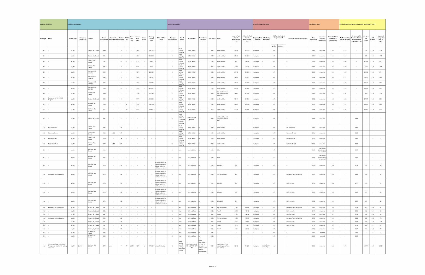
yes/no comment
How flow
exponent
determined?
Normalized Flow
Coefficient, C
[cfm/Pan∙m²]
Air Permeablility
[cfm/ft² @ 75 Pa]
Equivalent
Leakage Area
at 75 Pa
[in²]
Calculation FactorsOriginal Testing informationTesting Characteristics
Test Includes
Roof/FloorYear Tested Notes
Building CharacteristicsDatabase Identifiers
Building ID Notes Building TypeOccupancy
ClassificationLocation
Year of
Construction
Year of Air
Barrier Retrofit
Number
of Stories
Height
[ft]
Floor
Area
[ft²]
Enclosure
Area
[ft²]
Below
Grade?
Building
Volume
[ft³]
Other Building
Notes
Test Type
Database Entry
Test of
what?Test Method
Standardized Test Results at Standardized Test Pressure ‐ 75 Pa
Area for Test
Result
Normalization
[ft²]
Volume for Test
Result
Normalization
[ft³]
Comments on Comparison testingWhy Testing
Performed?
Single or Multi
Point Test
Flow
Exponent, n
Did Test Pass Project
Requirement?
Air Permeablility
Based on Alternate
Enclosure Area
[cfm/ft² @ 75 Pa]
Fan Flow
Rate
[cfm]
ACH
[1/hour]
11 ‐ MURB ‐ Ottawa, ON, Canada 1990 4 ‐ ‐ 15166 ‐ 133772 ‐ 1
Whole
building
enclosure
CGSB 149.10 ‐ 1995 whole building 15166 133776 multipoint ‐ n/a ‐ ‐ 0.62 measured 0.30 0.41 ‐ 6243 2.80 671
12 ‐ MURB ‐ Ottawa, ON, Canada 1991 4 ‐ ‐ 20656 ‐ 226296 ‐ 1
Whole
building
enclosure
CGSB 149.10 ‐ 1995 whole building 20656 226296 multipoint ‐ n/a ‐ ‐ 0.74 measured 0.20 0.44 ‐ 9052 2.40 972
13 ‐ MURB ‐Toronto, ON,
Canada1991 4 ‐ ‐ 32313 ‐ 366037 ‐ 1
Whole
building
enclosure
CGSB 149.10 ‐ 1995 whole building 32313 366037 multipoint ‐ n/a ‐ ‐ 0.83 measured 0.20 0.68 ‐ 21962 3.60 2359
14 ‐ MURB ‐Toronto, ON,
Canada1994 3 ‐ ‐ 9580 ‐ 70665 ‐ 1
Whole
building
enclosure
CGSB 149.10 ‐ 1995 whole building 9580 70665 multipoint ‐ n/a ‐ ‐ 0.67 measured 0.40 0.66 ‐ 6360 5.40 683
15 ‐ MURB ‐Vancouver, BC,
CANADA1992 4 ‐ ‐ 27975 ‐ 263659 ‐ 1
Whole
building
enclosure
CGSB 149.10 ‐ 1995 whole building 27975 263659 multipoint ‐ n/a ‐ ‐ 0.63 measured 0.42 0.60 ‐ 16698 3.80 1794
16 ‐ MURB ‐Vancouver, BC,
CANADA1993 3 ‐ ‐ 28955 ‐ 281317 ‐ 1
Whole
building
enclosure
CGSB 149.10 ‐ 1995 whole building 28955 281317 multipoint ‐ n/a ‐ ‐ 0.59 measured 0.61 0.71 ‐ 20630 4.40 2216
17 ‐ MURB ‐Vancouver, BC,
CANADA1993 4 ‐ ‐ 25930 ‐ 237986 ‐ 1
Whole
building
enclosure
CGSB 149.10 ‐ 1995 whole building 25930 237986 multipoint ‐ n/a ‐ ‐ 0.62 measured 0.52 0.70 ‐ 18246 4.60 1960
18 ‐ MURB ‐Vancouver, BC,
CANADA1993 4 ‐ ‐ 23024 ‐ 216761 ‐ 1
Whole
building
enclosure
CGSB 149.10 ‐ 1995 whole building 23024 216761 multipoint ‐ n/a ‐ ‐ 0.67 measured 0.43 0.72 ‐ 16618 4.60 1785
19 ‐ MURB ‐Flin Flon, ON,
Canada1999 1 ‐ ‐ 21000 ‐ 114384 ‐ 1
Whole
building
enclosure
CGSB 149.10 ‐ 1999
One small common
wall, but no leakage
identified.
21000 114384 multipoint ‐ n/a ‐ ‐ 0.66 measured 0.23 0.36 ‐ 7626 4.00 819
20Built as part of the C‐2000
Program.MURB ‐ Dundas, ON, Canada 1998 6 ‐ ‐ 73474 ‐ 858853 ‐ 1
Whole
building
enclosure
CGSB 149.10 ‐ 2000 whole building 73474 858853 multipoint ‐ n/a ‐ ‐ 0.51 measured 0.28 0.23 ‐ 17177 1.20 1845
21 ‐ MURB ‐Montreal, QC,
Canada1956 ‐ ‐ 37 ‐ 21043 ‐ 187909 ‐ 1
Whole
building
enclosure
CGSB 149.10 ‐ 1992 whole building 21043 187909 multipoint ‐ n/a ‐ ‐ 0.77 measured 0.48 1.25 ‐ 26307 8.40 2826
22 ‐ MURB ‐Montreal, QC,
Canada1956 ‐ ‐ 37 ‐ 19741 ‐ 170605 ‐ 1
Whole
building
enclosure
CGSB 149.10 ‐ 1992 whole building 19741 170605 multipoint ‐ n/a ‐ ‐ 0.64 measured 0.51 0.75 ‐ 14786 5.20 1588
23 ‐ MURB ‐ Ottawa, ON, Canada 1981 ‐ 5 ‐ ‐ ‐ ‐ ‐ ‐ 3
Whole
building
enclosure
& a smaller
area with
balancing
CGSB 149.10 &
Balanced‐ 1989
whole building and
compartmentalized
area
‐ ‐ multipoint ‐ n/a ‐ ‐ 0.69 measured ‐ ‐ 0.89 ‐ ‐ ‐
24a Pre‐retrofit test MURB ‐Toronto, ON,
Canada1984 ‐ 17 ‐ ‐ ‐ ‐ ‐ ‐ 1
Whole
building
enclosure
CGSB 149.10 no 1988 whole building ‐ ‐ multipoint ‐ n/a ‐ Pre‐retrofit test 0.50 measured ‐ ‐ 0.86 ‐ ‐ ‐
24b Post‐retrofit test MURB ‐Toronto, ON,
Canada1984 1988 17 ‐ ‐ ‐ ‐ ‐ ‐ 1
Whole
building
enclosure
CGSB 149.10 no 1988 whole building ‐ ‐ multipoint ‐ n/a ‐ Post‐retrofit test 0.51 measured ‐ ‐ 0.80 ‐ ‐ ‐
25a Pre‐retrofit test MURB ‐Toronto, ON,
Canada1979 ‐ 14 ‐ ‐ ‐ ‐ ‐ ‐ 1
Whole
building
enclosure
CGSB 149.10 no 1988 whole building ‐ ‐ multipoint ‐ n/a ‐ Pre‐retrofit test 0.72 measured ‐ ‐ 0.62 ‐ ‐ ‐
25b Post‐retrofit test MURB ‐Toronto, ON,
Canada1979 1988 14 ‐ ‐ ‐ ‐ ‐ ‐ 1
Whole
building
enclosure
CGSB 149.10 no 1988 whole building ‐ ‐ multipoint ‐ n/a ‐ Post‐retrofit test 0.66 measured ‐ ‐ 0.53 ‐ ‐ ‐
26 ‐ MURB ‐Montreal, QC,
Canada1991 ‐ ‐ ‐ ‐ ‐ ‐ ‐ ‐ 1 Suite Balanced suite no 1991 Suite ‐ ‐ ‐ ‐ n/a ‐ ‐ 0.60
correlation
provides error,
so assumed
‐ ‐ 0.90 ‐ ‐ ‐
27 ‐ MURB ‐Montreal, QC,
Canada1961 ‐ ‐ ‐ ‐ ‐ ‐ ‐ ‐ 1 Suite Balanced suite no 1991 Suite ‐ ‐ ‐ ‐ n/a ‐ ‐ 0.60
correlation
provides error,
so assumed
‐ ‐ 1.20 ‐ ‐ ‐
28 ‐ MURB ‐Winnipeg, MB,
Canada1973 ‐ 13 ‐ ‐ ‐ ‐ ‐
Building 28 and 29
very similar except
28 was reskinned
with new air barrier.
1 Suite Balanced suite no 1991 Suite 405 305 ‐ multipoint ‐ n/a ‐ ‐ 0.46 measured 0.88 ‐ 0.59 181 ‐ 19
29a Average of tests on building MURB ‐Winnipeg, MB,
Canada1970 ‐ 13 ‐ ‐ ‐ ‐ ‐
Building 28 and 29
very similar except
28 was reskinned
with new air barrier.
1 Suite Balanced suite no 1991 Average of suites 304 ‐ multipoint ‐ n/a ‐ Average of tests on building 0.57 measured 0.63 ‐ 0.69 210 ‐ 23
29b ‐ MURB ‐Winnipeg, MB,
Canada1970 ‐ 13 ‐ ‐ ‐ ‐ ‐
Building 28 and 29
very similar except
28 was reskinned
with new air barrier.
3 Suite Balanced suite no 1991 Suite 509 304 ‐ multipoint ‐ n/a ‐ Different suite 0.53 measured 0.82 ‐ 0.77 234 ‐ 25
29c ‐ MURB ‐Winnipeg, MB,
Canada1970 ‐ 13 ‐ ‐ ‐ ‐ ‐
Building 28 and 29
very similar except
28 was reskinned
with new air barrier.
3 Suite Balanced suite no 1991 Suite 609 304 ‐ multipoint ‐ n/a ‐ Different suite 0.66 measured 0.50 ‐ 0.80 243 ‐ 26
29d ‐ MURB ‐Winnipeg, MB,
Canada1970 ‐ 13 ‐ ‐ ‐ ‐ ‐
Building 28 and 29
very similar except
28 was reskinned
with new air barrier.
3 Suite Balanced suite no 1991 Suite 1009 304 ‐ multipoint ‐ n/a ‐ Different suite 0.53 measured 0.56 ‐ 0.50 153 ‐ 16
30a Average of tests on building MURB ‐ Victoria, BC, Canada 1991 ‐ 8 ‐ ‐ ‐ ‐ ‐ ‐ 1 Floor Balanced floor no 1991 Average of suites 3272 48558 multipoint ‐ n/a ‐ Average of tests on building 0.47 measured 0.24 ‐ 0.16 535 0.66 57
30b ‐ MURB ‐ Victoria, BC, Canada 1991 ‐ 8 ‐ ‐ ‐ ‐ ‐ ‐ 3 Floor Balanced floor no 1991 Floor 4 3272 48558 multipoint ‐ n/a ‐ Different suite 0.44 measured 0.26 ‐ 0.16 522 0.64 56
30c ‐ MURB ‐ Victoria, BC, Canada 1991 ‐ 8 ‐ ‐ ‐ ‐ ‐ ‐ 3 Floor Balanced floor no 1991 Floor 5 3272 48558 multipoint ‐ n/a ‐ Different suite 0.49 measured 0.21 ‐ 0.17 548 0.68 59
31a Average of tests on building MURB ‐ Victoria, BC, Canada 1991 ‐ 10 ‐ ‐ ‐ ‐ ‐ ‐ 1 Floor Balanced floor no 1991 Average of suites 2605 33019 multipoint ‐ n/a ‐ Average of tests on building 0.53 measured 0.28 ‐ 0.26 672 1.22 72
31b ‐ MURB ‐ Victoria, BC, Canada 1991 ‐ 10 ‐ ‐ ‐ ‐ ‐ ‐ 3 Floor Balanced floor no 1991 Floor 5 2605 33019 multipoint ‐ n/a ‐ Different suite 0.49 measured 0.54 ‐ 0.42 1092 1.98 117
31c ‐ MURB ‐ Victoria, BC, Canada 1991 ‐ 10 ‐ ‐ ‐ ‐ ‐ ‐ 3 Floor Balanced floor no 1991 Floor 6 2605 33019 multipoint ‐ n/a ‐ Different suite 0.58 measured 0.16 ‐ 0.19 492 0.89 53
31d ‐ MURB ‐ Victoria, BC, Canada 1991 ‐ 10 ‐ ‐ ‐ ‐ ‐ ‐ 3 Floor Balanced floor no 1991 Floor 7 2605 33019 multipoint ‐ n/a ‐ ‐ 0.51 measured 0.20 ‐ 0.17 436 0.79 47
32 ‐ MURB ‐St. John's, NL,
Canada1982 ‐ 7 ‐ ‐ ‐ ‐ ‐ ‐ 1 Floor Balanced floor no 1991 ‐ ‐ ‐ ‐ ‐ n/a ‐ ‐ 0.60 assumed ‐ ‐ 1.97 ‐ ‐ ‐
33 ‐ MURB ‐St. John's, NL,
Canada1983 ‐ 6 ‐ ‐ ‐ ‐ ‐ ‐ 1 Floor Balanced floor no 1991 ‐ ‐ ‐ ‐ ‐ n/a ‐ ‐ 0.60 assumed ‐ ‐ 0.98 ‐ ‐ ‐
34a
Test performed by Patenaude‐
Trempe pre retrofit of air‐sealing
measures
MURB OMHMMontreal, QC,
Canada1978 none 7 70 11398 60579 no 744363 air quality testing 1
Whole
building,
floor of
building
and suite of
building
CAN/CGSB‐149.10‐
M86 and ASTM E779‐
03
when
appropriate,
the floor or
roof was
included in the
exterior
envelope area
2009
total enclosure area
includes ground floor
slab and roof
60579 744385 multipointresearch, pre
air‐sealingno ‐ ‐ 0.65 measured 1.15 1.77 ‐ 107407 8.66 11539
Page 2 of 11
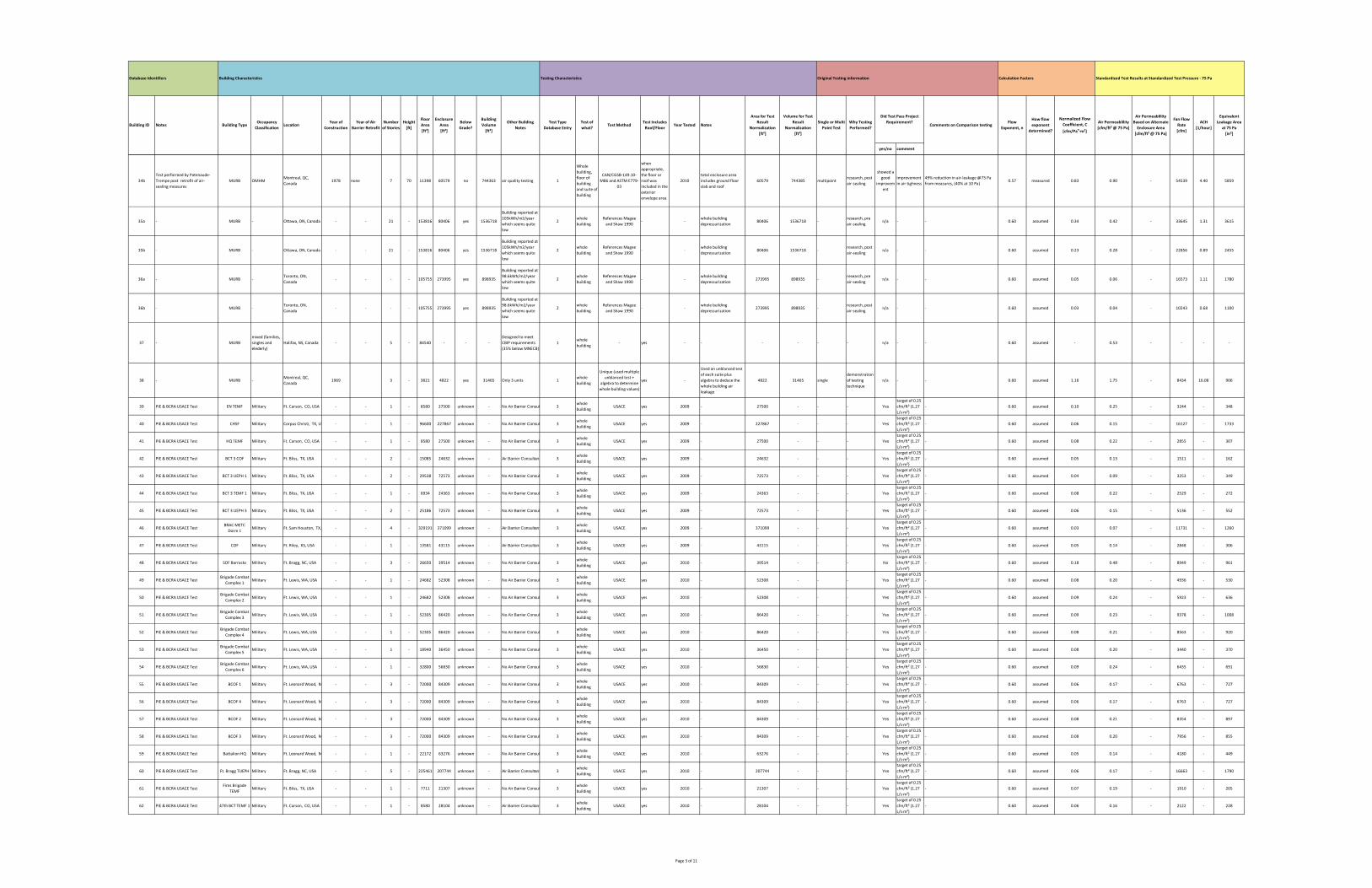
yes/no comment
How flow
exponent
determined?
Normalized Flow
Coefficient, C
[cfm/Pan∙m²]
Air Permeablility
[cfm/ft² @ 75 Pa]
Equivalent
Leakage Area
at 75 Pa
[in²]
Calculation FactorsOriginal Testing informationTesting Characteristics
Test Includes
Roof/FloorYear Tested Notes
Building CharacteristicsDatabase Identifiers
Building ID Notes Building TypeOccupancy
ClassificationLocation
Year of
Construction
Year of Air
Barrier Retrofit
Number
of Stories
Height
[ft]
Floor
Area
[ft²]
Enclosure
Area
[ft²]
Below
Grade?
Building
Volume
[ft³]
Other Building
Notes
Test Type
Database Entry
Test of
what?Test Method
Standardized Test Results at Standardized Test Pressure ‐ 75 Pa
Area for Test
Result
Normalization
[ft²]
Volume for Test
Result
Normalization
[ft³]
Comments on Comparison testingWhy Testing
Performed?
Single or Multi
Point Test
Flow
Exponent, n
Did Test Pass Project
Requirement?
Air Permeablility
Based on Alternate
Enclosure Area
[cfm/ft² @ 75 Pa]
Fan Flow
Rate
[cfm]
ACH
[1/hour]
34b
Test performed by Patenaude‐
Trempe post retrofit of air‐
sealing measures
MURB OMHMMontreal, QC,
Canada1978 none 7 70 11398 60579 no 744363 air quality testing 1
Whole
building,
floor of
building
and suite of
building
CAN/CGSB‐149.10‐
M86 and ASTM E779‐
03
when
appropriate,
the floor or
roof was
included in the
exterior
envelope area
2010
total enclosure area
includes ground floor
slab and roof
60579 744385 multipointresearch, post
air‐sealing
showed a
good
improvem
ent
improvement
in air tighness
49% reduction in air‐leakage @75 Pa
from measures, (40% at 10 Pa)0.57 measured 0.83 0.90 ‐ 54539 4.40 5859
35a ‐ MURB ‐ Ottawa, ON, Canada ‐ ‐ 21 ‐ 153816 80406 yes 1536718
Building reported at
105kWh/m2/year
which seems quite
low
2whole
building
References Magee
and Shaw 1990‐ ‐
whole building
depressurization80406 1536718 ‐
research, pre
air‐sealingn/a ‐ ‐ 0.60 assumed 0.34 0.42 ‐ 33645 1.31 3615
35b ‐ MURB ‐ Ottawa, ON, Canada ‐ ‐ 21 ‐ 153816 80406 yes 1536718
Building reported at
105kWh/m2/year
which seems quite
low
2whole
building
References Magee
and Shaw 1990‐ ‐
whole building
depressurization80406 1536718 ‐
research, post
air‐sealingn/a ‐ ‐ 0.60 assumed 0.23 0.28 ‐ 22856 0.89 2455
36a ‐ MURB ‐Toronto, ON,
Canada‐ ‐ ‐ ‐ 105755 273995 yes 898935
Building reported at
98.6kWh/m2/year
which seems quite
low
2whole
building
References Magee
and Shaw 1990‐ ‐
whole building
depressurization273995 898935 ‐
research, pre
air‐sealingn/a ‐ ‐ 0.60 assumed 0.05 0.06 ‐ 16573 1.11 1780
36b ‐ MURB ‐Toronto, ON,
Canada‐ ‐ ‐ ‐ 105755 273995 yes 898935
Building reported at
98.6kWh/m2/year
which seems quite
low
2whole
building
References Magee
and Shaw 1990‐ ‐
whole building
depressurization273995 898935 ‐
research, post
air‐sealingn/a ‐ ‐ 0.60 assumed 0.03 0.04 ‐ 10243 0.68 1100
37 ‐ MURB
mixed (families,
singles and
elederly)
Halifax, NS, Canada ‐ ‐ 5 ‐ 84540 ‐ ‐ ‐
Designed to meet
CBIP requirements
(35% below MNECB)
1whole
building‐ yes ‐ ‐ ‐ ‐ ‐ ‐ n/a ‐ ‐ 0.60 assumed ‐ 0.53 ‐ ‐ ‐ ‐
38 ‐ MURB ‐Montreal, QC,
Canada1969 3 ‐ 3821 4822 yes 31465 Only 3 units 1
whole
building
Unique (used multiple
unblanced test +
algebra to determine
whole building values)
yes ‐
Used an unblanced test
of each suite plus
algebra to deduce the
whole building air
leakage
4822 31465 single
demonstration
of testing
technique
n/a ‐ ‐ 0.60 assumed 1.16 1.75 ‐ 8434 16.08 906
39 PIE & BCRA USACE Test EN TEMF Military Ft. Carson, CO, USA ‐ ‐ 1 ‐ 8580 27500 unknown ‐ No Air Barrier Consul 3whole
buildingUSACE yes 2009 ‐ 27500 ‐ ‐ ‐ Yes
target of 0.25
cfm/ft² (1.27
L/s∙m²)
‐ 0.60 assumed 0.10 0.25 ‐ 3244 ‐ 348
40 PIE & BCRA USACE Test CHSF Military Corpus Christi, TX, US ‐ ‐ 1 ‐ 96600 227867 unknown ‐ No Air Barrier Consul 3whole
buildingUSACE yes 2009 ‐ 227867 ‐ ‐ ‐ Yes
target of 0.25
cfm/ft² (1.27
L/s∙m²)
‐ 0.60 assumed 0.06 0.15 ‐ 16127 ‐ 1733
41 PIE & BCRA USACE Test HQ TEMF Military Ft. Carson, CO, USA ‐ ‐ 1 ‐ 8580 27500 unknown ‐ No Air Barrier Consul 3whole
buildingUSACE yes 2009 ‐ 27500 ‐ ‐ ‐ Yes
target of 0.25
cfm/ft² (1.27
L/s∙m²)
‐ 0.60 assumed 0.08 0.22 ‐ 2855 ‐ 307
42 PIE & BCRA USACE Test BCT 3 COF Military Ft. Bliss, TX, USA ‐ ‐ 2 ‐ 15085 24632 unknown ‐ Air Barrier Consultant 3whole
buildingUSACE yes 2009 ‐ 24632 ‐ ‐ ‐ Yes
target of 0.25
cfm/ft² (1.27
L/s∙m²)
‐ 0.60 assumed 0.05 0.13 ‐ 1511 ‐ 162
43 PIE & BCRA USACE Test BCT 3 UEPH 1 Military Ft. Bliss, TX, USA ‐ ‐ 2 ‐ 29538 72573 unknown ‐ No Air Barrier Consul 3whole
buildingUSACE yes 2009 ‐ 72573 ‐ ‐ ‐ Yes
target of 0.25
cfm/ft² (1.27
L/s∙m²)
‐ 0.60 assumed 0.04 0.09 ‐ 3253 ‐ 349
44 PIE & BCRA USACE Test BCT 3 TEMF 1 Military Ft. Bliss, TX, USA ‐ ‐ 1 ‐ 6934 24363 unknown ‐ No Air Barrier Consul 3whole
buildingUSACE yes 2009 ‐ 24363 ‐ ‐ ‐ Yes
target of 0.25
cfm/ft² (1.27
L/s∙m²)
‐ 0.60 assumed 0.08 0.22 ‐ 2529 ‐ 272
45 PIE & BCRA USACE Test BCT 3 UEPH 3 Military Ft. Bliss, TX, USA ‐ ‐ 2 ‐ 25186 72573 unknown ‐ No Air Barrier Consul 3whole
buildingUSACE yes 2009 ‐ 72573 ‐ ‐ ‐ Yes
target of 0.25
cfm/ft² (1.27
L/s∙m²)
‐ 0.60 assumed 0.06 0.15 ‐ 5136 ‐ 552
46 PIE & BCRA USACE TestBRAC METC
Dorm 1Military Ft. Sam Houston, TX, ‐ ‐ 4 ‐ 329191 371099 unknown ‐ Air Barrier Consultant 3
whole
buildingUSACE yes 2009 ‐ 371099 ‐ ‐ ‐ Yes
target of 0.25
cfm/ft² (1.27
L/s∙m²)
‐ 0.60 assumed 0.03 0.07 ‐ 11731 ‐ 1260
47 PIE & BCRA USACE Test COF Military Ft. Riley, KS, USA ‐ ‐ 1 ‐ 13581 43115 unknown ‐ Air Barrier Consultant 3whole
buildingUSACE yes 2009 ‐ 43115 ‐ ‐ ‐ Yes
target of 0.25
cfm/ft² (1.27
L/s∙m²)
‐ 0.60 assumed 0.05 0.14 ‐ 2848 ‐ 306
48 PIE & BCRA USACE Test SOF Barracks Military Ft. Bragg, NC, USA ‐ ‐ 3 ‐ 26650 39514 unknown ‐ No Air Barrier Consul 3whole
buildingUSACE yes 2010 ‐ 39514 ‐ ‐ ‐ No
target of 0.25
cfm/ft² (1.27
L/s∙m²)
‐ 0.60 assumed 0.18 0.48 ‐ 8949 ‐ 961
49 PIE & BCRA USACE TestBrigade Combat
Complex 1Military Ft. Lewis, WA, USA ‐ ‐ 1 ‐ 24682 52308 unknown ‐ No Air Barrier Consul 3
whole
buildingUSACE yes 2010 ‐ 52308 ‐ ‐ ‐ Yes
target of 0.25
cfm/ft² (1.27
L/s∙m²)
‐ 0.60 assumed 0.08 0.20 ‐ 4936 ‐ 530
50 PIE & BCRA USACE TestBrigade Combat
Complex 2Military Ft. Lewis, WA, USA ‐ ‐ 1 ‐ 24682 52308 unknown ‐ No Air Barrier Consul 3
whole
buildingUSACE yes 2010 ‐ 52308 ‐ ‐ ‐ Yes
target of 0.25
cfm/ft² (1.27
L/s∙m²)
‐ 0.60 assumed 0.09 0.24 ‐ 5923 ‐ 636
51 PIE & BCRA USACE TestBrigade Combat
Complex 3Military Ft. Lewis, WA, USA ‐ ‐ 1 ‐ 52305 86420 unknown ‐ No Air Barrier Consul 3
whole
buildingUSACE yes 2010 ‐ 86420 ‐ ‐ ‐ Yes
target of 0.25
cfm/ft² (1.27
L/s∙m²)
‐ 0.60 assumed 0.09 0.23 ‐ 9378 ‐ 1008
52 PIE & BCRA USACE TestBrigade Combat
Complex 4Military Ft. Lewis, WA, USA ‐ ‐ 1 ‐ 52305 86420 unknown ‐ No Air Barrier Consul 3
whole
buildingUSACE yes 2010 ‐ 86420 ‐ ‐ ‐ Yes
target of 0.25
cfm/ft² (1.27
L/s∙m²)
‐ 0.60 assumed 0.08 0.21 ‐ 8563 ‐ 920
53 PIE & BCRA USACE TestBrigade Combat
Complex 5Military Ft. Lewis, WA, USA ‐ ‐ 1 ‐ 18940 36450 unknown ‐ No Air Barrier Consul 3
whole
buildingUSACE yes 2010 ‐ 36450 ‐ ‐ ‐ Yes
target of 0.25
cfm/ft² (1.27
L/s∙m²)
‐ 0.60 assumed 0.08 0.20 ‐ 3440 ‐ 370
54 PIE & BCRA USACE TestBrigade Combat
Complex 6Military Ft. Lewis, WA, USA ‐ ‐ 1 ‐ 32800 56830 unknown ‐ No Air Barrier Consul 3
whole
buildingUSACE yes 2010 ‐ 56830 ‐ ‐ ‐ Yes
target of 0.25
cfm/ft² (1.27
L/s∙m²)
‐ 0.60 assumed 0.09 0.24 ‐ 6435 ‐ 691
55 PIE & BCRA USACE Test BCOF 1 Military Ft. Leonard Wood, M ‐ ‐ 3 ‐ 72000 84309 unknown ‐ No Air Barrier Consul 3whole
buildingUSACE yes 2010 ‐ 84309 ‐ ‐ ‐ Yes
target of 0.25
cfm/ft² (1.27
L/s∙m²)
‐ 0.60 assumed 0.06 0.17 ‐ 6763 ‐ 727
56 PIE & BCRA USACE Test BCOF 4 Military Ft. Leonard Wood, M ‐ ‐ 3 ‐ 72000 84309 unknown ‐ No Air Barrier Consul 3whole
buildingUSACE yes 2010 ‐ 84309 ‐ ‐ ‐ Yes
target of 0.25
cfm/ft² (1.27
L/s∙m²)
‐ 0.60 assumed 0.06 0.17 ‐ 6763 ‐ 727
57 PIE & BCRA USACE Test BCOF 2 Military Ft. Leonard Wood, M ‐ ‐ 3 ‐ 72000 84309 unknown ‐ No Air Barrier Consul 3whole
buildingUSACE yes 2010 ‐ 84309 ‐ ‐ ‐ Yes
target of 0.25
cfm/ft² (1.27
L/s∙m²)
‐ 0.60 assumed 0.08 0.21 ‐ 8354 ‐ 897
58 PIE & BCRA USACE Test BCOF 3 Military Ft. Leonard Wood, M ‐ ‐ 3 ‐ 72000 84309 unknown ‐ No Air Barrier Consul 3whole
buildingUSACE yes 2010 ‐ 84309 ‐ ‐ ‐ Yes
target of 0.25
cfm/ft² (1.27
L/s∙m²)
‐ 0.60 assumed 0.08 0.20 ‐ 7956 ‐ 855
59 PIE & BCRA USACE Test Battalion HQ Military Ft. Leonard Wood, M ‐ ‐ 1 ‐ 22172 63276 unknown ‐ No Air Barrier Consul 3whole
buildingUSACE yes 2010 ‐ 63276 ‐ ‐ ‐ Yes
target of 0.25
cfm/ft² (1.27
L/s∙m²)
‐ 0.60 assumed 0.05 0.14 ‐ 4180 ‐ 449
60 PIE & BCRA USACE Test Ft. Bragg TUEPH Military Ft. Bragg, NC, USA ‐ ‐ 5 ‐ 225461 207744 unknown ‐ Air Barrier Consultant 3whole
buildingUSACE yes 2010 ‐ 207744 ‐ ‐ ‐ Yes
target of 0.25
cfm/ft² (1.27
L/s∙m²)
‐ 0.60 assumed 0.06 0.17 ‐ 16663 ‐ 1790
61 PIE & BCRA USACE TestFires Brigade
TEMFMilitary Ft. Bliss, TX, USA ‐ ‐ 1 ‐ 7711 21307 unknown ‐ No Air Barrier Consul 3
whole
buildingUSACE yes 2010 ‐ 21307 ‐ ‐ ‐ Yes
target of 0.25
cfm/ft² (1.27
L/s∙m²)
‐ 0.60 assumed 0.07 0.19 ‐ 1910 ‐ 205
62 PIE & BCRA USACE Test 47th BCT TEMF 1 Military Ft. Carson, CO, USA ‐ ‐ 1 ‐ 8580 28104 unknown ‐ Air Barrier Consultant 3whole
buildingUSACE yes 2010 ‐ 28104 ‐ ‐ ‐ Yes
target of 0.25
cfm/ft² (1.27
L/s∙m²)
‐ 0.60 assumed 0.06 0.16 ‐ 2122 ‐ 228
Page 3 of 11
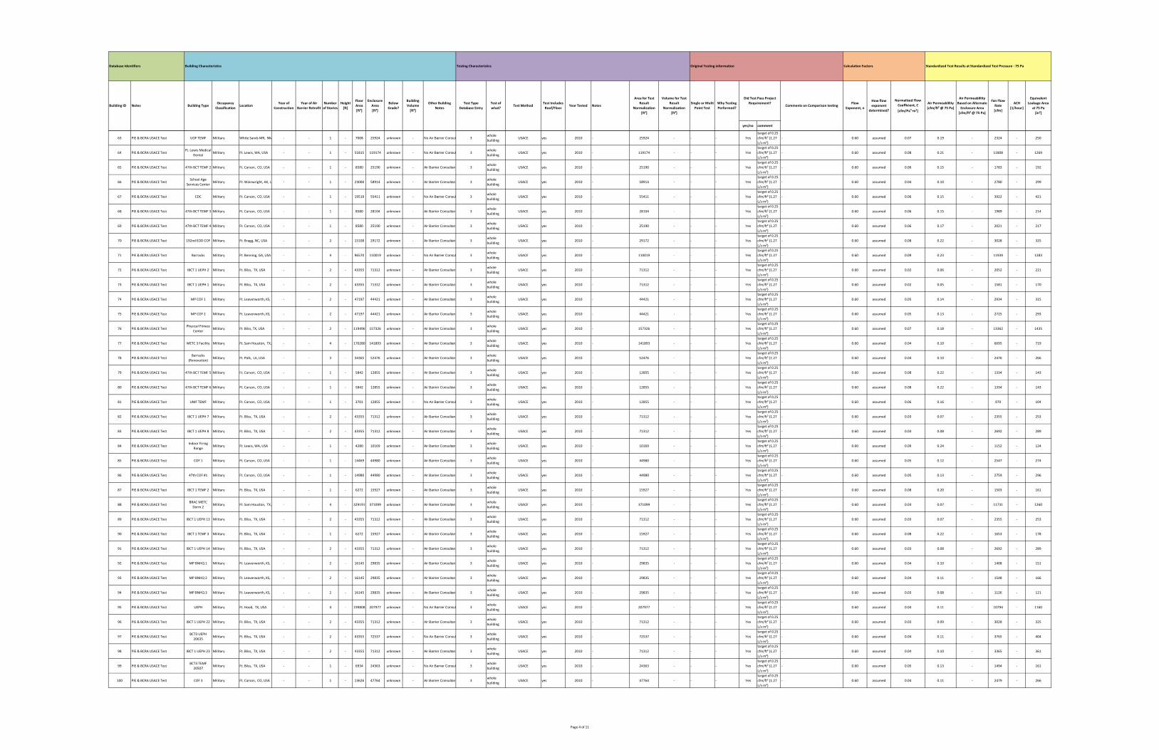
yes/no comment
How flow
exponent
determined?
Normalized Flow
Coefficient, C
[cfm/Pan∙m²]
Air Permeablility
[cfm/ft² @ 75 Pa]
Equivalent
Leakage Area
at 75 Pa
[in²]
Calculation FactorsOriginal Testing informationTesting Characteristics
Test Includes
Roof/FloorYear Tested Notes
Building CharacteristicsDatabase Identifiers
Building ID Notes Building TypeOccupancy
ClassificationLocation
Year of
Construction
Year of Air
Barrier Retrofit
Number
of Stories
Height
[ft]
Floor
Area
[ft²]
Enclosure
Area
[ft²]
Below
Grade?
Building
Volume
[ft³]
Other Building
Notes
Test Type
Database Entry
Test of
what?Test Method
Standardized Test Results at Standardized Test Pressure ‐ 75 Pa
Area for Test
Result
Normalization
[ft²]
Volume for Test
Result
Normalization
[ft³]
Comments on Comparison testingWhy Testing
Performed?
Single or Multi
Point Test
Flow
Exponent, n
Did Test Pass Project
Requirement?
Air Permeablility
Based on Alternate
Enclosure Area
[cfm/ft² @ 75 Pa]
Fan Flow
Rate
[cfm]
ACH
[1/hour]
63 PIE & BCRA USACE Test UOF TEMF Military White Sands MR, NM ‐ ‐ 1 ‐ 7008 25924 unknown ‐ No Air Barrier Consul 3whole
buildingUSACE yes 2010 ‐ 25924 ‐ ‐ ‐ Yes
target of 0.25
cfm/ft² (1.27
L/s∙m²)
‐ 0.60 assumed 0.07 0.19 ‐ 2324 ‐ 250
64 PIE & BCRA USACE TestFt. Lewis Medical
DentalMilitary Ft. Lewis, WA, USA ‐ ‐ 1 ‐ 51815 119174 unknown ‐ No Air Barrier Consul 3
whole
buildingUSACE yes 2010 ‐ 119174 ‐ ‐ ‐ Yes
target of 0.25
cfm/ft² (1.27
L/s∙m²)
‐ 0.60 assumed 0.08 0.21 ‐ 11808 ‐ 1269
65 PIE & BCRA USACE Test 47th BCT TEMF 2 Military Ft. Carson, CO, USA ‐ ‐ 1 ‐ 8580 25190 unknown ‐ Air Barrier Consultant 3whole
buildingUSACE yes 2010 ‐ 25190 ‐ ‐ ‐ Yes
target of 0.25
cfm/ft² (1.27
L/s∙m²)
‐ 0.60 assumed 0.06 0.15 ‐ 1783 ‐ 192
66 PIE & BCRA USACE TestSchool Age
Services CenterMilitary Ft. Wainwright, AK, U ‐ ‐ 1 ‐ 23000 58914 unknown ‐ Air Barrier Consultant 3
whole
buildingUSACE yes 2010 ‐ 58914 ‐ ‐ ‐ Yes
target of 0.25
cfm/ft² (1.27
L/s∙m²)
‐ 0.60 assumed 0.04 0.10 ‐ 2780 ‐ 299
67 PIE & BCRA USACE Test CDC Military Ft. Carson, CO, USA ‐ ‐ 1 ‐ 19519 55411 unknown ‐ No Air Barrier Consul 3whole
buildingUSACE yes 2010 ‐ 55411 ‐ ‐ ‐ Yes
target of 0.25
cfm/ft² (1.27
L/s∙m²)
‐ 0.60 assumed 0.06 0.15 ‐ 3922 ‐ 421
68 PIE & BCRA USACE Test 47th BCT TEMF 3 Military Ft. Carson, CO, USA ‐ ‐ 1 ‐ 8580 28104 unknown ‐ Air Barrier Consultant 3whole
buildingUSACE yes 2010 ‐ 28104 ‐ ‐ ‐ Yes
target of 0.25
cfm/ft² (1.27
L/s∙m²)
‐ 0.60 assumed 0.06 0.15 ‐ 1989 ‐ 214
69 PIE & BCRA USACE Test 47th BCT TEMF 4 Military Ft. Carson, CO, USA ‐ ‐ 1 ‐ 8580 25190 unknown ‐ Air Barrier Consultant 3whole
buildingUSACE yes 2010 ‐ 25190 ‐ ‐ ‐ Yes
target of 0.25
cfm/ft² (1.27
L/s∙m²)
‐ 0.60 assumed 0.06 0.17 ‐ 2021 ‐ 217
70 PIE & BCRA USACE Test 192nd EOD COF Military Ft. Bragg, NC, USA ‐ ‐ 2 ‐ 15108 29172 unknown ‐ Air Barrier Consultant 3whole
buildingUSACE yes 2010 ‐ 29172 ‐ ‐ ‐ Yes
target of 0.25
cfm/ft² (1.27
L/s∙m²)
‐ 0.60 assumed 0.08 0.22 ‐ 3028 ‐ 325
71 PIE & BCRA USACE Test Barracks Military Ft. Benning, GA, USA ‐ ‐ 4 ‐ 96570 110019 unknown ‐ No Air Barrier Consul 3whole
buildingUSACE yes 2010 ‐ 110019 ‐ ‐ ‐ Yes
target of 0.25
cfm/ft² (1.27
L/s∙m²)
‐ 0.60 assumed 0.09 0.23 ‐ 11939 ‐ 1283
72 PIE & BCRA USACE Test IBCT 1 UEPH 2 Military Ft. Bliss, TX, USA ‐ ‐ 2 ‐ 43355 71312 unknown ‐ Air Barrier Consultant 3whole
buildingUSACE yes 2010 ‐ 71312 ‐ ‐ ‐ Yes
target of 0.25
cfm/ft² (1.27
L/s∙m²)
‐ 0.60 assumed 0.02 0.06 ‐ 2052 ‐ 221
73 PIE & BCRA USACE Test IBCT 1 UEPH 1 Military Ft. Bliss, TX, USA ‐ ‐ 2 ‐ 43355 71312 unknown ‐ Air Barrier Consultant 3whole
buildingUSACE yes 2010 ‐ 71312 ‐ ‐ ‐ Yes
target of 0.25
cfm/ft² (1.27
L/s∙m²)
‐ 0.60 assumed 0.02 0.05 ‐ 1581 ‐ 170
74 PIE & BCRA USACE Test MP COF 1 Military Ft. Leavenworth, KS, U ‐ ‐ 2 ‐ 47197 44421 unknown ‐ Air Barrier Consultant 3whole
buildingUSACE yes 2010 ‐ 44421 ‐ ‐ ‐ Yes
target of 0.25
cfm/ft² (1.27
L/s∙m²)
‐ 0.60 assumed 0.05 0.14 ‐ 2934 ‐ 315
75 PIE & BCRA USACE Test MP COF 2 Military Ft. Leavenworth, KS, U ‐ ‐ 2 ‐ 47197 44421 unknown ‐ Air Barrier Consultant 3whole
buildingUSACE yes 2010 ‐ 44421 ‐ ‐ ‐ Yes
target of 0.25
cfm/ft² (1.27
L/s∙m²)
‐ 0.60 assumed 0.05 0.13 ‐ 2725 ‐ 293
76 PIE & BCRA USACE TestPhysical Fitness
CenterMilitary Ft. Bliss, TX, USA ‐ ‐ 2 ‐ 119496 157326 unknown ‐ Air Barrier Consultant 3
whole
buildingUSACE yes 2010 ‐ 157326 ‐ ‐ ‐ Yes
target of 0.25
cfm/ft² (1.27
L/s∙m²)
‐ 0.60 assumed 0.07 0.18 ‐ 13362 ‐ 1435
77 PIE & BCRA USACE Test METC 3 Facility Military Ft. Sam Houston, TX, ‐ ‐ 4 ‐ 170280 141893 unknown ‐ Air Barrier Consultant 3whole
buildingUSACE yes 2010 ‐ 141893 ‐ ‐ ‐ Yes
target of 0.25
cfm/ft² (1.27
L/s∙m²)
‐ 0.60 assumed 0.04 0.10 ‐ 6695 ‐ 719
78 PIE & BCRA USACE TestBarracks
(Renovation)Military Ft. Polk, LA, USA ‐ ‐ 3 ‐ 34365 52476 unknown ‐ Air Barrier Consultant 3
whole
buildingUSACE yes 2010 ‐ 52476 ‐ ‐ ‐ Yes
target of 0.25
cfm/ft² (1.27
L/s∙m²)
‐ 0.60 assumed 0.04 0.10 ‐ 2476 ‐ 266
79 PIE & BCRA USACE Test 47th BCT TEMF 5 Military Ft. Carson, CO, USA ‐ ‐ 1 ‐ 5842 12855 unknown ‐ Air Barrier Consultant 3whole
buildingUSACE yes 2010 ‐ 12855 ‐ ‐ ‐ Yes
target of 0.25
cfm/ft² (1.27
L/s∙m²)
‐ 0.60 assumed 0.08 0.22 ‐ 1334 ‐ 143
80 PIE & BCRA USACE Test 47th BCT TEMF 6 Military Ft. Carson, CO, USA ‐ ‐ 1 ‐ 5842 12855 unknown ‐ Air Barrier Consultant 3whole
buildingUSACE yes 2010 ‐ 12855 ‐ ‐ ‐ Yes
target of 0.25
cfm/ft² (1.27
L/s∙m²)
‐ 0.60 assumed 0.08 0.22 ‐ 1334 ‐ 143
81 PIE & BCRA USACE Test UMF TEMF Military Ft. Carson, CO, USA ‐ ‐ 1 ‐ 3701 12855 unknown ‐ No Air Barrier Consul 3whole
buildingUSACE yes 2010 ‐ 12855 ‐ ‐ ‐ Yes
target of 0.25
cfm/ft² (1.27
L/s∙m²)
‐ 0.60 assumed 0.06 0.16 ‐ 970 ‐ 104
82 PIE & BCRA USACE Test IBCT 1 UEPH 7 Military Ft. Bliss, TX, USA ‐ ‐ 2 ‐ 43355 71312 unknown ‐ Air Barrier Consultant 3whole
buildingUSACE yes 2010 ‐ 71312 ‐ ‐ ‐ Yes
target of 0.25
cfm/ft² (1.27
L/s∙m²)
‐ 0.60 assumed 0.03 0.07 ‐ 2355 ‐ 253
83 PIE & BCRA USACE Test IBCT 1 UEPH 8 Military Ft. Bliss, TX, USA ‐ ‐ 2 ‐ 43355 71312 unknown ‐ Air Barrier Consultant 3whole
buildingUSACE yes 2010 ‐ 71312 ‐ ‐ ‐ Yes
target of 0.25
cfm/ft² (1.27
L/s∙m²)
‐ 0.60 assumed 0.03 0.08 ‐ 2692 ‐ 289
84 PIE & BCRA USACE TestIndoor Firing
RangeMilitary Ft. Lewis, WA, USA ‐ ‐ 1 ‐ 4280 10169 unknown ‐ Air Barrier Consultant 3
whole
buildingUSACE yes 2010 ‐ 10169 ‐ ‐ ‐ Yes
target of 0.25
cfm/ft² (1.27
L/s∙m²)
‐ 0.60 assumed 0.09 0.24 ‐ 1152 ‐ 124
85 PIE & BCRA USACE Test COF 1 Military Ft. Carson, CO, USA ‐ ‐ 1 ‐ 14469 44980 unknown ‐ Air Barrier Consultant 3whole
buildingUSACE yes 2010 ‐ 44980 ‐ ‐ ‐ Yes
target of 0.25
cfm/ft² (1.27
L/s∙m²)
‐ 0.60 assumed 0.05 0.12 ‐ 2547 ‐ 274
86 PIE & BCRA USACE Test 47th COF #1 Military Ft. Carson, CO, USA ‐ ‐ 1 ‐ 14980 44980 unknown ‐ Air Barrier Consultant 3whole
buildingUSACE yes 2010 ‐ 44980 ‐ ‐ ‐ Yes
target of 0.25
cfm/ft² (1.27
L/s∙m²)
‐ 0.60 assumed 0.05 0.13 ‐ 2759 ‐ 296
87 PIE & BCRA USACE Test IBCT 1 TEMF 2 Military Ft. Bliss, TX, USA ‐ ‐ 1 ‐ 6272 15927 unknown ‐ Air Barrier Consultant 3whole
buildingUSACE yes 2010 ‐ 15927 ‐ ‐ ‐ Yes
target of 0.25
cfm/ft² (1.27
L/s∙m²)
‐ 0.60 assumed 0.08 0.20 ‐ 1503 ‐ 161
88 PIE & BCRA USACE TestBRAC METC
Dorm 2Military Ft. Sam Houston, TX, ‐ ‐ 4 ‐ 329191 371099 unknown ‐ Air Barrier Consultant 3
whole
buildingUSACE yes 2010 ‐ 371099 ‐ ‐ ‐ Yes
target of 0.25
cfm/ft² (1.27
L/s∙m²)
‐ 0.60 assumed 0.03 0.07 ‐ 11731 ‐ 1260
89 PIE & BCRA USACE Test IBCT 1 UEPH 13 Military Ft. Bliss, TX, USA ‐ ‐ 2 ‐ 43355 71312 unknown ‐ Air Barrier Consultant 3whole
buildingUSACE yes 2010 ‐ 71312 ‐ ‐ ‐ Yes
target of 0.25
cfm/ft² (1.27
L/s∙m²)
‐ 0.60 assumed 0.03 0.07 ‐ 2355 ‐ 253
90 PIE & BCRA USACE Test IBCT 1 TEMF 3 Military Ft. Bliss, TX, USA ‐ ‐ 1 ‐ 6272 15927 unknown ‐ Air Barrier Consultant 3whole
buildingUSACE yes 2010 ‐ 15927 ‐ ‐ ‐ Yes
target of 0.25
cfm/ft² (1.27
L/s∙m²)
‐ 0.60 assumed 0.08 0.22 ‐ 1653 ‐ 178
91 PIE & BCRA USACE Test IBCT 1 UEPH 14 Military Ft. Bliss, TX, USA ‐ ‐ 2 ‐ 43355 71312 unknown ‐ Air Barrier Consultant 3whole
buildingUSACE yes 2010 ‐ 71312 ‐ ‐ ‐ Yes
target of 0.25
cfm/ft² (1.27
L/s∙m²)
‐ 0.60 assumed 0.03 0.08 ‐ 2692 ‐ 289
92 PIE & BCRA USACE Test MP BNHQ 1 Military Ft. Leavenworth, KS, U ‐ ‐ 2 ‐ 16145 29835 unknown ‐ Air Barrier Consultant 3whole
buildingUSACE yes 2010 ‐ 29835 ‐ ‐ ‐ Yes
target of 0.25
cfm/ft² (1.27
L/s∙m²)
‐ 0.60 assumed 0.04 0.10 ‐ 1408 ‐ 151
93 PIE & BCRA USACE Test MP BNHQ 2 Military Ft. Leavenworth, KS, U ‐ ‐ 2 ‐ 16145 29835 unknown ‐ Air Barrier Consultant 3whole
buildingUSACE yes 2010 ‐ 29835 ‐ ‐ ‐ Yes
target of 0.25
cfm/ft² (1.27
L/s∙m²)
‐ 0.60 assumed 0.04 0.11 ‐ 1548 ‐ 166
94 PIE & BCRA USACE Test MP BNHQ 3 Military Ft. Leavenworth, KS, U ‐ ‐ 2 ‐ 16145 29835 unknown ‐ Air Barrier Consultant 3whole
buildingUSACE yes 2010 ‐ 29835 ‐ ‐ ‐ Yes
target of 0.25
cfm/ft² (1.27
L/s∙m²)
‐ 0.60 assumed 0.03 0.08 ‐ 1126 ‐ 121
95 PIE & BCRA USACE Test UEPH Military Ft. Hood, TX, USA ‐ ‐ 4 ‐ 199808 207977 unknown ‐ No Air Barrier Consul 3whole
buildingUSACE yes 2010 ‐ 207977 ‐ ‐ ‐ Yes
target of 0.25
cfm/ft² (1.27
L/s∙m²)
‐ 0.60 assumed 0.04 0.11 ‐ 10794 ‐ 1160
96 PIE & BCRA USACE Test IBCT 1 UEPH 22 Military Ft. Bliss, TX, USA ‐ ‐ 2 ‐ 43355 71312 unknown ‐ Air Barrier Consultant 3whole
buildingUSACE yes 2010 ‐ 71312 ‐ ‐ ‐ Yes
target of 0.25
cfm/ft² (1.27
L/s∙m²)
‐ 0.60 assumed 0.03 0.09 ‐ 3028 ‐ 325
97 PIE & BCRA USACE TestBCT3 UEPH
20635Military Ft. Bliss, TX, USA ‐ ‐ 2 ‐ 43355 72537 unknown ‐ No Air Barrier Consul 3
whole
buildingUSACE yes 2010 ‐ 72537 ‐ ‐ ‐ Yes
target of 0.25
cfm/ft² (1.27
L/s∙m²)
‐ 0.60 assumed 0.04 0.11 ‐ 3765 ‐ 404
98 PIE & BCRA USACE Test IBCT 1 UEPH 23 Military Ft. Bliss, TX, USA ‐ ‐ 2 ‐ 43355 71312 unknown ‐ Air Barrier Consultant 3whole
buildingUSACE yes 2010 ‐ 71312 ‐ ‐ ‐ Yes
target of 0.25
cfm/ft² (1.27
L/s∙m²)
‐ 0.60 assumed 0.04 0.10 ‐ 3365 ‐ 361
99 PIE & BCRA USACE TestBCT3 TEMF
20507Military Ft. Bliss, TX, USA ‐ ‐ 1 ‐ 6934 24363 unknown ‐ No Air Barrier Consul 3
whole
buildingUSACE yes 2010 ‐ 24363 ‐ ‐ ‐ Yes
target of 0.25
cfm/ft² (1.27
L/s∙m²)
‐ 0.60 assumed 0.05 0.13 ‐ 1494 ‐ 161
100 PIE & BCRA USACE Test COF 3 Military Ft. Carson, CO, USA ‐ ‐ 1 ‐ 13626 47764 unknown ‐ Air Barrier Consultant 3whole
buildingUSACE yes 2010 ‐ 47764 ‐ ‐ ‐ Yes
target of 0.25
cfm/ft² (1.27
L/s∙m²)
‐ 0.60 assumed 0.04 0.11 ‐ 2479 ‐ 266
Page 4 of 11
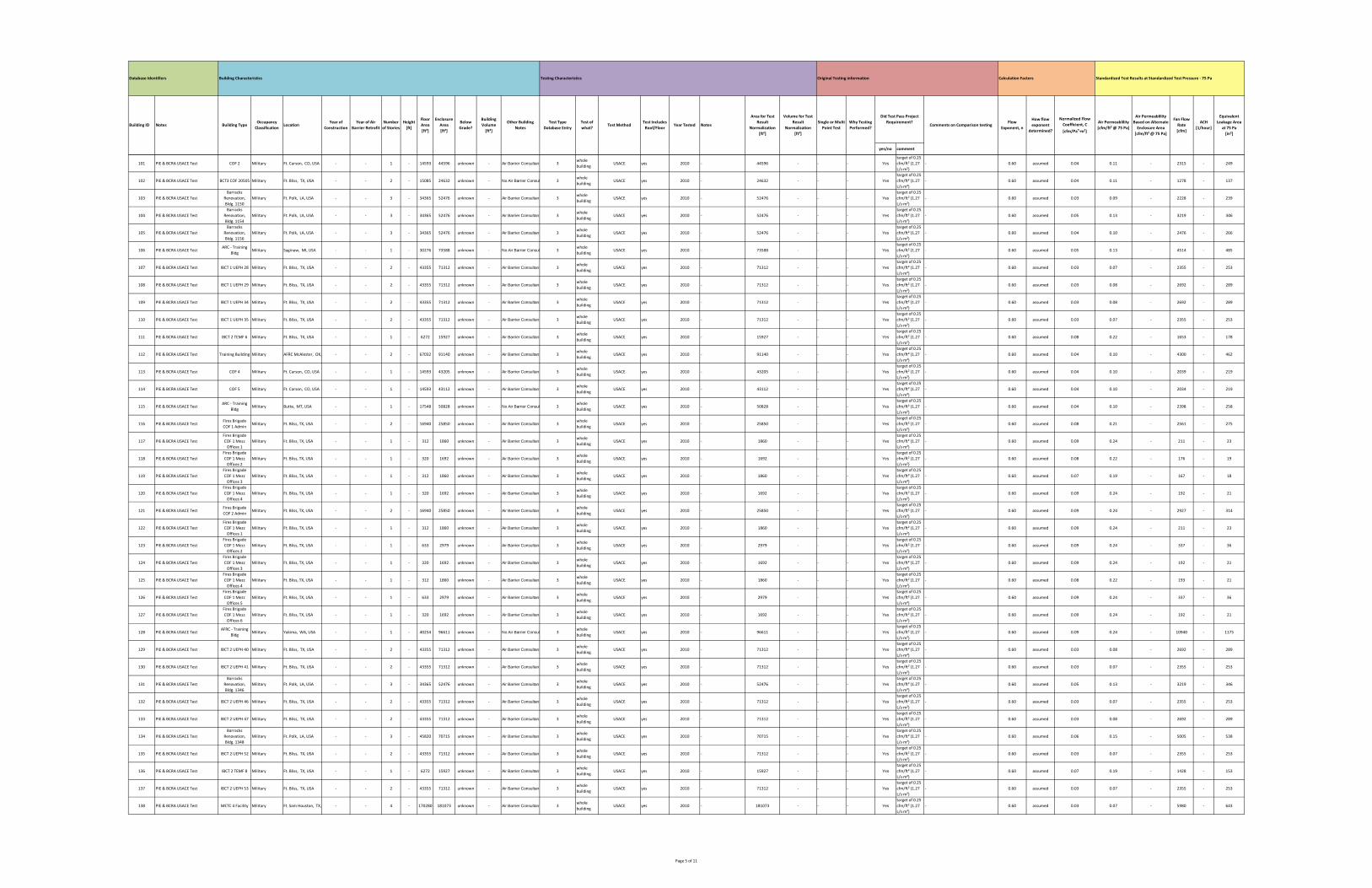
yes/no comment
How flow
exponent
determined?
Normalized Flow
Coefficient, C
[cfm/Pan∙m²]
Air Permeablility
[cfm/ft² @ 75 Pa]
Equivalent
Leakage Area
at 75 Pa
[in²]
Calculation FactorsOriginal Testing informationTesting Characteristics
Test Includes
Roof/FloorYear Tested Notes
Building CharacteristicsDatabase Identifiers
Building ID Notes Building TypeOccupancy
ClassificationLocation
Year of
Construction
Year of Air
Barrier Retrofit
Number
of Stories
Height
[ft]
Floor
Area
[ft²]
Enclosure
Area
[ft²]
Below
Grade?
Building
Volume
[ft³]
Other Building
Notes
Test Type
Database Entry
Test of
what?Test Method
Standardized Test Results at Standardized Test Pressure ‐ 75 Pa
Area for Test
Result
Normalization
[ft²]
Volume for Test
Result
Normalization
[ft³]
Comments on Comparison testingWhy Testing
Performed?
Single or Multi
Point Test
Flow
Exponent, n
Did Test Pass Project
Requirement?
Air Permeablility
Based on Alternate
Enclosure Area
[cfm/ft² @ 75 Pa]
Fan Flow
Rate
[cfm]
ACH
[1/hour]
101 PIE & BCRA USACE Test COF 2 Military Ft. Carson, CO, USA ‐ ‐ 1 ‐ 14593 44596 unknown ‐ Air Barrier Consultant 3whole
buildingUSACE yes 2010 ‐ 44596 ‐ ‐ ‐ Yes
target of 0.25
cfm/ft² (1.27
L/s∙m²)
‐ 0.60 assumed 0.04 0.11 ‐ 2315 ‐ 249
102 PIE & BCRA USACE Test BCT3 COF 20505 Military Ft. Bliss, TX, USA ‐ ‐ 2 ‐ 15085 24632 unknown ‐ No Air Barrier Consul 3whole
buildingUSACE yes 2010 ‐ 24632 ‐ ‐ ‐ Yes
target of 0.25
cfm/ft² (1.27
L/s∙m²)
‐ 0.60 assumed 0.04 0.11 ‐ 1278 ‐ 137
103 PIE & BCRA USACE Test
Barracks
Renovation,
Bldg. 1150
Military Ft. Polk, LA, USA ‐ ‐ 3 ‐ 34365 52476 unknown ‐ Air Barrier Consultant 3whole
buildingUSACE yes 2010 ‐ 52476 ‐ ‐ ‐ Yes
target of 0.25
cfm/ft² (1.27
L/s∙m²)
‐ 0.60 assumed 0.03 0.09 ‐ 2228 ‐ 239
104 PIE & BCRA USACE Test
Barracks
Renovation,
Bldg. 1154
Military Ft. Polk, LA, USA ‐ ‐ 3 ‐ 34365 52476 unknown ‐ Air Barrier Consultant 3whole
buildingUSACE yes 2010 ‐ 52476 ‐ ‐ ‐ Yes
target of 0.25
cfm/ft² (1.27
L/s∙m²)
‐ 0.60 assumed 0.05 0.13 ‐ 3219 ‐ 346
105 PIE & BCRA USACE Test
Barracks
Renovation,
Bldg. 1156
Military Ft. Polk, LA, USA ‐ ‐ 3 ‐ 34365 52476 unknown ‐ Air Barrier Consultant 3whole
buildingUSACE yes 2010 ‐ 52476 ‐ ‐ ‐ Yes
target of 0.25
cfm/ft² (1.27
L/s∙m²)
‐ 0.60 assumed 0.04 0.10 ‐ 2476 ‐ 266
106 PIE & BCRA USACE TestARC ‐ Training
BldgMilitary Saginaw, MI, USA ‐ ‐ 1 ‐ 30276 73588 unknown ‐ No Air Barrier Consul 3
whole
buildingUSACE yes 2010 ‐ 73588 ‐ ‐ ‐ Yes
target of 0.25
cfm/ft² (1.27
L/s∙m²)
‐ 0.60 assumed 0.05 0.13 ‐ 4514 ‐ 485
107 PIE & BCRA USACE Test IBCT 1 UEPH 28 Military Ft. Bliss, TX, USA ‐ ‐ 2 ‐ 43355 71312 unknown ‐ Air Barrier Consultant 3whole
buildingUSACE yes 2010 ‐ 71312 ‐ ‐ ‐ Yes
target of 0.25
cfm/ft² (1.27
L/s∙m²)
‐ 0.60 assumed 0.03 0.07 ‐ 2355 ‐ 253
108 PIE & BCRA USACE Test IBCT 1 UEPH 29 Military Ft. Bliss, TX, USA ‐ ‐ 2 ‐ 43355 71312 unknown ‐ Air Barrier Consultant 3whole
buildingUSACE yes 2010 ‐ 71312 ‐ ‐ ‐ Yes
target of 0.25
cfm/ft² (1.27
L/s∙m²)
‐ 0.60 assumed 0.03 0.08 ‐ 2692 ‐ 289
109 PIE & BCRA USACE Test IBCT 1 UEPH 34 Military Ft. Bliss, TX, USA ‐ ‐ 2 ‐ 43355 71312 unknown ‐ Air Barrier Consultant 3whole
buildingUSACE yes 2010 ‐ 71312 ‐ ‐ ‐ Yes
target of 0.25
cfm/ft² (1.27
L/s∙m²)
‐ 0.60 assumed 0.03 0.08 ‐ 2692 ‐ 289
110 PIE & BCRA USACE Test IBCT 1 UEPH 35 Military Ft. Bliss, TX, USA ‐ ‐ 2 ‐ 43355 71312 unknown ‐ Air Barrier Consultant 3whole
buildingUSACE yes 2010 ‐ 71312 ‐ ‐ ‐ Yes
target of 0.25
cfm/ft² (1.27
L/s∙m²)
‐ 0.60 assumed 0.03 0.07 ‐ 2355 ‐ 253
111 PIE & BCRA USACE Test IBCT 2 TEMF 6 Military Ft. Bliss, TX, USA ‐ ‐ 1 ‐ 6272 15927 unknown ‐ Air Barrier Consultant 3whole
buildingUSACE yes 2010 ‐ 15927 ‐ ‐ ‐ Yes
target of 0.25
cfm/ft² (1.27
L/s∙m²)
‐ 0.60 assumed 0.08 0.22 ‐ 1653 ‐ 178
112 PIE & BCRA USACE Test Training Building Military AFRC McAlester, OK, ‐ ‐ 2 ‐ 67032 91140 unknown ‐ Air Barrier Consultant 3whole
buildingUSACE yes 2010 ‐ 91140 ‐ ‐ ‐ Yes
target of 0.25
cfm/ft² (1.27
L/s∙m²)
‐ 0.60 assumed 0.04 0.10 ‐ 4300 ‐ 462
113 PIE & BCRA USACE Test COF 4 Military Ft. Carson, CO, USA ‐ ‐ 1 ‐ 14593 43205 unknown ‐ Air Barrier Consultant 3whole
buildingUSACE yes 2010 ‐ 43205 ‐ ‐ ‐ Yes
target of 0.25
cfm/ft² (1.27
L/s∙m²)
‐ 0.60 assumed 0.04 0.10 ‐ 2039 ‐ 219
114 PIE & BCRA USACE Test COF 5 Military Ft. Carson, CO, USA ‐ ‐ 1 ‐ 14593 43112 unknown ‐ Air Barrier Consultant 3whole
buildingUSACE yes 2010 ‐ 43112 ‐ ‐ ‐ Yes
target of 0.25
cfm/ft² (1.27
L/s∙m²)
‐ 0.60 assumed 0.04 0.10 ‐ 2034 ‐ 219
115 PIE & BCRA USACE TestARC ‐ Training
BldgMilitary Butte, MT, USA ‐ ‐ 1 ‐ 17548 50828 unknown ‐ No Air Barrier Consul 3
whole
buildingUSACE yes 2010 ‐ 50828 ‐ ‐ ‐ Yes
target of 0.25
cfm/ft² (1.27
L/s∙m²)
‐ 0.60 assumed 0.04 0.10 ‐ 2398 ‐ 258
116 PIE & BCRA USACE TestFires Brigade
COF 1 AdminMilitary Ft. Bliss, TX, USA ‐ ‐ 2 ‐ 16940 25850 unknown ‐ Air Barrier Consultant 3
whole
buildingUSACE yes 2010 ‐ 25850 ‐ ‐ ‐ Yes
target of 0.25
cfm/ft² (1.27
L/s∙m²)
‐ 0.60 assumed 0.08 0.21 ‐ 2561 ‐ 275
117 PIE & BCRA USACE Test
Fires Brigade
COF 1 Mezz
Offices 1
Military Ft. Bliss, TX, USA ‐ ‐ 1 ‐ 312 1860 unknown ‐ Air Barrier Consultant 3whole
buildingUSACE yes 2010 ‐ 1860 ‐ ‐ ‐ Yes
target of 0.25
cfm/ft² (1.27
L/s∙m²)
‐ 0.60 assumed 0.09 0.24 ‐ 211 ‐ 23
118 PIE & BCRA USACE Test
Fires Brigade
COF 1 Mezz
Offices 2
Military Ft. Bliss, TX, USA ‐ ‐ 1 ‐ 320 1692 unknown ‐ Air Barrier Consultant 3whole
buildingUSACE yes 2010 ‐ 1692 ‐ ‐ ‐ Yes
target of 0.25
cfm/ft² (1.27
L/s∙m²)
‐ 0.60 assumed 0.08 0.22 ‐ 176 ‐ 19
119 PIE & BCRA USACE Test
Fires Brigade
COF 1 Mezz
Offices 3
Military Ft. Bliss, TX, USA ‐ ‐ 1 ‐ 312 1860 unknown ‐ Air Barrier Consultant 3whole
buildingUSACE yes 2010 ‐ 1860 ‐ ‐ ‐ Yes
target of 0.25
cfm/ft² (1.27
L/s∙m²)
‐ 0.60 assumed 0.07 0.19 ‐ 167 ‐ 18
120 PIE & BCRA USACE Test
Fires Brigade
COF 1 Mezz
Offices 4
Military Ft. Bliss, TX, USA ‐ ‐ 1 ‐ 320 1692 unknown ‐ Air Barrier Consultant 3whole
buildingUSACE yes 2010 ‐ 1692 ‐ ‐ ‐ Yes
target of 0.25
cfm/ft² (1.27
L/s∙m²)
‐ 0.60 assumed 0.09 0.24 ‐ 192 ‐ 21
121 PIE & BCRA USACE TestFires Brigade
COF 2 AdminMilitary Ft. Bliss, TX, USA ‐ ‐ 2 ‐ 16940 25850 unknown ‐ Air Barrier Consultant 3
whole
buildingUSACE yes 2010 ‐ 25850 ‐ ‐ ‐ Yes
target of 0.25
cfm/ft² (1.27
L/s∙m²)
‐ 0.60 assumed 0.09 0.24 ‐ 2927 ‐ 314
122 PIE & BCRA USACE Test
Fires Brigade
COF 1 Mezz
Offices 1
Military Ft. Bliss, TX, USA ‐ ‐ 1 ‐ 312 1860 unknown ‐ Air Barrier Consultant 3whole
buildingUSACE yes 2010 ‐ 1860 ‐ ‐ ‐ Yes
target of 0.25
cfm/ft² (1.27
L/s∙m²)
‐ 0.60 assumed 0.09 0.24 ‐ 211 ‐ 23
123 PIE & BCRA USACE Test
Fires Brigade
COF 1 Mezz
Offices 2
Military Ft. Bliss, TX, USA ‐ ‐ 1 ‐ 633 2979 unknown ‐ Air Barrier Consultant 3whole
buildingUSACE yes 2010 ‐ 2979 ‐ ‐ ‐ Yes
target of 0.25
cfm/ft² (1.27
L/s∙m²)
‐ 0.60 assumed 0.09 0.24 ‐ 337 ‐ 36
124 PIE & BCRA USACE Test
Fires Brigade
COF 1 Mezz
Offices 3
Military Ft. Bliss, TX, USA ‐ ‐ 1 ‐ 320 1692 unknown ‐ Air Barrier Consultant 3whole
buildingUSACE yes 2010 ‐ 1692 ‐ ‐ ‐ Yes
target of 0.25
cfm/ft² (1.27
L/s∙m²)
‐ 0.60 assumed 0.09 0.24 ‐ 192 ‐ 21
125 PIE & BCRA USACE Test
Fires Brigade
COF 1 Mezz
Offices 4
Military Ft. Bliss, TX, USA ‐ ‐ 1 ‐ 312 1860 unknown ‐ Air Barrier Consultant 3whole
buildingUSACE yes 2010 ‐ 1860 ‐ ‐ ‐ Yes
target of 0.25
cfm/ft² (1.27
L/s∙m²)
‐ 0.60 assumed 0.08 0.22 ‐ 193 ‐ 21
126 PIE & BCRA USACE Test
Fires Brigade
COF 1 Mezz
Offices 5
Military Ft. Bliss, TX, USA ‐ ‐ 1 ‐ 633 2979 unknown ‐ Air Barrier Consultant 3whole
buildingUSACE yes 2010 ‐ 2979 ‐ ‐ ‐ Yes
target of 0.25
cfm/ft² (1.27
L/s∙m²)
‐ 0.60 assumed 0.09 0.24 ‐ 337 ‐ 36
127 PIE & BCRA USACE Test
Fires Brigade
COF 1 Mezz
Offices 6
Military Ft. Bliss, TX, USA ‐ ‐ 1 ‐ 320 1692 unknown ‐ Air Barrier Consultant 3whole
buildingUSACE yes 2010 ‐ 1692 ‐ ‐ ‐ Yes
target of 0.25
cfm/ft² (1.27
L/s∙m²)
‐ 0.60 assumed 0.09 0.24 ‐ 192 ‐ 21
128 PIE & BCRA USACE TestAFRC ‐ Training
BldgMilitary Yakima, WA, USA ‐ ‐ 1 ‐ 40254 96611 unknown ‐ No Air Barrier Consul 3
whole
buildingUSACE yes 2010 ‐ 96611 ‐ ‐ ‐ Yes
target of 0.25
cfm/ft² (1.27
L/s∙m²)
‐ 0.60 assumed 0.09 0.24 ‐ 10940 ‐ 1175
129 PIE & BCRA USACE Test IBCT 2 UEPH 40 Military Ft. Bliss, TX, USA ‐ ‐ 2 ‐ 43355 71312 unknown ‐ Air Barrier Consultant 3whole
buildingUSACE yes 2010 ‐ 71312 ‐ ‐ ‐ Yes
target of 0.25
cfm/ft² (1.27
L/s∙m²)
‐ 0.60 assumed 0.03 0.08 ‐ 2692 ‐ 289
130 PIE & BCRA USACE Test IBCT 2 UEPH 41 Military Ft. Bliss, TX, USA ‐ ‐ 2 ‐ 43355 71312 unknown ‐ Air Barrier Consultant 3whole
buildingUSACE yes 2010 ‐ 71312 ‐ ‐ ‐ Yes
target of 0.25
cfm/ft² (1.27
L/s∙m²)
‐ 0.60 assumed 0.03 0.07 ‐ 2355 ‐ 253
131 PIE & BCRA USACE Test
Barracks
Renovation,
Bldg. 1346
Military Ft. Polk, LA, USA ‐ ‐ 3 ‐ 34365 52476 unknown ‐ Air Barrier Consultant 3whole
buildingUSACE yes 2010 ‐ 52476 ‐ ‐ ‐ Yes
target of 0.25
cfm/ft² (1.27
L/s∙m²)
‐ 0.60 assumed 0.05 0.13 ‐ 3219 ‐ 346
132 PIE & BCRA USACE Test IBCT 2 UEPH 46 Military Ft. Bliss, TX, USA ‐ ‐ 2 ‐ 43355 71312 unknown ‐ Air Barrier Consultant 3whole
buildingUSACE yes 2010 ‐ 71312 ‐ ‐ ‐ Yes
target of 0.25
cfm/ft² (1.27
L/s∙m²)
‐ 0.60 assumed 0.03 0.07 ‐ 2355 ‐ 253
133 PIE & BCRA USACE Test IBCT 2 UEPH 47 Military Ft. Bliss, TX, USA ‐ ‐ 2 ‐ 43355 71312 unknown ‐ Air Barrier Consultant 3whole
buildingUSACE yes 2010 ‐ 71312 ‐ ‐ ‐ Yes
target of 0.25
cfm/ft² (1.27
L/s∙m²)
‐ 0.60 assumed 0.03 0.08 ‐ 2692 ‐ 289
134 PIE & BCRA USACE Test
Barracks
Renovation,
Bldg. 1348
Military Ft. Polk, LA, USA ‐ ‐ 3 ‐ 45820 70715 unknown ‐ Air Barrier Consultant 3whole
buildingUSACE yes 2010 ‐ 70715 ‐ ‐ ‐ Yes
target of 0.25
cfm/ft² (1.27
L/s∙m²)
‐ 0.60 assumed 0.06 0.15 ‐ 5005 ‐ 538
135 PIE & BCRA USACE Test IBCT 2 UEPH 52 Military Ft. Bliss, TX, USA ‐ ‐ 2 ‐ 43355 71312 unknown ‐ Air Barrier Consultant 3whole
buildingUSACE yes 2010 ‐ 71312 ‐ ‐ ‐ Yes
target of 0.25
cfm/ft² (1.27
L/s∙m²)
‐ 0.60 assumed 0.03 0.07 ‐ 2355 ‐ 253
136 PIE & BCRA USACE Test IBCT 2 TEMF 8 Military Ft. Bliss, TX, USA ‐ ‐ 1 ‐ 6272 15927 unknown ‐ Air Barrier Consultant 3whole
buildingUSACE yes 2010 ‐ 15927 ‐ ‐ ‐ Yes
target of 0.25
cfm/ft² (1.27
L/s∙m²)
‐ 0.60 assumed 0.07 0.19 ‐ 1428 ‐ 153
137 PIE & BCRA USACE Test IBCT 2 UEPH 53 Military Ft. Bliss, TX, USA ‐ ‐ 2 ‐ 43355 71312 unknown ‐ Air Barrier Consultant 3whole
buildingUSACE yes 2010 ‐ 71312 ‐ ‐ ‐ Yes
target of 0.25
cfm/ft² (1.27
L/s∙m²)
‐ 0.60 assumed 0.03 0.07 ‐ 2355 ‐ 253
138 PIE & BCRA USACE Test METC 4 Facility Military Ft. Sam Houston, TX, ‐ ‐ 4 ‐ 170280 181073 unknown ‐ Air Barrier Consultant 3whole
buildingUSACE yes 2010 ‐ 181073 ‐ ‐ ‐ Yes
target of 0.25
cfm/ft² (1.27
L/s∙m²)
‐ 0.60 assumed 0.03 0.07 ‐ 5980 ‐ 643
Page 5 of 11

yes/no comment
How flow
exponent
determined?
Normalized Flow
Coefficient, C
[cfm/Pan∙m²]
Air Permeablility
[cfm/ft² @ 75 Pa]
Equivalent
Leakage Area
at 75 Pa
[in²]
Calculation FactorsOriginal Testing informationTesting Characteristics
Test Includes
Roof/FloorYear Tested Notes
Building CharacteristicsDatabase Identifiers
Building ID Notes Building TypeOccupancy
ClassificationLocation
Year of
Construction
Year of Air
Barrier Retrofit
Number
of Stories
Height
[ft]
Floor
Area
[ft²]
Enclosure
Area
[ft²]
Below
Grade?
Building
Volume
[ft³]
Other Building
Notes
Test Type
Database Entry
Test of
what?Test Method
Standardized Test Results at Standardized Test Pressure ‐ 75 Pa
Area for Test
Result
Normalization
[ft²]
Volume for Test
Result
Normalization
[ft³]
Comments on Comparison testingWhy Testing
Performed?
Single or Multi
Point Test
Flow
Exponent, n
Did Test Pass Project
Requirement?
Air Permeablility
Based on Alternate
Enclosure Area
[cfm/ft² @ 75 Pa]
Fan Flow
Rate
[cfm]
ACH
[1/hour]
139 PIE & BCRA USACE Test IBCT 2 UEPH 61 Military Ft. Bliss, TX, USA ‐ ‐ 2 ‐ 43355 71312 unknown ‐ Air Barrier Consultant 3whole
buildingUSACE yes 2010 ‐ 71312 ‐ ‐ ‐ Yes
target of 0.25
cfm/ft² (1.27
L/s∙m²)
‐ 0.60 assumed 0.03 0.07 ‐ 2355 ‐ 253
140 PIE & BCRA USACE Test IBCT 2 UEPH 62 Military Ft. Bliss, TX, USA ‐ ‐ 2 ‐ 43355 71312 unknown ‐ Air Barrier Consultant 3whole
buildingUSACE yes 2010 ‐ 71312 ‐ ‐ ‐ Yes
target of 0.25
cfm/ft² (1.27
L/s∙m²)
‐ 0.60 assumed 0.03 0.07 ‐ 2355 ‐ 253
141 PIE & BCRA USACE Test CCF Military Whiteman AFB, MO, ‐ ‐ 1 ‐ 16635 52513 unknown ‐ No Air Barrier Consul 3whole
buildingUSACE yes 2010 ‐ 52513 ‐ ‐ ‐ Yes
target of 0.25
cfm/ft² (1.27
L/s∙m²)
‐ 0.60 assumed 0.05 0.14 ‐ 3469 ‐ 373
142 PIE & BCRA USACE Test Admin Bldg 270 Military Detroit Arsenal, MI, U ‐ ‐ 8 ‐ 312720 144662 unknown ‐ Air Barrier Consultant 3whole
buildingUSACE yes 2010 ‐ 144662 ‐ ‐ ‐ Yes
target of 0.25
cfm/ft² (1.27
L/s∙m²)
‐ 0.60 assumed 0.06 0.16 ‐ 10921 ‐ 1173
143 PIE & BCRA USACE TestFiring Range
Control TowerMilitary Ft. Dix, NJ, USA ‐ ‐ 1 ‐ 180 1122 unknown ‐ No Air Barrier Consul 3
whole
buildingUSACE yes 2010 ‐ 1122 ‐ ‐ ‐ Yes
target of 0.25
cfm/ft² (1.27
L/s∙m²)
‐ 0.60 assumed 0.09 0.23 ‐ 122 ‐ 13
144 PIE & BCRA USACE TestFiring Range
ClassroomMilitary Ft. Dix, NJ, USA ‐ ‐ 1 ‐ 620 2680 unknown ‐ No Air Barrier Consul 3
whole
buildingUSACE yes 2010 ‐ 2680 ‐ ‐ ‐ Yes
target of 0.25
cfm/ft² (1.27
L/s∙m²)
‐ 0.60 assumed 0.09 0.24 ‐ 303 ‐ 33
145 PIE & BCRA USACE TestFiring Range
Training/StorageMilitary Ft. Dix, NJ, USA ‐ ‐ 1 ‐ 320 2680 unknown ‐ No Air Barrier Consul 3
whole
buildingUSACE yes 2010 ‐ 2680 ‐ ‐ ‐ Yes
target of 0.25
cfm/ft² (1.27
L/s∙m²)
‐ 0.60 assumed 0.09 0.24 ‐ 303 ‐ 33
146 PIE & BCRA USACE Test IBCT 2 UEPH 67 Military Ft. Bliss, TX, USA ‐ ‐ 2 ‐ 43355 71312 unknown ‐ Air Barrier Consultant 3whole
buildingUSACE yes 2010 ‐ 71312 ‐ ‐ ‐ Yes
target of 0.25
cfm/ft² (1.27
L/s∙m²)
‐ 0.60 assumed 0.02 0.05 ‐ 1682 ‐ 181
147 PIE & BCRA USACE Test IBCT 2 TEMF 9 Military Ft. Bliss, TX, USA ‐ ‐ 2 ‐ 6272 15927 unknown ‐ Air Barrier Consultant 3whole
buildingUSACE yes 2010 ‐ 15927 ‐ ‐ ‐ Yes
target of 0.25
cfm/ft² (1.27
L/s∙m²)
‐ 0.60 assumed 0.08 0.20 ‐ 1503 ‐ 161
148 PIE & BCRA USACE Test IBCT 2 UEPH 68 Military Ft. Bliss, TX, USA ‐ ‐ 2 ‐ 43355 71312 unknown ‐ Air Barrier Consultant 3whole
buildingUSACE yes 2010 ‐ 71312 ‐ ‐ ‐ Yes
target of 0.25
cfm/ft² (1.27
L/s∙m²)
‐ 0.60 assumed 0.02 0.05 ‐ 1682 ‐ 181
149 PIE & BCRA USACE Test CDC ‐ Megen Military Ft. Bliss, TX, USA ‐ ‐ 1 ‐ 23936 70226 unknown ‐ Air Barrier Consultant 3whole
buildingUSACE yes 2010 ‐ 70226 ‐ ‐ ‐ Yes
target of 0.25
cfm/ft² (1.27
L/s∙m²)
‐ 0.60 assumed 0.06 0.17 ‐ 5633 ‐ 605
150 PIE & BCRA USACE TestBRAC METC
Dorm 3Military Ft. Sam Houston, TX, ‐ ‐ 4 ‐ 329191 310461 unknown ‐ Air Barrier Consultant 3
whole
buildingUSACE yes 2010 ‐ 310461 ‐ ‐ ‐ Yes
target of 0.25
cfm/ft² (1.27
L/s∙m²)
‐ 0.60 assumed 0.03 0.08 ‐ 11719 ‐ 1259
151 PIE & BCRA USACE Test Dining Facility Military Ft. Carson, CO, USA ‐ ‐ 1 ‐ 25900 64227 unknown ‐ Air Barrier Consultant 3whole
buildingUSACE yes 2010 ‐ 64227 ‐ ‐ ‐ Yes
target of 0.25
cfm/ft² (1.27
L/s∙m²)
‐ 0.60 assumed 0.04 0.11 ‐ 3333 ‐ 358
152 PIE & BCRA USACE Test IBCT 2 UEPH 73 Military Ft. Bliss, TX, USA ‐ ‐ 2 ‐ 43355 71312 unknown ‐ Air Barrier Consultant 3whole
buildingUSACE yes 2010 ‐ 71312 ‐ ‐ ‐ Yes
target of 0.25
cfm/ft² (1.27
L/s∙m²)
‐ 0.60 assumed 0.03 0.07 ‐ 2355 ‐ 253
153 PIE & BCRA USACE Test IBCT 2 UEPH 74 Military Ft. Bliss, TX, USA ‐ ‐ 2 ‐ 43355 71312 unknown ‐ Air Barrier Consultant 3whole
buildingUSACE yes 2010 ‐ 71312 ‐ ‐ ‐ Yes
target of 0.25
cfm/ft² (1.27
L/s∙m²)
‐ 0.60 assumed 0.03 0.07 ‐ 2355 ‐ 253
154 PIE & BCRA USACE Test COF Military Ft. Drum, NY, USA ‐ ‐ 2 ‐ 8412 24171 unknown ‐ Air Barrier Consultant 3whole
buildingUSACE yes 2010 ‐ 24171 ‐ ‐ ‐ Yes
target of 0.25
cfm/ft² (1.27
L/s∙m²)
‐ 0.60 assumed 0.09 0.23 ‐ 2623 ‐ 282
155 PIE & BCRA USACE Test BSTB COF Military Ft. Stewart, GA, USA ‐ ‐ 1 ‐ 15073 42158 unknown ‐ No Air Barrier Consul 3whole
buildingUSACE yes 2010 ‐ 42158 ‐ ‐ ‐ Yes
target of 0.25
cfm/ft² (1.27
L/s∙m²)
‐ 0.60 assumed 0.09 0.24 ‐ 4774 ‐ 513
156 PIE & BCRA USACE Test HQ (Large) Military Ft. Leonard Wood, M ‐ ‐ 2 ‐ 17749 31797 unknown ‐ Air Barrier Consultant 3whole
buildingUSACE yes 2010 ‐ 31797 ‐ ‐ ‐ Yes
target of 0.25
cfm/ft² (1.27
L/s∙m²)
‐ 0.60 assumed 0.04 0.10 ‐ 1500 ‐ 161
157 PIE & BCRA USACE Test HQ (Medium) Military Ft. Leonard Wood, M ‐ ‐ 2 ‐ 16183 30169 unknown ‐ Air Barrier Consultant 3whole
buildingUSACE yes 2010 ‐ 30169 ‐ ‐ ‐ Yes
target of 0.25
cfm/ft² (1.27
L/s∙m²)
‐ 0.60 assumed 0.04 0.11 ‐ 1566 ‐ 168
158 PIE & BCRA USACE Test RSTA COF Military Ft. Stewart, GA, USA ‐ ‐ 1 ‐ 15090 42075 unknown ‐ No Air Barrier Consul 3whole
buildingUSACE yes 2010 ‐ 42075 ‐ ‐ ‐ Yes
target of 0.25
cfm/ft² (1.27
L/s∙m²)
‐ 0.60 assumed 0.10 0.25 ‐ 4963 ‐ 533
159 PIE & BCRA USACE Test TEMF 12 Military Ft. Bliss, TX, USA ‐ ‐ 2 ‐ 6272 15927 unknown ‐ Air Barrier Consultant 3whole
buildingUSACE yes 2010 ‐ 15927 ‐ ‐ ‐ Yes
target of 0.25
cfm/ft² (1.27
L/s∙m²)
‐ 0.60 assumed 0.08 0.20 ‐ 1503 ‐ 161
160 PIE & BCRA USACE Test TEMF Military Ft. Drum, NY, USA ‐ ‐ 2 ‐ 35290 28188 unknown ‐ Air Barrier Consultant 3whole
buildingUSACE yes 2010 ‐ 28188 ‐ ‐ ‐ Yes
target of 0.25
cfm/ft² (1.27
L/s∙m²)
‐ 0.60 assumed 0.07 0.19 ‐ 2527 ‐ 271
161 PIE & BCRA USACE Test Phase A COF Military Ft. Campbell, KY, USA ‐ ‐ 2 ‐ 36918 82347 unknown ‐ No Air Barrier Consul 3whole
buildingUSACE yes 2010 ‐ 82347 ‐ ‐ ‐ Yes
target of 0.25
cfm/ft² (1.27
L/s∙m²)
‐ 0.60 assumed 0.10 0.25 ‐ 9713 ‐ 1044
162 PIE & BCRA USACE Test BBHQ Military Ft. Carson, CO, USA ‐ ‐ 4 ‐ 139918 172572 unknown ‐ Air Barrier Consultant 3whole
buildingUSACE yes 2010 ‐ 172572 ‐ ‐ ‐ Yes
target of 0.25
cfm/ft² (1.27
L/s∙m²)
‐ 0.60 assumed 0.02 0.04 ‐ 3257 ‐ 350
163 PIE & BCRA USACE Test BSTB TEMF Military Ft. Stewart, GA, USA ‐ ‐ 1 ‐ 8064 26466 unknown ‐ No Air Barrier Consul 3whole
buildingUSACE yes 2010 ‐ 26466 ‐ ‐ ‐ Yes
target of 0.25
cfm/ft² (1.27
L/s∙m²)
‐ 0.60 assumed 0.09 0.24 ‐ 2997 ‐ 322
164 PIE & BCRA USACE Test RSTA TEMF Military Ft. Stewart, GA, USA ‐ ‐ 1 ‐ 8064 26466 unknown ‐ No Air Barrier Consul 3whole
buildingUSACE yes 2010 ‐ 26466 ‐ ‐ ‐ Yes
target of 0.25
cfm/ft² (1.27
L/s∙m²)
‐ 0.60 assumed 0.09 0.24 ‐ 2997 ‐ 322
165 PIE & BCRA USACE Test FA COF Military Ft. Stewart, GA, USA ‐ ‐ 1 ‐ 15082 42218 unknown ‐ No Air Barrier Consul 3whole
buildingUSACE yes 2010 ‐ 42218 ‐ ‐ ‐ Yes
target of 0.25
cfm/ft² (1.27
L/s∙m²)
‐ 0.60 assumed 0.09 0.23 ‐ 4582 ‐ 492
166 PIE & BCRA USACE Test BSB COF Military Ft. Stewart, GA, USA ‐ ‐ 1 ‐ 8064 26466 unknown ‐ No Air Barrier Consul 3whole
buildingUSACE yes 2010 ‐ 26466 ‐ ‐ ‐ Yes
target of 0.25
cfm/ft² (1.27
L/s∙m²)
‐ 0.60 assumed 0.10 0.25 ‐ 3122 ‐ 335
167 PIE & BCRA USACE TestWeapons Repair
ShopMilitary Ft. Benning, GA, USA ‐ ‐ 1 ‐ 22868 64326 unknown ‐ Air Barrier Consultant 3
whole
buildingUSACE yes 2010 ‐ 64326 ‐ ‐ ‐ Yes
target of 0.25
cfm/ft² (1.27
L/s∙m²)
‐ 0.60 assumed 0.05 0.14 ‐ 4249 ‐ 456
168 PIE & BCRA USACE Test DFAC Test 1 Military Ft. Sill, OK, USA ‐ ‐ 1 ‐ 27960 71247 unknown ‐ No Air Barrier Consul 3whole
buildingUSACE yes 2010 ‐ 71247 ‐ ‐ ‐ No
target of 0.25
cfm/ft² (1.27
L/s∙m²)
‐ 0.60 assumed 0.34 0.90 ‐ 30255 ‐ 3250
169 PIE & BCRA USACE Test MEB COF Military Ft. Leonard Wood, M ‐ ‐ 2 ‐ 15585 26490 unknown ‐ Air Barrier Consultant 3whole
buildingUSACE yes 2011 ‐ 26490 ‐ ‐ ‐ Yes
target of 0.25
cfm/ft² (1.27
L/s∙m²)
‐ 0.60 assumed 0.07 0.19 ‐ 2375 ‐ 255
170 PIE & BCRA USACE TestFIFTH IBCT
Barracks 1Military Ft. Stewart, GA, USA ‐ ‐ 3 ‐ 26650 39514 unknown ‐ Air Barrier Consultant 3
whole
buildingUSACE yes 2011 ‐ 39514 ‐ ‐ ‐ Yes
target of 0.25
cfm/ft² (1.27
L/s∙m²)
‐ 0.60 assumed 0.07 0.19 ‐ 3542 ‐ 381
171 PIE & BCRA USACE TestFIFTH IBCT
Barracks 2Military Ft. Stewart, GA, USA ‐ ‐ 3 ‐ 26650 39514 unknown ‐ Air Barrier Consultant 3
whole
buildingUSACE yes 2011 ‐ 39514 ‐ ‐ ‐ Yes
target of 0.25
cfm/ft² (1.27
L/s∙m²)
‐ 0.60 assumed 0.08 0.20 ‐ 3729 ‐ 401
172 PIE & BCRA USACE TestFIFTH IBCT
Barracks 3Military Ft. Stewart, GA, USA ‐ ‐ 3 ‐ 26650 39514 unknown ‐ Air Barrier Consultant 3
whole
buildingUSACE yes 2011 ‐ 39514 ‐ ‐ ‐ Yes
target of 0.25
cfm/ft² (1.27
L/s∙m²)
‐ 0.60 assumed 0.08 0.22 ‐ 4102 ‐ 441
173 PIE & BCRA USACE TestFIFTH IBCT
Barracks 4Military Ft. Stewart, GA, USA ‐ ‐ 3 ‐ 26650 39514 unknown ‐ Air Barrier Consultant 3
whole
buildingUSACE yes 2011 ‐ 39514 ‐ ‐ ‐ Yes
target of 0.25
cfm/ft² (1.27
L/s∙m²)
‐ 0.60 assumed 0.08 0.20 ‐ 3729 ‐ 401
174 PIE & BCRA USACE Test FA TEMF Military Ft. Stewart, GA, USA ‐ ‐ 1 ‐ 3356 12686 unknown ‐ No Air Barrier Consul 3whole
buildingUSACE yes 2011 ‐ 12686 ‐ ‐ ‐ Yes
target of 0.25
cfm/ft² (1.27
L/s∙m²)
‐ 0.60 assumed 0.10 0.25 ‐ 1496 ‐ 161
175 PIE & BCRA USACE Test MA1 TEMF Military Ft. Stewart, GA, USA ‐ ‐ 1 ‐ 3356 12686 unknown ‐ No Air Barrier Consul 3whole
buildingUSACE yes 2011 ‐ 12686 ‐ ‐ ‐ Yes
target of 0.25
cfm/ft² (1.27
L/s∙m²)
‐ 0.60 assumed 0.08 0.22 ‐ 1317 ‐ 141
176 PIE & BCRA USACE Test MA2 TEMF Military Ft. Stewart, GA, USA ‐ ‐ 1 ‐ 3356 12686 unknown ‐ No Air Barrier Consul 3whole
buildingUSACE yes 2011 ‐ 12686 ‐ ‐ ‐ Yes
target of 0.25
cfm/ft² (1.27
L/s∙m²)
‐ 0.60 assumed 0.09 0.23 ‐ 1377 ‐ 148
Page 6 of 11
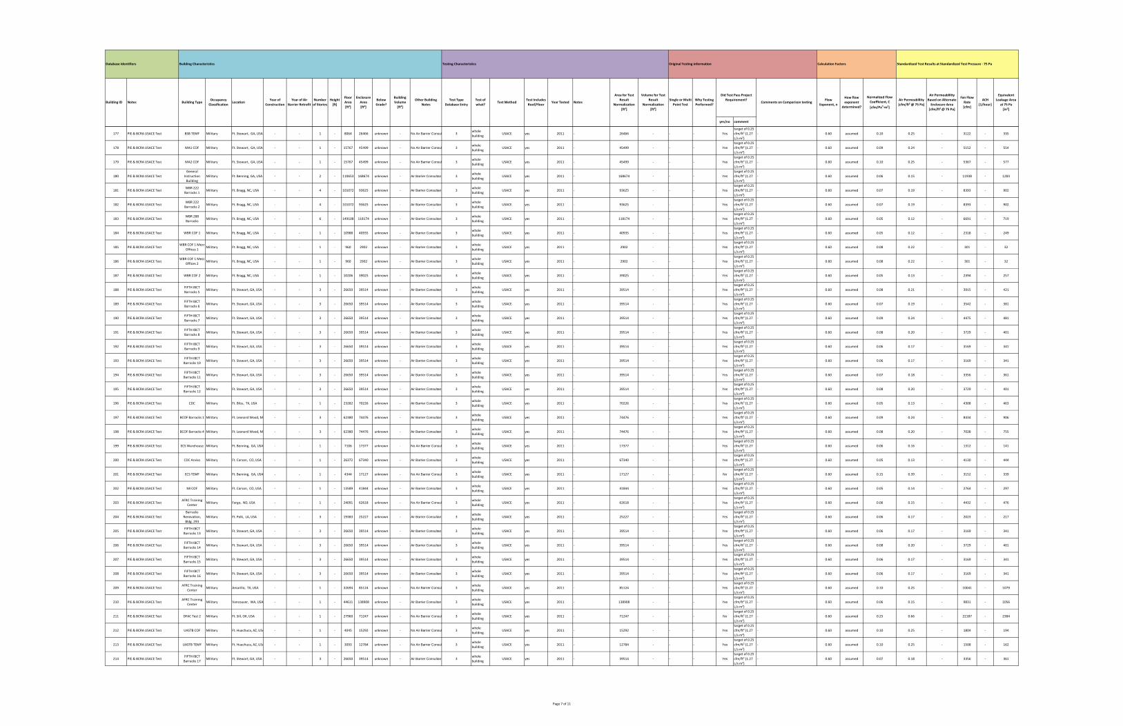
yes/no comment
How flow
exponent
determined?
Normalized Flow
Coefficient, C
[cfm/Pan∙m²]
Air Permeablility
[cfm/ft² @ 75 Pa]
Equivalent
Leakage Area
at 75 Pa
[in²]
Calculation FactorsOriginal Testing informationTesting Characteristics
Test Includes
Roof/FloorYear Tested Notes
Building CharacteristicsDatabase Identifiers
Building ID Notes Building TypeOccupancy
ClassificationLocation
Year of
Construction
Year of Air
Barrier Retrofit
Number
of Stories
Height
[ft]
Floor
Area
[ft²]
Enclosure
Area
[ft²]
Below
Grade?
Building
Volume
[ft³]
Other Building
Notes
Test Type
Database Entry
Test of
what?Test Method
Standardized Test Results at Standardized Test Pressure ‐ 75 Pa
Area for Test
Result
Normalization
[ft²]
Volume for Test
Result
Normalization
[ft³]
Comments on Comparison testingWhy Testing
Performed?
Single or Multi
Point Test
Flow
Exponent, n
Did Test Pass Project
Requirement?
Air Permeablility
Based on Alternate
Enclosure Area
[cfm/ft² @ 75 Pa]
Fan Flow
Rate
[cfm]
ACH
[1/hour]
177 PIE & BCRA USACE Test BSB TEMF Military Ft. Stewart, GA, USA ‐ ‐ 1 ‐ 8064 26466 unknown ‐ No Air Barrier Consul 3whole
buildingUSACE yes 2011 ‐ 26466 ‐ ‐ ‐ Yes
target of 0.25
cfm/ft² (1.27
L/s∙m²)
‐ 0.60 assumed 0.10 0.25 ‐ 3122 ‐ 335
178 PIE & BCRA USACE Test MA1 COF Military Ft. Stewart, GA, USA ‐ ‐ 1 ‐ 15767 45499 unknown ‐ No Air Barrier Consul 3whole
buildingUSACE yes 2011 ‐ 45499 ‐ ‐ ‐ Yes
target of 0.25
cfm/ft² (1.27
L/s∙m²)
‐ 0.60 assumed 0.09 0.24 ‐ 5152 ‐ 554
179 PIE & BCRA USACE Test MA2 COF Military Ft. Stewart, GA, USA ‐ ‐ 1 ‐ 15767 45499 unknown ‐ No Air Barrier Consul 3whole
buildingUSACE yes 2011 ‐ 45499 ‐ ‐ ‐ Yes
target of 0.25
cfm/ft² (1.27
L/s∙m²)
‐ 0.60 assumed 0.10 0.25 ‐ 5367 ‐ 577
180 PIE & BCRA USACE Test
General
Instruction
Building
Military Ft. Benning, GA, USA ‐ ‐ 2 ‐ 110653 168674 unknown ‐ Air Barrier Consultant 3whole
buildingUSACE yes 2011 ‐ 168674 ‐ ‐ ‐ Yes
target of 0.25
cfm/ft² (1.27
L/s∙m²)
‐ 0.60 assumed 0.06 0.15 ‐ 11938 ‐ 1283
181 PIE & BCRA USACE TestWBR 222
Barracks 1Military Ft. Bragg, NC, USA ‐ ‐ 4 ‐ 101072 93625 unknown ‐ Air Barrier Consultant 3
whole
buildingUSACE yes 2011 ‐ 93625 ‐ ‐ ‐ Yes
target of 0.25
cfm/ft² (1.27
L/s∙m²)
‐ 0.60 assumed 0.07 0.19 ‐ 8393 ‐ 902
182 PIE & BCRA USACE TestWBR 222
Barracks 2Military Ft. Bragg, NC, USA ‐ ‐ 4 ‐ 101072 93625 unknown ‐ Air Barrier Consultant 3
whole
buildingUSACE yes 2011 ‐ 93625 ‐ ‐ ‐ Yes
target of 0.25
cfm/ft² (1.27
L/s∙m²)
‐ 0.60 assumed 0.07 0.19 ‐ 8393 ‐ 902
183 PIE & BCRA USACE TestWBR 288
BarracksMilitary Ft. Bragg, NC, USA ‐ ‐ 6 ‐ 149108 118174 unknown ‐ Air Barrier Consultant 3
whole
buildingUSACE yes 2011 ‐ 118174 ‐ ‐ ‐ Yes
target of 0.25
cfm/ft² (1.27
L/s∙m²)
‐ 0.60 assumed 0.05 0.12 ‐ 6691 ‐ 719
184 PIE & BCRA USACE Test WBR COF 1 Military Ft. Bragg, NC, USA ‐ ‐ 1 ‐ 10988 40935 unknown ‐ Air Barrier Consultant 3whole
buildingUSACE yes 2011 ‐ 40935 ‐ ‐ ‐ Yes
target of 0.25
cfm/ft² (1.27
L/s∙m²)
‐ 0.60 assumed 0.05 0.12 ‐ 2318 ‐ 249
185 PIE & BCRA USACE TestWBR COF 1 Mezz
Offices 1Military Ft. Bragg, NC, USA ‐ ‐ 1 ‐ 960 2902 unknown ‐ Air Barrier Consultant 3
whole
buildingUSACE yes 2011 ‐ 2902 ‐ ‐ ‐ Yes
target of 0.25
cfm/ft² (1.27
L/s∙m²)
‐ 0.60 assumed 0.08 0.22 ‐ 301 ‐ 32
186 PIE & BCRA USACE TestWBR COF 1 Mezz
Offices 2Military Ft. Bragg, NC, USA ‐ ‐ 1 ‐ 960 2902 unknown ‐ Air Barrier Consultant 3
whole
buildingUSACE yes 2011 ‐ 2902 ‐ ‐ ‐ Yes
target of 0.25
cfm/ft² (1.27
L/s∙m²)
‐ 0.60 assumed 0.08 0.22 ‐ 301 ‐ 32
187 PIE & BCRA USACE Test WBR COF 2 Military Ft. Bragg, NC, USA ‐ ‐ 1 ‐ 10206 39025 unknown ‐ Air Barrier Consultant 3whole
buildingUSACE yes 2011 ‐ 39025 ‐ ‐ ‐ Yes
target of 0.25
cfm/ft² (1.27
L/s∙m²)
‐ 0.60 assumed 0.05 0.13 ‐ 2394 ‐ 257
188 PIE & BCRA USACE TestFIFTH IBCT
Barracks 5Military Ft. Stewart, GA, USA ‐ ‐ 3 ‐ 26650 39514 unknown ‐ Air Barrier Consultant 3
whole
buildingUSACE yes 2011 ‐ 39514 ‐ ‐ ‐ Yes
target of 0.25
cfm/ft² (1.27
L/s∙m²)
‐ 0.60 assumed 0.08 0.21 ‐ 3915 ‐ 421
189 PIE & BCRA USACE TestFIFTH IBCT
Barracks 6Military Ft. Stewart, GA, USA ‐ ‐ 3 ‐ 26650 39514 unknown ‐ Air Barrier Consultant 3
whole
buildingUSACE yes 2011 ‐ 39514 ‐ ‐ ‐ Yes
target of 0.25
cfm/ft² (1.27
L/s∙m²)
‐ 0.60 assumed 0.07 0.19 ‐ 3542 ‐ 381
190 PIE & BCRA USACE TestFIFTH IBCT
Barracks 7Military Ft. Stewart, GA, USA ‐ ‐ 3 ‐ 26650 39514 unknown ‐ Air Barrier Consultant 3
whole
buildingUSACE yes 2011 ‐ 39514 ‐ ‐ ‐ Yes
target of 0.25
cfm/ft² (1.27
L/s∙m²)
‐ 0.60 assumed 0.09 0.24 ‐ 4475 ‐ 481
191 PIE & BCRA USACE TestFIFTH IBCT
Barracks 8Military Ft. Stewart, GA, USA ‐ ‐ 3 ‐ 26650 39514 unknown ‐ Air Barrier Consultant 3
whole
buildingUSACE yes 2011 ‐ 39514 ‐ ‐ ‐ Yes
target of 0.25
cfm/ft² (1.27
L/s∙m²)
‐ 0.60 assumed 0.08 0.20 ‐ 3729 ‐ 401
192 PIE & BCRA USACE TestFIFTH IBCT
Barracks 9Military Ft. Stewart, GA, USA ‐ ‐ 3 ‐ 26650 39514 unknown ‐ Air Barrier Consultant 3
whole
buildingUSACE yes 2011 ‐ 39514 ‐ ‐ ‐ Yes
target of 0.25
cfm/ft² (1.27
L/s∙m²)
‐ 0.60 assumed 0.06 0.17 ‐ 3169 ‐ 341
193 PIE & BCRA USACE TestFIFTH IBCT
Barracks 10Military Ft. Stewart, GA, USA ‐ ‐ 3 ‐ 26650 39514 unknown ‐ Air Barrier Consultant 3
whole
buildingUSACE yes 2011 ‐ 39514 ‐ ‐ ‐ Yes
target of 0.25
cfm/ft² (1.27
L/s∙m²)
‐ 0.60 assumed 0.06 0.17 ‐ 3169 ‐ 341
194 PIE & BCRA USACE TestFIFTH IBCT
Barracks 11Military Ft. Stewart, GA, USA ‐ ‐ 3 ‐ 26650 39514 unknown ‐ Air Barrier Consultant 3
whole
buildingUSACE yes 2011 ‐ 39514 ‐ ‐ ‐ Yes
target of 0.25
cfm/ft² (1.27
L/s∙m²)
‐ 0.60 assumed 0.07 0.18 ‐ 3356 ‐ 361
195 PIE & BCRA USACE TestFIFTH IBCT
Barracks 12Military Ft. Stewart, GA, USA ‐ ‐ 3 ‐ 26650 39514 unknown ‐ Air Barrier Consultant 3
whole
buildingUSACE yes 2011 ‐ 39514 ‐ ‐ ‐ Yes
target of 0.25
cfm/ft² (1.27
L/s∙m²)
‐ 0.60 assumed 0.08 0.20 ‐ 3729 ‐ 401
196 PIE & BCRA USACE Test CDC Military Ft. Bliss, TX, USA ‐ ‐ 1 ‐ 23282 70226 unknown ‐ Air Barrier Consultant 3whole
buildingUSACE yes 2011 ‐ 70226 ‐ ‐ ‐ Yes
target of 0.25
cfm/ft² (1.27
L/s∙m²)
‐ 0.60 assumed 0.05 0.13 ‐ 4308 ‐ 463
197 PIE & BCRA USACE Test BCOF Barracks 1 Military Ft. Leonard Wood, MO ‐ ‐ 3 ‐ 62380 74476 unknown ‐ Air Barrier Consultant 3whole
buildingUSACE yes 2011 ‐ 74476 ‐ ‐ ‐ Yes
target of 0.25
cfm/ft² (1.27
L/s∙m²)
‐ 0.60 assumed 0.09 0.24 ‐ 8434 ‐ 906
198 PIE & BCRA USACE Test BCOF Barracks 4 Military Ft. Leonard Wood, MO ‐ ‐ 3 ‐ 62380 74476 unknown ‐ Air Barrier Consultant 3whole
buildingUSACE yes 2011 ‐ 74476 ‐ ‐ ‐ Yes
target of 0.25
cfm/ft² (1.27
L/s∙m²)
‐ 0.60 assumed 0.08 0.20 ‐ 7028 ‐ 755
199 PIE & BCRA USACE Test ECS Warehouse Military Ft. Benning, GA, USA ‐ ‐ 1 ‐ 7106 17377 unknown ‐ No Air Barrier Consul 3whole
buildingUSACE yes 2011 ‐ 17377 ‐ ‐ ‐ Yes
target of 0.25
cfm/ft² (1.27
L/s∙m²)
‐ 0.60 assumed 0.06 0.16 ‐ 1312 ‐ 141
200 PIE & BCRA USACE Test CDC Arviso Military Ft. Carson, CO, USA ‐ ‐ 1 ‐ 26372 67340 unknown ‐ Air Barrier Consultant 3whole
buildingUSACE yes 2011 ‐ 67340 ‐ ‐ ‐ Yes
target of 0.25
cfm/ft² (1.27
L/s∙m²)
‐ 0.60 assumed 0.05 0.13 ‐ 4130 ‐ 444
201 PIE & BCRA USACE Test ECS TEMF Military Ft. Benning, GA, USA ‐ ‐ 1 ‐ 4344 17127 unknown ‐ No Air Barrier Consul 3whole
buildingUSACE yes 2011 ‐ 17127 ‐ ‐ ‐ No
target of 0.25
cfm/ft² (1.27
L/s∙m²)
‐ 0.60 assumed 0.15 0.39 ‐ 3152 ‐ 339
202 PIE & BCRA USACE Test MI COF Military Ft. Carson, CO, USA ‐ ‐ 1 ‐ 13589 41844 unknown ‐ Air Barrier Consultant 3whole
buildingUSACE yes 2011 ‐ 41844 ‐ ‐ ‐ Yes
target of 0.25
cfm/ft² (1.27
L/s∙m²)
‐ 0.60 assumed 0.05 0.14 ‐ 2764 ‐ 297
203 PIE & BCRA USACE TestAFRC Training
CenterMilitary Fargo, ND, USA ‐ ‐ 1 ‐ 24091 62618 unknown ‐ No Air Barrier Consul 3
whole
buildingUSACE yes 2011 ‐ 62618 ‐ ‐ ‐ Yes
target of 0.25
cfm/ft² (1.27
L/s∙m²)
‐ 0.60 assumed 0.06 0.15 ‐ 4432 ‐ 476
204 PIE & BCRA USACE Test
Barracks
Renovation,
Bldg. 293
Military Ft. Polk, LA, USA ‐ ‐ 3 ‐ 19383 25227 unknown ‐ Air Barrier Consultant 3whole
buildingUSACE yes 2011 ‐ 25227 ‐ ‐ ‐ Yes
target of 0.25
cfm/ft² (1.27
L/s∙m²)
‐ 0.60 assumed 0.06 0.17 ‐ 2023 ‐ 217
205 PIE & BCRA USACE TestFIFTH IBCT
Barracks 13Military Ft. Stewart, GA, USA ‐ ‐ 3 ‐ 26650 39514 unknown ‐ Air Barrier Consultant 3
whole
buildingUSACE yes 2011 ‐ 39514 ‐ ‐ ‐ Yes
target of 0.25
cfm/ft² (1.27
L/s∙m²)
‐ 0.60 assumed 0.06 0.17 ‐ 3169 ‐ 341
206 PIE & BCRA USACE TestFIFTH IBCT
Barracks 14Military Ft. Stewart, GA, USA ‐ ‐ 3 ‐ 26650 39514 unknown ‐ Air Barrier Consultant 3
whole
buildingUSACE yes 2011 ‐ 39514 ‐ ‐ ‐ Yes
target of 0.25
cfm/ft² (1.27
L/s∙m²)
‐ 0.60 assumed 0.08 0.20 ‐ 3729 ‐ 401
207 PIE & BCRA USACE TestFIFTH IBCT
Barracks 15Military Ft. Stewart, GA, USA ‐ ‐ 3 ‐ 26650 39514 unknown ‐ Air Barrier Consultant 3
whole
buildingUSACE yes 2011 ‐ 39514 ‐ ‐ ‐ Yes
target of 0.25
cfm/ft² (1.27
L/s∙m²)
‐ 0.60 assumed 0.06 0.17 ‐ 3169 ‐ 341
208 PIE & BCRA USACE TestFIFTH IBCT
Barracks 16Military Ft. Stewart, GA, USA ‐ ‐ 3 ‐ 26650 39514 unknown ‐ Air Barrier Consultant 3
whole
buildingUSACE yes 2011 ‐ 39514 ‐ ‐ ‐ Yes
target of 0.25
cfm/ft² (1.27
L/s∙m²)
‐ 0.60 assumed 0.06 0.17 ‐ 3169 ‐ 341
209 PIE & BCRA USACE TestAFRC Training
CenterMilitary Amarillo, TX, USA ‐ ‐ 1 ‐ 32694 85124 unknown ‐ No Air Barrier Consul 3
whole
buildingUSACE yes 2011 ‐ 85124 ‐ ‐ ‐ Yes
target of 0.25
cfm/ft² (1.27
L/s∙m²)
‐ 0.60 assumed 0.10 0.25 ‐ 10041 ‐ 1079
210 PIE & BCRA USACE TestAFRC Training
CenterMilitary Vancouver, WA, USA ‐ ‐ 1 ‐ 44611 138908 unknown ‐ Air Barrier Consultant 3
whole
buildingUSACE yes 2011 ‐ 138908 ‐ ‐ ‐ Yes
target of 0.25
cfm/ft² (1.27
L/s∙m²)
‐ 0.60 assumed 0.06 0.15 ‐ 9831 ‐ 1056
211 PIE & BCRA USACE Test DFAC Test 2 Military Ft. Sill, OK, USA ‐ ‐ 1 ‐ 27960 71247 unknown ‐ No Air Barrier Consul 3whole
buildingUSACE yes 2011 ‐ 71247 ‐ ‐ ‐ No
target of 0.25
cfm/ft² (1.27
L/s∙m²)
‐ 0.60 assumed 0.25 0.66 ‐ 22187 ‐ 2384
212 PIE & BCRA USACE Test UASTB COF Military Ft. Huachuca, AZ, USA ‐ ‐ 1 ‐ 4045 15292 unknown ‐ No Air Barrier Consul 3whole
buildingUSACE yes 2011 ‐ 15292 ‐ ‐ ‐ Yes
target of 0.25
cfm/ft² (1.27
L/s∙m²)
‐ 0.60 assumed 0.10 0.25 ‐ 1804 ‐ 194
213 PIE & BCRA USACE Test UASTB TEMF Military Ft. Huachuca, AZ, USA ‐ ‐ 1 ‐ 3093 12784 unknown ‐ No Air Barrier Consul 3whole
buildingUSACE yes 2011 ‐ 12784 ‐ ‐ ‐ Yes
target of 0.25
cfm/ft² (1.27
L/s∙m²)
‐ 0.60 assumed 0.10 0.25 ‐ 1508 ‐ 162
214 PIE & BCRA USACE TestFIFTH IBCT
Barracks 17Military Ft. Stewart, GA, USA ‐ ‐ 3 ‐ 26650 39514 unknown ‐ Air Barrier Consultant 3
whole
buildingUSACE yes 2011 ‐ 39514 ‐ ‐ ‐ Yes
target of 0.25
cfm/ft² (1.27
L/s∙m²)
‐ 0.60 assumed 0.07 0.18 ‐ 3356 ‐ 361
Page 7 of 11
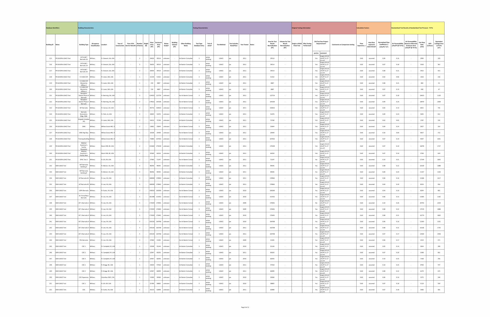
yes/no comment
How flow
exponent
determined?
Normalized Flow
Coefficient, C
[cfm/Pan∙m²]
Air Permeablility
[cfm/ft² @ 75 Pa]
Equivalent
Leakage Area
at 75 Pa
[in²]
Calculation FactorsOriginal Testing informationTesting Characteristics
Test Includes
Roof/FloorYear Tested Notes
Building CharacteristicsDatabase Identifiers
Building ID Notes Building TypeOccupancy
ClassificationLocation
Year of
Construction
Year of Air
Barrier Retrofit
Number
of Stories
Height
[ft]
Floor
Area
[ft²]
Enclosure
Area
[ft²]
Below
Grade?
Building
Volume
[ft³]
Other Building
Notes
Test Type
Database Entry
Test of
what?Test Method
Standardized Test Results at Standardized Test Pressure ‐ 75 Pa
Area for Test
Result
Normalization
[ft²]
Volume for Test
Result
Normalization
[ft³]
Comments on Comparison testingWhy Testing
Performed?
Single or Multi
Point Test
Flow
Exponent, n
Did Test Pass Project
Requirement?
Air Permeablility
Based on Alternate
Enclosure Area
[cfm/ft² @ 75 Pa]
Fan Flow
Rate
[cfm]
ACH
[1/hour]
215 PIE & BCRA USACE TestFIFTH IBCT
Barracks 18Military Ft. Stewart, GA, USA ‐ ‐ 3 ‐ 26650 39514 unknown ‐ Air Barrier Consultant 3
whole
buildingUSACE yes 2011 ‐ 39514 ‐ ‐ ‐ Yes
target of 0.25
cfm/ft² (1.27
L/s∙m²)
‐ 0.60 assumed 0.06 0.16 ‐ 2983 ‐ 320
216 PIE & BCRA USACE TestFIFTH IBCT
Barracks 19Military Ft. Stewart, GA, USA ‐ ‐ 3 ‐ 26650 39514 unknown ‐ Air Barrier Consultant 3
whole
buildingUSACE yes 2011 ‐ 39514 ‐ ‐ ‐ Yes
target of 0.25
cfm/ft² (1.27
L/s∙m²)
‐ 0.60 assumed 0.07 0.18 ‐ 3356 ‐ 361
217 PIE & BCRA USACE TestFIFTH IBCT
Barracks 20Military Ft. Stewart, GA, USA ‐ ‐ 3 ‐ 26650 39514 unknown ‐ Air Barrier Consultant 3
whole
buildingUSACE yes 2011 ‐ 39514 ‐ ‐ ‐ Yes
target of 0.25
cfm/ft² (1.27
L/s∙m²)
‐ 0.60 assumed 0.08 0.21 ‐ 3915 ‐ 421
218 PIE & BCRA USACE Test 5‐5 ADA COF Military Ft. Lewis, WA, USA ‐ ‐ 1 ‐ 15130 51352 unknown ‐ Air Barrier Consultant 3whole
buildingUSACE yes 2011 ‐ 51352 ‐ ‐ ‐ Yes
target of 0.25
cfm/ft² (1.27
L/s∙m²)
‐ 0.60 assumed 0.02 0.06 ‐ 1454 ‐ 156
219 PIE & BCRA USACE Test
5‐5 ADA COF
Mezzanine
Offices 1
Military Ft. Lewis, WA, USA ‐ ‐ 1 ‐ 150 4887 unknown ‐ Air Barrier Consultant 3whole
buildingUSACE yes 2011 ‐ 4887 ‐ ‐ ‐ Yes
target of 0.25
cfm/ft² (1.27
L/s∙m²)
‐ 0.60 assumed 0.08 0.21 ‐ 484 ‐ 52
220 PIE & BCRA USACE Test
5‐5 ADA COF
Mezzanine
Offices 2
Military Ft. Lewis, WA, USA ‐ ‐ 1 ‐ 150 4887 unknown ‐ Air Barrier Consultant 3whole
buildingUSACE yes 2011 ‐ 4887 ‐ ‐ ‐ Yes
target of 0.25
cfm/ft² (1.27
L/s∙m²)
‐ 0.60 assumed 0.07 0.19 ‐ 438 ‐ 47
221 PIE & BCRA USACE Test
Reception
Station Phase III
Barracks
Military Ft. Benning, GA, USA ‐ ‐ 3 ‐ 124923 122724 unknown ‐ No Air Barrier Consul 3whole
buildingUSACE yes 2011 ‐ 122724 ‐ ‐ ‐ Yes
target of 0.25
cfm/ft² (1.27
L/s∙m²)
‐ 0.60 assumed 0.07 0.18 ‐ 10423 ‐ 1120
222 PIE & BCRA USACE Test
Reception
Station Phase II
Barracks
Military Ft. Benning, GA, USA ‐ ‐ 3 ‐ 179631 164106 unknown ‐ No Air Barrier Consul 3whole
buildingUSACE yes 2011 ‐ 164106 ‐ ‐ ‐ Yes
target of 0.25
cfm/ft² (1.27
L/s∙m²)
‐ 0.60 assumed 0.09 0.24 ‐ 18970 ‐ 2038
223 PIE & BCRA USACE Test WT Barracks Military Ft. Carson, CO, USA ‐ ‐ 4 ‐ 99776 104923 unknown ‐ No Air Barrier Consul 3whole
buildingUSACE yes 2011 ‐ 104923 ‐ ‐ ‐ Yes
target of 0.25
cfm/ft² (1.27
L/s∙m²)
‐ 0.60 assumed 0.05 0.14 ‐ 6931 ‐ 745
224 PIE & BCRA USACE Test
Barracks
Renovation,
Bldg, 2386
Military Ft. Polk, LA, USA ‐ ‐ 3 ‐ 34605 52476 unknown ‐ Air Barrier Consultant 3whole
buildingUSACE yes 2011 ‐ 52476 ‐ ‐ ‐ Yes
target of 0.25
cfm/ft² (1.27
L/s∙m²)
‐ 0.60 assumed 0.09 0.23 ‐ 5695 ‐ 612
225 PIE & BCRA USACE TestBrigade Complex
HQMilitary Ft. Lewis, WA, USA ‐ ‐ 2 ‐ 54415 75760 unknown ‐ Air Barrier Consultant 3
whole
buildingUSACE yes 2011 ‐ 75760 ‐ ‐ ‐ Yes
target of 0.25
cfm/ft² (1.27
L/s∙m²)
‐ 0.60 assumed 0.02 0.05 ‐ 1787 ‐ 192
226 PIE & BCRA USACE Test OMS Military Willow Grove ARC, PA ‐ ‐ 2 ‐ 13862 25844 unknown ‐ No Air Barrier Consul 3whole
buildingUSACE yes 2011 ‐ 25844 ‐ ‐ ‐ Yes
target of 0.25
cfm/ft² (1.27
L/s∙m²)
‐ 0.60 assumed 0.09 0.24 ‐ 2927 ‐ 314
227 PIE & BCRA USACE Test OMS High Bay Military Willow Grove ARC, PA ‐ ‐ 1 ‐ 10338 20449 unknown ‐ No Air Barrier Consul 3whole
buildingUSACE yes 2011 ‐ 20449 ‐ ‐ ‐ Yes
target of 0.25
cfm/ft² (1.27
L/s∙m²)
‐ 0.60 assumed 0.26 0.69 ‐ 6657 ‐ 715
228 PIE & BCRA USACE Test Training Building Military Willow Grove ARC, PA ‐ ‐ 1 ‐ 73080 107053 unknown ‐ No Air Barrier Consul 3whole
buildingUSACE yes 2011 ‐ 107053 ‐ ‐ ‐ Yes
target of 0.25
cfm/ft² (1.27
L/s∙m²)
‐ 0.60 assumed 0.07 0.19 ‐ 9597 ‐ 1031
229 PIE & BCRA USACE Test
Medical
Examiner's
Facility
Rnovation
Military Dover AFB, DE, USA ‐ ‐ 2 ‐ 152684 179349 unknown ‐ Air Barrier Consultant 3whole
buildingUSACE yes 2011 ‐ 179349 ‐ ‐ ‐ Yes
target of 0.25
cfm/ft² (1.27
L/s∙m²)
‐ 0.60 assumed 0.07 0.19 ‐ 16078 ‐ 1727
230 PIE & BCRA USACE Test
Medical
Examiner's
Facility New
Military Dover AFB, DE, USA ‐ ‐ 2 ‐ 32560 64254 unknown ‐ Air Barrier Consultant 3whole
buildingUSACE yes 2011 ‐ 64254 ‐ ‐ ‐ Yes
target of 0.25
cfm/ft² (1.27
L/s∙m²)
‐ 0.60 assumed 0.07 0.19 ‐ 5760 ‐ 619
231 PIE & BCRA USACE Test DFAC Test 3 Military Ft. Sill, OK, USA ‐ ‐ 1 ‐ 27960 71247 unknown ‐ No Air Barrier Consul 3whole
buildingUSACE yes 2011 ‐ 71247 ‐ ‐ ‐ No
target of 0.25
cfm/ft² (1.27
L/s∙m²)
‐ 0.60 assumed 0.19 0.51 ‐ 17144 ‐ 1842
232 SEM USACE TestWIT Barracks
Building AMilitary Ft. Belvoir, VA, USA ‐ ‐ 4 ‐ 98296 99595 unknown ‐ Air Barrier Consultant 3
whole
buildingUSACE yes 2011 ‐ 99595 ‐ ‐ ‐ Yes
target of 0.25
cfm/ft² (1.27
L/s∙m²)
‐ 0.60 assumed 0.08 0.22 ‐ 10130 ‐ 1088
233 SEM USACE TestWIT Barracks
Building BMilitary Ft. Belvoir, VA, USA ‐ ‐ 4 ‐ 98296 99595 unknown ‐ Air Barrier Consultant 3
whole
buildingUSACE yes 2011 ‐ 99595 ‐ ‐ ‐ Yes
target of 0.25
cfm/ft² (1.27
L/s∙m²)
‐ 0.60 assumed 0.09 0.24 ‐ 11357 ‐ 1220
234 SEM USACE Test AIT Barracks #1 Military Ft. Lee, VA, USA ‐ ‐ 5 ‐ 180000 178962 unknown ‐ Air Barrier Consultant 3whole
buildingUSACE yes 2011 ‐ 178962 ‐ ‐ ‐ Yes
target of 0.25
cfm/ft² (1.27
L/s∙m²)
‐ 0.60 assumed 0.06 0.16 ‐ 13186 ‐ 1417
235 SEM USACE Test AIT Barracks #2 Military Ft. Lee, VA, USA ‐ ‐ 5 ‐ 180000 178962 unknown ‐ Air Barrier Consultant 3whole
buildingUSACE yes 2011 ‐ 178962 ‐ ‐ ‐ Yes
target of 0.25
cfm/ft² (1.27
L/s∙m²)
‐ 0.60 assumed 0.04 0.10 ‐ 8529 ‐ 916
236 SEM USACE Test UEPH Barracks Military Ft. Eustis, VA, USA ‐ ‐ 3 ‐ 140010 169260 unknown ‐ No Air Barrier Consul 3whole
buildingUSACE yes 2010 ‐ 169260 ‐ ‐ ‐ Yes
target of 0.25
cfm/ft² (1.27
L/s∙m²)
‐ 0.60 assumed 0.04 0.10 ‐ 8294 ‐ 891
237 SEM USACE TestAir Force/Navy
BarracksMilitary Ft. Lee, VA, USA ‐ ‐ 5 ‐ 181498 151952 unknown ‐ No Air Barrier Consul 3
whole
buildingUSACE yes 2010 ‐ 151952 ‐ ‐ ‐ Yes
target of 0.25
cfm/ft² (1.27
L/s∙m²)
‐ 0.60 assumed 0.06 0.15 ‐ 11005 ‐ 1182
238 SEM USACE Test AIT 1 Barracks‐1 Military Ft. Lee, VA, USA ‐ ‐ 5 ‐ 173929 170401 unknown ‐ No Air Barrier Consul 3whole
buildingUSACE yes 2009 ‐ 170401 ‐ ‐ ‐ No
target of 0.25
cfm/ft² (1.27
L/s∙m²)
‐ 0.60 assumed 0.10 0.26 ‐ 20793 ‐ 2234
239 SEM USACE Test AIT 1 Barracks‐2 Military Ft. Lee, VA, USA ‐ ‐ 5 ‐ 173929 170401 unknown ‐ No Air Barrier Consul 3whole
buildingUSACE yes 2009 ‐ 170401 ‐ ‐ ‐ Yes
target of 0.25
cfm/ft² (1.27
L/s∙m²)
‐ 0.60 assumed 0.08 0.22 ‐ 17570 ‐ 1888
240 SEM USACE Test AIT 1 Barracks‐3 Military Ft. Lee, VA, USA ‐ ‐ 5 ‐ 173929 170401 unknown ‐ No Air Barrier Consul 3whole
buildingUSACE yes 2010 ‐ 170401 ‐ ‐ ‐ Yes
target of 0.25
cfm/ft² (1.27
L/s∙m²)
‐ 0.60 assumed 0.08 0.21 ‐ 16774 ‐ 1802
241 SEM USACE Test AIT 2 Barracks‐4 Military Ft. Lee, VA, USA ‐ ‐ 5 ‐ 193103 164768 unknown ‐ No Air Barrier Consul 3whole
buildingUSACE yes 2010 ‐ 164768 ‐ ‐ ‐ Yes
target of 0.25
cfm/ft² (1.27
L/s∙m²)
‐ 0.60 assumed 0.06 0.16 ‐ 12393 ‐ 1331
242 SEM USACE Test AIT 2 Barracks‐5 Military Ft. Lee, VA, USA ‐ ‐ 5 ‐ 193103 164768 unknown ‐ No Air Barrier Consul 3whole
buildingUSACE yes 2011 ‐ 164768 ‐ ‐ ‐ Yes
target of 0.25
cfm/ft² (1.27
L/s∙m²)
‐ 0.60 assumed 0.08 0.21 ‐ 16146 ‐ 1735
243 SEM USACE Test AIT 2 Barracks‐6 Military Ft. Lee, VA, USA ‐ ‐ 5 ‐ 193103 164768 unknown ‐ No Air Barrier Consul 3whole
buildingUSACE yes 2011 ‐ 164768 ‐ ‐ ‐ Yes
target of 0.25
cfm/ft² (1.27
L/s∙m²)
‐ 0.60 assumed 0.07 0.17 ‐ 13569 ‐ 1458
244 SEM USACE Test POL Barracks Military Ft. Lee, VA, USA ‐ ‐ 3 ‐ 27000 31305 unknown ‐ No Air Barrier Consul 3whole
buildingUSACE yes 2009 ‐ 31305 ‐ ‐ ‐ Yes
target of 0.25
cfm/ft² (1.27
L/s∙m²)
‐ 0.60 assumed 0.06 0.17 ‐ 2519 ‐ 271
245 SEM USACE Test CDC 1 Military Ft. Campbell, KY, USA ‐ ‐ 1 ‐ 23508 55144 unknown ‐ Air Barrier Consultant 3whole
buildingUSACE yes 2010 ‐ 55144 ‐ ‐ ‐ Yes
target of 0.25
cfm/ft² (1.27
L/s∙m²)
‐ 0.60 assumed 0.05 0.14 ‐ 3634 ‐ 390
246 SEM USACE Test CDC 2 Military Ft. Campbell, KY, USA ‐ ‐ 1 ‐ 22947 60293 unknown ‐ Air Barrier Consultant 3whole
buildingUSACE yes 2011 ‐ 60293 ‐ ‐ ‐ Yes
target of 0.25
cfm/ft² (1.27
L/s∙m²)
‐ 0.60 assumed 0.07 0.20 ‐ 5598 ‐ 601
247 SEM USACE Test CDC 3 Military Ft. Campbell, KY, USA ‐ ‐ 1 ‐ 22947 60293 unknown ‐ Air Barrier Consultant 3whole
buildingUSACE yes 2010 ‐ 60293 ‐ ‐ ‐ Yes
target of 0.25
cfm/ft² (1.27
L/s∙m²)
‐ 0.60 assumed 0.10 0.25 ‐ 7108 ‐ 764
248 SEM USACE Test CDC 1 Military Ft. Bragg, NC, USA ‐ ‐ 1 ‐ 23034 57418 unknown ‐ Air Barrier Consultant 3whole
buildingUSACE yes 2011 ‐ 57418 ‐ ‐ ‐ Yes
target of 0.25
cfm/ft² (1.27
L/s∙m²)
‐ 0.60 assumed 0.10 0.25 ‐ 6764 ‐ 727
249 SEM USACE Test CDC 2 Military Ft. Bragg, NC, USA ‐ ‐ 1 ‐ 22947 60099 unknown ‐ Air Barrier Consultant 3whole
buildingUSACE yes 2011 ‐ 60099 ‐ ‐ ‐ Yes
target of 0.25
cfm/ft² (1.27
L/s∙m²)
‐ 0.60 assumed 0.08 0.22 ‐ 6279 ‐ 675
250 SEM USACE Test CDC Expansion Military Columbus DSCC, OH, ‐ ‐ 1 ‐ 13300 30360 unknown ‐ Air Barrier Consultant 3whole
buildingUSACE yes 2010 ‐ 30360 ‐ ‐ ‐ Yes
target of 0.25
cfm/ft² (1.27
L/s∙m²)
‐ 0.60 assumed 0.06 0.16 ‐ 2275 ‐ 244
251 SEM USACE Test CDC 1 Military Ft. Sill, OK, USA ‐ ‐ 1 ‐ 25789 58805 unknown ‐ Air Barrier Consultant 3whole
buildingUSACE yes 2010 ‐ 58805 ‐ ‐ ‐ Yes
target of 0.25
cfm/ft² (1.27
L/s∙m²)
‐ 0.60 assumed 0.07 0.18 ‐ 5118 ‐ 550
252 SEM USACE Test CDC Military Ft. Eustis, VA, USA ‐ ‐ 1 ‐ 26123 63898 unknown ‐ Air Barrier Consultant 3whole
buildingUSACE yes 2011 ‐ 63898 ‐ ‐ ‐ Yes
target of 0.25
cfm/ft² (1.27
L/s∙m²)
‐ 0.60 assumed 0.07 0.18 ‐ 5406 ‐ 581
Page 8 of 11
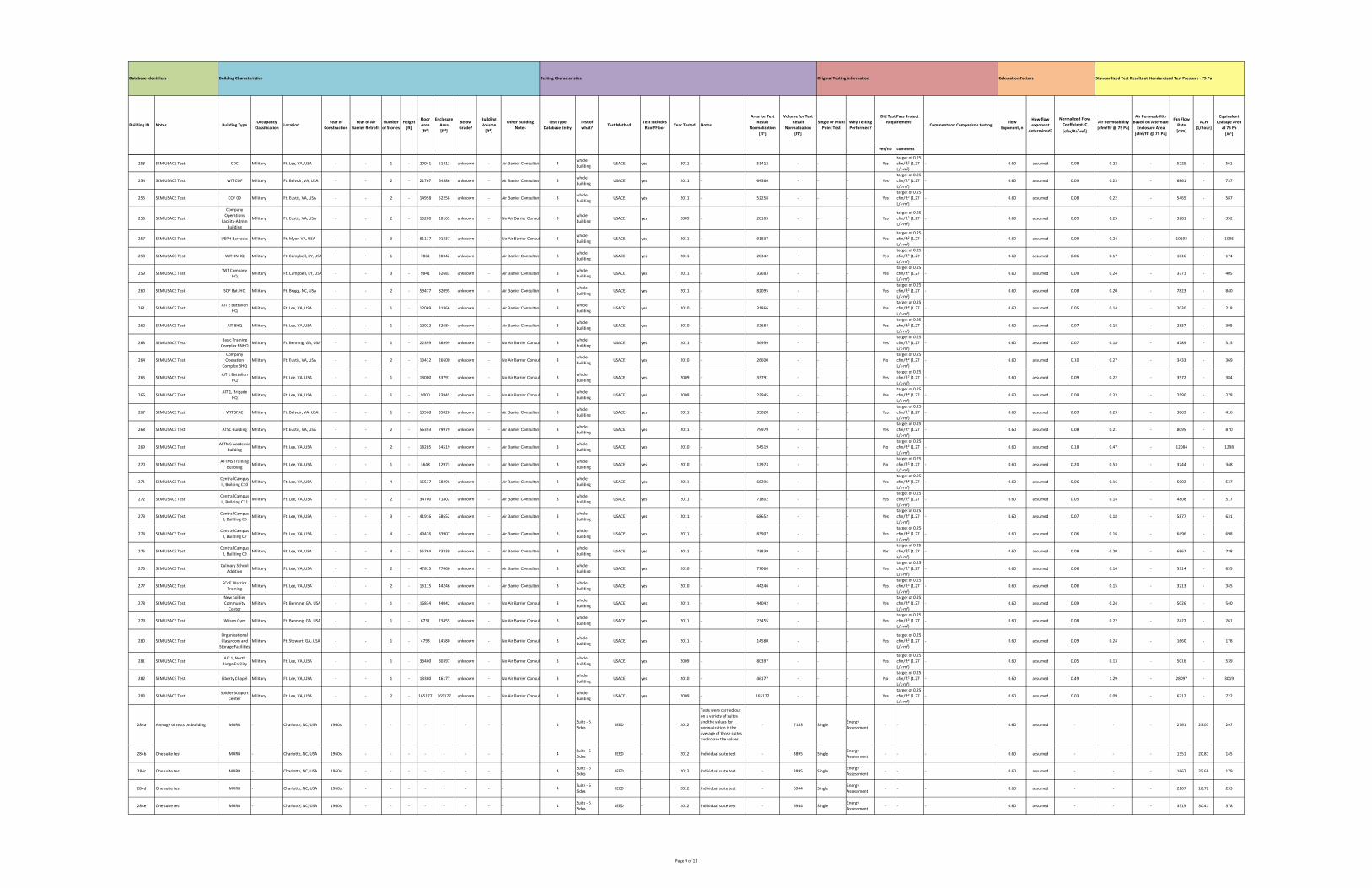
yes/no comment
How flow
exponent
determined?
Normalized Flow
Coefficient, C
[cfm/Pan∙m²]
Air Permeablility
[cfm/ft² @ 75 Pa]
Equivalent
Leakage Area
at 75 Pa
[in²]
Calculation FactorsOriginal Testing informationTesting Characteristics
Test Includes
Roof/FloorYear Tested Notes
Building CharacteristicsDatabase Identifiers
Building ID Notes Building TypeOccupancy
ClassificationLocation
Year of
Construction
Year of Air
Barrier Retrofit
Number
of Stories
Height
[ft]
Floor
Area
[ft²]
Enclosure
Area
[ft²]
Below
Grade?
Building
Volume
[ft³]
Other Building
Notes
Test Type
Database Entry
Test of
what?Test Method
Standardized Test Results at Standardized Test Pressure ‐ 75 Pa
Area for Test
Result
Normalization
[ft²]
Volume for Test
Result
Normalization
[ft³]
Comments on Comparison testingWhy Testing
Performed?
Single or Multi
Point Test
Flow
Exponent, n
Did Test Pass Project
Requirement?
Air Permeablility
Based on Alternate
Enclosure Area
[cfm/ft² @ 75 Pa]
Fan Flow
Rate
[cfm]
ACH
[1/hour]
253 SEM USACE Test CDC Military Ft. Lee, VA, USA ‐ ‐ 1 ‐ 20041 51412 unknown ‐ Air Barrier Consultant 3whole
buildingUSACE yes 2011 ‐ 51412 ‐ ‐ ‐ Yes
target of 0.25
cfm/ft² (1.27
L/s∙m²)
‐ 0.60 assumed 0.08 0.22 ‐ 5225 ‐ 561
254 SEM USACE Test WIT COF Military Ft. Belvoir, VA, USA ‐ ‐ 2 ‐ 21767 64586 unknown ‐ Air Barrier Consultant 3whole
buildingUSACE yes 2011 ‐ 64586 ‐ ‐ ‐ Yes
target of 0.25
cfm/ft² (1.27
L/s∙m²)
‐ 0.60 assumed 0.09 0.23 ‐ 6861 ‐ 737
255 SEM USACE Test COF 09 Military Ft. Eustis, VA, USA ‐ ‐ 2 ‐ 14958 52258 unknown ‐ Air Barrier Consultant 3whole
buildingUSACE yes 2011 ‐ 52258 ‐ ‐ ‐ Yes
target of 0.25
cfm/ft² (1.27
L/s∙m²)
‐ 0.60 assumed 0.08 0.22 ‐ 5465 ‐ 587
256 SEM USACE Test
Company
Operations
Facility‐Admin
Building
Military Ft. Eustis, VA, USA ‐ ‐ 2 ‐ 16200 28165 unknown ‐ No Air Barrier Consul 3whole
buildingUSACE yes 2009 ‐ 28165 ‐ ‐ ‐ Yes
target of 0.25
cfm/ft² (1.27
L/s∙m²)
‐ 0.60 assumed 0.09 0.25 ‐ 3281 ‐ 352
257 SEM USACE Test UEPH Barracks Military Ft. Myer, VA, USA ‐ ‐ 3 ‐ 81117 91837 unknown ‐ No Air Barrier Consul 3whole
buildingUSACE yes 2011 ‐ 91837 ‐ ‐ ‐ Yes
target of 0.25
cfm/ft² (1.27
L/s∙m²)
‐ 0.60 assumed 0.09 0.24 ‐ 10193 ‐ 1095
258 SEM USACE Test WIT BNHQ Military Ft. Campbell, KY, USA ‐ ‐ 1 ‐ 7861 20342 unknown ‐ Air Barrier Consultant 3whole
buildingUSACE yes 2011 ‐ 20342 ‐ ‐ ‐ Yes
target of 0.25
cfm/ft² (1.27
L/s∙m²)
‐ 0.60 assumed 0.06 0.17 ‐ 1616 ‐ 174
259 SEM USACE TestWIT Company
HQMilitary Ft. Campbell, KY, USA ‐ ‐ 3 ‐ 9841 32683 unknown ‐ Air Barrier Consultant 3
whole
buildingUSACE yes 2011 ‐ 32683 ‐ ‐ ‐ Yes
target of 0.25
cfm/ft² (1.27
L/s∙m²)
‐ 0.60 assumed 0.09 0.24 ‐ 3771 ‐ 405
260 SEM USACE Test SOF Bat. HQ Military Ft. Bragg, NC, USA ‐ ‐ 2 ‐ 59477 82095 unknown ‐ Air Barrier Consultant 3whole
buildingUSACE yes 2011 ‐ 82095 ‐ ‐ ‐ Yes
target of 0.25
cfm/ft² (1.27
L/s∙m²)
‐ 0.60 assumed 0.08 0.20 ‐ 7823 ‐ 840
261 SEM USACE TestAIT 2 Battalion
HQMilitary Ft. Lee, VA, USA ‐ ‐ 1 ‐ 12069 31866 unknown ‐ Air Barrier Consultant 3
whole
buildingUSACE yes 2010 ‐ 31866 ‐ ‐ ‐ Yes
target of 0.25
cfm/ft² (1.27
L/s∙m²)
‐ 0.60 assumed 0.05 0.14 ‐ 2030 ‐ 218
262 SEM USACE Test AIT BHQ Military Ft. Lee, VA, USA ‐ ‐ 1 ‐ 12022 32684 unknown ‐ Air Barrier Consultant 3whole
buildingUSACE yes 2010 ‐ 32684 ‐ ‐ ‐ Yes
target of 0.25
cfm/ft² (1.27
L/s∙m²)
‐ 0.60 assumed 0.07 0.18 ‐ 2837 ‐ 305
263 SEM USACE TestBasic Training
Complex BNHQMilitary Ft. Benning, GA, USA ‐ ‐ 1 ‐ 22399 56999 unknown ‐ No Air Barrier Consul 3
whole
buildingUSACE yes 2011 ‐ 56999 ‐ ‐ ‐ Yes
target of 0.25
cfm/ft² (1.27
L/s∙m²)
‐ 0.60 assumed 0.07 0.18 ‐ 4789 ‐ 515
264 SEM USACE Test
Company
Operation
Complex BHQ
Military Ft. Eustis, VA, USA ‐ ‐ 2 ‐ 13432 26600 unknown ‐ No Air Barrier Consul 3whole
buildingUSACE yes 2010 ‐ 26600 ‐ ‐ ‐ No
target of 0.25
cfm/ft² (1.27
L/s∙m²)
‐ 0.60 assumed 0.10 0.27 ‐ 3433 ‐ 369
265 SEM USACE TestAIT 1 Battalion
HQMilitary Ft. Lee, VA, USA ‐ ‐ 1 ‐ 13000 33791 unknown ‐ No Air Barrier Consul 3
whole
buildingUSACE yes 2009 ‐ 33791 ‐ ‐ ‐ Yes
target of 0.25
cfm/ft² (1.27
L/s∙m²)
‐ 0.60 assumed 0.09 0.22 ‐ 3572 ‐ 384
266 SEM USACE TestAIT 1, Brigade
HQMilitary Ft. Lee, VA, USA ‐ ‐ 1 ‐ 9000 23945 unknown ‐ No Air Barrier Consul 3
whole
buildingUSACE yes 2009 ‐ 23945 ‐ ‐ ‐ Yes
target of 0.25
cfm/ft² (1.27
L/s∙m²)
‐ 0.60 assumed 0.09 0.23 ‐ 2590 ‐ 278
267 SEM USACE Test WIT SFAC Military Ft. Belvoir, VA, USA ‐ ‐ 1 ‐ 13568 35020 unknown ‐ Air Barrier Consultant 3whole
buildingUSACE yes 2011 ‐ 35020 ‐ ‐ ‐ Yes
target of 0.25
cfm/ft² (1.27
L/s∙m²)
‐ 0.60 assumed 0.09 0.23 ‐ 3869 ‐ 416
268 SEM USACE Test ATSC Building Military Ft. Eustis, VA, USA ‐ ‐ 2 ‐ 56393 79979 unknown ‐ Air Barrier Consultant 3whole
buildingUSACE yes 2011 ‐ 79979 ‐ ‐ ‐ Yes
target of 0.25
cfm/ft² (1.27
L/s∙m²)
‐ 0.60 assumed 0.08 0.21 ‐ 8095 ‐ 870
269 SEM USACE TestAFTMS Academic
BuildingMilitary Ft. Lee, VA, USA ‐ ‐ 2 ‐ 18285 54519 unknown ‐ Air Barrier Consultant 3
whole
buildingUSACE yes 2010 ‐ 54519 ‐ ‐ ‐ No
target of 0.25
cfm/ft² (1.27
L/s∙m²)
‐ 0.60 assumed 0.18 0.47 ‐ 12084 ‐ 1298
270 SEM USACE TestAFTMS Training
BuildlingMilitary Ft. Lee, VA, USA ‐ ‐ 1 ‐ 3648 12973 unknown ‐ Air Barrier Consultant 3
whole
buildingUSACE yes 2010 ‐ 12973 ‐ ‐ ‐ No
target of 0.25
cfm/ft² (1.27
L/s∙m²)
‐ 0.60 assumed 0.20 0.53 ‐ 3244 ‐ 348
271 SEM USACE TestCentral Campus
II, Building C10Military Ft. Lee, VA, USA ‐ ‐ 4 ‐ 16537 68296 unknown ‐ Air Barrier Consultant 3
whole
buildingUSACE yes 2011 ‐ 68296 ‐ ‐ ‐ Yes
target of 0.25
cfm/ft² (1.27
L/s∙m²)
‐ 0.60 assumed 0.06 0.16 ‐ 5002 ‐ 537
272 SEM USACE TestCentral Campus
II, Building C11Military Ft. Lee, VA, USA ‐ ‐ 2 ‐ 34700 71802 unknown ‐ Air Barrier Consultant 3
whole
buildingUSACE yes 2011 ‐ 71802 ‐ ‐ ‐ Yes
target of 0.25
cfm/ft² (1.27
L/s∙m²)
‐ 0.60 assumed 0.05 0.14 ‐ 4808 ‐ 517
273 SEM USACE TestCentral Campus
II, Building C6Military Ft. Lee, VA, USA ‐ ‐ 3 ‐ 41916 68652 unknown ‐ Air Barrier Consultant 3
whole
buildingUSACE yes 2011 ‐ 68652 ‐ ‐ ‐ Yes
target of 0.25
cfm/ft² (1.27
L/s∙m²)
‐ 0.60 assumed 0.07 0.18 ‐ 5877 ‐ 631
274 SEM USACE TestCentral Campus
II, Building C7Military Ft. Lee, VA, USA ‐ ‐ 4 ‐ 49476 83907 unknown ‐ Air Barrier Consultant 3
whole
buildingUSACE yes 2011 ‐ 83907 ‐ ‐ ‐ Yes
target of 0.25
cfm/ft² (1.27
L/s∙m²)
‐ 0.60 assumed 0.06 0.16 ‐ 6496 ‐ 698
275 SEM USACE TestCentral Campus
II, Building C9Military Ft. Lee, VA, USA ‐ ‐ 4 ‐ 55764 73839 unknown ‐ Air Barrier Consultant 3
whole
buildingUSACE yes 2011 ‐ 73839 ‐ ‐ ‐ Yes
target of 0.25
cfm/ft² (1.27
L/s∙m²)
‐ 0.60 assumed 0.08 0.20 ‐ 6867 ‐ 738
276 SEM USACE TestCulinary School
AdditionMilitary Ft. Lee, VA, USA ‐ ‐ 2 ‐ 47815 77060 unknown ‐ Air Barrier Consultant 3
whole
buildingUSACE yes 2010 ‐ 77060 ‐ ‐ ‐ Yes
target of 0.25
cfm/ft² (1.27
L/s∙m²)
‐ 0.60 assumed 0.06 0.16 ‐ 5914 ‐ 635
277 SEM USACE TestSCoE Warrior
TrainingMilitary Ft. Lee, VA, USA ‐ ‐ 2 ‐ 16115 44246 unknown ‐ Air Barrier Consultant 3
whole
buildingUSACE yes 2010 ‐ 44246 ‐ ‐ ‐ Yes
target of 0.25
cfm/ft² (1.27
L/s∙m²)
‐ 0.60 assumed 0.06 0.15 ‐ 3213 ‐ 345
278 SEM USACE Test
New Soldier
Community
Center
Military Ft. Benning, GA, USA ‐ ‐ 1 ‐ 16834 44042 unknown ‐ No Air Barrier Consul 3whole
buildingUSACE yes 2011 ‐ 44042 ‐ ‐ ‐ Yes
target of 0.25
cfm/ft² (1.27
L/s∙m²)
‐ 0.60 assumed 0.09 0.24 ‐ 5026 ‐ 540
279 SEM USACE Test Wilson Gym Military Ft. Benning, GA, USA ‐ ‐ 1 ‐ 6731 23455 unknown ‐ No Air Barrier Consul 3whole
buildingUSACE yes 2011 ‐ 23455 ‐ ‐ ‐ Yes
target of 0.25
cfm/ft² (1.27
L/s∙m²)
‐ 0.60 assumed 0.08 0.22 ‐ 2427 ‐ 261
280 SEM USACE Test
Organizational
Classroom and
Storage Facilities
Military Ft. Stewart, GA, USA ‐ ‐ 1 ‐ 4793 14580 unknown ‐ No Air Barrier Consul 3whole
buildingUSACE yes 2011 ‐ 14580 ‐ ‐ ‐ Yes
target of 0.25
cfm/ft² (1.27
L/s∙m²)
‐ 0.60 assumed 0.09 0.24 ‐ 1660 ‐ 178
281 SEM USACE TestAIT 1, North
Range FacilityMilitary Ft. Lee, VA, USA ‐ ‐ 1 ‐ 33400 80397 unknown ‐ No Air Barrier Consul 3
whole
buildingUSACE yes 2009 ‐ 80397 ‐ ‐ ‐ Yes
target of 0.25
cfm/ft² (1.27
L/s∙m²)
‐ 0.60 assumed 0.05 0.13 ‐ 5016 ‐ 539
282 SEM USACE Test Liberty Chapel Military Ft. Lee, VA, USA ‐ ‐ 1 ‐ 13300 46177 unknown ‐ No Air Barrier Consul 3whole
buildingUSACE yes 2010 ‐ 46177 ‐ ‐ ‐ No
target of 0.25
cfm/ft² (1.27
L/s∙m²)
‐ 0.60 assumed 0.49 1.29 ‐ 28097 ‐ 3019
283 SEM USACE TestSoldier Support
CenterMilitary Ft. Lee, VA, USA ‐ ‐ 2 ‐ 165177 165177 unknown ‐ No Air Barrier Consul 3
whole
buildingUSACE yes 2009 ‐ 165177 ‐ ‐ ‐ Yes
target of 0.25
cfm/ft² (1.27
L/s∙m²)
‐ 0.60 assumed 0.03 0.09 ‐ 6717 ‐ 722
284a Average of tests on building MURB ‐ Charlotte, NC, USA 1960s ‐ ‐ ‐ ‐ ‐ ‐ ‐ ‐ 4Suite ‐ 6
SidesLEED ‐ 2012
Tests were carried out
on a variety of suites
and the values for
normalization is the
average of those suites
and so are the values.
‐ 7183 SingleEnergy
Assessment‐ ‐ ‐ 0.60 assumed ‐ ‐ ‐ 2761 23.07 297
284b One suite test MURB ‐ Charlotte, NC, USA 1960s ‐ ‐ ‐ ‐ ‐ ‐ ‐ ‐ 4Suite ‐ 6
SidesLEED ‐ 2012 Individual suite test ‐ 3895 Single
Energy
Assessment‐ ‐ ‐ 0.60 assumed ‐ ‐ ‐ 1351 20.81 145
284c One suite test MURB ‐ Charlotte, NC, USA 1960s ‐ ‐ ‐ ‐ ‐ ‐ ‐ ‐ 4Suite ‐ 6
SidesLEED ‐ 2012 Individual suite test ‐ 3895 Single
Energy
Assessment‐ ‐ ‐ 0.60 assumed ‐ ‐ ‐ 1667 25.68 179
284d One suite test MURB ‐ Charlotte, NC, USA 1960s ‐ ‐ ‐ ‐ ‐ ‐ ‐ ‐ 4Suite ‐ 6
SidesLEED ‐ 2012 Individual suite test ‐ 6944 Single
Energy
Assessment‐ ‐ ‐ 0.60 assumed ‐ ‐ ‐ 2167 18.72 233
284e One suite test MURB ‐ Charlotte, NC, USA 1960s ‐ ‐ ‐ ‐ ‐ ‐ ‐ ‐ 4Suite ‐ 6
SidesLEED ‐ 2012 Individual suite test ‐ 6944 Single
Energy
Assessment‐ ‐ ‐ 0.60 assumed ‐ ‐ ‐ 3519 30.41 378
Page 9 of 11
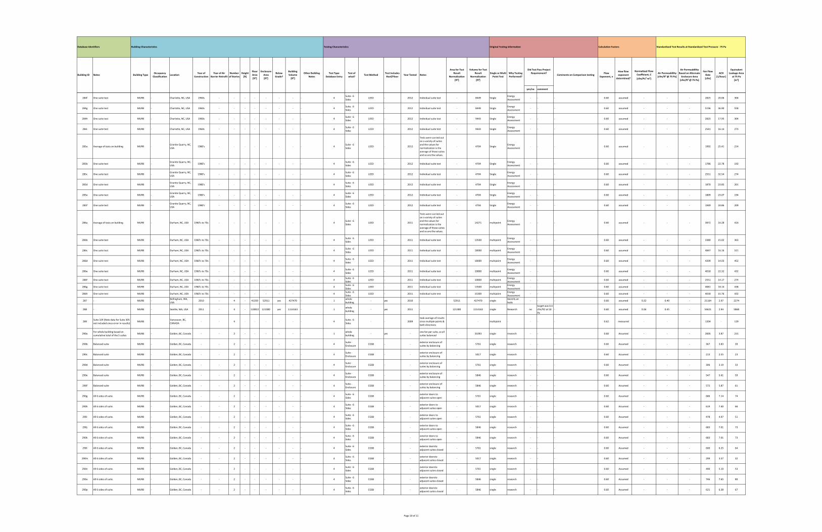
yes/no comment
How flow
exponent
determined?
Normalized Flow
Coefficient, C
[cfm/Pan∙m²]
Air Permeablility
[cfm/ft² @ 75 Pa]
Equivalent
Leakage Area
at 75 Pa
[in²]
Calculation FactorsOriginal Testing informationTesting Characteristics
Test Includes
Roof/FloorYear Tested Notes
Building CharacteristicsDatabase Identifiers
Building ID Notes Building TypeOccupancy
ClassificationLocation
Year of
Construction
Year of Air
Barrier Retrofit
Number
of Stories
Height
[ft]
Floor
Area
[ft²]
Enclosure
Area
[ft²]
Below
Grade?
Building
Volume
[ft³]
Other Building
Notes
Test Type
Database Entry
Test of
what?Test Method
Standardized Test Results at Standardized Test Pressure ‐ 75 Pa
Area for Test
Result
Normalization
[ft²]
Volume for Test
Result
Normalization
[ft³]
Comments on Comparison testingWhy Testing
Performed?
Single or Multi
Point Test
Flow
Exponent, n
Did Test Pass Project
Requirement?
Air Permeablility
Based on Alternate
Enclosure Area
[cfm/ft² @ 75 Pa]
Fan Flow
Rate
[cfm]
ACH
[1/hour]
284f One suite test MURB ‐ Charlotte, NC, USA 1960s ‐ ‐ ‐ ‐ ‐ ‐ ‐ ‐ 4Suite ‐ 6
SidesLEED ‐ 2012 Individual suite test ‐ 8449 Single
Energy
Assessment‐ ‐ ‐ 0.60 assumed ‐ ‐ ‐ 2825 20.06 304
284g One suite test MURB ‐ Charlotte, NC, USA 1960s ‐ ‐ ‐ ‐ ‐ ‐ ‐ ‐ 4Suite ‐ 6
SidesLEED ‐ 2012 Individual suite test ‐ 8449 Single
Energy
Assessment‐ ‐ ‐ 0.60 assumed ‐ ‐ ‐ 5196 36.90 558
284h One suite test MURB ‐ Charlotte, NC, USA 1960s ‐ ‐ ‐ ‐ ‐ ‐ ‐ ‐ 4Suite ‐ 6
SidesLEED ‐ 2012 Individual suite test ‐ 9443 Single
Energy
Assessment‐ ‐ ‐ 0.60 assumed ‐ ‐ ‐ 2825 17.95 304
284i One suite test MURB ‐ Charlotte, NC, USA 1960s ‐ ‐ ‐ ‐ ‐ ‐ ‐ ‐ 4Suite ‐ 6
SidesLEED ‐ 2012 Individual suite test ‐ 9443 Single
Energy
Assessment‐ ‐ ‐ 0.60 assumed ‐ ‐ ‐ 2541 16.14 273
285a Average of tests on building MURB ‐Granite Quarry, NC,
USA1980's ‐ ‐ ‐ ‐ ‐ ‐ ‐ ‐ 4
Suite ‐ 6
SidesLEED ‐ 2012
Tests were carried out
on a variety of suites
and the values for
normalization is the
average of those suites
and so are the values.
‐ 4704 SingleEnergy
Assessment‐ ‐ ‐ 0.60 assumed ‐ ‐ ‐ 1992 25.41 214
285b One suite test MURB ‐Granite Quarry, NC,
USA1980's ‐ ‐ ‐ ‐ ‐ ‐ ‐ ‐ 4
Suite ‐ 6
SidesLEED ‐ 2012 Individual suite test ‐ 4704 Single
Energy
Assessment‐ ‐ ‐ 0.60 assumed ‐ ‐ ‐ 1786 22.78 192
285c One suite test MURB ‐Granite Quarry, NC,
USA1980's ‐ ‐ ‐ ‐ ‐ ‐ ‐ ‐ 4
Suite ‐ 6
SidesLEED ‐ 2012 Individual suite test ‐ 4704 Single
Energy
Assessment‐ ‐ ‐ 0.60 assumed ‐ ‐ ‐ 2551 32.54 274
285d One suite test MURB ‐Granite Quarry, NC,
USA1980's ‐ ‐ ‐ ‐ ‐ ‐ ‐ ‐ 4
Suite ‐ 6
SidesLEED ‐ 2012 Individual suite test ‐ 4704 Single
Energy
Assessment‐ ‐ ‐ 0.60 assumed ‐ ‐ ‐ 1870 23.85 201
285e One suite test MURB ‐Granite Quarry, NC,
USA1980's ‐ ‐ ‐ ‐ ‐ ‐ ‐ ‐ 4
Suite ‐ 6
SidesLEED ‐ 2012 Individual suite test ‐ 4704 Single
Energy
Assessment‐ ‐ ‐ 0.60 assumed ‐ ‐ ‐ 1809 23.07 194
285f One suite test MURB ‐Granite Quarry, NC,
USA1980's ‐ ‐ ‐ ‐ ‐ ‐ ‐ ‐ 4
Suite ‐ 6
SidesLEED ‐ 2012 Individual suite test ‐ 4704 Single
Energy
Assessment‐ ‐ ‐ 0.60 assumed ‐ ‐ ‐ 1949 24.86 209
286a Average of tests on building MURB ‐ Durham, NC, USA 1960's to 70s ‐ ‐ ‐ ‐ ‐ ‐ ‐ ‐ 4Suite ‐ 6
SidesLEED ‐ 2011
Tests were carried out
on a variety of suites
and the values for
normalization is the
average of those suites
and so are the values.
‐ 14271 multipointEnergy
Assessment‐ ‐ ‐ 0.60 assumed ‐ ‐ ‐ 3872 16.28 416
286b One suite test MURB ‐ Durham, NC, USA 1960's to 70s ‐ ‐ ‐ ‐ ‐ ‐ ‐ ‐ 4Suite ‐ 6
SidesLEED ‐ 2011 Individual suite test ‐ 13500 multipoint
Energy
Assessment‐ ‐ ‐ 0.60 assumed ‐ ‐ ‐ 3380 15.02 363
286c One suite test MURB ‐ Durham, NC, USA 1960's to 70s ‐ ‐ ‐ ‐ ‐ ‐ ‐ ‐ 4Suite ‐ 6
SidesLEED ‐ 2011 Individual suite test ‐ 18000 multipoint
Energy
Assessment‐ ‐ ‐ 0.60 assumed ‐ ‐ ‐ 4847 16.16 521
286d One suite test MURB ‐ Durham, NC, USA 1960's to 70s ‐ ‐ ‐ ‐ ‐ ‐ ‐ ‐ 4Suite ‐ 6
SidesLEED ‐ 2011 Individual suite test ‐ 18000 multipoint
Energy
Assessment‐ ‐ ‐ 0.60 assumed ‐ ‐ ‐ 4209 14.03 452
286e One suite test MURB ‐ Durham, NC, USA 1960's to 70s ‐ ‐ ‐ ‐ ‐ ‐ ‐ ‐ 4Suite ‐ 6
SidesLEED ‐ 2011 Individual suite test ‐ 10800 multipoint
Energy
Assessment‐ ‐ ‐ 0.60 assumed ‐ ‐ ‐ 4018 22.32 432
286f One suite test MURB ‐ Durham, NC, USA 1960's to 70s ‐ ‐ ‐ ‐ ‐ ‐ ‐ ‐ 4Suite ‐ 6
SidesLEED ‐ 2011 Individual suite test ‐ 10800 multipoint
Energy
Assessment‐ ‐ ‐ 0.60 assumed ‐ ‐ ‐ 2551 14.17 274
286g One suite test MURB ‐ Durham, NC, USA 1960's to 70s ‐ ‐ ‐ ‐ ‐ ‐ ‐ ‐ 4Suite ‐ 6
SidesLEED ‐ 2011 Individual suite test ‐ 13500 multipoint
Energy
Assessment‐ ‐ ‐ 0.60 assumed ‐ ‐ ‐ 4081 18.14 438
286h One suite test MURB ‐ Durham, NC, USA 1960's to 70s ‐ ‐ ‐ ‐ ‐ ‐ ‐ ‐ 4Suite ‐ 6
SidesLEED ‐ 2011 Individual suite test ‐ 15300 multipoint
Energy
Assessment‐ ‐ ‐ 0.60 assumed ‐ ‐ ‐ 4018 15.76 432
287 ‐ MURB ‐Bellingham, WA,
USA2010 ‐ 4 ‐ 41359 52911 yes 427470 ‐ 1
whole
building‐ yes 2010 ‐ 52911 427470 single
Identify air
leaks‐ ‐ ‐ 0.60 assumed 0.32 0.40 ‐ 21164 2.97 2274
288 ‐ MURB ‐ Seattle, WA, USA 2011 ‐ 4 ‐ 110822 121380 yes 1114163 ‐ 1whole
building‐ yes 2011 ‐ 121380 1114163 single Research no
target was 0.4
cfm/ft2 at 50
Pa
‐ 0.60 assumed 0.36 0.45 ‐ 54621 2.94 5868
289Suite 104 (Note data for Suite 305
not included since error in results)MURB ‐
Vancouver, BC,
CANADA‐ ‐ 4 ‐ ‐ ‐ ‐ ‐ ‐ 4
Suite ‐ 6
Sides‐ ‐ 2009
took average of results
since multiple points &
both directions
‐ ‐ multipoint ‐ ‐ ‐ ‐ 0.62 measured ‐ ‐ ‐ 1204 ‐ 129
290aFor whole building based on
cumulative total of the 5 suitesMURB ‐ Golden, BC, Canada ‐ ‐ 2 ‐ ‐ ‐ ‐ ‐ ‐ 1
whole
building‐ yes ‐
one fan per suite, so all
suites balanced‐ 31093 single research ‐ ‐ ‐ 0.60 Assumed ‐ ‐ ‐ 2005 3.87 215
290b Balanced suite MURB ‐ Golden, BC, Canada ‐ ‐ 2 ‐ ‐ ‐ ‐ ‐ ‐ 4Suite ‐
EnclosureCGSB ‐ ‐
exterior enclosure of
suites by balancing‐ 5761 single research ‐ ‐ ‐ 0.60 Assumed ‐ ‐ ‐ 367 3.83 39
290c Balanced suite MURB ‐ Golden, BC, Canada ‐ ‐ 2 ‐ ‐ ‐ ‐ ‐ ‐ 4Suite ‐
EnclosureCGSB ‐ ‐
exterior enclosure of
suites by balancing‐ 5017 single research ‐ ‐ ‐ 0.60 Assumed ‐ ‐ ‐ 213 2.55 23
290d Balanced suite MURB ‐ Golden, BC, Canada ‐ ‐ 2 ‐ ‐ ‐ ‐ ‐ ‐ 4Suite ‐
EnclosureCGSB ‐ ‐
exterior enclosure of
suites by balancing‐ 5761 single research ‐ ‐ ‐ 0.60 Assumed ‐ ‐ ‐ 306 3.19 33
290e Balanced suite MURB ‐ Golden, BC, Canada ‐ ‐ 2 ‐ ‐ ‐ ‐ ‐ ‐ 4Suite ‐
EnclosureCGSB ‐ ‐
exterior enclosure of
suites by balancing‐ 5846 single research ‐ ‐ ‐ 0.60 Assumed ‐ ‐ ‐ 547 5.61 59
290f Balanced suite MURB ‐ Golden, BC, Canada ‐ ‐ 2 ‐ ‐ ‐ ‐ ‐ ‐ 4Suite ‐
EnclosureCGSB ‐ ‐
exterior enclosure of
suites by balancing‐ 5846 single research ‐ ‐ ‐ 0.60 Assumed ‐ ‐ ‐ 572 5.87 61
290g All 6 sides of suite. MURB ‐ Golden, BC, Canada ‐ ‐ 2 ‐ ‐ ‐ ‐ ‐ ‐ 4Suite ‐ 6
SidesCGSB ‐ ‐
exterior doors to
adjacent suites open‐ 5761 single research ‐ ‐ ‐ 0.60 Assumed ‐ ‐ ‐ 686 7.14 74
290h All 6 sides of suite. MURB ‐ Golden, BC, Canada ‐ ‐ 2 ‐ ‐ ‐ ‐ ‐ ‐ 4Suite ‐ 6
SidesCGSB ‐ ‐
exterior doors to
adjacent suites open‐ 5017 single research ‐ ‐ ‐ 0.60 Assumed ‐ ‐ ‐ 619 7.40 66
290i All 6 sides of suite. MURB ‐ Golden, BC, Canada ‐ ‐ 2 ‐ ‐ ‐ ‐ ‐ ‐ 4Suite ‐ 6
SidesCGSB ‐ ‐
exterior doors to
adjacent suites open‐ 5761 single research ‐ ‐ ‐ 0.60 Assumed ‐ ‐ ‐ 478 4.97 51
290j All 6 sides of suite. MURB ‐ Golden, BC, Canada ‐ ‐ 2 ‐ ‐ ‐ ‐ ‐ ‐ 4Suite ‐ 6
SidesCGSB ‐ ‐
exterior doors to
adjacent suites open‐ 5846 single research ‐ ‐ ‐ 0.60 Assumed ‐ ‐ ‐ 683 7.01 73
290k All 6 sides of suite. MURB ‐ Golden, BC, Canada ‐ ‐ 2 ‐ ‐ ‐ ‐ ‐ ‐ 4Suite ‐ 6
SidesCGSB ‐ ‐
exterior doors to
adjacent suites open‐ 5846 single research ‐ ‐ ‐ 0.60 Assumed ‐ ‐ ‐ 683 7.01 73
290l All 6 sides of suite. MURB ‐ Golden, BC, Canada ‐ ‐ 2 ‐ ‐ ‐ ‐ ‐ ‐ 4Suite ‐ 6
SidesCGSB ‐ ‐
exterior doorsto
adjacent suites closed‐ 5761 single research ‐ ‐ ‐ 0.60 Assumed ‐ ‐ ‐ 600 6.25 64
290m All 6 sides of suite. MURB ‐ Golden, BC, Canada ‐ ‐ 2 ‐ ‐ ‐ ‐ ‐ ‐ 4Suite ‐ 6
SidesCGSB ‐ ‐
exterior doorsto
adjacent suites closed‐ 5017 single research ‐ ‐ ‐ 0.60 Assumed ‐ ‐ ‐ 299 3.57 32
290n All 6 sides of suite. MURB ‐ Golden, BC, Canada ‐ ‐ 2 ‐ ‐ ‐ ‐ ‐ ‐ 4Suite ‐ 6
SidesCGSB ‐ ‐
exterior doorsto
adjacent suites closed‐ 5761 single research ‐ ‐ ‐ 0.60 Assumed ‐ ‐ ‐ 490 5.10 53
290o All 6 sides of suite. MURB ‐ Golden, BC, Canada ‐ ‐ 2 ‐ ‐ ‐ ‐ ‐ ‐ 4Suite ‐ 6
SidesCGSB ‐ ‐
exterior doorsto
adjacent suites closed‐ 5846 single research ‐ ‐ ‐ 0.60 Assumed ‐ ‐ ‐ 746 7.65 80
290p All 6 sides of suite. MURB ‐ Golden, BC, Canada ‐ ‐ 2 ‐ ‐ ‐ ‐ ‐ ‐ 4Suite ‐ 6
SidesCGSB ‐ ‐
exterior doorsto
adjacent suites closed‐ 5846 single research ‐ ‐ ‐ 0.60 Assumed ‐ ‐ ‐ 621 6.38 67
Page 10 of 11
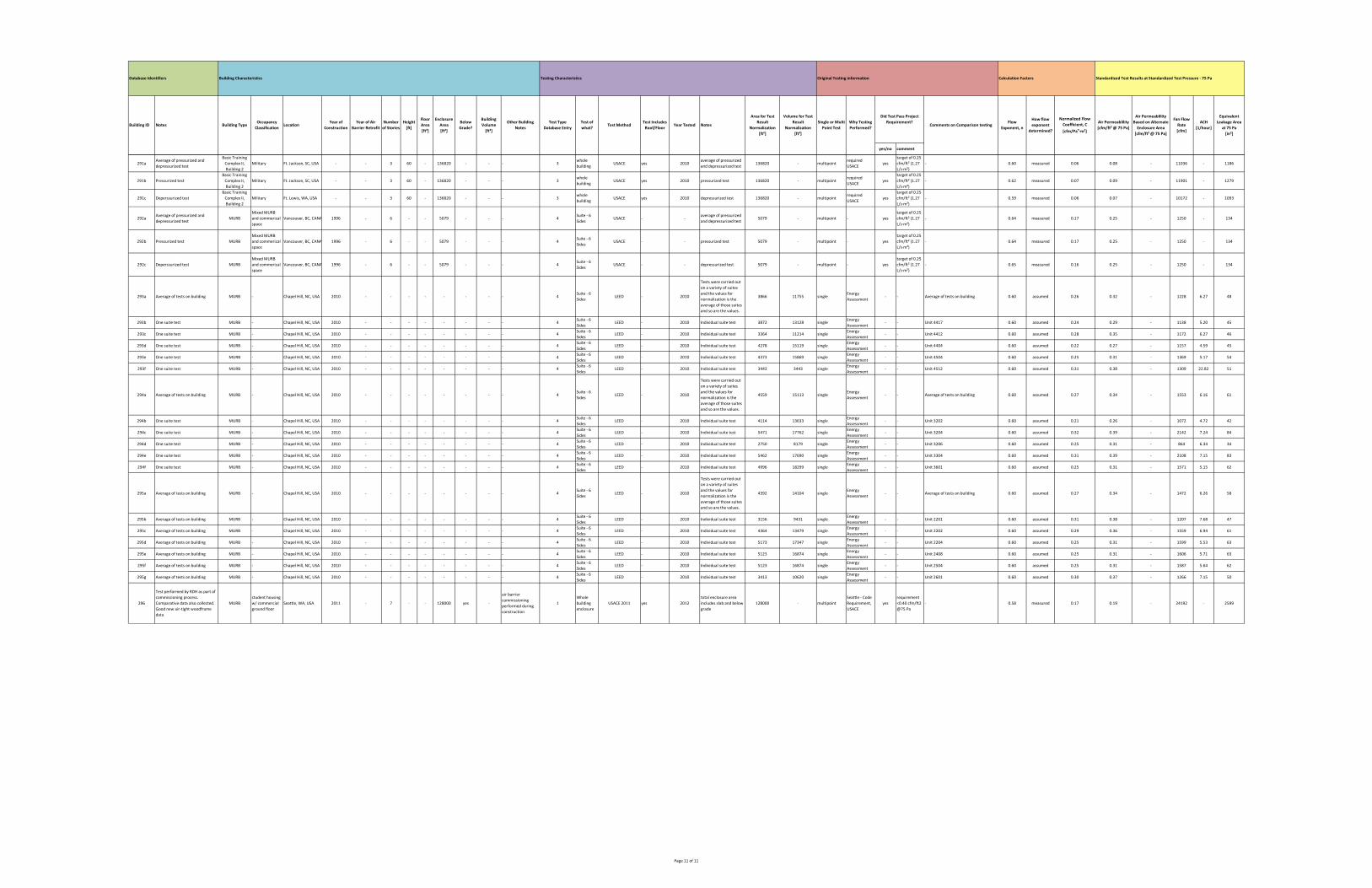
yes/no comment
How flow
exponent
determined?
Normalized Flow
Coefficient, C
[cfm/Pan∙m²]
Air Permeablility
[cfm/ft² @ 75 Pa]
Equivalent
Leakage Area
at 75 Pa
[in²]
Calculation FactorsOriginal Testing informationTesting Characteristics
Test Includes
Roof/FloorYear Tested Notes
Building CharacteristicsDatabase Identifiers
Building ID Notes Building TypeOccupancy
ClassificationLocation
Year of
Construction
Year of Air
Barrier Retrofit
Number
of Stories
Height
[ft]
Floor
Area
[ft²]
Enclosure
Area
[ft²]
Below
Grade?
Building
Volume
[ft³]
Other Building
Notes
Test Type
Database Entry
Test of
what?Test Method
Standardized Test Results at Standardized Test Pressure ‐ 75 Pa
Area for Test
Result
Normalization
[ft²]
Volume for Test
Result
Normalization
[ft³]
Comments on Comparison testingWhy Testing
Performed?
Single or Multi
Point Test
Flow
Exponent, n
Did Test Pass Project
Requirement?
Air Permeablility
Based on Alternate
Enclosure Area
[cfm/ft² @ 75 Pa]
Fan Flow
Rate
[cfm]
ACH
[1/hour]
291aAverage of pressurized and
depressurized test
Basic Training
Complex II,
Building 2
Military Ft. Jackson, SC, USA ‐ ‐ 3 60 ‐ 136820 ‐ ‐ ‐ 3whole
buildingUSACE yes 2010
average of pressurized
and depressurized test136820 ‐ multipoint
required
USACEyes
target of 0.25
cfm/ft² (1.27
L/s∙m²)
‐ 0.60 measured 0.06 0.08 ‐ 11036 ‐ 1186
291b Pressurized test
Basic Training
Complex II,
Building 2
Military Ft. Jackson, SC, USA ‐ ‐ 3 60 ‐ 136820 ‐ ‐ ‐ 3whole
buildingUSACE yes 2010 pressurized test 136820 ‐ multipoint
required
USACEyes
target of 0.25
cfm/ft² (1.27
L/s∙m²)
‐ 0.62 measured 0.07 0.09 ‐ 11901 ‐ 1279
291c Deperssurized test
Basic Training
Complex II,
Building 2
Military Ft. Lewis, WA, USA ‐ ‐ 3 60 ‐ 136820 ‐ ‐ ‐ 3whole
buildingUSACE yes 2010 depressurized test 136820 ‐ multipoint
required
USACEyes
target of 0.25
cfm/ft² (1.27
L/s∙m²)
‐ 0.59 measured 0.06 0.07 ‐ 10172 ‐ 1093
292aAverage of pressurized and
depressurized testMURB
Mixed MURB
and commerical
space
Vancouver, BC, CANA 1996 ‐ 6 ‐ ‐ 5079 ‐ ‐ ‐ 4Suite ‐ 6
SidesUSACE ‐ ‐
average of pressurized
and depressurized test5079 ‐ multipoint ‐ yes
target of 0.25
cfm/ft² (1.27
L/s∙m²)
‐ 0.64 measured 0.17 0.25 ‐ 1250 ‐ 134
292b Pressurized test MURB
Mixed MURB
and commerical
space
Vancouver, BC, CANA 1996 ‐ 6 ‐ ‐ 5079 ‐ ‐ ‐ 4Suite ‐ 6
SidesUSACE ‐ ‐ pressurized test 5079 ‐ multipoint ‐ yes
target of 0.25
cfm/ft² (1.27
L/s∙m²)
‐ 0.64 measured 0.17 0.25 ‐ 1250 ‐ 134
292c Deperssurized test MURB
Mixed MURB
and commerical
space
Vancouver, BC, CANA 1996 ‐ 6 ‐ ‐ 5079 ‐ ‐ ‐ 4Suite ‐ 6
SidesUSACE ‐ ‐ depressurized test 5079 ‐ multipoint ‐ yes
target of 0.25
cfm/ft² (1.27
L/s∙m²)
‐ 0.65 measured 0.16 0.25 ‐ 1250 ‐ 134
293a Average of tests on building MURB ‐ Chapel Hill, NC, USA 2010 ‐ ‐ ‐ ‐ ‐ ‐ ‐ ‐ 4Suite ‐ 6
SidesLEED ‐ 2010
Tests were carried out
on a variety of suites
and the values for
normalization is the
average of those suites
and so are the values.
3866 11755 singleEnergy
Assessment‐ ‐ Average of tests on building 0.60 assumed 0.26 0.32 ‐ 1228 6.27 48
293b One suite test MURB ‐ Chapel Hill, NC, USA 2010 ‐ ‐ ‐ ‐ ‐ ‐ ‐ ‐ 4Suite ‐ 6
SidesLEED ‐ 2010 Individual suite test 3872 13128 single
Energy
Assessment‐ ‐ Unit 4417 0.60 assumed 0.24 0.29 ‐ 1138 5.20 45
293c One suite test MURB ‐ Chapel Hill, NC, USA 2010 ‐ ‐ ‐ ‐ ‐ ‐ ‐ ‐ 4Suite ‐ 6
SidesLEED ‐ 2010 Individual suite test 3364 11214 single
Energy
Assessment‐ ‐ Unit 4412 0.60 assumed 0.28 0.35 ‐ 1172 6.27 46
293d One suite test MURB ‐ Chapel Hill, NC, USA 2010 ‐ ‐ ‐ ‐ ‐ ‐ ‐ ‐ 4Suite ‐ 6
SidesLEED ‐ 2010 Individual suite test 4278 15119 single
Energy
Assessment‐ ‐ Unit 4404 0.60 assumed 0.22 0.27 ‐ 1157 4.59 45
293e One suite test MURB ‐ Chapel Hill, NC, USA 2010 ‐ ‐ ‐ ‐ ‐ ‐ ‐ ‐ 4Suite ‐ 6
SidesLEED ‐ 2010 Individual suite test 4373 15869 single
Energy
Assessment‐ ‐ Unit 4504 0.60 assumed 0.25 0.31 ‐ 1369 5.17 54
293f One suite test MURB ‐ Chapel Hill, NC, USA 2010 ‐ ‐ ‐ ‐ ‐ ‐ ‐ ‐ 4Suite ‐ 6
SidesLEED ‐ 2010 Individual suite test 3443 3443 single
Energy
Assessment‐ ‐ Unit 4512 0.60 assumed 0.31 0.38 ‐ 1309 22.82 51
294a Average of tests on building MURB ‐ Chapel Hill, NC, USA 2010 ‐ ‐ ‐ ‐ ‐ ‐ ‐ ‐ 4Suite ‐ 6
SidesLEED ‐ 2010
Tests were carried out
on a variety of suites
and the values for
normalization is the
average of those suites
and so are the values.
4559 15113 singleEnergy
Assessment‐ ‐ Average of tests on building 0.60 assumed 0.27 0.34 ‐ 1553 6.16 61
294b One suite test MURB ‐ Chapel Hill, NC, USA 2010 ‐ ‐ ‐ ‐ ‐ ‐ ‐ ‐ 4Suite ‐ 6
SidesLEED ‐ 2010 Individual suite test 4114 13633 single
Energy
Assessment‐ ‐ Unit 3202 0.60 assumed 0.21 0.26 ‐ 1072 4.72 42
294c One suite test MURB ‐ Chapel Hill, NC, USA 2010 ‐ ‐ ‐ ‐ ‐ ‐ ‐ ‐ 4Suite ‐ 6
SidesLEED ‐ 2010 Individual suite test 5471 17762 single
Energy
Assessment‐ ‐ Unit 3204 0.60 assumed 0.32 0.39 ‐ 2142 7.24 84
294d One suite test MURB ‐ Chapel Hill, NC, USA 2010 ‐ ‐ ‐ ‐ ‐ ‐ ‐ ‐ 4Suite ‐ 6
SidesLEED ‐ 2010 Individual suite test 2750 8179 single
Energy
Assessment‐ ‐ Unit 3206 0.60 assumed 0.25 0.31 ‐ 864 6.34 34
294e One suite test MURB ‐ Chapel Hill, NC, USA 2010 ‐ ‐ ‐ ‐ ‐ ‐ ‐ ‐ 4Suite ‐ 6
SidesLEED ‐ 2010 Individual suite test 5462 17690 single
Energy
Assessment‐ ‐ Unit 3304 0.60 assumed 0.31 0.39 ‐ 2108 7.15 83
294f One suite test MURB ‐ Chapel Hill, NC, USA 2010 ‐ ‐ ‐ ‐ ‐ ‐ ‐ ‐ 4Suite ‐ 6
SidesLEED ‐ 2010 Individual suite test 4996 18299 single
Energy
Assessment‐ ‐ Unit 3601 0.60 assumed 0.25 0.31 ‐ 1571 5.15 62
295a Average of tests on building MURB ‐ Chapel Hill, NC, USA 2010 ‐ ‐ ‐ ‐ ‐ ‐ ‐ ‐ 4Suite ‐ 6
SidesLEED ‐ 2010
Tests were carried out
on a variety of suites
and the values for
normalization is the
average of those suites
and so are the values.
4392 14104 singleEnergy
Assessment‐ ‐ Average of tests on building 0.60 assumed 0.27 0.34 ‐ 1472 6.26 58
295b Average of tests on building MURB ‐ Chapel Hill, NC, USA 2010 ‐ ‐ ‐ ‐ ‐ ‐ ‐ ‐ 4Suite ‐ 6
SidesLEED ‐ 2010 Individual suite test 3156 9431 single
Energy
Assessment‐ ‐ Unit 2201 0.60 assumed 0.31 0.38 ‐ 1207 7.68 47
295c Average of tests on building MURB ‐ Chapel Hill, NC, USA 2010 ‐ ‐ ‐ ‐ ‐ ‐ ‐ ‐ 4Suite ‐ 6
SidesLEED ‐ 2010 Individual suite test 4364 13479 single
Energy
Assessment‐ ‐ Unit 2202 0.60 assumed 0.29 0.36 ‐ 1559 6.94 61
295d Average of tests on building MURB ‐ Chapel Hill, NC, USA 2010 ‐ ‐ ‐ ‐ ‐ ‐ ‐ ‐ 4Suite ‐ 6
SidesLEED ‐ 2010 Individual suite test 5173 17347 single
Energy
Assessment‐ ‐ Unit 2204 0.60 assumed 0.25 0.31 ‐ 1599 5.53 63
295e Average of tests on building MURB ‐ Chapel Hill, NC, USA 2010 ‐ ‐ ‐ ‐ ‐ ‐ ‐ ‐ 4Suite ‐ 6
SidesLEED ‐ 2010 Individual suite test 5123 16874 single
Energy
Assessment‐ ‐ Unit 2408 0.60 assumed 0.25 0.31 ‐ 1606 5.71 63
295f Average of tests on building MURB ‐ Chapel Hill, NC, USA 2010 ‐ ‐ ‐ ‐ ‐ ‐ ‐ ‐ 4Suite ‐ 6
SidesLEED ‐ 2010 Individual suite test 5123 16874 single
Energy
Assessment‐ ‐ Unit 2504 0.60 assumed 0.25 0.31 ‐ 1587 5.64 62
295g Average of tests on building MURB ‐ Chapel Hill, NC, USA 2010 ‐ ‐ ‐ ‐ ‐ ‐ ‐ ‐ 4Suite ‐ 6
SidesLEED ‐ 2010 Individual suite test 3413 10620 single
Energy
Assessment‐ ‐ Unit 2601 0.60 assumed 0.30 0.37 ‐ 1266 7.15 50
296
Test performed by RDH as part of
commissioning process.
Comparative data also collected.
Good new air‐tight woodframe
data
MURB
student housing
w/ commercial
ground floor
Seattle, WA, USA 2011 ‐ 7 ‐ ‐ 128000 yes ‐
air barrier
commissioning
performed during
construction
1
Whole
building
enclosure
USACE 2011 yes 2012
total enclosure area
includes slab and below
grade
128000 ‐ multipoint
Seattle ‐ Code
Requirement,
USACE
yes
requirement
<0.40 cfm/ft2
@75 Pa
‐ 0.58 measured 0.17 0.19 ‐ 24192 ‐ 2599
Page 11 of 11

Appendix B
Industry Su
rvey
Page 1
MURB Air-Tightness Industry SurveyMURB Air-Tightness Industry SurveyMURB Air-Tightness Industry SurveyMURB Air-Tightness Industry Survey
RDH Building Engineering Ltd. (RDH) is undertaking a research study into the Air Leakage Control of MultiUnit Residential Buildings (MURBs) on behalf of Canada Mortgage and Housing Corporation (CMHC) and would like to get your feedback via an online survey to gauge the current level of work being performed in the control of air leakage within large buildings as part of this research study. The intent of this survey is to determine which testing methods and current procedures, codes, and standards related to airleakage testing for large buildings are being used by practitioners, which are most effective, and whether whole building air tightness testing is warranted for large buildings including MURBs. This survey is being distributed to building professionals in most jurisdictions throughout North America. The results of this survey will be published later in 2012.
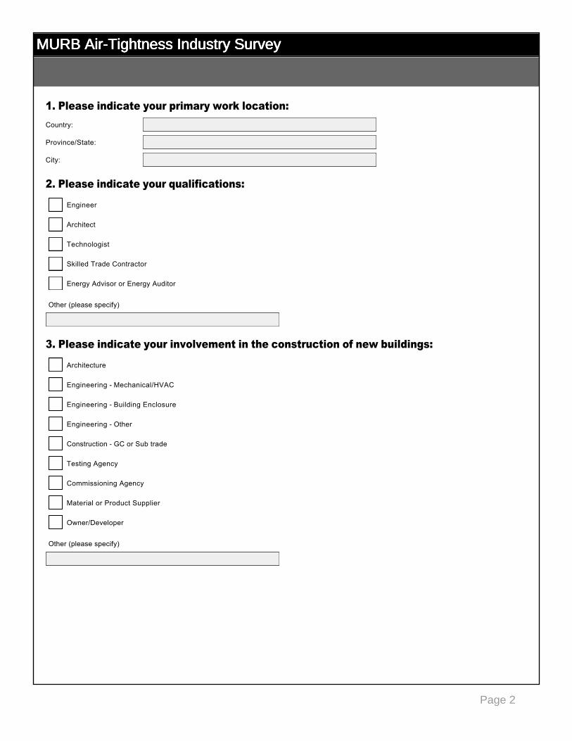
Page 2
MURB Air-Tightness Industry SurveyMURB Air-Tightness Industry SurveyMURB Air-Tightness Industry SurveyMURB Air-Tightness Industry Survey
1. Please indicate your primary work location:
2. Please indicate your qualifications:
3. Please indicate your involvement in the construction of new buildings:
Country:
Province/State:
City:
Engineer
gfedc
Architect
gfedc
Technologist
gfedc
Skilled Trade Contractor
gfedc
Energy Advisor or Energy Auditor
gfedc
Other (please specify)
Architecture
gfedc
Engineering Mechanical/HVAC
gfedc
Engineering Building Enclosure
gfedc
Engineering Other
gfedc
Construction GC or Sub trade
gfedc
Testing Agency
gfedc
Commissioning Agency
gfedc
Material or Product Supplier
gfedc
Owner/Developer
gfedc
Other (please specify)
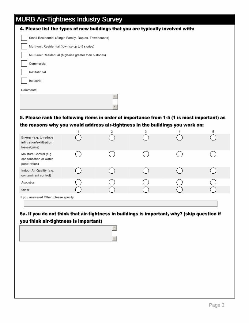
Page 3
MURB Air-Tightness Industry SurveyMURB Air-Tightness Industry SurveyMURB Air-Tightness Industry SurveyMURB Air-Tightness Industry Survey4. Please list the types of new buildings that you are typically involved with:
5. Please rank the following items in order of importance from 15 (1 is most important) as the reasons why you would address airtightness in the buildings you work on:
5a. If you do not think that airtightness in buildings is important, why? (skip question if you think airtightness is important)
1 2 3 4 5
Energy (e.g. to reduce infiltration/exfiltration losses/gains)
nmlkj nmlkj nmlkj nmlkj nmlkj
Moisture Control (e.g. condensation or water penetration)
nmlkj nmlkj nmlkj nmlkj nmlkj
Indoor Air Quality (e.g. contaminant control)
nmlkj nmlkj nmlkj nmlkj nmlkj
Acoustics nmlkj nmlkj nmlkj nmlkj nmlkj
Other nmlkj nmlkj nmlkj nmlkj nmlkj
55
66
Small Residential (Single Family, Duplex, Townhouses)
gfedc
Multiunit Residential (lowrise up to 5 stories)
gfedc
Multiunit Residential (highrise greater than 5 stories)
gfedc
Commercial
gfedc
Institutional
gfedc
Industrial
gfedc
Comments:
55
66
If you answered Other, please specify:
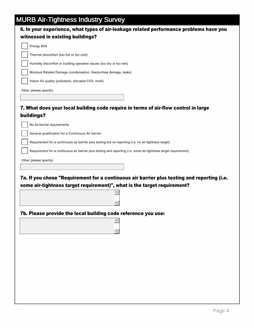
Page 4
MURB Air-Tightness Industry SurveyMURB Air-Tightness Industry SurveyMURB Air-Tightness Industry SurveyMURB Air-Tightness Industry Survey6. In your experience, what types of airleakage related performance problems have you witnessed in existing buildings?
7. What does your local building code require in terms of airflow control in large buildings?
7a. If you chose "Requirement for a continuous air barrier plus testing and reporting (i.e. some airtightness target requirement)", what is the target requirement?
7b. Please provide the local building code reference you use:
55
66
55
66
Energy Bills
gfedc
Thermal discomfort (too hot or too cold)
gfedc
Humidity discomfort or building operation issues (too dry or too wet)
gfedc
Moisture Related Damage (condensation, freezethaw damage, leaks)
gfedc
Indoor Air quality (pollutants, elevated CO2, mold)
gfedc
Other (please specify)
No Airbarrier requirements
gfedc
General qualification for a Continuous Air barrier
gfedc
Requirement for a continuous air barrier plus testing but no reporting (i.e. no airtightness target)
gfedc
Requirement for a continuous air barrier plus testing and reporting (i.e. some airtightness target requirement)
gfedc
Other (please specify)
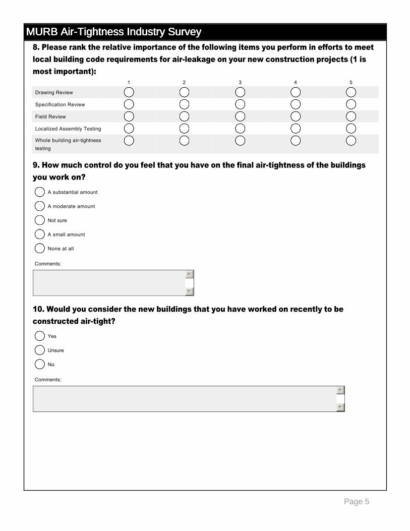
Page 5
MURB Air-Tightness Industry SurveyMURB Air-Tightness Industry SurveyMURB Air-Tightness Industry SurveyMURB Air-Tightness Industry Survey8. Please rank the relative importance of the following items you perform in efforts to meet local building code requirements for airleakage on your new construction projects (1 is most important):
9. How much control do you feel that you have on the final airtightness of the buildings you work on?
10. Would you consider the new buildings that you have worked on recently to be constructed airtight?
1 2 3 4 5
Drawing Review nmlkj nmlkj nmlkj nmlkj nmlkj
Specification Review nmlkj nmlkj nmlkj nmlkj nmlkj
Field Review nmlkj nmlkj nmlkj nmlkj nmlkj
Localized Assembly Testing nmlkj nmlkj nmlkj nmlkj nmlkj
Whole building airtightness testing
nmlkj nmlkj nmlkj nmlkj nmlkj
A substantial amount
nmlkj
A moderate amount
nmlkj
Not sure
nmlkj
A small amount
nmlkj
None at all
nmlkj
Comments:
55
66
Yes
nmlkj
Unsure
nmlkj
No
nmlkj
Comments:
55
66
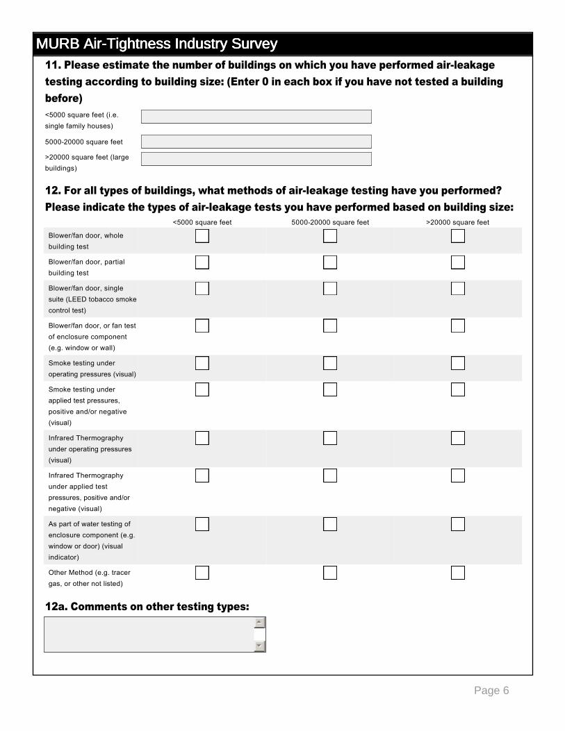
Page 6
MURB Air-Tightness Industry SurveyMURB Air-Tightness Industry SurveyMURB Air-Tightness Industry SurveyMURB Air-Tightness Industry Survey11. Please estimate the number of buildings on which you have performed airleakage testing according to building size: (Enter 0 in each box if you have not tested a building before)
12. For all types of buildings, what methods of airleakage testing have you performed? Please indicate the types of airleakage tests you have performed based on building size:
12a. Comments on other testing types:
<5000 square feet (i.e. single family houses)
500020000 square feet
>20000 square feet (large buildings)
<5000 square feet 500020000 square feet >20000 square feet
Blower/fan door, whole building test
gfedc gfedc gfedc
Blower/fan door, partial building test
gfedc gfedc gfedc
Blower/fan door, single suite (LEED tobacco smoke control test)
gfedc gfedc gfedc
Blower/fan door, or fan test of enclosure component (e.g. window or wall)
gfedc gfedc gfedc
Smoke testing under operating pressures (visual)
gfedc gfedc gfedc
Smoke testing under applied test pressures, positive and/or negative (visual)
gfedc gfedc gfedc
Infrared Thermography under operating pressures (visual)
gfedc gfedc gfedc
Infrared Thermography under applied test pressures, positive and/or negative (visual)
gfedc gfedc gfedc
As part of water testing of enclosure component (e.g. window or door) (visual indicator)
gfedc gfedc gfedc
Other Method (e.g. tracer gas, or other not listed)
gfedc gfedc gfedc
55
66
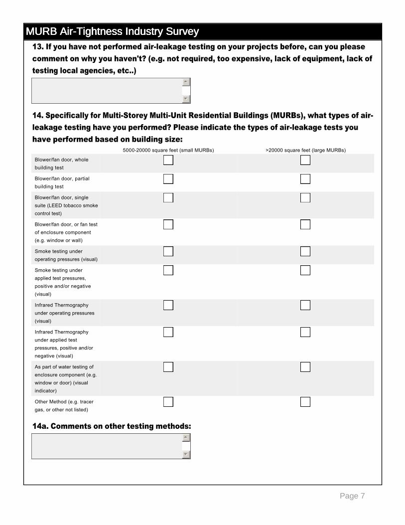
Page 7
MURB Air-Tightness Industry SurveyMURB Air-Tightness Industry SurveyMURB Air-Tightness Industry SurveyMURB Air-Tightness Industry Survey13. If you have not performed airleakage testing on your projects before, can you please comment on why you haven't? (e.g. not required, too expensive, lack of equipment, lack of testing local agencies, etc..)
14. Specifically for MultiStorey MultiUnit Residential Buildings (MURBs), what types of airleakage testing have you performed? Please indicate the types of airleakage tests you have performed based on building size:
14a. Comments on other testing methods:
55
66
500020000 square feet (small MURBs) >20000 square feet (large MURBs)
Blower/fan door, whole building test
gfedc gfedc
Blower/fan door, partial building test
gfedc gfedc
Blower/fan door, single suite (LEED tobacco smoke control test)
gfedc gfedc
Blower/fan door, or fan test of enclosure component (e.g. window or wall)
gfedc gfedc
Smoke testing under operating pressures (visual)
gfedc gfedc
Smoke testing under applied test pressures, positive and/or negative (visual)
gfedc gfedc
Infrared Thermography under operating pressures (visual)
gfedc gfedc
Infrared Thermography under applied test pressures, positive and/or negative (visual)
gfedc gfedc
As part of water testing of enclosure component (e.g. window or door) (visual indicator)
gfedc gfedc
Other Method (e.g. tracer gas, or other not listed)
gfedc gfedc
55
66
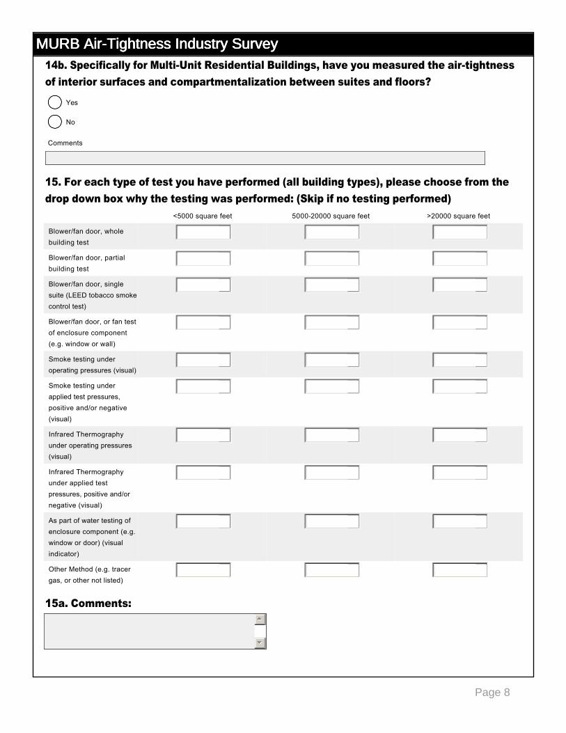
Page 8
MURB Air-Tightness Industry SurveyMURB Air-Tightness Industry SurveyMURB Air-Tightness Industry SurveyMURB Air-Tightness Industry Survey14b. Specifically for MultiUnit Residential Buildings, have you measured the airtightness of interior surfaces and compartmentalization between suites and floors?
15. For each type of test you have performed (all building types), please choose from the drop down box why the testing was performed: (Skip if no testing performed)
15a. Comments:
<5000 square feet 500020000 square feet >20000 square feet
Blower/fan door, whole building test
6 6 6
Blower/fan door, partial building test
6 6 6
Blower/fan door, single suite (LEED tobacco smoke control test)
6 6 6
Blower/fan door, or fan test of enclosure component (e.g. window or wall)
6 6 6
Smoke testing under operating pressures (visual)
6 6 6
Smoke testing under applied test pressures, positive and/or negative (visual)
6 6 6
Infrared Thermography under operating pressures (visual)
6 6 6
Infrared Thermography under applied test pressures, positive and/or negative (visual)
6 6 6
As part of water testing of enclosure component (e.g. window or door) (visual indicator)
6 6 6
Other Method (e.g. tracer gas, or other not listed)
6 6 6
55
66
Yes
nmlkj
No
nmlkj
Comments
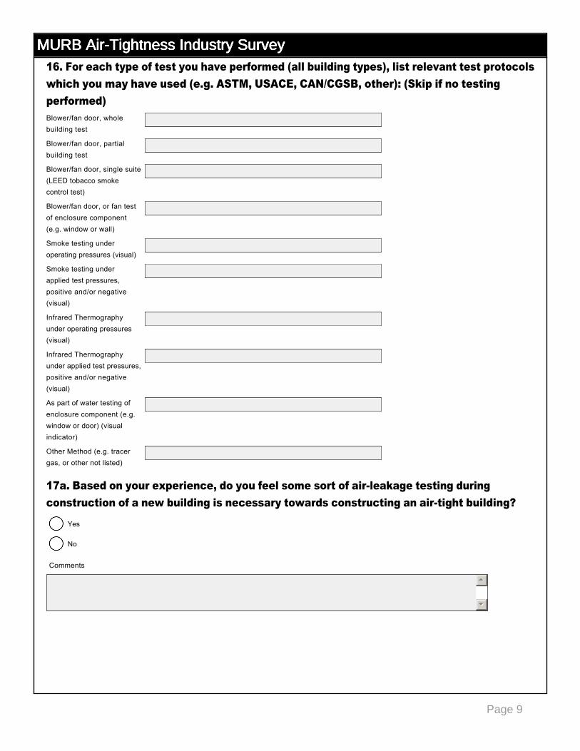
Page 9
MURB Air-Tightness Industry SurveyMURB Air-Tightness Industry SurveyMURB Air-Tightness Industry SurveyMURB Air-Tightness Industry Survey16. For each type of test you have performed (all building types), list relevant test protocols which you may have used (e.g. ASTM, USACE, CAN/CGSB, other): (Skip if no testing performed)
17a. Based on your experience, do you feel some sort of airleakage testing during construction of a new building is necessary towards constructing an airtight building?
Blower/fan door, whole building test
Blower/fan door, partial building test
Blower/fan door, single suite (LEED tobacco smoke control test)
Blower/fan door, or fan test of enclosure component (e.g. window or wall)
Smoke testing under operating pressures (visual)
Smoke testing under applied test pressures, positive and/or negative (visual)
Infrared Thermography under operating pressures (visual)
Infrared Thermography under applied test pressures, positive and/or negative (visual)
As part of water testing of enclosure component (e.g. window or door) (visual indicator)
Other Method (e.g. tracer gas, or other not listed)
Yes
nmlkj
No
nmlkj
Comments
55
66
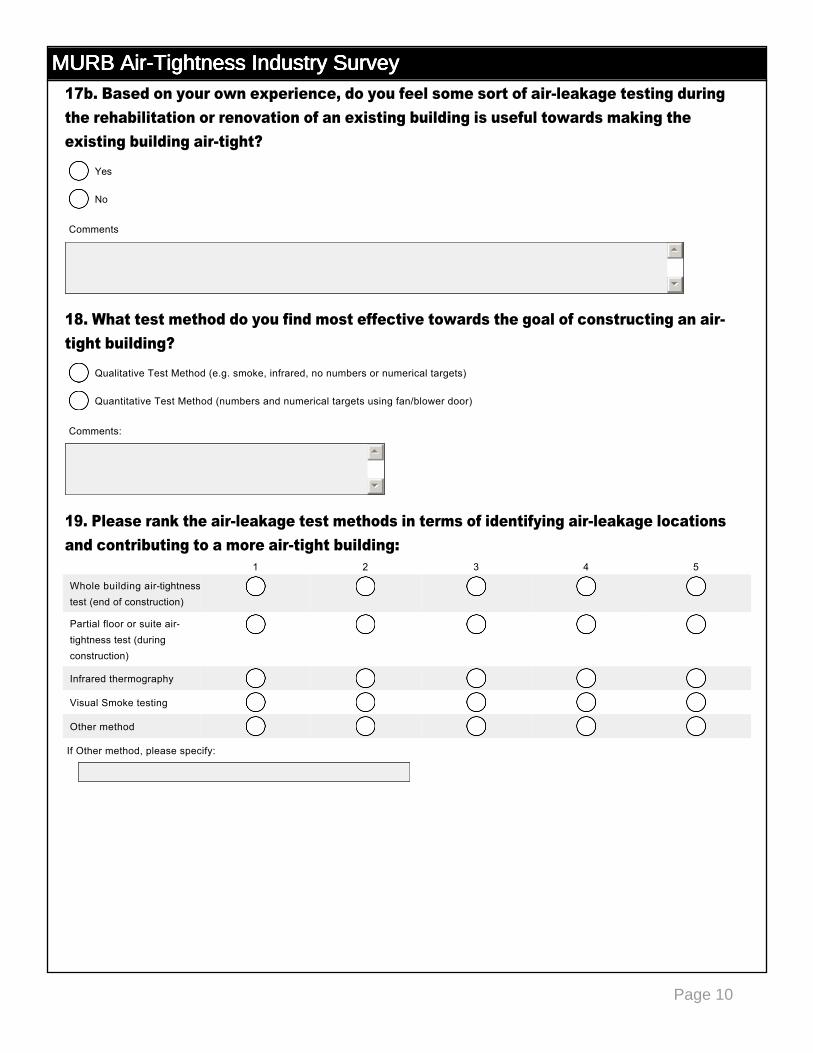
Page 10
MURB Air-Tightness Industry SurveyMURB Air-Tightness Industry SurveyMURB Air-Tightness Industry SurveyMURB Air-Tightness Industry Survey17b. Based on your own experience, do you feel some sort of airleakage testing during the rehabilitation or renovation of an existing building is useful towards making the existing building airtight?
18. What test method do you find most effective towards the goal of constructing an airtight building?
19. Please rank the airleakage test methods in terms of identifying airleakage locations and contributing to a more airtight building:
1 2 3 4 5
Whole building airtightness test (end of construction)
nmlkj nmlkj nmlkj nmlkj nmlkj
Partial floor or suite airtightness test (during construction)
nmlkj nmlkj nmlkj nmlkj nmlkj
Infrared thermography nmlkj nmlkj nmlkj nmlkj nmlkj
Visual Smoke testing nmlkj nmlkj nmlkj nmlkj nmlkj
Other method nmlkj nmlkj nmlkj nmlkj nmlkj
Yes
nmlkj
No
nmlkj
Comments
55
66
Qualitative Test Method (e.g. smoke, infrared, no numbers or numerical targets)
nmlkj
Quantitative Test Method (numbers and numerical targets using fan/blower door)
nmlkj
Comments:
55
66
If Other method, please specify:
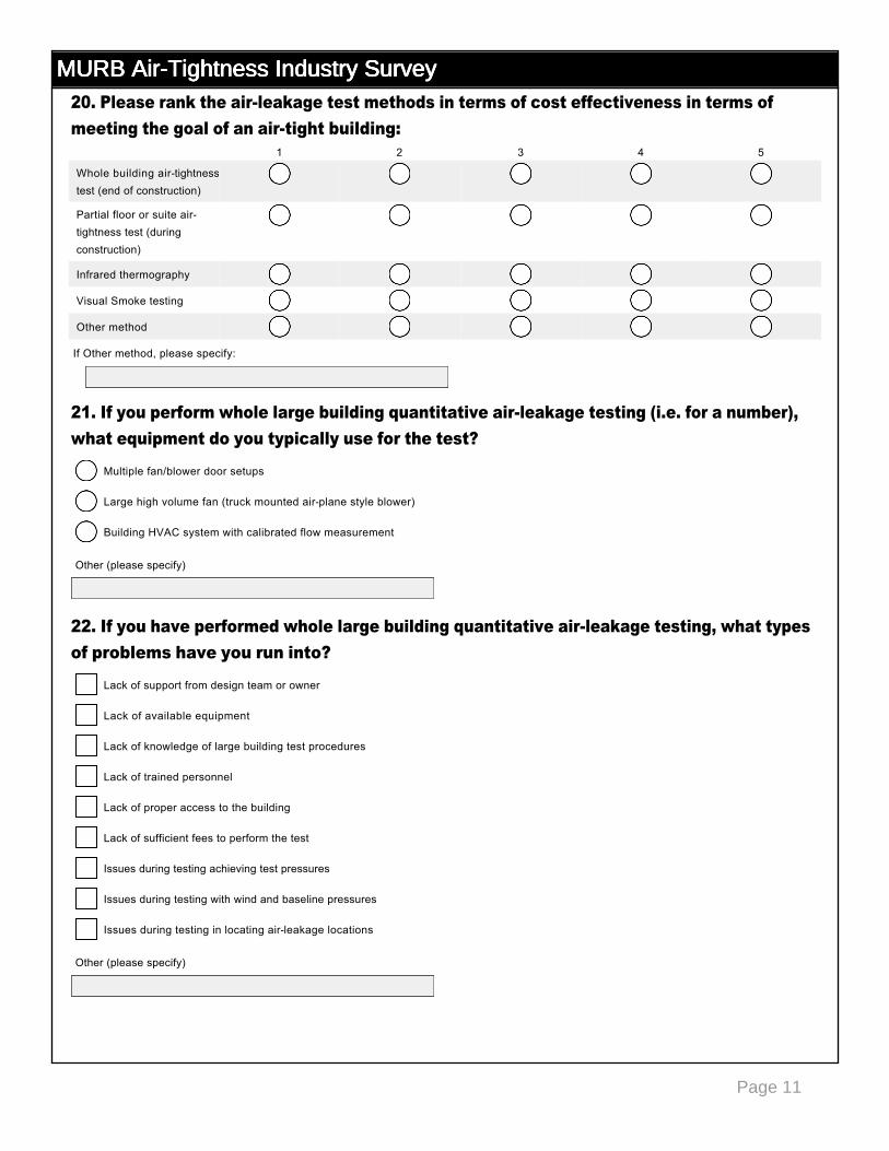
Page 11
MURB Air-Tightness Industry SurveyMURB Air-Tightness Industry SurveyMURB Air-Tightness Industry SurveyMURB Air-Tightness Industry Survey20. Please rank the airleakage test methods in terms of cost effectiveness in terms of meeting the goal of an airtight building:
21. If you perform whole large building quantitative airleakage testing (i.e. for a number), what equipment do you typically use for the test?
22. If you have performed whole large building quantitative airleakage testing, what types of problems have you run into?
1 2 3 4 5
Whole building airtightness test (end of construction)
nmlkj nmlkj nmlkj nmlkj nmlkj
Partial floor or suite airtightness test (during construction)
nmlkj nmlkj nmlkj nmlkj nmlkj
Infrared thermography nmlkj nmlkj nmlkj nmlkj nmlkj
Visual Smoke testing nmlkj nmlkj nmlkj nmlkj nmlkj
Other method nmlkj nmlkj nmlkj nmlkj nmlkj
If Other method, please specify:
Multiple fan/blower door setups
nmlkj
Large high volume fan (truck mounted airplane style blower)
nmlkj
Building HVAC system with calibrated flow measurement
nmlkj
Other (please specify)
Lack of support from design team or owner
gfedc
Lack of available equipment
gfedc
Lack of knowledge of large building test procedures
gfedc
Lack of trained personnel
gfedc
Lack of proper access to the building
gfedc
Lack of sufficient fees to perform the test
gfedc
Issues during testing achieving test pressures
gfedc
Issues during testing with wind and baseline pressures
gfedc
Issues during testing in locating airleakage locations
gfedc
Other (please specify)
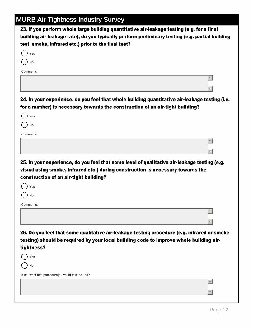
Page 12
MURB Air-Tightness Industry SurveyMURB Air-Tightness Industry SurveyMURB Air-Tightness Industry SurveyMURB Air-Tightness Industry Survey23. If you perform whole large building quantitative airleakage testing (e.g. for a final building air leakage rate), do you typically perform preliminary testing (e.g. partial building test, smoke, infrared etc.) prior to the final test?
24. In your experience, do you feel that whole building quantitative airleakage testing (i.e. for a number) is necessary towards the construction of an airtight building?
25. In your experience, do you feel that some level of qualitative airleakage testing (e.g. visual using smoke, infrared etc.) during construction is necessary towards the construction of an airtight building?
26. Do you feel that some qualitative airleakage testing procedure (e.g. infrared or smoke testing) should be required by your local building code to improve whole building airtightness?
Yes
nmlkj
No
nmlkj
Comments
55
66
Yes
nmlkj
No
nmlkj
Comments
55
66
Yes
nmlkj
No
nmlkj
Comments:
55
66
Yes
nmlkj
No
nmlkj
If so, what test procedure(s) would this include?
55
66
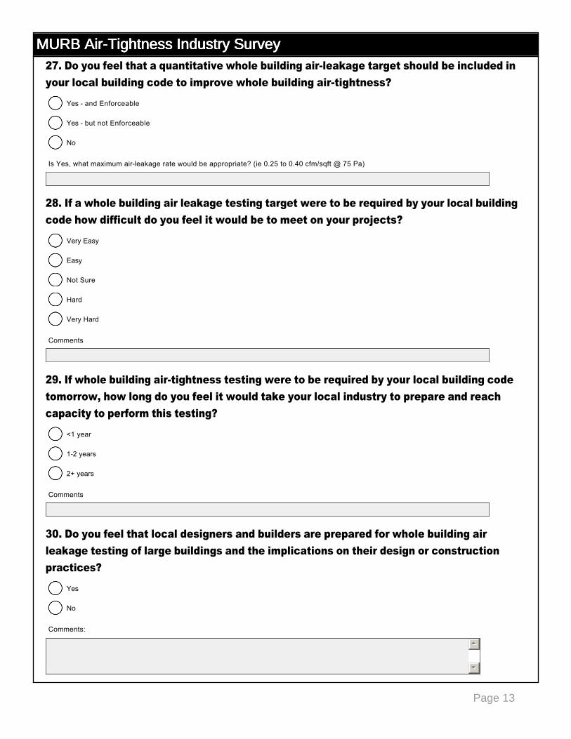
Page 13
MURB Air-Tightness Industry SurveyMURB Air-Tightness Industry SurveyMURB Air-Tightness Industry SurveyMURB Air-Tightness Industry Survey27. Do you feel that a quantitative whole building airleakage target should be included in your local building code to improve whole building airtightness?
28. If a whole building air leakage testing target were to be required by your local building code how difficult do you feel it would be to meet on your projects?
29. If whole building airtightness testing were to be required by your local building code tomorrow, how long do you feel it would take your local industry to prepare and reach capacity to perform this testing?
30. Do you feel that local designers and builders are prepared for whole building air leakage testing of large buildings and the implications on their design or construction practices?
Yes and Enforceable
nmlkj
Yes but not Enforceable
nmlkj
No
nmlkj
Is Yes, what maximum airleakage rate would be appropriate? (ie 0.25 to 0.40 cfm/sqft @ 75 Pa)
Very Easy
nmlkj
Easy
nmlkj
Not Sure
nmlkj
Hard
nmlkj
Very Hard
nmlkj
Comments
<1 year
nmlkj
12 years
nmlkj
2+ years
nmlkj
Comments
Yes
nmlkj
No
nmlkj
Comments:
55
66

Page 14
MURB Air-Tightness Industry SurveyMURB Air-Tightness Industry SurveyMURB Air-Tightness Industry SurveyMURB Air-Tightness Industry Survey
31. Do you feel that your local airleakage testing agencies and/or consultants are prepared to perform whole building air leakage testing of large buildings, or could be if the code requirement were to exist?
32. If you feel that there isn't currently local capacity to perform airtightness testing of large buildings what would be needed to improve this?
33. Do you have any airtightness measurements from MultiUnit Residential Buildings which you have tested and could be included in the research study? Any identifying information about the building is not required and the results will be aggregated with data from other buildings to estimate current airtightness levels. If you agree we will contact you by email to collect this data.
Thank you.
Yes Already have capacity
nmlkj
Yes Capacity could easily be met if required
nmlkj
Unsure
nmlkj
No No local capacity
nmlkj
No No local interest
nmlkj
Comments:
55
66
Local Testing Agency or Consultants from out of town
gfedc
Training and Education of local firms
gfedc
Testing Equipment
gfedc
Comments
Yes
nmlkj
No
nmlkj

Appendix C
Airtigh
tness D
atabase D
ata Collectio
n Fo
rm
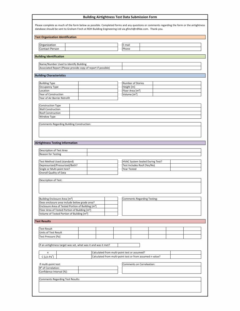
If multi‐point test:
R² of Correlation:
Confidence Interval [%]:
Comments Regarding Test Results:
Comments on Correleation:
Test Organization Identification
Test Results
Does enclosure area include below grade area?
Calculated from multi‐point test or assumed?
Calculated from multi‐point test or from assumed n value?
Test Result
Units of Test Result
Test Pressure [Pa]
n
C [L/s∙Pan]
If an airtightness target was set, what was it and was it met?
Comments Regarding Testing:Building Enclosure Area [m²]
Enclosure Area of Tested Portion of Building [m²]
Floor Area of Tested Portion of Building [m²]
Volume of Tested Portion of Building [m³]
Building Airtightness Test Data Submission Form
Overall Quality of Data
HVAC System Sealed During Test?
Test Includes Roof (Yes/No)
Year Tested
Building Type
Occupancy Type
Description of Test Area
Reason for Testing
Test Method Used (standard)
Depresurized/Pressurized/Both?
Single or Multi‐point test?
Year of Construction
Year of Air Barrier Retrofit
Window Type
Description of Test:
Airtightness Testing Information
Number of Stories
Height [m]
Floor Area [m²]
Volume [m³]
Please complete as much of the form below as possible. Completed forms and any questions or comments regarding the form or the airtightness
database should be sent to Graham Finch at RDH Building Engineering Ltd via [email protected]. Thank‐you.
Comments Regarding Building Construction:
E‐mail
Phone
Construction Type
Wall Construction
Roof Construction
Name/Number Used to Identify Building
Associated Report (Please provide copy of report if possible)
OrganizationContact Person
Building Identification
Building Characteristics
Location