cmm - asiaaerotechnics.comasiaaerotechnics.com/imr/techpubs/files/suasa airlines/9msua_rka... ·...
TRANSCRIPT
COMPONENT MAINTENANCE MANUAL33700002/33700005/33700006
TO ALL HOLDERS OF PACIFIC SCIENTIFIC HTL/KIN-TECH DIVISIONCOMPONENT MAINTENANCE MANUAL ATA 26-22-30
FOR P/N 33700002, P/N 33700005, AND P/N 33700006-1 DATED JUL 15/03
THIS SHEET TRANSMITS REVISION NO. 11
DATED MAY 01/14
HIGHLIGHTS
We reprinted this manual in its entirety. Please replace all of the pages of your manual with this revision. We made general format and layout changes in addition to technical changes.
All callouts to IPL item numbers in WARNINGS and CAUTIONS have been removed.
Chapter/Section and Page No. Description of Change
Record of Revisions Listed the revision number and date.
List of Effective Pages
Revised date.
Table of Contents Updated to latest revision.
List of Figures Updated to latest revision.
List of Tables Updated to latest revision.
Introduction Updated Pacific Scientific Company address from Duarte, CA to Simi Valley, CA. Removed the Dallas Service Center.
Description and Operation, 1 - 5
Revised voltages in Operation. Revised Figure 1 (schematics). Revised Table 1.
Assembly, 704 Updated installation torque for pressure gauge and switch.
Fits and Clearances, 801
Updated installation torque for pressure gauge and switch. Updated fill boss height.
Illustrated Parts List, 1001, 1009, 1010
Updated Pacific Scientific Company address from Duarte, CA to Simi Valley, CA. Added item numbers -35B and -102. Corrected nomenclature for items -15, 25, 30, -30A, -30B, 35, -35A, -65C, and 85.
26-22-30 Page 1May 01/14
Highlights

COMPONENT MAINTENANCE MANUAL33700002/33700005/33700006
THIS IS A BLANK PAGE
26-22-30 Page 2May 01/14
Highlights
HTL/Kin-Tech Division
Component Maintenance Manualwith
Illustrated Parts List
26-22-30 Page T-1May 01/14
224 CUBIC INCHFIRE EXTINGUISHERS
HTL PART NUMBERS337000023370000533700006-1
26-22-30 Page T-2May 01/14
COMPONENT MAINTENANCE MANUAL33700002/33700005/33700006
CONFIDENTIALITY NOTICE
This document contains confidential and proprietary information, which is the property of HTL/Kin-Tech Division of Pacific Scientific Company and shall not be copied or reproduced, in whole or in part, or the contents divulged or used for manufacture, without the specific written permission of HTL/Kin-Tech Division of Pacific Scientific Company. Recipient, by acceptance, use, or retention of this document, acknowledges and agrees to the foregoing and covenants to maintain the contents in confidence.
TECHNICAL DATA EXPORT NOTICE
This data is exported pursuant to the requirements of the United States Government Export Administration Act of 1969, as amended, and promulgated by the export administration regulations as issued by the U.S. Department of Commerce. The data may not be reproduced and shall not, without the written permission of HTL/Kin-Tech Division of Pacific Scientific, be used for purposes of manufacture, or shall it be disclosed, reexported nor transmitted directly or indirectly from the importing foreign country to any person, government, governmental entity or institution of another foreign government. It is understood and agreed that the use of this data shall be limited to the following purposes: (i) use by Support Service Contractors (except for manufacture), (ii) emergency repair or overhaul work, (iii) receiving inspection of hardware, (iv) evaluation of a bid or proposal. By acknowledgment of receipt of data containing this legend, importer agrees to comply thereto.
CRITICALITY NOTICE, PMA PARTS USAGE
The equipment described in this document is aviation safety equipment and has been tested and qualified to stringent performance requirements. Subcomponent tolerances, material properties, metallurgy, interfaces, and interactions of the components are critical to the proper performance of the subsystems and their airworthiness, qualification, and certification status.
Non-Pacific Scientific PMA parts and components are available in the marketplace. These parts are not recognized by Pacific Scientific and have not been tested, nor qualified for use in Pacific Scientific products by Pacific Scientific Company. Since we have no control or knowledge of the integrity of these parts when allied to our systems, Pacific Scientific must make the following statements concerning non-Pacific Scientific components manufactured under PMA authority:
THE USE OF NON-PACIFIC SCIENTIFIC COMPANY PARTS WILL IMMEDIATELY VOID ANY AND ALL WARRANTIES.
PACIFIC SCIENTIFIC COMPANY WAIVES ALL RESPONSIBILITY OR LIABILITY FOR ANY NON-PACIFIC SCIENTIFIC COMPANY PART INSTALLATION.
PACIFIC SCIENTIFIC COMPANY WAIVES ALL RESPONSIBILTY OR LIABILITY FOR THE PERFORMANCE OF ANY PACIFIC SCIENTIFIC PRODUCT THAT CONTAINS NON-PACIFIC SCIENTIFIC COMPANY PARTS.
Should you wish to return any Pacific Scientific part that contains NON-PACIFIC SCIENTIFIC COMPANY subcomponents for return to zero time condition, a quotation will be provided. Completion of this service will validate the integrity of the product and reinstate standard warranties for the product.
COMPONENT MAINTENANCE MANUAL33700002/33700005/33700006
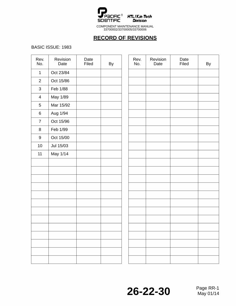
RECORD OF REVISIONS
BASIC ISSUE: 1983
Rev.No.
RevisionDate
DateFiled By
Rev.No.
RevisionDate
DateFiled By
1 Oct 23/84
2 Oct 15/86
3 Feb 1/88
4 May 1/89
5 Mar 15/92
6 Aug 1/94
7 Oct 15/96
8 Feb 1/99
9 Oct 15/00
10 Jul 15/03
11 May 1/14
26-22-30 Page RR-1May 01/14

COMPONENT MAINTENANCE MANUAL33700002/33700005/33700006
THIS IS A BLANK PAGE
26-22-30 Page RR-2May 01/14
COMPONENT MAINTENANCE MANUAL33700002/33700005/33700006
RECORD OF TEMPORARY REVISIONS
Rev.No.
IssueDate
DateInserted By
DateRemoved By
26-22-30-1 Sep 4/86 Oct 15/86
26-22-30 Page RTR-1May 01/14

COMPONENT MAINTENANCE MANUAL33700002/33700005/33700006
THIS IS A BLANK PAGE
26-22-30 Page RTR-2May 01/14
COMPONENT MAINTENANCE MANUAL33700002/33700005/33700006
SERVICE BULLETIN LIST
Service Bulletin Issue Date Date Incorporated
83-2A Jun 1/91 Aug 1/94
83-32 Jun 1/91 Aug 1/94
33700002-26-1 Aug 1/89 Aug 1/94
26-22-30 Page SBL-1May 01/14

COMPONENT MAINTENANCE MANUAL33700002/33700005/33700006
THIS IS A BLANK PAGE
26-22-30 Page SBL-2May 01/14
COMPONENT MAINTENANCE MANUAL33700002/33700005/33700006
1999 by Pacific Scientific HTL/Kin-Tech DivisionRevised 2014
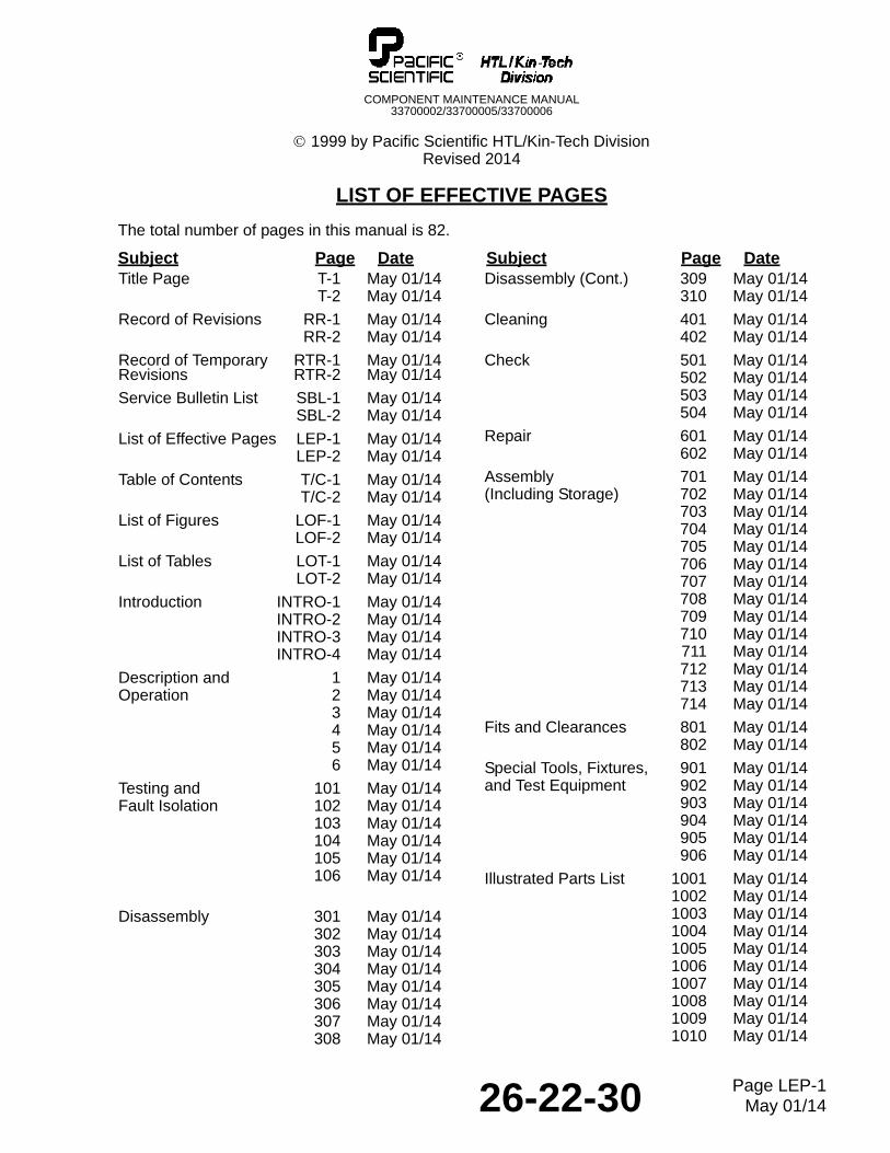
LIST OF EFFECTIVE PAGES
The total number of pages in this manual is 82.
Subject Page Date Subject Page DateTitle Page T-1 May 01/14
T-2 May 01/14
Record of Revisions RR-1 May 01/14RR-2 May 01/14
Record of Temporary RTR-1 May 01/14Revisions RTR-2 May 01/14
Service Bulletin List SBL-1 May 01/14SBL-2 May 01/14
List of Effective Pages LEP-1 May 01/14LEP-2 May 01/14
Table of Contents T/C-1 May 01/14T/C-2 May 01/14
List of Figures LOF-1 May 01/14LOF-2 May 01/14
List of Tables LOT-1 May 01/14LOT-2 May 01/14
Introduction INTRO-1 May 01/14INTRO-2 May 01/14INTRO-3 May 01/14INTRO-4 May 01/14
Description and 1 May 01/14Operation 2 May 01/14
3 May 01/144 May 01/145 May 01/146 May 01/14
Testing and 101 May 01/14Fault Isolation 102 May 01/14
103 May 01/14104 May 01/14105 May 01/14106 May 01/14
Disassembly 301 May 01/14302 May 01/14303 May 01/14304 May 01/14305 May 01/14306 May 01/14307 May 01/14308 May 01/14
Disassembly (Cont.) 309 May 01/14310 May 01/14
Cleaning 401 May 01/14402 May 01/14
Check 501 May 01/14502 May 01/14503 May 01/14504 May 01/14
Repair 601 May 01/14602 May 01/14
Assembly 701 May 01/14(Including Storage) 702 May 01/14
703 May 01/14704 May 01/14705 May 01/14706 May 01/14707 May 01/14708 May 01/14709 May 01/14710 May 01/14711 May 01/14712 May 01/14713 May 01/14714 May 01/14
Fits and Clearances 801 May 01/14802 May 01/14
Special Tools, Fixtures, 901 May 01/14and Test Equipment 902 May 01/14
903 May 01/14904 May 01/14905 May 01/14906 May 01/14
Illustrated Parts List 1001 May 01/141002 May 01/141003 May 01/141004 May 01/141005 May 01/141006 May 01/141007 May 01/141008 May 01/141009 May 01/141010 May 01/14
26-22-30 Page LEP-1May 01/14

COMPONENT MAINTENANCE MANUAL33700002/33700005/33700006
THIS IS A BLANK PAGE
26-22-30 Page LEP-2May 01/14
COMPONENT MAINTENANCE MANUAL33700002/33700005/33700006
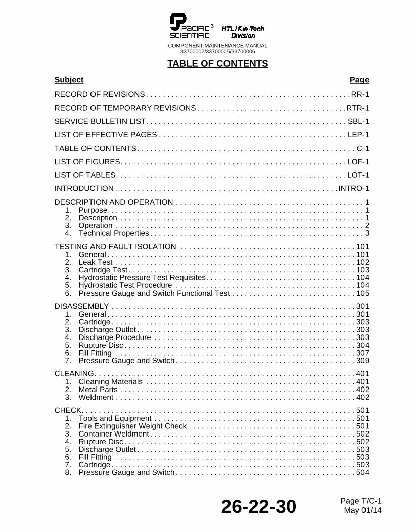
TABLE OF CONTENTS
Subject Page
RECORD OF REVISIONS. . . . . . . . . . . . . . . . . . . . . . . . . . . . . . . . . . . . . . . . . . . . . . . .RR-1
RECORD OF TEMPORARY REVISIONS . . . . . . . . . . . . . . . . . . . . . . . . . . . . . . . . . . .RTR-1
SERVICE BULLETIN LIST. . . . . . . . . . . . . . . . . . . . . . . . . . . . . . . . . . . . . . . . . . . . . . . SBL-1
LIST OF EFFECTIVE PAGES . . . . . . . . . . . . . . . . . . . . . . . . . . . . . . . . . . . . . . . . . . . . LEP-1
TABLE OF CONTENTS. . . . . . . . . . . . . . . . . . . . . . . . . . . . . . . . . . . . . . . . . . . . . . . . . . . C-1
LIST OF FIGURES. . . . . . . . . . . . . . . . . . . . . . . . . . . . . . . . . . . . . . . . . . . . . . . . . . . . . LOF-1
LIST OF TABLES. . . . . . . . . . . . . . . . . . . . . . . . . . . . . . . . . . . . . . . . . . . . . . . . . . . . . . LOT-1
INTRODUCTION . . . . . . . . . . . . . . . . . . . . . . . . . . . . . . . . . . . . . . . . . . . . . . . . . . . . INTRO-1
DESCRIPTION AND OPERATION . . . . . . . . . . . . . . . . . . . . . . . . . . . . . . . . . . . . . . . . . . . . 11. Purpose . . . . . . . . . . . . . . . . . . . . . . . . . . . . . . . . . . . . . . . . . . . . . . . . . . . . . . . . . . . 12. Description . . . . . . . . . . . . . . . . . . . . . . . . . . . . . . . . . . . . . . . . . . . . . . . . . . . . . . . . . 13. Operation . . . . . . . . . . . . . . . . . . . . . . . . . . . . . . . . . . . . . . . . . . . . . . . . . . . . . . . . . . 24. Technical Properties . . . . . . . . . . . . . . . . . . . . . . . . . . . . . . . . . . . . . . . . . . . . . . . . . . 3
TESTING AND FAULT ISOLATION . . . . . . . . . . . . . . . . . . . . . . . . . . . . . . . . . . . . . . . . . 1011. General . . . . . . . . . . . . . . . . . . . . . . . . . . . . . . . . . . . . . . . . . . . . . . . . . . . . . . . . . . 1012. Leak Test . . . . . . . . . . . . . . . . . . . . . . . . . . . . . . . . . . . . . . . . . . . . . . . . . . . . . . . . 1023. Cartridge Test . . . . . . . . . . . . . . . . . . . . . . . . . . . . . . . . . . . . . . . . . . . . . . . . . . . . . 1034. Hydrostatic Pressure Test Requisites. . . . . . . . . . . . . . . . . . . . . . . . . . . . . . . . . . . 1045. Hydrostatic Test Procedure . . . . . . . . . . . . . . . . . . . . . . . . . . . . . . . . . . . . . . . . . . 1046. Pressure Gauge and Switch Functional Test . . . . . . . . . . . . . . . . . . . . . . . . . . . . . 105
DISASSEMBLY . . . . . . . . . . . . . . . . . . . . . . . . . . . . . . . . . . . . . . . . . . . . . . . . . . . . . . . . . 3011. General . . . . . . . . . . . . . . . . . . . . . . . . . . . . . . . . . . . . . . . . . . . . . . . . . . . . . . . . . . 3012. Cartridge . . . . . . . . . . . . . . . . . . . . . . . . . . . . . . . . . . . . . . . . . . . . . . . . . . . . . . . . . 3033. Discharge Outlet . . . . . . . . . . . . . . . . . . . . . . . . . . . . . . . . . . . . . . . . . . . . . . . . . . . 3034. Discharge Procedure . . . . . . . . . . . . . . . . . . . . . . . . . . . . . . . . . . . . . . . . . . . . . . . 3035. Rupture Disc . . . . . . . . . . . . . . . . . . . . . . . . . . . . . . . . . . . . . . . . . . . . . . . . . . . . . . 3046. Fill Fitting . . . . . . . . . . . . . . . . . . . . . . . . . . . . . . . . . . . . . . . . . . . . . . . . . . . . . . . . 3077. Pressure Gauge and Switch . . . . . . . . . . . . . . . . . . . . . . . . . . . . . . . . . . . . . . . . . . 309
CLEANING. . . . . . . . . . . . . . . . . . . . . . . . . . . . . . . . . . . . . . . . . . . . . . . . . . . . . . . . . . . . . 4011. Cleaning Materials . . . . . . . . . . . . . . . . . . . . . . . . . . . . . . . . . . . . . . . . . . . . . . . . . 4012. Metal Parts . . . . . . . . . . . . . . . . . . . . . . . . . . . . . . . . . . . . . . . . . . . . . . . . . . . . . . . 4023. Weldment . . . . . . . . . . . . . . . . . . . . . . . . . . . . . . . . . . . . . . . . . . . . . . . . . . . . . . . . 402
CHECK. . . . . . . . . . . . . . . . . . . . . . . . . . . . . . . . . . . . . . . . . . . . . . . . . . . . . . . . . . . . . . . . 5011. Tools and Equipment . . . . . . . . . . . . . . . . . . . . . . . . . . . . . . . . . . . . . . . . . . . . . . . 5012. Fire Extinguisher Weight Check . . . . . . . . . . . . . . . . . . . . . . . . . . . . . . . . . . . . . . . 5013. Container Weldment . . . . . . . . . . . . . . . . . . . . . . . . . . . . . . . . . . . . . . . . . . . . . . . . 5024. Rupture Disc . . . . . . . . . . . . . . . . . . . . . . . . . . . . . . . . . . . . . . . . . . . . . . . . . . . . . . 5025. Discharge Outlet . . . . . . . . . . . . . . . . . . . . . . . . . . . . . . . . . . . . . . . . . . . . . . . . . . . 5036. Fill Fitting . . . . . . . . . . . . . . . . . . . . . . . . . . . . . . . . . . . . . . . . . . . . . . . . . . . . . . . . 5037. Cartridge . . . . . . . . . . . . . . . . . . . . . . . . . . . . . . . . . . . . . . . . . . . . . . . . . . . . . . . . . 5038. Pressure Gauge and Switch . . . . . . . . . . . . . . . . . . . . . . . . . . . . . . . . . . . . . . . . . . 504
26-22-30 Page T/C-1May 01/14
COMPONENT MAINTENANCE MANUAL33700002/33700005/33700006
Subject Page
REPAIR . . . . . . . . . . . . . . . . . . . . . . . . . . . . . . . . . . . . . . . . . . . . . . . . . . . . . . . . . . . . . . . 6011. General . . . . . . . . . . . . . . . . . . . . . . . . . . . . . . . . . . . . . . . . . . . . . . . . . . . . . . . . . 6012. Replacement of Bonded Plates . . . . . . . . . . . . . . . . . . . . . . . . . . . . . . . . . . . . . . . 601
ASSEMBLY (INCLUDING STORAGE) . . . . . . . . . . . . . . . . . . . . . . . . . . . . . . . . . . . . . . . 7011. General . . . . . . . . . . . . . . . . . . . . . . . . . . . . . . . . . . . . . . . . . . . . . . . . . . . . . . . . . 7012. Rupture Disc . . . . . . . . . . . . . . . . . . . . . . . . . . . . . . . . . . . . . . . . . . . . . . . . . . . . . 7033. Pressure Gauge and Switch . . . . . . . . . . . . . . . . . . . . . . . . . . . . . . . . . . . . . . . . . 7044. Extinguisher Recharge. . . . . . . . . . . . . . . . . . . . . . . . . . . . . . . . . . . . . . . . . . . . . . 7055. Fill Fitting . . . . . . . . . . . . . . . . . . . . . . . . . . . . . . . . . . . . . . . . . . . . . . . . . . . . . . . . 7116. Discharge Outlet and Cartridge . . . . . . . . . . . . . . . . . . . . . . . . . . . . . . . . . . . . . . . 7137. Storage Instructions . . . . . . . . . . . . . . . . . . . . . . . . . . . . . . . . . . . . . . . . . . . . . . . . 713
FITS AND CLEARANCES. . . . . . . . . . . . . . . . . . . . . . . . . . . . . . . . . . . . . . . . . . . . . . . . . 8011. Torque Limits . . . . . . . . . . . . . . . . . . . . . . . . . . . . . . . . . . . . . . . . . . . . . . . . . . . . . 8012. Minimum Height Dimensions for Fill and Discharge Bosses . . . . . . . . . . . . . . . . . 801
SPECIAL TOOLS, FIXTURES, AND TEST EQUIPMENT . . . . . . . . . . . . . . . . . . . . . . . . 9011. Special Tools, Fixtures, and Equipment. . . . . . . . . . . . . . . . . . . . . . . . . . . . . . . . . 901
ILLUSTRATED PARTS LIST . . . . . . . . . . . . . . . . . . . . . . . . . . . . . . . . . . . . . . . . . . . . . 10011. Introduction . . . . . . . . . . . . . . . . . . . . . . . . . . . . . . . . . . . . . . . . . . . . . . . . . . . . . 10012. Manufacturer Names and Address . . . . . . . . . . . . . . . . . . . . . . . . . . . . . . . . . . . 10013. Explanation of Numerical Index Entries . . . . . . . . . . . . . . . . . . . . . . . . . . . . . . . . 10024. Explanation of Detail Parts List Entries . . . . . . . . . . . . . . . . . . . . . . . . . . . . . . . . 10025. Numerical Index . . . . . . . . . . . . . . . . . . . . . . . . . . . . . . . . . . . . . . . . . . . . . . . . . . 10056. Detailed Parts List . . . . . . . . . . . . . . . . . . . . . . . . . . . . . . . . . . . . . . . . . . . . . . . . 1007
26-22-30 Page T/C-2May 01/14
COMPONENT MAINTENANCE MANUAL33700002/33700005/33700006
LIST OF FIGURES
Figure Page
Figure 1. Cartridge and Pressure Gauge and Switch Schematics . . . . . . . . . . . . . . . . . . . . 2Figure 2. Primary Components . . . . . . . . . . . . . . . . . . . . . . . . . . . . . . . . . . . . . . . . . . . . . . . 3Figure 101. Cartridge Test Setup . . . . . . . . . . . . . . . . . . . . . . . . . . . . . . . . . . . . . . . . . . . 104Figure 301. Disassembly Sequence Chart . . . . . . . . . . . . . . . . . . . . . . . . . . . . . . . . . . . . 301Figure 302. Discharge and Recovery Setup . . . . . . . . . . . . . . . . . . . . . . . . . . . . . . . . . . . 304Figure 303. Rupture Disc Removal . . . . . . . . . . . . . . . . . . . . . . . . . . . . . . . . . . . . . . . . . . 306Figure 304. Fill Fitting Removal . . . . . . . . . . . . . . . . . . . . . . . . . . . . . . . . . . . . . . . . . . . . 308Figure 501. Cartridge Disposal Setup . . . . . . . . . . . . . . . . . . . . . . . . . . . . . . . . . . . . . . . . 504Figure 701. Rupture Disc Installation . . . . . . . . . . . . . . . . . . . . . . . . . . . . . . . . . . . . . . . . 704Figure 702. Pressure Gauge and Switch Orientation . . . . . . . . . . . . . . . . . . . . . . . . . . . . 705Figure 703. Fire Extinguisher Refill Setup (Sheet 1 of 2) . . . . . . . . . . . . . . . . . . . . . . . . . 706Figure 704. Charging Fixture Installation on Fill Fitting. . . . . . . . . . . . . . . . . . . . . . . . . . . 709Figure 705. Fill Fitting Installation . . . . . . . . . . . . . . . . . . . . . . . . . . . . . . . . . . . . . . . . . . . 712Figure 801. Minimum Height Dimensions for Fill and Discharge Bosses . . . . . . . . . . . . . 801IPL Figure 1. 224 Cubic Inch Dual Outlet Fire Extinguisher . . . . . . . . . . . . . . . . . . . . . . 1008
26-22-30 Page LOF-1May 01/14

COMPONENT MAINTENANCE MANUAL33700002/33700005/33700006
THIS IS A BLANK PAGE
26-22-30 Page LOF-2May 01/14
COMPONENT MAINTENANCE MANUAL33700002/33700005/33700006
LIST OF TABLES
Table Page
Table 1. Technical Properties for 224 Cubic Inch Fire Extinguisher . . . . . . . . . . . . . . . . . . . 3Table 101. Test Equipment and Materials . . . . . . . . . . . . . . . . . . . . . . . . . . . . . . . . . . . . 101Table 301. Disassembly Tools and Materials . . . . . . . . . . . . . . . . . . . . . . . . . . . . . . . . . . 302Table 401. Cleaning Materials . . . . . . . . . . . . . . . . . . . . . . . . . . . . . . . . . . . . . . . . . . . . . 401Table 501. Check Tools and Equipment . . . . . . . . . . . . . . . . . . . . . . . . . . . . . . . . . . . . . . 501Table 502. Maximum Fire Extinguisher Weight . . . . . . . . . . . . . . . . . . . . . . . . . . . . . . . . 502Table 601. Repair Tools and Materials . . . . . . . . . . . . . . . . . . . . . . . . . . . . . . . . . . . . . . . 601Table 701. Assembly Tools and Materials . . . . . . . . . . . . . . . . . . . . . . . . . . . . . . . . . . . . 701Table 702. Welding Schedule . . . . . . . . . . . . . . . . . . . . . . . . . . . . . . . . . . . . . . . . . . . . . . 702Table 703. Fire Extinguisher Refill Record . . . . . . . . . . . . . . . . . . . . . . . . . . . . . . . . . . . . 708Table 704. Nitrogen Charge Pressure Versus Temperature for P/N 33700002 and P/N
33700006-1 . . . . . . . . . . . . . . . . . . . . . . . . . . . . . . . . . . . . . . . . . . . . . . . . . 710Table 705. Nitrogen Charge Pressure Versus Temperature for P/N 33700005 . . . . . . . . 710Table 706. Charged Fire Extinguisher Weight . . . . . . . . . . . . . . . . . . . . . . . . . . . . . . . . . 710Table 707. Storage Materials . . . . . . . . . . . . . . . . . . . . . . . . . . . . . . . . . . . . . . . . . . . . . . 713Table 801. Torque Limits . . . . . . . . . . . . . . . . . . . . . . . . . . . . . . . . . . . . . . . . . . . . . . . . . 801Table 901. Special Tools, Fixtures, and Equipment . . . . . . . . . . . . . . . . . . . . . . . . . . . . . 901
26-22-30 Page LOT-1May 01/14

COMPONENT MAINTENANCE MANUAL33700002/33700005/33700006
THIS IS A BLANK PAGE
26-22-30 Page LOT-2May 01/14
COMPONENT MAINTENANCE MANUAL33700002/33700005/33700006
INTRODUCTION
1. Scope
A. This Component Maintenance Manual (CMM) contains the maintenance instructions and an illustrated parts list for the 224 Cubic Inch Fire Extinguisher. The fire extinguisher is manufactured by Pacific Scientific Company, HTL/Kin-Tech Division, Simi Valley, California.
2. Usage Guide
A. Refer to the Table of Contents to find the necessary procedures or maintenance data. This Manual is written to ATA 100, Revision 30 and AECMA Simplified English guidelines.
(1) Description and Operation gives the function, primary components, and technical properties of the fire extinguisher.
(2) Testing and Fault Isolation contains the test and fault isolation procedures.
(3) Disassembly contains the procedures to discharge the extinguishing agent and disassemble the fire extinguisher before repair or part replacement.
(4) Cleaning contains procedures to clean the fire extinguisher and components.
(5) Check contains the procedures to check the parts for too much wear, corrosion, and other damage.
(6) Repair contains the repair procedures.
(7) Assembly contains the procedures to reassemble, refill, and store the fire extinguisher.
(8) Fits and Clearances contains the assembly torque ranges and the minimum height dimensions for the fill, discharge, and switch bosses (as applicable).
(9) Special Tools, Fixtures, and Equipment describes the recommended special tools, fixtures, and test equipment.
(10) Illustrated Parts List contains the information needed to order spare parts. A numerical index and an exploded-view drawing are provided to help identify the parts.
B. The recommended tools and materials are given in each section. Equivalent items can be used.
3. Hydrostatic Regulations
A. This Component Maintenance Manual (CMM) contains hydrostatic regulations and procedures that are based on U. S. Department of Transportation 49 CFR. Refer to Hydrostatic Pressure Test Requisites in Testing and Fault Isolation for additional information.
4. Product Support Services
A. Product support services for the fire extinguisher are available from Pacific Scientific Company.
26-22-30 Page INTRO-1May 01/14
COMPONENT MAINTENANCE MANUAL33700002/33700005/33700006
B. For technical documentation, please contact:
PACIFIC SCIENTIFIC COMPANY Telephone: (305) 477-471111700 N.W. 102nd Road Suite 6 FAX: (305) 477-9799Miami, Florida 33178 U.S.A. SITA: MIAPSXD
C. For repair and overhaul, and spare parts please contact:
PACIFIC SCIENTIFIC COMPANY Telephone: (305) 477-471111700 N.W. 102nd Road Suite 6 FAX: (305) 477-9799Miami, Florida 33178 U.S.A. SITA: MIAPSXD
PACIFIC SCIENTIFIC LIMITED Telephone: 44 (1628) 682200Howarth Road FAX: 44 (1628) 682250Maidenhead AOG: 44 (7836) 228480Berkshire LS6 1AP, United Kingdom SITA: LHRPSCR
5. Verification Dates
Procedure DateTesting/Fault Isolation Jun 15/03Disassembly Jun 15/03Assembly Jun 15/03
6. Revision Service
A. Revised pages will be issued when necessary throughout the service life of the fire extinguisher. The revised part of the page will be identified by a change bar or capital R in the left margin.
7. Abbreviations and Unit Symbols
A. Abbreviations and unit symbols which may be used in this manual are defined below. All weights and measurements are given first in the English standard units followed by the metric equivalent in parentheses.
Assy - AssemblyATA - Air Transport Associationcfh - Cubic feet per hourCAGE - Commercial and
Government Entitycm - Centimeter
(1 cm = 0.394 inch)DC - Direct Current DOT - Department of
TransportationEFF - EffectivityFAA - Federal Aviation
AdministrationFIG. - FigureID - Inside DiameterIPL - Illustrated Parts List
kg - Kilogram (1 kg = 2.205 pounds)
kPag - Kilo Pascal-gauge (1 kPag = 0.15 psig)
m3/hr - Cubic meter per hourm - Meter
(1 m = 3.281 feet)mA - Milliampere mm - Millimeter
(1 mm = 0.0394 inch)N.m - Newton-meter
(1 N.m = 8.3 in-lb)NHA - Next Higher AssemblyNo. - NumberOD - Outside DiameterPara. - Paragraph
26-22-30 Page INTRO-2May 01/14
COMPONENT MAINTENANCE MANUAL33700002/33700005/33700006
P/N - Part Numberpsig - Pounds per square inch-
gaugeRF - Referencerpm - Revolutions per minute
SB - Service Bulletinsccs - Standard cubic centimeter
per secondV - VoltVDC - Voltage - Direct Current
26-22-30 Page INTRO-3May 01/14

COMPONENT MAINTENANCE MANUAL33700002/33700005/33700006
THIS IS A BLANK PAGE
26-22-30 Page INTRO-4May 01/14
COMPONENT MAINTENANCE MANUAL33700002/33700005/33700006
DESCRIPTION AND OPERATION
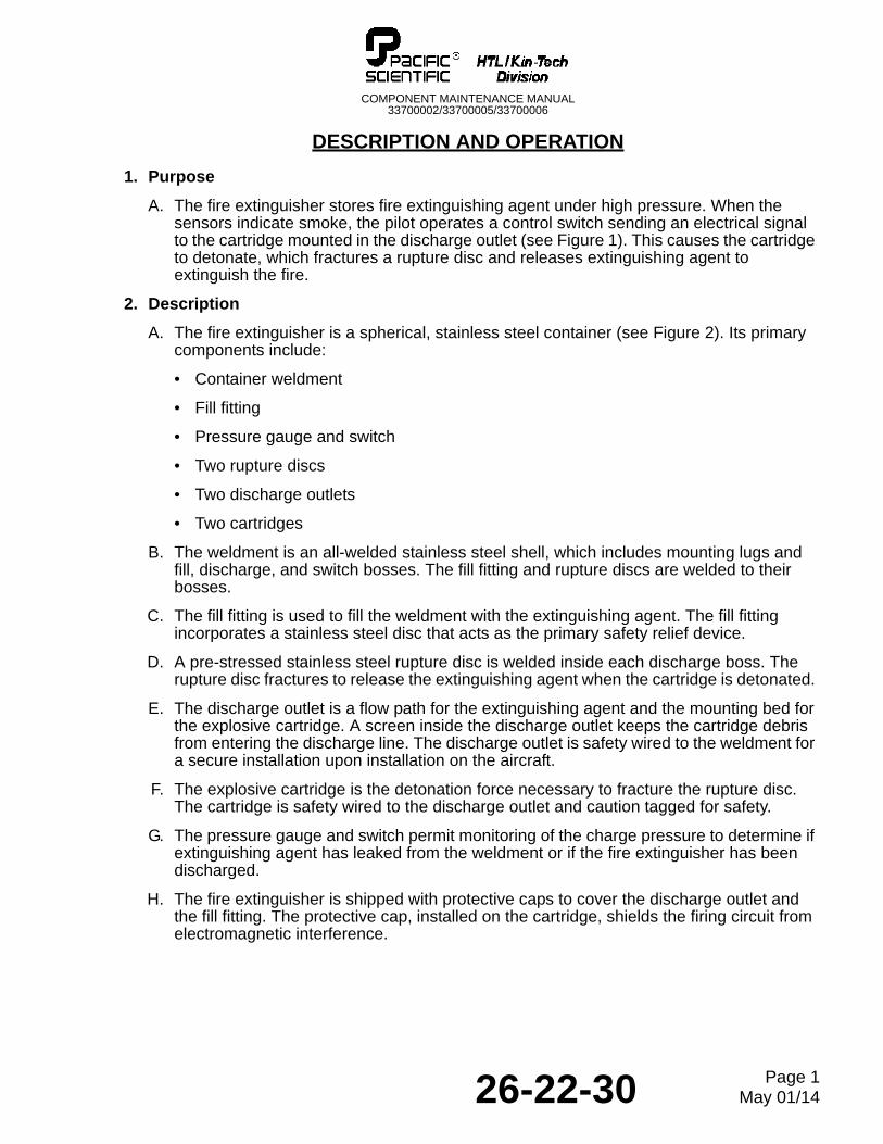
1. Purpose
A. The fire extinguisher stores fire extinguishing agent under high pressure. When the sensors indicate smoke, the pilot operates a control switch sending an electrical signal to the cartridge mounted in the discharge outlet (see Figure 1). This causes the cartridge to detonate, which fractures a rupture disc and releases extinguishing agent to extinguish the fire.
2. Description
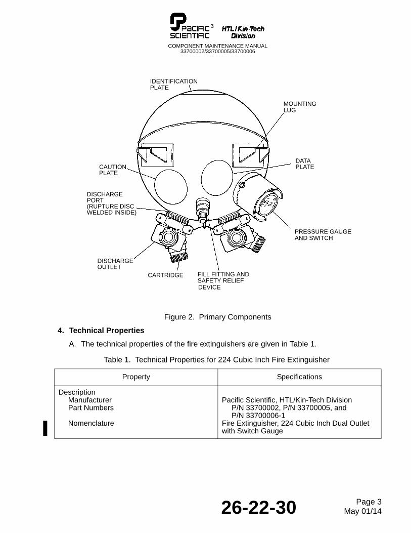
A. The fire extinguisher is a spherical, stainless steel container (see Figure 2). Its primary components include:
• Container weldment
• Fill fitting
• Pressure gauge and switch
• Two rupture discs
• Two discharge outlets
• Two cartridges
B. The weldment is an all-welded stainless steel shell, which includes mounting lugs and fill, discharge, and switch bosses. The fill fitting and rupture discs are welded to their bosses.
C. The fill fitting is used to fill the weldment with the extinguishing agent. The fill fitting incorporates a stainless steel disc that acts as the primary safety relief device.
D. A pre-stressed stainless steel rupture disc is welded inside each discharge boss. The rupture disc fractures to release the extinguishing agent when the cartridge is detonated.
E. The discharge outlet is a flow path for the extinguishing agent and the mounting bed for the explosive cartridge. A screen inside the discharge outlet keeps the cartridge debris from entering the discharge line. The discharge outlet is safety wired to the weldment for a secure installation upon installation on the aircraft.
F. The explosive cartridge is the detonation force necessary to fracture the rupture disc. The cartridge is safety wired to the discharge outlet and caution tagged for safety.
G. The pressure gauge and switch permit monitoring of the charge pressure to determine if extinguishing agent has leaked from the weldment or if the fire extinguisher has been discharged.
H. The fire extinguisher is shipped with protective caps to cover the discharge outlet and the fill fitting. The protective cap, installed on the cartridge, shields the firing circuit from electromagnetic interference.
26-22-30 Page 1May 01/14
COMPONENT MAINTENANCE MANUAL33700002/33700005/33700006
3. Operation
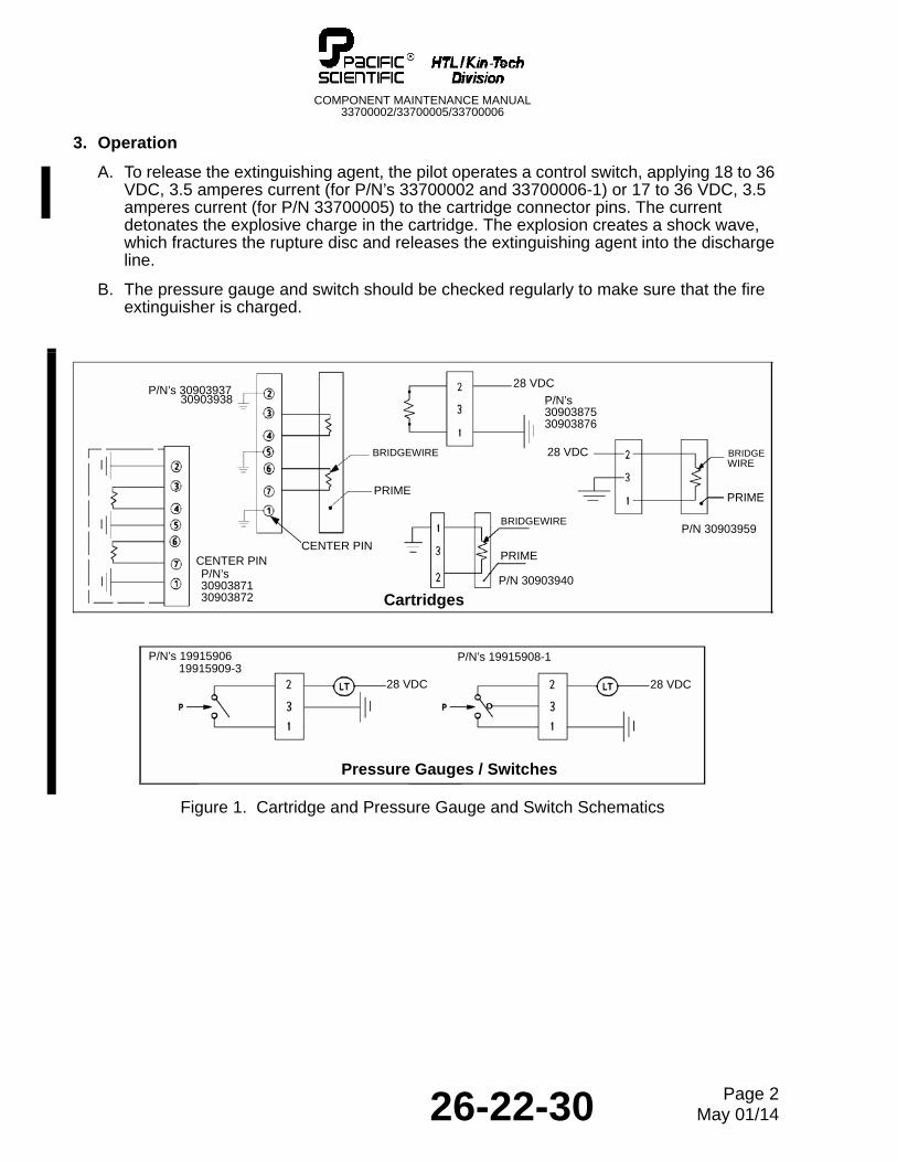
A. To release the extinguishing agent, the pilot operates a control switch, applying 18 to 36 VDC, 3.5 amperes current (for P/N’s 33700002 and 33700006-1) or 17 to 36 VDC, 3.5 amperes current (for P/N 33700005) to the cartridge connector pins. The current detonates the explosive charge in the cartridge. The explosion creates a shock wave, which fractures the rupture disc and releases the extinguishing agent into the discharge line.
B. The pressure gauge and switch should be checked regularly to make sure that the fire extinguisher is charged.
Figure 1. Cartridge and Pressure Gauge and Switch Schematics
Cartridges
Pressure Gauges / Switches
28 VDC
P/N’s3090387530903876
P/N’s3090387130903872
28 VDC
CENTER PIN
28 VDC BRIDGEWIRE
PRIME
P/N’s 30903937
PRIME
BRIDGEWIRE
P/N 30903940
P/N 30903959
30903938
BRIDGEWIRE
PRIME
CENTER PIN
28 VDC
P/N’s 1991590619915909-3
P/N’s 19915908-1
26-22-30 Page 2May 01/14
COMPONENT MAINTENANCE MANUAL33700002/33700005/33700006
Figure 2. Primary Components
4. Technical Properties
A. The technical properties of the fire extinguishers are given in Table 1.
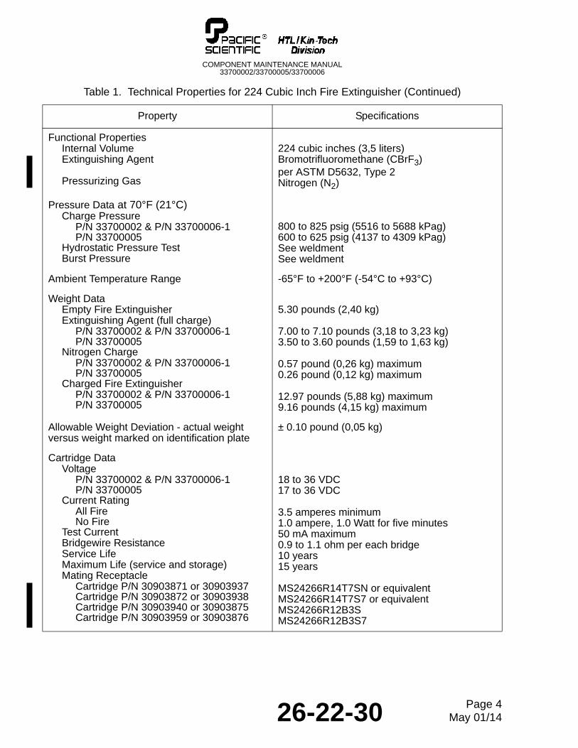
Table 1. Technical Properties for 224 Cubic Inch Fire Extinguisher
Property Specifications
DescriptionManufacturerPart Numbers
Nomenclature
Pacific Scientific, HTL/Kin-Tech DivisionP/N 33700002, P/N 33700005, andP/N 33700006-1
Fire Extinguisher, 224 Cubic Inch Dual Outlet with Switch Gauge
PRESSURE GAUGEAND SWITCH
IDENTIFICATIONPLATE
FILL FITTING ANDSAFETY RELIEF
DISCHARGE
MOUNTINGLUG
CARTRIDGE
CAUTIONPLATE
DATAPLATE
DEVICE
OUTLET
DISCHARGEPORT(RUPTURE DISCWELDED INSIDE)
26-22-30 Page 3May 01/14
COMPONENT MAINTENANCE MANUAL33700002/33700005/33700006
Functional PropertiesInternal VolumeExtinguishing Agent
Pressurizing Gas
224 cubic inches (3,5 liters)Bromotrifluoromethane (CBrF3)per ASTM D5632, Type 2Nitrogen (N2)
Pressure Data at 70°F (21°C)Charge Pressure
P/N 33700002 & P/N 33700006-1P/N 33700005
Hydrostatic Pressure TestBurst Pressure
800 to 825 psig (5516 to 5688 kPag)600 to 625 psig (4137 to 4309 kPag)See weldmentSee weldment
Ambient Temperature Range -65°F to +200°F (-54°C to +93°C)
Weight Data Empty Fire Extinguisher Extinguishing Agent (full charge)
P/N 33700002 & P/N 33700006-1P/N 33700005
Nitrogen ChargeP/N 33700002 & P/N 33700006-1P/N 33700005
Charged Fire Extinguisher P/N 33700002 & P/N 33700006-1P/N 33700005
5.30 pounds (2,40 kg)
7.00 to 7.10 pounds (3,18 to 3,23 kg)3.50 to 3.60 pounds (1,59 to 1,63 kg)
0.57 pound (0,26 kg) maximum0.26 pound (0,12 kg) maximum
12.97 pounds (5,88 kg) maximum9.16 pounds (4,15 kg) maximum
Allowable Weight Deviation - actual weight versus weight marked on identification plate
± 0.10 pound (0,05 kg)
Cartridge DataVoltage
P/N 33700002 & P/N 33700006-1P/N 33700005
Current RatingAll FireNo Fire
Test CurrentBridgewire ResistanceService LifeMaximum Life (service and storage)Mating Receptacle
Cartridge P/N 30903871 or 30903937Cartridge P/N 30903872 or 30903938Cartridge P/N 30903940 or 30903875Cartridge P/N 30903959 or 30903876
18 to 36 VDC17 to 36 VDC
3.5 amperes minimum1.0 ampere, 1.0 Watt for five minutes50 mA maximum0.9 to 1.1 ohm per each bridge10 years15 years
MS24266R14T7SN or equivalentMS24266R14T7S7 or equivalentMS24266R12B3SMS24266R12B3S7
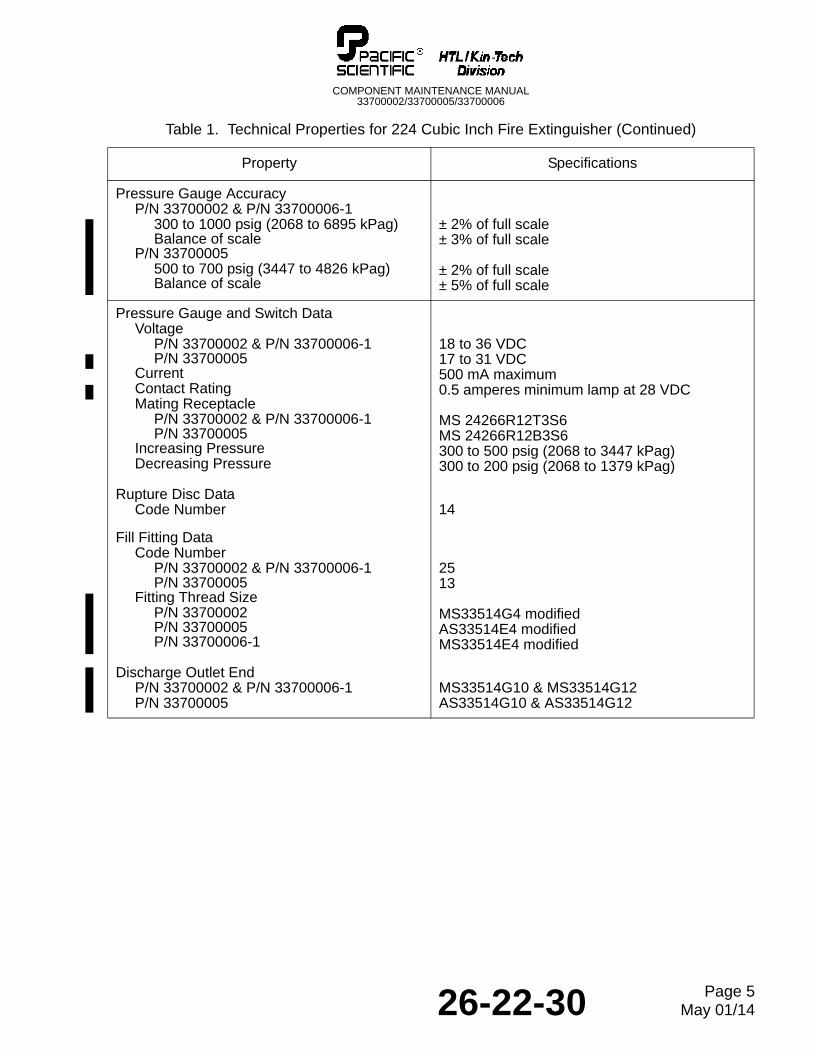
Table 1. Technical Properties for 224 Cubic Inch Fire Extinguisher (Continued)
Property Specifications
26-22-30 Page 4May 01/14
COMPONENT MAINTENANCE MANUAL33700002/33700005/33700006
Pressure Gauge AccuracyP/N 33700002 & P/N 33700006-1
300 to 1000 psig (2068 to 6895 kPag)Balance of scale
P/N 33700005500 to 700 psig (3447 to 4826 kPag)Balance of scale
± 2% of full scale± 3% of full scale
± 2% of full scale± 5% of full scale
Pressure Gauge and Switch DataVoltage
P/N 33700002 & P/N 33700006-1P/N 33700005
Current Contact RatingMating Receptacle
P/N 33700002 & P/N 33700006-1P/N 33700005
Increasing PressureDecreasing Pressure
18 to 36 VDC17 to 31 VDC500 mA maximum0.5 amperes minimum lamp at 28 VDC
MS 24266R12T3S6MS 24266R12B3S6300 to 500 psig (2068 to 3447 kPag)300 to 200 psig (2068 to 1379 kPag)
Rupture Disc DataCode Number 14
Fill Fitting DataCode Number
P/N 33700002 & P/N 33700006-1P/N 33700005
Fitting Thread SizeP/N 33700002P/N 33700005P/N 33700006-1
2513
MS33514G4 modifiedAS33514E4 modifiedMS33514E4 modified
Discharge Outlet EndP/N 33700002 & P/N 33700006-1P/N 33700005
MS33514G10 & MS33514G12AS33514G10 & AS33514G12
Table 1. Technical Properties for 224 Cubic Inch Fire Extinguisher (Continued)
Property Specifications
26-22-30 Page 5May 01/14

COMPONENT MAINTENANCE MANUAL33700002/33700005/33700006
THIS IS A BLANK PAGE
26-22-30 Page 6May 01/14
COMPONENT MAINTENANCE MANUAL33700002/33700005/33700006
TESTING AND FAULT ISOLATION
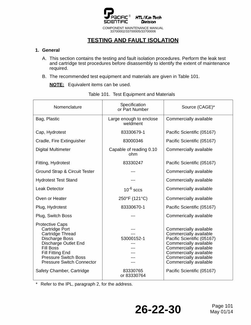
1. General
A. This section contains the testing and fault isolation procedures. Perform the leak test and cartridge test procedures before disassembly to identify the extent of maintenance required.
B. The recommended test equipment and materials are given in Table 101.
NOTE: Equivalent items can be used.
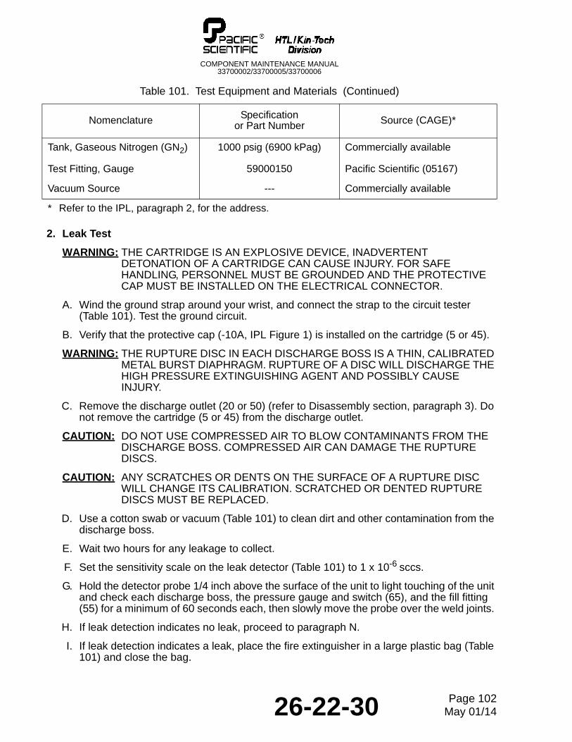
Table 101. Test Equipment and Materials
Nomenclature Specification or Part Number Source (CAGE)*
Bag, Plastic Large enough to enclose weldment
Commercially available
Cap, Hydrotest 83330679-1 Pacific Scientific (05167)
Cradle, Fire Extinguisher 83000346 Pacific Scientific (05167)
Digital Multimeter Capable of reading 0.10 ohm
Commercially available
Fitting, Hydrotest 83330247 Pacific Scientific (05167)
Ground Strap & Circuit Tester --- Commercially available
Hydrotest Test Stand --- Commercially available
Leak Detector 10-6 sccs Commercially available
Oven or Heater 250°F (121°C) Commercially available
Plug, Hydrotest 83330670-1 Pacific Scientific (05167)
Plug, Switch Boss --- Commerically available
Protective CapsCartridge PortCartridge ThreadDischarge BossDischarge Outlet EndFill BossFill Fitting EndPressure Switch BossPressure Switch Connector
------
53000152-1---------------
Commercially availableCommercially availablePacific Scientific (05167)Commercially availableCommercially availableCommercially availableCommercially availableCommercially available
Safety Chamber, Cartridge 83330765 or 83330764
Pacific Scientific (05167)
* Refer to the IPL, paragraph 2, for the address.
26-22-30 Page 101May 01/14
COMPONENT MAINTENANCE MANUAL33700002/33700005/33700006
2. Leak Test
WARNING: THE CARTRIDGE IS AN EXPLOSIVE DEVICE, INADVERTENT DETONATION OF A CARTRIDGE CAN CAUSE INJURY. FOR SAFE HANDLING, PERSONNEL MUST BE GROUNDED AND THE PROTECTIVE CAP MUST BE INSTALLED ON THE ELECTRICAL CONNECTOR.
A. Wind the ground strap around your wrist, and connect the strap to the circuit tester (Table 101). Test the ground circuit.
B. Verify that the protective cap (-10A, IPL Figure 1) is installed on the cartridge (5 or 45).
WARNING: THE RUPTURE DISC IN EACH DISCHARGE BOSS IS A THIN, CALIBRATED METAL BURST DIAPHRAGM. RUPTURE OF A DISC WILL DISCHARGE THE HIGH PRESSURE EXTINGUISHING AGENT AND POSSIBLY CAUSE INJURY.
C. Remove the discharge outlet (20 or 50) (refer to Disassembly section, paragraph 3). Do not remove the cartridge (5 or 45) from the discharge outlet.
CAUTION: DO NOT USE COMPRESSED AIR TO BLOW CONTAMINANTS FROM THE DISCHARGE BOSS. COMPRESSED AIR CAN DAMAGE THE RUPTURE DISCS.
CAUTION: ANY SCRATCHES OR DENTS ON THE SURFACE OF A RUPTURE DISC WILL CHANGE ITS CALIBRATION. SCRATCHED OR DENTED RUPTURE DISCS MUST BE REPLACED.
D. Use a cotton swab or vacuum (Table 101) to clean dirt and other contamination from the discharge boss.
E. Wait two hours for any leakage to collect.
F. Set the sensitivity scale on the leak detector (Table 101) to 1 x 10⁻⁶ sccs.
G. Hold the detector probe 1/4 inch above the surface of the unit to light touching of the unit and check each discharge boss, the pressure gauge and switch (65), and the fill fitting (55) for a minimum of 60 seconds each, then slowly move the probe over the weld joints.
H. If leak detection indicates no leak, proceed to paragraph N.
I. If leak detection indicates a leak, place the fire extinguisher in a large plastic bag (Table 101) and close the bag.
Tank, Gaseous Nitrogen (GN2) 1000 psig (6900 kPag) Commercially available
Test Fitting, Gauge 59000150 Pacific Scientific (05167)
Vacuum Source --- Commercially available
Table 101. Test Equipment and Materials (Continued)
Nomenclature Specification or Part Number Source (CAGE)*
* Refer to the IPL, paragraph 2, for the address.
26-22-30 Page 102May 01/14
COMPONENT MAINTENANCE MANUAL33700002/33700005/33700006
J. Wait 2 hours, then probe the air inside the plastic bag (Table 101) and check each discharge boss, the pressure gauge and switch (65), and the fill fitting (55) for a minimum of 60 seconds each, then slowly move the probe over the weld joints. Record the leakage at each test point.
K. Calculate the leakage rate, as follows:
Li x VLr = T x F
Where: Lr = Leakage rate (sccs)
Li = Detector reading (sccs)V = Volume of plastic bag, less weldment volumeT = Time (in seconds) of weldment inside plastic bagF = Flow rate of leak detector (5 sccs) for Inficon 3000 *
* Refer to equivalent leak detector manual for flow rate.
L. If the leakage rate exceeds 1 x 10⁻⁶ sccs, repair or replace the rupture disc (40), fill fitting (55), pressure gauge and switch (65), or weldment (105), as applicable, and repeat leak test.
M. If the leakage rate is less than 1 x 10⁻⁶ sccs, reinstall the discharge outlet (20 or 50) and the cartridge (5 or 45) (refer to Assembly section, paragraph 6).
N. Install the protective caps (Table 101).
3. Cartridge Test
WARNING: THE CARTRIDGE IS AN EXPLOSIVE DEVICE. INADVERTENT DETONATION OF A CARTRIDGE CAN CAUSE INJURY. FOR SAFE HANDLING, PERSONNEL MUST BE GROUNDED AND THE PROTECTIVE CAP MUST BE INSTALLED ON THE ELECTRICAL CONNECTOR (EXCEPT WHEN SPECIFIED IN THE PROCEDURE).
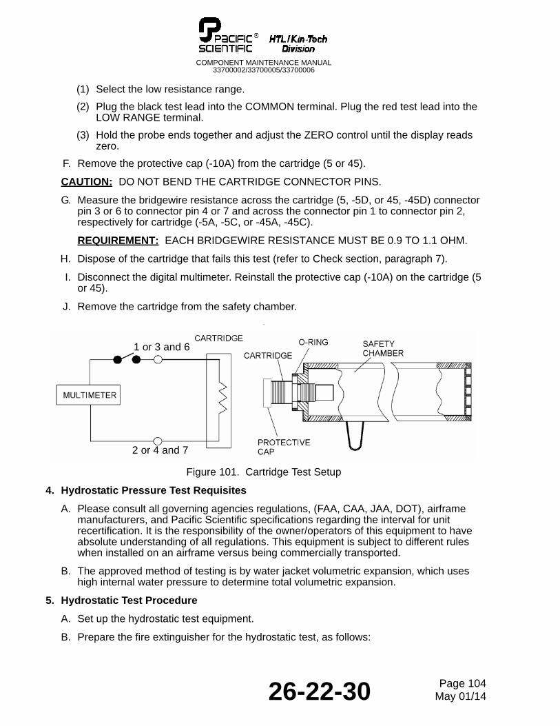
A. Wind the ground strap around your wrist, and connect the strap to the circuit tester (Table 101). Test the ground circuit. Refer to Figure 101.
B. Ground the safety chamber (Table 101).
C. Verify that the protective cap (-10A, IPL Figure 1) is installed on the cartridge (5 or 45).
WARNING: THE CARTRIDGE MUST BE TESTED IN A FIXTURE THAT PROVIDES PROTECTION FOR PERSONNEL. THE SAFETY CHAMBER IS DESIGNED FOR THIS PURPOSE.
D. Thread the cartridge (5 or 45), with the protective cap (-10A) and o-ring (25) installed, into the safety chamber (Table 101).
CAUTION: TEST DEVICES THAT PASS MORE THAN 50 MILLIAMPERES CURRENT CAN AFFECT THE USEFUL LIFE AND RELIABILITY OF THE CARTRIDGE. DO NOT USE A VOLTMETER, FLASHLIGHT BATTERY, CONTINUITY LIGHT, OR SIMILAR DEVICE.
E. Set up the digital multimeter (Table 101), as follows:
26-22-30 Page 103May 01/14
COMPONENT MAINTENANCE MANUAL33700002/33700005/33700006
(1) Select the low resistance range.
(2) Plug the black test lead into the COMMON terminal. Plug the red test lead into the LOW RANGE terminal.
(3) Hold the probe ends together and adjust the ZERO control until the display reads zero.
F. Remove the protective cap (-10A) from the cartridge (5 or 45).
CAUTION: DO NOT BEND THE CARTRIDGE CONNECTOR PINS.
G. Measure the bridgewire resistance across the cartridge (5, -5D, or 45, -45D) connector pin 3 or 6 to connector pin 4 or 7 and across the connector pin 1 to connector pin 2, respectively for cartridge (-5A, -5C, or -45A, -45C).
REQUIREMENT: EACH BRIDGEWIRE RESISTANCE MUST BE 0.9 TO 1.1 OHM.
H. Dispose of the cartridge that fails this test (refer to Check section, paragraph 7).
I. Disconnect the digital multimeter. Reinstall the protective cap (-10A) on the cartridge (5 or 45).
J. Remove the cartridge from the safety chamber.
.
Figure 101. Cartridge Test Setup
4. Hydrostatic Pressure Test Requisites
A. Please consult all governing agencies regulations, (FAA, CAA, JAA, DOT), airframe manufacturers, and Pacific Scientific specifications regarding the interval for unit recertification. It is the responsibility of the owner/operators of this equipment to have absolute understanding of all regulations. This equipment is subject to different rules when installed on an airframe versus being commercially transported.
B. The approved method of testing is by water jacket volumetric expansion, which uses high internal water pressure to determine total volumetric expansion.
5. Hydrostatic Test Procedure
A. Set up the hydrostatic test equipment.
B. Prepare the fire extinguisher for the hydrostatic test, as follows:
1 or 3 and 6
2 or 4 and 7
26-22-30 Page 104May 01/14
COMPONENT MAINTENANCE MANUAL33700002/33700005/33700006
(1) Disassemble the fire extinguisher to remove the cartridges (5 and 45), discharge outlets (20 and 50), rupture discs (40), fill fitting (55), and pressure gauge and switch (65). Refer to the Disassembly section.
(2) Install plugs and caps (Table 101) in the boss locations.
C. Perform hydrostatic test per test stand manufacturer’s instructions.
REQUIREMENT: THE PERMANENT VOLUMETRIC EXPANSION MUST NOT EXCEED 10 PERCENT OF THE TOTAL VOLUMETRIC EXPANSION.
NOTE: If the test pressure cannot be maintained due to a failure of the test apparatus, the test may be repeated at a pressure increase of 10 percent or 100 psig (695 kPag), whichever is the lower value.
D. Repeat the test once if system error is suspected. Replace the weldment if the weldment fails both tests.
E. Remove the caps and plugs (Table 101) from the weldment. Drain the water from the weldment.
F. Heat an oven or heater (Table 101) to 225°F to 250°F (107°C to 121°C). Heat the weldment for one hour or until completely dry.
G. Inspect the weldment (refer to the Check section, paragraph 3).
H. Stamp the hydrostatic test date and DOT identification number next to the pressure stamp on the mounting lug.
6. Pressure Gauge and Switch Functional Test
A. Install the pressure gauge and switch (65, IPL Figure 1) into the gauge test fitting (Table 101).
B. Attach a digital multimeter (Table 101) to connector pins 1 and 2. The digital multimeter should indicate continuity, showing contacts closed.
C. Make sure that the lens on the pressure gauge is clear enough to see the pressure reading clearly.
D. Using the nitrogen source (Table 101), slowly apply pressure (see Table 1) until switch contacts open. The digital multimeter should indicate no continuity, showing contacts open. Check the reading on the gauge, make sure it does not exceed the pressure ranges listed in Table 1.
E. Slowly decrease pressure (see Table 1) until switch contacts close. The digital multimeter should indicate continuity, showing contacts closed, at low pressure switch point. Check the reading on the gauge, make sure it does not go below the pressure ranges listed in Table 1.
F. Remove pressure gauge and switch from the gauge test fitting.
26-22-30 Page 105May 01/14

COMPONENT MAINTENANCE MANUAL33700002/33700005/33700006
THIS IS A BLANK PAGE
26-22-30 Page 106May 01/14
COMPONENT MAINTENANCE MANUAL33700002/33700005/33700006
DISASSEMBLY
1. General
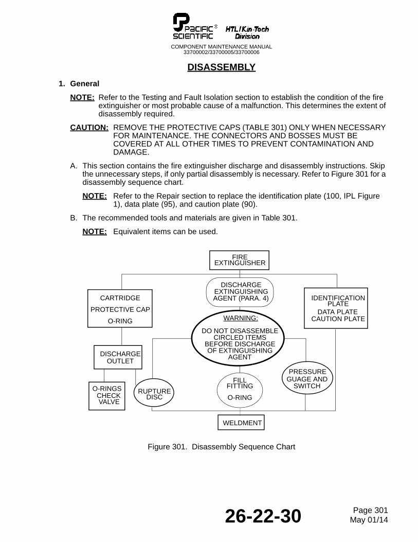
NOTE: Refer to the Testing and Fault Isolation section to establish the condition of the fire extinguisher or most probable cause of a malfunction. This determines the extent of disassembly required.
CAUTION: REMOVE THE PROTECTIVE CAPS (TABLE 301) ONLY WHEN NECESSARY FOR MAINTENANCE. THE CONNECTORS AND BOSSES MUST BE COVERED AT ALL OTHER TIMES TO PREVENT CONTAMINATION AND DAMAGE.
A. This section contains the fire extinguisher discharge and disassembly instructions. Skip the unnecessary steps, if only partial disassembly is necessary. Refer to Figure 301 for a disassembly sequence chart.
NOTE: Refer to the Repair section to replace the identification plate (100, IPL Figure 1), data plate (95), and caution plate (90).
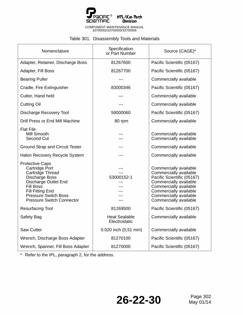
B. The recommended tools and materials are given in Table 301.
NOTE: Equivalent items can be used.
Figure 301. Disassembly Sequence Chart
DATA PLATE
VALVE
FIREEXTINGUISHER
CAUTION PLATE
IDENTIFICATIONPLATE
DISCHARGEOUTLET
PRESSURE
O-RINGSCHECK
WARNING:
DO NOT DISASSEMBLECIRCLED ITEMS
BEFORE DISCHARGEOF EXTINGUISHING
AGENT
DISCHARGEEXTINGUISHINGAGENT (PARA. 4)
FILLFITTING
O-RINGRUPTURE
DISC
GUAGE ANDSWITCH
WELDMENT
CARTRIDGE
PROTECTIVE CAP
O-RING
26-22-30 Page 301May 01/14
COMPONENT MAINTENANCE MANUAL33700002/33700005/33700006
Table 301. Disassembly Tools and Materials
Nomenclature Specification or Part Number Source (CAGE)*
Adapter, Retainer, Discharge Boss 81267600 Pacific Scientific (05167)
Adapter, Fill Boss 81267700 Pacific Scientific (05167)
Bearing Puller --- Commercially available
Cradle, Fire Extinguisher 83000346 Pacific Scientific (05167)
Cutter, Hand held --- Commercially available
Cutting Oil --- Commercially available
Discharge Recovery Tool 59000060 Pacific Scientific (05167)
Drill Press or End Mill Machine 80 rpm Commercially available
Flat FileMill SmoothSecond Cut
------
Commercially availableCommercially available
Ground Strap and Circuit Tester --- Commercially available
Halon Recovery Recycle System --- Commercially available
Protective CapsCartridge PortCartridge ThreadDischarge BossDischarge Outlet EndFill BossFill Fitting EndPressure Switch BossPressure Switch Connector
------
53000152-1---------------
Commercially availableCommercially availablePacific Scientific (05167)Commercially availableCommercially availableCommercially availableCommercially availableCommercially available
Resurfacing Tool 81269500 Pacific Scientific (05167)
Safety Bag Heat Sealable Electrostatic
Commercially available
Saw Cutter 0.020 inch (0,51 mm) Commercially available
Wrench, Discharge Boss Adapter 81270100 Pacific Scientific (05167)
Wrench, Spanner, Fill Boss Adapter 81270000 Pacific Scientific (05167)
* Refer to the IPL, paragraph 2, for the address.
26-22-30 Page 302May 01/14
COMPONENT MAINTENANCE MANUAL33700002/33700005/33700006
CAUTION: DO NOT USE METAL TOOLS TO REMOVE THE O-RINGS. METAL TOOLS CAN SCRATCH THE O-RING GROOVES, CAUSING LEAKAGE AND POSSIBLE CORROSION.
C. Note the procedure and locations of safety wiring to help reassembly. Replace the o-rings at each overhaul.
2. Cartridge
WARNING: THE CARTRIDGE IS AN EXPLOSIVE DEVICE. INADVERTENT DETONATION OF A CARTRIDGE CAN CAUSE INJURY. FOR SAFE HANDLING, PERSONNEL MUST BE GROUNDED AND THE PROTECTIVE CAP MUST BE INSTALLED ON THE ELECTRICAL CONNECTOR.
A. Wind the ground strap around your wrist, and connect the strap to the circuit tester (Table 301). Test the ground circuit.
B. Verify the protective cap (-10A) is installed on the cartridge (5 or 45).
C. Cut the safety wire and remove the cartridge (5 or 45) from the discharge outlet (20 or 50). Remove and discard the o-ring (25).
D. Put the cartridge (5 or 45) in an electrostatic safety bag (Table 301).
3. Discharge Outlet
WARNING: THE RUPTURE DISC IN EACH DISCHARGE BOSS IS A THIN, CALIBRATED METAL BURST DIAPHRAGM. RUPTURE OF A DISC WILL DISCHARGE THE HIGH PRESSURE EXTINGUISHING AGENT AND POSSIBLY CAUSE INJURY.
CAUTION: ANY SCRATCHES OR DENTS ON THE SURFACE OF A RUPTURE DISC WILL CHANGE ITS CALIBRATION. SCRATCHED OR DENTED RUPTURE DISCS MUST BE REPLACED.
A. Remove the cartridge (refer to paragraph 2 above).
B. Cut the safety wire and turn the captive retaining nut on the discharge outlet (20 or 50). Remove the discharge outlet from the discharge boss.
C. Install protective caps (Table 301) on the discharge bosses.
D. Remove and discard the metal gasket and/or the o-ring (35). Do not remove screen (30) unless damaged or clogged.
E. Repeat steps A through D for the remaining cartridge.
WARNING: DO NOT DISASSEMBLE THE FIRE EXTINGUISHER FURTHER UNTIL THE EXTINGUISHING AGENT HAS BEEN DISCHARGED. REFER TO PARAGRAPH 4 BELOW.
4. Discharge Procedure
NOTE: Use this procedure to discharge the extinguishing agent before removing the fill fitting (55, IPL Figure 1), rupture discs (40), or pressure gauge and switch (65).
26-22-30 Page 303May 01/14
COMPONENT MAINTENANCE MANUAL33700002/33700005/33700006
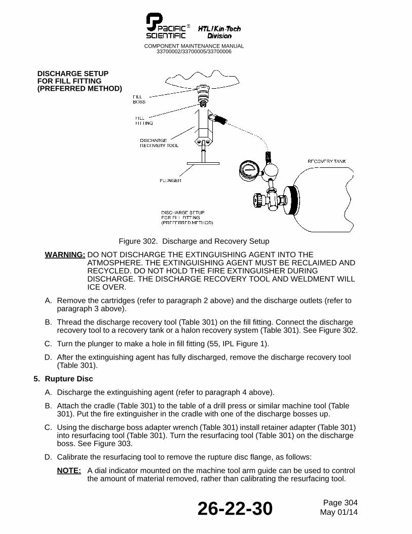
Figure 302. Discharge and Recovery Setup
WARNING: DO NOT DISCHARGE THE EXTINGUISHING AGENT INTO THE ATMOSPHERE. THE EXTINGUISHING AGENT MUST BE RECLAIMED AND RECYCLED. DO NOT HOLD THE FIRE EXTINGUISHER DURING DISCHARGE. THE DISCHARGE RECOVERY TOOL AND WELDMENT WILL ICE OVER.
A. Remove the cartridges (refer to paragraph 2 above) and the discharge outlets (refer to paragraph 3 above).
B. Thread the discharge recovery tool (Table 301) on the fill fitting. Connect the discharge recovery tool to a recovery tank or a halon recovery system (Table 301). See Figure 302.
C. Turn the plunger to make a hole in fill fitting (55, IPL Figure 1).
D. After the extinguishing agent has fully discharged, remove the discharge recovery tool (Table 301).
5. Rupture Disc
A. Discharge the extinguishing agent (refer to paragraph 4 above).
B. Attach the cradle (Table 301) to the table of a drill press or similar machine tool (Table 301). Put the fire extinguisher in the cradle with one of the discharge bosses up.
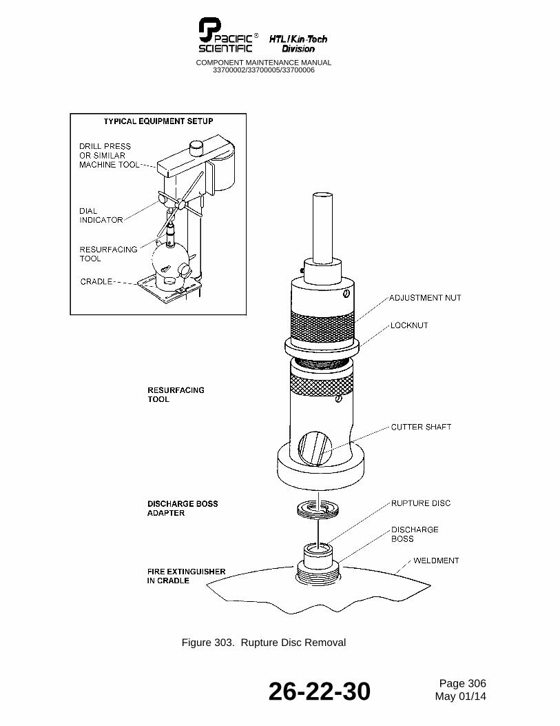
C. Using the discharge boss adapter wrench (Table 301) install retainer adapter (Table 301) into resurfacing tool (Table 301). Turn the resurfacing tool (Table 301) on the discharge boss. See Figure 303.
D. Calibrate the resurfacing tool to remove the rupture disc flange, as follows:
NOTE: A dial indicator mounted on the machine tool arm guide can be used to control the amount of material removed, rather than calibrating the resurfacing tool.
DISCHARGE SETUPFOR FILL FITTING(PREFERRED METHOD)
26-22-30 Page 304May 01/14
COMPONENT MAINTENANCE MANUAL33700002/33700005/33700006
(1) Attach the resurfacing tool to the spindle of the drill press.
(2) Lower the resurfacing tool until its cutting face rests on the rupture disc flange.
(3) Loosen the brass locknut holding the adjustment nut.
(4) Tighten the adjustment nut (left-hand thread) until it touches the stop collar on the cutter shaft.
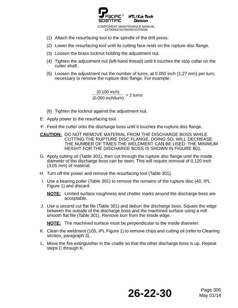
(5) Loosen the adjustment nut the number of turns, at 0.050 inch (1,27 mm) per turn, necessary to remove the rupture disc flange. For example:
(6) Tighten the locknut against the adjustment nut.
E. Apply power to the resurfacing tool.
F. Feed the cutter onto the discharge boss until it touches the rupture disc flange.
CAUTION: DO NOT REMOVE MATERIAL FROM THE DISCHARGE BOSS WHILE CUTTING THE RUPTURE DISC FLANGE. DOING SO, WILL DECREASE THE NUMBER OF TIMES THE WELDMENT CAN BE USED. THE MINIMUM HEIGHT FOR THE DISCHARGE BOSS IS SHOWN IN FIGURE 801.
G. Apply cutting oil (Table 301), then cut through the rupture disc flange until the inside diameter of the discharge boss can be seen. This will require removal of 0.120 inch (3,05 mm) of material.
H. Turn off the power and remove the resurfacing tool (Table 301).
I. Use a bearing puller (Table 301) to remove the remains of the rupture disc (40, IPL Figure 1) and discard.
NOTE: Limited surface roughness and chatter marks around the discharge boss are acceptable.
J. Use a second cut flat file (Table 301) and deburr the discharge boss. Square the edge between the outside of the discharge boss and the machined surface using a mill smooth flat file (Table 301). Remove burr from the inside edge.
NOTE: The machined surface must be perpendicular to the inside diameter.
K. Clean the weldment (105, IPL Figure 1) to remove chips and cutting oil (refer to Cleaning section, paragraph 3).
L. Move the fire extinguisher in the cradle so that the other discharge boss is up. Repeat steps C through K.
= 2 turns(0.050 inch/turn)
(0.100 inch)
26-22-30 Page 305May 01/14
COMPONENT MAINTENANCE MANUAL33700002/33700005/33700006
Figure 303. Rupture Disc Removal
26-22-30 Page 306May 01/14
COMPONENT MAINTENANCE MANUAL33700002/33700005/33700006
6. Fill Fitting
A. Discharge the extinguishing agent (refer to paragraph 4 above).
B. Secure the cradle (Table 301) to the table of a drill press or similar machine tool. Place the fire extinguisher in the cradle with the fill fitting (55, IPL Figure 1) up.
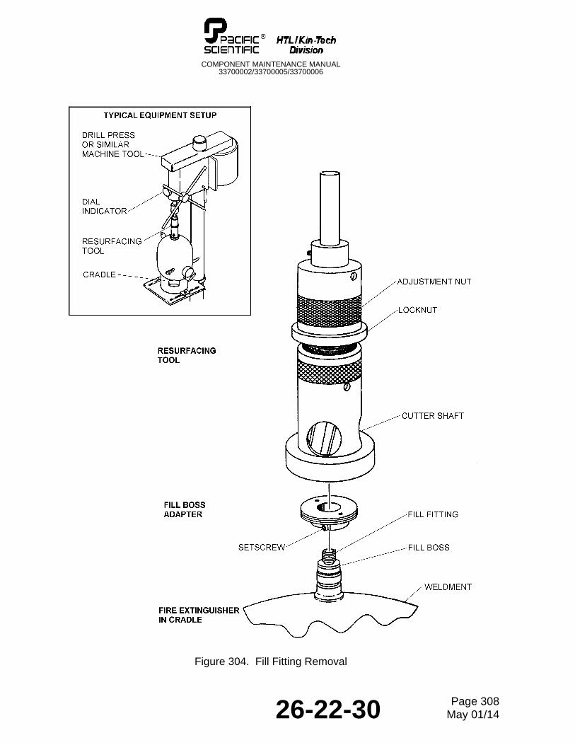
C. Use the fill boss adapter spanner wrench (Table 301) to thread the fill boss adapter (Table 301) into the base of the resurfacing tool (Table 301). See Figure 304.
D. Install the resurfacing tool on the fill fitting. Tighten the adapter setscrew.
E. Calibrate the resurfacing tool to remove the fill fitting flange, as follows:
NOTE: A dial indicator mounted on the machine tool arm guide can be used to control the amount of material removed, rather than calibrating the resurfacing tool.
(1) Attach the resurfacing tool to the spindle of the drill press.
(2) Lower the resurfacing tool until its cutting face rests on the fill fitting flange.
(3) Loosen the brass locknut holding the adjustment nut.
(4) Tighten the adjustment nut (left-hand thread) until it touches the stop collar on the cutter shaft.
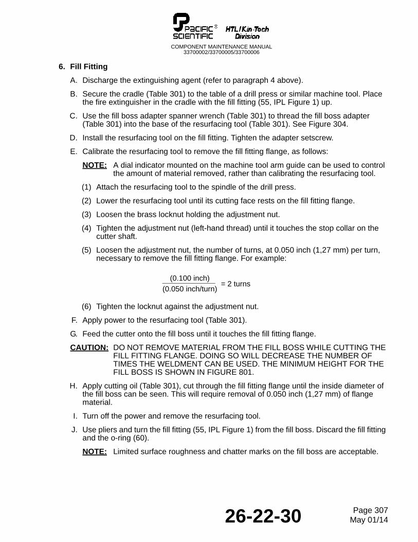
(5) Loosen the adjustment nut, the number of turns, at 0.050 inch (1,27 mm) per turn, necessary to remove the fill fitting flange. For example:
(6) Tighten the locknut against the adjustment nut.
F. Apply power to the resurfacing tool (Table 301).
G. Feed the cutter onto the fill boss until it touches the fill fitting flange.
CAUTION: DO NOT REMOVE MATERIAL FROM THE FILL BOSS WHILE CUTTING THE FILL FITTING FLANGE. DOING SO WILL DECREASE THE NUMBER OF TIMES THE WELDMENT CAN BE USED. THE MINIMUM HEIGHT FOR THE FILL BOSS IS SHOWN IN FIGURE 801.
H. Apply cutting oil (Table 301), cut through the fill fitting flange until the inside diameter of the fill boss can be seen. This will require removal of 0.050 inch (1,27 mm) of flange material.
I. Turn off the power and remove the resurfacing tool.
J. Use pliers and turn the fill fitting (55, IPL Figure 1) from the fill boss. Discard the fill fitting and the o-ring (60).
NOTE: Limited surface roughness and chatter marks on the fill boss are acceptable.
= 2 turns(0.050 inch/turn)
(0.100 inch)
26-22-30 Page 307May 01/14
COMPONENT MAINTENANCE MANUAL33700002/33700005/33700006
Figure 304. Fill Fitting Removal
26-22-30 Page 308May 01/14
COMPONENT MAINTENANCE MANUAL33700002/33700005/33700006
K. Use a second cut flat file (Table 301) and deburr the fill boss. Square the edge between the outside of the fill boss and the machined surface using a mill smooth flat file (Table 301). Remove burr from the inside edge.
NOTE: The machined surface must be perpendicular to the inside diameter.
L. Clean the weldment (105) to remove the chips and cutting oil (refer to Cleaning section, paragraph 3).
7. Pressure Gauge and Switch
A. Discharge the extinguishing agent (refer to paragraph 4 above).
B. Attach the cradle (Table 301) to a work surface.
C. Put the weldment (105, IPL Figure 1) in the cradle.
D. Remove the screw (85) and the gauge guard (80) from the switch boss.
E. Loosen the nut and installed pressure gauge and switch (65) from the switch boss.
F. Remove o-ring (75) and retainer (70).
G. Turn the pressure gauge and switch (65) from the switch boss. Check the pressure switch using the Testing and Fault Isolation procedure, paragraph 6. If the pressure gauge and switch is acceptable, install after successful completion of hydrostatic test of the weldment.
H. Clean the weldment (105) (refer to Cleaning section, paragraph 3).
26-22-30 Page 309May 01/14

COMPONENT MAINTENANCE MANUAL33700002/33700005/33700006
THIS IS A BLANK PAGE
26-22-30 Page 310May 01/14
COMPONENT MAINTENANCE MANUAL33700002/33700005/33700006
CLEANING
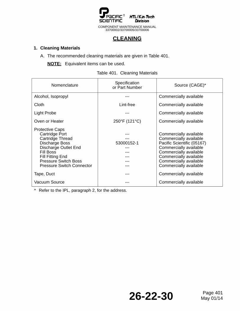
1. Cleaning Materials
A. The recommended cleaning materials are given in Table 401.
NOTE: Equivalent items can be used.
Table 401. Cleaning Materials
Nomenclature Specification or Part Number Source (CAGE)*
Alcohol, Isopropyl --- Commercially available
Cloth Lint-free Commercially available
Light Probe --- Commercially available
Oven or Heater 250°F (121°C) Commercially available
Protective CapsCartridge PortCartridge ThreadDischarge BossDischarge Outlet EndFill BossFill Fitting EndPressure Switch BossPressure Switch Connector
------
53000152-1---------------
Commercially availableCommercially availablePacific Scientific (05167)Commercially availableCommercially availableCommercially availableCommercially availableCommercially available
Tape, Duct --- Commercially available
Vacuum Source --- Commercially available
* Refer to the IPL, paragraph 2, for the address.
26-22-30 Page 401May 01/14
COMPONENT MAINTENANCE MANUAL33700002/33700005/33700006
2. Metal Parts
WARNING: INCORRECT HANDLING OF A CHARGED FIRE EXTINGUISHER CAN CAUSE ACCIDENTAL DISCHARGE OF THE EXTINGUISHING AGENT AND POSSIBLE INJURY. DO NOT APPLY PRESSURE TO, OR INSERT ANYTHING INTO, THE DISCHARGE BOSSES.
WARNING: THE CLEANING SOLVENT IS FLAMMABLE AND AN IRRITANT TO THE EYES AND NOSE. USE SOLVENT ONLY IN A WELL VENTILATED AREA AWAY FROM OPEN FLAMES. IF EYES BECOME IRRITATED, FLUSH WITH WATER.
CAUTION: ANY SCRATCHES OR DENTS ON THE SURFACE OF A RUPTURE DISC WILL CHANGE ITS CALIBRATION. SCRATCHED OR DENTED RUPTURE DISCS MUST BE REPLACED.
A. Clean all the metal parts, excluding the rupture discs (40, IPL Figure 1), with lint-free cloths and isopropyl alcohol (Table 401). Use a cotton swab or vacuum (Table 401) to clean the rupture discs.
B. Dry all parts thoroughly with clean, lint-free cloths.
3. Weldment
A. Clean the inside of the weldment (105, IPL Figure 1) after removing the fill fitting (55), rupture discs (40), and pressure gauge and switch (65), as follows:
(1) Pour 1/4 to 1/2 cup of isopropyl alcohol (Table 401) into the weldment.
(2) Shake the weldment in a circular movement, and drain the alcohol into a disposal container.
(3) Repeat the procedure until no further metal chips or filings are evident in the alcohol. Use a light probe and inspect the inside of the weldment.
(4) Heat an oven or heater (Table 401) 225°F to 250°F (107°C to 121°C). Heat the weldment for one hour or until completely dry.
B. Vapor hone unwanted discoloration from the outside of the weldment, as follows:
(1) Install the protective caps (Table 401).
(2) Cover the data plates with duct tape (Table 401).
(3) Vapor hone the weldment (wet or dry glass bead). Do not vapor hone the protected threads on the fill, discharge, and switch bosses.
(4) Remove the duct tape and protective caps, then clean the weldment completely (refer to paragraph 3.A above).
26-22-30 Page 402May 01/14
COMPONENT MAINTENANCE MANUAL33700002/33700005/33700006
CHECK
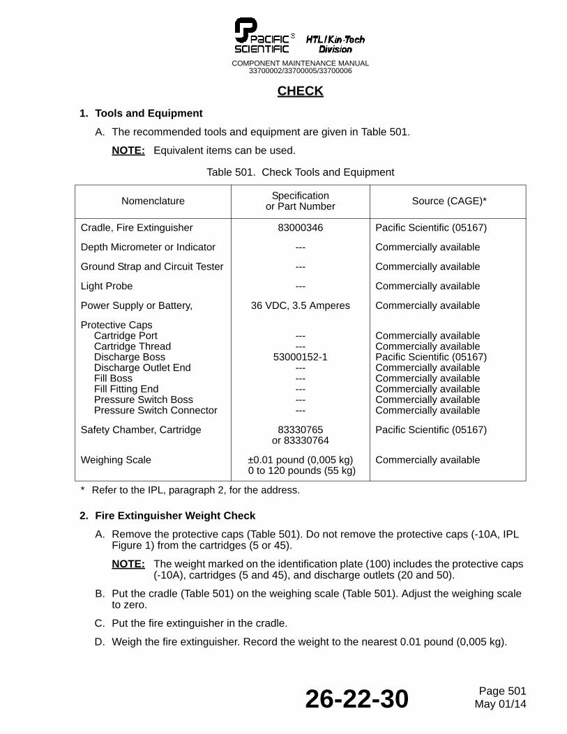
1. Tools and Equipment
A. The recommended tools and equipment are given in Table 501.
NOTE: Equivalent items can be used.
2. Fire Extinguisher Weight Check
A. Remove the protective caps (Table 501). Do not remove the protective caps (-10A, IPL Figure 1) from the cartridges (5 or 45).
NOTE: The weight marked on the identification plate (100) includes the protective caps (-10A), cartridges (5 and 45), and discharge outlets (20 and 50).
B. Put the cradle (Table 501) on the weighing scale (Table 501). Adjust the weighing scale to zero.
C. Put the fire extinguisher in the cradle.
D. Weigh the fire extinguisher. Record the weight to the nearest 0.01 pound (0,005 kg).
Table 501. Check Tools and Equipment
Nomenclature Specification or Part Number Source (CAGE)*
Cradle, Fire Extinguisher 83000346 Pacific Scientific (05167)
Depth Micrometer or Indicator --- Commercially available
Ground Strap and Circuit Tester --- Commercially available
Light Probe --- Commercially available
Power Supply or Battery, 36 VDC, 3.5 Amperes Commercially available
Protective CapsCartridge PortCartridge ThreadDischarge BossDischarge Outlet EndFill BossFill Fitting EndPressure Switch BossPressure Switch Connector
------
53000152-1---------------
Commercially availableCommercially availablePacific Scientific (05167)Commercially availableCommercially availableCommercially availableCommercially availableCommercially available
Safety Chamber, Cartridge 83330765 or 83330764
Pacific Scientific (05167)
Weighing Scale ±0.01 pound (0,005 kg) 0 to 120 pounds (55 kg)
Commercially available
* Refer to the IPL, paragraph 2, for the address.
26-22-30 Page 501May 01/14
COMPONENT MAINTENANCE MANUAL33700002/33700005/33700006
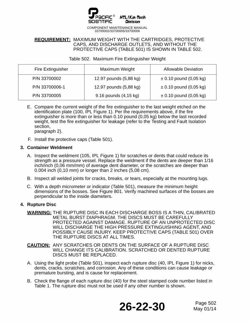
REQUIREMENT: MAXIMUM WEIGHT WITH THE CARTRIDGES, PROTECTIVE CAPS, AND DISCHARGE OUTLETS, AND WITHOUT THE PROTECTIVE CAPS (TABLE 501) IS SHOWN IN TABLE 502.
E. Compare the current weight of the fire extinguisher to the last weight etched on the identification plate (100, IPL Figure 1). Per the requirements above, if the fire extinguisher is more than or less than 0.10 pound (0,05 kg) below the last recorded weight, test the fire extinguisher for leakage (refer to the Testing and Fault Isolation section, paragraph 2).
F. Install the protective caps (Table 501).
3. Container Weldment
A. Inspect the weldment (105, IPL Figure 1) for scratches or dents that could reduce its strength as a pressure vessel. Replace the weldment if the dents are deeper than 1/16 inch/inch (0,06 mm/mm) of average dent diameter, or the scratches are deeper than 0.004 inch (0,10 mm) or longer than 2 inches (5,08 cm).
B. Inspect all welded joints for cracks, breaks, or tears, especially at the mounting lugs.
C. With a depth micrometer or indicator (Table 501), measure the minimum height dimensions of the bosses. See Figure 801. Verify machined surfaces of the bosses are perpendicular to the inside diameters.
4. Rupture Disc
WARNING: THE RUPTURE DISC IN EACH DISCHARGE BOSS IS A THIN, CALIBRATED METAL BURST DIAPHRAGM. THE DISCS MUST BE CAREFULLY PROTECTED AGAINST DAMAGE. RUPTURE OF AN UNPROTECTED DISC WILL DISCHARGE THE HIGH PRESSURE EXTINGUISHING AGENT, AND POSSIBLY CAUSE INJURY. KEEP PROTECTIVE CAPS (TABLE 501) OVER THE RUPTURE DISCS AT ALL TIMES.
CAUTION: ANY SCRATCHES OR DENTS ON THE SURFACE OF A RUPTURE DISC WILL CHANGE ITS CALIBRATION. SCRATCHED OR DENTED RUPTURE DISCS MUST BE REPLACED.
A. Using the light probe (Table 501), inspect each rupture disc (40, IPL Figure 1) for nicks, dents, cracks, scratches, and corrosion. Any of these conditions can cause leakage or premature bursting, and is cause for replacement.
B. Check the flange of each rupture disc (40) for the steel stamped code number listed in Table 1. The rupture disc must not be used if any other number is shown.
Table 502. Maximum Fire Extinguisher Weight
Fire Extinguisher Maximum Weight Allowable Deviation
P/N 33700002 12.97 pounds (5,88 kg) ± 0.10 pound (0,05 kg)
P/N 33700006-1 12.97 pounds (5,88 kg) ± 0.10 pound (0,05 kg)
P/N 33700005 9.16 pounds (4,15 kg) ± 0.10 pound (0,05 kg)
26-22-30 Page 502May 01/14
COMPONENT MAINTENANCE MANUAL33700002/33700005/33700006
5. Discharge Outlet
A. Using the light probe (Table 501), inspect each discharge outlet (20 and 50, IPL Figure 1) for cracks, corrosion, crossed threads, stripped threads, chafing, scoring, and any other damage that might decrease operation. Dark stains on inside surfaces, caused by previous firing of the cartridges, are acceptable. Replace discharge outlets that are not acceptable.
6. Fill Fitting
A. Check the fill fitting (55, IPL Figure 1) for the steel stamped code number listed in Table 1. The fill fitting must not be used if any other number is shown.
7. Cartridge
WARNING: THE CARTRIDGE IS AN EXPLOSIVE DEVICE. INADVERTENT DETONATION OF A CARTRIDGE CAN CAUSE INJURY. FOR SAFE HANDLING, PERSONNEL MUST BE GROUNDED AND THE PROTECTIVE CAP MUST BE INSTALLED ON THE ELECTRICAL CONNECTOR (EXCEPT WHEN SPECIFIED IN THE PROCEDURE).
A. Wind the ground strap around your wrist, and connect the strap to the circuit tester (Table 501). Test the ground circuit.
B. Remove the protective cap (-10A, IPL Figure 1) and inspect the cartridge (5 or 45) electrical connector pins for security and corrosion. If the pins are loose or corroded, reinstall the protective cap (-10A) and dispose of the cartridge (5 or 45) (refer to step D, below).
C. Check the service date (month/year) etched on the wrench flats of the cartridge (5 or 45). Dispose of the cartridges (as specified in step D, below) if its service life or combined life (service and storage) exceeds the limits.
D. Repeat steps B and C for the remaining cartridge.
REQUIREMENT: THE CARTRIDGE MARKED WITH 10 YR ON A WRENCH FLAT, HAS A MAXIMUM INSTALLED SERVICE LIFE OF 10 YEARS AND A COMBINED SERVICE/STORAGE LIFE OF 15 YEARS.
E. Cartridge Disposal
WARNING: THE CARTRIDGE MUST BE DETONATED IN A FIXTURE THAT GIVES PROTECTION FOR PERSONNEL. THE SAFETY CHAMBER IS DESIGNED FOR THIS PURPOSE.
(1) Ground the safety chamber (Table 501). The ground strap must be connected and grounded.
(2) Make sure that the protective cap (-10A) is installed in the cartridge (5 or 45).
(3) Cut the safety wire and remove the cartridge (5 or 45) from the discharge outlet (20 or 50). Leave the o-ring (25) installed on the cartridge.
(4) Thread the cartridge (5 or 45) with the protective cap (-10A) installed, tightly into the safety chamber (Table 501). See Figure 501.
26-22-30 Page 503May 01/14
COMPONENT MAINTENANCE MANUAL33700002/33700005/33700006
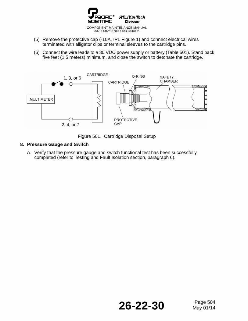
(5) Remove the protective cap (-10A, IPL Figure 1) and connect electrical wires terminated with alligator clips or terminal sleeves to the cartridge pins.
(6) Connect the wire leads to a 30 VDC power supply or battery (Table 501). Stand back five feet (1.5 meters) minimum, and close the switch to detonate the cartridge.
Figure 501. Cartridge Disposal Setup
8. Pressure Gauge and Switch
A. Verify that the pressure gauge and switch functional test has been successfully completed (refer to Testing and Fault Isolation section, paragraph 6).
2, 4, or 7
1, 3, or 6
26-22-30 Page 504May 01/14
COMPONENT MAINTENANCE MANUAL33700002/33700005/33700006
REPAIR
1. General
A. The repair instructions are limited to replacement of a damaged caution plate, data plate, and identification plate (90, 95, and 100, IPL Figure 1). Refer to the Disassembly and Assembly sections to replace all other components.
B. The recommended tools and materials are given in Table 601.
NOTE: Equivalent items can be used.
C. Repairs that require welding, except those covered in the Assembly section of this manual, are not permitted unless authorized in writing by Pacific Scientific Company.
D. After Pacific Scientific Company approval, repairs that require welding must be made in accordance with the latest FAA directives and under the supervision of a certified FAA mechanic with an airframe rating. If any doubt exists regarding penetration of the weld, inspect the welded part in accordance with MIL-STD-453.
2. Replacement of Bonded Plates
A. Copy the information from the old identification plate (100, IPL Figure 1) to the new identification plate (100).
B. Use 240 grit sandpaper (Table 601) to roughen the face of the old plates (90, 95, and 100) and the back of the new plates (90, 95, and 100).
C. Clean the plates using isopropyl alcohol (Table 601). Let dry.
D. Apply activator to the plates. Within two hours, apply approximately 0.6 gram of adhesive to the new plate.
E. Press the new plates (90, 95, and 100) on the old plates (90, 95, and 100) with a twisting motion to aid intermixing.
F. Remove excess adhesive from the new plates (90, 95, and 100) and area around them with alcohol after the new plates (90, 95, and 100) have fixtured cured, but before excess adhesive has dried.
Table 601. Repair Tools and Materials
Nomenclature Specificationor Part Number Source
Adhesive --- Commercially available
Activator --- Commercially available
Alcohol, Isopropyl --- Commercially available
Nycote 7-11 --- Commercially available
Sandpaper 240 grit Commercially available
26-22-30 Page 601May 01/14

COMPONENT MAINTENANCE MANUAL33700002/33700005/33700006
THIS IS A BLANK PAGE
26-22-30 Page 602May 01/14
COMPONENT MAINTENANCE MANUAL33700002/33700005/33700006
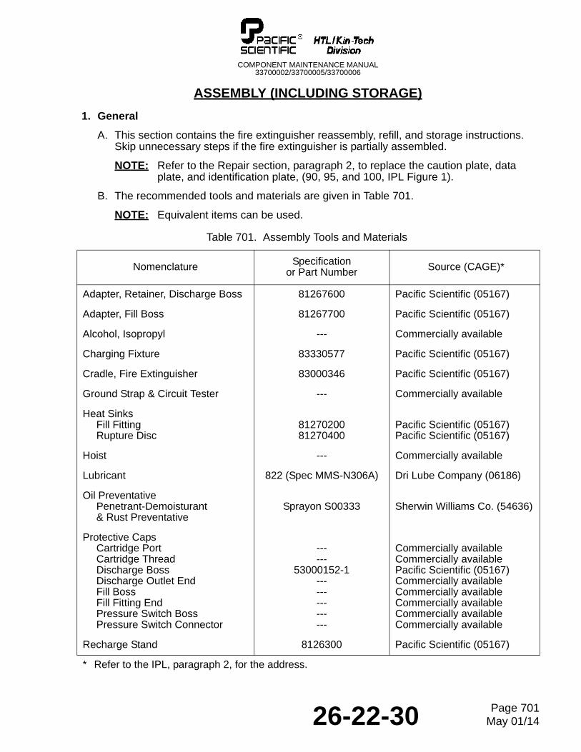
ASSEMBLY (INCLUDING STORAGE)
1. General
A. This section contains the fire extinguisher reassembly, refill, and storage instructions. Skip unnecessary steps if the fire extinguisher is partially assembled.
NOTE: Refer to the Repair section, paragraph 2, to replace the caution plate, data plate, and identification plate, (90, 95, and 100, IPL Figure 1).
B. The recommended tools and materials are given in Table 701.
NOTE: Equivalent items can be used.
Table 701. Assembly Tools and Materials
Nomenclature Specification or Part Number Source (CAGE)*
Adapter, Retainer, Discharge Boss 81267600 Pacific Scientific (05167)
Adapter, Fill Boss 81267700 Pacific Scientific (05167)
Alcohol, Isopropyl --- Commercially available
Charging Fixture 83330577 Pacific Scientific (05167)
Cradle, Fire Extinguisher 83000346 Pacific Scientific (05167)
Ground Strap & Circuit Tester --- Commercially available
Heat SinksFill FittingRupture Disc
8127020081270400
Pacific Scientific (05167)Pacific Scientific (05167)
Hoist --- Commercially available
Lubricant 822 (Spec MMS-N306A) Dri Lube Company (06186)
Oil PreventativePenetrant-Demoisturant& Rust Preventative
Sprayon S00333 Sherwin Williams Co. (54636)
Protective CapsCartridge PortCartridge ThreadDischarge BossDischarge Outlet EndFill BossFill Fitting EndPressure Switch BossPressure Switch Connector
------
53000152-1---------------
Commercially availableCommercially availablePacific Scientific (05167)Commercially availableCommercially availableCommercially availableCommercially availableCommercially available
Recharge Stand 8126300 Pacific Scientific (05167)
* Refer to the IPL, paragraph 2, for the address.
26-22-30 Page 701May 01/14
COMPONENT MAINTENANCE MANUAL33700002/33700005/33700006
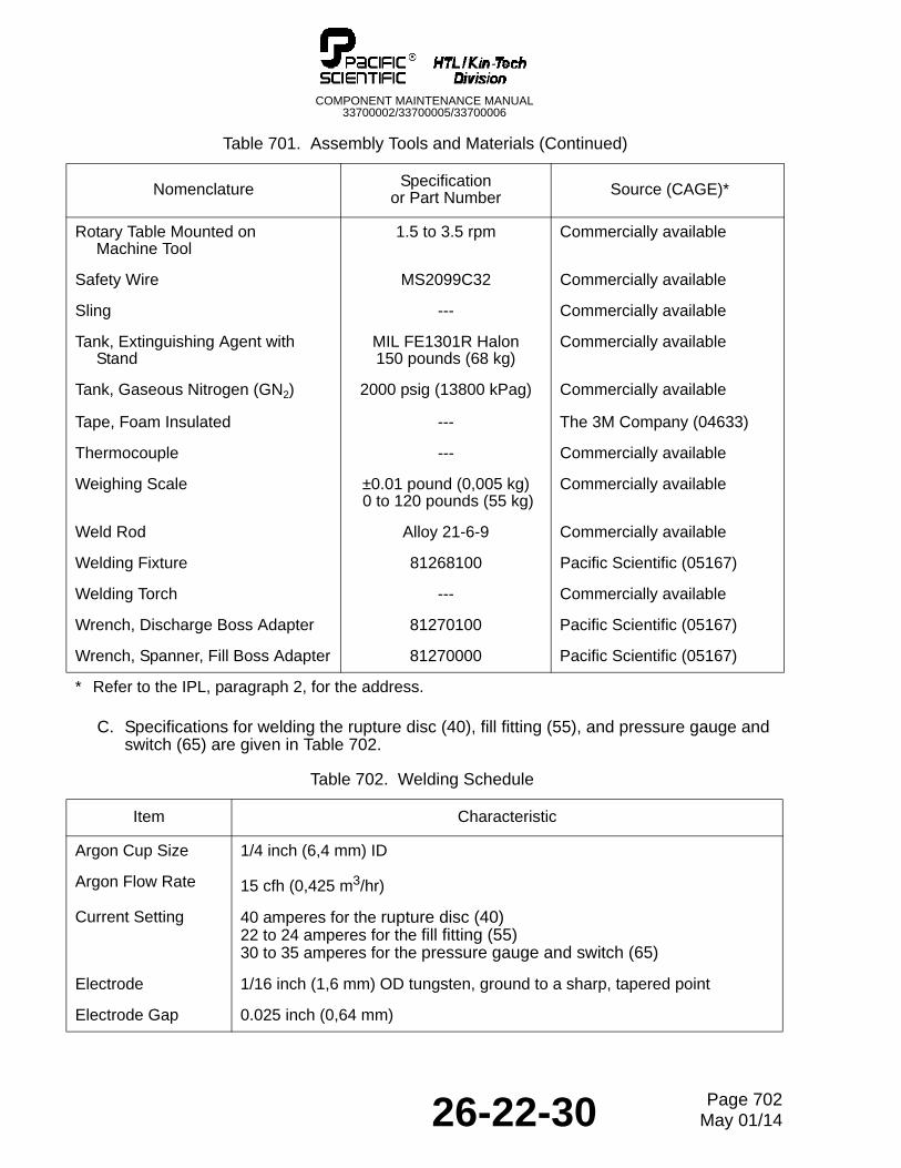
C. Specifications for welding the rupture disc (40), fill fitting (55), and pressure gauge and switch (65) are given in Table 702.
Rotary Table Mounted onMachine Tool
1.5 to 3.5 rpm Commercially available
Safety Wire MS2099C32 Commercially available
Sling --- Commercially available
Tank, Extinguishing Agent withStand
MIL FE1301R Halon150 pounds (68 kg)
Commercially available
Tank, Gaseous Nitrogen (GN2) 2000 psig (13800 kPag) Commercially available
Tape, Foam Insulated --- The 3M Company (04633)
Thermocouple --- Commercially available
Weighing Scale ±0.01 pound (0,005 kg) 0 to 120 pounds (55 kg)
Commercially available
Weld Rod Alloy 21-6-9 Commercially available
Welding Fixture 81268100 Pacific Scientific (05167)
Welding Torch --- Commercially available
Wrench, Discharge Boss Adapter 81270100 Pacific Scientific (05167)
Wrench, Spanner, Fill Boss Adapter 81270000 Pacific Scientific (05167)
Table 702. Welding Schedule
Item Characteristic
Argon Cup Size 1/4 inch (6,4 mm) ID
Argon Flow Rate 15 cfh (0,425 m3/hr)
Current Setting 40 amperes for the rupture disc (40) 22 to 24 amperes for the fill fitting (55)30 to 35 amperes for the pressure gauge and switch (65)
Electrode 1/16 inch (1,6 mm) OD tungsten, ground to a sharp, tapered point
Electrode Gap 0.025 inch (0,64 mm)
Table 701. Assembly Tools and Materials (Continued)
Nomenclature Specification or Part Number Source (CAGE)*
* Refer to the IPL, paragraph 2, for the address.
26-22-30 Page 702May 01/14
COMPONENT MAINTENANCE MANUAL33700002/33700005/33700006
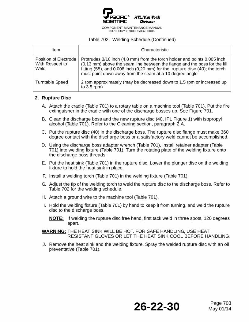
2. Rupture Disc
A. Attach the cradle (Table 701) to a rotary table on a machine tool (Table 701). Put the fire extinguisher in the cradle with one of the discharge bosses up. See Figure 701.
B. Clean the discharge boss and the new rupture disc (40, IPL Figure 1) with isopropyl alcohol (Table 701). Refer to the Cleaning section, paragraph 2.A.
C. Put the rupture disc (40) in the discharge boss. The rupture disc flange must make 360 degree contact with the discharge boss or a satisfactory weld cannot be accomplished.
D. Using the discharge boss adapter wrench (Table 701), install retainer adapter (Table 701) into welding fixture (Table 701). Turn the rotating plate of the welding fixture onto the discharge boss threads.
E. Put the heat sink (Table 701) in the rupture disc. Lower the plunger disc on the welding fixture to hold the heat sink in place.
F. Install a welding torch (Table 701) in the welding fixture (Table 701).
G. Adjust the tip of the welding torch to weld the rupture disc to the discharge boss. Refer to Table 702 for the welding schedule.
H. Attach a ground wire to the machine tool (Table 701).
I. Hold the welding fixture (Table 701) by hand to keep it from turning, and weld the rupture disc to the discharge boss.
NOTE: If welding the rupture disc free hand, first tack weld in three spots, 120 degrees apart.
WARNING: THE HEAT SINK WILL BE HOT. FOR SAFE HANDLING, USE HEAT RESISTANT GLOVES OR LET THE HEAT SINK COOL BEFORE HANDLING.
J. Remove the heat sink and the welding fixture. Spray the welded rupture disc with an oil preventative (Table 701).
Position of ElectrodeWith Respect to Weld
Protrudes 3/16 inch (4,8 mm) from the torch holder and points 0.005 inch (0,13 mm) above the seam line between the flange and the boss for the fill fitting (55), and 0.008 inch (0,20 mm) for the rupture disc (40); the torch must point down away from the seam at a 10 degree angle
Turntable Speed 2 rpm approximately (may be decreased down to 1.5 rpm or increased up to 3.5 rpm)
Table 702. Welding Schedule (Continued)
Item Characteristic
26-22-30 Page 703May 01/14
COMPONENT MAINTENANCE MANUAL33700002/33700005/33700006
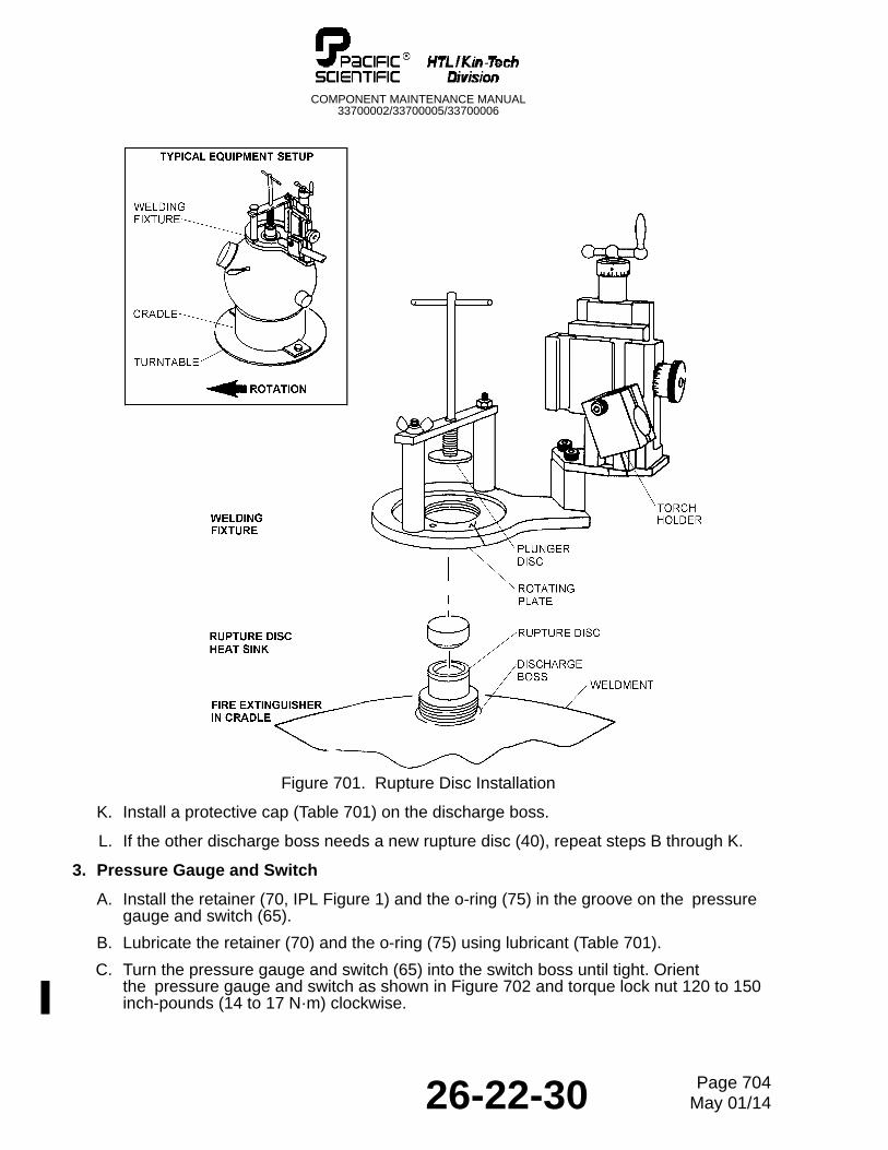
Figure 701. Rupture Disc Installation
K. Install a protective cap (Table 701) on the discharge boss.
L. If the other discharge boss needs a new rupture disc (40), repeat steps B through K.
3. Pressure Gauge and Switch
A. Install the retainer (70, IPL Figure 1) and the o-ring (75) in the groove on the pressure gauge and switch (65).
B. Lubricate the retainer (70) and the o-ring (75) using lubricant (Table 701).
C. Turn the pressure gauge and switch (65) into the switch boss until tight. Orient the pressure gauge and switch as shown in Figure 702 and torque lock nut 120 to 150 inch-pounds (14 to 17 N·m) clockwise.
26-22-30 Page 704May 01/14
COMPONENT MAINTENANCE MANUAL33700002/33700005/33700006
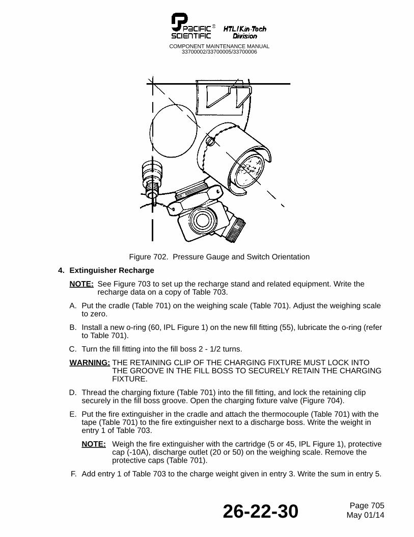
Figure 702. Pressure Gauge and Switch Orientation
4. Extinguisher Recharge
NOTE: See Figure 703 to set up the recharge stand and related equipment. Write the recharge data on a copy of Table 703.
A. Put the cradle (Table 701) on the weighing scale (Table 701). Adjust the weighing scale to zero.
B. Install a new o-ring (60, IPL Figure 1) on the new fill fitting (55), lubricate the o-ring (refer to Table 701).
C. Turn the fill fitting into the fill boss 2 - 1/2 turns.
WARNING: THE RETAINING CLIP OF THE CHARGING FIXTURE MUST LOCK INTO THE GROOVE IN THE FILL BOSS TO SECURELY RETAIN THE CHARGING FIXTURE.
D. Thread the charging fixture (Table 701) into the fill fitting, and lock the retaining clip securely in the fill boss groove. Open the charging fixture valve (Figure 704).
E. Put the fire extinguisher in the cradle and attach the thermocouple (Table 701) with the tape (Table 701) to the fire extinguisher next to a discharge boss. Write the weight in entry 1 of Table 703.
NOTE: Weigh the fire extinguisher with the cartridge (5 or 45, IPL Figure 1), protective cap (-10A), discharge outlet (20 or 50) on the weighing scale. Remove the protective caps (Table 701).
F. Add entry 1 of Table 703 to the charge weight given in entry 3. Write the sum in entry 5.
26-22-30 Page 705May 01/14
COMPONENT MAINTENANCE MANUAL33700002/33700005/33700006
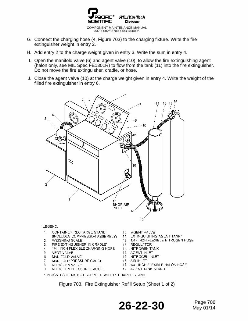
G. Connect the charging hose (4, Figure 703) to the charging fixture. Write the fire extinguisher weight in entry 2.
H. Add entry 2 to the charge weight given in entry 3. Write the sum in entry 4.
I. Open the manifold valve (6) and agent valve (10), to allow the fire extinguishing agent (halon only, see MIL Spec FE1301R) to flow from the tank (11) into the fire extinguisher. Do not move the fire extinguisher, cradle, or hose.
J. Close the agent valve (10) at the charge weight given in entry 4. Write the weight of the filled fire extinguisher in entry 6.
Figure 703. Fire Extinguisher Refill Setup (Sheet 1 of 2)
26-22-30 Page 706May 01/14
COMPONENT MAINTENANCE MANUAL33700002/33700005/33700006
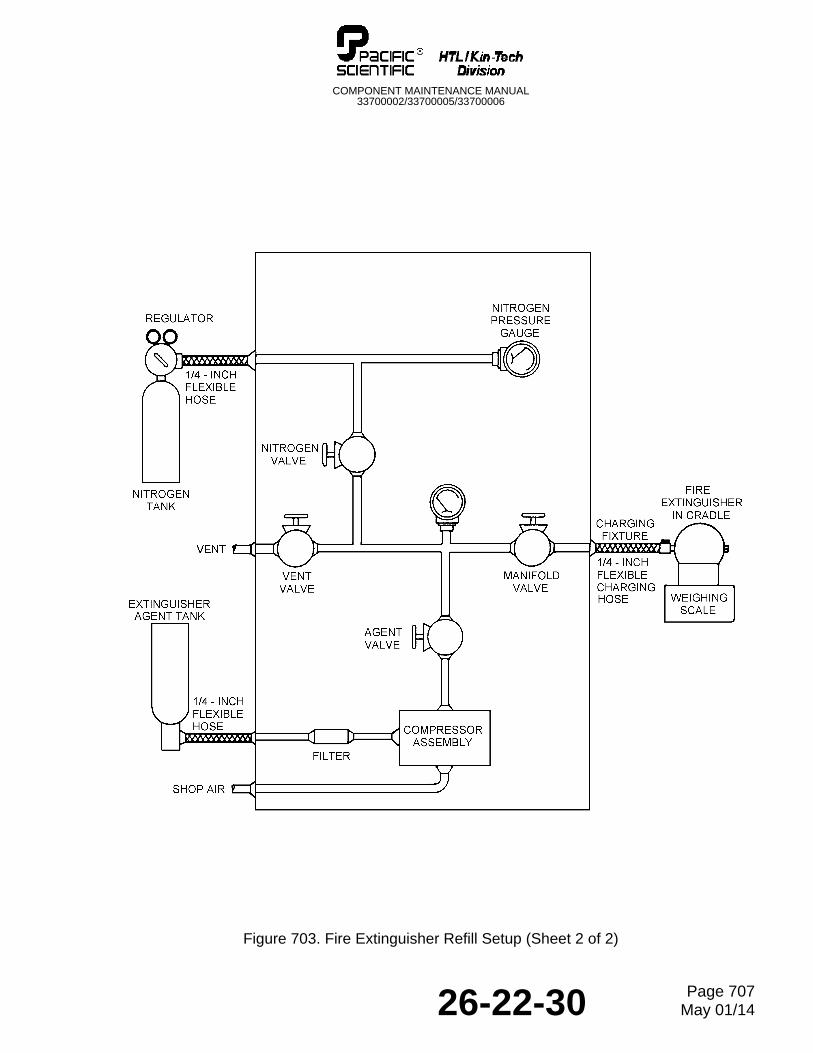
Figure 703. Fire Extinguisher Refill Setup (Sheet 2 of 2)
26-22-30 Page 707May 01/14
COMPONENT MAINTENANCE MANUAL33700002/33700005/33700006
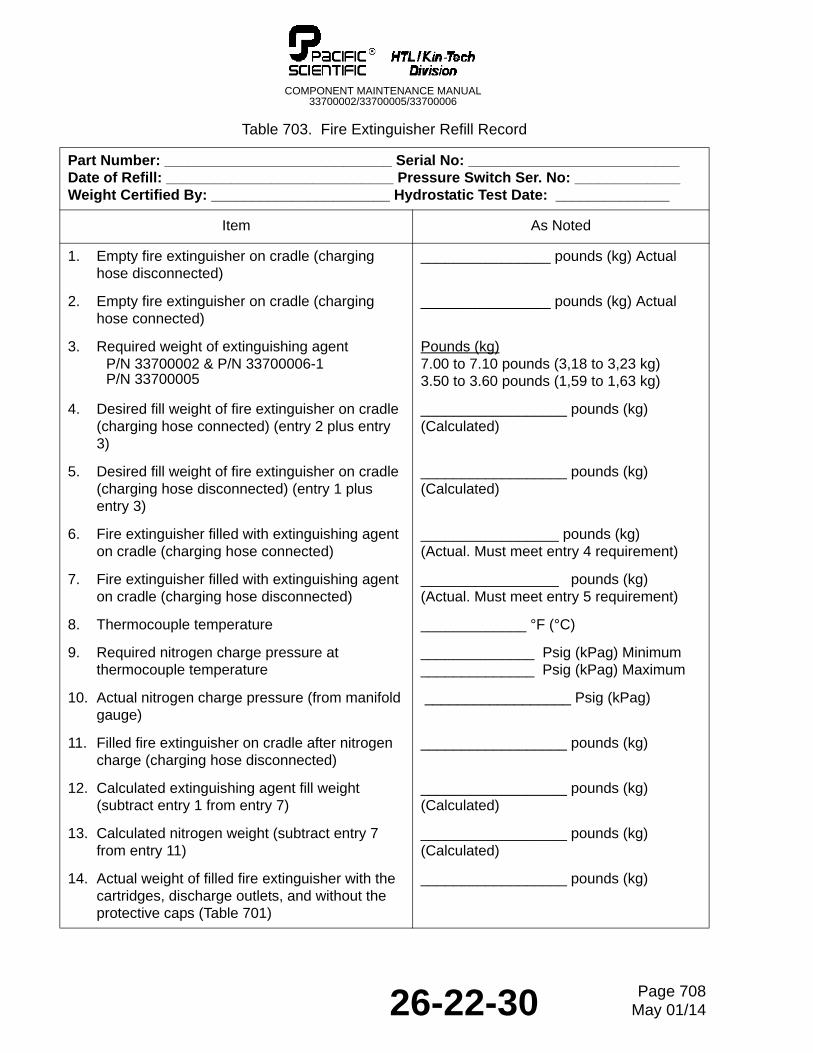
Table 703. Fire Extinguisher Refill Record
Part Number: ____________________________ Serial No: __________________________Date of Refill: ____________________________ Pressure Switch Ser. No: _____________Weight Certified By: ______________________ Hydrostatic Test Date: ______________
Item As Noted
1. Empty fire extinguisher on cradle (charging hose disconnected)
________________ pounds (kg) Actual
2. Empty fire extinguisher on cradle (charging hose connected)
________________ pounds (kg) Actual
3. Required weight of extinguishing agentP/N 33700002 & P/N 33700006-1P/N 33700005
Pounds (kg) 7.00 to 7.10 pounds (3,18 to 3,23 kg)3.50 to 3.60 pounds (1,59 to 1,63 kg)
4. Desired fill weight of fire extinguisher on cradle (charging hose connected) (entry 2 plus entry 3)
__________________ pounds (kg) (Calculated)
5. Desired fill weight of fire extinguisher on cradle (charging hose disconnected) (entry 1 plus entry 3)
__________________ pounds (kg) (Calculated)
6. Fire extinguisher filled with extinguishing agent on cradle (charging hose connected)
_________________ pounds (kg)(Actual. Must meet entry 4 requirement)
7. Fire extinguisher filled with extinguishing agent on cradle (charging hose disconnected)
_________________ pounds (kg)(Actual. Must meet entry 5 requirement)
8. Thermocouple temperature _____________ °F (°C)
9. Required nitrogen charge pressure at thermocouple temperature
______________ Psig (kPag) Minimum______________ Psig (kPag) Maximum
10. Actual nitrogen charge pressure (from manifold gauge)
__________________ Psig (kPag)
11. Filled fire extinguisher on cradle after nitrogen charge (charging hose disconnected)
__________________ pounds (kg)
12. Calculated extinguishing agent fill weight (subtract entry 1 from entry 7)
__________________ pounds (kg)(Calculated)
13. Calculated nitrogen weight (subtract entry 7 from entry 11)
__________________ pounds (kg)(Calculated)
14. Actual weight of filled fire extinguisher with the cartridges, discharge outlets, and without the protective caps (Table 701)
__________________ pounds (kg)
26-22-30 Page 708May 01/14
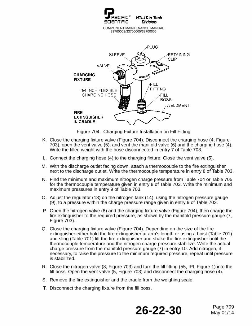
COMPONENT MAINTENANCE MANUAL33700002/33700005/33700006
Figure 704. Charging Fixture Installation on Fill Fitting
K. Close the charging fixture valve (Figure 704). Disconnect the charging hose (4, Figure 703), open the vent valve (5), and vent the manifold valve (6) and the charging hose (4). Write the filled weight with the hose disconnected in entry 7 of Table 703.
L. Connect the charging hose (4) to the charging fixture. Close the vent valve (5).
M. With the discharge outlet facing down, attach a thermocouple to the fire extinguisher next to the discharge outlet. Write the thermocouple temperature in entry 8 of Table 703.
N. Find the minimum and maximum nitrogen charge pressure from Table 704 or Table 705 for the thermocouple temperature given in entry 8 of Table 703. Write the minimum and maximum pressures in entry 9 of Table 703.
O. Adjust the regulator (13) on the nitrogen tank (14), using the nitrogen pressure gauge (9), to a pressure within the charge pressure range given in entry 9 of Table 703.
P. Open the nitrogen valve (8) and the charging fixture valve (Figure 704), then charge the fire extinguisher to the required pressure, as shown by the manifold pressure gauge (7, Figure 703).
Q. Close the charging fixture valve (Figure 704). Depending on the size of the fire extinguisher either hold the fire extinguisher at arm's length or using a hoist (Table 701) and sling (Table 701) lift the fire extinguisher and shake the fire extinguisher until the thermocouple temperature and the nitrogen charge pressure stabilize. Write the actual charge pressure from the manifold pressure gauge (7) in entry 10. Add nitrogen, if necessary, to raise the pressure to the minimum required pressure, repeat until pressure is stabilized.
R. Close the nitrogen valve (8, Figure 703) and turn the fill fitting (55, IPL Figure 1) into the fill boss. Open the vent valve (5, Figure 703) and disconnect the charging hose (4).
S. Remove the fire extinguisher and the cradle from the weighing scale.
T. Disconnect the charging fixture from the fill boss.
26-22-30 Page 709May 01/14
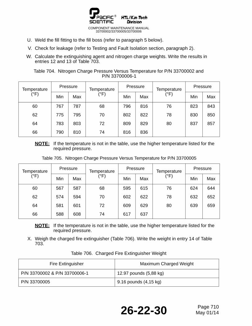
COMPONENT MAINTENANCE MANUAL33700002/33700005/33700006
U. Weld the fill fitting to the fill boss (refer to paragraph 5 below).
V. Check for leakage (refer to Testing and Fault Isolation section, paragraph 2).
W. Calculate the extinguishing agent and nitrogen charge weights. Write the results in entries 12 and 13 of Table 703.
NOTE: If the temperature is not in the table, use the higher temperature listed for the required pressure.
NOTE: If the temperature is not in the table, use the higher temperature listed for the required pressure.
X. Weigh the charged fire extinguisher (Table 706). Write the weight in entry 14 of Table 703.
Table 704. Nitrogen Charge Pressure Versus Temperature for P/N 33700002 and P/N 33700006-1
Temperature(°F)
PressureTemperature
(°F)
PressureTemperature
(°F)
Pressure
Min Max Min Max Min Max
60 767 787 68 796 816 76 823 843
62 775 795 70 802 822 78 830 850
64 783 803 72 809 829 80 837 857
66 790 810 74 816 836
Table 705. Nitrogen Charge Pressure Versus Temperature for P/N 33700005
Temperature(°F)
PressureTemperature
(°F)
PressureTemperature
(°F)
Pressure
Min Max Min Max Min Max
60 567 587 68 595 615 76 624 644
62 574 594 70 602 622 78 632 652
64 581 601 72 609 629 80 639 659
66 588 608 74 617 637
Table 706. Charged Fire Extinguisher Weight
Fire Extinguisher Maximum Charged Weight
P/N 33700002 & P/N 33700006-1 12.97 pounds (5,88 kg)
P/N 33700005 9.16 pounds (4,15 kg)
26-22-30 Page 710May 01/14
COMPONENT MAINTENANCE MANUAL33700002/33700005/33700006
Y. Weigh the complete unit and vibra-etch the charge weight (entry 14 of Table 703) and recharge date on the identification plate (100, IPL Figure 1). Do not use an impression or ink stamp.
Z. Install the discharge outlet and cartridge (refer to paragraph 6 below).
5. Fill Fitting
A. Attach the cradle (Table 701) to a rotary table on a machine tool (Table 701). See Figure 705.
B. Put the fire extinguisher in the cradle, with the fill boss up.
C. Clean the weld area with isopropyl alcohol (Table 701). Refer to the Cleaning section, paragraph 2.A.
D. Use the fill fitting adapter spanner wrench (Table 701) to turn the fill boss adapter (Table 701) into the rotating plate in the welding fixture (Table 701).
E. Install the welding fixture on the fill boss. Tighten the adapter setscrew to hold the fixture in place.
F. Turn the fill fitting heat sink (Table 701) into the fill fitting (55, IPL Figure 1). Raise the plunger disc on the welding fixture for clearance, if necessary.
G. Install a welding torch in the torch holder.
H. Adjust the tip of the welding torch to weld the fill fitting to the fill boss. Refer to Table 702 for the welding schedule.
I. Attach the ground wire to the machine tool (Table 701).
J. Hold the welding fixture by hand to keep it from turning, and weld the fill fitting to the fill boss.
WARNING: THE HEAT SINK (TABLE 701) WILL BE HOT. FOR SAFE HANDLING, USE HEAT RESISTANT GLOVES OR LET THE HEAT SINK COOL BEFORE HANDLING.
K. Remove the heat sink and the welding fixture (Table 701).
26-22-30 Page 711May 01/14
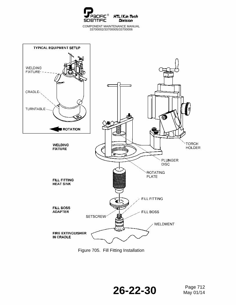
COMPONENT MAINTENANCE MANUAL33700002/33700005/33700006
Figure 705. Fill Fitting Installation
26-22-30 Page 712May 01/14
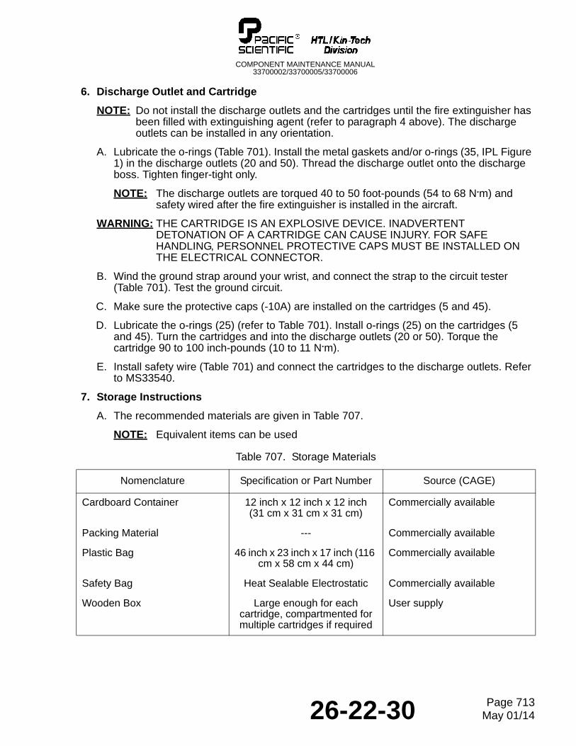
COMPONENT MAINTENANCE MANUAL33700002/33700005/33700006
6. Discharge Outlet and Cartridge
NOTE: Do not install the discharge outlets and the cartridges until the fire extinguisher has been filled with extinguishing agent (refer to paragraph 4 above). The discharge outlets can be installed in any orientation.
A. Lubricate the o-rings (Table 701). Install the metal gaskets and/or o-rings (35, IPL Figure 1) in the discharge outlets (20 and 50). Thread the discharge outlet onto the discharge boss. Tighten finger-tight only.
NOTE: The discharge outlets are torqued 40 to 50 foot-pounds (54 to 68 N.m) and safety wired after the fire extinguisher is installed in the aircraft.
WARNING: THE CARTRIDGE IS AN EXPLOSIVE DEVICE. INADVERTENT DETONATION OF A CARTRIDGE CAN CAUSE INJURY. FOR SAFE HANDLING, PERSONNEL PROTECTIVE CAPS MUST BE INSTALLED ON THE ELECTRICAL CONNECTOR.
B. Wind the ground strap around your wrist, and connect the strap to the circuit tester (Table 701). Test the ground circuit.
C. Make sure the protective caps (-10A) are installed on the cartridges (5 and 45).
D. Lubricate the o-rings (25) (refer to Table 701). Install o-rings (25) on the cartridges (5 and 45). Turn the cartridges and into the discharge outlets (20 or 50). Torque the cartridge 90 to 100 inch-pounds (10 to 11 N.m).
E. Install safety wire (Table 701) and connect the cartridges to the discharge outlets. Refer to MS33540.
7. Storage Instructions
A. The recommended materials are given in Table 707.
NOTE: Equivalent items can be used
Table 707. Storage Materials
Nomenclature Specification or Part Number Source (CAGE)
Cardboard Container 12 inch x 12 inch x 12 inch(31 cm x 31 cm x 31 cm)
Commercially available
Packing Material --- Commercially available
Plastic Bag 46 inch x 23 inch x 17 inch (116 cm x 58 cm x 44 cm)
Commercially available
Safety Bag Heat Sealable Electrostatic Commercially available
Wooden Box Large enough for each cartridge, compartmented for multiple cartridges if required
User supply
26-22-30 Page 713May 01/14
COMPONENT MAINTENANCE MANUAL33700002/33700005/33700006
B. Fire Extinguisher
NOTE: With the protective caps (-10A, IPL Figure 1) installed on the cartridges (5 and 45), it is safer to store the fire extinguishers with the cartridges installed in the discharge outlets.
(1) Install the protective caps (Table 701) on the pressure switch and discharge outlets. Make sure the protective caps (-10A) are installed on the cartridges (5 and 45).
(2) Insert the fire extinguisher into a plastic bag (Table 707) Put the fire extinguisher in a cardboard container (Table 707). Fill the cardboard container with packing material (Table 707), as needed to prevent damage to the components.
(3) Write the fire extinguisher part number, date of last hydrostatic test, and overhaul date on the outside of the cardboard container . Also, write the cartridge part number and the date of its Service/Storage Life.
(4) Attach the following warning/caution stickers to the outside of the cardboard container.
(a) Non-Flammable Gas
(b) Compressed Gases, N.O.S. (Bromotrifluoromethane, Nitrogen), UN1956
(c) Fragile - DO NOT DROP
(5) Storage temperatures are +40°F to +100°F (+4°C to +38°C).
C. Cartridge
WARNING: THE CARTRIDGE IS AN EXPLOSIVE DEVICE. INADVERTENT DETONATION OF A CARTRIDGE CAN CAUSE INJURY. FOR SAFE HANDLING, PERSONNEL MUST BE GROUNDED AND THE PROTECTIVE CAP MUST BE INSTALLED.
(1) Wind the ground strap around your wrist, and connect the strap to the circuit tester (Table 701). Test the ground circuit.
(2) Make sure the protective cap (-10A) are installed on the cartridges (5 or 45).
(3) Put the cartridge in an electrostatic safety bag (Table 707), then into a correctly sized wooden box (Table 707), and seal.
(4) Write the cartridge part number and the Service/Storage date on the outside of the wooden box. Mark the wooden box with Pyrotechnic, UN0323.
(5) Storage temperatures are +40°F to +100°F (+4°C to +38°C).
26-22-30 Page 714May 01/14
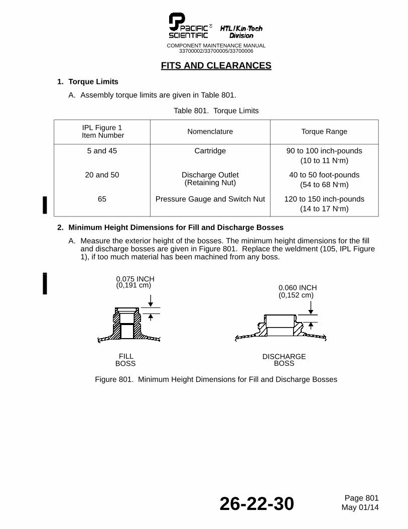
COMPONENT MAINTENANCE MANUAL33700002/33700005/33700006
FITS AND CLEARANCES
1. Torque Limits
A. Assembly torque limits are given in Table 801.
2. Minimum Height Dimensions for Fill and Discharge Bosses
A. Measure the exterior height of the bosses. The minimum height dimensions for the fill and discharge bosses are given in Figure 801. Replace the weldment (105, IPL Figure 1), if too much material has been machined from any boss.
Figure 801. Minimum Height Dimensions for Fill and Discharge Bosses
Table 801. Torque Limits
IPL Figure 1 Item Number Nomenclature Torque Range
5 and 45 Cartridge 90 to 100 inch-pounds(10 to 11 N.m)
20 and 50 Discharge Outlet(Retaining Nut)
40 to 50 foot-pounds(54 to 68 N.m)
65 Pressure Gauge and Switch Nut 120 to 150 inch-pounds(14 to 17 N.m)
FILLBOSS
DISCHARGEBOSS
0.075 INCH(0,191 cm) 0.060 INCH
(0,152 cm)
26-22-30 Page 801May 01/14

COMPONENT MAINTENANCE MANUAL33700002/33700005/33700006
THIS IS A BLANK PAGE
26-22-30 Page 802May 01/14
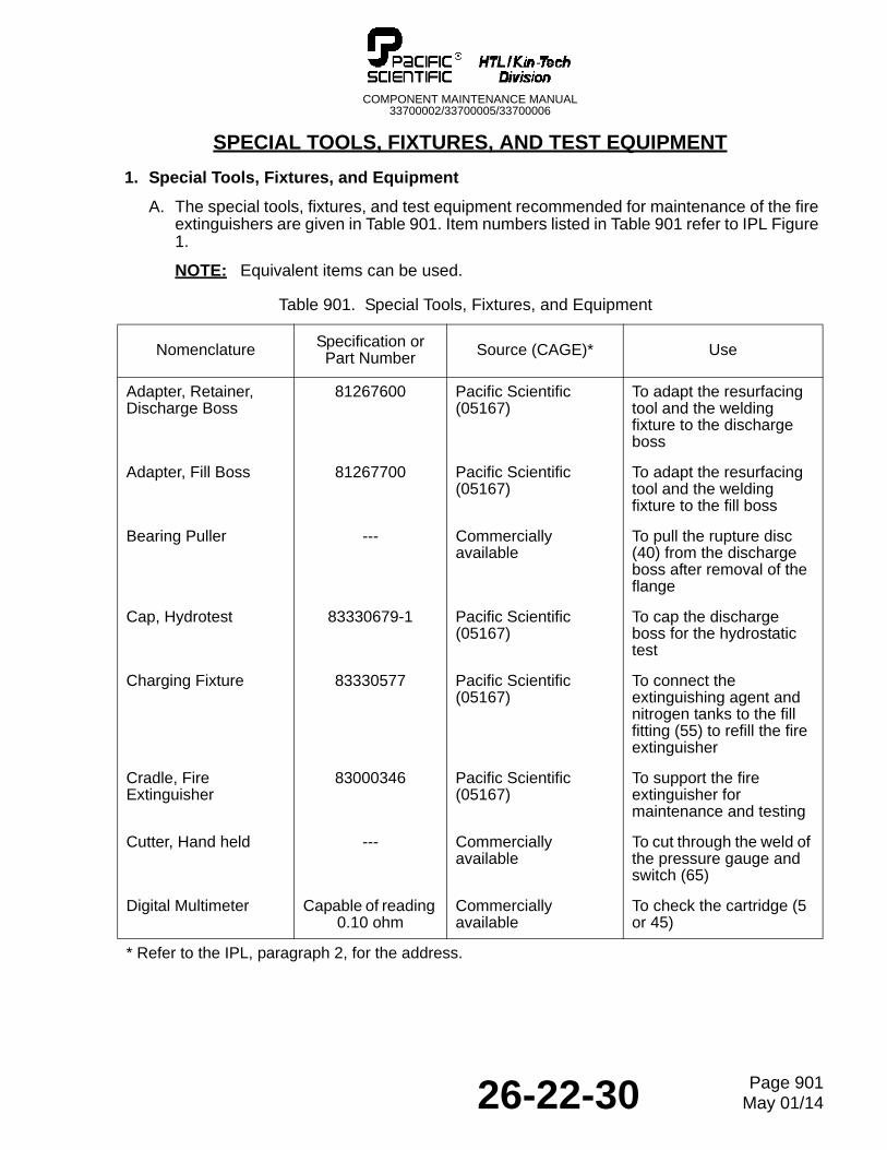
COMPONENT MAINTENANCE MANUAL33700002/33700005/33700006
SPECIAL TOOLS, FIXTURES, AND TEST EQUIPMENT
1. Special Tools, Fixtures, and Equipment
A. The special tools, fixtures, and test equipment recommended for maintenance of the fire extinguishers are given in Table 901. Item numbers listed in Table 901 refer to IPL Figure 1.
NOTE: Equivalent items can be used.
Table 901. Special Tools, Fixtures, and Equipment
Nomenclature Specification or Part Number Source (CAGE)* Use
Adapter, Retainer, Discharge Boss
81267600 Pacific Scientific (05167)
To adapt the resurfacing tool and the welding fixture to the discharge boss
Adapter, Fill Boss 81267700 Pacific Scientific (05167)
To adapt the resurfacing tool and the welding fixture to the fill boss
Bearing Puller --- Commercially available
To pull the rupture disc (40) from the discharge boss after removal of the flange
Cap, Hydrotest 83330679-1 Pacific Scientific (05167)
To cap the discharge boss for the hydrostatic test
Charging Fixture 83330577 Pacific Scientific (05167)
To connect the extinguishing agent and nitrogen tanks to the fill fitting (55) to refill the fire extinguisher
Cradle, Fire Extinguisher
83000346 Pacific Scientific (05167)
To support the fire extinguisher for maintenance and testing
Cutter, Hand held --- Commercially available
To cut through the weld of the pressure gauge and switch (65)
Digital Multimeter Capable of reading 0.10 ohm
Commercially available
To check the cartridge (5 or 45)
* Refer to the IPL, paragraph 2, for the address.
26-22-30 Page 901May 01/14
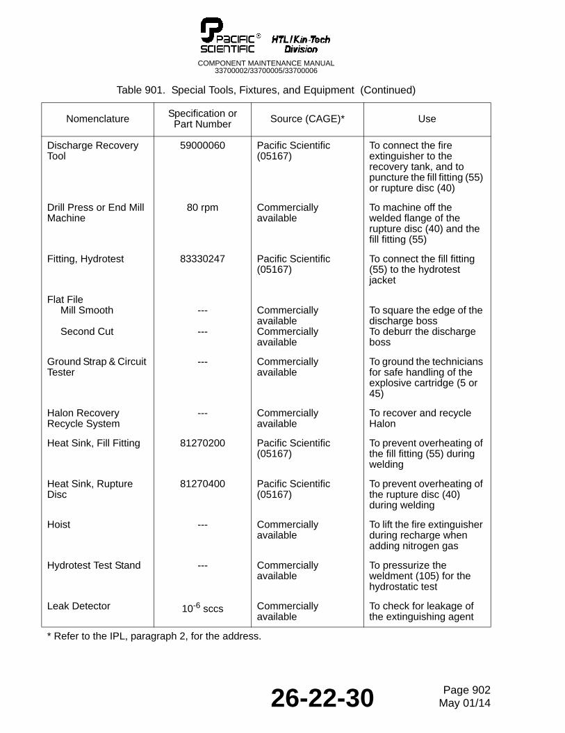
COMPONENT MAINTENANCE MANUAL33700002/33700005/33700006
Discharge Recovery Tool
59000060 Pacific Scientific (05167)
To connect the fire extinguisher to the recovery tank, and to puncture the fill fitting (55) or rupture disc (40)
Drill Press or End Mill Machine
80 rpm Commercially available
To machine off the welded flange of the rupture disc (40) and the fill fitting (55)
Fitting, Hydrotest 83330247 Pacific Scientific (05167)
To connect the fill fitting (55) to the hydrotest jacket
Flat FileMill Smooth
Second Cut
---
---
Commercially availableCommercially available
To square the edge of the discharge bossTo deburr the discharge boss
Ground Strap & Circuit Tester
--- Commercially available
To ground the technicians for safe handling of the explosive cartridge (5 or 45)
Halon Recovery Recycle System
--- Commercially available
To recover and recycle Halon
Heat Sink, Fill Fitting 81270200 Pacific Scientific (05167)
To prevent overheating of the fill fitting (55) during welding
Heat Sink, Rupture Disc
81270400 Pacific Scientific (05167)
To prevent overheating of the rupture disc (40) during welding
Hoist --- Commercially available
To lift the fire extinguisher during recharge when adding nitrogen gas
Hydrotest Test Stand --- Commercially available
To pressurize the weldment (105) for the hydrostatic test
Leak Detector 10-6 sccs Commercially available
To check for leakage of the extinguishing agent
Table 901. Special Tools, Fixtures, and Equipment (Continued)
Nomenclature Specification or Part Number Source (CAGE)* Use
* Refer to the IPL, paragraph 2, for the address.
26-22-30 Page 902May 01/14
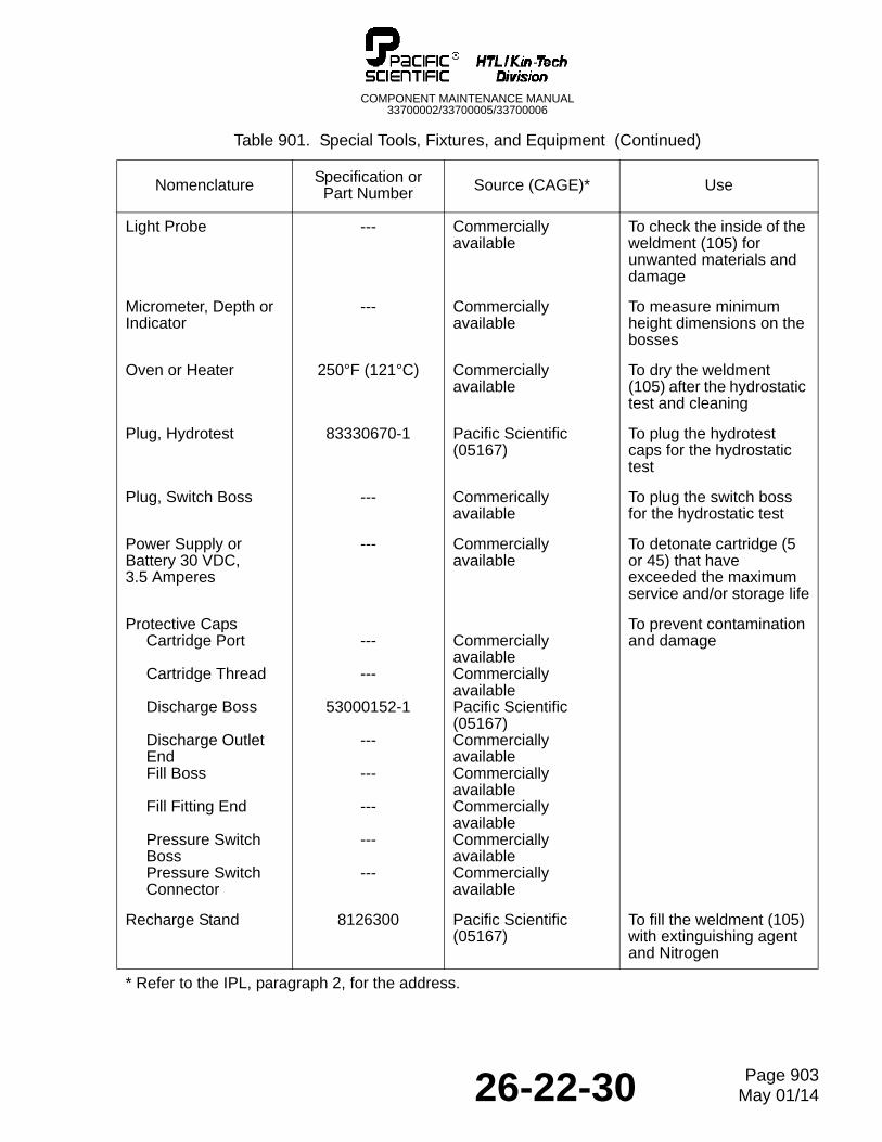
COMPONENT MAINTENANCE MANUAL33700002/33700005/33700006
Light Probe --- Commercially available
To check the inside of the weldment (105) for unwanted materials and damage
Micrometer, Depth or Indicator
--- Commercially available
To measure minimum height dimensions on the bosses
Oven or Heater 250°F (121°C) Commercially available
To dry the weldment (105) after the hydrostatic test and cleaning
Plug, Hydrotest 83330670-1 Pacific Scientific (05167)
To plug the hydrotest caps for the hydrostatic test
Plug, Switch Boss --- Commerically available
To plug the switch boss for the hydrostatic test
Power Supply or Battery 30 VDC, 3.5 Amperes
--- Commercially available
To detonate cartridge (5 or 45) that have exceeded the maximum service and/or storage life
Protective CapsCartridge Port
Cartridge Thread
Discharge Boss
Discharge Outlet EndFill Boss
Fill Fitting End
Pressure Switch BossPressure Switch Connector
---
---
53000152-1
---
---
---
---
---
Commercially availableCommercially availablePacific Scientific (05167)Commercially availableCommercially availableCommercially availableCommercially availableCommercially available
To prevent contamination and damage
Recharge Stand 8126300 Pacific Scientific (05167)
To fill the weldment (105) with extinguishing agent and Nitrogen
Table 901. Special Tools, Fixtures, and Equipment (Continued)
Nomenclature Specification or Part Number Source (CAGE)* Use
* Refer to the IPL, paragraph 2, for the address.
26-22-30 Page 903May 01/14
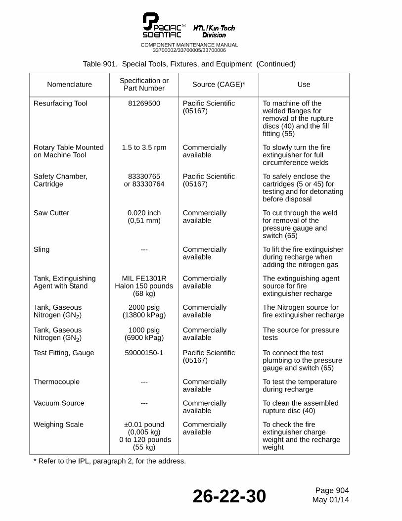
COMPONENT MAINTENANCE MANUAL33700002/33700005/33700006
Resurfacing Tool 81269500 Pacific Scientific (05167)
To machine off the welded flanges for removal of the rupture discs (40) and the fill fitting (55)
Rotary Table Mounted on Machine Tool
1.5 to 3.5 rpm Commercially available
To slowly turn the fire extinguisher for full circumference welds
Safety Chamber, Cartridge
83330765 or 83330764
Pacific Scientific (05167)
To safely enclose the cartridges (5 or 45) for testing and for detonating before disposal
Saw Cutter 0.020 inch(0,51 mm)
Commercially available
To cut through the weld for removal of the pressure gauge and switch (65)
Sling --- Commercially available
To lift the fire extinguisher during recharge when adding the nitrogen gas
Tank, Extinguishing Agent with Stand
MIL FE1301R Halon 150 pounds
(68 kg)
Commercially available
The extinguishing agent source for fire extinguisher recharge
Tank, Gaseous Nitrogen (GN2)
2000 psig (13800 kPag)
Commercially available
The Nitrogen source for fire extinguisher recharge
Tank, Gaseous Nitrogen (GN2)
1000 psig(6900 kPag)
Commercially available
The source for pressure tests
Test Fitting, Gauge 59000150-1 Pacific Scientific (05167)
To connect the test plumbing to the pressure gauge and switch (65)
Thermocouple --- Commercially available
To test the temperature during recharge
Vacuum Source --- Commercially available
To clean the assembled rupture disc (40)
Weighing Scale ±0.01 pound (0,005 kg)
0 to 120 pounds (55 kg)
Commercially available
To check the fire extinguisher charge weight and the recharge weight
Table 901. Special Tools, Fixtures, and Equipment (Continued)
Nomenclature Specification or Part Number Source (CAGE)* Use
* Refer to the IPL, paragraph 2, for the address.
26-22-30 Page 904May 01/14
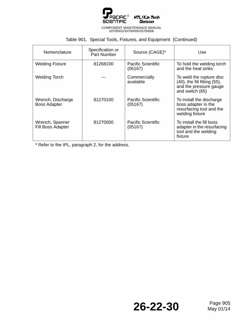
COMPONENT MAINTENANCE MANUAL33700002/33700005/33700006
Welding Fixture 81268100 Pacific Scientific (05167)
To hold the welding torch and the heat sinks
Welding Torch --- Commercially available
To weld the rupture disc (40), the fill fitting (55), and the pressure gauge and switch (65)
Wrench, Discharge Boss Adapter
81270100 Pacific Scientific (05167)
To install the discharge boss adapter in the resurfacing tool and the welding fixture
Wrench, SpannerFill Boss Adapter
81270000 Pacific Scientific (05167)
To install the fill boss adapter in the resurfacing tool and the welding fixture
Table 901. Special Tools, Fixtures, and Equipment (Continued)
Nomenclature Specification or Part Number Source (CAGE)* Use
* Refer to the IPL, paragraph 2, for the address.
26-22-30 Page 905May 01/14

COMPONENT MAINTENANCE MANUAL33700002/33700005/33700006
THIS IS A BLANK PAGE
26-22-30 Page 906May 01/14
COMPONENT MAINTENANCE MANUAL33700002/33700005/33700006
ILLUSTRATED PARTS LIST
1. Introduction
A. Purpose
(1) This IPL illustrates and lists the spare parts with attaching hardware.
B. Guide to use of the IPL
(1) If the part number is not known:
(a) Find the part in the illustration for the IPL Figure.
(b) Note the item number assigned to the part.
(c) Refer to the parts list and find the item number in the Fig & Item column.
(2) If the part number is known:
(a) Refer to the numerical index or parts list and find the part in the Part Number column.
(b) Note the figure number and item number assigned to the part.
(c) Refer to the illustration to find attaching hardware and related assembly parts.
2. Manufacturer Names and Address
A. The CAGE codes for the manufacturers of the parts, materials, special tools, and test equipment which may be referenced in this CMM are given below. The codes are taken from Cataloging Handbook H4/H8. The absence of a code in the Nomenclature column of the Detail Parts List means the part is manufactured or modified by the HTL/Kin-Tech Division of Pacific Scientific Company.
Code Name and Address Code Name and Address
05167
06186
Pacific Scientific CompanyHTL/Kin-Tech Division1915 Voyager AvenueSimi Valley, California 93063U.S.A.Tel: (805) 584-4100Fax: (805) 578-3400SITA LAXPSCR
DriLube Company711 West BroadwayGlendale, California 91204 U.S.A.
5R712
54636
Neutronics Inc.456 Creameny WayExton, Pennsylvaina19341-2532 U.S.A.Tel: (610) 524-8800Fax: (610) 524-8807
Sherwin-Williams Company101 Prospect Avenue N.W.Cleveland, Ohio 44115 U.S.A.
26-22-30 Page 1001May 01/14
COMPONENT MAINTENANCE MANUAL33700002/33700005/33700006
3. Explanation of Numerical Index Entries
A. The Numerical Index is provided to help find parts in the Detail Parts List by part number. The figure number, item number, and total quantity required are given for each entry.
B. The part numbers are arranged from left to right, one character at a time. The order of precedence is: (1) dash, (2) letter A through Z, and (3) numerals 0 through 9.
4. Explanation of Detail Parts List Entries
A. The Detail Parts List is arranged in general sequence of disassembly. The parts are illustrated in an exploded-view illustration and listed in the related parts list.
(1) Fig & Item Column
(a) The first number at the top of each Fig & Item column is the figure number of the corresponding illustration. The number given opposite each part number is the item number assigned to the part in the illustration.
(b) A dash (-) in front of an item number means the part is not illustrated.
(c) Alpha-variants A through Z (except I and O) are assigned to item numbers, when necessary to identify:
• Added parts• Alternate parts
• Service bulletin modified parts
(2) Part Number Column
(a) This column contains the manufacturer's part number for each part, as modified to meet the requirements of ATA 200/2000. These modifications can include:
1 Removal of blank spaces and special characters, with the possible exception of dashes. Dashes are permitted only between numeric characters.
2 Insertion of a reference part number compatible with ATA 200/2000 if the manufacturer's part number exceeds 15 characters. In these cases, the manufacturer's part number is given in the Nomenclature column.
(3) Nomenclature Column
(a) This column contains descriptive nomenclature for each part, the manufacturer's CAGE code (if the part is not manufactured by Pacific Scientific Company, HTL/Kin-Tech Division), part number (if longer than 15 characters or modified per ATA 200/2000), service bulletins affecting the part, and obsolete part numbers.
(b) The indenture system used in the Nomenclature column indicates the relationship of one part to another, as follows:1 2 3End Item or Major AssemblyATTACHING PARTSAttaching Parts for End Item or Major Assembly* * *. Detail Parts for End Item or Major Assembly. Subassemblies
26-22-30 Page 1002May 01/14
COMPONENT MAINTENANCE MANUAL33700002/33700005/33700006
ATTACHING PARTS. Attaching Parts for Subassemblies* * *. . Detail Parts for SubassembliesATTACHING PARTS. . Attaching Parts for Detail Parts* * *
(c) Assemblies, subassemblies, and detail parts subject to modification, deletion, addition, or replacement by an issued service bulletin, are annotated to indicate both pre- and post-service bulletin configurations. The term (PRE SB XXXX) in the Nomenclature column designates the original configuration, and the term (POST SB XXXX) identifies assemblies and parts after the modification has been completed.
(d) The terms defined below are used when applicable to indicate the interchangeability of parts.
(4) Eff Code (Effectivity Code) Column
(a) This column contains effectivity codes (A, B, etc) to indicate the alternate models or configurations of the end item to which the parts apply. This column is left blank when the parts apply to all models or configurations, included in the parts list.
(5) UPA (Units Per Assembly) Column
(a) The quantity shown in this column represents the units required for one NHA or, when referring to attaching parts, the quantity to attach one such item. The abbreviation RF (reference) indicates that the end item assembly is listed for reference purposes.
Term Abbreviation Definition
Alternate ALT The listed part is alternate to, and interchangeable with, other parts within the same item number variant group or other item numbers if designated.
Superseded By SUPSD BY The part is replaced by and is not interchangeable with the item number designated in the notation.
Supersedes SUPSDS The part replaces and is not interchangeable with the item number designated in the notation.
Replaced By REPLD BY The part is replaced by and is interchangeable with the item number designated in the notation.
Replaces REPLS The part replaces and is interchangeable with the item number designated in the notation.
26-22-30 Page 1003May 01/14

COMPONENT MAINTENANCE MANUAL33700002/33700005/33700006
THIS IS A BLANK PAGE
26-22-30 Page 1004May 01/14
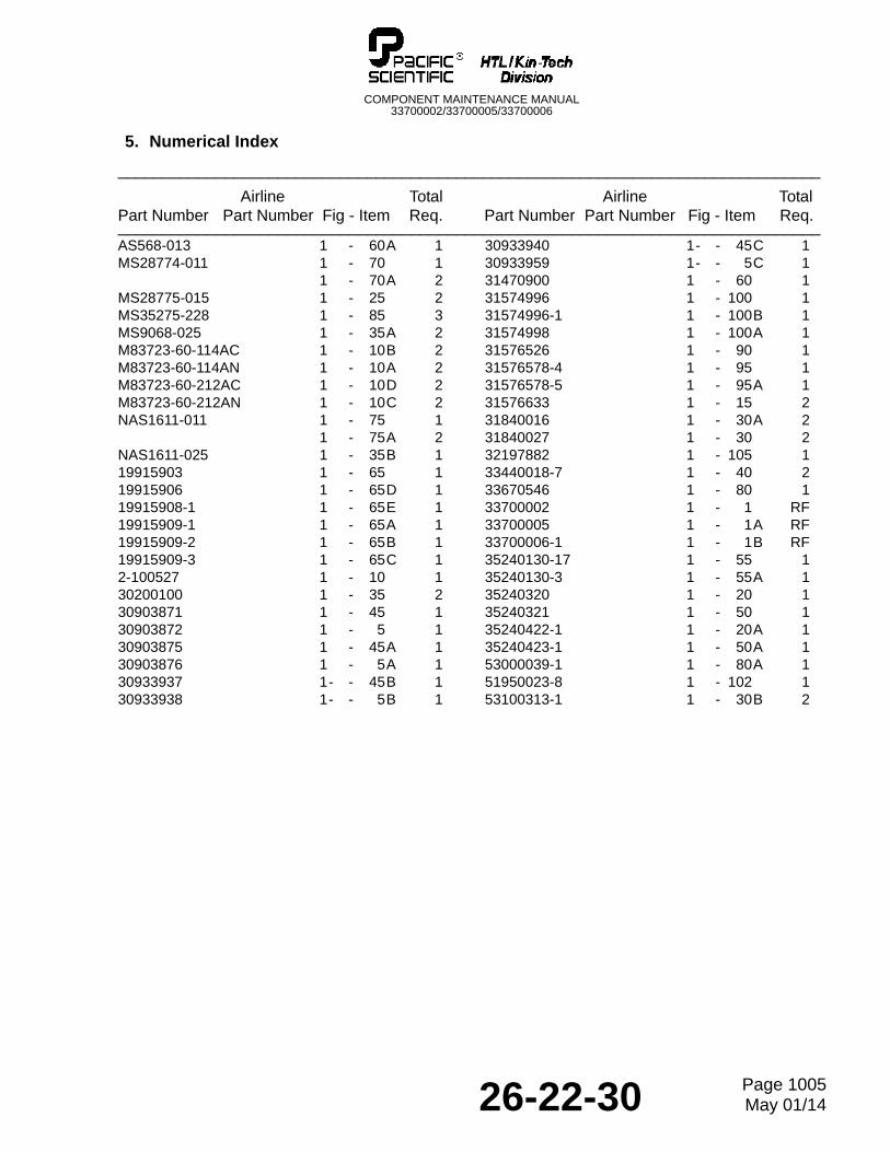
COMPONENT MAINTENANCE MANUAL33700002/33700005/33700006
5. Numerical Index
_______________________________________________________________________________
Airline Total Airline TotalPart Number Part Number Fig - Item Req. Part Number Part Number Fig - Item Req._______________________________________________________________________________AS568-013 1 - 60A 1MS28774-011 1 - 70 1
1 - 70A 2MS28775-015 1 - 25 2MS35275-228 1 - 85 3MS9068-025 1 - 35A 2M83723-60-114AC 1 - 10B 2M83723-60-114AN 1 - 10A 2M83723-60-212AC 1 - 10D 2M83723-60-212AN 1 - 10C 2NAS1611-011 1 - 75 1
1 - 75A 2NAS1611-025 1 - 35B 119915903 1 - 65 119915906 1 - 65D 119915908-1 1 - 65E 119915909-1 1 - 65A 119915909-2 1 - 65B 119915909-3 1 - 65C 12-100527 1 - 10 130200100 1 - 35 230903871 1 - 45 130903872 1 - 5 130903875 1 - 45A 130903876 1 - 5A 130933937 1- - 45B 130933938 1- - 5B 1
30933940 1- - 45C 130933959 1- - 5C 131470900 1 - 60 131574996 1 - 100 131574996-1 1 - 100B 131574998 1 - 100A 131576526 1 - 90 131576578-4 1 - 95 131576578-5 1 - 95A 131576633 1 - 15 231840016 1 - 30A 231840027 1 - 30 232197882 1 - 105 133440018-7 1 - 40 233670546 1 - 80 133700002 1 - 1 RF33700005 1 - 1A RF33700006-1 1 - 1B RF35240130-17 1 - 55 135240130-3 1 - 55A 135240320 1 - 20 135240321 1 - 50 135240422-1 1 - 20A 135240423-1 1 - 50A 153000039-1 1 - 80A 151950023-8 1 - 102 153100313-1 1 - 30B 2
26-22-30 Page 1005May 01/14

COMPONENT MAINTENANCE MANUAL33700002/33700005/33700006
THIS IS A BLANK PAGE
26-22-30 Page 1006May 01/14

COMPONENT MAINTENANCE MANUAL33700002/33700005/33700006
6. Detailed Parts List
NOTE: The items in this list are made or supplied by the HTL/Kin-Tech Division of Pacific Scientific, or by the suppliers shown in this list. Pacific Scientific does not give approval for items that are procured from suppliers who are not shown in this list. Approval from Pacific Scientific is not necessary for government and industry standard parts.
26-22-30 Page 1007May 01/14
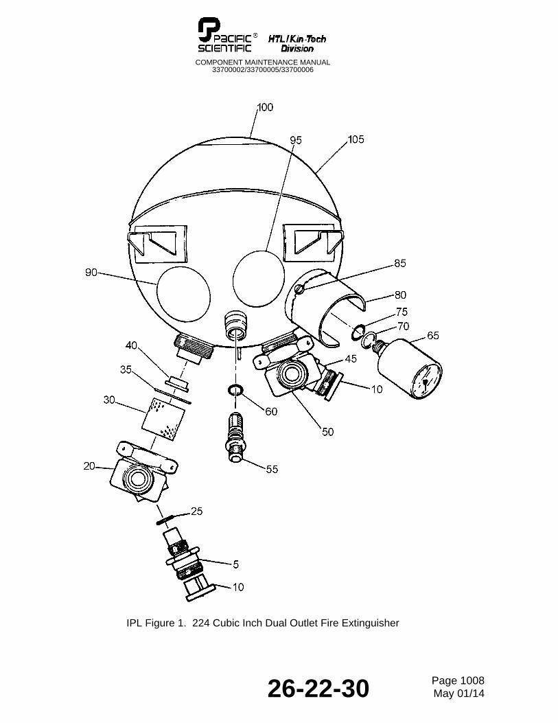
COMPONENT MAINTENANCE MANUAL33700002/33700005/33700006
IPL Figure 1. 224 Cubic Inch Dual Outlet Fire Extinguisher
26-22-30 Page 1008May 01/14
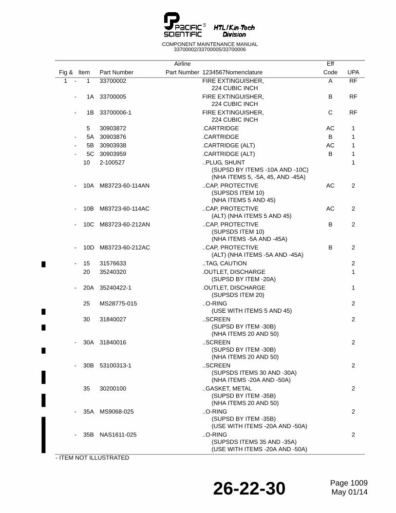
COMPONENT MAINTENANCE MANUAL33700002/33700005/33700006
Airline Eff
Fig & Item Part Number Part Number 1234567Nomenclature Code UPA
1 - 1 33700002 FIRE EXTINGUISHER,224 CUBIC INCH
A RF
- 1A 33700005 FIRE EXTINGUISHER,224 CUBIC INCH
B RF
- 1B 33700006-1 FIRE EXTINGUISHER,224 CUBIC INCH
C RF
5 30903872 .CARTRIDGE AC 1
- 5A 30903876 .CARTRIDGE B 1
- 5B 30903938 .CARTRIDGE (ALT) AC 1
- 5C 30903959 .CARTRIDGE (ALT) B 1
10 2-100527 ..PLUG, SHUNT(SUPSD BY ITEMS -10A AND -10C)(NHA ITEMS 5, -5A, 45, AND -45A)
1
- 10A M83723-60-114AN ..CAP, PROTECTIVE(SUPSDS ITEM 10)(NHA ITEMS 5 AND 45)
AC 2
- 10B M83723-60-114AC ..CAP, PROTECTIVE(ALT) (NHA ITEMS 5 AND 45)
AC 2
- 10C M83723-60-212AN ..CAP, PROTECTIVE(SUPSDS ITEM 10)(NHA ITEMS -5A AND -45A)
B 2
- 10D M83723-60-212AC ..CAP, PROTECTIVE(ALT) (NHA ITEMS -5A AND -45A)
B 2
- 15 31576633 ..TAG, CAUTION 2
20 35240320 .OUTLET, DISCHARGE (SUPSD BY ITEM -20A)
1
- 20A 35240422-1 .OUTLET, DISCHARGE (SUPSDS ITEM 20)
1
25 MS28775-015 ..O-RING(USE WITH ITEMS 5 AND 45)
2
30 31840027 ..SCREEN(SUPSD BY ITEM -30B)(NHA ITEMS 20 AND 50)
2
- 30A 31840016 ..SCREEN(SUPSD BY ITEM -30B)(NHA ITEMS 20 AND 50)
2
- 30B 53100313-1 ..SCREEN(SUPSDS ITEMS 30 AND -30A)(NHA ITEMS -20A AND -50A)
2
35 30200100 ..GASKET, METAL(SUPSD BY ITEM -35B)(NHA ITEMS 20 AND 50)
2
- 35A MS9068-025 ..O-RING(SUPSD BY ITEM -35B)(USE WITH ITEMS -20A AND -50A)
2
- 35B NAS1611-025 ..O-RING(SUPSDS ITEMS 35 AND -35A)(USE WITH ITEMS -20A AND -50A)
2
- ITEM NOT ILLUSTRATED
26-22-30 Page 1009May 01/14
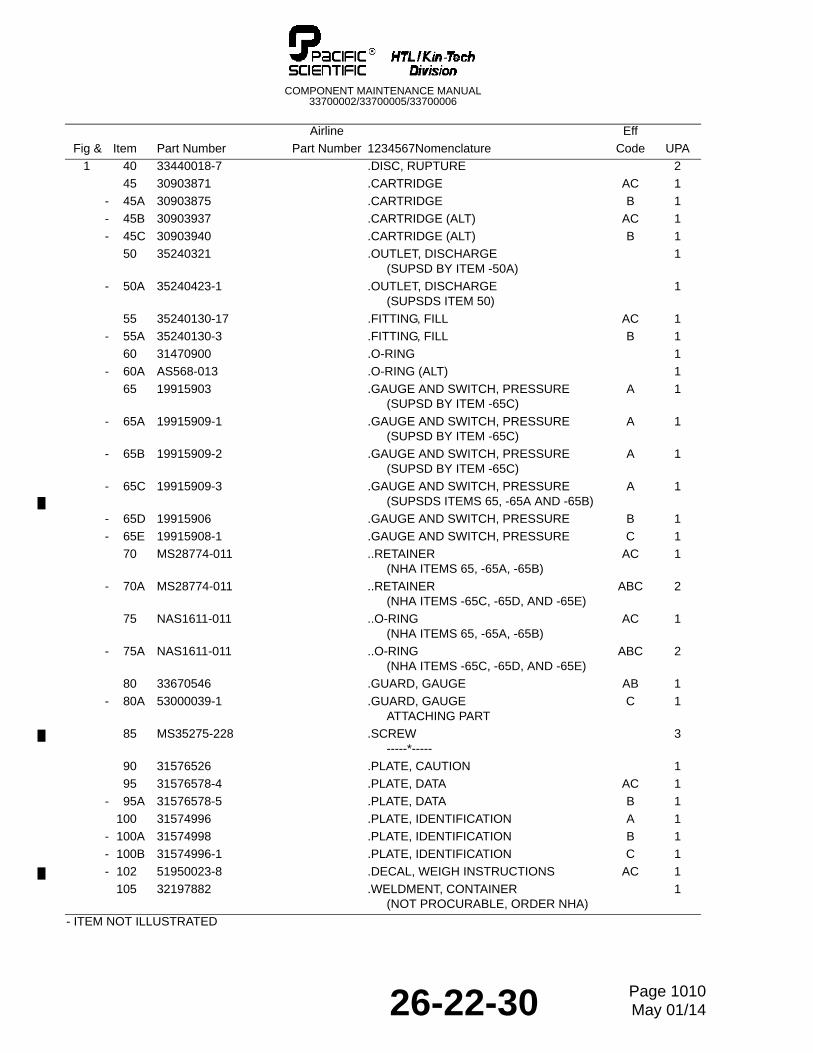
COMPONENT MAINTENANCE MANUAL33700002/33700005/33700006
1 40 33440018-7 .DISC, RUPTURE 2
45 30903871 .CARTRIDGE AC 1
- 45A 30903875 .CARTRIDGE B 1
- 45B 30903937 .CARTRIDGE (ALT) AC 1
- 45C 30903940 .CARTRIDGE (ALT) B 1
50 35240321 .OUTLET, DISCHARGE (SUPSD BY ITEM -50A)
1
- 50A 35240423-1 .OUTLET, DISCHARGE (SUPSDS ITEM 50)
1
55 35240130-17 .FITTING, FILL AC 1
- 55A 35240130-3 .FITTING, FILL B 1
60 31470900 .O-RING 1
- 60A AS568-013 .O-RING (ALT) 1
65 19915903 .GAUGE AND SWITCH, PRESSURE(SUPSD BY ITEM -65C)
A 1
- 65A 19915909-1 .GAUGE AND SWITCH, PRESSURE(SUPSD BY ITEM -65C)
A 1
- 65B 19915909-2 .GAUGE AND SWITCH, PRESSURE(SUPSD BY ITEM -65C)
A 1
- 65C 19915909-3 .GAUGE AND SWITCH, PRESSURE(SUPSDS ITEMS 65, -65A AND -65B)
A 1
- 65D 19915906 .GAUGE AND SWITCH, PRESSURE B 1
- 65E 19915908-1 .GAUGE AND SWITCH, PRESSURE C 1
70 MS28774-011 ..RETAINER(NHA ITEMS 65, -65A, -65B)
AC 1
- 70A MS28774-011 ..RETAINER(NHA ITEMS -65C, -65D, AND -65E)
ABC 2
75 NAS1611-011 ..O-RING(NHA ITEMS 65, -65A, -65B)
AC 1
- 75A NAS1611-011 ..O-RING(NHA ITEMS -65C, -65D, AND -65E)
ABC 2
80 33670546 .GUARD, GAUGE AB 1
- 80A 53000039-1 .GUARD, GAUGEATTACHING PART
C 1
85 MS35275-228 .SCREW-----*-----
3
90 31576526 .PLATE, CAUTION 1
95 31576578-4 .PLATE, DATA AC 1
- 95A 31576578-5 .PLATE, DATA B 1
100 31574996 .PLATE, IDENTIFICATION A 1
- 100A 31574998 .PLATE, IDENTIFICATION B 1
- 100B 31574996-1 .PLATE, IDENTIFICATION C 1
- 102 51950023-8 .DECAL, WEIGH INSTRUCTIONS AC 1
105 32197882 .WELDMENT, CONTAINER(NOT PROCURABLE, ORDER NHA)
1
Airline Eff
Fig & Item Part Number Part Number 1234567Nomenclature Code UPA
- ITEM NOT ILLUSTRATED
26-22-30 Page 1010May 01/14