cn32pt, cn16pt, cn16dpt, cn8pt, cn8dpt, cn8ept dp32pt ... · currently selected smart sensor value...
TRANSCRIPT

CN32Pt, CN16Pt, CN16DPt, CN8Pt, CN8DPt, CN8EPt
DP32Pt, DP16Pt, DP8Pt, DP8EPt
Modbus Interface

The information contained in this document is believed to be correct, but OMEGA accepts no liability for any errors it contains, and reserves the right to alter specifications without notice.

TABLE OF CONTENTS
1 Introduction ................................................................................................ 4
1.1 Purpose ................................................................................................................ 4
1.2 Definition of Terms and Acronyms ........................................................................ 4
1.3 Supporting Documents ......................................................................................... 4
2 Modbus Interface ........................................................................................ 5
2.1 Modbus Functions ................................................................................................ 5
2.2 Data Formats ........................................................................................................ 5
Multiple Register Reads ................................................................................................. 6
Multiple Register Writes ................................................................................................ 6
Request Packet Sizes ...................................................................................................... 6
Modbus USB Support ..................................................................................................... 7
3 Platinum Modbus Register Assignments ...................................................... 8
3.1 Non Volatile Memory Accesses ............................................................................. 8
3.2 Enumerated Values ............................................................................................. 19
Control/System Parameters......................................................................................... 19
Display & Formatting ................................................................................................... 20
Ramp and Soak Parameters ......................................................................................... 20
Input Parameters ......................................................................................................... 21
Setpoint Parameters .................................................................................................... 22
Alarm Parameters ........................................................................................................ 22
Output Parameters ...................................................................................................... 23
Annunciator Parameters .............................................................................................. 23
Communication Parameters ........................................................................................ 24
Excitation Parameters .................................................................................................. 25
Calibration Parameters ................................................................................................ 25
Input / Output Scaling .................................................................................................. 26
Figures
Figure 1- I/O Scaling. ............................................................................................................................ 26

PLATINUMTM Series Modbus Interface User’s Guide
4 Introduction
1 Introduction
1.1 Purpose
The following document defines the Modbus protocol support and register mapping used by the
Platinum product family.
The Modbus interface is available on all communication channels and support is provided for
MODBUS/ASCII, MODBUS/RTU and MODBUS/TCP/IP transactions.
1.2 Definition of Terms and Acronyms
I2C 2-wire serial interface ADC Analog to Digital Converter
Base Device
Device connected to slave device DAC Digital to Analog Converter
Smart Input
Device supporting 1 or more Input sensors
RS485 Electrical signals used for serial communications
Smart Output
Device supporting 1 or more Output Elements
RS232 Electrical signals used for serial communications
Sensor Element
One of the physical sensing elements on a Smart Output
CSV Comma Separated Values
AC Alternating Current COTS Commercially-Off-The-Shelf
DC Direct Current ESD Electro Static Discharge
CS Chip Select FW Firmware
RS232 Electrical signals used for serial communications
HW Hardware
CSV Comma Separated Values I/O Input/output
COTS Commercially-Off-The-Shelf LED Light Emitting Diode
ESD Electro Static Discharge Hexadecimal Values expressed using base 16 (24)
1.3 Supporting Documents
Doc. # Name / Description
M5457 Platinum Load and Save File Format
Platinum Ramp and Soak Processing
MODBUS APPLICATION PROTOCOL SPECIFICATION

PLATINUMTM Series Modbus Interface User’s Guide
5 Modbus Interface
2 Modbus Interface
The Modbus interface is fully described in MODBUS APPLICATION PROTOCOL SPECIFICATION
(V1.1b3).
The Modbus specification allows accessing to up 65535 internal ‘holding’ registers using register
READ, register WRITE and WRITE MULTIPLE commands. Each Modbus holding register is defined as a
16 bit entity structured as BIG ENDIAN values (most significant byte always presented first).
The Platinum Modbus interface provides access to the internal database of the Platinum product
family by internally mapping Modbus holding registers to specific database items.
Modbus is structured using a MASTER-SLAVE topology, in which there is one MASTER device and up
to 255 slave devices. All transactions are initiated by the MASTER device.
Modbus slave devices are individually accessed using a one byte SLAVE address. The MASTER device
initiates a transaction by sending a request packet to a specific slave. The SLAVE device processes
the transaction and returns either response packet indicating success or failure.
Address 0 is reserved as a ‘broadcast’ address, in which all slave devices will accept and process the
transaction but will not send a response.
2.1 Modbus Functions
The Platinum Modbus interface supports the following Modbus FUNCTION requests.
Function Code
Mnemonic Description
0x03 Read Holding Register Reads one or more consecutive 16 bit holding registers
0x06 Write Single Register Writes a specific 16 bit holding register
0x07 Read Exception status Reads structured status information
0x08 Diagnostic Read/Write diagnostic information
0x10 Write Multiple Registers Write one or more consecutive 16 bit holding registers
0x0b Get Comm events Read communication event counters
2.2 Data Formats
Modbus holding registers are represented as 16 bit entities. The following encoding is used for
extended data items. Note that ‘byte 0’ will be the first byte received/transmitted.
For data types that can be represented in 16 bit (Boolean, byte, char, int16 and uint16) a single
register is used.
For data types that require 32 bits two consecutive registers are used. The lower number register
will represent the most significant data. The 2nd register represents the leas significant data.

PLATINUMTM Series Modbus Interface User’s Guide
6 Modbus Interface
Multiple Register Reads
When reading a dual register entity the lower order register should be used as the requested
‘holding register’, with a request for a minimum of 2 registers. Internally the entire entity is read and
data is then built into a response packet.
The access can be split into 2 consecutive single register reads. When the lower (base) register is
accessed the entire 32 bit entity is read and the two most significant bytes are returned. The
following single register read must specify the next consecutive register address. The two least
significant bytes of the internally buffered data used in the response.
Attempts to access the two least significant bytes without first reading the two most significant
bytes will result in an error response.
Multiple Register Writes
When writing a dual register entity the lower order register should be used as the requested
‘holding register’, with a request for minimum of 2 registers. The write data is internally buffered
and transferred to the database entry as a 32 bit value.
The access can be split into 2 consecutive single register writes. When the lower (base) register is
written the 16 bit entity is internally buffered BUT NO DATA TRANSFER IS MADE TO THE DATABASE.
The following single register write must specify the next consecutive register address. The two least
significant bytes of the write request are combined with the previous write data and the entire 32
bit entity is written to the database.
Attempts to write the two least significant bytes without first writing the two most significant bytes
will result in an error response.
Data Types
Number of
Registers
Byte Description
0 1 2 3
Boolean 1 -- LSB
N/A
Zero = OFF, non-zero = ON
Byte, Char
1 -- LSB Entity contained in LSB of register, Byte 0 ignored.
Int16, uint16
1 MSB LSB Entity contained in MSB/LSB of register.
0 1 2 3 (dual register data)
Int32, uint32
2 MSB B-1 B-2 LSB Requires 2 consecutive registers, MSB transferred first
float 2 Sign+Exp
Mantisa MSB
B-1 Mantisa LSB
IEEE formatted value contained in 2 consecutive register
Request Packet Sizes
Multiple consecutive registers may be accessed in a single transaction.

PLATINUMTM Series Modbus Interface User’s Guide
7 Modbus Interface
The Platinum Modbus interface imposes a maximum of 64 bytes for the total transaction. Allowing
for the required framing, addressing and integrity checks results in the following data size
restrictions using the READ and WRITE MULTIPLE functions.
Format Protocol Overhead Maximum Read data Maximum Write data
ASCII 16 12 Registers 12 Registers
RTU 8 23 Registers 23 Registers
TCP/IP 8 23 Registers 23 Registers
Modbus USB Support
The Modbus specification supports RS232 and RS485 serial data. For ASCII formatted packets a USB
virtual comm channel provides full support since the framing information is specified by unique
characters (SOF = ‘:’, EOF = CR/LF).
For RTU formatted packets the Modbus requires specific inter-frame character timing to determine
the framing of each transaction. This information is not available using a generic virtual comm
channel across USB, which will typically collect ‘serial’ data into 64 byte packets for transmission, as
determined by the USB end-point buffer size. The USB Modbus RTU interface relies on the USB
channel collecting data into 64 byte packets.

PLATINUMTM Series Modbus Interface User’s Guide
8 Platinum Modbus Register Assignments
3 Platinum Modbus Register Assignments
All accesses to the Platinum database information is made thru the following Modbus registers.
Mnemonic entries marked with ‘*’ are identical to those used by the Platinum LOAD and SAVE file
formats.
Mnemonic entries marked with ‘**’ are identical to those used by the Platinum LOAD and SAVE file
formats but are referenced in LOAD and FILE data are made using Meta characters (%).
Data types are:
R – Single 16 bit register (may be Boolean, byte, char, and int16 or uint16 data)
L – Dual (32 bit) register (may be int32 or uint32 data)
F – IEEE Floating point value
All data is transferred using Big Endian formatting, where the most significant byte is transmitted
first.
3.1 Non Volatile Memory Accesses
The NV column indicates volatility. A ‘R” indicates the parameter is ‘Read Only.’ An ‘NV’ indicates a
non-volatile parameter which should be only written during configuration. Modbus traffic should
allow a minimum of 500 msec following a write to non-volatile memory. Standard memory accesses
should be limited to 10 transactions / second.
Index Mnemonic NV Type Description
512 0x0200 DEVICE_ID** R L Device Identifier
514 0x0202 VERSION_NUMBER** R L Version Number
516 0x0204 SYSTEM_STATUS R L Enumerated Status information
518 0x0206 BOOT_LOADER_VERSION R L Boot Loader Version
520 0x0208 HARDWARE_VERSION R L Hardware Version
522 0x020a SMART OUTPUT VERSION R L Smart Output Module Version
524 0x020c ISOLATED OUTPUT VERSION R L Isolated Output Module Version
528 0x0210 CURRENT_INPUT_VALUE R F Primary Input Scaled value
530 0x0212 REMOTE_SENSOR_VALUE F Internal Use Only
532 0x0214 REMOTE_SETPOINT_VALUE RW F
534 0x0216 SMART SENSOR VALUE R F Currently selected Smart Sensor value
542 0x021e INPUT_DIGITAL R R State of digital input pin
544 0x0220 CURRENT_SETPOINT_1 RW F Current value of Setpoint 1
546 0x0222 CURRENT_SETPOINT_2 RW F Current value of Setpoint 2
548 0x0224 CONTROL_SETPOINT RW F Setpoint used in PID calculations
550 0x0226 PEAK_VALUE RW F Maximum Value processed

PLATINUMTM Series Modbus Interface User’s Guide
9 Platinum Modbus Register Assignments
Index Mnemonic NV Type Description
552 0x0228 VALLEY_VALUE RW F Minimum Value processed
554 0x022a PID_OUTPUT R F PID Output level (0.100%)
556 0x022c CURRENT_INPUT_VALID R R Flag indicating process value is valid
557 0x022d ALARM_STATE R R
558 0x022e RAMP_SOAK_STATE R R Enumerated value - R&S state
560 0x0230 OUTPUT_1_STATE R R State of Output (0/1)
561 0x0231 OUTPUT_2_STATE R R State of Output (0/1)
562 0x0232 OUTPUT_3_STATE R R State of Output (0/1)
563 0x0233 OUTPUT_4_STATE R R State of Output (0/1)
564 0x0234 OUTPUT_5_STATE R R State of Output (0/1)
565 0x0235 OUTPUT_6_STATE R R State of Output (0/1)
566 0x0236 OUTPUT_7_STATE R R State of Output (0/1)
567 0x0237 OUTPUT_8_STATE R R State of Output (0/1)
Control Functions
576 0x0240 RUN_MODE RW R Enumerated value – system running state
577 0x0241 FACTORY_RESET W R Write 1 to force reset to factory defaults
578 0x0242 LATCH_RESET W R Write 1 to reset latched alarms
579 0x0243 PID_AUTOTUNE_START W R Write 1 to force Autotuning to start
580 0x0244 PID_AUTOTUNE_DONE R R Internal use only
581 0x0245 PROCESS_SCALE_ENABLE RW R Enables Scaling on Process values (LIVE/MANUAL)
582 0x0246 TARE_RESET W R Write 1 to force TARE
Display Functions
584 0x0248 READING_DECIMAL_POSITION* NV R Enumerated value – number of decimal points
585 0x0249 DISPLAY_UNITS* NV R Enumerated value – units of measure
586 0x024a DISPLAY_COLOR_NORMAL* NV R Enumerated value to set display color
587 0x024b DISPLAY_BRIGHTNESS* NV R Enumerated value to set display brightness
588 0x024c TIME_FORMAT* NV R Enumerated value to indicate time format
589 0x024d DISPLAY_ALARM_CONTROL R
590 0x024e DISPLAY ROUNDING NV F Determines display rounding
User Calibration
592 0x0250 TCAL_TYPE* NV R Enumerated value indicating type of TCAL
593 0x0251 SET_ICE_POINT NV R Write 1 to set ICE POINT offset
594 0x0252 SET_TCAL_1_POINT NV R Write 1 to set 1 point Cal. offset

PLATINUMTM Series Modbus Interface User’s Guide
10 Platinum Modbus Register Assignments
Index Mnemonic NV Type Description
595 0x0253 SET_TCAL_2_POINT_LOW NV R Write 1 to set 2 point Cal. LOW point
596 0x0254 SET_TCAL_2_POINT_HIGH NV R Write 1 to set 2 point Cal. HIGH point
600 0x0258 TCAL_ICE_POINT_OFFSET* NV F Stored ICE POINT offset
602 0x025a TCAL_1_POINT_OFFSET* NV F Stored 1 point CAL offset
604 0x025c TCAL_2_POINT_OFFSET* NV F Stored 2 point CAL offset
606 0x025e TCAL_2_POINT_GAIN* NV F Stored 2 point CAL gain
Ramp & Soak (Sequencer)
608 0x0260 RAMP_SOAK_MODE* NV R Enumerated – Ramp and Soak mode
609 0x0261 RAMP_SOAK_PROFILE_SELECT* RW R Starting Profile for Ramp and Soak
610 0x0262 CURRENT_PROFILE RW R Use to select R&S profile to access
611 0x0263 CURRENT_SEGMENT RW R Use to select profile segment to access
Ramp & Soak – Profile Specific
612 0x0264 SEGMENTS_PER_PROFILE* NV R Number of segments in current profile
613 0x0265 SOAK_ACTION* NV R Enumerated – Soak Action
614 0x0266 SOAK_LINK* NV R Profile to link to after current profile
615 0x0267 TRACKING_TYPE* NV R Enumerated – R&S tracking type
Ramp & Soak – Segment Specific
616 0x0268 RAMP_EVENT* NV R RE.ON flag set for current segment
617 0x0269 SOAK_EVENT* NV R SE.ON flag set for current segment
618 0x026a SOAK_PROCESS_VALUE* NV F Target SOAK setpoint for current segment
620 0x026c RAMP_TIME* NV L Time (msec) to reach target SOAK setpoint
622 0x026e SOAK_TIME* NV L Time (msec) to hold at SOAK setpoint
Ramp & Soak - Running Status
624 0x0270 CONTROL_SETPOINT RW F Setpoint used for PID/Control functions
626 0x0272 RAMP_SOAK_REMAINING_TIME R L Ramp or Soak time remaining
628 0x0274 RAMP_SOAK_STATE R R Enumerated – R&S flags
Input Type/Configuration
640 0x0280 CURRENT_INPUT_VALUE R F Current Process value
642 0x0282 INPUT_SENSOR* NV R Enumerated sensor (input) type
643 0x0283 TC_TYPE* NV R Enumerated Thermocouple type
644 0x0284 RTD_WIRE* NV R Enumerated RTD wire type

PLATINUMTM Series Modbus Interface User’s Guide
11 Platinum Modbus Register Assignments
Index Mnemonic NV Type Description
645 0x0285 RTD_ACRV_OHM_TYPE* NV R Enumerated RTD Curve
646 0x0286 THERMISTOR_VALUE* NV R Enumerated Thermistor type
647 0x0287 PROCESS_RANGE* NV R Enumerated process input range
648 0x0288 PROCESS TYPE* NV R Enumerated input type
653 0x028d TARE MODE NV R Tare Mode
654 0x028e RATE_MODE NV R Rate Mode (RESERVED)
655 0x028f READING_FILTER_CONSTANT* NV R Enumerated input filtering constant
Smart Sensors
656 0x0290 SMART SENSOR PRESET R R Enumerated Toggle
657 0x0291 SMART SENSOR SELECT NV R Selects active Sensor input
658 0x0292 SMART SENSOR READING 1 R F Sensor 1 Input
659 0x0294 SMART SENSOR READING 2 R F
660 0x0296 SMART SENSOR READING 3 R F
661 0x0298 SMART SENSOR READING 4 R F
PID Parameters
672 0x02a0 PID_ADAPTIVE_CONTROL_ENABLE*
NV R Enumerated Toggle
673 0x02a1 PID_ACTION* NV R Enumerated PID control action
674 0x02a2 PID_AUTOTUNE_TIMEOUT* NV L Timeout (msec) for Autotuning
676 0x02a4 PID_P_* NV F Proportional Gain value
678 0x02a6 PID_I_* NV F Integral Gain value
680 0x02a8 PID_D_* NV F Derivative Gain value
682 0x02aa PID_PERCENT_LOW* NV F Minimum PID Control output value
684 0x02ac PID_PERCENT_HIGH* NV F Maximum PID Control output value
686 0x02ae PID_MAX_RATE* NV F PID maximum rate of change
688 0x02b0 PID_ STABILITY_TIMEOUT* NV L Autotune stability test timeout
690 0x02b2 PID_ STABILITY_RATE* NV F Autotune maximum rate of change stability test
Safety
704 0x02c0 SAFETY_DELAYED_POWER_ON_RUN*
NV R Write 1 to DISABLE auto RUN on power up
705 0x02c1 SAFETY_DELAYED_OPER_RUN* NV R Write 1 to DISABLE return to RUN in OPER
706 0x02c2 SAFETY_SETPOINT_LIMIT_LOW* NV F Minimum allowed setpoint value
708 0x02c4 SAFETY_SETPOINT_LIMIT_HIGH* NV F Maximum allowed setpoint value
710 0x02c6 LOOP_BREAK_ENABLE* NV R Enumerated Toggle
712 0x02c8 LOOP_BREAK_TIME* NV L Time (msec) for break test
714 0x02ca OPEN_CIRCUIT_ENABLE* NV R Write 1 to enable open circuit test
Password / Access Control

PLATINUMTM Series Modbus Interface User’s Guide
12 Platinum Modbus Register Assignments
Index Mnemonic NV Type Description
720 0x02d0 PASSWORD_INIT_ENABLE* NV R Write 1 to enable INIT menu password
722 0x02d2 PASSWORD_INIT* NV L INIT menu password
724 0x02d4 PASSWORD_PROGRAM_ENABLE* NV R Write 1 to enable PROG menu password
726 0x02d6 PASSWORD_PROGRAM* NV L PROG menu password
Setpoints
736 0x02e0 SETPOINT_1_MODE* NV R Enumerated Setpoint 1 mode
738 0x02e2 ABSOLUTE SETPOINT_1* NV F Setpoint 1 Absolute value
740 0x02e8 SETPOINT_2_MODE* NV R Enumerated Setpoint 2 mode
742 0x02ea ABSOLUTE_SETPOINT_2* NV F Setpoint 2 Absolute value
744 0x02ec DEVIATION_SETPOINT_2* NV F Setpoint 2 value (derivative mode)
Process Input Range (Scaling)
768 0x0300 DB_4_20_MANUAL_LIVE* NV R Enumerated Input Process mode
770 0x0302 DB_4_20_READING_1* NV F Scale reading value 1
772 0x0304 DB_4_20_INPUT_1* NV F Scale input value 1
774 0x0306 DB_4_20_READING_2* NV F Scale reading value 2
776 0x0308 DB_4_20_INPUT_2* NV F Scale input value 2
800 0x0320 DB_0_24_MANUAL_LIVE* NV R Enumerated Input Process mode
802 0x0322 DB_0_24_ READING_1* NV F Scale reading value 1
804 0x0324 DB_0_24_ INPUT_1* NV F Scale input value 1
806 0x0326 DB_0_24_ READING_2* NV F Scale reading value 2
808 0x0328 DB_0_24_ INPUT_2* NV F Scale input value 2
832 0x0340 DB_10_MANUAL_LIVE* NV R Enumerated Input Process mode
834 0x0342 DB_10_ READING_1* NV F Scale reading value 1
836 0x0344 DB_10_INPUT_1* NV F Scale input value 1
838 0x0346 DB_10_READING_2* NV F Scale reading value 2
840 0x0348 DB_10_INPUT_2* NV F Scale input value 2
864 0x0360 DB_1_MANUAL_LIVE* NV R Enumerated Input Process mode
866 0x0362 DB_1_ READING_1* NV F Scale reading value 1
868 0x0364 DB_1_ INPUT_1* NV F Scale input value 1
870 0x0366 DB_1_READING_2* NV F Scale reading value 2
872 0x0368 DB_1_ INPUT_2* NV F Scale input value 2
896 0x0380 DB_POINT_1_MANUAL_ LIVE* NV R Enumerated Input Process mode
898 0x0382 DB_POINT_1_ READING_1* NV F Scale reading value 1
890 0x0384 DB_POINT_1_ INPUT_1* NV F Scale input value 1
892 0x0386 DB_POINT_1_ READING_2* NV F Scale reading value 2
894 0x0388 DB_POINT_1_ INPUT_2* NV F Scale input value 2
928 0x03a0 DB_POINT_05_MANUAL_LIVE* NV R Enumerated Input Process mode
930 0x03a2 DB_POINT_05_READING_1* NV F Scale reading value 1

PLATINUMTM Series Modbus Interface User’s Guide
13 Platinum Modbus Register Assignments
Index Mnemonic NV Type Description
932 0x03a4 DB_POINT_05_INPUT_1* NV F Scale input value 1
934 0x03a6 DB_POINT_05_READING_2* NV F Scale reading value 2
936 0x03a8 DB_POINT_05_INPUT_2* NV F Scale input value 2
Auxiliary Input (Remote Setpoint)
976 0x03d0 RSP_PROCESS_RANGE* NV R Enumerated Process Range
977 0x03d2 RSP_ENABLE* NV R Enumerated Toggle (sets SP 1 mode)
Auxiliary Input Scaling
984 0x03d8 RSP_4_20_SETPOINT_MIN* NV F Minimum Setpoint
986 0x03da RSP_4_20_INPUT_MIN* NV F Minimum Input
988 0x03dc RSP_4_20_SETPPOINT_MAX* NV F Maximum Setpoint
990 0x03de RSP_4_20_INPUT_MAX* NV F Maximum Input
992 0x03e0 RSP_0_24_SETPOINT_MIN* NV F
994 0x03e2 RSP_0_24_INPUT_MIN* NV F
996 0x03e4 RSP_0_24_SETPOINT_MAX* NV F
998 0x03e6 RSP_0_24_INPUT_MAX* NV F
1000 0x03e8 RSP_0_10_SETPOINT_MIN* NV F
1002 0x03ea RSP_0_10_INPUT_MIN* NV F
1004 0x03ec RSP_0_10_SETPOINT_MAX* NV F
1006 0x03ee RSP_0_10_INPUT_MAX* NV F
1008 0x03f0 RSP_0_1_SETPOINT_MIN* NV F
1010 0x03f2 RSP_0_1_INPUT_MIN* NV F
1012 0x03f4 RSP_0_1_SETPOINT_MAX* NV F
1014 0x03f6 RSP_0_1_INPUT_MAX* NV F
Output Configuration
1024 0x0400 OUTPUT_1_HW_TYPE R R Enumerated Hardware Type – upper 4 bits provide the ‘Instance’ count
1025 0x0401 OUTPUT_1_MODE* NV R Enumerated Output Mode
1026 0x0402 OUTPUT_1_ON_OFF_ACTION* NV R Enumerated On-Off Action
1027 0x0403 OUTPUT_1_SETPOINT* NV R Output Setpoint selection
1028 0x0404 OUTPUT_1_PULSE_LENGTH* NV F Pulse Length (.1 sec increments)
1030 0x0406 OUTPUT_1_ON_OFF_DEADBAND* NV F Deadband
1032 0x0408 OUTPUT_1_OUTPUT_RANGE* NV R Enumerated Output Analog Range
1034 0x040a OUTPUT_1_RETRAN_READING_1* NV F Retransmission Reading Low
1036 0x040c OUTPUT_1_RETRAN_OUTPUT_1* NV F Output Level Low
1038 0x040e OUTPUT_1_RETRAN_READING_2* NV F Retransmission Reading High
1040 0x0410 OUTPUT_1_RETRAN_OUTPUT_2* NV F Output Level High

PLATINUMTM Series Modbus Interface User’s Guide
14 Platinum Modbus Register Assignments
Index Mnemonic NV Type Description
1056 0x0420 OUTPUT_2_HW_TYPE R R Enumerated Hardware Type – upper 4 bits provide the ‘Instance’ count
1057 0x0421 OUTPUT_2_MODE* NV R Enumerated Output Mode
1058 0x0422 OUTPUT_2_ON_OFF_ACTION* NV R Enumerated On-Off Action
1059 0x0423 OUTPUT_2_SETPOINT* NV R Output Setpoint selection
1060 0x0424 OUTPUT_2_PULSE_LENGTH* NV F Pulse Length (.1 sec increments)
1062 0x0426 OUTPUT_2_ON_OFF_DEADBAND* NV F Deadband
1064 0x0428 OUTPUT_2_OUTPUT_RANGE* NV R Enumerated Output Analog Range
1066 0x042a OUTPUT_2_RETRAN_READING_1* NV F Retransmission Reading Low
1068 0x042c OUTPUT_2_RETRAN_OUTPUT_1* NV F Output Level Low
1070 0x042e OUTPUT_2_RETRAN_READING_2* NV F Retransmission Reading High
1072 0x0430 OUTPUT_2_RETRAN_OUTPUT_2* NV F Output Level High
1088 0x0440 OUTPUT_3_HW_TYPE R R Enumerated Hardware Type – upper 4 bits provide the ‘Instance’ count
1089 0x0441 OUTPUT_3_MODE* NV R Enumerated Output Mode
1090 0x0442 OUTPUT_3_ON_OFF_ACTION* NV R Enumerated On-Off Action
1091 0x0443 OUTPUT_3_SETPOINT* NV R Output Setpoint selection
1092 0x0444 OUTPUT_3_PULSE_LENGTH* NV F Pulse Length (.1 sec increments)
1094 0x0446 OUTPUT_3_ON_OFF_DEADBAND* NV F Deadband
1096 0x0448 OUTPUT_3_OUTPUT_RANGE* NV R Enumerated Output Analog Range
1098 0x044a OUTPUT_3_RETRAN_READING_1* NV F Retransmission Reading Low
1100 0x044c OUTPUT_3_RETRAN_OUTPUT_1* NV F Output Level Low
1102 0x044e OUTPUT_3_RETRAN_READING_2* NV F Retransmission Reading High
1104 0x0450 OUTPUT_3_RETRAN_OUTPUT_2* NV F Output Level High
1120 0x0460 OUTPUT_4_HW_TYPE R R Enumerated Hardware Type – upper 4 bits provide the ‘Instance’ count
1121 0x0461 OUTPUT_4_MODE* NV R Enumerated Output Mode
1122 0x0462 OUTPUT_4_ON_OFF_ACTION* NV R Enumerated On-Off Action
1123 0x0463 OUTPUT_4_SETPOINT* NV R Output Setpoint selection
1124 0x0464 OUTPUT_4_PULSE_LENGTH* NV F Pulse Length (.1 sec increments)
1126 0x0466 OUTPUT_4_ON_OFF_DEADBAND* NV F Deadband
1128 0x0468 OUTPUT_4_OUTPUT_RANGE* NV R Enumerated Output Analog Range
1130 0x046a OUTPUT_4_RETRAN_READING_1* NV F Retransmission Reading Low
1132 0x046c OUTPUT_4_RETRAN_OUTPUT_1* NV F Output Level Low
1134 0x046e OUTPUT_4_RETRAN_READING_2* NV F Retransmission Reading High
1136 0x0470 OUTPUT_4_RETRAN_OUTPUT_28 NV F Output Level High

PLATINUMTM Series Modbus Interface User’s Guide
15 Platinum Modbus Register Assignments
Index Mnemonic NV Type Description
1152 0x0480 OUTPUT_5_HW_TYPE R R Enumerated Hardware Type – upper 4 bits provide the ‘Instance’ count
1153 0x0481 OUTPUT_5_MODE* NV R Enumerated Output Mode
1154 0x0482 OUTPUT_5_ON_OFF_ACTION* NV R Enumerated On-Off Action
1155 0x0483 OUTPUT_5_SETPOINT* NV R Output Setpoint selection
1156 0x0484 OUTPUT_5_PULSE_LENGTH* NV F Pulse Length (.1 sec increments)
1158 0x0486 OUTPUT_5_ON_OFF_DEADBAND* NV F Deadband
1160 0x0488 OUTPUT_5_OUTPUT_RANGE* NV R Enumerated Output Analog Range
1162 0x048a OUTPUT_5_RETRAN_READING_1* NV F Retransmission Reading Low
1164 0x048c OUTPUT_5_RETRAN_OUTPUT_1* NV F Output Level Low
1165 0x048e OUTPUT_5_RETRAN_READING_2* NV F Retransmission Reading High
1168 0x0490 OUTPUT_5_RETRAN_OUTPUT_28 NV F Output Level High
1184 0x04a0 OUTPUT_6_HW_TYPE R R Enumerated Hardware Type – upper 4 bits provide the ‘Instance’ count
1185 0x04a1 OUTPUT_6_MODE* NV R Enumerated Output Mode
1186 0x04a2 OUTPUT_6_ON_OFF_ACTION* NV R Enumerated On-Off Action
1187 0x04a3 OUTPUT_6_SETPOINT* NV R Output Setpoint selection
1188 0x04a4 OUTPUT_6_PULSE_LENGTH* NV F Pulse Length (.1 sec increments)
1190 0x04a6 OUTPUT_6_ON_OFF_DEADBAND* NV F Deadband
1192 0x04a8 OUTPUT_6_OUTPUT_RANGE* NV R Enumerated Output Analog Range
1194 0x04aa OUTPUT_6_RETRAN_READING_1* NV F Retransmission Reading Low
1196 0x04ac OUTPUT_6_RETRAN_OUTPUT_1* NV F Output Level Low
1198 0x04ae OUTPUT_6_RETRAN_READING_2* NV F Retransmission Reading High
1200 0x04b0 OUTPUT_6_RETRAN_OUTPUT_28 NV F Output Level High
1216 0x04c0 OUTPUT_7_HW_TYPE R R Enumerated Hardware Type – upper 4 bits provide the ‘Instance’ count
1217 0x04c1 OUTPUT_7_MODE* NV R Enumerated Output Mode
1218 0x04c2 OUTPUT_7_ON_OFF_ACTION* NV R Enumerated On-Off Action
1219 0x04c3 OUTPUT_7_SETPOINT* NV R Output Setpoint selection
1220 0x04c4 OUTPUT_7_PULSE_LENGTH* NV F Pulse Length (.1 sec increments)
1222 0x04c6 OUTPUT_7_ON_OFF_DEADBAND* NV F Deadband
1224 0x04c8 OUTPUT_7_OUTPUT_RANGE* NV R Enumerated Output Analog Range
1226 0x04ca OUTPUT_7_RETRAN_READING_1* NV F Retransmission Reading Low
1228 0x04cc OUTPUT_7_RETRAN_OUTPUT_1* NV F Output Level Low
1230 0x04ce OUTPUT_7_RETRAN_READING_2* NV F Retransmission Reading High
1232 0x04d0 OUTPUT_7_RETRAN_OUTPUT_28 NV F Output Level High

PLATINUMTM Series Modbus Interface User’s Guide
16 Platinum Modbus Register Assignments
Index Mnemonic NV Type Description
1248 0x04e0 OUTPUT_8_HW_TYPE R R Enumerated Hardware Type – upper 4 bits provide the ‘Instance’ count
1259 0x04e1 OUTPUT_8_MODE* NV R Enumerated Output Mode
1250 0x04e2 OUTPUT_8_ON_OFF_ACTION* NV R Enumerated On-Off Action
1251 0x04e3 OUTPUT_8_SETPOINT* NV R Output Setpoint selection
1252 0x04e4 OUTPUT_8_PULSE_LENGTH* NV F Pulse Length (.1 sec increments)
1254 0x04e6 OUTPUT_8_ON_OFF_DEADBAND* NV F Deadband
1256 0x04e8 OUTPUT_8_OUTPUT_RANGE* NV R Enumerated Output Analog Range
1258 0x04ea OUTPUT_8_RETRAN_READING_1* NV F Retransmission Reading Low
1260 0x04ec OUTPUT_8_RETRAN_OUTPUT_1* NV F Output Level Low
1262 0x04ee OUTPUT_8_RETRAN_READING_2* NV F Retransmission Reading High
1264 0x04f0 OUTPUT_8_RETRAN_OUTPUT_28 NV F Output Level High
Alarm Configuration
1280 0x0500 ALARM_STATE R R Alarm state (Bit 0)
1281 0x0501 ALARM_1_TYPE* NV R Enumerated Alarm type
1282 0x0502 ALARM_1_MODE* NV R Enumerated Alarm Mode
1283 0x0503 ALARM_1_DISPLAY_COLOR* NV R Enumerated Alarm Color
1284 0x0504 ALARM_1_HIGH_HIGH_MODE* NV R Enumerated Toggle value
1285 0x0505 ALARM_1_LATCH_TYPE* NV R Enumerated Toggle value
1286 0x0506 ALARM_1_CONTACT_CLOSURE_TYPE*
NV R Enumerated Contact closure type
1287 0x0507 ALARM_1_POWER_ON_STATE* NV R Enumerated Power on control
1288 0x0508 ABSOLUTE_ALARM_1_LOW* NV F Alarm Low value (Absolute mode)
1290 0x050a ABSOLUTE_ALARM_1_HIGH* NV F Alarm High value (Absolute mode)
1292 0x050c DEVIATION_ALARM_1_LOW* NV F Alarm Low offset (Deviation mode)
1294 0x050e DEVIATION_ALARM_1_HIGH* NV F Alarm High offset (Deviation mode)
1296 0x0510 ALARM_1_HIGH_HIGH_OFFSET* NV F Alarm High-High offset
1298 0x0512 ALARM_1_ON_DELAY* NV F Alarm On Delay
1300 0x0514 ALARM_1_OFF_DELAY* NV F Alarm Off Delay
1312 0x0520 ALARM_STATE R R Alarm state (Bit 0)
1313 0x0521 ALARM_2_TYPE* NV R Enumerated Alarm type
1314 0x0522 ALARM_2_MODE* NV R Enumerated Alarm Mode
1315 0x0523 ALARM_2_DISPLAY_COLOR* NV R Enumerated Alarm Color
1316 0x0524 ALARM_2_HIGH_HIGH_MODE* NV R Enumerated Toggle value
1317 0x0525 ALARM_2_LATCH_TYPE* NV R Enumerated Toggle value
1318 0x0526 ALARM_2_CONTACT_CLOSURE_TYPE*
NV R Enumerated Contact closure type
1319 0x0527 ALARM_2_POWER_ON_STATE* NV R Enumerated Power on control

PLATINUMTM Series Modbus Interface User’s Guide
17 Platinum Modbus Register Assignments
Index Mnemonic NV Type Description
1320 0x0528 ABSOLUTE_ALARM_2_LOW* NV F Alarm Low value (Absolute mode)
1322 0x052a ABSOLUTE_ALARM_2_HIGH* NV F Alarm High value (Absolute mode)
1324 0x052c DEVIATION_ALARM_2_LOW* NV F Alarm Low offset (Deviation mode)
1326 0x052e DEVIATION_ALARM_2_HIGH* NV F Alarm High offset (Deviation mode)
1328 0x0530 ALARM_2_HIGH_HIGH_OFFSET* NV F Alarm High-High offset
1330 0x0532 ALARM_2_ON_DELAY* NV F Alarm On Delay
1332 0x0534 ALARM_2_OFF_DELAY* NV F Alarm Off Delay
Excitation Voltage
1472 0x05c0 EXCITATION_VOLTAGE* NV R Enumerated Excitation Voltage
Annunciators
1504 0x05e0 DB_ANNUNCIATOR_STATE R R Enumerated Annunciator State
1505 0x05e1 DB_ANNUNCIATOR_1_MODE* NV R Enumerated Annunciator Mode
1508 0x05e4 DB_ANNUNCIATOR_STATE R R Enumerated Annunciator State
1509 0x05e5 DB_ANNUNCIATOR_2_MODE* NV R Enumerated Annunciator Mode
1512 0x05e8 DB_ANNUNCIATOR_STATE R R Enumerated Annunciator State
1513 0x05e9 DB_ANNUNCIATOR_3_MODE* NV R Enumerated Annunciator Mode
1516 0x05ec DB_ANNUNCIATOR_STATE R R Enumerated Annunciator State
1517 0x05ed DB_ANNUNCIATOR_4_MODE* NV R Enumerated Annunciator Mode
Data Comm - USB
1536 0x0600 USB_PROTOCOL* NV R Enumerated Comm Mode
1537 0x0601 USB_RECOGNITION_CHARACTER* NV R Recognition character
1538 0x0602 USB_DATA_FLOW* NV R Enumerated Data Flow (Omega mode)
1539 0x0603 USB_ECHO_MODE* NV R Enumerated Toggle value
1540 0x0604 USB_CONTINUOUS_DATA_PERIOD*
NV F Time interval in continuous mode (0.1 sec)
1542 0x0606 USB_DATA_FORMAT_STATUS* NV R Enumerated Toggle value
1543 0x0607 USB_DATA_FORMAT_READING* NV R Enumerated Toggle value
1544 0x0608 USB_DATA_FORMAT_PEAK* NV R Enumerated Toggle value
1545 0x0609 USB_DATA_FORMAT_VALLEY* NV R Enumerated Toggle value
1546 0x060a USB_DATA_FORMAT_UNIT* NV R Enumerated Toggle value
1547 0x060b USB_SEPARATION_CHAR* NV R Enumerated Separation character
1548 0x060c USB_LINE_FEED* NV R Enumerated Toggle value
1549 0x060d USB_DEVICE_ADDRESS* NV R Byte address (0..255)
1550 0x060e USB_MODBUS_MODE* NV R Enumerated Modbus mode
1551 0x060f USB_MODBUS_EOL* NV R 2 character EOL character string (CR/LF)
Data Comm - Ethernet
1568 0x0620 ETH_PROTOCOL* NV R

PLATINUMTM Series Modbus Interface User’s Guide
18 Platinum Modbus Register Assignments
Index Mnemonic NV Type Description
1569 0x0621 ETH_RECOGNITION_CHARACTER* NV R
1570 0x0622 ETH_DATA_FLOW* NV R
1571 0x0623 ETH_ECHO_MODE* NV R
1572 0x0624 ETH_CONTINUOUS_DATA_PERIO* NV F
1574 0x0626 ETH_DATA_FORMAT_STATUS* NV R
1575 0x0627 ETH_DATA_FORMAT_READING* NV R
1576 0x0628 ETH_DATA_FORMAT_PEAK* NV R
1577 0x0629 ETH_DATA_FORMAT_VALLEY* NV R
1578 0x062a ETH_DATA_FORMAT_UNIT* NV R
1579 0x062b ETH_LINE_FEED* NV R
1580 0x062c ETH_SEPARATION_CHAR* NV R
1581 0x062d ETH_DEVICE_ADDRESS* NV R
1582 0x062e ETH_MODBUS_MODE* NV R
1583 0x062f ETH_MODBUS_EOF* NV R
Data Comm - Serial
1600 0x0640 SERIAL_PROTOCOL* NV R
1601 0x0641 SERIAL_RECOGNITION_CHARAC* NV R
1602 0x0642 SERIAL_DATA_FLOW* NV R
1603 0x0643 SERIAL_ECHO_MODE* NV R
1604 0x0644 SERIAL_CONTINUOUS_DATA_PE* NV F
1606 0x0646 SERIAL_DATA_FORMAT_STATUS* NV R
1607 0x0647 SERIAL_DATA_FORMAT_READIN* NV R
1608 0x0648 SERIAL_DATA_FORMAT_PEAK* NV R
1609 0x0649 SERIAL_DATA_FORMAT_VALLEY* NV R
1610 0x064a SERIAL_DATA_FORMAT_UNIT* NV R
1611 0x064b SERIAL_LINE_FEED* NV R
1612 0x064c SERIAL_SEPARATION_CHAR* NV R
1613 0x064d SERIAL_DEVICE_ADDRESS* NV R
1614 0x064e SERIAL_MODBUS_MODE* NV R
1615 0x064f SERIAL_MODBUS_EOF* NV R
1616 0x0650 SERIAL_232_485* NV R Enumerated serial interface type
1617 0x0651 SERIAL_BAUD_RATE* NV R Enumerated baud rate value
1618 0x0652 SERIAL_PARITY* NV R Enumerated parity value
1619 0x0653 SERIAL_DATABITS* NV R Enumerated data bits value
1620 0x0654 SERIAL_STOPBITS* NV R Enumerated stop bits value
Linearization
1792 0x0700 DB_LINEARIZATION_MANUAL_ LIVE*
NV R Enumerated Linearization mode
1793 0x0701 DB_NUMBER_LINEARIZATION_POINTS
NV R Number of active points
1794 0x0702 DB_POINT_1_ READING_1* NV F Linearization reading value 1
1796 0x0704 DB_POINT_1_ INPUT_1* NV F Linearization input value 1
1798 0x0706 DB_POINT_1_ READING_2* NV F Linearization reading value 2
PLATINUMTM Series Modbus Interface User’s Guide
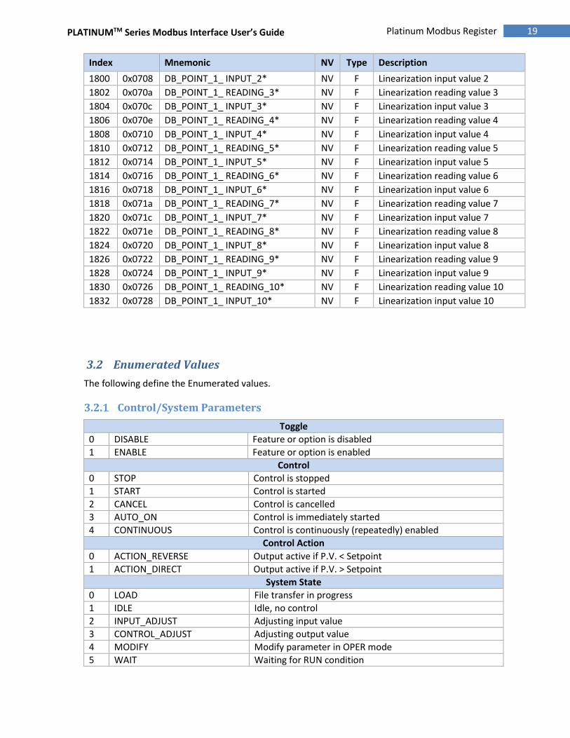
19 Platinum Modbus Register Assignments
Index Mnemonic NV Type Description
1800 0x0708 DB_POINT_1_ INPUT_2* NV F Linearization input value 2
1802 0x070a DB_POINT_1_ READING_3* NV F Linearization reading value 3
1804 0x070c DB_POINT_1_ INPUT_3* NV F Linearization input value 3
1806 0x070e DB_POINT_1_ READING_4* NV F Linearization reading value 4
1808 0x0710 DB_POINT_1_ INPUT_4* NV F Linearization input value 4
1810 0x0712 DB_POINT_1_ READING_5* NV F Linearization reading value 5
1812 0x0714 DB_POINT_1_ INPUT_5* NV F Linearization input value 5
1814 0x0716 DB_POINT_1_ READING_6* NV F Linearization reading value 6
1816 0x0718 DB_POINT_1_ INPUT_6* NV F Linearization input value 6
1818 0x071a DB_POINT_1_ READING_7* NV F Linearization reading value 7
1820 0x071c DB_POINT_1_ INPUT_7* NV F Linearization input value 7
1822 0x071e DB_POINT_1_ READING_8* NV F Linearization reading value 8
1824 0x0720 DB_POINT_1_ INPUT_8* NV F Linearization input value 8
1826 0x0722 DB_POINT_1_ READING_9* NV F Linearization reading value 9
1828 0x0724 DB_POINT_1_ INPUT_9* NV F Linearization input value 9
1830 0x0726 DB_POINT_1_ READING_10* NV F Linearization reading value 10
1832 0x0728 DB_POINT_1_ INPUT_10* NV F Linearization input value 10
3.2 Enumerated Values
The following define the Enumerated values.
Control/System Parameters
Toggle
0 DISABLE Feature or option is disabled
1 ENABLE Feature or option is enabled
Control
0 STOP Control is stopped
1 START Control is started
2 CANCEL Control is cancelled
3 AUTO_ON Control is immediately started
4 CONTINUOUS Control is continuously (repeatedly) enabled
Control Action
0 ACTION_REVERSE Output active if P.V. < Setpoint
1 ACTION_DIRECT Output active if P.V. > Setpoint
System State
0 LOAD File transfer in progress
1 IDLE Idle, no control
2 INPUT_ADJUST Adjusting input value
3 CONTROL_ADJUST Adjusting output value
4 MODIFY Modify parameter in OPER mode
5 WAIT Waiting for RUN condition

PLATINUMTM Series Modbus Interface User’s Guide
20 Platinum Modbus Register Assignments
6 RUN System is running
7 STANDBY Standby mode
8 STOP Stopped mode
9 PAUSE Paused mode
10 FAULT Fault detected
11 SHUTDOWN Shutdown condition detected
12 AUTOTUNE Autotune in progress
Display & Formatting
Time Format
0 MINUTE_SECOND MM.SS displayed
1 HOUR_MINUTE HH.MM displayed
2 MILLISECONDS S.MMM displayed
3 HOUR_MINUTE_SECONDS HH:MM:SS display (6 digit only)
Decimal Point
0 DECIMAL_POINT_NONE Display as XXXX
1 DECIMAL_POINT_3 Display as XXX.X
2 DECIMAL_POINT_2 Display as XX.XX
3 DECIMAL_POINT_1 Display as X.XXX
Units
0 UNIT_NONE No units applied
1 UNIT_CELCIUS Values converted to C
2 UNIT_FARENHEIT Values converted to F
Color
0 COLOR_OFF No color
1 COLOR_GREEN GREEN
2 COLOR_RED RED
3 COLOR_AMBER AMBER
4 COLOR_NO_CHANGE Do not change color (internal use)
Brightness
0 BRIGHTNESS_LOW 33% duty cycle
1 BRIGHTNESS_MEDIUM 66% duty cycle
2 BRIGHTNESS_HIGH 100% duty cycle
Ramp and Soak Parameters
Ramp & Soak State (bit mapped)
0x00 INACTIVE Ramp & Soak is inactive
0x01 RAMPING Ramp time and RE bit set
0x02 SOAKING Soak time and SE bit set
0x04 RAMP_ACTIVE Ramp time
0x08 SOAK_ACTIVE Soak time
0x10 RAMP_SOAK_PAUSED Ramp & Soak is in PAUSE condition
0x80 RAMP_SOAK_ERROR Ramp & Soak error condition

PLATINUMTM Series Modbus Interface User’s Guide
21 Platinum Modbus Register Assignments
Ramp & Soak Tracking
0 FIXED_RAMP Fixed RAMP time
1 FIXED_SOAK Fixed SOAK time
2 FIXED_CYCLE Fixed CYCLE time
Ramp & Soak Link Action
0 STOP_PROCESS Stop at end of profile
1 HOLD_PROCESS Hold last SOAK level at end of profile
2 LINK_PROFILE Link to Profile defined in LINK field
Ramp & Soak Control
0 RAMP_SOAK_DISABLED Disabled
1 RAMP_SOAK_ENABLED Enabled by RUN button
2 RAMP_SOAK_REMOTE Enabled by RUN button or Digital Input
Input Parameters
Sensor Type
0 SENSOR_TC Thermocouple
1 SENSOR_RTD RTD
2 SENSOR_PROCESS Process Input
3 SENSOR_THERMISTOR Thermistor
4 SENSOR_REMOTE Remote
Thermocouple Types
0 J 6 R
1 K 7 S
2 T 8 B
3 E 9 C
4 N 10 <RESERVED>
5 <RESEREVED> 11 <RESERVED>
RTD ACRV OHM Types
0 385_100 385 Curve, 100 ohms
1 385_500 385 Curve, 500 ohms
2 385_1000 385 Curve, 1000 ohms
3 392_100 392 Curve, 100 ohms
4 3916_100 3916Curve, 100 ohms
RTD Wire types
0 2_WIRE
1 3_WIRE
2 4_WIRE
Thermistor Type
0 THERMISTOR_2_25_K 2.25 K
1 THERMISTOR_5_K 5K
2 THERMISTOR_10_K 10K
Process Input Types
0 PROCESS_4_20 4 – 20 mA
1 PROCESS_0_24 0 – 24 mA
2 PROCESS_0_10 0 – 10 Vdc (No Support)

PLATINUMTM Series Modbus Interface User’s Guide
22 Platinum Modbus Register Assignments
3 PROCESS_0_1 0 – 1.0 Vdc (No Support)
2 PROCESS_0_POINT_1 0 – 0.1 Vdc (No Support)
5 PROCESS_PLUS_MINUS_10 +/– 10 Vdc – Single Ended Only
6 PROCESS_PLUS_MINUS_1 +/ – 1.0 Vdc – Single Ended, Diff, Ratiometric
7 PROCESS_PLUS_MINUS_POINT_1 +/ – 0.1 Vdc – Singled Ended, Diff., Ratiometric
8 PROCESS_PLUS_MINUS_POINT_05 +/ – 0.05 Vdc – Differential, Ratiometric only
Process Type
0 Single Ended Single Ended Inputs, +/- 10, +/- 1.0 and +/- 0.1 only
1 Differential Differential inputs, +/- 1.0, +/- 0.1 and +/- 0.05 only
2 Ratiometric Ratiometric inputs, +/- 1.0, +/- 0.1 and +/- 0.05 only
Range \ Type Single Ended Differential Ratiometric
+/- 10 Vdc X
+/- 1.0 Vdc X X X
+/- 0.1 Vdc X X X
+/- 0.05 Vdc X X
Process Live_Manual mode
0 LIVE_MODE
1 MANUAL_MODE
Input Filtering
0 FILTER_CONSTANT_1 No filtering (1 X rate)
1 FILTER_CONSTANT_2 X 2 filtering
2 FILTER_CONSTANT_4 X 4 filtering
3 FILTER_CONSTANT_8 X 8 filtering
4 FILTER_CONSTANT_16 X 16 filtering
5 FILTER_CONSTANT_32 X 32 filtering
6 FILTER_CONSTANT_64 X 64 filtering
7 FILTER_CONSTANT_128 X 128 filtering
Setpoint Parameters
Setpoint Modes
0 SETPOINT_ABSOLUTE Setpoint value given as fixed constant
1 SETPOINT_DEVIATION Setpoint value is deviation (+/-) Setpoint 1 value
2 SETPOINT_REMOTE Setpoint 1 set by Remote Setpoint
3 SETPOINT_EXTERNAL Setpoint value set externally
4 SETPOINT_RAMP_SOAK Setpoint value set by Ramp & Soak process
Alarm Parameters
Alarm Mode
0 ALARM_ABSOLUTE Alarm setpoint is fixed constant
1 ALARM_DEVIATION_1 Alarm is offset from Setpoint 1
2 ALARM_DEVIATION_2 Alarm is offset from Setpoint 2
Alarm Type
0 ALARM_DISABLED Alarm not active
1 ALARM_ABOVE Alarm triggered if PV > ALM.H

PLATINUMTM Series Modbus Interface User’s Guide
23 Platinum Modbus Register Assignments
2 ALARM_BELOW Alarm trigger if PV < ALM.L
3 ALARM_HI_LO Alarm trigger if PV > ALM.H or PV < ALM.L
4 ALARM_BAND Alarm trigger if PV > ALM.L and PV < ALM.H
Alarm Latch Control
0 ALARM_UNLATCH Alarm does not latch
1 ALARM_LATCH Alarm state will be latched, clear by front panel
2 ALARM_LATCH_REMOTE Alarm state will be latched, clear by digital input
3 ALARM_HI_LO Alarm state latched, clear by front panel or input
Output Parameters
Output Types
0x00 OUTPUT_NONE No output available
0x01 OUTPUT_STR Single Poll Relay
0x02 OUTPUT_SSR SSR output
0x04 OUTPUT_DTR Double Poll Relay
0x08 OUTPUT_DCP DC Pulse output
0x10 OUTPUT_ANG Analog Output
0x20 OUTPUT_IANG Isolated Analog Output
0x40 OUTPUT_IDC Isolated DC Pulse Output
Output Polarity
0 NORMALLY_OPEN Contacts OPEN until activated
1 NORMALLY_CLOSED Contacts CLOSED until activated
Output Type
0 VOLTAGE Voltage range
1 CURRENT Current range
Output Mode
0 OUTPUT_OFF Output maintained in OFF state
1 OUTPUT_PID Output control by PID control function
2 OUTPUT_ON_OFF Output controlled by ON-OFF control function
3 OUTPUT_RETRANSMISSION Output retransmits the scaled process variable
4 OUTPUT_ALARM_1 Output set by ALARM 1 state
5 OUTPUT_ALARM_2 Output set by ALARM 2 state
6 OUTPUT_RAMP_EVENT Output set by Ramp & Soak RE.ON control bit
7 OUTPUT_SOAK_EVENT Output set by Ramp & Soak SE.ON control bit
Output Process Range
0 OUTPUT_0_10 0-10 Vdc
1 OUTPUT_0_5 0-5 Vdc
2 OUTPUT_0_20 0-20 mA
3 OUTPUT_4-20 4-20 mA
4 OUTPUT_0_24 0-24 mA
Annunciator Parameters
Annunciator Mode
0 ANNUN_NONE Disable Annunciator
1 ANNUN_ALARM_1 Annunciator activated by Alarm 1
2 ANNUN_ALARM_2 Annunciator activated by Alarm 2

PLATINUMTM Series Modbus Interface User’s Guide
24 Platinum Modbus Register Assignments
3 ANNUN_OUTPUT_1 Annunciator activated by Output 1
4 ANNUN_OUTPUT_2 Annunciator activated by Output 2
5 ANNUN_OUTPUT_3 Annunciator activated by Output 3
6 ANNUN_OUTPUT_4 Annunciator activated by Output 4
6 ANNUN_RE_ON Annunciator activated by RE.ON bit
8 ANNUN_SE_ON Annunciator activated by SE.ON bit
9 ANNUN_RAMP_ACTIVE Annunciator activated during any RAMP cycle
10 ANNUN_SOAK_ACTIVE Annunciator activated during any SOAK cycle
Communication Parameters
Protocol
0 PROTOCOL_OMEGA Omega Protocol
1 PROTOCOL_MODBUS Modbus Protocol
Data Flow (Omega Protocol)
0 DATA_FLOW_COMMAND Interactive command mode
1 DATA_FLOW_CONTINUOUS Continuous mode
Separation Character (Omega Protocol)
0 SEPARATION_SPACE Use <space> character between records
1 SEPARATION_CR Use <CR> between records
Modbus Protocol (Modbus Protocol)
0 MODBUS_RTU ASCII formatted records
1 MODBUS_ASCII RTU formatted records
2 MODBUS_PDU PDU formatted records
Serial Mode
0 SERIAL_RS232
1 SERIAL_RS485
Serial Baud Rate
0 BAUD_300
1 BAUD_600
2 BAUD_1200
3 BAUD_2400
4 BAUD_4800
5 BAUD_9600
6 BAUD_19200
7 BAUD_38400
8 BAUD_57600
9 BAUD_115200
Parity
0 PARITY_NONE
1 PARITY_ODD
2 PARITY_EVEN
Data Bits
0 BITS_7
1 BITS_8

PLATINUMTM Series Modbus Interface User’s Guide
25 Platinum Modbus Register Assignments
Excitation Parameters
Excitation
0 EXCITATION_0_VOLTS
1 EXCITATION_5_VOLTS
2 EXCITATION_10_VOLTS
3 EXCITATION_12_VOLTS
4 EXCITATION_24_VOLTS
Calibration Parameters
Calibration Mode
0 CAL_NONE
1 CAL_1_POINT
2 CAL_2_POINT
3 CAL_ICE_POINT

PLATINUMTM Series Modbus Interface User’s Guide
26 Platinum Modbus Register Assignments
Input / Output Scaling
Scaling operations allow translating source (input) signals to scaled output signal using a linear
translation defined by a SLOPE (or gain) and an OFFSET. As shown below, (X1,Y1) and (X2,Y2) define
two points on a line that has a certain SLOPE and OFFSET. Knowing the SLOPE and OFFSET allows
determining the OUTPUT value for any given INPUT value using the equation:
Output = Input X SLOPE + OFFSET, where
GAIN = (Y2 - Y1) / (X2 - X1)
OFFSET = Y1 - (GAIN * X1).
Figure 1 I/O Scaling.
If (X2 - X1) == 0, the GAIN is set to 1 and the OFFSET is set to 0.
0
1
2
3
4
5
6
7
-1 0 1 2
INPUT VALUE
SLOPE
OFFSET
X
KNOWN/MEASURED INPUT VALUE
X
Equivalent
Engineering Units
X

M5458/0716