cnc 60 series custom release...
TRANSCRIPT
CNC
PROGRAMMING MANUAL
BNP-B2217E(ENG)
60 SeriesCUSTOM RELEASE (APLC)

Introduction
This manual explains the programming carried out when developing software with C-language in the M60/M60S Series custom release system. Read this manual thoroughly before starting development. All functions of the M60/M60S Series custom release system are described in this manual. However, there may be limits to the functions that can be used due to the option configuration. Check the CNC specifications before starting. The following manuals are available as reference. Refer to them as required.
Custom Release (APLC) Library Manual ..............................BNP-B2219 PLC Programming Manual (Personal computer) ..................BNP-B2215 PLC Programming Manual (Ladder) .....................................BNP-B2212 PLC Onboard Instruction Manual..........................................BNP-B2213 PLC Interface Manual ...........................................................BNP-B2211 DDB Interface Manual...........................................................BNP-B2214
Precautions for using this material This manual is written for persons having an understanding of C language. An effort has been made to describe special handling, however, if the item is not described in this manual, please interpret it as "not possible".
Contents I. Outline 1. System Configuration ................................................................................................................1 1.1 General Configuration.......................................................................................................1 1.2 Outline of Release System ...............................................................................................2 1.3 Outline of Functions..........................................................................................................3 1.4 Keyboard Specifications ...................................................................................................4 1.5 Screen Specifications .......................................................................................................5 2. Software Configuration..............................................................................................................6 2.1 Outline Software Configuration Diagram ..........................................................................6 2.2 Custom Release Related CNC System Software .............................................................7 2.3 Custom Software ..............................................................................................................7 2.4 Task Configuration............................................................................................................8 3. Development Procedure............................................................................................................9 3.1 Development Flow ............................................................................................................9 3.2 Outline of Development Procedure.................................................................................10 4. Memory Specifications ............................................................................................................11 4.1 Custom Memory Specifications ......................................................................................11 4.2 Configuration of Custom ROM Area ...............................................................................12 5. List of Custom Release Library Functions...............................................................................13 5.1 Screen Display Function I/F............................................................................................13 5.1.1 Custom Screen Control Functions .......................................................................13 5.1.2 Display Request Functions ..................................................................................13 5.1.3 Graphic Display Request Functions.....................................................................13 5.1.4 Screen Display Auxiliary Functions......................................................................14 5.2 DDB I/F ...........................................................................................................................15 5.2.1 CNC Data Read/Write Functions .........................................................................15 5.3 Machine Control I/F ........................................................................................................16 5.3.1 PLC Device Access .............................................................................................16 5.3.2 PLC Device High-speed Access ..........................................................................16 5.4 File Release I/F...............................................................................................................17 5.4.1 File Data Input/Output Functions .........................................................................17 5.5 General Functions ..........................................................................................................17 5.5.1 Data Conversion Functions..................................................................................17
II. Programming 1. Before Starting Programming....................................................................................................1 1.1 Preparation for Development............................................................................................1 1.2 Installation of Compiler .....................................................................................................2 2. Designing the Specifications .....................................................................................................3 2.1 General Design Procedures .............................................................................................3 2.2 Determining the Screen Specifications.............................................................................3 2.3 Determining the Data Specifications.................................................................................4 2.4 Designing the Specifications of Common Functions ........................................................4 2.5 Mechanism for Displaying Screen ....................................................................................5 3. Creation of M_OPE Data...........................................................................................................8 3.1 Creation of Entry Table.....................................................................................................8 3.2 Creation of the Global Variables.....................................................................................10
- i -
3.3 Selective Function Table mseltb ( ) .........................................................................12 3.4 Screen Decision Table menublk [ ].............................................................................14 3.5 Common Variables .........................................................................................................19 3.5.1 OCB Table (pcoptb.ocb.xxxx) ..............................................................................23 3.5.2 Setting Area Buffer (pcoptb.settei.xxxx)...............................................................25 3.5.3 Setting Area Control Information (pcoptb.kcbtblr.xxxx)........................................26 4. Creation of M_OPE Functions.................................................................................................28 4.1 Power-on-time Initialize Function mopeini () ..............................................................29 4.2 F0 Key Screen Initialize Function mf0ini ().................................................................30 4.3 Key Input Pre-process Function mkeyin () .................................................................31 4.4 Selective Functions ms () ..........................................................................31 4.5 Screen Functions mf () ..........................................................................32 4.6 Key Input Post-process Function mkeycal () ..............................................................33 4.7 Always Called Function malway () .............................................................................34 4.8 Creation of the PLC Functions........................................................................................35 4.9 Flow of Each Function ....................................................................................................36 4.10 Selective Function Sample Program ............................................................................37 5. Debugging ...............................................................................................................................41 5.1 Loading Modules into the APLC Cassette ......................................................................41 5.2 Releasing the CNC Screen.............................................................................................44 5.3 When APLC is not Executed ..........................................................................................44 5.4 Measures during System Failure (System Down)...........................................................45 6. Precautions for Programming..................................................................................................46 6.1 Storage Class and Storage Area ....................................................................................47 6.2 Word Boundary...............................................................................................................48
III. Sample Programs 1. Development Procedure............................................................................................................1 2. Determining of Screen Specifications and Screen Transition ...................................................3 2.1 Determining the Screen Specifications.............................................................................3 2.2 Determining the Screen Transition ...................................................................................6 2.3 Defining the Global Data...................................................................................................7 3. Creation of the Setting Area Data ...........................................................................................10 4. Creation of M_OPE Selective Function Address Table and M_OPE Selective Functions ....................................................................................................12 4.1 Creation of M_OPE Selective Function Address Table ..................................................12 4.2 Creation of M_OPE Selective Functions ........................................................................15 5. Creation of Screen Decision Table and M_OPE Screen Functions ........................................25 5.1 Creation of Screen Decision Table .................................................................................25 5.2 Creation of M_OPE Screen Functions............................................................................28 6. Creation of M_OPE Power-on-time Initialize Function and M_OPE F0 Key Initialize Function...........................................................................................36 6.1 Creation of M_OPE Power-on-time Initialize Function....................................................36 6.2 Creation of M_OPE F0 Key Initialize Function ...............................................................38 7. Creation of M_OPE Key Input Pre-process Functions and M_OPE Key Input Post-process Functions .............................................................................40 7.1 Creation of M_OPE Key Input Pre-process Function .....................................................40 7.2 Creation of M_OPE Key Input Post-process Function....................................................41 8. Creation of M_OPE Always Called Functions .........................................................................42
- ii -
IV. Appendix Appendix 1 Changes for MELDAS500 Series Custom Release (APLC) System.......................1 Appendix 2 Precautions for Using SRAM Cassette....................................................................1 2.1 Custom Memory Specifications ........................................................................................1 2.2 Configuration of Custom RAM Area..................................................................................2 2.3 Changing between ROM and RAM Operation..................................................................3 2.4 Precautions.......................................................................................................................3
- iii -

I. Outline

1. System Configuration 1.1 General Configuration
1. System Configuration 1.1 General Configuration CBUS#1
CBUS#2
M60
Set the APLC cassette in CBUS#1.
(HR415, HR437, HR455, HR477)
CNC control unit
Operation board
Debugging console
I – 1

1. System Configuration 1.2 Outline of Release System
1.2 Outline of Release System APLC (Advanced Programmable Logic Controller) Release System An original custom screen corresponding to one function select key (F0) can be configured. As this screen is independent from the other CNC standard screens, it is suitable for adding relatively small-scale original custom functions such as a simple interactive programming tool, setup support screen or machine maintenance support screen, etc. The APLC is called out periodically as an independent task in the CNC. ����������������������������������������������������������������������������������������������
������������������������������������������������������������������������������������������������������������������������������������������������������������������������������������������������������������������������������������������������������������������������������������������
APLC release system
Machine control interface
DDB interface
F0 screen release interface
PLC function interface
File release interface
I – 2

1. System Configuration 1.3 Outline of Functions
1.3 Outline of Functions The custom release system is configured of the following five interface functions. F0 screen
release interface
An original custom screen can be created in the F0 function screen.
Internal data
The NC internal data and variables, etc., can be read/written at a high speed using the direct data bus method.
Parameters Control variable, etc.
DDB interface
PLC device
Bit device X, Y, M Word device R, D
Each device (X, Y, M, R, D) in the PLC canbe accessed in the same manner as the PLC main process.
Machine control interface
Machining program
File release interface
The machining programs can be read/written using the CNC file system.
< Y10 > The C language modules (PLC functions) can be called with a CALL command from the PLC main process or high-speed process.
PLC function interface CALL Pxx
I – 3

1. System Configuration 1.4 Keyboard Specifications
1.4 Keyboard Specifications When the input key is to be judged in the M_OPE function, the start key type (int_typ) and start key code (int_key) in the common variable OCB table are referred to. Use the macro name defined in "i_def.h" at this time.
Page keys
Menu keys Reset key Cursor keys
Data correct keys
Input key (Calculate)
Shift key
Alphanumeric and symbol keys READY LED
Various keys Function select keys
MITSUBISHI
SFG EDIT MDI
MONI- TOR
TOOL PARAM
DIAGN IN/OUT
CB CAN
F0
9
S )
N B
G C
X U
Y V
Z W
F E
D L
H !
P I
Q J
R K
M (
T I
1 2 3
4 5 6
7 8
/
$
. , 0
SP EOB
]
– +
∗ =
#
DELETE INS
SHIFT
INPUT CALC RESET
?
READY
O A
I – 4

1. System Configuration 1.5 Screen Specifications
1.5 Screen Specifications The basic screen configurations of the setting and display unit are shown below.
40 characters or 80 characters
Graphic area
640 × 409
18 lines
Previous page key Next page key
Menu keys (five)
Screen display
No. of displayed characters: 40 (horizontal) × 18 (vertical) or 80 (horizontal) × 18 (vertical)
Setting area display (16th line) Running status display area (17th line) Menu display (18th line)
[Setting and display unit] Each screen display area and setting area has the following type of functions. • Screen display area ................... Display area for the screen created by the user. • Setting area ................................ Area used for echo-back of the input keys, etc., when setting data. • Running status display area ....... Area that displays messages, etc., corresponding to the running status. • Menu display area ...................... Area that displays the names of the valid menu keys.
I – 5
2. Software Configuration 2.1 Outline Software Configuration Diagram
I – 6
2. Software Configuration
2.1 Outline Software Configuration Diagram
������������������������������������������������������������������������������������������������������������������������������������������������������������������������������������������������������������������������������������������������������������������������������������������������������������������������������������������������������������������������������������������������������������������������������������������������������������������������������������������������������������������������������������������������������������������������������������������������������������������������������������������������������������������������������������������������������������������������������������������������������������������������������������������������������������������������������������������������������������������������������������������������������������������������������������������������������������������������������������������������������������������������������������������������������������������������������������������������������������������������������������������������������������������������������������������������������������������������������������������������������������������������������������������������������������������������������������������������������������������������������������������������������������������������������������������������������������������������������������������������������������������������������������������
����������������������������������������������������������������������������������������������������������������������������������������������������������������������������������������������������������������������������������������������������������������������������������������������������������������������������������������������������������������������������������������������������������������������������������������������������������������������������������������������������������������������������������������������������������������������������������������������������������������������������������������������������������������������������������������������������������������������������������������������������������������������������������������������������������������������������������������������������������������������������������������������������������������������������������������������������������������������������
Machine control
PLC control
OS
Screen process
Display process
Screen release I/F
File release I/F
DDB I/F
Machine control I/F
P_OPE
CNC release function interface
CNC library
Custom library
Custom support function
PLC function
M_OPE function group
M_OPE various data
PLC base process
High-speed process
Main process
User PLC
Custom release library
M_OPE (custom creation
software) CNC release function
CNC system
Custom ROM cassette
����������������������������������������������������������������������������������������������������������������������������������������������������������������������������������������������������������������������������������������������������������������������������������������������������������������������������������������������������������������������������������������������������������������������������������������������������������������������������������������������������������������������������������������������������������������������������������������������������������������������������������������������������������������������������������������������������������������������������������������������������������������������������������������������������������������������������������������������������������������������������������������������������������������������������������������������������������������������������������������������������������������������������������������������������������������������������������������
Parameters Control
variables, etc.
X, Y R, D
M, F, T
Machining program
NC internal data
Custom internal data
PLC device
RAM area for system (parameters, machining program, etc.) RAM area for custom (512 KB)
2. Software Configuration 2.2 Custom Release Related CNC System Software
2.2 Custom Release Related CNC System Software The following four custom release related software items are prepared. (1) Display process
The characters and graphics required from the screen process task or custom software are displayed and processed.
(2) Screen process
This task is used to control the CNC screen process and custom release. For the custom screen, the key data input to the custom software is transferred.
(3) PLC control task
This task is used to control the user PLC. The PLC is divided into three process levels, and the APLC release is realized mainly using base process 1. (The PLC functions are executed as main processes or high-speed processes.)
(4) CNC release function
This is a group of functions for releasing the CNC internal functions and data, etc., as various support for the custom software. From the custom software, these functions are accessed via the CNC library in the custom release library.
2.3 Custom Software The custom software is largely divided into the M_OPE and custom release library. (1) M_OPE
This is the generic name of the software created by the user. It is actually configured of a group of functions that carry out custom screen processing, screen display data and custom exclusive data, etc. The PLC functions called with the CALL command from the PLC main process are also included in this.
(2) Custom release library
This is software provided by Mitsubishi to support the user's software development. This library is largely divided into two groups. The first is used to access the CNC release functions called the CNC library. P_OPE is used in particular to control the screen transition related matters. The other is called the custom library, and is a group of processing functions such as numeric operation and data type conversion, etc. The actual library is located in the custom side.
I – 7

2. Software Configuration 2.4 Task Configuration
2.4 Task Configuration The custom release system software (task) is controlled by the same real-time multitask OS (hereafter OS) as the CNC. Legend
CNC standard task
Custom exclusive task
Custom software
OS
PLC high-speed process
Ladder sequence
PLC function (C language)
Machine control process 1
PLC main process Ladder sequence High
PLC function (C language)
Machine control process 2
Program analysis
Degree of priority
Display process CNC standard screen process
Screen process NC_OPE
P_OPE PLC base process Low
M_OPE
APLC screen release
I – 8
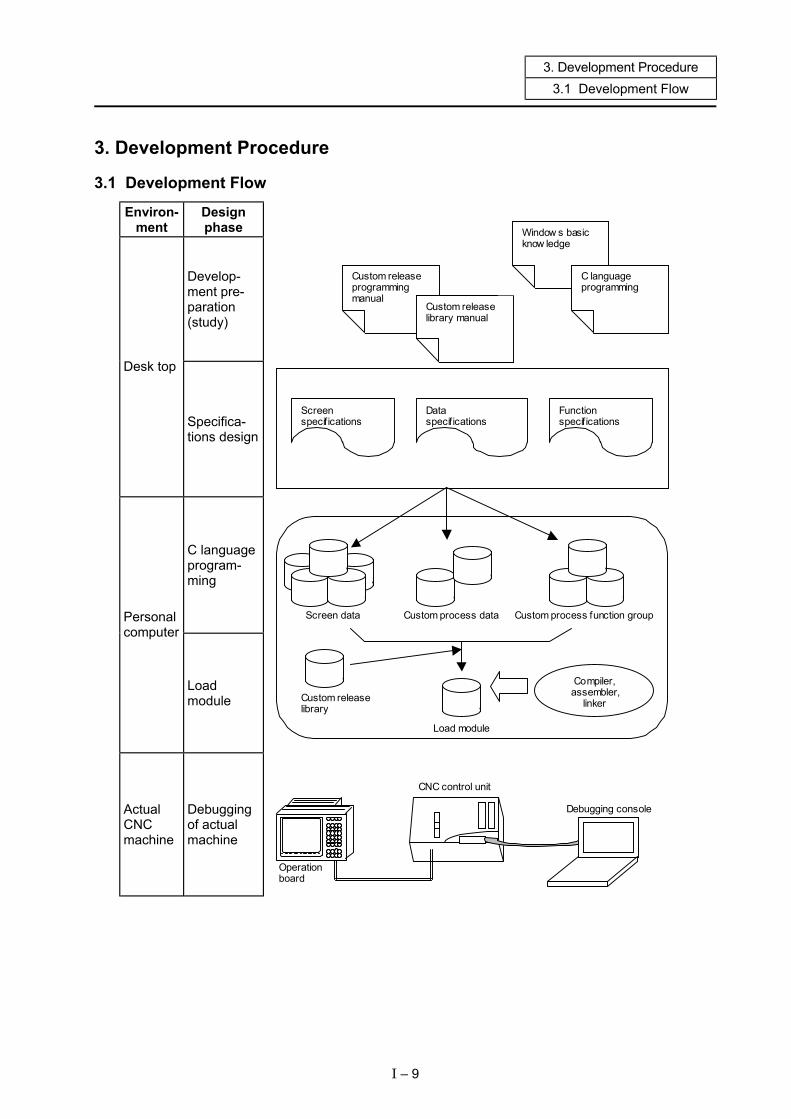
3. Development Procedure 3.1 Development Flow
3. Development Procedure
3.1 Development Flow
Custom release programming manual
Custom release library manual
Window s basic know ledge
C language programming
Screen specifications
Data specifications
Function specifications
Screen data Custom process data Custom process function group
Load module
Custom release library
Compiler, assembler,
linker
CNC control unit
Debugging console
Environ- ment
Design phase
Develop- ment pre- paration (study)
Desk top
Specifica- tions design
C language program- ming
Personal computer
Load module
Actual Debugging
Operation board
CNC machine
of actual machine
I – 9

3. Development Procedure 3.2 Outline of Development Procedure
3.2 Outline of Development Procedure (1) Preparation for development (only at first development)
Before developing a custom release function, it is necessary to understand the inner works of the custom release system, and to prepare a development environment, etc. An understanding of the OS (Windows), C language programming and compiler, etc., is required for software development, so study about these before starting.
(2) Design of specifications
The first step of development is to design the function specifications of the software (screen process, etc.) to be created. The items that should be considered for the screen specifications, etc., are as follow. • Screen transition specifications • Screen layout specifications • Screen operation specifications • Data specifications • External (PLC or macro program, etc.) interface specifications
(3) C language programming
The custom software processing section (function group) is programmed with C language using a text editor in the personal computer.
(4) Creation of load module
The C source file is complied and the load module (S-record format) is created using the "Green Hills Software, Inc. C Cross MIPS Compiler". The created load module is loaded into the CNC machine via RS-232C.
(5) Debugging of actual machine
The operation of the custom software is confirmed on the actual machine. If the debugging console is connected to the actual machine, simple debugging can be carried out using the debugger built into the CNC.
I – 10

4. Memory Specifications 4.1 Custom Memory Specifications
4. Memory Specifications
4.1 Custom Memory Specifications
ROM area APLC usage area Cassette type M60S Series M60 Series
RAM area
HR415/HR455 512KB 1.0MB 512KB HR437/HR/477 512KB 1.5MB 512KB
I – 11

4. Memory Specifications 4.2 Configuration of Custom ROM Area
4.2 Configuration of Custom ROM Area
������������������������������������������������������������������������������������������������������������������������������������������������������������������������������������������������������������������������������������������������������������������������������������������������������������������������������������������������������������������������������������������������������������������������������
$AC001000
$AC400000
User work area
$AC080000
$AC500000
Reserved for system
��������������������������������������������������������������������������������������������
is the entry table, and is used for setting the address information for calling or starting the C language module, etc.
������������������������������������������������������������������������������������������
RAM area
(512KB)
��������������������������������������������������������������������������������������������������������������������������������������������������������������������������������������������������������������������������������������������������������������������������������������������������������������������������������������������������������������������������������������������������������������������������������������������������������������������������������������������������������������������������������������������������������������������������������������������������������������������������������������������������������������������������������������������������������������������������������������������������������������������������������������������������������������������������������������������������������������������������������������������������������������������������������������������������������������������������������������������������������������������������������������������������������������������������������������������������������������������������������������������������������������������������������������������������������������������������������������������������������������������������������������������������������������������������������������������������������������������������������������������������������������������������������������������������������������������������������������������������������������������������������
User program area
ROM area
$AC580000
(1.0MB)
(M60 only)
(1.5MB)
(M60 only)
$AC480000
512KB (M60/M60S Series)
$AC000000
I – 12
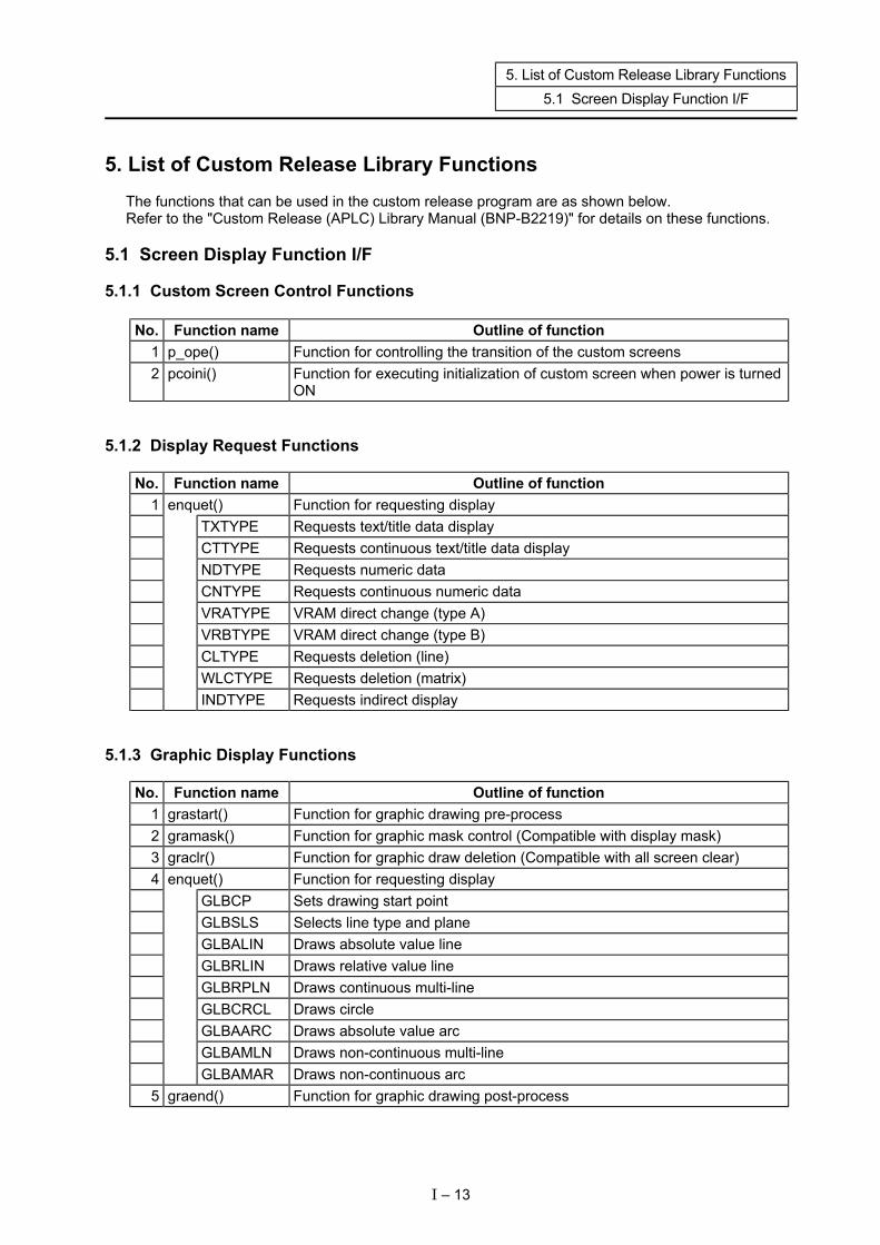
5. List of Custom Release Library Functions 5.1 Screen Display Function I/F
5. List of Custom Release Library Functions The functions that can be used in the custom release program are as shown below. Refer to the "Custom Release (APLC) Library Manual (BNP-B2219)" for details on these functions.
5.1 Screen Display Function I/F
5.1.1 Custom Screen Control Functions
No. Function name Outline of function 1 p_ope() Function for controlling the transition of the custom screens 2 pcoini() Function for executing initialization of custom screen when power is turned
ON
5.1.2 Display Request Functions
No. Function name Outline of function 1 enquet() Function for requesting display
TXTYPE Requests text/title data display CTTYPE Requests continuous text/title data display NDTYPE Requests numeric data CNTYPE Requests continuous numeric data VRATYPE VRAM direct change (type A) VRBTYPE VRAM direct change (type B) CLTYPE Requests deletion (line) WLCTYPE Requests deletion (matrix)
INDTYPE Requests indirect display
5.1.3 Graphic Display Functions
No. Function name Outline of function 1 grastart() Function for graphic drawing pre-process 2 gramask() Function for graphic mask control (Compatible with display mask) 3 graclr() Function for graphic draw deletion (Compatible with all screen clear) 4 enquet() Function for requesting display
GLBCP Sets drawing start point GLBSLS Selects line type and plane GLBALIN Draws absolute value line GLBRLIN Draws relative value line GLBRPLN Draws continuous multi-line GLBCRCL Draws circle GLBAARC Draws absolute value arc GLBAMLN Draws non-continuous multi-line
GLBAMAR Draws non-continuous arc 5 graend() Function for graphic drawing post-process
I – 13
5. List of Custom Release Library Functions 5.1 Screen Display Function I/F
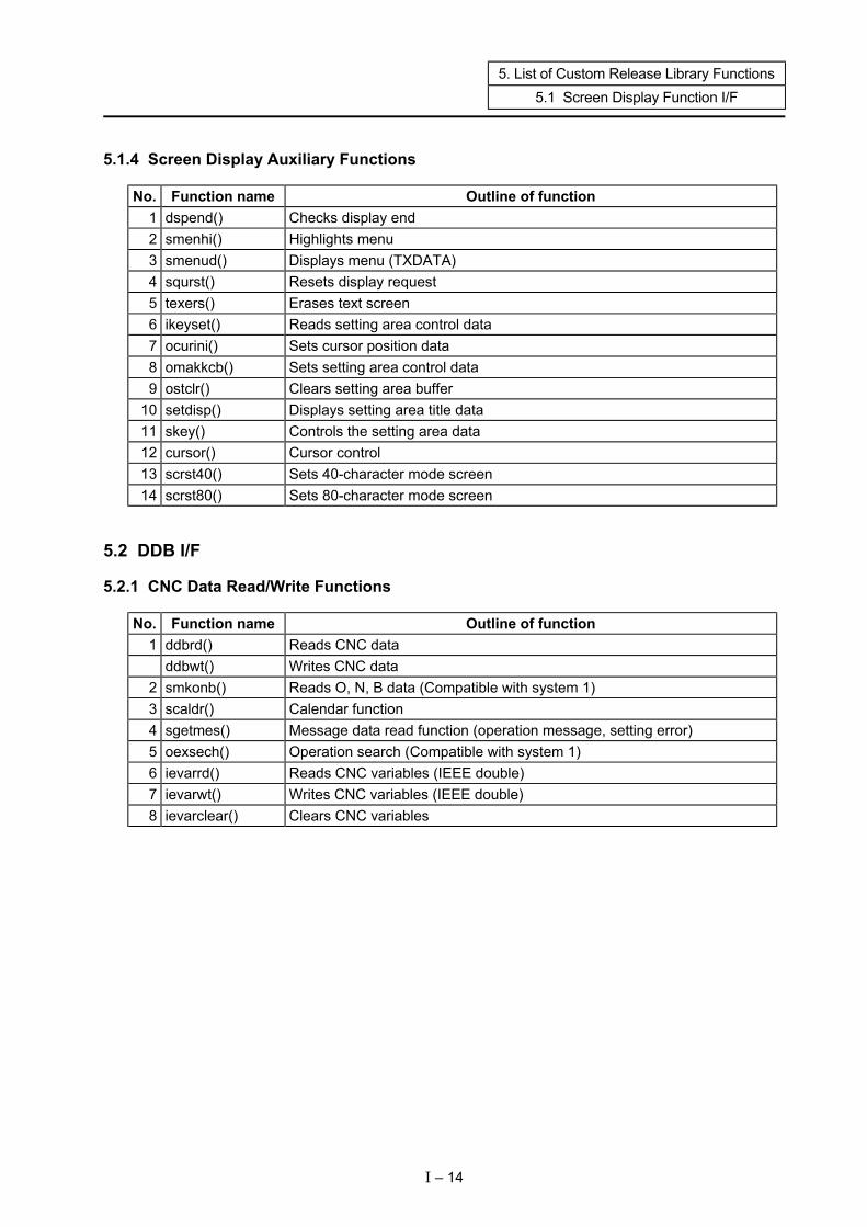
5.1.4 Screen Display Auxiliary Functions
No. Function name Outline of function 1 dspend() Checks display end 2 smenhi() Highlights menu 3 smenud() Displays menu (TXDATA) 4 squrst() Resets display request 5 texers() Erases text screen 6 ikeyset() Reads setting area control data 7 ocurini() Sets cursor position data 8 omakkcb() Sets setting area control data 9 ostclr() Clears setting area buffer
10 setdisp() Displays setting area title data 11 skey() Controls the setting area data 12 cursor() Cursor control 13 scrst40() Sets 40-character mode screen 14 scrst80() Sets 80-character mode screen
5.2 DDB I/F
5.2.1 CNC Data Read/Write Functions
No. Function name Outline of function 1 ddbrd() Reads CNC data
ddbwt() Writes CNC data 2 smkonb() Reads O, N, B data (Compatible with system 1) 3 scaldr() Calendar function 4 sgetmes() Message data read function (operation message, setting error) 5 oexsech() Operation search (Compatible with system 1) 6 ievarrd() Reads CNC variables (IEEE double) 7 ievarwt() Writes CNC variables (IEEE double) 8 ievarclear() Clears CNC variables
I – 14

5. List of Custom Release Library Functions 5.3 Machine Control I/F
5.3 Machine Control I/F
5.3.1 PLC Device Access
No. Function name Outline of function 1 set_ Sets the bit device 2 rst_ Resets the bit device 3 tst_ Tests the bit device 4 set_ Sets the word device 5 tst_ Tests the word device 6 lset_ Sets the long device 7 ltst_ Tests the long device
5.3.2 PLC Device High-speed Access
No. Function name Outline of function 1 melplcBset_ Sets the bit device 2 melplcBrst_ Resets the bit device 3 melplcBtst_ Tests the bit device 4 melplcWset_ Sets the word device 5 melplcWtst_ Tests the word device 6 melplcLset_ Sets the long device 7 melplcLtst_ Tests the long device
I – 15
5. List of Custom Release Library Functions 5.4 File Release I/F
5.4 File Release I/F
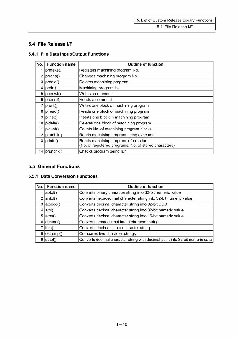
5.4.1 File Data Input/Output Functions
No. Function name Outline of function 1 prmake() Registers machining program No. 2 prrena() Changes machining program No. 3 prdele() Deletes machining program 4 prdir() Machining program list 5 prcmwt() Writes a comment 6 prcmrd() Reads a comment 7 plwrit() Writes one block of machining program 8 plread() Reads one block of machining program 9 plinst() Inserts one block in machining program
10 pldele() Deletes one block of machining program 11 plcunt() Counts No. of machining program blocks 12 plrunblk() Reads machining program being executed 13 prinfo() Reads machining program information
(No. of registered programs, No. of stored characters) 14 prunchk() Checks program being run
5.5 General Functions
5.5.1 Data Conversion Functions
No. Function name Outline of function 1 abtol() Converts binary character string into 32-bit numeric value 2 ahtol() Converts hexadecimal character string into 32-bit numeric value 3 atobcd() Converts decimal character string into 32-bit BCD 4 atol() Converts decimal character string into 32-bit numeric value 5 atos() Converts decimal character string into 16-bit numeric value 6 dchtoa() Converts hexadecimal into a character string 7 ltoa() Converts decimal into a character string 8 ostrcmp() Compares two character strings 9 satol() Converts decimal character string with decimal point into 32-bit numeric data
I – 16

II. Programming

1. Before Starting Programming 1.1 Preparation for Development
1. Before Starting Programming
1.1 Preparation for Development To develop the custom release system, the various hardware (development machine, etc.) and various software (C compiler, custom release library/tool) must be obtained and set up.
1.2 Installation of Compiler The "Green Hills Software, Inc. C Cross MIPS Compiler" is used. Refer to the "Green Hills Software, Inc. C Cross MIPS Compiler" installation procedures for details on the installation.
II – 1
2. Designing the Specifications 2.1 General Design Procedures
2. Designing the Specifications
2.1 General Design Procedures The custom screen is developed with the following procedure. (1) Determining the screen specifications (2) Determining the data specifications (3) Designing the specifications of the common functions (4) Creating the various M_OPE data (5) Creating the M_OPE screen display data (6) Creating the various M_OPE functions (7) Creating the load module (8) Debugging Steps (1) to (3), which are the specifications design level, will be described in the following section.
2.2 Determining the Screen Specifications First decide what types of functions each screen is to have. Example) Machine operation guidance display Machine information setting display Help screen when an alarm occurs Once the functions are decided, consider how each is to be realized, and decide the screen transition system, screen configuration and screen operation specifications. <Details of screen specifications> Screen name ................................. The screen name is set with four alphanumeric characters.
This name is used when defining the screen data and screen functions.
Screen layout................................. Decide where to lay what on the screen. Screen operation specifications .... Decide the key operation specifications. (Data setting method, etc.) Data specifications ........................ Clarify the data required for each screen.
The data that acts as an interface with other screens and functions is maintained as common data.
Screen transition specifications..... Decide how each screen is to be selected with the menu keys. These specifications are required when creating the screen decision table.
(Refer to the section "3.4 Screen Decision Table" in this chapter.)
II – 2
2. Designing the Specifications 2.3 Determining the Data Specifications
2.3 Determining the Data Specifications The data specifications are determined with the following type of procedure. (1) Clarify the data required for each screen, and arrange the results. (2) Classify the data required for each screen unit and the commonly required data. (3) Classify each data that can be initialized when the power is turned ON (that should be initialized),
and that cannot be initialized (parameters, etc.). (4) Arrange each data unit and create the data specifications. The data specifications decided with the above procedure are described in the global variables definition file "mglobal.c". (Refer to section "3.2 Creation of the Global Variables" in this chapter.)
2.4 Designing the Specifications of Common Functions Decide the common function specifications with the following type of procedure. (1) Clarify which functions are required on each screen. (2) Extract the functions that can be used commonly. (3) Reevaluate the extracted functions to find those that can be used as a common interface, and
decide the common function specifications. Of the common functions decided with the above procedure, the functions required when the screen is selected are described as selective functions in the selective function table "mseltb". Example) Screen delete function, menu display function, etc. (Refer to section "3.3 Selective Function Table" in this chapter.)
2.5 Mechanism for Displaying Screen The main function of the general C language is main(), but with the APLC screen release, the function p_ope() set in the entry table is the main function. The function p_ope() calls the M_OPE function created by the user with the following type of procedure. The process flow is shown on the following page.
II – 3
2. Designing the Specifications 2.5 Mechanism for Displaying Screen
Screen process flow (P_OPE)
(1) NO Is F0 screen valid?
YES (2) #6451/bit0 = 0 → Onboard is invalid #1222 (aux06)/bit2 = 0 → Waveform display is
invalid
Key data extraction function
(3) NO Has key been
input? YES
(4) Key pre-process
mkeyin()
(5) NO F0 key?
Screen decision table NO YES
Menu key? F0 initialization
mf0ini() menublk[] = {········}
YES Refer
Menu control function
(6) Selective function table
Selective function ms__()
Refer
(*mseltb[])() = {········}
(7) Refer Write Screen function
mf__() Refer
(8) NO OCB table Has key been
input? Key data Selective function Screen function address Menu block No.
YES
Key post-process mkeycal()
(9)
RAM Always called function malway()
End of screen process ........P_OPE function
....... M_OPE function
II – 4
2. Designing the Specifications 2.5 Mechanism for Displaying Screen
Explanation of screen process flow The M_OPE selective function or screen function is called by the P_OPE according to the screen decision table when the screen is changed. The actual screen setting and display are done using the various support functions (display request function enquet (), etc.) provided as libraries in the M_OPE selective function or screen function. (1) Whether the F0 screen is valid or not is judged with the following condition. • Bit 0 of the PLC parameter bit selection #6451 is OFF. (Refer to the section "5.2 Releasing the CNC Screen" for details on the bit selection screen.) (2) When the F0 screen is valid, the P_OPE key data extract function is called, the input key data is
extracted, and is set in the OCB table. (3) Whether a key was input or not is judged. If a key was input, steps (4) to (6) are executed. (4) When a key was input, the M_OPE key input pre-process function mkeyin() is called unconditionally. (5) After that the key data is judged. If the F0 key was input, the M_OPE F0 screen initialization function
mf0ini() is called, and if a menu key was input, the P_OPE menu control function is called. The OCB table selective function call flag and screen function address are set with these functions,
but in the P_OPE menu control function, this information is retrieved from the screen decision table (menublk).
(6) The M_OPE selective functions (ms__) in the selective function table (mseltb) corresponding to the
selective function call flag in the OCB table are called. The selective functions are called in order from the low-order bit of the selective function call flag.
(7) Next, the M_OPE screen function (mf__) set in the OCB table screen function address is called
regardless of whether a key is input or not. (8) When a key was input, the M_OPE key input post-process function mkeycal() is called unconditionally. (9) Finally, the M_OPE always called function malway() is called.
* When the basic specification parameter #1222 aux06 bit2 is ON (waveform display valid), the F0
release screen will not open even when the F0 key is pressed. However, the screen function (ms__()) and always called function (malway()) will be called. Note that even if a key is input, P_OPE will judge that data has not been input.
II – 5
3. Creation of M_OPE Data 3.1 Creation of Entry Table
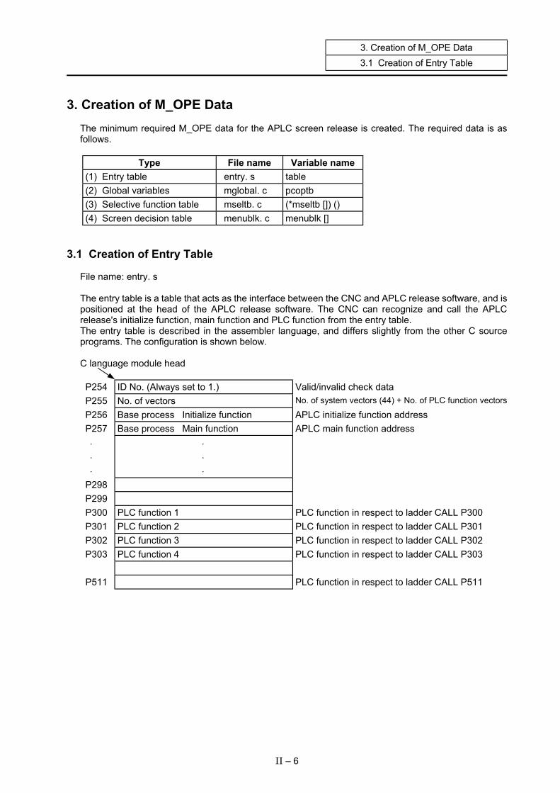
3. Creation of M_OPE Data The minimum required M_OPE data for the APLC screen release is created. The required data is as follows.
Type File name Variable name (1) Entry table entry. s table (2) Global variables mglobal. c pcoptb (3) Selective function table mseltb. c (*mseltb []) () (4) Screen decision table menublk. c menublk []
3.1 Creation of Entry Table File name: entry. s The entry table is a table that acts as the interface between the CNC and APLC release software, and is positioned at the head of the APLC release software. The CNC can recognize and call the APLC release's initialize function, main function and PLC function from the entry table. The entry table is described in the assembler language, and differs slightly from the other C source programs. The configuration is shown below. C language module head
P254 ID No. (Always set to 1.) Valid/invalid check data P255 No. of vectors No. of system vectors (44) + No. of PLC function vectors
P256 Base process Initialize function APLC initialize function address P257 Base process Main function APLC main function address ⋅ ⋅ ⋅
⋅ ⋅ ⋅
P298 P299 P300 PLC function 1 PLC function in respect to ladder CALL P300 P301 PLC function 2 PLC function in respect to ladder CALL P301 P302 PLC function 3 PLC function in respect to ladder CALL P302 P303 PLC function 4 PLC function in respect to ladder CALL P303 P511 PLC function in respect to ladder CALL P511
II – 6
3. Creation of M_OPE Data 3.1 Creation of Entry Table
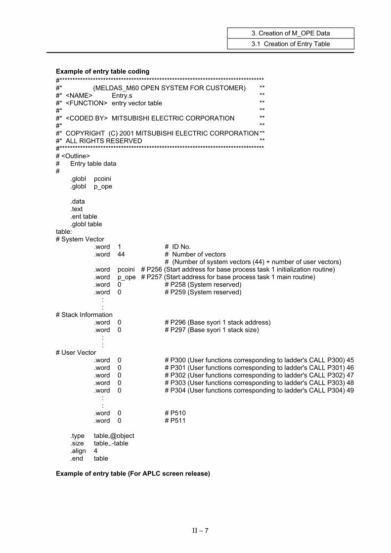
Example of entry table coding #******************************************************************************** #* (MELDAS_M60 OPEN SYSTEM FOR CUSTOMER) ** #* <NAME> Entry.s ** #* <FUNCTION> entry vector table ** #* ** #* <CODED BY> MITSUBISHI ELECTRIC CORPORATION ** #* ** #* COPYRIGHT (C) 2001 MITSUBISHI ELECTRIC CORPORATION ** #* ALL RIGHTS RESERVED ** #******************************************************************************** # <Outline> # Entry table data # .globl pcoini .globl p_ope .data .text .ent table .globl table table: # System Vector .word 1 # ID No. .word 44 # Number of vectors # (Number of system vectors (44) + number of user vectors) .word pcoini # P256 (Start address for base process task 1 initialization routine) .word p_ope # P257 (Start address for base process task 1 main routine) .word 0 # P258 (System reserved) .word 0 # P259 (System reserved) : : # Stack Information .word 0 # P296 (Base syori 1 stack address) .word 0 # P297 (Base syori 1 stack size) : : # User Vector .word 0 # P300 (User functions corresponding to ladder's CALL P300) 45 .word 0 # P301 (User functions corresponding to ladder's CALL P301) 46 .word 0 # P302 (User functions corresponding to ladder's CALL P302) 47 .word 0 # P303 (User functions corresponding to ladder's CALL P303) 48 .word 0 # P304 (User functions corresponding to ladder's CALL P304) 49 : : .word 0 # P510 .word 0 # P511 .type table,@object .size table,.-table .align 4 .end table Example of entry table (For APLC screen release)
II – 7
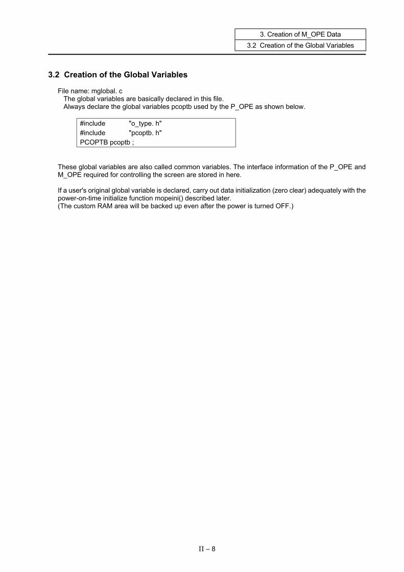
3. Creation of M_OPE Data 3.2 Creation of the Global Variables
3.2 Creation of the Global Variables File name: mglobal. c
The global variables are basically declared in this file. Always declare the global variables pcoptb used by the P_OPE as shown below.
#include "o_type. h" #include "pcoptb. h" PCOPTB pcoptb ;
These global variables are also called common variables. The interface information of the P_OPE and M_OPE required for controlling the screen are stored in here. If a user's original global variable is declared, carry out data initialization (zero clear) adequately with the power-on-time initialize function mopeini() described later. (The custom RAM area will be backed up even after the power is turned OFF.)
II – 8

3. Creation of M_OPE Data 3.2 Creation of the Global Variables
Example of global variable declaration coding /*********************************************************************************/ /** (MELDAS_M60 OPEN SYSTEM FOR CUSTOMER) **/ /** <NAME> mglobal.c **/ /** <FUNCTION> mglobal data define **/ /** **/ /** <CODED BY> MITSUBISHI ELECTRIC CORPORATION **/ /** **/ /** COPYRIGHT (C) 2001 MITSUBISHI ELECTRIC CORPORATION **/ /** ALL RIGHTS RESERVED **/ /*********************************************************************************/ /* <Outline> Work area definition file used by user */ #include “o_type.h” #include “pcoptb.h” /**********************************/ /* External reference */ .**********************************/ /**/ PCOPTB pcoptb; /* Work area used by P_OPE */ char axis[3]; /* Work area used by user */ long value[100]; /* Work area used by user */
II – 9
3. Creation of M_OPE Data 3.3 Selective Function Table mseltb [ ]
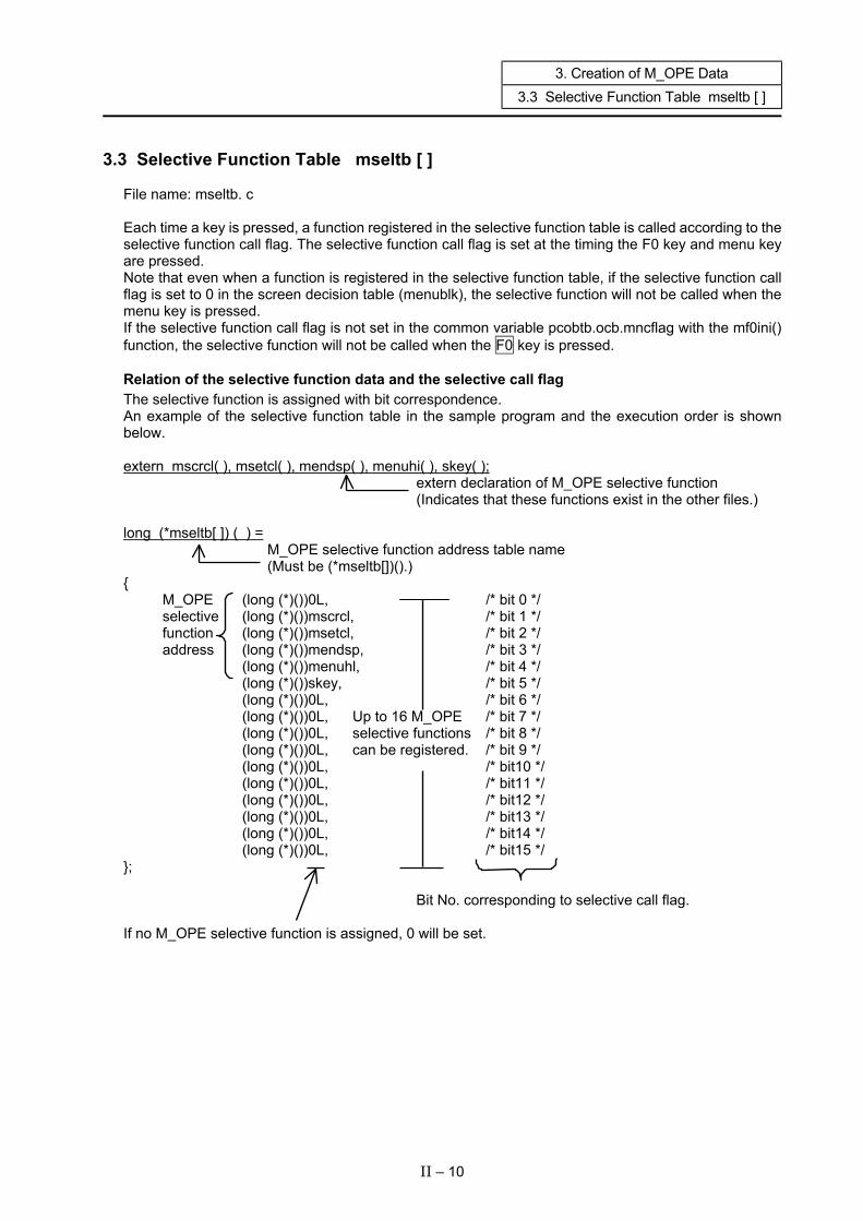
3.3 Selective Function Table mseltb [ ] File name: mseltb. c Each time a key is pressed, a function registered in the selective function table is called according to the selective function call flag. The selective function call flag is set at the timing the F0 key and menu key are pressed. Note that even when a function is registered in the selective function table, if the selective function call flag is set to 0 in the screen decision table (menublk), the selective function will not be called when the menu key is pressed. If the selective function call flag is not set in the common variable pcobtb.ocb.mncflag with the mf0ini() function, the selective function will not be called when the F0 key is pressed. Relation of the selective function data and the selective call flag The selective function is assigned with bit correspondence. An example of the selective function table in the sample program and the execution order is shown below. extern mscrcl( ), msetcl( ), mendsp( ), menuhi( ), skey( ); extern declaration of M_OPE selective function (Indicates that these functions exist in the other files.) long (*mseltb[ ]) ( ) =
M_OPE selective function address table name (Must be (*mseltb[])().)
{ M_OPE (long (*)())0L, /* bit 0 */ selective (long (*)())mscrcl, /* bit 1 */ function (long (*)())msetcl, /* bit 2 */ address (long (*)())mendsp, /* bit 3 */
(long (*)())menuhl, /* bit 4 */ (long (*)())skey, /* bit 5 */ (long (*)())0L, /* bit 6 */ (long (*)())0L, Up to 16 M_OPE /* bit 7 */ (long (*)())0L, selective functions /* bit 8 */ (long (*)())0L, can be registered. /* bit 9 */ (long (*)())0L, /* bit10 */ (long (*)())0L, /* bit11 */ (long (*)())0L, /* bit12 */ (long (*)())0L, /* bit13 */ (long (*)())0L, /* bit14 */ (long (*)())0L, /* bit15 */ }; Bit No. corresponding to selective call flag. If no M_OPE selective function is assigned, 0 will be set.
II – 10
3. Creation of M_OPE Data 3.3 Selective Function Table mseltb [ ]
II – 11
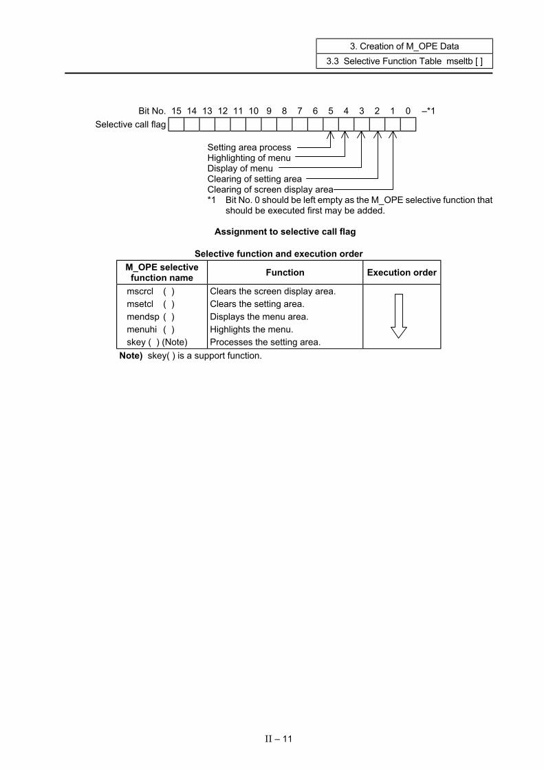
Bit No. 15 14 13 12 11 10 9 8 7 6 5 4 3 2 1 0 –*1
Selective call flag
Setting area process Highlighting of menu Display of menu Clearing of setting area Clearing of screen display area *1 Bit No. 0 should be left empty as the M_OPE selective function that
should be executed first may be added.
Assignment to selective call flag
Selective function and execution order M_OPE selective
function name Function Execution order
mscrcl ( ) msetcl ( ) mendsp ( ) menuhi ( ) skey ( ) (Note)
Clears the screen display area. Clears the setting area. Displays the menu area. Highlights the menu. Processes the setting area.
Note) skey( ) is a support function.

3. Creation of M_OPE Data 3.4 Screen Decision Table menublk [ ]
3.4 Screen Decision Table menublk [ ] File name: menublk. c If screen functions are registered in this table, the P_OPE can call the screen function. If the selective call flag is registered, the selective function can be called. The feature of this table is that the screen transition method when the menu key is pressed can be easily determined by how the table is created. The ideology is shown below.
Image of screen decision table (When there are five menu keys)
Menu 1 Menu 2 Menu 3 Menu 4 Menu 5 Selective call flag (1) Screen function address (2)
NEXT Menu block No. (3)
Custom flag (Not used) (4)
Menu block No.
0
1
2
•
•
•
(1) Selective call flag Which selective function to call is defined. When set to 0, nothing will be called. Define this flag with a bit correspondence. (Refer to section "3.3 Selective Function Table" for details.) (2) Screen function address Set the screen function address. Input -1 here if a screen function is not to be called. (3) NEXT menu block No. This is used when the screen is nested by pressing menu key. Input -1 here when nesting is not carried out. (4) Custom flag This data is not used. Set it to 0.
II – 12
3. Creation of M_OPE Data 3.4 Screen Decision Table menublk [ ]
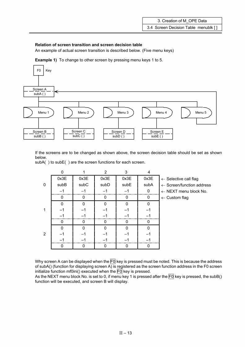
Relation of screen transition and screen decision table An example of actual screen transition is described below. (Five menu keys) Example 1) To change to other screen by pressing menu keys 1 to 5.
F0 Key
Screen A subA ( )
Menu 1 Menu 2 Menu 3 Menu 4 Menu 5
Screen B subB ( )
Screen C subC ( )
Screen D subD ( )
Screen E subE ( )
If the screens are to be changed as shown above, the screen decision table should be set as shown below. subA( ) to subE( ) are the screen functions for each screen.
0 1 2 3 4 0x3E 0x3E 0x3E 0x3E 0x3E ← Selective call flag
0 subB subC subD subE subA ← Screen/function address –1 –1 –1 –1 0 ← NEXT menu block No. 0 0 0 0 0 ← Custom flag 0 0 0 0 0
1 –1 –1 –1 –1 –1 –1 –1 –1 –1 –1 0 0 0 0 0 0 0 0 0 0
2 –1 –1 –1 –1 –1 –1 –1 –1 –1 –1 0 0 0 0 0
Why screen A can be displayed when the F0 key is pressed must be noted. This is because the address of subA() (function for displaying screen A) is registered as the screen function address in the F0 screen initialize function mf0ini() executed when the F0 key is pressed. As the NEXT menu block No. is set to 0, if menu key 1 is pressed after the F0 key is pressed, the subB() function will be executed, and screen B will display.
II – 13
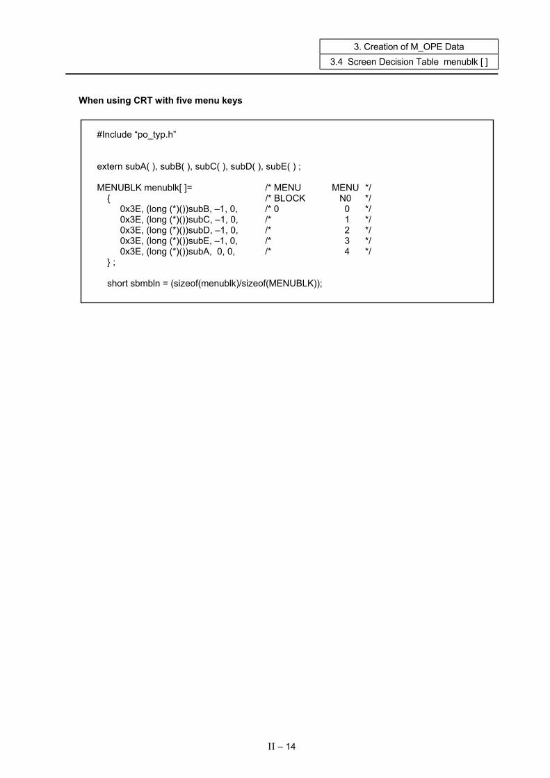
3. Creation of M_OPE Data 3.4 Screen Decision Table menublk [ ]
When using CRT with five menu keys
#Include “po_typ.h” extern subA( ), subB( ), subC( ), subD( ), subE( ) ; MENUBLK menublk[ ]= /* MENU MENU */ { /* BLOCK N0 */ 0x3E, (long (*)())subB, –1, 0, /* 0 0 */ 0x3E, (long (*)())subC, –1, 0, /* 1 */ 0x3E, (long (*)())subD, –1, 0, /* 2 */ 0x3E, (long (*)())subE, –1, 0, /* 3 */ 0x3E, (long (*)())subA, 0, 0, /* 4 */ } ; short sbmbln = (sizeof(menublk)/sizeof(MENUBLK));
II – 14
3. Creation of M_OPE Data 3.4 Screen Decision Table menublk [ ]
II – 15
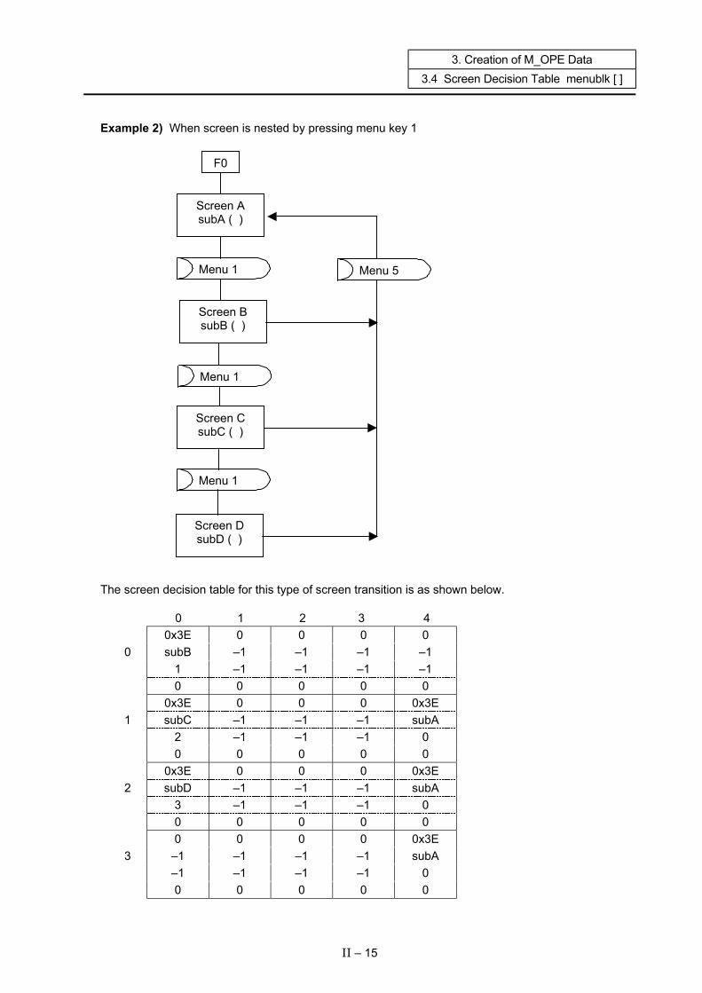
Example 2) When screen is nested by pressing menu key 1 F0
Screen A subA ( )
Menu 1 Menu 5 Screen B
subB ( ) Menu 1 Screen C
subC ( )
Menu 1
Screen D subD ( )
The screen decision table for this type of screen transition is as shown below.
0 1 2 3 4 0x3E 0 0 0 0
0 subB –1 –1 –1 –1 1 –1 –1 –1 –1 0 0 0 0 0 0x3E 0 0 0 0x3E
1 subC –1 –1 –1 subA 2 –1 –1 –1 0 0 0 0 0 0 0x3E 0 0 0 0x3E
2 subD –1 –1 –1 subA 3 –1 –1 –1 0 0 0 0 0 0 0 0 0 0 0x3E
3 –1 –1 –1 –1 subA –1 –1 –1 –1 0 0 0 0 0 0
3. Creation of M_OPE Data 3.4 Screen Decision Table menublk [ ]
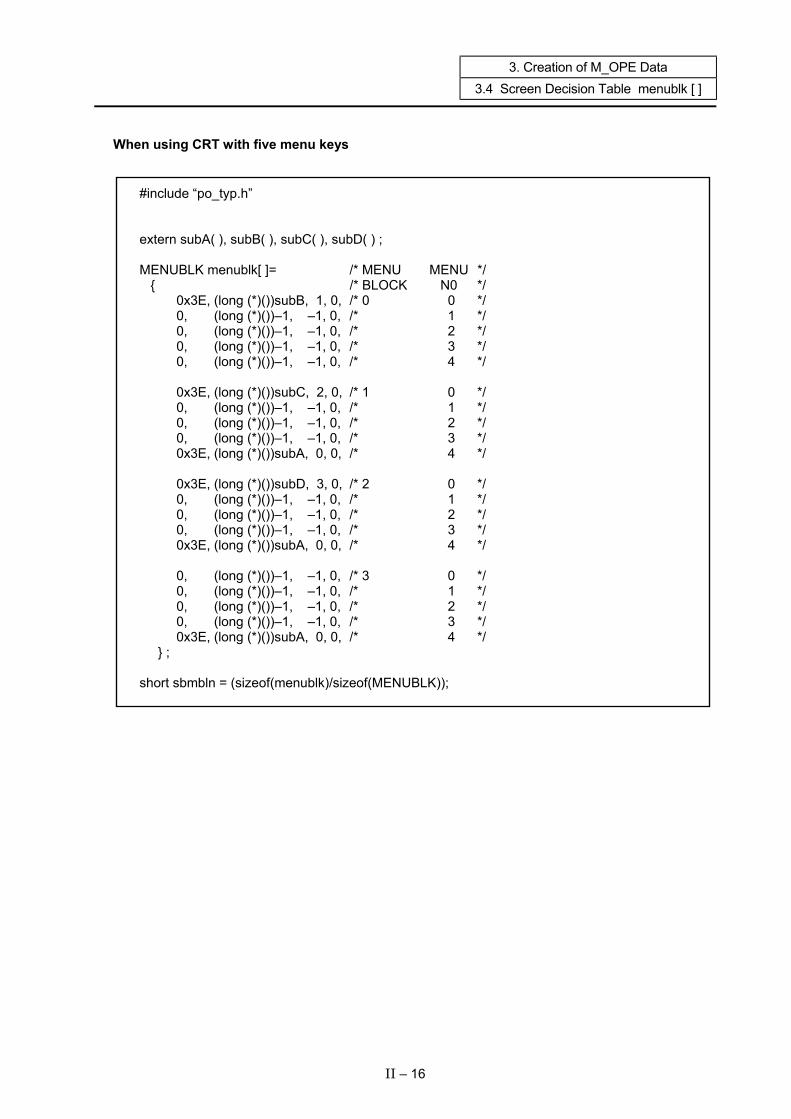
When using CRT with five menu keys
#include “po_typ.h” extern subA( ), subB( ), subC( ), subD( ) ; MENUBLK menublk[ ]= /* MENU MENU */ { /* BLOCK N0 */ 0x3E, (long (*)())subB, 1, 0, /* 0 0 */ 0, (long (*)())–1, –1, 0, /* 1 */ 0, (long (*)())–1, –1, 0, /* 2 */ 0, (long (*)())–1, –1, 0, /* 3 */ 0, (long (*)())–1, –1, 0, /* 4 */ 0x3E, (long (*)())subC, 2, 0, /* 1 0 */ 0, (long (*)())–1, –1, 0, /* 1 */ 0, (long (*)())–1, –1, 0, /* 2 */ 0, (long (*)())–1, –1, 0, /* 3 */ 0x3E, (long (*)())subA, 0, 0, /* 4 */ 0x3E, (long (*)())subD, 3, 0, /* 2 0 */ 0, (long (*)())–1, –1, 0, /* 1 */ 0, (long (*)())–1, –1, 0, /* 2 */ 0, (long (*)())–1, –1, 0, /* 3 */ 0x3E, (long (*)())subA, 0, 0, /* 4 */ 0, (long (*)())–1, –1, 0, /* 3 0 */ 0, (long (*)())–1, –1, 0, /* 1 */ 0, (long (*)())–1, –1, 0, /* 2 */ 0, (long (*)())–1, –1, 0, /* 3 */ 0x3E, (long (*)())subA, 0, 0, /* 4 */ } ; short sbmbln = (sizeof(menublk)/sizeof(MENUBLK));
II – 16

3. Creation of M_OPE Data 3.5 Common Variables
3.5 Common Variables
The common variables used to exchange data between P_OPE ⇔ M_OPE ⇔ support functions are listed below. typedef struct /* Operation Control Block table */ { long scrnumb; /* CNC screen number */ long (*mnfuncp)(); /* Screen function address */ unsigned short mncflag; /* Selective call flag */ short mnblno; /* NEXT menu block number */ char int_typ; /* Input key type */ char int_key; /* Input key code */ char setmode; /* Setting mode */ /* 0: Add */ /* 1: Insert */ /* 2: Replace */ char scr_if ; /* screen transition infomation */ short menuno; /* master screen menu number */ char funcno; /* master screen function number */ char pageno; /* master screen page number */ short subblk; /* sub menu block number */ char submen; /* sub menu number */ char subflg; /* next sub screen flag */ char modflg; /* 40-character or 80-character mode flag */ unsigned char pcount; /* p_ope call counter */ unsigned short posts1; /* p_ope control status */ long scrback; /* screen back number (Master) */ unsigned short cstmflg; /* sub screen table free data */ unsigned short scrchg; /* screen change flag */ /* bit0 : OFF no change */ /* : ON change */ /* bitF : OFF sub-menu back up */ /* : ON not back up */ char ocbdmy1[12]; /* dummy */ short tcflag; /* trace & check flag memo */ char initflg; /* init flag */ char ocbdmy2[13]; /* dummy */ char ocbdumy[192]; /* dummy */ }OCB;
II – 17

3. Creation of M_OPE Data 3.5 Common Variables
typedef struct /* Setting area buffer table */ { char dvar0[32]; /* setting area #0 (ASCII) */ char dvar1[32]; /* setting area #1 (ASCII) */ char dvar2[32]; /* setting area #2 (ASCII) */ char dvar3[32]; /* setting area #3 (ASCII) */ char dvar4[32]; /* setting area #4 (ASCII) */ char dvar5[32]; /* setting area #5 (ASCII) */ char dvar6[32]; /* setting area #6 (ASCII) */ char dvar7[32]; /* setting area #7 (ASCII) */ char dvar8[32]; /* setting area #8 (ASCII) */ char dvar9[32]; /* setting area #9 (ASCII) */ char dvar10[32]; /* setting area #10(ASCII) */ char dvar11[32]; /* setting area #11(ASCII) */ char dvar12[32]; /* setting area #12(ASCII) */ char dvar13[32]; /* setting area #13(ASCII) */ char dvar14[32]; /* setting area #14(ASCII) */ char dvar15[32]; /* setting area #15(ASCII) */ char dvar16[32]; /* setting area #16(ASCII) */ char dvar17[32]; /* setting area #17(ASCII) */ char dvar18[32]; /* setting area #18(ASCII) */ char dvar19[32]; /* setting area #19(ASCII) */ char dvar20[32]; /* setting area #20(ASCII) */ char dvar21[32]; /* setting area #21(ASCII) */ char dvar22[32]; /* setting area #22(ASCII) */ char dvar23[32]; /* setting area #23(ASCII) */ char dvar24[32]; /* setting area #24(ASCII) */ char dvar25[32]; /* setting area #25(ASCII) */ char dvar26[32]; /* setting area #26(ASCII) */ char dvar27[32]; /* setting area #27(ASCII) */ char dvar28[32]; /* setting area #28(ASCII) */ char dvar29[32]; /* setting area #29(ASCII) */ char dvar30[32]; /* setting area #30(ASCII) */ char dvar31[32]; /* setting area #31(ASCII) */ }SETTEI; typedef struct /* Setting area information table */ { char set_num; /* Number of setting areas */ char cur_typ; /* cursor type */ short set_bit; /* Setting area character present flag (#0 to #15) */ short cursor; /* Cursor 1 position */ short cursor2; /* Cursor 2 position (not used) */ TXDATA *set_ptr; /* Setting area title TXDATA pointer */ char kcbdmy1[4]; /* dummy */ TXDATA *setbptr[32]; /* Setting area text TXDATA pointer */ short set_bit2; /* Setting area character present flag (#16 to #31) */ char dsp_typ; /* TXDATA/LXDATA display type */ /* 1 : LXDATA */ /* 0xff : TXDATA */ char set_dmy; /* */ char kcbdmy2[12]; /* dummy */ }KCBTBLR;
II – 18

3. Creation of M_OPE Data 3.5 Common Variables
typedef struct /* system reserve */ { char set; /* */ char mode; /* */ unsigned short cur1; /* */ unsigned short cur2; /* */ unsigned short tabno; /* */ }SKEY2; typedef struct /* graphic data */ { long clrdat[5]; /* clear data */ long maskpln; /* mask plane data */ char gradmy[16]; /* dummy */ }GRADAT; typedef struct /* CNC infomation table */ { char nctype; /* bit0: (on) lathe, (off) machining */
Used by the system
char sys_max; /* The largest system number currently controlled */ short ava_sys; /* available system no. (BIT) */ char menu_no; /* menu max no. */ char sys_no; /* Max. number of systems to be controlled. */ char cdummy1[10]; /* char size dummy */ char ax_max[16]; /* axis max no. / system */ char cdummy2[224]; /* char size dummy */ }NCINFO; typedef struct /* sub screen data back up */ { short psubbno; /* sub screen menu block no. */ char psubmno; /* sub screen menu no. */ char psubdmy; /* dummy */ }BACKUP; typedef struct { OCB ocb; /* pc_ope control block */ SETTEI settei; /* settei bu ASCII buff */ KCBTBLR kcbtblr; /* current kcb table */ SKEY2 d_type; /* skey2 work area */ char pcodmy1[48]; /* dummy */ GRADAT gradat; /* graphic data */ NCINFO ncinfo; /* parametar memo table */ BACKUP backup[BKUP]; /* backup screen information */ long *brnkpt ; /* brink data pointer */ char pcodmy2[124]; /* dummy */ }PCOPTB;
II – 19
3.5 Common Variables
3. Creation of M_OPE Data
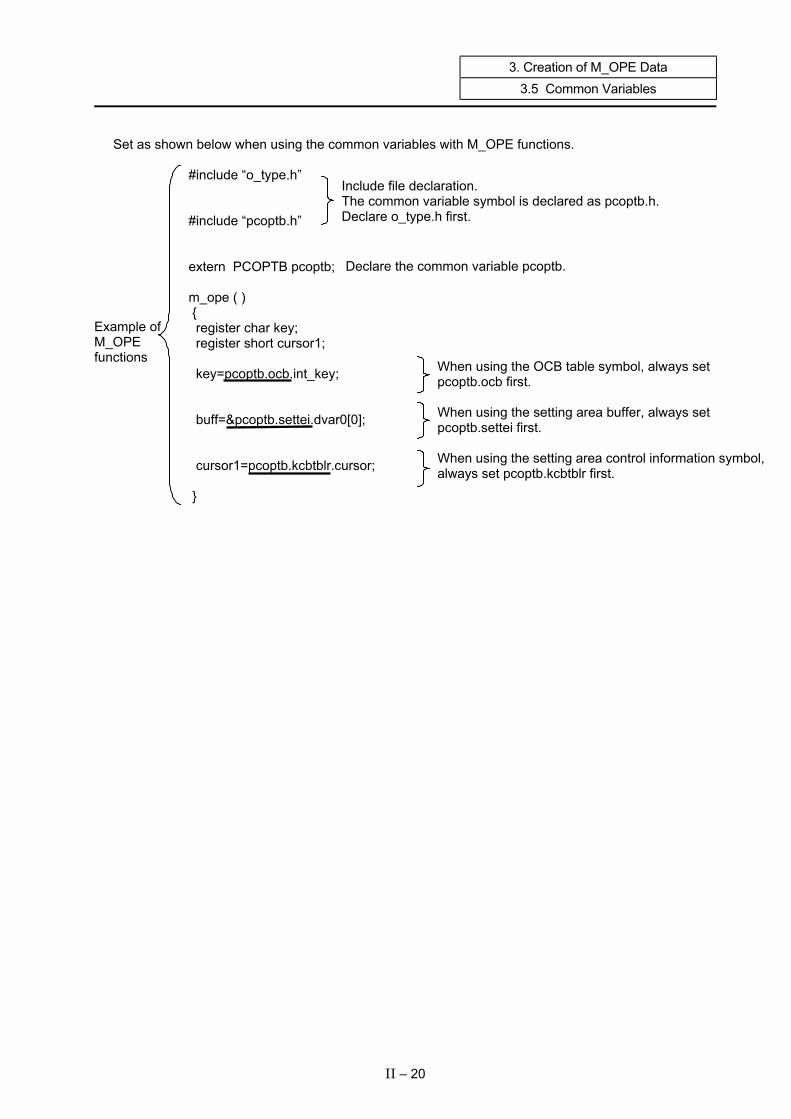
Set as shown below when using the common variables with M_OPE functions.
#include “o_type.h” Include file declaration. The common variable symbol is declared as pcoptb.h. Declare o_type.h first.
#include “pcoptb.h”
Declare the common variable pcoptb. extern PCOPTB pcoptb; m_ope ( ) {
Example of M_OPE functions
register char key; register short cursor1; When using the OCB table symbol, always set
pcoptb.ocb first. When using the setting area buffer, always set pcoptb.settei first. When using the setting area control information symbol,always set pcoptb.kcbtblr first.
key=pcoptb.ocb.int_key; buff=&pcoptb.settei.dvar0[0]; cursor1=pcoptb.kcbtblr.cursor; }
II – 20

3. Creation of M_OPE Data 3.5 Common Variables
The details of the data are explained below. Data that is not explained is used by the system.
3.5.1 OCB Table (pcoptb.ocb.xxxx) scrnumb CNC screen No. This is always required for the M-OPE function display request. Example) enque (pcoptb.ocb.scrnumb, TXTYPE, 0, abcd); (*mnfuncp) ( ) Screen/function address During P_OPE function menu control, the M_OPE screen/function address is
extracted from the screen/function decision table and set according to the current menu block No. and pressed menu No.
The M_OPE screen/function is called according to this address. mncflg Selective call flag During P_OPE function menu control, the selective call flag is extracted from the
screen/function decision table and set according to the current menu block No. and pressed menu No. The M_OPE selection function is executed according to this selective call flag.
After the menu key is pressed, if the M_OPE selective function is not to be executed until the menu key is pressed again, turn the M_OPE selective call flag OFF in the M_OPE selective function.
mnblno Menu block No. The menu control and menu display can be executed with the current menu block No.
using this data. When changing the menu block, the NEXT menu block No. in the screen/function
decision table is set to the next menu block. Int_typ Start key type Int_key Start key code The key type and key code extracted with the P_OPE function key data is set. If there is no key data, 0 (null character) is set.
Key type (int_typ) Key cord (int_key) Key Macro name Key Macro name
Function key FUNCT Function key 1 Function key 2 Function key 3 Function key 4 Function key 5
to Function key 20
FUNC1 FUNC2 FUNC3 FUNC4 FUNC5
to FUNC20
Menu key MENUT Menu key 1 Menu key 2 Menu key 3 Menu key 4 Menu key 5
MENU 1 MENU 2 MENU 3 MENU 4 MENU5
Previous page key PPAGET Next page key NPAGET
II – 21

3. Creation of M_OPE Data 3.5 Common Variables
Key type (int_typ) Key code (int_key)
Key Macro name Key Macro name Cursor movement keys
CURSRT ↑
↓
←
→
UP
DOWN
LEFT
RIGHT
Tab key TABT BTAB TAB
Data key (Alphanumeric, symbol)
DATAT There is no particular macro name. ASCII code is set for the key code.
BLANKT
DATAET
CLEART
DTDELT
DTINST
CBLOCKT
4 5
1 2
. 0 -
3
6
9 8 7
SHIFT = $
+ / *
Z K
Y J
X I
) ]
( [
W V U T S
R Q P O N
M L H G F
E D C B A
SP
INPUT
CAN
DELETE
INSERT
C·B
Include i_def.h when using the symbols above.
II – 22
3. Creation of M_OPE Data 3.5 Common Variables
setmode Setting mode This global variable is used with the setting area process support function skey ( ). This instructs whether to 0: Add, 1: Insert or 2: Replace the input key data in the setting
area buffer. The setting mode is changed using the cursor or by pressing the "INSERT" key
corresponding to the setting area text. menuno Menu No. The pressed menu No. is set. The menu No. is set with the P_OPE function menu control. When MENU1 is pressed 0 When MENU2 is pressed 1 When MENU5 is pressed 4
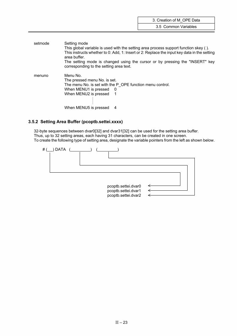
3.5.2 Setting Area Buffer (pcoptb.settei.xxxx) 32-byte sequences between dvar0[32] and dvar31[32] can be used for the setting area buffer. Thus, up to 32 setting areas, each having 31 characters, can be created in one screen. To create the following type of setting area, designate the variable pointers from the left as shown below.
# ( ) DATA ( ) ( )
pcoptb.settei.dvar0 pcoptb.settei.dvar1 pcoptb.settei.dvar2
II – 23

3. Creation of M_OPE Data 3.5 Common Variables
3.5.3 Setting Area Control Information (pcoptb.kcbtblr.xxxx) set_num Number of setting areas This is used when the support function processes the setting area. The number of setting areas is set with the support function omakkcb(). Set so that omakkcb() is called for the screen display when the menu is pressed with the
M_OPE screen/function. cur_typ Not used set_bit Setting character present flag (#0 to #15) If there is data in the setting area buffer when the "INPUT" key is pressed, the flag
corresponding to the setting area will be turned ON by the support function skey().
15 14 13 12 11 10 9 8 7 6 5 4 3 2 1 0 Setting
area buffer
d v a r 0
Data present
d v a r 15
cursor Cursor 1 position This is used when the support function processes the setting area. Set the cursor position to be displayed in the setting area. Set the last position of the setting area designated with the support function ocurini(). The cursor position can be moved and displayed with the support function skey() when ← → ← → are pressed. cursor2 Not used set_ptr Setting area title TXDATA pointer This is used when the support function processes the setting area. The setting area title TXDATA pointer is set with the support function omakkcb(). Set so that omakkcb() is called for the screen display when the menu is pressed with the
M_OPE screen/function. setbptr Setting area text TXDATA pointer This is used when the support function processes the setting area. The setting area text TXDATA pointer is set with the support function omakkcb(). Set so that omakkcb() is called for the screen display when the menu is pressed with the
M_OPE screen/function.
II – 24

3. Creation of M_OPE Data 3.5 Common Variables
set_bit2 Setting character present flag (#16 to #31) If there is data in the setting area buffer when the "INPUT" key is pressed, the flag
corresponding to the setting area will be turned ON by the support function skey().
15 14 13 12 11 10 9 8 7 6 5 4 3 2 1 0 Setting
area buffer
d v a r 16
Data present
d v a r 31
dsp_typ Not used
II – 25
4. Creation of M_OPE Functions
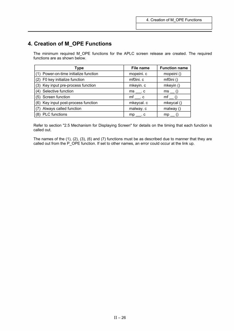
4. Creation of M_OPE Functions The minimum required M_OPE functions for the APLC screen release are created. The required functions are as shown below.
Type File name Function name (1) Power-on-time initialize function mopeini. c mopeini () (2) F0 key initialize function mf0ini. c mf0ini () (3) Key input pre-process function mkeyin. c mkeyin () (4) Selective function ms . c ms () (5) Screen function mf . c mf () (6) Key input post-process function mkeycal. c mkeycal () (7) Always called function malway. c malway () (8) PLC functions mp . c mp ()
Refer to section "2.5 Mechanism for Displaying Screen" for details on the timing that each function is called out. The names of the (1), (2), (3), (6) and (7) functions must be as described due to manner that they are called out from the P_OPE function. If set to other names, an error could occur at the link up.
II – 26
4. Creation of M_OPE Functions 4.1 Power-on-time Initialize Function mopeini ()
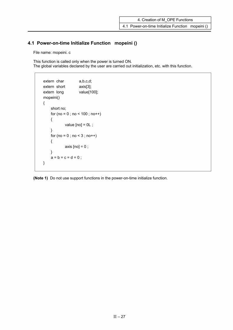
4.1 Power-on-time Initialize Function mopeini () File name: mopeini. c This function is called only when the power is turned ON. The global variables declared by the user are carried out initialization, etc. with this function.
extern char a,b,c,d; extern short axis[3]; extern long value[100]; mopeini() { short no; for (no = 0 ; no < 100 ; no++) { value [no] = 0L ; } for (no = 0 ; no < 3 ; no++) { axis [no] = 0 ; } a = b = c = d = 0 ; }
(Note 1) Do not use support functions in the power-on-time initialize function.
II – 27

4. Creation of M_OPE Functions 4.2 F0 Key Screen Initialize Function mf0ini ()
4.2 F0 Key Screen Initialize Function mf0ini () File name: mf0ini. c This function is called when the F0 key is pressed. Always initialize the following common variables (Note 1) in this function. pcoptb. ocb. mnfuncp. = Screen function address pcoptb. ocb. mncflag. = Selective function call flag pcoptb. ocb. mnblno. = Menu block No.
#include “o_type.h” #include “pcoptb.h” These must always be declared. extern PCOPTB pcopbt; extern sfinit( ); ] Name of function executed when F0 is pressed. • mf0ini( ) { pcoptb.ocb.mnfuncp = (long (*)())sfinit; Title screen function pcoptb.ocb.mncflag = 0xe; pcoptb.ocb.mnblno = 0; }
(Note 1) Refer to section "3.5 Common Variables" for details on variables.
II – 28
4. Creation of M_OPE Functions 4.3 Key Input Pre-process Function mkeyin ()
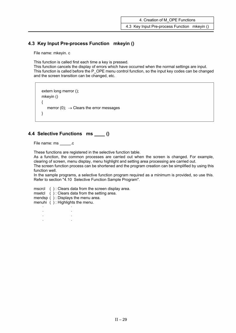
4.3 Key Input Pre-process Function mkeyin () File name: mkeyin. c This function is called first each time a key is pressed. This function cancels the display of errors which have occurred when the normal settings are input. This function is called before the P_OPE menu control function, so the input key codes can be changed and the screen transition can be changed, etc.
extern long merror (); mkeyin () { merror (0); → Clears the error messages }
4.4 Selective Functions ms () File name: ms .c These functions are registered in the selective function table. As a function, the common processes are carried out when the screen is changed. For example, clearing of screen, menu display, menu highlight and setting area processing are carried out. The screen function process can be shortened and the program creation can be simplified by using this function well. In the sample programs, a selective function program required as a minimum is provided, so use this. Refer to section "4.10 Selective Function Sample Program". mscrcl ( ) : Clears data from the screen display area. msetcl ( ) : Clears data from the setting area. mendsp ( ) : Displays the menu area. menuhi ( ) : Highlights the menu. · · · · · · · ·
II – 29
4. Creation of M_OPE Functions 4.5 Screen Functions mf ()
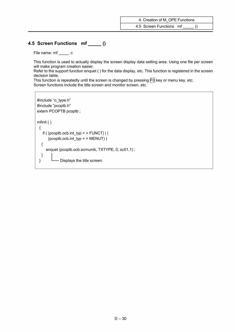
4.5 Screen Functions mf () File name: mf . c This function is used to actually display the screen display data setting area. Using one file per screen will make program creation easier. Refer to the support function enquet ( ) for the data display, etc. This function is registered in the screen decision table. This function is repeatedly until the screen is changed by pressing F0 key or menu key, etc. Screen functions include the title screen and monitor screen, etc.
#include “o_type.h” #include “pcoptb.h” extern PCOPTB pcoptb ; mfinit ( ) { if ( (pcoptb.ocb.int_typ = = FUNCT) | | (pcoptb.ocb.int_typ = = MENUT) ) { enquet (pcoptb.ocb.scrnumb, TXTYPE, 0, sc01,1) ; } } Displays the title screen.
II – 30

4. Creation of M_OPE Functions 4.6 Key Input Post-process Function mkeycal ()
4.6 Key Input Post-process Function mkeycal () File name: mkeycal. c This function is called after a screen function each time a key is pressed. This function displays the errors that occur when inputting normal settings.
extern long merror (); extern short errno ; mkeycal() { merror(errno); → Displays error messages }
(Note 1) With the M300 and M3/L3, this function was called before the screen process each time the
key was input. However, this has been changed as shown above. The M300 and M3/L3 mkeycal() function is realized with mkeyin() with the M500 and
M60/M60S Series.
II – 31
4. Creation of M_OPE Functions 4.7 Always Called Function malway ()
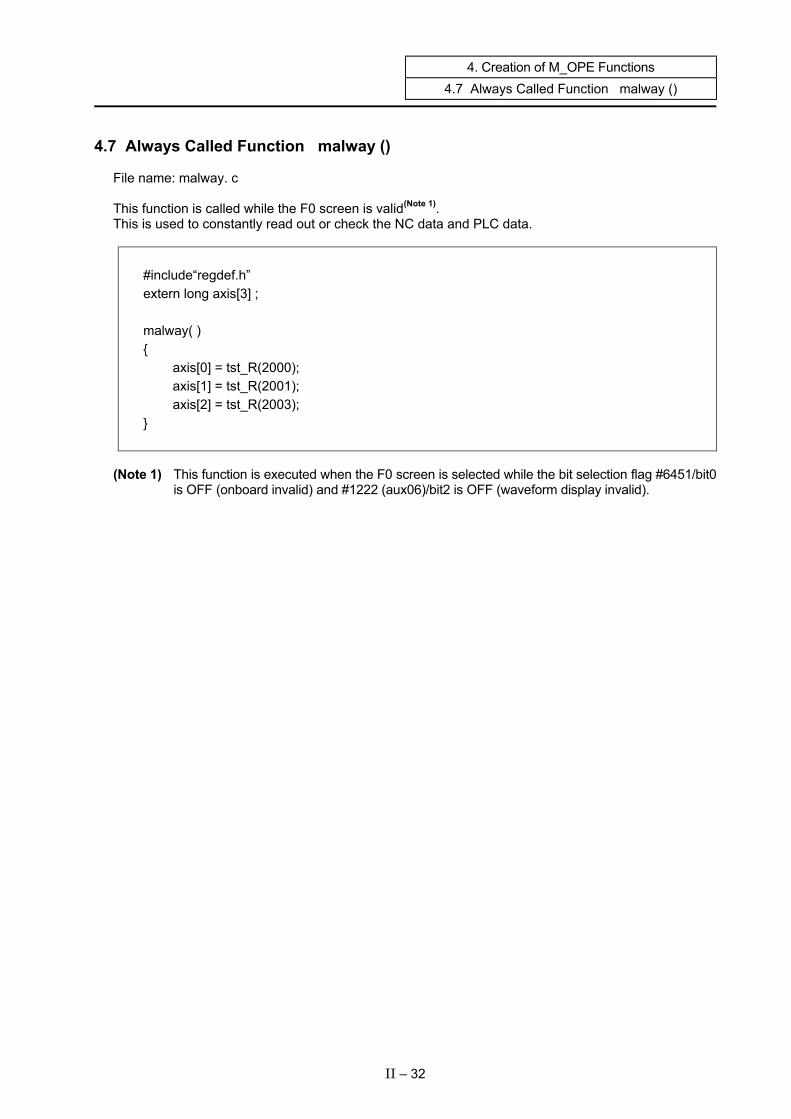
4.7 Always Called Function malway () File name: malway. c This function is called while the F0 screen is valid(Note 1). This is used to constantly read out or check the NC data and PLC data.
#include“regdef.h” extern long axis[3] ; malway( ) { axis[0] = tst_R(2000); axis[1] = tst_R(2001); axis[2] = tst_R(2003); }
(Note 1) This function is executed when the F0 screen is selected while the bit selection flag #6451/bit0
is OFF (onboard invalid) and #1222 (aux06)/bit2 is OFF (waveform display invalid).
II – 32
4. Creation of M_OPE Functions 4.8 Creation of the PLC Functions
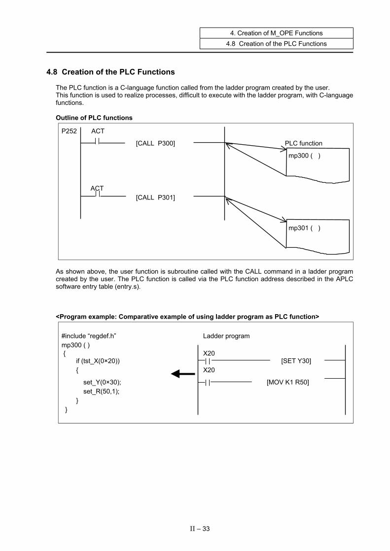
4.8 Creation of the PLC Functions The PLC function is a C-language function called from the ladder program created by the user. This function is used to realize processes, difficult to execute with the ladder program, with C-language functions. Outline of PLC functions
P252 ACT
[CALL P300] PLC function
mp300 ( )
ACT [CALL P301]
mp301 ( )
As shown above, the user function is subroutine called with the CALL command in a ladder program created by the user. The PLC function is called via the PLC function address described in the APLC software entry table (entry.s). <Program example: Comparative example of using ladder program as PLC function>
#include “regdef.h” Ladder program mp300 ( ) { X20 if (tst_X(0×20)) | | [SET Y30] { X20
set_Y(0×30); | | [MOV K1 R50] set_R(50,1); } }
II – 33

4. Creation of M_OPE Functions 4.9 Flow of Each Function
4.9 Flow of Each Function Take care to the flow of the process when creating the M_OPE functions just explained. (1) Basic flow of screen functions
END
START
Pre-process
Key?
Data setting process
Screen display process
Post-process
Menu key No
Input key
(2) Flow at branch point (Do not create a loop.) Poor example Good example
START START
a = 0? a = 0?
b = 0 b = 0
END END
Loops for a long time when conditions are not satisfied.
NO NO
II – 34

4. Creation of M_OPE Functions 4.10 Selective Function Sample Program
4.10 Selective Function Sample Program
<Erasing the screen display area> /********************************************************************************/ /* (MELDAS_M60 OPEN SYSTEM FOR CUSTOMER) */ /* <NAME> mscrcl.c */ /* <FUNCTION> m_ope Selective function (bit1) */ /* screen clear */ /* */ /* <CODED BY> MITSUBISHI ELECTRIC CORPORATION */ /* */ /* COPYRIGHT (C) 2001 MITSUBISHI ELECTRIC CORPORATION */ /* ALL RIGHTS RESERVED */ /********************************************************************************/ #include "o_type.h" #include "pcoptb.h" extern PCOPTB pcoptb; /* Common variable declaration */ mscrcl() { static short txclr4[] = { 1, 40*15, 0 }; /* Text (character) erase data */ static short txclr8[] = { 1, 80*15, 0 }; /* Text (character) erase data */ short *texclr ; if( pcoptb.ocb.modflg == 1 ) { texclr = txclr8 ; } else { texclr = txclr4 ; } gramask(1,0x0f); /* graphic mask */ texers(texclr); /* Erase text */ graclr(0x000F,0,0,640,409); /* gpaphic clrar */ cursor(pcoptb.ocb.scrnumb, 0xFE, 0, 0x8000, 0); /* Erase cursor 1 */ pcoptb.ocb.mncflag &= 0xFFFD; /* Selective call flag OFF (bit 1) */ }
II – 35

4. Creation of M_OPE Functions 4.10 Selective Function Sample Program
<Erasing the setting area> /********************************************************************************/ /* (MELDAS_M60 OPEN SYSTEM FOR CUSTOMER) */ /* <NAME> msetcl.c */ /* <FUNCTION> m_ope Selective function (bit2) */ /* Setting area clear */ /* */ /* <CODED BY> MITSUBISHI ELECTRIC CORPORATION */ /* */ /* COPYRIGHT (C) 2001 MITSUBISHI ELECTRIC CORPORATION */ /* ALL RIGHTS RESERVED */ /********************************************************************************/ #include "o_type.h" #include "pcoptb.h" extern PCOPTB pcoptb; /* Common variable declaration */ msetcl() { static short txclr4[] = { 40*16+1, 40*18, 0 }; /* Text (character) erase data */ static short txclr8[] = { 80*16+1, 80*18, 0 }; /* Text (character) erase data */ short *texclr ; if( pcoptb.ocb.modflg == 1 ) { texclr = txclr8 ; } else { texclr = txclr4 ; } texers(texclr); /* Erase text */ cursor(pcoptb.ocb.scrnumb, 0xFE, 0, 0x8000, 0); /* Erase cursor 1 */ pcoptb.ocb.mncflag &= 0xFFFB; /* Selective call flag OFF (bit 2) */ }
II – 36

4. Creation of M_OPE Functions 4.10 Selective Function Sample Program
<Displaying the menu area> /********************************************************************************/ /* (MELDAS_M60 OPEN SYSTEM FOR CUSTOMER) */ /* <NAME> mendsp.c */ /* <FUNCTION> m_ope Selective function (bit3) */ /* Menu display */ /* */ /* <CODED BY> MITSUBISHI ELECTRIC CORPORATION */ /* */ /* COPYRIGHT (C) 2001 MITSUBISHI ELECTRIC CORPORATION */ /* ALL RIGHTS RESERVED */ /********************************************************************************/ #include "c_def.h" #include "o_type.h" #include "pcoptb.h" extern PCOPTB pcoptb; /* Common variable declaration */ extern TXDATA men0[], men1[], men2[], men3[] ; /* Menu area display data declaration*/ mendsp() { static TXDATA *mnutx4[] = { men0, men1, men2 }; /* Menu display data address table */ static TXDATA *mnutx8[] = { men0, men3, men2 }; /* Menu display data address table */ static short mners4[] = { 40*16+1, 40*18, 0 }; /* Menu area erase data */ static short mners8[] = { 80*16+1, 80*18, 0 }; /* Menu area erase data */ TXDATA **menutx ; short *meners ; if( pcoptb.ocb.modflg == 1 ) { menutx = mnutx8 ; meners = mners8 ; } else { menutx = mnutx4 ; meners = mners4 ; } smenud(menutx, meners, pcoptb.ocb.mnblno); /* Menu display */ pcoptb.ocb.mncflag &= 0xFFF7; /* Selective call flag OFF (bit 3) */ }
II – 37

4. Creation of M_OPE Functions 4.10 Selective Function Sample Program
<Highlighting the menu> /********************************************************************************/ /* (MELDAS_M60 OPEN SYSTEM FOR CUSTOMER) */ /* <NAME> menuhi.c */ /* <FUNCTION> m_ope Selective function (bit4) */ /* Menu highlight */ /* */ /* <CODED BY> MITSUBISHI ELECTRIC CORPORATION */ /* */ /* COPYRIGHT (C) 2001 MITSUBISHI ELECTRIC CORPORATION */ /* ALL RIGHTS RESERVED */ /********************************************************************************/ #include "o_type.h" #include "pcoptb.h" extern PCOPTB pcoptb; /* Common variable declaration */ menuhi() { /* Menu highlight data */ static short mnatr41[] = { 40*17+ 1, 0x0400|8, –1 }; static short mnatr42[] = { 40*17+ 9, 0x0400|8, –1 }; static short mnatr43[] = { 40*17+17, 0x0400|8, –1 }; static short mnatr44[] = { 40*17+25, 0x0400|8, –1 }; static short mnatr45[] = { 40*17+33, 0x0400|8, –1 }; static short *mnatrp4[] = { /* Menu highlight data */ mnatr41, mnatr42, mnatr43, mnatr44, mnatr45}; /* Address table */ static short mnatr81[] = { 80*17+ 5, 0x0400|8, –1 }; static short mnatr82[] = { 80*17+21, 0x0400|8, –1 }; static short mnatr83[] = { 80*17+37, 0x0400|8, –1 }; static short mnatr84[] = { 80*17+53, 0x0400|8, –1 }; static short mnatr85[] = { 80*17+69, 0x0400|8, –1 }; static short *mnatrp8[] = { /* Menu highlight data */ mnatr81, mnatr82, mnatr83, mnatr84, mnatr85}; /* Address table */ short **menatrp ; if( pcoptb.ocb.modflg == 1 ) { menatrp = mnatrp8 ; } else { menatrp = mnatrp4 ; } smenhi(menatrp, pcoptb.ocb.submen); /* Menu highlight */ pcoptb.ocb.mncflag &= 0xFFEF; /* Selective call flag OFF (bit 4) */ }
II – 38

5. Debugging 5.1 Loading Modules into the APLC Cassette
5. Debugging
5.1 Loading Modules into the APLC Cassette (1) Outline
The APLC software loads the load modules into the APLC memory cassette from the CNC input screen. The load modules are loaded into the APLC memory cassette via RS-232C as an S-record format. Compare is executed during the loading.
[Hardware configuration] The configuration of the hardware for loading the APLC software load modules is shown below.
CD 1
DR 6
CBUS#1
CBUS#2
M60
HR211
DX35x/45x
Set the APLC memory cassette in CBUS#1. HR415/HR455 HR437/HR477
RS-232C cable
APLC software load module
(S-record format)
[RS-232C cable assignment] Use a shield cable and connect the shielded wire with the FG on the NC side. No connections are required on the personal computer side. The CD signal is not used and does not need to be connected. ER/DR and RS/CS may need to be short-circuited depending on the personal computer model.
* The personal computer and RS-232C cable must be prepared by the user.
CH1
CH2
CNC serial port (ch1 or ch2) The serial port set on the input screen is used.
PC COM port
PC
NC side (DSUB25Pin)
PC side (DSUB 9pin)
CF11
����������������������������������������������������������������������������������������
FG 9
SD 3 RD 2 RS 7
CS 8 ER 4
SG 5
1 FG
2 SD 3 RD 4 RS
5 CS 20 ER
6 DR 8 CD 7 SG
Shield
CD 8
DR 6
NC side (DSUB25Pin)
PC side (DSUB 25pin)
����������������������������������������������������������������������������������������
FG 1
SD 2 RD 3 RS 4
CS 5 ER 20
SG 7
1 FG
2 SD 3 RD 4 RS
5 CS 20 ER
6 DR 8 CD 7 SG
Shield
Refer to section"4.1 Custom Memory Specifications" in "1. Outline" for details on the applicable cassette.
II – 39
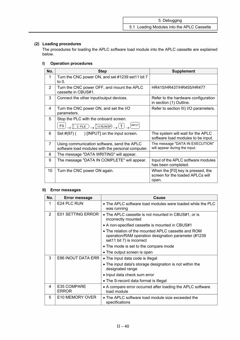
5. Debugging 5.1 Loading Modules into the APLC Cassette
(2) Loading procedures The procedures for loading the APLC software load module into the APLC cassette are explained below.
I) Operation procedures
No. Step Supplement 1 Turn the CNC power ON, and set #1239 set11 bit 7
to 0.
2 Turn the CNC power OFF, and mount the APLC cassette in CBUS#1.
HR415/HR437/HR455/HR477
3 Connect the other input/output devices. Refer to the hardware configuration in section (1) Outline.
4 Turn the CNC power ON, and set the I/O parameters.
Refer to section III) I/O parameters.
5 Stop the PLC with the onboard screen.
F0 → 3. FILE → 4.RUN/SP → 1 → INPUT
6 Set #(97) ( ) [INPUT] on the input screen. The system will wait for the APLC software load modules to be input.
7 Using communication software, send the APLC software load modules with the personal computer.
The message "DATA IN EXECUTION" will appear during the input.
8 The message "DATA WRITING" will appear. 9 The message "DATA IN COMPLETE" will appear. Input of the APLC software modules
has been completed. 10 Turn the CNC power ON again. When the [F0] key is pressed, the
screen for the loaded APLCs will open.
II) Error messages
No. Error message Cause 1 E24 PLC RUN • The APLC software load modules were loaded while the PLC
was running 2 E01 SETTING ERROR • The APLC cassette is not mounted in CBUS#1, or is
incorrectly mounted • A non-specified cassette is mounted in CBUS#1 • The relation of the mounted APLC cassette and ROM
operation/RAM operation designation parameter (#1239 set11 bit 7) is incorrect
• The mode is set to the compare mode • The output screen is open
3 E86 INOUT DATA ERR • The input data code is illegal • The input data's storage designation is not within the
designated range • Input data check sum error • The S-record data format is illegal
4 E35 COMPARE ERROR
• A compare error occurred after loading the APLC software load module
5 E10 MEMORY OVER • The APLC software load module size exceeded the specifications
II – 40
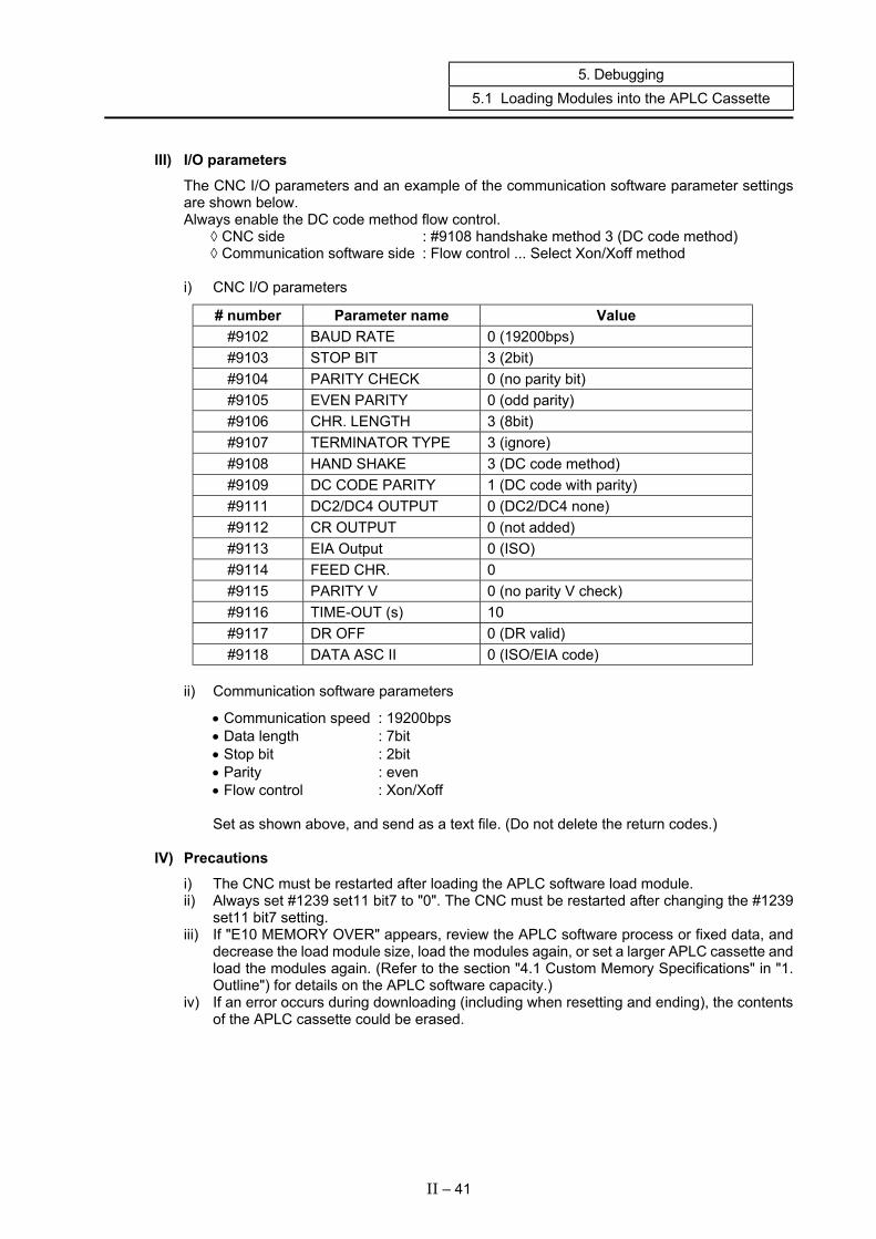
5. Debugging 5.1 Loading Modules into the APLC Cassette
III) I/O parameters The CNC I/O parameters and an example of the communication software parameter settings are shown below. Always enable the DC code method flow control. ◊ CNC side : #9108 handshake method 3 (DC code method) ◊ Communication software side : Flow control ... Select Xon/Xoff method i) CNC I/O parameters
# number Parameter name Value #9102 BAUD RATE 0 (19200bps) #9103 STOP BIT 3 (2bit) #9104 PARITY CHECK 0 (no parity bit) #9105 EVEN PARITY 0 (odd parity) #9106 CHR. LENGTH 3 (8bit) #9107 TERMINATOR TYPE 3 (ignore) #9108 HAND SHAKE 3 (DC code method) #9109 DC CODE PARITY 1 (DC code with parity) #9111 DC2/DC4 OUTPUT 0 (DC2/DC4 none) #9112 CR OUTPUT 0 (not added) #9113 EIA Output 0 (ISO) #9114 FEED CHR. 0 #9115 PARITY V 0 (no parity V check) #9116 TIME-OUT (s) 10 #9117 DR OFF 0 (DR valid) #9118 DATA ASC II 0 (ISO/EIA code)
ii) Communication software parameters
• Communication speed : 19200bps • Data length : 7bit • Stop bit : 2bit • Parity : even • Flow control : Xon/Xoff Set as shown above, and send as a text file. (Do not delete the return codes.)
IV) Precautions
i) The CNC must be restarted after loading the APLC software load module. ii) Always set #1239 set11 bit7 to "0". The CNC must be restarted after changing the #1239
set11 bit7 setting. iii) If "E10 MEMORY OVER" appears, review the APLC software process or fixed data, and
decrease the load module size, load the modules again, or set a larger APLC cassette and load the modules again. (Refer to the section "4.1 Custom Memory Specifications" in "1. Outline") for details on the APLC software capacity.)
iv) If an error occurs during downloading (including when resetting and ending), the contents of the APLC cassette could be erased.
II – 41
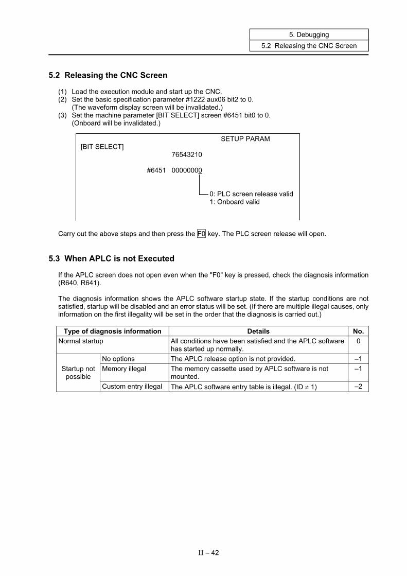
5. Debugging 5.2 Releasing the CNC Screen
5.2 Releasing the CNC Screen (1) Load the execution module and start up the CNC. (2) Set the basic specification parameter #1222 aux06 bit2 to 0. (The waveform display screen will be invalidated.) (3) Set the machine parameter [BIT SELECT] screen #6451 bit0 to 0. (Onboard will be invalidated.) SETUP PARAM [BIT SELECT] 76543210 #6451 00000000 0: PLC screen release valid 1: Onboard valid Carry out the above steps and then press the F0 key. The PLC screen release will open.
5.3 When APLC is not Executed If the APLC screen does not open even when the "F0" key is pressed, check the diagnosis information (R640, R641). The diagnosis information shows the APLC software startup state. If the startup conditions are not satisfied, startup will be disabled and an error status will be set. (If there are multiple illegal causes, only information on the first illegality will be set in the order that the diagnosis is carried out.)
Type of diagnosis information Details No. Normal startup All conditions have been satisfied and the APLC software
has started up normally. 0
No options The APLC release option is not provided. –1 Memory illegal The memory cassette used by APLC software is not
mounted. –1 Startup not
possible Custom entry illegal The APLC software entry table is illegal. (ID ≠ 1) –2
II – 42
5. Debugging 5.4 Measures during System Failure (System Down)
5.4 Measures during System Failure (System Down) If the system fails when the F0 key is pressed or when a menu key is pressed while the F0 screen is displayed, the display data or screen function program must be reviewed.
Examples of cause and measures • An end code (0 to –1) was not added to the display data. • Display data was assigned on the automatic variable. → Always assign the display data on the ROM data or global variables. • The enquet display data pointer was not correct. • The display data was illegal.
II – 43

6. Precautions for Programming 6.1 Storage Class and Storage Area
6. Precautions for Programming
6.1 Storage Class and Storage Area There are four storage classes. • Automatic variable (auto) • Static variable (static) • Global variable (extern) • Register variable (register) Refer to books of C language for details on the storage class. The storage area is divided as shown below. Stack in RAM memory ...... Automatic variable
Area in RAM memory........ Static variable or global variable that is not initialized Area in ROM memory ....... Static variable or global variable that is initialized Register in CPU ................ Register variable
Storage area
II – 44
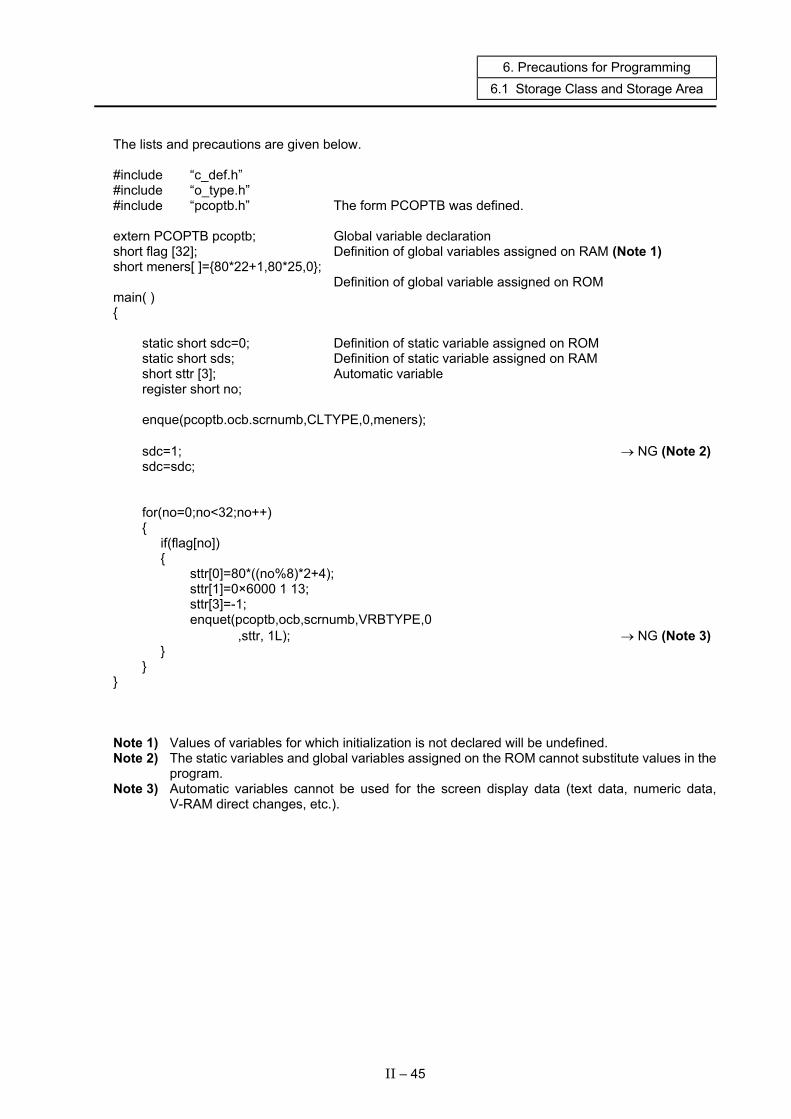
6. Precautions for Programming 6.1 Storage Class and Storage Area
The lists and precautions are given below. #include “c_def.h” #include “o_type.h” #include “pcoptb.h” The form PCOPTB was defined. extern PCOPTB pcoptb; Global variable declaration short flag [32]; Definition of global variables assigned on RAM (Note 1) short meners[ ]={80*22+1,80*25,0}; Definition of global variable assigned on ROM main( ) { static short sdc=0; Definition of static variable assigned on ROM static short sds; Definition of static variable assigned on RAM short sttr [3]; Automatic variable register short no; enque(pcoptb.ocb.scrnumb,CLTYPE,0,meners); sdc=1; → NG (Note 2) sdc=sdc; for(no=0;no<32;no++) { if(flag[no]) { sttr[0]=80*((no%8)*2+4); sttr[1]=0×6000 1 13; sttr[3]=-1; enquet(pcoptb,ocb,scrnumb,VRBTYPE,0 ,sttr, 1L); → NG (Note 3) } } } Note 1) Values of variables for which initialization is not declared will be undefined. Note 2) The static variables and global variables assigned on the ROM cannot substitute values in the
program. Note 3) Automatic variables cannot be used for the screen display data (text data, numeric data,
V-RAM direct changes, etc.).
II – 45
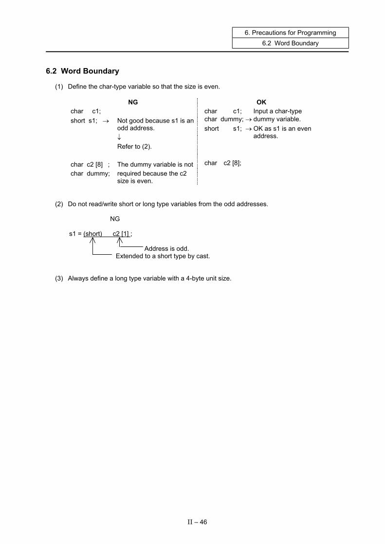
6. Precautions for Programming 6.2 Word Boundary
6.2 Word Boundary (1) Define the char-type variable so that the size is even.
NG OK char c1; short s1; → Not good because s1 is an odd address. ↓ Refer to (2). char c2 [8] ; The dummy variable is not char dummy; required because the c2 size is even.
char c1; Input a char-type char dummy; → dummy variable. short s1; → OK as s1 is an even address. char c2 [8];
(2) Do not read/write short or long type variables from the odd addresses.
NG
s1 = (short) c2 [1] ; Address is odd. Extended to a short type by cast. (3) Always define a long type variable with a 4-byte unit size.
II – 46

III. Sample Programs

1. Development Procedure
1. Development Procedure The points of the APLC program development are explained in this section using a sample program as an example. The procedure is as follows. (The numbers on the left indicate the chapter numbers.) 2. Determining of screen specifications and screen transition ↓ 2.1 Determining the screen specifications ↓ 2.2 Determining the screen transition ↓ 2.3 Defining the global data ↓ 3. Creation of the setting area data ↓ 4. Creation of M_OPE selective function address table and M_OPE selective functions ↓ 4.1 Creation of M_OPE selective function address table ↓ 4.2 Creation of M_OPE selective functions ↓ 5. Creation of screen decision table and M_OPE screen functions ↓ 5.1 Creation of screen decision table ↓ 5.2 Creation of M_OPE screen functions ↓ 6. Creation of M_OPE power-on-time initialize function and M_OPE F0 key initialize function ↓ 7. Creation of M_OPE key input pre-process functions and M_OPE key input post-process functions ↓ 8. Creation of M_OPE always called functions
III – 1
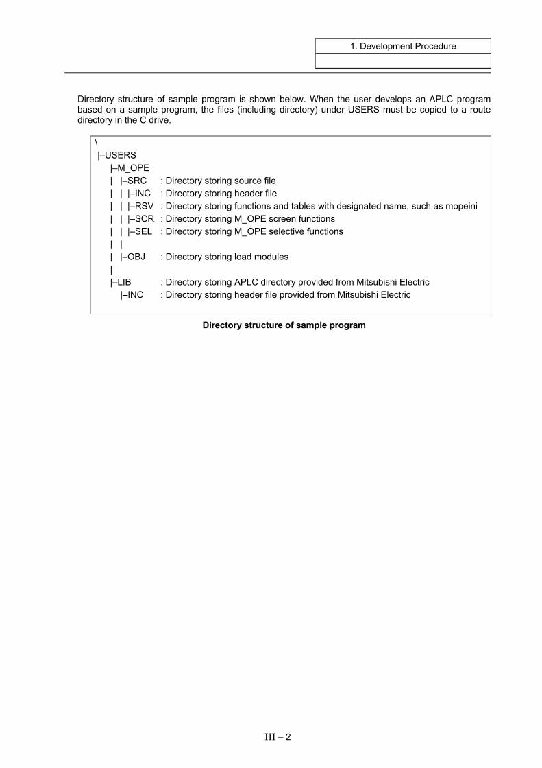
1. Development Procedure
Directory structure of sample program is shown below. When the user develops an APLC program based on a sample program, the files (including directory) under USERS must be copied to a route directory in the C drive.
\ |–USERS |–M_OPE | |–SRC : Directory storing source file | | |–INC : Directory storing header file | | |–RSV : Directory storing functions and tables with designated name, such as mopeini | | |–SCR : Directory storing M_OPE screen functions | | |–SEL : Directory storing M_OPE selective functions | | | |–OBJ : Directory storing load modules | |–LIB : Directory storing APLC directory provided from Mitsubishi Electric |–INC : Directory storing header file provided from Mitsubishi Electric
Directory structure of sample program
III – 2
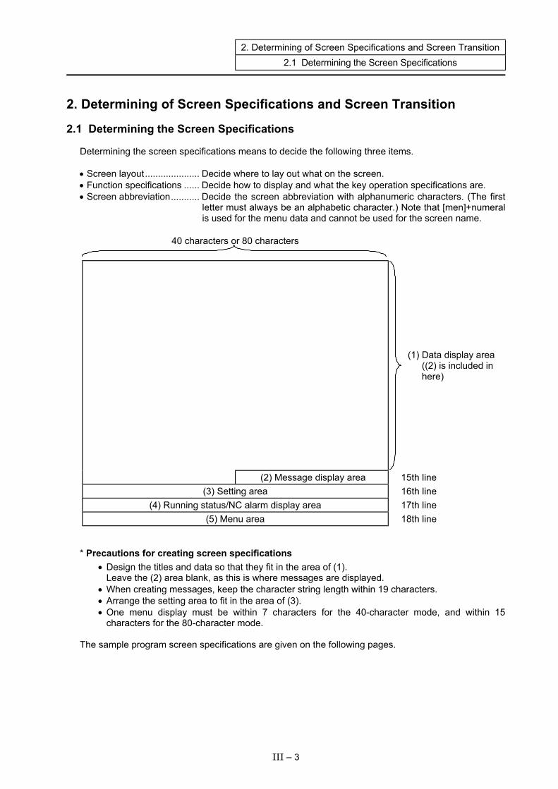
2. Determining of Screen Specifications and Screen Transition 2.1 Determining the Screen Specifications
III – 3
2. Determining of Screen Specifications and Screen Transition
2.1 Determining the Screen Specifications Determining the screen specifications means to decide the following three items. • Screen layout..................... Decide where to lay out what on the screen. • Function specifications ...... Decide how to display and what the key operation specifications are. • Screen abbreviation........... Decide the screen abbreviation with alphanumeric characters. (The first
letter must always be an alphabetic character.) Note that [men]+numeral is used for the menu data and cannot be used for the screen name.
40 characters or 80 characters
(1) Data display area ((2) is included in here)
(2) Message display area 15th line (3) Setting area 16th line
(4) Running status/NC alarm display area 17th line (5) Menu area 18th line
* Precautions for creating screen specifications
• Design the titles and data so that they fit in the area of (1). Leave the (2) area blank, as this is where messages are displayed. • When creating messages, keep the character string length within 19 characters. • Arrange the setting area to fit in the area of (3). • One menu display must be within 7 characters for the 40-character mode, and within 15
characters for the 80-character mode. The sample program screen specifications are given on the following pages.

2. Determining of Screen Specifications and Screen Transition 2.1 Determining the Screen Specifications
III – 4
1) Screen layout
MAIN SCREEN 12345678901234567 1 Program No. 2 X [mm] 3 Y [mm] 4 Z [mm] 5 Data amount 6 Z-axis tool [mm] 7 Work Coor. [mm] 8 Error Value [mm] [LOAD MONITOR ] [LOAD DATA SET ] [ ] [ ] [ ]
Screen 1 MAIN SCREEN LOAD MONITORING
LOAD DATA X Z S VALUE % 0 0 0 [ ] [ L-SET ] [ ] [ ] [ EXIT ]
Screen 2 LOAD MONITORING SCREEN
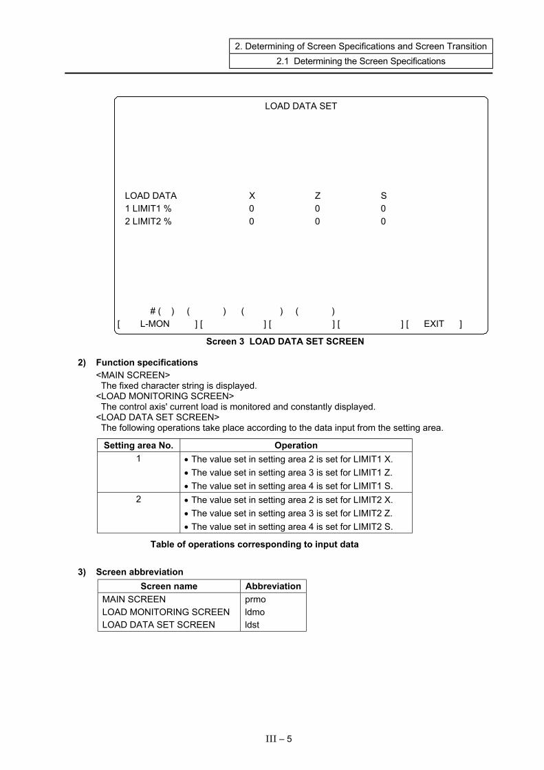
2. Determining of Screen Specifications and Screen Transition 2.1 Determining the Screen Specifications
Screen 3 LOAD DATA SET SCREEN
LOAD DATA SET LOAD DATA X Z S 1 LIMIT1 % 0 0 0 2 LIMIT2 % 0 0 0 # ( ) ( ) ( ) ( ) [ L-MON ] [ ] [ ] [ ] [ EXIT ]
2) Function specifications
<MAIN SCREEN> The fixed character string is displayed. <LOAD MONITORING SCREEN> The control axis' current load is monitored and constantly displayed. <LOAD DATA SET SCREEN> The following operations take place according to the data input from the setting area.
Setting area No. Operation 1 • The value set in setting area 2 is set for LIMIT1 X.
• The value set in setting area 3 is set for LIMIT1 Z. • The value set in setting area 4 is set for LIMIT1 S.
2 • The value set in setting area 2 is set for LIMIT2 X. • The value set in setting area 3 is set for LIMIT2 Z. • The value set in setting area 4 is set for LIMIT2 S.
Table of operations corresponding to input data
3) Screen abbreviation
Screen name Abbreviation MAIN SCREEN LOAD MONITORING SCREEN LOAD DATA SET SCREEN
prmo ldmo ldst
III – 5
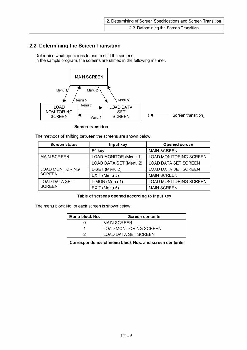
2. Determining of Screen Specifications and Screen Transition 2.2 Determining the Screen Transition
2.2 Determining the Screen Transition Determine what operations to use to shift the screens. In the sample program, the screens are shifted in the following manner.
MAIN SCREEN
LOAD NOMITORING
SCREEN
LOAD DATA SET
SCREEN ( Screen transition)
Menu 1
Menu 5 Menu 5
Menu 2
Menu 2
Menu 1
Screen transition The methods of shifting between the screens are shown below.
Screen status Input key Opened screen – F0 key MAIN SCREEN
LOAD MONITOR (Menu 1) LOAD MONITORING SCREEN MAIN SCREEN LOAD DATA SET (Menu 2) LOAD DATA SET SCREEN L-SET (Menu 2) LOAD DATA SET SCREEN LOAD MONITORING
SCREEN EXIT (Menu 5) MAIN SCREEN L-MON (Menu 1) LOAD MONITORING SCREEN LOAD DATA SET
SCREEN EXIT (Menu 5) MAIN SCREEN
Table of screens opened according to input key The menu block No. of each screen is shown below.
Menu block No. Screen contents 0 1 2
MAIN SCREEN LOAD MONITORING SCREEN LOAD DATA SET SCREEN
Correspondence of menu block Nos. and screen contents
III – 6

2. Determining of Screen Specifications and Screen Transition 2.3 Defining the Global Data
2.3 Defining the Global Data The global data to be added as M_OPE is defined. (1) Extracting the global data
The required global data is extracted based on the function to be realized with each M_OPE function. At that time, the related data is grouped as a structure and defined with the header file.
(2) Declaring the global data The extracted global data is declared with mglobal.c.
With each M_OPE function, the global data declared with mglobal.c is referred to externally and used. If the global data to be used is a structure, it is included with the header file. An example of the header file in the sample program and the contents of mglobal.c are shown below.
III – 7
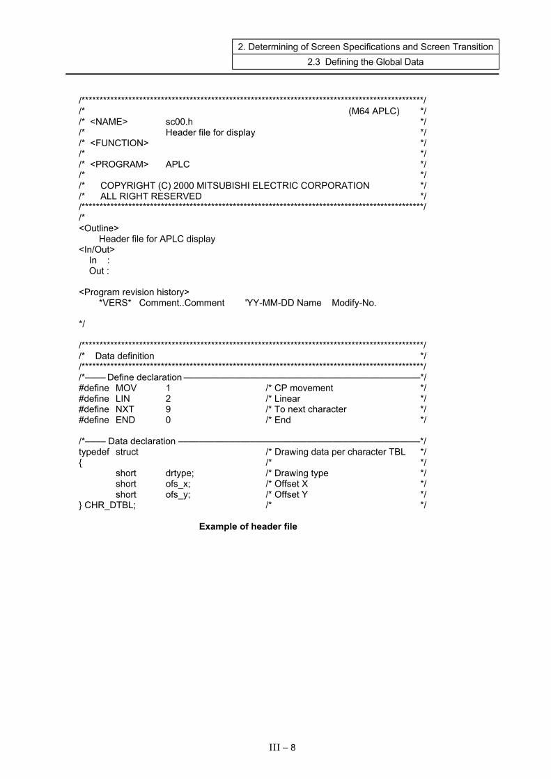
2. Determining of Screen Specifications and Screen Transition 2.3 Defining the Global Data
/***********************************************************************************************/ /* (M64 APLC) */ /* <NAME> sc00.h */ /* Header file for display */ /* <FUNCTION> */ /* */ /* <PROGRAM> APLC */ /* */ /* COPYRIGHT (C) 2000 MITSUBISHI ELECTRIC CORPORATION */ /* ALL RIGHT RESERVED */ /***********************************************************************************************/ /* <Outline> Header file for APLC display <In/Out> In : Out : <Program revision history> *VERS* Comment..Comment 'YY-MM-DD Name Modify-No. */ /***********************************************************************************************/ /* Data definition */ /***********************************************************************************************/ /*–––– Define declaration ––––––––––––––––––––––––––––––––––––––––––––––*/ #define MOV 1 /* CP movement */ #define LIN 2 /* Linear */ #define NXT 9 /* To next character */ #define END 0 /* End */ /*–––– Data declaration –––––––––––––––––––––––––––––––––––––––––––––––*/ typedef struct /* Drawing data per character TBL */ { /* */ short drtype; /* Drawing type */ short ofs_x; /* Offset X */ short ofs_y; /* Offset Y */ } CHR_DTBL; /* */ Example of header file
III – 8
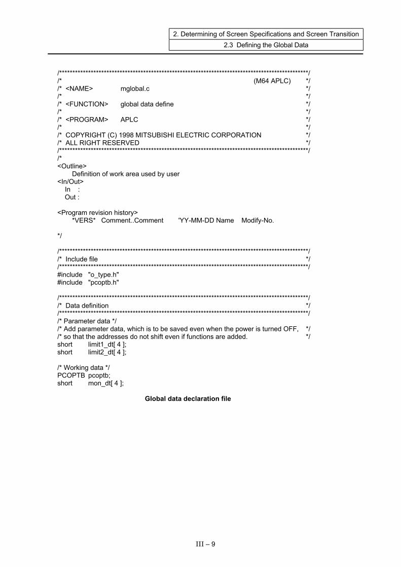
2. Determining of Screen Specifications and Screen Transition 2.3 Defining the Global Data
/***********************************************************************************************/ /* (M64 APLC) */ /* <NAME> mglobal.c */ /* */ /* <FUNCTION> global data define */ /* */ /* <PROGRAM> APLC */ /* */ /* COPYRIGHT (C) 1998 MITSUBISHI ELECTRIC CORPORATION */ /* ALL RIGHT RESERVED */ /***********************************************************************************************/ /* <Outline> Definition of work area used by user <In/Out> In : Out : <Program revision history> *VERS* Comment..Comment 'YY-MM-DD Name Modify-No. */ /***********************************************************************************************/ /* Include file */ /***********************************************************************************************/ #include "o_type.h" #include "pcoptb.h" /***********************************************************************************************/ /* Data definition */ /***********************************************************************************************/ /* Parameter data */ /* Add parameter data, which is to be saved even when the power is turned OFF, */ /* so that the addresses do not shift even if functions are added. */ short limit1_dt[ 4 ]; short limit2_dt[ 4 ]; /* Working data */ PCOPTB pcoptb; short mon_dt[ 4 ]; Global data declaration file
III – 9
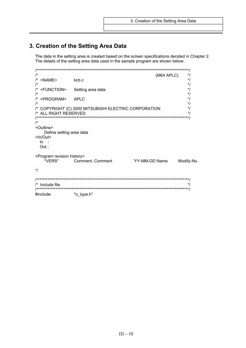
3. Creation of the Setting Area Data
3. Creation of the Setting Area Data The data in the setting area is created based on the screen specifications decided in Chapter 2. The details of the setting area data used in the sample program are shown below. /***********************************************************************************************/ /* (M64 APLC) */ /* <NAME> kcb.c */ /* */ /* <FUNCTION> Setting area data */ /* */ /* <PROGRAM> APLC */ /* */ /* COPYRIGHT (C) 2000 MITSUBISHI ELECTRIC CORPORATION */ /* ALL RIGHT RESERVED */ /***********************************************************************************************/ /* <Outline> Define setting area data <In/Out> In : Out : <Program revision history> *VERS* Comment..Comment 'YY-MM-DD Name Modify-No. */ /***********************************************************************************************/ /* Include file */ /***********************************************************************************************/ #include "o_type.h"
III – 10
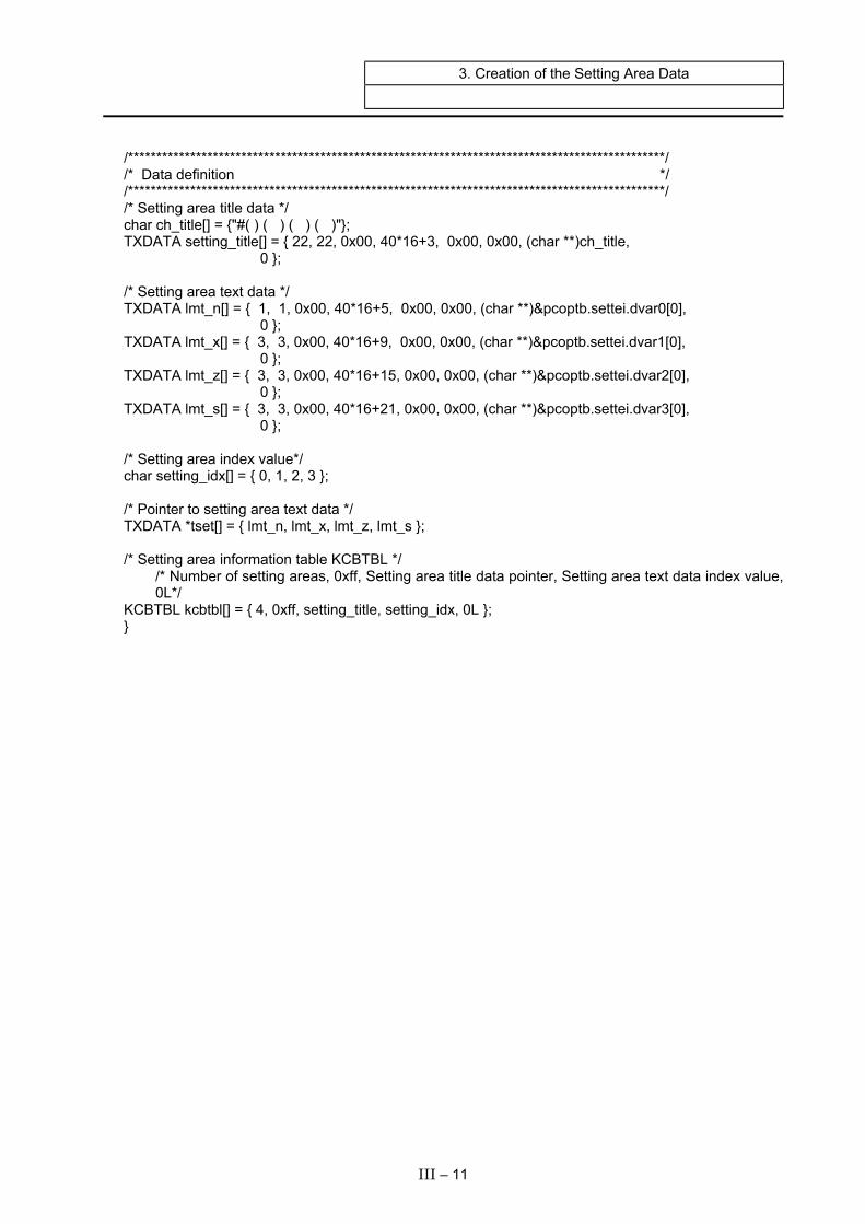
3. Creation of the Setting Area Data
/***********************************************************************************************/ /* Data definition */ /***********************************************************************************************/ /* Setting area title data */ char ch_title[] = {"#( ) ( ) ( ) ( )"}; TXDATA setting_title[] = { 22, 22, 0x00, 40*16+3, 0x00, 0x00, (char **)ch_title, 0 }; /* Setting area text data */ TXDATA lmt_n[] = { 1, 1, 0x00, 40*16+5, 0x00, 0x00, (char **)&pcoptb.settei.dvar0[0], 0 }; TXDATA lmt_x[] = { 3, 3, 0x00, 40*16+9, 0x00, 0x00, (char **)&pcoptb.settei.dvar1[0], 0 }; TXDATA lmt_z[] = { 3, 3, 0x00, 40*16+15, 0x00, 0x00, (char **)&pcoptb.settei.dvar2[0], 0 }; TXDATA lmt_s[] = { 3, 3, 0x00, 40*16+21, 0x00, 0x00, (char **)&pcoptb.settei.dvar3[0], 0 }; /* Setting area index value*/ char setting_idx[] = { 0, 1, 2, 3 }; /* Pointer to setting area text data */ TXDATA *tset[] = { lmt_n, lmt_x, lmt_z, lmt_s }; /* Setting area information table KCBTBL */ /* Number of setting areas, 0xff, Setting area title data pointer, Setting area text data index value,
0L*/ KCBTBL kcbtbl[] = { 4, 0xff, setting_title, setting_idx, 0L }; }
III – 11

4. Creation of M_OPE Selective Function Address Table and M_OPE Selective Functions 4.1 Creation of M_OPE Selective Function Address Table
4. Creation of M_OPE Selective Function Address Table and M_OPE Selective Functions
4.1 Creation of M_OPE Selective Function Address Table
Processes that might be shared on each screen are set as M_OPE selective functions. In the sample program, the following process is handled as an M_OPE selective function.
• Reset display request (Function name: mquerst () ) • 40-character mode selection (Function name: mode40 () ) • 80-character mode selection (Function name: mode80 () ) • Clearing of screen display area (Function name: mscrcl () ) • Display of menu (Function name: mendsp () ) • Highlighting of menu (Function name: menuhi () ) • Setting area process (Function name: skey () )
Next, determine the order that the M_OPE selective functions are to be called, and assign them to the selective call flag bits. These are assigned as shown below in the sample program.
Bit No. 15 14 13 12 11 10 9 8 7 6 5 4 3 2 1 0*
Selective call flag
Execution order
Setting area process Highlighting of menu Display of menu Clearing of screen display area 80-character mode 40-character mode Reset display request
* Bit No. 0 should be left empty as the M_OPE selective function that should be executed first may be added.
Assignment of M_OPE selective functions to selective call flag The following pages show the state when the M_OPE selective function address table (mseltb.c) is created based on the above assignments. This M_OPE selective function address table is created under SRC\RSV.
III – 12

4. Creation of M_OPE Selective Function Address Table and M_OPE Selective Functions 4.1 Creation of M_OPE Selective Function Address Table
/***********************************************************************************************/ /* (M64 system) */ /* <NAME> mseltb.c */ /* <FUNCTION> m_ope selective function table */ /* */ /* <PROGRAM> APLC */ /* */ /* COPYRIGHT (C) 1998 MITSUBISHI ELECTRIC CORPORATION */ /* ALL RIGHT RESERVED */ /***********************************************************************************************/ /* <Outline> The function table corresponds to the following bits Bit1: Reset display request Bit2: 40-character mode selection Bit3: 80-character mode selection Bit4: Clearing of screen display area Bit5: Display of menu Bit6: Highlighting of menu Bit7: Setting area process <In/Out> In : – Out : – <Program revision history> *VERS* Comment..Comment 'YY-MM-DD Name Modify-No. */ /***********************************************************************************************/ /* External reference */ /***********************************************************************************************/ extern void mquerst() ; extern void mode40() ; extern void mode80() ; extern void mscrcl() ; extern void mendsp() ; extern void menuhi() ; extern void skey() ;
III – 13
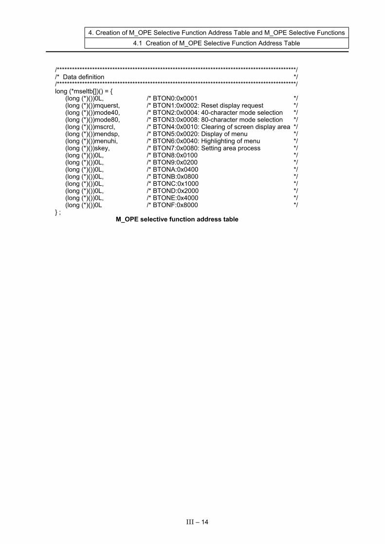
4. Creation of M_OPE Selective Function Address Table and M_OPE Selective Functions 4.1 Creation of M_OPE Selective Function Address Table
/***********************************************************************************************/ /* Data definition */ /***********************************************************************************************/ long (*mseltb[])() = { (long (*)())0L, /* BTON0:0x0001 */ (long (*)())mquerst, /* BTON1:0x0002: Reset display request */ (long (*)())mode40, /* BTON2:0x0004: 40-character mode selection */ (long (*)())mode80, /* BTON3:0x0008: 80-character mode selection */ (long (*)())mscrcl, /* BTON4:0x0010: Clearing of screen display area */ (long (*)())mendsp, /* BTON5:0x0020: Display of menu */ (long (*)())menuhi, /* BTON6:0x0040: Highlighting of menu */ (long (*)())skey, /* BTON7:0x0080: Setting area process */ (long (*)())0L, /* BTON8:0x0100 */ (long (*)())0L, /* BTON9:0x0200 */ (long (*)())0L, /* BTONA:0x0400 */ (long (*)())0L, /* BTONB:0x0800 */ (long (*)())0L, /* BTONC:0x1000 */ (long (*)())0L, /* BTOND:0x2000 */ (long (*)())0L, /* BTONE:0x4000 */ (long (*)())0L /* BTONF:0x8000 */ } ; M_OPE selective function address table
III – 14
4. Creation of M_OPE Selective Function Address Table and M_OPE Selective Functions 4.2 Creation of M_OPE Selective Functions
4.2 Creation of M_OPE Selective Functions The M_OPE selective functions are created under directory SRC\SEL. The setting area process (skey()) is a support function and does not need to be created. The details of the M_OPE selective functions used in the sample program are given on the following pages. <M_OPE selective function created in sample program> • M_OPE selective function for resetting display request • M_OPE selective function for changing 40-character mode • M_OPE selective function for changing 80-character mode • M_OPE selective function for clearing screen display area • M_OPE selective function for displaying menu • M_OPE selective function for highlighting menu The M_OPE selective functions created at this time only need to be called once when the screen changes. Thus, the selective call flag in the OCB table at the end of the function must be turned OFF. (Refer to section "3.5.1 OCB Table" for details.)
III – 15
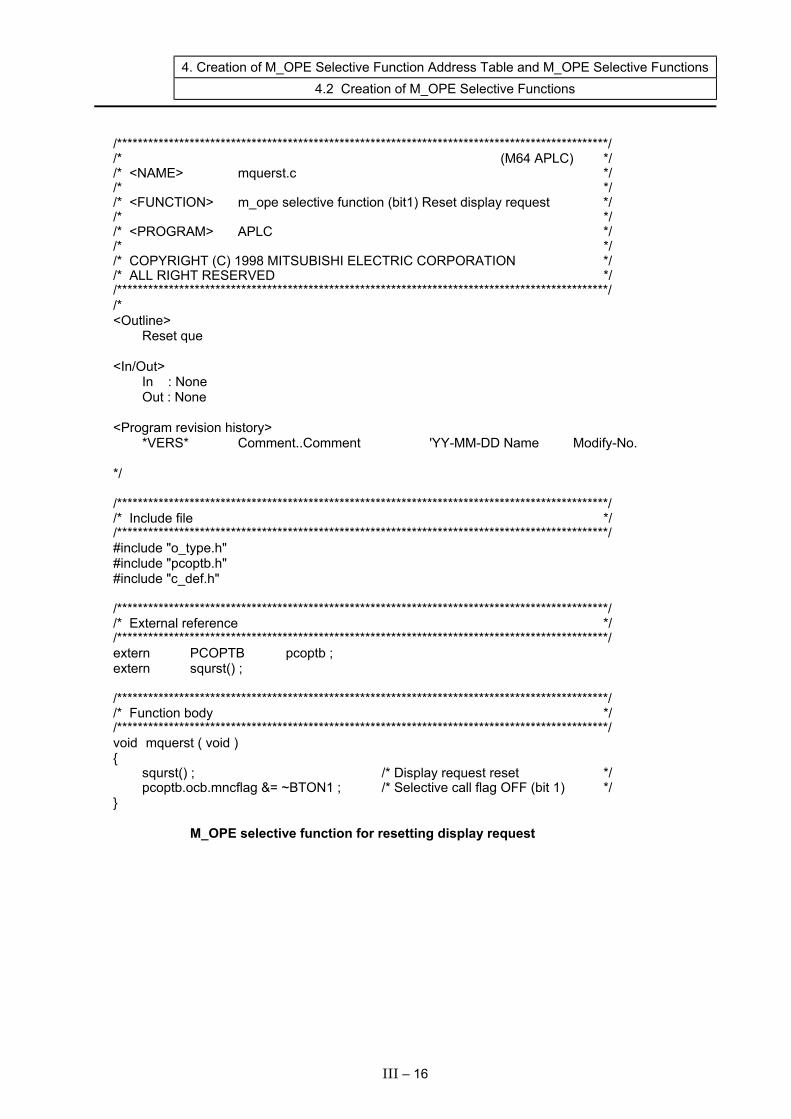
4. Creation of M_OPE Selective Function Address Table and M_OPE Selective Functions 4.2 Creation of M_OPE Selective Functions
/***********************************************************************************************/ /* (M64 APLC) */ /* <NAME> mquerst.c */ /* */ /* <FUNCTION> m_ope selective function (bit1) Reset display request */ /* */ /* <PROGRAM> APLC */ /* */ /* COPYRIGHT (C) 1998 MITSUBISHI ELECTRIC CORPORATION */ /* ALL RIGHT RESERVED */ /***********************************************************************************************/ /* <Outline> Reset que <In/Out> In : None Out : None <Program revision history> *VERS* Comment..Comment 'YY-MM-DD Name Modify-No. */ /***********************************************************************************************/ /* Include file */ /***********************************************************************************************/ #include "o_type.h" #include "pcoptb.h" #include "c_def.h" /***********************************************************************************************/ /* External reference */ /***********************************************************************************************/ extern PCOPTB pcoptb ; extern squrst() ; /***********************************************************************************************/ /* Function body */ /***********************************************************************************************/ void mquerst ( void ) { squrst() ; /* Display request reset */ pcoptb.ocb.mncflag &= ~BTON1 ; /* Selective call flag OFF (bit 1) */ } M_OPE selective function for resetting display request
III – 16
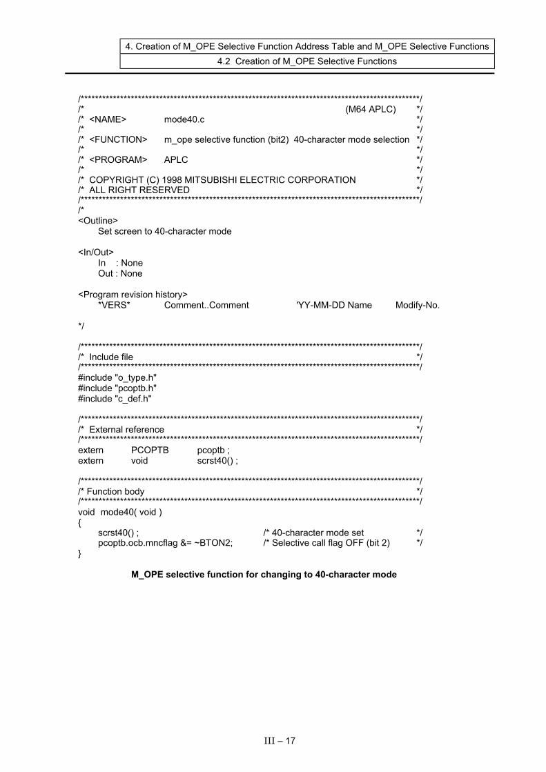
4. Creation of M_OPE Selective Function Address Table and M_OPE Selective Functions 4.2 Creation of M_OPE Selective Functions
/***********************************************************************************************/ /* (M64 APLC) */ /* <NAME> mode40.c */ /* */ /* <FUNCTION> m_ope selective function (bit2) 40-character mode selection */ /* */ /* <PROGRAM> APLC */ /* */ /* COPYRIGHT (C) 1998 MITSUBISHI ELECTRIC CORPORATION */ /* ALL RIGHT RESERVED */ /***********************************************************************************************/ /* <Outline> Set screen to 40-character mode <In/Out> In : None Out : None <Program revision history> *VERS* Comment..Comment 'YY-MM-DD Name Modify-No. */ /***********************************************************************************************/ /* Include file */ /***********************************************************************************************/ #include "o_type.h" #include "pcoptb.h" #include "c_def.h" /***********************************************************************************************/ /* External reference */ /***********************************************************************************************/ extern PCOPTB pcoptb ; extern void scrst40() ; /***********************************************************************************************/ /* Function body */ /***********************************************************************************************/ void mode40( void ) { scrst40() ; /* 40-character mode set */ pcoptb.ocb.mncflag &= ~BTON2; /* Selective call flag OFF (bit 2) */ } M_OPE selective function for changing to 40-character mode
III – 17
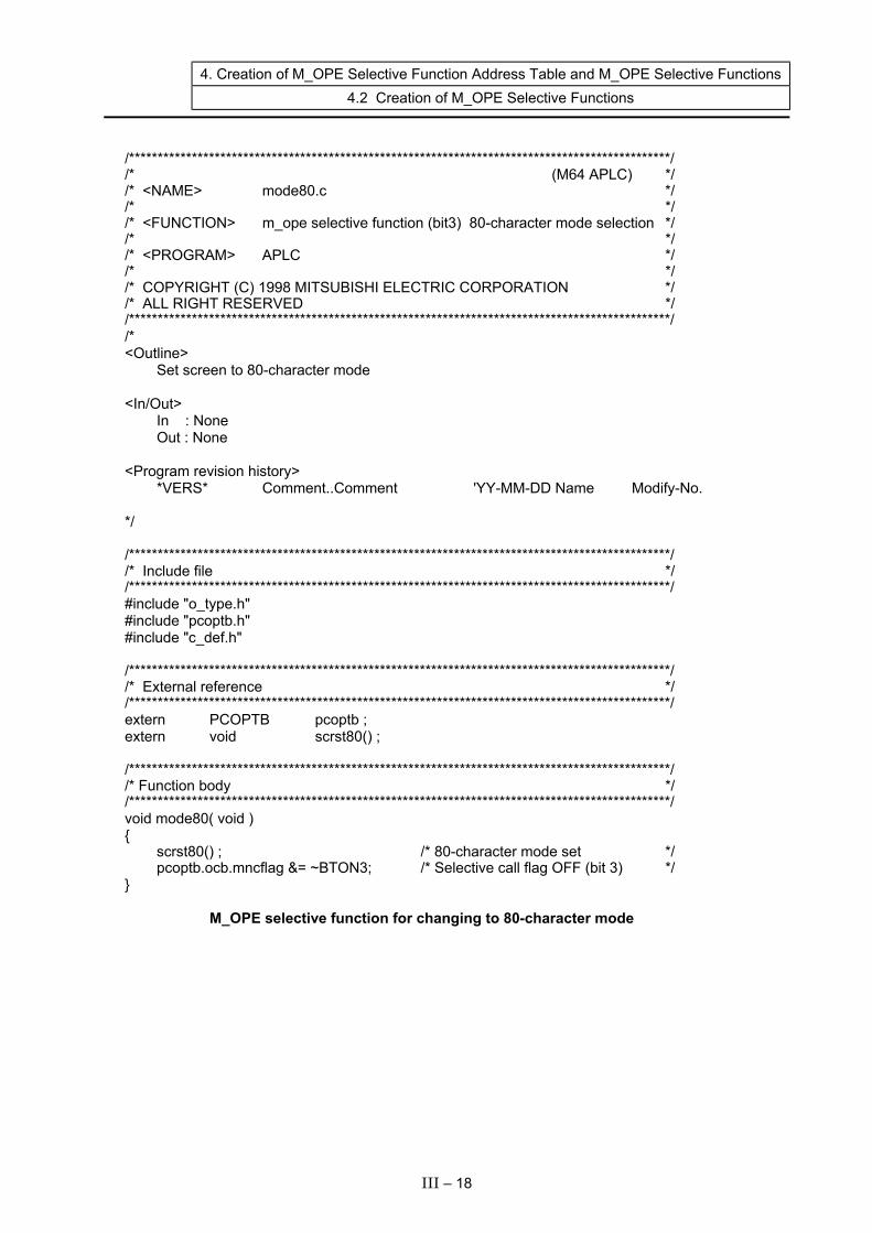
4. Creation of M_OPE Selective Function Address Table and M_OPE Selective Functions 4.2 Creation of M_OPE Selective Functions
/***********************************************************************************************/ /* (M64 APLC) */ /* <NAME> mode80.c */ /* */ /* <FUNCTION> m_ope selective function (bit3) 80-character mode selection */ /* */ /* <PROGRAM> APLC */ /* */ /* COPYRIGHT (C) 1998 MITSUBISHI ELECTRIC CORPORATION */ /* ALL RIGHT RESERVED */ /***********************************************************************************************/ /* <Outline> Set screen to 80-character mode <In/Out> In : None Out : None <Program revision history> *VERS* Comment..Comment 'YY-MM-DD Name Modify-No. */ /***********************************************************************************************/ /* Include file */ /***********************************************************************************************/ #include "o_type.h" #include "pcoptb.h" #include "c_def.h" /***********************************************************************************************/ /* External reference */ /***********************************************************************************************/ extern PCOPTB pcoptb ; extern void scrst80() ; /***********************************************************************************************/ /* Function body */ /***********************************************************************************************/ void mode80( void ) { scrst80() ; /* 80-character mode set */ pcoptb.ocb.mncflag &= ~BTON3; /* Selective call flag OFF (bit 3) */ } M_OPE selective function for changing to 80-character mode
III – 18

4. Creation of M_OPE Selective Function Address Table and M_OPE Selective Functions 4.2 Creation of M_OPE Selective Functions
/***********************************************************************************************/ /* (M64 APLC) */ /* <NAME> mscrcl.c */ /* */ /* <FUNCTION> m_ope selective function (bit4) Clearing of screen display area */ /* */ /* <PROGRAM> APLC */ /* */ /* COPYRIGHT (C) 1998 MITSUBISHI ELECTRIC CORPORATION */ /* ALL RIGHT RESERVED */ /***********************************************************************************************/ /* <Outline> Clear lines 1 to 18 on character screen Clear graphic screen Clear cursors 1 and 2 <In/Out> In : None Out : None <Program revision history> *VERS* Comment..Comment 'YY-MM-DD Name Modify-No. */ /***********************************************************************************************/ /* Include file */ /***********************************************************************************************/ #include "o_type.h" #include "c_def.h" #include "pcoptb.h" /***********************************************************************************************/ /* External reference */ /***********************************************************************************************/ extern PCOPTB pcoptb ; extern texers() ; extern graclr() ; extern cursor() ;
III – 19

4. Creation of M_OPE Selective Function Address Table and M_OPE Selective Functions 4.2 Creation of M_OPE Selective Functions
/***********************************************************************************************/ /* Function body */ /***********************************************************************************************/ void mscrcl( void ) { /* Character screen line 1 to 18 data erase */ static short txclr4[] = {1, 40*18, 0} ; /* 1-line 40-digit screen */ static short txclr8[] = {1, 80*18, 0} ; /* 1-line 80-digit screen */ short *texclr ; /* Text erase data row */ if(pcoptb.ocb.modflg == 1) { /* 80-digit display */ texclr = txclr8 ; /* 80-digit screen data selection */ } else { /* 40-digit display */ texclr = txclr4 ; /* 40-digit screen data selection */ } texers(texclr) ; /* Text erase */ graclr(0x000f, 0, 0, 640, 409) ; /* Graphics erase */ cursor(pcoptb.ocb.scrnumb, 0xFE, 0, 0x8000, 0) ; /* Cursor 1 erase */ pcoptb.ocb.mncflag &= ~BTON4 ; /* bit4 OFF */ } M_OPE selective function for erasing screen
III – 20
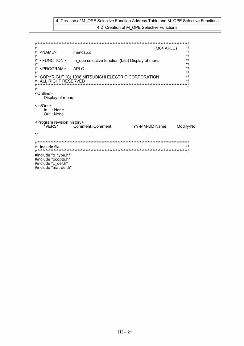
4. Creation of M_OPE Selective Function Address Table and M_OPE Selective Functions 4.2 Creation of M_OPE Selective Functions
/***********************************************************************************************/ /* (M64 APLC) */ /* <NAME> mendsp.c */ /* */ /* <FUNCTION> m_ope selective function (bit5) Display of menu */ /* */ /* <PROGRAM> APLC */ /* */ /* COPYRIGHT (C) 1998 MITSUBISHI ELECTRIC CORPORATION */ /* ALL RIGHT RESERVED */ /***********************************************************************************************/ /* <Outline> Display of menu <In/Out> In : None Out : None <Program revision history> *VERS* Comment..Comment 'YY-MM-DD Name Modify-No. */ /***********************************************************************************************/ /* Include file */ /***********************************************************************************************/ #include "o_type.h" #include "pcoptb.h" #include "c_def.h" #include "matrdef.h"
III – 21

4. Creation of M_OPE Selective Function Address Table and M_OPE Selective Functions 4.2 Creation of M_OPE Selective Functions
/***********************************************************************************************/ /* External reference */ /***********************************************************************************************/ char dmen0[] = {"[LOAD MONITOR ][LOAD DATA SET ][ ][ ][ ]"}; char dmen1[] = {"[ ] [T-SET] [ ] [ ] [EXIT ]"}; char dmen2[] = {"[T-MON] [ ] [ ] [ ] [EXIT ]"}; TXDATA men0[] = {80,80,C_WK|NORMATR,80*17+1,0x00,0x00,(char **)dmen0,0}; TXDATA men1[] = {39,39,C_WK|NORMATR,40*17+1,0x00,0x00,(char **)dmen1,0}; TXDATA men2[] = {39,39,C_WK|NORMATR,40*17+1,0x00,0x00,(char **)dmen2,0}; /***********************************************************************************************/ /* Function body */ /***********************************************************************************************/ void mendsp( void ) { static short meners40[] = {40*17+1, 40*18, 0}; /* Menu area erase data 40-character */ static short meners80[] = {80*17+1, 80*18, 0}; /* Menu area erase data 80-character */ static TXDATA *menutx[] = {men0, men1, men2}; /* Menu display address data */ short *meners; if(pcoptb.ocb.modflg == 1) { meners = meners80; } else { meners = meners40; } smenud( menutx, meners, pcoptb.ocb.mnblno ); pcoptb.ocb.mncflag &= ~BTON5 ; /* Selective call flag OFF (bit 5) */ } M_OPE selective function for displaying menu
III – 22

4. Creation of M_OPE Selective Function Address Table and M_OPE Selective Functions 4.2 Creation of M_OPE Selective Functions
/***********************************************************************************************/ /* (M64 APLC) */ /* <NAME> menuhi.c */ /* */ /* <FUNCTION> m_ope selective function (bit6) Highlighting of menu */ /* */ /* <PROGRAM> APLC */ /* */ /* COPYRIGHT (C) 1998 MITSUBISHI ELECTRIC CORPORATION */ /* ALL RIGHT RESERVED */ /***********************************************************************************************/ /* <Outline> Highlighting of menu <In/Out> In : None Out : None <Program revision history> *VERS* Comment..Comment 'YY-MM-DD Name Modify-No. */ /***********************************************************************************************/ /* Include file */ /***********************************************************************************************/ #include "o_type.h" #include "pcoptb.h" #include "matrdef.h" /***********************************************************************************************/ /* External reference */ /***********************************************************************************************/ extern PCOPTB pcoptb;
III – 23

4. Creation of M_OPE Selective Function Address Table and M_OPE Selective Functions 4.2 Creation of M_OPE Selective Functions
/***********************************************************************************************/ /* Function body */ /***********************************************************************************************/ viod menuhi( void ) { /* Attribute data for menu highlighting */ static short menatr81[] = {80*17+ 1, 0x0400|16,-1}; static short menatr82[] = {80*17+17, 0x0400|16,-1}; static short menatr83[] = {80*17+33, 0x0400|16,-1}; static short menatr84[] = {80*17+48, 0x0400|16,-1}; static short menatr85[] = {80*17+64, 0x0400|16,-1}; static short menatr41[] = {40*17+ 1, 0x0400|8,-1}; static short menatr42[] = {40*17+ 9, 0x0400|8,-1}; static short menatr43[] = {40*17+17, 0x0400|8,-1}; static short menatr44[] = {40*17+25, 0x0400|8,-1}; static short menatr45[] = {40*17+33, 0x0400|8,-1}; static short *menatrp80[] = {menatr81, menatr82, menatr83, menatr84, menatr85}; static short *menatrp40[] = {menatr41, menatr42, menatr43, menatr44, menatr45}; short *menatrp; if(pcoptb.ocb.modflg == 1) { menatrp= menatrp80; } else { menatrp= menatrp40; } smenhi(menatrp,pcoptb.ocb.mnblno); /* Highlighting of menu */ pcoptb.ocb.mncflag &= ~BTON6 ; /* Selective call flag OFF (bit 5) */ } M_OPE selective function for highlighting menu
III – 24

5. Creation of Screen Decision Table and M_OPE Screen Functions 5.1 Creation of Screen Decision Table
5. Creation of Screen Decision Table and M_OPE Screen Functions
5.1 Creation of Screen Decision Table Next, the M_OPE screen functions for carrying out the screen display process of each release screen place on the CNC system is created. The created M_OPE screen functions are called out by registering them in the screen decision table. The M_OPE screen function names for each screen are determined as shown below. Set the M_OPE function names for each screen as shown below. The screen decision tables used to realize the screen transition decided with "2. Deciding the screen specifications/screen transition specifications" are shown on the following pages.
Screen name (Abbreviations are shown in parentheses)
Screen function name
MAIN SCREEN (prmo) LOAD MONITORING SCREEN (ldmo) LOAD DATA SET SCREEN (ldst)
mfprmo () mfldmo () mfldst ()
* The screen function name is abbreviated as [mf] + screen. The screen decision table is created under directory SRC\RSV.
III – 25

5. Creation of Screen Decision Table and M_OPE Screen Functions 5.1 Creation of Screen Decision Table
/***********************************************************************************************/ /* (M64 APLC) */ /* <NAME> menublk.c */ /* */ /* <FUNCTION> m_ope screen decision table */ /* */ /* <PROGRAM> APLC */ /* */ /* COPYRIGHT (C) 1998 MITSUBISHI ELECTRIC CORPORATION */ /* ALL RIGHT RESERVED */ /***********************************************************************************************/ /* <Outline> Tables for registering screen transition information <In/Out> In : – Out : – <Program revision history> *VERS* Comment..Comment 'YY-MM-DD Name Modify-No. */ /***********************************************************************************************/ /* Include file */ /***********************************************************************************************/ #include "o_type.h" #include "po_typ.h" /***********************************************************************************************/ /* External reference */ /***********************************************************************************************/ extern void mfprmo(void) ; /* MAIN SCREEN */ extern void mfldmo(void) ; /* LOAD MONITORING SCREEN */ extern void mfldst(void) ; /* LOAD DATA SET SCREEN */
III – 26
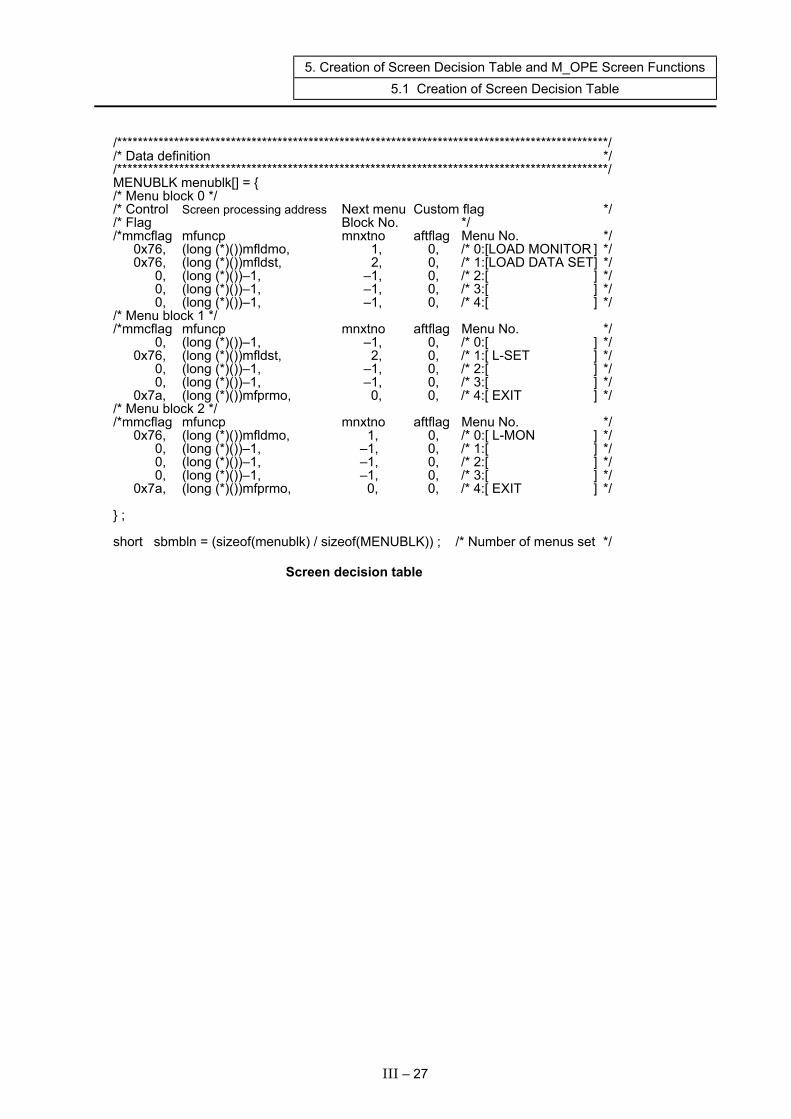
5. Creation of Screen Decision Table and M_OPE Screen Functions 5.1 Creation of Screen Decision Table
/***********************************************************************************************/ /* Data definition */ /***********************************************************************************************/ MENUBLK menublk[] = { /* Menu block 0 */ /* Control Screen processing address Next menu Custom flag */ /* Flag Block No. */ /*mmcflag mfuncp mnxtno aftflag Menu No. */ 0x76, (long (*)())mfldmo, 1, 0, /* 0:[LOAD MONITOR ] */ 0x76, (long (*)())mfldst, 2, 0, /* 1:[LOAD DATA SET ] */ 0, (long (*)())–1, –1, 0, /* 2:[ ] */ 0, (long (*)())–1, –1, 0, /* 3:[ ] */ 0, (long (*)())–1, –1, 0, /* 4:[ ] */ /* Menu block 1 */ /*mmcflag mfuncp mnxtno aftflag Menu No. */ 0, (long (*)())–1, –1, 0, /* 0:[ ] */ 0x76, (long (*)())mfldst, 2, 0, /* 1:[ L-SET ] */ 0, (long (*)())–1, –1, 0, /* 2:[ ] */ 0, (long (*)())–1, –1, 0, /* 3:[ ] */ 0x7a, (long (*)())mfprmo, 0, 0, /* 4:[ EXIT ] */ /* Menu block 2 */ /*mmcflag mfuncp mnxtno aftflag Menu No. */ 0x76, (long (*)())mfldmo, 1, 0, /* 0:[ L-MON ] */ 0, (long (*)())–1, –1, 0, /* 1:[ ] */ 0, (long (*)())–1, –1, 0, /* 2:[ ] */ 0, (long (*)())–1, –1, 0, /* 3:[ ] */ 0x7a, (long (*)())mfprmo, 0, 0, /* 4:[ EXIT ] */ } ; short sbmbln = (sizeof(menublk) / sizeof(MENUBLK)) ; /* Number of menus set */ Screen decision table
III – 27

5. Creation of Screen Decision Table and M_OPE Screen Functions 5.2 Creation of M_OPE Screen Functions
5.2 Creation of M_OPE Screen Functions The M_OPE screen functions are created in directory SRC\SCR as "function name.c". Each M_OPE screen function carries out the following type of process. • Screen display process • Setting area initialization (only on screens having a setting area) • Input key process (only on screens having a setting area) The basic flow of the M_OPE screen function process is shown below.
Screen process start
Screen selection timing?
Display screen
Setting area initialization
Input key input?
Screen constant process
Screen process end
Setting process
YES
NO
YES
NO Only on screens having a setting area
The details of the M_OPE screen functions in the sample program are shown on the following pages.
III – 28

5. Creation of Screen Decision Table and M_OPE Screen Functions 5.2 Creation of M_OPE Screen Functions
/***********************************************************************************************/ /* (M64 APLC) */ /* <NAME> mfprmo.c */ /* */ /* <FUNCTION> MAIN SCREEN */ /* */ /* <PROGRAM> APLC */ /* */ /* COPYRIGHT (C) 2000 MITSUBISHI ELECTRIC CORPORATION */ /* ALL RIGHT RESERVED */ /***********************************************************************************************/ /* <Outline> MAIN SCREEN process <In/Out> In : Out : <Program revision history *VERS* Comment..Comment 'YY-MM-DD Name Modify-No. */ /***********************************************************************************************/ /* Include file */ /***********************************************************************************************/ #include "g_def.h" #include "c_def.h" #include "i_def.h" #include "o_type.h" #include "pcoptb.h" /***********************************************************************************************/ /* External reference */ /***********************************************************************************************/ extern PCOPTB pcoptb;
III – 29
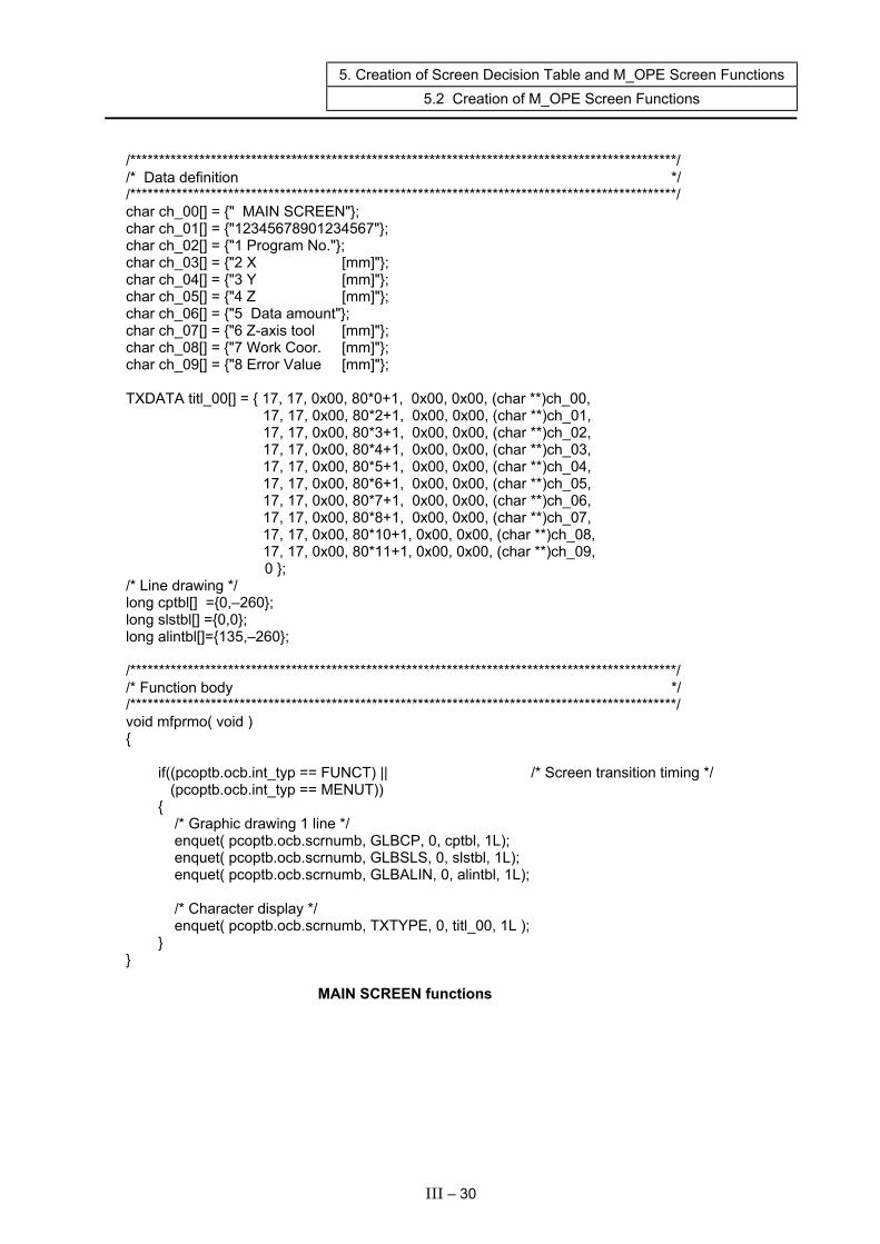
5. Creation of Screen Decision Table and M_OPE Screen Functions 5.2 Creation of M_OPE Screen Functions
/***********************************************************************************************/ /* Data definition */ /***********************************************************************************************/ char ch_00[] = {" MAIN SCREEN"}; char ch_01[] = {"12345678901234567"}; char ch_02[] = {"1 Program No."}; char ch_03[] = {"2 X [mm]"}; char ch_04[] = {"3 Y [mm]"}; char ch_05[] = {"4 Z [mm]"}; char ch_06[] = {"5 Data amount"}; char ch_07[] = {"6 Z-axis tool [mm]"}; char ch_08[] = {"7 Work Coor. [mm]"}; char ch_09[] = {"8 Error Value [mm]"}; TXDATA titl_00[] = { 17, 17, 0x00, 80*0+1, 0x00, 0x00, (char **)ch_00, 17, 17, 0x00, 80*2+1, 0x00, 0x00, (char **)ch_01, 17, 17, 0x00, 80*3+1, 0x00, 0x00, (char **)ch_02, 17, 17, 0x00, 80*4+1, 0x00, 0x00, (char **)ch_03, 17, 17, 0x00, 80*5+1, 0x00, 0x00, (char **)ch_04, 17, 17, 0x00, 80*6+1, 0x00, 0x00, (char **)ch_05, 17, 17, 0x00, 80*7+1, 0x00, 0x00, (char **)ch_06, 17, 17, 0x00, 80*8+1, 0x00, 0x00, (char **)ch_07, 17, 17, 0x00, 80*10+1, 0x00, 0x00, (char **)ch_08, 17, 17, 0x00, 80*11+1, 0x00, 0x00, (char **)ch_09, 0 }; /* Line drawing */ long cptbl[] ={0,–260}; long slstbl[] ={0,0}; long alintbl[]={135,–260}; /***********************************************************************************************/ /* Function body */ /***********************************************************************************************/ void mfprmo( void ) { if((pcoptb.ocb.int_typ == FUNCT) || /* Screen transition timing */ (pcoptb.ocb.int_typ == MENUT)) { /* Graphic drawing 1 line */ enquet( pcoptb.ocb.scrnumb, GLBCP, 0, cptbl, 1L); enquet( pcoptb.ocb.scrnumb, GLBSLS, 0, slstbl, 1L); enquet( pcoptb.ocb.scrnumb, GLBALIN, 0, alintbl, 1L); /* Character display */ enquet( pcoptb.ocb.scrnumb, TXTYPE, 0, titl_00, 1L ); } } MAIN SCREEN functions
III – 30
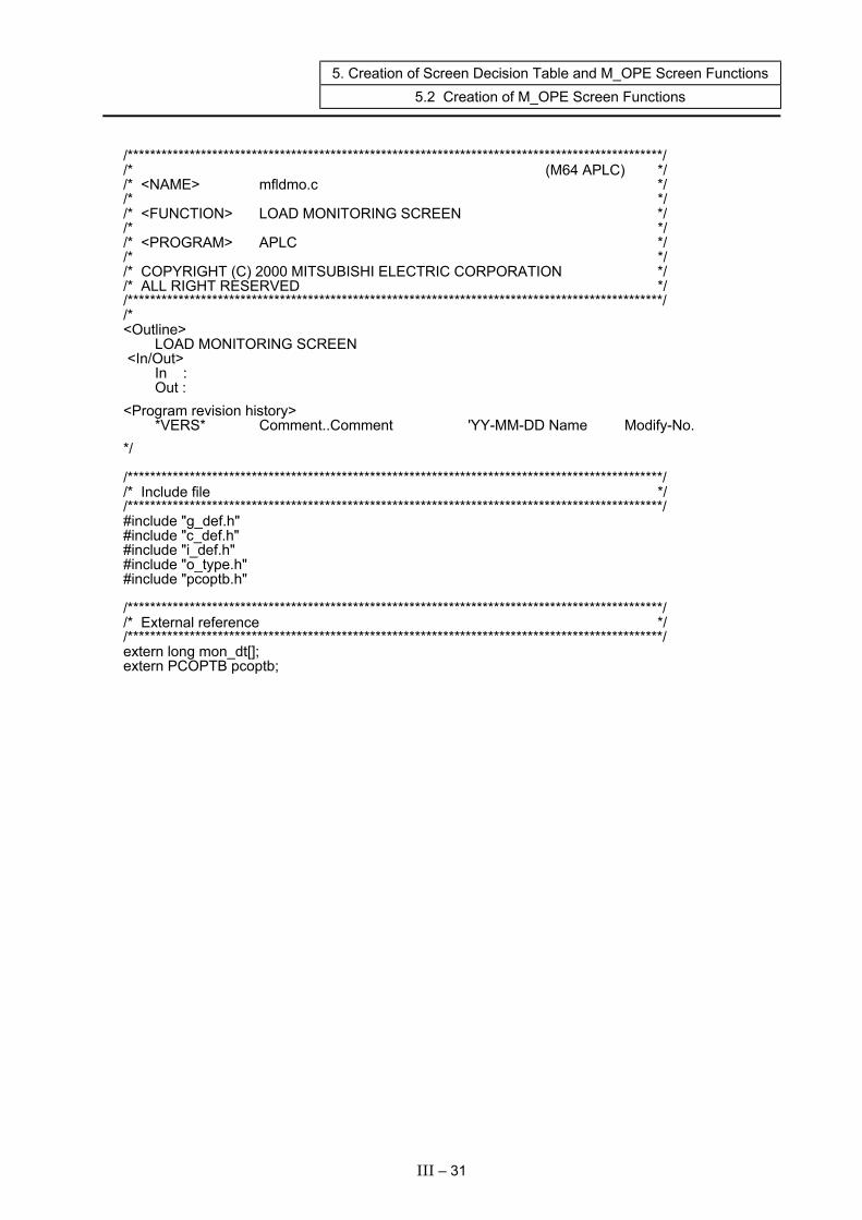
5. Creation of Screen Decision Table and M_OPE Screen Functions 5.2 Creation of M_OPE Screen Functions
/***********************************************************************************************/ /* (M64 APLC) */ /* <NAME> mfldmo.c */ /* */ /* <FUNCTION> LOAD MONITORING SCREEN */ /* */ /* <PROGRAM> APLC */ /* */ /* COPYRIGHT (C) 2000 MITSUBISHI ELECTRIC CORPORATION */ /* ALL RIGHT RESERVED */ /***********************************************************************************************/ /* <Outline> LOAD MONITORING SCREEN <In/Out> In : Out : <Program revision history> *VERS* Comment..Comment 'YY-MM-DD Name Modify-No. */ /***********************************************************************************************/ /* Include file */ /***********************************************************************************************/ #include "g_def.h" #include "c_def.h" #include "i_def.h" #include "o_type.h" #include "pcoptb.h" /***********************************************************************************************/ /* External reference */ /***********************************************************************************************/ extern long mon_dt[]; extern PCOPTB pcoptb;
III – 31
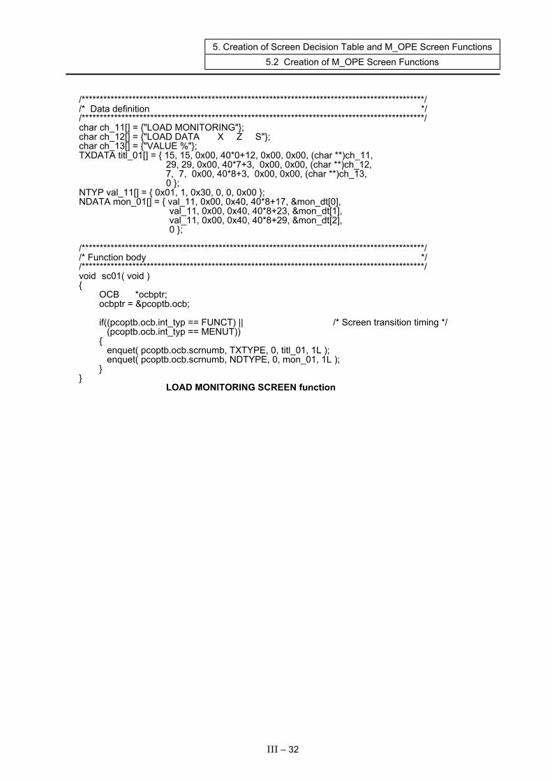
5. Creation of Screen Decision Table and M_OPE Screen Functions 5.2 Creation of M_OPE Screen Functions
/***********************************************************************************************/ /* Data definition */ /***********************************************************************************************/ char ch_11[] = {"LOAD MONITORING"}; char ch_12[] = {"LOAD DATA X Z S"}; char ch_13[] = {"VALUE %"}; TXDATA titl_01[] = { 15, 15, 0x00, 40*0+12, 0x00, 0x00, (char **)ch_11, 29, 29, 0x00, 40*7+3, 0x00, 0x00, (char **)ch_12, 7, 7, 0x00, 40*8+3, 0x00, 0x00, (char **)ch_13, 0 }; NTYP val_11[] = { 0x01, 1, 0x30, 0, 0, 0x00 }; NDATA mon_01[] = { val_11, 0x00, 0x40, 40*8+17, &mon_dt[0], val_11, 0x00, 0x40, 40*8+23, &mon_dt[1], val_11, 0x00, 0x40, 40*8+29, &mon_dt[2], 0 }; /***********************************************************************************************/ /* Function body */ /***********************************************************************************************/ void sc01( void ) { OCB *ocbptr; ocbptr = &pcoptb.ocb; if((pcoptb.ocb.int_typ == FUNCT) || /* Screen transition timing */ (pcoptb.ocb.int_typ == MENUT)) { enquet( pcoptb.ocb.scrnumb, TXTYPE, 0, titl_01, 1L ); enquet( pcoptb.ocb.scrnumb, NDTYPE, 0, mon_01, 1L ); } } LOAD MONITORING SCREEN function
III – 32
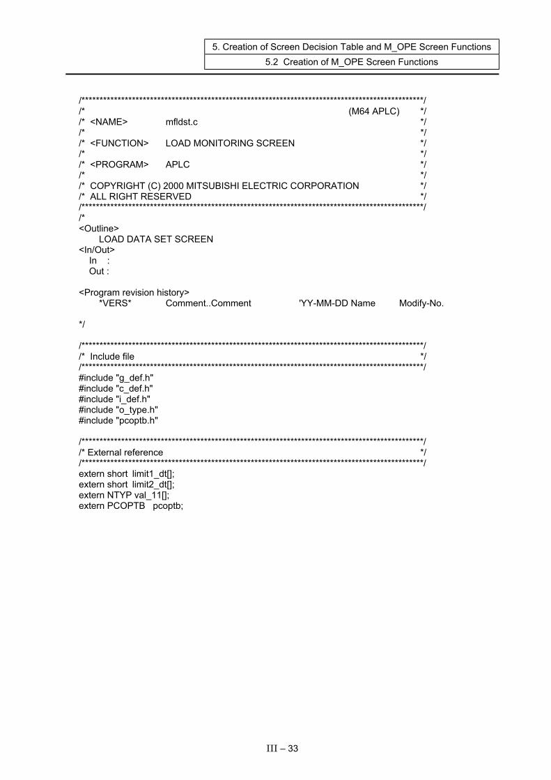
5. Creation of Screen Decision Table and M_OPE Screen Functions 5.2 Creation of M_OPE Screen Functions
/***********************************************************************************************/ /* (M64 APLC) */ /* <NAME> mfldst.c */ /* */ /* <FUNCTION> LOAD MONITORING SCREEN */ /* */ /* <PROGRAM> APLC */ /* */ /* COPYRIGHT (C) 2000 MITSUBISHI ELECTRIC CORPORATION */ /* ALL RIGHT RESERVED */ /***********************************************************************************************/ /* <Outline> LOAD DATA SET SCREEN <In/Out> In : Out : <Program revision history> *VERS* Comment..Comment 'YY-MM-DD Name Modify-No. */ /***********************************************************************************************/ /* Include file */ /***********************************************************************************************/ #include "g_def.h" #include "c_def.h" #include "i_def.h" #include "o_type.h" #include "pcoptb.h" /***********************************************************************************************/ /* External reference */ /***********************************************************************************************/ extern short limit1_dt[]; extern short limit2_dt[]; extern NTYP val_11[]; extern PCOPTB pcoptb;
III – 33

5. Creation of Screen Decision Table and M_OPE Screen Functions 5.2 Creation of M_OPE Screen Functions
/***********************************************************************************************/ /* Data definition */ /***********************************************************************************************/ char ch_t21[] = {"LOAD DATA SET"}; char ch_t22[] = {"LOAD DATA X Z S" }; char ch_t23[] = {"1 LIMIT1 %"}; char ch_t24[] = {"2 LIMIT2 %"}; TXDATA titl_02[] = { 13, 13, 0x00, 40*0+12, 0x00, 0x00, (char **)ch_t21, 27, 27, 0x00, 40*6+3, 0x00, 0x00, (char **)ch_t22, 10, 10, 0x00, 40*7+3, 0x00, 0x00, (char **)ch_t23, 10, 10, 0x00, 40*8+3, 0x00, 0x00, (char **)ch_t24, 0 }; NDATA set_1x[] = { val_11, 0x00, 0x40, 40*7+15, (char *)&limit1_dt[0],0 }; NDATA set_1z[] = { val_11, 0x00, 0x40, 40*7+21, (char *)&limit1_dt[1],0 }; NDATA set_1s[] = { val_11, 0x00, 0x40, 40*7+27, (char *)&limit1_dt[2],0 }; NDATA set_2x[] = { val_11, 0x00, 0x40, 40*8+15, (char *)&limit2_dt[0],0 }; NDATA set_2z[] = { val_11, 0x00, 0x40, 40*8+21, (char *)&limit2_dt[1],0 }; NDATA set_2s[] = { val_11, 0x00, 0x40, 40*8+27, (char *)&limit2_dt[2],0 }; /***********************************************************************************************/ /* Function body */ /***********************************************************************************************/ void mfldst( void ) { long no, limit_temp; if((pcoptb.ocb.int_typ == FUNCT) || /* Screen transition timing */ (pcoptb.ocb.int_typ == MENUT)) { enquet( pcoptb.ocb.scrnumb, TXTYPE, 0, titl_02, 1L ); enquet( pcoptb.ocb.scrnumb, NDTYPE, 0, set_1x, 1L ); enquet( pcoptb.ocb.scrnumb, NDTYPE, 0, set_1z, 1L ); enquet( pcoptb.ocb.scrnumb, NDTYPE, 0, set_1s, 1L ); enquet( pcoptb.ocb.scrnumb, NDTYPE, 0, set_2x, 1L ); enquet( pcoptb.ocb.scrnumb, NDTYPE, 0, set_2z, 1L ); enquet( pcoptb.ocb.scrnumb, NDTYPE, 0, set_2s, 1L ); omakkcb( 0L ); setdisp(); ocurini(1L); cursor(pcoptb.ocb.scrnumb, 0xFE, 0, pcoptb.kcbtblr.cursor, 0); }
III – 34
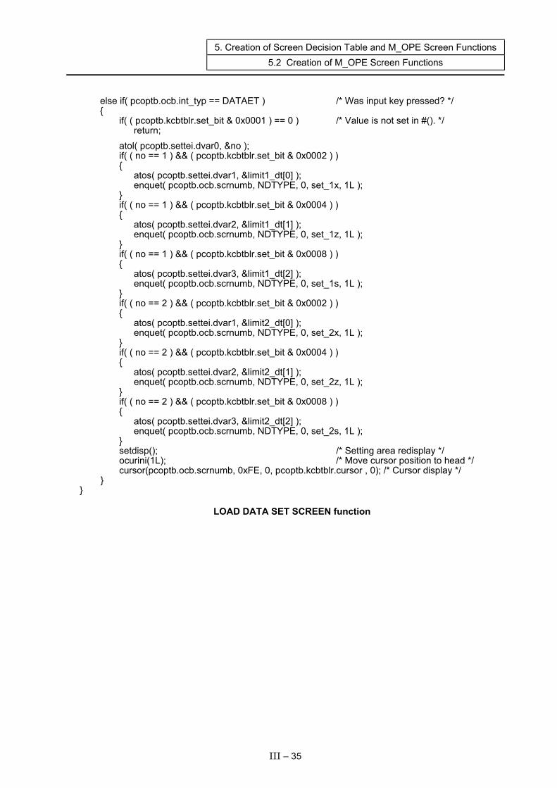
5. Creation of Screen Decision Table and M_OPE Screen Functions 5.2 Creation of M_OPE Screen Functions
else if( pcoptb.ocb.int_typ == DATAET ) /* Was input key pressed? */ { if( ( pcoptb.kcbtblr.set_bit & 0x0001 ) == 0 ) /* Value is not set in #(). */ return; atol( pcoptb.settei.dvar0, &no ); if( ( no == 1 ) && ( pcoptb.kcbtblr.set_bit & 0x0002 ) ) { atos( pcoptb.settei.dvar1, &limit1_dt[0] ); enquet( pcoptb.ocb.scrnumb, NDTYPE, 0, set_1x, 1L ); } if( ( no == 1 ) && ( pcoptb.kcbtblr.set_bit & 0x0004 ) ) { atos( pcoptb.settei.dvar2, &limit1_dt[1] ); enquet( pcoptb.ocb.scrnumb, NDTYPE, 0, set_1z, 1L ); } if( ( no == 1 ) && ( pcoptb.kcbtblr.set_bit & 0x0008 ) ) { atos( pcoptb.settei.dvar3, &limit1_dt[2] ); enquet( pcoptb.ocb.scrnumb, NDTYPE, 0, set_1s, 1L ); } if( ( no == 2 ) && ( pcoptb.kcbtblr.set_bit & 0x0002 ) ) { atos( pcoptb.settei.dvar1, &limit2_dt[0] ); enquet( pcoptb.ocb.scrnumb, NDTYPE, 0, set_2x, 1L ); } if( ( no == 2 ) && ( pcoptb.kcbtblr.set_bit & 0x0004 ) ) { atos( pcoptb.settei.dvar2, &limit2_dt[1] ); enquet( pcoptb.ocb.scrnumb, NDTYPE, 0, set_2z, 1L ); } if( ( no == 2 ) && ( pcoptb.kcbtblr.set_bit & 0x0008 ) ) { atos( pcoptb.settei.dvar3, &limit2_dt[2] ); enquet( pcoptb.ocb.scrnumb, NDTYPE, 0, set_2s, 1L ); } setdisp(); /* Setting area redisplay */ ocurini(1L); /* Move cursor position to head */ cursor(pcoptb.ocb.scrnumb, 0xFE, 0, pcoptb.kcbtblr.cursor , 0); /* Cursor display */ } }
LOAD DATA SET SCREEN function
III – 35
6. Creation of M_OPE Power-on-time Initialize Function and M_OPE F0 Key Initialize Function 6.1 Creation of M_OPE Power-on-time Initialize Function
6. Creation of M_OPE Power-on-time Initialize Function and M_OPE F0 Key Initialize Function
The initialize function to be used when the power is turned ON and when the F0 key is pressed is created. These functions are created under directory SRC\RSV.
6.1 Creation of M_OPE Power-on-time Initialize Function This function is carried out once when the power is turned ON. The M-OPE data is initialized and the version is set, etc. The details of the M_OPE power-on-time initialize function in the sample program are shown below. /***********************************************************************************************/ /* (M64 APLC) */ /* <NAME> mopeini.c */ /* */ /* <FUNCTION> Power-on m_ope initialization */ /* */ /* <PROGRAM> APLC */ /* */ /* COPYRIGHT (C) 1998 MITSUBISHI ELECTRIC CORPORATION */ /* ALL RIGHT RESERVED */ /***********************************************************************************************/ /* <Outline> Initialization of user memory Setting of version <In/Out> In : None Out : None <Program revision history> *VERS* Comment..Comment 'YY-MM-DD Name Modify-No. */
III – 36
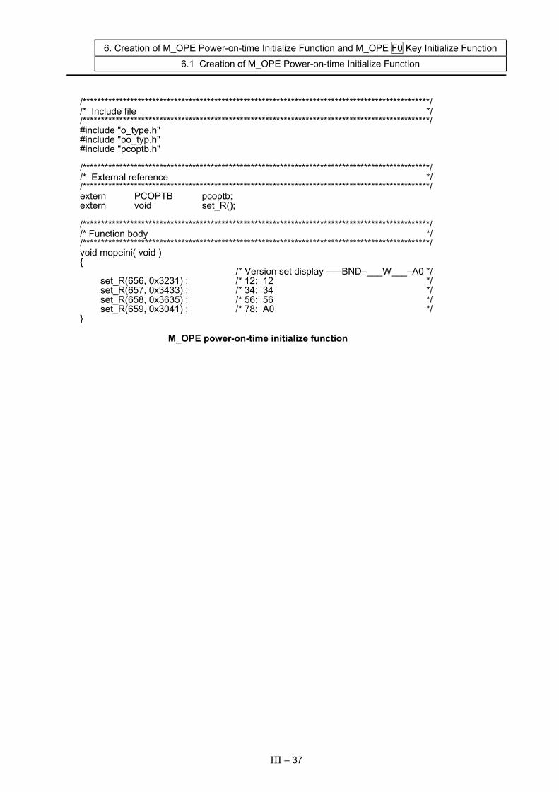
6. Creation of M_OPE Power-on-time Initialize Function and M_OPE F0 Key Initialize Function 6.1 Creation of M_OPE Power-on-time Initialize Function
/***********************************************************************************************/ /* Include file */ /***********************************************************************************************/ #include "o_type.h" #include "po_typ.h" #include "pcoptb.h" /***********************************************************************************************/ /* External reference */ /***********************************************************************************************/ extern PCOPTB pcoptb; extern void set_R(); /***********************************************************************************************/ /* Function body */ /***********************************************************************************************/ void mopeini( void ) { /* Version set display –––BND–___W___–A0 */ set_R(656, 0x3231) ; /* 12: 12 */ set_R(657, 0x3433) ; /* 34: 34 */ set_R(658, 0x3635) ; /* 56: 56 */ set_R(659, 0x3041) ; /* 78: A0 */ } M_OPE power-on-time initialize function
III – 37
6. Creation of M_OPE Power-on-time Initialize Function and M_OPE F0 Key Initialize Function
6.2 Creation of M_OPE F0 Key Initialize Function
6.2 Creation of M_OPE F0 Key Initialize Function
This function is executed each time the F0 key is pressed. The information, etc., in the title screen displayed when the F0 key is pressed is set. The details of the M_OPE F0 key initialize function in the sample program are shown below. /***********************************************************************************************/ /* (M64 APLC) */ /* <NAME> mf0ini.c */ /* */ /* <FUNCTION> F0 selection m_ope initialization */ /* */ /* <PROGRAM> APLC */ /* */ /* COPYRIGHT (C) 1998 MITSUBISHI ELECTRIC CORPORATION */ /* ALL RIGHT RESERVED */ /***********************************************************************************************/ /* <Outline Set function to be called when F0 key is pressed Title screen process <In/Out> In : None Out : None <Program revision history> *VERS* Comment..Comment 'YY-MM-DD Name Modify-No. */ /***********************************************************************************************/ /* Include file */ /***********************************************************************************************/ #include "o_type.h" #include "pcoptb.h" #include "po_typ.h"
III – 38

6. Creation of M_OPE Power-on-time Initialize Function and M_OPE F0 Key Initialize Function
6.2 Creation of M_OPE F0 Key Initialize Function
/***********************************************************************************************/ /* External reference */ /***********************************************************************************************/ extern PCOPTB pcoptb ; extern void mfprmo() ; /* Screen display */ /***********************************************************************************************/ /* Function body */ /***********************************************************************************************/ void mf0ini( void ) { OCB *ocbptr ; /* pcoptb pointer */ ocbptr = &pcoptb.ocb ; /* Set to OCB pointer */ /* Initial screen set */ ocbptr->mnblno = 0 ; ocbptr->menuno = 0 ; /* Set menu No. 1 */ ocbptr->mnfuncp = (long (*)())sc00 ; /* Call function screen display */ ocbptr->mncflag = 0x7a ; /* Selective function call flag */ ocbptr->scrchg |= 0x0001 ; /* Screen changeover flag ON */ } M_OPE F0 key initialize function
III – 39

7. Creation of M_OPE Key Input Pre-process Functions and M_OPE Key Input Post-process Functions 7.1 Creation of M_OPE Key Input Pre-process Function
7. Creation of M_OPE Key Input Pre-process Functions and M_OPE Key Input Post-process Functions
The functions processed before and after the M_OPE screen function when a key is input are created. These functions are created under the directory SRC\RSV.
7.1 Creation of M_OPE Key Input Pre-process Function This function is executed before the M_OPE screen function each time the key is input. This function carries out processes such as clearing of various displayed messages. The details of the M_OPE key input pre-process function in the sample program are shown below. /***********************************************************************************************/ /* (M64 APLC) */ /* <NAME> mkeyin.c */ /* */ /* <FUNCTION> m_ope key input pre-process (before screen process) */ /* */ /* <PROGRAM> APLC */ /* */ /* COPYRIGHT (C) 1998 MITSUBISHI ELECTRIC CORPORATION */ /* ALL RIGHT RESERVED */ /***********************************************************************************************/ /* <Outline> <In/Out> In : None Out : None <Program revision history> *VERS* Comment..Comment 'YY-MM-DD Name Modify-No. */ /***********************************************************************************************/ /* Function body */ /***********************************************************************************************/ /**/ void mkeyin( void ) { } M_OPE key input pre-process function
III – 40
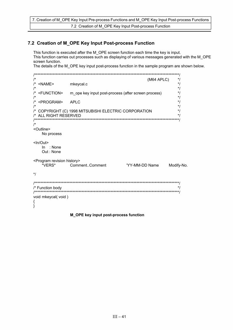
7. Creation of M_OPE Key Input Pre-process Functions and M_OPE Key Input Post-process Functions 7.2 Creation of M_OPE Key Input Post-process Function
7.2 Creation of M_OPE Key Input Post-process Function
This function is executed after the M_OPE screen function each time the key is input. This function carries out processes such as displaying of various messages generated with the M_OPE screen function. The details of the M_OPE key input post-process function in the sample program are shown below. /***********************************************************************************************/ /* (M64 APLC) */ /* <NAME> mkeycal.c */ /* */ /* <FUNCTION> m_ope key input post-process (after screen process) */ /* */ /* <PROGRAM> APLC */ /* */ /* COPYRIGHT (C) 1998 MITSUBISHI ELECTRIC CORPORATION */ /* ALL RIGHT RESERVED */ /***********************************************************************************************/ /* <Outline> No process <In/Out> In : None Out : None <Program revision history> *VERS* Comment..Comment 'YY-MM-DD Name Modify-No. */ /***********************************************************************************************/ /* Function body */ /***********************************************************************************************/ void mkeycal( void ) { } M_OPE key input post-process function
III – 41
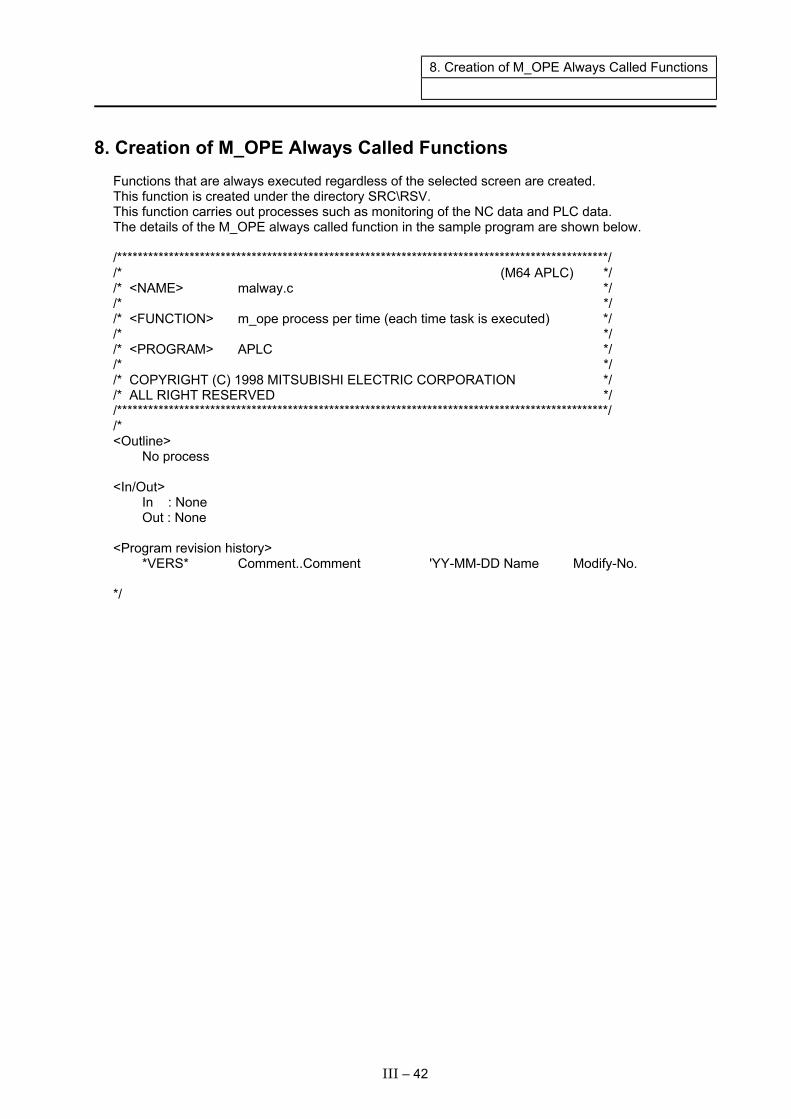
8. Creation of M_OPE Always Called Functions
8. Creation of M_OPE Always Called Functions Functions that are always executed regardless of the selected screen are created. This function is created under the directory SRC\RSV. This function carries out processes such as monitoring of the NC data and PLC data. The details of the M_OPE always called function in the sample program are shown below. /***********************************************************************************************/ /* (M64 APLC) */ /* <NAME> malway.c */ /* */ /* <FUNCTION> m_ope process per time (each time task is executed) */ /* */ /* <PROGRAM> APLC */ /* */ /* COPYRIGHT (C) 1998 MITSUBISHI ELECTRIC CORPORATION */ /* ALL RIGHT RESERVED */ /***********************************************************************************************/ /* <Outline> No process <In/Out> In : None Out : None <Program revision history> *VERS* Comment..Comment 'YY-MM-DD Name Modify-No. */
III – 42

8. Creation of M_OPE Always Called Functions
/***********************************************************************************************/ /* External reference */ /***********************************************************************************************/ extern short mon_dt[]; extern long ddbrd(); /***********************************************************************************************/ /* Function body */ /***********************************************************************************************/ void malway( void ) { long sts; long ddbbf = 0; sts = ddbrd( 27, 328, 2, 0, 1, 0, &ddbbf ); /* X axis Load */ mon_dt[ 0 ] = (short)ddbbf; ddbbf = 0; sts = ddbrd( 27, 328, 2, 0, 2, 0, &ddbbf ); /* Z axis Load */ mon_dt[ 1 ] = (short)ddbbf; ddbbf = 0; sts = ddbrd( 26, 8988, 2, 0, 0, 0, &ddbbf ); /* S axis Load */ mon_dt[ 2 ] = (short)ddbbf; } M_OPE always called function
III – 43
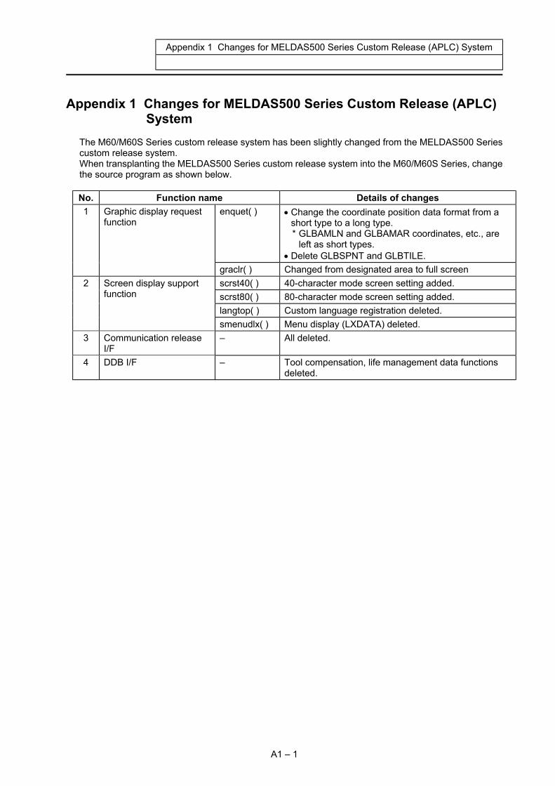
Appendix 1 Changes for MELDAS500 Series Custom Release (APLC) System
Appendix 1 Changes for MELDAS500 Series Custom Release (APLC) System
The M60/M60S Series custom release system has been slightly changed from the MELDAS500 Series custom release system. When transplanting the MELDAS500 Series custom release system into the M60/M60S Series, change the source program as shown below. No. Function name Details of changes
enquet( ) • Change the coordinate position data format from a short type to a long type. * GLBAMLN and GLBAMAR coordinates, etc., are
left as short types. • Delete GLBSPNT and GLBTILE.
1 Graphic display request function
graclr( ) Changed from designated area to full screen scrst40( ) 40-character mode screen setting added. scrst80( ) 80-character mode screen setting added. langtop( ) Custom language registration deleted.
2 Screen display support function
smenudlx( ) Menu display (LXDATA) deleted. 3 Communication release
I/F – All deleted.
4 DDB I/F – Tool compensation, life management data functions deleted.
A1 – 1
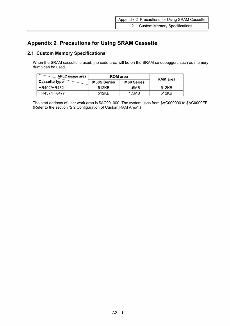
Appendix 2 Precautions for Using SRAM Cassette 2.1 Custom Memory Specifications
Appendix 2 Precautions for Using SRAM Cassette 2.1 Custom Memory Specifications
When the SRAM cassette is used, the code area will be on the SRAM so debuggers such as memory dump can be used.
ROM area APLC usage area Cassette type M60S Series M60 Series
RAM area
HR402/HR432 512KB 1.5MB 512KB HR437/HR/477 512KB 1.5MB 512KB
The start address of user work area is $AC001000. The system uses from $AC000000 to $AC0000FF. (Refer to the section "2.2 Configuration of Custom RAM Area".)
A2 – 1

Appendix 2 Precautions for Using SRAM Cassette 2.2 Configuration of Custom RAM Area
2.2 Configuration of Custom RAM Area
����������������������������������������������������������������������������������������������������������������������������������������������������������������������������������������������������������������������������������������������������������������������������������������������������������������������������������������������������������������������������������������������������������������������������������������������������������������������������������������������������������������������������������������������������������������������������������������������������������������������������������������������������������������������������������������������������������������������������������������������������������������������������������������������������������������������������������������������������������������������������������������������������������������������������������������������������������������������������������������������������������������������������������������������������������������������������������������������������������������������������������������������������������������������������������������������������������������������������������������������������������������������������������������������������������������������������
$AC001000
During RAM operation designation
Reserve for system
is the entry table, and is used for setting the address information for calling or starting the C language module, etc.
����������������������������������������������������������������������������������������
User program area
������������������������������������������������������������������������������������������������������������������������������������������������������������������������������������������������������������������������������������������������������������������������������������������������������������������������������������������������������������������������������������������������������������
User work area
$AC080000
Work area
(512KB)
����������������������������������������������������������������������������������������
$AC200000
Code area
(1.5MB) (M60 only) ��������������������������������������������������������������������������������������$AC100000
$AC180000
512KB
(M60/M60S Series)
$AC000000
A2 – 2
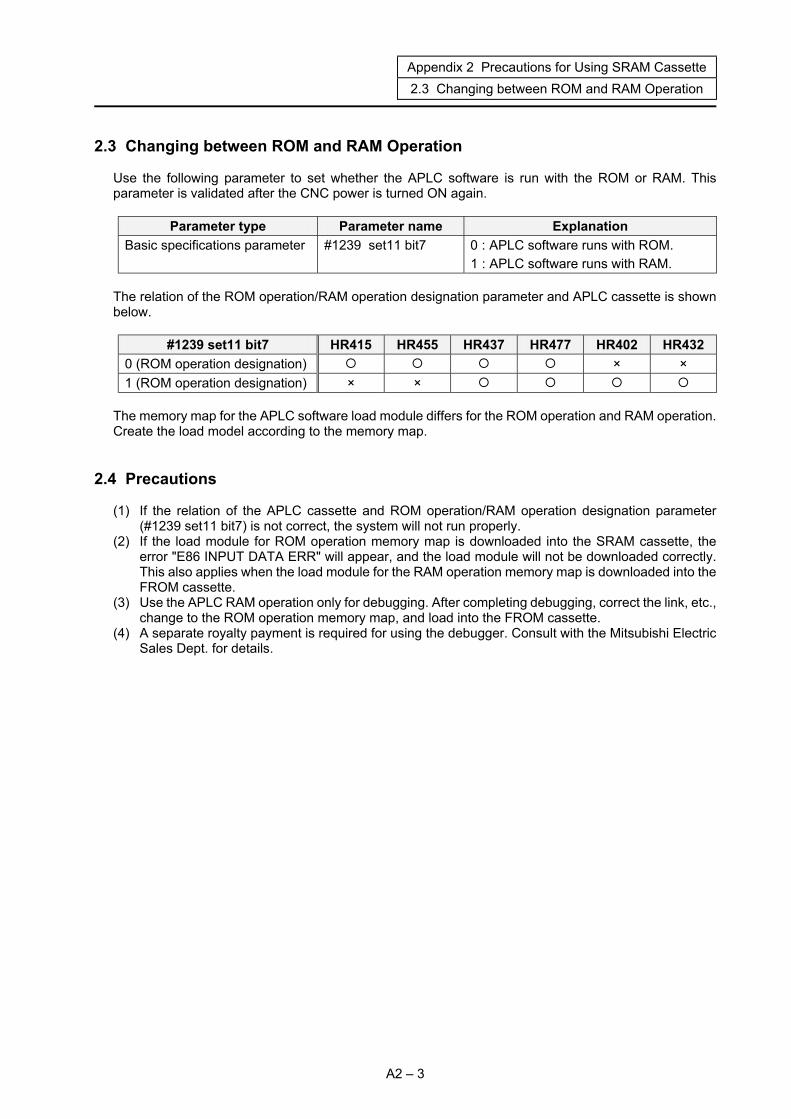
Appendix 2 Precautions for Using SRAM Cassette 2.3 Changing between ROM and RAM Operation
2.3 Changing between ROM and RAM Operation Use the following parameter to set whether the APLC software is run with the ROM or RAM. This parameter is validated after the CNC power is turned ON again.
Parameter type Parameter name Explanation Basic specifications parameter #1239 set11 bit7 0 : APLC software runs with ROM.
1 : APLC software runs with RAM. The relation of the ROM operation/RAM operation designation parameter and APLC cassette is shown below.
#1239 set11 bit7 HR415 HR455 HR437 HR477 HR402 HR432 0 (ROM operation designation) × × 1 (ROM operation designation) × ×
The memory map for the APLC software load module differs for the ROM operation and RAM operation. Create the load model according to the memory map.
2.4 Precautions (1) If the relation of the APLC cassette and ROM operation/RAM operation designation parameter
(#1239 set11 bit7) is not correct, the system will not run properly. (2) If the load module for ROM operation memory map is downloaded into the SRAM cassette, the
error "E86 INPUT DATA ERR" will appear, and the load module will not be downloaded correctly. This also applies when the load module for the RAM operation memory map is downloaded into the FROM cassette.
(3) Use the APLC RAM operation only for debugging. After completing debugging, correct the link, etc., change to the ROM operation memory map, and load into the FROM cassette.
(4) A separate royalty payment is required for using the debugger. Consult with the Mitsubishi Electric Sales Dept. for details.
A2 – 3

Revision history
Sub- No. Date of revision Revision details
E February 2003 First edition created.
Notice
Every effort has been made to keep up with software and hardware revisions in the contents described in this manual. However, please understand that in some unavoidable cases simultaneous revision is not possible. Please contact your Mitsubishi Electric dealer with any questions or comments regarding the use of this product.
Duplication Prohibited This instruction manual may not be reproduced in any form, in part or in whole, without written permission from Mitsubishi Electric Corporation.
2003 MITSUBISHI ELECTRIC CORPORATION ALL RIGHTS RESERVED

BNP-B2217E(ENG)
M60 Series
008-249
(0302)MEE
Specifications subject to change without notice.Printed in Japan on recycled paper.
MITSUBISHI ELECTRIC CORPORATION HEAD OFFICE : MITSUBISHI DENKI BLDG., 2-2-3, MARUNOUCHI, CHIYODA-KU, TOKYO 100-8310, JAPAN
MODEL
Manual No.
MODELCODE