cnc 8050 oem - fagor automation · 4.4.3.1 machine reference setting ... 10.3 variables associated...
TRANSCRIPT

FAGOR 8050 CNC
INSTALLATION MANUAL
Ref. 9701 (in)

FAGOR AUTOMATION S. Coop. keeps informed all thosecustomers who request it about new features implemented onto theFAGOR 8050 CNC.
This way, the customer may request anynew features he may wishto integrate into his own machine.
To do this, simply send us your full company address as well as thereference numbers (model and serial number) of the various CNCmodels you have.
Please note that some of the features described in this manual mightnot be implemented in the software version that you just obtained.
The features dependent on the software version are:
Mill Model Lathe Model
Tool life monitoring Tool life monitoringProbing canned cycle Probing canned cyclesDNC DNCProfile editor Profile EditorSoftware for 4 or 6 axes Software for 4 or 6 axesIrregular pockets (with islands) C axisDigitizingSolid graphicsRigid TappingTracing
The information described in this manual may be subject to variationsdue to technical modifications.
FAGOR AUTOMATION, S.Coop. Ltda. reserves the right to modifythe contents of the manual without prior notice.

When purchasing a FAGOR 8050 GP CNC the following considerationsmust taken:
* This model is based on the FAGOR 8050 M CNC (Mill model).* It is missing some of the features available at the FAGOR 8050 MCNC.
The list below indicates those features missing with respect to the Millmodel CNC as well as the software options available for this model (GP).
Features not available Software options
Electronic threading (G33) Software for 4 or 6 axesTool magazine management DNCMachining canned cycles (G8x) Rigid tapping (G84)Multiple machining cycles (G6x) Tool radius compensationProbing canned cycles (G40, G41, G42)Tool life monitoring Profile editorIrregular pockets (with islands)DigitizingSolid GraphicsTracing

INDEX
Section Page
New features and modifications (M model)New features and modifications (T model)
INTRODUCTION
Declaration of Conformity .............................................................................................. 3Safety Conditions ............................................................................................................ 4Warranty Terms ............................................................................................................... 7Material Returning Terms ............................................................................................... 8Additional Remarks ......................................................................................................... 9Fagor Documentation for the 8050 CNC ........................................................................ 11Manual Contents ............................................................................................................. 12
Chapter 1 CONFIGURATION OF THE FAGOR 8050 CNC
1.1 Structure of the 8050 CNC .............................................................................................. 11.2 Central unit ...................................................................................................................... 21.2.1 Dimensions and installation ............................................................................................ 51.2.2 Power supply module ...................................................................................................... 61.2.2.1 Element description ......................................................................................................... 61.2.3 CPU module .................................................................................................................... 81.2.3.1 Element description ......................................................................................................... 91.2.3.2 Connectors and connections ........................................................................................... 101.2.4 Axes module .................................................................................................................... 221.2.4.1 Element description ......................................................................................................... 231.2.4.2 Connectors and connections ........................................................................................... 241.2.5 I/O module ....................................................................................................................... 321.2.5.1 Element description ......................................................................................................... 331.2.5.2 Connectors and connections ........................................................................................... 341.2.6 Fan module ...................................................................................................................... 361.2.6.1 Element description ......................................................................................................... 361.2.6.2 Connectors ....................................................................................................................... 361.2.7 I/O and Tracing module ................................................................................................... 371.2.7.1 Element description ......................................................................................................... 381.2.7.2 Connectors and connections ........................................................................................... 391.3 Monitor/keyboard ........................................................................................................... 421.3.1 Element description ......................................................................................................... 431.3.2 Connectors and connections ........................................................................................... 451.3.3 Dimensions of the monitor/keyboard (mm)..................................................................... 461.3.4 Monitor/Keyboard enclosures (mm) ................................................................................ 481.4 Operator panel ................................................................................................................. 501.4.1 Element description ......................................................................................................... 501.4.2 Connectors and connections ........................................................................................... 501.4.3 Dimensions of the operator panel (mm)........................................................................... 51

Chapter 2 POWER AND MACHINE CONNECTION
2.1 Power connection ............................................................................................................. 12.2 Machine connection ......................................................................................................... 22.2.1 General considerations ..................................................................................................... 22.2.2 Digital outputs .................................................................................................................. 52.2.3 Digital inputs .................................................................................................................... 62.2.4 Analog outputs ................................................................................................................. 72.2.5 Analog inputs ................................................................................................................... 72.3 Start up .............................................................................................................................. 82.3.1 General considerations ..................................................................................................... 83.3.2 Precautions ....................................................................................................................... 82.3.3 Connection ....................................................................................................................... 92.3.4 Machine parameter setting ............................................................................................... 92.3.5 Adjustment of the machine parameters for the axes ......................................................... 102.3.6 Machine reference point adjustment for each axis (home) ............................................... 112.3.7 Software travel limits for the axes (soft limits) ................................................................. 122.3.8 Adjustment of the drift (offset) and maximum feedrate (G00) .......................................... 122.3.9 Connection of the emergency input and output ............................................................... 14
Chapter 3 MACHINE PARAMETERS
3.1 Introduction ...................................................................................................................... 13.2 Operation with parameter tables ....................................................................................... 33.3 Machine parameter setting ............................................................................................... 43.3.1 General machine parameters ............................................................................................. 53.3.2 Machine parameters for the axes ...................................................................................... 273.3.3 Spindle machine parameters ............................................................................................. 493.3.3.1 Machine parameters for main spindle ............................................................................... 493.3.3.2 Machine parameters for the second spindle ..................................................................... 613.3.3.3 Machine parameters for auxiliary spindle ........................................................................ 733.3.4 Machine parameters for the serial ports ............................................................................ 753.3.5 Machine parameters for the PLC ...................................................................................... 783.3.6 Miscellaneous (M) function table .................................................................................... 803.3.7 Leadscrew error compensation table ................................................................................ 823.3.8 Cross compensation parameter table ................................................................................ 84
Chapter 4 CONCEPT SUBJECTS
4.1 Axes and coordinate systems ............................................................................................ 14.1.1 Nomenclature of the axes ................................................................................................. 14.1.2 Selection of the axes ......................................................................................................... 34.1.3 Gantry axes. coupled and synchonized axes .................................................................... 54.1.4 Relationship between the axes and the jog keys .............................................................. 74.2 Feedback systems ............................................................................................................. 84.2.1 Counting speed limitations .............................................................................................. 94.2.2 Resolution ........................................................................................................................ 104.3 Axis setting ....................................................................................................................... 154.3.1 Servo drive setting ............................................................................................................ 164.3.2 Gain setting....................................................................................................................... 174.3.3 Proportional gain setting .................................................................................................. 184.3.4 Feed-forward gain setting ................................................................................................. 204.3.5 Derivative / AC-forward gain setting ................................................................................ 214.3.6 Leadscrew backlash compensation................................................................................... 224.3.7 Leadscrew error compensation ......................................................................................... 23
Section Page

Section Page
4.4 Reference systems ............................................................................................................. 254.4.1 Reference points ............................................................................................................... 254.4.2 Machine reference search ................................................................................................. 264.4.2.1 Machine reference search on gantry axes ......................................................................... 274.4.3 Setting on systems without semi-absolute feedback ........................................................ 284.4.3.1 Machine reference setting ................................................................................................ 284.4.3.2 Considerations .................................................................................................................. 294.4.4 Setting on systems with semi-absolute feedback ............................................................. 304.4.4.1 Scale offset setting ............................................................................................................ 304.4.4.2 Considerations .................................................................................................................. 314.4.5 Axis travel limits (software limits) .................................................................................... 324.5 Unidirectional approach ................................................................................................... 334.6 Transferring auxiliary M, S, T functions .......................................................................... 344.6.1 Transferring M, S, T using the AUXEND signal ............................................................... 374.6.2 Transferring the miscellaneous M functions without the AUXEND signal ..................... 384.7 Spindle .............................................................................................................................. 394.7.1 Spindle types .................................................................................................................... 414.7.2 Spindle speed (S) control .................................................................................................. 424.7.3 Spindle speed range change ............................................................................................. 444.7.3.1 Automatic spindle range change controlled by PLC ....................................................... 454.7.3.2 Automatic spindle range change when working with M19 .............................................. 464.7.4 Spindle in closed loop ...................................................................................................... 474.7.4.1 Calculating spindle resolution ......................................................................................... 474.7.4.2 Gain setting ...................................................................................................................... 484.7.4.3 Proportional gain setting .................................................................................................. 494.7.4.4 Feed-forward gain setting ................................................................................................. 504.7.4.5 Derivative / AC-forward gain setting ................................................................................ 514.7.4.6 Machine reference setting ................................................................................................ 524.7.4.7 Considerations .................................................................................................................. 534.8 Treatment of emergency signals ....................................................................................... 544.8.1 Emergency signals ............................................................................................................ 544.8.2 CNC treatment of emergency signals ............................................................................... 55
4.8.3 PLC treatment of emergency signals ................................................................................ 56
Chapter 5 INTRODUCTION TO THE PLC
5.1 PLC resources .................................................................................................................. 35.2 PLC program execution .................................................................................................... 45.3 Modular program structure ............................................................................................... 115.3.1 First cycle module (CY1) .................................................................................................. 115.3.2 Main module (PRG) .......................................................................................................... 115.3.3 Periodic execution module (PEt) ...................................................................................... 125.3.4 Priority in the execution of PLC modules ........................................................................ 13

Chapter 6 PLC RESOURCES
6.1 Inputs ................................................................................................................................ 16.2 Outputs ............................................................................................................................. 16.3 Marks ................................................................................................................................ 26.4 Registers ........................................................................................................................... 46.5 Timers ............................................................................................................................... 56.5.1 Timer operating modes ..................................................................................................... 86.5.1.1 Monostable mode. Input TG1........................................................................................... 86.5.1.2 Activation delay mode. Input TG2 ................................................................................... 106.5.1.3 Deactivation delay mode. Input TG3 ............................................................................... 126.5.1.4 Signal limiting mode. Input TG4 ..................................................................................... 146.6 Counters ............................................................................................................................ 166.6.1 The operating mode of a counter ...................................................................................... 19
Chapter 7 PLC PROGRAMMING
7.1 Structure of a module ........................................................................................... 47.2 Directing instructions .......................................................................................... 67.3 Consulting instructions ....................................................................................... 107.3.1 Simple consulting instructions ............................................................................ 107.3.2 Flank detection consulting instructions .............................................................. 117.3.3 Comparative consulting instructions .................................................................. 127.4 Operators .............................................................................................................. 137.5 Action instructions .............................................................................................. 157.5.1 Binary action instructions ................................................................................... 167.5.1.1 Assignment binary action instructions ................................................................ 167.5.1.2 Conditioned binary action instructions .............................................................. 177.5.2 Sequence breaking action instructions ............................................................... 187.5.3 Arithmetic action instructions ............................................................................. 207.5.4 Logic action instructions ..................................................................................... 247.5.5 Specific action instructions ................................................................................. 267.6 Summary of PLC programming instructions ....................................................... 29
Chapter 8 CNC-PLC COMMUNICATION
8.1 Auxiliary M, S, T functions ................................................................................. 28.1.1 Transferring auxiliary M, S, T functions ............................................................. 58.1.1.1 Transferring M, S, T using the AUXEND signal .................................................. 68.1.1.2 Transferring the auxiliary M function without the AUXEND signal .................. 78.2 Displaying messages, errors and pages on the CNC ............................................ 88.3 Access from the CNC to the program and PLC resources .................................... 108.4 Access from a computer, via DNC, to PLC resources .......................................... 10
Chapter 9 CNC LOGIC INPUTS AND OUTPUTS
9.1 General logic inputs ............................................................................................ 29.2 Axis logic inputs ................................................................................................. 99.3 Spindle logic inputs ............................................................................................ 159.4 Key inhibiting logic inputs ................................................................................. 229.5 General logic outputs .......................................................................................... 269.6 Axis logic outputs ............................................................................................... 349.7 Spindle logic outputs .......................................................................................... 369.8 Logic outputs of key status ................................................................................. 37
Section Page

Chapter10 ACCESS TO INTERNAL CNC VARIABLES
10.1 Variables associated with tools ........................................................................... 310.2 Variables associated with zero offsets ................................................................. 610.3 Variables associated with machine parameters ................................................... 710.4 Variables associated with work zones ................................................................. 810.5 Variables associated with feedrates ..................................................................... 910.6 Variables associated with position coordinates .................................................. 1110.7 Variables associated with the main spindle ......................................................... 1210.8 Variables associated with the second spindle ..................................................... 1610.9 Variables associated with global and local arithmetic parameters ...................... 1910.10 Other variables ..................................................................................................... 20
Chapter 11 AXES CONTROLLED FROM THE PLC
11.1 Considerations ..................................................................................................... 211.2 Blocks which can be executed from the PLC ...................................................... 411.3 Control of the PLC program from the CNC ......................................................... 6
Chapter 12 PLC PROGRAMMING EXAMPLE
APPENDICES
A Technical characteristics of the 8050 CNC ......................................................... 2B Recommended probe connection circuits ........................................................... 9C PLC programming instructions ........................................................................... 10D Internal CNC variables ........................................................................................ 16E CNC logic inputs and outputs ............................................................................. 21F Conversion table for S output in 2-digit BCD code ............................................ 28G Key codes ............................................................................................................ 29H Machine parameter setting .................................................................................. 34I Maintenance ........................................................................................................ 54
Section Page

New Features (M) - 1
NEW FEATURES AND MODIFICATIONS(Mill model)
Date: June 1992 Software Version: 7.01 and newer
FEATURE AFFECTED MANUAL AND CHAPTERS
GP Model All Manuals 1st page
Reception of Autocad drawings Dedicated Manual. Supplied with the software
Auxiliary Spindle / Live tool Installation Manual Chap. 3, Chap. 9, AppendixProgramming Manual Chap. 5, Chap. 13
Tracing Installation Manual Chap. 1, Chap. 3Program. Manual Chap. 5, Chap. 14, Chap. 16, Appen.
Profile Editor Operating Manual Chap. 4
Interactive Editor Operating Manual Chap. 4
“TEACH-IN” Editing Operating Manual Chap. 4
Software for 4 or 6 axes Installation Manual Chap.4, Chap. 9, Chap. 10, Appen.Programming Manual Chap.3, Chap. 13
Axes Controlled from the PLC Installation Manual Chap. 3, Chap. 11
Storing of EEPROM memory contentsinto an EPROM memory Operating Manual Chap.7
Tool calibration with a probe in JOG mode Installation Manual Chap. 3Operating Manual Chap. 5
Interruption Subroutines (4 inputs) Installation Manual Chap. 3, Chap. 9, Appendix
Logic Analyzer for the PLC Installation Manual Chap. 7Operating Manual Chap. 9
AC- forward Installation Manual Chap.3
PLC Monitoring in JOG mode Operating Manual Chap. 5
Execution time Estimates Operating Manual Chap. 3
Part program storing in EEPROM memory Installation Manual Chap. 3Operating Manual Chap. 7, Chap. 12
Three cross compensation tables Installation Manual Chap. 3, AppendixOperating Manual Chap. 11
Axes jogging when setting leadscrew and crosscompensation tables Operating Manual Chap. 11
Subroutine associated with the tools Installation Manual Chap. 3
Possibility to FIND TEXT in theBLOCK SELECTION option Operating Manual Chap. 3
More double and triple size characters Operating Manual Chap. 10
Programming of the ERROR instructionby parameter Programming Manual Chap. 14
Variables to access the rotation center:ROTPF and ROTPS Programming Manual Chap. 13, Appendix

2- New features (M)
FEATURE AFFECTED MANUAL AND CHAPTERS
Variables to access the tracing probe: Installation Manual Chap. 10, AppendixDEFLEX, DEFLEY and DEFLEZ Programming Manual Chap. 13, Appendix
General logic output indicating the statusof the axes positioning loop: LOPEN Installation Manual Chap. 9, Appendix
PLC. Initialize a group of registers Operating Manual Chap. 9
PLC. New instructions Installation Manual Chap. 7
PLC. 200 symbols Installation Manual Chap. 7
New possibilities in irregular pockets(with islands) Programming Manual Chap. 11
Connector X7 of the AXES module Installation Manual Chap. 1
Support of the FAGOR Floppy disc unit Installation Manual Chap. 1, Chap. 3
Make the tool change cycle more flexible Installation Manual Chap. 3
Improved error processing Operating Manual Chap. 1
Date: April 1993 Software Version: 7.06 and newer
FEATURE AFFECTED MANUAL AND CHAPTERS
Limitless rotary axes Installation Manual Chap. 3
Positioning axes in G01 Programming Manual Chap. 6
Reference point shift Installation Manual Chap. 3, Chap. 4
Work zone variables (R/W) from PLC Installation Manual Chap. 10, AppendixProgramming Manual Appendix
Possibility to abort the PLC channel Installation Manual Chap. 9 Appendix
Movement until contact Installation Manual Chap. 3, Cap. 11Programming Manual Chap. 6, Appendix
Boring Mill graphics Installation Manual Chap. 3
"WBUF" programmable without parameters Programming Manual Chap. 14
Date: July 1993 Software Version: 7.07 and newer
FEATURE AFFECTED MANUAL AND CHAPTERS
The GP model offers optional Tool radiuscompensation (G40, G41, G42)
Logic outputs of the key status Installation manual Chap. 9

New Features (M) - 3
Date: January 1994 Software Version: 9.01 and newer
FEATURE AFFECTED MANUAL AND CHAPTERS
Tool base or tool tip position display Installation manual Chap. 3
Measurement in graphics via cursor Operating manual Chap. 3
Two ways for tool calibration Operating manual Chap. 5(manual and probe)
Treatment of coded Io signals Installation manual Chap. 3
Possibility to store PLC errors and Installation manual Chap. 3messages in EEPROM memory Operating manual Chap. 7
"Program in EEPROM" indicator Operating manual Chap. 7
"Program in execution" indicator Operating manual Chap. 7
G50. Controlled corner rounding Installation manual Chap. 3, Chap. 11Programming manual Chap. 5, 7, Appendix
Feedrate per revolution (G95) for Installation manual Chap. 11axes controlled via PLC
Concentric roughing of irregular Programming manual Chap. 11pockets (with islands)
G93 when defining the profile Programming manual Chap. 11of an irregular pocket
Manual; one, two and three-dimensional Installation manual Chap. 9, Appendixtracing and digitizing cycles Programming manual Chap. 5, 16, Appendix
New tracing/digitizing cycles Programming manual Chap. 16
Display of deflection and correction Operating manual Chap. 3, 5factor for the tracing probe
Infinite program execution from a PC Operating manual Chap. 8
Multi-disk infinite program in Operating manual Chap. 8Floppy Disk Unit
Multi-disk digitizing in Floppy Disk Unit Operating manual Chap. 8.
Date: May 1994 Software Version: 9.03 and newer
FEATURE AFFECTED MANUAL AND CHAPTERS
Anticipation time, for punching Installation manual Chap. 3, 9, Appendix
Variables: TPOS(X-C), TPOSS, FLWES Installation manual Chap. 10, Appendix
M19 speed modification via PLC Installation manual Chap. 9, Appendix.
G75 and G76 moves at 100% of F Programming manual Chap. 10

4- New features (M)
Date: December 1994 Software Version: 9.06 and newer
FEATURE AFFECTED MANUAL AND CHAPTERS
Third work zone Installation manual Chap. 10, AppendixProgramming manual Chap. 3, 13, Appendix
For easier operation without monitor, the Installation manual Chap. 3default values of parameters: PROTOCOL (1)and POWDNC (yes) have been changed
Date: February 1995 Software Version: 9.07 and newer
FEATURE AFFECTED MANUAL AND CHAPTERS
If while searching "coded" home, the DECEL* Installation manual Chap. 4signal of the axis goes high, the homing directionis reversed.
A "T" function with associated subroutine Installation manual Chap. 3may be programmed in a motion block.
The TAFTERS parameter indicates whether the Installation manual Chap. 3"T" function is executed before or after itsassociated subroutine.
Function G53 without motion information cancels Programming manual Chap. 4the active zero offset.
The "M" function table allows interrupting block Installation manual Chap. 3preparation until the "M" starts or ends. Operating manual Chap. 11
Date: October 1995 Software Version: 9.09 and newer
FEATURE AFFECTED MANUAL AND CHAPTERS
M19TYPE (spindle parameter) indicates whether Installation manual Chap. 3or not the spindle is homed every time it switchesfrom open loop to closed loop.
Variables POSS and TPOSS always active Installation manual Chap. 10(whether in open loop or closed loop). Programming manual Chap. 13
Leadscrew compensation tables allow slopes Installation manual Chap. 3of up to ±45º. Operating manual Chap. 11
Date: April 1996 Software Version: 9.10 and newer
FEATURE AFFECTED MANUAL AND CHAPTERS
New spindle related variables RPOSS and RTPOSS Installation manual Chap. 10 and Appendix
Programming manual Chap. 13 and Appendix
Date: July1996 Software Version: 9.11 and newer
FEATURE AFFECTED MANUAL AND CHAPTERS
Machine parameter EXTMULT to be used when Installation manual Chap. 3the feedback system has coded marker pulses (Io).

New Features (M) - 5
Date: May 1996 Software Version: 11.01 and newer
FEATURE AFFECTED MANUAL AND CHAPTERS
CPU TURBO Installation manual Chap. 1 and 3
Look-Ahead Programming manual Chap. 5, 7 and Appendix
3D Irregular pockets (with islands) Programming manual Chap. 11
Possibility to choose beginning and end Installation manual Chap. 3of tool radius compensation. Programming manual Chap. 8
Anticipation signal for each axis Installation manual Chap. 3, 9 and Appendix
High-level block execution from PLC Installation manual Chap. 11
Non-rollover rotary axis now possible Installation manual Chap. 3
Line graphics on GP models
Optional Profile Editor on GP models

New Features (T) - 1
NEW FEATURES AND MODIFICATIONS(Lathe Model)
Date: June 1992 Software Version: 6.01 and newer
FEATURE AFFECTED MANUAL AND CHAPTERS
Reception of Autocad drawings Dedicated Manual. Supplied with the software
C axis Installation Manual Chap. 9, AppendixProgramming Manual Chap. 5, Chap. 6, AppendixOperating Manual Chap. 3, Chap. 6
Auxiliary Spindle / Live tool Installation Manual Chap. 3, Chap. 9, AppendixProgramming Manual Chap. 5, Chap. 11
Profile Editor Operating Manual Chap. 4
Interactive Editor Operating Manual Chap. 4
“TEACH-IN” editing Operating Manual Chap. 4
Software for 2, 4 or 6 axes Installation Manual Chap. 4, Chap. 9, Chap. 10, Appen.Programming Manual Chap. 3, Chap. 11
Axes Controlled from the PLC Installation Manual Chap. 3, Chap. 11
Storing of EEPROM memory contentsin EPROM memory Operating Manual Chap.7
Tool calibration with a probe in JOG mode Installation Manual Chap. 3Operating Manual Chap. 5
Interruption Subroutines (4 inputs) Installation Manual Chap. 3, Chap. 9, Appendix
Logic analyzer for the PLC Installation Manual Chap. 7Operating Manual Chap. 9
AC- forward Installation Manual Chap.3
PLC Monitoring in JOG mode Operating Manual Chap. 5
Execution time estimates Operating Manual Chap. 3
Part-program storing in EEPROM memory Installation Manual Chap. 3Operating Manual Chap. 7, Chap. 12
Three cross compensation tables Installation Manual Chap. 3, AppendixOperating Manual Chap. 11
Axes jogging when setting leadscrew and Operating Manual Chap. 11cross compensation tables
Subroutine associated with the tools Installation Manual Chap. 3
Possibility to FIND TEXT inthe BLOCK SELECTION option Operating Manual Chap. 3

2 - New Features (T)
FEATURE AFFECTED MANUAL AND CHAPTERS
More double and triple size characters Operating Manual Chap. 10
Possibility to select colors for solid graphics Operating Manual Chap. 3
Programming of the ERRORinstruction by parameter Programming Manual Chap.12
General logic output indicating the statusof the axes positioning loop: LOPEN Installation Manual Chap. 9, Appendix
PLC. Initialize a group of registers Operating Manual Chap. 9
PLC. New instructions Installation Manual Chap. 7
PLC. 200 symbols Installation Manual Chap. 7
Finishing pass (G05 or G07) in canned cycles Programming Manual Chap. 9
Connector X7 of the AXES module Installation Manual Chap. 1
Support for the FAGOR floppy disc unit Installation Manual Chap. 1, Chap. 3
Make the tool change cycle flexible Installation Manual Chap. 3
Improved error processing Operating Manual Chap. 1
Date: April 1993 Software Version: 6.06 and newer
FEATURE AFFECTED MANUAL AND CHAPTERS
Limitless rotary axes Installation Manual Chap. 3
Positioning axes in G01 Programming Manual Chap. 6
Reference point shift Installation Manual Chap. 3, Chap. 4
Work zone variables (R/W) from PLC Installation Manual Chap. 10, AppendixProgramming Manual Appendix
Possibility to abort the PLC channel Installation Manual Chap. 9 Appendix
Movement until contact Installation Manual Chap. 3, Cap. 11Programming Manual Chap. 6, Appendix
INCH/MM in Geometry table Operating Manual Chap. 6
"WBUF" programmable without parameters Programming Manual Chap. 12
Date: July 1993 Software Version: 6.07 and newer
FEATURE AFFECTED MANUAL AND CHAPTERS
Logic outputs of the key status Installation manual Chap. 9

New Features (T) - 3
Date: January 1994 Software Version: 8.01 and newer
FEATURE AFFECTED MANUAL AND CHAPTERS
Tool base or tool tip position display Installation manual Chap. 3
Measurement in graphics via cursor Operating manual Chap. 3
Two ways for tool calibration Operating manual Chap. 5(manual and probe)
Treatment of coded Io signals Installation manual Chap. 3
Possibility to store PLC errors and Installation manual Chap. 3messages in EEPROM memory Operating manual Chap. 7
"Program in EEPROM" indicator Operating manual Chap. 7
"Program in execution" indicator Operating manual Chap. 7
G50. Controlled corner rounding Installation manual Chap. 3, Chap. 11Programming manual Chap. 5, 7, Appendix
Feedrate per revolution (G95) for Installation manual Chap. 11axes controlled via PLC
G93 when defining the profile Programming manual Chap. 9of a canned cycle
Infinite program execution from a PC Operating manual Chap. 8
Date: May 1994 Software Version: 8.02 and newer
FEATURE AFFECTED MANUAL AND CHAPTERS
Withdrawal mode selection in canned cycles: Programming manual Chap. 9G68, G69, G81, G82, G84 and G85
Excess material on X and Z on G66, G68: Programming manual Chap. 9and G69 canned cycles
Axis selection in G66 canned cycle Programming manual Chap. 9
G75 and G76 moves at 100% of F Programming manual Chap. 10
Date: July 1994 Software Version: 8.03 and newer
FEATURE AFFECTED MANUAL AND CHAPTERS
Anticipation time, for punching Installation manual Chap. 3, 9, Appendix
Variables: TPOS(X-C), TPOSS, FLWES Installation manual Chap. 10, Appendix
M19 speed modification via PLC Installation manual Chap. 9, Appendix.

4 - New Features (T)
Date: October1994 Software Version: 8.04 and newer
FEATURE AFFECTED MANUAL AND CHAPTERS
Permanent "C" axis Installation manual Chap. 3Programming manual Chap. 6
Date: January 1995 Software Version: 8.06 and newer
FEATURE AFFECTED MANUAL AND CHAPTERS
Third work zone Installation manual Chap. 10, AppendixProgramming manual Chap. 3, 11, Appendix
If while searching "coded" home, the DECEL* Installation manual Chap. 4signal of the axis goes high, the homing directionis reversed.
Date: March 1995 Software Version: 8.07 and newer
FEATURE AFFECTED MANUAL AND CHAPTERS
A "T" function with associated subroutine Installation manual Chap. 3may be programmed in a motion block.
The TAFTERS parameter indicates whether the Installation manual Chap. 3"T" function is executed before or after itsassociated subroutine.
Function G53 without motion information cancels Programming manual Chap. 4the active zero offset.
The "M" function table allows interrupting block Installation manual Chap. 3preparation until the "M" starts or ends. Operating manual Chap. 11
For easier operation without monitor, the Installation manual Chap. 3default values of parameters: PROTOCOL (1)and POWDNC (yes) have been changed.
Date: July 1995 Software Version: 8.08 and newer
FEATURE AFFECTED MANUAL AND CHAPTERS
M19TYPE (spindle parameter) indicates whether Installation manual Chap. 3or not the spindle is homed every time it switchesfrom open loop to closed loop.
Variables POSS and TPOSS always active Installation manual Chap. 10(whether in open loop or closed loop). Programming manual Chap. 11
Leadscrew compensation tables allow slopes Installation manual Chap. 3of up to ±45º. Operating manual Chap. 11
Date: April 1996 Software Version: 8.09 and newer
FEATURE AFFECTED MANUAL AND CHAPTERS
New spindle related variables RPOSS and RTPOSS Installation manual Chap. 10 and AppendixProgramming manual Chap. 13 and Appendix

New Features (T) - 5
Date: July1996 Software Version: 8.10 and newer
FEATURE AFFECTED MANUAL AND CHAPTERS
Machine parameter EXTMULT to be used when Installation manual Chap. 3the feedback system has coded marker pulses (Io).
Date: Sep. 1996 Software Version: 10.01 and newer
FEATURE AFFECTED MANUAL AND CHAPTERS
CPU TURBO Installation manual Chap. 1 and 3
Look-Ahead Programming manual Chap. 5, 7 and Appendix
Possibility to choose beginning and end Installation manual Chap. 3of tool radius compensation. Programming manual Chap. 8
Anticipation signal for each axis Installation manual Chap. 3, 9 and Appendix
High-level block execution from PLC Installation manual Chap. 11
Possibility of non-rollover rotary axes Installation manual Chap. 3
Feedrate per revolution in JOG mode. Installation manual Chap. 3
Possibility of sharing the electronic Installation manual Chap. 3handwheel with any axis.
RESET effective without prior CYCLE STOP. Installation manual Chap. 3
New canned cycles with live tool: Programming manual Chap. 9 and AppendixG60, G61, G62 and G63.
Possibility of final roughing pass in cycles: Programming manual Chap. 9G68, G69, G81, G82, G84 and G85
G83. Tapping canned cycle Programming manual Chap. 9
Possibility of setting the grooving pass Programming manual Chap. 9in canned cycles: G88 and G89.
Possibility of defining a profile in another Programming manual Chap. 9program. For canned cycles: G66, G67 and G69.
2 Spindles Installation manual Chap. 3, 9, 10 and AppendixProgramming manual Chap. 5, 11 and Appendix
Canned cycles in any plane. Programming manual Chap. 9
Tool compensation in any plane Installation manual Chap. 3 and 4Programming manual Chap. 8
Change PC directory from the CNC via DNC Operating manual Chap. 7

Introduction - 1
INTRODUCTION
Atention:Before starting up the CNC, carefully read the instructions of Chapter2 in the Installation Manual.
The CNC must not be powered-on until verifying that the machinecomplies with the "89/392/CEE" Directive.

Introduction - 2

Introduction - 3
DECLARATION OF CONFORMITY
Manufacturer: Fagor Automation, S. Coop.
Barrio de San Andrés s/n, C.P. 20500, Mondragón -Guipúzcoa- (ESPAÑA)
We hereby declare, under our resposibility that the product:
Fagor 8050 CNC
meets the following directives:
SAFETY:
EN 60204-1 Machine safety. Electrical equipment of the machines.
ELECTROMAGNETIC COMPATIBILITY:
EN 50081-2 Emission
EN 55011 Radiated. Class A, Group 1.EN 55011 Conducted. Class A, Group 1.
EN 50082-2 Immunity
EN 61000-4-2 Electrostatic Discharges.EN 61000-4-4 Bursts and fast transients.EN 61000-4-11Voltage fluctuations and Outages.ENV 50140 Radiofrequency Radiated Electromagnetic Fields.ENV 50141 Conducted disturbance induced by radio frequency fields.
As instructed by the European Community Directives on Low Voltage: 73/23/EEC,on Machine Safety 89/392/CEE and 89/336/CEE on Electromagnetic Compatibility.
In Mondragón, on April 1st, 1996

Introduction - 4
SAFETY CONDITIONS
Read the following safety measures in order to prevent damage to personnel, tothis product and to those products connected to it.
This unit must only be repaired by personnel authorized by Fagor Automation.
Fagor Automation shall not be held responsible for any physical or materialdamage derived from the violation of these basic safety regulations.
Precautions against personal damage
Interconnection of modulesUse the connection cables provided with the unit.
Use proper Mains AC power cablesTo avoid risks, use only the Mains AC cables recommended for this unit.
Avoid electrical overloadsIn order to avoid electrical discharges and fire hazards, do not apply electrical voltageoutside the range selected on the rear panel of the Central Unit.
Ground connectionIn order to avoid electrical discharges, connect the ground terminals of all themodules to the main ground terminal. Before connecting the inputs and outputs of thisunit, make sure that all the grounding connections are properly made.
Before powering the unit up, make sure that it is connected to groundIn order to avoid electrical discharges, make sure that all the grounding connectionsare properly made.
Do not work in humid environmentsIn order to avoid electrical discharges, always work under 90% of relative humidity(non-condensing) and 45º C (113º F).
Do not work in explosive environmentsIn order to avoid risks, damage, do no work in explosive environments.
Precautions against product damage
Working environmentThis unit is ready to be used in Industrial Environments complying with the directivesand regulations effective in the European Community
Fagor Automation shall not be held responsible for any damage suffered or causedwhen installed in other environments (residential or homes).
Install the unit in the right placeIt is recommended, whenever possible, to instal the CNC away from coolants,chemical product, blows, etc. that could damage it.
This unit complies with the European directives on electromagnetic compatibility.

Introduction - 5
Nevertheless, it is recommended to keep it away from sources of electromagneticdisturbance such as.- Powerful loads connected to the same AC power line as this equipment.- Nearby portable transmitters (Radio-telephones, Ham radio transmitters).- Nearby radio / TC transmitters.- Nearby arc welding machines- Nearby High Voltage power lines- Etc.
EnclosuresThe manufacturer is responsible of assuring that the enclosure involving the equipmentmeets all the currently effective directives of the European Community.
Avoid disturbances coming from the machine toolThe machine-tool must have all the interference generating elements (relay coils,contactors, motors, etc.) uncoupled.
Use the proper power supplyUse an external regulated 24 Vdc power supply for the inputs and outputs.
Grounding of the power supplyThe zero volt point of the external power supply must be connected to the main groundpoint of the machine.
Analog inputs and outputs connectionIt is recommended to connect them using shielded cables and connecting their shields(mesh) to the corresponding pin (See chapter 2).
Ambient conditionsThe working temperature must be between +5° C and +45° C (41ºF and 113º F)The storage temperature must be between -25° C and 70° C. (-13º F and 158º F)
Monitor enclosureAssure that the Monitor is installed at the distances indicated in chapter 1 from thewalls of the enclosure.
Use a DC fan to improve enclosure ventilation.
Main AC Power SwitchThis switch must be easy to access and at a distance between 0.7 m (27.5 inches) and1.7 m (5.6 ft) off the floor.
Protections of the unit itself
Power Supply ModuleIt carries two fast fuses of 3.15 Amp./ 250V. to protect the mains AC input
Axes moduleAll the digital inputs and outputs have galvanic isolation via optocouplers betweenthe CNC circuitry and the outside.They are protected by an external fast fuse (F) of 3.15 Amp./ 250V. against reverseconnection of the power supply.

Introduction - 6
Input / Output ModuleAll the digital inputs and outputs have galvanic isolation via optocouplers betweenthe CNC circuitry and the outside.They are protected by an external fast fuse (F) of 3.15 Amp./ 250V. against a voltageoverload (greater than 33Vdc) and against reverse connection of the power supply.
Input / Output and Tracing ModuleAll the digital inputs and outputs have galvanic isolation via optocouplers betweenthe CNC circuitry and the outside.They are protected by an external fast fuse (F) of 3.15 Amp./ 250V. against a voltageoverload (greater than 33Vdc) and against reverse connection of the power supply.
Fan ModuleIt carries 1 or 2 external fuses depending on modelThe fuses are fast (F), of 0.4 Amp./ 250V. to protect the fans.
MonitorThe type of protection fuse depends on the type of monitor. See the identificationlabel of the unit itself.
Precautions during repair
Do not manipulate the inside of the unitOnly personnel authorized by Fagor Automation may manipulate theinside of this unit.
Do not manipulate the connectors with the unit connected to ACpower.Before manipulating the connectors (inputs/outputs, feedback, etc.)make sure that the unit is not connected to AC power.
Safety symbols
Symbols which may appear on the manual
WARNING. symbolIt has an associated text indicating those actions or operations may hurtpeople or damage products.
Symbols that may be carried on the product
WARNING. symbolIt has an associated text indicating those actions or operations may hurtpeople or damage products.
"Electrical Shock" symbolIt indicates that point may be under electrical voltage
"Ground Protection" symbolIt indicates that point must be connected to the main ground point of themachine as protection for people and units.

Introduction - 7
WARRANTY TERMS
WARRANTY
All products manufactured or marketed by Fagor Automation has a warranty periodof 12 months from the day they are shipped out of our warehouses.
The mentioned warranty covers repair material and labor costs, at FAGOR facilities,incurred in the repair of the products.
Within the warranty period, Fagor will repair or replace the products verified as beingdefective.
FAGOR is committed to repairing or replacing its products from the time when thefirst such product was launched up to 8 years after such product has disappeared fromthe product catalog.
It is entirely up to FAGOR to determine whether a repair is to be considered underwarranty.
EXCLUDING CLAUSES
The repair will take place at our facilities. Therefore, all shipping expenses as wellas travelling expenses incurred by technical personnel are NOT under warranty evenwhen the unit is under warranty.
This warranty will be applied so long as the equipment has been installed accordingto the instructions, it has not been mistreated or damaged by accident or negligenceand has been manipulated by personnel authorized by FAGOR.
If once the service call or repair has been completed, the cause of the failure is not tobe blamed the FAGOR product, the customer must cover all generated expensesaccording to current fees.
No other implicit or explicit warranty is covered and FAGOR AUTOMATION shallnot be held responsible, under any circumstances, of the damage which could beoriginated.
SERVICE CONTRACTS
Service and Maintenance Contracts are available for the customer within thewarranty period as well as outside of it.

Introduction - 8
MATERIAL RETURNING TERMS
When returning the Monitor or the Central Unit, pack it in its original package and withits original packaging material. If not available, pack it as follows:
1.- Get a cardboard box whose three inside dimensions are at least 15 cm (6 inches) largerthan those of the unit. The cardboard being used to make the box must have aresistance of 170 Kg (375 lb.).
2.- When sending it to a Fagor Automation office for repair, attach a label indicating theowner of the unit, person to contact, type of unit, serial number, symptom and a briefdescription of the problem.
3.- Wrap the unit in a polyethylene roll or similar material to protect it.
When sending the monitor, especially protect the CRT glass
4.- Pad the unit inside the cardboard box with poly-utherane foam on all sides.
5.- Seal the cardboard box with packing tape or industrial staples.

Introduction - 9
ADDITIONAL REMARKS
* Mount the CNC away from coolants, chemical products, blows, etc. which coulddamage it.
* Before turning the unit on, verify that the ground connections have been properlymade. See Section 2.2 of this manual.
* To prevent electrical shock at the Central Unit, use the proper mains AC connector atthe Power Supply Module. Use 3-wire power cables (one for ground connection)
* To prevent electrical shock at the Monitor, use the proper mains AC connector at thePower Supply Module. Use 3-wire power cables (one for ground connection)
* Before turning the unit on, verify that the external AC line fuse, of each unit, is the rightone.
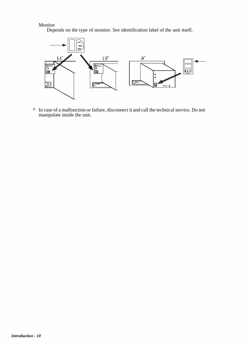
Central Unit (Power Supply Module)Must be 2 fast fuses (F) of 3.15 Amp./ 250V.
Introduction - 10
MonitorDepends on the type of monitor. See identification label of the unit itself.
* In case of a malfunction or failure, disconnect it and call the technical service. Do notmanipulate inside the unit.

Introduction - 11
FAGOR DOCUMENTATIONFOR THE 8050 CNC
8050 CNC OEM Manual Is directed to the machine builder or person in charge of installing and starting-up the CNC.
It is common to CNC models: 8050-M and 8050-T and it has the Installationmanual inside
8050-M CNC USER Manual Is directed to the end user or CNC operator.
It contains 2 manuals:Operating Manual describing how to operate the CNC.Programming Manual describing how to program the CNC.
8050-T CNC USER Manual Is directed to the end user or CNC operator.
It contains 2 manuals:Operating Manual describing how to operate the CNC.Programming Manual describing how to program the CNC.
8050 DNC Software Manual Is directed to people using the optional 8050 DNC communications software.
8050 DNC Protocol Manual Is directed to people wishing to design their own DNC communicationssoftware to communicate with the 8050.
AUTOCAD 8050 Manual Is directed to people wishing to design their own customized CNC screens andsymbols on AUTOCAD. This manual indicates how to set up the Autocadprogram for the CNC to correctly interpret the designed screens and symbols.
FLOPPY DISK Manual Is directed to people using the Fagor Floppy Disk Unit and it shows how to useit.

Introduction - 12
MANUAL CONTENTS
The Installation manual is common to CNC models: 8050-M and 8050-T and it is divided into the followingsections:
Index
New Features and modifications of the Mill Model
New Features and modifications of the Lathe Model
Introduction Warning sheet prior to start-upDeclaration of ConformitySummary of safety conditionsWarranty termsMaterial returningAdditional remarksFagor Documentation for the 8050 CNCManual Contents
Chapter 1 Configuration of the 8050 CNCIndicates the 8050 CNC structurePossible modular compositions for the Central UnitThe dimensions of each module of the Central UnitThe dimensions of each available monitorThe dimensions of the operator panelThe dimensions of the Monitor/Keyboard enclosureDetailed description of the front panel of each moduleDescription of the monitors and operator panelsDetailed description of all the connectors
Chapter 2 Machine and Power connectionIndicates how to connected to AC powerThe ground connectionThe characteristics of the analog inputs and outputsThe characteristics of the digital inputs and outputsThe CNC set-up and start-upEmergency input / output connection
Chapter 3 Machine parametersHow to operate with machine parametersHow to set the machine parametersDetailed description of all machine parametersAuxiliary M function table and their meaningLeadscrew error compensation parameter tableCross compensation parameters
Chapter 4 ConceptsAxes: nomenclature, selection, Gantry, slaved and synchronized axesFeedback systems, resolutionAxes adjustment, gain settingLeadscrew error compensationReference systems: reference points, search and settingSoftware axis travel limitsUnidirectional approachAuxiliary M, S, T function transferSpindle: speed control, range changeSpindle in closed loop, gain and reference point settingEmergency signal treatment at the CNC and at the PLC
Chapter 5 Introduction to the PLCAvailable resourcesPLC program executionModular structure of the programPriority of execution of the PLC modules
Chapter 6 PLC ResourcesInputs, Outputs, Marks, Registers, Timers and CountersAvailable resources and how they work

PageChapter: 1 Section:1CONFIGURATION OF THE FAGOR 8050 CNC
1. CONFIGURATION OF THE FAGOR 8050 CNC
The CNC is prepared to be used in Industrial Environments, especially on millingmachines, lathes, etc.
It can control machine movements and devices.
1.1 STRUCTURE OF THE 8050 CNC.
The FAGOR 8050 CNC is composed by the following modules:
- CENTRAL UNIT- MONITOR/KEYBOARD- OPERATOR PANEL
The OPERATOR PANEL module is connected to the MONITOR/KEYBOARD moduleby means of the provided cable. These two modules are placed next to each other and willbe connected to the CENTRAL UNIT module by means of the provided two cables. Thismodule may be installed at a different location away from the other two modules but nofarther than 25m (82ft.). These cables are:
- Video signal cable- Keyboard signal cable
CENTRALUNIT
MONITORKEYBOARD
OPERATORPANEL

Section:Chapter: 12
PageCONFIGURATION OF THE FAGOR 8050 CNC
1.2 CENTRAL UNIT
The CENTRAL UNIT is located in the electrical cabinet, it has a modular structure and itsbasic configuration is as follows:
- POWER SUPPLY MODULE- CPU MODULE- AXES MODULE- FAN MODULE
This configuration may be expanded by adding 1, 2 or 3 units of another module called:
- INPUT/OUTPUT MODULE- INPUT/OUTPUT AND TRACING MODULE (I/O TRACING)
When shorter CNC block processing and sampling times are required, optional CPU-PLCand CPU-TURBO boards should be used.
These boards may be inserted into the "AXES" module, into the "I/O" module or into the"I/O AND TRACING" module. One board per module.
These boards free the main CPU of the CNC from the following tasks:
* The CPU-PLC board manages the PLC program.* The CPU-TURBO manages the positioning loop of the axes, their interpolation, the
LOOK-AHEAD function, etc.
The modules forming the CENTRAL UNIT are installed on a RACK PANEL and theyare attached to it by two screws on the back of each module.
The data exchange between the various modules is carried out via the connection bus onthe RACK PANEL. Each module will be connected to this bus when its mounting screwsare fastened.
There are two types of RACK PANELS depending on the desired configuration: oneconceived for up to 5 modules (FAN MODULE included) and the other one for up to 7modules (FAN MODULE included).
All dimensions are in millimeters.
CENTRAL UNIT

PageChapter: 1 Section:3CONFIGURATION OF THE FAGOR 8050 CNC
The POWER SUPPLY module must be installed as first module from the left side and theCPU MODULE must go next to it (to its right). The rest of the modules (AXES, I/O andI/O TRACING) do not require a specific order and may be interchanged at will.
The FAN MODULE must be installed underneath the other ones and attached to theRACK by two nuts. The FAN MODULE provided will be different depending on the typeof configuration ordered.
Each module has a logic address (device select code), regardless of the physical positionit occupies, that identifies it to the CNC itself.
The factory-set logic address for each module is as follows:
Module Logic address (device select code)
AXES 2I/O 1 3I/O 2 4I/O 3 5I/O TRACING 6
The following options also have their own logic address (device select code):
CPU-PLC 1CPU-TURBO 7
However, it is possible to change the assignment of these addresses.
POWER CPU I/O AXES POWER AXES
FAN FAN
CPU I/O I/O I/O
CENTRAL UNIT

Section:Chapter: 14
PageCONFIGURATION OF THE FAGOR 8050 CNC CENTRAL UNIT
LogicAddress
Switch position1 2 3 4
0 OFF OFF OFF OFF1 OFF OFF OFF ON2 OFF OFF ON OFF3 OFF OFF ON ON4 OFF ON OFF OFF5 OFF ON OFF ON6 OFF ON ON OFF7 OFF ON ON ON8 ON OFF OFF OFF9 ON OFF OFF ON
10 ON OFF ON OFF11 ON OFF ON ON12 ON ON OFF OFF13 ON ON OFF ON14 ON ON ON OFF15 ON ON ON ON
To do this, remove the module cover located to its right and access the microswitcheslocated at one of the corners of the PC board.
The logic address (device select code) is defined in binary and can be selected between 1and 14. Addresses 0 and 15 are reserved.
When having several I/O modules, I/O(1) will be the one with the lowest address,I/O(2) will be the next one up and I/O(3) will have the highest address of all three.

PageChapter: 1 Section:5CONFIGURATION OF THE FAGOR 8050 CNC
235 +0,5 316 +0,5 219,5
347,5 347,5 347,5+0,5
+00,4
DIMENSIONS ANDINSTALLATION
1.2.1 DIMENSIONS AND INSTALLATION
The CENTRAL UNIT is attached to the electrical cabinet by means of the two screw holesprovided for that purpose. Make sure that the FAN module is installed underneath it.
All dimensions are in millimeters.

Section:Chapter: 16
PageCONFIGURATION OF THE FAGOR 8050 CNC
1.2.2 POWER SUPPLY MODULE
This module converts the A.C. power voltage into the different D.C. voltages required bythe other modules.
The CNC central unit must be powered by a separate shielded transformer of 110 VA withan output between 100V AC and 240V AC + 10% -15%.
In case of a power surge (outside of the 100V to 240V range), the power supply will shutoff, it is recommended to wait for about 3 minutes before powering the CNC up again.
For further information, please refer to the appendix corresponding to the technicalspecifications of the FAGOR 8050 CNC.
Atention:
Do not manipulate inside this unitOnly personnel authorized by Fagor Automation may manipulate insidethis module.
1.2.2.1 ELEMENT DESCRIPTION
1.- Lithium battery. Maintains the RAMdata when the system’s power disappears.
2.- Main AC fuses (2). It has two 3.15Amp./250V fast fuses (F), one per line toprotect the Main AC input.
3.- A.C. power connector. To power thecentral unit. It must be connected to thetransformer and to ground.
POWER SUPPLYMODULE
5
4
3
2
1
-5 VDC+15 VDC
-15 VDC +5 VDC
6
POWER

PageChapter: 1 Section:7CONFIGURATION OF THE FAGOR 8050 CNC
4.- Ground terminal. It must be connected to general machine groundpoint. Metric 6 mm.
5.- LEDs.. When on, they indicate that the various supply voltagesrequired by other modules are O.K.
6.- Heat-sink.
Atention:
Do not manipulate the connectors with the unit connected to main AC powerBefore manipulating these connectors, make sure that the unit is notconnected to main AC power.

Section:Chapter: 18
PageCONFIGURATION OF THE FAGOR 8050 CNC
1.2.3 CPU MODULE
This module performs all the functions of the CNC (edit, execute, display, etc) as well asprocessing the information from the rest of the modules and generating video signals for themonitor.
The EPROMS containing the system’s software are located in a removable cartridge inorder to ease future replacements. Note: Optional CPU PLC will contain its own EPROMs
Also the interconnection connectors for the CENTRAL UNIT and the MONITOR/KEYBOARD are located in this module.
Atention:
When replacing the CPU module, the CNC must be powered back onIMMEDIATELY in order to prevent the lithium battery from excessivedrainage.
Do not manipulate inside this unitOnly personnel authorized by Fagor Automation may manipulate insidethis module.
CPU MODULE

PageChapter: 1 Section:9CONFIGURATION OF THE FAGOR 8050 CNC
1.2.3.1 ELEMENT DESCRIPTION
X1 SUB-D type 25-pin female connectorto connect the CENTRAL UNIT with theKEYBOARD.
X2 SUB-D type 25-pin male connector toconnect the CENTRAL UNIT with theMONITOR.
X3 SUB-D type 9-pin female connectorto connect the SERIAL PORT RS 232 C.
X4 SUB-D type 9-pin male connector toconnect the SERIAL PORT RS 422.
1.- EPROM Cartridge. Is removable andcontains the system’s software.
2.- knurled screws. To fasten the EPROMcartridge to the module.
Atention:
Do not manipulate the connectors with the unit connected to main AC powerBefore manipulating these connectors, make sure that the unit is notconnected to main AC power.
1
2
2
CPUX1
X2X3
X4

Section:Chapter: 110
PageCONFIGURATION OF THE FAGOR 8050 CNC CPU MODULE
1.2.3.2 CONNECTORS AND CONNECTIONS
Connector X1
SUB-D type 25-pin female connector to connect the CENTRAL UNIT with theKEYBOARD.
FAGOR AUTOMATION provides the cable necessary for this connection. Thiscable has two 25-pin male connectors of the SUB-D type.
Both connectors have a latching system by means of two screws UNC4.40.
PIN CABLE COLOR SIGNAL
12345
greengreen-brown
bluewhiteblack
GNDC9
C11C13C15
6789
10
brown-redred
pink-browngray-brown
red-blue
C1C3C5C7D1
1112131415
brown-blueyellow-whiteyellow-brownwhite-blackwhite-green
D3D5D7C8
C10
1617181920
white-redwhite-graywhite-bluewhite-pink
pink
C12C14C0C2C4
2122232425
Metal housing
grayblownyellow
gray-pinkpurpleShield
C6D0D2D4D6
Chassis

PageChapter: 1 Section:11CONFIGURATION OF THE FAGOR 8050 CNC
The cable has 25 wires of 0.14 mm² (25 x 0.14mm²) section, global shielding and itis covered by acrylic rubber. The maximum length permitted is 25m (82ft).
The cable shield is soldered to the metallic housing of the connectors. This shield isconnected to pin 1 at both the CENTRAL UNIT and KEYBOARD connectors,
Outside shield solderedto metallic housing
Metallic housing
Shield
Heat shrink
CPU MODULE

Section:Chapter: 112
PageCONFIGURATION OF THE FAGOR 8050 CNC
Connector X2
25-pin male connector of the SUB-D type to connect the CENTRAL UNIT with theMONITOR.
FAGOR AUTOMATION provides the cable necessary for this connection. Thiscable has two 25-pin female connectors of the SUB-D type.
Both connectors have a latching system by means of two screws UNC4.40.
CPU MODULE
PAIR CABLE COLOR PIN SIGNAL
ShieldMetal
housingCHASSIS
1blue
white4
17VD4VD4
2red
yellow5
18VD3VD3
3greenpink
720
HSINCHSINC
4orange
white-black8
21VSINCVSINC
5redgray
922
VD0VD0
6greenwhite
1023
VD1VD1
7bluegray
1124
VD2VD2
8blackbrown
1225
BLANKBLANK

PageChapter: 1 Section:13CONFIGURATION OF THE FAGOR 8050 CNC
The cable has 8 twisted-pair wires of 0.34 mm² (8 x 2 x 0.34mm²) section with globalshielding and it is covered with acrylic rubber. It has a specific impedance of 120 ohmsand the maximum permitted length is 25m (82ft).
The cable shield is soldered to the metallic housing of the connectors. This shield isconnected to pin 1 at both the CENTRAL UNIT and MONITOR connectors,
Outside shield solderedto metallic housing
Metallic housing
Shield
Heat shrink
CPU MODULE

Section:Chapter: 114
PageCONFIGURATION OF THE FAGOR 8050 CNC
Connector X3
9-pin female connector of the SUB-D type to connect the RS 232 C serial port.
The cable shield must be soldered to pin 1 at the CNC end and to the metallic housingat the peripheral end.
CPU MODULE
PIN SIGNAL FUNCTION
123456789
FGTxDRxDRTSCTSDSRGND
DTR
ShieldTransmit DataReceive DataRequest To SendClear To SendData Send ReadyGround
Data Terminal Ready

PageChapter: 1 Section:15CONFIGURATION OF THE FAGOR 8050 CNC
SUGGESTIONS FOR THE RS 232C INTERFACE
* Connect/disconnect peripheral
The CNC must be powered off when connecting or disconnectingany peripheral through connector X3 (connector for the RS232Cinterface).
* Cable length
EIA RS232C standards specify that the capacitance of the cable must not exceed2500pF; therefore, since average cables have a capacitance between 130pF and170pF per meter, the maximum length of the cable should not be greater than 15m(49ft).
Shielded cables with twisted-pair wires should be used to avoid communicationinterference when using long cables.
Use shielded 7 conductor cable of 7 0.14 mm² section.
* Transmission speed (baudrate)
The most common baudrate used with peripherals is 9600 baud; but the CNC canoperate at up to 19200 baud.
All unused wires should be grounded to avoid erroneous control and data signals.
* Ground connection
It is suggested to reference all control and data signals to the same ground cable (pin7 GND) thus, avoiding reference points at different voltages especially in long cables.
CPU MODULE
*

Section:Chapter: 116
PageCONFIGURATION OF THE FAGOR 8050 CNC CPU MODULE
RECOMMENDED CONNECTIONS FOR THE RS 232 C INTERFACE
* Recommended connection for FAGOR floppy disc unit.
* Simplified connection
To be used when the peripheral or the computer meets one of the followingrequirements:
Does not have the RTS signalIt is connected via DNCThe receiver can receive data at the selected baudrate
Nevertheless, it is suggested to refer to the technical manuals of the peripheralequipment if there is any discrepancy.
CNC
HOUSING
PC/AT COMPUTER(connector X3)
FG 1TxD 2RxD 3CTS 5DSR 6DTR 9GND 7
1 FG2 RxD3 TxD8 CTS6 DSR4 DTR5 GND
1 FG2 TxD3 RxD5 CTS6 DSR20 DTR7 GND
FG 1TxD 2RxD 3CTS 5DSR 6DTR 9GND 7
9 pins
CNC COMPUTER PC/XT/PS2(connector X3)
HOUSING
25 pins
CNC (connector X3)
FG 1TxD 2RxD 3RTS 4CTS 5DSR 6DTR 9GND 7
FAGOR FLOPPY UNIT
1 FG3 TxD2 RxD7 RTS8 CTS6 DSR4 DTR5 GND

PageChapter: 1 Section:17CONFIGURATION OF THE FAGOR 8050 CNC
RS232C Connections
CPU MODULE

Section:Chapter: 118
PageCONFIGURATION OF THE FAGOR 8050 CNC CPU MODULE
PIN SIGNAL FUNCTION
123456789
FG
TxDRxDRxD
GNDTxD
Shield
Transmit dataReceive dataReceive data
Ground signalTransmit data
Connector X4
9-pin male connector of the SUB-D type to connect the RS 232 C serial port.
The cable shield must be soldered to pin 1 at the CNC end and to the metallic housingat the peripheral end.
CONSIDERATIONS REGARDING THE RS422 INTERFACE
It uses two separate wires for the signals. This offers the following advantages:
- It increases noise immunity.- The data transmission distance, at the same baudrate, is greater.- The problems due to signal interference and different voltage references are
minimized.
The RS422 standard defines the electrical interface to be used and it can be used inconjunction with the RS449 standard.
A terminating resistor must be installed between pins 3 and 8 (data transmit) andbetween pins 4 and 5 (Receive Data). These resistors must be installed on bothconnectors. Their values must match the cable´s impedance.
Typical value: 120 Ohm 1/4W
* Transmission speed (baudrate)
The common baudrate between the CNC and a peripheral device or computer is 9600Baud. However the CNC can operate at up to 19200 Baud.
It is recommended to ground the unused pins in order to avoid erroneous control anddata signal interpretations.

PageChapter: 1 Section:19CONFIGURATION OF THE FAGOR 8050 CNC CPU MODULE
RS 449CNC
HOUSING
3
FG
GND RxD
5
8
4
7
TxD
1
TxD
RxD
(connector X4)
TxDGND
TxDRxD
RxD
RECOMMENDED CABLE FOR THE RS422
RECOMMENDED CONNECTIONS
* Connect/disconnect peripheral
The CNC must be powered off when connecting or disconnecting any peripheralthrough connector X4 (RS422).
* Connection with serial port RS449
It is suggested to refer to the technical manual of the peripheral or computer to properlyidentify the signals and their corresponding pins.
TECHNICAL CHARACTERISTICS
BUÑOFLES COMPUTER PAR 3x2x0.34 mm2Individual shield + Overall shield (polyester/aluminum)
SPECIFICATIONS
Conductor Type: 7x0.25 mm (twisted-pair)Material: Tin-plated copperResistance: 52 Ohms/Km (32 Ohms/mile)
Insulation Material: Solid polyethylene
Shields Shields: Polyester/aluminum bandStranded tin-plated copper wire 7x0.25 mm
Outside cover Material: metal gray PVC
Capacitance Between conductors: 91,7 pF/m at 1 KHzBetween a conductor and the rest connected to shield:180 pF/m at 1 KHz
Impedance 50 Ohms

Section:Chapter: 120
PageCONFIGURATION OF THE FAGOR 8050 CNC
* Connection with an RS422 interface board from METRABYTE
HOUSING
PERIPHERAL
CPU MODULE
CNC (connector X4)
GND
TxD RxD
RxD
TxD
3
5
8
4
7
1 FG
GND RxD
TxD
TxD
RxD
* Connection with other peripherals
It is suggested to refer to the technical manual of the peripheral or computer to properlyidentify the signals and their corresponding pins.
RS 422
HOUSING
CNC
3
FG
GND RxD
5
8
4
7
1
TxD
RxD
8
9
4
5
1
2
7 3
6
(connector X4)
RxD
TxD RxD TxD
GND TxD
RTS
RTS CTS
CTS

PageChapter: 1 Section:21CONFIGURATION OF THE FAGOR 8050 CNC
CNC (connector X4)
FG 1TxD 3
TxD 8RxD 5
RxD 4GND 7
1 FG5 RxD
4 RxD3 TxD
8 TxD7 GND
FAGOR FLOPPY UNIT
CPU MODULE
* Connection for FAGOR floppy disc unit.

Section:Chapter: 122
PageCONFIGURATION OF THE FAGOR 8050 CNC
1.2.4 AXES MODULE
This module processes the control and feedback signals of up to 6 axes, plus spindle encoderand electronic handwheel.
This module also has a powerful PLC (Programmable Logic Controller) which, thanks toits own CPU, can execute in real time the logic program created by the user.
This module offers the following features to communicate with the outside world:
4 Feedback inputs admitting single-ended and double-ended (differential)squarewave signals as well as single-ended sinewave signals.
4 Feedback inputs admitting single and double-ended (differential) squarewavesignals.
8 Analog outputs for the servo drives.
24 Digital outputs ,optocoupled, commanded by the PLC.
40 Digital inputs ,optocoupled, read by the PLC.
8 Analog inputs to use at will on control and supervision systems.
1 Digital probe input.
Atention:
Do not manipulate inside this unitOnly personnel authorized by Fagor Automation may manipulate insidethis module.
AXES MODULE

PageChapter: 1 Section:23CONFIGURATION OF THE FAGOR 8050 CNC
1.2.4.1 ELEMENT DESCRIPTION.
X1, X2, X3 and X4. SUB-D type 15-pin femaleconnectors for feedback systems of each axis.The accept sinewave signals.
X5 and X6. SUB-D type 15-pin male connectorsfor feedback system of the axes. Up to 2 axesmay be connected per connector. They do notaccept sinewave signals.
X7. SUB-D type 15-pin male connector toconnect up to 8 analog inputs (range +5V) anda probe input (TTL or 24V).
X8. SUB-D type 15-pin female connector toconnect up to 8 analog outputs (range ±10V).
X9. SUB-D type 37-pin male connector for the32 PLC digital inputs.
X10. SUB-D type 37-pin female connector for the8 digital inputs of the PLC and its 24 digitaloutputs.
1.- 3,15Amp./250V. Fast fuse (F) for internalprotection of the PLC inputs and outputs.
Atention:
Do not manipulate the connectors with the unit connected to main AC powerBefore manipulating these connectors, make sure that the unit is notconnected to main AC power.
X1
X2X3
AXES
X5X4
X6X7
X8X9
X10
1
AXES MODULE

Section:Chapter: 124
PageCONFIGURATION OF THE FAGOR 8050 CNC AXES MODULE
1.2.4.2 CONNECTORS AND CONNECTIONS
Connectors X1, X2, X3, X4
They are 25-pin female connectors of the SUB-D type and they are used for thefeedback system connections of the axes.
It is required to set general machine parameters AXIS1, AXIS2, AXIS3 and AXIS4to indicate which axis has been connected to each one of them.
The cable must have global shielding. The rest of the specifications depend on thefeedback system utilized and the cable length required.
It is highly recommended to run these cables as far as possible from the power cablesof the machine.
The appendix at the end of this manual shows the characteristics of the square andsinusoidal feedback inputs and those of the differential feedback alarm signals.
When using a FAGOR 100P model handwheel, the axis selecting signal must beconnected to pin 5 of this connector.
PIN SIGNAL AND FUNCTION
1234
AABB
Differential squarewave feedbacksignals (double ended)
56
IoIo
Machine reference signals (Homemarker pulses)
78
AcBc
Depending on machine parameter,they could be sinewave feedback
signals or differential alarm signalsgenerated by certain transducers
91011121314
+5V+5V0V0V-5V-5V
Feedback system power supply
15 CHASSIS Shield

PageChapter: 1 Section:25CONFIGURATION OF THE FAGOR 8050 CNC
Connectors X5, X6
They are 15-pin male connectors of the SUB-D type utilized for feedback systemconnections.
It is possible to connect up to 2 axes to each one of them. It is required to set globalmachine parameters AXIS5, AXIS6, AXIS7 and AXIS8 to indicate which axes havebeen connected to each connector.
The cables must have global shielding. The rest of the specifications depend on thefeedback system utilized and the cable length required.
It is highly recommended to run these cables as far as possible from the power cablesof the machine.
When using a FAGOR 100P model handwheel, the axis selecting signal must beconnected to pin 5 of this connector.
The appendix at the end of this manual shows the characteristics of the square andsinusoidal feedback inputs and those of the differential feedback alarm signals.
PIN SIGNAL AND FUNCTION
1234
AABB
Differential squarewave feedbacksignals (double ended)
56
IoIo
Machine reference signals(Home marker pulses)
78
+5V0V
Feedback system power supply
9101112
AABB
Differential squarewave feedbacksignals (double ended)
1314
IoIo
Machine reference signals(Home marker pulses)
15 CHASSIS Shield
AXES MODULE

Section:Chapter: 126
PageCONFIGURATION OF THE FAGOR 8050 CNC
Connector X7
It is a 15-pin male connector of the SUB-D type utilized for touch probe input and forthe analog inputs.
It is possible to connect up to 8 analog inputs which could be used for systemsupervision, etc. Their analog value must be within + 5V.
There are two probe inputs (5V and 24V) and the 0V probe input must be connectedto the 0V of the external power supply.
Refer to the appendix at the end of this manual for more details on the characteristicsof these probe inputs and recommended interface connections.
All shields must only be connected to ground at the CNC end leaving the other endfree.The wires of the shielded cables cannot be unshielded for more than 75mm (about3 inches).
The meaning or use of pin 11 of this connector has been changed for those modelscorresponding to version 09A and newer (See serial number on the module's topcover). The previous models used this pin as 0V input for the analog signals. But fromthis version 09A on, it is used as the +5V output to feed the probe.
For models prior to version 09A
PIN SIGNAL AND FUNCTION
123456789
1011
I01I02I03I04I05I06I07I080V0V0V
Analog inputs, range ±5V
121314
PROBE 5PROBE 24PROBE 0
Probe input 5V TTLProbe input 24V Vcc
Probe input 0V
15 CHASSIS Shield
AXES MODULE

PageChapter: 1 Section:27CONFIGURATION OF THE FAGOR 8050 CNC
PIN SIGNAL AND FUNCTION
123456789
10
I01I02I03I04I05I06I07I080V0V
Analog inputs, range ±5V
11121314
+5VPROBE 5
PROBE 24PROBE 0
+5V output to feed the probeProbe input 5V TTLProbe input 24V Vcc
Probe input 0V
15 CHASSIS Shield
AXES MODULE
For models with version 09A and newer
Atention:
When using pin 11 as +5V power supply output for the probe, pin 14 (PROBE0) must be connected to either pin 9 or 10 (0V) of this connector.
The machine manufacturer must comply with the EN 60204-1 (IEC-204-1)regulation regarding the protection against electrical shock derived fromdefective input/output connection with the external power supply when thisconnector is not connected before turning the power supply on.

Section:Chapter: 128
PageCONFIGURATION OF THE FAGOR 8050 CNC
Connector X8
It is a 15-pin female connector of the SUB-D type used for the analog servo outputs
Each one of the outputs (O1 thru O8) correspond to the feedback inputs X1 thru X6.The name of the axis connected to each one of them is determined by setting globalmachine parameters AXIS1 thru AXIS8.
All shields must only be connected to ground at the CNC end leaving the other endfree.
The wires of the shielded cables cannot be unshielded for more than 75mm (about 3inches).
AXES MODULE
PIN SIGNAL AND FUNCTION
12345678
O01O02O03O04O05O06O07O08
Servo analog outputsRange ±10V
91011121314
GNDGNDGNDGNDGNDGND
Reference signal for theanalog outputs
15 CHASSIS Shield

PageChapter: 1 Section:29CONFIGURATION OF THE FAGOR 8050 CNC
Connector X9
It is a 37-pin male connector of the SUB-D type utilized for the PLC digital inputs.
Since the response time of the EMERGENCY signal must be very short, the FAGOR8050 CNC has assigned input I1 for this purpose. Thus, the CNC will treat this inputimmediately regardless of how the PLC program uses it.
The 0V of the power supply used for these inputs must be connected to pins 18 and19 of the connector.
AXES MODULE
PIN SIGNAL AND FUNCTION
123456789
10111213141516171819202122232425262728293031323334353637
I01I03I05I07I09I11I13I15I17I19I21I23I25I27I29I310V0V
I02I04I06I08I10I12I14I16I18I20I22I24I26I28I30I32
CHASSIS
EMERGENCY STOP
External power supply
Shield

Section:Chapter: 130
PageCONFIGURATION OF THE FAGOR 8050 CNC
Connector X10
It is a 37-pin female connector of the SUB-D type used for the inputs and outputs ofthe PLC.
When an error is issued, the CNC, besides indicating it to the PLC, activates outputO01 of this connector. This way, regardless of how this signal is treated by the PLCprogram, the electrical cabinet can process this signal immediately.
Both 24V and 0V of the power supply used to power these I/Os must be connectedto pins 18 and 19 (for 0V) and pins 1 and 20 (for the 24V).
AXES MODULE
PIN SIGNAL AND FUNCTION
123456789
10111213141516171819202122232425262728293031323334353637
24VO01O03O05O07O09O11O13O15O17O19O21O23I33I35I37I390V0V24VO02O04O06O08O10O12O14O16O18O20O22O24I34I36I38I40
CHASSIS
External power supplyEMERGENCY OUTPUT
External power supply
External power supply
Shield

PageChapter: 1 Section:31CONFIGURATION OF THE FAGOR 8050 CNC
Atention:
The Emergency output, which coincides with O1 of the PLC, will be activated(change from logic level 1 to 0) when an ALARM or ERROR occurs at theCNC or when the PLC output O1 is set to 0 (logic level 0).
The machine manufacturer must comply with the EN 60204-1 (IEC-204-1)regulation regarding the protection against electrical shock derived fromdefective input/output connection with the external power supply when thisconnector is not connected before turning the power supply on.

Section:Chapter: 132
PageCONFIGURATION OF THE FAGOR 8050 CNC
1.2.5 I/O MODULE
This module is used to expand the number of digital inputs and outputs of the basicconfiguration.
Each module provides:
64 Optocoupled digital inputs.32 Optocoupled digital outputs.
The maximum configuration possible with one axis module and three I/O modules is:
232 Digital inputs (40 + 3 64)120 Digital outputs (24 + 3 32)
The numbering of the various inputs and outputs of each module depends on the logicaddress assigned to the module and it is as follows:
AXES module I1 -I40O1 -O24I/O 1 module I65 -I128 O33-O64I/O 2 module I129-I192 O65-O96I/O 3 module I193-I256 O97-O128
The PLC can control up to 256 inputs and 256 outputs although it can only communicateto the outside world through the ones indicated above.
Atention:
Do not manipulate inside this unitOnly personnel authorized by Fagor Automation may manipulate insidethis module.
**
I / O MODULE

PageChapter: 1 Section:33CONFIGURATION OF THE FAGOR 8050 CNC
1.2.5.1 ELEMENT DESCRIPTION
X1 and X2. 37-pin male connector of theSUB-D type for 64 digital inputs of theINTEGRATED PLC.
X3 37-pin female connector of the SUB-D typefor 32 digital outputs of the INTEGRATEDPLC.
1.- 3.15Amp./250V Fast fuse (F) for internalcircuitry protection of the INTEGRATEDPLC (PLCI) inputs and outputs.
Atention:
Do not manipulate the connectors with the unit connected to main AC powerBefore manipulating these connectors, make sure that the unit is notconnected to main AC power.
I/OX1
X3
X2
1

Section:Chapter: 134
PageCONFIGURATION OF THE FAGOR 8050 CNC
1.2.5.2 CONNECTORS AND CONNECTIONS
Connectors X1, X2
37-pin male connectors of the SUB-D type used for the PLC inputs.
The 0V of the external power supply used for the PLC inputs must be connected topins 18 and 19 (0V) of each connector.
Connector X1 Connector X2
I / O MODULE
PIN SIGNAL AND FUNCTION
123456789
10111213141516171819202122232425262728293031323334353637
I97I99I101I103I105I107I109I111I113I115I117I119I121I123I125I1270V0V
I98I100I102I104I106I108I110I112I114I116I118I120I122I124I126I128
CHASSIS
External powersupply
Shield
PIN SIGNAL AND FUNCTION
123456789
10111213141516171819202122232425262728293031323334353637
I65I67I69I71I73I75I77I79I81I83I85I87I89I91I93I950V0V
I66I68I70I72I74I76I78I80I82I84I86I88I90I92I94I96
CHASSIS
External powersupply
Shield

PageChapter: 1 Section:35CONFIGURATION OF THE FAGOR 8050 CNC I / O MODULE
Connector X3
37-pin female connector of the SUB-D type used for the PLC outputs.
Both the 24V and the 0V of the external power supply used for these outputs must beconnected to pins 18 and 19 (for 0V) and 1 and 20 (for 24V).
Atention:
Te machine manufacturer must comply with the EN 60204-1 (IEC-204-1)regulation regarding the protection against electrical shock derived fromdefective input/output connection with the external power supply when thisconnector is not connected before turning the power supply on.
PIN SIGNAL AND FUNCTION
123456789
10111213141516171819202122232425262728293031323334353637
24VO33O35O37O39O41O43O45O47O49O51O53O55O57O59O61O630V0V24VO34O36O38O40O42O44O46O48O50O52O54O56O58O60O62O64
CHASSIS
External power supply
External power supply
External power supply
Shield

Section:Chapter: 136
PageCONFIGURATION OF THE FAGOR 8050 CNC
1.2.6 FAN MODULE
This module, whose purpose is to maintain the equipment at the proper operatingtemperature, may have one or two fans depending on the selected configuration.
It must be powered by a 24V (+15% -25%) D.C. power supply separate from the rest ofthe equipment.
Atention:
Do not maipulate inside this unitOnly personnel authorized by Fagor Automation may manipulate insidethis module.
1.2.6.1 ELEMENT DESCRIPTION
X1 Power supply connector
1.- 3,15Amp./250V fast fuse (F) to protect the fan.
2.- 3,15Amp./250V fast fuse (F) to protect the other fan.
1.2.6.2 CONNECTORS
Connector X1
3-pin male connector of the WEIDMÜLLER type used for the PLC power supply.
FAN MODULE
1 2
X1

PageChapter: 1 Section:37CONFIGURATION OF THE FAGOR 8050 CNC I/O AND TRACING MODULE
MODULELOGIC
ADDRESSI/Os
AXESI/O TRACING
I/O (1)I/O (2)
2345
I1-I40 O1-O24I65-I128 O33-O64I129-I192 O65-O96I193-I256 O97-O128
I65-I96
1.2.7 I/O AND TRACING MODULE
This module is used to expand the number of digital inputs and outputs of the basicconfiguration and it allows the possibility to use the Renishaw SP2 probe, for tracing parts.
The internal adaptor that this module has for the Renishaw SP2 probe multiplies the signalsreceived by a factor of 2, thus obtaining a resolution of 1 micron (40 millionths of an inch).
This module also provides:
32 Optocoupled digital inputs.32 Optocoupled digital outputs.
The maximum configuration possible with one AXES module, the I/O AND TRACINGmodule and two I/O modules is:
200 Digital inputs (40 + 32 + 2 x 64)120 Digital outputs (24 + 32 + 2 x 32)
The numbering of the various inputs and outputs of each module depends on the logicaddress assigned to the module in such way that the first group of I/Os corresponds to thelowest address and the last one to the highest address. for example:
The PLC can control up to 256 inputs and 256 outputs although it can only communicateto the outside world through the ones indicated above.
Atention:
Do not manipulate inside this unitOnly personnel authorized by Fagor Automation may manipulate insidethis module.

Section:Chapter: 138
PageCONFIGURATION OF THE FAGOR 8050 CNC
I/OX1
X3
X2
1
I/O AND TRACING MODULE
1.2.7.1 ELEMENT DESCRIPTION
X1 . 25-pin female connector of the SUB-D type to connect the Renishaw SP2probe.
X2. 37-pin male connector of the SUB-Dtype for 32 digital inputs of theINTEGRATED PLC.
X3 37-pin female connector of the SUB-D type for 32 digital outputs of theINTEGRATED PLC.
1.- 3.15Amp./250V Fast fuse for internalcircuitry protection of the INTEGRATEDPLC (PLCI) inputs and outputs.
Atention:
Do not manipulate the connectors with the unit connected to main AC powerBefore manipulating these connectors, make sure that the unit is notconnected to main AC power.

PageChapter: 1 Section:39CONFIGURATION OF THE FAGOR 8050 CNC I/O AND TRACING MODULE
CNC PIN COLOR SIGNAL FUNCTIONRENISHAW
PIN
12345
Brown
Yellow
Xa--
Ya-
Sin XReservedReserved
Sin YReserved
N
G
6789
10
Green
Pink
-Za--
OVER 1
ReservedSin Z
ReservedReserved
Overtravel Alarm
M
K
1112131415
Pink/Grey
Purple
OVER 2--
Xb-
Overtravel AlarmReservedReserved
Cos XReserved
V
E
1617181920
Grey
White
Yb-
Zb--
Cos YReserved
Cos ZReservedReserved
C
H
2122232425
RedBlackBlue
Shield
-+15V
0V-15V
Chassis
ReservedPower SupplyPower SupplyPower Supply
Shield
UABR
1.2.7.2 CONNECTORS AND CONNECTIONS
Connector X1
25-pin female connector of the SUB-D type used to connect the Renishaw SP2 probe.
FAGOR AUTOMATION provides the union cable required for this connection. Itconsists of a cable hose, one SUB-D type 25-pin male connector and the correspondingconnector for the Renishaw SP2.
The male connector has a latching system by means of two UNC4.40 screws.
The cable used has 12 conductors of 0.14mm² section, global shield and it is coveredby acrylic rubber.

Section:Chapter: 140
PageCONFIGURATION OF THE FAGOR 8050 CNC
PIN SIGNAL AND FUNCTION
123456789
10111213141516171819202122232425262728293031323334353637
I65I67I69I71I73I75I77I79I81I83I85I87I89I91I93I950V0V
I66I68I70I72I74I76I78I80I82I84I86I88I90I92I94I96
CHASSIS
External powersupply
Shield
I/O AND TRACING MODULE
Connector X2
37-pin male connector of the SUB-D type used for the PLC inputs.
The 0V of the external power supply used for the PLC inputs must be connected topins 18 and 19 (0V) of each connector.

PageChapter: 1 Section:41CONFIGURATION OF THE FAGOR 8050 CNC
PIN SIGNAL AND FUNCTION
123456789
10111213141516171819202122232425262728293031323334353637
24VO33O35O37O39O41O43O45O47O49O51O53O55O57O59O61O630V0V24VO34O36O38O40O42O44O46O48O50O52O54O56O58O60O62O64
CHASSIS
External power supply
External power supply
External power supply
Shield
I / O TRACING MODULE
Connector X3
37-pin female connector of the SUB-D type used for the PLC outputs.
Both the 24V and the 0V of the external power supply used for these outputs must beconnected to pins 18 and 19 (for 0V) and 1 and 20 (for 24V).

Section:Chapter: 142
PageCONFIGURATION OF THE FAGOR 8050 CNC
1.3 MONITOR / KEYBOARD
This module, installable on the pendant, allows the operator to access all the informationprovided by the MONITOR as well as operate the CNC by means of the keyboard and theoperator panel.
This module contains the connectors for the interconnections between the CENTRALUNIT and the MONITOR/KEYBOARD unit.
Atention:
Do not manipulate inside this unitOnly personnel authorized by Fagor Automation may manipulate insidethis module.
Do not manipulate the connectors with the unit connected to main AC powerBefore manipulating these connectors, make sure that the unit is notconnected to main AC power.
MONITOR / KEYBOARD

PageChapter: 1 Section:43CONFIGURATION OF THE FAGOR 8050 CNC
1.3.1 ELEMENT DESCRIPTION
X1 25-pin female connector of the SUB-D type to connect the keyboard signals.
X2 25-pin male connector of the SUB-D type to connect the video signals.
X3 15-Pin female connector of the SUB-D type to connect the KEYBOARD withthe OPERATOR PANEL.
1.- A.C. power connector: Use the connector provided for this purpose connectingit to 220V A.C. and ground.
2.- Ground terminal: To connect the general machine ground connections. Metricscrew 6mm.
3.- Buzzer

Section:Chapter: 144
PageCONFIGURATION OF THE FAGOR 8050 CNC
9 " monitor
X1 SUB-D type 25-in female connector to connect the KEYBOARD and theCENTRAL UNIT.
X2 SUB-D type 25-in male connector to connect the MONITOR and theCENTRAL UNIT.
1.- Ground terminal: Used for the general ground connection. Metric 6mm.
2.- A.C. power fuses (2). One for each line.
3.- On/off power switch.
4.- A.C. power connector: for A.C. power and ground connection.
5.- MONITOR contrast adjusting knob.
6.- MONITOR brightness adjusting knob.
7.- Buzzer.
MONITOR / KEYBOARD

PageChapter: 1 Section:45CONFIGURATION OF THE FAGOR 8050 CNC
1.3.2 CONNECTORS AND CONNECTIONS
Connectors X1, X2
They are described in the section for the CPU module of the CENTRAL UNIT.
Connector X3 on 14" monitors
15-pin male connector of the SUB-D type used to connect the KEYBOARD with theOPERATOR PANEL.
FAGOR AUTOMATION provides the 15-conductor ribbon-cable required for thisconnection. It is 250mm long (about 10 inches).
When a greater separation between the Monitor/keyboard and the Operator panel isdesired, this cable must be replaced with a 15-conductor cable of 15 0.14mm2
section, global shielding and covered with acrylic rubber. The maximum total lengthof the cable connecting the Central Unit and the Keyboard must not exceed the 25m(82ft).
1 9
8 15
1 9
8 15
KEYBOARD side OPERATOR PANEL side
PIN SIGNAL
12345
uC13uC12jC11jC10
6789
10
JC9D7D6D5D4
1112131415
D3D2D1D0
D14
MONITOR / KEYBOARD

Section:Chapter: 146
PageCONFIGURATION OF THE FAGOR 8050 CNC
1.3.3 DIMENSIONS OF THE MONITOR/KEYBOARD (mm)(14" monitor)
MONITOR / KEYBOARD

PageChapter: 1 Section:47CONFIGURATION OF THE FAGOR 8050 CNC
(9" and 10" monitors)
MONITOR / KEYBOARD

Section:Chapter: 148
PageCONFIGURATION OF THE FAGOR 8050 CNC
1.3.4 MONITOR/KEYBOARD ENCLOSURES (mm)
MONITOR / KEYBOARD

PageChapter: 1 Section:49CONFIGURATION OF THE FAGOR 8050 CNC
The minimum distance from each side of the monitor to its enclosure in order to guarantee therequired ambient conditions is shown below:
Monitor A B C D E
9", 10" 100 mm 100 mm 100 mm 100 mm 150 mm
14" 100 mm 100 mm 100 mm 150 mm 50 mm
A fan must be used to improve ventilation inside the enclosure. This fan must be D.C. poweredsince A.C. powered fans generate magnetic fields which could distord the image on the CRT.
MONITOR / KEYBOARD

Section:Chapter: 150
PageCONFIGURATION OF THE FAGOR 8050 CNC
X1
1 2REAR VIEW
X2
1.4 OPERATOR PANEL
This module, which is connected to the MONITOR/KEYBOARD by a ribbon cable,contains the keys to Jog the axes of the machine (Feedrate Override Knob, normal speedand fast jog keys), Cycle Start and Cycle Stop keys as well as either an Emergency Stopbutton or an electronic Handwheel (optional).
1.4.1 ELEMENT DESCRIPTION
X1 15-pin female connector of the SUB-D type to connect the OPERATORPANEL with the MONITOR/KEYBOARD
X2 Not used.
2.- Optional connection for the E-STOP button or the electronic Handwheel
1.4.2 CONNECTORS AND CONNECTIONS
Connector X1
It is described in the section for the MONITOR/KEYBOARD.
OPERATOR PANEL

PageChapter: 1 Section:51CONFIGURATION OF THE FAGOR 8050 CNC
93
9,5 74,5
93
74,5 9,5
9,5
456 475
== = =
23
6
412 70
80
27,5
180 width x 70 height
1.4.3 DIMENSIONS OF THE OPERATOR PANEL (mm)
Mill Model Lathe Model
OPERATOR PANEL

PageChapter: 2 Section:1POWER AND MACHINE CONNECTION POWER CONNECTION
2. POWER AND MACHINE CONNECTION
Atention:
Power switchThis power switch must be mounted in such a way that it is easilyaccessed and at a distance between 0.7 meters (27.5 inches) and 1.7meters (5.5ft) off the floor.
Install this unit in the proper placeIt is recommended to install the CNC away from coolants, chemicalproducts, possible blows etc. which could damage it.
2.1 POWER CONNECTION
The CENTRAL UNIT of the FAGOR 8050 CNC has a three-prong connector located inthe POWER SUPPLY MODULE to be connected to A.C. power and ground.
This connection must be done through an independent shielded 110VA transformer withan A.C. output voltage between 100V and 240V +10% -15%.
The FAN MODULE, located in the central unit, must be powered with a 24V D.C. powersupply independent of the rest of the equipment.
The MONITOR/KEYBOARD must be powered with 220V A.C.

Section:Chapter: 22
Page
POWER AND MACHINE CONNECTION MACHINE CONNECTION
2.2 MACHINE CONNECTION
2.2.1 GENERAL CONSIDERATIONS
The machine tool must have decoupled all those elements capable of generating interference(relay coils, contactors, motors, etc.)
* D.C. relay coils.
Diode type 1N4000.
* A.C. relay coils.
RC connected as close as possible to the coils. Their approximate values should be:
R 220 Ohms/1WC 0,2 µF/600V
* A.C. motors.
RC connected between phases with values:
R 300 Ohms/6WC 0,47µF/600V

PageChapter: 2 Section:3POWER AND MACHINE CONNECTION MACHINE CONNECTION
Ground connection.
It is imperative to carry out a proper ground connection in order to achieve:
* Protection of anybody against electrical shocks caused by a malfunction.
* Protection of the electronic equipment against interference generated by the propermachine or by other electronic equipment near by which could cause erraticequipment behavior.
Therefore, it is crucial to install one or two ground points where the above mentionedelements must be connected.
Use large section cables for this purpose in order to obtain low impedance and efficientlyavoid any interference. This way all parts of the installation will have the same voltagereference.
Even when a proper ground connection reduces the effects of electrical interference(noise), the signal cables require additional protection.This is generally achieved by using twisted-pair cables which are also covered with anti-static shielding mesh-wire. This shield must be connected to a specific point avoidingground loops that could cause undesired effects. This connection is usually done at oneof CNC’s ground point.
Each element of the machine-tool/CNC interface must be connected to ground via theestablished main points. These points will be conveniently set close to the machine-tool andproperly connected to the general ground (of the building).
When a second point is necessary, it is recommended to join both points with a cable whosesection is no smaller than 8 mm².
Verify that the impedance between the central point of each connector housing and the mainground point is less than 1 Ohm.

Section:Chapter: 24
Page
POWER AND MACHINE CONNECTION MACHINE CONNECTION
Ground connection diagram
Chassis
Ground
Ground (for safety)

PageChapter: 2 Section:5POWER AND MACHINE CONNECTION
2.2.2 DIGITAL OUTPUTS.
The 8050 CNC system offers a number of optocoupled digital outputs which can be usedto activate relays, deacons, etc.
These digital outputs, corresponding to the PLC, are located at the AXES MODULE andat the I/O MODULE. Each of these modules provides:
* 24 outputs on the AXES module (connector X10).* 32 outputs on each of the I/O modules (connector X3).
All these outputs, with galvanic protection by optocouplers, can commutate D.C. voltagessupplied by the electrical cabinet of the machine.
The electrical characteristics of these outputs are:
Nominal voltage value +24 V D.C.Maximum voltage value +30 V.Minimum voltage value +18 V.Output voltage 2V less than power supply voltage Vcc.Maximum output current 100 mA.
All outputs are protected by means of:
Galvanic isolation by optocouplersExternal 3A fuse for:protection against external power supply surges (over 33VCC) andprotection against reversal connection of the power supply.
DIGITAL OUTPUTS

Section:Chapter: 26
Page
POWER AND MACHINE CONNECTION
2.2.3 DIGITAL INPUTS.
The digital inputs offered by the 8050 CNC system are used to read external devices, etc.
These digital inputs, corresponding to the PLC, are located on the AXES module and onthe I/O module. Each one of them contains:
* 40 inputs on the AXES module (connectors X9, X10).* 64 inputs on each of the I/O modules (connectors X1, X2).
All of them offer galvanic isolation, between the CNC circuitry and the outside world, byoptocouplers .
The electrical characteristics of these inputs are:
Nominal voltage value +24V D.C.Maximum voltage value +30V.Minimum voltage value +18V.High threshold voltage (logic level 1) +18V.Low threshold voltage (logic level 0) +5V.Typical consumption for each input 5 mA.Maximum consumption for each input 7 mA.
All inputs are protected by means of:
Galvanic isolation by optocouplers.Protection against reversal of power supply connection up to -30 V.
Atention:
The external 24V power supply. used for the PLC’s inputs and outputs MUSTbe regulated.
The 0V point of this power supply must be connected to the main ground pointof the electrical cabinet.
DIGITAL INPUTS

PageChapter: 2 Section:7POWER AND MACHINE CONNECTION
2.2.4 ANALOG OUTPUTS.
The 8050 CNC system offers 8 analog outputs which could be used to command servodrives, spindle drives and other devices.
These analog outputs are located on the AXES module (connector X8).
The electrical characteristics of these outputs are:
Analog voltage range: ............................................ +10VMinimum impedance of the connected drive: ........ 10KWMaximum cable length without shield: .................. 75 mm (3 inches)
It is highly recommended to use shielded cable connecting the shield to the correspondingpin of the X8 connector at the AXES module.
Atention:
It is recommended to adjust the servo drives so the maximum feedrate (G00)is obtained at +9.5V.
2.2.5 ANALOG INPUTS.
The 8050 CNC offers 8 analog inputs used for supervision, control, etc. of external devices.
These analog inputs are located in the AXES module (connector X7).
The electrical characteristics of these inputs are:
Analog voltage range: ............................+5VInput impedance: ....................................20KWMaximum cable length without shield: ...75mm (3 inches)
It is highly recommended to use shielded cable connecting the shield to the correspondingpin of the X7 connector at the AXES module.
ANALOG INPUTS ANDOUTPUTS

Section:Chapter: 28
Page
POWER AND MACHINE CONNECTION START UP
2.3 START UP
2.3.1 GENERAL CONSIDERATIONS
Inspect the whole electrical cabinet verifying the ground connections BEFORE poweringit.
This ground connection must be done at a single machine point (Main Ground Point) andall other ground points must be connected to this point.
Verify that the 24V power supply used for the digital inputs and outputs of the PLC isREGULATED and that its 0V are connected to the Main Ground Point.
Verify the connection of the feedback system cables to the CNC.
DO NOT connect or disconnect these cables to/from the CNC when the CNC is on.
Look for shortcircuits in all connectors (inputs, outputs, axes, feedback, etc.) BEFOREsupplying power to them.
2.3.2 PRECAUTIONS
It is recommended to reduce the axis travel installing the limit switches closer to each otheror detaching the motor from the axis until they are under control.
Verify that there is no power going from the servo drives to the motors.
Verify that the connectors for the digital inputs and outputs are disconnected.
Verify that the E-STOP button is pressed.

PageChapter: 2 Section:9POWER AND MACHINE CONNECTION
2.3.3 CONNECTION
Verify that the A.C. power is correct.
With the CNC completely disconnected from the electrical cabinet, power the electricalcabinet and verify that it responds properly:
Verify that there is proper voltage between the pins corresponding to 0V and 24V ofthe connectors for the digital inputs and outputs.
Apply 24V to each one of the terminals of the electrical cabinet being used thatcorrespond to the digital outputs of the CNC and verify their correct performance.
With the motors being decoupled from the axes, verify that the system consisting ofdrive, motor and tach is operating properly.
Connect the A.C. power to the CNC. If there is any problem, the CNC will display thecorresponding error. Install the machine parameters and PLC program.
With power turned off, connect the I/O and feedback connectors to the CNC.
Connect the CNC and the electrical cabinet to A.C. power and confirm the countingdirection of each axis. Select the PLC monitoring mode at the CNC and activate the digitaloutputs (O1=1) one by one to verify their proper operation. Enable the servos and confirmtheir proper closed-loop operation.
2.3.4 MACHINE PARAMETER SETTING
The machine parameters relate the CNC to the particular machine. The values that the CNCassigns to each one of them by default are described in the chapter dedicated to MachineParameters.
These values, shown in the Parameter Tables, may be modified manually from the CNC’skeyboard or from a peripheral (cassette reader, floppy disk reader, computer, etc.) via thetwo serial communication ports RS 232C and RS 422.
Once the new parameter values are entered, key in SHIFT and then RESET or turn theCNC off and back on so these new values are assumed by the CNC.
START UP

Section:Chapter: 210
Page
POWER AND MACHINE CONNECTION
2.3.5 ADJUSTMENT OF THE MACHINE PARAMETERS FOR THE AXES
Once the active axes have been assigned by means of general machine parameters“AXIS1” thru “AXIS8”, the CNC will enable the relevant axes parameter tables.
The values to be assigned to the parameters of each of these tables will depend on the resultsobtained when adjusting each machine axis.
Before starting the adjustment of the axes, it is a good idea to move them close to the middleof their travels placing the travel-limit switches (controlled by the electrical cabinet) closeto these points in order to avoid any damage to the machine.
Verify that the PLC Mark “LATCHM” is OFF. Then, after selecting the parameters of thedesired axes, go on to adjusting them following these advises:
* Adjust the axes one by one.
* Connect the power output of the drive corresponding to the axis being adjusted.
* Move the axis being adjusted in the JOG mode.
In case of run-away, the CNC will display the relevant following error and themachine parameter labelled LOOPCHG (corresponding to the sign of the analogoutput of the CNC) will have to be changed.
* If the axis does not run away; but the direction of the move is not the desired one,parameters labelled AXISCHG (axis feedback counting direction) and LOOPCHG(sign of the analog output) will have to be changed.
START UP

PageChapter: 2 Section:11POWER AND MACHINE CONNECTION
2.3.6 MACHINE REFERENCE POINT ADJUSTMENT FOR EACHAXIS (HOME)
Once the movement of the axes has been properly adjusted, place the travel-limit switchesback where they should be.
The following adjusting sequence is one of the many that could be used:
* This adjustment should be done one axis at a time.
* Indicate in the Axis Machine Parameter for the axis REFPULSE the type of markerpulse Io being used for Home Search.
* Set Axis Machine Parameter REFDIREC to indicate the direction of the axis whensearching Home.
* Set General Machine Parameters REFEED1 and REFEED2 to indicate the feedratesfor Home search.
* Set Axis Machine Parameter REFVALUE to 0.
* Once the JOG mode has been selected at the CNC, position the axis so the Homesearch can be carried out in the desired direction and execute the home search fromthis JOG mode. When the search is completed, the CNC will assign a 0 position valueto this point (Machine Reference Point).
* If the Machine Reference Zero desired is in a different physical location from theMachine Reference Point (location of the marker pulse), proceed as follows:
move the axis to a known position and the value displayed by the CNC will be thevalue to be assigned to Axis Machine Parameter REFVALUE.
Machine coordinate of the measured point - CNC reading at that point.
Example:
After homing and moving the axis to a known point, if this known point is 3inches away from the desired Machine Zero and the CNC shows it to be -1.7inches away from the Machine Reference Point (marker pulse location); thedistance from the Reference Point to the Reference Zero will be:
“REFVALUE” = 3 - (-1.7) = 4.7 inches.
Assign this new value to REFVALUE and press SHIFT RESET or turn the CNCoff and back on so it assumes this new value.
If REFVALUE is other than 0, it is necessary to search Home once again in order forthis axis to assume the correct reference values.
START UP

Section:Chapter: 212
Page
POWER AND MACHINE CONNECTION
2.3.7 SOFTWARE TRAVEL LIMITS FOR THE AXES (soft limits)
Once Home Search has been carried out on all the axes, the soft limits for the CNC haveto be established.
This is achieved a single axis at a time and in the following manner:
* Jog the axis in the positive direction to a point close to the travel limit switch keepinga safety distance from it.
* Assign the position value displayed by the CNC to Axis Machine Parameter“LIMIT+”.
* Repeat those steps in the negative direction assigning the displayed value to AxisMachine Parameter “LIMIT-”.
* Once this process is completed, hit SHIFT RESET or turn the CNC off and back onin order for it to assume the new values.
2.3.8 ADJUSTMENT OF THE DRIFT (OFFSET) AND MAXIMUMFEEDRATE (G00)
These adjustments are performed on servo drives of the axes and on spindle drives.
Drift adjustment (offset)
* Disconnect the analog input and short-circuit it with a wire jumper.
* Turn the offset potentiometer of the drive until the voltage on the tach terminals is 0mVD.C.
* Take the wire jumper out.
START UP

PageChapter: 2 Section:13POWER AND MACHINE CONNECTION
Adjustment of the maximum feedrate
It is recommended to adjust the drives so the maximum feedrate is obtained with ananalog signal of 9.5V. If they are adjusted to a different voltage, it must be indicated inthe Axis Machine Parameter or the Spindle parameter “MAXVOLT”.
Also, the maximum feedrate must be indicated in the Axis Machine Parameter“G00FEED”.
The maximum feedrate can be calculated from the motor rpms, the gear ratios and thetype of leadscrew being used.
Example:
A motor can turn at 3000 rpms and it is attached to a 5 pitch screw (5 turns/inch).
The maximum feedrate will be:
3000 rev./min. x 1 inch./5 rev. = 600 inch/min
This will be the value to be assigned to Axis Machine Parameter “G00FEED”.
Once these values are assigned to the relevant parameters, the drives must be adjusted.
To do so, a CNC program can be executed which will move the axis back and forthcontinuously at G00 feedrate. This program could be:
N10 G00 G90 X200X-200(GOTO N10)
If the Tach in use provides 20V per 1000 rpms, its voltage should be:
20 V. x 3000 rpm = 60 V.
1000 rpm
START UP

Section:Chapter: 214
Page
POWER AND MACHINE CONNECTION
2.3.9 CONNECTION OF THE EMERGENCY INPUT AND OUTPUT
The EMERGENCY INPUT of the CNC, pin 2 of connector X9 of the AXES module,corresponds with the I01 input of the PLC and must be supplied with 24V.
Since the CNC also processes this signal directly, if the 24V disappears, the CNC willdisplay EMERGENCY ERROR and will deactivate all axes enables and will cancel allanalog outputs.
During the initializing process carried out by the CNC on power-up, the EMERGENCYOUTPUT of the CNC (pin 2 of connector X10) remains at logic level 0 in order to avoida premature activation of the electrical cabinet.
If this process is successful, the CNC will release control of the EMERGENCY OUTPUTto the PLC. Otherwise, it will keep it active (low) and it will display the corresponding errormessage.
Once this process is over, the PLC will execute the PLC program stored in memory if anyor, if none is available, it will “wait” for one to be entered and executed.
After completing the execution of the initial cycle (CY1) of the PLC program or, in itsabsence, the first cycle it will assign the value of the PLC output O1 to the physicalEMERGENCY output.
It is recommended to program the CY1 cycle of the PLC program assigning a value of 1to O1 when everything checks out fine and a value of 0 when there is an error.
The interface of the electrical cabinet will take into account all the elements that could causethis type of error. Among such elements are:
* E-stop has been pressed.
* Travel limit switch of any axis has be pressed.
* There is a malfunction on a drive or it is locked without analog signal.
START UP
EmergencySTOP
8050 CNC
ELECTRICAL CABINET

PageChapter: 2 Section:15POWER AND MACHINE CONNECTION
When the CNC detects an error, it will activate the CNC to PLC signal “/ALARM", andit will activate the Emergency output (logic level 0) at pin 2 of connector X10 of the AXESmodule.
Since this signal corresponds to the PLC output O1, it can also be activated by the PLCprogram.
The recommended connection diagram can be one of the following:
European Style:
USA Style:
START UP
ElectricalCabinetEmergency
RE
24V DC
0 V
EmergencyStop Relay
0 VO 01
I 01
RSEX10(2)
Emergency stopX9(2)
Emergency output
RSE
RE
E-STOPbutton
Otheremergencycontacts
8050 CNC
EmergencySTOP
ELECTRICAL CABINET

Section:
1MACHINE PARAMETERSPageChapter: 3
3. MACHINE PARAMETERS
Atention:
It is highly recommended to save the machine parameters in a peripheral deviceor computer in order to avoid losing them by replacing modules, checksumerrors, operator errors, etc.
3.1 INTRODUCTION
On power-up, the CNC performs a system autotest and when this is over, it displays thefollowing screen:
The CNC allows the display of a previously defined screen instead of the FAGOR logo.This screen will be defined using the GRAPHIC EDITOR (refer to the operating manualof the 8050 CNC).
If any error occurs, it will be displayed in the message window.
11:50:14
F1 F2 F4 F5 F6 F7F3
CAP INSMessagewindow
Monday 07 September 1992 11:50 :14
SIMULATEEXECUTE JOG TABLES +EDIT UTILITIES

Chapter: 3Page Section:
2 MACHINE PARAMETERS
The main menu for the various operating modes will appear at the bottom of the CRT.These options will be selected using the softkeys F1 thru F7.
Since it is possible to have more than 7 options to choose from at one time, use the “+”softkey to display the rest of them.
Once the MACHINE PARAMETERS operating mode has been selected, the CNC offersaccess to the following tables:
General Machine ParametersMachine Parameters for the Axes (one table per axis)Spindle ParametersParameters for serial ports (RS-422 and RS-232-C)PLC parametersMiscellaneous Functions MLeadscrew Error Compensation (one table per axis)Cross compensation
On all of them, it is possible to move the cursor line by line using the arrow keys or pageby page using the Pagedown and Pageup keys.

Section:
3MACHINE PARAMETERSPageChapter: 3
3.2 OPERATION WITH PARAMETER TABLES
Once one of the table lines has been selected, the user can move the cursor over this lineby means of the right and left arrow keys .
It is also possible to perform other functions by using the following keys:
* CL erases characters.
* INS switches between insert and replace writing modes.
* CAP switches between upper case and lower case letters; when the CRT showsCAP, it will indicate that the upper case mode has been selected.
Make sure this mode is selected since all characters entered in these tables must beupper case.
* The ESC key cancels the editing of the line.
* When pressing ENTER the edited parameter goes into the table.
The CNC offers the following options when working with each parameter of these tables:
* EDIT a parameter. The CNC will indicate the proper format by means of thesoftkeys.
* MODIFY a parameter. Position the cursor over the desired parameter to be modifiedand press this softkey.
Make the changes using the keys described above.
And press ENTER. The new parameter value will appear in its previous location inthe table.
* FIND a parameter. The cursor will be positioned over the indicated parameter. Withthis function it is also possible to “find” the beginning or the end of the table.
* INITIALIZE the table assuming the default values.
* LOAD the table receiving its values via any of the two serial ports of the CNC: RS-232-C or RS-422.
* SAVE the table values out to a peripheral device via any of the two serial ports of theCNC: RS-232-C or RS-422.
* Display the parameter values in millimeters or inches by pressing the MM/INCHkey. Only those parameters affected by this conversion will be altered. The generalmachine parameter “INCHES” will not be changed.

Chapter: 3Page Section:
4 MACHINE PARAMETERS
3.3 MACHINE PARAMETER SETTING
In order for the machine-tool to be able to properly execute the programmed instructionsas well as interpret the different elements connected to it, the CNC must “know” thespecific data of the machine, such as: feedrates, accelerations, feedback, automatic toolchange, etc..
This data is determined by the machine builder and can be introduced either from theCNC’s keyboard or via the CNC’s two serial ports.
The FAGOR 8050 CNC offers the following machine parameter groups:
* General Parameters.
* Axes Parameters.
* Spindle Parameters.
* Parameters for the two communication channels, RS-422 and RS-232-C.
* PLC Parameters.
* M Miscellaneous Functions (Auxiliary functions).
* Leadscrew error compensation.
* Cross Compensation.
First, the general machine parameters must be set since they determine the machine axes.
There are some parameters to indicate whether the machine has cross compensation or not.These compensation tables will be generated by the CNC from the values assigned to thoseparameters.
The general machine parameters also determine the number of elements at the tables fortools, tool magazine, tool offsets and M functions (miscellaneous).
The axes parameters will define the Leadscrew Compensation Tables and they will onlybe generated for those axes which require them.

Section:
5MACHINE PARAMETERSPageChapter: 3
3.3.1 GENERAL MACHINE PARAMETERS
AXIS1 (P0)
Indicates the axis whose feedback is connected to connector X1 and whose analogsignal comes out of output O01 of connector X8 of the AXES module. The possiblevalues are:
0 = Free. Not associated with any axis.1 = X axis2 = Y axis3 = Z axis4 = U axis5 = V axis6 = W axis7 = A axis8 = B axis9 = C axis10 = Main spindle11 = Handwheel12 = Handwheel with axis selector button13 = Auxiliary spindle / Live tool14 = Second main spindle (only on Lathe models)
By default, this parameter is set to 1 (X axis).
AXIS2 (P1)
Indicates the axis whose feedback is connected to connector X2 and whose analogsignal comes out of output O02 of connector X8 of the AXES module.
By default, the CNC assigns a value of 2 (Y axis) if Mill model and a value of 3 (Zaxis) if Lathe model.
AXIS3 (P2)
Indicates the axis whose feedback is connected to connector X3 and whose analogsignal comes out of output O03 of connector X8 of the AXES module.
By default, the CNC assigns a value of 3 (Z axis) if Mill model and a value of 10(spindle) if Lathe model.
AXIS4 (P3)
Indicates the axis whose feedback is connected to connector X4 and whose analogsignal comes out of output O04 of connector X8 of the AXES module.
By default, the CNC assigns a value of 4 (U axis) if Mill model and a value of 11(handwhell) if Lathe model.
GENERAL

Chapter: 3Page Section:
6 MACHINE PARAMETERS
AXIS5 (P4)
Indicates the axis whose feedback is connected to connector X5 (pins 1 thru 6) andwhose analog signal comes out of output O05 of connector X8 of the AXES module.It uses the same definition code as AXIS1.
By default, the CNC assigns a value of 5 (V axis) if Mill model and a value of 0 (free)if Lathe model.
AXIS6 (P5)
Indicates the axis whose feedback is connected to connector X5 (pins 9 thru 14) andwhose analog signal comes out of output O06 of connector X8 of the AXES module.It uses the same definition code as AXIS1.
By default, the CNC assigns a value of 10 (Spindle) if Mill model and a value of 0 (free)if Lathe model.
AXIS7 (P6)
Indicates the axis whose feedback is connected to connector X6 (pins 1 thru 6) andwhose analog signal comes out of output O07 of connector X8 of the AXES module.It uses the same definition code as AXIS1.
By default, the CNC assigns a value of 11 (Handwheel) if Mill model and a value of0 (free) if Lathe model.
AXIS8 (P7)
Indicates the axis whose feedback is connected to connector X6 (pins 9 thru 14) andwhose analog signal comes out of output O08 of connector X8 of the AXES module.It uses the same definition code as AXIS1.
By default, the CNC assigns a value of 0 (Free).
INCHES (P8)
It defines the measuring units assumed by the CNC for machine parameters, tool tablesand programming on power-up and after executing M02,M30, EMERGENCY orRESET. The code is:
0 = millimeters (G71)1 = inches (G70)
By default, the CNC assigns a value of 0 (mm) to this parameter.
GENERAL

Section:
7MACHINE PARAMETERSPageChapter: 3
IMOVE (P9) (Initial MOVEment)
Indicates which function G00 (rapid traverse) or G01 (linear interpolation) is assumedon power-up, after executing M02,M30, EMERGENCY or RESET. The code is:
0 = G00 (rapid traverse)1 = G01 (linear interpolation)
By default the CNC assigns a value of 0 (G00) to this parameter.
ICORNER (P10) (Initial CORNER)
Indicates which function: G05 (round corner) or G07 (square corner) is assumed onpower-up, after executing M02,M30, EMERGENCY or RESET. The code is:
0 = G07 (square corner)1 = G05 (round corner)
By default, the CNC assigns a value of 0 (G07) to this parameter.
IPLANE (P11) (Initial PLANE)
Indicates which function: G17 (XY plane) or G18 (ZX plane) is assumed on power-up, after executing M02,M30, EMERGENCY or RESET. The code is:
0 = G17 (XY plane)1 = G18 (ZX plane)
By default, the CNC assigns a value of 0 (G17) to this parameter if Mill model and avalue of 1 (G18) if Lathe model.
ILCOMP (P12) (Initial Length COMPensation)
It is only used in the Mill model CNC and indicates which function: G43 (tool lengthcompensation ON) or G44 (tool length compensation OFF) is assumed on power-up,after executing M02,M30, EMERGENCY or RESET. The code is:
0 = G44 (tool length compensation OFF)1 = G43 (tool length compensation ON)
By default, the CNC assigns a value of 0 (G44) to this parameter.
GENERAL

Chapter: 3Page Section:
8 MACHINE PARAMETERS
ISYSTEM (P13) (Initial SYSTEM)
Indicates which function: G90 (absolute programming) or G91 (incrementalprogramming) is assumed on power-up, after executing M02,M30, EMERGENCYor RESET. The code is:
0 = G90 (absolute programming)1 = G91 (incremental programming)
By default, the CNC assigns a value of 0 (G90) to this parameter.
IFEED (P14) (Initial FEED)
Indicates which function: G94 (feedrate in mm/min or inch/min) or G95 (mm/rev or inch/rev) is assumed on power-up, after executing M02,M30, EMERGENCYor RESET. The code is:
0 = G94 (mm/min or inch/min)1 = G95 (mm/rev or inch/rev)
By default, the CNC assigns a value of 0 (G94) to this parameter.
THEODPLY (P15) (THEOretical DisPLaY)
Indicates whether the CNC will display real or theoretical position values accordingto the following code:
0 = real position values1 = theoretical position values
By default, the CNC will assume a value of 1 (theoretical display).
GRAPHICS (P16)
On MILL MODEL 8050 CNCs, this parameter indicates the axis system being usedfor the graphic representation as well as the motion possibilities for the W axis addedto those of the Z axis in the graphic representation.
Possible values: 0 = Mill graphics1 = Mill graphics with added W axis2 = Boring Mill graphics3 = Boring Mill graphics with added W axis
On LATHE MODEL 8050 CNCs, this parameter indicates the axes coordinatessystem to be used for the graphic representation.
GRAPHICS=0 GRAPHICS=1GRAPHICS=2 GRAPHICS=3
X
XXX
ZZZ
Z
GENERAL

Section:
9MACHINE PARAMETERSPageChapter: 3
RAPIDOVR (P17) (RAPID OVeRride)
Indicates whether it is possible to vary the feedrate override between 0% and 100%when working in G00.
The feedrate can be overridden from the Feedrate Override Knob on the operatorpanel, from the PLC, via DNC or by program.
YES = It is possible to vary the % of G00 (rapid).NO = It is NOT possible to vary it, remaining set at 100%.
By default, the CNC assumes YES for this parameter (Feedrate override active).
MAXFOVR (P18) (MAXimum Feed OVeRride)
Indicates the maximum value of the FEEDRATE OVERRIDE applicable to theprogrammed feedrate.
The programmable feedrate F can be varied between 0% and 120% from the overrideknob on the operator panel or between 0% and 255% from the PLC, via DNC or byprogram.
The resulting feedrate will be limited to the value indicated in the axis machineparameter “MAXFEED”.
Possible values: Integers between 0 and 255
By default, the CNC assumes a value of 120 for this parameter.
CIRINLIM (P19) (CIRcular INterpolation LIMit)
Indicates the maximum angular feedrate value for circular interpolations.
This limitation prevents circular interpolations resulting in polygons instead of arcswhen the radius is very small. The CNC adjusts the angular feedrate in order not toexceed the selected maximum angular feedrate.
Example:
If “CIRINLIN” = 1500 and an arc of a radius = 0.5mm at F=10000mm/min. Theresult is:
Theoretical angular feedrate = 10000 mm/min : 0.5 mm.= 20000 min.-1
But, since the speed was limited to 1500, the CNC adjusts the feedrate in thefollowing manner:
Feedrate to be applied = 1500 x 0.5 = 750 mm/min.
Possible values: between 0 and 65535. A value of 0 means that no feedrate limitationis to be applied.
By default, the CNC assumes a value of 0 for this parameter (not limited).
GENERAL

Chapter: 3Page Section:
10 MACHINE PARAMETERS
CIRINERR (P20) (CIRcular INterpolation ERRor)
Indicates the maximum error allowed when calculating the end point of an arc.
From the programmed path, the CNC will calculate the radius for both the startingpoint and end point of the arc. Although both of them should be “exactly” the same,This parameter allows a certain calculation tolerance by establishing the maximumdifference between these two radii.
Possible values: 0.0001 thru 99999.9999 millimeters0.00001 thru 3937.00787 inches.
By default, the CNC assumes a value of 0.01 mm for this parameter.
PORGMOVE (P21) (Polar ORiGin MOVEment)
Indicates whether the CNC assumes or not as the new polar coordinate origin thecenter of the last G02 or G03 programmed.
YES = it does.NO = The polar origin is not affected by G02 or G03.
By default, the CNC assumes NO for this parameter.
BLOCKDLY (P22) (BLOCK DeLaY)
Indicates the dwell in milliseconds (0 thru 65535) between blocks when executingmoves in G07 (square corner).
This dwell can be very useful when some devices have to activated after the executionof each block.
By default, the CNC assumes a value of 0 (no dwell) for this parameter.
NTOOL (P23) (Number of TOOLs)
Indicates the number of tools in the tool magazine.
Possible values: Integers between 0 and 255.
By default, the CNC assumes a value of 100 for this parameter.
NPOCKET (P24) (Number of POCKETs)
Indicates the number of pockets in the tool magazine.
Possible values: integers 0 thru 255.
By default, the CNC assumes a value of 100 for this parameter if Mill model and avalue of 0 if Lathe model.
GENERAL

Section:
11MACHINE PARAMETERSPageChapter: 3
RANDOMTC (P25) (RANDOM Tool Changer)
Indicates whether the tool magazine is RANDOM or not.
On a RANDOM magazine, the tool may occupy any position (pocket).On a NON-RANDOM magazine, the tool always occupies its own pocket.
YES = It is a RANDOM tool magazine.NO = It is Not a RANDOM tool magazine.
By default, the CNC assumes that it is NOT random.
If this machine parameter is set for RANDOM magazine, machine parameter"TOFFM06" (P28) must be set for machining center.
TOOLMONI (P26) (TOOL MONItor)
Selects the display units of the tool’s nominal and real lives.
0 = Minutes.1 = Number of operations.
By default, the CNC assumes a value of 0 (minutes) to this parameter.
NTOFFSET (P27) (Number of Tool OFFSETs)
Indicates the number of tool offsets available in the tool offset table.
Possible values: Integers 0 thru 255.
By default, the CNC assumes a value of 100 for this parameter.
TOFFM06 (P28) (Tool OFFset with M06)
Indicates whether the machine is a machining center or not.
If it is, the CNC will select, at the tool magazine, the tool indicated when executingthe "T" function and it will be necessary to execute M06 afterwards in order to carryout the tool change.
YES = It is a machining center.NO = It is not a machining center.
By default, the CNC assumes that it is NOT a machining center.
It is recommended to associate he subroutine corresponding to the tool changer withthe M06.
Note: Parameters 23 through 28 as well as 60 and 61 relate to the tool changer.
GENERAL

Chapter: 3Page Section:
12 MACHINE PARAMETERS
NMISCFUN (P29) (Number of MISCellaneous FUNctions)
Indicates the number of M functions available in the M function table.
Possible values: Integers 0 thru 255.
By default, the CNC assumes a value of 32 for this parameter.
MINAENDW (P30) (MINimum Aux END Width)
Indicates the minimum time period that the AUX END signal must remain activatedso the CNC will interpret it as a valid signal.
AUX END is a PLC signal which indicates to the CNC that functions M,S or T havebeen executed.
If the corresponding M function has been set in the M table not to wait for the AUXEND signal, the time period indicated in this parameter will be the duration of theMSTROBE signal.
Possible values: Integers 0 thru 65535 milliseconds.
By default, the CNC will assume a value of 100 for this parameter.
The application of this parameter is described in the section: “TRANSFERRINGAUXILIARY M,S,T FUNCTIONS” of the chapter: “CONCEPT SUBJECT”.
NPCROSS (P31) (Number of Points CROSS compensation)
Indicates the number of points available in the first cross compensation table.
This compensation is used when the movement of one axis causes a position changeon another axis. The CNC offers a table where one could enter the position variationsof one axis for the particular positions of the other axis.
Possible values: Integers 0 thru 255.
By default, the CNC assumes a value 0 for this parameter (no cross compensationbeing applied).
MOVAXIS (P32) (MOVing AXIS)
Used in the first cross compensation table, it indicates the axis causing positionvariations on another axis. The definition code is :
0 = None. 5 = V axis1 = X axis 6 = W axis2 = Y axis 7 = A axis3 = Z axis 8 = B axis4 = U axis 9 = C axis
By default the CNC assumes a 0 value for this parameter (none).
GENERAL

Section:
13MACHINE PARAMETERSPageChapter: 3
COMPAXIS (P33) (COMPensated AXIS)
Used in the first cross compensation table, it indicates the axis suffering the positionvariations caused by another axis. The compensation is applied onto this axis. Thedefinition code is:
0 = None.1 = X axis2 = Y axis3 = Z axis4 = U axis5 = V axis6 = W axis7 = A axis8 = B axis9 = C axis
By default, the CNC assumes a value of 0 for this parameter (none).
Example:
If NPCROSS=20, MOVAXIS=X and COMPAXIS=W, the CNC will allowaccess to the cross compensation table.
Each one of these 20 points (NPCROSS) of this table will indicate the X positionvalue and the error suffered by the W axis when the X axis is positioned at thispoint.
This way, the CNC will apply this compensation onto the W axis.
Note: Parameters P54 through P59 are associated with the 2nd and 3rd crosscompensation tables.
REFPSUB (P34) (REFerence Point SUBroutine)
Indicates the number of the subroutine associated with function G74 (machinereference zero or home search). This subroutine will be executed automatically whenG74 is programmed alone in a block or, also, when searching home in the JOG modeby pressing the softkey “ALL AXES”.
Possible values: integers 0 thru 9999. 0 means that there is no associated subroutineto be executed.
By default, the CNC assumes a value of 0 for this parameter.
GENERAL

Chapter: 3Page Section:
14 MACHINE PARAMETERS
INT1SUB (P35) (INT1 SUBroutine)INT2SUB (P36) (INT2 SUBroutine)INT3SUB (P37) (INT3 SUBroutine)INT4SUB (P38) (INT4 SUBroutine)
They indicate the number of the subroutine associated with the corresponding generallogic input: "INT1" (M5024), "INT2" (M5025), "INT3" (M5026)", "INT4" (M5027).
When one of these inputs is activated, the program currently being executed isinterrupted and the CNC jumps to execute the associated subroutine whose numberis indicated in the corresponding parameter.
These interruption subroutines do not change the nesting level of local parameters,thus only global parameters must be used in them.
Once the CNC completes the execution of the subroutine, it will continue running theoriginal program.
Possible values: Integers between 0 and 9999. If set to "0", no subroutine will beexecuted.
By default, these parameters are set to "0" (no subroutine is associated).
PRBPULSE (P39) (PRoBe PULSE)
Indicates whether the probe functions of the CNC react to the up-flank (leading edge)or down-flank (trailing edge) of the probe signal. This probe is connected to theconnector X7 of the AXES module.
Sign + = leading edge (24V. or 5V positive pulse.)Sign - = trailing edge (0V negative pulse.)
By default, the CNC assumes a + (positive pulse) value for this parameter
PRBXMIN (P40) (PRoBe X MINimum value)PRBXMAX (P41) (PRoBe X MAXimum value)PRBYMIN (P42) (PRoBe Y MINimum value)PRBYMAX (P43) (PRoBe Y MAXimum value)PRBZMIN (P44) (PRoBe Z MINimum value)PRBZMAX (P45) (PRoBe Z MAXimum value)
Indicate the position of the table-top probe used for tool calibration.
These position values must be absolute and with respect to machine reference zero(home). If a Lathe model, these values mut be in radius.
GENERAL

Section:
15MACHINE PARAMETERSPageChapter: 3
PRBXMIN indicates minimum X position value of the probe.PRBXMAX indicates maximum X position value of the probe.PRBYMIN indicates minimum Y position value of the probe.PRBYMAX indicates maximum Y position value of the probe.PRBZMIN indicates minimum Z position value of the probe.PRBZMAX indicates maximum Z position value of the probe.
Possible values: ±99999.9999 millimeters.±3937.00787 inches.
By default, the CNC assumes a value of 0 for this parameter.
PRBMOVE (P46) (PRoBe MOVEment)
Indicates the maximum distance the tool can travel when calibrating it with a probein JOG mode.
Possible values: Between 0.0001mm and 99999.9999mm.Between 0.00001 inch and 3937.00787 inches.
The default value for this parameter is 50 mm (about 2 inches).
USERDPLY (P47) (USER DisPLaY)
Indicates the number of the USER display program associated to the EXECUTEmode. This program will be executed via the user channel when pressing the softkeyUSER in the EXECUTE mode.
Possible values: integers 0 thru 65535. 0 means that there is no program associatedwith the USER channel for the EXECUTE mode.
By default, the CNC assumes a value of 0 to this parameter.
YZ
X
PRBZMAX
PRBZMIN
PRBXMIN PRBXMAX
Z
X
PRBYMAX
PRBYMIN
Y
X PRBXMIN PRBXMAX
GENERAL

Chapter: 3Page Section:
16 MACHINE PARAMETERS
USEREDIT (P48) (USER EDITor)
Indicates the number of USER display program associated to the EDIT mode. Thisprogram will be executed via the user channel when pressing the softkey USER in theEDIT mode.
Possible values: Integers 0 thru 65535. 0 means that there is no program associatedwith the USER channel in the EDIT mode.
By default, the CNC assumes a value of 0 for this parameter.
USERMAN (P49) (USER MANual)
Indicates the number of the USER display program associated to the JOG mode. Thisprogram will be executed via the user channel when pressing the softkey USER in theJOG mode.
Possible values: integers 0 thru 65535. 0 means that there is no program associatedwith the USER channel for the JOG mode.
By default, the CNC assumes a value of 0 to this parameter.
USERDIAG (P50) (USER DIAGnosis)
Indicates the number of the USER display program associated to the DIAGNOSISmode. This program will be executed via the user channel when pressing the softkeyUSER in the DIAGNOSIS mode.
Possible values: integers 0 thru 65535. 0 means that there is no program associatedwith the USER channel for the DIAGNOSIS mode.
By default, the CNC assumes a value of 0 to this parameter.
ROPARMIN (P51) (Read Only PARameter MINimum)ROPARMAX (P52) (Read Only PARameter MAXimum)
Indicate the upper limit “ROPORMAX” and the lower limit “ROPORMIN” of theglobal arithmetic parameter group (P100-P299) to be write protected.
Possible values: Integers 0 thru 9999.
If a value less than 100 is assigned to this parameter, the CNC will assumea value of 100.If a value greater than 299 is assigned to this parameter, the CNC willassume a value of 299.
By default, the CNC assumes a value of 0 for these parameters (none of the arithmeticparameters are protected).
GENERAL

Section:
17MACHINE PARAMETERSPageChapter: 3
GENERAL
PAGESMEM (P53) (PAGES MEMory)
Indicates the percentage (%) of EEPROM memory dedicated to store the customizedPages (screens) and Symbols created with the graphic editor.
This EEPROM memory stores the following information:
* The user pages and symbols as mentioned above.
* The PLC program. the percentage (%) of EEPROM memory used to store thisprogram is established by PLC machine parameter "PLCMEM".
* The part-programs of the CNC and the PLC errors in the remaining free memoryspace of the EEPROM.
Possible values: Integers between 0 and 100.
The default value for this parameter is 50.
Atention:
Changing this parameter can cause items previously stored in EEPROMmemory to be lost.
To avoid this, proceed as follows:
1.- Transfer the data from the EEPROM to a peripheral or PC.2.- Change the setting of "PAGESMEM" and "PLCMEM".3.- Press [SHIFT] [RESET].4.- Re-enter all the data back into the EEPROM.
NPCROSS2 (P54) (Number of Points CROSS compensation 2)
Indicates the number of points available in the second cross compensation table.
This compensation is used when the movement of one axis causes a position changeon another axis. The CNC offers a table where one could enter the position variationsof one axis for the particular positions of the other axis.
Possible values: Integers 0 thru 255.
By default, the CNC assumes a value 0 for this parameter (no cross compensationbeing applied).

Chapter: 3Page Section:
18 MACHINE PARAMETERS
MOVAXIS2 (P55) (MOVing AXIS 2)
Used in the second cross compensation table, it indicates the axis causing positionvariations on another axis. The definition code is :
0 = None. 5 = V axis1 = X axis 6 = W axis2 = Y axis 7 = A axis3 = Z axis 8 = B axis4 = U axis 9 = C axis
By default the CNC assumes a 0 value for this parameter (none).
COMAXIS2 (P56) (COMpensated AXIS 2)
Used in the second cross compensation table, it indicates the axis suffering the positionvariations caused by another axis. The compensation is applied onto this axis. Thedefinition code is:
0 = None. 5 = V axis1 = X axis 6 = W axis2 = Y axis 7 = A axis3 = Z axis 8 = B axis4 = U axis 9 = C axis
By default, the CNC assumes a value of 0 for this parameter (none).
Example:
If NPCROSS2=15, MOVAXIS2=2 and COMAXIS2=8, the CNC will allowaccess to the second cross compensation table.
Each one of these 15 points (NPCROSS2) of this table will indicate the Xposition value and the error suffered by the B axis when the Y axis is positionedat this point.
This way, the CNC will apply this compensation on to the B axis.
NPCROSS3 (P57) (Number of Points CROSS compensation 3)
Indicates the number of points available in the third cross compensation table.
This compensation is used when the movement of one axis causes a position changeon another axis. The CNC offers a third table where one could enter the positionvariations of one axis for the particular positions of the other axis.
Possible values: Integers 0 thru 255.
By default, the CNC assumes a value 0 for this parameter (no third cross compensationbeing applied).
GENERAL

Section:
19MACHINE PARAMETERSPageChapter: 3
MOVAXIS3 (P58) (MOVing AXIS 3)
Used in the third cross compensation table, it indicates the axis causing positionvariations on another axis. The definition code is :
0 = None. 5 = V axis1 = X axis 6 = W axis2 = Y axis 7 = A axis3 = Z axis 8 = B axis4 = U axis 9 = C axis
By default the CNC assumes a 0 value for this parameter (none).
COMAXIS3 (P59) (COMpensated AXIS 3)
Used in the third cross compensation table, it indicates the axis suffering the positionvariations caused by another axis. The compensation is applied onto this axis. Thedefinition code is:
0 = None. 5 = V axis1 = X axis 6 = W axis2 = Y axis 7 = A axis3 = Z axis 8 = B axis4 = U axis 9 = C axis
By default, the CNC assumes a value of 0 for this parameter (none).
Example:
If NPCROSS3=25, MOVAXIS3=3 and COMAXIS=4, the CNC will allowaccess to the third cross compensation table.
Each one of these 25 points (NPCROSS3) of this table will indicate the Xposition value and the error suffered by the U axis when the Z axis is positionedat this point.
This way, the CNC will apply this compensation onto the U axis.
GENERAL

Chapter: 3Page Section:
20 MACHINE PARAMETERS
TOOLSUB (P60) (TOOL SUBroutine)
Indicates the number of the subroutine associated with the tools. This subroutine willbe executed automatically every time a T function is executed.
Possible values: Integers between 0 and 9999. If a value of 0 is assigned to thisparameter, the CNC will assume that no subroutine is to be executed.
By default, this parameter is set to 0 (no associated subroutine).
When set with a value other than 0, the T function must be written alone in the blockor only with the desired tool offset D.
CYCATC (P61) (CYClic Automatic Tool Changer)
Indicates whether a cyclic tool changer is being used or not.
A "cyclic tool changer" is an automatic tool changer which requires an M06 command(tool change) after searching for a tool and before searching for the next one.
A non-cyclic tool changer can perform several tool searches in a row without havingto program an M06.
NO = The tool changer being used is not cyclic (no M06 required).YES = The tool changer being used is cyclic (requires M06).
By default, the CNC takes the "YES" value for this parameter (cyclic).
TRMULT (P62) (TRacing MULTiplier)
It is only used on Mill model CNCs and has no effect on CNC version 9.01 andlater.
Indicates the multiplier factor used for the tracing operation. It admits any integer valuebetween 0 and 9999 where the value of 1000 corresponds to a factor of 1.
It is recommended to set it with a value of 0 when the tracing axis uses the feed-forwardgain and no derivative gain is used.
When this parameter is set to a value other than 0, the derivative gain may be used forthe control loop of the tracing axis.
If the tracing axis is associated with another axis, like a gantry axis or slaved axis, thisparameter must be set to 0.
By default, the CNC sets this parameter to a value of 0.
GENERAL

Section:
21MACHINE PARAMETERSPageChapter: 3
TRPROG (P63) (TRacing PROportional Gain)
Indicates the value of the Proportional Gain used for tracing.It admits any integer value between 0 and 9999 where a value of 1000 correspondsto a factor of 1.
By default, the CNC sets this parameter to a value of 250.
TRDERG (P64) (TRacing DERivative Gain)
Indicates the value of the Derivative Gain used for tracing. It admits any integer valuebetween 0 and 9999 where a value of 1000 corresponds to a factor of 1.
By default, the CNC sets this parameter to a value of 250.
MAXDEFLE (P65) (MAXimum DEFLEction)
Indicates the maximum deflection allowed for the probe while tracing.
The CNC will correct the probe position everytime this parameter value is reached.
Possible values: between 0 and 99999.9999 mmbetween 0 and 3937.00787 inches
By default, the CNC sets this parameter to a value of 4mm.
The value assigned to this parameter must be less than or equal to the value that theprobe has for "Measuring range".
MINDEFLE (P66) (MINimum DEFLEction )
Indicates the minimum deflection used by the probe while tracing.
Possible values: between 0 and 99999.9999 mmbetween 0 and 3937.00787 inches
By default, the CNC sets this parameter to a value of 0.2 mm.
The value assigned to this parameter must be less than the value assigned to the generalmachine parameter "MAXDEFLE".
TRFBAKAL (P67) (TRace FeedBAcK ALarm)
Indicates whether the feedback alarm of the tracing probe must be activated or not.
OFF = Feedback alarm deactivated.ON = Feedback alarm activated.
By default, the CNC sets this parameter to ON.
GENERAL

Chapter: 3Page Section:
22 MACHINE PARAMETERS
TIPDPLY (P68) (TIP DisPLaY)
Indicates whether the CNC displays the position of the tool tip or that of the tool basewhen working with tool length compensation.
On the Mill model, it is necessary to execute G43 in order to work with tool lengthcompensation. When not working with tool length compensation (G44), the CNCdisplays the tool base position.
On the Lathe model, it always works with tool length compensation. Therefore, bydefault, the CNC always displays the tool tip position.
0 = The CNC displays the tool base position.1 = The CNC displays the tool tip position.
By default, the CNC sets this parameter to "0" (tool base) on a Mill model and to "1"(tool tip) on a Lathe model.
ANTIME (P69) (ANticipation TIME)
It is used on punch presses having an eccentric cam as their punching system.
It indicates how far in advance the general logic output ADVINPOS (M5537) isactivated before the axes reach position.
This reduces the idle time, thus resulting in more punches per minute.
It is given in milliseconds with any integer value between 0 and 65535.
If the whole movement lasts less than the value of this parameter (ANTIME), theanticipation signal (ADVINPOS) will be activated immediately.
If the value of ANTIME is "0", the ADVINPOS signal will never be activated.
By defalut, the CNC sets this parameter to "0".
PERCAX (P70) (PERmanent C AXis)
It is used on the Lathe model CNC.
It indicates whether or not the "C" axis is only deactivated by the typical spindle related"M" functions (M03, M04, M05, etc.).
YES = The "C" axis is only deactivated by the typical spindle related "M"functions (M03, M04, M05, etc.).
NO = Besides being canceled by those functions, it is also deactivated by turningthe CNC off and back on, by an emergency or reset, by executing functionsM02 or M30.
By default, this parameter is set to "NO".
GENERAL

Section:
23MACHINE PARAMETERSPageChapter: 3
TAFTERS (P71) (Tool AFTER Subroutine)
General machine parameter "TOOLSUB" (P60) indicates the number of the subroutineassociated with the tool.
This parameter (P71), determines whether the tool selection is carried out before orafter executing that subroutine.
YES = The tool is selected after executing the subroutine.NO = The tool is selected before executing the subroutine.
The default value for this parameter is "NO"
LOOPTIME (P72)
It sets the sampling period used by the CNC and, consequently, its block processingtime.
Possible values: 0 4 msec. period (standard)1 (reserved)2...6 period in milliseconds.
Atention:
Sampling periods shorter than 4 msec. are not allowed when not using theCPU-TURBO option.
IPOTIME (P73) (InterPOlation TIME)
It sets the interpolation period used by the CNC and, consequently its block processingtime.
For instance, a 2 msec sampling and interpolation time results in block processing timeof 4.5 msec. for a 3-axis linear interpolation with no tool compensation.
Possible values: 0 IPOTIME = LOOPTIME1 IPOTIME = Double LOOPTIME value
COMPTYPE (P74) (COMPensation TYPE)
It set the type of beginning/end of tool radius compensation applied by the CNC.
If COMPTYPE = 0 it approaches the starting point going around the corner.If COMPTYPE = 1 it goes directly to the perpendicular of that point (without going
around the corner.
By default, this parameter is set to 0.
GENERAL

Chapter: 3Page Section:
24 MACHINE PARAMETERS GENERAL
FPRMAN (P75) (Feed Per Revolution in MANual)
It is only used on Lathe model CNCs and it indicates whether feedrate per revolutionis permitted or not.
Possible values: YES / NO.
By default, this parameter is set to NO.
MPGAXIS (P76) (Manual Pulse Generator AXIS) (handwheel)
It is only used on the Lathe model CNCs and it indicates which axis the handwheelis assigned to. It is set according to the following codes:
0 = Shared. 5 = V axis.1 = X axis. 6 = W axis.2 = Y axis. 7 = A axis.3 = Z axis. 8 = B axis.4 = U axis. 9 = C axis.
The default value for this parameter is "0" (shared).
DIRESET (P77) (DIrect RESET)
It is only used on the Lathe model CNC and it indicates whether it is effective with orwithout prior CYCLE STOP.
NO = The CNC accepts the RESET only when the STOP condition is met. Thatis, when it is not execution.
YES = The CNC accepts the RESET any time.
The default value of this parameter is NO.
If DIRESET=YES, the CNC first carries out an internal CYCLE STOP to interruptprogram execution and, then, executes the RESET.
Obviously, if it is performing a threadcutting or similar operation,not admitting aCYCLE STOP, it will wait for the operation to be concluded before interrupting theprogram.
PLACOM (P78)
It is used on the lathe model to indicate whether there is tool compensation in all planesor just in the ZX plane.
0 = Tool compensation in the ZX plane only.1 = Tool compensation in all planes.
By default, the CNC sets this parameter to "0".When "PLACOM = 1", the CNC interprets the tool table as follows:
ZX plane WX planeParameters Z and K, with abscissa axis ...........Z axis ....... W axisParameters X and I, with ordinate axis ........... X axis ....... X axis.

Section:
25MACHINE PARAMETERSPageChapter: 3
FOR THE AXES
3.3.2 MACHINE PARAMETERS FOR THE AXES
AXISTYPE (P0)
Defines the axis type and whether it is commanded from the CNC or the PLC
0 = Normal linear axis.1 = Rapid positioning linear axis (G00).2 = Normal rotary axis.3 = Rapid positioning rotary axis (G00).4 = Rotary axis with HIRTH toothing (positioning in whole degrees).5 = Normal linear axis commanded from the PLC.6 = Rapid positioning linear axis (G00) commanded from the PLC.7 = Normal rotary axis commanded from the PLC.8 = Rapid positioning rotary axis (G00) commanded from the PLC.9 = Rotary axis with HIRTH toothing (positioning in whole degrees)
commanded from the PLC.
By default, the CNC assumes a value of 0 for this parameter (regular linear axis).
Atention:
By default, rotary axes are Rollover and are displayed between 0º and359.9999º. If rollover is not desired, set machine parameter ROLLOVER(P55)=NO".
Absolute programming (G90) must always be done using positive values.
Positioning-only and/or Hirth axes follow the shortest path when programmedin absolute (G90). In other words, if its current position is 10º, and its targetposition is 350º, the axis will go through, 10º, 9º, 8º, ..., 352º, 351º, 350º.
DFORMAT (P1) (Display FORMAT)
Indicates the display format used for this axis. The code is:
0 = format 5.3 when in degrees or mm; format 4.4 when in inches.1 = format 5.4 when in degrees or mm; format 4.5 when in inches.2 = format 5.2 when in degrees or mm; format 4.3 when in inches.3 = the axis is not displayed.
Also, on the Lathe model CNC, this parameter indicates the programming and displayunits (radius or diameter) for each axis position values.
Codes 0, 1 and 2 indicate operation in radius with the selected display format and theother codes indicate operation in diameter with the selected display format.
4 = format 5.3 when in mm; format 4.4 when in inches.5 = format 5.4 when in mm; format 4.5 when in inches.6 = format 5.2 when in mm; format 4.3 when in inches.
By default, the CNC assumes a value of 0 for this parameter.

Chapter: 3Page Section:
26 MACHINE PARAMETERS
GANTRY (P2)
Indicates, if it is a GANTRY axis, which axis is this one associated with. Thisparameter is to be set only on the slaved axis. The code is:
0 = It is NOT GANTRY.1 = Associated with X axis.2 = Associated with Y axis.3 = Associated with Z axis.4 = Associated with U axis.5 = Associated with V axis.6 = Associated with W axis.7 = Associated with A axis.8 = Associated with B axis.9 = Associated with C axis.
It is possible to have more than one GANTRY pair of axis. The CNC assume thedefault value of 0 for this parameter.
Example:
If the X and U axes form a GANTRY pair, the U axis being the slave axis. Thecorresponding parameters will be programmed:
Parameter GANTRY for X axis = 0Parameter GANTRY for U axis = 1 (associated with X axis)
This way, When programming an X axis move, the U axis will also move thesame distance.
SYNCHRO (P3) (SYNCHROnization)
It is possible to couple or decouple each one of the axes by PLC program using thelogic inputs of the CNC: “SYNCHRO1”, “SYNCHRO2”, “SYNCHRO3”,“SYNCHRO4”, “SYNCHRO5”. Each axis will be synchronized to the axisindicated in its machine parameter “SYNCHRO”.
Indicates which axis will this one (slave) be coupled to when it so requested by thePLC.
0 = Coupled to none.1 = Coupled to X axis.2 = Coupled to Y axis.3 = Coupled to Z axis.4 = Coupled to U axis.5 = Coupled to V axis.6 = Coupled to W axis.7 = Coupled to A axis.8 = Coupled to B axis.9 = Coupled to C axis.
By default, the CNC assumes a value of 0 for this parameter.
This way, to couple the V axis to the X axis, the following machine parameters mustbe defined:
SYNCHRO of the X axis = 0 (X is the master)SYNCHRO of the V axis = X (V is the slave)
When the PLC activates the logic input “SYNCHRO” of the CNC corresponding tothe V axis, this axis will be electronically coupled to the X axis.
FOR THE AXES

Section:
27MACHINE PARAMETERSPageChapter: 3
DROAXIS (P4) (Digital ReadOut AXIS)
Indicates whether it is a normal axis or it only works as a Digital Read Out
NO = It is a normal axis.YES = It only works as a Digital Read Out.
By default the CNC assumes the axis to be normal (NO)
LIMIT+ (P5)LIMIT- (P6)
Indicate the software travel limits (positive and negative). They must indicate thedistance from the machine reference zero (home) to these limits.
Possible values: ±99999.9999 millimeters or degrees.±3937.00787 inches.
On linear axes, a "0" value means that there are no travel limits.
On rotary axes:
* When both parameters are set to "0", the axis may be moved indefinitely in anydirection (rotary tables, indexers, etc.)
When working with positioning only or HIRTH axes, they should be programmedusing incremental position values in order to avoid errors. For example, the "C"axis with P5=0, P6=720 and the axis positioned at 700 (the screen displays 340)if G90 C10 is programmed, this axis tries to go via the shortest path (701, 702,...)but it issues an error message since it exceeds the travel limit.
* On positioning only and HIRTH axes, if the travel is limited to less than arevolution, they cannot be moved via the shortest path.
* When the travel is limited to less than a revolution, it is possible to display positiveand negative position values (for example: P5=-120, P6=120) as well asprogramming them in G90.
By default, the CNC assumes a value of 8000 mm for "LIMIT+" and -8000 mm for"LIMIT-".
FOR THE AXES

Chapter: 3Page Section:
28 MACHINE PARAMETERS
PITCH (P7)
Indicates the distance per revolution of the rotary encoder or the grating pitch of thelinear feedback device in use. With a FAGOR scale, assign a value of 20 µm or 100µm.
On a rotary axis, it must indicate the number of degrees per revolution of the encoder.For example, if the encoder is mounted on the motor and the axis has a gear reductionfactor of 1/10, this parameter must be set to 360º/10 = 36.
Possible values: 0.0001 thru 99999.9999 millimeters.0.00001 thru 3937.00787 inches.0.0001 thru 99999.9999°
By default, the CNC assumes a value of 5 for this parameter.
NPULSES (P8) (Number of PULSES)
Indicates the number of pulses per revolution provided by the encoder. When usinga linear scale, set this parameter to 0 and the CNC will always apply 1 pulse per eachgrating pitch.
Possible values: integers 0 thru 65535.
By default, the CNC assumes a value of 1250 for this parameter.
DIFFBACK (P9) (DIFferential FeedBACK)
Indicates Whether the feedback device outputs differential signals (double-ended) ornot.
NO = No differential signalsYES = It uses differential signals
By default, the CNC assumes YES for this parameter.
SINMAGNI (P10) (SINusoidal MAGNIfication)
Indicates the multiplying factor (x1, x4, x20, etc.) that the CNC will apply to the sine-wave feedback signal for this axis.
Possible values: Integers between 0 and 255.
When using square-wave feedback signals, set this parameter to 0 and the CNC willalways apply a x4 multiplying factor.
By default, the CNC assumes a value of 0 (squarewave feedback signals) for thisparameter.
The counting resolution of the CNC is determined using parameters P7, P8 and P10as shown in the examples on the following pages:
FOR THE AXES

Section:
29MACHINE PARAMETERSPageChapter: 3
TYPE OF FEEDBACK PITCH NPULSES DIFFBACKSINMAGNI(XFACTOR)
COUNTING*RESOLUTION
MAXSPEED**LIMIT
METRIC
8mm pitch ballscrew with2000 line squarewave encoder and1:1 gear ratio.
8.000mm 2000 YES0
(x4)0.001mm 24M/min.
FAGOR Sinewave C scale 0.020mm 0 NO20
(x20)0.001mm 30M/min.
FAGOR Squarewave CX scale 0.020mm 5 YES 0(x4)
0.001mm 24M/min.
(Special case; These scales alreadyapply an x5 factor to thesquarewave signals before theyleave the reader head!).
FAGOR Sinewave F scale 0.100mm 0 NO100
(x100)0.001 30M/min.
INCH
.2" pitch ballscrew with500 line squarewave encoder and1:1 gear ratio.
0.2" 500 YES0
(x4)0.0001" 2400"/min.
.25" pitch ballscrew with1250 line squarewave encoder and1:1 gear ratio.
0.25" 1250 YES0
(x4)0.00005" 1200"/min.
ROTARY AXIS
4° per encoder turn with1000 line squarewave encoder and90:1 gear ratio.
4.000° 1000 YES0
(x4)0.001°
24,000°/min.(66 rpm)
360° per encoder turn with3600 line sinewave encoder and1:1 gear ratio.
360.000° 3600 NO20
(x20)0.005°
300,000°/min(833RPM)
METRIC, INCH & ROTARY AXIS FEEDBACK CALCULATIONEXAMPLES
* COUNTING RESOLUTION = PITCH ÷ NPULSES ÷ XFACTOR
** MAXSPEED LIMIT:= MAX SIGNAL FREQUENCY * XFACTOR * 60 * COUNTING RESOLUTION
MAXIMUM SIGNAL FREQUENCY: WILL BE LIMITED BY ONE OF THE 6 ITEMS LISTED BELOW.FAGOR 8050 CNC = 425KHZ SQUARE FEEDBACK!
= 50KHZ SINEWAVE FEEDBACK!
FAGOR ENCODERS = MAXIMUM MECHANICAL SPEED IS 12,000 RPM!=MAXIMUM SIN OR SQR WAVE SIGNAL SPEED IS 100KHZ!
FAGOR SCALES = MAXIMUM MECHANICAL SPEED IS 30M/MIN (1,181 INCHES/MIN)!= MAXIMUM SIN OR SQR WAVE SIGNAL SPEED IS 100KHZ!
FOR THE AXES

Chapter: 3Page Section:
30 MACHINE PARAMETERS
ENCODER LINE COUNT 50 100 200 250 400 500
MAX MECHANICAL SPEED 12,000 RPM! 12,000 RPM! 12,000 RPM! 12,000 RPM! 12,000 RPM! 12,000 RPM!
MAX SIGNAL SPEED 10KHZ 20KHZ 40KHZ 50KHZ 80KHZ 100KHZ!
DIFFERENTIAL OUTPUT YES YES YES YES YES YES
ENCODER LINE COUNT 600 635 1000 1024 1250 1270
MAX MECHANICAL SPEED 10,000 RPM 9,448 RPM 6,000 RPM 5,859 RPM 4,800 RPM 4,724 RPM
MAX SIGNAL SPEED 100KHZ! 100KHZ! 100KHZ! 100KHZ! 100KHZ! 100KHZ!
DIFFERENTIAL OUTPUT YES YES YES YES YES YES
ENCODER LINE COUNT 1500 2000 2500 3000 SW3600 5000
MAX MECHANICAL SPEED 4,000 RPM 3,000 RPM 2,400 RPM 2,000 RPM 1,666 RPM 1,200 RPM
MAX SIGNAL SPEED 100KHZ! 100KHZ! 100KHZ! 100KHZ! 100KHZ!*** 100KHZ!
DIFFERENTIAL OUTPUT YES YES YES YES NO YES
SCALE MODEL MVS CVS FS MVX CVX FT
MAX MECHANICAL SPEED30M/min!
(1181"/min)30M/min!
(1181"/min)30M/min!
(1181"/min)24M/min
(944"/min)24M/min
(944"/min)24M/min
(944"/min)
MAX SIGNAL SPEED 25KHZ 25KHZ 5KHZ 100KHZ! 100KHZ! 100KHZ!
GRATING PITCH 0.020mm 0.020mm 0.100mm 0.020mm 0.020mm 0.100mm
A.S.I.C. MULTIPLIER N/A N/A N/A x5 x5 x25
DIFFERENTIAL OUTPUT NO NO NO YES YES YES
MAXIMUM SIGNAL FREQUENCY:FAGOR ENCODERS = MAXIMUM MECHANICAL SPEED IS 12,000 RPM!
= MAXIMUM SIN OR SQR WAVE SPEED IS 100KHZ!! Denotes speed limiting item.
! Denotes speed limiting item.
! Denotes speed limiting item.
*** NOTE:THE 8050 CNC CAN ONLY COUNT 50KHZ (833 RPM) OF SW3600 SINEWAVE SIGNALS.
MAXIMUM SIGNAL FREQUENCY:FAGOR SCALES = MAXIMUM MECHANICAL SPEED IS 30M/min (1,181 inches/min)
= MAXIMUM SIN OR SQR WAVE SPEED IS 100KHZ!
! Denotes speed limiting item.
NOTE: SOME FAGOR SCALES AND ENCODERS ARE INTENTIONALLY NOT LISTED HERE.
FOR THE AXES

Section:
31MACHINE PARAMETERSPageChapter: 3
FBACKAL (P11) (FeedBACK ALarm)
This parameter is to be used only when the feedback signals are differential (doubleended).
Indicates whether the feedback alarm for this axis will be ON or OFF.
OFF = Feedback alarm Cancelled.ON = Feedback alarm Active.
By default, the CNC keeps the feedback alarm active (ON).
FBALTIME (P12) (FeedBack ALarm TIME)
It indicates the maximum time period given to the axis to respond to the analog voltageoutput by the CNC.
The CNC calculates the number of feedback pulses that it must receive in eachsampling time period according to the corresponding analog voltage output.
It is assumed that the axis is performing properly when the feedback pulses receivedare within 50% and 200% of those expected (calculated) by the CNC.
If at some point the feedback pulses received are not within this range, the CNC willkeep checking them for a period of time indicated in this parameter to “see” that theaxis performance is back to normal (between 50% and 200%). If this has not happenedin this time period, the CNC will issue the corresponding error message.
This parameter may have an integer value between 0 and 65535 milliseconds.
The default value for this parameter is "0". (no monitoring).
AXISCHG (P13) (AXIS CHanGe)
Indicates the counting direction of the feedback signals. If correct, leave it as is. If not,change it from NO to YES or viceversa.
If this parameter is modified, parameter “LOOPCHG” (P26) must also bemodified so the axis does not run away.
Possible values: YES and NO.
By default, the CNC assumes NO for this parameter.
BACKLASH (P14)
Indicates the amount of backlash. Enter 0 when using linear scales.
Possible values: ±99999.9999 millimeters or degrees.±3937.00787 inches.
By default, the CNC assumes a value of 0 for this parameter.
FOR THE AXES

Chapter: 3Page Section:
32 MACHINE PARAMETERS
LSCRWCOM (P15) (LeadSCReW COMpensation)
Indicates whether the CNC should apply leadscrew error compensation or not.
OFF = Not applied.ON = Leadscrew error compensation applied.
By default, the CNC does NOT apply leadscrew error compensation (OFF).
NPOINTS (P16) (Number of POINTS)
Indicates the number of leadscrew error compensation points available in the table.The values in this table will be applied if parameter “LSCRWCOM” (P15) is ON.
Possible values: Integer values between 0 and 255.
By default, the CNC assumes a value of 30 for this parameter.
DWELL (P17)
Indicates the dwell from the moment the ENABLE signal is activated until the analogsignal is sent out.
It is given in milliseconds and it admits any integer value between 0 and 65535.
By default, the CNC assumes a value of 0 for this parameter (no dwell).
ACCTIME (P18) (ACCeleration TIME)
Indicates the time it takes the axis to reach the maximum feedrate selected by axis-machine-parameter “G00FEED” (acceleration stage). The deceleration time will bethe same.
It is given in milliseconds and it admits any integer value between 0 and 65535.
By default, the CNC assumes a value of 0 for this parameter (no acceleration/deceleration control).
INPOSW (P19) (IN POSition Width)
Indicates the width of the IN POSITION zone (dead band) where the CNC considersthe axis to be in position.
Possible values: 0 thru 99999.9999 millimeters.0 thru 3937.00787 inches.0 thru 99999.9999°
By default, the CNC assumes a value of 0.01 mm for this parameter.
FOR THE AXES

Section:
33MACHINE PARAMETERSPageChapter: 3
INPOTIME (P20) (IN POsition TIME)
Indicates the time period that the axis must remain in the “IN POSITION” zone inorder to consider it to be in position.
This prevents the CNC from considering the axis to be in position and executing thenext block on those machines where the axis could just overshoot the “IN POSITION”zone.
It is given in milliseconds and it admits any integer value between 0 and 65535.
By default, the CNC assumes a value of 0 for this parameter.
MAXFLWE1 (P21) (MAXimum FoLloWing Error)
Indicates the maximum following error allowed when this axis moves.
Possible values: 0 thru 99999.9999 millimeters or degrees.0 thru 3937.00787 inches.
By default, the CNC assumes a value of 30 mm for this parameter.
MAXFLWE2 (P22) (MAXimum FoLloWing Error)
Indicates the maximum following error allowed when this axis is stopped.
Possible values: 0 thru 99999.9999 millimeters or degrees.0 thru 3937.00787 inches.
By default, the CNC assumes a value of 0.1 mm for this parameter.
FOR THE AXES

Chapter: 3Page Section:
34 MACHINE PARAMETERS
PROGAIN (P23) (PROportional GAIN)
Indicates the value of the Proportional Gain. It is given in millivolts/mm and it admitsinteger values between 0 and 65535.
Its value represents the analog voltage corresponding to a following error of 1mm(0.040 inches).
By default, the CNC assumes a value of 1000 mV/mm.
Example 1 in metric:
Machine parameter “G00FEED” = 20000 mm/min and the feedrate for thedesired following error of 1mm (0.040") is 1000mm/min.
The analog voltage for 20000 mm/min is 9.5 V.
Analog corresponding to F = 1000 mm/min:
9.5 V.Analog Voltage = -------------------- x 1000 mm/min. = 475 mV.
20000 mm/min.
Therefore, “PROGAIN” = 475
This formula also works for feedrates in inches.
Example 2 in inches:
Axis parameter “G00FEED” is set for 500 inches/min and the desired FollowingError is 0.001 inch for a feedrate of 1 inch/min (unity gain).
Drive analog signal: 9.5V for F(G00) = 500 inches/min
Analog voltage corresponding to 0.3937 inch (1mm) = Pg:
9,500mV x 1 inch/minPg = ---------------------------- x 39.37 = 748 mV
500 inch/min
Therefore, “PROGAIN” = 748
Example 3 in inches: "MAXVOLT" is set for 9.5V (9500mV)"G00FEED" is set for 500 inches/min
A gain of 1 is desired: 1mm (0.03937 inches) of following error at 1m/min.(39.37inches/min.).
Then:
9500mV------------------- x 39.37inches/min = 748 mV/mm (0.03937") following error.500inches/min
Example 4 in inches: All variables are the same as in Example 3 except that the gain hasbeen increased by 20% to 1.2: 1mm (0.03937 inches) of following error at 1.2m/min(47.24inches/min). Then:
9500mV------------------- x 47.24inches/min = 898 mV/mm (0.03937") following error.500inches/min
FOR THE AXES

Section:
35MACHINE PARAMETERSPageChapter: 3
DERGAIN (P24) (DERivative GAIN)
Indicates the value of the Derivative Gain. It is given in mV/10msec. and it admitsvalues between 0 and 65535.
Its value represents the analog voltage (in millivolts) corresponding to a change infollowing error of 1mm (0.03937 inches) in 10 milliseconds. This analog voltage willbe added to the one calculated for the the Proportional Gain.
It is a good idea to also use the acc./dec. machine parameter “ACCTIME” for this axis(with a value other than 0) if this gain is to be applied.
By default, the CNC will assume a value of 0 (derivative gain not applied).
FFGAIN (P25) (Feed-Forward GAIN)
Indicates the % of the analog voltage due to the programmed feedrate. The rest willdepend upon the following error. Both the Proportional and Derivative gains will beapplied onto this following error.
The Feed-Forward Gain allows to improve the positioning loop minimizing thefollowing error and it should be used when the “ACCTIME” machine parameter forthis axis is active (acc/dec. being applied).
Possible values: Integers between 0 and 100.
Usually, a value between 40% and 80% is assigned depending mainly on the type ofmachine and its characteristics.
By default, the CNC assumes a value of 0 for this parameter (no Feed-Forward gainapplied).
LOOPCHG (P26) (LOOP CHanGe)
Indicates the sign of the analog output. If correct, leave it as is. If not, change it fromYES to NO or viceversa.
Possible values: YES and NO.
By default, the CNC assumes NO.
FOR THE AXES
FFGAIN
PROGAIN
DERGAIN
++
-
+
+
ProgrammedFeedrate Analog output
Feedback

Chapter: 3Page Section:
36 MACHINE PARAMETERS
MINANOUT (P27) (MINimum ANalog OUTput)
Indicates the minimum analog output for this axis.
It is given in D/A converter units and it admits integer values between 0 and 32767which corresponds to an analog voltage value of 10V.
MINANOUT Minimum Analog
1 0.3 mV.... .....
3277 1 V.... .....
32767 10 V.
By default, the CNC assumes a value of 0 for this parameter.
SERVOFF (P28) (SERVo OFFset)
Indicates the offset value applied to the analog output for the drive.
It is given in D/A converter units and it admits integer values between 0 and +32767which corresponds to an offset value of +10V.
SERVOFF Offset
-32767 -10 V.... .....
-3277 -1 V.... .....1 0.3 mV.... .....
3277 1 V.... .....
32767 10 V.
By default, the CNC assumes a value of 0 for this parameter (no offset).
FOR THE AXES

Section:
37MACHINE PARAMETERSPageChapter: 3
BAKANOUT (P29) (BAcKlash ANalog OUTput)
Additional analog pulse to compensate for backlash when changing movementdirection.
It is given in D/A converter units and it admits integer values between 0 and 32767which corresponds to an analog voltage of 10V.
BAKANOUT Additional analog
1 0.3 mV.... .....
3277 1 V.... .....
32767 10 V.
Every time the axis changes direction, the CNC will apply the analog voltagecorresponding to the move plus the one corresponding to The value selected in thismachine parameter. This additional analog voltage will be applied for a period of timeindicated in the axis machine parameter “BAcKTIME”
By default, the CNC assumes a value of 0 for this parameter (no additional analogpulse).
BAKTIME (P30) (BAcKlash peak TIME)
Indicates the duration of the additional analog pulse for backlash (P29).
It is given in milliseconds and it admits integer values between 0 and 65535.
By default, the CNC assumes a value of 0 for this parameter.
DECINPUT (P31) (DECeleration INPUT)
Indicates whether or not this axis has a home switch for machine reference search.
NO = It doesn’t have a home switch.YES = it has a home switch.
By default, the CNC assumes that it has a home switch (YES).
REFPULSE (P32) (REFerence PULSE)
Indicates the type of flank of the marker pulse Io used for searching home.
+ = Up flank (change from 0V to 5V).- = Down flank (change from 5V to 0V).
The CNC assumes “+” for this parameter.
FOR THE AXES

Chapter: 3Page Section:
38 MACHINE PARAMETERS
+ = Positive direction.- = Negative direction.
By default, the CNC assumes “+” (positive direction).
REFEED1 (P34) (REferencing FEEDrate 1)
Indicates the axis feedrate when searching home until it hits the home switch.
Possible values: 0.0001 thru 199999.9999 mm/min or degrees/min.0.00001 thru 7874.01574 inch/min.
By default, the CNC assumes a feedrate of 1000mm/min (about 40 inch/min)
REFEED2 (P35) (REferencing FEEDrate 2)
Indicates the axis feedrate when searching home after hitting the home switch until itfinds the marker pulse Io).
Possible values: 0.0001 thru 99999.9999 mm/min or degrees/min.0.00001 thru 3937.00787 inch/min.
By default, the CNC assumes a feedrate of 100mm/min. (about 4 inch/min)
REFVALUE (P36) (REFerence VALUE)
Indicates the position value of the machine reference point (physical location of themarker pulse) with respect to machine reference zero.
Possible values: ±99999.9999 millimeters or degrees.±3937.00787 inches.
The machine reference point is set by the manufacturer to synchronize the coordinatesystem. The machine positions the axis at this point instead of moving it to the machinereference zero point.
When the machine uses semi-absolute scales (with coded marker pulses), the axis maybe homed anywhere within its travel. Thus, this parameter must only be set whenapplying leadscrew error compensation. The amount of leadscrew error to be assignedto this machine reference point is "0".
By default, the CNC assumes a value of 0 for this parameter.
MAXVOLT (P37) (MAXimum VOLTage)
Indicates the maximum analog voltage corresponding to the maximum feedrate of theaxis (axis machine parameter “G00FEED”).
It is given in millivolts and it admits integer values between 0 and 9999.
By default, the CNC assumes a value of 9500 (9.5 V).
REFDIREC (P33) (REFerencing DIRECtion)
Indicates the direction of the the home search in this axis.
FOR THE AXES

Section:
39MACHINE PARAMETERSPageChapter: 3
G00FEED (P38) (G00 FEEDrate)
Indicates the maximum feedrate G00 (rapid traverse) of this axis.
Possible values: 0.0001 thru 199999.9999 mm/min or degrees/min.0.00001 thru 7874.01574 inch/min.
By default, the CNC assumes a value of 10000 mm/min.(about 400 inch/min).
UNIDIR (P39) (UNIdirectional positioning DIRection)
Indicates the direction of the unidirectional approach in G00 moves.
+ = Positive direction.- = Negative direction.
By default, the CNC assumes a positive direction “+”.
OVERRUN (P40)
Indicates the distance to be kept between the unidirectional approach point and the oneprogrammed. If it is a Lathe model, this distance must be in radius.
Possible values: 0.0001 thru 99999.9999 millimeters or degrees.0.00001 thru 3937.00787 inches.
By default, the CNC assumes a value of 0 for this parameter. Unidirectional approachnot wanted.
UNIFEED (P41) (UNIdirectional positioning FEEDrate)
Indicates the feedrate of the unidirectional approach from the approach point to theprogrammed point.
Possible values: 0.0001 thru 99999.9999 mm/min.or degrees/min.0.00001 thru 3937.00787 inch/min.
By default, the CNC assumes a value of 0 for this parameter.
MAXFEED (P42) (MAXimum FEEDrate)
Indicates the maximum programmable feedrate (F0).
Possible values: 0.0001 thru 199999.9999 mm/min. or degrees/min0.00001 thru 7874.01574 inch/min.
By default, the CNC assumes a value of 5000 mm/min. (about 200 inch/min).
FOR THE AXES

Chapter: 3Page Section:
40 MACHINE PARAMETERS
JOGFEED (P43) (JOGging FEEDrate)
Indicates the feedrate assumed in the JOG mode if no feedrate is active.
Possible values: 0.0001 thru 199999.9999 mm/min. or degrees/min.0.00001 thru 7874.01574 inch/min.
By default, the CNC assumes a value of 1000mm/min (about 40 inch/min).
PRBFEED (P44) (PRoBing FEEDrate)
Indicates the probing feedrate when calibrating a tool in "JOG" mode.
Possible values: Between 0.0001 and 99999.999 mm/min.Between 0.00001 and 3937.00787 inch/min.
The default value for this parameter is 100mm/min. (about 4 inch/min).
MAXCOUPE (P45) (MAXimum COUPling Error)
Indicates the maximum difference allowed between the following errors of the axeselectronically coupled (by program, PLC or as GANTRY axes).
This value is only assigned to the slave axis.
Possible values: 0.0001 thru 99999.9999 millimeters.0.00001 thru 3937.00787 inches.
By default, the CNC assigns a value of 1 mm to this parameter.
FOR THE AXES

Section:
41MACHINE PARAMETERSPageChapter: 3
ProgrammedFeedrate
+
-
Analogoutput
Feedback
++
+
FFGAIN
PROGAIN
DERGAIN
ProgrammedFeedrate
FFGAIN
Feedback
Analogoutput
++
+
-
+
FollowingError
Following
Error
ACFGAIN (P46) (AC-Forward GAIN)
Indicates whether or not the value assigned to machine parameter "DERGAIN"(P24) is applied onto the variations of the programmed feedrate (AC-forward).
NO = It is applied onto the variations of the following error (derivative gain).
YES = It is applied onto the variations of the programmed feedrate caused by theacc./dec. (AC-forward).
By default, the CNC sets this parameter to NO.
When set to "YES", it can assist in adjusting DERGAIN for high % FFGAINapplications.
PROGAIN
DERGAIN
FOR THE AXES

Chapter: 3Page Section:
42 MACHINE PARAMETERS
REFSHIFT (P47) (REFerence point SHIFT)
This parameter is used when once the machine has been all set up, it is necessary toreinstall the feedback system and the new machine reference point (home) no longercoincides physically with the previous one.
It indicates the difference (shift) between those two reference points (previous andcurrent)
Possible values: ±99999.9999 millimeters or degrees.±3937.00787 inches
By default, the CNC sets this parameter to "0".
If this parameter is set to a value other than "0"; when searching home, the CNC willmove the axis the distance indicated by this parameter once the marker pulse has beendetected in order to position the axis exactly at the previous physical machinereference point.
This additional movement is carried out at the feedrate indicated by machine parameterfor the axes: "REFEED2".
STOPTIME (P48) (STOP TIME)STOPMOVE (P49) (STOP MOVEment)
These parameters are used in conjunction with parameter "STOPAOUT (P50)"when function G52 (move to hardstop) is active.
The CNC considers that the hardstop has been run into when a certain time periodelapses without the axis moving. This time period is indicated, in thousands of asecond, by parameter "STOPTIME (P48)".
Possible values: Integers between 0 and 65535.
The CNC considers the axis to be stopped when its movements do not exceed thevalue set by "STOPMOVE (P49)" during the time period set by "STOPTIME(P48)".
Possible values: 0.0001 thru 99999.9999 mm0.00001 thru 3937.00787 inches.
The default value for these parameters is "0".
FOR THE AXES
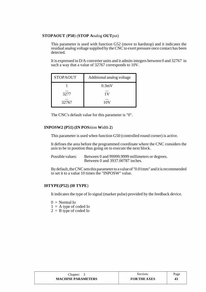
Section:
43MACHINE PARAMETERSPageChapter: 3
STOPAOUT (P50) (STOP Analog OUTput)
This parameter is used with function G52 (move to hardstop) and it indicates theresidual analog voltage supplied by the CNC to exert pressure once contact has beendetected.
It is expressed in D/A converter units and it admits integers between 0 and 32767 insuch a way that a value of 32767 corresponds to 10V.
STOPAOUT Additional analog voltage
1 0.3mV... ...
3277 1V... ...
32767 10V
The CNC's default value for this parameter is "0".
INPOSW2 (P51) (IN POSition Width 2)
This parameter is used when function G50 (controlled round corner) is active.
It defines the area before the programmed coordinate where the CNC considers theaxis to be in position thus going on to execute the next block.
Possible values: Between 0 and 99999.9999 millimeters or degrees.Between 0 and 3937.00787 inches.
By default, the CNC sets this parameter to a value of "0.01mm" and it is recommendedto set it to a value 10 times the "INPOSW" value.
I0TYPE(P52) (I0 TYPE)
It indicates the type of Io signal (marker pulse) provided by the feedback device.
0 = Normal Io1 = A type of coded Io2 = B type of coded Io
FOR THE AXES

Chapter: 3Page Section:
44 MACHINE PARAMETERS FOR THE AXES
ABSOFF (P53) (ABSolute OFFset)
The CNC takes this parameter into consideration when parameter "I0TYPE" (P52)is set with a value other than "0".
Thes scales having a coded Io (semi-absolute reference mark) indicate the machineposition with respect to the "zero" of the scale.
In order for the CNC to show the position of the axes with respect to the machinereference zero (home), this parameter must be assigned the position value (coordinate)of the machine reference zero (point "M") with respect to the "zero" of the scale "point"C").
Possible values: Between 0 and 99999.9999 millimeters.Between 0 and 3937.00787 inches
The default value for this parameter is "0".
MINMOVE (P54) (MINinum MOVEment)
This parameter has to do with the axis logic outputs "ANT1" thru "ANT6".
If the axis move is smaller than the value indicated by this machine parameter"MINMOVE", the corresponding axis logic output "ANT1 thru "ANT6" goes high.
Possible values: Between 0 and 99999.9999 millimeters or degrees.Between 0 and 3937.00787 inches
The default value for this parameter is "0".
ROLLOVER (P55)
This machine parameter is taken into account when the axis has been set as rotary,"AXISTPYE (P0) = 2 or 3". It indicates whether the rotary axis is also rollover or not.
Possible values: YES / NO
The default value for this parameter is "YES".
SERCOSID (P56)
Not being used at this time, it is reserved for future applications.
It must always be set to "0".

Section:
45MACHINE PARAMETERSPageChapter: 3
FOR THE AXES
EXTMULT (P57) (EXTernal MULTiplier)
This parameter is to be used when utilizing a semi-absolute feedback system (withcoded Io).
It indicates the relationship between the mechanical pitch or that of the glassgraduation with the electrical pitch or the period of the feedback signal supplied to theCNC.
Glass graduation pitch (mechanical pitch)EXTMULT = --------------------------------------------------------
feedback signal period (electrical pitch)
For instance, the FAGOR "FOT" linear scale has a glass graduation pitch of 100 µmwhile its output signals have an electrical pitch of 20 µm.
100EXTMULT = ------ = 5
20
Values to be allocated for semi-absolute Fagor scales (with coded Io):
COS, COVS, MOVS, FOS .............. EXTMULT = 1COC, COVC, MOVC, FOC .............. EXTMULT = 1COX, COVX, MOVX, FOT .............. EXTMULT = 5
The default value for this parameter is "0".

Chapter: 3Page Section:
46 MACHINE PARAMETERS
3.3.3 SPINDLE MACHINE PARAMETERS
3.3.3.1 MACHINE PARAMETERS FOR MAIN SPINDLE
SPDLTYPE (P0) (SPinDLe TYPE)
Indicates the type of spindle output being used.
0 = ±10V DC.1 = 2-digit BCD code.2 = 8-digit BCD code.
By default, the CNC assumes ±10V D.C. (value 0).
DFORMAT (P1) (Display FORMAT)
Indicates the display format for the spindle.
0 = In 4 digits.1 = In 5 digits.2 = In format 4.3.3 = In format 5.3.4 = Not displayed.
By default, the CNC will assume a value of 0 for this parameter.
MAXGEAR1 (P2) (MAXimum speed of GEAR 1)
Indicates the maximum spindle speed assigned to the 1st range (M41).
It is given in revolutions per minutes (r.p.m.) between 0 and 65535.
By default, the CNC assumes a value of 1000 r.p.m. for this parameter.
MAXGEAR2 (P3) (MAXimum speed of GEAR 2)
Indicates the maximum spindle speed assigned to the 2nd range (M42).
It is given in revolutions per minutes (r.p.m.) between 0 and 65535.
By default, the CNC assumes a value of 2000 r.p.m. for this parameter.
MAXGEAR3 (P4) (MAXimum speed of GEAR 3)
Indicates the maximum spindle speed assigned to the 3rd range (M43).
It is given in revolutions per minutes (r.p.m.) between 0 and 65535.
By default, the CNC assumes a value of 3000 r.p.m. for this parameter.
FOR THE MAIN SPINDLE

Section:
47MACHINE PARAMETERSPageChapter: 3
MAXGEAR4 (P5) (MAXimum speed of GEAR 4)
Indicates the maximum spindle speed assigned to the 4th range (M44).
It is given in revolutions per minutes (r.p.m.) between 0 and 65535.
By default, the CNC assumes a value of 4000 r.p.m. for this parameter.
The value assigned to “MAXGEAR1” must be the lowest speed range and the oneassigned to “MAXGEAR4” that of the highest speed range. When not all four rangesare required, use the lower ones starting from “MAXGEAR1” and assign the highestone to the unused ranges.
AUTOGEAR (P6) (AUTOmatic GEAR change)
Indicates whether the change of range is generated automatically or not by the CNCactivating the M functions M41, M42, M43 and M44.
NO = It is NOT done automatically.YES = It is done automatically.
By default, the CNC assumes NO for this parameter.
POLARM3 (P7) (POLARity for M3)POLARM4 (P8) (POLARity for M4)
Indicates the sign of the spindle analog for M03 and M04.
+ = Positive analog.- = Negative analog.
If the same value is assigned to both parameters, the CNC will output a single polarity(0V to 10V) signal with the indicated sign.
By default, the CNC assigns “+” to “POLARM3” and “-” to “POLARM4”.
SREVM05 (P9) (Spindle REVerse needs M05)
This parameter is used with a Mill model CNC.
Indicates whether it is necessary or not to stop the spindle (M05) when reversingrotation direction during a tapping canned cycle (G84).
NO = M5 is NOT necessary.YES = M5 is necessary.
By default, the CNC assumes YES.
FOR THE MAIN SPINDLE

Chapter: 3Page Section:
48 MACHINE PARAMETERS
MINSOVR (P10) (MINimum Spindle OVeRride)MAXSOVR (P11) (MAXimum Spindle OVeRride)
Indicate the minimum and maximum % applicable to the programmed spindle speed.
Possible values: Integers between 0 and 255.
By default, the CNC assigns a value of 50% to “MINSOVER” and 120% to“MAXSOVR”.
The resulting speed will be limited by the value indicated in the spindle machineparameter: “MAXVOLT1”, “MAXVOLT2”, “MAXVOLT3”,” MAXVOLT4"corresponding to the selected range.
SOVRSTEP (P12) (Spindle OVeRride STEP)
Indicates the incremental step of the spindle speed every time the override keys at theoperator panel are pressed.
Possible values: Integer values between 0 and 255.
By default, the CNC assumes a value of 5 for this parameter.
NPULSES (P13) (Number of PULSES)
Indicates the number of pulses per revolution provided by the spindle encoder. 0means that there is no spindle encoder.
Possible values: Integer values between 0 and 65535.
By default, the CNC assumes a value of 1000 for this parameter.
DIFFBACK (P14) (DIFferential FeedBACK)
Indicates whether the spindle encoder uses differential signals (double ended) or not.
NO = They are NOT differential signals.YES = They are differential signals.
By default, the CNC assumes YES.
FBACKAL (P15) (FeedBACK ALarm)
Indicates whether the feedback alarm is OFF or ON.
OFF = Alarm off.ON = Alarm on.
By default, the alarm is ON.
FOR THE MAIN SPINDLE

Section:
49MACHINE PARAMETERSPageChapter: 3
AXISCHG (P16) (AXIS CHanGe)
Indicate the counting direction of spindle encoder. If correct, leave it as is; if not,change it from YES to NO or viceversa.If this parameter is changed, parameter “LOOPCHG” (P26) must also be changed sothe spindle does not “run away”.
Possible values: YES and NO.
By default, the CNC assumes NO.
DWELL (P17)
Indicates the dwell from the moment the “ENABLE” signal is activated until theanalog voltage is sent out.
It is given in milliseconds and it admits integer values between 0 and 65535.
By default, the CNC assumes a value of 0 (no dwell).
ACCTIME (P18) (ACCeleration TIME)
This parameter is used when working with the spindle in closed loop and it indicatesthe acceleration time given to reach the maximum speed (MAXVOLT1 thruMAXVOLT4) in each range. This value also represents the deceleration time.
Possible integer values between 0 and 65535 milliseconds.
The default value for this parameter is 0 (no acceleration or deceleration).
INPOSW (P19) (IN POSition Width)
Indicates the width of the IN POSITION zone where the CNC considers the spindleto be in position when working in closed loop (M19).
Possible values: 0 thru 99999.99999 degrees.
By default, the CNC assumes a value of 0.01 degrees.
FOR THE MAIN SPINDLE

Chapter: 3Page Section:
50 MACHINE PARAMETERS
INPOTIME (P20) (IN POsition TIME)
Indicates the time period that the spindle must remain in the “IN POSITION” zone inorder to consider it to be in position.
This prevents the CNC from considering the spindle to be in position and executingthe next block on those machines where the spindle could just overshoot the “INPOSITION” zone.
It is given in milliseconds and it admits any integer value between 0 and 65535.
By default, the CNC assumes a value of 0 for this parameter.
MAXFLWE1 (P21) (MAXimum FoLloWing Error)
Indicates the maximum following error allowed for the spindle when moving in closedloop (M19).
Possible values: 0 thru 99999.99999 degrees.
By default, the CNC assumes a value of 30 degrees.
MAXFLWE2 (P22) (MAXimum FoLloWing Error)
Indicates the maximum following error allowed for the spindle when stopped in closedloop (M19).
Possible values: 0 thru 99999.99999 degrees.
By default, the CNC assumes a value of 0.1 degrees.
PROGAIN (P23) (PROportional GAIN)
Indicates, the value of the Proportional Gain in millivolts per degree and it admitsinteger values between 0 and 65535.
Its value represents the analog voltage corresponding to a following error of 1 degreewhen working in closed loop (M19).
This value is taken for the 1st range of spindle speeds and the CNC calculates the restof the values for the other ranges.
By default, the CNC assumes a value of 1000mv/degree.
FOR THE MAIN SPINDLE

Section:
51MACHINE PARAMETERSPageChapter: 3
Example:
Spindle machine parameter “MAXGEAR1” = 500 rev/min. The desired speedfor a 1 degree of following error is S = 1000°/min (2.778 rev/rpm).
Analog voltage for spindle drive: 9.5 V. for 500 rpm.
Analog voltage corresponding to S = 1000°/min (2.778 rpm):
9.5 V.Analog = ---------------- x 2.778 rev/min. = 52,782 mV.
500 rev/min.
Therefore, “PROGAIN” = 53
DERGAIN (P24) (DERivative GAIN)
Indicates the value of the Derivative Gain. It is given in mV/10msec. and it admitsvalues between 0 and 65535.
Its value represents the analog voltage (in millivolts) corresponding to a change infollowing error of 1mm (0.040 inches) in 10 milliseconds. This analog voltage will beadded to the one calculated for the the Proportional Gain.
It is a good idea to also use the acc./dec. machine parameter “ACCTIME” for thespindle (with a value other than 0) if this gain is to be applied.
By default, the CNC will assume a value of 0 (derivative gain not applied).
FFGAIN (P25) (Feed-Forward GAIN)
Indicates the % of the analog voltage due to the programmed feedrate. The rest willdepend upon the following error. Both the Proportional and Derivative gains will beapplied onto this following error.
The Feed-Forward Gain allows to improve the positioning loop minimizing thefollowing error, but it should not be used when the “ACCTIME” machine parameterfor the spindle is active (acc/dec. being applied).
Analogoutput
Feedback
FFGAIN
PROGAIN
DERGAIN
++
-
+
+
ProgrammedFeedrate
FOR THE MAIN SPINDLE

Chapter: 3Page Section:
52 MACHINE PARAMETERS
Possible values: Integers between 0 and 100.
Usually, a value between 40% and 60% is assigned depending mainly on the type ofmachine and its characteristics.
By default, the CNC assumes a value of 0 for this parameter (no Feed-Forward gainapplied).
LOOPCHG (P26) (LOOP CHanGe)
Indicates the sign of the analog output. If correct, leave it as is; if not, change it fromYES to NO or viceversa.
Possible values: YES and NO.
By default, the CNC assumes NO.
MINANOUT (P27) (MINimum ANalog OUTput)
Indicates the minimum value for the spindle analog output.
It is given in D/A converter units and it admits integer values between 0 and 32767which corresponds to an analog voltage of 10V.
MINANOUT Minimum Analog
1 0.3 mV.... .....
3277 1 V.... .....
32767 10 V.
By default, the CNC assumes a value of 0 for this parameter.
SERVOFF (P28) (SERVo OFFset)
Indicates the analog offset value for the spindle drive.
It is given in D/A converter units and it admits integer values between 0 and +32767which corresponds to an analog voltage of +10V.
SERVOFF Offset
-32767 -10 V.... .....
-3277 -1 V.... .....1 0.3 mV.... .....
3277 1 V.... .....
32767 10 V.
By default, the CNC assumes a value of 0 (no offset being applied).
FOR THE MAIN SPINDLE

Section:
53MACHINE PARAMETERSPageChapter: 3
LOSPDLIM (P29) (LOwer SPinDle LIMit)UPSPDLIM (P30) (UPper SPinDle LIMit)
Indicate the upper and lower limits of the actual spindle speed so the CNC can “notify”the PLC (by means of the “REVOK” signal) that the actual spindle rpms are the sameas the programmed ones.
It is given in % and it admits integer values between 0 and 255.
By default, the CNC assigns a value of 50 to “LOSPDLIM” and a value of 150 to“UPSPDLIM”.
DECINPUT (P31) (DECeleration INPUT)
Indicates whether or not the spindle has a home switch to synchronize the spindlewhen working in M19.
NO = It has NO home switch.YES = It has a home switch.
By default, the CNC assumes YES.
REFPULSE (P32) (REFerence PULSE)
Indicates the type of marker pulse Io to synchronize the spindle when working in M19.
+ = Positive pulse (5V).- = Negative pulse (0V).
By default, the CNC assumes “+”.
REFDIREC (P33) (REFerencing DIRECtion)
Indicates the rotating direction when synchronizing the spindle during M19.
+ = Positive direction.- = Negative direction.
By default, the CNC assumes “+”.
REFEED1 (P34) (REferencing FEEDrate 1)
Indicates the spindle’s positioning speed when in M19 and the synchronizing speeduntil it finds the home switch.
Possible values: 0.00001 thru 199999.99999 degrees/min.
By default, the CNC assumes a value of 9000 degrees/min.
FOR THE MAIN SPINDLE

Chapter: 3Page Section:
54 MACHINE PARAMETERS
REFEED2 (P35) (REferencing FEEDrate 2)
Indicates the synchronizing speed of the spindle after hitting the home switch and untilit finds the marker pulse.
Possible values: 0.00001 thru 99999.99999 degrees/min.
By default, the CNC assumes a value of 360 degrees/min.
REFVALUE (P36) (REFerence VALUE)
Indicates the position value assigned to the reference point of the spindle (home ormarker pulse).
Possible values: ±99999.99999 degrees.
By default, the CNC assumes a value of 0.
MAXVOLT1 (P37) (MAXimum VOLTage gear 1)
Indicates the analog voltage corresponding to the maximum speed of range 1.
It is given in millivolts and it admits any integer between 0 and 9999.
By default, the CNC assumes a value of 9500 (9.5 V).
MAXVOLT2 (P38) (MAXimum VOLTage gear 2)
Indicates the analog voltage corresponding to the maximum speed of range 2.
It is given in millivolts and it admits any integer between 0 and 9999.
By default, the CNC assumes a value of 9500 (9.5 V).
MAXVOLT3 (P39) (MAXimum VOLTage gear 3)
Indicates the analog voltage corresponding to the maximum speed of range 3.
It is given in millivolts and it admits any integer between 0 and 9999.
By default, the CNC assumes a value of 9500 (9.5 V).
MAXVOLT4 (P40) (MAXimum VOLTage gear 4)
Indicates the analog voltage corresponding to the maximum speed of range 4.
It is given in millivolts and it admits any integer between 0 and 9999.
The default setting of this parameter is 9500 (9.5V).
FOR THE MAIN SPINDLE

Section:
55MACHINE PARAMETERSPageChapter: 3
GAIN UNIT (P41)
It indicates the units of the “PROGAIN” (P23) and “DERGAIN” (P24) parametersfor the spindle.
0 = millivolts/degree1 = millivolts/0.01 degree
This parameter is used when working with the spindle in closed loop.
A value of “1” will be assigned when the analog voltage corresponding to a followingerror of 1 degree is very small. Therefore, the adjustment of machine parameters“PROGAIN” and “DERGAIN” will be more critical (sensitive).
The default value for this parameter is 0 (mV/degree).
By default, the CNC assumes a value of 9500 (9.5 V).
ACFGAIN (P42) (AC-Forward GAIN)
Indicates whether the "DERGAIN (P24)" value is to be applied onto the variationsof following error(derivative gain) or onto the variations of programmed feedrate(AC-forward).
NO = It is applied onto the variations of following error (derivative gain).
YES = It is applied onto the variations of programmed feedrate due to ACC/DEC (AC-forward).
The default value of this parameter is "NO".
PROGAIN
DERGAIN
FFGAIN
Analog output+
-
++
+
Feedback
FFGAIN
Analog output+
+
+
DERGAIN
Feedback
+
-
PROGAIN
ProgrammedFeedrate
ProgrammedFeedrate
FOR THE MAIN SPINDLE

Chapter: 3Page Section:
56 MACHINE PARAMETERS
M19TYPE (P43)
This parameter sets the type of spindle orient (M19) available.
It indicates whether the spindle must be homed when switching from open to closedloop or it is enough to home it once on power-up.
0 = The spindle must be homed every time when switching from open to closedloop.
1 = It is enough to home the spindle once on power-up.
The default value for this parameter is "0".
FOR THE MAIN SPINDLE

Section:
57MACHINE PARAMETERSPageChapter: 3
3.3.3.2 MACHINE PARAMETERS FOR THE SECOND SPINDLE
These parameters are available on the lathe model CNC.
SPDLTYPE (P0) (SPinDLe TYPE)
Indicates the type of spindle output being used.
0 = ±10V DC.1 = 2-digit BCD code.2 = 8-digit BCD code.
By default, the CNC assumes ±10V D.C. (value 0).
DFORMAT (P1) (Display FORMAT)
Not being used at this time. Reserved for future applications.
MAXGEAR1 (P2) (MAXimum speed of GEAR 1)
Indicates the maximum spindle speed assigned to the 1st range (M41).
It is given in revolutions per minutes (r.p.m.) between 0 and 65535. By default, theCNC assumes a value of 1000 r.p.m. for this parameter.
MAXGEAR2 (P3) (MAXimum speed of GEAR 2)
Indicates the maximum spindle speed assigned to the 2nd range (M42).
It is given in revolutions per minutes (r.p.m.) between 0 and 65535. By default, theCNC assumes a value of 2000 r.p.m. for this parameter.
MAXGEAR3 (P4) (MAXimum speed of GEAR 3)
Indicates the maximum spindle speed assigned to the 3rd range (M43).
It is given in revolutions per minutes (r.p.m.) between 0 and 65535. By default, theCNC assumes a value of 3000 r.p.m. for this parameter.
MAXGEAR4 (P5) (MAXimum speed of GEAR 4)
Indicates the maximum spindle speed assigned to the 4th range (M44).
It is given in revolutions per minutes (r.p.m.) between 0 and 65535. By default, theCNC assumes a value of 4000 r.p.m. for this parameter.
The value assigned to “MAXGEAR1” must be the lowest speed range and the oneassigned to “MAXGEAR4” that of the highest speed range. When not all four rangesare required, use the lower ones starting from “MAXGEAR1” and assign the highestone to the unused ranges.
FOR THE 2nd SPINDLE

Chapter: 3Page Section:
58 MACHINE PARAMETERS
AUTOGEAR (P6) (AUTOmatic GEAR change)
Indicates whether the change of range is generated automatically or not by the CNCactivating the M functions M41, M42, M43 and M44.
NO = It is NOT done automatically.YES = It is done automatically.
By default, the CNC assumes NO for this parameter.
POLARM3 (P7) (POLARity for M3)POLARM4 (P8) (POLARity for M4)
Indicates the sign of the spindle analog for M03 and M04.
+ = Positive analog.- = Negative analog.
If the same value is assigned to both parameters, the CNC will output a single polarity(0V to 10V) signal with the indicated sign.
By default, the CNC assigns “+” to “POLARM3” and “-” to “POLARM4”.
SREVM05 (P9)MINSOVR (P10)MAXSOVR (P11)SOVRSTEP (P12)
Not being used at this time. Reserved for future applications.
NPULSES (P13) (Number of PULSES)
Indicates the number of pulses per revolution provided by the spindle encoder. 0means that there is no spindle encoder.
Possible values: Integer values between 0 and 65535.
By default, the CNC assumes a value of 1000 for this parameter.
DIFFBACK (P14) (DIFferential FeedBACK)
Indicates whether the spindle encoder uses differential signals (double ended) or not.
NO = They are NOT differential signals.YES = They are differential signals.
By default, the CNC assumes YES.
FOR THE 2nd SPINDLE

Section:
59MACHINE PARAMETERSPageChapter: 3
FBACKAL (P15) (FeedBACK ALarm)
Indicates whether the feedback alarm is OFF or ON.
OFF = Alarm off.ON = Alarm on.
By default, the alarm is ON.
AXISCHG (P16) (AXIS CHanGe)
Indicate the counting direction of spindle encoder. If correct, leave it as is; if not,change it from YES to NO or viceversa.If this parameter is changed, parameter “LOOPCHG” (P26) must also be changed sothe spindle does not “run away”.
Possible values: YES and NO.
By default, the CNC assumes NO.
DWELL (P17)
Indicates the dwell from the moment the “ENABLE” signal is activated until theanalog voltage is sent out.
It is given in milliseconds and it admits integer values between 0 and 65535.
By default, the CNC assumes a value of 0 (no dwell).
ACCTIME (P18) (ACCeleration TIME)
This parameter is used when working with the spindle in closed loop and it indicatesthe acceleration time given to reach the maximum speed (MAXVOLT1 thruMAXVOLT4) in each range. This value also represents the deceleration time.
Possible integer values between 0 and 65535 milliseconds.
The default value for this parameter is 0 (no acceleration or deceleration).
INPOSW (P19) (IN POSition Width)
Indicates the width of the IN POSITION zone where the CNC considers the spindleto be in position when working in closed loop (M19).
Possible values: 0 thru 99999.99999 degrees.
By default, the CNC assumes a value of 0.01 degrees.
FOR THE 2nd SPINDLE

Chapter: 3Page Section:
60 MACHINE PARAMETERS
INPOTIME (P20) (IN POsition TIME)
Indicates the time period that the spindle must remain in the “IN POSITION” zone inorder to consider it to be in position.
This prevents the CNC from considering the spindle to be in position and executingthe next block on those machines where the spindle could just overshoot the “INPOSITION” zone.
It is given in milliseconds and it admits any integer value between 0 and 65535.
By default, the CNC assumes a value of 0 for this parameter.
MAXFLWE1 (P21) (MAXimum FoLloWing Error)
Indicates the maximum following error allowed for the spindle when moving in closedloop (M19).
Possible values: 0 thru 99999.99999 degrees.
By default, the CNC assumes a value of 30 degrees.
MAXFLWE2 (P22) (MAXimum FoLloWing Error)
Indicates the maximum following error allowed for the spindle when stopped in closedloop (M19).
Possible values: 0 thru 99999.99999 degrees.
By default, the CNC assumes a value of 0.1 degrees.
PROGAIN (P23) (PROportional GAIN)
Indicates, the value of the Proportional Gain in millivolts per degree and it admitsinteger values between 0 and 65535.
Its value represents the analog voltage corresponding to a following error of 1 degreewhen working in closed loop (M19).
This value is taken for the 1st range of spindle speeds and the CNC calculates the restof the values for the other ranges.
By default, the CNC assumes a value of 1000mv/degree.
FOR THE 2nd SPINDLE

Section:
61MACHINE PARAMETERSPageChapter: 3
Example:
Spindle machine parameter “MAXGEAR1” = 500 rev/min. The desired speedfor a 1 degree of following error is S = 1000°/min (2.778 rev/rpm).
Analog voltage for spindle drive: 9.5 V. for 500 rpm.
Analog voltage corresponding to S = 1000°/min (2.778 rpm):
9.5 V.Analog = ---------------- x 2.778 rev/min. = 52,782 mV.
500 rev/min.
Therefore, “PROGAIN” = 53
DERGAIN (P24) (DERivative GAIN)
Indicates the value of the Derivative Gain. It is given in mV/10msec. and it admitsvalues between 0 and 65535.
Its value represents the analog voltage (in millivolts) corresponding to a change infollowing error of 1mm (0.040 inches) in 10 milliseconds. This analog voltage will beadded to the one calculated for the the Proportional Gain.
It is a good idea to also use the acc./dec. machine parameter “ACCTIME” for thespindle (with a value other than 0) if this gain is to be applied.
By default, the CNC will assume a value of 0 (derivative gain not applied).
FFGAIN (P25) (Feed-Forward GAIN)
Indicates the % of the analog voltage due to the programmed feedrate. The rest willdepend upon the following error. Both the Proportional and Derivative gains will beapplied onto this following error.
The Feed-Forward Gain allows to improve the positioning loop minimizing thefollowing error, but it should not be used when the “ACCTIME” machine parameterfor the spindle is active (acc/dec. being applied).
Analogoutput
Feedback
FFGAIN
PROGAIN
DERGAIN
++
-
+
+
ProgrammedFeedrate
FOR THE 2nd SPINDLE

Chapter: 3Page Section:
62 MACHINE PARAMETERS
Possible values: Integers between 0 and 100.
Usually, a value between 40% and 60% is assigned depending mainly on the type ofmachine and its characteristics.
By default, the CNC assumes a value of 0 for this parameter (no Feed-Forward gainapplied).
LOOPCHG (P26) (LOOP CHanGe)
Indicates the sign of the analog output. If correct, leave it as is; if not, change it fromYES to NO or viceversa.
Possible values: YES and NO.
By default, the CNC assumes NO.
MINANOUT (P27) (MINimum ANalog OUTput)
Indicates the minimum value for the spindle analog output.
It is given in D/A converter units and it admits integer values between 0 and 32767which corresponds to an analog voltage of 10V.
MINANOUT Minimum Analog
1 0.3 mV.... .....
3277 1 V.... .....
32767 10 V.
By default, the CNC assumes a value of 0 for this parameter.
SERVOFF (P28) (SERVo OFFset)
Indicates the analog offset value for the spindle drive.
It is given in D/A converter units and it admits integer values between 0 and +32767which corresponds to an analog voltage of +10V.
SERVOFF Offset
-32767 -10 V.... .....
-3277 -1 V.... .....1 0.3 mV.... .....
3277 1 V.... .....
32767 10 V.
By default, the CNC assumes a value of 0 (no offset being applied).
FOR THE 2nd SPINDLE

Section:
63MACHINE PARAMETERSPageChapter: 3
LOSPDLIM (P29) (LOwer SPinDle LIMit)UPSPDLIM (P30) (UPper SPinDle LIMit)
Indicate the upper and lower limits of the actual spindle speed so the CNC can “notify”the PLC (by means of the “REVOK” signal) that the actual spindle rpms are the sameas the programmed ones.
It is given in % and it admits integer values between 0 and 255.
By default, the CNC assigns a value of 50 to “LOSPDLIM” and a value of 150 to“UPSPDLIM”.
DECINPUT (P31) (DECeleration INPUT)
Indicates whether or not the spindle has a home switch to synchronize the spindlewhen working in M19.
NO = It has NO home switch.YES = It has a home switch.
By default, the CNC assumes YES.
REFPULSE (P32) (REFerence PULSE)
Indicates the type of marker pulse Io to synchronize the spindle when working in M19.
+ = Positive pulse (5V).- = Negative pulse (0V).
By default, the CNC assumes “+”.
REFDIREC (P33) (REFerencing DIRECtion)
Indicates the rotating direction when synchronizing the spindle during M19.
+ = Positive direction.- =
Negative direction.
By default, the CNC assumes “+”.
REFEED1 (P34) (REferencing FEEDrate 1)
Indicates the spindle’s positioning speed when in M19 and the synchronizing speeduntil it finds the home switch.
Possible values: 0.00001 thru 199999.99999 degrees/min.
By default, the CNC assumes a value of 9000 degrees/min.
FOR THE 2nd SPINDLE

Chapter: 3Page Section:
64 MACHINE PARAMETERS
REFEED2 (P35) (REferencing FEEDrate 2)
Indicates the synchronizing speed of the spindle after hitting the home switch and untilit finds the marker pulse.
Possible values: 0.00001 thru 99999.99999 degrees/min.
By default, the CNC assumes a value of 360 degrees/min.
REFVALUE (P36) (REFerence VALUE)
Indicates the position value assigned to the reference point of the spindle (home ormarker pulse).
Possible values: ±99999.99999 degrees.
By default, the CNC assumes a value of 0.
MAXVOLT1 (P37) (MAXimum VOLTage gear 1)
Indicates the analog voltage corresponding to the maximum speed of range 1.
It is given in millivolts and it admits any integer between 0 and 9999.
By default, the CNC assumes a value of 9500 (9.5 V).
MAXVOLT2 (P38) (MAXimum VOLTage gear 2)
Indicates the analog voltage corresponding to the maximum speed of range 2.
It is given in millivolts and it admits any integer between 0 and 9999.
By default, the CNC assumes a value of 9500 (9.5 V).
MAXVOLT3 (P39) (MAXimum VOLTage gear 3)
Indicates the analog voltage corresponding to the maximum speed of range 3.
It is given in millivolts and it admits any integer between 0 and 9999.
By default, the CNC assumes a value of 9500 (9.5 V).
MAXVOLT4 (P40) (MAXimum VOLTage gear 4)
Indicates the analog voltage corresponding to the maximum speed of range 4.
It is given in millivolts and it admits any integer between 0 and 9999.
The default setting of this parameter is 9500 (9.5V).
FOR THE 2nd SPINDLE

Section:
65MACHINE PARAMETERSPageChapter: 3
GAIN UNIT (P41)
It indicates the units of the “PROGAIN” (P23) and “DERGAIN” (P24) parametersfor the spindle.
0 = millivolts/degree1 = millivolts/0.01 degree
This parameter is used when working with the spindle in closed loop.
A value of “1” will be assigned when the analog voltage corresponding to a followingerror of 1 degree is very small. Therefore, the adjustment of machine parameters“PROGAIN” and “DERGAIN” will be more critical (sensitive).
The default value for this parameter is 0 (mV/degree).
By default, the CNC assumes a value of 9500 (9.5 V).
ACFGAIN (P42) (AC-Forward GAIN)
Indicates whether the "DERGAIN (P24)" value is to be applied onto the variationsof following error(derivative gain) or onto the variations of programmed feedrate(AC-forward).
NO = It is applied onto the variations of following error (derivative gain).
YES = It is applied onto the variations of programmed feedrate due to ACC/DEC (AC-forward).
The default value of this parameter is "NO".
PROGAIN
DERGAIN
FFGAIN
Analog output+
-
++
+
Feedback
FFGAIN
Analog output+
+
+
DERGAIN
Feedback
+
-
PROGAIN
ProgrammedFeedrate
ProgrammedFeedrate
FOR THE 2nd SPINDLE

Chapter: 3Page Section:
66 MACHINE PARAMETERS
M19TYPE (P43)
This parameter sets the type of spindle orient (M19) available.
It indicates whether the spindle must be homed when switching from open to closedloop or it is enough to home it once on power-up.
0 = The spindle must be homed every time when switching from open to closedloop.
1 = It is enough to home the spindle once on power-up.
The default value for this parameter is "0".
FOR THE 2nd SPINDLE

Section:
67MACHINE PARAMETERSPageChapter: 3
3.3.3.3 MACHINE PARAMETERS FOR AUXILIARY SPINDLE
MAXSPEED (P0) (Maximum SPEED)
Indicates the maximum speed of the auxiliary spindle. It is given in rpms and it admitsany integer value between 0 and 65535.
Its default value is 1000 rpms.
SPDLOVR (P1) (SPindle OVeRide)
Indicates whether or not the spindle override buttons of the front panel affects thecurrent speed of the auxiliary spindle when active.
NO = They do not alter the current spindle speed.YES= They do alter it. The CNC will apply the values set for machine
parameters for the main spindle "MINSOVR" (P10), "MAXOVR"(P11) and "SOVRSTEP" (P12).
By default, This parameter is set to NO.
MINANOUT (P2) (MINimum ANalog OUTput)
Indicates the minimum value for the spindle analog output.
It is given in D/A converter units and it admits integer values between 0 and 32767which corresponds to an analog voltage of 10V.
MINANOUT Minimum Analog
1 0.3 mV.... .....
3277 1 V.... .....
32767 10 V.
By default, the CNC assumes a value of 0 for this parameter.
FOR AUXILIARY SPINDLE

Chapter: 3Page Section:
68 MACHINE PARAMETERS
SERVOFF (P3) (SERVo OFFset)
Indicates the analog offset value for the spindle drive.
It is given in D/A converter units and it admits integer values between 0 and +32767which corresponds to an analog voltage of +10V.
SERVOFF Offset
-32767 -10 V.... .....
-3277 -1 V.... .....1 0.3 mV.... .....
3277 1 V.... .....
32767 10 V.
By default, the CNC assumes a value of 0 (no offset being applied).
MAXVOLT (P4) (MAXimum VOLTage)
Indicates the analog voltage corresponding to the maximum speed defined by machineparameter "MAXSPEED".
It is given in millivolts and it admits any integer value between 0 and 9999.
Its default value is 9500 (9.5V).
FOR AUXILIARY SPINDLE

Section:
69MACHINE PARAMETERSPageChapter: 3
3.3.4 MACHINE PARAMETERS FOR THE SERIAL PORTS
BAUDRATE (P0)
Indicates the communication speed, in baud, between the CNC and the peripherals.The code is:
0 = 110 baud 1 = 150 baud 2 = 300 baud 3 = 600 baud 4 = 1200 baud 5 = 2400 baud 6 = 4800 baud 7 = 9600 baud 8 = 19200 baud 9 = 38400 baud (only when using CPU-Turbo)10 = reserved11 = reserved12 = reserved
By default, the CNC assumes a value of 7 (9600 baud).
NBITSCHR (P1) (Number of BITS per CHaRacter)
Indicates the number of data bits per transmitted character.
0 = Uses the 7 least significant bits of an 8-bit character. It is used whentransmitting standard ASCII characters.
1 = Uses all 8 bits of the transmitting character. Used when transmittingspecial characters whose codes are greater than 127.
By default, the CNC assumes a value of 1 (8 bits).
PARITY (P2)
Indicates the type of parity check used.
0 = No parity.1 = Odd parity.2 = Even parity.
By default, the CNC assumes a value of 0 (no parity).
FOR SERIAL PORTS

Chapter: 3Page Section:
70 MACHINE PARAMETERS
STOPBITS (P3)
Indicates the number of stop bits at the end of each transmitted word.
0 = 1 STOP bit.1 = 2 STOP bits.
By default, the CNC assumes a value of 0 (1 STOP bit).
PROTOCOL (P4)
Indicates the type of communications protocol to be used.
0 = Communications protocol for general device.1 = DNC protocol.2 = Communications protocol for FAGOR floppy disc unit.
By default, the CNC assumes a value of 1. (DNC protocol).
PWONDNC (P5) (PoWer-ON DNC)
Indicates whether the DNC feature will be active on power-up or not.
NO = Not active on power-up.YES = Active on power-up
By default, the DNC feature WILL be active on power-up (YES).
DNCDEBUG (P6)
Indicates whether the debugging feature for DNC communications is active or not.When this feature is NOT active, the CNC WILL abort DNC communications if theyare not established within an internally set period of time.
It is advisable to use this safety feature in all DNC communications. It could bedeactivated in the debugging process.
NO = Debug NOT active. CNC time-out active.YES = Debug active. CNC time-out not active.
By default, the DEBUG will NOT be active.
ABORTCHR (P7) (ABORT CHaRacter)
Indicates the character used to abort communications with general peripheral device.
0 = CAN1 = EOT
By default, the CNC assumes a value of 0 for this parameter.
FOR SERIAL PORTS

Section:
71MACHINE PARAMETERSPageChapter: 3
EOLCHR (P8) (End Of Line CHaRacter)
Indicates the character used to indicate “end of line” when communicating withgeneral peripheral device.
0 = LF1 = CR2 = LF-CR3 = CR-LF
By default, the CNC assumes a value of 0.
EOFCHR (P9) (End Of File CHaRacter)
Indicates the character used to indicate “end of text” (end of file) when communicatingwith a general peripheral device.
0 = EOT1 = ESC2 = SUB3 = ETX
By default, the CNC assumes a value of 0 for this parameter.
XONXOFF (P10)
Indicates whether the XON-XOFF communications protocol is active or not whenoperating with a generic peripheral.
ON = It is active.OFF = It is NOT active.
By default, XON-XOFF is ON.
FOR SERIAL PORTS

Chapter: 3Page Section:
72 MACHINE PARAMETERS
3.3.5 MACHINE PARAMETERS FOR THE PLC
WDGPRG (P0) (Watch-DoG PRoGram)
Indicates the Watch-dog time-out period for the main PLC program.
It is given in milliseconds and it admits integer values between 0 and 65535.
By default, the CNC assumes a value of 0 for this parameter.
WDGPER (P1) (Watch-DoG PERiodic)
Indicates the Watch-Dog time-out period for the periodic module of the PLC.
It is given in milliseconds and it admits integer values between 0 and 65535.
By default, the CNC assumes a value of 0 for this parameter.
USER0 (P2) — — — — — —USER23 (P25)
Parameters “USER0” thru “USER23” do not mean anything to the CNC. They couldcontain the type of information that the OEM may find necessary to customize thismachine, such as:
Information about type of machinePLC program versionEtc.
This information can be accessed from the PLC program by means of the “CNCRD”high-level instruction.
Possible values:
USER0 (P2) thru USER7 (P9) : Integers between 0 and 255.USER8 (P10) thru USER15 (P17) : Integers between 0 and 65535.USER16 (P18) thru USER23 (P25) : ±99999.9999 mm or ±3937.00787 inches.
By default, the CNC assigns a value of 0 to these parameters.
PLC

Section:
73MACHINE PARAMETERSPageChapter: 3
CPUTIME (P26)
This parameter is used when the PLC does not have its own CPU and it indicatesthe time the system CPU dedicates to the PLC.
Possible values: 0 = 1 millisecond every 8 samplings.1 = 1 millisecond every 4 samplings.2 = 1 millisecond every 2 samplings.3 = 1 millisecond every sampling.
The sampling period is determined by the general machine parameter"LOOPTIME".Hence, for a sampling period of 4 msec. and a CPUTIME=0, the system CPUdedicates 1 millsecond every 8 samplings (thus, 32 milliseconds) to the PLC.
The default value for this parameter is "0".
PLCMEM (P27) (PLC MEMORY)
It indicates the percentage (%) of EEPROM memory used to store the PLC program.
This EEPROM memory stores the following information.
* The PLC program as mentioned above.
* The Pages (screens) and Symbols created with the Graphic Editor. The percentageof EEPROM memory space dedicated to this is established by the machineparameter "PAGESMEM".
* The part-programs of the CNC in the remaining free EEPROM memory space.
Possible integer values: between 0 and 100.
The default value for this parameter is 50.
Atention:
Changing this parameter can cause items previously stored in EEPROMmemory to be lost.
To avoid this, proceed as follows:
1.- Transfer the data from the EEPROM to a peripheral or PC.
2.- Change the setting of "PAGESMEM" and "PLCMEM".
3.- Press [SHIFT] [RESET].
4.- Re-enter all the data back into the EEPROM.
PLC

Chapter: 3Page Section:
74 MACHINE PARAMETERS
3.3.6 MISCELLANEOUS (M) FUNCTION TABLE
The number of M functions in this table is determined by the general machine parameter“NMISCFUN”, being possible to define up to 255 M functions.
It must borne in mind that functions: M00, M01, M02, M03, M04, M05, M06, M8, M9,M19, M30, M41, M42, M43 and M44, besides what is idicated in this table, have specificmeanings when programming the CNC.
Each miscellaneous function will be called by its M number.
Possible values: Integers between 0 and 9999. The undefined table elements will beshown as M????.
A subroutine can be associated with each M function and it will be indicated by the letterS.
Possible values: Integers between 0 and 9999. If 0 is assigned to this field, it meansthat there is no associated subroutine.
F1 F2 F4 F5 F6 F7F3
EDIT ERASE LOAD SAVEFIND
M FUNCTION TABLE
Miscellaneous Function Subroutine Customizing Bits
CAP INS
11:50:14
P..... N.....
MODIFY
M???? S0000 00000000M???? S0000 00000000M???? S0000 00000000M???? S0000 00000000M???? S0000 00000000M???? S0000 00000000M???? S0000 00000000M???? S0000 00000000M???? S0000 00000000M???? S0000 00000000M???? S0000 00000000M???? S0000 00000000M???? S0000 00000000M???? S0000 00000000M???? S0000 00000000M???? S0000 00000000M???? S0000 00000000M???? S0000 00000000M???? S0000 00000000M???? S0000 00000000
M FUNCTION TABLE

Section:
75MACHINE PARAMETERSPageChapter: 3
The third field consists of 8 customizing bits called bit0 thru bit7:
* * * * * * * *7) 0)
BIT 0: Indicates whether the CNC must wait or not for the AUX END signal (Mdone) to consider it executed and go on to the next program block
0 = It waits for the AUX END signal.1 = It does NOT wait for AUX END.
BIT 1: Indicates whether the M function is executed before or after the movementblock where it is programmed.
0 = It is executed before the move.1 = It is executed after the move.
BIT 2: Indicates whether the M function interrupts the block preparation (theCNC reads 20 blocks ahead of their execution) or not.
0 = It does NOT interrupt the block preparation.1 = It interrupts the block preparation.
BIT 3: Indicates whether the M function is executed or not after the associatedsubroutine is executed.
0 = It is executed after the associated subroutine.1 = ONLY the associated subroutine is executed.
BIT 4: When bit "2" has been set to "1", it indicates whether block preparationis to be interrupted until the execution of the M function begins or untilit ends (until the M-done signal is received).
0 = It interrupts block preparation until the execution of the "M"function begins.
1 = It interrupts block preparation until the "M-done" signal(AUXEND) is received.
BITs 5 thru 7: Not being used at this time.
When executing an M function which has not been defined in the M table, the programmedfunction will be executed at the beginning of the block and the CNC will “wait” for the“AUXEND” signal to continue the execution of the program.
M FUNCTION TABLE

Chapter: 3Page Section:
76 MACHINE PARAMETERS
3.3.7 LEADSCREW ERROR COMPENSATION TABLE
The CNC will provide a table for each one of the axes having leadscrew compensation. Thistype of compensation is activated by setting machine parameter “LSCRWCOM” for thoseaxes.
The number of points (up to 255) affected by this compensation must be indicated by axis-machine-parameter “NPOINTS”.
P001 X 0.0000 EX 0.0000P002 X 0.0000 EX 0.0000P003 X 0.0000 EX 0.0000P004 X 0.0000 EX 0.0000P005 X 0.0000 EX 0.0000P006 X 0.0000 EX 0.0000P007 X 0.0000 EX 0.0000P008 X 0.0000 EX 0.0000P009 X 0.0000 EX 0.0000P010 X 0.0000 EX 0.0000P011 X 0.0000 EX 0.0000P012 X 0.0000 EX 0.0000P013 X 0.0000 EX 0.0000P014 X 0.0000 EX 0.0000P015 X 0.0000 EX 0.0000P016 X 0.0000 EX 0.0000P017 X 0.0000 EX 0.0000P018 X 0.0000 EX 0.0000P019 X 0.0000 EX 0.0000P020 X 0.0000 EX 0.0000
F1 F2 F4 F5 F6 F7F3
CAP INS MM
11:50:14
P..... N.....
MODIFYEDIT INITIALIZE LOADFIND SAVE MM /INCH
COMPENSATION AXIS X
ERROR POINT POSITION ERROR
Each table parameter represents one leadscrew point to be compensated. Each one defines:
The axis position for that Leadscrew point with respect to Machine Reference ZERO.
Possible values: ±99999.9999 millimeters.±3937.00787 inches.
The leadscrew error in this point.
Possible values: ±99999.9999 millimeters.±3937.00787 inches.
LEADSCREWCOMPENSATION

Section:
77MACHINE PARAMETERSPageChapter: 3
When defining the leadscrew compensation table, the following requirements must be met:
* The axis points must be in sequential order starting from the most negative (leastpositive) point to be compensated.
* For those points outside the compensation zone, the CNC will apply thecompensation value corresponding to the table point closest to them.
* The Machine reference POINT (HOME or marker pulse location) must beassigned an error 0,
* The error difference between two consecutive points must not be greater than thedistance between them (maximum slope= 100%).
LEADSCREWCOMPENSATION

Chapter: 3Page Section:
78 MACHINE PARAMETERS
3.3.8 CROSS COMPENSATION PARAMETER TABLE
This axis offers cross compensation for the axes. To apply it, define the axis causing theposition variations by setting the general machine parameter “MOVAXIS” and define theaxis suffering those position variations by setting the general machine parameter“COMPAXIS”.
Both parameters must be defined for this table to be active. The number of compensationpoints (up to 255) will be defined by setting axis-machine parameter “NPCROSS”.
Each parameter of this table defines:
F1 F2 F4 F5 F6 F7F3
CAP INS MM
11:50:14
P..... N.....
MODIFYEDIT INITIALIZE LOADFIND SAVE MM /INCH
ERRORERROR POINT POTICION
CROSSED COMP. TABLE
P001 X 0.0000 EV 0.0000P002 X 0.0000 EV 0.0000P003 X 0.0000 EV 0.0000P004 X 0.0000 EV 0.0000P005 X 0.0000 EV 0.0000P006 X 0.0000 EV 0.0000P007 X 0.0000 EV 0.0000P008 X 0.0000 EV 0.0000P009 X 0.0000 EV 0.0000P010 X 0.0000 EV 0.0000P011 X 0.0000 EV 0.0000P012 X 0.0000 EV 0.0000P013 X 0.0000 EV 0.0000P014 X 0.0000 EV 0.0000P015 X 0.0000 EV 0.0000P016 X 0.0000 EV 0.0000P017 X 0.0000 EV 0.0000P018 X 0.0000 EV 0.0000P019 X 0.0000 EV 0.0000P020 X 0.0000 EV 0.0000
The position of the point selected on the “guilty” axis (defined by “MOVAXIS” will berefered to the Machine Reference Zero.
Possible values: ±99999.9999 millimeters.±3937.00787 inches.
The error generated on the axis defined by “COMPAXIS” when the “guilty” one ispositioned in this point.
Possible values: ±99999.9999 millimeters.±3937.00787 inches.
CROSSCOMPENSATION

Section:
79MACHINE PARAMETERSPageChapter: 3
CROSSCOMPENSATION
When defining the different table points, the following requirements must be met:
* The axis points must be in sequential order starting from the most negative (leastpositive) point to be compensated.
* For those points outside the compensation zone, the CNC will apply thecompensation value corresponding to the table point closest to them.
* The Machine reference POINT (HOME or marker pulse location) must beassigned an error 0.
When both leadscrew and cross compensations are applied on the same axis, the CNC willapply the sum of the two.

PageChapter: 4 Section:1CONCEPT SUBJECTS
W
Z
C
V
Y
B
U
AX
4. CONCEPTS
Atention:
It is highly recommended to save the machine parameters in a peripheral deviceor computer in order to avoid losing them by replacing modules, checksumerrors, operator errors, etc.
4.1. AXES AND COORDINATE SYSTEMS
Given that the objective of the CNC is to control the movement and positioning of axes, itis necessary to determine the position of the point to be reached through the coordinates.
The CNC 8050 allows you to use absolute, relative or incremental coordinates throughoutthe same program.
4.1.1 NOMENCLATURE OF THE AXES
The axes are named according to DIN 66217.
Characteristics of the system of axes :
* X & Y: main movements on the main work plane of the machine.
* Z: parallel to the main axis of the machine, perpendicular to the main XYplane.
* U,V,W: auxiliary axes parallel to X,Y, Z respectively
* A,B,C: rotary axes on each of the X,Y, Z axes.

Section:Chapter: 42
Page
CONCEPT SUBJECTS
In the figure (below) an example of the nomenclature of the axes on a milling-profilingmachine with a tilted table.
XY
AZ
W
C
Z
XY
Z
X
C
X
Z
AXES & COORDINATESYSTEM

PageChapter: 4 Section:3CONCEPT SUBJECTS
4.1.2 SELECTION OF THE AXES
Of the 9 possible axes which can exist, the CNC FAGOR 8050 allows the manufacturerto select up to 6 of them.
When selecting 6 axes, at least one of them must be either a GANTRY axis or commandedfrom the PLC.
Moreover, all the axes should be suitably defined as linear/rotary, etc. through the machineparameters of axes which appear in the Installation and Start-up Manual.
There is no limitation to the programming of the axes, and interpolations can be madesimultaneously with up to 5 axes.
Mill example:
The machine has three regular linear axes: X, Y and Z, one linear U axis controlled bythe PLC, an analog Spindle (S) and an electronic handwheel.
"AXIS" general parameter setting:
AXIS1 (P0) = 1 X axis with feedback connected to X1 and output O1AXIS2 (P1) = 2 Y axis with feedback connected to X2 and output O2AXIS3 (P2) = 3 Z axis with feedback connected to X3 and output O3AXIS4 (P3) = 4 U axis with feedback connected to X4 and output O4AXIS5 (P4) = 10 Spindle (S) with feedback connected to X5(1-6) & output O5AXIS6 (P5) = 0AXIS7 (P6) = 11 Handwheel associated with feedback connector X6(1-6)AXIS8 (P7) = 0
The CNC activates a machine parameter table for each axis (X, Y, Z, U) and anotherone for the spindle (S).
Axis machine parameter "AXISTYPE" must be set as follows:
X axis AXISTYPE (P0) = 0 Regular linear axisY axis AXISTYPE (P0) = 0 Regular linear axisZ axis AXISTYPE (P0) = 0 Regular linear axisU axis AXISTYPE (P0) = 5 Regular linear axis controlled by the PLC
Spindle machine parameter "SPDLTYPE" must be set as follows:
SPDLTYPE (P0) = 0 ±10V analog output
Also, their corresponding "DFORMAT" parameter must be set accordingly indicatingthe way they will appear on the CRT.
AXES & COORDINATESYSTEM

Section:Chapter: 44
Page
CONCEPT SUBJECTS AXES & COORDINATESYSTEM
Lathe example:
The machine has two regular linear axes: X and Z, a "C" axis, an analog spindle (S) andan auxiliary spindle (live tool).
"AXIS" general machine parameter setting:
AXIS1 (P0) = 1 X axis feedback connected to X1 and output O1AXIS2 (P1) = 3 Z axis feedback connected to X2 and output O2AXIS3 (P2) = 10 Spindle (S) feedback connected to X3 and output O3AXIS4 (P3) = 9 "C" axis feedback connected to X4 and output O4AXIS5 (P4) = 13 Aux. spindle feedback connected to X5(1-6) & output O5AXIS6 (P5) = 0AXIS7 (P6) = 0AXIS8 (P7) = 0
The CNC activates a machine parameter table for each axis (X, Z, C), one for the mainspindle (S) and another one for the auxiliary spindle.
Axis machine parameter "AXISTYPE" must be set as follows:
X axis AXISTYPE (P0) = 0 Regular linear axisZ axis AXISTYPE (P0) = 0 Regular linear axisC axis AXISTYPE (P0) = 2 Regular rotary axis
Machine parameter "SPDLTYPE" for the main spindle must be set as follows:
SPDLTYPE (P0) = 0 ±10V analog output.
Also, their corresponding "DFORMAT" parameter must be set accordingly indicatingthe way they will appear on the CRT.

PageChapter: 4 Section:5CONCEPT SUBJECTS
4.1.3 GANTRY AXES, COUPLED AND SYNCHRONIZED AXES
GANTRY axes
Gantry axes are any two axes that, due to the way the machine is built, must move togetherin synchronism. For example: bridge type mills.
Only the movements of one of those axes must be programmed and it is called the main axis.The other axis is referred to as "slave axis".
In order to operate this way, it is necessary to have the machine parameter "GANTRY"corresponding to both axes set as follows:
* Parameter "GANTRY" of the main axis set to "0".* Parameter "GANTRY" of the slave axis must indicate which axis is its "master" (or main
axis).
Also, axis machine parameter "MAXCOUPE" of the slave axis must indicate themaximum allowed difference between the following errors of both axes.
It is possible to have more than one pair of gantry axes.
Example of a bridge type milling machine with two Gantry axes (X-U, Z-W).
Machine parameters:
X axis: GANTRY=0Uaxis: GANTRY=1
Z axis: GANTRY=0W axis: GANTRY=3
AXES & COORDINATESYSTEM

Section:Chapter: 46
Page
CONCEPT SUBJECTS AXES & COORDINATESYSTEM
COUPLED axes and SYNCHRONIZED axes
Coupled or synchronized axes are two or more axes which are normally independent, but,sometimes need to be moved at the same time and in synchronism (temporarily slaved,versus permanently as by machine parameter). For example on multi-spindle millingmachines.
Coupled axes:
With function G77 it is possible to define which axes are to be coupled (temporarilyslaved) by indicating the main axis and its subordinates or slave axes.
It is possible to couple more than two axes to each other, to have several differentelectronic couplings (slaving), to add a new slave to the ones previously slaved, etc.
With function G78, it is possible to decouple (unslave) one or all of the axes slavedtemporarily; that is by means of G77, and not by machine parameter GANTRY (whichwhoud be "permanent" slaving).
Synchronized axes:
The axes are synchronized by the PLC, by activating the CNC input "SYNCHRO" ofthe axis to become the slave.
To be able to do this, machine parameter "SYNCHRO" of that axis must be setindicating which axis will be its master (or main axis).
It is possible to couple (slave) more than two axes to each other, to have several otheraxes slaved to each other, to add a new slave to existing ones, etc; but, they will alwaysbe slaved to the axes determined by the corresponding machine parameters:"SYNCHRO".
To decouple (unslave) one of the slaved axes, the corresponding "SYNCRO" input ofthe CNC must be deactivated.
Example of a multi-spindle bridge type milling machine with two pairs of slaved axes (Y-V, Z-W). The two possible slaving methods are shown below:
Slaving (by program):
G77 Y VG77 Z W
Synchronism (by external signal):
Y axis: SYNCHRO=0V axis: SYNCHRO=2
Z axis: SYNCHRO=0W axis: SYNCHRO=3
If the machine has the X, Y, Z, V, W axes, the following signals must be activated (logicstate "1") at the PLC:
SYNCHRO4 to slave the V axis to the Y axis.SYNCHRO5 to slave the W axis to the Z axis.

PageChapter: 4 Section:7CONCEPT SUBJECTS AXES & COORDINATE
SYSTEM
4.1.4 RELATIONSHIP BETWEEN THE AXES AND THE JOG KEYS
The Mill model CNC has 5 pairs of JOG keys and the Lathe model has 4 pairs of keys tojog the axes of the machine.
Mill Model Lathe Model
The X, Y and Z axes slways use their own denomination; the "C" axis of a lathe model usesthe [3+] and [3-] keys and the rest of the axes depend on the chosen name.
The logical order is: X Y Z U V W A B C.
Examples:
A milling machine has the X Y Z U B axes.
[X+] and [X-] keys for the X axis[Y+] and [Y-] keys for the Y axis[Z+] and [Z-] keys for the Z axis[4+] and [4-] keys for the U axis[5+] and [5-] keys for the B axis.
A laser machine has the X Y A B axes.
[X+] and [X-] keys for the X axis[Y+] and [Y-] keys for the Y axis[Z+] and [Z-] keys for the A axis[4+] and [4-] keys for the B axis
A punch press has the X Y C axes
[X+] and [X-] keys for the X axis[Y+] and [Y-] keys for the Y axis[Z+] and [Z-] keys for the C axis
A lathe has the X Z U A axes
[X+] and [X-] keys for the X axis[Z+] and [Z-] keys for the Z axis[3+] and [3-] keys for the U axis[4+] and [4-] keys for the A axis
A lathe has the X Z U C axes
[X+] and [X-] keys for the X axis[Z+] and [Z-] keys for the Z axis[4+] and [4-] keys for the U axis[3+] and [3-] keys for the C axis.

Section:Chapter: 48
Page
CONCEPT SUBJECTS
4.2 FEEDBACK SYSTEMS
The various feedback inputs available at the FAGOR 8050 CNC admit sinewave andsquarewave differential signals from feedback systems.
The following axis machine parameters indicate the type of feedback system and theresolution utilized for each axis.
When using linear feedback devices
"PITCH" (P7) Ballscrew pitch or that of the linear scale being used"NPULSES" (P8) = 0"DIFFBACK" (P9) Indicates whether the feedback device uses differential signals
(double ended) or not."SINMAGNI" (P10) Feedback multiplying factor applied by the CNC."FBACKAL" (P11) Feedback alarm (only with differential signals).
When using rotary encoders:
"PITCH" (P7) Number of degrees per encoder turn."NPULSES" (P8) Number of pulses (lines) per encoder turn."DIFFBACK" (P9) Indicates whether the feedback device uses differential signals
(double ended) or not."SINMAGNI" (P10) Feedback multiplying factor applied by the CNC."FBACKAL" (P11) Feedback alarm (only with differential signals).
Next, the feedback counting speed (frequency) limitation is described as well as how to setthese machine parameters for the axes.
FEEDBACK SYSTEMS

PageChapter: 4 Section:9CONCEPT SUBJECTS
4.2.1 COUNTING SPEED LIMITATIONS
Sinewave signals
The maximum counting speed (frequency) for sinewave feedback is 50KHz.
The maximum feedrate for each axis will depend upon the selected resolution and thesignal pitch (distance per pulse) in use while with rotary encoders it will depend on thenumber of pulses per revolution.
Example 1:
When using a FAGOR linear scale, the signal pitch is 20 µm. Therefore, with acounting resolution of 1 µm, the maximum feedrate will be:
20 µm/pulse x 50000 pulses/sec = 1m/sec = 60 m/min.
Squarewave signals
The maximum frequency (speed) for squarewave differential feedback is 425 KHz.with a separation of 450 ns between A and B flanks. Which is equivalent to 90º ±20º.
The maximum feedrate for each axis will depend upon the selected resolution and thesignal pitch (distance per pulse) in use.
When using FAGOR linear scales, their intrinsic speed limit is 60 m/min (2362 inch/min).
When using FAGOR rotary encoders, their intrinsic output frequency limit is(200Kz).
Example 2:
When using a rotary table with a FAGOR sine-wave encoder of 3600 pulses/rev.,the maximum feedrate for a 1µm resolution will be:
360 degrees/turnx 50,000 pulses/sec. x 60 sec/min.= 300,000 degrees/min.
3,600 pulses/turn
FEEDBACK SYSTEMS

Section:Chapter: 410
Page
CONCEPT SUBJECTS
4.2.2 RESOLUTION
The FAGOR 8050 CNC provides a number of machine parameters for the axes and for thespindle in order to establish the counting resolution of each one of the axes and the spindle.
PITCH (P7)
Defines the pitch of the ballscrew or the linear feedback device (scale) being used.When using a FAGOR scale, the signal pitch to be entered here will be either 20 µmor 100 µm.
When dealing with a rotary encoder, it must indicate the number of degrees perencoder turn. For example, if the encoder is mounted onto a motor with a 1/10 gearreduction, this parameter must be set to 360º/10 = 36.
NPULSES (P8) (Number of PULSES)
Indicates the number or pulses/rev provided by the rotary encoder. Enter a value of0 when using linear scales. When using gear ratios, the whole assembly must betaken into account when calculating this value.
SINMAGNI (P10) (SINusoidal MAGNIfication)
Indicates the multiplying factor (x1, x4, x20, etc.) that the CNC must apply only tosinewave feedback signals.
Set this parameter to "0" when using squarewave feedback signals and the CNCwill always apply a x4 multiplying factor.
The counting resolution for each axis will be defined by means of the combination of theseparameters as shown in the following table:
FEEDBACK SYSTEMS
PITCH NPULSES SINMAGNI
Squarewave encoderSinewave encoderSquarewave scaleSinewave scale
Leadscrew pitchLeadscrew pitch
Scale pitchScale pitch
# pulses# pulses
00
0Multiplying factor
0Multiplying factor

PageChapter: 4 Section:11CONCEPT SUBJECTS
Example 1: Resolution in "mm" with square-wave encoder
We would like to obtain a 2µm resolution by using a square-wave encoder mounted on5 mm pitch ballscrew.
Since the CNC applies a x4 multiplying factor to square-wave signals, we would requirean encoder which provides the following number of pulses (lines) per turn.
Ballscrew pitch 5000 µm/rev# of pulses = -------------------------------------- = ------------------ = 625 pulses/rev.
Multiplying Factor x Resolution 4 x 2 µm/pulse
INCHES = 0 PITCH= 5 NPULSES = 625 SINMAGNI = 0
Although the CNC accepts a maximum square-wave frequency of 425 KHz, whenusing FAGOR square-wave rotary encoders their output frequency is limited to200KHz; thus, the maximum possible feedrate (F) will be:
200,000 pulses/sec x 60 sec/min. x 5 mm/rev.F = -------------------------------------------------------------- = 96 m/min.
625 pulses/rev.
Example 2: Resolution in "mm" with sine-wave encoder
We would like to obtain a 2µm resolution by using a 250-line sine-wave encodermounted on 5 mm-pitch ballscrew.
We must calculate the multiplying factor "SINMAGNI" to be applied by the CNC to thepulses provided by the encoder in order to obtain the desired resolution.
Ballscrew pitch 5000 µmSINMAGNI = ------------------------------- = ------------------ = 10
Number of pulses x Resolution 250 x 2 µm
INCHES = 0 PITCH= 5 NPULSES = 250 SINMAGNI = 10
The maximum output frequency of FAGOR sine-wave rotary encoders is 200KHz; butthe CNC accepts a maximum sine-wave frequency of 50 KHz. Thus, the maximumpossible feedrate (F) will be:
50,000 pulses/sec x 60 sec/min. x 5 mm/rev.F = -------------------------------------------------------------- = 60 m/min.
250 pulses/rev.
FEEDBACK SYSTEMS

Section:Chapter: 412
Page
CONCEPT SUBJECTS
Example 3: Resolution in "mm" with square-wave linear scale
Since the CNC applies a x4 multiplying factor to square-wave signals, we must selecta linear transducer whose grading pitch is 4 times the desired resolution.
FAGOR linear scales use a grading pitch of either 20 µm or 100 µm. Therefore, theresolution that can be obtained with them are: 5 µm (20/4) or 25 µm (100/4).
Consequently:
INCHES = 0 PITCH= 20 or 100 NPULSES = 0 SINMAGNI = 0
The CNC's maximum square-wave feedback input frequency is 425 KHz which meansthat the maximum feedrate obtainable with a 20 µm pitch scale is:
Maximum Feedrate = 425,000 pulses/sec x 20µm/pulse = 8500 mm/sec. 510 m/min.
However, when using FAGOR linear scales, the maximum feedrate is limited by theirown characteristics to 60 m/min.
Example 4: Resolution in "mm" with sine-wave linear scale
We have a sine-wave linear scale and we would like to obtain 1 µm resolution.
We must calculate the multiplying factor "SINMAGNI" to be applied by the CNC to thepulses provided by the linear scale in order to obtain the desired resolution.
Scale pitch 20 µmSINMAGNI = --------------------- = ------------------ = 20
Resolution 1 µm
INCHES = 0 PITCH= 20 NPULSES = 0 SINMAGNI = 20
The CNC's maximum sine-wave feedback input frequency is 50 KHz which means thatthe maximum feedrate obtainable with a 20 µm pitch scale is:
Maximum Feedrate = 20 µm x 50,000 pulses/sec = 1000 mm/sec = 60 m/min
When using FAGOR linear scales, the maximum feedrate is limited by their owncharacteristics to 60 m/min.
FEEDBACK SYSTEMS

PageChapter: 4 Section:13CONCEPT SUBJECTS FEEDBACK SYSTEMS
Example 5: Resolution in "inches" with square-wave encoder
Calculate the necessary square-wave encoder line count and parameter settings to obtaina 0.0001 inch counting resolution on a 4 pitch ballscrew (4 turns/inch = 0.25 inch/rev.).
Ballscrew pitch 0.25 inch/rev.# of pulses = -------------------------------------- = ------------------ = 625 pulses/rev.
Multiplying Factor x Resolution 4 x 0.0001 inch/pulse
INCHES = 1 PITCH= 4 NPULSES = 625 SINMAGNI = 0
Although the CNC accepts a maximum square-wave frequency of 425 KHz, whenusing FAGOR square-wave rotary encoders their output frequency is limited to200KHz; thus, the maximum possible feedrate (F) will be:
100,000 pulses/sec x 60 sec/min. x 0.2 inch/rev.F = ----------------------------------------------------------- = 2,400 inches/min.
500 pulses/rev.
Example 6: Resolution in "inches" with sine-wave encoder
Calculate the Multiplying Factor (SINMAGNI) required to obtain a 0.0001 inchcounting resolution on a 5 pitch ballscrew (5 turns/inch = 0.2 inch/rev.) with a sine-waveencoder of 250 pulses/rev.
Ballscrew pitch 0.2 inch/rev.SINMAGNI = ----------------------------= --------------------------------------- = 8
NPULSES x Resolution 250 pulses/rev x 0.0001 inch/pulse
INCHES = 1 PITCH = 5 NPULSES = 250 SINMAGNI = 8
Although a FAGOR rotary encoder provides a counting frequency of up to 200KHz,the maximum frequency accepted by the CNC for sine-wave encoders is 50KHz; thus,the maximum possible feedrate (F) will be:
50,000 pulses/sec x 60 sec/min. x 0.2 inch/rev.F = ----------------------------------------------------------- = 2.400 inches/min.
250 pulses/rev.

Section:Chapter: 414
Page
CONCEPT SUBJECTS FEEDBACK SYSTEMS
Example 7: Resolution in "degrees" with square-wave encoder
We would like to obtain a 0.0005º resolution by using a square-wave encoder mountedon a x10 reduction gear.
Since the CNC applies a x4 multiplying factor to square-wave signals, we would requirean encoder which provides the following number of pulses (lines) per turn.
Degrees/turn 360# of Lines = ------------------------------------------------------ = ------------------ = 18000 lines/rev.
Multiplying Factor x Reduction x Resolution 4 x 10 x 0.0005
INCHES = 0 PITCH= 36 NPULSES = 18000 SINMAGNI = 0
Although the CNC accepts a maximum square-wave frequency of 425 KHz, whenusing FAGOR square-wave rotary encoders their output frequency is limited to200KHz; thus, the maximum possible feedrate (F) will be:
200,000 pulses/secF = -------------------------------------------------------------- = 11.111 turns/sec. = 666.666 rpm
18000 pulses/turn
Example 8: Resolution in "degrees" with sine-wave encoder
We would like to obtain a 0.001º resolution by using a 3600-line sine-wave encoder.
We must calculate the multiplying factor "SINMAGNI" to be applied by the CNC to thepulses provided by the encoder in order to obtain the desired resolution.
Degrees/turn 360SINMAGNI = ------------------------------- = ------------------ = 100
Number of pulses x Resolution 3600 x 0.001
INCHES = 0 PITCH= 3600 NPULSES = 360 SINMAGNI = 100
The maximum output frequency of FAGOR sine-wave rotary encoders is 200KHz; butthe CNC accepts a maximum sine-wave frequency of 50 KHz. Thus, the maximumpossible feedrate (F) will be:
50,000 pulses/secMaximum Feedrate = ----------------------- = 13.8888 turns/sec. = 833.33 rpm
3600 pulses/turn

PageChapter: 4 Section:15CONCEPT SUBJECTS
4.3 AXIS SETTING
In order to be able to set the axes, their corresponding feedback devices must be previouslyconnected to the CNC.
Before making this adjustment, position the axes near the middle of their travel and placethe hard stops (monitored by the electrical cabinet) near these mid-travel points in order toprevent any possible damage to the machine.
The axis adjustment is carried out in two steps. First, the servo drive loop is adjusted and,then, the CNC loop.
Servo drive loop setting.
1.- Verify that the power output of the drives is OFF. Set all axis machine parameters"FBALTIME" (P12) to a value other than "0"; for example, "FBALTIME=1000".
2.- Turn the CNC OFF.
3.- Turn the drive power output ON.
4.- Turn the CNC ON.
5.- If the axis runs away, the CNC will issue the Following Error message for this axis.Turn the CNC off and swap the tacho wires at the drive.
6.- Repeat steps 4 and 5 until the CNC stops issuing errors.
CNC loop setting.
The axes are set one at a time.
1.- Select the JOG operating mode at the CNC.
2.- Jog the axis to be adjusted.
If the axis runs away, the CNC issues the corresponding following error message.In this case, the axis machine parameter "LOOPCHG" (P26) must be changed.
If the axis does not run away, but it does not move in the desired direction, Changeboth the "AXISCHG" (P13) and "LOOPCHG" (P26) parameters (for the axes).
AXIS SETTING

Section:Chapter: 416
Page
CONCEPT SUBJECTS AXIS SETTING
4.3.1 SERVO DRIVE SETTING
Offset adjustment
This adjustment is made on one axis at a time:
* Select the JOG mode at the CNC and press the softkey sequence: [Display] [FollowingError]. The CNC shows the current following Error (axis lag) of the axes.
* Adjust the offset by turning the offset potentiometer at the drive (NOT AT THE CNC)until a "0" following error is obtained.
Maximum feedrate adjustment
The drives should be adjusted so they provide maximum axis feedrate when receiving ananalog voltage (velocity command) of 9.5 V.
Set each axis machine parameter "MAXVOLT" (P37) = 9500 so the CNC outputs amaximum analog voltage of 9.5 V.
The maximum axis feedrate, axis machine parameter "MAXFEED" (P42), depends on themotor rpm as well as on the gear reduction and type of ballscrew being used.
Example for the X axis:
The maximum motor rpm is 3,000 and the ballscrew pitch is 5mm/rev. Thus:
Maximum rapid traverse feedrate (G00) = ballscrew rpm. x ballscrew pitch
"MAXFEED" (P42) = 3,000 rpm. x 5mm/rev. = 15,000 mm/minute
In order to adjust the drive, machine parameter G00FEED" (P38) should be set to the samevalue as machine parameter "MAXFEED" (P42).
Also, a small CNC program must be executed which will move the axis back and forth ashort distance in order to verify that the amount of following error in both directions is thesame. One such program could be:
N10 G00 G90 X200N20 X-200
(REP N10, N20)
While the axis is moving back and forth, measure the analog voltage provided by the CNCto the drive and adjust the feed potentiometer at the drive (NOT AT THE CNC) untilreaching 9.5 V.
It may happen that the axis does not have enough time to reach maximum speed in such shortdistance or it is too fast for your voltmeter. In that case, program a proportional F value (forexample F7500) and, consequently, the analog voltage to adjust it for will also beproportional (in the example: 4.75 V)

PageChapter: 4 Section:17CONCEPT SUBJECTS
4.3.2 GAIN SETTING
The various types of gains must be adjusted for each axis in order to optimize the system'sperformance for the programmed movements.
An oscilloscope is highly recommended to make this critical adjustment by monitoring thetacho signals. The illustration below shows the optimum shape for this signal (on the left)and the instabilities to be avoided during start-up and brake down:
There are three gain types for each axis. They are adjusted by means of axis machineparameters and following the sequence indicated next.
Proportional Gain
It defines the analog output corresponding to a feedrate resulting in 1 mm (0.03937 inch)of following error.
It is set by axis machine parameter "PROGAIN" (P23)
Feed Forward Gain
It sets the percentage of analog output dependent of the programmed feedrate.
It must be set only when operating with acceleration / deceleration (axis machineparameter "ACCTIME" (P18) ).
It is set by axis machine parameter "FFGAIN" (P25)
Derivative Gain or AC-Forward Gain.
The "Derivative Gain" sets the percentage of analog output applied depending on thefluctuations of following error.
The "AC-Forward Gain" sets the percentage of analog output proportional to thefeedrate increments (acceleration and deceleration stages).
It must be used only when operating with acc. /dec. (axis machine parameter"ACCTIME" (P18) ).
It is set by axis machine parameters "DERGAIN" (P24) and "ACFGAIN" (P46).
With "ACFGAIN=No" it applies Derivative Gain.With "ACFGAIN=Yes" it applies AC-Forward Gain.
AXIS SETTING

Section:Chapter: 418
Page
CONCEPT SUBJECTS
4.3.3 PROPORTIONAL GAIN SETTING
In a "pure" proportional positional loop, the analog output of the CNC to control an axis is,at all times, proportional to the following error (axis lag) which is the difference betweenits theoretical and actual (real) position.
Analog output = Proportional Gain x Following Error
Axis machine parameter "PROGAIN" (P23) sets the value of the Proportional Gain.Expressed in millivolts/mm, it takes any integer between 0 and 65535.
Its value indicates the analog output corresponding to a feedrate resulting in 1 millimeter(0.03937 inch) of following error.
Example 1 in metric:
The maximum feedrate for a particular axis (rapid traverse G00) is 15m/min, but wewould like to limit its maximum programmable machining feedrate (F) to 3 m/min witha gain of 1 mm lag at a feedrate of 1m/min. (Gain of 1 in metric)
Axis machine parameter "G00FEED" (P38) must be set to 15,000 (15 m/min).
Axis machine parameter "MAXVOLT" (P37) must be set to 9500 and the servo driveadjusted so as to provide 15m/min with an analog voltage of 9.5 V.
Axis machine parameter "MAXFEED" (P42) must be set to 3000 (3 m/min).
Analog output corresponding to F 1000 mm/min:
9.5 V.Analog = --------------- x F
"G00FEED"
9.5 V.Analog = ---------------- x 1000 mm/min. = 0.633V = 633mV
15,000 mm/min.
Therefore, "PROGAIN" (P23) = 633
Example 1 in inches::
The maximum feedrate for a particular axis (rapid traverse G00) is 500 inch/min, butwe would like to limit its maximum programmable machining feedrate (F) to 150 inch/min with a gain of 0.001 inch lag at a feedrate of 1 inch/min. (Gain of 1 in inches).
Axis machine parameter "G00FEED" (P38) must be set to 500 inches.
Axis machine parameter "MAXVOLT" (P37) must be set to 9500 and the servo driveadjusted so as to provide 15m/min with an analog voltage of 9.5 V.
Axis machine parameter "MAXFEED" (P42) must be set to 150 inches/min. (althoughit is not being used in this calculation).
Analog output corresponding to 0.3937 inch. (1 mm) of following error:
9.5 V.Analog = ---------------- x 39.37 inch/min. = 748mV
500 inch/min.
Therefore, "PROGAIN" (P23) = 748
AXIS SETTING

PageChapter: 4 Section:19CONCEPT SUBJECTS
When setting the proportional gain, the following considerations must be taken into account:
* The maximum amount of following error allowed by the CNC for the axis is the valueindicated by axis machine parameter "MAXFLWE1" (P21). When exceeded, theCNC issues the corresponding following error message.
* The amount of following error decreases as the gain increases, but it tends to make thesystem unstable.
* In practice, the great majority of machines show an excellent behavior with a unitarygain (gain of 1, as shown in the previous examples).
Atention:
Once the axes have been adjusted separately, the ones being interpolated togethershould be further adjusted so their following errors are as identical as possible.
The more identical their following errors, the more "round" the programmedcircles will turn out.
AXIS SETTING

Section:Chapter: 420
Page
CONCEPT SUBJECTS
4.3.4 FEED-FORWARD GAIN SETTING
With the Feed-Forward gain, it is possible to reduce the following error without increasingthe gain, thus keeping the system stable.
It set the percentage of analog output due to the programmed feedrate. The rest depends onthe proportional and Derivative/AC-forward gains.
This gain is only to be used when operating with acceleration /deceleration.
For example, if "FFGAIN" (P25) has been set to "80", the axis analog voltage will be:
* 80% of it will depend on the programmed feedrate (feed-forward gain)* 20% of it will depend on the axis following error (proportional gain)
Setting the Feed-Forward gain involves a critical adjustment of machine parameter"MAXVOLT" (P37).
1.- Move the axis in G00 and at 10%.
2.- Measure the actual analog voltage at the drive.
3.- Set parameter "MAXVOLT" (P37) to a value 10 times the measured value.
For example, If the measured voltage was 0,945V then: P37=9450.
Next, set parameter "FFGAIN" (P25) to the desired value.
As an example, the following values may be used:
For slow machining......................................................... between 40 and 60%For regular feed machining ............................................. between 60 and 80%For fast machining (laser, plasma) ................................... between 80 and 100%
AXIS SETTING
Analog
Feedback
ProgrammedFeedrate

PageChapter: 4 Section:21CONCEPT SUBJECTS
4.3.5 DERIVATIVE / AC-FORWARD GAIN SETTING
With the Derivative gain, it is possible to reduce the following error during the acc./dec.stages.
Its value is determined by axis machine parameter "DERGAIN" (P24).
When this additional analog voltage is due to fluctuations of following error, "ACFGAIN"(P46) = NO, it is called: "Derivative Gain".
When it is due to variations of the programmed feedrate, "ACFGAIN" (P46) = YES, it iscalled AC-forward Gain" since it is due to acc./dec.
Best results are usually obtained when using it as AC-forward Gain, "ACFGAIN" (P46)= YES together with Feed-Forward Gain.
This gain is only to be used when operating with acceleration / deceleration.
A practical value between 2 to three times the Proportional Gain, "PROGAIN" (P23), maybe used.
To perform a critical adjustment, proceed as follows:
* Verify that there is no oscillations on following error, In other words, that it is notunstable.
* Check, with an oscilloscope, the tacho voltage or the analog voltage at the drive (velocitycommand), verify that it is stable (left graph) and that there are neither instabilities whenstarting up (center graph) nor when braking down (right graph).
AXIS SETTING
AnalogProgrammedFeedrate
Feedback
Feedback
ProgrammedFeedrate
Analog

Section:Chapter: 422
Page
CONCEPT SUBJECTS
4.3.6 LEADSCREW BACKLASH COMPENSATION
On this CNC, the leadscrew backlash may be compensated for when reversing the directionof movement.
The amount of backlash compensation to be applied is set by axis machine parameter"BACKLASH" (P14).
Sometimes, an additional analog pulse may also be needed to recover the possible backlashwhen reversing the axis movement.
Axis machine parameter "BAKANOUT" (P29) sets the value of this additional analogvoltage pulse and "BACKTIME" (P30) sets its duration.
BACKLASH COMPENSATION

PageChapter: 4 Section:23CONCEPT SUBJECTS
P001 X 0.0000 EX 0.0000P002 X 0.0000 EX 0.0000P003 X 0.0000 EX 0.0000P004 X 0.0000 EX 0.0000P005 X 0.0000 EX 0.0000P006 X 0.0000 EX 0.0000P007 X 0.0000 EX 0.0000P008 X 0.0000 EX 0.0000P009 X 0.0000 EX 0.0000P010 X 0.0000 EX 0.0000P011 X 0.0000 EX 0.0000P012 X 0.0000 EX 0.0000P013 X 0.0000 EX 0.0000P014 X 0.0000 EX 0.0000P015 X 0.0000 EX 0.0000P016 X 0.0000 EX 0.0000P017 X 0.0000 EX 0.0000P018 X 0.0000 EX 0.0000P019 X 0.0000 EX 0.0000P020 X 0.0000 EX 0.0000
F1 F2 F4 F5 F6 F7F3
CAP INS MM
11:50:14
P..... N.....
MODIFYEDIT INITIALIZE LOADFIND SAVE MM /INCH
COMPENSATION AXIS X
ERROR POINT POSITION ERROR
4.3.7 LEADSCREW ERROR COMPENSATION
The CNC provides a table for each one of the axes requiring leadscrew compensation. Thistype of compensation is activated by setting machine parameter “LSCRWCOM P15)=ON”for those axes.
The number of points (up to 255) affected by this compensation must be indicated by axis-machine-parameter “NPOINTS (P16)”.
Each table parameter represents one leadscrew point to be compensated. Each one defines:
The axis position for that Leadscrew point with respect to Machine Reference ZERO.
Possible values: ±99999.9999 millimeters.±3937.00787 inches.
The leadscrew error in this point.
Possible values: ±99999.9999 millimeters.±3937.00787 inches.
LEADSCREWCOMPENSATION

Section:Chapter: 424
Page
CONCEPT SUBJECTS
When defining the leadscrew compensation table, the following requirements must be met:
* The axis points must be in sequential order starting from the most negative (leastpositive) point to be compensated.
* For those points outside the compensation zone, the CNC will apply thecompensation value corresponding to the table point closest to them.
* The Machine reference POINT (HOME or marker pulse location) must beassigned an error 0,
* The error difference between two consecutive points must not be greater than thedistance between them (maximum slope= 100%).
Programming example:
The X axis ballscrew must be compensated for between X-20 and X160 according tothe leadscrew error graph below:
Set axis machine parameters "LSCRWCOM" (P15)=ON and "NPOINTS" (P16) =7
Considering that the Machine Reference Point (physical location of the marker pulse)is located 30 mm from HOME (Machine Reference Zero), at X30. The leadscrew errorcompensation parameters must be set as follows:
P001 X -20,000 EX 0,001P002 X 0,000 EX -0,001P003 X 30,000 EX 0,000P004 X 60,000 EX 0,002P005 X 90,000 EX 0,001P006 X
130,000EX
-0,002P007 X 160,000 EX -0,003
LEADSCREWCOMPENSATION
LEADSCREW ERROR MACHINE REF. ZERO (HOME)MACHINE REF. POINT
AXIS TRAVEL TO BE COMPENSATED

PageChapter: 4 Section:25CONCEPT SUBJECTS
4.4 REFERENCE SYSTEMS
4.4.1 REFERENCE POINTS
A CNC machine needs the following origin and reference points defined :
* Machine zero or point of origin of the machine. This is set by the manufacturer as theorigin of the system of coordinates of the machine.
* Part zero or point of origin of the part. This is the point of origin which is set forprogramming the measurements of the part. it can be freely selected by the programmer,and its zero machine reference can be set by the zero offset.
* Reference point. This is a point on the machine established by the manufacturer(physical location of the marker pulse from the feedback device).
- When the feedback system is semi-absolute (with coded marker pulse, Io), this pointis only used when leadscrew error compensation must be applied onto the axis. Theerror amount at this reference point must be "0".
- When the feedback is a regular incremental system (without coded marker pulse,Io), besides using this point in the leadscrew error compensation, the system issynchronized at this point instead of having to move the axis all the way to theMachine Reference Zero (home).
M Machine zeroW Part zeroR Machine reference pointXMW,YMW,ZMW, etc. Coordinates of part zeroZMR,YMR,ZMR, etc. Coordinates of machine reference point
(“REFVALUE”)
REFERENCE SYSTEMS
W
X
M W
X
Z M R
X M R
X M R
Z M V
Z M R
R
X M W
Z M W
ZR
Z

Section:Chapter: 426
Page
CONCEPT SUBJECTS
4.4.2 MACHINE REFERENCE SEARCH
The FAGOR 8050 CNC allows to perform the machine reference search one axis at a timeor several axes at the same time while in JOG mode or by program.
On axes with no semi-absolute (coded Io) feedback system.
The CNC will move all selected axes which have a home switch (machine parameter“DECINPUT (P31)” for each axis), and in the direction indicated by machineparameter “REFDIREC (P33)” for each axis.
This movement will be carried out at the feedrate established by machine parameter“REFEED1 (P34)” for each axis until the home switch is hit.
Once all the axes have reached their respective home switches, the machine referencesearch (marker pulse) will be performed moving the selected axes one by one and inthe selected sequence.
This second movement will be carried out at the feedrate established by machineparameter “REFEED2 (P35)” for each axis until the marker pulse is found; thusending the home search.
On axes with semi-absolute (coded Io) feedback system.
Home switches are no longer necessary since the axes may be homed anywhere alongits travel. However, axis machine parameter REFVALUE (P36) must be set whenoperating with leadscrew error compensation. The amount of leadscrew error to beassigned to this point is "0".
The home search will be performed on one axis at a time and in the selected sequence.
The axes will move a maximum of 20 mm or 100 mm in the direction set by axismachine parameter "REFDIREC (P33" at the feedrate set by machine parameter“REFEED2 (P35)” for each axis until the marker pulse is found.
If, during the home search, the home switch is pressed (if any), the CNC will reversethe homing direction.
When this search (with or without coded Io) is carried out in JOG mode, the active zerooffset will be cancelled and the CNC will display the position values indicated by machineparameter “REFVALUE (P36)”.
In all other cases, the active zero offset will be maintained and the CNC will display theposition value with respect to the zero offset (or part zero) active before the home search.
Atention:If after the machine is all set up it is necessary to remove the feedback system,it may happen that when it is reinstalled, its marker pulse is no longer at the samephysical location as it was before.
In that case, the distance (shift) between the previous marker pulse location andthe current one must be assigned to machine parameter "REFSHIFT" of theaffected axis in order for the machine reference point (home) to remain thesame.
This way, when searching home, the axis will move this additional distance("REFSHIFT (P47)" value) after finding the new marker pulse and it willposition at the same physical home location as before. This additional movementwill be carried out at the feedrate established by machine parameter "REFEED2(P35)".
REFERENCE SYSTEMS

PageChapter: 4 Section:27CONCEPT SUBJECTS
4.4.2.1 MACHINE REFERENCE SEARCH ON GANTRY AXES
The machine reference search on Gantry axes can be carried out in JOG mode or byprogram and it will be done as follows:
On axes with no semi-absolute (coded Io) feedback system.
The CNC starts the movements of both axes in the direction indicated by machineparameter “REFDIREC (P33)” corresponding to the main axis.
These movements will be performed at the feedrate indicated by machine parameter“REFEED1 (P34)” for the main axis until the home switch for this axis is hit.
Then, the home search will start on both axis at the feedrate indicated by machineparameter “REFEED2 (P35)” of the main axis.
The CNC will wait until the marker pulse (home) of the slaved axis is found and then,it will look for the marker pulse from the main axis.
On axes with semi-absolute (coded Io) feedback system.
The CNC starts moving both axes in the direction indicated by machine parameter“REFDIREC (P33)” corresponding to the main axis at the feedrate indicated bymachine parameter “REFEED2 (P35)” of the main axis.
The CNC will wait until the marker pulse (home) of the slaved axis is found and then,it will look for the marker pulse from the main axis.
If the difference obtained between both reference positions is not the same as the oneindicated by machine parameters “REFVALUE (P36)” for both axes, the CNC will correctthe position of the slaved axis. This will end the home search operation.When this search is carried out in the JOG mode, the active zero offset will be cancelled andthe CNC will display the position value indicated by machine parameter “REFVALUE(P36)” for the main axis. In all other cases, the displayed position value will be referred tothe zero offset (or part zero) active before the home search.
Atention:
If the machine parameter "REFDIREC (P33)" for the main axis has been setfor a positive direction, the machine parameter "REFVALUE (P36)" for theslaved axis must be set to a value lower than that assigned to the main axis.
Also, if the machine parameter "REFDIREC (P33)" for the main axis hasbeen set for a negative direction, the machine parameter "REFVALUE(P36)" for the slaved axis must be set to a value greater than that assigned tothe main axis. They cannot have the same value.
When encoders are used for feedback, the difference between the valuesassigned to the "REFVALUE" parameters of both axes must be smaller thanthe pitch of the ballscrew.
It is recommended that the distance between the marker pulses of bothencoders be half the leadscrew pitch.
REFERENCE SYSTEMS

Section:Chapter: 428
Page
CONCEPT SUBJECTS REFERENCE SYSTEMS
4.4.3 SETTING ON SYSTEMS WITHOUT SEMI-ABSOLUTEFEEDBACK
4.4.3.1 MACHINE REFERENCE SETTING
The reference point must be adjusted on one axis at a time. The following procedure isrecommended:
* Indicate in axis machine parameter "REFPULSE" (P32) the type of marker pulse (Io)used by the feedback device.
* Also, indicate in axis machine parameter "REFDIREC" (P33) the homing direction tolook for that marker pulse.
* Set the axis machine parameters defining the home switch approaching feedrate"REFEED1" (P34), and the marker pulse searching feedrate after the home switch hasbeen found "REFEED2" (P35).
* The machine reference point will be set to "0". Axis machine parameter "REFVALUE"(P36).
* Once in the JOG mode and after positioning the axis in the right area, start homing theaxis. When done, the CNC will assign a "0" value to this point.
* After moving the axis to the Machine Reference Zero or up to a known position (withrespect to Machine Reference Zero), observe the position reading of the CNC for thatpoint.
This will be distance from the Machine Reference Zero to that point. Therefore, thevalue to be assigned to axis machine parameter "REFVALUE" (P36), which definesthe coordinate corresponding to the Machine Reference Point (physical location of themarker pulse).
"REFVALUE" P36 = Machine Coordinate of the point - CNC reading at that point
Example: If the point whose known position is located 230 mm from MachineReference Zero and the CNC reads -123.5 mm as the coordinate value forthis point, the coordinate of the Machine Reference Point with respect toMachine Reference Zero will be:
"REFVALUE" P36 = 230 - (-123.5) = 353.5 mm.
* After allocating this new value to the machine parameter, press SHIFT + RESET orturn the CNC off and back on in order for this value to be assumed by the CNC.
* The axis must be homed again in order for it to assume its right reference values.

PageChapter: 4 Section:29CONCEPT SUBJECTS
4.4.3.2 CONSIDERATIONS
* If at the time when the home search is requested, the axis is sitting on the home switch,the axis will back up (in the direction opposite to the one indicated by “REFDIREC(P33) ”) until it is off the switch and then, it will go on to searching home.
* If the axis is outside the software travel limits (machine parameters “LIMIT+ (P5)” or“LIMIT- (P6)”, it is necessary to jog the axis into the work zone so the home searchis performed in the proper direction.
* Care must be taken when placing the home switch and when setting feedrates“REFEED1 (P34)” and “REFEED2 (P35)”.
The home switch will be installed so the marker pulse will be found in the zonecorresponding to feedrate “REFEED2 (P35)”.
If there is no room for it, reduce the value of “REFEED1 (P34)”. For example, for encoderswhose consecutive marker pulses are very close to each other.
* When the selected axis does not have a machine reference (home) switch (axis machineparameter “DECINPUT (P31)” = NO), the CNC will move the axis at the feedrate setby axis machine parameter “REFEED2 (P35)” until the first marker pulse from thecurrent position is found, thus ending the home search.
* FAGOR linear transducers (scales) provide a negative marker (reference) pulse Ioevery 50mm (about 2 inches) and the FAGOR rotary encoders provide one positivereference pulse per revolution.
* Do not mistake the type of reference pulse being used (positive or negative) with thetype of active flank (up or down) to be used when setting axis machine parameter“REFPULSE (P32)” since an up (positive) flank may be used with a negative typemarker pulse.
REFERENCE SYSTEMS
REFEED 1
REFEED 2
Marker pulse (home)Home switch

Section:Chapter: 430
Page
CONCEPT SUBJECTS
4.4.4 SETTING ON SYSTEMS WITH SEMI-ABSOLUTE FEEDBACK
4.4.4.1 SCALE OFFSET SETTING
The offset of the scale must be adjusted on one axis at a time, preferably, following thisprocedure:
1.- Set axis machine parameters:
"REFDIREC" (P33) Homing direction.
"REFEED2" (P35) Homing feedrate.
2.- Verify that the value allocated to "REFPULSE" (P32) (type of marker pulse of thefeedback system) is correct.
To do this, set "DECINPUT (P31) = NO" and "I0TYPE (P52) = 0". Then, home theaxis.
If assumed immediately, change "REFPULSE" (P32) and check again.
3.- Set axis machine parameter "I0TYPE (P52) = 1" and "ABSOFF (P53) = 0".
4.- Once in JOG mode and after positioning the axis in the proper area, home the axis. Thenew position value displayed by the CNC is the distance from the current point to theorigin of the scale.
5.- Perform several consecutive home searches and observe the CNC display during thewhole process.
The counting must be continuous. If it is not, if jerky, set axis machine parameter"I0TYPE (P52) = 1" and repeat steps 3 and 4.
6.- Move the axis up to the Machine Reference Zero or up to a point whose position withrespect to Machine Reference Zero is already known and observe the position valuedisplayed by the CNC. This value is the distance from the current point to the origin ofthe scale.
7.- The value to be assigned to axis machine parameter "ABSOFF" (P53) must becalculated with the following formula:
"ABSOFF" (P53) = CNC reading at this point - Machine coordinate of this point
Example: If the point whose position is already known is located 230 mm fromMachine Reference Zero and the CNC shows -423.5 mm as the positionfor this point, the scale offset will be:
"ABSOFF" (P53) = -423,5 - 230 = -653.5 mm.
8.- After allocating this new value to the machine parameter, press SHIFT + RESET or turnthe CNC off and back on in order for the CNC to assume this new value.
9.- Home the axis again in order for it to assume the new correct reference values.
REFERENCE SYSTEMS

PageChapter: 4 Section:31CONCEPT SUBJECTS
4.4.4.2 CONSIDERATIONS
* If the axis is positioned beyond the software limits "LIMIT+" (P5) and "LIMIT-" (P6),it must be brought back into the work area (within those limits) and on the proper sidefor referencing (home searching).
* When using semi-absolute linear scales (with coded Io), home switches are no longernecessary.
However, home switches may be used as travel limits during home search.
If while homing, the home switch is pressed, the axis will reverse its movement and itwill keep searching home in the opposite direction.
* Semi-absolute FAGOR linear transducers have negative coded marker pulse (Io).
* Do not mistake the type of pulse provided by the feedback system with the value to beassigned to axis machine parameter "REFPULSE" (P32).
This parameter must indicate the type of active flank (leading or trailing edge), positiveor negative of the reference mark (Io) used by the CNC.
* If while homing an axis, its corresponding DECEL* signal is set high, the axis willreverse movement and the home search will be carried out in the opposite direction.
REFERENCE SYSTEMS

Section:Chapter: 432
Page
CONCEPT SUBJECTS REFERENCE SYSTEMS
4.4.5 AXIS TRAVEL LIMITS (SOFTWARE LIMITS)
Once all the axes have been referenced, their software limits must be measured and set.
This operation must be carried out one axis at a time and it could be done as follows:
* Move the axis in the positive direction towards the end of the axis travel stopping ata safe distance from the mechanical end-of-travel stop.
* Assign the position value (coordinate) of this point to the corresponding parameter forpositive software limit, "LIMIT+" (P5).
* Repeat these steps in the negative direction assigning the resulting coordinate to axismachine parameter "LIMIT-" (P6).
* Once both travel limits have been set for all the axes, press SHIFT + RESET or turnthe CNC OFF and back ON in order for these new values to be assumed by the CNC.

PageChapter: 4 Section:33CONCEPT SUBJECTS
4.5 UNIDIRECTIONAL APPROACH
The FAGOR 8050 CNC provides a number of machine parameters to help improve therepetitiveness when positioning the axes in rapid (G00) by always approaching the endpoint in the same direction.
UNIDIR Indicates the direction of unidirectional approach.
OVERRUN Indicates the distance to be kept between the approach point andthe programmed point. If this parameter is set to 0, the CNC willnot perform the unidirectional approach.
UNIFEED Indicates the feedrate to be used from the approach point to theprogrammed point.
The CNC will calculate the approach point based on the programmed destination point (endpoint) and the machine parameters “UNIDIR” and “OVERRUN”.
The positioning will be carried out in two stages:
* Rapid positioning (G00) up to the calculated approach point. If the axis is movingin the direction opposite to that indicated by “UNIDIR”, it will overshoot theprogrammed point.
* Positioning at feedrate UNIFEED from this point to the programmed point.
Approachpoint
Targetpoint
UNIDIRECTIONALAPPROACH

Section:Chapter: 434
Page
CONCEPT SUBJECTS
4.6 TRANSFERRING AUXILIARY M, S, T FUNCTIONS
Every time a block is executed in the CNC, information is passed to the PLC about the M,S, and T functions which are active.
M function:
The CNC uses logic outputs "MBCD1" thru "MBCD7" (R550 thru R556) to "tell"the PLC which M functions it must execute. One function per logic output.
It also activates the general logic output "MSTROBE" to "tell" the PLC to startexecuting them.
Every time the CNC detects an M function, it analyzes the M function table (seechapter 3 in this manual) to find out when to pass it along to the PLC (either beforeor after the movement) and whether it must wait for the "AUXEND" signal or notbefore resuming program execution.
If the programmed function is not defined in that table, it will be executed at thebeginning of the block and the CNC will wait for the "AUXEND" signal to resumeprogram execution.
Example 1:
Execution of a motion block containing 7 M functions 4 of which are executedbefore the axes move (M51, M52, M53, M54) and 3 afterwards (M61, M62,M63).
1.- It sends out to the PLC the 4 M functions programmed to be executed before themove
It sets logic outputs “MBCD1=51”, “MBCD2=52” “MBCD3=53”“MBCD4=54” and it activates the general logic output "MSTROBE to “tell” thePLC to go ahead with their execution.
Should any of them need the AUXEND activated, the CNC will “wait” for thissignal to be activated before going on to executing the rest of the block.
If none of them need the AUXEND signal activated, the CNC will maintain the“MSTROBE” signal activated for a period of time set by the general machineparameter “MINAENDW (P30)”.
2.- The programmed axiss move will be executed.
3.- It sends out to the PLC the 3 M functions programmed to be executed after themove.
It sets logic outputs “MBCD1=61”, “MBCD2=62”, “MBCD3=63” and itactivates the general logic output "MSTROBE to “tell” the PLC to go ahead withtheir execution.
Should any of them need the AUXEND activated, the CNC will “wait” for thissignal to be activated before going on to executing the rest of the block.
If none of them need the AUXEND signal activated, the CNC will maintain the“MSTROBE” signal activated for a period of time set by the general machineparameter “MINAENDW (P30)”.
M, S, T FUNCTIONTRANSFER

PageChapter: 4 Section:35CONCEPT SUBJECTS
Example 2:
1.- It sends out to the PLC the 4 M functions programmed to be executed before themove
It sets logic outputs “MBCD1=51”, “MBCD2=52” “MBCD3=53”“MBCD4=54” and it activates the general logic output "MSTROBE to “tell” thePLC to go ahead with their execution.
Should any of them need the AUXEND activated, the CNC will “wait” for thissignal to be activated before going on to executing the rest of the block.
If none of them need the AUXEND signal activated, the CNC will maintain the“MSTROBE” signal activated for a period of time set by the general machineparameter “MINAENDW (P30)”.
2.- It sends out to the PLC the 3 M functions programmed to be executed after themove.
It sets logic outputs “MBCD1=61”, “MBCD2=62”, “MBCD3=63” and itactivates the general logic output "MSTROBE to “tell” the PLC to go ahead withtheir execution.
Should any of them need the AUXEND activated, the CNC will “wait” for thissignal to be activated before going on to executing the rest of the block.
If none of them need the AUXEND signal activated, the CNC will maintain the“MSTROBE” signal activated for a period of time set by the general machineparameter “MINAENDW (P30)”.
M, S, T FUNCTIONTRANSFER

Section:Chapter: 436
Page
CONCEPT SUBJECTS
S function:
The CNC transfers the "S function" out to the PLC only when using the BCD-coded"S" output. Spindle machine parameter "SPDLTYPE" (P0) set to other than "0".
The CNC sends the programmed "S" value via logic output “SBCD” (R557) andactivates the general logic output “SSTROBE” to indicate to the PLC to go ahead withits execution.
This transmission is made at the beginning of the block execution and the CNC willwait for the general input “AUXEND” to be activated to consider the executioncompleted.
T function:
The CNC will indicate via the variable “TBCD” (R558) the T function which hasbeen programmed in the block and activates the general logic output “TSTROBE” totell the PLC to go ahead with its execution.
This transmission is made at the beginning of the block execution and the CNC willwait for the general input “AUXEND” to be activated to consider the executioncompleted.
Second T function:
The CNC transfers the "second T function" to the PLC in the following cases:
* When using a machining center with non-random tool magazine. General machineparameters "TOFFM06 (P28) = YES" and "RANDOMTC (P25) = NO".
* When using a random tool magazine, general machine parameter "RANDOMTC(P25) = YES" and a special tool change takes place. See chapter 6 of theOperating Manual: tool table, status.
On executing the M06 function, a the CNC indicates the position of the magazine(empty pocket) where the tool being in the spindle must be placed.
This indication will be made by means of the variable “T2BCD” (R559) and byactivating the general logic output “T2STROBE” to tell the PLC that it must executethis. The CNC will wait for the general input AUXEND to be activated to considerthe execution completed.
Atention:
It must be borne in mind that at the beginning of the execution of the block, theCNC can tell the PLC the execution of the M, S, T and T2 functions byactivating their STROBE signals together and waiting for a single signal“AUXEND” for all of them.
M, S, T FUNCTIONTRANSFER

PageChapter: 4 Section:37CONCEPT SUBJECTS
AUXEND
STROBE
1 2
3
MI-NAENDW
MI-NAENDW
4 5
4.6.1 TRANSFERRING M, S, T USING THE AUXEND SIGNAL
1.- Once the block has been analyzed and after sending the corresponding values in the“MBCD1-7”, “SBCD”, “TBCD” and “T2BCD” variables, the CNC will tell the PLCby means of the general logic outputs “MSTROBE”, “SSTROBE”, “TSTROBE”and “T2STROBE” that the required auxiliary functions must be executed.
2.- When the PLC detects the activation of one of the STROBE signals, it must deactivatethe general CNC logic input “AUXEND” to tell the CNC that the execution of thecorresponding function or functions has begun.
3.- The PLC will execute all the auxiliary functions required, it being necessary to analyzethe general CNC logic outputs:
“MBCD1 thru 7” and “MSTROBE” .......... To execute the M functions “SBCD” and “SSTROBE”........................ To execute the S function“TBCD” and “TSTROBE” ........................ To execute the T function“T2BCD and “T2STROBE" ...................... To execute the second T function
Once this has been executed the PLC must activate the general logic input “AUXEND”to indicate to the CNC that the processing of the required functions was completed.
4.- Once the general input “AUXEND” is active, the CNC will require that this signal bekept active for a period of time greater than that defined by means of the generalmachine parameter “MINAENDW (P30)”.
In this way erroneous interpretations of this signal by the CNC are avoided in the caseof malfunctions caused by an incorrect logic in the PLC program.
5.- Once the period of time “MINAENDW (P30)” has elapsed with the general input“AUXEND” at a high logic level, the CNC will deactivate the general logic outputs“MSTROBE”, “SSTROBE”, “TSTROBE”, “T2STROBE” to tell the PLC that theexecution of the required auxiliary function or functions has been completed.
M, S, T FUNCTIONTRANSFER

Section:Chapter: 438
Page
CONCEPT SUBJECTS
MINAENDW
1 32
MSTROBE
PLCEXECUTION
4.6.2 TRANSFERRING THE MISCELLANEOUS (AUXILIARY) MFUNCTIONS WITHOUT THE AUXEND SIGNAL
1.- Once the block has been analyzed and after passing the corresponding values invariables “MBCD1-7”, the CNC will tell the PLC through the general logic output“MSTROBE” that the required auxiliary function or functions must be executed.
2.- The CNC will keep the general logic output “MSTROBE” active during the timeindicated by means of general machine parameter “MINAENDW (P30)”.
Once this period of time has elapsed the CNC will continue to execute the program.
It is advisable for the “MINAENDW (P30)” value to be equal to or greater than theduration of a PLC cycle, in order to ensure the detection of this signal by the PLC.
3.- When the PLC detects the activation of the general logic signal “MSTROBE” it willexecute the required auxiliary “M” functions at the CNC logic outputs “MBCD1 thru7”.
M, S, T FUNCTIONTRANSFER

PageChapter: 4 Section:39CONCEPT SUBJECTS SPINDLE S
4.7 SPINDLE
The mill model 8050 M CNC has one single spindle (main spindle)
The lathe model may have 2 spindles: a main spindle and a second spindle.They both can be operative simultaneously, but only one can be controlled at a time. Thisselection can be made by means of functions G28 and G29 (see programming manual).
Next, the steps to be followed when using two spindles are described.
Parameter setting
Set general machine parameters "AXIS1" thru "AXIS8" to the desired values. A valueof "10" for the Main Spindle and 14 for the Second Spindle.
Set the corresponding machine parameters for each spindle.
Spindle Selection
On power-up, the CNC always selects the main spindle.All the keyboard actions and by spindle related functions affect the main spindle.Example: S1000 M3 Main spindle clockwise at 1000 rpm
To select the second spindle, execute function G28.From then on, All the keyboard actions and spindle related functions affect thesecond spindle.The main spindle remains in its previous status.Example: S1500 M4 Second spindle turns counter-clockwise at 1500 rpm.
The main spindle keeps turning at 1000 rpm
To select the main spindle again, execute function G29.From then on, all the keyboard actions and spindle related functions affect the mainspindle.The second spindle stays in its previous status.Example: S2000 The main spindle keeps turning clockwise but at 2000 rpm.
The second spindle keeps turning at 1500 rpm.
Work plane Selection
To select the work plane, use function G16 (see programming manual)
Example:

Section:Chapter: 440
Page
CONCEPT SUBJECTS SPINDLE S
Machining canned cycles
When working in a plane other than ZX, for example G16 WX, the CNC interpretsthe canned cycle parameters as follows:
Parameter Z and all those related to it, with the abscissa axis, W in the example.
Parameter X and all those related to it, with the ordinate axis, X in the example.
Tool Compensation
When working in a plane other than ZX, for example G16 WX, the CNC allowsassociating the tool offset table to the work plane.
To do this, set general machine parameter "PLACOMP" (P78) to "1" (see chapter on"machine parameters" in this manual).
When setting general machine parameter "PLACOMP=1", the CNC interprets the tooltable as follows:
ZX Plane WX Plane
The Z and K parameters, with the abscissa axis ......... Z axis .......W axis
The X and I parameters, with the ordinate axis .......... X axis ....... X axis

PageChapter: 4 Section:41CONCEPT SUBJECTS
4.7.1 SPINDLE TYPES
The setting of spindle machine parameter "SPDLTYPE" (P0) allows the followingpossibilities:
"SPDLTYPE" (P0) = 0 Analog spindle output.."SPDLTYPE" (P0) = 1 2-digit BCD-coded spindle output."SPDLTYPE" (P0) = 2 8-digit BCD-coded spindle output.
When using BCD output (2 or 8 digits), the spindle will operate in open loop and it may becontrolled by means of functions M3, M4 and M5.
When using analog output, the spindle can operate:
* In open loop, controlled by means of functions M3, M4 and M5.
* In closed loop, by means of function M19. This requires an encoder mounted on thespindle and spindle machine parameter "NPULSES" (P13) must be set to a value otherthan "0".
* Controlled via PLC. With this feature, it is possible to have the PLC control the spindlefor a while.
A typical application of this feature is to control the oscillation of the spindle during arange (gear) change.
Regardless of the type of spindle output being used, the CNC admits up to 4 spindle speedranges.
The spindle speed range change may be made either manually or automatically by the CNC.
To change spindle ranges, functions M41, M42, M43 and M44 are used to let the PLC knowwhich one is to be selected.
SPINDLE TYPES

Section:Chapter: 442
Page
CONCEPT SUBJECTS
4.7.2 SPINDLE SPEED (S) CONTROL
BCD output
When using BCD coded output, the spindle will operate in open loop and it will becontrolled by means of functions M3, M4 and M5.
Machine parameter “SPDLTYPE (P0)” for the spindle must be set to indicatewhether a 2-bit or a 8-bit BCD code will be used to indicate spindle speed.
“SPDLTYPE (P0)” = 1 2-digit BCD coded spindle output (S)“SPDLTYPE (P0)” = 2 8-digit BCD coded spindle output (S)
Whenever a new spindle speed is selected, the CNC will transfer the programmed Svalue into register “SBCD” (R557) and it will activate general logic output“SSTROBE” (M5533) to “tell” the PLC to go ahead with its execution.
This transmission is carried out at the beginning of the block execution and the CNCwill wait for the “AUXEND” general input to be activated and then consider itsexecution completed.
If it uses 2-bit BCD code, the CNC will indicate the S value to the PLC by means ofthis register and according to the following conversion table:
If a value of over 9999 is programmed, the CNC will "tell" the PLC the spindle speedcorresponding to value 9999.
SPINDLE SPEED (S)CONTROL
ProgrammedS S BCD Programme
S S BCD ProgrammedS S BCD Programmed
S S BCD
0 S 00 25-27 S 48 200-223 S 66 1600-1799 S 84
1 S 20 28-31 S 49 224-249 S 67 1800-1999 S 85
2 S 26 32-35 S 50 250-279 S 68 2000-2239 S 86
3 S 29 36-39 S 51 280-314 S 69 2240-2499 S 87
4 S 32 40-44 S 52 315-354 S 70 2500-2799 S 88
5 S 34 45-49 S 53 355-399 S 71 2800-3149 S 89
6 S 35 50-55 S 54 400-449 S 72 3150-3549 S 90
7 S 36 56-62 S 55 450-499 S 73 3550-3999 S 91
8 S 38 63-70 S 56 500-559 S 74 4000-4499 S 92
9 S 39 71-79 S 57 560-629 S 75 4500-4999 S 93
10-11 S 40 80-89 S 58 630-709 S 76 5000-5599 S 94
12 S 41 90-99 S 59 710-799 S 77 5600-6299 S 95
13 S 42 100-111 S 60 800-899 S 78 6300-7099 S 96
14-15 S 43 112-124 S 61 900-999 S 79 7100-7999 S 97
16-17 S 44 125-139 S 62 1000-1119 S 80 8000-8999 S 98
18-19 S 45 140-159 S 63 1120-1249 S 81 9000-9999 S 99
20-22 S 46 160-179 S 64 1250-1399 S 82
23-24 S 47 180-199 S 65 1400-1599 S 83

PageChapter: 4 Section:43CONCEPT SUBJECTS
If an 8-digit BCD-coded output is used, the CNC will indicate the programmedspindle speed to the PLC by means of this register.
This value will be coded in BCD format (8 digits) in thousandths of a revolution perminute.
Analog voltage
In order for the CNC to provide an analog output to control the spindle speed, it isnecessary to set machine parameter “SPDLTYPE (P0) = 0”.
The CNC will generate the analog output (within +10V.) corresponding to theprogrammed rotation speed or a unipolar analog output voltage if the machineparameters for the spindle "POLARM3 (P7)" and "POLARM4 (P8)" have beenassigned the same value.
The Closed Loop mode of operation (with M19) is described later on in this manual..
PLC controlled spindle
With this feature, the PLC may take control of the spindle for a certain period of time.
To do this, follows these steps:
1.- Have the PLC place the "S" value at CNC logic input "SANALOG" (R504). This"S" value corresponds to the analog voltage to be applied to the spindle drive.
Also, set CNC logic input "PLCCNTL" (M5465) high to let the CNC know thatfrom this moment on, the PLC is the one setting the spindle analog voltage.
2.- From this instant on, the CNC outputs the spindle analog voltage indicated by thePLC at CNC logic input "SANALOG" (R504).
If the PLC changes the value of the "SANALOG" input, the CNC will update theanalog voltage accordingly.
3.- Once the operation has concluded, the CNC must recover the control of the spindleback from the PLC. To do this, CNC logic input "PLCCNTL" (M5465) must beset low again.
A typical application of this feature is the control of the spindle oscillation during spindlespeed range (gear) change.
SPINDLE SPEED (S)CONTROL
S12345.678 0001 0010 0011 0100 0101 0110 0111 1000
LSB

Section:Chapter: 444
Page
CONCEPT SUBJECTS
4.7.3 SPINDLE SPEED RANGE CHANGE
With this CNC, the machine can use a gear box for adjusting the best spindle speed andtorque for the particular machining needs at any time.
The CNC admits up to 4 spindle speed ranges which are determined by machine parametersfor the spindle: “MAXGEAR1 (P2)”, “MAXGEAR2 (P3)”, MAXGEAR3 (P4)" and“MAXGEAR4 (P5)”. They indicate the maximum speed (in rpm) for each range.
The value assigned to “MAXGEAR1 (P2)” will be the one corresponding to the lowestrange and the one assigned to “MAXGEAR4 (P5)” will be the one corresponding to thehighest range.
When not using all 4 ranges, assign the values starting from “MAXGEAR1 (P2)” up andthe highest speed value to the unused ranges.
The auxiliary functions M41, M42, M43 and M44 are used to “tell” the PLC that spindlerange 1, 2, 3 or 4 must be selected.
In turn, the PLC must “tell” the CNC the speed range being selected. This will be indicatedby means of the logic inputs for the spindle: “GEAR1 (M5458)”, “GEAR2 (M5459)”,“GEAR3 (M5460)” and “GEAR4 (M5461)”.
Since to each "S" speed corresponds a spindle range, before selecting a new "S" one must:
1.- Analyze whether the new "S" involves a range change.
2.- If it does, execute the M function corresponding to the new range (M41 thru M44)in order for the PLC to select it.
3.- Wait for the PLC to select the new range. Check spindle logic inputs "GEAR1"(M5458), "GEAR2" (M5459), "GEAR3" (M5460) and "GEAR4" (M5461).
4.- Select the new speed "S".
To have the CNC perform all these operations automatically, set spindle machine parameter“AUTOGEAR P6) =YES” to indicate that the range change is to be generated by the CNC.
When selecting an automatic range change, the CNC will inform the PLC of the new range(M41 thru M44; but it will not execute any subroutine associated with them.
SPINDLE SPEED RANGECHANGE
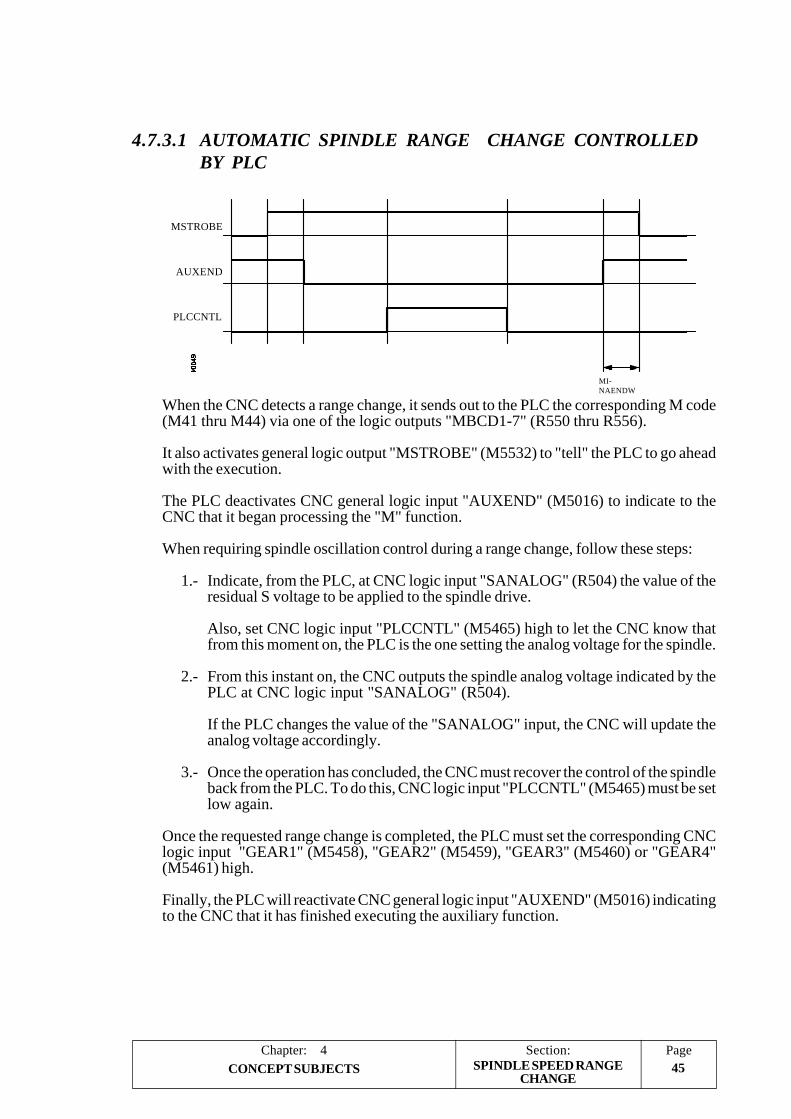
PageChapter: 4 Section:45CONCEPT SUBJECTS
AUXEND
MSTROBE
PLCCNTL
MI-NAENDW
4.7.3.1 AUTOMATIC SPINDLE RANGE CHANGE CONTROLLEDBY PLC
When the CNC detects a range change, it sends out to the PLC the corresponding M code(M41 thru M44) via one of the logic outputs "MBCD1-7" (R550 thru R556).
It also activates general logic output "MSTROBE" (M5532) to "tell" the PLC to go aheadwith the execution.
The PLC deactivates CNC general logic input "AUXEND" (M5016) to indicate to theCNC that it began processing the "M" function.
When requiring spindle oscillation control during a range change, follow these steps:
1.- Indicate, from the PLC, at CNC logic input "SANALOG" (R504) the value of theresidual S voltage to be applied to the spindle drive.
Also, set CNC logic input "PLCCNTL" (M5465) high to let the CNC know thatfrom this moment on, the PLC is the one setting the analog voltage for the spindle.
2.- From this instant on, the CNC outputs the spindle analog voltage indicated by thePLC at CNC logic input "SANALOG" (R504).
If the PLC changes the value of the "SANALOG" input, the CNC will update theanalog voltage accordingly.
3.- Once the operation has concluded, the CNC must recover the control of the spindleback from the PLC. To do this, CNC logic input "PLCCNTL" (M5465) must be setlow again.
Once the requested range change is completed, the PLC must set the corresponding CNClogic input "GEAR1" (M5458), "GEAR2" (M5459), "GEAR3" (M5460) or "GEAR4"(M5461) high.
Finally, the PLC will reactivate CNC general logic input "AUXEND" (M5016) indicatingto the CNC that it has finished executing the auxiliary function.
SPINDLE SPEED RANGECHANGE

Section:Chapter: 446
Page
CONCEPT SUBJECTS
4.7.3.2 AUTOMATIC SPINDLE RANGE CHANGE WHEN WORKINGWITH M19
Every time M19 is programmed, it is recommended that the corresponding spindle rangebe selected.
If no range is already selected, the CNC proceeds as follows:
- It converts the speed indicated in degrees per minute at machine parameter "REFEED1"(P34) into rpm.
- It selects the speed range corresponding to those rpm.
The spindle range cannot be changed when operating in M19. It must be selectedbeforehand.
SPINDLE SPEED RANGECHANGE

PageChapter: 4 Section:47CONCEPT SUBJECTS SPINDLE IN CLOSED LOOP
4.7.4 SPINDLE IN CLOSED LOOP
In order for the spindle to operate in closed loop by means of "spindle orientation (M19)",the following conditions must be met:
* The velocity command for the spindle must be analog (±10V). Spindle machineparameter "SPDLTYPE (P0) = 0".
* An encoder must be mounted onto the spindle. Spindle machine parameter "NPULSES"(P13) must indicated the number of square pulses supplied by the spindle encoder.
Also, when switching from open to closed loop, either an "M19" or an "M19 S±5.5" mustbe executed.
The S±5.5 code indicates the spindle position, in degrees, from the spindle reference point(marker pulse).
When switching form open to closed loop, the CNC behaves as follows:
* If the spindle has a home switch, it performs a home-switch search at the turning speedset by spindle machine parameter "REFEED1" (P34).
It then searches for actual marker pulse (Io) of the spindle encoder at the turning speedset by spindle machine parameter "REFEED2" (P35).
And, finally, it positions the spindle at the programmed S±5.5 point.
* If the spindle does not have a home switch, it searches the encoder marker pulse at theturning speed set by spindle machine parameter "REFEED2" (P35).
And, then, it positions the spindle at the programmed S±5.5 point.
4.7.4.1 CALCULATING SPINDLE RESOLUTION
The CNC assumes that one encoder revolution represents 360º. Therefore, the feedback(counting) resolution depends on the number of lines of the spindle encoder.
Resolution = 360° / (4 x number of encoder lines per revolution)
Hence, to obtain a resolution of 0.001º, a 90,000 line encoder is required and a 180,000 lineencoder to obtain a resolution of 0.0005º.
Spindle machine parameter "NPULSES" (P13) must indicate the number of square pulsessupplied by the spindle encoder.
In order to be able to use feedback alarm on the spindle encoder, "FBACKAL" (P15), thepulses provided by the encoder must be differential (double ended) squarewave "DIFFBACK(P14) = YES".

Section:Chapter: 448
Page
CONCEPT SUBJECTS SPINDLE IN CLOSED LOOP
4.7.4.2 GAIN SETTING
The various types of gains must be adjusted in order to optimize the system's performancefor the programmed movements.
An oscilloscope is highly recommended to make this critical adjustment by monitoring thetacho signals. The illustration below shows the optimum shape for this signal (on the left)and the instabilities to be avoided during start-up and brake down:
There are three types of gain. They are adjusted by means of machine parameters andfollowing the sequence indicated next.
Proportional Gain
It defines the analog output corresponding to a feedrate resulting in 1º of following error.
It is set by spindle machine parameter "PROGAIN" (P23)
Feed Forward Gain
It sets the percentage of analog output dependent of the programmed feedrate.
It must be set only when operating with acceleration / deceleration (spindle machineparameter "ACCTIME" (P18) ).
It is set by spindle machine parameter "FFGAIN" (P25)
Derivative Gain or AC-Forward Gain.
The "Derivative Gain" sets the percentage of analog output applied depending on thefluctuations of following error.
The "AC-Forward Gain" sets the percentage of analog output proportional to thefeedrate increments (acceleration and deceleration stages).
It must be used only when operating with acc. /dec. (spindle machine parameter"ACCTIME" (P18) ).
It is set by spindle machine parameters "DERGAIN" (P24) and "ACFGAIN" (P42).
With "ACFGAIN=No" it applies Derivative Gain.With "ACFGAIN=Yes" it applies AC-Forward Gain.

PageChapter: 4 Section:49CONCEPT SUBJECTS SPINDLE IN CLOSED LOOP
4.7.4.3 PROPORTIONAL GAIN SETTING
In a "pure" proportional positional loop, the analog output of the CNC to control the spindleis, at all times, proportional to the following error (axis lag) which is the difference betweenits theoretical and actual (real) position.
Analog output = Proportional Gain x Following Error
Spindle machine parameter "PROGAIN" (P23) sets the value of the Proportional Gain.Expressed in millivolts/degree, it takes any integer between 0 and 65535.
Its value indicates the analog output corresponding to a feedrate resulting in 1º of followingerror.
Example:
The maximum speed for the 1st range (rapid traverse G00) is 500 rpm and we wouldlike to obtain 1º at a speed of 1000 º/min. (2.778 rpm)
Drive analog: 9.5V for 500 rpm
Analog output corresponding to S = 1000 º/min. (2.778 rpm)
9.5 V.Analog = --------------- x 2.778 rpm = 52.778 mV
500 rpm
9.5 V.Analog = ---------------- x 1000 mm/min. = 0.633V = 633mV
15,000 mm/min.
Therefore, "PROGAIN" (P23) = 53
When setting the proportional gain, the following considerations must be taken intoaccount:
* The maximum amount of following error allowed by the CNC for the spindle is thevalue indicated by spindle machine parameter "MAXFLWE1" (P21). When exceeded,the CNC issues the corresponding following error message.
* The amount of following error decreases as the gain increases, but it tends to make thesystem unstable.
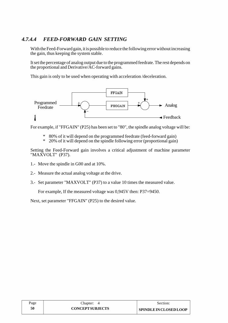
Section:Chapter: 450
Page
CONCEPT SUBJECTS
Analog
Feedback
ProgrammedFeedrate
4.7.4.4 FEED-FORWARD GAIN SETTING
With the Feed-Forward gain, it is possible to reduce the following error without increasingthe gain, thus keeping the system stable.
It set the percentage of analog output due to the programmed feedrate. The rest depends onthe proportional and Derivative/AC-forward gains.
This gain is only to be used when operating with acceleration /deceleration.
For example, if "FFGAIN" (P25) has been set to "80", the spindle analog voltage will be:
* 80% of it will depend on the programmed feedrate (feed-forward gain)* 20% of it will depend on the spindle following error (proportional gain)
Setting the Feed-Forward gain involves a critical adjustment of machine parameter"MAXVOLT" (P37).
1.- Move the spindle in G00 and at 10%.
2.- Measure the actual analog voltage at the drive.
3.- Set parameter "MAXVOLT" (P37) to a value 10 times the measured value.
For example, If the measured voltage was 0,945V then: P37=9450.
Next, set parameter "FFGAIN" (P25) to the desired value.
SPINDLE IN CLOSED LOOP

PageChapter: 4 Section:51CONCEPT SUBJECTS
AnalogProgrammedFeedrate
Feedback
Feedback
ProgrammedFeedrate
Analog
4.7.4.5 DERIVATIVE / AC-FORWARD GAIN SETTING
With the Derivative gain, it is possible to reduce the following error during the acc./dec.stages.
Its value is determined by spindle machine parameter "DERGAIN" (P24).
When this additional analog voltage is due to fluctuations of following error, "ACFGAIN"(P42) = NO, it is called: "Derivative Gain".
When it is due to variations of the programmed feedrate, "ACFGAIN" (P42) = YES, it iscalled AC-forward Gain" since it is due to acc./dec.
Best results are usually obtained when using it as AC-forward Gain, "ACFGAIN" (P42)= YES together with Feed-Forward Gain.
This gain is only to be used when operating with acceleration / deceleration.
A practical value between 2 to 3 times the Proportional Gain, "PROGAIN" (P23), may beused.
To perform a critical adjustment, proceed as follows:
* Verify that there is no oscillations on following error, In other words, that it is notunstable.
* Check, with an oscilloscope, the tacho voltage or the analog voltage at the drive (velocitycommand), verify that it is stable (left graph) and that there are neither instabilities whenstarting up (center graph) nor when braking down (right graph).
SPINDLE IN CLOSED LOOP

Section:Chapter: 452
Page
CONCEPT SUBJECTS SPINDLE IN CLOSED LOOP
4.7.4.6 MACHINE REFERENCE SETTING
To set the machine reference point proceed as follows:
* Indicate in spindle machine parameter "REFPULSE" (P32) the type of marker pulse(Io) used by the feedback device.
* Also, indicate in spindle machine parameter "REFDIREC" (P33) the homing directionto look for that marker pulse.
* Set the spindle machine parameters defining the home switch approaching feedrate"REFEED1" (P34), and the marker pulse searching feedrate after the home switch hasbeen found "REFEED2" (P35).
* The machine reference point will be set to "0". Spindle machine parameter"REFVALUE" (P36).
* Once in the JOG mode and after positioning the spindle in the right area, start homingthe spindle. When done, the CNC will assign a "0" value to this point.
* After moving the spindle to the Machine Reference Zero or up to a known position(with respect to Machine Reference Zero), observe the position reading of the CNC forthat point.
This will be distance from the Machine Reference Zero to that point. Therefore, thevalue to be assigned to spindle machine parameter "REFVALUE" (P36), whichdefines the coordinate corresponding to the Machine Reference Point (physicallocation of the marker pulse).
"REFVALUE" P36 = Machine Coordinate of the point - CNC reading at that point
Example: If the point whose known position is located 230 mm from MachineReference Zero and the CNC reads -123.5º as the coordinate value for thispoint, the coordinate of the Machine Reference Point with respect toMachine Reference Zero will be:
"REFVALUE" P36 = 12 - (-123.5) = 135.5º
* After allocating this new value to the machine parameter, press SHIFT + RESET orturn the CNC off and back on in order for this value to be assumed by the CNC.
* The spindle must be homed again in order for it to assume its right reference values.

PageChapter: 4 Section:53CONCEPT SUBJECTS SPINDLE IN CLOSED LOOP
REFEED 1
REFEED 2
Marker pulse (home)Home switch
4.7.4.7 CONSIDERATIONS
* If at the time when the home search is requested, the spindle is sitting on the homeswitch, the spindle will back up (in the direction opposite to the one indicated by“REFDIREC (P33) ”) until it is off the switch and then, it will go on to searching home.
* Care must be taken when placing the home switch and when setting feedrates“REFEED1 (P34)” and “REFEED2 (P35)”.
The home switch will be installed so the marker pulse will be found in the zonecorresponding to feedrate “REFEED2 (P35)”.
If there is no room for it, reduce the value of “REFEED1 (P34)”. For example, for encoderswhose consecutive marker pulses are very close to each other.
* When the selected spindle does not have a machine reference (home) switch (spindlemachine parameter “DECINPUT (P31)” = NO), the CNC will move the spindle at thefeedrate set by spindle machine parameter “REFEED2 (P35)” until the first markerpulse from the current position is found, thus ending the home search.
* FAGOR rotary encoders provide one positive reference pulse per revolution.
* Do not mistake the type of reference pulse being used (positive or negative) with thetype of active flank (up or down) to be used when setting spindle machine parameter“REFPULSE (P32)”.

Section:Chapter: 454
Page
CONCEPT SUBJECTS
4.8 TREATMENT OF EMERGENCY SIGNALS
4.8.1 EMERGENCY SIGNALS
The FAGOR 8050 CNC provides the following emergency signals:
/EMERGENCY STOP Physical emergency input.
It is generated from the outside and it corresponds to pin 2 of connector X9.
This signal is active low (0V).
/EMERGENCY OUTPUT Physical emergency output.
It is generated internally when an error is detEcted at the CNC or at the PLC.
This signal is active low (0 V).
/EMERGEN (M5000) Logic input of the CNC, generated by the PLC.
When the PLC activates this signal, the CNC stops the axes feed and the rotation ofthe spindle and it displays the corresponding error message.
This signal is active low (0 V).
/ALARM (M5507) Logic input of the PLC, generated by the CNC.
The CNC activates this signal to let the PLC “know” that an alarm or emergencycondition has occurred.
This signal is active low (0 V).
TREATMENT OFEMERGENCY SIGNALS

PageChapter: 4 Section:55CONCEPT SUBJECTS
4.8.2 CNC TREATMENT OF EMERGENCY SIGNALS
The emergency inputs of the CNC are:
/EMERGENCY STOP Physical input coming from the outside./EMERGEN (M5000) Physical input coming from the PLC.
The emergency outputs of the CNC are:
/EMERGENCY OUTPUT Physical output to the outside./ALARM (M5507) Physical output to the PLC.
There are to ways to cause an emergency at the CNC, by activating the physical input/EMERGENCY STOP or the general logic input “/EMERGEN” from the PLC.
Whenever any of these signals is activated, the CNC stops the axes feed and the spindlerotation and it displays the corresponding error message.
By the same token, when the CNC detects an internal malfunction or at an externaldevice, it stops the axes feed and the spindle rotation displaying at the same time thecorresponding error message.
In both cases, the CNC will activate the /EMERGENCY OUTPUT and /ALARMsignals to indicate to the PLC and to the outside world that an emergency has occurredat the CNC.
Once the cause of the emergency has disappeared, the CNC will deactivate these signalsto indicate to the PLC and to the outside world that everything is back to normal.
TREATMENT OFEMERGENCY SIGNALS

Section:Chapter: 456
Page
CONCEPT SUBJECTS
4.8.3 PLC TREATMENT OF EMERGENCY SIGNALS
The emergency inputs of the PLC are:
/EMERGENCY STOP Physical input coming from the outside./ALARM (M5507) Physical input coming from the CNC.
The emergency outputs of the PLC are:
/EMERGENCY OUTPUT Physical output to the outside./EMERGEN (M5000) Physical output to the CNC.
There are two ways to “tell” the PLC that an emergency condition must be treated, byactivating the physical input EMERGENCY STOP of the PLC (which is I1) or thegeneral logic input “/ALARM” of the PLC which is mark M5507.
In both cases, the treatment of these signals will be up to the PLC programmer. The PLCprogram must have the necessary instructions to properly attend to these emergencyinputs and act accordingly.
By the same token, the PLC program must have the necessary instructions to properlyactivate the emergency outputs when required.
These emergency signals are the physical output /EMERGENCY OUTPUT (output O1of the PLC) and the general logic output /EMERGEN” which is mark M5000 of thePLC.
It must be born in mind that every time a new PLC program cycle is initiated, the realinputs are updated with the physical inputs. Therefore, input I1 will have the value of thephysical input /EMERGENCY STOP.
Also, before executing the PLC program cycle, the values of the M and R resourcescorresponding to the CNC logic outputs (internal variables) are updated as well as markM5507 corresponding to the /ALARM signal.
After the execution of each cycle, the PLC updates the physical outputs with the valuesof the real outputs except the physical output /EMERGENCY OUTPUT which will beactivated whenever the real output O1 or mark M5507 (/ALARM signal coming fromthe CNC) is active.

PageChapter: 5 Section:1INTRODUCTION TO THE PLC
5. INTRODUCTION TO THE PLC
It is highly recommended to save the machine parameters in a peripheral device or computerin order to avoid losing them by replacing modules, checksum errors, operator errors, etc.
The PLC program can be introduced from the front panel or from a computer or peripheral,using the RS232C and RS422 serial lines.
The PLC program will be stored in the internal memory of the CNC together with the partprograms and are displayed in the program directory (utilities) together with the partprograms.
Once the program has been compiled, the PLC will generate the executable code which willbe stored in the PLC’s internal memory.
The CNC has an EEPROM to store the PLC program and the User customized pages(screens).
On CNC power-up, the PLC will execute the Object Program. If this program does notexist, it will be generated by compiling the Source Program "PLC_PRG", if it exists, or theone saved in the EEPROM otherwise. Once the Object Program is generated, the PLC willexecute it.
Should there be no source program, the CNC will issue the corresponding error message.
Yes
No
No
Yes
Yes
No
RUN
Generate Object Program
Error Message
EEPROMProgram
Source Program"PLC-PRG"
ObjectProgram

Section:Chapter: 52
Page
INTRODUCTION TO THE PLC
The PLC has 256 inputs and 256 outputs, some of which, depending on the configurationof the CNC acquired can communicate with the outside. The numbering of inputs andoutputs for each of the modules will be as follows:
AXES module I1 -I40 O1 -O24INPUT/OUTPUT Module (1) I65 -I128 O33-O64INPUT/OUTPUT Module (2) I129-I192 O65-O96INPUT/OUTPUT Module (3) I193-I256 O97-O128
There is an exchange of information between the CNC and the PLC which is doneautomatically and the system has a series of commands which allow the following to bedone quickly and simply:
* The control of Logic CNC inputs and outputs by means of an exchange ofinformation between both systems.
* The transfer from the CNC to the PLC of M, S, T auxiliary functions.
* To display a screen previously defined by the user, as well as generating messagesand errors in the CNC.
* The reading and modification of internal CNC variables from the PLC.
* Access to all PLC variables from any part program.
* Monitoring of PLC variables on the CNC screen.
* Access to all PLC variables from a computer, via DNC and by means of the RS232 C and RS 422 serial ports.

PageChapter: 5 Section:3INTRODUCTION TO THE PLC
5.1 PLC RESOURCES
INPUTS (I): These are elements which supply information to the PLC from signalsreceived from the outside world. They are represented by the letter I and there are 256inputs available.
OUTPUTS (O): These are elements which allow the PLC to activate or deactivate thedifferent devices in the electrical cabinet. These are represented by the letter O andthere are 256 outputs available.
MARKS (M): These are elements capable of memorizing in one bit (as if it were an internalrelay) the status of the different internal variables of the CNC (information of the logicoutputs received in the communication between the CNC and the PLC of the CNC)and the status of the different variables of the PLC, whether these are internal orestablished by the user. They are represented by the letter M, and there are 2000 usermarks and other special marks.
REGISTERS (R): These are elements which allow a numerical value to be stored in 32bits or facilitate CNC-PLC communication with the Logic CNC inputs-outputs.They are represented by the letter R and there are 256 user registers and other specialregisters.
TIMERS (T): These are elements which, once activated, alter the status of their output fora specific time (time constant). They are represented by the letter T, and there are 256timers.
COUNTERS (C): These are elements capable of counting up or down a specific amountof events. They are represented by the letter C and there are 256 counters.
VARIABLES

Section:Chapter: 54
Page
INTRODUCTION TO THE PLC PROGRAM EXECUTION
5.2 PLC PROGRAM EXECUTION
The PLC executes the user program cyclically. In other words, once it executes the completeprogram, it re-starts running this program from the first instruction.
This cyclic processing of the program is done as follows:
1. It allocates the current values of physical CNC inputs (AXES and I/O moduleconnectors) to the "I" resources of the PLC.
For instance, if physical input I10 (pin 25 of connector X9 of the Axes module) isreceiving 24 V, the PLC sets resource "I10" to "1".
Only the inputs corresponding to the modules being used are updated. This way, whenhaving the axes module and one I/O module, the PLC will only update resources I1thru I40 and I65 thru I128. The rest of the "I" resources will not be modified.
2. It allocates the current values of the logic CNC outputs (CNCREADY, START,FHOUT, .....) to PLC resources M5500 thru M5957 and R550 thru R562 .
3. It runs the program cycle.
The next section of this chapter describes the structure of the PLC program and itsexecution modules.
Modules:Axes + I/O
Phy
sica
l Out
puts
Phy
sica
l Inp
uts
REAL MEMORY
Inputs
Outputs
Logic CNCInputs and Outputs
of Cycle
Beginning
Beginning
of Cycle

PageChapter: 5 Section:5INTRODUCTION TO THE PLC PROGRAM EXECUTION
4. It updates the Logic CNC inputs (/EMERGEN, /STOP, /FEEDHOL, ...) with thecurrent values of PLC resources M5000 thru M5465 and R500 thru R505.
5. Allocates the current values of PLC "O" resources to the physical outputs (connectorsof the Axes and I/O modules).
For instance, if resource "O5" is set to "1", the PLC sets physical output "O5" (pin 4of connector X10 of the Axes module) to 24V.
6. Bear in mind that all the actions of the program executed by the PLC alter the status ofits resources.
Example: I10 AND I20 = O5
When this condition is met [resource I10 is "1" and I20 is also "1"], the PLC setsresource "O5" to "1". If this condition is not met, the PLC sets resource "O5" to "0".
Therefore, the status of a resource may change during the execution of the PLCprogram.
Example, assuming that the initial status of resource M100 is "0":
M100 AND I7 = O3 M100 = "0"I10 = M100 M100 takes the value of resource I10M100 AND I8 = M101 The value of M100 depends on the previous instruction.
This type of problems may be prevented by careful programming or by using "Image"resource values (instead of "Real" values).
Modules:Axes + I/O
REAL MEMORY
Inputs
Outputs
Logic CNCInputs and Outputs
Phy
sica
l Out
puts
Phy
sica
l Inp
uts
Cycle
End of
End of
Cycle

Section:Chapter: 56
Page
INTRODUCTION TO THE PLC PROGRAM EXECUTION
The PLC has 2 memories to store the status of the various registers: Real and Image.
All the steps described so far work with Real memory.Saying "the value of such and such register" is the same as saying "the Real value ofsuch and such register".
The Image Memory contains a copy of the values (status) that the resources had at theend of the previous cycle.
The PLC makes this copy at the end of the cycle.
The resources having an image value are: I1 thru I256, O1 thru O256 and M1 thruM2047
The next example shows how the PLC acts when operating with real and image values.
Logic CNCInputs and Outputs
Modules:Axes + I/O
REAL MEMORYOutputs
Inputs
Phy
sica
l Out
puts
Phy
sica
l Inp
uts
IMAGE MEMORY
End ofCycle
End ofCycle
End ofCycle

PageChapter: 5 Section:7INTRODUCTION TO THE PLC PROGRAM EXECUTION
The first program line indicates that resource M1 is set to "1".
Operating with real values:
M1 = M2 The real value of M1 is "1", it has been set by the previous line.M2 = M3 The real value of M2 is "1", it has been set by the previous line.M3 = O5 The real value of M3 is "1", it has been set by the previous line.
Operating with image values:
The first cycle (scan) sets the real value of M1=1; but its image value will not be setto "1" until the end of the cycle.
In the 2nd cycle (scan), the image value of M1 is "1" and the real value of M2 is setto "1".But the image value of M2 will not be set to "1" until the end of the cycle.
In the 3rd cycle (scan), the image value of M2 is "1" and the real value of M3 is setto "1".But the image value of M3 will not be set to "1" until the end of the cycle.
In the 4th cycle (scan), the image value of M3 is "1" and the real value of O5 is setto "1".
As can be observed, the system is faster when operating with real resource values.
Operating with image values permits analyzing the same resource along the wholeprogram with the same value regardless of its current (instantaneous) real value.
7. It concludes this cycle scan and it gets ready for the next one.
The flow-chart on the next page illustrates the cyclic program processing.
Using Real values Using Image values
PLC Program M1 M2 M3 O5 M1 M2 M3 O5
() = M1 Initial status 0 0 0 0 0 0 0 0
M1 = M2 End of 1st Scan 1 1 1 1 1 0 0 0
M2 = M3 End of 2nd Scan 1 1 1 1 1 1 0 0
M3 = O1 End of 3rd Scan 1 1 1 1 1 1 1 0
End of 4th Scan 1 1 1 1 1 1 1 1

Section:Chapter: 58
Page
INTRODUCTION TO THE PLC PROGRAM EXECUTION
Cyclic program processing
Physical I Real I
Logic CNCOutputs
Yes 1st time &there is
CY1
Real O Physical O
Logic CNC Inputs
Real Values Image Values

PageChapter: 5 Section:9INTRODUCTION TO THE PLC PROGRAM EXECUTION
Information exchange:
REAL MEMORYOutputs
Inputs
Phy
sica
l Out
puts
Phy
sica
l Inp
uts
IMAGE MEMORY
End ofCycle
End ofCycle
End ofCycle
Logic CNCInputs and Outputs
Modules:Axes + I/O
Beginning
Beginning
of Cycle
of Cycle
End of
Cycle
End of
Cycle

Section:Chapter: 510
Page
INTRODUCTION TO THE PLC
i + 1 i + 2 i + 3
Cycle i i + 1 i + 2 i + 3
WDGPRG
CYCLETIME
Cycle i
CYCLETIME
WATCH-DOGError
PROGRAM EXECUTION
The time the PLC requires to execute the program is called cycle time and can vary in thesuccessive cycles of a same program, as the conditions under which they are executed arenot the same.
By means of the PLC machine parameter “WDGPRG” a maximum cycle execution timeis established. This is called WATCH-DOG time and if a cycle is executed which lastslonger than 1.5 times this time, or two cycles are executed, one after the other, taking longerthan this time period, the CNC will display the WATCH-DOG error of the Main Module.
This way, the execution of cycles that, due to their duration, disturb the operation of themachine can be prevented and the PLC can be prevented from executing a cycle which hasno end due to a programming error.

PageChapter: 5 Section:11INTRODUCTION TO THE PLC
5.3 MODULAR PROGRAM STRUCTURE
The program to be executed by the PLC consists of a series of MODULES which areappropriately defined by means of DIRECTING INSTRUCTIONS.
The modules which can make up the program are:
Main module (PRG)Periodic execution module (PE)First cycle module (CY1)
Each module must begin with the directing instruction which defines it (PRG, PE, CY1)and end with the directing instruction END.
Should the main program contain the MAIN MODULE only it is not necessary to placethe instructions PRG and END.
5.3.1 FIRST CYCLE MODULE (CY1)
This module is optional and will only be executed whenthe PLC is turned on. It is used to initialize the differentresources and variables with their initial values, beforeproceeding to execute the rest of the program.
This module operates by default with the real values ofresources I, O, M.
It is not necessary for this to be at the beginning of theprogram, but must always be preceded by the instructionCY1.
5.3.2 MAIN MODULE (PRG)
This module contains the user program. It will be executedcyclically and will be given the task of analyzing andmodifying CNC inputs and outputs. Its time of executionwill be limited by the value indicated in the PLC machineparameter “WDGPRG”.
This module operates by default with the image values ofresources I, O, M.
There can only be one main program and this must bepreceded by the instruction PRG, it is not necessary todefine it if it starts on the first line.
CY1
END
PRG
END
MODULAR STRUCTURE

Section:Chapter: 512
Page
INTRODUCTION TO THE PLC
5.3.3 PERIODIC EXECUTION MODULE (PE t)
This module is optional and will be executed every period of timet indicated in the directing instruction defining the module.
This module may be used to process certain critical inputs andoutputs which cannot be checked or updated properly in the bodyof the main program due to its extended execution time.
Another application for this module is for those cases where specific tasks need not beevaluated at every PLC program cycle. Those tasks would be programmed in the periodicmodule and they would be executed with the frequency established by the execution timeassigned to this module (for example: if t= 30,000; every 30 seconds).
A t value of between 1 and 65535 milliseconds can be programmed and the execution timeof this module will be limited by the value indicated in the PLC machine parameter“WDGPER”.
This module operates by default with the real values of resources I, O, M.
Example:
PE 10 Defines the beginning of the Periodic Module PE which will beexecuted every 10 milliseconds.
If this module is being executed with real values and acts on a physical output, this is updatedat the end of the execution of the periodic module.
MODULAR STRUCTURE
PE t
END

PageChapter: 5 Section:13INTRODUCTION TO THE PLC
CY1
END
PRG
END
CY1
PEt
PRG
t tt t t
5.3.4 PRIORITY IN THE EXECUTION OF PLC MODULES
Every time the PLC program is started (command RUN) the first module to be executedis the first cycle Module (CY1). Once execution has been completed, it will continue withthe main Module (PRG).
The main Module will be executed cyclically until the execution of the PLC has stopped(command STOP).
The Periodic Module will be executed every time the time indicated in the directinginstruction “PE t” elapses. This count starts when the execution of the Main Module (thefirst time) begins.
Every time this module is executed, the execution of the Main Module is interrupted, andits execution resumes when the execution of the Periodic Module finishes.
PRIORITIES

PageChapter: 6 Section:1PLC RESOURCES
6. PLC RESOURCES
6.1 INPUTS
These are elements which provide the PLC with information from the signals which arereceived from the outside world. They are represented by the letter I followed by the inputnumber which is desired to reference, for example I1, I25, I102, etc.
The PLC may control 256 inputs although when communicating with the outside worldit can only access the ones indicated by each module.
The numbering of the inputs at each module is determined by the logic address (deviceselect code) assigned to the module in such a way that the first group of inputs correspondsto the module with the lowest device select code and the last group of inputs correspondsto the module with the highest select code. For example:
Module Device Select Code Inputs
AXES 2 I1 -I40I/O TRACING 3 I65 -I128INPUT/OUTPUT (1) 4 I129-I192INPUT/OUTPUT (2) 5 I193-I256
6.2 OUTPUTS
These are elements which allow the PLC to activate or deactivate the different devices ordrives in the electrical cabinet. They are represented by the letter O followed by the outputnumber which is desired to reference, for example O1, O25, O102, etc.
The PLC may control 256 outputs although when communicating with the outside worldit can only access the ones indicated by each module.
The numbering of the outputs at each module is determined by the logic address (deviceselect code) assigned to the module in such a way that the first group of outputs correspondsto the module with the lowest device select code and the last group of outputs correspondsto the module with the highest select code. For example:
Module Device Select Code Outputs
AXES 2 O1 -O24I/O TRACING 3 O33 -O64INPUT/OUTPUT (1) 4 O65-O96INPUT/OUTPUT (2) 5 O97-O128
Output O1 coincides with the emergency output of the CNC (pin 2 of connector X10); thus,it must be kept high (logic level 1).
INPUTS AND OUTPUTS

Section:Chapter: 62
Page
PLC RESOURCES
6.3 MARKS
These are elements capable of memorizing in one bit (as if they were an internal relay)information defined by the user, their value being inalterable even when the power supplyto the system is turned off.
This will be programmed by the letter M followed by the number of the mark which it iswished to reference, for example, M1, M25, M102, etc.
The PLC controls the following marks:
User marks M1 - M2000Arithmetic flag marks M2001Clock marks M2009 - M2024Fixed status marks M2046 & M2047Marks associated with messages M4000 - M4127Marks associated with errors M4500 - M4563Screen marks M4700 - M4955CNC communication marks M5000 - M5957
Marks M1 thru M2047 have image values unlike the remainder of the marks, and so thePLC will always work with their real values.
The arithmetic flag mark available at the PLC is:
M2003 Is the Zero flag and is set to 1 (high logic level) when the result of an AND,OR, XOR operation is 0.
The clock marks M2009 to M2024, make up internal clocks of different periods which canbe used by the user.
MARK Half Period
M2009 100 msec.M2010 200 msec.M2011 400 msec.M2012 800 msec.M2013 1.6 sec.M2014 3.2 sec.M2015 6.4 sec.M2016 12.8 sec.M2017 1 sec.M2018 2 sec.M2019 4 sec.M2020 8 sec.M2021 16 sec.M2022 32 sec.M2023 64 sec.M2024 128 sec.
MARKS

PageChapter: 6 Section:3PLC RESOURCES
The fixed status marks available at the PLC are:
M2046 Always has a value of 0.M2047 Always has a value of 1.
The PLC allows, by means of the activation of a series of message marks, the PLC messagecorresponding to the PLC message table to be displayed on the CNC screen. They can benamed by means of the mark M4000 - M4127 or by means of their associated mnemonicMSG1 - MSG128:
M4000 MSG1M4001 MSG2..... .......... .....M4126 MSG127M4127 MSG128
Likewise, 64 error marks are available which allow the error corresponding to the PLC errortable to be displayed on the CNC screen as well as to interrupt the execution of the CNCprogram, stopping axis feed and spindle rotation. The activation of one of these marks doesnot activate the CNC external Emergency output.
They can be named by means of mark M4500-M4563 or by means of their associatedmnemonic ERR1 - ERR64:
M4500 ERR1M4501 ERR2..... .......... .....M4562 ERR63M4563 ERR64
It is recommended to change the status of these marks by means of accessible external inputssince the PLC will not stop and the CNC will receive the error message in each new PLCcycle scan; thus preventing access to any of the PLC modes.
By activating one of the marks M4700-M4955 user pages 0-255 can be activated in theCNC. They can be named by means of mark M4700-M4955 or by means of their associatedmnemonic PIC0 - PIC255:
M4700 PIC0M4701 PIC1..... .......... .....M4954 PIC254M4955 PIC255
The PLC has marks M5000 to M5957 to exchange information with the CNC, all of whichhave associated mnemonics and are detailed in the chapter which deals with CNC - PLCcommunication.
MARKS

Section:Chapter: 64
Page
PLC RESOURCES
6.4 REGISTERS
These are elements which store a numerical value in 32 bits, their value remainingunalterable even when the power supply to the system is cut off.
They do not have image values and are represented by the letter R, followed by the registernumber it is desired to reference, for example R1, R25, R102, etc.
The PLC has the following registers:
User registers R1 - R256Registers for communication with the CNC R500 - R559
The PLC will consider each value stored in each register as an integer with a sign, and canbe within ±2147483647.
It is also possible to make reference to a BIT of the REGISTER by putting the letter B andthe bit number (0/31) in front of the selected register. For example:
B7 R155 Refers to Bit 7 of Register 155.
The PLC considers bit 0 as being the one with least significance and bit 31 as being the onewith most significance.
The value stored iN a Register can be treated as being decimal, hexadecimal (preceded by“$”), binary (preceded by “B”) or in BCD.
Example:
Decimal : 156Hexadecimal : $9CBinary : B0000 0000 0000 0000 0000 0000 1001 1100
REGISTERS

PageChapter: 6 Section:5PLC RESOURCES
6.5 TIMERS
These are elements capable of maintaining their output at a determined logic level duringa preset time (time constant), after which the output changes status.
They do not have image values and are represented by the letter T, followed by the numberof the timer it is required to reference, for example, T1, T25, T102, etc.
The time constant is stored in a 32-bit variable, and so its value can be between 0 and4294967295 milliseconds, which is equivalent to 1193 hours (almost 50 days).
The PLC has 256 timers, each of which has T status output and TEN, TRS, TG1, TG2,TG3 and TG4 inputs. It is also possible to consult at any moment the time which has elapsedfrom the moment it was activated.
ENABLE INPUT (TEN)
This input allows the timing of the timer to be stopped. It is referred to by the letter TENfollowed by the number of the timer which is wished to reference, for example TEN 1, TEN25, TEN 102, etc.
So that the time elapses within the timer this input must be at level “1”. By default every timea timer is activated the PLC will assign this input a logic level “1”.
If, once the timer has been activated, TEN = 0 is selected, the PLC stops the timing, it beingnecessary to assign TEN = 1 for this timing to continue.
Example:
I2 = TEN 10; Input I2 controls the Enable input of timer T10.
T 1/256
TEN
TRS
T
tTG 1
TG 4
..
TEN
t
TIMERS

Section:Chapter: 66
Page
PLC RESOURCES
RESET INPUT (TRS)
This input allows the timer to be initialized, by assigning the value 0 to its T status and bycancelling its count (it initializes this to 0). It is referred to by the letters TRS followed bythe timer number it is wished to reference, for example TRS 1, TRS 25, TRS 102, etc.
This initialization of the timer will be made when a transition of logic level from “0” to “1”(leading edge) is produced. By default and every time a timer is activated the PLC willassign this input a logic level of “0”.
If, once the timer is activated, a leading edge is produced at the TRS input, the PLCinitializes the timer, assigning value 0 to its T status and cancelling the count (it initializesthis to 0). Additionally, the timer is deactivated it being necessary to activate its trigger inputto activate it again.Example:
I3 = TRS 10 ; Input I3 controls the Reset input of timer T10.
TRIGGER INPUT (TG1, TG2, TG3, TG4)
These inputs allow the timer to be activated, and it begins to time. They are referred to bythe letters TG1, TG2, TG3, TG4 followed by the number of the timer it is required toreference and the value which is required to start the count with (Time Constant).
For example TG1 1 100, TG2 25 224, TG3 102 0, TG4 200 500, etc.
The Time Constant value is defined in thousandths of a second, and it is possible to indicatethis by means of a numerical value or by assigning it the internal value of an R register.
TG1 20 100 ; Activates timer T20 by means of trigger input TG1 and with atime constant of 100 milliseconds.
TG2 22 R200 ; Activates timer T22 by means of trigger input TG2 and with atime constant which will be defined (in thousandths of asecond) by the value of Register R200 when the instruction isexecuted.
TRS
t
TIMERS

PageChapter: 6 Section:7PLC RESOURCES
Inputs TG1, TG2, TG3 and TG4 are used to activate the timer in four different operatingmodes:
Input TG1 activates the timer in the MONOSTABLE mode.Input TG2 activates the timer in the ACTIVATION DELAY mode.Input TG3 activates the timer in the DEACTIVATION DELAY mode.Input TG4 activates the timer in the SIGNAL LIMITER mode.
This activation of the timer is made when a logic level transition of any of these inputs isproduced, either from “0” to “1” or from “1” to “0” (leading or trailing edge) depending onthe chosen input. By default and every time the timer is initialized by means of the RESETinput (TRS), the PLC will assign logic level “0” to these inputs.
The operating mode of each of these trigger inputs is explained individually.
STATUS OUTPUT (T)
This output indicates the logic status of the timer. It is referred to by the letter T followedby the number of the timer which it is required to reference, for example T1, T25, T102,etc.
The logic status of the timer depends on the operating mode selected by means of the triggerinputs TG1, TG2, TG3 and TG4, and so the activation or deactivation of this signal isexplained in each of the PLC operating modes.
ELAPSED TIME (T)
This output indicates the time elapsed in the timer since the moment it was activated. It isreferred to by the letter T followed by the number of the timer which it is required toreference, for example T1, T25, T102, etc.
Although when written as T123 it coincides with the Status Output, both are different andthey are also used in different types of instruction.
In binary type instructions, function T123 makes reference to the logic status of the timer.
T123 = M100 ; Assigns mark to M100 the status (0/1) of Timer 123
In arithmetic and comparison functions T123 makes reference to the time elapsed in thetimer from the moment it was activated.
I2 = MOV T123 R200 ; Transfers the time of T123 to register R200
CPS T123 GT 1000 = M100 ; Compares whether the time of T123 is greaterthan 1000, in which case it activates markM100.
The PLC has a 32-bit variable to store the time of each timer.
TIMERS
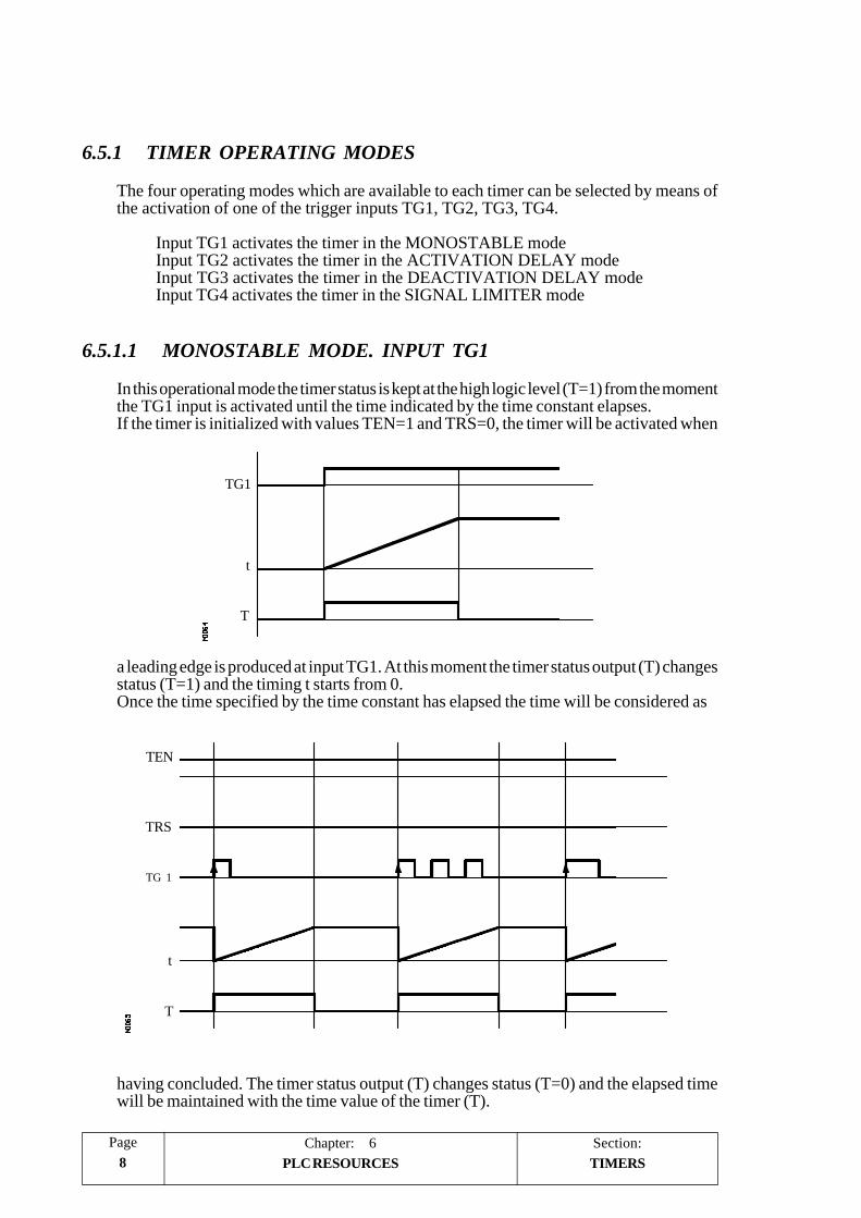
Section:Chapter: 68
Page
PLC RESOURCES
6.5.1 TIMER OPERATING MODES
The four operating modes which are available to each timer can be selected by means ofthe activation of one of the trigger inputs TG1, TG2, TG3, TG4.
Input TG1 activates the timer in the MONOSTABLE modeInput TG2 activates the timer in the ACTIVATION DELAY modeInput TG3 activates the timer in the DEACTIVATION DELAY modeInput TG4 activates the timer in the SIGNAL LIMITER mode
6.5.1.1 MONOSTABLE MODE. INPUT TG1
In this operational mode the timer status is kept at the high logic level (T=1) from the momentthe TG1 input is activated until the time indicated by the time constant elapses.If the timer is initialized with values TEN=1 and TRS=0, the timer will be activated when
a leading edge is produced at input TG1. At this moment the timer status output (T) changesstatus (T=1) and the timing t starts from 0.Once the time specified by the time constant has elapsed the time will be considered as
having concluded. The timer status output (T) changes status (T=0) and the elapsed timewill be maintained with the time value of the timer (T).
t
TG1
T
TEN
t
T
TRS
TG 1
TIMERS

PageChapter: 6 Section:9PLC RESOURCES
Any alteration which may be produced in input TG1 (leading or trailing edge) during thetiming operation will have no effect whatsoever.
If, once the timing is complete it is required to activate the timer again, another leading edgemust be produced at the TG1 input.
Operation of the TRS input in this mode
If a leading edge is produced at the TRS input at any moment during the timing orafterwards, the PLC initializes the timer, assigning the value 0 to its T status and cancellingits count (it initializes it to 0). Due to the fact that the timer is initialized, it will be necessaryto activate its trigger input to activate it again.
Operation of the TEN input in this mode
If, once the timer is activated, TEN = 0 is selected, the PLC stops timing, and it is necessaryto assign TEN = 1 for this timing to continue.
TRS
TG1
TEN
t
T
TRS
TG1
TEN
t
T
TIMERS

Section:Chapter: 610
Page
PLC RESOURCES
6.5.1.2 ACTIVATION DELAY MODE. INPUT TG2
This operating mode allows a delay to be made between the activation of the trigger inputTG2 and the activation of the T status of the timer.
The duration of the delay is determined by the time constant.
If the timer is initialized with values TEN=1 and TRS=0, the timer will be activated whena leading edge is produced at TG2 input. At that moment, timing t will start from a valueof 0.
Once the time specified by the time constant has elapsed the timing operation will beconsidered as having completed and the timer status output (T=1) will be activated and willremain in this status until the trailing edge is produced in the trigger input TG2.
The elapsed time will remain as a timer time value (T) once timing has been completed.If, once the timing has finished, it is required to activate the timer again, another leading edgemust be produced in the TG2 input.
If the trailing edge of the trigger input TG2 is produced before the time specified by the timeconstant has elapsed, the PLC will consider that the timing operation has concluded,maintaining the time count it had at that moment as the timer time (T).
TG2
t
T
TRS
TG2
TEN
t
T
TIMERS

PageChapter: 6 Section:11PLC RESOURCES
Operation of the TRS input in this mode
If a leading edge is produced in the TRS input at any moment during timing or afterwards,the PLC initializes the timer, assigning the value 0 to its T status and cancelling its count(it initializes this to 0). Due to the fact that the timer is initialized, it will be necessary toactivate its trigger input to activate it again.
Operation of the TEN input in this mode
If, once the timer is activated, TEN = 0 is selected, the PLC stops timing, and it is necessaryto assign TEN = 1 for this timing to continue.
TRS
TG2
TEN
t
T
TRS
TG2
TEN
t
T
TIMERS

Section:Chapter: 612
Page
PLC RESOURCES
6.5.1.3 DEACTIVATION DELAY MODE. INPUT TG3
This operating mode allows a delay to be made between the deactivation of the trigger inputTG3 and the activation of the T status of the timer.
The duration of the delay is determined by the time constant.
If the timer is initialized with values TEN=1 and TRS=0, the timer will be activated whena leading edge is produced at the TG3 input. At that moment, the timer status output willhave a value of T=1.
The timer will wait a trailing edge of the TG3 input to start timing t from a value of 0.
Once the time specified by the time constant has elapsed the timing operation will beconsidered as having completed and the timer status output will be deactivated (T=0).
The elapsed time will remain as a timer time value (T) once timing has been completed.
If, once the timing has finished, it is required to activate the timer again, another leading edgemust be produced at the TG3 input.
If another leading edge of the trigger input TG3 is produced before the time specified bythe time constant has elapsed, the PLC will consider that the timer has been activated again,maintaining its status (T=1) and initializing timing at 0.
TG3
t
T
TIMERS
TRS
TG3
TEN
t
T
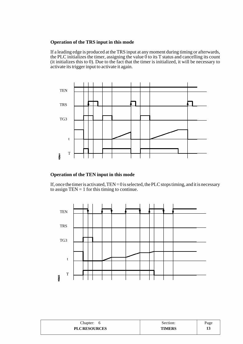
PageChapter: 6 Section:13PLC RESOURCES
Operation of the TRS input in this mode
If a leading edge is produced at the TRS input at any moment during timing or afterwards,the PLC initializes the timer, assigning the value 0 to its T status and cancelling its count(it initializes this to 0). Due to the fact that the timer is initialized, it will be necessary toactivate its trigger input to activate it again.
Operation of the TEN input in this mode
If, once the timer is activated, TEN = 0 is selected, the PLC stops timing, and it is necessaryto assign TEN = 1 for this timing to continue.
TRS
TG3
TEN
t
T
TRS
TG3
TEN
t
T
TIMERS
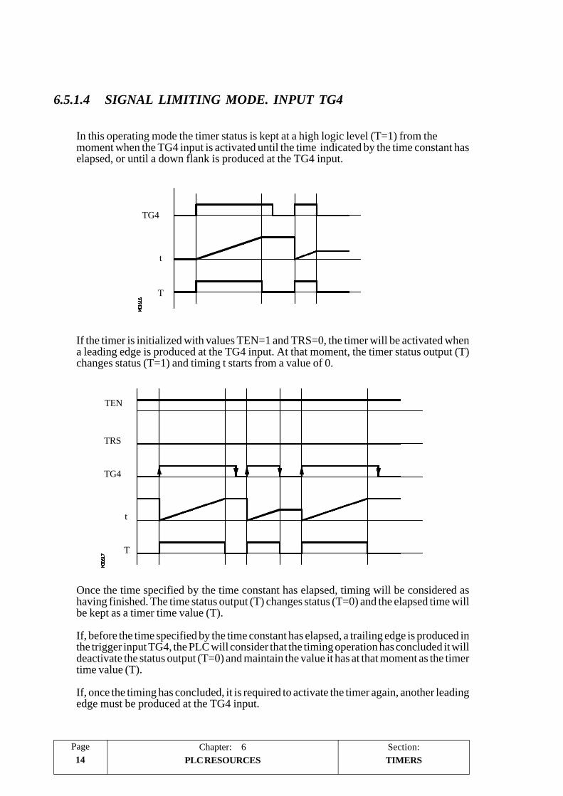
Section:Chapter: 614
Page
PLC RESOURCES
TG4
t
T
TEN
TRS
TG4
t
T
TIMERS
6.5.1.4 SIGNAL LIMITING MODE. INPUT TG4
In this operating mode the timer status is kept at a high logic level (T=1) from themoment when the TG4 input is activated until the time indicated by the time constant haselapsed, or until a down flank is produced at the TG4 input.
If the timer is initialized with values TEN=1 and TRS=0, the timer will be activated whena leading edge is produced at the TG4 input. At that moment, the timer status output (T)changes status (T=1) and timing t starts from a value of 0.
Once the time specified by the time constant has elapsed, timing will be considered ashaving finished. The time status output (T) changes status (T=0) and the elapsed time willbe kept as a timer time value (T).
If, before the time specified by the time constant has elapsed, a trailing edge is produced inthe trigger input TG4, the PLC will consider that the timing operation has concluded it willdeactivate the status output (T=0) and maintain the value it has at that moment as the timertime value (T).
If, once the timing has concluded, it is required to activate the timer again, another leadingedge must be produced at the TG4 input.

PageChapter: 6 Section:15PLC RESOURCES
Operation of the TRS input in this mode
If a leading edge is produced at the TRS input at any moment during timing or afterwards,the PLC initializes the timer, assigning the value 0 to its T status and cancelling its count(it initializes this to 0). Due to the fact that the timer is initialized, it will be necessary toactivate its trigger input to activate it again.
Operation of the TEN input in this mode
If, once the timer is activated, TEN = 0 is selected, the PLC stops timing, and it is necessaryto assign TEN = 1 for this timing to continue.
TRS
TG4
TEN
t
T
t
T
TG4
TRS
TEN
TIMERS

Section:Chapter: 616
Page
PLC RESOURCES COUNTERS
6.6 COUNTERS
These are elements capable of counting up or down a specific number of events. They donot have image values and are represented by the letter C, followed by the counter numberwhich it is required to reference, for example C1, C25, C102, etc.
The count of a counter is stored in a 32-bit variable, thus having a possible value of up to+2147483647.
The PLC has 256 counter, each of which has the C status output and CUP, CDW, CENand CPR inputs. It is also possible to consult the count value at any time.
COUNT UP INPUT (CUP)
This input allows the counter count to be increased in a unit every time a leading edge isproduced in it. It is referred to by the letters CUP followed by the counter number whichis required to reference, for example CUP 1, CUP 25, CUP 102, etc.
Example:
I2 = CUP 10 ; Every time a leading edge is produced at input I2 the countercount C10 will be increased.
COUNT DOWN INPUT (CDW)
This input allows the counter count to be decreased in a unit every time a leading edge isproduced in it. It is referred to by the letters CDW followed by the counter number whichis required to reference, for example CDW 1, CDW 25, CDW 102, etc.
Example:
I3 = CDW 20 ; Every time a leading edge is produced at input I3 the countercount C20 will be decreased.
C 1/256
CEN
CPR
CUP
CDW
C
c

PageChapter: 6 Section:17PLC RESOURCES
ENABLE INPUT (CEN)
This input allows the internal counter count to be stopped. It is referred to by the letters CPRfollowed by the number of the counter which is required to reference for example CEN 1,CEN 25, CEN 102, etc.
In order to be able to modify the internal count by means of the inputs CUP and CDW thisinput must be at logic level “1”. By default and every time a counter is activated the PLCwill assign logic level “1” to this input.
If CEN = 0 is selected the PLC stops the counter count, ignoring the inputs CUP and CDWuntil this input allows it (CEN = 1).
Example:
I10 = CEN 12 ; Input I10 controls the Enable input of counter C12
PRESET INPUT (CPR)
This input allows the counter to be preset with the desired value. It is referred to by the lettersCPR followed by the number of the counter which is required to reference and the valueto be assigned to the counter count.
For example CPR 1 100, CPR 25 224, CPR 102 0, CPR 200 500, etc.
The value of the count can be indicated by means of a numerical value or by assigning toit the internal value of an R register.
CPR 20 100 ; Presets the C20 counter with the value 100.
CPR 22 R200 ; Presets the C22 counter with the value of the Register 200when the instruction is executed.
The counter is preset with the value when a leading edge is produced at the CPR input.
CEN
CUP
CDW
C
c0
COUNTERS

Section:Chapter: 618
Page
PLC RESOURCES
STATUS OUTPUT (C)
This output indicates the logic status of the counter. It is referred to by the letter C followedby the counter number which it is required to reference, for example C1, C25, C102, etc.
The logic status of the counter will be C=1 when the value of the count is zero and C=0 inthe remainder of cases.
COUNT VALUE (C)
This output indicates the value of the internal counter count. It is referred to by the letter C,followed by the counter number which is required to reference, for example C1, C25, C102,etc.
Although when written C123 it coincides with the Status Output, both are different and, areused in different types of instructions.
In binary type instructions function C123 makes reference to the counter’s logic status.
C123 = M100 ; Assigns mark to M100 the (0/1) status of counter 123
In arithmetic and function comparison instructions C123 makes reference to the internalcounter count.
I2 = MOV C123 R200 ; Transfers the count of C123 to register R200
CPS C123 GT 1000 = M100 ; Compares whether the count of C123 is greaterthan 1000, in which case it activates markM100.
The PLC has a 32-bit variable to store the count of each counter.
COUNTERS

PageChapter: 6 Section:19PLC RESOURCES
6.6.1 THE OPERATING MODE OF A COUNTER
If the CEN counter input is initialized (CEN=1), the counter allows its count to be increasedand decreased by means of the CUP and CDW inputs.
Operation of CUP and CDW inputs
Every time a leading edge is produced at the CUP input the counter increases its count byone count.
Every time a leading edge is produced at the CDW input the counter decreases its count byone count.
Operation of the CPR input
If a leading edge is produced at the CPR input the internal count value will take the newvalue assigned.
Operation of the CEN input
If CEN = 0 is selected the counter ignores both up-count (CUP) and down-count (CDW)inputs, it being necessary to assign CEN = 1 for the counter to take notice of these inputs.
COUNTERS

PageChapter: 7 Section:1PROGRAMMING THE PLC
7. PLC PROGRAMMING
The PLC program is structured by modules and it could consist of:
Main module (PRG)Periodic Execution module (PE)First Cycle module (CY1)
Every time the PLC program starts running, the CNC will execute first, if it has beendefined, the First Cycle module (CY1). Then it will execute the Main Program module(PRG) continuously until the PLC program is stopped.
The periodic execution modules (PE) will be executed every so often with the frequencyestablished for each of them. This time period starts counting from the time the CY1 cycleis ended. The execution of a periodic module temporarily interrupts the execution of themain module.
When defining the PLC program, both the processing of the main module (PRG) and theperiodic modules (PE) must be taken into consideration.
Both are described next. Nevertheless, the chapter on "Introduction to the PLC" furtherelaborates on PLC program execution including the processing of the main module.
PRG
CY1
PE
PE

Chapter: 72
Page
PROGRAMMING THE PLCSection:
Physical I Real I
Logic CNCOutputs
Real O Physical O
Real Values Image Values
Logic CNC Inputs
This cyclic processing of the main module is done as follows:
1. It allocates the current values of physical CNC inputs (AXES and I/O moduleconnectors) to the "I" resources of the PLC.
2. It allocates the current values of the logic CNC outputs (CNCREADY, START,FHOUT, .....) to PLC resources M5500 thru M5957 and R550 thru R562 .
3. It runs the main module.
4. It updates the Logic CNC inputs (/EMERGEN, /STOP, /FEEDHOL, ...) with thecurrent values of PLC resources M5000 thru M5465 and R500 thru R505.
5. Allocates the current values of PLC "O" resources to the physical outputs (connectorsof the Axes and I/O modules).
6. It copies the real values of the I, O and M resources into their own image values.
The resources having an image value are: I1 thru I256, O1 thru O256 and M1 thruM2047
7. It concludes this cycle scan and it gets ready for the next one.

PageChapter: 7 Section:3PROGRAMMING THE PLC
The periodic module is optional and it is executed every so often as indicated by the directinginstruction defining the module.
It is used to process certain critical inputs and outputs which cannot be properly evaluatedwithin the main module because the cycle scan time for the main module would be too longfor these resources to be checked and reacted upon.
It does not modify the status of the PLC resources. Therefore, the main module willresume execution as if the Periodic Module had not been executed at all.
The periodic module (PE) is processed as follows:
1. The PLC takes into account the current values, as just before executing the PE module,of the physical inputs (connectors of the Axes and I/O modules).
2. It runs the Periodic Module.
3. It assigns to the physical outputs (connectors of the Axes and I/O modules) the currentvalues of the "O" resources of the PLC.
4. It ends the execution of the Periodic Module and resumes the execution of the MainModule.

Chapter: 74
Page
PROGRAMMING THE PLCSection:
ACTION
LOGICEXPRESSION ACTION
ACTION
STRUCTURE OF A MODULE
7.1 STRUCTURE OF A MODULE
The modules which make up the PLC program (main module "PRG", periodic modules"PE" and first cycle module "CY1") consist of a series of Instructions which, dependingon their functionality, can be divided into:
- Directing instructions.- Executable instructions.
Directing Instructions provide the PLC with information on the type of module and on theway it must execute it.
Executable Instructions allow enquiries to be made on and/or alterations to the status of PLCresources (I,O,M,R,T,C) and consist of:
- A Logic Expression (Boolean 0/1).- One or several Action instructions.
A Logic Expression consists of:
- One or several Enquiry Instructions on resource status- One or several Operands.
Therefore, the structure of a module can be summed up as follows:
Directing instruction (PRG) Consulting instruction
PLC Module Logic expression (I1) (I1 AND I2) Operand Executable instruction (AND)
(I1 AND I2 =O2) Action instruction (=O2)

PageChapter: 7 Section:5PROGRAMMING THE PLC
The PLC allows all the program lines to be associated with any type of information in theform of a comment. This comment will begin with the character “;” and if a line begins withthis character the entire line will be considered as a comment and will not be executed.
Atention:
Empty lines are not allowed, they must contain at least one comment.
Programming example:
PRG ; Directing Instruction———-I100 = M102 ; Executable Instruction———-I28 AND I30 ; Logic Expression= O25 ; Action Instruction———-I32 ; Consulting instruction (I32)AND I36 ; Operand (AND) and consulting instruction (I36)= M300 ; Action instruction———-END ; Directing Instruction
STRUCTURE OF A MODULE
Chapter: 76
Page
PROGRAMMING THE PLCSection:
DIRECTINGINSTRUCTIONS
7.2 DIRECTING INSTRUCTIONS
These provide the PLC with information on the type of module and the way it must beexecuted.
Directing instructions available at the PLC for programming are PRG, PE, CY1, END, L,DEF, IMA, REA, IRD, OWR, MRD, MWR and TRACE.
PRG, PE, CY1: Define the module type.
PRG Main moduleCY1 First cycle modulePE Periodic module. This will be executed periodically every time t (in milliseconds)
indicated in the directing instruction itself. For example: PE1 100 ; This willbe executed every 100 milliseconds.
END: Indicates the end of the module. If this is not defined, the PLC understands that thismodule ends in the last block of the program.
Example of programming using the directing instruction END:
CY1 ; Beginning of module CY1——-——-END ; End of module CY1PRG ; Beginning of module PRG——-——-END ; End of module PRGPE1 100 ; Beginning of module PE——-——-END ; End of module PE
Example of programming without using the directing instruction END:
CY1 ; Beginning of module CY1——-——-PRG ; Beginning of module PRG——-——-PE1 100 ; Beginning of module PE——-—— ; End of modules CY1, PRG and PE

PageChapter: 7 Section:7PROGRAMMING THE PLC
L: Label. used to identify a program line, and is only used when references or programjumps are made.
It will be represented with the letter L followed by three figures (1-256), it not beingnecessary to follow any order and numbers out of sequence are permitted.
If there are 2 or more labels with the same number in a single program, the PLC willshow the corresponding error when compiling it.
DEF: Definition of symbol. Allows a symbol to be associated with any PLC variable, itbeing possible to reference this variable throughout the program by means of thevariable name or by means of the associated symbol.
Example:
DEF EMERG I1 ; Assigns the EMERG symbol to input 11, so any referencethroughout the program to EMERG will be interpreted by thePLC as a reference to I1.
It is also possible to associate a symbol to any number which can be given in decimal,with or without a sign, or hexadecimal format preceded with the “$” sign.
This option, among other applications, makes programming and later understandingof the PLC program much easier when trying to control the CNC by simulating itskeyboard from the PLC program.
Example:
DEF HELP $FFF2 Assigns the symbol “HELP” to the HELP key onthe front panel. The word “HELP” is easier tohandle throughout the program than the “$FFF2”code.
()= MOVE HELP R101 Assigns the code corresponding to the “HELP”key to register R101. (R101 = $FFF2).
CNCWR (R101, KEY, M101) Indicates to the CNC that the key whose code($FFF2) is stored in register R101 (HELP key)has been pressed.
The PLC allows up to 200 symbol definitions which must always be programmedat the beginning of the program, before any other instruction, be this directing orexecuting.
A symbol will be made up with up to 8 characters, and must not coincide with anyof the words reserved for instructions, nor be formed by the characters space” “,equal “=”, open and close parentheses “( )”, comma and semicolon “, ;”.
It is not possible to define duplicated symbols, but it is possible to assign more thanone symbol to the same variable.
Example: DEF EMRGOUT O1DEF SALEMRG O1
The symbols associated to specialized marks and register (M>2047 y R 500) arepre-defined in the PLC and, therefore, it is not necessary to define them, neverthelessand if required, the PLC allows a different symbol to be assigned to them.
>
DIRECTING INSTRUCTIONS

Chapter: 78
Page
PROGRAMMING THE PLCSection:
REA, IMA: Indicate to the PLC that the consultations defined below will be made on thereal (REA) or image (IMA) values of I, O, M resources.
Counters. Timers and Registers do not have image values, so their real values willalways be evaluated.
Action instructions (=O32) will always update the real values of PLC resources.
Example:
IMA ; Consultations will evaluate Image values.I1 AND I2 = O1———————REA ; Consultations will evaluate Real values.———————IMA I3 AND REA M4 = O2 ; Evaluates the Image of I3 and the Real of
M4IMA I5 REA = O3 ; Evaluates the Image of I5 and the next ones
in Real———————
IRD: Updates the real values of the inputs after reading the physical inputs.
Care must be taken when using this instruction since the current real values of theinputs will be lost. After executing this instruction, the new values will match thoseof the physical inputs coming from the electrical cabinet.
MRD: Updates the values of resources M5000 thru M5957 and R500 thru R559 with thevalues of the logic outputs of the CNC.
Care must be taken when using this instruction since the current values of thoseresources will be lost. After executing this instruction, the new values will matchthose of the logic outputs of the CNC (internal variables).
OWR:Updates the physical outputs (electrical cabinet) with the current real values of thecorresponding O resources.
MWR:Updates the logic inputs of the CNC (internal variables) with the current real valuesof resources M5000 thru M5957 and R500 thru R559.
DIRECTING INSTRUCTIONS

PageChapter: 7 Section:9PROGRAMMING THE PLC DIRECTING INSTRUCTIONS
TRACE: This instruction is used when working with the Logic Analyzer in order tocapture data during the execution of the PLC cycle.
It must be born in mind that the logic analyzer performs a data capture at thebeginning of each cycle (PRG and PE) after reading the physical inputs andupdating the marks corresponding to the CNC logic outputs and just beforestarting the program execution.
Use this instruction to carry out another data capture while executing the PLCcycle.
Example of how to use the "TRACE" instruction:
PRG
----------------------TRACE ; Data capture----------------------TRACE ; Data capture----------------------TRACE ; Data capture----------------------
END
PE5-----------TRACE ; Data capture-----------
END
The data capture in the execution of the trace in this program takes place:
- At the beginning of each PRG cycle- Every time the periodic cycle (PE) is executed (every 5 milliseconds)- 3 times while executing the PRG module.- Once while executing the PE module.
This way, by means of the "TRACE" instruction the data capture can be doneany time, especially at those program points considered more critical.
This instruction must only be used when debugging the PLC program and itshould be avoided once the PLC program is fully debugged.

Chapter: 710
Page
PROGRAMMING THE PLCSection:
7.3 CONSULTING INSTRUCTIONS
Consulting instructions allow the PLC to evaluate the status of the different PLC resources(Input, Output, Mark, Timer, Counter) and are divided into:
Simple Consulting InstructionsFlank Detection Consulting InstructionsComparative Consulting Instructions
All the consulting instructions allow the previous operand NOT, which reverses the resultof the preceding consultation.
Example:
NOT I1 ; This Consultation will return a "0" if input I1 is at 1; and a "1" when inputI1 is at 0.
7.3.1 SIMPLE CONSULTING INSTRUCTIONS
These are instructions which test the status of the PLC, inputs, outputs, marks, timers,counters and register bits, returning their logic status.
Example:
I12 ; Will return a 1 if input 12 is active and a 0 if otherwise.
CONSULTINGINSTRUCTIONS

PageChapter: 7 Section:11PROGRAMMING THE PLC
7.3.2 FLANK DETECTION CONSULTING INSTRUCTIONS
They are instructions which verify whether a status change has occurred at the specifiedinput, output or mark.
This comparison may be carried out with the real or image values of the resources and theywill be done between their current value and the one which the resources had when theinstruction was executed last.
There are two types of Flank Detection Consulting Instructions:
DFU: Detects whether an Up Flank (leading edge), a change of status from 0 to1 has been produced in the specified variable. It will return a “1” if that isthe case.
DFD: Detects whether a Down Flank (trailing edge), a change of status from 1to 0 has been produced in the specified variable. It will return a “1” if thatis the case.
The programming format of the different combinations is:
DFU I 1/256DFD O 1/256
M 1/5957
The consulting instructions to detect the flanks of marks M4000 thru M4127, M4500 thruM4563, M4700 thru M4955 and M5000 thru M5957 will be executed with their real valueseven when working with image values since these marks have no image values.
Considering that these instructions can evaluate real and image values, the following pointsmust be taken into account:
* The PLC updates the real values of the inputs at the beginning of the cycle, taking thevalues of the physical inputs.
* The image values of the inputs, outputs and marks are updated after executing theprogram cycle.
CONSULTINGINSTRUCTIONS
1st IMAGE of I3
Real I3
Physical I3

Chapter: 712
Page
PROGRAMMING THE PLCSection:
7.3.3 COMPARATIVE CONSULTING INSTRUCTIONS
The PLC has a CPS instruction which makes comparisons between:
- The time elapsed in a timer (T).- The internal count of a counter (C).- The value of a register (R).- An integer number within ±2147483647
The different types of comparison which can be made are:
GT (Greater than) Checks whether the first operand is GREATER than the second one.GE (Greater equal) Checks whether the first operand is GREATER than or EQUAL to the second one.EQ (Equal) Checks whether the first operand is EQUAL to the second one.NE (Not equal) Checks whether the first operand is DIFFERENT from the second one.LE (Less equal) Checks whether the first operand is LESS than OR EQUAL to the second one.LT (Less than) Checks whether the first operand is LESS than the second one.
The programming format of the different combinations is:
CPS T 1/256 GT T 1/256C 1/256 GE C 1/256R 1/559 EQ R 1/559# NE #
LELT
Where the Registers can be R1/256 or R500/559 and the symbol # represents a definednumber in one of the following formats:
Decimal : Any integer within ±2147483647.Hexadecimal : Preceded by the sign $ and between 0 and FFFFFFFFBinary : Preceded by the letter B and made up of up to 32 bits (1 or 0).
If the required condition is met, the consulting instruction will return the logic value “1”;otherwise, value “0” is returned.
Programming examples:
CPS C12 GT R14 = M100 ; If the internal count of counter C12 is GREATERthan the value of register R14, the PLC will makeM100 = 1 and M100=0 in the opposite case.
CPS T2 EQ 100 = TG1 5 2000 ; When the time elapsed on the counter T2 isEQUAL to the value of 100, timer T5 will beactivated working as a monostable and with a timeconstant of 2 seconds.
CONSULTINGINSTRUCTIONS

PageChapter: 7 Section:13PROGRAMMING THE PLC
7.4 OPERATORS
An operator is a symbol which indicates the logic manipulations which must be made withina Logic Expression, between the different Consulting Instructions. The PLC has thefollowing operators:
NOT Inverts the result of the Consulting Instruction which it precedes.
NOT I2 = O3 ; Output O3 will show the negated status of input I2.
I2 O3
0 11 0
AND Carries out the logic function “AND” between consulting instructions.
I4 AND I5 = O6 ; Output O6 will show the high logic level when input I4 andinput I5 have a high logic level.
I I5 O6
0 0 00 1 01 0 01 1 1
OR Carries out the logic function “OR” between consulting instructions.
I7 OR I8 = O9; Output O9 will show the high logic level when input I7 orinput I8 have a high logic level.
I7 I8 O9
0 0 00 1 11 0 11 1 1
O3
I2
I7 I8
O9
I4
I5
O6
OPERATORS

Chapter: 714
Page
PROGRAMMING THE PLCSection:
XOR Carries out the logic function “EXCLUSIVE OR” between consultinginstructions.
I10 XOR I11 = O12 ; Output O12 will show the high logic level wheninputs I10 and I11 have different logic levels.
I10 I11 O12
0 0 00 1 11 0 11 1 0
The associativity of all these Operators is left to right and the priorities set by the PLCfor their use, classified from highest to lowest, are:
NOTANDXOROR
Besides, the PLC allows the operators “(“ and “)” to be used for clarifying and selecting theorder in which the evaluation of the logic expression is produced.
Example:
(I2 OR I3) AND (I4 OR (NOT I5 AND I6)) = O7
A consulting instruction formed exclusively by the operators “(“ and “)” always has a valueof “1”, i.e.:
() = O2 ; Output O2 will always show the logic value “1”.
I 10
I 11
O12
O7
I2 I3
I5
I6I4
OPERATORS

PageChapter: 7 Section:15PROGRAMMING THE PLC ACTION INSTRUCTIONS
7.5 ACTION INSTRUCTIONS
Action Instructions allow the status of PLC resources (I,O,M,R,T,C) to be altered inaccordance with the result obtained in the logic Expression.
An executing Instruction is made up of a Logic Expression and one or several ActionInstructions, and all Action Instructions must be preceded by the equal symbol (=).
Example:
I2 = O3 = M100 = TG1 2 100 = CPR 1 100
Output O3 and the mark M100 will show the status of input I2, while a leading edgeat input I2 will activate the trigger input TG1 of timer T2 and counter C1 will be presetwith value 100.
All Action Instructions allow a previous NOT, which reverses the result of the expressionfor that action.
Example:
I2 = O3 = NOT M100 = NOT TG1 2 100 = CPR 1 100
Output O3 will show the status of input I2.
Mark M100 will show the negated status of input I2.
A trailing edge (negated leading edge) at input I2 will activate the trigger input TG1of timer T2.
A leading edge at input I2 will preset counter C1 with value 100.
Action instructions are divided into:
- Binary Action Instructions- Sequence Breaking Action Instructions- Arithmetic Action Instructions- Logic Action Instructions- Specific Action Instructions

Chapter: 716
Page
PROGRAMMING THE PLCSection:
7.5.1 BINARY ACTION INSTRUCTIONS
Binary Action Instructions are divided into:
Assignment Binary Action InstructionsConditioned Binary Actions Instructions
7.5.1.1 ASSIGNMENT BINARY ACTION INSTRUCTIONS
This type of binary actions assigns the value obtained in the evaluation of the LogicExpression (0/1) to the specified PLC resource (inputs, outputs, marks, timers, counters andregister bit).
Examples:
I3 = TG1 4 100
The PLC assigns the status of input I3 to the trigger input TG1 of timer T4,thereby the leading edge at input I3 will activate trigger input TG1 of timer T4.
(I2 OR I3) AND (I4 OR (NOT I5 AND I6)) = M111
The PLC assigns to Mark M111 the value obtained in the evaluation of the LogicExpression (I2 OR I3) AND (I4 OR (NOT I5 AND I6)) .
ACTION INSTRUCTIONS

PageChapter: 7 Section:17PROGRAMMING THE PLC
7.5.1.2 CONDITIONED BINARY ACTION INSTRUCTIONS
The PLC has 3 Conditioned Binary Action Instructions, SET, RES and CPL, which allowthe status of the specified Input, Output or Register Bit to be modified.
The programming format for these is as follows:
Marks can be M1/2047, M4000/4127, M4500/4563, M4700/4955 or M5000/5957 andRegisters R1/256 or R500/559
=SET If the result obtained in the evaluation of the logic Expression is a “1” this actionassigns a “1” to the Input, Output, Mark or Register Bit specified. If the result is alogic “0”, this action will not modify the status of the specified resource.Example:
CPS T2 EQ 100 = SET B0R100
When the time elapsed in the timer T2 equals 100, bit 0 of register R100 will beset to “1”.
=RES If the result obtained in the evaluation of the logic Expression is a “1” this actionassigns a “0” to the Input, Output, Mark or Register Bit specified. If the result is alogic “0”, this action will not modify the status of the specified resource.Example:
I12 OR NOT I22 = RES M55 = NOT RES M65
When the result of the logic expression I12 OR NOT I22 is a “1”, the PLC will setmark M55 to “0” and it will not modify mark M65. On the other hand, if the resultis “0”, the PLC will not modify the status of mark M55, but it will set mark M65to “0”.
=CPL If the result obtained in the evaluation of the logic Expression is a “1” this actioncomplements the status of the Input, Output, Mark or Register Bit specified. If theresult is a logic “0”, this action will not modify the status of the specified resource.Example:
DFU I8 OR DFD M22 = CPL B12R35
Every time an Up Flank (leading edge) is detected at input I8 or a Down Flank(trailing edge) in mark M22 the PLC will complement the status of bit 12 of RegisterR35.
SET I 1/256RES O 1/256CPL M 1/5957
B 0/31 R 1/559
ACTION INSTRUCTIONS

Chapter: 718
Page
PROGRAMMING THE PLCSection:
7.5.2 SEQUENCE BREAKING ACTION INSTRUCTIONS
These actions interrupt the sequence of a program, and its execution continues from anotherexecuting instruction indicated by means of a label (L 1/256). This label may be situatedbefore or after the executing instruction in which the action is indicated.
A subroutine is a section of a program which, once is properly labeled, can be called upoNfrom any executable instruction.
The first instruction of a subroutine will be its label (L1 thru L256) and its last will be thedirecting instruction END after the last executable instruction of the subroutine.
If END is not programmed as end of subroutine, the PLC will continue executing until itreaches the next END instruction in the program. At this point the PLC will consider theexecution of the subroutine “ended”.
It is advisable to place the subroutines after the END of the main program since if these areplaced at the beginning, the PLC will start to execute them and will interpret the END ofthe subroutine as the END of the module, and it will consider that this has finished becauseno call was made to the subroutine.
= JMP L1/256 Unconditional Jump
If the result obtained in the evaluation of the logic Expression is a “1” this action causesa jump to the specified label, the execution of the program continuing in the executinginstruction indicated by this label. If the result is a logic “0”, this action will be ignoredby the PLC.
Example:
————————I8 = JMP L12 ; If I8=1 the program continues in L12NOT M14 AND NOT B7R120 = 08 ; If I8=1 it is not executedCPS T2 EQ 2000 = O12 ; If I8=1 it is not executed————————L12(I12 AND I23) OR M54 = 06————————
ACTION INSTRUCTIONS

PageChapter: 7 Section:19PROGRAMMING THE PLC ACTION INSTRUCTIONS
CAL L 1/256 Call to a Subroutine.
If the result obtained in the evaluation of the logic Expression is a “1” this action willexecute the indicated subroutine.
Once this action instruction has concluded, the PLC will continue with the executionof the next action instruction or executing instruction programmed after theCAL L1/256 command.
If the result obtained in the evaluation of the logic Expression is a “0” this action willbe ignored by the PLC without executing the subroutine.
Examples:
I2 = CAL L5 = O2
If input I2 has a value of 1 subroutine L5 will be executed and once this hasconcluded, the PLC will assign the value of input I2 (1) to output O2.
PRG————————I9 = CAL L15 ; If I9=1 it executes subroutine L15————————END ; End of main programL15 ; Beginning of subroutine L15——-—————-(I12 AND I23) OR M54 = 06NOT M14 AND NOT B7R120 = 08CPS T2 EQ 2000 = O12————————END ; End of subroutine L15
= RET Return or End of Subroutine.
If the result obtained in the evaluation of the logic Expression is a “1” this action willbe treated by the PLC as if it involved the directing instruction END. If the result isa logic “0”, this action will be ignored by the PLC.
If, during the execution of a subroutine, the PLC detects an active RET, it will beconsidered that the subroutine has finished as this instruction has a treatment similarto the directing instruction END.
If END is not programmed as the end of a subroutine and if no RET is executed, thePLC will continue executing until it reaches the next END instruction in the program.At this point the PLC will consider the execution of the subroutine “ended”.

Chapter: 720
Page
PROGRAMMING THE PLCSection:
7.5.3 ARITHMETIC ACTION INSTRUCTIONS
The PLC has the following arithmetic Action Instructions: MOV, NGU, NGS, ADS, SBS,MLS, DVS and MDS, which allow working with the specified PLC resources.
=MOV Transfers the logic status of the origin indicated to the specified destination.
This transfer will be of 4, 8, 12, 16, 20, 24, 28 or 32 bits.
The Origin or source of information can be expressed in binary code or BCD and canbe selected from among:
I Input group after the one selected.O Output group after the one selected.M Mark group after the one selected.T Elapsed time of the selected timer.C Counter value of the selected counter.R Value of the selected register.# Number selected in decimal, hexadecimal or binary format.
The Destination or place where the transmitted information is placed can be expressedin binary code or in BCD and can be selected from among:
I Input group after the one selected.O Output group after the one selected.M Mark group after the one selected.R Value of the selected register.
Their programming format is:
Source Destination No.bits to Source Destination Code Code transmit
MOV I 1/256 I 1/256 0(Bin) 0(Bin) 32O 1/256 O 1/256 1(BCD) 1(BCD) 28M 1/5957 M 1/5957 24T 1/256 R 1/559 20C 1/256 16R 1/559 12# 8
Marks can be M1/2047, M4000/4127, M4500/4563, M4700/4955 or M5000/5957and Registers R1/256 or R500/559
The origin and destination codes as well as the number of bits to be transmitted mustbe defined always, except when it is required to transmit Bin to Bin and in 32 bits(0032) in which case it will not be required to program them.
ACTION INSTRUCTIONS

PageChapter: 7 Section:21PROGRAMMING THE PLC ACTION INSTRUCTIONS
Examples:
MOV I12 M100 0032 ; From Binary to Binary in 32 bitsMOV O21 R100 0012 ; From Binary to Binary in 12 bitsMOV C22 O23 0108 ; From Binary to BCD in 8 bitsMOV T10 M112 1020 ; From BCD to Binary in 20 bits
It should be borne in mind that when doing a conversion from binary (origin) to BCD(destination), the number of bits of the new calculated value may have more bits thanthose selected for transmission. If this happens, the PLC will truncate the value ofthe destination, ignoring the most significant digits.
With 4 bits the maximum convertible value in BCD will be 9With 8 bits the maximum convertible value in BCD will be 99With 12 bits the maximum convertible value in BCD will be 999With 16 bits the maximum convertible value in BCD will be 9999With 20 bits the maximum convertible value in BCD will be 99999With 24 bits the maximum convertible value in BCD will be 999999With 28 bits the maximum convertible value in BCD will be 9999999With 32 bits the maximum convertible value in BCD will be 99999999
In order to avoid the loss of these digits, it is suggested that the transfer be madeincreasing the number of bits, using intermediate registers or marks if necessary.
Example:
I11 = MOV I14 O16 108
If input I11 has a value of “1” the PLC transfers the logic states of input I14 andthe next 7 inputs in BCD code, to the 8 outputs starting from O16, in binary code.
BCD
BINARY
ORIGIN
21 20 1819 17 16 1415
1 0 1 0 00 0 1
23 22 2021 19 18 1617
0 1 1 1 00 1 0
92 in BCD
92 in BINARYDESTINA-TION

Chapter: 722
Page
PROGRAMMING THE PLCSection:
=NGU R 1/256 or =NGU R 500/559 Negation Unsigned of all the bits in a Register.
If the result obtained in the evaluation of the logic Expression is a “1” this actionnegates the 32 bits of the specified register (changes the status of each bit).
Example:
I15 = NGU R152
If the input I15 has a value of “1” the PLC negates the 32 bits of register R152.
If register R152 is:
after negating it, the result is:
=NGS R 1/256 or =NGS R 500/559 Changes the sign of the contents of a Register.
If the result obtained in the evaluation of the logic Expression is a “1” this actionchanges the sign to the contents of the specified register.
Example:
I16 = NGS R89
If the input I16 has a value of “1” the PLC changes the sign of the contents ofregister R89.
If register R89 is:
after negating it, it follows:
0 0 1 1 0 0 0 0 1 1 0 0 1 1 0 0 0 1 0 0 0 1 1 0 1 1 0 1 0 1 0 0
1 1 0 0 1 1 1 1 0 0 1 1 0 0 1 1 1 0 1 1 1 0 0 1 0 0 1 0 1 0 1 1
R 89=-818693844
0 0 1 1 0 0 0 0 1 1 0 0 1 1 0 0 0 1 0 0 0 1 1 0 1 1 0 1 0 1 0 0
R 89=+818693844
1 1 0 0 1 1 1 1 0 0 1 1 0 0 1 1 1 0 1 1 1 0 0 1 0 0 1 0 1 1 0 0
ACTION INSTRUCTIONS

PageChapter: 7 Section:23PROGRAMMING THE PLC
=ADS, =SBS, =MLS, =DVS, =MDS
If the result obtained in the evaluation of the logic Expression is a “1”, these actionsallow addition (ADS), subtraction (SBS), multiplication (MLS), division (DVS)and module (MDS) or remainder of a division, operations to be made between thecontents of registers or between the contents of registers and a number. The resultwill always be placed in a specified register.
Their programming format is:
“Operation type” “1st operand” “2nd operand” “destination register”.
The type of operation will be ADS, SBS, MLS, DVS or MDS.
Registers (R1/256 and R500/559) or numbers expressed in decimal, hexadecimalor binary formats can be defined as first and second operands.
The destination register indicates where the result of the operation will bedeposited and will be defined by means of a register (R1/256 or R500/559).
Examples:
If registers R100 = 1234 and R101 = 100
M2047 ; Is always met= ADS R100 R101 R102 ; R102 = 1234 + 100 = 1334= SBS R100 R101 R103 ; R103 = 1234 - 100 = 1134= MLS R100 R101 R104 ; R104 = 1234 x 100 = 123400= DVS R100 R101 R105 ; R105 = 1234 : 100 = 12= MDS R100 R101 R106 ; R106 = 1234 MOD 100 = 34
M2047 ; Is always met= ADS 1563 R101 R112 ; R112 = 1563 + 100 = 1663= SBS R100 1010 R113 ; R113 = 1234 - 1010 = 224= MLS 1563 1000 R114 ; R114 = 1563 x 1000 = 1563000= DVS R100 1000 R115 ; R115 = 1234 : 1000 = 1= MDS 8765 1000 R116 ; R116 = 8765 MOD 1000 = 765
Atention:
If a division by “0” is performed in the DVS operation, the CNC stops theexecution of the PLC program and it displays the corrresponding errormessage.
ACTION INSTRUCTIONS

Chapter: 724
Page
PROGRAMMING THE PLCSection:
7.5.4 LOGIC ACTION INSTRUCTIONS
The PLC has the following logic Action Instructions, AND, OR, XOR, RR and RL.
=AND, =OR, =XOR
If the result obtained in the evaluation of the logic Expression is a “1”, these actionsallow the logic operations AND, OR and XOR to be made bit by bit between thecontents of the register and the number. The result will always be placed in a specifiedregister.
Their programming format is:
“Type of operation” “1st operand” “2nd operand” “destination register”.
The type of operation will be AND, OR or XOR.
Registers (R1/256 and R500/559) or numbers expressed in decimal, hexadecimalor binary format can be defined as first or second operand.
The destination register indicates where the result of the operation will bedeposited and will be defined by means of a register (R1/256 or R500/559).
The mark M2003 is called Zero flag and indicates whether the result of an AND, OR,XOR, operation equals zero, in which case it follows that M2003=1.
Examples:
If registers R200 and R201 have the value of:
R200=B10010010R201=B01000101
M2047 ; Is always met= AND R200 R201 R202 ; R202 = B0 M2003=1= OR R200 R201 R203 ; R203 = B11010111 M2003=0= XOR R200 R201 R204 ; R204 = B11010111 M2003=0
M2047 ; Is always met= AND B1111 R201 R205 ; R205 = B00000101 M2003=0= OR R200 B1111 R206 ; R206 = B10011111 M2003=0= XOR B1010 B1110 R207 ; R207 = B00000100 M2003=0
ACTION INSTRUCTIONS

PageChapter: 7 Section:25PROGRAMMING THE PLC
=RR, =RL Rotation of registers
If the result obtained in the evaluation of the logic Expression is a “1”, these actionsallow the register to be rotated.
It is possible to rotate to the right (RR) or to the left (RL) and there are two types ofrotations: type 1 (RR1 or RL1) and type 2 (RR2 or RL2).
Type 1 rotation (RL1 or RR1):
This type of rotation enters a 0 in the least significant bit (RL1) or in the most significantbit (RR1), by shifting the remaining bits in the register. The value of the last bitdisappears.
Type 2 rotation (RL2 or RR2):
A circular rotation of the register is made, i.e., the most significant bit becomes the newvalue of the least significant bit (RL2) or the least significant bit becomes the new valueof the most significant bit (RR2).
Their programming format is:
“Type of operation” “origin” “No. repetitions” “destination”
The type of operation will be RR1, RR2, RL1 or RL2.
Both the origin and destination will be registers (R1/256 and R500/559). If theorigin and destination registers coincide, it will be necessary to define both.
The number of repetitions will indicate the number of times the register will berotated.
ACTION INSTRUCTIONS
31 . . . . . . . . . . 0
RR1RL1
31 . . . . . . . . . . 0
0 0
RR2RL2
31 . . . . . . . . . . 0 31 . . . . . . . . . . 0

Chapter: 726
Page
PROGRAMMING THE PLCSection:
Examples:
RR1 R100 1 R200 ; 1 type 1 rotation to the right of the contents of R100leaving the result in R200
RL2 R102 4 R101 ; 4 type 2 rotations to the left of the contents of R102leaving the result in R101
If the contents of R17 is:
and M2047 = RL2 R17 4 R20 is executed, the result is:
7.5.5 SPECIFIC ACTION INSTRUCTIONS
=ERA group erase
If the result obtained in the evaluation of the logic Expression is a “1”, this actionallows a group of inputs, outputs, marks or registers to be erased, or to initialize thestatus of a group of timers or counters.
If a group of inputs, outputs, marks or registers is erased; the PLC will assign the value0 to the specified variables.
If a group of timers is erased this is the equivalent of Resetting them and if a group ofcounters is erased this is similar to making a Preset with a value 0 for them.
Their programming format is:
ERA I 1/256 1/256O 1/256 1/256M 1/5957 1/5957T 1/256 1/256C 1/256 1/256R 1/559 1/559
ACTION INSTRUCTIONS
0 0 1 1 0 0 0 0 1 1 0 0 1 1 0 0 0 1 0 0 0 1 1 0 1 1 0 1 0 1 0 0 R 17
R 20
R 17
0 0 0 0 1 1 0 0 1 1 0 0 0 1 0 0 0 1 1 0 1 1 0 1 0 1 0 0 0 0 1 1
0 0 1 1 0 0 0 0 1 1 0 0 1 1 0 0 0 1 0 0 0 1 1 0 1 1 0 1 0 1 0 0

PageChapter: 7 Section:27PROGRAMMING THE PLC
The Marks can be M1/2047, M4000/4127, M4500/4563, M4700/4955 or M5000/5957 and Registers R1/256 or R500/559
This action is especially appropriate for execution in the first cycle module (CY1) withthe aim of setting the required resources in the initial working conditions.
Examples:
I12 = ERA O5 12
If input I12 has a value of “1” the PLC will set to 0 outputs O5 thru O12.
I23 = ERA C15 18
If input I23 has a value of “1” the PLC will preset counters C15 thru C18 to 0.
=CNCRD, =CNCWR Access to internal CNC variables.
These Action Instructions allow reading (CNCRD) and writing (CNCWR) internalCNC variables, their programming format being:
CNCRD (Variable, Register, Mark)CNCWR (Register, Variable, Mark)
If the result obtained in the logic expression is a “1”, the CNCRD action loads thecontents of the indicated Variable into the selected Register, and the CNCWR actionloads the contents of the indicated Register into the selected Variable.
The internal CNC variables which can be accessed by means of these ActionInstructions are detailed in the chapter corresponding to CNC-PLC communications.
If information is requested about a non-existing variable (for example, the coordinatesof an axis which is not used), these actions will not modify the contents of the indicatedregister and will assign a 1 to the selected mark, indicating in this way that the readingof a non-existing variable was requested.
Examples:
CNCRD (FEED, R150, M200)
Loads into register R150 the feedrate value selected at the CNC by means offunction G94.
CNCWR (R92, TIMER, M200)
Presets the timer enabled by the PLC with the value contained in register R92.
ACTION INSTRUCTIONS

Chapter: 728
Page
PROGRAMMING THE PLCSection:
ACTION INSTRUCTIONS
= PAR Register Parity
If the result of the logic expression is a “1”, this action allows to check the type of parityof a register.
Its programming format is:
PAR Register Mark
If the register being checked has an EVEN parity, this instruction will set the indicatedmark to “1” and if its parity is ODD, it will set it to “0”.
Example:
I15 = PAR R123 M222
If I15 = 1 and parity of R123 = EVEN, then M222 = 1If I15 = 1 and parity of R123 = ODD, then M222 = 0

PageChapter: 7 Section:29PROGRAMMING THE PLC
7.6 SUMMARY OF PLC PROGRAMMING INSTRUCTIONS
AVAILABLE PLC RESOURCES
Inputs: I 1/256Outputs: O 1/256Marks (user): M 1/2000
arithmetic flags: M 2001clocks: M 2009/2024set logic level: M 2046/2047associated to messages: M 4000/4127associated to errors: M 4500/4563for screens or pages: M 4700/4955to communicate with CNC: M 5000/5957
Timers: T 1/255Counters:
C 1/255User registers R 1/255Registers to communicate with CNC: R 500/559
The value stored in each register will be considered by the PLC as signed integer whichcould be referred to in the following formats:
Decimal : Any integer number within ±2147483647.Hexadecimal : Preceded by the symbol $ and between 0 and FFFFFFFFBinary : Preceded by the letter B and consisting of up to 32 bits (1 or 0).
DIRECTING INSTRUCTIONS
PRG Main module.CY1 First cycle module.PE t Periodic module. It will be executed every t time (in milliseconds).END End of module.L 1/256 Label.DEF Symbol definition.REA All consultations will be performed on real values.IMA All consultations will be performed on image values.IRD Updates the I resources with the values of the physical inputs.MRD Updates resources M5000/5957 and R500/559 with the values of the logic
outputs of the CNC.OWR Updates the physical outputs with the current real values of the corresponding
O resources.MWR Updates the logic inputs of the CNC (internal variables) with the current real
values of resources M5000/5957 and R500/559.TRACE It captures data for the Logic Analyzer during the execution of a PLC cycle.
SUMMARY OF PLC PRO-GRAMMING COMMANDS

Chapter: 730
Page
PROGRAMMING THE PLCSection:
SIMPLE CONSULTING INSTRUCTIONS
I 1/256 InputsO 1/256 OutputsM 1/5957 MarksT 1/255 TimersC 1/255 CountersB 0/31 R 1/255 Register bit
FLANK DETECTING INSTRUCTIONS
DFU Up flank detection.DFD Down flank detection.
DFU I 1/256DFD O 1/256
M 1/5957
COMPARATIVE INSTRUCTIONS
CPS allows comparisons.
CPS T 1/256 GT T 1/256C 1/256 GE C 1/256R 1/559 EQ R 1/559# NE #
LELT
OPERATORS
NOT Inverts the result of the consulting instruction it precedes.AND Performs the logic function “AND” between consulting instructions.OR Performs the logic function “OR” between consulting instructions.XOR Performs the logic function “EXCLUSIVE OR” between consulting instructions.
ACTION INSTRUCTIONS FOR BINARY ASSIGNMENT
= I 1/256 Inputs= O 1/256 Outputs= M 1/5957 Marks= TEN 1/256 Timers= TRS 1/256= TGn 1/256 n/R= CUP 1/256 Counters= CDW 1/256= CEN 1/256= CPR 1/256 n/R= B 0/31 R 1/256 Register Bits
SUMMARY OF PLC PRO-GRAMMING COMMANDS

PageChapter: 7 Section:31PROGRAMMING THE PLC
CONDITIONED BINARY ACTION INSTRUCTIONS
= SET If the logic expression is “1”, this action assigns a “1” to the resource.If the logic expression is “0”, this action does not change the logic state of theresource.
= RES If the logic expression is “1”, this action assigns a “0” to the resource.If the logic expression is “0”, this action does not change the logic state of theresource.
= CPL If the logic expression is “1”, this action complements the logic state of theresource.
SET I 1/256RES O 1/256CPL M 1/5957
B 0/31 R 1/55
JUMP ACTION INSTRUCTIONS
= JMP L 1/256 Unconditional Jump.= RET Return or End of Subroutine.= CAL L 1/256 Call a Subroutine.
ARITHMETIC ACTION INSTRUCTIONS
= MOV Transfers the logic states of the indicated source to the indicated destination.
Source Destination No.bits toSource Destination Code Code transmit
MOV I 1/256 I 1/256 0(Bin) 0(Bin) 32O 1/256 O 1/256 1(BCD) 1(BCD) 28M 1/5957 M 1/5957 24T 1/256 R 1/559 20C 1/256 16R 1/559 12# 8
4
= NGU R 1/559 Complements all register bits.= NGS R 1/559 Changes the sign of the Register contents.
= ADS Adds the contents of a two registers or a number and a register content.= SBS Subtracts between the contents of two registers or between a number and a
register content.= MLS Multiplies the contents of two registers or a number and a register content.= DVS Divides the contents of two registers or a number and a register content.= MDS Module between registers contents or between a number and a register content.
ADS R1/559 R1/599 R1/559SBS # #MLSDVSMDS
SUMMARY OF PLC PRO-GRAMMING COMMANDS

Chapter: 732
Page
PROGRAMMING THE PLCSection:
LOGIC ACTION INSTRUCTIONS
= AND Logic AND operation between register contents or between a number and aregister content.
= OR Logic OR operation between register contents or between a number and aregister content.
= XOR Logic XOR operation between register contents or between a number and aregister content.
AND R1/559 R1/599 R1/559OR # #XOR
= RR 1/2 Right-hand register rotation.= RL 1/2 Left-hand register rotation.
RR1 R1/559 R1/559 R1/559RR2 0/31RL1RL2
SPECIFIC ACTION INSTRUCTIONS
= ERA Group erase
ERA I 1/25 1/256O 1/256 1/256M 1/5957 1/5957T 1/256 1/256C 1/256 1/256R 1/559 1/559
= CNCRD Read internal CNC variables.
CNCRD (Variable, R1/559, M1/4955)
= CNCWR Write (modify) internal CNC variables.
CNCWR (R1/559, Variable, M1/4955)
= PAR Register Parity
PAR R1/559 M1/5957
SUMMARY OF PLC PRO-GRAMMING COMMANDS

PageChapter: 8 Section:1CNC - PLC COMUNICATION
8. CNC-PLC COMMUNICATION
The exchange of information between the CNC and the PLC allows:
* The control of logic inputs and outputs from the CNC by means of an exchangeof information between both systems, which is done periodically and by meansof specific PLC Marks and Registers.
* The transfer from the CNC to the PLC of M, S and T auxiliary functions.
* Display screens which have been defined previously by the user, as well asgenerating messages and errors in the CNC, by means of specific PLC Marks.
* Reading and writing internal CNC variables from the PLC.
* Access to all PLC variables from any part program.
* Monitoring on the CNC screen of PLC variables.
* Access to all PLC variables from a computer, via DNC through RS 232 C andRS 422 serial lines.
Section:Chapter: 82
Page
CNC - PLC COMUNICATION
8.1 AUXILIARY M, S, T FUNCTIONS
MBCD1 (R550)MBCD2 (R551)MBCD3 (R552)MBCD4 (R553)MBCD5 (R554)MBCD6 (R555)MBCD7 (R556)
The CNC tells the PLC by means of these 32 bit registers, the miscellaneous Mfunctions programmed in the block being executed.
If there are less than 7 miscellaneous M functions in each block, the CNC will sendthe information in the lower-numbered registers, assigning the value $FFFFFFFF tothose which are left free.
Each of these registers contains a coded miscellaneous M function in BCD format (8digits).
M1234 0000 0000 0000 0000 0001 0010 0011 0100LSB
This way, if a block contains functions M100, M120 and M135, the CNC will transferthe following information:
MBCD1 (R550) = $100MBCD2 (R551) = $120MBCD3 (R552) = $135MBCD4 (R553) = $FFFFFFFFMBCD5 (R554) = $FFFFFFFFMBCD6 (R555) = $FFFFFFFFMBCD7 (R556) = $FFFFFFFF
Use one of the following methods to determine whether or not a specific “M” functionhas been programmed in a block which is being executed:
* Check all MBCD registers one by one until the specific “M” function is foundor until one of them contains the $FFFFFFFF value.
* Use the “MBCD*” format which permits checking all MBCD registers at thesame time.
For example, to Detect M30:
CPS MBCD* EQ $30 = .... If detected, it will return a “1” and a “0” ifotherwise.
The miscellaneous M functions can be executed at the beginning or end of the block,according to how these are set in the miscellaneous M function table.
Besides, this table will indicate whether the CNC must wait, or not, for the generallogic input AUXEND to consider the execution of the corresponding M as havingbeen completed.
M, S, T FUNCTIONS

PageChapter: 8 Section:3CNC - PLC COMUNICATION
SBCD (R557)
This register will be used when using a spindle operating with BCD coded S signal.(spindle machine parameter “SPDLTYPE).
The auxiliary S function will always be executed at the beginning of the block and theCNC will wait for the general logic input AUXEND to be activated to consider theexecution completed.
If S output in 2-digit BCD is used the CNC will tell the PLC, by means of this registerthe selected spindle speed according to the following conversion table:
Programmed S “SBCD” Programmed S “SBCD”
0 S00 180-199 S651 S20 200-223 S662 S26 224-249 S673 S29 250-279 S684 S32 280-314 S695 S34 315-354 S706 S35 355-399 S717 S36 400-449 S728 S38 450-499 S739 S39 500-559 S74
10-11 S40 560-629 S7512 S41 630-709 S7613 S42 710-799 S7714-15 S43 800-899 S7816-17 S44 900-999 S7918-19 S45 1000-1119 S8020-22 S46 1120-1249 S8123-24 S47 1250-1399 S8225-27 S48 1400-1599 S8328-31 S49 1600-1799 S84
32-35 S50 1800-1999 S8536-39 S51 2000-2239 S8640-44 S52 2240-2499 S8745-49 S53 2500-2799 S8850-55 S54 2800-3149 S8956-62 S55 3150-3549 S9063-70 S56 3550-3999 S9171-79 S57 4000-4499 S9280-89 S58 4500-4999 S9390-99 S59 5000-5599 S94
100-111 S60 5600-6299 S95112-124 S61 6300-7099 S96125-139 S62 7100-7999 S97140-159 S63 8000-8999 S98160-179 S64 9000-9999 S99
If a value over 9999 is programmed the CNC will tell the PLC the spindle speedcorresponding to value 9999.
M, S, T FUNCTIONS

Section:Chapter: 84
Page
CNC - PLC COMUNICATION
If S output in 8-digit BCD is used the CNC will indicate the programmed spindlespeed to the PLC by means of this register.
This value will be coded in BCD format (8 digits) in thousandths of a revolution perminute.
S12345.678 0001 0010 0011 0100 0101 0110 0111 1000LSB
If no S has been programmed in the block, the CNC will assign a value of$FFFFFFFF to this register.
TBCD (R558)
The CNC tells the PLC by means of this 32-bit register, the pocket number in themagazine where the selected tool is. If the general machine parameter "RANDOMTC"has been set so it is not a random magazine, the magazine pocket position coincideswith the tool number.
This will be coded in BCD format (8 digits).
T123 0000 0000 0000 0000 0000 0001 0010 0011LSB
If no T has been programmed in the block, the CNC will assign a value of$FFFFFFFF to this register.
The T function will always be executed at the beginning of the block and the CNCwill wait for the general logic input AUXEND to be activated to consider theexecution completed.
T2BCD (R559)
This register is used when a special tool change has been made (family code >200)or with machining centers with a non-random tool magazine (general machineparameter “RANDOMTC”).
The CNC tells the PLC by means of the 32 bit register, the position of the magazine(empty pocket) in which the tool which was on the spindle must be deposited.
This will be coded in BCD code (8 digits). If a second T function is not required theCNC will assign a value $FFFFFFFF to the register.
The second T function will be sent together with M06 and the CNC will wait for thegeneral logic input AUXEND to the activated to consider the execution completed.
M, S, T FUNCTIONS

PageChapter: 8 Section:5CNC - PLC COMUNICATION
8.1.1 TRANSFERRING AUXILIARY M, S, T FUNCTIONS
Every time a block is executed in the CNC, information is passed to the PLC about the M,S, and T functions which are active.
M function:
The CNC analyzes the M functions programmed in the block and in accordance withhow these are defined, will send these to the PLC before and/or after the movement.
To do this, it uses variables “MBCD1” to “MBCD7” (R550 to R556) and activatesthe general logic output “MSTROBE” to indicate to the PLC that it must execute them.
Depending on how these functions are defined on the table, the CNC must wait, ornot, for the general input “AUXEND” to be activated to consider the executioncompleted.
S function:
If an S function has been programmed and the spindle has BCD input, the CNC willsend this value to the variable “SBCD” (R557) and will activate the general logicoutput “SSTROBE” to indicate to the PLC that it must be executed.
This transmission is made at the beginning of the block execution and the CNC willwait for the general input “AUXEND” to be activated to consider the executioncompleted.
T function:
The CNC will indicate via the variable “TBCD” (R558) the T function which hasbeen programmed in the block and activates the general logic output “TSTROBE” totell the PLC that it must execute it.
This transmission is made at the beginning of the block execution and the CNC willwait for the general input “AUXEND” to be activated to consider the executioncompleted.
Second T function:
If this involves changing a special tool or a machining center with non-random toolmagazine, the CNC will indicate, on executing the M06 function, the position of themagazine (empty pocket) in which the tool which was on the spindle must bedeposited.
This indication will be made by means of the variable “T2BCD” (R559) and byactivating the general logic output “T2STROBE” to tell the PLC that it must executeit. The CNC will wait for the general input AUXEND to be activated to consider theexecution completed.
It must be borne in mind that at the beginning of the execution of the block, the CNC cantell the PLC the execution of the M, S, T and T2 functions by activating their STROBEsignals together and waiting for a single “AUXEND” signal for all of them.
M, S, T FUNCTIONS

Section:Chapter: 86
Page
CNC - PLC COMUNICATION
8.1.1.1 TRANSFERRING M, S, T USING THE AUXEND SIGNAL
1.- Once the block has been analyzed and after sending the corresponding values in the“MBCD1-7”, “SBCD”, “TBCD” and “T2BCD” variables, the CNC will tell thePLC by means of the general logic outputs “MSTROBE”, “SSTROBE”,“TSTROBE” and “T2STROBE” that the required auxiliary functions must beexecuted.
2.- When the PLC detects the activation of one of the STROBE signals, it must deactivatethe general logic output “AUXEND” to tell the CNC that the execution of thecorresponding function or functions has begun.
3.- The PLC will execute all the auxiliary functions required, it being necessary toanalyze the general logic outputs “MSTROBE”, “SSTROBE”, “TSTROBE”,“T2STROBE” and the variables “MBCD1-7”, “SBCD”, “TBCD” and “T2BCD”.
Once this has been executed the PLC must activate the general logic input“AUXEND” to indicate to the CNC that the processing of the required functionswas completed.
4.- Once the general input “AUXEND” is active, the CNC will require that this signalbe kept active for a period of time greater than that defined by means of the generalmachine parameter “MINAENDW”.
In this way erroneous interpretations of this signal by the CNC are avoided in the caseof malfunctions caused by an incorrect logic in the PLC program.
5.- Once the period of time “MINAENDW” has elapsed with the general input“AUXEND” at a high logic level, the CNC will deactivate the general logic outputs“MSTROBE”, “SSTROBE”, “TSTROBE”, “T2STROBE” to tell the PLC that theexecution of the required auxiliary function or functions has been completed.
Atention:
When the block being executed has several auxiliary functions (M, S, T), theCNC waits a time period set by general machine parameter "MINAENDW"between two consecutive transfers.
1
3 4
2
5
AUXEND
STROBE
M, S, T FUNCTIONS
MINAENDW MI-NAENDW

PageChapter: 8 Section:7CNC - PLC COMUNICATION
8.1.1.2 TRANSFERRING THE AUXILIARY (MISCELLANEOUS) MFUNCTION WITHOUT THE AUXEND SIGNAL
1.- Once the block has been analyzed and after passing the corresponding values invariables “MBCD1-7”, the CNC will tell the PLC through the general logic output“MSTROBE” that the required auxiliary function or functions must be executed.
2.- The CNC will keep the general logic output “MSTROBE” active during the timeindicated by means of general machine parameter “MINAENDW”.
Once this period of time has elapsed the CNC will continue to execute the program.
It is advisable for the “MINAENDW” value to be equal to or greater than the durationof a PLC cycle, in order to ensure the detection of this signal by the PLC.
3.- When the PLC detects the activation of the general logic signal “MSTROBE” it willexecute the required miscellaneous “M” functions in the “MBCD1-7” variables.
1 2 3
PLCEXECUCTION
MSTROBE
M, S, T FUNCTIONS
MI-NAENDW

Section:Chapter: 88
Page
CNC - PLC COMUNICATION
8.2 DISPLAYING MESSAGES, ERRORS AND PAGES ON THE CNC
The PLC has a series of marks which allow messages and errors to be displayed in the CNC,as well as displaying screens which have been defined previously by the user.
Displaying messages
The PLC has 128 marks, with their corresponding mnemonic for displaying messages inthe CNC.
M4000 MSG1M4001 MSG2M4002 MSG3—— ———— ——-M4125 MSG126M4126 MSG127M4127 MSG128
If one of these marks is activated (high logic level), the CNC will display the selectedmessage number and its associated text on the PLC message display window (upper right-hand part).
The CNC allows a text to be associated to each PLC message (PLC message editing mode).
If the PLC activates 2 or more messages, the CNC will always display the message withthe highest priority, this being understood as being the message with the lowest number. Inthis way, MSG1 will have the highest priority and MSG128 the lowest priority.
In this same message display window, the CNC can show the character + (plus sign), whichindicates that there are more messages activated by the PLC, and these can be displayed ifthe active message page option is accessed in the PLC operating mode.
A message can be erased by deactivating it from the PLC program (low logic level) or fromthe CNC keyboard, after selecting it on the active messages page.
Nevertheless and depending on the program, the PLC may reactivate this message in thefollowing cycle.
Example: When changing the status of input I10 (from 0 to 1), messages MSG1 andMSG2 are activated. If, by maintaining I10=1 the user erases the messagesfrom the keyboard, the following may occur in the next PLC cycle:
DFU I10 = MSG1 ; The message will be erased.I10 = MSG2 ; The message will be reactivated.
MESSAGES, ERRORSAND PAGES

PageChapter: 8 Section:9CNC - PLC COMUNICATION
Displaying errors
The PLC has 64 marks, with their corresponding mnemonic, for displaying errors in theCNC.
M4500 ERR1M4501 ERR2M4502 ERR3—— ———— ——-M4561 ERR62M4562 ERR63M4563 ERR64
If one of these marks is activated (high logic level), the CNC part program will be stopped,also displaying the selected error and associated text in the center of the screen.
The CNC allows a text to be associated to each PLC error (PLC error editing mode).
It is recommended to change the state of these marks by means of accessible external inputssince the PLC will not stop and the CNC will receive the error message in each new PLCcycle scan; thus preventing access to any of the PLC modes.
Displaying pages
The PLC has 256 marks with their corresponding mnemonic, for displaying pages on theCNC.
M4700 PIC0M4701 PIC1M4702 PIC2—— ———— ——-M4953 PIC253M4954 PIC254M4955 PIC255
If one of these marks is activated (high logic level), the CNC will display the character *(asterisk) on the PLC message display window (upper right-hand part) indicating that atleast one of the 256 screens (pages) defined by the user in the graphic editor mode isactivated.
The selected screens (pages) will be displayed, one by one, if the active page (screen)page option is accessed in the PLC operating mode.
A page can be deactivated from the PLC program (by placing the corresponding mark atthe low logic level) or, from the CNC keyboard, after selecting it in the active page mode.
MESSAGES, ERRORSAND PAGES

Section:Chapter: 810
Page
CNC - PLC COMUNICATION
8.3 ACCESS FROM THE CNC TO THE PLC PROGRAM AND RESOURCES
The CNC is provided with an operating mode in which it can:
Monitor the user PLC program.Monitor PLC resources.Modify PLC resources.Execute PLC commands (compile, execute, etc.).Etc.
Likewise, the CNC allows access to all PLC variables of any part program and is providedwith several high level language instructions for this purpose, which allow Inputs, Outputs,Marks, Registers, Timers and Counters to be read or modified.
8.4 ACCESS FROM A COMPUTER, VIA DNC, TO PLC RESOURCES
The FAGOR 8050 CNC allows the PLC to communicate with a computer via DNCthrough the RS232C and RS422 serial lines.
In this way a computer can access the PLC carrying out:
Transfer and reception of the user PLC program.Monitoring of the user PLC program.Monitoring of PLC resources.Consultation or modification of PLC resources.Execution of PLC commands (compile, execute, etc.).Etc.
The DNC manual can be applied for from the Commercial Department of FAGORAUTOMATION S. COOP.

PageChapter: 9 Section:1CNC LOGIC INPUTS AND OUTPUTS
9. CNC LOGIC INPUTS AND OUTPUTS
Physical inputs and outputs are the names given to the set of inputs and outputs of the CNCsystem which, being controlled by the PLC, communicate with the outside throughFAGOR 8050 CNC connectors.
The CNC also has a series of logic inputs and outputs for the internal exchange ofinformation with PLC Marks and Registers. This type of marks do not have images on thePLC.
Each of these logic CNC inputs and outputs can be referred to by means of thecorresponding PLC resource or by means of their associated Mnemonic. For example:
M5000 /EMERGENM5016 AUXENDM5104 MIRROR1M5507 /ALARM
Mnemonics which begin with “/” indicate that the signal is active low (0 V.).
All the mnemonics refer to their associated variable, it being necessary to use the NOToperator to refer to its negation, for example:
NOT M5000 —> NOT /EMERGENNOT M5016 —> NOT AUXEND
CNC logic inputs and outputs can be grouped in:
General logic inputs.Key inhibiting logic inputs.Axis logic inputs.Spindle logic inputs.General logic outputs.Axis logic outputs.Spindle logic outputs.

Section:Chapter: 92
Page
CNC LOGIC INPUTS AND OUTPUTS
9.1 GENERAL LOGIC INPUTS
/EMERGEN (M5000) (EMERGENcy stop)
There are two ways to cause an emergency at the CNC, by activating the physicalinput EMERGENCY STOP or by activating the generaL logic input “/EMERGEN”from the PLC.
When the PLC sets the "/EMERGEN" input low (0V), the CNC stops the axes andthe spindle and it displays the corresponding error message.
Also, the CNC activates the "/EMERGENCY OUTPUT" and "/ALARM" signalsto let the outside world and the PLC know that an emergency has occurred at the CNC.
The CNC does not allow executing programs and it aborts any attempt to move theaxes or the spindle while the "/EMERGEN" input is low (0V).
When the PLC brings the "/EMERGEN" input back high (24V), the CNC deactivatesthe "/EMERGENCY OUTPUT" and "/ALARM" signals to let the outside world andthe PLC know that there is no longer an emergency at the CNC.
Example:
I-EMERG AND (other conditions) = /EMERGENIf the external emergency input is activated or any other emergency occurs,general CNC logic input "/EMERGEN" must be activated. When there is noemergency, this signal must be high (24V).
Atention:
This input must always be defined in the PLC program.
GENERAL INPUTS

PageChapter: 9 Section:3CNC LOGIC INPUTS AND OUTPUTS
/STOP (M5001)
When the PLC sets this signal low, the CNC stops the part program, and maintainsspindle rotation.
In order to continue executing the program, as well as setting this signal at a high logiclevel, the general logic input CYSTART must be activated.
The treatment which this /STOP signal receives is similar to that given to the STOPkey on the CNC Front Panel keeping all the keys enabled even when the /STOP signalis at low logic level (0) .
Example: () = /STOP There is always permission to execute the part program.
Atention:
This input must always be defined in the PLC program.
/FEEDHOL (M5002) (FEED HOLd)
When the PLC sets this signal low, the CNC stops the axes (maintaining spindlerotation). When the signal returns to the high logic level, the movement of the axescontinues.
If the /FEEDHOL signal is activated (0V) in a block without motion, the CNC willcontinue the execution of the program until detecting a block with motion.
Example: () = /FEEDHOL There is always permission to move the axes.
Atention:
This input must always be defined in the PLC program.
/XFERINH (M5003) (XFER INHibit)
If the PLC sets this signal low, the CNC prevents the following block from starting,but finishes the one it is executing. When the signal returns to high logic level, the CNCcontinues to execute the program.
Example: () = /XFERINH There is always permission to execute the next block.
Atention:
This input must always be defined in the PLC program.
GENERAL INPUTS

Section:Chapter: 94
Page
CNC LOGIC INPUTS AND OUTPUTS GENERAL INPUTS
CYSTART (M5007) (CYcle START)
If the START key is pressed on the Front Panel of the CNC, this is indicated to thePLC by means of the general logic output START.
If the PLC program considers that there is nothing to prevent the part program formbeing executed, the CYSTART signal must be set at a high logic level, thus beginningthe execution of the program.
The CNC will indicate by means of the general logic output INCYCLE that the programis being executed. As of that moment the CYSTART can return to low logic level.
Example:
START AND (other conditions) = CYSTART
When pressing the Cycle Start key, the CNC activates general logic output "START".The PLC must check that the "other conditions" (hydraulic, safety, etc.) are also metbefore setting general logic input "CYSTART" high so the program starts running.
Atention:
This input must always be defined in the PLC program.
SBLOCK (M5008) (Single BLOCK)
When the PLC sets this signal high, the CNC changes to the Single Block executionmode.
The treatment this signal receives is similar to that given to the Single Block softkey.
MANRAPID (M5009) (MANual RAPID)
If the PLC sets this signal at a high logic level, the CNC selects rapid feed for all themovements executed in JOG Mode.
When the signal returns to a low logic level, the movements executed in JOG modeare made at the previously-selected feedrate.
The treatment which this signal receives is similar to that given to the Rapid Feedratekey on the Control Panel.
OVRCAN (M5010) (OVeRride CANcel)
If the PLC sets this signal at a high logic level, the CNC selects 100% feedrateOVERRIDE, irrespective of whether this is selected by the PLC, DNC, program orby the Front Panel switch.
While the OVERCAN signal is activated (logic 1), the CNC will apply in each mode100 % of the feedrate corresponding to that mode.

PageChapter: 9 Section:5CNC LOGIC INPUTS AND OUTPUTS
LATCHM (M5011) (LATCH Manual)
This allows the type of JOG key operation to be selected in JOG Mode.
If the PLC sets this signal low, the axes will only move while the corresponding JOGkey is pressed.
If the PLC sets this signal at a high logic level, the axes will move from the momentthe corresponding JOG key is pressed until the STOP key or other JOG key is pressed.In this case, the movement will be transferred to that indicated by the new key.
RESETIN (M5015) (RESET IN)
This signal will be treated by the CNC when the JOG mode is selected and there isno movement of the axes or when a program to be executed is selected and it is notrunning.
When there is a rising edge (leading edge) of this signal (change from low to high) theCNC assumes the initial machining conditions selected by the machine parameter.
The CNC will indicate by means of the general logic output RESETOUT that thisfunction has been selected.
The treatment received by this signal is similar to that given to the RESET key on theFront Panel.
GENERAL INPUTS
Section:Chapter: 96
Page
CNC LOGIC INPUTS AND OUTPUTS
AUXEND (M5016) (AUXiliar END)
This signal is used in the execution of auxiliary functions M, S and T, to tell the CNCthat the PLC is executing them.
It operates in the following way:
1.- Once the block has been analyzed and after sending the corresponding valuesin the variables “MBCD1-7”, “SBCD”, “TBCD” and “T2BCD”, the CNC willtell the PLC by means of the general logic outputs “MSTROBE”, “SSTROBE”,“TSTROBE” and “T2STROBE” that the required auxiliary functions must beexecuted.
2.- When the PLC detects that one of the STROBE signals is active, it mustdeactivate the general logic input “AUXEND” to tell the CNC that theexecution of the corresponding function or functions is starting.
3.- The PLC will execute all the auxiliary functions required, it being necessary toanalyze the “MSTROBE”, “SSTROBE”, “TSTROBE”, “T2STROBE”general logic outputs and the “MBCD1-7”, “SBCD”, “TBCD” and “T2BCD”variables in order to do this.
Once execution has been completed, the PLC must activate the general logicinput “AUXEND” to tell the CNC that the treatment of the required functionshas been completed.
4.- Once the general input “AUXEND” has been activated, the CNC will requirethat this signal be kept active for a period of time greater than that defined bymeans of the general machine parameter “MINAENDW”.
In this way, incorrect interpretations of this signal by the CNC are avoided whenmalfunctions are produced by an incorrect logic in the PLC program.
5.- Once the “MINAENDW” time has elapsed, with the general input “AUXEND”at a high logic level, the CNC will deactivate the general logic outputs“MSTROBE”, “SSTROBE”, “TSTROBE”, “T2STROBE” in order to tell thePLC that the execution of the required auxiliary function or functions has beencompleted.
TIMERON (M5017) (TIMER ON)
The CNC is provided with a timer which can be enabled and disabled. By means ofthis logic CNC input, it will be enabled (timing) when the PLC sets the signalTIMERON at a high logic level.
GENERAL INPUTS
AUXEND
STROBE
1
3 4
2
5
MI-NAENDW
MINAENDW

PageChapter: 9 Section:7CNC LOGIC INPUTS AND OUTPUTS GENERAL INPUTS
This general purpose timer can be accessed by means of the internal variable TIMER.An application of this timer is to monitor tool life.
TREJECT (M5018) (Tool REJECT)
The PLC sets this signal at a high logic level in order to tell the CNC to reject the toolin use, even though it may not have come to the end of its service life. An importantapplication is to replace the tool when the PLC detects that it is broken.
PANELOFF (M5019) (PANEL OFF)
The PLC sets this signal high in order to tell the CNC that the front panel keyboard(MONITOR/KEYBOARD) and the keyboard of the CONTROL PANEL of theCNC are deactivated.
It is recommended to change the state of this mark by means of an accessible externalinput since the PLC wil not stop and the CNC will receive the error message in eachnew PLC cycle scan; thus preventing access to any of the PLC modes.
POINT (M5020) (POINT)
This signal is used by the CNC when digitizing point to point while tracing by hand.
Every time an up-flank (leading edge or transition from logic low to high) is detected,the CNC generates a new program point.
PLCABORT (M5022) (PLC ABORT)
The PLC sets this signal high to indicate to the CNC that it must stop the PLC axes.It also cancels the rest of the movement and the possible blocks that might have beensent from the PLC.
Once this process is ended, the CNC automatically deactivates this signals.
The following example shows how the axes controlled by the PLC may be moved bymeans of external push-buttons.
The PLC will order to move the "C" axis by 1 meter every time the "C+" button ispressed, but stopping it when this key is released.
DEF CPLUS I2 ; Define I2 as push-button "C+"DFU CPLUS = CNCEX (G91 G1 C1000 F3000, M1) ; Move 1000mm when button is pressedDFD CPLUS = SET PLCABORT ; Stop when button is released.
On power-up, the CNC sets this mark to "0".

Section:Chapter: 98
Page
CNC LOGIC INPUTS AND OUTPUTS
PLCREADY (M5023) (PLC READY)
This mark indicates the PLC status.
PLCREADY = 0 PLC stoppedPLCREADY = 1 PLC in execution
If this mark is set to 0. the PLC program will stop.
This mark MUST be set to 1 so the CNC allows the spindle and/or the axes to bemoved. Otherwise, it will issue the corresponding error message.
INT1 (M5024)INT2 (M5025)INT3 (M5026)INT4 (M5027)
The PLC sets one of these signals to logic state "1" to "tell" the CNC to interrupt theexecution of the currently running program and jump to execute the interruptionsubroutine whose number is indicated in the general machine parameter "INT1SUB"(P35), "INT2SUB" (P36), "INT3SUB" (P37) or "INT4SUB" (P38) respectively.
All these inputs have the same priority and are active by level (not by flank or edge).Only the first one being detected high ("1") will be attended to.
The status of these signals are not stored; therefore, it is recommended to activate thesemarks at the PLC by means of an instruction of the “SET” type. These marks will bedeactivated automatically when starting the execution of the corresponding subroutine.
An interruption subroutine cannot, in turn, be interrupted.
BLKSKIP1 (M5028) (BLocK SKIP1)
The PLC sets this signal at a high logic level to tell the CNC that the block skipcondition “/ or /1” is met, therefore, the blocks which have this block skip conditionwill not be executed.
BLKSKIP2 (M5029) (BLocK SKIP2)
The PLC sets this signal at a high logic level to tell the CNC that the block skipcondition “/2” is met, therefore, the blocks which have this block skip condition willnot be executed.
BLKSKIP3 (M5030) (BLocK SKIP3)
The PLC sets this signal at a high logic level to tell the CNC that the block skipcondition “/3 is met, therefore, the blocks which have this block skip condition willnot be executed.
M01STOP (M5031) (M01 STOP)
The PLC sets this signal at a high logic level to tell the CNC to stop the execution ofthe part program when the auxiliary (miscellaneous) M01 function is executed.
GENERAL INPUTS

PageChapter: 9 Section:9CNC LOGIC INPUTS AND OUTPUTS
9.2 AXIS LOGIC INPUTS
There are 6 groups of logic inputs (LIMIT, DECEL, etc.) which refer to the 6 possible axesof the machine by means of digits 1 through 6 (LIMIT+2, DECEL1,etc.)
These numbers have nothing to do with the values assigned to the general machineparameters "AXIS1" through "AXIS8".
These variables are numbered according to the logic order of the axes.
For example, if the CNC controls the X, Y, Z, B, C and U axis, the order will be: X, Y, Z,U, B, C and, therefore:
Variables: LIMIT+1, LIMIT-1, DECEL1, etc. correspond to the X axis.Variables: LIMIT+2, LIMIT-2, DECEL2, etc. correspond to the Y axis.Variables: LIMIT+3, LIMIT-3, DECEL3, etc. correspond to the Z axis.Variables: LIMIT+4, LIMIT-4, DECEL4, etc. correspond to the U axis.Variables: LIMIT+5, LIMIT-5, DECEL5, etc. correspond to the B axis.Variables: LIMIT+6, LIMIT-6, DECEL6, etc. correspond to the C axis.
LIMIT+1 and LIMIT-1 (M5100) and (M5101)LIMIT+2 and LIMIT-2 (M5150) and (M5151)LIMIT+3 and LIMIT-3 (M5200) and (M5201)LIMIT+4 and LIMIT-4 (M5250) and (M5251)LIMIT+5 and LIMIT-5 (M5300) and (M5301)LIMIT+6 and LIMIT-6 (M5350) and (M5351)
The PLC sets these signals at a high logic level in order to tell the CNC that thecorresponding axis has overrun the end of its range of movement in the positive (+)or negative (-) direction indicated by the limit switch.
In this case, the CNC stops axis feed and spindle rotation, and displays the correspondingerror on the screen.
In Manual (JOG) Operating Mode the axis which has overrun its range of travel canbe moved in the correct direction in order to place it within the correct range of travel.
AXES INPUTS

Section:Chapter: 910
Page
CNC LOGIC INPUTS AND OUTPUTS
DECEL1 (M5102)DECEL2 (M5152)DECEL3 (M5202)DECEL4 (M5252)DECEL5 (M5302)DECEL6 (M5352)
These signals are used by the CNC when machine reference search is made.
If the PLC sets one of these signals high, this indicates to the CNC that the machinereference search switch of the corresponding axis has been pressed.
When this signal is activated in the machine reference search mode, the CNCdecelerates the axis, changing the rapid approach feedrate indicated by the axismachine parameter “REFEED1”, with the slow feedrate indicated by the axismachine parameter “REFEED2”. After decelerating it accepts the following referencesignal from the corresponding axis feedback system as being valid.
INHIBIT1 (M5103)INHIBIT2 (M5153)INHIBIT3 (M5203)INHIBIT4 (M5253)INHIBIT5 (M5303)INHIBIT6 (M5353)
The PLC sets one of these signals at a high logic level in order to tell the CNC toprevent any movement of the corresponding axis. This movement will continue whenthe PLC sets this signal at the low logic level once more.
If the inhibited axis is moving together with other axes, all these stop moving until thesignal returns to the low logic level.
AXES INPUTS

PageChapter: 9 Section:11CNC LOGIC INPUTS AND OUTPUTS
MIRROR1 (M5104)MIRROR2 (M5154)MIRROR3 (M5204)MIRROR4 (M5254)MIRROR5 (M5304)MIRROR6 (M5354)
If the PLC sets one of these signals at a high logic level, the CNC applies mirror imageto the movement of the corresponding axis.
It must be borne in mind that if this signal is activated during a programmed movement,the CNC will only apply mirror image to the movement, not to the final coordinate.
Example:
N00 G01 X0 Y0 F1000N10 G01 X70 Y42N20 G01 X100 Y60N30 M30
If, when executing the programmed movement in block N20 the signal correspondingto the X axis “MIRROR1” is active, the CNC will apply mirror image to the remainingmovement in X.
This way, the new end of travel point will be X40 Y60.
By means of the activation of these signals, symmetrical parts can be executed by usinga single program, for example, soles of shoes.
In order to obtain the same effect as functions G11, G12, G13 and G14, it is necessaryfor the corresponding axis or axes to be positioned at part zero when these signals areactivated.
AXES INPUTS
10070
42
60
Y
X

Section:Chapter: 912
Page
CNC LOGIC INPUTS AND OUTPUTS AXES INPUTS
DRO1 M5106DRO2 M5156DRO3 M5206DRO4 M5256DRO5 M5306DRO6 M5356
These inputs, together with the corresponding "SERVOON" inputs make it possibleto operate with the axes as DRO.
In order for the axis to work in DRO mode, its "DRO" input must be high and itscorresponding "SERVOON" input must be low.
When an axis works as a DRO, the positioning loop is open and its following erroris ignored while in motion
If the DRO signal is brought back low, the axis will no longer behave as a DRO andthe CNC will take as position value its current position assigning a 0 value to thefollowing error.
SERVO1ON (M5107)SERVO2ON (M5157)SERVO3ON (M5207)SERVO4ON (M5257)SERVO5ON (M5307)SERVO6ON (M5357)
When one of these signals is set high, the CNC closes the positioning loop of thecorresponding axis.
When the signal is set back low, the CNC opens the positioning loop for the axis, butit keeps track of the following error and when the signal comes back up, the CNCmoves the axis to correct for the accumulated following error and gets back in position.
These signals are controlled by the PLC and when the positioning loop is tobe closed,they will be processed by the CNC according to the value given to machine parameter“DWELL” for the axes.

PageChapter: 9 Section:13CNC LOGIC INPUTS AND OUTPUTS AXES INPUTS
SERVOON
ERROR
ENABLE signal
ANALOG OUTPUT
DWELLDWELL
SERVOON
ERROR
ENABLE signal
ANALOG OUTPUT
DWELL = 0
When this parameter for the axis to be moved is set to 0, the CNC will check the statusof the SERVOON signal at the time when the ENABLE must be output.
If the SERVOON signal is high, the CNC allows the movement of this axis byactivating the ENABLE signal and outputting the required analog voltage.
On the other hand, if the SERVOON signal is low or if it changes during themovement of the axes, the CNC stops the axes feed and the spindle rotation displayingthe corresponding error message.
DWELL <> 0
If this machine parameter for the axis to be moved has been assigned a value other than0, the CNC will check the status of the SERVOON signal at the time when that axisENABLE signal must be output.
When this signal (SERVOON) is high, the CNC allows the movement of the axis byactivating the ENABLE signal and providing the required analog output voltage.
On the other hand, if the SERVOON signal is low, the CNC activates the ENABLEsignal and after “waiting” for a time period indicated in DWELL, it checks again thestatus of the SERVOON signal. If it is high, it will output the analog voltage for theservo drive, but if it is still low, it stops the axes feed and the spindle rotation displayingthe corresponding error message.
Also, if the SERVOON signal changes states during the movement of the axis, theCNC stops the axes feed and the spindle rotation displaying the corresponding errormessage.
Section:Chapter: 914
Page
CNC LOGIC INPUTS AND OUTPUTS
AXIS+1 and AXIS-1 (M5108) and (M5109)AXIS+2 and AXIS-2 (M5158) and (M5159)AXIS+3 and AXIS-3 (M5208) and (M5209)AXIS+4 and AXIS-4 (M5258) and (M5259)AXIS+5 and AXIS-5 (M5308) and (M5309)AXIS+6 and AXIS-6 (M5358) and (M5359)
The CNC uses these signals when working in the Manual (JOG) Operating Mode.
If the PLC sets one of these signals high, the CNC will move the corresponding axisin the direction indicated, positive (+) or negative (-). This movement will beperformed at the feedrate override % currently selected.
The treatment which these signals receive is similar to that given to the JOG keys ofthe Control Panel.
SYNCHRO1 (M5112)SYNCHRO2 (M5162)SYNCHRO3 (M5212)SYNCHRO4 (M5262)SYNCHRO5 (M5312)SYNCHRO6 (M5362)
The PLC sets one of these signals high to synchronize the corresponding axis to theaxis defined by the axis machine parameter “SYNCHRO”.
LIM1OFF (M5115) (LIMits 1 OFF)LIM2OFF (M5165) (LIMits 2 OFF)LIM3OFF (M5215) (LIMits 3 OFF)LIM4OFF (M5265) (LIMits 4 OFF)LIM5OFF (M5315) (LIMits 5 OFF)LIM6OFF (M5365) (LIMits 6 OFF)
The PLC sets one of these signals high so that the CNC ignores the software limits ofthe corresponding axis.
AXES INPUTS

PageChapter: 9 Section:15CNC LOGIC INPUTS AND OUTPUTS SPINDLE INPUTS
9.3 LOGIC SPINDLE INPUTS
The mill model 8050 M CNC has one single spindle (main spindle)
The lathe model may have 2 spindles: a main spindle and a second spindle.They both can be operative simultaneously, but only one can be controlled at a time. Thisselection can be made via part-program by means of functions G28 and G29.
LIMIT+S and LIMIT-S (M5450) and (M5451) ............... Main SpindleLIMIT+S2 and LIMIT-S2 (M5475) and (M5476) ........... Second Spindle
The CNC uses these signals when working with the spindle in closed loop (M19).The CNC only considers the signals for the currently selected spindle
The PLC sets one of the signals high to tell the CNC that the spindle has overrun itsrange of travel in the positive (+) or negative (-) direction.
In this case, the CNC stops axis feed and spindle rotation and displays the correspondingerror on screen.
DECELS (M5452) ........................................................ Main SpindleDECELS2 (M5477) .................................................... Second Spindle
The CNC uses this signal while searching home when the spindle changes to workingin closed loop (M19). The CNC only considers the signals for the currently selectedspindle
The PLC sets this signal high to indicate to the CNC that the reference search switchis pressed.
When this signal is activated in the reference search mode the CNC decelerates thespindle, changing the rapid approach speed indicated by the spindle machineparameter “REFEED1”, with the slow feedrate indicated by the spindle machineparameter “REFEED2”. After decelerating, it accepts the following reference signalfrom the spindle feedback systems as being valid.
SPDLEINH (M5453) (SPinDLE INHibit) ................... Main SpindleSPDLEIN2 (M5478) (SPinDLE INHibit) ............... Second Spindle
The CNC considers these two signals at all times so both spindles can be controlledby the PLC.
When the PLC sets this signal high, the CNC outputs a zero analog for the spindle.
SPDLEREV (M5454) (SPinDLE REVerse) ................. Main SpindleSPDLERE2 (M5479) (SPinDLE REverse) ............. Second Spindle
The CNC considers these two signals at all times so both spindles can be controlledby the PLC.
When the PLC sets this signal high, the CNC reverses the programmed spindle turningdirection.
If while being this signal high, a block containing an M3 or M4 is executed, the spindlewill start turning in the opposite direction.

Section:Chapter: 916
Page
CNC LOGIC INPUTS AND OUTPUTS SPINDLE INPUTS
SERVOSON
ENABLE signal
ERROR
ANALOG OUTPUT
SERVOSON (M5457) ........................................................ Main SpindleSERVOSO2 (M5482) .................................................... Second Spindle
These signals are controlled by the PLC and the CNC will process them only whenthe spindle is working in closed loop (M19). Their treatment will depend on the valueassigned to the spindle machine parameter “DWELL”.
DWELL = 0
In this case, the CNC will check the status of the SERVOSON signal at the timewhen the ENABLE signal is to be output.
If the SERVOSON signal is high, the CNC will allow the spindle to rotate byactivating the ENABLE signal and providing the required analog output voltage.
On the other hand, if the SERVOSON signal is low or if it changes to low duringthe rotation of the spindle, the CNC will stop the axes feed and the spindle rotationdisplaying the corresponding error message.

PageChapter: 9 Section:17CNC LOGIC INPUTS AND OUTPUTS
ENABLE signal
DWELL
ERROR
DWELL
ANALOG OUTPUT
SERVOSON
SPINDLE INPUTS
DWELL <> 0
In this case, the CNC will check the status of the SERVOSON signaL at the timewhen the ENABLE signal is to be output.
If the SERVOSON signal is high, the CNC will allow the spindle to rotate byactivating the ENABLE signal and providing the required analog output voltage.
On the other hand, if the SERVOSON signal is low, the CNC will activate theENABLE signal and, after waiting for a time period indicated by the value givento “DWELL”, the CNC checks the SERVOSON signal again. If it is high, therequired spindle analog voltage will be output. If low, the CNC will stop the axesfeed and the spindle rotation displaying the corresponding error message.
Also, if it changes to low during the rotation of the spindle, the CNC will stop theaxes feed and the spindle rotation displaying the corresponding error message.

Section:Chapter: 918
Page
CNC LOGIC INPUTS AND OUTPUTS
MBCD 1-7
M STROBE
AUXEND
GEAR
SPINDLE INPUTS
GEAR1, GEAR2, GEAR3, GEAR4 (M5458), (M5459), (M5460), (M5461)Main Spindle
GEAR12, GEAR22, GEAR32, GEAR42 (M5483), (M5484), (M5485), (M5486)Second Spindle
The PLC uses these signals to indicate to the CNC which spindle speed range iscurrently selected (high logic level). The CNC only considers the signals for thecurrently selected spindle.
When any of the miscellaneous functions M41, M42, M43 or M44 is programmed,the CNC will “tell” the PLC so it selects the desired gear range even if it is alreadyselected.
When working with an automatic gear changer, the CNC will check the currentlyselected gear (GEAR1...GEAR4) and if this does not correspond to the selectedspeed, the CNC will indicate it to the PLC by means of the miscellaneous functionM41, M42, M43 or M44 so it can select it.
Once the PLC selects the proper gear, it indicates it to the CNC by means of the logicinput corresponding to the spindle (GEAR1 thru GEAR4).
The spindle gear change depends on the setting of functions M41 thru M44 in the Mfunction table:
If these functions use the “AUXEND” signal:
The CNC indicates to the PLC the selected range (M41 thru M44) in one of theregisters “MBCD1” thru “MBCD7” and it activates the general logic output“MSTROBE” to “tell” the PLC that it must execute it.
When the PLC detects the activation of the “MSTROBE” signal it mustdeactivate the general logic input “AUXEND” to “tell” the CNC that theexecution of the function has started.
Once executed this function, the PLC will inform the CNC that the new gear hasbeen selected by means of the logic input corresponding to the spindle (GEAR1thru GEAR4).
The PLC, then, activates the logic input “AUXEND” to “tell” the CNC that theexecution of the gear change has been completed.

PageChapter: 9 Section:19CNC LOGIC INPUTS AND OUTPUTS SPINDLE INPUTS
Once the “AUXEND” input activated, the CNC will require that this signal bekept active for a time period greater than the value given to the general machineparameter “MINAENDW”.
This way, erroneous interpretations of this signal by the CNC due to an improperPLC program logic are avoided .
Once the “MINAENDW” time has elapsed with the “AUXEND” general inputkept high, the CNC will check whether the new gear range has been selected byverifying that the corresponding input among GEAR1 thru GEAR4 is set high.
If that is the case, it will deactivate the “MSTROBE” signal to “tell” the PLC thatthe gear change has been completed and if the corresponding GEAR input is notset high, the CNC stops the axes feed and spindle rotation displaying thecorresponding error message.
If these functions do not use the “AUXEND” signal:
The CNC indicates to the PLC the selected gear range M41, M42, M43 or M44in one of the registers “MBCD1” thru “MBCD7” and it activates the “MSTROBE”signal to let the PLC “know” that it must execute it.
The CNC will keep the MSTROBE output active for the time period indicatedby the general machine parameter “MINAENDW”.
After this time, the CNC will check whether the new gear range has beenphysically selected by verifying that the corresponding GEAR input (GEAR1thru GEAR4) is set high.
If it is not selected, the CNC will stop the axes feed and the spindle rotationdisplaying the corresponding error message.
PLCFM19 (M5464) M19FEED (R505) .................... Main SpindlePLCFM192 (M5489) M19FEED2 (R507) ............. Second Spindle
The CNC only considers the signals for the currently selected spindle.
The PLC uses the "PLCM19" signal to indicate to the CNC the positioning andrapid synchrnoized speed value to assume when operating in closed loop (M19).
When this input is low, the CNC assumes the value set by spindle machineparameter "REFEED1" (P34)
When this input is high, the CNC assumes the value set by the spindle inputregister "M19FEED" (R505).
The "M19FEED" value is given in 0,0001º/min.

Section:Chapter: 920
Page
CNC LOGIC INPUTS AND OUTPUTS
PLCCNTL (M5465) (PLC CoNTroL) ....................... Main SpindlePLCCNTL2 (M5490) (PLC CoNTroL) ................... Second Spindle
The CNC considers these 2 signals at all times so both spindles can be controlled bythe PLC.
This is used to tell the CNC that the spindle is controlled directly by the PLC (high logiclevel).
It is used, for example, for oscillating the spindle during gear changes or for changingtools.
The following example shows how a new spindle speed is selected involving a rangechange.
After analyzing the block and detecting the speed change the CNC indicates thisto the PLC in one of the “MBCD1-7” Registers (M41 to M44) and will activatethe general logic output “MSTROBE” to tell the PLC that it must execute it.
The PLC will deactivate the logic input AUXEND to tell the CNC that thetreatment of the auxiliary function is starting.
After calculating the value corresponding to the residual output S for the rangechange, the PLC will indicate this to the CNC by means of the Register“SANALOG”, afterwards setting the signal “PLCCNTL” at a high logic level.
At this time the CNC will send out the output indicated in the RegisterSANALOG.
Once the requested speed change has been made, the new active speed will beindicated to the CNC (spindle logic inputs GEAR1 to GEAR4).
In order to give the control of the spindle back to the CNC, the signal“PLCCNTL” must be set low.
Finally, the PLC will activate the logic input AUXEND once more to tell theCNC that the execution of the auxiliary function has been completed.
MSTROBE
AUXEND
PLCCNTL
MI-NAENDW
SPINDLE INPUTS

PageChapter: 9 Section:21CNC LOGIC INPUTS AND OUTPUTS
SANALOG (R504) ........................................................... Main SpindleSANALOG2 (R506) ....................................................... Second Spindle
The CNC considers these 2 signals at all times so both spindles can be controlled bythe PLC.
The PLC will indicate by means of this 32 bit register the spindle analog output whichthe CNC must send out when it is controlled by the PLC.
SANALOG=32767 corresponds to an analog output of 10 V.
(10/32767) 0.305185 millivolts of analog output correspond to SANALOG=1.
In this way, if an analog output of 4V is required, the following will be programmed:
SANALOG = (4 x 32767)/10 = 13107
And if an analog output of -4V is required, the following will be programmed:
SANALOG = (-4 x 32767)/10 = -13107
SPINDLE INPUTS

Section:Chapter: 922
Page
CNC LOGIC INPUTS AND OUTPUTS
9.4 KEY INHIBITING LOGIC INPUTS
KEYDIS1 (R500)KEYDIS2 (R501)KEYDIS3 (R502)KEYDIS4 (R503)
The PLC can individually inhibit the operation of the panel keys, setting thecorresponding bit of one of these 4 32-bit registers high.
Register Bit Key Inhibited
KEYDIS1 (R500) 0 FKEYDIS1 (R500) 1 LKEYDIS1 (R500) 2 QKEYDIS1 (R500) 3 WKEYDIS1 (R500) 4 SHIFTKEYDIS1 (R500) 5 9KEYDIS1 (R500) 6 6KEYDIS1 (R500) 7 3KEYDIS1 (R500) 8 EKEYDIS1 (R500) 9 KKEYDIS1 (R500) 10 PKEYDIS1 (R500) 11 VKEYDIS1 (R500) 12 CAPSKEYDIS1 (R500) 13 8KEYDIS1 (R500) 14 5KEYDIS1 (R500) 15 2KEYDIS1 (R500) 16 DKEYDIS1 (R500) 17 JKEYDIS1 (R500) 18 OKEYDIS1 (R500) 19 UKEYDIS1 (R500) 20 SPKEYDIS1 (R500) 21 7KEYDIS1 (R500) 22 4KEYDIS1 (R500) 23 1KEYDIS1 (R500) 24 CKEYDIS1 (R500) 25 IKEYDIS1 (R500) 26 ÑKEYDIS1 (R500) 27 TKEYDIS1 (R500) 28 ZKEYDIS1 (R500) 29 =KEYDIS1 (R500) 30 /KEYDIS1 (R500) 31 *
KEY INHIBITING INPUTS

PageChapter: 9 Section:23CNC LOGIC INPUTS AND OUTPUTS
Register Bit Key Inhibited
KEYDIS2 (R501) 0 BKEYDIS2 (R501) 1 HKEYDIS2 (R501) 2 NKEYDIS2 (R501) 3 SKEYDIS2 (R501) 4 YKEYDIS2 (R501) 5 RESETKEYDIS2 (R501) 6 ESCKEYDIS2 (R501) 7 MAIN MENUKEYDIS2 (R501) 8 AKEYDIS2 (R501) 9 GKEYDIS2 (R501) 10 MKEYDIS2 (R501) 11 RKEYDIS2 (R501) 12 XKEYDIS2 (R501) 13 ENTERKEYDIS2 (R501) 14 HELPKEYDIS2 (R501) 15KEYDIS2 (R501) 16 .KEYDIS2 (R501) 17 0KEYDIS2 (R501) 18 -KEYDIS2 (R501) 19 +KEYDIS2 (R501) 20KEYDIS2 (R501) 21KEYDIS2 (R501) 22KEYDIS2 (R501) 23KEYDIS2 (R501) 24 Next pageKEYDIS2 (R501) 25 Previous pageKEYDIS2 (R501) 26 Arrow upKEYDIS2 (R501) 27 Arrow downKEYDIS2 (R501) 28 Arrow rightKEYDIS2 (R501) 29 Arrow leftKEYDIS2 (R501) 30 CLKEYDIS2 (R501) 31 INS
KEY INHIBITING INPUTS

Section:Chapter: 924
Page
CNC LOGIC INPUTS AND OUTPUTS
Register Bit Key Inhibited
Milling Model Lathe Model
KEYDIS3 (R502) 0 F1 F1KEYDIS3 (R502) 1 F2 F2KEYDIS3 (R502) 2 F3 F3KEYDIS3 (R502) 3 F4 F4KEYDIS3 (R502) 4 F5 F5KEYDIS3 (R502) 5 F6 F6KEYDIS3 (R502) 6 F7 F7KEYDIS3 (R502) 7KEYDIS3 (R502) 8 X + 3rd axis +KEYDIS3 (R502) 9 Y +KEYDIS3 (R502) 10 Z + X +KEYDIS3 (R502) 11 4 +KEYDIS3 (R502) 12 5 + 4th axis +KEYDIS3 (R502) 13 Speed Override + Speed Override +KEYDIS3 (R502) 14 Spindle clockwise Spindle clockwiseKEYDIS3 (R502) 15 Cycle Start Cycle StartKEYDIS3 (R502) 16KEYDIS3 (R502) 17 Z -KEYDIS3 (R502) 18 Rapid RapidKEYDIS3 (R502) 19 Z +KEYDIS3 (R502) 20KEYDIS3 (R502) 21KEYDIS3 (R502) 22 Spindle stop Spindle stopKEYDIS3 (R502) 23KEYDIS3 (R502) 24 X - 3rd axis -KEYDIS3 (R502) 25 Y -KEYDIS3 (R502) 26 Z - X -KEYDIS3 (R502) 27 4 -KEYDIS3 (R502) 28 5 - 4th axis -KEYDIS3 (R502) 29 Speed Override - Speed Override -KEYDIS3 (R502) 30 Spindle c.clockwise Spindle c.clockwiseKEYDIS3 (R502) 31 Cycle Stop Cycle Stop
KEY INHIBITING INPUTS

PageChapter: 9 Section:25CNC LOGIC INPUTS AND OUTPUTS
Register Bit Key Inhibited
KEYDIS4 (R503) 0 Handwheel x100KEYDIS4 (R503) 1 Handwheel x 10KEYDIS4 (R503) 2 Handwheel x 1KEYDIS4 (R503) 3 JOG 10000KEYDIS4 (R503) 4 JOG 1000KEYDIS4 (R503) 5 JOG 100KEYDIS4 (R503) 6 JOG 10KEYDIS4 (R503) 7 JOG 1KEYDIS4 (R503) 8 Feedrate Override 0%KEYDIS4 (R503) 9 Feedrate Override 2%KEYDIS4 (R503) 10 Feedrate Override 4%KEYDIS4 (R503) 11 Feedrate Override 10%KEYDIS4 (R503) 12 Feedrate Override 20%KEYDIS4 (R503) 13 Feedrate Override 30%KEYDIS4 (R503) 14 Feedrate Override 40%KEYDIS4 (R503) 15 Feedrate Override 50%KEYDIS4 (R503) 16 Feedrate Override 60%KEYDIS4 (R503) 17 Feedrate Override 70%KEYDIS4 (R503) 18 Feedrate Override 80%KEYDIS4 (R503) 19 Feedrate Override 90%KEYDIS4 (R503) 20 Feedrate Override 100%KEYDIS4 (R503) 21 Feedrate Override 110%KEYDIS4 (R503) 22 Feedrate Override 120%KEYDIS4 (R503) 23KEYDIS4 (R503) 24KEYDIS4 (R503) 25KEYDIS4 (R503) 26KEYDIS4 (R503) 27KEYDIS4 (R503) 28KEYDIS4 (R503) 29KEYDIS4 (R503) 30KEYDIS4 (R503) 31
Should one of the inhibited positions of the Feedrate Override switch be selected, theCNC will take the value corresponding to the nearest uninhibited position below it.If all of them are inhibited, the lowest will be taken (0%).
For example, if only positions 110% and 120% of the switch are allowed and position50% is selected, the CNC will take a value of 0%.
KEY INHIBITING INPUTS

Section:Chapter: 926
Page
CNC LOGIC INPUTS AND OUTPUTS
9.5 GENERAL LOGIC OUTPUTS
CNCREADY (M5500)
The CNC activates and maintains this signal high if the autotest which the CNC makeswhen it is powered up has not detected any problem.
Should any hardware error be detected (RAM, EPROM, over-temperature, etc.) thissignal is set low.
Example:
CNCREADY AND (other conditions) = O1The emergency output, O1, of the PLC must be normally highShould any problem come up on CNC power-up (CNCREADY),emergency output O1 must be set low (0V).
START (M5501)
The CNC sets this signal high in order to tell the PLC that the START key on the FrontPanel has been pressed.
If the PLC program considers that there is nothing to prevent the part program fromstarting, it must set the general logic input CYSTART at a high logic level, therebystarting the execution of the program.
When the CNC detects an up flank (logic level change from low to high) at theCYSTART signal, it reset the START signal to low.
Example:
START AND (other conditions) = CYSTARTWhen pressing the Cycle Start key, the CNC activates general logic output"START".The PLC must check that the "other conditions" are also met (safety andso forth) before setting general logic input "CYSTART" high so theprogram starts running.
FHOUT (M5502)
The CNC sets this signal high in order to tell the PLC that the execution of the programis stopped due to one of the following causes:
- Because the CONTROL PANEL STOP key has been pressed.
- Because the general logic input /STOP has been set low, even though later it hasreturned high.
- Because the general logic input /FEEDHOL is low.
GENERAL OUTPUTS
PageChapter: 9 Section:27CNC LOGIC INPUTS AND OUTPUTS
RESETOUT (M5503)
The CNC sets this signal high for 100 milliseconds, in order to tell the PLC that it isunder initial conditions because the Reset key on the Front Panel has been pressed orbecause the general logic input RESETIN has been activated.
LOPEN (M5506)
The CNC sets this signal high in order to tell the PLC that the positioning loop of theaxes is open since an error has occurred.
/ALARM (M5507)
The CNC sets this signal low in order to tell the PLC that an alarm or emergencycondition has been detected. This signal will be set high once again, once the messagefrom the CNC has been eliminated and the cause of the alarm has disappeared.
During the period of time when this signal is low, the CNC will activate (low logiclevel) the Emergency output (pin 2 of the X10 connector of the Axis module).
Example:
/ALARM AND (other conditions) = O1
The emergency output O1 of the PLC must be normally high.If an alarm or an emergency is detected at the CNC, the emergency output O1must be set low (0V).
GENERAL OUTPUTS

Section:Chapter: 928
Page
CNC LOGIC INPUTS AND OUTPUTS
MANUAL (M5508)
The CNC sets this signal high to tell the PLC that the JOG (Manual) Operating Modeis selected.
AUTOMAT (M5509) (AUTOMATic)
The CNC sets this signal high to tell the PLC that the Automatic Operating Mode isselected.
MDI (M5510)
The CNC sets this signal high to tell the PLC that the MDI Mode (manual data input)is selected in one of the operating modes (JOG, Automatic, etc).
SBOUT (M5511)
The CNC sets this signal high to tell the PLC that the Single Block Execution Modeis selected.
INCYCLE (M5515)
The CNC sets this signal high while executing a block or moving an axis.
Once the execution of the program has been requested by the PLC to the CNC bymeans of the logic input CYSTART, the latter will indicate that it is being executedby setting the INCYCLE signal high.
This signal is maintained high until the CNC finishes the part program or when thisis stopped by means of the STOP key on the CONTROL PANEL or the general logicinput /STOP.
If the CNC is in the Single Block Execution Mode, the INCYCLE signal is set lowas soon as the block execution is concluded.
If the CNC is in the JOG Mode, the INCYCLE signal is set low as soon as the positionindicated has been reached.
If the CNC is in JOG mode and the axes are being jogged, the "INCYCLE" signalgoes high while any of the jog keys are pressed.
GENERAL OUTPUTS

PageChapter: 9 Section:29CNC LOGIC INPUTS AND OUTPUTS
RAPID (M5516)
The CNC sets this signal high to tell the PLC that a rapid positioning (G00) is beingexecuted.
TAPPING (M5517)
This output is only available on the Mill model. The CNC sets this signal high to tellthe PLC that a tapping canned cycle is being executed (G84).
THREAD (M5518)
The CNC sets this signal high to tell the PLC that a threading block is being executed(G33).
PROBE (M5519)
The CNC sets this signal high to tell the PLC that a probing movement is beingexecuted (G75/G76).
ZERO (M5520)
The CNC sets this signal high to tell the PLC that a machine reference search is beingexecuted (G74).
RIGID (M5521)
This output is only available on the Mill model. The CNC set this signal high toindicate to the PLC that a RIGID TAPPING operation (G84) is being performed.
CSS (M5523)
The CNC sets this signal high to tell the PLC that the constant cutting speed functionis selected (G96). Lathe Model.
GENERAL OUTPUTS

Section:Chapter: 930
Page
CNC LOGIC INPUTS AND OUTPUTS
SELECT0 (M5524)SELECT1 (M5525)SELECT2 (M5526)SELECT3 (M5527)SELECT4 (M5528)
The CNC indicates to the PLC by means of this group of signals the Front Panel switchposition selected.
Its value will be coded according to the following table:
SELECT4 SELECT3 SELECT2 SELECT1 SELECT0 Switch position
0 0 0 0 0 Handwheel x 1000 0 0 0 1 Handwheel x 100 0 0 1 0 Handwheel x 1
0 0 0 1 1 JOG 100000 0 1 0 0 JOG 10000 0 1 0 1 JOG 1000 0 1 1 0 JOG 100 0 1 1 1 JOG 10 1 0 0 0 Feed Override 0%0 1 0 0 1 Feed Override 2%0 1 0 1 0 Feed Override 4%0 1 0 1 1 Feed Override 10%0 1 1 0 0 Feed Override 20%0 1 1 0 1 Feed Override 30%0 1 1 1 0 Feed Override 40%0 1 1 1 1 Feed Override 50%1 0 0 0 0 Feed Override 60%1 0 0 0 1 Feed Override 70%1 0 0 1 0 Feed Override 80%1 0 0 1 1 Feed Override 90%1 0 1 0 0 Feed Override 100%1 0 1 0 1 Feed Override 110%1 0 1 1 0 Feed Override 120%
MSTROBE (M5532)
The CNC sets this signal high to tell the PLC that it must execute the auxiliary Mfunction or functions which are indicated in Registers “MBCD1” to “MBCD7”(R550 to R556).
GENERAL OUTPUTS

PageChapter: 9 Section:31CNC LOGIC INPUTS AND OUTPUTS
SSTROBE (M5533)
This signal is used when the type of spindle used has S input in BCD (spindle machineparameter “SPDLTYPE”).
The CNC sets this signal high to tell the PLC that it must execute the auxiliary Sfunction which is indicated in the Register “SBCD” (R557).
TSTROBE (M5534)
The CNC sets this signal high to tell the PLC that it must execute the auxiliary Tfunction which is indicated in the Register “TBCD” (R558).
In this register the CNC will tell the PLC the position of the magazine where theselected tool is.
If the general machine parameter “RANDOMTC” is set for “not random”, the toolpocket in the magazine coincides with the tool number.
T2STROBE (M5535)
This signal is used when making a special tool change, family code ≥200 or in the caseof a machining center with a non random tool magazine (general machine parameter“RANDOMTC”).
The CNC sets this signal high to tell the PLC that it must execute a second auxiliaryT function indicated in the Register “T2BCD” (R559).
In this register the CNC indicates to the PLC the position of the magazine in whichthe tool which was on the spindle must be placed.
S2MAIN (M5536)
It available on the Lathe model.It indicates which spindle is controlled by the CNC. This selection is made via part-program using functions G28 and G29.
If the CNC controls the main spindle ............ S2MAIN is low.If the CNC controls the second spindle ........ S2MAIN is high.
ADVINPOS (M5537) (ADVanced IN POSition)
It is used on punch presses having an eccentric cam as a punching system.
The CNC sets this signal high a specific time period before the axes reach position.This time period is set by general machine parameter "ANTIME".
This reduces the idle time, thus resulting in more punches per minute.
GENERAL OUTPUTS

Section:Chapter: 932
Page
CNC LOGIC INPUTS AND OUTPUTS
INTEREND (M5538) (INTERpolation END)INPOS (M5539) (IN POSition)
The CNC uses these two signals to let the PLC “know” that the theoreticalinterpolation between axes has been completed (INTEREND) and that all the axesinvolved in the interpolation are in position (INPOS).
The CNC sets the “INTEREND” signal high when the interpolation is ended beinglow while in execution.
When the CNC verifies that all the axes have been within the dead band (in positionzone INPOSW) for a time period indicated in the axis machine parameter INPOTIME,it will consider that all of them are in position and it will inform the PLC by setting thelogic output “INPOS” high.
The logic output “INTEREND” can be used when it is required to activate mechanismsbefore the axes reach their position.
DM00 (M5547)
The CNC sets this signal high to tell the PLC that the auxiliary function M00 (programstop) is programmed in the block being executed.
DM01 (M5546)
The CNC sets this signal high to tell the PLC that the auxiliary function M01(conditional stop) is programmed in the block being executed.
DM02 (M5545)
The CNC sets this signal high to tell the PLC that the auxiliary function M02 (programend) is programmed in the block being executed.
DM03 (M5544)
The CNC sets this signal high to tell the PLC that the spindle is turning clockwise orthat the auxiliary function M03 is programmed in the block being executed.
DM04 (M5543)
The CNC sets this signal high to tell the PLC that the spindle is turning counter-clockwise or that the auxiliary function M04 is programmed in the block beingexecuted.
DM05 (M5542)
The CNC sets this signal high to tell the PLC that the spindle is stopped or that theauxiliary function M05 is programmed in the block being executed.
GENERAL OUTPUTS

PageChapter: 9 Section:33CNC LOGIC INPUTS AND OUTPUTS
DM06 (M5541)
The CNC sets this signal high to tell the PLC that the spindle is stopped or that theauxiliary function M06 is programmed in the block being executed (tool change).
DM08 (M5540)
The CNC sets this signal high to tell the PLC that the coolant output is activated or thatthe auxiliary function M08 is programmed in the block being executed.
DM09 (M5555)
The CNC sets this signal high to tell the PLC that the coolant output is deactivated orthat the auxiliary function M09 is programmed in the block being executed.
DM19 (M5554)
The CNC sets this signal high to tell the PLC that it is working with spindle orientationor that the auxiliary function M19 is programmed in the block being executed.
DM30 (M5553)
The CNC sets this signal high to tell the PLC that the auxiliary function M30 (programend) is programmed in the block being executed.
DM41 (M5552)
The CNC sets this signal high to tell the PLC that the first spindle speed range isselected or that the auxiliary function M41 is programmed in the block being executed.
DM42 (M5551)
The CNC sets this signal high to tell the PLC that the second spindle speed range isselected or that the auxiliary function M42 is programmed in the block being executed.
DM43 (M5550)
The CNC sets this signal high to tell the PLC that the third spindle speed range isselected or that the auxiliary function M43 is programmed in the block being executed.
DM44 (M5549)
The CNC sets this signal high to tell the PLC that the fourth spindle speed range isselected or that the auxiliary function M44 is programmed in the block being executed.
DM45 (M5548)
The CNC sets this signal high to tell the PLC that the miscellaneous function M45 hasbeen programmed and, therefore, the "auxiliary spindle or live tool" is active.
GENERAL OUTPUTS

Section:Chapter: 934
Page
CNC LOGIC INPUTS AND OUTPUTS AXIS OUTPUTS
9.6 AXIS LOGIC OUTPUTS
There are 6 groups of logic outputs (ENABLE, DIR, etc.) which refer to the 6 possible axesof the machine by means of digits 1 through 6 (ENABLE2, DIR1,etc.)
These numbers have nothing to do with the values assigned to the general machineparameters "AXIS1" through "AXIS8".
These variables are numbered according to the logic order of the axes.
For example, if the CNC controls the X, Y, Z, B, C and U axis, the order will be: X, Y, Z,U, B, C and, therefore:
Variables: ENABLE1, DIR1, REFPOINT1, INPOS1 correspond to the X axis.Variables: ENABLE2, DIR2, REFPOINT2, INPOS2 correspond to the Y axis.Variables: ENABLE3, DIR3, REFPOINT3, INPOS3 correspond to the Z axis.Variables: ENABLE4, DIR4, REFPOINT4, INPOS4 correspond to the U axis.Variables: ENABLE5, DIR5, REFPOINT5, INPOS5 correspond to the B axis.Variables: ENABLE6, DIR6, REFPOINT6, INPOS6 correspond to the C axis.
ENABLE1 (M5600)ENABLE2 (M5650)ENABLE3 (M5700)ENABLE4 (M5750)ENABLE5 (M5800)ENABLE6 (M5850)
The CNC sets these signals at a high logic level to tell the PLC to allow thecorresponding axis to move.
DIR1 (M5601)DIR2 (M5651)DIR3 (M5701)DIR4 (M5751)DIR5 (M5801)DIR6 (M5851)
The CNC uses these signals to tell the PLC in which direction the axes move.
If the signal is high this indicates that the corresponding axis moves in a negativedirection.
If the signal is low this indicates that the corresponding axis moves in a positivedirection.

PageChapter: 9 Section:35CNC LOGIC INPUTS AND OUTPUTS
REFPOIN1 (M5602) (Reference POINT 1)REFPOIN2 (M5652) (Reference POINT 2)REFPOIN3 (M5702) (Reference POINT 3)REFPOIN4 (M5752) (Reference POINT 4)REFPOIN5 (M5802) (Reference POINT 5)REFPOIN6 (M5852) (Reference POINT 6)
The CNC sets these signals high to tell the PLC that the machine reference search hasbeen made already.
It is set low when the CNC is powered up, after executing the Shift Reset sequenceor a feedback alarm occurs due to loss of count, and will be put high after carrying outthe machine reference search.
ANT1 (M5606) (ANTicipation 1)ANT2 (M5656) (ANTicipation 2)ANT3 (M5706) (ANTicipation 3)ANT4 (M5756) (ANTicipation 4)ANT5 (M5806) (ANTicipation 5)ANT6 (M5856) (ANTicipation 6)
These signals are related to axis machine parameter "MINMOVE (P54)".
If the programmed axis movement is smaller than the value indicated by itscorresponding axis machine machine parameter "MINMOVE (P54)", the correspondinglogic axis output "ANT1 thru ANT6" goes high.
INPOS1 (M5607) (IN POSition 1)INPOS2 (M5657) (IN POSition 2)INPOS3 (M5707) (IN POSition 3)INPOS4 (M5757) (IN POSition 4)INPOS5 (M5807) (IN POSition 5)INPOS6 (M5857) (IN POSition 6)
The CNC sets these signals high to tell the PLC that the corresponding axis is inposition.
There is also the general logic output INPOS in which the CNC indicates to the PLCthat all the axes have reached their position.
AXIS OUTPUTS

Section:Chapter: 936
Page
CNC LOGIC INPUTS AND OUTPUTS
9.7 SPINDLE LOGIC OUTPUTS
The mill model 8050 M CNC has one single spindle (main spindle)
The lathe model may have 2 spindles: a main spindle and a second spindle.They both can be operative simultaneously, but only one can be controlled at a time. Thisselection can be made via part-program by means of functions G28 and G29.
ENABLES (M5950) ........................................................ Main SpindleENABLES2 (M5975) .................................................... Second Spindle
This signal is used when working with the spindle in closed loop (M19). The CNConly considers the signals for the currently selected spindle.
The CNC sets this signal high to tell the PLC to allow the spindle to move.
DIRS (M5951) ........................................................ Main SpindleDIRS2 (M5976) .................................................... Second Spindle
This signal is used when working with the spindle in closed loop (M19). The CNConly considers the signals for the currently selected spindle.
The CNC uses this signal to tell the PLC in which direction the spindle is moving.
If the signal is at a high logic level, this indicates that the spindle moves in a negativedirection.
If the signal is low, this indicates that the spindle moves in a positive direction.
REPOINS (M5952) (REFerence POINtS) ................... Main SpindleREPOIS2 (M5977) (REFerence POIntS) ................ Second Spindle
This signal is used when working with the spindle in closed loop (M19). The CNConly considers the signals for the currently selected spindle.
The CNC sets this signal high to tell the PLC that the spindle reference point searchhas already been made.
This is set low when the CNC is powered up, after executing the Shift Reset sequenceor a feedback alarm occurs due to loss of count, and every time a change is made fromclosed loop (M19) to open loop.
CAXIS (M5955) (C AXIS) ............................................. Main SpindleCAXIS2 (M5980) (C AXIS) ......................................... Second Spindle
This signal is used when working with the spindle as C axis (G15). The CNC onlyconsiders the signals for the currently selected spindle.
The CNC sets this signal high to tell the PLC that the C axis is active.
SPINDLE OUTPUTS

PageChapter: 9 Section:37CNC LOGIC INPUTS AND OUTPUTS
REVOK (M5956) ........................................................ Main SpindleREVOK2 (M5981) .................................................... Second Spindle
The CNC only considers the signals for the currently selected spindle.
When working with M03 and M04 the CNC sets this signal high to tell the PLC thatthe real spindle revolutions correspond to those programmed.
The CNC will activate this signal every time the real revolutions are within the rangedefined by spindle machine parameters “LOSPDLIM” and “UPSPDLIM”.
When working with the spindle in closed loop (M19), the CNC sets this signal highif the spindle is stopped.
INPOSS (M5957) (IN POSisition S) ....................... Main SpindleINPOSS2 (M5982) (IN POSisition S) ................... Second Spindle
This signal is used when working with the spindle in closed loop (M19). The CNConly considers the signals for the currently selected spindle.
The CNC sets this signal high to tell the PLC that the spindle is in position.
SPINDLE OUTPUTS

Section:Chapter: 938
Page
CNC LOGIC INPUTS AND OUTPUTS
9.8 LOGIC OUTPUTS OF KEY STATUS
KEYBD1 (R560)KEYBD2 (R561)KEYBD3 (R562)
These registers indicate whether or not one of the keys on the keyboard or on the operatorpanel is pressed.
When one of these keys is pressed, the corresponding bit will be set high and it will returnlow when the key is released.
Register Bit Key pressed
KEYBD1 (R560) ........... 0 .................... FKEYBD1 (R560) ........... 1 .................... LKEYBD1 (R560) ........... 2 .................... QKEYBD1 (R560) ........... 3 ....................WKEYBD1 (R560) ........... 4 ................ SHIFTKEYBD1 (R560) ........... 5 .................... 9KEYBD1 (R560) ........... 6 .................... 6KEYBD1 (R560) ........... 7 .................... 3KEYBD1 (R560) ........... 8 .................... EKEYBD1 (R560) ........... 9 .................... KKEYBD1 (R560) .......... 10 ................... PKEYBD1 (R560) .......... 11 ................... VKEYBD1 (R560) .......... 12 ............... CAPSKEYBD1 (R560) .......... 13 ................... 8KEYBD1 (R560) .......... 14 ................... 5KEYBD1 (R560) .......... 15 ................... 2KEYBD1 (R560) .......... 16 ................... DKEYBD1 (R560) .......... 17 .................... JKEYBD1 (R560) .......... 18 ................... OKEYBD1 (R560) .......... 19 ................... UKEYBD1 (R560) .......... 20 .................. SPKEYBD1 (R560) .......... 21 ................... 7KEYBD1 (R560) .......... 22 ................... 4KEYBD1 (R560) .......... 23 ................... 1KEYBD1 (R560) .......... 24 ................... CKEYBD1 (R560) .......... 25 .................... IKEYBD1 (R560) .......... 26 ................... ÑKEYBD1 (R560) .......... 27 ................... TKEYBD1 (R560) .......... 28 ................... ZKEYBD1 (R560) .......... 29 ................... =KEYBD1 (R560) .......... 30 .................... /KEYBD1 (R560) .......... 31 ................... *
KEY STATUS OUTPUTS

PageChapter: 9 Section:39CNC LOGIC INPUTS AND OUTPUTS
Register Bit Key pressed
KEYBD2 (R561) 0 BKEYBD2 (R561) 1 HKEYBD2 (R561) 2 NKEYBD2 (R561) 3 SKEYBD2 (R561) 4 YKEYBD2 (R561) 5 RESETKEYBD2 (R561) 6 ESCKEYBD2 (R561) 7 MAIN MENUKEYBD2 (R561) 8 AKEYBD2 (R561) 9 GKEYBD2 (R561) 10 MKEYBD2 (R561) 11 RKEYBD2 (R561) 12 XKEYBD2 (R561) 13 ENTERKEYBD2 (R561) 14 HELPKEYBD2 (R561) 15KEYBD2 (R561) 16 .KEYBD2 (R561) 17 0KEYBD2 (R561) 18 -KEYBD2 (R561) 19 +KEYBD2 (R561) 20KEYBD2 (R561) 21KEYBD2 (R561) 22KEYBD2 (R561) 23KEYBD2 (R561) 24 Next pageKEYBD2 (R561) 25 Previous pageKEYBD2 (R561) 26 Arrow upKEYBD2 (R561) 27 Arrow downKEYBD2 (R561) 28 Arrow rightKEYBD2 (R561) 29 Arrow leftKEYBD2 (R561) 30 CLKEYBD2 (R561) 31 INS
KEY STATUS OUTPUTS
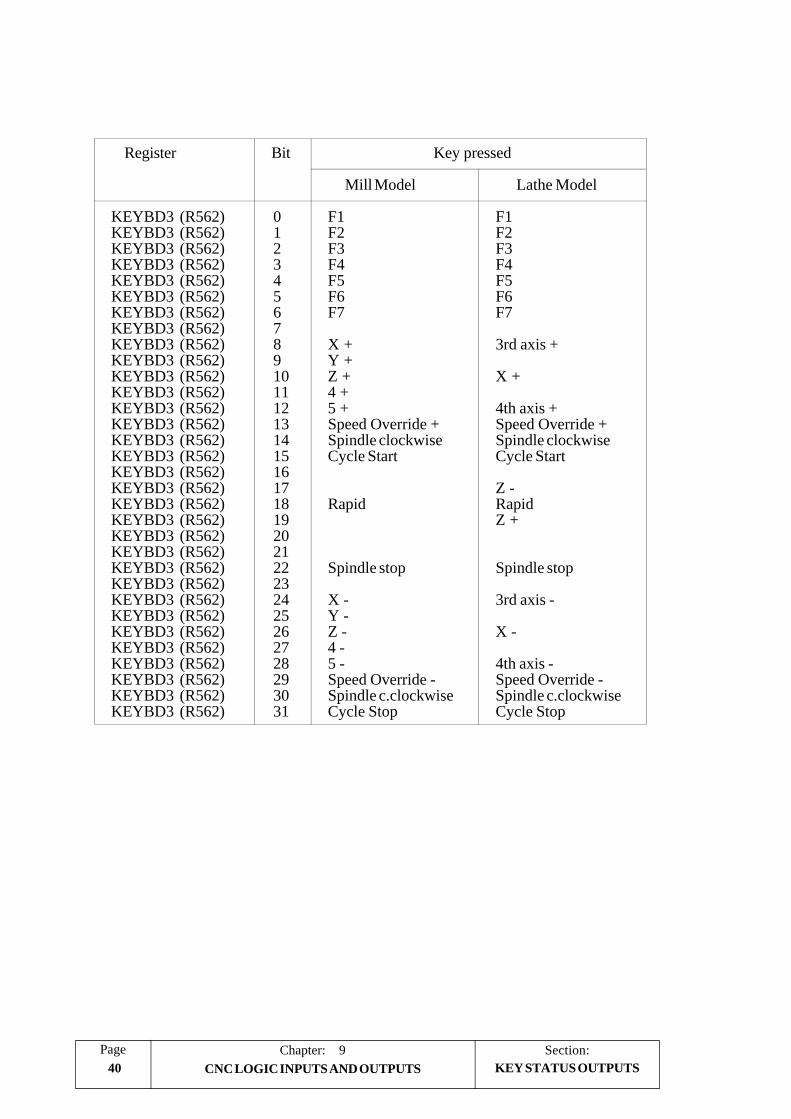
Section:Chapter: 940
Page
CNC LOGIC INPUTS AND OUTPUTS KEY STATUS OUTPUTS
Register Bit Key pressed
Mill Model Lathe Model
KEYBD3 (R562) 0 F1 F1KEYBD3 (R562) 1 F2 F2KEYBD3 (R562) 2 F3 F3KEYBD3 (R562) 3 F4 F4KEYBD3 (R562) 4 F5 F5KEYBD3 (R562) 5 F6 F6KEYBD3 (R562) 6 F7 F7KEYBD3 (R562) 7KEYBD3 (R562) 8 X + 3rd axis +KEYBD3 (R562) 9 Y +KEYBD3 (R562) 10 Z + X +KEYBD3 (R562) 11 4 +KEYBD3 (R562) 12 5 + 4th axis +KEYBD3 (R562) 13 Speed Override + Speed Override +KEYBD3 (R562) 14 Spindle clockwise Spindle clockwiseKEYBD3 (R562) 15 Cycle Start Cycle StartKEYBD3 (R562) 16KEYBD3 (R562) 17 Z -KEYBD3 (R562) 18 Rapid RapidKEYBD3 (R562) 19 Z +KEYBD3 (R562) 20KEYBD3 (R562) 21KEYBD3 (R562) 22 Spindle stop Spindle stopKEYBD3 (R562) 23KEYBD3 (R562) 24 X - 3rd axis -KEYBD3 (R562) 25 Y -KEYBD3 (R562) 26 Z - X -KEYBD3 (R562) 27 4 -KEYBD3 (R562) 28 5 - 4th axis -KEYBD3 (R562) 29 Speed Override - Speed Override -KEYBD3 (R562) 30 Spindle c.clockwise Spindle c.clockwiseKEYBD3 (R562) 31 Cycle Stop Cycle Stop

PageChapter: 10
ACCESS TO INTERNAL CNC VARIABLES 1Section:
10. ACCESS TO INTERNAL CNC VARIABLES
The PLC provides two instructions (actions) which permit to read or modify the variousinternal variables of the CNC.
CNCRD: Allows reading access to the CNC internal variables. It is programmed asfollows:
CNCRD (Variable, Register, Mark)
This instruction loads the selected PLC register with the contents of the indicated CNCvariable.
If this instruction has been executed properly, the PLC will assign a value of “0” to theindicated “error detection” Mark and “1” if otherwise.
Example: CNCRD (FEED, R150, M200)
It loads the value of the feedrate selected at the CNC when working in G94 intothe PLC register R150.
When requesting information about a non-existing variable (i.e. the position value ofa non-existing axis), this instruction will not alter the contents of R150 and it will seterror mark M200 to “1” indicating that the variable does not exist.
CNCWR: Allows writing access to internal CNC variables. It is programmed as follows:
CNCWR (Register, Variable, Mark)
This instruction loads the contents of the indicated PLC register into the selected CNCvariable.
If this instruction has been executed properly, the PLC will assign a value of “0” to theindicated “error detection” Mark and “1” if otherwise.
Example: CNCWR (R92, TIMER, M200)
Presets the timer enabled by the PLC with the value contained in Register R92.
When trying to modify the contents of a non-existing variable or assign an impropervalue to it, the selected “error mark” will be set to “1” which will indicate that thisinstruction is incorrect.
When performing an improper reading or writing request, the PLC will continue theexecution of the program unless interrupted by the programmer after having analyzedthe “error” mark defined in the instruction.

Section:ACCESS TO INTERNAL CNC VARIABLES
Chapter: 102
Page
The internal CNC variables which can be accessed by the PLC can be read-only orread-and-write variables.
Every internal CNC table (tools, tool offset, Zero offsets, etc.) has a mnemonic toidentify the fields. Use one of the following formats to access a specific variable:
* The corresponding mnemonic followed by the element number of that table.Example (TOR3):
CNCRD (TOR3, R100, M102); Assigns the R value of tool offset 3 to registerR100.
* The corresponding mnemonic and a register containing the element number of thattable. Example (TOR R222):
CNCRD (TOR R222, R100, M102); assigns to register R100 the R value of the tooloffset indicated by register R222.
The variables available at the CNC 8050 can be classified in the following way:
- Variables associated with tools.- Variables associated with zero offsets.- Variables associated with machine parameters- Variables associated with work zones- Variables associated with feedrates- Variables associated with coordinates- Variables associated with the spindle- Variables associated with local and global parameters- Other variables

PageChapter: 10
ACCESS TO INTERNAL CNC VARIABLES 3Section:
VARIABLES ASSOCIATEDWITH TOOLS
10.1 VARIABLES ASSOCIATED WITH TOOLS
These variables are associated with the tool offset table, tool table and tool magazine table,so the values which are assigned to or read from these fields will comply with the formatsestablished for these tables.
Tool offset table of the MILL model FAGOR 8050 CNC:
R,L,I,K In the units set by machine parameter "INCHES"If "INCHES"=0, in 0.0001mm. Max.: ±999999999If "INCHES"=1, in 0,00001 inch. Max or ±393700787If rotary axis, in 0.0001º. Max.:± 999999999
Tool offset table of the LATHE model FAGOR 8050 CNC:
X,Z,R,I,KIn the units set by machine parameter "INCHES"If "INCHES"=0, in 0.0001mm. Max.: ±999999999If "INCHES"=1, in 0,00001 inch. Max or ±393700787If rotary axis, in 0.0001º. Max.:± 999999999
F Integer value between 0 and 99.
Tool table for Mill model CNC:
Tool offset number 0...NT OFFSET (maximum 255)Family code If normal tool, 0 < n < 200
If special tool, 200 < n < 255Nominal life 0...65535 minutes or operations.Real life 0...99,999,99 hundredths of a minute or 99,999
operations
Tool table for lathe model CNC:
Tool offset number 0...NT OFFSET (maximum 255)Family code If normal tool, 0 < n < 200
If special tool, 200 < n < 255Nominal life 0...65535 minutes or operations.Real life 0...99,999,99 hundredths of a minute or 99,999
operations.Cutter angle In 0.00010 units up to 359.99990 degrees.Cutter width In the units set by machine parameter "INCHES"
If "INCHES"=0, in 0.0001mm. Max.: ±999999999If "INCHES"=1, in 0,00001 inch. Max or ±393700787
Cutting angle I n 0.00010 units, up to 359.99990.
Tool magazine table:
Contents of each magazine positionTool number 1 ...NTOOL (maximum 255)0 Empty-1 Cancelled
Tool position in magazinePosition number 1 ..NPOCKET (maximum 255)0 On spindle-1 Not found-2 In change position

Section:ACCESS TO INTERNAL CNC VARIABLES
Chapter: 104
Page
Read-only variables
TOOL: Returns the active tool number
CNCRD(TOOL,R100,M100); Loads register R100 with the numberof the active tool
TOD: Returns the active tool offset number
NXTOOL: Returns the next tool number, which is selected but is awaiting theexecution of M06 to be active.
NXTOD: Returns the number of the tool offset corresponding to the next tool,which is selected but is awaiting the execution of M06 to be active.
TMZPn: Returns the position occupied in the tool magazine by the indicated tool(n).
Read-and-write variables
TLFDn: This variable allows the tool offset number of the indicated tool (n) tobe read or modified in the tool table.
CNCRD(TFLD3,R100,M102); Loads register R100 with the tooloffset number of tool 3.
CNCWR(R101,TFLD3,M101); Assigns the tool offset numberindicated in register R101 to toolnumber 3.
TLFFn: This variable allows the family code of the indicated tool (n) to be reador modified in the tool table.
TLFNn: This variable allows the value assigned as the nominal life of theindicated tool (n) to be read or modified in the tool table.
TLFRn: This variable allows the value corresponding to the real life of theindicated tool (n) to be read or modified in the tool table.
TMZTn: This variable allows the contents of the indicated position (n) to be reador modified in the tool magazine table.
VARIABLES ASSOCIATEDWITH TOOLS

PageChapter: 10
ACCESS TO INTERNAL CNC VARIABLES 5Section:
Read-and-write variables of the FAGOR 8050 CNC MILL model
TORn: This variable allows the value assigned to the Radius of the indicatedtool offset (n) in the tool offset table to be read or modified.
CNCRD(TOR3,R100,M102); Loads register R100 with the Rvalue of tool offset 3.
CNCWR(R101,TOR3,M101); Assigns the value indicated inR101 to the R of tool offset 3.
TOLn: This variable allows the value assigned to the Length of the indicatedtool offset (n) to be read or modified in the tool offset table.
TOIn: This variable allows the value assigned to the wear in radius (I) of theindicated tool offset (n) to be read or modified in the tool offset table.
TOKn: This variable allows the value assigned to the wear in length (K) of theindicated tool offset (n) to be read or modified in the tool offset table.
Read-and-write variables of the FAGOR 8050 CNC LATHE model
TOXn: This variable allows reading or modifying the length value along the Xaxis assigned to the indicated tool offset (n).
CNCRD (TOX3, R100, M102); Loads R100 with the length valuealong X of the tool offset 3.
CNCWR (R101, TOX3, M101); Assigns the value indicated in R101to the length along X of the tooloffset 3.
TOZn: This variable allows reading or modifying the length value along the Zaxis assigned to the indicated tool offset (n).
TOFn: This variable allows reading or modifying the location code (F) of theindicated tool offset (n).
TORn: This variable allows reading or modifying the radius R value of theindicated tool offset (n).
TOIn: This variable allows reading or modifying the length wear value (I)along the X axis of the indicated tool offset (n).
TOKn: This variable allows reading or modifying the length wear value (K)along the Z axis of the indicated tool offset (n).
NOSEAn: This variable allows reading or modifying the cutter angle assigned tothe indicated tool (n) in the tool table.
NOSEWn: This variable allows reading or modifying the cutter width assigned tothe indicated tool (n) in the tool table.
CUTAn: This variable allows reading or modifying the cutting angle assigned to
the indicated tool (n) in the tool table.
VARIABLES ASSOCIATEDWITH TOOLS

Section:ACCESS TO INTERNAL CNC VARIABLES
Chapter: 106
Page
10.2. VARIABLES ASSOCIATED WITH ZERO OFFSETS
These variables are associated with the zero offset table, due to which the values that willbe assigned to or read from these fields will comply with the formats established for thistable.
The zero offsets, in addition to the additive offset indicated by the PLC, are G54, G55, G56,G57, G58 and G59 and
The values of each axis are given in the units set by machine parameter "INCHES".
If "INCHES"=0, in 0.0001mm. Max.: ±999999999If "INCHES"=1, in 0,00001 inch. Max or ±393700787If rotary axis, in 0.0001º. Max.:± 999999999
Although there are variables which refer to each axis, the CNC only allows those referringto the selected axes in the CNC. Thus, if the CNC controls axes X, Y, Z, U and B, it onlyallows the variables ORGX, ORGY, ORGZ,. ORGU and ORGB in the case ofORG(X-C).
Read-only variables
ORG(X-C): Returns the value of the active zero offset in the selected axis. The valueof the additive offset indicated by the PLC is not included in this value.
Read-and-write variables
ORG(X-C)n: This variable allows the value of the selected axis to be read or modifiedin the table corresponding to the indicated zero offset (n).
CNCRD(ORGX 55,R100,M102); Loads register R100 with the Xvalue of G55 in the zero offsettable.
CNCWR(R101,ORGY 54,M101); Assigns the value indicated inR101 to the Y value of G54 inthe zero offset table.
PLCOF(X-C):This variable allows the value of the selected axis to be read or modifiedin the additive zero offset table indicated by the PLC.
VARIABLES ASSOCIATEDWITH ZERO OFFSETS

PageChapter: 10
ACCESS TO INTERNAL CNC VARIABLES 7Section:
10.3 VARIABLES ASSOCIATED WITH MACHINE PARAMETERS
Variables associated with machine parameters are read-only variables.
In order to become familiar with the values returned it is advisable to consult the chapterdealing with those parameters taking into account the following indications:
Values 1/0 correspond to the parameters which are defined with YES/NO, +/- and ON/OFF.
Values regarding position and feedrate values will be given in the units set by machineparameter "INCHES".
If "INCHES"=0, in 0.0001mm. Max.: ±999999999If "INCHES"=1, in 0,00001 inch. Max or ±393700787
Values regarding the spindle (when working in M19) and rotary axes will be given in0.0001 degree units. Max.:± 999999999.
Read-only variables
MPGn: Returns the value assigned to the indicated general machine parameter(n).
CNCRD (MPG 8,R100,M102); Loads register R100 with the value ofgeneral machine parameter P8(INCHES). If mm, R100 = 0; andif inch, R100 =1.
MP(X-C)n: Returns the value assigned to the machine parameter (n) of the indicatedaxis.
CNCRD (MPY 1,R100,M102); Loads register R100 with the value ofmachine parameter P1(DFORMAT) for the Y axis whichindicates the display format forthis axis.
MPSn: Returns the value assigned to the indicated machine parameter (n) of thespindle.
MPASn: Returns the value of the indicated (n) machine parameter for theauxiliary spindle.
MPLCn: Returns the value assigned to the indicated machine parameter (n) of thePLC.
VARIABLES FOR MACHINEPARAMETERS

Section:ACCESS TO INTERNAL CNC VARIABLES
Chapter: 108
Page
10.4 VARIABLES ASSOCIATED WITH WORK ZONES
The values of the limits are given in the units set by machine parameter "INCHES".
If "INCHES"=0, in 0.0001mm. Max.: ±999999999If "INCHES"=1, in 0,00001 inch. Max or ±393700787If rotary axis, in 0.0001º. Max.:± 999999999
The status of the work zones are defined according to the following code:
0 = Disabled.1 = Enabled as no-entry zone.2 = Enabled as no-exit zone.
Read-and-write variables
FZONE: This variable permits reading or writing the status of work zone 1.
FZLO(X-C): This variable permits reading or writing the value of the lower limit ofZone 1 according to the selected axis (X-C).
FZUP(X-C): This variable permits reading or writing the value of the upper limit ofZone 1 according to the selected axis (X-C).
SZONE: This variable permits reading or writing the status of work zone 2.
SZLO(X-C): This variable permits reading or writing the value of the lower limit ofZone 2 according to the selected axis (X-C).
SZUP(X-C): This variable permits reading or writing the value of the upper limit ofZone 2 according to the selected axis (X-C).
TZONE: This variable permits reading or writing the status of work zone 3.
TZLO(X-C): This variable permits reading or writing the value of the lower limit ofZone 3 according to the selected axis (X-C).
TZUP(X-C): This variable permits reading or writing the value of the upper limit ofZone 3 according to the selected axis (X-C).
The following example shows how it is possible to define as forbidden zone forthe X axis the area between 0 and 100mm (1000000 tenths of microns).
(condition) = MOV 0 R1 = CNCWR (R1,FZLOX,M1)= MOV 1000000 R1 = CNCWR (R1,FZUPX,M1)= MOV 1 R1 = CNCWR (R1,FZONE,M1)
VARIABLESFOR WORK ZONES

PageChapter: 10
ACCESS TO INTERNAL CNC VARIABLES 9Section:
10.5 VARIABLES ASSOCIATED WITH FEEDRATES
Read-only variables
FREAL: Returns the real feedrate (taking the feedrate override % into account).Its value is given in 0.0001 mm/min. or 0.00001 inch/min. units.
FEED: Returns the active feedrate (ignoring the override) selected at the CNCwhen working in G94. This will be given in 0.0001mm/minute or0.00001 inch/minute units.
This feedrate can be indicated by program, by the PLC or DNC, and theCNC selects one of these, the one with the highest priority being thatindicated by DNC and the one with the lowest priority that indicated byprogram.
DNCF: Returns the feedrate selected by DNC, in 0.0001mm/minute or 0.00001inches/minute. If this has a value of 0 it means that it is not selected.
PRGF: Returns the feedrate selected by program, in 0.0001 mm/minute or0.00001 inches/minute units.
FPREV: Returns the active (ignoring the override) feedrate selected at the CNCwhen working in G95. This will be given in 0.0001 mm/rev. or 0.00001inches/rev units.
This feedrate can be indicated by program, by the PLC or DNC, and theCNC selects one of these, the one with the highest priority being thatindicated by DNC and the one with the lowest priority that indicated byprogram.
DNCFPR: Returns the feedrate selected by DNC, in 0.0001 mm/rev. or 0.00001inches/rev units. If this has a value of 0 it means that it is not selected.
PRGFPR: Returns the feedrate selected by program in 0.0001 mm/rev. or 0.00001inches/rev units.
VARIABLESFOR FEEDRATES

Section:ACCESS TO INTERNAL CNC VARIABLES
Chapter: 1010
Page
FRO: Returns the Feedrate Override (%) selected at the CNC. This will begiven by an integer between 0 and “MAXFOVR” (maximum 255).
This feedrate percentage may be indicated by the PLC, by DNC or fromthe front panel, and the CNC will select one of them, the order of priority(from highest to lowest) being: by program, by DNC, by PLC and fromthe front panel switch.
PRGFRO: Returns the % of the feedrate selected by program. It is given in integervalues between 0 and “MAXFOVR” (maximum 255). A value of 0means that it is not selected.
DNCFRO: Returns the feedrate, in mm/minute or inches/minute, which is selectedby DNC. If this has a value of 0 it means that it is not selected.
CNCFRO: Returns the % of feedrate selected from the front panel knob.
Read-and-write variables
PLCF: This variable allows reading or modifying the feedrate selected by PLC.It is given in 0.0001 mm/min. or 0.00001 inch/min units. A value of 0means that it is not selected.
PLCFPR: This variable allows reading or modifying the feedrate selected by PLC.It is given in 0.0001 mm/rev. or 0.00001 inch/rev units. A value of 0means that it is not selected.
PLCFRO: This variable allows reading or modifying the % of feedrate selected byPLC. A value of 0 means that it is not selected.
VARIABLESFOR FEEDRATES

PageChapter: 10
ACCESS TO INTERNAL CNC VARIABLES 11Section:
10.6 VARIABLES ASSOCIATED WITH POSITION COORDINATES
The coordinate values of each axis are given in the units set by machine parameter"INCHES".
If "INCHES" = 0, in 0.0001 mm. Max. ±999999999If "INCHES" = 1, in 0.00001 inch. Max. ±39370078If rotary axis, in 0.0001º. Max. ±999999999
Read-only variables
POS(X-C): Returns the real position value of the selected axis referred to machinereference zero (home).
On the Lathe model FAGOR 8050 CNC, the coordinates of each axisare shown in either radius or diameter depending on the setting ofmachine parameter "DFORMAT".
TPOS(X-C): Returns the theoretical position value (real + following error) of theselected axis referred to machine reference zero (home).
On the Lathe model FAGOR 8050 CNC, the coordinates of each axisare shown in either radius or diameter depending on the setting ofmachine parameter "DFORMAT".
FLWE(X-C): Returns the following error of the selected axis, in 0.0001mm or0.00001 inch units .
DEFLEXDEFLEYDEFLEZ: These variables can only be used on the Mill model FAGOR 8050
CNC. They return the amount of deflection obtained at the time by theRenishaw probe SP2 on each axis X, Y, Z.
Read-and-write variables
DIST(X-C): These variables allow the distance travelled by the selected axis to beread or modified. This value is accumulative and is very useful when itis required to perform an operation which depends on the distancetravelled by the axes, for example: in their lubrication.
The CNC will set this value to 0 when changing the software versionor when a checksum error occurs.
VARIABLES FOR POSITIONCOORDINATES

Section:ACCESS TO INTERNAL CNC VARIABLES
Chapter: 1012
Page
10.7 VARIABLES ASSOCIATED WITH THE SPINDLE
Read-only variables
SREAL: Returns the real spindle turning speed. This will be in 0.0001 rev./min. units.
SPEED: Returns the spindle turning speed which is selected at the CNC. Thiswill be given in 0.0001 rev./min. units.
This turning speed can be indicated by program, by the PLC or DNC,and the CNC selects one of these, the one with the highest priority beingthat indicated by DNC and the one with the lowest priority that indicatedby program.
DNCS: Returns the turning speed in 0.0001 rev./min. units selected by DNC.If this has a value of 0 it means that it is not selected.
PRGS: Returns the turning speed in 0.0001 rev./min. units selected by program.
CSS This variable can only be used on FAGOR 8050 CNC LATHEmodels. It returns the constant surface speed selected at the CNC. itsvalue will be in meters/min. or feet/min. depending on the setting ofmachine parameter "INCHES" (=0 or =1 respectively).
This constant surface speed can be indicated by program, PLC or viaDNC. The CNC will select one of them. The DNC has the highestpriority and the program the lowest.
DNCCSS This variable can only be used on FAGOR 8050 CNC LATHEmodels. It returns the constant surface speed selected via DNC. Its valueis given in meters/min. or feet/min. A value of “0” means that it is notselected.
PRGCSS This variable can only be used on FAGOR 8050 CNC LATHEmodels. It returns the constant surface speed selected by program. Itsvalue is given in meters/min. or feet/min.
SSO: Returns the Override (%) of the spindle turning speed which is selectedat the CNC. This will be given by an integer between 0 and“MAXSOVR” (maximum 255).
This spindle turning speed percentage may be indicated by the PLC, byDNC or from the front panel, and the CNC will select one of them, theorder of priority (from highest to lowest) being: by program, by DNC,by PLC and from the front panel.
VARIABLES ASSOCIATEDWITH THE SPINDLE

PageChapter: 10
ACCESS TO INTERNAL CNC VARIABLES 13Section:
PRGSSO: It returns the percentage of the spindle turning speed selected byprogram. This will be given by an integer between 0 and “MAXSOVR”(maximum 255). If this has a value of 0 it means that it is not selected.
DNCSSO: Returns the spindle turning speed percentage which is selected byDNC. If this has a value of 0 it means that it is not selected.
CNCSSO: Returns spindle turning speed percentage which is selected from thefront panel.
SLIMIT: Returns the value established for the spindle turning speed limit whichis selected at the CNC. This will be in 0.0001 rev./min. units.
This limit can be indicated by program, by the PLC or DNC, and theCNC selects one of these, the one with the highest priority being thatindicated by DNC and the one with the lowest priority that indicated byprogram.
If this limit has not been defined, this variable will return a value of 0.
DNCSL: Returns the spindle turning speed limit selected by DNC in 0.0001 rev./min. units. If this has a value of 0 it means that it is not selected.
PRGSL: Returns the spindle turning speed limit which is selected by program in0.0001 rev./min. units.
POSS: Returns the spindle real position value, when it is in closed loop (M19).Its value will be given in 0.0001 degree units between ±999999999.
If the spindle is not in closed loop (M19), this variable will return a valueof 0.
RPOSS: Returns the spindle real position value when operating in closed loop(M19) and as rollover. Its value will be given in 0.0001 degree unitsbetween 0 and 360º,
TPOSS: Returns the spindle theoretical position value (real + following error)when it is in closed loop (M19). Its value will be given in 0.0001 degreeunits between ±999999999.
When not in M19, this variable returns a "0" value.
RTPOSS: Returns the spindle theoretical position value (real + following error)when operating in closed loop (M19) and as rollover. Its value will begiven in 0.0001 degree units between 0 and 360º.
FLWES: Returns the spindle following error when it is operating in closed loop(M19).
When the spindle is not in closed loop (M19), this variable will returna value of "0".
VARIABLES ASSOCIATEDWITH THE SPINDLE

Section:ACCESS TO INTERNAL CNC VARIABLES
Chapter: 1014
Page
Read-and-write variables
PLCS: This variable allows reading or modifying the spindle speed in 0.0001rev./min. units. A value of “0” means that it is not selected.
PLCCSS: This variable can only be used on FAGOR 8050 CNC LATHEmodels. It allows reading or modifying the constant surface speedselected by PLC. Its value is given in meters/min. or feet/min.
PLCSSO: It allows reading or modifying the spindle turning speed percentagewhich is selected by PLC. If this has a value of 0 it means that it is notselected.
PLCSL: It allows reading or modifying the spindle turning speed limit selectedby PLC in 0.0001 rev./min units. If this has a value of 0 it means that itis not selected.
VARIABLES ASSOCIATEDWITH THE SPINDLE

PageChapter: 10
ACCESS TO INTERNAL CNC VARIABLES 15Section:
VARIABLES FOR ARITH-METIC PARAMETERS
10.8 VARIABLES ASSOCIATED TO GLOBAL AND LOCALARITHMETIC PARAMETERS
The FAGOR 8050 CNC offers two types of general purpose variables, local parameters P0thru P25 and global parameters P100 thru P299.
It is possible to assign local parameters to more than one subroutine. Up to 6 nesting levelsof the local parameters are possible within the 15 nesting levels for the subroutines.
Therefore, each time a local parameter must be referred to, it is necessary to indicate itscurrent nesting level.
Local and global parameters may be assigned a value within +2147483647.
When reading the value of one of these parameters by means of functions GUP and LUPthe obtained value will always be an integer (dropping the decimals if it has them). If theparameter value is greater than +2147483647 the variable will return this maximum value.
Read-and-write variables
GUP n: This variable allows reading or modifying the indicated global parameter(n) (P100-P299).
CNCRD (GUP 155, R100, M102); Loads register R100 with thevalue of global parameter P155.
CNCWR (R101, GUP 155, M101); Assigns the value in registerR101 to global parameter P155.
LUP a b: This variable allows reading or modifying the indicated local parameter(b) (P0-P25) corresponding to a nesting level (a).
CNCRD (LUP 3 15, R100, M102); Loads register R100 with thevalue of local parameter P15corresponding to nesting level3.
CNCWR (R101, LUP 2 15, M101);Assigns the value in R101 to localparameter P15 correspondingto nesting level 2.

Section:ACCESS TO INTERNAL CNC VARIABLES
Chapter: 1016
Page
OTHER VARIABLES
10.9 OTHER VARIABLES
Read-only variables
OPMODE: Returns the code corresponding to the selected operating Mode.
0 = Main menu.
10 = Automatic execution.11 = Single block execution.12 = MDI in EXECUTION13 = Tool inspection
20 = Theoretical path movement simulation21 = G functions simulation22 = G, M, S and T functions simulation23 = Simulation with movement on main plane24 = Simulation with rapid movement
30 = Normal editing31 = User editing32 = TEACH-IN editing33 = Interactive edior34 = Profile editor
40 = Movement in continuous JOG41 = Movement in incremental JOG42 = Movement with electronic handwheel43 = HOME search in JOG44 = Position preset in JOG45 = Tool calibration46 = MDI in JOG47 = JOG user operation
50 = Zero offset table51 = Tool Offset table52 = Tool table53 = Tool magazine table54 = Global parameter table55 = Local parameter table
60 = Utilities
70 = DNC
80 = Editing PLC files81 = Compiling PLC program82 = PLC monitoring83 = Active PLC messages84 = Active PLC pages (screens)85 = Save PLC program86 = Restore PLC program87 = PLC usage maps88 = PLC statistics

PageChapter: 10
ACCESS TO INTERNAL CNC VARIABLES 17Section:
90 = Graphic Editor
100 = General machine parameter table101 = Axis machine parameter tables102 = Spindle machine parameter tables103 = Serial port machine parameter tables104 = PLC machine parameter table105 = M function table106 = Leadscrew and cross compensation table
110 = Diagnosis: configuration111 = Diagnosis: hardware test112 = Diagnosis: RAM memory test113 = Diagnosis: EPROM memory test (checksums)114 = User diagnosis
PRGN: Returns the program number which is being executed. Should none beselected, a value of -1 is returned.
BLKN: Returns the label number of the block being executed or that of the lastblock executed. If none, it returns -1.
GGSA: It returns the status of functions G00 thru G24. The status of each oneof these functions will be given in the 25 least significant bits and it willbe indicated by a 1 when active and a 0 when not active or when notavailable in the current software version.
G G G G G G G G00 00 00 00 00 00 00 24 23 22 21 20 02 01 00
LSB
CNCRD (GGSA, R100, M102); Loads register R100 with the statusof functions G00 thru G24.
GGSB: It returns the status of functions G25 thru G49. The status of each oneof these functions will be given in the 25 least significant bits and it willbe indicated by a 1 when active and a 0 when not active or when notavailable in the current software version.
G G G G G G G G00 00 00 00 00 00 00 49 48 47 46 45 27 26 25
LSB
OTHER VARIABLES

Section:ACCESS TO INTERNAL CNC VARIABLES
Chapter: 1018
Page
GGSC: It returns the status of functions G50 thru G74. The status of each oneof these functions will be given in the 25 least significant bits and it willbe indicated by a 1 when active and a 0 when not active or when notavailable in the current software version.
G G G G G G G G 00 00 00 00 00 00 00 74 73 72 71 70 52 51 50
LSB
GGSD: It returns the status of functions G75 thru G99. The status of each oneof these functions will be given in the 25 least significant bits and it willbe indicated by a 1 when active and a 0 when not active or when notavailable in the current software version.
G G G G G G G G 00 00 00 00 00 00 00 99 98 97 96 95 77 76 75
LSB
PLANE: Returns data on the abscissa axis (bits 4 to 7) and the ordinate axis (bits0 to 3) of the active plane in 32 bits and in binary.
.... .... .... .... .... .... 7654 3210LSB
Ordinate axis
Abscissa axis
The axes are coded in 4 bits and indicate the axis number (from 1 to 6)according to the programming order.
Example: If the CNC controls the X,Y,Z,U,B,C axes and the ZX plane(G18) is selected.
CNCRD (PLANE, R100, M102); Loads register R100 with He-xadecimal value $31.
0000 0000 0000 0000 0000 0000 0011 0001
LSB
Abscissa axis = 3 (0011) --> Z axis
Ordinate axis = 1 (0001) --> X axis
OTHER VARIABLES

PageChapter: 10
ACCESS TO INTERNAL CNC VARIABLES 19Section:
LONGAX: This variable can only be used on the Mill model FAGOR8050 CNC.It returns the number (1 to 6) according to the programming ordercorresponding to the longitudinal axis. This will be the one selected withthe G15 function and by default the axis perpendicular to the activeplane, if this is XY, ZX or YZ.
Example: If the CNC controls the X, Y, Z, U, B, C axes and the U axisis selected.
CNCRD (LONGAX, R100, M102); Loads register R100 with avalue of 4 (4th axis = U).
MIRROR: Returns in the 6 least significant bits of the 32-bit word, the status ofthe mirror image of each axis, 1 in the case of being active and 0 ifnot.
LSB
Axis 1Axis 2Axis 3Axis 4Axis 5
Axis 6
The axis name corresponds to the number (1 to 6) according to theprogramming order for them.
Example: If the CNC controls axes X, Y, Z, U, B, C.Axis 1=X, Axis2=Y, Axis3=Z, Axis4=U, Axis5=B, Axis6=C.
SCALE: Returns the active general scaling factor multiplied by 10000.
SCALE(X-C):Returns the specific scaling factor of the indicated axis (X-C) multipliedby 10000.
ORGROT: Returns, in 0.0001 degree units, the rotation angle of the coordinatesystem selected with the G73 function.
PRBST: Returns the status of the probe.
0 = The probe is not touching the part.1 = The probe is touching the part.
CLOCK: Returns the time in seconds indicated by the system clock. Possiblevalues 0...4294967295.
OTHER VARIABLES

Section:ACCESS TO INTERNAL CNC VARIABLES
Chapter: 1020
Page
TIME: Returns the time in hours-minutes-seconds format.
CNCRD (TIME, R100, M102); Loads register R100 hh-mm-ss.For example if the time is: 18h22m 34sec. R100 = 182234.
DATE: Returns the date in year-month-day format.
CNCRD (DATE, R100, M102); Loads register R100 with year-month-day. For example: if thedate is April 25th 1992, R100 =920425.
CYTIME: Returns in hundredths of a second the time elapsed in making the partnot counting the time period when the program execution might havebeen stopped. Possible values 0...4294967295
The CNC will consider the execution of the program finished afterexecuting the last block of the program or after executing a blockcontaining an M02 or M30 miscellaneous function.
FIRST: Indicates whether it is the first time that a program has been run or not.It returns a value of 1 if it is the first time and 0 if not.
A first-time execution is considered as being one which is done:
After turning on the CNC.After pressing the “Shift-Reset” keys.Every time a new program is selected.
ANAIn: Returns the value (+/-5 Volts) in 0.0001 mV units,of the indicatedanalog input (n), it being possible to select one among the eight (1...8)analog inputs.
CNCERR Returns the Error code active at the CNC. If none, it returns “0”.
DNCERR Returns the Error code generated via DNC. If none, it returns “0”.
OTHER VARIABLES

PageChapter: 10
ACCESS TO INTERNAL CNC VARIABLES 21Section:
Read-and-write variables
TIMER: This variable allows reading or modifying the time, in seconds, indicatedby the clock enabled by the PLC. Possible values 0...4294967295
The CNC will set this value to 0 when changing the software versionor when a checksum error occurs.
PARTC: The CNC has a part counter whose count increases every time M30 orM02 is executed and this variable allows its value to be read or modified.This value will be between 0 and 4294967295
The CNC will set this value to 0 when changing the software versionor when a checksum error occurs.
KEY: This variable allows reading the last accepted keystroke or simulatingthe CNC keyboard assigning the desired key code to it.
CNCRD (KEY,R100,M102); Loads register R100 with the valueof the last key accepted.
To simulate the CNC keyboard from the PLC, follow these steps:
R111 = 1 R110 = 0
CNCWR (R111,KEYSRC,M101); Indicates to the CNC that onlykeystrokes coming from thePLC must be processed (CNCkeyboard inhibited).
CNCWR (R101, KEY, M101); Indicates to the CNC that thekey corresponding to the codecontained in R101 has beenpressed.
CNCWR (R110,KEYSRC,M101); Process only keystrokescoming from the CNC (CNCkeyboard enabled).
OTHER VARIABLES

Section:ACCESS TO INTERNAL CNC VARIABLES
Chapter: 1022
Page
OTHER VARIABLES
KEYSRC: This variable allows reading or modifying the source of keystrokes,possible values being:
0 = Keyboard1 = PLC2 = DNC
The CNC only allows modification of this variable (by the PLC) if it isset to “0” or “1”.
Once the keystroke simulation is finished, it is advisable to re-enable theCNC keyboard in order to be able to access the various operating modesof the CNC.
The CNC will assign a value of 0 to this variable on power-up and afterpressing SHIFT, RESET.
ANAOn: This variable allows the required analog output (n) to be read ormodified. The value assigned will be expressed in 0.0001 volt units andwithin +/-10 Volts.
The analog outputs which are free among the eight (1..8) available at theCNC may be modified, the corresponding error being displayed if anattempt is made to write in one which is occupied.

PageChapter: 11
AXES CONTROLLED FROM THE PLC
Section:1
11. AXES CONTROLLED FROM THE PLC
The PLC offers the action: CNCEX which allows to send commands to the CNC in orderfor it to execute movements on one or several axes.
The programming format for this action is:
CNCEX (ASCII Block , Mark)
By means of this action, the PLC will send to the CNC the command indicated in the "ASCIIBlock" for it to execute it.
If the "ASCII Block" has been accepted by the CNC, the PLC will set the indicated Markto "0" and to "1" if otherwise.
The CNC only indicates that the "ASCII block" has been accepted. It is up to the operatorto check whether the command has been executed by the CNC or not.
Example: CNCEX (G1 U125 V300 F500, M200)
Sends to the CNC the command: G1 U125 V300 F500 so it carries out a linearinterpolation between the U and V axes at a feedrate of F500 and being U125V300 the end point.

Section:Chapter: 112
PageAXES CONTROLLED FROM THE PLC CONSIDERATIONS
11.1 CONSIDERATIONS
Set-up
Each axis machine parameter "AXISTYPE" must be set properly indicating whetherthat axis is controlled by the CNC or from the PLC.
An axis cannot be controlled both from the CNC and from the PLC at the same time.
PLC Execution channel
The CNC offers a parallel execution channel to execute commands received from thePLC. This channel will have its own history and it permits the execution of blocksprogrammed from the PLC regardless of the operating mode being selected at the CNCat the time.
When the CNC receives a command from the PLC and it is executing another commandreceived previously, it will store it in an internal buffer and it will execute it as soon asthe previous one is done.
The internal buffer can store up to three blocks received from the PLC besides the onecurrently in execution.
Data transfer
If when executing at the PLC the action "CNCEX (ASCII Block, Mark)", the CNCdetects that the contents of the ASCII block being received is erroneous, it will set theindicated Mark to "1". The PLC program will keep executing while it is up to theprogrammer to check whether the function was executed correctly or not.
The CNC considers the contents of the ASCII block incorrect in the followinginstances:
* When the syntax is incorrect.
* When programming a not-permitted preparatory function (G code).
* When programming an auxiliary function M, S, T or tool offset D.
* When programming a high level language block.
* When the axis to be moved cannot be controlled from the PLC.
* When the internal buffer for PLC command storage is full.

PageChapter: 11
AXES CONTROLLED FROM THE PLC
Section:3
Errors during execution
When the CNC detects an execution error in one of the two execution channels (forexample, travel limit overrun), it will show the corresponding error code.If it must also stop the movement of the axes and the spindle rotation, the CNC will stopthe movement of all the axes regardless of whether they are controlled from the CNCor the PLC.
Also, if the detected error stops the program execution, the CNC will stop the executionof both channels and each one of them will act as follows:
CNC channel Once the cause of the error has been removed, select again the executionor simulation mode and continue with the program execution.
PLC channel The PLC program does not stop and continues running.
The commands sent by means of action "CNCEX" will not beexecuted until removing the cause of the error.
Once the cause of the error removed, the CNC will execute all thenew commands sent by the PLC.
To know from the PLC program whether any CNC error is active,this information can be requested by accessing the internal CNCvariable "CNCERR". This variable indicates the error number beingactive at the CNC and if none is active, it returns a 0 value.
CONSIDERATIONS

Section:Chapter: 114
PageAXES CONTROLLED FROM THE PLC
11.2 BLOCKS WHICH CAN BE EXECUTED FROM THE PLC
The ASCII block to be sent to the CNC by means of the action CNCEX to be executedin the PLC execution channel must be written in the CNC's own programming format.
An ASCII block may contain preparatory functions, axis position and feedrate values. Onthe other hand, it may not contain any auxiliary functions M, S, or T; nor tool offset D aswell as any high level language blocks.
The information which an ASCII block may contain is the following:
Preparatory functions
The preparatory functions which can be used in the PLC execution channel are thefollowing:
G00: Rapid traversG01: Linear interpolationG02: Clockwise circular (helical) interpolationG03: Counter-clockwise circular (helical) interpolationG04: DwellG05: Round cornerG06: Arc center in absolute coordinatesG07: Square cornerG08: Arc tangent to previous path.G09: Arc defined by three pointsG16: Main plane selection by two addressesG50: Controlled corner roundingG52: Movement until making contactG53: Programming with respect to machine reference zero (home)G70: Inch programmingG71: Metric programmingG74: Home searchG75: Probing move until touchingG76: Probing move while touchingG90: Absolute programmingG91: Incremental programmingG92: PresetG94: Feedrate in millimeters (inches) per minute.G95: Feedrate in millimeters (inces) per revolution.
All these functions must be programmed as indicated in the programming manual andall their related notes in the manual are valid.
Axes position values (coordinates)
Only those axes set by means of machine parameter "AXISTYPE" for each axis as tobe controlled by the PLC can be mentioned.
The position values of these axes, which can be either linear or rotary, can beprogrammed in either cartesian or polar coordinates.
BLOCKS EXECUTABLEFROM THE PLC

PageChapter: 11
AXES CONTROLLED FROM THE PLC
Section:5
These coordinates can also be defined via parametric programming using any globalarithmetic parameters (P100 thru P299)
When using parametric programming, it is recommended to previously assign a valueto the corresponding global parameter by means of the instruction: CNCWR.
Example:
...... = MOV 150 R1 Assigns a value of 150 to register R1
...... = CNCWR (R1, GUP200, M100) Assigns the value of R1 to parameterP200, (P200=150)
...... = CNCEX (G90 G1 U P200, M100) Requests the CNC to execute thecommand: G90 G1 U150. The Uaxis will go to position 150.
Axes feedrate
The programming format for the axis feedrate (F5.5) depends on the function (G94 orG95) and on the work units selected for this execution channel.
* If G94, in mm/min. or inches/min.* If G95, in mm/rev or inches/rev.
It must be borne in mind that this feedrate depends on the actual spindle rpm which isin the main execution channel.
If the move corresponds to a rotary axis, the CNC will assume the feedrate to beprogrammed in degrees/min.
Blocks programmed in high-level language
The programming of high-level language blocks from the PLC has the followingrestrictions:
* The programmed blocks can only operate with global arithmetic parameters.* The "PCALL" and "MCALL" instructions cannot be used because they work with
local arithmetic parameters.* Up to 5 nesting levels are permitted for standard subroutines. Neither parametric nor
global subroutines may be used.
Example in mm: Move the W axis to the position indicated by register R101.
Since the PLC works with 32-bit integers, the value contained in R2 is given inten-thousandths of a millimeters (tenths of a micron ).
CNCWR (R101, GUP 155, M101) Assigns the value of R101 to globalparameter P155
CNCEX (P155=P155/10000) Converts the value of P155 to mm.CNCEX (G1 WP155 F2000) Moves the W axis.
BLOCKS EXECUTABLEFROM THE PLC

Section:Chapter: 116
PageAXES CONTROLLED FROM THE PLC
11.3 CONTROL OF THE PLC PROGRAM FROM THE CNC
The section of the PLC program regarding the "axes controlled from the PLC" can becontrolled from the CNC itself.
To do this, the inputs, outputs, marks, registers, timers or counters of the PLC itself are used.
The CNC has the following PLC related variables to read or change the status of the selectedresource.
PLCI To read or modify up to 32 PLC inputs.PLCO To read or modify up to 32 PLC outputs.PLCM To read or modify up to 32 PLC marks (internal relays).PLCR To read or modify the status of a register.PLCT To read or modify the count of a timer.PLCC To read or modify the count of a counter.
With these variables, the desired values will be assigned, in the part-program of the CNC,to the PLC resources used in the communication. The setting of these values will be carriedout whenever an axis or axes are to be controlled from the PLC.
In turn, the PLC program must check the status of such resources and when detecting thatone of them is activated, it must execute the corresponding section of the PLC program.
It is also possible to transfer data from the CNC to the PLC via global and local arithmeticparameters. The PLC has the following variables related to those CNC parameters:
GUP To read or modify a global parameter of the CNC.LUP To read or modify a local parameter of the CNC.
Example:
The "U" axis is controlled by the PLC and we want to command it from any part-program of the CNC in such way that we could select the type of move (G00 or G01),the positioning coordinate and the feedrate for that move.
In order to command it from any part-program, it is convenient to have in a subroutinethe section of the CNC program allowing the data transfer with the PLC.
This example uses subroutine SUB1 and, for data exchange, it uses global CNCparameters.
P100 Type of move. If P100 = 0 ==> G00; If P100 = 1 ==> G01.
P101 "U" axis positioning coordinate.
P102 Feedrate. It only makes sense when moving in G01.
PLC PROGRAM CONTROLFROM THE CNC

PageChapter: 11
AXES CONTROLLED FROM THE PLC
Section:7
To indicate to the PLC that it must execute this move, it activates the following PLCresource:
M1000 Command to begin movement.
Any part-program of the CNC may contain a block of the type:
(PCALL 1, G1, U100, F1000)
This block calls subroutine SUB1 and it transfers the local parameters G, U andF with the following information:
G Type of movementU "U" axis positioning coordinateF Feedrate for the movement
Subroutine SUB1 can be programmed as follows:
( SUB 1)( P100 = G, P101 = U, P102 = F ) ;Data transfer to global parameters( PLCM1000 = PLCM1000 OR 1 ) ;Execution command for the PLC.( RET )
The PLC program, in turn, will have to contain the following instructions:
M1000 = CNCEX ( G90 GP100 UP101 FP102, M111) ;When markM1000 is active, it sends the indicated blockto the CNC
NOT M111 = RES M1000 ;If the CNC accepts this block, it resetsmark M1000.
PLC PROGRAM CONTROLFROM THE CNC

PageChapter: 12
PLC PROGRAMMING EXAMPLE 1
12. PLC PROGRAMMING EXAMPLE
It is a three-axes machine (X, Y, Z) having a spindle with two speed ranges.
The PLC, besides controlling the 3 axes and the spindle, is in charge of lubricating the axes as well as turningthe coolant on and off.
CNC CONFIGURATION
Module Device Select Inputs Outputs
CPU 1AXES 2 I1 - I40 O1 - O24INPUTS-OUTPUTS (1) 3 I65 - I128 O33 - O64INPUTS-OUTPUTS (2) 4 I129 - I192 O65 - O96INPUTS-OUTPUTS (3) 5 I193 - I256 O97 - O128
Atention:Input I1 is the emergency input of the CNC and must be supplied with 24V. Regardlessof how it is treated by the PLC program, this signal is processed directly by the CNC atall times.
Output O1 is normally at 24V, high logic level, and it is set low, 0V, whenever an ALARMor an ERROR occurs at the PLC output O1.
Inputs I41 through I64 and outputs O25 through O32 are not physically connected to theoutside world.

Page Chapter: 12
PLC PROGRAMMING EXAMPLE2
DEFINITION OF SYMBOLS (mnemonics)
It is a possible to associate a symbol (name) to any PLC resource. It may have up to 8characters so long as the name does not coincide with any of the reserved instructions. Itmay not contain the following characters: blank-space " ", equal sign "=", parenthesis "("or ")", comma "," or semi-colon ";".
These symbols or names must always be defined at the beginning of the program. Duplicatesymbols are not allowed; but, one resource may have more than one symbol.
For better clarification, the symbols used in this program are grouped by subjects.
----- Symbols used in : Basic and necessary programming -----
DEF I-EMERG I1 External emergency inputDEF I-CONDI I10 Conditional mode. The CNC interrupts part-program execution when ex-
ecuting auxiliary function M01DEF SERVO-OK I11 The servo drives are O.K.DEF O-EMERG O1 Emergency output. It must be normally high
----- Symbols used in: Treatment of the axis overtravel limit switches -----
DEF I-LIMTX1 I12 X axis positive overtravel limit switchDEF I-LIMTX2 I13 X axis negative overtravel limit switchDEF I-LIMTY1 I14 Y axis positive overtravel limit switchDEF I-LIMTY2 I15 Y axis negative overtravel limit switchDEF I-LIMTZ1 I16 Z axis positive overtravel limit switchDEF I-LIMTZ2 I17 Z axis negative overtravel limit switch
----- Symbols used in: Treatment of the machine reference (home) switches -----
DEF I-REF0X I18 X axis home switchDEF I-REF0Y I19 Y axis home switchDEF I-REF0Z I20 Z axis home switch
----- Symbols used in: Treatment of M, S, T functions -----
DEF M-03 M1003 Auxiliary mark. Indicates that M03 must be executedDEF M-04 M1004 Auxiliary mark. Indicates that M04 must be executedDEF M-08 M1008 Auxiliary mark. Indicates that M08 must be executedDEF M-41 M1041 Auxiliary mark. Indicates that M41 must be executedDEF M-42 M1042 Auxiliary mark. Indicates that M42 must be executed
----- Symbols used in: Lubrication treatment -----
DEF I-LUBING I21 Operator request to lubricate the ways of the machineDEF O-LUBING O10 Ways lubrication output
----- Symbols used in: Coolant treatment -----
DEF I-COOLMA I22 The coolant is controlled by the operator. Manual modeDEF I-COOLAU I23 The CNC controls the the coolant. Automatic modeDEF O-COOL O11 Coolant output

PageChapter: 12
PLC PROGRAMMING EXAMPLE 3
----- Symbols used in: Spindle turning control -----
DEF O-S-ENAB O12 Spindle enable output
----- Symbols used in: Treatment of the spindle speed range change -----
DEF O-RANGE1 O13 Move gears to select range 1DEF O-RANGE2 O14 Move gears to select range 2DEF I-RANGE1 I24 Indicates that Range 1 is selectedDEF I-RANGE2 I25 Indicates that Range 2 is selected
----- Symbols used in: Keyboard simulation -----
DEF I-SIMULA I26 The operator requests the simulation of program P12DEF SENDKEY M1100 Indicates that the code of a key is to be sent out to the CNCDEF KEYCODE R55 Indicates the code of the key to be simulatedDEF LASTKEY R56 Indicates which is the last key accepted by the CNCDEF SENTOK M1101 Indicates that the key code has been sent correctlyDEF KEYBOARD R57 Used to indicate to the CNC the source of the keysDEF CNCKEY 0 Used to indicate that the keys come from the CNC keyboardDEF PLCKEY 1 Used to indicate that the keys come from the PLC
DEF MAINMENU $FFF4 Code of the "MAIN MENU" keyDEF SIMULATE $FC01 Code of the "SIMULATE" key (F2)DEF KEY1 $31 Code of the "1" keyDEF KEY2 $32 Code of the "2" keyDEF ENTER $0D Code of the "ENTER" keyDEF THEOPATH $FC00 Code of the "THEORETICAL PATH" key (F1)DEF START $FFF1 Code of the "START" key

Page Chapter: 12
PLC PROGRAMMING EXAMPLE4
FIRST CYCLE MODULE
CY1
( ) = ERA O1 256 = ERA C1 256 = ERA T1 256 = ERA R1 256 = ERA M1 2000= ERA M4000 4127 = ERA M4500 4563 = ERA M4700 4955
Initializes all PLC resources to low logic level "0"
( ) = TG1 2 120000 Initializes the timer which controls the lubrication of the machine ways on power-up.This lubrication lasts 2 minutes.
( ) = TG2 4 3600000 Initializes the timer which controls the amount of time the axes are moving before theyare lubricated. This lubrication lasts 5 minutes and it takes place after the axes have beenmoving for 1 hour.
END
MAIN MODULE
PRGREA
----- Basic and necessary programming -----
( ) = /STOP Permission to execute the part-program= /FEEDHOL Permission to move the axes= /XFERINH Permission to execute the next block
I-EMERG AND (rest of conditions) = /EMERGENIf the external emergency input is activated or any other emergency occurs, the general logicinput /EMERGEN of the CNC. When there is no emergency, this signal must remain high.
/ALARM AND CNCREADY = O-EMERGThe emergency output, O1, of the PLC (O-EMERG) must be normally highIf an alarm or emergency is detected at the CNC (/ALARM) or a problem was detected whenpowering the CNC up (CNCREADY), the emergency output O-EMERG must be broughtlow
I-CONDI = M01STOPWhen the operator selects the conditional mode (I-CONDI), the CNC general logic inputM01STOP must be activated. It interrupts the program when executing M01
START AND (rest of conditions) = CYSTARTWhen the cycle START key is pressed, the CNC activates the general logic output START.The PLC must check that the rest of the conditions (hydraulic, safety devices, etc.) are metbefore setting the general input CYSTART high in order to start executing the program
SERVO-OK AND NOT LOPEN = SERVO1ON = SERVO2ON = SERVO3ONIf the servo drives are OK and the CNC does not detect any errors in the positioning loopof the axes (LOPEN), the positioning loop must be closed on all axes. Axis logic inputs ofthe CNC: SERVO1ON, SERVO2ON, SERVO3ON.

PageChapter: 12
PLC PROGRAMMING EXAMPLE 5
----- Treatment of the axis overtravel limit switches -----
I-LIMTX1 = LIMIT+1I-LIMTX2 = LIMIT-1I-LIMTY1 = LIMIT+2I-LIMTY2 = LIMIT-2I-LIMTZ1 = LIMIT+3I-LIMTZ2 = LIMIT-3
----- Treatment of the machine reference (home) switches -----
I-REF0X = DECEL1I-REF0Y = DECEL2I-REF0Z = DECEL3
----- Message treatment -----
The PLC allows displaying the corresponding PLC message at the CNC screen by activatingmarks MSG1 through MSG128,. This text must be previously edited at the PLC messagetable.
The following example shows how to generate a message to remind the operator to homethe axes after powering the machine up.
(MANUAL OR MDI OR AUTOMAT) AND NOT (REFPOIN1 AND REFPOIN2 AND REFPOIN3)= MSG5
The message (MSG5) appears in the JOG, MDI or Automatic modes and only when the axesof the machine have not been referenced (homed). The CNC logic outputs "REFPOIN"indicate that the axes have been homed.
----- Error treatment -----
The PLC permits displaying the corresponding error message on the CNC screen byactivating marks ERR1 through ERR64 as well as interrupting the CNC program executionstopping the axes and the spindle. The activation of any of these marks does not activatethe external CNC Emergency output.
Because the PLC program is not interrupted by these marks, it is advised to make it possibleto change their status via accessible external inputs; otherwise, the CNC will keep receivingthe same error at every PLC scan (cycle) thus preventing access to any PLC mode.
The text associated to the error message must be previously edited at the PLC error table.
The next example shows how to generate the X axis overtravel limit overrun error when oneof the overtravel limit switches is pressed.
NOT I-LIMTX1 OR NOT I-LIMTX2 = ERR10

Page Chapter: 12
PLC PROGRAMMING EXAMPLE6
----- Treatment of M, S, T functions -----
The CNC activates the general logic output MSTROBE to "tell" the PLC to execute theM functions indicated at the variables MBCD1 through MBCD7.
It also activates: the SSTROBE output when the S function indicated at variable SBCD mustbe executed, the TSTROBE output when the T function indicated at variable TBCD mustbe executed and the T2STROBE output when the T function indicated at variable T2BCDmust be executed.
Whenever the CNC activates one of these signals, it is convenient to deactivate the generalCNC input AUXEND in order to interrupt the execution of the CNC. When the PLCconcludes the processing of the required function, this AUXEND signal must be activatedback so that the CNC resumes the execution of the interrupted program.
This example deactivates the AUXEND signal for 100 milliseconds using the timer T1.
MSTROBE OR SSTROBE OR TSTROBE OR T2STROBE = TG1 1 100The activation of the STROBE signals activates timer T1 in the mono-stable mode for 100milliseconds.
Whenever timer T1 is active, the PLC must set the AUXEND signal low as described in:"Treatment of the general CNC input AUXEND".
When the CNC activates the MSTROBE signal, the contents of variables MBCD1 throughMBCD7 must be analyzed in order to know which auxiliary functions are to be executed.All MBCD variables may be analyzed at the same time by using "MBCD*".
This example SETs the auxiliary marks so they can be analyzed later. Once analyzed, theymust be RESet so that the PLC does not analyze them again on the next cycle (scan)
DFU MSTROBE AND CPS MBCD* EQ $0 = RES M-08DFU MSTROBE AND CPS MBCD* EQ $2 = RES M-08
Functions M00 and M02 cancel the coolant (M08)
DFU MSTROBE AND CPS MBCD* EQ $3 = SET M-03 = RES M-04DFU MSTROBE AND CPS MBCD* EQ $4 = SET M-04 = RES M-03DFU MSTROBE AND CPS MBCD* EQ $5 = RES M-03 = RES M-04
Functions M03 and M04 are incompatible with each other and M05 cancels both.
DFU MSTROBE AND CPS MBCD* EQ $8 = SET M-08DFU MSTROBE AND CPS MBCD* EQ $9 = RES M-08DFU MSTROBE AND CPS MBCD* EQ $30 = RES M-08
Functions M09 and M30 cancel the coolant (M08)
DFU MSTROBE AND CPS MBCD* EQ $41 = SET M-41 = RES M-42DFU MSTROBE AND CPS MBCD* EQ $42 = SET M-42 = RES M-41
Functions M41 and M42 are incompatible with each other.

PageChapter: 12
PLC PROGRAMMING EXAMPLE 7
----- Spindle turning control -----
The spindle enable output O-S-ENAB will be activated when selecting function M03 orM04.
M-03 OR M-04 = O-S-ENAB
----- Treatment of spindle speed range change -----
The spindle in this example has two ranges (high and low). To perform a range change, thefollowing steps must be taken:
* Deactivate the general CNC input AUXEND* Remove the control of the spindle loop from the CNC and give it to the PLC* Output an oscillating analog signal to change gears* Move the gears* Verify that the range change has been completed* Remove the oscillating analog signal* Return the control of the spindle loop to the CNC* Activate the general CNC input AUXEND
Deactivate the general CNC input AUXENDWhile changing gears, it is recommended to keep the general CNC input AUXENDdeactivated so that the CNC interrupts the execution of the program as described in"Treatment of the general CNC input AUXEND".
Remove the control of the spindle loop from the CNC and give it to the PLC.Output an oscillating analog signal to change gears.
DFU M-41 OR DFU M-42 When a range change is requested...= MOV 2000 SANALOG ... A 0.610V analog signal for the spindle is prepared and...= SET PLCCNTL ... the PLC grabs the control of the spindle loop
PLCCNTL AND M2011 While the PLC has the spindle control...= SPDLEREV ... the spindle turning direction is changed every 400 milliseconds
Move the gearsThe corresponding range output (O-RANGE) is kept active until the range selection iscompleted (I-RANGE).
M-41 AND NOT I-RANGE1 = O-RANGE1M-42 AND NOT I-RANGE2 = O-RANGE2
Verify that the gear change has been completedRemove the oscillating analog signalReturn the control of the spindle back to the CNC
M-41 AND I-RANGE1 = RES M-41 Once the gear change has concluded, the following must be done:M-42 AND I-RANGE2 = RES M-42 ... remove the request for range change (M-41, M-42), ....
= MOV 0 SANALOG ... remove the spindle analog voltage, ...= RES PLCCNTL ... Return the control of the spindle to the CNC
I-RANGE1 = GEAR1 Also, the corresponding logic CNC input (GEAR1, GEAR2) mustI-RANGE2 = GEAR2 be activated to confirm the range change.

Page Chapter: 12
PLC PROGRAMMING EXAMPLE8
----- Lubrication of the machine ways -----
In this example, the machine axes are lubricated in the following instances:* On machine power-up. For 2 minutes.* When requesting a manual lubrication. For 5 minutes.* After the axes have been moving for 1 hour. For 5 minutes.* After an axis has travelled a specific distance since last lubricated. For 4 minutes.
Lubrication on machine power-up.This operation will be performed for 2 minutes.Whenever the machine is powered up, the PLC program starts running. Therefore, thefirst cycle module CY1 must activate timer T2 in the mono-stable mode for 2 minutes(120000 milliseconds).
( ) = TG1 2 120000
Manual lubricationThis operation will last 5 minutes and it will be performed at operator's request.
DFU I-LUBING = TG1 3 300000Whenever the operator requests the lubricating (lubing) operation, T3 must be activatedin the mono-stable mode for 5 minutes (300000 milliseconds).
Lubrication every hour of axis motionThis operation takes place when the axes of the machine have been moving for anaccumulated time period of 1 hour. They will be lubricated for 5 minutes.Timer T4 is used to keep track of the axis accumulated moving time and T5 to time the5 minute lubrication period.The first cycle module CY1 must activate timer T4 in the delayed activation mode witha time constant of 1 hour (3600 000 milliseconds).
( ) = TG2 4 3600000
ENABLE1 OR ENABLE2 OR ENABLE3 = TEN 4T4 only times when any of the axis is moving.
T4 = TG1 5 300000 After having timed 1 hour, T5 must be activated in the mono-stable mode for 5 minutes.(300000 milliseconds)
T5 = TRS 4 = TG2 4 3600000 Resets the axis-motion timer T4 to zero.
Lubrication when an axis has travelled a specific distance since the last time it waslubricated
PLC machine parameters "USER12", "USER13" and "USER14" are used to indicate thedistance each axis must travel before it gets lubricated.
( ) = CNCRD(MPLC12,R31,M302) = CNCRD(MPLC13,R32,M302) = CNCRD(MPLC14,R33,M302)Assigns to registers R31, R32 and R33 the values of PLC machine parameters "USER12","USER13" and "USER14"
( ) = CNCRD(DISTX,R41,M302) = CNCRD(DISTY,R42,M302) = CNCRD(DISTZ,R43,M302)Assigns to registers R41, R42 and R43 the distance each axis has travelled.
CPS R41 GT R31 OR CPS R42 GT R32 OR CPS R43 GT R33If the distance travelled by any axis exceeds the one set by machine parameter,......
= TG1 6 240000 .....timer T6 must be activated in the mono-stable mode for 4 minutes (240000milliseconds) and ......
= MOV 0 R39= CNCWR(R39,DISTX,M302) = CNCWR(R39,DISTY,M302) = CNCWR(R39,DISTZ,M302)
.... reset to "0" the count of the distance travelled by each axis.

PageChapter: 12
PLC PROGRAMMING EXAMPLE 9
Activate the lubricating (lubing) operation
T2 OR T3 OR T5 OR T6 = O-LUBINGIf any of these conditions is met, the lubing output will be activated.
DFD O-LUBING = TRS2 = TRS3 = TRS4 = TRS5 = TRS6Once the lubricating operation has concluded, All timers must be reset to "0".
----- Coolant treatment -----
The CNC executes function M08 to turn the coolant on and function M09 to turn it off.
Also, in this case, the operator has a switch to select whether the coolant is activatedmanually by the operator or automatically by the CNC.
I-COOLMA The operator control the coolant. Manual mode.I-COOLAU The CNC controls the coolant. Automatic mode.O-COOL Coolant on/off output.
I-COOLMA OR (I-COOLAU AND M-08) = O-COOL Coolant ON.
RESETOUT = NOT O-COOL = RES M-08The coolant will be turned off when the CNC is reset to initial conditions (RESETOUT)or when executing functions M00, M02, M09 and M30.
This instruction does not contemplate functions M00, M02, M09 and M30 since thetreatment of M, S, T functions turns mark M-08 off when activating any of them.
----- Treatment of the general CNC input AUXEND -----
It is advisable to have one single instruction to control each one of the logic CNC inputs,thus preventing undesired functioning.
When having several instructions which can activate or deactivate an input, the PLC willalways assign the result of analyzing the last one of those instructions.
This example shows how to group in a single instruction all the conditions that activateor deactivate one logic CNC input.
NOT T1 AND NOT M-41 AND NOT M-42 = AUXEND
Input AUXEND will remain low while:
* The "Treatment of the MSTROBE, TSTROBE, STROBE signals" is in progress (timerT1 active)
* A spindle range change is being performed (M-41, M-42)

Page Chapter: 12
PLC PROGRAMMING EXAMPLE10
----- Keyboard simulation -----
With this example it is possible to simulate the theoretical path of part-program P12whenever the operator requests it.
To do this, follow these steps:
* Indicate to the CNC that from now on the keys will come from the PLC.* Simulate all the necessary steps sending the code of each one of the keys.* Indicate to the CNC that from now on the keys will be coming from the CNC keyboard,
not from the PLC.
In order to make sending the keys easier, a subroutine is used which utilizes the followingparameters:
SENDKEY (Send Key) Calling parameter that must be activated whenever a key isto be sent.
KEYCODE (Code of the key) Calling parameter that must contain the code corre-sponding to the key being simulated.
SENTOK (Sent OK) Outgoing parameter indicating that the key code has been sentsuccessfully.
DFU I-SIMULA = SET M120 = ERA M121 126Whenever the operator requests the simulation (I-SIMULA), marks M120 through M126must be activated....
= MOV PLCKEY KEYBOARD = CNCWR (KEYBOARD, KEYSRC, M100).. indicate to the CNC that, from now on, the keys will be coming from the PLC (PLCKEY)
= MOV MAINMENU KEYCODE = SET SENDKEY... and send the code for the "MAIN MENU" key.
M120 AND SENTOK = RES M120 = RES SENTOK = SET M121If the previous key was sent out successfully (SENTOK), flags M120 and SENTOK will beturned off, the flag for the next stage (M121) is activated ....
= MOV SIMULATE KEYCODE = SET SENDKEY... and the code for the SIMULATE key (F2) is sent out.
M121 AND SENTOK = RES M121 = RES SENTOK = SET M122If the previous key was sent out successfully (SENTOK), flags M121 and SENTOK will beturned off, the flag for the next stage (M122) is activated ....
= MOV KEY1 KEYCODE = SET SENDKEY... and the code for the "1" key is sent out.
M122 AND SENTOK = RES M122 = RES SENTOK = SET M123If the previous key was sent out successfully (SENTOK), flags M122 and SENTOK will beturned off, the flag for the next stage (M123) is activated ....
= MOV KEY2 KEYCODE = SET SENDKEY...and the code for the "2" key is sent out.
M123 AND SENTOK = RES M123 = RES SENTOK = SET M124If the previous key was sent out successfully (SENTOK), flags M123 and SENTOK will beturned off, the flag for the next stage (M124) is activated ....
= MOV ENTER KEYCODE = SET SENDKEY...and the code for the "ENTER" key is sent out.
M124 AND SENTOK = RES M124 = RES SENTOK = SET M125If the previous key was sent out successfully (SENTOK), flags M124 and SENTOK will beturned off, the flag for the next stage (M125) is activated ....
= MOV THEOPATH KEYCODE = SET SENDKEY... and the code for the "THEORETICAL PATH" (F1) is sent out.

PageChapter: 12
PLC PROGRAMMING EXAMPLE 11
M125 AND SENTOK = RES M125 = RES SENTOK = SET M126If the previous key was sent out successfully (SENTOK), flags M125 and SENTOK will beturned off, the flag for the next stage (M126) is activated ....
= MOV START KEYCODE = SET SENDKEY... and the code for the START key is sent out.
M126 AND SENTOK = RES M126 = RES SENTOKIf the last key was sent out successfully (SENTOK), flags M126 and SENTOK will be turnedoff....
= MOV CNCKEY KEYBOARD = CNCWR (KEYBOARD, KEYSRC, M100).. and the CNC is "told" that from now on the keys will be coming from CNC keyboard(CNCKEY), not from the PLC.
Subroutine used to send a key
SENDKEY =SET M100 =SET M101 =SET M102 =RES SENDKEYTo send a key (SENDKEY), set to "1" internal marks M100 through M102 and reset theSENDKEY flag to "0".
M100 = CNCWR (KEYCODE, KEY, M100)Sends to the CNC the code of the key to be simulated (KEYCODE). If this command is notexecuted correctly (M100=1), the PLC will try again on the next cycle scan.
M101 AND NOT M100 = CNCRD (KEY, LASTKEY, M101)If the previous command was executed correctly, (M100=0), it reads the last key acceptedby the CNC (LASTKEY).
M102 AND NOT M101 AND CPS LASTKEY EQ KEYCODEIf the previous command was executed correctly (M101=0) and the CNC accepted the keysent to it (LASTKEY = KEYCODE), .....
= RES M102 = SET SENTOK.... the flag is turned off (M102=0) and the key is considered to be sent out successfully(SENTOK=1)...
= NOT M101... But if the CNC did not accept the key sent to it, it waits until it does (M101=1).
End of subroutine
END End of program

2
APPENDIX A
TECHNICAL CHARACTERISTICS OF THE 8050 CNC
CENTRAL UNIT
GENERAL CHARACTERISTICS8 feedback inputs up to 5 axes + spindle encoder + electronic handwheel.8 analog inputs to monitor external devices: ±5V. Resolution : 46.8 mV8 analog outputs: ±10 V. (one per axis + spindle)Approximate weight: 12 KgMaximum consumption in normal operation : 80W
PACKAGINGMeets the “EN 60068-2-32” standard
FAN MODULESupplied with a separate power supply independent from the rest of the equipment.DC: 24V DC, +15% -25%
POWER SUPPLY MODULEHigh performance Switching power supply.Universal power supply with any input between 100 V AC and 240 V AC (±10% and -15%).AC frequency: 50 - 60 Hz ±1% and ±2% during very short periods.Power outages. Meets the EN 61000-4-11 standard. It is capable of withstanding micro outages of up to 10milliseconds and 50 Hz starting from 0º and 180º (dual polarity, positive and negative)Harmonic distortion: Less than 10% of the rms voltage between low voltage conductors (sum of the 2nd
through the 5th harmonic)
CPU MODULE32 bit processorMath coprocessorGraphics coprocessor128 Kb CNC program memory expandible to 640 Kb.10 ms block processing time with PLC CPU15 ms block processing time without PLC CPU4 ms sampling and analog output update time.2 RS232C and RS422 communication linesSystem software in removable cartridge.
AXES MODULE8 feedback inputs up to 5 axes + spindle encoder + electronic handwheel0.0001 or 0.00001 inch resolutionMultiplying factor up to x 25 with sinewave input.Feedrates from 0.0001 mm/min up to 99999.9999 mm/min(0.00001 inches/min. up to 3937 inches/min.Maximum travel ±99999.9999 mm (±3937 inches)Input for digital probe (TTL or 24 Vdc)40 optocoupled digital inputs24 optocoupled digital outputs8 analog inputs for supervision and control of external devices: ±5V. Resolution 48.6 mV.8 analog outputs: ±10V (one for each axis + spindle)PLC with 16/32 bit processor.

3
INPUT/OUTPUT MODULE64 optocoupled digital inputs32 optocoupled digital outputs
PLCCPU with 64 Kb RAM, expandible to 256 Kb.256 inputs256 outputs2047 user marks (internal relays)256 32-bit registers256 32-bit counters256 32-bit timers32 K EEPROM memory to store PLC and graphic editor programs (10,000instructions if used only for PLC programs), expandible up to 128 K.Programming in mnemonic and contact diagramTime unit 1 millisecondCycle time 3 milliseconds/1000 instructions with PLC CPUCycle time 15 milliseconds/1000 instructions without PLC CPU
FEEDBACK INPUT ELECTRICAL CHARACTERISTICS+5V power consumption. 2A (250 mA each axis)-5V power consumption. 0.4A (100 mA each axis)Operating levels for differential squarewave signals (A, /A, B, /B, Io, /Io)
Maximum frequency: 425kHzMaximum separation between flanks: 460ns.Phase shift: 90° ± 20°Vmax. in common mode: ±7V.Vmax. in differential mode: ±6VHysteresis: 0.2VMaximum differential input current: 3mA.
Operating levels for non-differential squareware signals (A, B, Io)Maximum frequency: 425kHzMaximum separation between flanks: 460ns.Phase shift: 90° ± 20°High threshold (logic level 1): 1.25V < V
IH < 7V
Low threshold (logic level 0): -7V < VIL
< 1VVmax. in common mode: ±7VHysteresis: 0.2 VMaximum input current: 3mA.
Operating levels for sinewave signalsMaximum frequency: 50kHzPeak-to-peak voltage: 2V < Vpp < 6V.Vp+ = Vp- ±10%V
APP =V
BPP ±10%
Maximum input current: IH = 1mA
INPUT ELECTRICAL CHARACTERISTICSNominal voltage + 24 V.D.C.Maximum nominal value + 30 V.D.C.Minimum voltage value + 18 V.D.C.High threshold (logic level “1”) V
IH : from +18 V.D.C. up.
low threshold (logic level “0”) VIL
< +5 V.D.C. or not connectedTypical consumption of each input 5 mA.Maximum consumption of each input 7 mA.Protection by means of galvanic isolation by optocouplers.Protection against reverse connection up to -30 V.D.C.

4
OUTPUT ELECTRICAL CHARACTERISTICSNominal supply voltage + 24 V.D.C.Maximum nominal voltage + 30 V.D.C.Minimum nominal voltage + 18 V.D.C.Output voltage Vout = Supply voltage (VDC) -3 VMaximum output amps 100 mAProtection by means of galvanic isolation by optocouplers.Protection by external 3 amp fuse against reverse connection of -30 V D.C. andagainst overvoltage of external power supply greater than 33V D.C.
ANALOG INPUT ELECTRICAL CHARACTERISTICSVoltage within ±5 VResolution 46,8 mVShielded cable should be used.
ANALOG OUTPUT ELECTRICAL CHARACTERISTICSVoltage within ±10 VMinimum impedance of the connected connector: 10 KWShielded cable should be used.
ELECTRICAL CHARACTERISICS OF THE 5V PROBE INPUTTypical value 0.25 mA. @ Vin = 5V.High threshold (logic level “1”) V
IH > 1.7 V.
Low threshold (logic level “0”) VIL
< 0.9 V.Maximum nominal voltage Vimax = +15 VDC.
ELECTRICAL CHARACTERISTICS OF THE 24V PROBE INPUT.Typical value 0.30 mA. @ Vin = 24V.High threshold (logic level “1”) V
IH > 12.5 V.
Low threshold (logic level “0”) VIL
< 8.5 V.Maximum nominal voltage Vimax = +35 Vcc.
AMBIENT CONDITIONSRelative humidity: 30-95% non condensingOperating temperature: 5ºC - 40ºC (41º F - 104ºF) with an average lower than 35ºC (95º F)Storage temperature : between 25º C (77ºF and 70º C (158º F).Maximum operating altitude : Meets the “IEC 1131-2” standard.
VIBRATIONUnder working conditions 10-50 Hz amplitude 0.2 mmUnder transport conditions 10-50 Hz amplitude 1 mmFree fall of packaged equipment 1 m
ELECTROMAGNETIC COMPATIBILITYSee Declaration of Conformity in the introduction of this manual.

5
SAFETYSee Declaration of Conformity in the introduction of this manual
DEGREE OF PROTECTIONCentral Unit : IP 2XAccessible parts inside the enclosure: IP 1X
The machine manufacturer must comply with the “EN 60204-1 (IEC-204-1)”, standardregarding protection against electrical shock due to I/O contact failures with externalpower supply when not hooking up this connector before turning the power supply on.Access to the inside of the unit is absolutely forbidden to non authorized personnel.
BATTERY3.5 V lithium batteryEstimated life: 10 yearsAs from error indication (low battery) the information contained in the memory will be kept for 10days maximum, with the CNC off. It must be replaced.Precaution, due to the risk of explosion or combustion.
- Do not attempt to recharge the battery.- Do not expose to temperatures > 100°C (232° F)- Do not shortcircuit the leads

6
MONITOR (Color 14")
CRTMonitor: 14" Trinitron Deflection: 90 degreesScreen: Anti-glare Phosphorous: P22Resolution: 640 points x 480 lines Screen surface: 255 x 193 mm
SWEEP FREQUENCYVertical synchronism: 60 Hz negative Horizontal synchronism: 31.25 KHz negative
VIDEO INPUT SIGNALSSeparate video and synchronism signals Differential RS-422 A (TTL level)Impedance: 120 Ohms.
POWER SUPPLYAlternating Current 220-240 V +10%, -15% Mains frequency 50 - 60 Hz ±1.Consumption: 100 W maximum Fuse: 2 of 2AT 220V (2Amps. Slow)
CONTROLSBrightness Contrast
CONNECTORSMonitor supply: Bipolar connection base + ground connection, according to IEC-320 and EEC-22standardsVideo signals: 25 pin SUB-D connector (male)Keyboard connection: 25 pin SUB-D connector (female)Control panel connection: 15 pin SUB-D connector (female)
PACKAGINGMeets the “EN 60068-2-32” standard
AMBIENT CONDITIONSRelative humidity: 30-95% non condensingOperating temperature: 5ºC - 40ºC (41º F - 104ºF) with an average lower than 35ºC (95º F)Storage temperature : between 25º C (77ºF and 70º C (158º F).Maximum operating altitude : Meets the “IEC 1131-2” standard.
ELECTROMAGNETIC COMPATIBILITYSee Declaration of Conformity in the introduction of this manual.
SAFETYSee Declaration of Conformity in the introduction of this manual.
DEGREE OF PROTECTIONFront panel:IP54Rear panel: IP2XAccessible parts inside the enclosure: IP 2X
The machine manufacturer must comply with the “EN 60204-1 (IEC-204-1)”, standardregarding protection against electrical shock due to I/O contact failures with external powersupply when not hooking up this connector before turning the power supply on.Access to the inside of the unit is absolutely forbidden to non authorized personnel.
Atention:To avoid excessive heating of internal circuits, the several ventilation slits must notbe obstructed, it also being necessary to install a ventilation system which extractshot air from the housing or desk which supports the MONITOR/KEYBOARD.

7
MONITOR (Color 10")
CRTMonitor: 10" color Deflection: : 90 degreesScreen: Anti-glare Phosphorous: P22Resolution: 640 points x 480 lines Display screen: 168 x 131 mm
SWEEP FREQUENCYVertical synchronism: 60 Hz negative Horizontal synchronism: 31.25 KHz negative
VIDEO INPUT SIGNALSSeparate video and synchronism signals: Differential RS-422 A (TTL level)Impedance: 120 Ohms.
POWER SUPPLYUniversal Alternating Current 110V thru 240 V +10%, -15%Consumption: 60 W maximum Mains frequency 50 - 60 Hz ±1.Fuse: 2 of 2AT 220V (2Amps. Slow)
CONTROLSBrightness Contrast
CONNECTORSMonitor supply: Bipolar connection base + ground connection, according to IEC-320 and EEC-22standardsVideo signals: 25 pin SUB-D connector (male)Keyboard connection: 25 pin SUB-D connector (female)Control panel connection: 15 pin SUB-D connector (female)
PACKAGINGMeets the “EN 60068-2-32” standard
AMBIENT CONDITIONSRelative humidity: 30-95% non condensingOperating temperature: 5ºC - 40ºC (41º F - 104ºF) with an average lower than 35ºC (95º F)Storage temperature : between 25º C (77ºF and 70º C (158º F).Maximum operating altitude : Meets the “IEC 1131-2” standard.
ELECTROMAGNETIC COMPATIBILITYSee Declaration of Conformity in the introduction of this manual.
SAFETYSee Declaration of Conformity in the introduction of this manual.
DEGREE OF PROTECTIONFront panel: IP54Rear panel: IP2XAccessible parts inside the enclosure: IP 2X
The machine manufacturer must comply with the “EN 60204-1 (IEC-204-1)”, standardregarding protection against electrical shock due to I/O contact failures with externalpower supply when not hooking up this connector before turning the power supply on.Access to the inside of the unit is absolutely forbidden to non authorized personnel.
Atention:To avoid excessive heating of internal circuits, the several ventilation slits mustnot be obstructed, it also being necessary to install a ventilation system whichextracts hot air from the housing or desk which supports the MONITOR/KEYBOARD.

8
MONITOR (Monochrome 9")
CRTMonitor: 9" Monochrome Deflection: 90 degreesScreen: Anti-glare Phosphorous: H17 or Paper whiteResolution: 640 points x 480 lines Display surface: 168 x 131 mm
SWEEP FREQUENCYVertical synchronism: 60 Hz negative Horizontal synchronism: 31.25 KHz negative
VIDEO INPUT SIGNALSSeparate video and synchronism signals Differential RS-422 A (TTL level)Impedance: 120 Ohms.
POWER SUPPLYAlternating Current. Selectable for 110V or 220V. +10%, -15%Consumption: 30 W maximum Mains frequency 50 - 60 Hz ±1.Fuse: 2 of 2AF 220V (2Amps. Fast)
CONTROLSBrightness Contrast
CONNECTORSMonitor supply: Bipolar connection base + ground connection, according to IEC-320 and EEC-22standardsVideo signals: 25 pin SUB-D connector (male)Keyboard connection: 25 pin SUB-D connector (female)Control panel connection: 15 pin SUB-D connector (female)
PACKAGINGMeets the “EN 60068-2-32” standard
AMBIENT CONDITIONSRelative humidity: 30-95% non condensingOperating temperature: 5ºC - 40ºC (41º F - 104ºF) with an average lower than 35ºC (95º F)Storage temperature : between 25º C (77ºF and 70º C (158º F).Maximum operating altitude : Meets the “IEC 1131-2” standard.
ELECTROMAGNETIC COMPATIBILITYSee Declaration of Conformity in the introduction of this manual.
SAFETYSee Declaration of Conformity in the introduction of this manual.
DEGREE OF PROTECTIONFront panel: IP54Rear panel: IP2XAccessible parts inside the enclosure: IP 2X
The machine manufacturer must comply with the “EN 60204-1 (IEC-204-1)”, standardregarding protection against electrical shock due to I/O contact failures with external powersupply when not hooking up this connector before turning the power supply on.Access to the inside of the unit is absolutely forbidden to non authorized personnel.
Atention:To avoid excessive heating of internal circuits, the several ventilation slits must notbe obstructed, it also being necessary to install a ventilation system which extractshot air from the housing or desk which supports the MONITOR/KEYBOARD.

9
APPENDIX B
RECOMMENDED PROBE CONNECTION CIRCUITS
The CNC has two probe inputs situated in the X7 connector of the AXES module, onefor 5 V inputs, the other for 24 V.
Depending upon the type of connection applied the general machine parameter“PRBPULSE” must be set, indicating whether it operates with the leading edge or trailingedge of the signal which the probe provides.
DIRECT CONNECTION
- Probe with “normally open contact” output
- Probe with “normally closed contact” output
CONNECTION BY MEANS OF INTERFACE
- Interface with output in open collector
Connection to +5 V.
Connection to +24 V.
- Interface with output in PUSH-PULL
+Vcc
PIN 12 if Vcc=+5VPIN 13 if Vcc=+24V
PIN 14 (Probe input 0V)
+Vcc
-5V
+Vcc
R
PIN 14 (Probe input 0V)
+5 V
1 K5PIN 12 (Probe input 5V)
PIN 14 (Probe input 0V)
+24V
12KPIN 13 (Probe input +24V)
PIN 14 (Probe input 0V)
Operates withtrailing edge
+Vcc
PIN 12 I f Vcc=+5VPIN 13 I f Vcc=+24V
PIN 14 (Probe input 0V)
Operates withleading edge
Operates withleading edge.
Operates withtrailing edge
The edge it operates with depends onthe interface used
PIN 12 if Vcc=+5VPIN 13 if Vcc=+24V
If Vcc = +5V R= 10KIf Vcc = +24V R=50K

10
APPENDIX C
PLC PROGRAMMING INSTRUCTIONS
PLC RESOURCES AVAILABLE
Inputs: I 1/256Outputs: O 1/256Marks user: M 1/2000
arithmetic flags: M 2001clocks: M 2009/2024set logic level: M 2046/2047associated to messages: M 4000/4127associated to errors: M 4500/4563for screens or pages: M 4700/4955to communicate with CNC: M 5000/5957
Timers: T 1/256Counters: C 1/256User registers R 1/256Registers to communicate with CNC: R 500/559
The value stored in each register will be considered by the PLC as a signed integerwhich could be referred to in the following formats:
Decimal : Any integer number within ±2147483647.Hexadecimal : Preceded by the symbol $ and between 0 and FFFFFFFFBinary : Preceded by the letter B and consisting of up to 32 bits (1 or 0).
DIRECTING INSTRUCTIONS
PRG Main module.CY1 First cycle module.PE t Periodic module. It will be executed every t time (in milliseconds).END End of module.L 1/256 Label.DEF Symbol definition.REA All consultations will be performed on real values.IMA All consultations will be performed on image values.IRD Updates the "I" resources with the values of the physical inputs.MRD Updates resources M5000/5957 and R500/559 with the values of the
logic CNC outputs.OWR Updates the physical outputs with the real values of the "O" resources.MWR Updates the logic CNC inputs (internal variables) with the values of
resources M5000/5957 and R500/599TRACE Captures data for the Logic Analyzer while executing the PLC cycle.
SIMPLE CONSULTING INSTRUCTIONS
I 1/256 Inputs
O 1/256 OutputsM 1/5957 MarksT 1/256 TimersC 1/256 CountersB 0/31 R 1/256 Register bit
(Chapter 6)
(Section 7.2)
(Section 7.3.1)

11
FLANK DETECTING INSTRUCTIONS
DFU Up flank detection.DFD Down flank detection.
DFU I 1/256DFD O 1/256
M 1/5957
COMPARATIVE INSTRUCTIONS
CPS allows comparisons.
CPS T 1/256 GT T 1/256C 1/256 GE C 1/256R 1/559 EQ R 1/559# NE #
LELT
OPERATORS
NOT Inverts the result of the consulting instruction it precedes.AND Performs the logic function “AND” between consulting instructions.OR Performs the logic function “OR” between consulting instructions.XOR Performs the logic function “EXCLUSIVE OR” between consulting
instructions.
ACTION INSTRUCTIONS FOR BINARY ASSIGNMENT
= I 1/256 Inputs= O 1/256 Outputs= M 1/5957 Marks= TEN 1/256 Timers= TRS 1/256= TGn 1/256 n/R= CUP 1/256 Counters= CDW 1/256= CEN 1/256= CPR 1/256 n/R= B 0/31 R 1/256 Register Bits
(Chapter 7.3.2)
(Section 7.3.3)
(Section 7.4)
(Section 7.5.1.1)

12
CONDITIONED BINARY ACTION INSTRUCTIONS
= SET If the logic expression is “1”, this action assigns a “1” to the variable.If the logic expression is “0”, this action does not change the logic state ofthe variable.
= RES If the logic expression is “1”, this action assigns a “0” to the variable.If the logic expression is “0”, this action does not change the logic state ofthe variable.
= CPL If the logic expression is “1”, this action complements the logic state of thevariable.
SET I 1/256RES O 1/256CPL M 1/5957
B 0/31 R 1/559
JUMP ACTION INSTRUCTIONS
= JMP L 1/256 Unconditional Jump.= RET Return or End of Subroutine.= CAL L 1/256 Call a Subroutine.
ARITHMETIC ACTION INSTRUCTIONS
= MOV Transfers the logic states of the indicated source to the indicated destina-tion.
Source Destination # bits toSource Destination Code Code transmit
MOV I 1/256 I 1/256 0(Bin) 0(Bin) 32O 1/256 O 1/256 1(BCD) 1(BCD) 28M 1/5957 M 1/5957 24T 1/256 R 1/559 20C 1/256 16R 1/559 12# 8
4
= NGU R 1/559 Complements all register bits.= NGS R 1/559 Changes the sign of the Register contents.
= ADS Adds the contents of two registers or a number and a register content.= SBS Subtracts between the contents of two registers or between a number and a
register content.= MLS Multiplies the contents of two registers or a number and a register content.= DVS Divides the contents of two registers or a number and a register content.= MDS Module between registers contents or between a number and a register
content (remainder of a division).
ADS R1/559 R1/599 R1/559SBS # #MLSDVSMDS
(Section 7.5.1.2)
(Section 7.5.2)
(Section 7.5.3)

13
LOGIC ACTION INSTRUCTIONS
= AND Logic AND operation between register contents or between a number and aregister content.
= OR Logic OR operation between register contents or between a number and aregister content.
= XOR Logic XOR operation between register contents or between a number and aregister content.
AND R1/559 R1/599 R1/559OR # #
XOR
= RR 1/2 Right-hand register rotation.= RL 1/2 Left-hand register rotation.
RR1 R1/559 R1/559 R1/559RR2 0/31RL1RL2
SPECIAL ACTION INSTRUCTIONS
= ERA Group erase
ERA I 1/256 1/256O 1/256 1/256M 1/5957 1/5957T 1/256 1/256C 1/256 1/256R 1/559 1/559
= CNCRD Read internal CNC variables.
CNCRD (Variable, R1/559, M1/5957)
= CNCWR Write (modify) internal CNC variables.
CNCWR (R1/559, Variable, M1/5957)
= PAR Parity of register.
PAR R1/559 M1/5957
(Section 7.5.4)
(Section 7.5.5)

14
LENGTH AND EXECUTION TIME OF THE INSTRUCTIONS
INSTRUCTION EEPROM OCCUPIED RAM EXECUTION TIME (bytes) (µs)
PRG 2 0 0PE 4 0 0CY1 2 0 0END 2 0 0REA 2 0 0IMA 2 0 0Ln 3 0 0DEF 0 0 0
In 3 6 2On 3 6 2Mn 4 6 2Tn 3 6 2Cn 3 6 2BnRn 4 6 2DFU I/O/M 4 20 5.75DFD I/O/M 4 20 5.75CPS 5/6 14 6.25
( 2 0 0) 2 0 00NOT (*) 4 2AND (*) 4 2OR (*) 4 2XOR (*) 12 3
= In 3 18 5= On 3 18 5= Mn 4 18 5= TGn 6/8 36 50/300= TEN 4 22 50/250= TRS 4 22 50/200= CPR 6/8 30 38= CUP 4 22 48= CDW 4 22 48= CEN 4 18 44= BnRn 4 18 3= SET 4 8 3.25/5= RES 4 8 3.25/5= CPL 4 8 3.25/5= JMP Ln 3 16 3/6.75= CAL Ln 3 16 3/11= RET 2 8 3

15
INSTRUCTION EEPROM OCCUPIED RAM EXECUTION TIME (bytes) (µs)
= MOV 7/9 18/74 12/590= NGU 4 14 25= NGD 4 14 25= ADS 8/12 24 28= SBS 8/12 24 28= MLS 8/12 30 74= DVS 8/12 30 100= MDS 8/12 30 100
= AND 8/12 30 30= OR 8/12 30 30= XOR 8/12 26 28= RR1 8/10 22 23= RR2 8/10 22 23= RL1 8/10 22 23= RL2 8/10 22 23
= ERA 8/6 44 50/700= CNCRD 10/20 50 300/500= CNCWR 10/20 50 300/500
(*) Included in the operand.
If the result of an expression is known before finishing the whole calculation, thePLC ignores the rest of the calculations.
Example:
In the expression: I6 OR (M3 AND NOT I7) = O12
Whenever I6=1, the PLC will ignore the calculation between () since the result ofthe expression will be “1” regardless of the status of ().

16
APPENDIX D
INTERNAL CNC VARIABLES
R indicates that the variable can be read.W indicates that the variable can be modified.
VARIABLES ASSOCIATED WITH TOOLS
Variable CNC PLC DNC
TOOL R R R Number of active tool.TOD R R R Number of active tool offset.NXTOOL R R R Number of the next requested tool waiting for M06.NXTOD R R R Number of the next tool’s offset.TMZPn R R - (n) tool’s position in the tool magazine.TLFDn R/W R/W - (n) tool’s offset number.TLFFn R/W R/W - (n) tool’s family code.TLFNn R/W R/W - Nominal life assigned to tool (n).TLFRn R/W R/W - Real life value of tool (n).TMZTn R/W R/W - Contents of tool magazine position (n).TORn R/W R/W - Tool radius (R) value of offset (n). Mill model.TOLn R/W R/W - Tool length (L) value of offset (n). Mill model.TOIn R/W R/W - Tool radius wear (I) of offset (n). Mill model.TOKn R/W R/W - Tool length wear (K) of offset (n). Mill model.TOXn R/W R/W - Tool length offset (n) along X axis. Lathe model.TOZn R/W R/W - Tool length offset (n) along Z axis. Lathe model.TOFn R/W R/W - Location code (F) of offset (n). Lathe model.TORn R/W R/W - Tool radius (R) value of offset (n). Lathe model.TOIn R/W R/W - Tool length wear (I) of offset (n) along X axis.
Lathe modelTOKn R/W R/W - Tool length wear (K) of offset (n) along Z axis.
Lathe modelNOSEAn R/W R/W - Cutter angle of indicated tool (n). Lathe model.NOSEWn R/W R/W - Cutter width of indicated tool (n). Lathe model.CUTAn R/W R/W - Cutting angle of indicated tool (n). Lathe model.
(Section 10.1)

17
VARIABLES ASSOCIATED WITH ZERO OFFSETS
Variable CNC PLC DNC
ORG(X-C) R R - Zero offset active on the selected axis without including theadditive Zero offset activated via PLC.
PORGF R - R Abscissa coordinate value of polar origin.PORGS R - R Ordinate coordinate value of polar origin.ORG(X-C)n R/W R/W R Zero offset (n) value of the selected axis.PLCOF(X-C) R/W R/W R Value of the additive Zero Offset activated via PLC.
VARIABLES ASSOCIATED WITH MACHINE PARAMETERS
Variable CNC PLC DNC
MPGn R R - Value assigned to general machine parameter (n).MP(X-C)n R R - Value assigned to machine parameter (n) of an axis.MPSn R R - Value assigned to machine parameter (n) of the main spindle.MPSSn R R - Value assigned to machine parameter (n) of the second spindle.
Lathe model.MPLCn R R - Value assigned to machine parameter (n) of the PLC.
VARIABLES ASSOCIATED WITH THE WORK ZONES
Variable CNC PLC DNC
FZONE R R/W R Status of work zone 1.FZLO(X-C) R R/W R Lower limit of work zone 1 along the selected axis (X/C).FZUP(X-C) R R/W R/W R Upper limit of work zone 1 along the selected axis (X/C).SZONE R R/W R Status of work zone 2.SZLO(X-C) R R/W R Lower limit of work zone 2 along the selected axis (X/C).SZUP(X-C) R R/W R/W R Upper limit of work zone 2 along the selected axis (X/C).TZONE R R/W R Status of work zone 3.TZLO(X-C) R R/W R Lower limit of work zone 3 along the selected axis (X/C).TZUP(X-C) R R/W R Upper limit of work zone 3 along the selected axis (X/C).
(Section 10.2)
(Section 10.3)
(Section 10.4)
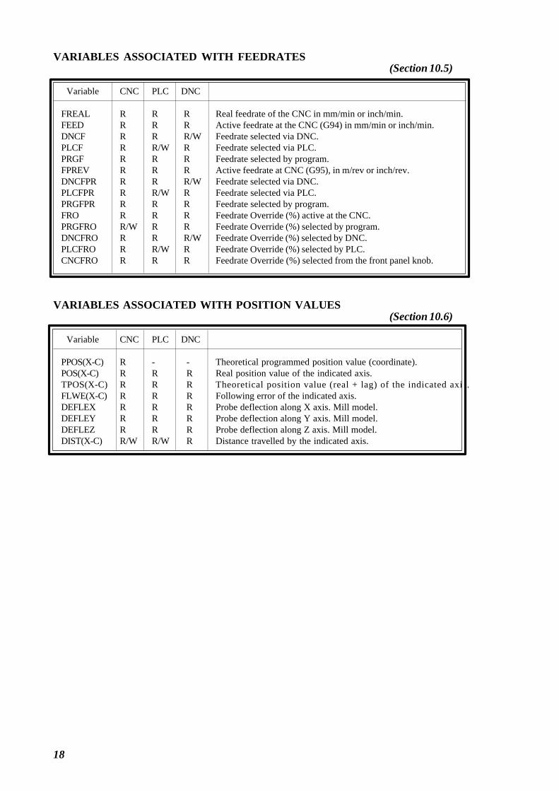
18
VARIABLES ASSOCIATED WITH FEEDRATES
Variable CNC PLC DNC
FREAL R R R Real feedrate of the CNC in mm/min or inch/min.FEED R R R Active feedrate at the CNC (G94) in mm/min or inch/min.DNCF R R R/W Feedrate selected via DNC.PLCF R R/W R Feedrate selected via PLC.PRGF R R R Feedrate selected by program.FPREV R R R Active feedrate at CNC (G95), in m/rev or inch/rev.DNCFPR R R R/W Feedrate selected via DNC.PLCFPR R R/W R Feedrate selected via PLC.PRGFPR R R R Feedrate selected by program.FRO R R R Feedrate Override (%) active at the CNC.PRGFRO R/W R R Feedrate Override (%) selected by program.DNCFRO R R R/W Feedrate Override (%) selected by DNC.PLCFRO R R/W R Feedrate Override (%) selected by PLC.CNCFRO R R R Feedrate Override (%) selected from the front panel knob.
VARIABLES ASSOCIATED WITH POSITION VALUES
Variable CNC PLC DNC
PPOS(X-C) R - - Theoretical programmed position value (coordinate).POS(X-C) R R R Real position value of the indicated axis.TPOS(X-C) R R R Theoretical position value (real + lag) of the indicated axis.FLWE(X-C) R R R Following error of the indicated axis.DEFLEX R R R Probe deflection along X axis. Mill model.DEFLEY R R R Probe deflection along Y axis. Mill model.DEFLEZ R R R Probe deflection along Z axis. Mill model.DIST(X-C) R/W R/W R Distance travelled by the indicated axis.
(Section 10.5)
(Section 10.6)

19
VARIABLES ASSOCIATED WITH THE MAIN SPINDLE
Variable CNC PLC DNC
SREAL R R R Real spindle speed in r.p.m.SPEED R R R Active spindle speed at the CNC.DNCS R R R/W Spindle speed selected via DNC.PLCS R R/W R Spindle speed selected via PLC.PRGS R R R Spindle speed selected by program.CSS R R R Constant surface feed active at the CNC in meters/min or
feet/min. Lathe model.DNCCSS R R R/W Constant surface feed selected via DNC. Lathe model.PLCCSS R R/W R Constant surface feed selected via PLC. lathe model.PRGCSS R R R Constant surface feed selected by program.SSO R R R Spindle Speed Override (%) active at the CNC.PRGSSO R/W R R Spindle Speed Override (%) selected by program.DNCSSO R R R/W Spindle Speed Override (%) selected via DNC.PLCSSO R R/W R Spindle Speed Override (%) selected via PLC.CNCSSO R R R Spindle Speed Override (%) selected from front panel.SLIMIT R R R Spindle speed limit, in rpm, active at the CNC.DNCSL R R R/W Spindle speed limit selected via DNC.PLCSL R R/W R Spindle speed limit selected via PLC.PRGSL R R R Spindle speed limit selected by program.POSS R R R Real Spindle position. Between ±999999999 ten-thousandths ºRPOSS R R R Real Spindle position. Between 0 and 360º (in ten-thousandths º )TPOSS R R R Theoretical Spindle position (real + lag)
Between ±999999999 ten-thousandths of a degree.RTPOSS R R R Theoretical Spindle position (real + lag).
Between 0 and 360º (in ten-thousandths of a degree.FLWES R R R spindle following error in Closed Loop (M19) in degrees.
VARIABLES ASSOCIATED WITH THE SECOND SPINDLE
Variable CNC PLC DNC
SSREAL R R R Real spindle speed in r.p.m.SSPEED R R R Active spindle speed at the CNC.SDNCS R R R/W Spindle speed selected via DNC.SPLCS R R/W R Spindle speed selected via PLC.SPRGS R R R Spindle speed selected by program.SCSS R R R Constant surface feed active at the CNC in meters/min or
feet/min. Lathe model.SDNCCS R R R/W Constant surface feed selected via DNC. Lathe model.SPLCCS R R/W R Constant surface feed selected via PLC. lathe model.SPRGCS R R R Constant surface feed selected by program.SSSO R R R Spindle Speed Override (%) active at the CNC.SPRGSO R/W R R Spindle Speed Override (%) selected by program.SDNCSO R R R/W Spindle Speed Override (%) selected via DNC.SPLCSO R R/W R Spindle Speed Override (%) selected via PLC.SCNCSO R R R Spindle Speed Override (%) selected from front panel.SSLIMI R R R Spindle speed limit, in rpm, active at the CNC.SDNCSL R R R/W Spindle speed limit selected via DNC.SPLCSL R R/W R Spindle speed limit selected via PLC.SPRGSL R R R Spindle speed limit selected by program.SPOSS R R R Real Spindle position. Between ±999999999 ten-thousandths ºSRPOSS R R R Real Spindle position. Between 0 and 360º (in ten-thousandths º )STPOSS R R R Theoretical Spindle position (real + lag)
Between ±999999999 ten-thousandths of a degree.SRTPOS R R R Theoretical Spindle position (real + lag).
Between 0 and 360º (in ten-thousandths of a degree.SFLWES R R R spindle following error in Closed Loop (M19) in degrees.
(Section 10.7)
(Section 10.8)

20
VARIABLES ASSOCIATED WITH THE PLC
Variable CNC PLC DNC
PLCMSG R - R Number of the active PLC message with the highest priority.PLCIn R/W - - 32 PLC inputs starting from (n).PLCOn R/W - - 32 PLC outputs starting from (n).PLCMn R/W - - 32 PLC marks starting from (n).PLCRn R/W - - Indicated (n) Register.PLCTn R/W - - Indicated (n) Timer’s count.PLCCn R/W - - Indicated (n) Counter’s count.
VARIABLES ASSOCIATED WITH GLOBAL AND LOCAL ARITHMETICPARAMETERS
Variable CNC PLC DNC
GUP n - R/W - Global parameter (n) (100-P299).LUP (a,b) - R/W - Local parameter (b) and its nesting level (a). (P0-P25).CALLP R - - Indicates which local parameters have been defined by means
of a PCALL or MCALL instruction (calling a subroutine).
OTHER VARIABLES
Variable CNC PLC DNC
OPMODE R R R Operate mode.PRGN R R R Number of the program in execution.BLKN R R R Label number of the last executed block.GSn R - - Status of the indicated G function (n).GGSA - R R Status of functions G00 thru G24.GGSB - R R Status of functions G25 thru G49.GGSC - R R Status of functions G50 thru G74.GGSD - R R Status of functions G75 thru G99.MSn R - - Status of the indicated M function (n)GMS - - R Status of M functions: M (0..6, 8, 9, 19, 30, 41..44)PLANE R R R Axes which form the active main plane.LONGAX R R R Axis affected by the tool length compensation (G15). Mill
model.MIRROR R R R Active mirror images.SCALE R R R Active general Scaling factor.SCALE(X-C) R R R Scaling Factor applied only to the indicated axis.ORGROT R R R Rotation angle (G73) of the coordinate system in degrees.
Mill model.ROTPF R - - Abscissa of rotation center. Mill model.ROTPS R - - Ordinate of rotation center. Mill model.PRBST R R R Returns probe status.CLOCK R R R System clock in seconds.TIME R R R/W Time in Hours, minutes and seconds.DATE R R R/W Date in Year-Month-Day formatTIMER R/W R/W R/W Clock activated by PLC, in seconds.CYTIME R R R Time to execute a part in hundredths of a second.PARTC R/W R/W R/W Part counter of the CNC.FIRST R R R Flag to indicate first time of program execution.KEY R/W* R/W R/W keystroke code.KEYSRC R/W R/W R/W Keystroke source, 0=keyboard, 1=PLC, 2=DNCANAIn R R R Voltage (in volts) of the indicated analog input (n).ANAOn W W W Voltage (in volts) to apply to the indicated output (n).CNCERR - R R Active CNC error number.PLCERR - - R Active PLC error number.DNCERR - R - Number of the error generated during DNC communications.
Atention: The "KEY" variable can be "written" at the CNC only via the user channel.
Programming Manual
(Section 10.9)
(Section 10.10)

21
APPENDIX E
LOGIC CNC INPUTS AND OUTPUTS
GENERAL LOGIC INPUTS
/EMERGEN M5000 Stops axis feed and spindle rotation, displaying the correspond-ing error on screen.
/STOP M5001 Stops execution of the part program, maintaining spindle rota-tion.
/FEEDHOL M5002 Stops axis feed momentarily, maintaining spindle rotation.
/XFERINH M5003 Prevents the following block from being executed, but finishesthe block which is being executed.
CYSTART M5007 Starts program execution.
SBLOCK M5008 The CNC changes to the Single Block execution mode.
MANRAPID M5009 Selects rapid travel for all the movements which are executedin Manual Mode.
OVRCAN M5010 Selects feedrate OVERRIDE at 100%.
LATCHM M5011 The axes will move from the moment the corresponding JOGkey is pressed until the STOP key is pressed.
RESETIN M5015 Initial machining conditions selected by machine parameter.
AUXEND M5016 Indicates that the execution of the M, S and T functions hascompleted.
TIMERON M5017 Enables the timer: TIMER.
TREJECT M5018 Rejection of tool in use.
PANELOFF M5019 Deactivation of keyboard.
POINT M5020 Takes a new digitized point.
PLCABORT M5022 Possibility to abort the PLC channel
PLCREADY M5023 PLC without errors.
INT1 M5024INT2 M5025 Executes the interruption subroutine whose number is assignedINT3 M5026 to general machine parameter P35, P36, P37, P38 respectively.INT4 M5027
BLKSKIP1 M5028 The “/ and /1” block skip condition is met.
BLKSKIP2 M5029 The “/2” block skip condition is met
BLKSKIP3 M5030 The “/3” block skip condition is met.
M01STOP M5031 Stops execution of the part program when the auxiliary M01function is executed.
(Section.9.1)

22
LOGIC AXES INPUTS
LIMIT+1 M5100LIMIT-1 M5101LIMIT+2 M5150LIMIT-2 M5151LIMIT+3 M5200LIMIT-3 M5201 Indicates that the axis has overrun the travel limit.LIMIT+4 M5250 The CNC stops axis feed and spindle rotation, andLIMIT-4 M5251 displays the corresponding error on screen.LIMIT+5 M5300LIMIT-5 M5301LIMIT+6 M5350LIMIT-6 M5351
DECEL1 M5102DECEL2 M5152DECEL3 M5202 Machine reference search switch is pressed.DECEL4 M5252DECEL5 M5302DECEL6 M5352
INHIBIT1 M5103INHIBIT2 M5153INHIBIT3 M5203 Momentarily prevents any axis movement.INHIBIT4 M5253INHIBIT5 M5303INHIBIT6 M5353
MIRROR1 M5104MIRROR2 M5154MIRROR3 M5204 Applies mirror image to the movements of theMIRROR4 M5254 corresponding axis.MIRROR5 M5304MIRROR6 M5354
DRO1 M5106DRO2 M5156 DRO axisDRO3 M5206 This signal must be set high andDRO4 M5256 SERVOON must be set low.DRO5 M5306DRO6 M5356
SERVO1ON M5107SERVO2ON M5157 Servo signal, must be set high in order to close theSERVO3ON M5207 positioning loop.SERVO4ON M5257SERVO5ON M5307SERVO6ON M5357
AXIS+1 M5108AXIS-1 M5109AXIS+2 M5158AXIS-2 M5159AXIS+3 M5208 Moves the axis (in the JOG Mode), in the indicatedAXIS-3 M5209 direction, positive (+) or negative (-). Similar to JOGAXIS+4 M5258 keys.AXIS-4 M5259AXIS+5 M5308AXIS-5 M5309AXIS+6 M5358AXIS-6 M5359
SYNCHRO1 M5112SYNCHRO2 M5162SYNCHRO3 M5212 Couples the axis electronically to the one defined by theSYNCHRO4 M5262 axis machine parameter “SYNCHRO”.SYNCHRO5 M5312SYNCHRO6 M5362
LIM1OFF M5115LIM2OFF M5165LIM3OFF M5215 It ignores the software limits of the corresponding axisLIM4OFF M5265LIM5OFF M5315LIM6OFF M5365
(Section.9.2)

23
(Section 9.3)
(Section 9.3)
(Section 9.4)
LOGIC MAIN SPINDLE INPUTS
LIMIT+S M5450 Indicates that the spindle has overrun the travel limit. TheLIMIT-S M5451 CNC stops axis feed and spindle rotation, and displays the corre-
sponding error on screen.
DECELS M5452 Machine reference search switch pressed.
SPDLEINH M5453 Sends out zero analog output for spindle.
SPDLEREV M5454 Reverses spindle rotation direction.
SERVOSON M5457 Servo signal must be at high logic level to be able to move thespindle in Closed Loop (M19).
GEAR1 M5458 Indicates which spindle speed range is selected.GEAR2 M5459GEAR3 M5460GEAR4 M5461
PLCM19 M5464 Indicates positioning and fast synchronized speed in M19M19FEED R505
PLCCNTL M5465 The spindle is controlled directly by the PLC.
SANALOG R504 Indicates spindle analog output. Only for the spindle controlled bythe PLC.
LOGIC SECOND SPINDLE INPUTS
LIMIT+S2 M5475 Indicates that the spindle has overrun the travel limit. TheLIMIT-S2 M5476 CNC stops axis feed and spindle rotation, and displays the corre-
sponding error on screen.
DECELS M5477 Machine reference search switch pressed.
SPDLEINH M5478 Sends out zero analog output for spindle.
SPDLEREV M5479 Reverses spindle rotation direction.
SERVOSON M5482 Servo signal must be at high logic level to be able to move thespindle in Closed Loop (M19).
GEAR1 M5483 Indicates which spindle speed range is selected.GEAR2 M5484GEAR3 M5485GEAR4 M5486
PLCM19 M5489 Indicates positioning and fast synchronized speed in M19M19FEED R507
PLCCNTL M5490 The spindle is controlled directly by the PLC.
SANALOG R506 Indicates spindle analog output. Only for the spindle controlled bythe PLC.
LOGIC KEY INHIBITION INPUTS
KEYDIS1 R500KEYDIS2 R501KEYDIS3 R502 Inhibit the operation of the panel keys.KEYDIS4 R503

24
GENERAL LOGIC OUTPUTS
CNCREADY M5500 CNC without errors.
START M5501 Indicates that the START key on the Front Panel has beenpressed.
FHOUT M5502 Indicates that program execution has been stopped.
RESETOUT M5503 Indicates that the CNC is set at initial conditions.
LOPEN M5506 Indicates that the positioning loop for the axes is open.
/ALARM M5507 An alarm or emergency condition was detected.
MANUAL M5508 The Manual Operation (JOG) Mode has been selected.
AUTOMAT M5509 The Automatic Operation Mode has been selected.
MDI M5510 The MDI mode has been selected.
SBOUT M5511 The Single Block Execution Mode has been selected.
INCYCLE M5515 The part program is being executed.
RAPID M5516 A rapid traverse is being executed (G00).
TAPPING M5517 A tapping cycle is being executed (G84). Mill model.
THREAD M5518 A threading block is being executed (G33).
PROBE M5519 A probing movement is being executed (G75/G76).
ZERO M5520 A machine reference search is being executed (G74).
RIGID M5521 A rigid tapping block in execution. Mill model.
CSS M5523 The G96 function is selected.
SELECT0 M5524SELECT1 M5525 Indicates in code the position selected on Front PanelSELECT2 M5526 switch.SELECT3 M5527SELECT4 M5528
MSTROBE M5532 Indicates that the auxiliary M functions which areindicated in registers R550 to R556 must be executed.
SSTROBE M5533 Indicates that the auxiliary S function of register R557must be executed.
TSTROBE M5534 Indicates that the auxiliary T function of register R558must be executed.
T2STROBE M5535 Indicates that the auxiliary T function of register R559must be executed.
S2MAIN M5536 Indicates which spindle is controlled by the CNC.
(Section 9.5)

25
ADVINPOS M5537 For punch presses. Indicates that the punching may begin.
INTEREND M5538 Indicates that interpolation has concluded.
INPOS M5539 Axes are in position.
DM00 M5547 The execution of the program has stopped after executingthe auxiliary M00 function.
DM01 M5546 The execution of the program has stopped after executingthe auxiliary M01 function.
DM02 M5545 The execution of the program has stopped after executingthe auxiliary M02 function.
DM03 M5544 The spindle is turning clockwise (M03).
DM04 M5543 The spindle is turning counter-clockwise (M04).
DM05 M5542 The spindle is stopped (M05).
DM06 M5541 The auxiliary M06 function has been executed.
DM08 M5540 The coolant output has been activated (M08).
DM09 M5555 The coolant output has been deactivated (M09).
DM19 M5554 A block with spindle stop has been executed (M19).
DM30 M5553 The program concluded after executing the auxiliary M30function.
DM41 M5552 The first spindle speed range has been selected (M41).
DM42 M5551 The second spindle speed range has been selected (M42).
DM43 M5550 The third spindle speed range has been selected (M43).
DM44 M5549 The fourth spindle speed range has been selected (M44).
DM45 M5548 Auxiliary spindle or live tool activated (M45).

26
AXES LOGIC OUTPUTS
ENABLE1 M5600ENABLE2 M5650ENABLE3 M5700 Allow movement of axis.ENABLE4 M5750ENABLE5 M5800
ENABLE6 M5850
DIR1 M5601DIR2 M5651DIR3 M5701 Indicate axis movement direction.DIR4 M5751DIR5 M5801DIR6 M5851
ANT1 M5606ANT2 M5656 If the programmed movement is smaller than the valueANT3 M5706 of axis parameter "MINMOVE (P54)", the ANT* outputANT4 M5756 goes high.ANT5 M5806ANT6 M5856
REFPOIN1 M5602REFPOIN2 M5652REFPOIN3 M5702 Machine reference search has already been done.REFPOIN4 M5752REFPOIN5 M5802REFPOIN6 M5852
INPOS1 M5607INPOS2 M5657INPOS3 M5707 The corresponding axis is in position.INPOS4 M5757INPOS5 M5807INPOS6 M5857
(Section 9.6)

27
LOGIC MAIN SPINDLE OUTPUTS
ENABLES M5950 Allows movement of spindle.
DIRS M5951 Indicates in which direction the spindle is moving.
REFPOINS M5952 The spindle reference point search has already been done.
CAXIS M5955 The C axis is active
REVOK M5956 The real revolutions of the spindle correspond to pro-grammed ones.
INPOSS M5957 The spindle is in position.
LOGIC SECOND SPINDLE OUTPUTS
ENABLES2 M5975 Allows movement of spindle.
DIRS2 M5976 Indicates in which direction the spindle is moving.
REFPOIS2 M5977 The spindle reference point search has already been done.
CAXIS2 M5980 The C axis is active
REVOK2 M5981 The real revolutions of the spindle correspond to pro-grammed ones.
INPOSS2 M5982 The spindle is in position.
LOGIC AUXILIARY M, S, T FUNCTION OUTPUTS
MBCD1 R550MBCD2 R551MBCD3 R552 Indicate the auxiliary M functions whichMBCD4 R553 must be executed.MBCD5 R554MBCD6 R555MBCD7 R556
SBCD R557 Indicates spindle speed in BCD (2 or 8 digits).
TBCD R558 Indicates the magazine position of the tool to be placedin the spindle.
T2BCD R559 Indicates the magazine position (pocket) for the tool whichwas in the spindle.
LOGIC OUTPUTS OF KEY STATUS
KEYBD1 R560KEYBD2 R561 Indicate whether a key of the operator panel is pressed.KEYBD3 R562
(Section 9.7)
(Section 9.7)
(Section 8.1)
(Section 9.8)

28
APPENDIX F
CONVERSION TABLE FOR S OUTPUT IN 2-DIGIT BCD CODE
Programmed S “SBCD” Programmed S “SBCD”
0 S00 180-199 S651 S20 200-223 S662 S26 224-249 S673 S29 250-279 S684 S32 280-314 S695 S34 315-354 S706 S35 355-399 S717 S36 400-449 S728 S38 450-499 S739 S39 500-559 S74
10-11 S40 560-629 S7512 S41 630-709 S7613 S42 710-799 S7714-15 S43 800-899 S7816-17 S44 900-999 S7918-19 S45 1000-1119 S8020-22 S46 1120-1249 S8123-24 S47 1250-1399 S8225-27 S48 1400-1599 S8328-31 S49 1600-1799 S84
32-35 S50 1800-1999 S8536-39 S51 2000-2239 S8640-44 S52 2240-2499 S8745-49 S53 2500-2799 S8850-55 S54 2800-3149 S8956-62 S55 3150-3549 S9063-70 S56 3550-3999 S9171-79 S57 4000-4499 S9280-89 S58 4500-4999 S9390-99 S59 5000-5599 S94
100-111 S60 5600-6299 S95112-124 S61 6300-7099 S96125-139 S62 7100-7999 S97140-159 S63 8000-8999 S98160-179 S64 9000-9999 S99

29
Key Hexadecimal Decimal
A $61 097A+SHIFT $41 065A+CAPS $41 065A+SHIFT+CAPS $61 097
B $62 098B+SHIFT $42 066B+CAPS $42 066B+SHIFT+CAPS $62 098
C $63 099C+SHIFT $43 067C+CAPS $43 067C+SHIFT+CAPS $63 099
D $64 100D+SHIFT $44 068D+CAPS $44 068D+SHIFT+CAPS $64 100
E $65 101E+SHIFT $45 069E+CAPS $45 069E+SHIFT+CAPS $65 101
F $66 102F+SHIFT $46 070F+CAPS $46 070F+SHIFT+CAPS $66 102
G $67 103G+SHIFT $47 071G+CAPS $47 071G+SHIFT+CAPS $67 103
Key Hexadecimal Decimal
H $68 104H+SHIFT $48 072H+CAPS $48 072H+SHIFT+CAPS $68 104
I $69 105I+SHIFT $49 073I+CAPS $49 073I+SHIFT+CAPS $69 105
J $6A 106J+SHIFT $4A 074J+CAPS $4A 074J+SHIFT+CAPS $6A 106
K $6B 107K+SHIFT $4B 075K+CAPS $4B 075K+SHIFT+CAPS $6B 107
L $6C 108L+SHIFT $4C 076L+CAPS $4C 076L+SHIFT+CAPS $6C 108
M $6D 109M+SHIFT $4D 077M+CAPS $4D 077M+SHIFT+CAPS $6D 109
N $6E 110N+SHIFT $4E 078N+CAPS $4E 078N+SHIFT+CAPS $6E 110
APPENDIX G
KEY CODES
Each key can generate up to four different codes when pressed, depending on the status of the SHIFTand CAPS functions.
Therefore, when key A is pressed the following codes are obtained:
Hexad. Decimal$61 097 If, when key A is pressed, no function is selected.$41 065 If, when key A is pressed, the SHIFT function is selected.$41 065 If, when key A is pressed, the CAPS function is selected.$61 097 If, when key A is pressed, both functions are selected.

30
Key Hexadecimal Decimal
U $75 117U+SHIFT $55 085U+CAPS $55 085U+SHIFT+CAPS $75 117
V $76 118V+SHIFT $56 086V+CAPS $56 086V+SHIFT+CAPS $76 118
W $77 119W+SHIFT $57 087W+CAPS $57 087W+SHIFT+CAPS $77 119
X $78 120X+SHIFT $58 088X+CAPS $58 088X+SHIFT+CAPS $78 120
Y $79 121Y+SHIFT $59 089Y+CAPS $59 089Y+SHIFT+CAPS $79 121
Z $7A 122Z+SHIFT $5A 090Z+CAPS $5A 090Z+SHIFT+CAPS $7A 122
SP $20 032SP+SHIFT $20 032SP+CAPS $20 032SP+SHIFT+CAPS $20 032
Key Hexadecimal Decimal
Ñ $A5 164Ñ+SHIFT $A4 165Ñ+CAPS $A4 165Ñ+SHIFT+CAPS $A5 164
O $6F 111O+SHIFT $4F 079O+CAPS $4F 079O+SHIFT+CAPS $6F 111
P $70 112P+SHIFT $50 080P+CAPS $50 080P+SHIFT+CAPS $70 112
Q $71 113Q+SHIFT $51 081Q+CAPS $51 081Q+SHIFT+CAPS $71 113
R $72 114R+SHIFT $52 082R+CAPS $52 082R+SHIFT+CAPS $72 114
S $73 115S+SHIFT $53 083S+CAPS $53 083S+SHIFT+CAPS $73 115
T $74 116T+SHIFT $54 084T+CAPS $54 084T+SHIFT+CAPS $74 116

31
Key Hexadecimal Decimal
; 0 $30 048 +SHIFT $3B 059 +CAPS $30 048 +SHIFT+CAPS $3B 059
! 1 $31 049 +SHIFT $21 033 +CAPS $31 049 +SHIFT+CAPS $21 033
“ 2 $32 050 +SHIFT $22 034 +CAPS $32 050 +SHIFT+CAPS $22 034
, 3 $33 051 +SHIFT $27 039 +CAPS $33 051 +SHIFT+CAPS $27 039
[ 4 $34 052 +SHIFT $5B 091 +CAPS $34 052 +SHIFT+CAPS $5B 091
] 5 $35 053 +SHIFT $5D 093 +CAPS $35 053 +SHIFT+CAPS $5D 093
& 6 $36 054 +SHIFT $26 038 +CAPS $36 054 +SHIFT+CAPS $26 038
( 7 $37 055 +SHIFT $28 040 +CAPS $37 055 +SHIFT+CAPS $28 040
Key Hexadecimal Decimal
) 8 $38 056 +SHIFT $29 041 +CAPS $38 056 +SHIFT+CAPS $29 041
$ 9 $39 057 +SHIFT $24 036 +CAPS $39 057 +SHIFT+CAPS $24 036
: . $2E 046 +SHIFT $3A 058 +CAPS $2E 046 +SHIFT+CAPS $3A 058
> + $2B 043 +SHIFT $3E 062 +CAPS $2B 043 +SHIFT+CAPS $3E 062
< - $2D 045 +SHIFT $3C 060 +CAPS $2D 045 +SHIFT+CAPS $3C 060
? * $2A 042 +SHIFT $3F 063 +CAPS $2A 042 +SHIFT+CAPS $3F 063
% / $2F 047 +SHIFT $25 037 +CAPS $2F 047 +SHIFT+CAPS $25 037
# = $3D 061 +SHIFT $23 035 +CAPS $3D 061 +SHIFT+CAPS $23 035

32
Key Hexadecimal Decimal
ENTER $0D 013 +SHIFT $0D 013 +CAPS $0D 013 +SHIFT+CAPS $0D 013
HELP $FFF2 65522 +SHIFT $FFF2 65522 +CAPS $FFF2 65522 +SHIFT+CAPS $FFF2 65522
RESET $FFF3 65523 +SHIFT +CAPS $FFF3 65523 +SHIFT+CAPS
ESC $1B 027ESC+SHIFT $1B 027ESC+CAPS $1B 027ESC+SHIFT+CAPS $1B 027
MAIN MENU $FFF4 65524 +SHIFT $FFF4 65524 +CAPS $FFF4 65524 +SHIFT+CAPS $FFF4 65524
CL $FFAD 65453CL+SHIFTCL+CAPS $FFAD 65453CL+SHIFT+CAPS
INS $FFAE 65454INS+SHIFT $FFAE 65454INS+CAPS $FFAE 65454INS+SHIFT+CAPS $FFAE 65454
Key Hexadecimal Decimal
Previous Page $FFA5 65445 +SHIFT $FFA5 65445 +CAPS $FFA5 65445 +SHIFT+CAPS $FFA5 65445
Next Page $FFAF 65455 +SHIFT +CAPS $FFA5 65455 +SHIFT+CAPS
Up arrow $FFB0 65456 +SHIFT $FFB1 65457 +CAPS $FFB0 65456 +SHIFT+CAPS $FFB1 65457
Down arrow $FFB2 65458 +SHIFT $FFB3 65459 +CAPS $FFB2 65458 +SHIFT+CAPS $FFB3 65459
Left arrow $FFB4 65460 +SHIFT $FFB5 65461 +CAPS $FFB4 65460 +SHIFT+CAPS $FFB5 65461
Right arrow $FFB6 65462 +SHIFT $FFB7 65463 +CAPS $FFB6 65462 +SHIFT+CAPS $FFB7 65463

33
Key Hexadecimal Decimal
F1 $FC00 64512F1+SHIFT $FC00 64512F1+CAPS $FC00 64512F1+SHIFT+CAPS $FC00 64512
F2 $FC01 64513F2+SHIFT $FC01 64513F2+CAPS $FC01 64513F2+SHIFT+CAPS $FC01 64513
F3 $FC02 64514F3+SHIFT $FC02 64514F3+CAPS $FC02 64514F3+SHIFT+CAPS $FC02 64514
F4 $FC03 64515F4+SHIFT $FC03 64515F4+CAPS $FC03 64515F4+SHIFT+CAPS $FC03 64515
F5 $FC04 64516F5+SHIFT $FC04 64516F5+CAPS $FC04 64516F5+SHIFT+CAPS $FC04 64516
F6 $FC05 64517F6+SHIFT $FC05 64517F6+CAPS $FC05 64517F6+SHIFT+CAPS $FC05 64517
F7 $FC06 64518F7+SHIFT $FC06 64518F7+CAPS $FC06 64518F7+SHIFT+CAPS $FC06 64518
Key Hexadecimal Decimal
Cycle Start $FFF1 65521 +SHIFT $FFF1 65521 +CAPS $FFF1 65521 +SHIFT+CAPS $FFF1 65521
Cycle Stop $FFF0 65520 +SHIFT $FFF0 65520 +CAPS $FFF0 65520 +SHIFT+CAPS $FFF0 65520

34
MACHINEPARAMETER VALUE
MACHINEPARAMETER VALUE
APPENDIX H
MACHINE PARAMETER SETTING
GENERAL PARAMETERS
MACHINEPARAMETER VALUE
P 0 P 24 P 48
P 1 P 25 P 49
P 2 P 26 P 50
P 3 P 27 P 51
P 4 P 28 P 52
P 5 P 29 P 53
P 6 P 30 P 54
P 7 P 31 P 55
P 8 P 32 P 56
P 9 P 33 P 57
P 10 P 34 P 58
P 11 P 35 P 59
P 12 P 36 P 60
P 13 P 37 P 61
P 14 P 38 P 62
P 15 P 39 P 63
P 16 P 40 P 64
P 17 P 41 P 65
P 18 P 42 P 66
P 19 P 43 P 67
P 20 P 44 P 68
P 21 P 45 P 69
P 22 P 46 P 70
P 23 P 47 P 71

35
AXIS PARAMETERS
MACHINE PARAMETER VALUE
P 0 P 24 P 48
P 1 P 25 P 49
P 2 P 26 P 50
P 3 P 27 P 51
P 4 P 28 P 52
P 5 P 29 P 53
P 6 P 30 P 54
P 7 P 31 P 55
P 8 P 32 P 56
P 9 P 33 P 57
P 10 P 34 P 58
P 11 P 35 P 59
P 12 P 36 P 60
P 13 P 37 P 61
P 14 P 38 P 62
P 15 P 39 P 63
P 16 P 40 P 64
P 17 P 41 P 65
P 18 P 42 P 66
P 19 P 43 P 67
P 20 P 44 P 68
P 21 P 45 P 69
P 22 P 46 P 70
P 23 P 47 P 71
MACHINEPARAMETER VALUE
MACHINEPARAMETER VALUE

36
AXIS PARAMETERS
MACHINEPARAMETER VALUE
P 0 P 24 P 48
P 1 P 25 P 49
P 2 P 26 P 50
P 3 P 27 P 51
P 4 P 28 P 52
P 5 P 29 P 53
P 6 P 30 P 54
P 7 P 31 P 55
P 8 P 32 P 56
P 9 P 33 P 57
P 10 P 34 P 58
P 11 P 35 P 59
P 12 P 36 P 60
P 13 P 37 P 61
P 14 P 38 P 62
P 15 P 39 P 63
P 16 P 40 P 64
P 17 P 41 P 65
P 18 P 42 P 66
P 19 P 43 P 67
P 20 P 44 P 68
P 21 P 45 P 69
P 22 P 46 P 70
P 23 P 47 P 71
MACHINEPARAMETER VALUE
MACHINEPARAMETER VALUE

37
MACHINEPARAMETER VALUE
P 0 P 24 P 48
P 1 P 25 P 49
P 2 P 26 P 50
P 3 P 27 P 51
P 4 P 28 P 52
P 5 P 29 P 53
P 6 P 30 P 54
P 7 P 31 P 55
P 8 P 32 P 56
P 9 P 33 P 57
P 10 P 34 P 58
P 11 P 35 P 59
P 12 P 36 P 60
P 13 P 37 P 61
P 14 P 38 P 62
P 15 P 39 P 63
P 16 P 40 P 64
P 17 P 41 P 65
P 18 P 42 P 66
P 19 P 43 P 67
P 20 P 44 P 68
P 21 P 45 P 69
P 22 P 46 P 70
P 23 P 47 P 71
MACHINEPARAMETER VALUE
MACHINEPARAMETER VALUE
AXISPARAMETERS

38
MACHINEPARAMETER VALUE
P 0 P 24 P 48
P 1 P 25 P 49
P 2 P 26 P 50
P 3 P 27 P 51
P 4 P 28 P 52
P 5 P 29 P 53
P 6 P 30 P 54
P 7 P 31 P 55
P 8 P 32 P 56
P 9 P 33 P 57
P 10 P 34 P 58
P 11 P 35 P 59
P 12 P 36 P 60
P 13 P 37 P 61
P 14 P 38 P 62
P 15 P 39 P 63
P 16 P 40 P 64
P 17 P 41 P 65
P 18 P 42 P 66
P 19 P 43 P 67
P 20 P 44 P 68
P 21 P 45 P 69
P 22 P 46 P 70
P 23 P 47 P 71
AXISPARAMETERS
MACHINEPARAMETER VALUE
MACHINEPARAMETER VALUE

39
MACHINEPARAMETER VALUE
P 0 P 24 P 48
P 1 P 25 P 49
P 2 P 26 P 50
P 3 P 27 P 51
P 4 P 28 P 52
P 5 P 29 P 53
P 6 P 30 P 54
P 7 P 31 P 55
P 8 P 32 P 56
P 9 P 33 P 57
P 10 P 34 P 58
P 11 P 35 P 59
P 12 P 36 P 60
P 13 P 37 P 61
P 14 P 38 P 62
P 15 P 39 P 63
P 16 P 40 P 64
P 17 P 41 P 65
P 18 P 42 P 66
P 19 P 43 P 67
P 20 P 44 P 68
P 21 P 45 P 69
P 22 P 46 P 70
P 23 P 47 P 71
MACHINEPARAMETER VALUE
MACHINEPARAMETER VALUE
AXISPARAMETERS

40
SPINDLE PARAMETERS
MACHINEPARAMETER VALUE
P 0 P 24 P 48
P 1 P 25 P 49
P 2 P 26 P 50
P 3 P 27 P 51
P 4 P 28 P 52
P 5 P 29 P 53
P 6 P 30 P 54
P 7 P 31 P 55
P 8 P 32 P 56
P 9 P 33 P 57
P 10 P 34 P 58
P 11 P 35 P 59
P 12 P 36 P 60
P 13 P 37 P 61
P 14 P 38 P 62
P 15 P 39 P 63
P 16 P 40 P 64
P 17 P 41 P 65
P 18 P 42 P 66
P 19 P 43 P 67
P 20 P 44 P 68
P 21 P 45 P 69
P 22 P 46 P 70
P 23 P 47 P 71
MACHINEPARAMETER VALUE
MACHINEPARAMETER VALUE

41
RS-232C MACHINE PARAMETERS
MACHINEPARAMETER VALUE
P 0 P 24 P 48
P 1 P 25 P 49
P 2 P 26 P 50
P 3 P 27 P 51
P 4 P 28 P 52
P 5 P 29 P 53
P 6 P 30 P 54
P 7 P 31 P 55
P 8 P 32 P 56
P 9 P 33 P 57
P 10 P 34 P 58
P 11 P 35 P 59
P 12 P 36 P 60
P 13 P 37 P 61
P 14 P 38 P 62
P 15 P 39 P 63
P 16 P 40 P 64
P 17 P 41 P 65
P 18 P 42 P 66
P 19 P 43 P 67
P 20 P 44 P 68
P 21 P 45 P 69
P 22 P 46 P 70
P 23 P 47 P 71
MACHINEPARAMETER VALUE
MACHINEPARAMETER VALUE

42
RS-422 MACHINE PARAMETERS
MACHINEPARAMETER VALUE
P 0 P 24 P 48
P 1 P 25 P 49
P 2 P 26 P 50
P 3 P 27 P 51
P 4 P 28 P 52
P 5 P 29 P 53
P 6 P 30 P 54
P 7 P 31 P 55
P 8 P 32 P 56
P 9 P 33 P 57
P 10 P 34 P 58
P 11 P 35 P 59
P 12 P 36 P 60
P 13 P 37 P 61
P 14 P 38 P 62
P 15 P 39 P 63
P 16 P 40 P 64
P 17 P 41 P 65
P 18 P 42 P 66
P 19 P 43 P 67
P 20 P 44 P 68
P 21 P 45 P 69
P 22 P 46 P 70
P 23 P 47 P 71
MACHINEPARAMETER VALUE
MACHINEPARAMETER VALUE

43
PLC MACHINE PARAMETERS
MACHINEPARAMETER VALUE
P 0 P 24 P 48
P 1 P 25 P 49
P 2 P 26 P 50
P 3 P 27 P 51
P 4 P 28 P 52
P 5 P 29 P 53
P 6 P 30 P 54
P 7 P 31 P 55
P 8 P 32 P 56
P 9 P 33 P 57
P 10 P 34 P 58
P 11 P 35 P 59
P 12 P 36 P 60
P 13 P 37 P 61
P 14 P 38 P 62
P 15 P 39 P 63
P 16 P 40 P 64
P 17 P 41 P 65
P 18 P 42 P 66
P 19 P 43 P 67
P 20 P 44 P 68
P 21 P 45 P 69
P 22 P 46 P 70
P 23 P 47 P 71
MACHINEPARAMETER VALUE
MACHINEPARAMETER VALUE

44
M FUNCTIONS
M ASSOCIATED Bits to be set FUNCTION SUBROUTINE 7 6 5 4 3 2 1 0
M S
M S
M S
M S
M S
M S
M S
M S
M S
M S
M S
M S
M S
M S
M S
M S
M S
M S
M S
M S

45
M FUNCTIONS
M ASSOCIATED Bits to be set FUNCTION SUBROUTINE 7 6 5 4 3 2 1 0
M S
M S
M S
M S
M S
M S
M S
M S
M S
M S
M S
M S
M S
M S
M S
M S
M S
M S
M S
M S

46
ERRORPOSITION POSITION ERROR
P E
P E
P E
P E
P E
P E
P E
P E
P E
P E
P E
P E
P E
P E
P E
P E
P E
P E
P E
POINT NUMBER
LEADSCREW ERROR COMPENSATION FOR AXIS
POINT NUMBER
P E
P E
P E
P E
P E
P E
P E
P E
P E
P E
P E
P E
P E
P E
P E
P E
P E
P E
P E

47
LEADSCREW ERROR COMPENSATION FOR AXIS
POINT NUMBER
P E
P E
P E
P E
P E
P E
P E
P E
P E
P E
P E
P E
P E
P E
P E
P E
P E
P E
P E
ERRORPOSITION POSITION ERROR
P E
P E
P E
P E
P E
P E
P E
P E
P E
P E
P E
P E
P E
P E
P E
P E
P E
P E
P E
POINT NUMBER

48
LEADSCREW ERROR COMPENSATION FOR AXIS
POINT NUMBER
P E
P E
P E
P E
P E
P E
P E
P E
P E
P E
P E
P E
P E
P E
P E
P E
P E
P E
P E
ERRORPOSITION POSITION ERROR
P E
P E
P E
P E
P E
P E
P E
P E
P E
P E
P E
P E
P E
P E
P E
P E
P E
P E
P E
POINT NUMBER

49
LEADSCREW ERROR COMPENSATION FOR AXIS
POINT NUMBER
P E
P E
P E
P E
P E
P E
P E
P E
P E
P E
P E
P E
P E
P E
P E
P E
P E
P E
P E
ERRORPOSITION POSITION ERROR
P E
P E
P E
P E
P E
P E
P E
P E
P E
P E
P E
P E
P E
P E
P E
P E
P E
P E
P E
POINT NUMBER

50
LEADSCREW ERROR COMPENSATION FOR AXIS
POINT NUMBER
P E
P E
P E
P E
P E
P E
P E
P E
P E
P E
P E
P E
P E
P E
P E
P E
P E
P E
P E
ERRORPOSITION POSITION ERROR
P E
P E
P E
P E
P E
P E
P E
P E
P E
P E
P E
P E
P E
P E
P E
P E
P E
P E
P E
POINT NUMBER

51
ERRORPOSITION POSITION ERROR
P E
P E
P E
P E
P E
P E
P E
P E
P E
P E
P E
P E
P E
P E
P E
P E
P E
P E
P E
POINT NUMBER
FIRST CROSS COMPENSATION TABLE
Moving axis "MOVAXIS" :Axis to compensate "COMPAXIS" :
POINT NUMBER
P E
P E
P E
P E
P E
P E
P E
P E
P E
P E
P E
P E
P E
P E
P E
P E
P E
P E
P E

52
ERRORPOSITION POSITION ERROR
P E
P E
P E
P E
P E
P E
P E
P E
P E
P E
P E
P E
P E
P E
P E
P E
P E
P E
P E
POINT NUMBER
SECOND CROSS COMPENSATION TABLE
Moving axis "MOVAXIS" :Axis to be compensated "COMAXIS2" :
POINT NUMBER
P E
P E
P E
P E
P E
P E
P E
P E
P E
P E
P E
P E
P E
P E
P E
P E
P E
P E
P E

53
ERRORPOSITION POSITION ERROR
P E
P E
P E
P E
P E
P E
P E
P E
P E
P E
P E
P E
P E
P E
P E
P E
P E
P E
P E
POINT NUMBER
THIRD CROSS COMPENSATION TABLE
Moving axis "MOVAXIS" :Axis to be compensated "COMAXIS3" :
POINT NUMBER
P E
P E
P E
P E
P E
P E
P E
P E
P E
P E
P E
P E
P E
P E
P E
P E
P E
P E
P E

54
APPENDIX I
MAINTENANCE
Cleaning:
The accumulated dirt inside the unit may act as a screen preventing the proper dissipation of the heatgenerated by the internal circuitry which could result in a harmful overheating of the CNC and,consequently, possible malfunctions.
On the other hand, accumulated dirt can sometimes act as an electrical conductor and shortcircuit theinternal circuitry, especially under high humidity conditions.
To clean the operator panel and the monitor, a smooth cloth should be used which has beendipped into de-ionized water and /or non abrasive dish-washer soap (liquid, never powder) or75º alcohol.
Do not use highly compressed air to clean the unit because it could generate electrostaticdischarges.
The plastics used on the front panel are resistant to :
1.- Grease and mineral oils2.- Bases and bleach3.- Dissolved detergents4.- Alcohol
Avoid the action of solvents such as Chlorine hydrocarbons , Benzole , Esters andEther which can damage the plastics used to make the unit’s front panel.
Preventive Inspection:
If the CNC does not turn on when actuating the start-up switch, verify that the monitor fuse as well as thatof the power supply module of the Central Unit are in good condition and that they are the right ones.
The Power Supply unit of the Central Unit has two 3.15Amp./250V fast fuses (F), one per line.

55
To check the fuses, first disconnect the power to the CNC.
Do not manipulate inside this unit.Only personnel authorized by Fagor Automation may manipulate inside this mo-dule.
Do not manipulate the connectors with the unit connected to main AC power.Before manipulating these connectors, make sure that the unit is not connectedto main AC power.
Note :Fagor Automation shall not be held responsible for any material or physicaldamage derived from the violation of these basic safety requirements.
List of materials, parts that could be replaced
Part Description Code Manufacturer Reference
Rear Panel w/ 4 modulesw/ 6 modules
8050002380500024 Fagor Automation
Power Supply Module 80500001
CPU Module w/ 128Kw/ 640K
8050007580500076 Fagor Automation
Eprom cartridge w/ 32Kw/ 128K
8050008180500082 Fagor Automation
Axes Module 80500004 Fagor Automation
Input/Output Module 80500006 Fagor Automation
Input/Output and Tracing Module 83210000 Fagor Automation
Fan Module w/ 4 modules w/6 modules
8050002580500026 Fagor Automation
9" Monitor for 8050Mfor 8050T
8339000083390001 Fagor Automation
10" Monitor for 8050Mfor 8050T
8342000183420003 Fagor Automation
14" Monitor 83420004 Fagor Automation
Operator Panel 8050M w/o Handwheelw/ Handwheel
8030001080300014 Fagor Automation
Operator Panel 8050T w/o Handwheelw/ Handwheel
8030001180300015 Fagor Automation
Set of cables5 m10 m15 m
805000188050001980500020
Fagor Automation
Mains AC Cable 3x0,75 11313000 Fagor Automation
3.15A/250V Fuse 12130015 SchurterWickmann
FST-034-1521Ref. 19115
ManualOEMUSER (M)USER (T)
837500048375000283750000
Fagor Automation