cnc serie 550 - givimisure india pvt ltd · · 2013-08-03by developing the serie 550, ......
TRANSCRIPT
cnc serie 550

By developing the Serie 550, Esa/GV’s intention was to update its range of numeric controls for press brakes, shears and plate rolls forming machines, true to its tradition of on-going research based on precise guidelines:l maintain full compatibility with the current kvara6 products familyl be more configurable and scaleable, preferring flexibility and interconnectivity of a limited number of functional modules to a variety of
models l provide a high processing capacityl sensibly reduce the size of the mechanical components of the numeric controll interface the digital drives of the Esa-dMotion Seriesl put the finishing touches to the re-vamping process begun with kvara, particularly in relation to the operator panels, by proposing elegant, easily
customized housings, ready for installation on the machines tool
Third Parts I/O
CAN Interface (6)
Third Parts Motors or Esa/Gv ED Servomotors
Operator Panel Direct Connection
Expansions (2)
Operator Panel , Keyboard &
Accessories (7)
Operator Panel Enclosures (8)
Ethernet Connection
CNC SERIE 500 Industrial PC (9)
Stand-alone remote I/O (5)
Base NC Module (1)
Axes Digital Interfaces (3)
CN / PC Interconnection (10)
Modular Remote I/O (4)
cnc Serie 550 - Modules and interconnections
cnc serie 550

1) BASE NC MODulE
The basic NC module is available in 3 versions with different CPU types and communication ports
cnc Serie 550 BASIC
cnc Serie 550 PluS cnc Serie 550 TOP
CPu / Dynamic RAM AMD ElAN 520 - 133MHz - 32MB Intel Celeron M – 600MHz – 256MB Intel Celeron M – 1.8GHz – 1GB
Silicon Disk 32 MB (built into the DIMM module) 256MB 256MB
Battery backuped RAM 1 MB (lithium backup battery)
FlASH memory 8MB
Ethernet ports No 1 + 1 (Optional) 1 + 1 (Optional)
RS 232 Serial ports - N.2 - Com2 can be configured also as RS 422/485
VGA video output No 1 1
PS2 Mouse & Keyboard Si Si Si
uSB Ports 1 ( vers.1.1) N.2 + 1 (vers. 2.0) optional (*) N.2 (1.1) + N. 1 (2.0) optional (*)
CAN interfaces 2
ESAring interface 1
Analog inputs 4
Analog outputs 1
Fast inputs 4
PC104 connector 1
Power supply/consumption 24Vdd ± 20% - 60W max
Dimensions (H x W x D) 282 x 53,5 x 156
Temp. Working range 5 ÷ 50 ° C
(*) available using the option for remoting up to 10m PS2
2) ExPANSION MODulES
These modules can be easily connected to the body of the NC. Physically, they look the same as the NC, as they are the same height, not so wide (106mm as against 156mm) and are around 20mm thick.
MODulES DESCRIPTION
4 Analog axes module - part code BRD.021.461:4 fast counting circuits (maximum frequency 2MHz) for Line Drive 0-5Vdc differential encoders. The encoders are directly powered at 5Vdc (max 200mA per channel). Cable breaking and transducer alarm status are detected and signalled.four ±10V analog outputs with 15bits + sign resolutionfour digital inputs for the zero microsfour inputs for instantly memorizing the axes targets (touch probe). The active front setting can be selected.
32 Digital Input + 32 Digital Output - part code BRD.007.461Both the inputs and the outputs are located on 4 removable terminal boards with 3.5mm pitchinputs specifications: optoinsulated; operating range 20÷28Vdc - 10ms HW filteroutputs specifications: 0.7A maximum; operating range 20÷28Vdc, thermally protected against overloads and short-circuits
2 current outputs (up to 3.4A each); power supply 24Vdc±15%, with 8 bits resolution (typically used in applications for press-brakes, for regulating the bending pressure and the hydraulic crowning table)4 optoinsulated current outputs (up to 2.8A each); power supply 24Vdc±15%, with 14bits resolution (typically used in for regulating the proportional valves of cylinders Y1 and Y2)
Note: The full scale and offset regulation of each output is completely digital
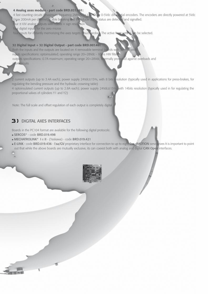
3) DIGITAl AxES INTERFACES
Boards in the PC104 format are available for the following digital protocols:l
SERCOS® - code BRD.019.498l
MECHATROlINK®
I e II - (Yaskawa) - code BRD.019.421
l
E-lINK - code BRD.019.436 - Esa/GV proprietary interface for connection to up to eight Esa-dMOTION servodrives It is important to point out that while the above boards are mutually exclusive, its can coexist both with analog and digital CAN Open interfaces.

4)
MODulAR ESA RING REMOTE I/O
5)
STAND-AlONE ESA RING REMOTE I/O
ESA Ring fast connection allows all the remote I/O modules created for the Kvara family to be controlled. Thus, both nodes of the
“modular” type created around the node manager module (code BRD.019.025) and those of the “stand-alone” type, i.e. with integrated node management module, are supported.Ring specifications:l support: plastic optic fiber l maximum number of nodes: 32l maximum distance between one node and the next: max. 20m
Part code “Modular” I/O (requires BRD.019.025 - max 8 modules x node)
BRD.007.454 16 digital outputs (24Vdc) protected against short-circuits and overload, max 1A
BRD.007.458 16 digital inputs (24Vdc) protected against reversal, with 10 msec HW filter
BRD.018.401 8 analog inputs, configurable in voltage and current, 12bits resolution, +10Vdc 40mA sensor power supply; refresh frequency max. 5KHz
BRD.018.402 8 optoinsulated analog outputs (±10V), 15bits resolution + sign; 6.5KHz refresh frequency per channel
Part code “stand-alone” I/O
BRD.021.405 2 analog system axes; max encoder count frequency 200KHz; analog output with 11bits + sign resolution; 5Vdc encoder power supply
BRD.007.450 16 digital inputs + 16 digital outputs. Inputs with 10 msec HW filter, 1A protected outputs
PlS.022.005 Machine button panel module
BRD.007.434 Torch Height Control module
6) CAN INTERFACE
-.
Both I/O devices and axes can be connected to both channels supplied. The protocol used is CANOpen DS301, inclusive of the main motion functions of device profile DSP402v2.0. Since 2 self-contained channels are available, the devices can be distributed correctly to suit both the sampling times required and the length of the ring itself. Problems typical of applications with integrated drive motors (CAN), such as Esa/GV’s ED Series servomotors, for example.
7)
OPERATOR PANElS, KEyBOARDS
AND
ACCESSORIES
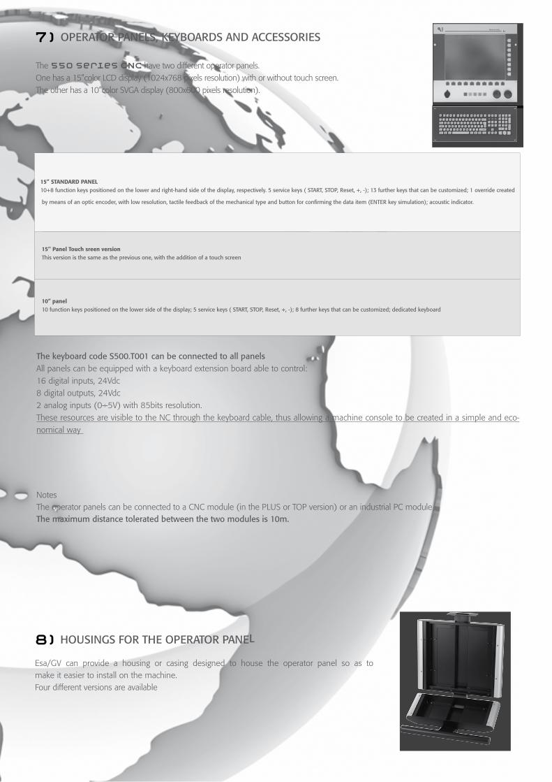
The 550 series CNC have two different operator panels. One has a 15”color LCD display (1024x768 pixels resolution) with or without touch screen. The other has a 10”color SVGA display (800x600 pixels resolution).
15” stAnDARD pAnel 10+8 function keys positioned on the lower and right-hand side of the display, respectively. 5 service keys ( START, STOP, Reset, +, -); 13 further keys that can be customized; 1 override created
by means of an optic encoder, with low resolution, tactile feedback of the mechanical type and button for confirming the data item (ENTER key simulation); acoustic indicator.
15’’ panel touch sreen versionThis version is the same as the previous one, with the addition of a touch screen
10” panel 10 function keys positioned on the lower side of the display; 5 service keys ( START, STOP, Reset, +, -); 8 further keys that can be customized; dedicated keyboard
The keyboard code S500.T001 can be connected to all panels All panels can be equipped with a keyboard extension board able to control:16 digital inputs, 24Vdc8 digital outputs, 24Vdc2 analog inputs (0÷5V) with 85bits resolution.These resources are visible to the NC through the keyboard cable, thus allowing a machine console to be created in a simple and eco-nomical way
NotesThe operator panels can be connected to a CNC module (in the PLUS or TOP version) or an industrial PC moduleThe maximum distance tolerated between the two modules is 10m.
8)
HOuSINGS FOR
THE
OPERATOR
PANEl
Esa/GV can provide a housing or casing designed to house the operator panel so as to
make it easier to install on the machine. Four different versions are available
housing code CRp.s500.001
Made of aluminum and sheet metal designed to house the operator panel with 15” display only
housing code CRp.s500.002Version similar to the previous one, with a housing for a keyboard (S500.T001), push buttons or electro-mechanical selectors, or a simple machine console, using the keyboard’s extension boards
housing code CRp.s500.003 Made of aluminum and sheet metal designed to house the operator panel with 10” display only
housing code CRp.s500.004 Version similar to the previous one, with a housing for a keyboard, push buttons or electro-mechanical selectors, or a simple machine console, using the keyboard’s extension boards
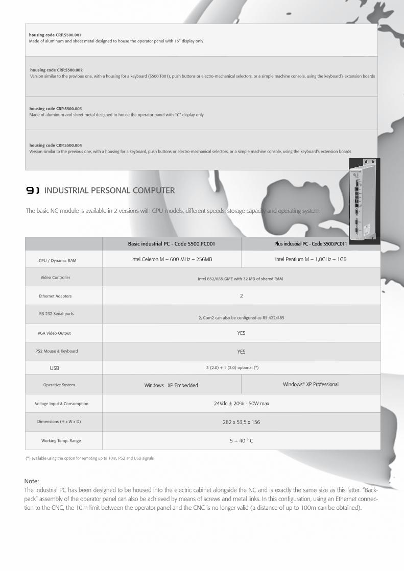
9) INDuSTRIAl PERSONAl COMPuTER
The basic NC module is available in 2 versions with CPU models, different speeds, storage capacity and operating system
Basic industrial PC - Code S500.PC001 Plus industrial PC - Code S500.PC011
CPu / Dynamic RAM Intel Celeron M – 600 MHz – 256MB Intel Pentium M – 1,8GHz – 1GB
Video Controller Intel 852/855 GME with 32 MB of shared RAM
Ethernet Adapters 2
RS 232 Serial ports2, Com2 can also be configured as RS 422/485
VGA Video Output YES
PS2 Mouse & Keyboard YES
USB 3 (2.0) + 1 (2.0) optional (*)
Operative System Windows XP Embedded Windows® XP Professional
Voltage Input & Consumption 24Vdc ± 20% - 50W max
Dimensions (H x W x D) 282 x 53,5 x 156
Working Temp. Range 5 ÷ 40 ° C
(*) available using the option for remoting up to 10m, PS2 and USB signals
Note:The industrial PC has been designed to be housed into the electric cabinet alongside the NC and is exactly the same size as this latter. “Back-pack” assembly of the operator panel can also be achieved by means of screws and metal links. In this configuration, using an Ethernet connec-tion to the CNC, the 10m limit between the operator panel and the CNC is no longer valid (a distance of up to 100m can be obtained).

10) N.C. / P.C. CONNECTION
The basic CNC and the PC can only be connected by means of a serial link.It is advisable to connect the CNC Plus and TOP and the PC via Ethernet, even though use of the serial link continues to be possi-ble. To avoid conflicts between the CNC connection and the corporate network to which our system must be linked, all Esa/Gv’s
550 Series industrial PC are equipped with 2 network ports as part of the standard equipment.

Typical applicationsl Conventional press-brakes (Mechanical and Hydraulic), Synchro
Hydraulic Press-brakes, Servo controlled hydraulic single cylin-der press-brakes, Electrically driven press-brakes, Tandem press-brakes
l Hydro-mechanical press-brakes American style l Hämmerle press-brakel Guillotine shears, with 3-4 axesl Four rolls plate bending, with trapezoidal or orbital geometry
SHEET METAl FORMING APPlICATIONS
Software featuresl Interactive 2D & 3D graphic editor for work-pieces and tools data
entryl Imports tools description and work-pieces programs from the most
common file format (dxf ...)l 3D graphic display and animation of machine frame, work-piece
and toolsl 2D & 3D automatic identification of the best bending sequencel Programming of the axes positions in tabular mode with automatic
syntactical checks, automatic calculation of the R and Z positions and of the bending and crowning tonnage
l Windows XP® Professional operating systeml Complete off-line programming on a standard PC, trough a simula-
tion programl IEC 61131-3 PLC programming language with function utilities ei-
ther written in IL or “C” language are available for manufacturersl Customizable alarm messages
Special featuresl Selectable and programmable axes and auxiliary functionsl Drivers for hydraulic axes with proportional valves or servo valves,
servo drivers (a.c./d.c.), and a.c. motors with or without inver-ter; drivers for the most common field buses (Sercos, CANopen, Mechatrolink, ESALink...)
l Following arms, thickness detector, in-process angle measurement units, robotic interfacing, controlling for tandem press-brakes
l Safety PLC communication (PILZ, LAZER SAFE)l Modem for telecommunication assistancel Remote handheld terminal for editing and correctional opera-
tionsl Connection to external electronic goniometer and calibrel Management of several sensors inputs for measuring sizes like
material thickness and width or resistance; measuring the machi-ne frame deformation and so on
l Angle corrections databasel Dynamic crowning managementl In-process angle measurement unit managementl High performances tandem machines management without ad-
ded sensors requirementl USB memory stick available on all products rangel Fully hardware and software compatibility among all products rangel USB memory stick available on all products rangel CNC hardware configuration (motors type & quantity, valves
type & quantity, I/O type & quantity) can be edited from the CNC itself