co 2 capture from flue gas using amino acid salt solutions benedicte mai lerche kaj thomsen &...
TRANSCRIPT
CO2 Capture from Flue Gas using
Amino Acid Salt Solutions
Benedicte Mai Lerche
Kaj Thomsen & Erling H. Stenby

2
Chemical absorption
Topic: Amino acid salt solutions as solvent for the process

3
Solvent properties
Volatility StabilityCO2 absorption rate
CO2 solubility
CO2 desorption ability
CO2 loading (mol CO2/mol amine) CO2 capacity (mol CO2/Kg solution)
4
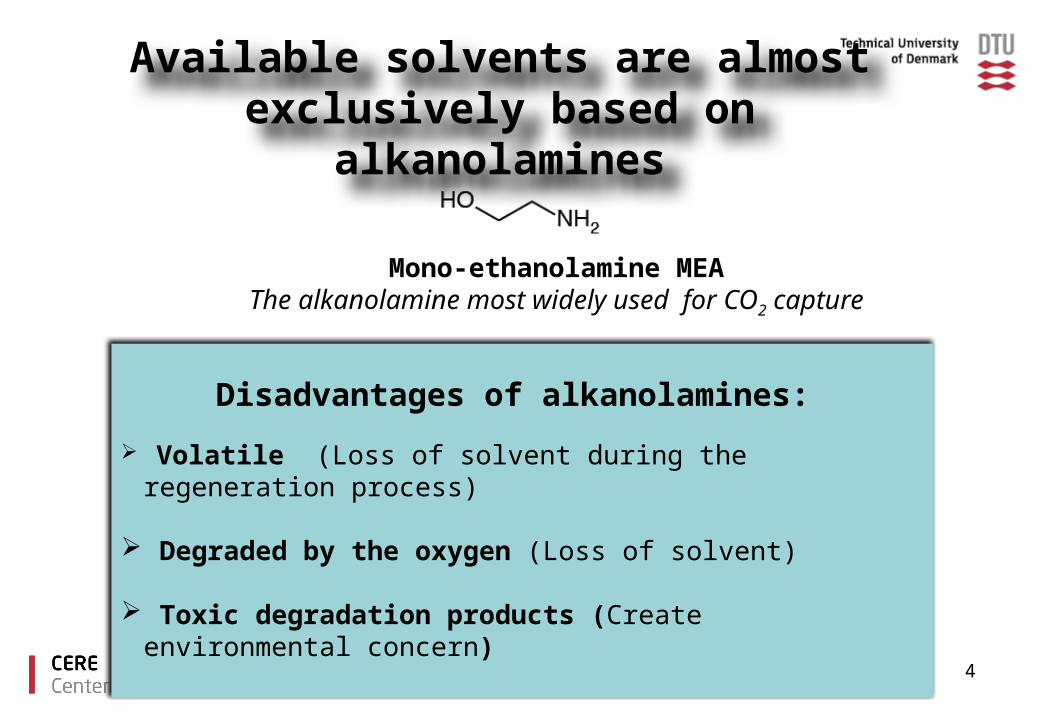
Available solvents are almost exclusively based on alkanolamines
Disadvantages of alkanolamines:
Volatile (Loss of solvent during the regeneration process)
Degraded by the oxygen (Loss of solvent)
Toxic degradation products (Create environmental concern)
Mono-ethanolamine MEAThe alkanolamine most widely used for CO2 capture

5
Amino acid salt solutions are alternatives to alkanolamines
Advantages of amino acid salt solution: Low volatility High stability towards oxidative degradation Environmentally friendly (naturally present)
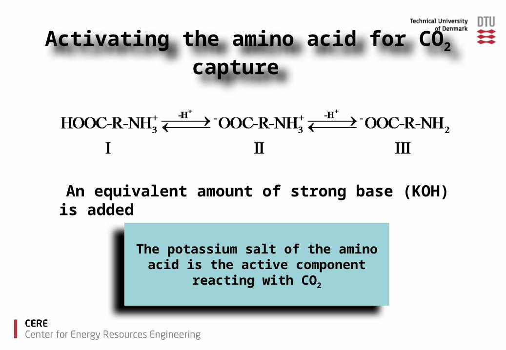
Activating the amino acid for CO2 capture
The potassium salt of the amino acid is the active component reacting with CO2
An equivalent amount of strong base (KOH) is added

7
CO2 reacts with amino acid salt solutions similar to alkanolamines
The absorption rate is dominated by carbamate formation

8
Precipitation
Precipitation of the reaction products can occur with high amino acid salt concentration at high CO2 loading
Precipitation offers certain interesting opportunities as well as drawbacks:
Opportunities: Increase of CO2 loading capacity
Drawbacks: plugging of the equipment.

9
Selecting amino acid salt solutions for CO2 capture
Solubility
Heat stability
CO2 loading
Cyclic absorption & regeneration

Amino acids Studied
Glycine
Proline Lysine
Taurine
11
Solubility
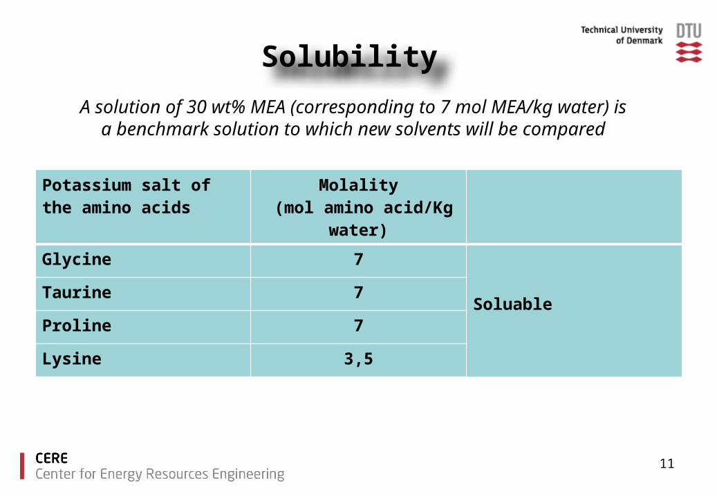
Potassium salt of the amino acids
Molality (mol amino acid/Kg water)
Glycine 7 Soluable
Taurine 7
Proline 7
Lysine 3,5
A solution of 30 wt% MEA (corresponding to 7 mol MEA/kg water) is a benchmark solution to which new solvents will be compared
12
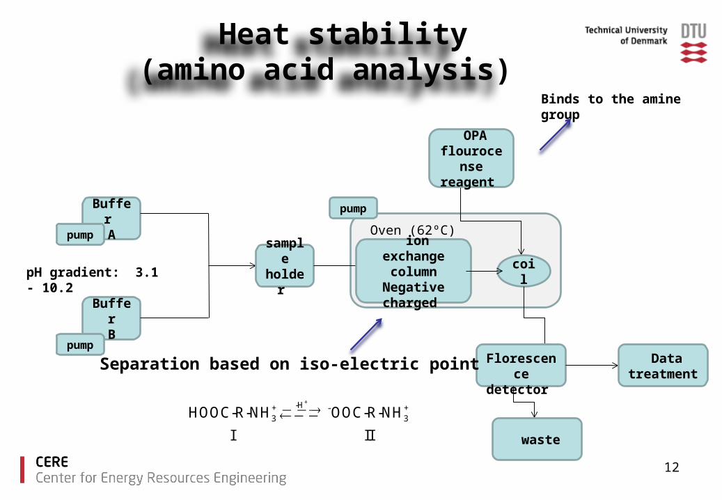
Heat stability (amino acid analysis)
Buffer A
BufferB
sampleholder
pump
pump
ion exchange column
Negative charged
Oven (62ºC)
OPA flourocense
reagent
coil
pump
Florescence detector
Datatreatment
waste
pH gradient: 3.1 - 10.2
Separation based on iso-electric point
Binds to the amine group
+-H+ - +3 3HOOC-R-NH OOC-R-NH
I II

13
Heat stability results
Amino acids salt solutions were heated for 24 hours at 120 ºC The degree of degradation is found by comparing heated to non
heated samples.
14
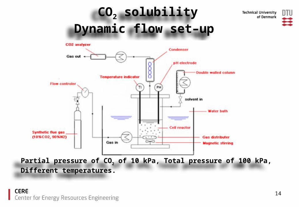
CO2 solubility Dynamic flow set–up
Partial pressure of CO2 of 10 kPa, Total pressure of 100 kPa, Different temperatures.

15
Validating Equipment at 40 ºC
[1]. Leila Faramarzi, Georgios M. Kontogeorgis, Kaj Thomsen, Erling H. Stenby, “Extended UNIQUAC model for thermodynamic modeling of CO2 absorption in aqueous alkanolamine solutions” Fluid Phase Equilibria, 2009,vol. 282 pp. 121–132

16
Validating Equipment at 40 ºC
17
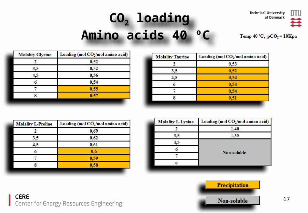
CO2 loading Amino acids 40 ºC

18
CO2 loading 40 ºC

19
Glycine 40 ºC
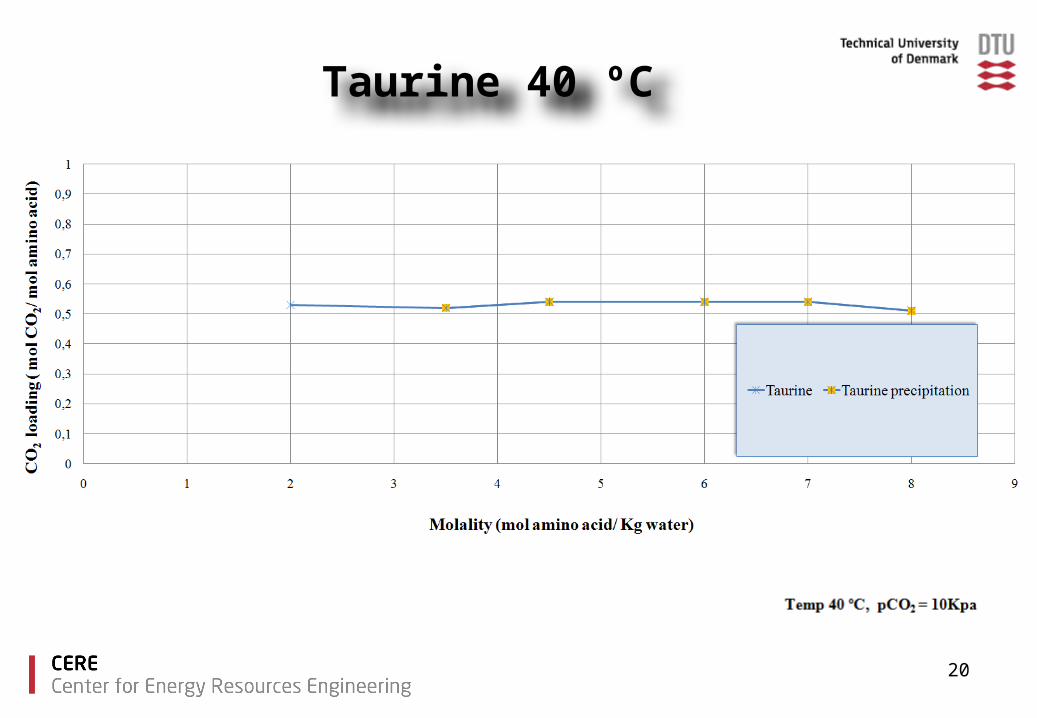
Taurine 40 ºC
20
21
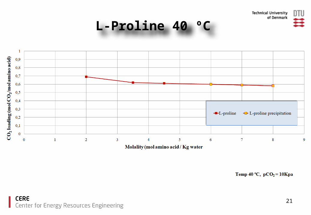
L-Proline 40 ºC

22
CO2 capacity

23
Conclusions
The amino acids tested showed good CO2 loading capacities compared to MEA.
With increased amino acid salt concentration precipitation was observed for glycine, taurine and proline.
There is no increase in CO2 loading capacity due to precipitation under the experimental conditions used.
Lysine offers high CO2 capacity without precipitation.
24
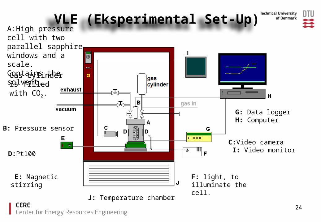
VLE (Eksperimental Set-Up)A:High pressure cell with two parallel sapphire windows and a scale.Contains the solvent.
B: Pressure sensor
C:Video camera I: Video monitor
D:Pt100
G: Data logger H: Computer
J: Temperature chamber
F: light, to illuminate the cell.
E: Magnetic stirring
Gas cylinder is filled with CO2.
25
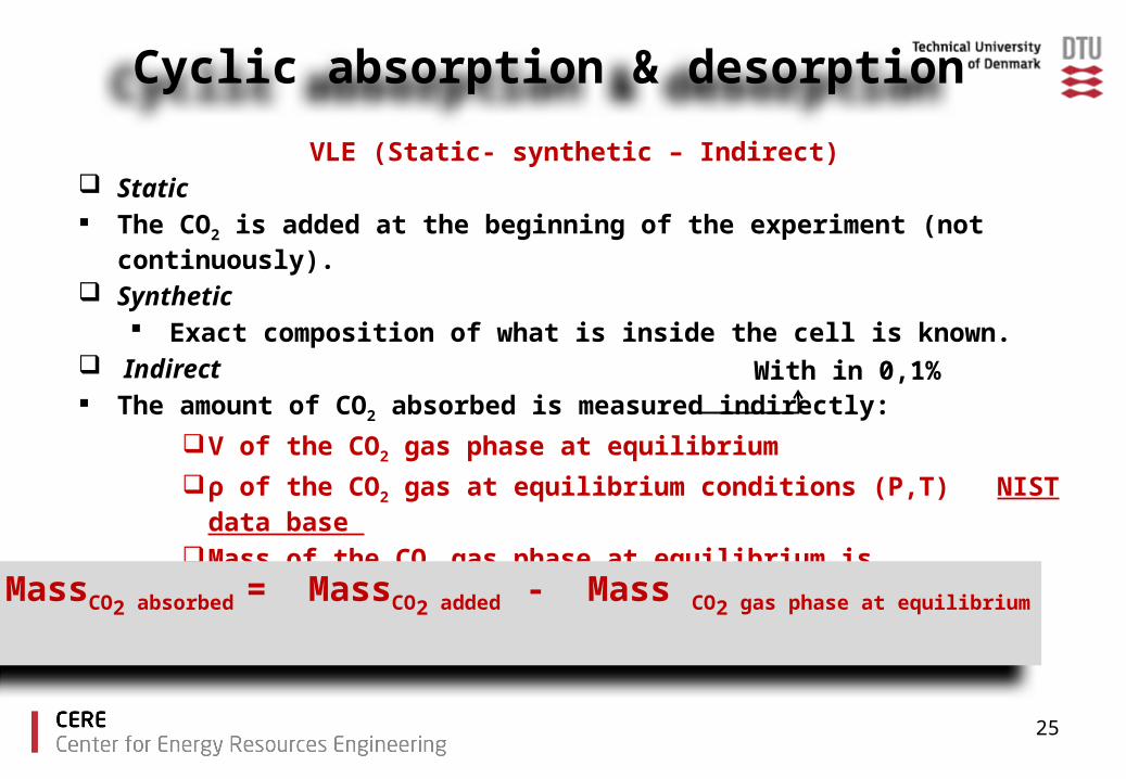
Cyclic absorption & desorption
VLE (Static- synthetic – Indirect) Static The CO2 is added at the beginning of the experiment (not continuously).
Synthetic Exact composition of what is inside the cell is known.
Indirect The amount of CO2 absorbed is measured indirectly:
V of the CO2 gas phase at equilibrium
ρ of the CO2 gas at equilibrium conditions (P,T) NIST data base
Mass of the CO2 gas phase at equilibrium is calculated .
MassCO2 absorbed = MassCO2 added - Mass CO2 gas phase at equilibrium
With in 0,1%
26
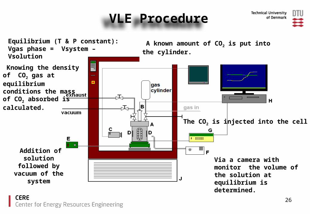
A known amount of CO2 is put into the cylinder.
Addition of solution followed by vacuum
of the systemVia a camera with monitor the volume of the solution at equilibrium is determined.
Equilibrium (T & P constant):Vgas phase = Vsystem – Vsolution
Knowing the density of CO2 gas at equilibrium conditions the mass of CO2 absorbed is calculated.
The CO2 is injected into the cell
VLE Procedure

27
Thank you for your attention!