coatings for turbine blades
TRANSCRIPT
8/7/2019 Coatings for Turbine Blades
http://slidepdf.com/reader/full/coatings-for-turbine-blades 1/26
Coatings for Turbine Blades
Introductiono Mapo Historyo The_Gas_Turbineo Materialso Degradationo Coatings
Bond_Coatso Introductiono Aluminideso Pt-Aluminideso MCrAlY
TBCo Introductiono Materials
Processeso Introductiono Thermal_Sprayo EBPVD
In_Practiceo Coatings_in_practice
Resourceso Bibliographyo Links
Historical overview
Only some 60 years after the invention of the jet engines, flying has become aconventional method of transportation. Once the exclusive privilege of the`swagger rich', it has become as much of a commonplace as a bus trip to the citycentre (and in fact, the comfort and service onboard some of the cheapestairlines push the analogy further).
Yet, back in the early 1940's, many were seeing jet-powered flight as no morethan a `laboratory experiment' (maybe in the same way as we may be, today,sceptical about future applications of the recent `scramjet').
Engr. Salman Ali SyedSaudi Electricity Company
Abha-Saudi Arabia
8/7/2019 Coatings for Turbine Blades
http://slidepdf.com/reader/full/coatings-for-turbine-blades 2/26
These doubts were not unfounded: materials used in parts of the engine couldnot survive more than a few hundred hours at then relatively modesttemperatures.
By the 1950's however, jet fighters were first put in combat in the sky of Korea. Atthe end of the 1960's, commercial jets were accepted, and by the end of the1980's, the commercial aviation market overtook the military one.
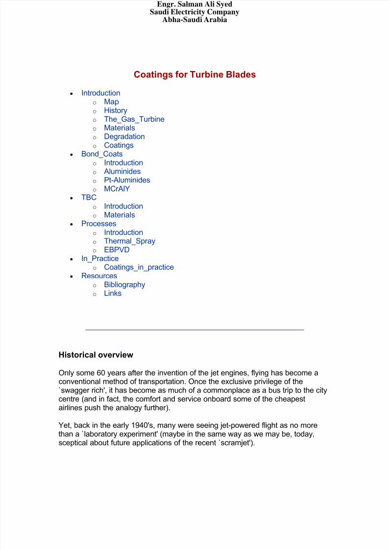
The efficiency of commercial airliners has increased beyond all earlyexpectations, and while it would probably be unfair to single out one factor,improvements in engine materials certainly played a key role.
r Pratt & Withney. Obtained from this page. Increase in operational temperature of turbine components.Techn.7:2003, p73-80.
Economical and, today, environmental concerns continue to provide impetus for operating the engines at ever increasing temperatures, thereby improving thethermodynamic efficiency and reducing pollutant emissions.
In its early years, the quest for higher temperatures was dominated by materialsand processes developments. The apparition of superalloys in the early 1950's,considerable amelioration in casting technologies and, in the 1960's, the cooling
Engr. Salman Ali SyedSaudi Electricity Company
Abha-Saudi Arabia
8/7/2019 Coatings for Turbine Blades
http://slidepdf.com/reader/full/coatings-for-turbine-blades 3/26
system for turbine blades were all major steps forward, each allowing the servicetemperature to be increased by 20
oC or more.
Over the past 20-30 years, alloy improvement, directional and single-crystalsolidification have contributed significantly, but, arguably, the emphasis has beenshifted to coating systems which have allowed an increase of gas temperature of up to 110
oC.
Coatings in gas turbine serve a variety of purposes, whether in jet engines, land-based power generation turbines or marine engines. A first requirement tooperate turbines at higher temperatures was, of course, improved strength.Unfortunately, these conditions also mean severe oxidation/corrosion problems,and to make things worse, the improvement in mechanical properties of the basealloys was made at the expense of environmental resistance.
The first purpose of coatings was therefore to palliate for the poor oxidationresistance of the base alloy (aluminide, Pt-aluminide, MCrAlY). A second type of coatings applied to high-temperature parts are known as thermal barrier coatings(TBC). These are ceramic coatings with very low thermal conductivity. Despitebeing typically 1/5 mm thin, the allow for a drop of 100-300 oC between the gasand metal surface temperatures. Such coatings, however, are `oxygentransparent' and do not prevent oxidation of the underlying substrate.
The gas turbine
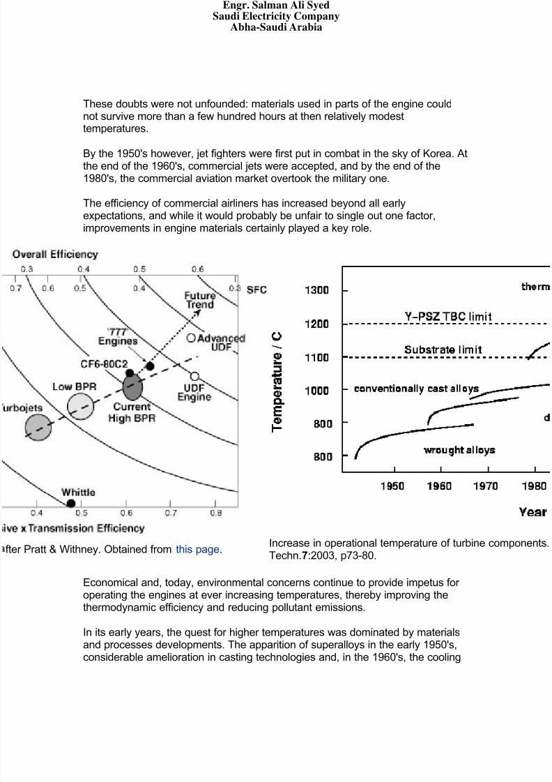
To discuss the role and use of coatings, it is necessary to first have a look at agas turbine (below, a jet engine) and get an idea of the different problems thematerials encounter.
Engr. Salman Ali SyedSaudi Electricity Company
Abha-Saudi Arabia
8/7/2019 Coatings for Turbine Blades
http://slidepdf.com/reader/full/coatings-for-turbine-blades 4/26
A jet engine (Rolls-Royce Trent 800), showing the differentstages: intermediate pressure compressor (IPC), high pressurecompressor (HPC), high pressure turbine (HPT), intermediatepressure turbine (IPT), low pressure turbine (LPT), and thepressure and temperature profiles along the engine.Image of the Trent 800 courtesy Rolls-Royce Plc. Diagrams after Michael Cervenka, Rolls-Royce.
An excellent and simple description of the functioning of a jet engine can be
found on the Rolls-Royce website: Journey through a jet engine. GeneralElectrics also has a slightly more detailed yet fun demo.
Land-based gas turbines as used in the power generation industry are inprinciple very similar, but larger, and the actual turbine (the last rows of blades inthe engine) is not connected with the rest of the engine, but drives a generator. Insome cases however, a first turbine does drive the compressor, while a second isconnected to a generator (power generation) or power shaft (marine engine).
Engr. Salman Ali SyedSaudi Electricity Company
Abha-Saudi Arabia

8/7/2019 Coatings for Turbine Blades
http://slidepdf.com/reader/full/coatings-for-turbine-blades 5/26
A gas turbine for marine propulsion, with a two-stage turbine, the first onedriving the compressor, the second providing the power. From this page
Materials in the gas turbine
As visible in the temperature and pressure profile on the last page, the conditionsin the gas turbine vary widely. Different materials are therefore chose for differentparts, as illustrated below:
Engr. Salman Ali SyedSaudi Electricity Company
Abha-Saudi Arabia
8/7/2019 Coatings for Turbine Blades
http://slidepdf.com/reader/full/coatings-for-turbine-blades 6/26
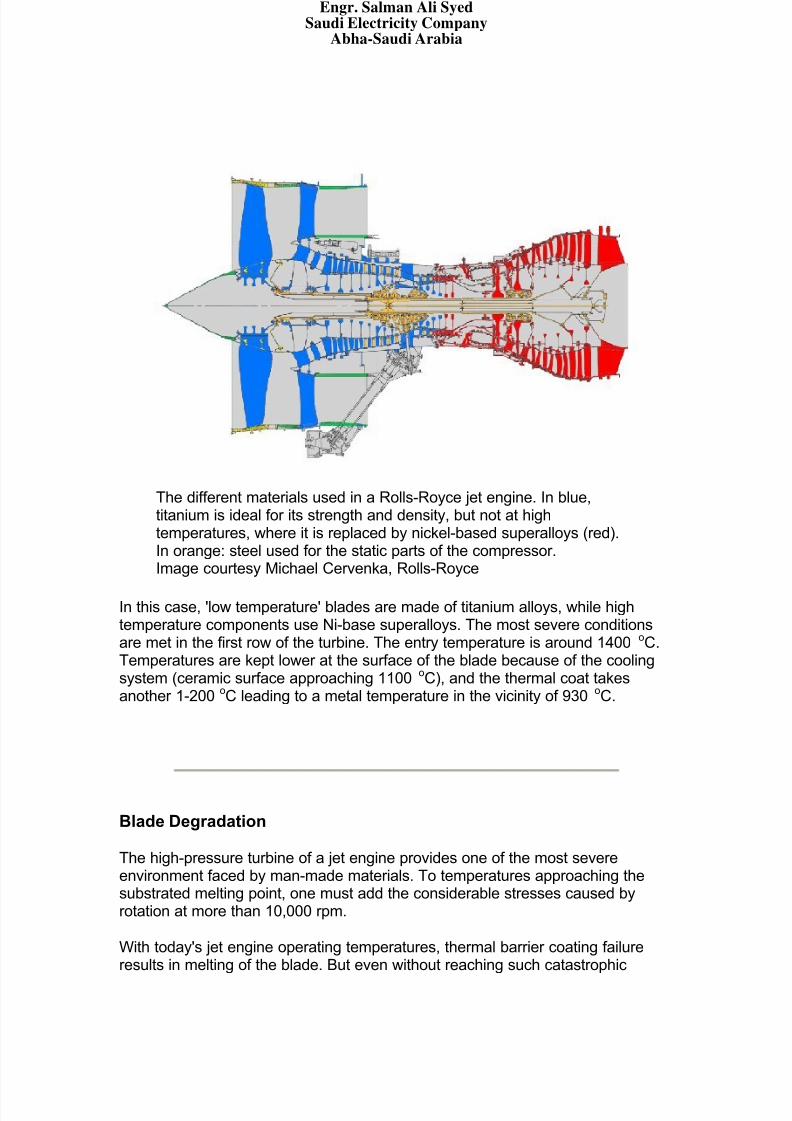
The different materials used in a Rolls-Royce jet engine. In blue,titanium is ideal for its strength and density, but not at hightemperatures, where it is replaced by nickel-based superalloys (red).In orange: steel used for the static parts of the compressor.Image courtesy Michael Cervenka, Rolls-Royce
In this case, 'low temperature' blades are made of titanium alloys, while hightemperature components use Ni-base superalloys. The most severe conditionsare met in the first row of the turbine. The entry temperature is around 1400 oC.Temperatures are kept lower at the surface of the blade because of the coolingsystem (ceramic surface approaching 1100
oC), and the thermal coat takes
another 1-200oC leading to a metal temperature in the vicinity of 930
oC.
Blade Degradation
The high-pressure turbine of a jet engine provides one of the most severeenvironment faced by man-made materials. To temperatures approaching thesubstrated melting point, one must add the considerable stresses caused byrotation at more than 10,000 rpm.
With today's jet engine operating temperatures, thermal barrier coating failureresults in melting of the blade. But even without reaching such catastrophic
Engr. Salman Ali SyedSaudi Electricity Company
Abha-Saudi Arabia
8/7/2019 Coatings for Turbine Blades
http://slidepdf.com/reader/full/coatings-for-turbine-blades 7/26
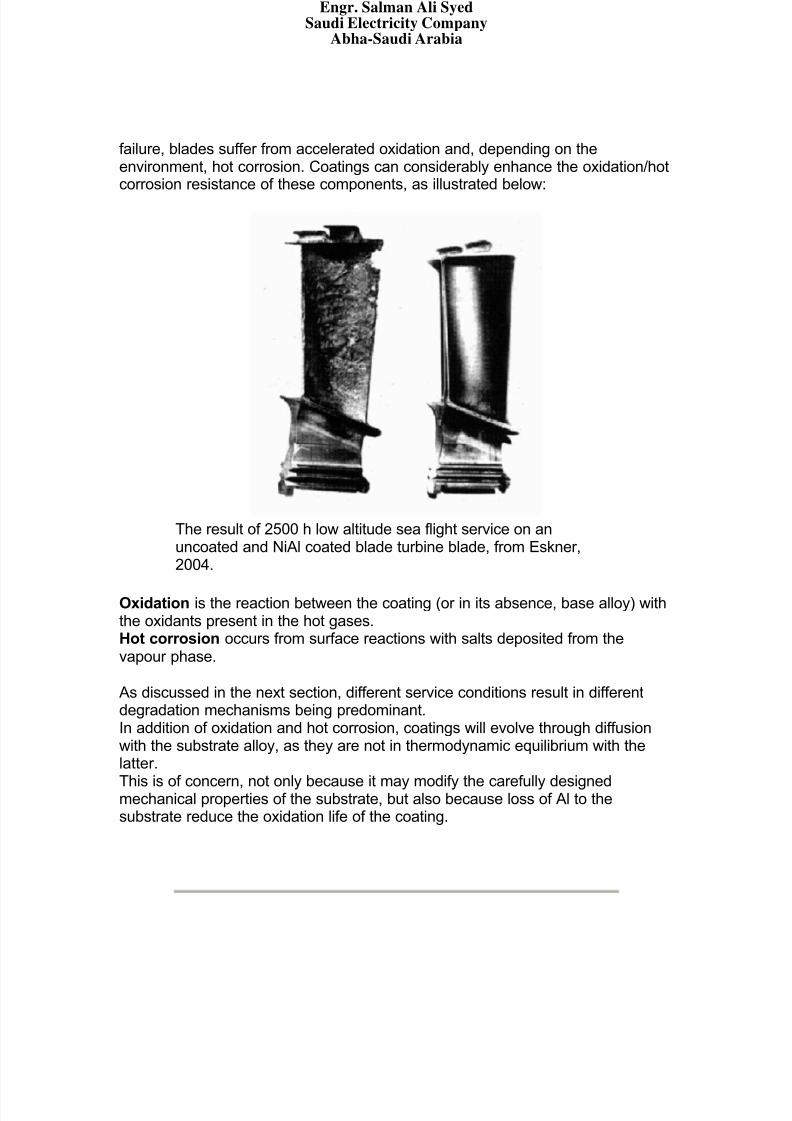
failure, blades suffer from accelerated oxidation and, depending on theenvironment, hot corrosion. Coatings can considerably enhance the oxidation/hotcorrosion resistance of these components, as illustrated below:
The result of 2500 h low altitude sea flight service on anuncoated and NiAl coated blade turbine blade, from Eskner,2004.
Oxidation is the reaction between the coating (or in its absence, base alloy) withthe oxidants present in the hot gases.Hot corrosion occurs from surface reactions with salts deposited from thevapour phase.
As discussed in the next section, different service conditions result in differentdegradation mechanisms being predominant.In addition of oxidation and hot corrosion, coatings will evolve through diffusionwith the substrate alloy, as they are not in thermodynamic equilibrium with thelatter.
This is of concern, not only because it may modify the carefully designedmechanical properties of the substrate, but also because loss of Al to thesubstrate reduce the oxidation life of the coating.
Engr. Salman Ali SyedSaudi Electricity Company
Abha-Saudi Arabia
8/7/2019 Coatings for Turbine Blades
http://slidepdf.com/reader/full/coatings-for-turbine-blades 8/26
Coatings
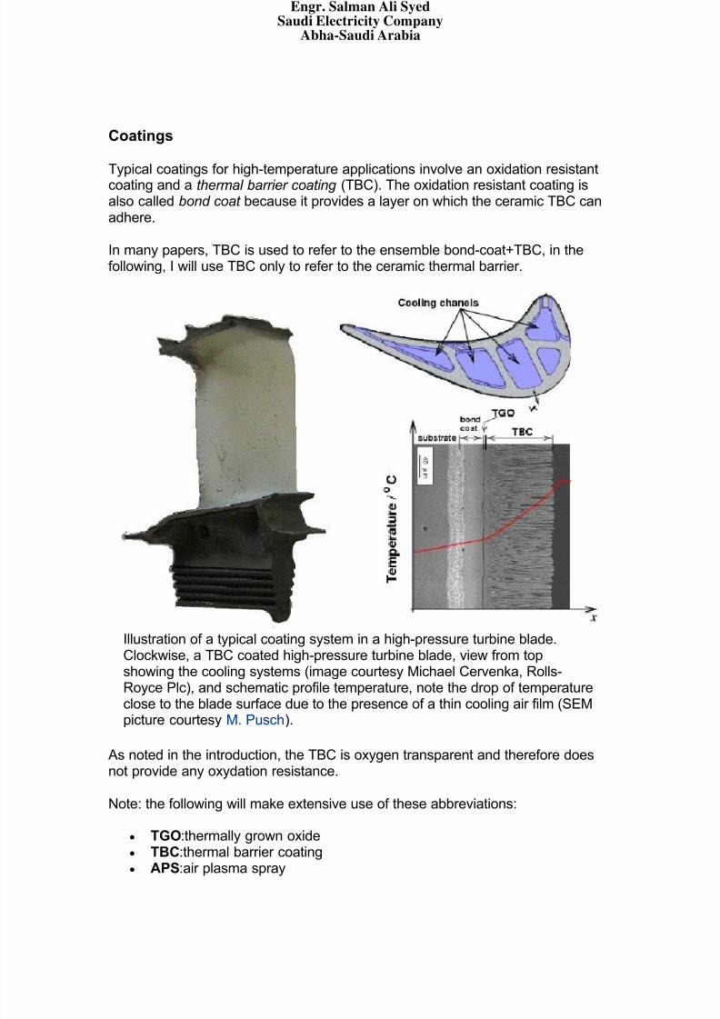
Typical coatings for high-temperature applications involve an oxidation resistantcoating and a thermal barrier coating (TBC). The oxidation resistant coating isalso called bond coat because it provides a layer on which the ceramic TBC canadhere.
In many papers, TBC is used to refer to the ensemble bond-coat+TBC, in thefollowing, I will use TBC only to refer to the ceramic thermal barrier.
Illustration of a typical coating system in a high-pressure turbine blade.Clockwise, a TBC coated high-pressure turbine blade, view from topshowing the cooling systems (image courtesy Michael Cervenka, Rolls-Royce Plc), and schematic profile temperature, note the drop of temperatureclose to the blade surface due to the presence of a thin cooling air film (SEMpicture courtesy M. Pusch).
As noted in the introduction, the TBC is oxygen transparent and therefore doesnot provide any oxydation resistance.
Note: the following will make extensive use of these abbreviations:
TGO:thermally grown oxide TBC:thermal barrier coating APS:air plasma spray
Engr. Salman Ali SyedSaudi Electricity Company
Abha-Saudi Arabia

8/7/2019 Coatings for Turbine Blades
http://slidepdf.com/reader/full/coatings-for-turbine-blades 9/26
LPPS:low pressure plasma spray EBPVD:electron beam physical vapour deposition
Bond coats::Introduction
The following table compares the severity of the different surface-relatedproblems for gas turbine applications:
oxidation hotcorrosion interdiffusion thermalfatigue
Aircraftengines
severe moderate severe severe
Land-basedpower
generationmoderate severe moderate light
Marineengines
moderate severe light moderate
Comparison of problems for gas turbine applications, after F.S. Pettit and
G. W. Goward, Coatings for High Temperature Applications, AppliedScience Publishers, 1983
Recent generations of superalloys for single crystal turbine blades containrelatively high percentages of refractory elements such as Ta, W or Re whichenhance the high-temperature mechanical properties (Chen, 1997).
This, however, is done at the expense of Cr and Al. Given the severeenvironmental conditions in which the blades operate, the removal of theelements (beneficial for oxidation resistance) implies even greater degradationproblems.
To palliate for this lack of appropriate oxidation.corrosion resistance, an externalcoating is applied to the blades. Its purpose is to allow for the growth of aresistant oxide layer. Of all possible oxides, α-Al2O3 offers excellent protectionand very low growth rates (in a minority of cases, Cr oxides are preferred). Thecomposition of the coating must therefore be chosen carefully so as to ensuregrowth of α-Al2O3.
Engr. Salman Ali SyedSaudi Electricity Company
Abha-Saudi Arabia
8/7/2019 Coatings for Turbine Blades
http://slidepdf.com/reader/full/coatings-for-turbine-blades 10/26
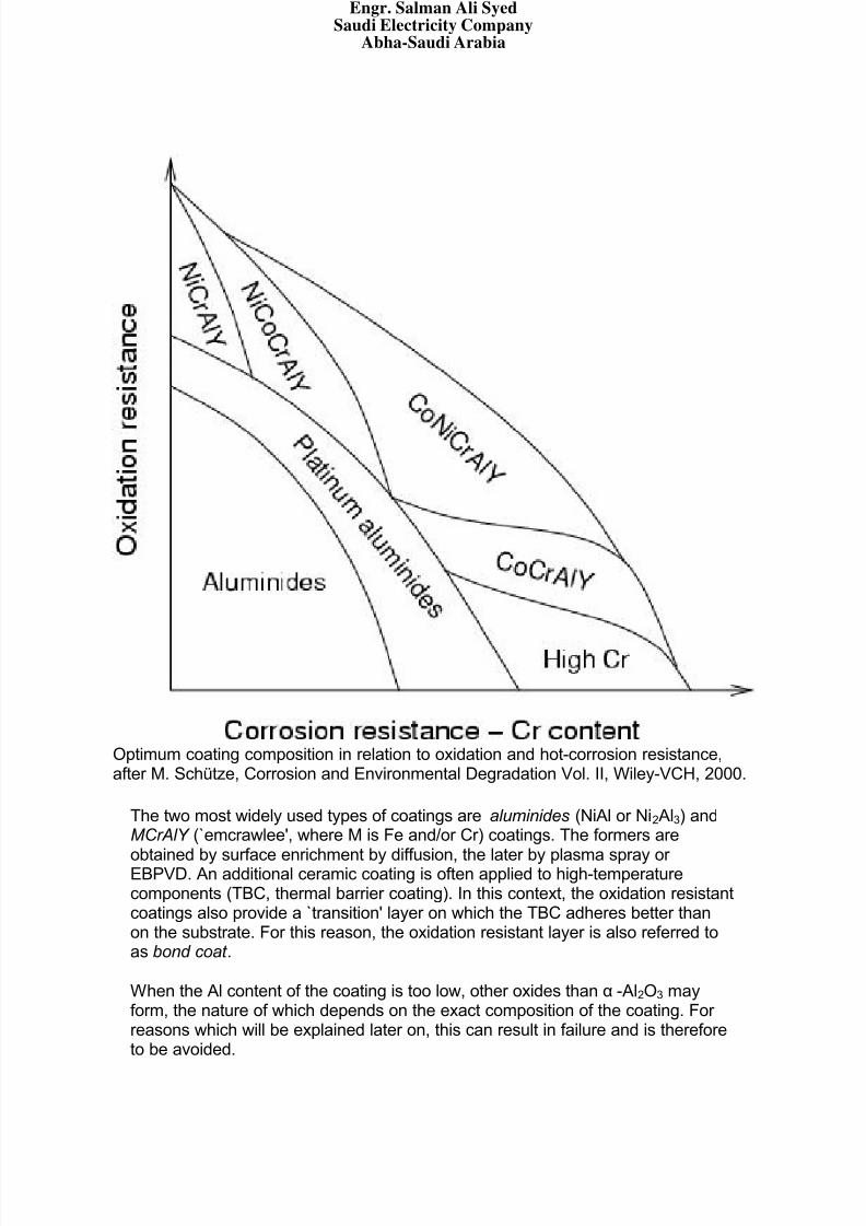
Optimum coating composition in relation to oxidation and hot-corrosion resistance,after M. Schütze, Corrosion and Environmental Degradation Vol. II, Wiley-VCH, 2000.
The two most widely used types of coatings are aluminides (NiAl or Ni2Al3) andMCrAlY (`emcrawlee', where M is Fe and/or Cr) coatings. The formers are
obtained by surface enrichment by diffusion, the later by plasma spray or EBPVD. An additional ceramic coating is often applied to high-temperaturecomponents (TBC, thermal barrier coating). In this context, the oxidation resistantcoatings also provide a `transition' layer on which the TBC adheres better thanon the substrate. For this reason, the oxidation resistant layer is also referred toas bond coat .
When the Al content of the coating is too low, other oxides than α-Al2O3 mayform, the nature of which depends on the exact composition of the coating. For reasons which will be explained later on, this can result in failure and is thereforeto be avoided.
Engr. Salman Ali SyedSaudi Electricity Company
Abha-Saudi Arabia
8/7/2019 Coatings for Turbine Blades
http://slidepdf.com/reader/full/coatings-for-turbine-blades 11/26
Blade integrity is now critically dependent on these coatings and possiblyadditional ceramic thermal barrier coatings. Unfortunately, `prime-reliability', theconcept of a coating whose life does no longer condition that of the blade, has
not been achieved yet. With the increasing cost of the blades themselves, thepractise of coating renewal has developed. In this operation, a gas turbine istaken apart, each blade is dismantled, its surface cleaned and a new coatingapplied.
With, on one hand, the prospect of coating failure leading to catastrophic bladeloss, and on the other hand an extremely expensive maintenance process, it isno surprise that much research is dedicated to improving the evaluation of remnant life.
Bond coats::Aluminides
In modern applications involving very high temperatures or severe hot corrosionproblems, aluminide coatings provide relatively limited protection. They arenevertheless still widely used in less demanding applications.
Consitution
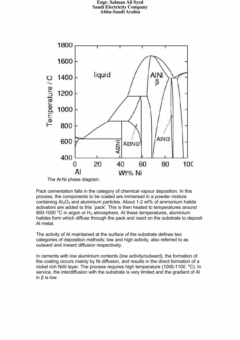
Diffusion aluminide coatings are based on the intermetallic compound β-NiAl(see phase diagram). Although different processes exist to form them, packcementation is the most widely used as it is inexpensive and well adapted tocoating of small parts.
Engr. Salman Ali SyedSaudi Electricity Company
Abha-Saudi Arabia
8/7/2019 Coatings for Turbine Blades
http://slidepdf.com/reader/full/coatings-for-turbine-blades 12/26
The Al-Ni phase diagram.
Pack cementation falls in the category of chemical vapour deposition. In thisprocess, the components to be coated are immersed in a powder mixturecontaining Al2O3 and aluminium particles. About 1-2 wt% of ammonium halideactivators are added to this `pack'. This is then heated to temperatures around800-1000
oC in argon or H2 atmosphere. At these temperatures, aluminium
halides form which diffuse through the pack and react on the substrate to depositAl metal.
The activity of Al maintained at the surface of the substrate defines two
categories of deposition methods: low and high activity, also referred to asoutward and inward diffusion respectively.
In cements with low aluminium contents (low activity/outward), the formation of the coating occurs mainly by Ni diffusion, and results in the direct formation of anickel rich NiAl layer. The process requires high temperature (1000-1100 oC). Inservice, the interdiffusion with the substrate is very limited and the gradient of Alin β is low.
Engr. Salman Ali SyedSaudi Electricity Company
Abha-Saudi Arabia
8/7/2019 Coatings for Turbine Blades
http://slidepdf.com/reader/full/coatings-for-turbine-blades 13/26
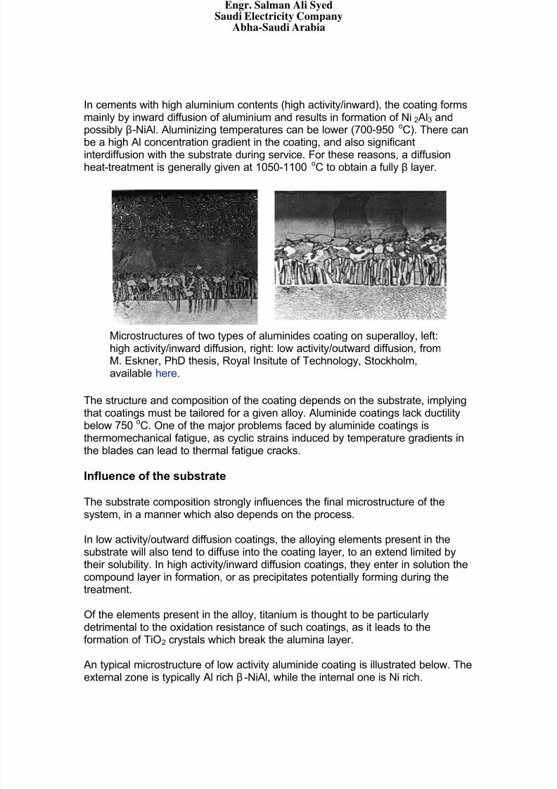
In cements with high aluminium contents (high activity/inward), the coating formsmainly by inward diffusion of aluminium and results in formation of Ni2Al3 andpossibly β-NiAl. Aluminizing temperatures can be lower (700-950 oC). There canbe a high Al concentration gradient in the coating, and also significantinterdiffusion with the substrate during service. For these reasons, a diffusionheat-treatment is generally given at 1050-1100
oC to obtain a fully β layer.
Microstructures of two types of aluminides coating on superalloy, left:high activity/inward diffusion, right: low activity/outward diffusion, fromM. Eskner, PhD thesis, Royal Insitute of Technology, Stockholm,available here.
The structure and composition of the coating depends on the substrate, implying
that coatings must be tailored for a given alloy. Aluminide coatings lack ductilitybelow 750
oC. One of the major problems faced by aluminide coatings is
thermomechanical fatigue, as cyclic strains induced by temperature gradients inthe blades can lead to thermal fatigue cracks.
Influence of the substrate
The substrate composition strongly influences the final microstructure of thesystem, in a manner which also depends on the process.
In low activity/outward diffusion coatings, the alloying elements present in the
substrate will also tend to diffuse into the coating layer, to an extend limited bytheir solubility. In high activity/inward diffusion coatings, they enter in solution thecompound layer in formation, or as precipitates potentially forming during thetreatment.
Of the elements present in the alloy, titanium is thought to be particularlydetrimental to the oxidation resistance of such coatings, as it leads to theformation of TiO2 crystals which break the alumina layer.
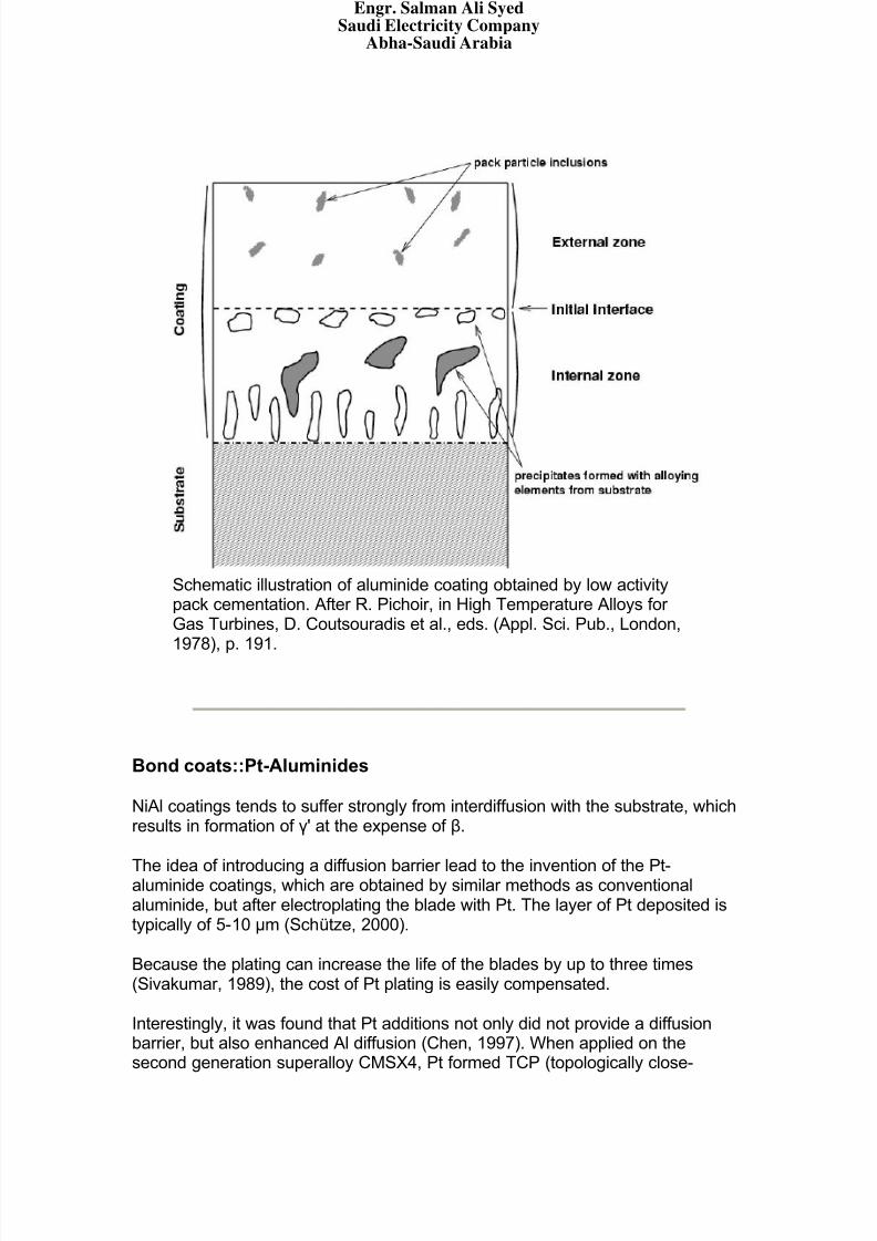
An typical microstructure of low activity aluminide coating is illustrated below. Theexternal zone is typically Al rich β-NiAl, while the internal one is Ni rich.
Engr. Salman Ali SyedSaudi Electricity Company
Abha-Saudi Arabia
8/7/2019 Coatings for Turbine Blades
http://slidepdf.com/reader/full/coatings-for-turbine-blades 14/26
Schematic illustration of aluminide coating obtained by low activitypack cementation. After R. Pichoir, in High Temperature Alloys for Gas Turbines, D. Coutsouradis et al., eds. (Appl. Sci. Pub., London,
1978), p. 191.
Bond coats::Pt-Aluminides
NiAl coatings tends to suffer strongly from interdiffusion with the substrate, whichresults in formation of γ' at the expense of β.
The idea of introducing a diffusion barrier lead to the invention of the Pt-aluminide coatings, which are obtained by similar methods as conventionalaluminide, but after electroplating the blade with Pt. The layer of Pt deposited istypically of 5-10 μm (Schütze, 2000).
Because the plating can increase the life of the blades by up to three times(Sivakumar, 1989), the cost of Pt plating is easily compensated.
Interestingly, it was found that Pt additions not only did not provide a diffusionbarrier, but also enhanced Al diffusion (Chen, 1997). When applied on thesecond generation superalloy CMSX4, Pt formed TCP (topologically close-
Engr. Salman Ali SyedSaudi Electricity Company
Abha-Saudi Arabia
8/7/2019 Coatings for Turbine Blades
http://slidepdf.com/reader/full/coatings-for-turbine-blades 15/26
packed) phases with some elements of the substrate (Re, W, Mo, Cr).The exact reasons for the beneficial effect of Pt are not fully understood, but itwas found that Pt improves oxide adherence and also contributes to better hot
corrosion resistance.
Pt appears to partially substitute Ni in β-NiAl, and also to form PtAl2 which isbelieved to act as an Al reservoir. It has also been proposed that Pt acts in asimilar manner as Y in MCrAlY coatings. In these coatings, Y combines with S;this greatly increase the coating life as S is otherwise detrimental to theadherence of the oxide layer. There is nevertheless no evidence of a similar effect of Pt in β-NiAl coatings (Evans, 2001).
Bond coats::MCrAlY
Introduction
As discussed in previous sections, aluminide coatings strongly interact with thesubstrates and must therefore be tailored for each different alloy.
Overlay coatings as opposed to diffusion coatings, provide more independencefrom the substrate alloy, but also more flexibility in design as compositions canbe modified depending on the degradation mechanisms expected to prevail.Typical MCrAlY bond coats (M=Fe,Co or Ni) contain at least 4 elements, whichmeans that coating methods such as pack cementation are considerably moredifficult to use, as the activity of each element in the pack would have to becontrolled carefully so as to obtain a coating of required composition.
The presence of a significant amount of Cr give these coatings excellentcorrosion resistance combined with good oxidation resistance.
Alternative methods are therefore preferred, such as air plasma spray (APS), lowpressure plasma spray (LPPS), or electron beam physical vapour deposition(EBPVD). These are detailed in other sections. Deposition is followed by a high-temperature heat-treatment in vacuum to allow interdiffusion and thereforeimprove adhesion (for example, Richard 1996) .
Microstructure
MCrAlY coatings typically exhibit a two-phase microstructure β+γ. The presenceof γ increases the ductility of the coating thereby improving thermal fatigueresistance.
Engr. Salman Ali SyedSaudi Electricity Company
Abha-Saudi Arabia
8/7/2019 Coatings for Turbine Blades
http://slidepdf.com/reader/full/coatings-for-turbine-blades 16/26
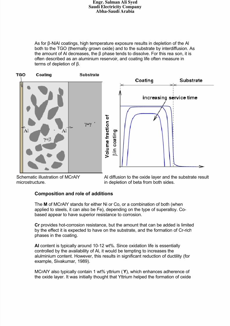
As for β-NiAl coatings, high temperature exposure results in depletion of the Alboth to the TGO (thermally grown oxide) and to the substrate by interdiffusion. Asthe amount of Al decreases, the β phase tends to dissolve. For this reason, it isoften described as an aluminium reservoir, and coating life often measure interms of depletion of β.
Schematic illustration of MCrAlYmicrostructure.
Al diffusion to the oxide layer and the substrate resultin depletion of beta from both sides.
Composition and role of additions
The M of MCrAlY stands for either Ni or Co, or a combination of both (whenapplied to steels, it can also be Fe), depending on the type of superalloy. Co-based appear to have superior resistance to corrosion.
Cr provides hot-corrosion resistance, but the amount that can be added is limited
by the effect it is expected to have on the substrate, and the formation of Cr-richphases in the coating.
Al content is typically around 10-12 wt%. Since oxidation life is essentiallycontrolled by the availability of Al, it would be tempting to increases thealulminium content. However, this results in significant reduction of ductility (for example, Sivakumar, 1989).
MCrAlY also typically contain 1 wt% yttrium ( Y), which enhances adherence of the oxide layer. It was initially thought that Yttrium helped the formation of oxide
Engr. Salman Ali SyedSaudi Electricity Company
Abha-Saudi Arabia
8/7/2019 Coatings for Turbine Blades
http://slidepdf.com/reader/full/coatings-for-turbine-blades 17/26
8/7/2019 Coatings for Turbine Blades
http://slidepdf.com/reader/full/coatings-for-turbine-blades 18/26
with large residual compression in the underlying thermally grown oxide (TGO),but details of the mechanism only begin to be understood (Evans et al., 2001).
TBC materials
For a ceramic coating to have any chance not to spall at the first thermal cycle, itis critical that its thermal expansion be close to that of the substrate.For the coating to be of use, it must also exhibit a very low thermal conductivity.
For this purpose, yttria(Y2O3)-stabilised zirconia(ZrO2) (YSZ) is widely used. Theaddition of 5-15% yttria stabilises the zirconia in its high-temperature crystallineform, therefore avoiding phase-transition in the range of service temperatures.
Zirconia (ZrO2) based ceramics satisfy both requirements, with a thermalexpansion coefficient of 11-13x10
-6K
-1and a thermal conductivity of about 2.3
W/(m.K) at 1000oC for a fully dense material, this can be further reduced by
introducing porosity (Evans, 2001)
The very low thermal conductivity of YSZ is due to the presence of a highconcentration of point defects which scatter lattice vibrations (Padture, 2002)
Thermal barrier coatings can be obtained by different processes, such aselectron beam physical vapour deposition (EBPVD) or air plasma spray (APS).These techniques are described in another section. Different techniques result insignificantly different microstructure. Although more costly than APS, EBPVD isthe preferred method for high-pressure turbine blades, as these result in amicrostructure which considerably enhances the strain tolerance:
Engr. Salman Ali SyedSaudi Electricity Company
Abha-Saudi Arabia
8/7/2019 Coatings for Turbine Blades
http://slidepdf.com/reader/full/coatings-for-turbine-blades 19/26
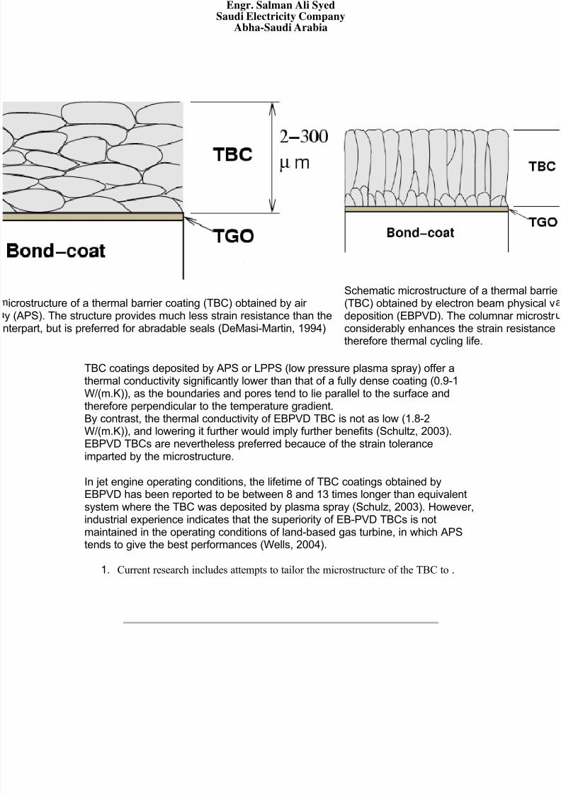
rostructure of a thermal barrier coating (TBC) obtained by air APS). The structure provides much less strain resistance than therpart, but is preferred for abradable seals (DeMasi-Martin, 1994)
Schematic microstructure of a thermal barrie(TBC) obtained by electron beam physical vdeposition (EBPVD). The columnar microstr considerably enhances the strain resistancetherefore thermal cycling life.
TBC coatings deposited by APS or LPPS (low pressure plasma spray) offer athermal conductivity significantly lower than that of a fully dense coating (0.9-1W/(m.K)), as the boundaries and pores tend to lie parallel to the surface andtherefore perpendicular to the temperature gradient.
By contrast, the thermal conductivity of EBPVD TBC is not as low (1.8-2W/(m.K)), and lowering it further would imply further benefits (Schultz, 2003).EBPVD TBCs are nevertheless preferred becauce of the strain toleranceimparted by the microstructure.
In jet engine operating conditions, the lifetime of TBC coatings obtained byEBPVD has been reported to be between 8 and 13 times longer than equivalentsystem where the TBC was deposited by plasma spray (Schulz, 2003). However,industrial experience indicates that the superiority of EB-PVD TBCs is notmaintained in the operating conditions of land-based gas turbine, in which APStends to give the best performances (Wells, 2004).
1. Current research includes attempts to tailor the microstructure of the TBC to.
Engr. Salman Ali SyedSaudi Electricity Company
Abha-Saudi Arabia
8/7/2019 Coatings for Turbine Blades
http://slidepdf.com/reader/full/coatings-for-turbine-blades 20/26
Deposition processes
There is a large number of competing processes for coating surfaces, and only afew of them will be presented in the next sections, which are the most relevant tothe application of overlay coatings (MCrAlY) or TBC.
Coating processes can be broadly divided in methods by which atoms attachindividually to the surface, or methods which apply particles. Physical vapour deposition (PVD) or chemical vapour deposition (CVD) are examples of theformer. Thermal spraying methods fall in the second category.
An example of CVD has been described earlier (aluminides coatings by packcementation)
The following sections give a very brief overview of the following processes:
Thermal spraying: air plasma spray (APS), low pressure plasma spray(LPPS), high velocity oxyfuel spray (HVOF) etc .
Electron-beam PVD (EBPDV).
thermal spray methods
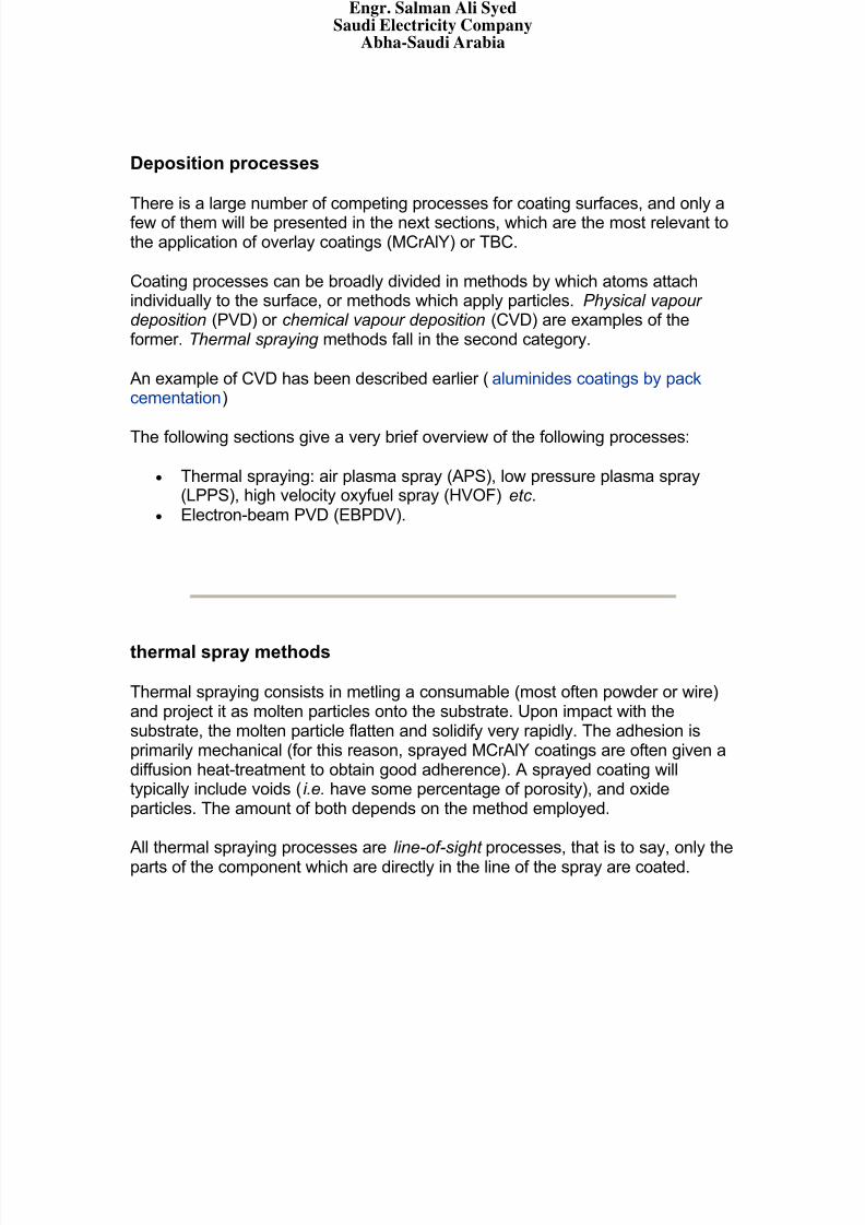
Thermal spraying consists in metling a consumable (most often powder or wire)and project it as molten particles onto the substrate. Upon impact with thesubstrate, the molten particle flatten and solidify very rapidly. The adhesion isprimarily mechanical (for this reason, sprayed MCrAlY coatings are often given adiffusion heat-treatment to obtain good adherence). A sprayed coating willtypically include voids (i.e. have some percentage of porosity), and oxideparticles. The amount of both depends on the method employed.
All thermal spraying processes are line-of-sight processes, that is to say, only theparts of the component which are directly in the line of the spray are coated.
Engr. Salman Ali SyedSaudi Electricity Company
Abha-Saudi Arabia
8/7/2019 Coatings for Turbine Blades
http://slidepdf.com/reader/full/coatings-for-turbine-blades 21/26
Schematic microstructure of thermal spray coating, showing only a few layers of particles.
The adhesion of the coating depends on the cleanliness of the substrate surface,and its area (a high surface roughness is desirable for good adhesion), on thevelocity of the particles, etc .
There are various types of thermal spraying methods, some of which are brieflyintroduced:
Flame spraying: the first method employed uses an oxyacetylene flame(about 2700 \degc) to melt and project the coating, fed as wire, rod or powder. Typical particle velocity is about 40 m/s, porosity 10-15 %,identical oxide content, for a deposition rate of 1 to 10 kg/h.
Plasma spraying: similar but uses a ionised gas plasma to melt andpropel the coating (powder), temperature of the plasma can exceed16,000 \degc, while the substrate itself will seldom heat beyond 150 \degc.Particle velocity can reach 200-300 m/s, the porosity is reduced to 5-10 %,the oxide content to 1-3 % for deposition rates of 1-5 kg/h.
High velocity oxyfuel(HVOF): spraying uses oxygen and hydrogen with afuel gas such as methane, particle velocity ranges between 600-1000 m/s,oxide and porosity are reduced to 1-2 % for a deposition rate similar tothat of plasma spray.
Engr. Salman Ali SyedSaudi Electricity Company
Abha-Saudi Arabia
8/7/2019 Coatings for Turbine Blades
http://slidepdf.com/reader/full/coatings-for-turbine-blades 22/26
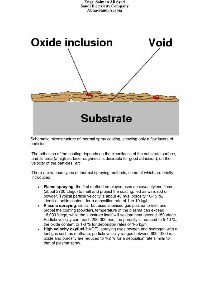
A couple of interesting variants of the conventional plasma spraying are knownas low pressure plasma spraying (LPPS) and vacuum plasma spray (VPS),which, as indicated by their names, are identical to plasma spraying except for itbeing done in inert gas at low pressure, or in vacuum. This reduces slowing andcooling the particles by air, and avoids oxidation during spraying. The traditionalmethod is usually referred to as APS (air plasma spray).
Schematic illustration plasma torch.
APS and LPPS are widely used to apply MCrAlY coatings. TBCs can also beapplied by this method. In the case of jet engine operation conditions, it has beenshown that the use of EBPVD increases by 7 to 13 times the life of the coating,therefore easily compensating for the higher cost of the latter process. In thecase of land-based power generation, APS TBCs last up to twice the life of EBPVD coatings, although the reason is not clearly understood (Wells, 2004).
Electron beam physical vapour deposition
As indicated by its name, electron beam physical vapour deposition belongs tothe more general category of physical vapour deposition.
In these methods, film growth is obtained by condensation of a vapour on thesubstrate. The vapour can be produced by heating the consumable enough toobtain evaporation, or by mechanically knocking the atoms off (e.g. sputtering).
In EB-PVD, the evaporation is obtained with a focused electron beam, asillustrated below.
Engr. Salman Ali SyedSaudi Electricity Company
Abha-Saudi Arabia
8/7/2019 Coatings for Turbine Blades
http://slidepdf.com/reader/full/coatings-for-turbine-blades 23/26
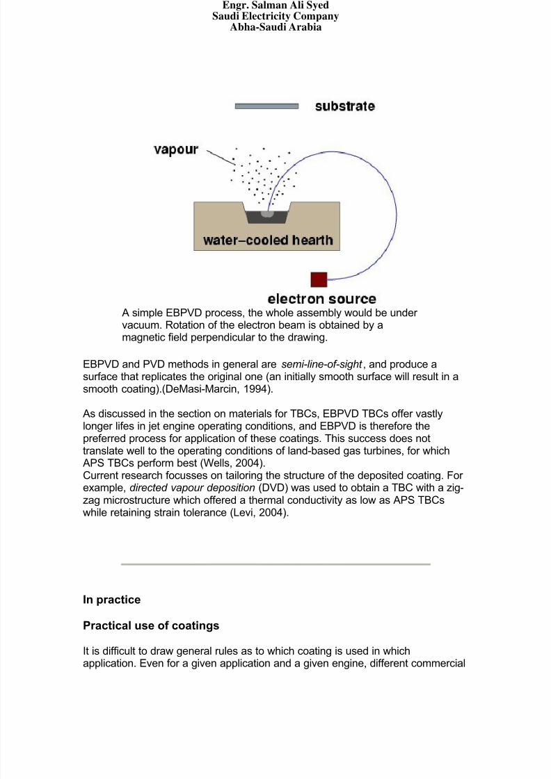
A simple EBPVD process, the whole assembly would be under vacuum. Rotation of the electron beam is obtained by amagnetic field perpendicular to the drawing.
EBPVD and PVD methods in general are semi-line-of-sight , and produce asurface that replicates the original one (an initially smooth surface will result in asmooth coating).(DeMasi-Marcin, 1994).
As discussed in the section on materials for TBCs, EBPVD TBCs offer vastlylonger lifes in jet engine operating conditions, and EBPVD is therefore thepreferred process for application of these coatings. This success does nottranslate well to the operating conditions of land-based gas turbines, for whichAPS TBCs perform best (Wells, 2004).Current research focusses on tailoring the structure of the deposited coating. For example, directed vapour deposition (DVD) was used to obtain a TBC with a zig-zag microstructure which offered a thermal conductivity as low as APS TBCswhile retaining strain tolerance (Levi, 2004).
In practice
Practical use of coatings
It is difficult to draw general rules as to which coating is used in whichapplication. Even for a given application and a given engine, different commercial
Engr. Salman Ali SyedSaudi Electricity Company
Abha-Saudi Arabia
8/7/2019 Coatings for Turbine Blades
http://slidepdf.com/reader/full/coatings-for-turbine-blades 24/26
strategies may imply different choice of coatings: opting for a higher efficiencyand therefore higher temperatures at the expense of long life means that theoperating conditions are changed, and the dominant degradation mechanisms
may be different.
Jet engines and land based power generation turbines provide differentenvironments. In general, jet engines high pressure turbine blades (HPT blades)are expected to last for about 30,000 h. For land-based power generation, thisfigure can vary between 50,000 and 75,000 h (about 9 years).HPT blades in jet engine will typically undergo one refurbishment (strip coatingand re-coat) throughout their life; in power generation applications, one or tworefurbishments depending on the target life.
At the time of writing (2004), rough estimates of costs provided by RWE Innogy
are (power generation):
set of blades for HPT: 1.5 million gbp cost of refurbishment: variable: 0.3 to 1 million gbp.
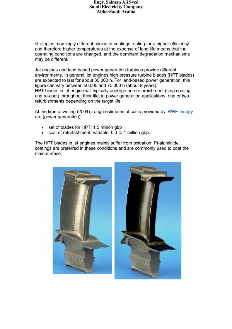
The HPT blades in jet engines mainly suffer from oxidation; Pt-aluminidecoatings are preferred in these conditions and are commonly used to coat themain surface.
Engr. Salman Ali SyedSaudi Electricity Company
Abha-Saudi Arabia
8/7/2019 Coatings for Turbine Blades
http://slidepdf.com/reader/full/coatings-for-turbine-blades 25/26
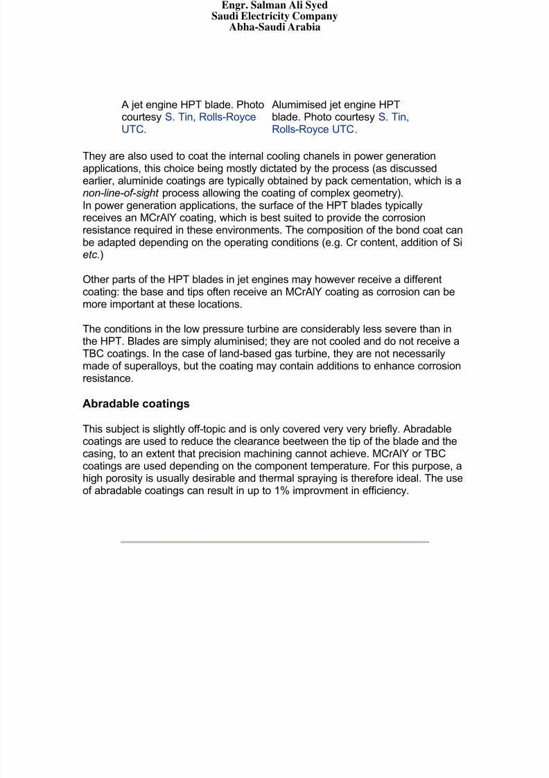
A jet engine HPT blade. Photocourtesy S. Tin, Rolls-RoyceUTC.
Alumimised jet engine HPTblade. Photo courtesy S. Tin,Rolls-Royce UTC.
They are also used to coat the internal cooling chanels in power generationapplications, this choice being mostly dictated by the process (as discussedearlier, aluminide coatings are typically obtained by pack cementation, which is anon-line-of-sight process allowing the coating of complex geometry).In power generation applications, the surface of the HPT blades typicallyreceives an MCrAlY coating, which is best suited to provide the corrosionresistance required in these environments. The composition of the bond coat canbe adapted depending on the operating conditions (e.g. Cr content, addition of Sietc .)
Other parts of the HPT blades in jet engines may however receive a differentcoating: the base and tips often receive an MCrAlY coating as corrosion can bemore important at these locations.
The conditions in the low pressure turbine are considerably less severe than inthe HPT. Blades are simply aluminised; they are not cooled and do not receive aTBC coatings. In the case of land-based gas turbine, they are not necessarilymade of superalloys, but the coating may contain additions to enhance corrosionresistance.
Abradable coatings
This subject is slightly off-topic and is only covered very very briefly. Abradablecoatings are used to reduce the clearance beetween the tip of the blade and thecasing, to an extent that precision machining cannot achieve. MCrAlY or TBCcoatings are used depending on the component temperature. For this purpose, ahigh porosity is usually desirable and thermal spraying is therefore ideal. The useof abradable coatings can result in up to 1% improvment in efficiency.
Engr. Salman Ali SyedSaudi Electricity Company
Abha-Saudi Arabia
8/7/2019 Coatings for Turbine Blades
http://slidepdf.com/reader/full/coatings-for-turbine-blades 26/26
Links
Informations on superalloys. applying abradable seals to industrial turbines comparison oxidation/thermal expansion various coatings analytical model Al depletion coating Liburdi Evaluation of Composition and Phases in Platinum Aluminide Diffusion
Coatings 18-Gas Turbine Technology Brochure Remnant life MAINTENANCE OF GAS TURBINES - IMPACT AND IMPliCATIONS
FOR Nli Life Assessment of a Jet Engine Component Advanced Diagnostics and Prognostics for Gas Turbine Engine Risk ... REPAIR AND COATING TECHNOLOGIES FOR NEW GAS TURBINE
BLADES GE Global Research 2002 Technical Reports THERMAL SPRAY COATINGS Thermal Barrier Coatings for the 21st Century 1 Degradation of EBPVD YSZ Thermal Barrier Coatings on Platinum
Aluminide Univercity Hompage Graphs Short Index of Propulsion Slides Aircraft Propulsion - Level 3 - Gas Turbine Operation and Design
Requirements (Gas Turbine Usage) Combustion Turbine The marine gas turbine: The emerging prime mover GE Transportation - Aircraft Engines: Engines 101 Platinum plating of gas turbine components A TRIBUTE TO A CAMBRIDGE ENGINEERINGSTUDENT Thermal Spray Abradable Coatings Physical Vapor Deposition EE150 Lecture - Physical Vapor Deposition Nature of Thermal Spray Coatings Surface Treatments: Thermal Spraying ICEBT | Advances in EB PVD Cover Story : Creating an Effective Barrier PVD Experimental Facilities Spraying - Wear-Management
Engr. Salman Ali SyedSaudi Electricity Company
Abha-Saudi Arabia