code for design of domestic ceramics plant
TRANSCRIPT

1
Pro fe s s io n a l S ta n da r d for L i g h t I n d u s try o f th e
Peo p l e ' s R e pu b l i c o f C h i na
Q B / T 6 0 1 7 - 2 0 2 0
R e p l a c e Q B / T 6 0 1 7 - 9 7
Code for design of domestic
ceramics plant (Draf t fo r approval )
I s s u e d o n 2 0 X X - X X - X X I m p l e m e n t e d o n 2 0 X X - X X X X
I s s ue d b y th e Min i s t r y o f I ndu s t ry a nd In fo r ma t i on
Te ch no log y o f th e P eop l e ' s Re pub l i c o f C h in a
I C S 8 1 . 0 6 0 . 0 1
P 8 8

2
Profess ional Standard for Light Industry of
the People ' s Republ ic o f China
Code for design of domestic
ceramics plant
QB/T 6017-2020
C h i e f d e v e l o p m e n t
d e p a r t m e n t :
M i n i s t r y o f I n d u s t r y a n d
I n f o r m a t i o n T e c h n o l o g y o f
t h e P e o p l e ' s R e p u b l i c o f
C h i n a
A p p r o v a l d e p a r t m e n t : M i n i s t r y o f I n d u s t r y a n d
I n f o r m a t i o n T e c h n o l o g y o f
t h e P e o p l e ' s R e p u b l i c o f
C h i n a
I m p l e m e n t a t i o n d a t e : X X m o n t h , X X d a y , X X y e a r
China XXXXXXXXXX
2 0 X X B e i j i n g

3
Announcement of the Ministry of
Industry and Information Technology of
the People's Republic of China
N o .
The Code for Design of Domestic Ceramics Plant is now approved as the
professional standard with a serial number of QB/T 6017-2020, which will be
implemented on November 1st,2020. The original Code for Design of Domestic
Ceramics Plant QB/T 6017-97 shall be abolished simultaneously.
This code is published and distributed by China Planning Press, which is
authorized by the Planning department of Ministry of Industry and Information
Technology.
Ministry of Industry and Information Technology of
the People's Republic of China
**month ** day, **year

1
Pr e fa c e
According to the requirements of the " The Notice of Printing and
Distributing the Revision Plan for the First Batch of Industry Standards in 2017 "
Ref. 40 (2017) issued by the General Office of the Ministry of Industry and
Information Technology, the development department revised this code after
making comprehensive investigation and study, summarizing the practical
experience, conducting extensive solicitation of opinions and referring to
relevant standard.
The technical contents of the code are comprised of 16 chapters: 1 General
provisions; 2 Terms and symbols;3 Location selection and general layout; 4
Process;5 Kiln;6 Fuel;7 Thermal power;8 Power supply;9Automatic control
instrument and information;10 Architecture and structure;11Water supply and
drainage; 12Heating ventilation and air conditioning;13 Fire fighting; 14
Engergy saving; 15 Enviromental Protection and 16 Occupational safety and
health.
The main contents of the revision of the code are as follows::
1. “Chapter 2 Terms and symbols”, “Chapter 14 Energy saving” and
“Chapter 16 Occupational Safety and health” are added.
2. The original “Chapter 2 General layout” is revised as “Chapter 3
Location selection and general layout”. Location selection related
content is added.
Q B / T 6 0 1 7— 2 0 2 0

2
3. The original Article 8 “Maintennance Workshop” of Chapter 3 is
deleted.
4. The provisions of original “Chapter 5 Fuel” has been substantially
deleted, and the provisions on clean fuel such as natural gas have been
added.
5. The original Chapter “Water supply and drainage amd fire fighting” is
split into two two chapters, namerly “Chapter 11 Water supply and
drainage” and “Chapter13 Fire fighting” .
6. The content of calculation of tunnel kiln length is deleted.
7. Article 4.7 “Packaging and warehousing workshop” and related
provisions have been added to “Chapter 4 Process”.
8. Contents that are not suitable for technological progress are modified
and adjusted.
9. In accordance with the relevant regulations and requirements in the
Provisions for the Compilation of Engineering Construction
Specifications, some of the provisions in the original code have been
modified and adjusted in writing.
The code development is supervised by the Planning Department of the
Ministry of Industry and Information Technology, authorized by China
Engineering Construction Association of Light Industry, and explained by China
CEC Engineering Corporation. The relevant opinions and advice in
implementation may be posted or passed on to China CEC Engineering

3
Corporation (Contact and address: No. 268, Xinxing Road, Yuhua District,
Changsha City, Hunan Province, Post Code: 410114; E-Mail:
Chief development department: China CEC Engienering Corporation
Participating development organization:
China Haisum Engineering Co., Ltd
Chengdu Engineering Co., Ltd of China Light Industry
Main drafting staff: Zhang Jianjun, Jiang Shanhong, Guo Qiang, Li Ning,
Yang Zehong, Yang Weixiang, Lei Ping, Cao Yu, Wang Shuyun, Hou
Yonggang, Zhang Yue and Rao Jia
Main reviewing staff: Qi Yongyi, Xu Jiaxin, Jin Fuming, Xu Lin, Chen
Baowu, Zhou Kaixiang, Yang Xiaozhen, Lin Hongyang, Rao Shengdi, Lu
Heming, Zhang Zhong, Luo Lilan, Ma Yunjie, Chen Jun and Li Xiaohong.
4
T a b l e o f c o n t e n t s
1 G e n e r a l p r o v i s i o n . . . . . . . . . . . . . . . . . . . . . . . . . . . . . . . . . . . . . . . . . . . . . . . . . . . . 7
2 T e r m s a n d s y m b o l s . . . . . . . . . . . . . . . . . . . . . . . . . . . . . . . . . . . . . . . . . . . . . . . . . . 8
2.1 T e r m i n o l o g y . . . . . . . . . . . . . . . . . . . . . . . . . . . . . . . . . . . . . . . . . . . . . . . . . . . . . . . 8
2.2 S y m b o l s . . . . . . . . . . . . . . . . . . . . . . . . . . . . . . . . . . . . . . . . . . . . . . . . . . . . . . . . . . . 1 0
3 L o c a t i o n s e l e c t i o n a n d g e n e r a l l a yo u t . . . . . . . . . . . . . . . . . . . . . . 1 2
3.1 Location selection. . . . . . . . . . . . . . . . . . . . . . . . . . . . . . . . . . . . . . . . . . . . . . . . . . . . 1 2
3.2 General layout . . . . . . . . . . . . . . . . . . . . . . . . . . . . . . . . . . . . . . . . . . . . . . . . . . . . . . . 1 2
3.3 Buildings and Structure arrangment. . . . . . . . . . . . . . . . . . . . . . . . . . . . . . . . . . 1 5
3.4 Passageway and roads . . . . . . . . . . . . . . . . . . . . . . . . . . . . . . . . . . . . . . . . . . . . . . . 2 1
3.5 Technical and economic indicators . . . . . . . . . . . . . . . . . . . . . . . . . . . . . . . . . . 2 2
4 P r o c e s s . . . . . . . . . . . . . . . . . . . . . . . . . . . . . . . . . . . . . . . . . . . . . . . . . . . . . . . . . . . . . . . . 2 5
4.1 General provisions . . . . . . . . . . . . . . . . . . . . . . . . . . . . . . . . . . . . . . . . . . . . . . . . . . . 2 5
4.2 Raw material workshop . . . . . . . . . . . . . . . . . . . . . . . . . . . . . . . . . . . . . . . . . . . . . . 2 6
4.3 Forming workshop . . . . . . . . . . . . . . . . . . . . . . . . . . . . . . . . . . . . . . . . . . . . . . . . . . . 2 9
4.4 Firing workshop . . . . . . . . . . . . . . . . . . . . . . . . . . . . . . . . . . . . . . . . . . . . . . . . . . . . . 3 2
4.5 Decorating Firing workshop . . . . . . . . . . . . . . . . . . . . . . . . . . . . . . . . . . . . . . . . . 3 4
4.6 Plaster moulding workshop . . . . . . . . . . . . . . . . . . . . . . . . . . . . . . . . . . . . . . . . . . 3 7
4.7 Packaging warehouse . . . . . . . . . . . . . . . . . . . . . . . . . . . . . . . . . . . . . . . . . . . . . . . . 3 8
4.8 Process piping . . . . . . . . . . . . . . . . . . . . . . . . . . . . . . . . . . . . . . . . . . . . . . . . . . . . . . . 3 9
5
4.9 Central laboratory and R&D center . . . . . . . . . . . . . . . . . . . . . . . . . . . . . . . . . . 4 3
5 K i l n . . . . . . . . . . . . . . . . . . . . . . . . . . . . . . . . . . . . . . . . . . . . . . . . . . . . . . . . . . . . . . . . . . . . 4 6
5.1 General provisions . . . . . . . . . . . . . . . . . . . . . . . . . . . . . . . . . . . . . . . . . . . . . . . . . . . 4 6
5.2 Kiln type selection . . . . . . . . . . . . . . . . . . . . . . . . . . . . . . . . . . . . . . . . . . . . . . . . . . . 4 6
5.3 Determination of main technical and ecomic index . . . . . . . . . . . . . . . . . . 4 6
6 F u e l . . . . . . . . . . . . . . . . . . . . . . . . . . . . . . . . . . . . . . . . . . . . . . . . . . . . . . . . . . . . . . . . . . . . 4 8
6.1 General provisions . . . . . . . . . . . . . . . . . . . . . . . . . . . . . . . . . . . . . . . . . . . . . . . . . . . 4 8
6.2 Fuel Gas . . . . . . . . . . . . . . . . . . . . . . . . . . . . . . . . . . . . . . . . . . . . . . . . . . . . . . . . . . . . . 4 8
6.3 Fuel oil . . . . . . . . . . . . . . . . . . . . . . . . . . . . . . . . . . . . . . . . . . . . . . . . . . . . . . . . . . . . . . . 4 9
7 T h e r m a l p o w e r . . . . . . . . . . . . . . . . . . . . . . . . . . . . . . . . . . . . . . . . . . . . . . . . . . . . . . 5 1
8 P o w e r S u p p l y . . . . . . . . . . . . . . . . . . . . . . . . . . . . . . . . . . . . . . . . . . . . . . . . . . . . . . . 5 3
9 A u t o m a t i c c o n t r o l i n s t r u m e n t a n d i n f o r m a t i o n . . . . . . . . . . 6 1
1 0 A r c h i t e c t u r e a n d S t r u c t u r e . . . . . . . . . . . . . . . . . . . . . . . . . . . . . . . . . 6 9
10.1 A r c h i t e c t u r e . . . . . . . . . . . . . . . . . . . . . . . . . . . . . . . . . . . . . . . . . . . . . . . . . . . . . 6 9
10.2 S t r u c t u r e . . . . . . . . . . . . . . . . . . . . . . . . . . . . . . . . . . . . . . . . . . . . . . . . . . . . . . . . . . 7 2
1 1 W a t e r S u p p l y a n d D r a i n a g e . . . . . . . . . . . . . . . . . . . . . . . . . . . . . . . . 7 5
1 2 H e a t i n g v e n t i l a t i o n a n d a i r c o n d i t i o n i n g . . . . . . . . . . . . . . 7 6
1 3 F i r e f i g h t i n g . . . . . . . . . . . . . . . . . . . . . . . . . . . . . . . . . . . . . . . . . . . . . . . . . . . . . 8 2
1 4 E n e r g y s a v i n g . . . . . . . . . . . . . . . . . . . . . . . . . . . . . . . . . . . . . . . . . . . . . . . . . . . 8 4
14.1 G e n e r a l p r o v i s i o n s . . . . . . . . . . . . . . . . . . . . . . . . . . . . . . . . . . . . . . . . . . . . 8 4
14.2 P r o c e s s e n e r g y s a v i n g . . . . . . . . . . . . . . . . . . . . . . . . . . . . . . . . . . . . . . . . 8 4
14.3 W a s t e h e a t r e c o v e r y . . . . . . . . . . . . . . . . . . . . . . . . . . . . . . . . . . . . . . . . . . 8 4

6
14.4 E l e c t r i c i t y s a v i n g . . . . . . . . . . . . . . . . . . . . . . . . . . . . . . . . . . . . . . . . . . . . . . 8 5
1 5 E n v i r o n m e n t a l P r o t e c t i o n . . . . . . . . . . . . . . . . . . . . . . . . . . . . . . . . . . . 8 7
15.1 G e n e r a l p r o v i s i o n s . . . . . . . . . . . . . . . . . . . . . . . . . . . . . . . . . . . . . . . . . . . . 8 7
15.2 W a s t e w a t e r . . . . . . . . . . . . . . . . . . . . . . . . . . . . . . . . . . . . . . . . . . . . . . . . . . . . . . 8 7
15.3 W a s t e g a s . . . . . . . . . . . . . . . . . . . . . . . . . . . . . . . . . . . . . . . . . . . . . . . . . . . . . . . . . 8 7
15.4 W a s t e s o l i d s . . . . . . . . . . . . . . . . . . . . . . . . . . . . . . . . . . . . . . . . . . . . . . . . . . . . . 8 8
15.5 N o i s e . . . . . . . . . . . . . . . . . . . . . . . . . . . . . . . . . . . . . . . . . . . . . . . . . . . . . . . . . . . . . . . 8 9
1 6 O c c u p a t i o n a l S a f e t y a n d H e a l t h . . . . . . . . . . . . . . . . . . . . . . . . . . 9 1
16.1 G e n e r a l r u l e s . . . . . . . . . . . . . . . . . . . . . . . . . . . . . . . . . . . . . . . . . . . . . . . . . . . . 9 1
16.2 F i r i n g a n d e x p l o s i v e p r e v e n t i n g . . . . . . . . . . . . . . . . . . . . . . . . . . 9 1
16.3 P r o t e c t i o n a g a i n s t m e c h a n i c a l i n j u r y . . . . . . . . . . . . . . . . . . . 9 1
16.4 L i g h t n i n g P r o t e c t i o n . . . . . . . . . . . . . . . . . . . . . . . . . . . . . . . . . . . . . . . . . . 9 2
16.5 P r o t e c t i o n a g a i n s t d u s t a n d t o x i c a n t s . . . . . . . . . . . . . . . . . . . 9 2
16.6 H e a t s t r o k e p r e v e n t i o n , c o o l i n g a n d h e a t i n g . . . . . . . . . . . 9 3
16.7 N o i s e c o n t r o l . . . . . . . . . . . . . . . . . . . . . . . . . . . . . . . . . . . . . . . . . . . . . . . . . . . . 9 3
A p p e n d i x A T h e t a b l e o f b u l k w e i g h t a n d i n t e r n a l f r i c t i o n
a n g l e f o r c o m m o n m a t e r i a l s i n d o m e s t i c c e r a m i c s p l a n t . 9 4
E x p l a n a t i o n o f t e r m s u s e d i n t h i s s p e c i f i c a t i o n . . . . . . . . . . . . . 9 6
L i s t o f Q u o t e d S t a n d a r d s . . . . . . . . . . . . . . . . . . . . . . . . . . . . . . . . . . . . . . . . . . . 9 7
R e v i s i o n n o t e
7
1 Ge n e ra l p rov i s i on
1.0.1 The standard is formulated to implement national laws and regulations,
technical and economic policies as well as project relevant engineering codes, to
promote clean production, and to realize the objectives of advanced technology,
economic rationality, safety and reliability, energy conservation and emission
reduction, ecological environmental protection and comprehensive utilization of
resources in the design of domestic ceramics plant.
1.0.2 This standard is applicable to the design of new construction, expansion,
rebuilding and technical transformation projects of domestic ceramic plants.
1.0.3 In the design of domestic cerematics plant, advanced, reliable, economical,
applicable, environment-friendly, safe and energy-saving new process, new
technology, new materials and new equipment shall be adopted for
comprehensive utilization of resources.
1.0.4 The unit product energy consumption of the ceramics plant shall meet the
provisions of the national standards The norm of energy consumption per unit
products of domestic ceramics GB 36890, and shall meet the relevant local
standards of the place where the construction project is located.
1.0.5 In addition to conforming to this standard, the design of ceramics plant
shall also conform to relevant current national codes and standards.

8
2 Te r ms a n d s y mb o ls
2.1 T e r m i n o l o g y
2.1.1 Ceramic ware ------ a silicate product made from inorganic non-metallic
materials as the main raw material and fired through a certain production
process.
2.1.2 Domestic ceramics ------ various ceramic products for daily use.
Ceramics for daily use ------ see Domestic ceramics.
Household ceramics ------ see Domestic ceramics.
2.1.3 Pugging
Pugging is the process of kneading the plastically formed blank with a
vacuum mud mill or other methods, so that the gas in the blank escapes, the
moisture is uniform, and the plasticity is improved.
2.1.4 Shaping, Forming
Forming is the operation of making a preform into a ceramic body of a
certain shape and specification.
2.1.5 3D printing forming Three dimension printing
Three dimension printing is a technology that use adhesive materials and
printing layer by layer to build objects based on digital model files, .
2.1.6 Fettling, Trimming
Fettling is to processing and trimming the rough blank to make the shape
and surface finish meet the requirements.
2.1.7 Glazing
Glazing is the process of covering a layer of glaze on the surface of the
ceramic body.
2.1.8 Firing

9
Firing is the process of firing the preform body into ceramic products.
2.1.9 Decorating and firing
Decorating and firing are the general term for decorative and baking
processes.
2.1.10 Decorating
Decorating is the process of color decoration on ceramic preform bodies or
products by decals, raking flowers, spraying colors, and tracing gold.
2.1.11 Decorating firing
Decorating firing is process of baking the enameled colored ceramic
product at a certain temperature.
2.1.12 Tunnel kiln
Tunnel kiln is a kiln to continuously fire ceramic blanks, consisting of a
prehating zone, firing zone and a cooling zone. The tunnel kiln includes fixed
tunnel kiln type and movable veihcle type.
2.1.13 Preheat zone
Preheating zone is the area where the dried powder is pre-heated before
firing. It is a component of the continuous firing furnace.
2.1.14 Firing zone
The firing zone is the area in the firing furnace where temperatureis
maintained at the firing temperature.
2.1.15 Cooling zone
Cooling area is the area where the burned product in the red hot state are
cooled at a certain rate. It is a component of the continuous burning furnace.
2.1.16 Shuttle kiln
Shuttle kiln uses the shuttle-shaped kiln car as the bottom. The kiln car
carrtying the ceramic body is reciprocated through the kiln body to realize the
intermittent firing of ceramic products.
2.1.17 Roller kiln

10
Roller kiln is a kiln where, through the rotation of the roller at the bottom of
the kiln, the ceramic body passes through the kiln to realize the continuous firing
of ceramic products.
2.1.18 Kiln car
Kiln car is vehicle with high temperature resistance carrying ceramic
product in and out of tunnel kiln or shuttle kiln.
The comprehensive energy consumption per unit products of domestic
ceramics
During the reporting period, the total amount of energy consumed per unit
of qualified products in the entire production process of household ceramics.
2.2 S y m b o l s
𝐴0―― Plant area of the plant, m2
𝐴1―― Plant area of buildings (structures), m2
𝐴2―― The area of open-air storage yard, m2
𝐴3―― Plant area of outdoor equipment, m2
𝐴4―― Plant area of roads and squares, m2
L ―― Total line spacing of green belt, m
B ―― Length of green belt, m
―― Qualified rate of kiln firing,%
―― The minimum firing qualification rate specified by the project
location,%
― ― B u i l d i n g c o e f f i c i e n t , %
―― Greenbelt rate,%
𝐿𝑒—— Effective length of kiln (m)
G —— Annual output (kg/year or piece/year)
t —— firing period (h)

11
T ——Total operating time of tunnel kiln throughout the year (h)
g —— The amount of product loaded per car (kg/car or piece/car)
𝐿1—— Kiln car length (m)
12
3 Lo ca t io n s e l e c t io n a n d g e n e ra l l ayo u t
3.1 Location selection
3.1.1 The site selection shall meet the requirements of the industrial layout and
land space planning of the project site.
3.1.2 The site selection shall be based on the construction scale of the plant,
sources of raw materials and fuels, product flow, existing facilities on the site,
transportation, power supply, water supply, and external cooperation conditions.
Comprehensive consideration will be made of local society, culture, cultural
heritage protection, ecological environmental protection and other factors.
Location selection is made after comprehensive comparison.
3.1.3 The plant site shall meet the engineering geological and hydrogeological
conditions required for project construction and be located close to the resource
location.
3.1.4 The plant site shall not be located in an area prone to natural disasters
such as floods, landslides, mudslides, and collapses.
3.2 General layout
3.2.1 The general layout plan of the domestic ceramic plant shall meet the
requirements of the land space planning and future development plan of the site.
Comprehensive consideration shall be made to suit the measures to local
conditions, with rational layout and economical use of land.
3.2.2 The general layout plan of the domestic ceramics plant shall comply with
the related regulations of Code for Design of General Plan of Industrial
Enterprises GB 50187, Code of Design on Building Fire Protection and
Prevention GB 50016, Hygienic Standards for the Design of Industrial
13
Enterprises GBZ 1 and Emission Standard for Industrial Enterprise Noise at
Boundary GB 1234.
3.2.3 The general layout shall meet the requirements of the production process
and material handling, and the transportation routes of raw materials,
semi-finished products and finished products shall be short and without
cross-interference.
3.2.4 The general layout shall consider the space design and greening
configuration of the plant building group, so that the plant has a clean and
beautiful environment.
3.2.5 Plant, warehouses and auxiliary buildings with close production
connections and similar nature should form a joint plant or adopt a multi-storey
plant under the conditions of process, transportation, fire protection, safety,
lighting, and ventilation.
3.2.6 Based on proces flow, workshops, warehouses and storage yards that emit
dust or harmful gases and have a high fire risk shall be arranged on the upwind
side of the minimum wind frequency or the downwind side of the prevailing
wind direction.
3.2.7 The orientation of the main building shall have good natural ventilation
and lighting conditions. East-west orientation shall be avoided in plant or
sections with a large number of personnel, fixed operating positions, and high
natural lighting requirements.
3.2.8 For rebuilding and expansion of the domestic ceramics plant shall rationally use the original facilities in the layout. In the process of improving the
original unreasonable layout, impact of the renovation and expansion on the
production shall be reduced.
3.2.9 The reserved land for development should follow the following
principles:

14
1 When the overall construction plan has clearly been defined phased
construction, near-term and long-term projects shall be fully considered and
planned in a unified manner. The near-term projects shall be arranged compact
and reasonable to create conditions for the construction and production
connection of the next phase of the project.
2 When the overall construction plan does not specify phased
construction, the subsequent development of the plant should also be considered
based on market forecasts.
3.2.10 The reserved land for development should meet the following
requirements:
1 It should be reserved on the outer edge of plant to avoid enclosing a
large empty field in advance;
2 It should not face the plant administrative zone or main passage;
3 A building should not be expanded in two different directions.
3.2.11 The vertical design shall be carried out along with the general layout,
and the determination of the site design elevation shall meet the following
requirements:
1 It shall be coordinated with neighboring enterprises and surrounding
site elevations, and meet the requirements of flood control and drainage.
2 It shall be convenient for production connection and meet the technical
conditions of transportation and drainage facilities.
3 The natural terrain shall be used rationally, the amount of earthwork
shall be reduced, and the filling and excavation shall be basically balanced.
3.2.12 The vertical design of the domestic ceramics plant should be based on
the terrain, the size of the plant area, the production process, the transportation
conditions and other factors to choose whether to adopt flat slope or stepped
layout, and the flat slope layout is preferred.

15
3.2.13 The indoor floor elevation of the building shall be no less than 0.15m
higher than the outdoor floor elevation. Under the conditions of production and
transportation, the floors in different areas of the joint plant may have height
differences.
3.2.14 The comprehensive layout of pipelines shall allow coordination
between the pipelines as well as between the pipeline with the construction and
structures in plane and vertical directions to satisfy requirements of the
construction, maintenane, and safety, so as to save land and facilitate plant
capacity.
3.2.15 The pipelines should be laid parallel to the axis of the roads and
buildings. The pipelines may be arranged on both sides of the road, but the main
pipe shall be arranged on the side with more users.
3.2.16 Liquefied petroleum gas, flammable gas, toxic gas pipelines, and fire
hazard liquid pipelines of fire hazard Class A, B, and C should be laid by pipe
racks.
3.2.17 The design office of the general layout shall comply with the provisions
of this chapter, as well as the provisions of relevant national and industry
standards and regulations.
3.3 Buildings and Structure arrangment
3.3.1 The layout of the main production plant shall meet the following
requirements:
1 Raw material workshop:
1) Raw materials workshop shall be placed away from pollution
sources that affect the quality of ceramic products, such as coal storage yards,
maintenance workshops and Plaster moulding workshop;

16
2) The raw materials workshop should be close to the forming
workshop;
3) The raw materials workshop should be near the raw material
storage yard.
2 Forming workshop:
1) The forming workhop shall be placed with good orientation and
lighting and ventilation conditions;
2) The forming workshop should be arranged in the center of the plant
area;
3) The forming workshop should be near the raw materials workshop
and the Firing workshop, or it should form a joint plant with them.
3 Firing workshop:
1) Firing workshop should be close to the forming workshop or form
a joint plant with it. When the two workshops form a joint plant, the glaze firing
section and theforming workshop should be separated by a patio;
2) The Firing workshop should be arranged on the leeward side of the
summer maximum frequency wind direction of the forming workshop, and the
angle with the summer maximum frequency wind direction should not be less
than 45°;
3) When the topographic slope of the plant area is large, the long axis
of the Firing workshop should be arranged parallel to the topographic contour.
The Firing workshop should be arranged in a section with good geological
conditions and low groundwater level.
4 Decorating firing plant:
1) The Decorating Firing workshop shall be arranged away from
sources of pollution emitted by dust;
2) The Decorating Firing workshop should be near the Firing
workshop.
17
5 Plaster moulding workshop:
1) Plaster moulding workshop should be arranged on the leeward side
of the wind direction with the highest frequency throughout the year;
2) Plaster moulding workshop should be close to the forming
workshop;
3) Plaster moulding workshop should not be close to the
administrative area.
6 Central laboratory and R&D center:
1) Laboratory and R&D center should be arranged in the
administrative area without impact of pollution and vibration;
2) Lead and cadmium dissolution testing and R&D center should be
arranged on the ground floor;
3) The office buildings and other buildings of similar nature may be
combined.
3.3.2 Arrange of public and auxiliary production facilities shall be close to the
main users and meet the following requirements:
1 Gas station:
1) Gas station location shall be convenient for the storage and
transportation of coal, ash, coal dust, and the treatment of circulating water. Fire
lanes shall be arranged in the station area;
2) Gas station should be arranged on the edge of the plant area and
located on the smallest frequency wind direction of main building;
3) Gas station should be close to the boiler room, and should share
coal dust utilization and ash storage and transportation facilities with the boiler
room;
4) The windward side of the main plant should be perpendicular to the
wind direction of the maximum frequency in summer;
18
5) Outdoor gas purification equipment, circulating water systems,
coal yards and other structures should be arranged on the leeward side of the
maximum frequency wind direction in summer, such as the main building, gas
discharge room and air blower room, and pay attention to the impact of the water
mist emitted by the cooling tower on the surrounding area.
2 Oil tank farm and pump room:
1) Oil tank fam and pump house shall keep away from open flames
and sparks;
2) Convenient transportation conditions and fire lanes shall be
provided;
3) The oil tank farm and pump room should be arranged in the edge
area of the plant with low terrain, and located on the upwind side of the annual
minimum frequency wind direction of the plant;
4) When railway transportation is adopted, the railway siding should
be arranged at the end.
3 City gas or natural gas pressure regulating station:
1) Gas regulation station shall keep away from open flames and
sparks;
2) The station shall be located at the edge of the plant area, separated
into an area with additional walls;
3) The gas regulating should be close to the area where the gas main
enters the plant, and it is convenient to send gas to the main users such as the
glaze firing and biscuit firing sections of the Firing workshop.
4 Coal-fired boiler room:
1) Coal-fired boiler shall be arranged on the upwind side of the annual
minimum frequency wind direction in the plant area;
2) The boiler should be arranged on the edge of the plant area;

19
3) The boiler should be arranged adjacent to the gas station and share
the coal yard and slag yard.
5 General step-down substation and plant substation:
1) The general step-down substation shall be located in the inlet
direction of the high voltage power supply. The substation should be
independent and close to the load center.
2) The general step-down substation should be arranged on the edge
of the plant and in the higher terrain;
3) The general step-down substation should not be arranged in the
area affected by vibration, water mist, dust and corrosive gas;
4) The plant substation shall be close to the plant power load center,
and should have a good environment and natural ventilation conditions.
6 Sewage treatment station:
1) The sewage treatment station shall be arranged at the edge of the
plant area, and should be arranged in the downstream section of the plant
drainage;
2) The sewage treatment of the gas station should be arranged on the
upwind side of the wind direction with the smallest frequency throughout the
year, and a proper sanitary protection distance should be left;
3) The sludge drying yard should be arranged on the leeward side of
the wind direction with the highest frequency throughout the year.
7 The layout of compressed air stations and garages shall be implemented
in accordance with relevant national regulations.
8 Water supply facilities should be arranged close to the water source or
the direction of urban water pipes entering the plant, and should be located at the
edge of the plant, with a clean environment and short water supply pipes to the
main users.

20
9 The vehicle platform scale shall be arranged on the right side with more
cars to be weighed, and shallnot affect the traffic on adjacent roads. There should
be a straight line section not less than 25m long at both ends of the ground scale.
In case the site has difficulty to satisfy the requirement, the straight line section
at both ends shall be not be less than the length of a car.
3.3.3 The setup of administrative office and living facilities shall meet the
following requirements:
1 Domestic ceramics plant should set up administrative living facilities
such as plant office buildings, staff canteens, shift dormitories, non-motorized
car sheds, parking lots and guards.
2 The land for administrative office and living service facilities shall not
exceed 7% of the total land area of the plant, and non-production supporting
facilities such as complete sets of residences, expert buildings, hotels, guest
houses and training centers shall not be built in the plant.
3 The layout of administrative office and living service facilities shall
meet the following requirements:
1) The llayout shall be convenient for management and external
contact;
2) It shall face the main traffic roads or residential areas of cities and
towns, and be located on the leeward side with the smallest frequency wind
direction of the plant throughout the year;
3) The building group space of administrative office and living
service facilities shall be coordinated with greening and beautifying facilities;
4) The location of administrative office and living service facilities
shall not affect plant expansion.
4 The plant office building shallbe arranged near the main entrance of the
plant area, and should be oriented north-south. The office building should form a

21
joint building with auxiliary production facilities and other administrative living
facilities that are pollution-free and require high external environment.
5 The location and number of entrances and exits in the plant area shall be
determined comprehensively according to factors such as enterprise scale,
overall planning, transportation method and general layout. The number of
entrances and exits should not be less than two, and the main flow of people and
goods shall not cross.
The main entrances and exits shall be arranged combined with
administrative office and living service facilities in a convenient and safe place
for employees to go to and get off from work. Guards and communication
facilities shall be set.
A duty room should be set up at the cargo entrance and exit.
3.4 Passageway and roads
3.4.1 The width of the passage in the plant area shall meet the requirements of
hygiene, safety, fire protection, transportation, pipeline laying, and greening,
and should be in harmony with the height of the buildings on both sides. The
width of the passage in plant area should meet the requirements of Table 3.4.1.
Table 3.4.1 Road width
P l a n t a r e a ( ×1 04
m2
) P a s s a g e w i d t h ( m )
M a i n
p a s s a g e
G e n e r a l
p a s s g a e < 5 1 8 ~ 2 1 1 2 ~ 1 8
5 ~ 1 0 1 8 ~ 2 4 1 2 ~ 2 1
> 1 0 2 4 ~ 3 0 1 5 ~ 2 4
N o t e : 1 ) I n c a s e t h a t t h e r e a r e m a n y p i p e l i n e s i n t h e p a s s a g e , o r t h e
t e r r a i n i s c o m p l i c a t e d , o r t h e b u i l d i n g s o n b o t h s i d e s v e r y t a l l ,
o r t h e a r e a o f t h e j o i n t p l a n t i s v e r y l a r g e , u p p e r l i m i t m a y b e
a d o p t e d .
2 ) R e c o n s t r u c t i o n a n d e x p a n s i o n o f t h e p l a n t a r e r e s t r i c t e d b y
t h e o r i g i n a l c o n d i t i o n s , a n d w h e n i t i s d i f f i c u l t t o i m p l e m e n t t h e
w i d t h o f t h e t a b l e , t h e w i d t h o f t h e p a s s a g e m a y b e a p p r o p r i a t e l y
r e d u c e d . H o w e v e r t h e r e q u i r e m e n t s o f f i r e s e p a r a t i o n d i s t a n c e
s h a l l b e m e t .
22
3.4.2 The layout of roads in the plant area should be parallel or perpendicular to
the axis of the main buildings in the area according to functional zones, and
should be arranged in a ring shape. The main road surface width should be 9m,
the secondary road should be 7m, and the fire lane shall be no less than 4m.
The minimum turning radius and longitudinal slope setting of the inner edge
of the cross road shall comply with the relevant provisions of the current code
Designing Code for Mine and Plant Road GBJ 22 and Code of Design on
Building Fire Protection and Prevention GB 50016.
3.4.3 Sufficient parking and return spaces should be reserved in the loading and
unloading operation area of vehicles to ensure the process is smooth.
3.5 Technical and economic indicators
3.5.1 The master plan design shall list the following main technical and
economic indicators:
1 The plant area . 0(m2). It shall be calculated based on the area enclosed
by the center line of the fence
2 Plant area of buildings (structures) A1(m2). Newly designed buildings
(structures) shall be calculated based on the axis; original buildings (structures)
may be calculated based on the enclosed area of the wall; round structures shall
be calculated based on the actual projected area; the storage tank area with fire
dikes shall be calculated based on Calculation of fire dike axis. The plant area of
the structure shall include the plant area of the outdoor equipment.
3 The area of open-air storage yard A2(m2). The calculation shall be
based on the edge line of the land used for the open storage of raw materials,
fuels, finished products, waste products and auxiliary production supplies.

23
4 Plant area of open-air equipment A3(m2). Independent equipment shall
be calculated according to its actual plant area, and group equipment shall be
calculated according to the paved area of the equipment site.
5 Building coefficient (%). Building coefficient shall be calculated as
follows:
( 3 . 5 . 1 - 5 )
In the formula: ——building coefficient (%)
𝐴1——Occupied area of building (structure) (m2)
𝐴2——Occupation area of open yard (m2)
𝐴3——Occupation area of open-air equipment (m2)
𝐴0——Plant area (m2)
6 Land area of road and square 4 (m 2 ). It shall include the total paved
area of plant roads and squares such as plant approach roads, sidewalks, parking
lots and return yards.
The road area of the plant area is calculated according to the following
requirements:
1) In case that the road in the plant area is an urban road, the area
occupied is the length of the road multiplied by the width of the road;
2) When the road in the plant area is a highway road, the plant area of
the road is the road length multiplied by the sum of the road width and the road
shoulder width.
7 Green area rate (%):
( 3 . 5 . 1 - 7 )
In the formula: ——green space rate
𝐴4—— Greening area (m2), including: land for small amusement
gardens, flower beds, and blocky lawns and green spaces is
calculated according to the area enclosed by the
24
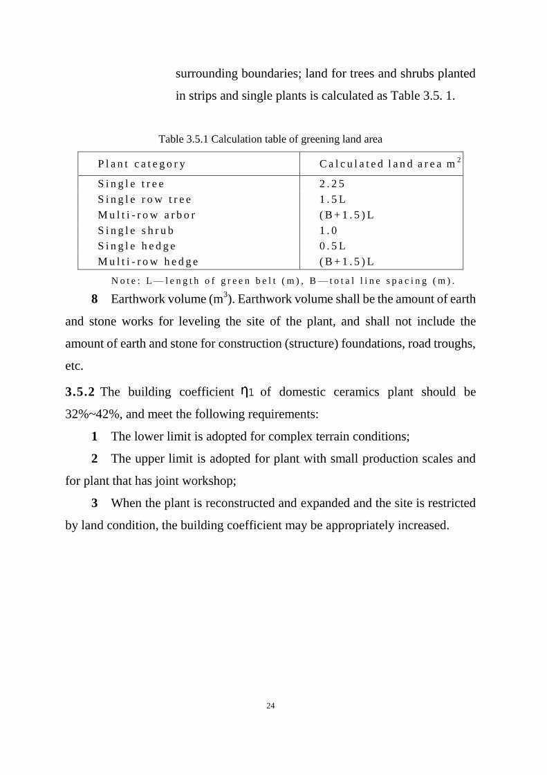
surrounding boundaries; land for trees and shrubs planted
in strips and single plants is calculated as Table 3.5. 1.
Table 3.5.1 Calculation table of greening land area
P l a n t c a t e g o r y C a l c u l a t e d l a n d a r e a m2
S i n g l e t r e e 2 . 2 5
S i n g l e r o w t r e e 1 . 5 L
M u l t i - r o w a r b o r ( B + 1 . 5 ) L
S i n g l e s h r u b 1 . 0
S i n g l e h e d g e 0 . 5 L
M u l t i - r o w h e d g e ( B + 1 . 5 ) L
N o t e : L — l e n g t h o f g r e e n b e l t ( m ) , B — t o t a l l i n e s p a c i n g ( m ) .
8 Earthwork volume (m3). Earthwork volume shall be the amount of earth
and stone works for leveling the site of the plant, and shall not include the
amount of earth and stone for construction (structure) foundations, road troughs,
etc.
3.5.2 The building coefficient of domestic ceramics plant should be
32%~42%, and meet the following requirements:
1 The lower limit is adopted for complex terrain conditions;
2 The upper limit is adopted for plant with small production scales and
for plant that has joint workshop;
3 When the plant is reconstructed and expanded and the site is restricted
by land condition, the building coefficient may be appropriately increased.
25
4 Pro c e ss
4.1 General provisions
4.1.1 Process design must conform with requirements of approved documents.
Advanced manufacturing method and process shall be used based on confirmed
production capacity, type of raw material and fuel, characteristic of ceramic type
and type of product, and sure the related technical parameters and economic
indexes shall reach the advanced level domestically.
4.1.2 The selection of equipment shall be met the requirement of pracicability,
safety, environmental, lower power consumption and higher efficiency.
Homemade equipments should be used and foregien advanced equipments may
be considered if necessary.
Besides, the standardization, serialization, mechanization and automation,
as well as unity and interchangeability shall be considered.
The equipment in the production plant shall meet the production capacity
requirements. For projects with annual production scale as the target, the
capacity of key equipment shall be considered based on the effective production
time of not less than 7,200 hours per year, and 10% surplus capacity should be
considered for other equipment.
4.1.3 The process design shall be combined with the requirements of general
plot plan and layout. The process flow shall be as short as possible under the
ensuring quality. The equipment and pipeline arrangement shall be easible for
facilitate construction, installation, operation, maintenance and repairment.
Production facilities with close production connections and/or similar
properties should form a combining factory building or multi-storey factory

26
building under the conditions of technological production, fire protection,
safety, nature lighting, and ventilation.
4.1.4 Environmental protection shall be emphasized during process designing,
with carring out the principal of “Prevention First, Prevention with Control,
Comprehensive Treatment” and “Three simultaneity”. Effective measures shall
be taken to reduce the emission of harmful material and noise, with perfect
occupational health facilities and measurements regarding safety and health.
4.2 Raw material workshop
4.2.1 The production methods and select equipment must be formulated based
on production capacity, ceramic type and characteristics of raw material during
process design of the raw material workshop.
4.2.2 The process design of the raw materials workshop shall meet the
following regulations and requirements:
1 The selection of raw materials shall meet the requirements of industry
standards, and must consider the service life and quality fluctuationof mining
source, physical characteristics of raw material, transportation condition and
method, and other related factors.
2 The crudes of kaolin and clay shall be inspected and selected to remove
the impurities in the mine site before transported to the raw material workshop.
3 The storage time of raw materials shall consider the affect of various
factors such as the type of raw materials, transportation methods, once feed
volume, transportation distance, number of retransmissions, maximum days of
suspension, fluctuations of raw materials composition, as well as market
conditions, capital turnover and price factors.
4 , The different raw materials shall be stored separately in the raw
material warehouse and be not mixing stored.

27
5 The aging time of preform body shall be shorted with permitted
processing performanc of preform body, should be 2~4days.
6 Raw material shall be transported to workshop after weighting and dry
basis conversion shallbe done after moisture content is measured.
7 Weighting and moisture content measurement shall be done when clay
slip, glaze slip and dry powder are transported out of workshop.
4.2.3 Process design parameters of raw materials workshop may may refer to
Table 4.2.3.
Table4.2.3 Main process design parameters of raw material workshop
I n d e x u n i t V a l u e
Loss of transportation, storage and pulping of raw
material
Kaolin, clay
Ore powder
Chemical raw materials
%
%
%
<4
<3
<1
Consumption of body materials
Porcelain weight: dry weight
1:1.6~1:1.8
Glaze consumption
Porcelain weight:dry material weight
1:7~1:9.5
Ball milling time (determined according to
experiment or actual production)
Body materials
Glaze
h
h
12~20
36~60
Filter press time m i n 40~60
Spray drying energy consumption kJ/kgH2O <3100
4.2.4 The main equipment selection of the raw materials workshop shall meet
the following regulations and requirements:
1 Equipment with the same function should select the same model and
specification.
2 Equipments made of stainless material shall be selected.
3 Specification and amount of ball mill shall be determined based on
process demand and loading capacity of single equipment, with consideration of

28
time of loading and discharging, time of replacing ball and lining and time of
maintenance.
4 Spare feeding equipment and feeding lifting equipment of ball mill
should be considered.
5 Plunger slip pump or variable flow plunger slip pump should be used
for transport slip to filter press.
6 Three-shaft stainless steel de-airing pug mill should be selected to
pugging.
7 Necessary lifting facilities should be configured in raw materials
workshop accordineg to the configuration of production equipment.
4.2.5 The process layout of the raw materials workshop shall meet the
following regulations and requirements:
1 The process arrangement should follow the following principles:
1) It is advisable to use the self-weight of the material to realize the
gravity flow between processes. The equipment connecting to each other should
be arranged as close as possible, and the lines should be smooth and short to
reduce the quantity of conveying equipment and the resistance of pipelines;
2) Passage way of people and logistics should be arranged
coordinatively in the plant to avoid cross and mixing;
3) Equipment shall be arranged to allow workers easy access to
operation and maintenance, with considering location of power distribution and
dust removal facilities in the plant.
2 The net distance between equipment and equipment, column or wall
shall comply with the requirement showed in Table 4.2.5, and the influence
between equipment foundation and pit, trench, foundation of wall or column
shall be considered.
Table 4.2.5 Net distance of equipment
Name unit Operation side Non-operat
ing side Trolley access Forklift access

29
Net distance between equipment m 1.5~3.0 0.8~1.2 1.5~2.0 2.5~3.0
Net distance between equipment.
column or wall m 1.5~2.0 0.8~1.0 1.5~2.0 2.5~3.0
3 The reserve space for the ball mill and slip tank shall be considered
according to any factors such as process requirements, site size, and expansion
needs.
4 The storey height of the factory building shall considered with the
space need of equipment installation and maintenance.
5 The raw materials workshop should be equipped with auxiliary rooms
such as small inspection room, duty room, spare parts room and tool room.
4.3 Forming workshop
4.3.1 The production method and process flow must be considered based on
production capacity, products scheme, quality requirement and process
characteristics of body materials and glaze during the process design of forming
workshop.
4.3.2 The process design shall meet the following requirements:
1 Storage time of pugged mud body should not be more than 4 hours.
2 Stainless material shall be used as slip pipe material when producing
fine porcelain.
3 Air pipe of the dryer used to produce fine porcelain should be anti-rust
treated. Stainless plate is suggestedto used.
4 The semi-finished product should be stored in a storage container or
stored on the kiln car directly, and be not stored with too long time.
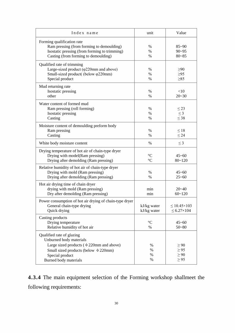
4.3.3 Process design parameters of forming workshop may may refer to Table
4.3.3.
Table 4.3.3 Main process design indicators of Forming workshop
30
I n d e x n a m e unit Value
Forming qualification rate
Ram pressing (from forming to demoulding)
Isostatic pressing (from forming to trimming)
Casting (from forming to demoulding)
%
%
%
85~90
90~95
80~85
Qualified rate of trimming
Large-sized product (φ220mm and above)
Small-sized product( (below φ220mm)
Special product
%
%
%
≥90
≥95
≥85
Mud returning rate
Isostatic pressing
other
%
%
<10
20~30
Water content of formed mud
Ram pressing (roll forming)
Isostatic pressing
Casting
%
%
%
≤ 23
≤ 3
≤ 38
Moisture content of demoulding preform body
Ram pressing
Casting
%
%
≤ 18
≤ 24
White body moisture content % ≤ 3
Drying temperature of hot air of chain-type dryer
Drying with model(Ram pressing)
Drying after demolding (Ram pressing)
°C
°C
45~60
80~120
Relative humidity of hot air of chain-type dryer
Drying with mold (Ram pressing)
Drying after demolding (Ram pressing)
%
%
45~60
25~60
Hot air drying time of chain dryer
drying with mold (Ram pressing)
Dry after demolding (Ram pressing)
min
min
20~40
60~120
Power consumption of hot air drying of chain-type dryer
General chain-type drying
Quick drying
kJ/kg water
kJ/kg water
≤ 10.45×10³
≤ 6.27×10⁴
Casting products
Drying temperature
Relative humidity of hot air
°C
%
45~60
50~80
Qualified rate of glazing
Unburned body materials
Large sized products (φ220mm and above)
Small sized products (below φ220mm)
Special product
Burned body materials
%
%
%
%
≥ 90
≥ 95
≥ 90
≥ 95
4.3.4 The main equipment selection of the Forming workshop shallmeet the
following requirements:

31
1 The level of mechanization and automation of the equipment and the
adaptability to different products shall be considered according to factors such as
the shape, specification, and processing technology of the product.
2 Disc products and shallow bowl products should be formed by a convex
mold roll forming machine or an isostaticpressing machine.
3 Deep bowl products should be formed by a concave mold roll forming
machine or an isostaticpressure forming machine.
4 The fish dishes should be formed by press casting machine, ram
pressing machine, or isostaticpressing machine.
5 For domestic ceramic products with complex structures, three
dimension printing technology may be used.
6 The casting material should be processed by a vacuum defoaming
mixer, and special shaped hollow products should be formed by a centrifugal
slip casting machine.
7 Body materials should be dried by high-efficient and energy-saving
chain-type dryer or other advanced drying equipment. Except for large or
special-shaped products, chamber drying rooms are not suitable.
8 Drying process test should be done before using a rapid dryer.
9 Waste heat of kiln shall be utilized fully as heat source of drying
preform body. When the waste heat is insufficient, gas fuel or steam may be used
as a supplementary heat source, and the heat source from direct coal burning is
not allowed.
4.3.5 The equipment layout of the Forming workshop shall meet the following
requirements:
1 Linear layout should be maded according to type. Process flow shall be
reasonable and compact, piping should be short to avoid cross or material
returning transportation.
32
2 When arranging the equipment, in addition to meeting the operation
and maintenance requirements of the equipment itself and its auxiliary devices,
the clear width of the front passage of the forming machine shall not be less than
3m, the clear width of other main passages shall not be less than 2m, and the net
distance between equipment or forming lines shallnot be less than 1.5m.
3 The location of the equipment starting device shall be convenient for
the operator to observe the equipment run and surrounding conditions, and the
accident stop button shall be set near the equipment.
4 Multi-storey factory buildings without freight elevators shall be set
lifting holes, and the size of the holes shall be 0.3~0.5m larger than the outer
dimensions of the equipment or the largest lifting component.
5 For the Forming workshop without permanent lifting facilities, there
shall be enough space and site for erecting temporary lifting devices, and the net
space should not be less than the height of the equipment plus 2 meters.
6 When arranging equipment, the location of the stairs, workshop power
distribution, ventilation and dust removal facilities shall be considered, and the
influence between the equipment foundation and pit, trench, and foundation of
wall and column shall be considered.
7 The Forming workshop should be equipped with auxiliary facilities and
rooms such as spare parts room and tool room according to the production scale,
the quantity and complexity of the equipment.
4.4 Firing workshop
4.4.1 The suitable furnance and producing process shall be decided based on
production capacity, products scheme and quality requirement for Firing
workshop.
4.4.2 The process design of the Firing workshop shall meet the following
requirements:

33
1 The firing process shall be decided to be single firing or double firing
according to raw material formula, porcelain quality requirements, fuel type and
supply condition. The energy-saving technology called low-tempeture fast
single firing is preferred. Double firing is suitable to produce high-grade fine
porcelain.
2 The specifications and quantity of firing kilns shall be determined
according to the production capacity and the balance of capacity of each
equipment in the whole plant, and factors such as comprehensive qualification
rate, the loss of semi-finished products during inspection and selection and
transportation shall be considered.
3 Fuel type shall be decided after analyzing technically and economically
based on national energy policy and local fuel supply condition. Clean fuel is
preferred.
4 When using clean fuel gas, naked burning firing technology shall be
used.
5 The firing schedule shall be determined according to the result of
semi-industrial test useing the raw materials. If there is sufficient mature
experience, it may be determined according to the firing schedule of similar
products and kilns.
4.4.3 The main process design indexes may be refered according to the
following data:
1 Moisture content of the preform body into the kiln: ≤ 3%
2 Comprehensive qualification rate of firing: Biscuit firing: ≥ 95%
Glaze firing: ≥ 95%
3 White porcelain inspection damage ratio: <1%
4.4.4 The main equipment selection of the Firing workshop shall meet the
following requirements:
34
1 Tunnel kiln or roller kiln which is easy to change firing schedule and
lower energy consumption shall be selected.
2 Kiln furniture made by cordierite, mullite cordierite, silicon carbide,
fused quartz or new manufacture technology may be used according to different
firing temperature and product classification.
3 The number of kiln cars for tunnel kiln shall be determined based on
factors such as the car number of parking in the kiln, the occupation car number
under loading and unloading, the car numberstopping on the return track, the car
numberwith load, the occupation car number of ready to unload and the number
of kiln cars in maintenance.
4.4.5 The equipment layout of the Firing workshop shall meet the following
requirements:
1 The equipment layout of the Firing workshop shall meet the needs of
production operation, transportation, and hot repair and cold repair for kiln. The
net width of the passage between the equipment shall not be less than 0.6m, and
the net space between the equipment and the building walls and columns shall
not be less than 0.8m.
2 The layout of the workshop shall make the transportation of
semi-finished products, finished products and kiln furniture smooth and
convenient. Any storage area shall be considered.
3 The outside of tunnel kiln shall be set with loading and unloading lanes,
return lanes, storage lanes, and inspection lanes. The quantity and length of each
kind of lane shall be determined according to the number of tunnel kilns, product
types, and work time of loading and unloading of kiln cars.
4.4.6 The Firing workshop shall be set the control room with thermal
instrument separately .
4.5 Decorating Firing workshop
35
4.5.1 The producing method and the selection of equipment shall be
determined based on color porcelain proportion and color-decoration
requirements during the process design of decorating firing workshop.
4.5.2 The process design of the decorating firing workshop shall meet the
following requirements:
1 Material such as decals, liquid gold and coloring agent for color-
decoration shall be stored in a separate room and kept by dedicated persons. The
temperature in the storage room should be kept at 18~25℃. Generally, the
storage time of liquid gold does not exceed 18 months, and that of decal dose not
exceed 6 months .
2 White porcelain shall be cleaned before decorated.
3 During returning between color-decoration and decorating firing, the
storage capacity of each section should be determined with the site conditions.
Product shall be stored in specified plastic or wood container, and enough space
shall be considered for storaging containers.
4 Added decorating firing times shall be included in decorating firing
producing capacity if there is multi-firing demand for product color.
5 Energy-saving technology of low-temperature decorating firing shall
be applied.
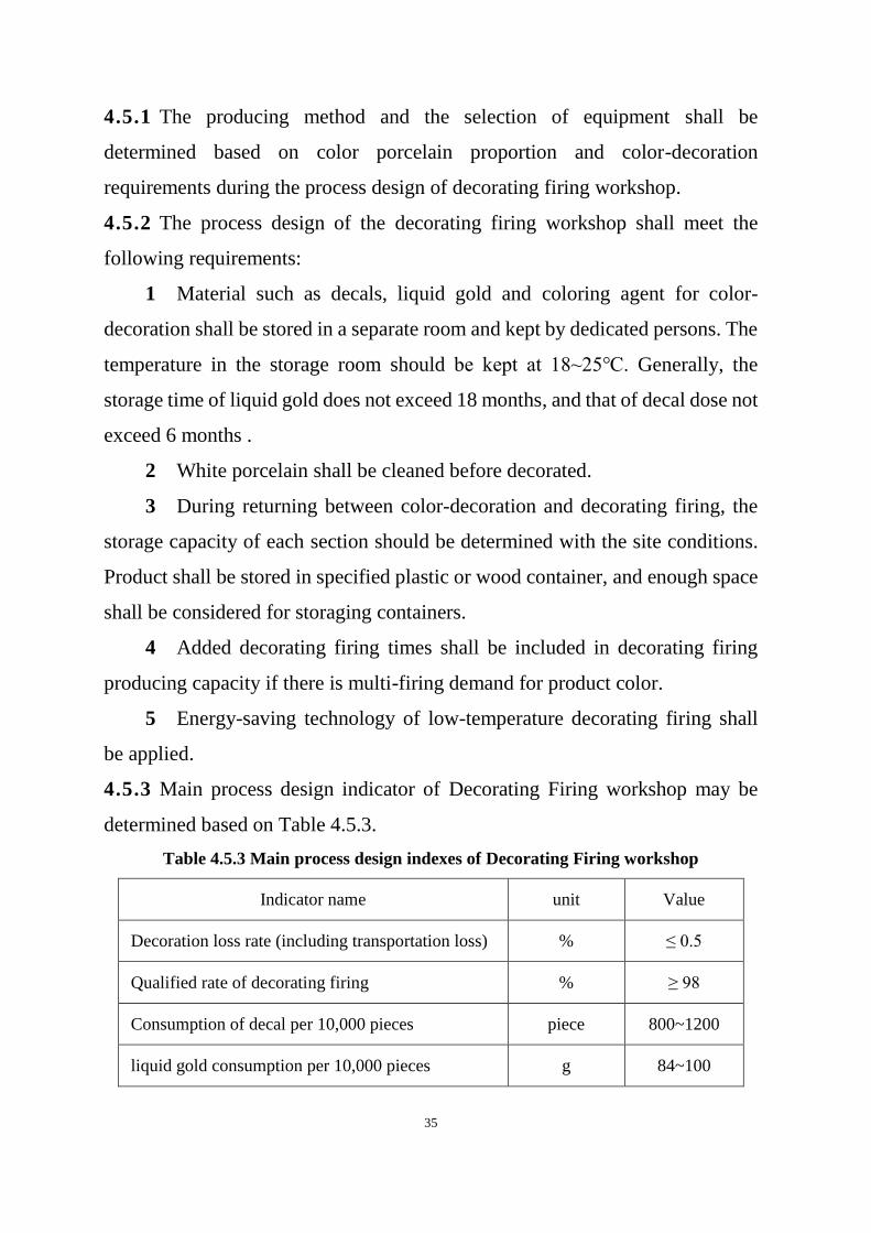
4.5.3 Main process design indicator of Decorating Firing workshop may be
determined based on Table 4.5.3.
Table 4.5.3 Main process design indexes of Decorating Firing workshop
Indicator name unit Value
Decoration loss rate (including transportation loss) % ≤ 0.5
Qualified rate of decorating firing % ≥ 98
Consumption of decal per 10,000 pieces piece 800~1200
liquid gold consumption per 10,000 pieces g 84~100
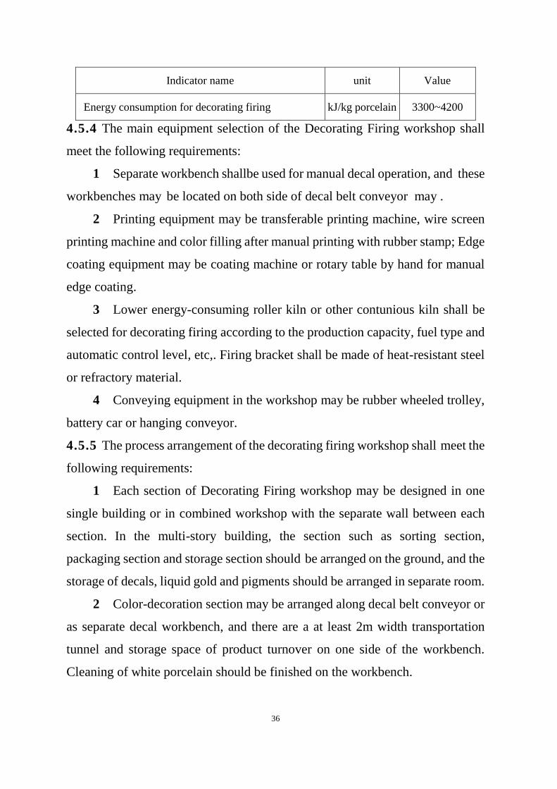
36
Indicator name unit Value
Energy consumption for decorating firing kJ/kg porcelain 3300~4200
4.5.4 The main equipment selection of the Decorating Firing workshop shall
meet the following requirements:
1 Separate workbench shallbe used for manual decal operation, and these
workbenches may be located on both side of decal belt conveyor may .
2 Printing equipment may be transferable printing machine, wire screen
printing machine and color filling after manual printing with rubber stamp; Edge
coating equipment may be coating machine or rotary table by hand for manual
edge coating.
3 Lower energy-consuming roller kiln or other contunious kiln shall be
selected for decorating firing according to the production capacity, fuel type and
automatic control level, etc,. Firing bracket shall be made of heat-resistant steel
or refractory material.
4 Conveying equipment in the workshop may be rubber wheeled trolley,
battery car or hanging conveyor.
4.5.5 The process arrangement of the decorating firing workshop shall meet the
following requirements:
1 Each section of Decorating Firing workshop may be designed in one
single building or in combined workshop with the separate wall between each
section. In the multi-story building, the section such as sorting section,
packaging section and storage section should be arranged on the ground, and the
storage of decals, liquid gold and pigments should be arranged in separate room.
2 Color-decoration section may be arranged along decal belt conveyor or
as separate decal workbench, and there are a at least 2m width transportation
tunnel and storage space of product turnover on one side of the workbench.
Cleaning of white porcelain should be finished on the workbench.

37
3 Decorating firing section may be arranged based on type and quantity
of kiln, and the storage space for product turnover near loading & unloading
operation zone. Kilns should be arranged on the same side if there are two or
more kilns. High-pressure fans of kiln should be arranged in separate room, the
pipe of exhausting air and fuel gas should extend to the outside of the room.
4 The reparation location of color porcelain defects should be arranged
in the decorating firing workshop for premium fine porcelain production.
4.6 Plaster moulding workshop
4.6.1 The process design of the Plaster moulding workshop shall meet the
following requirements:
1 The gypsum powder used for the plaster moulding shall meet the
quality requirements of the industry standard.
2 When gypsum slip is prepared, a vacuum deaeration mixer shall be
used for vacuum deaeration and stirring of gypsum slip.
3 Drying of gypsum model should adopt a chamber type drying room.
4 The plaster moulding workshop should be arranged close to the
Forming workshop. When they are arranged in the same building, the model
preparation section and forming section shall be separated by walls.
5 The plaster moulding workshop shall be equipped the storage site of the
model and gypsum powder for the model mold and master mold. The place for
storing gypsum powder shall be moisture proof and wet proof.
4.6.2 Main process design parameters of plaster moulding workshop may be
refer to Table 4.6.2.
Table 4.6.2 Main process design indicators of Plaster moulding workshop
Index name unit Value
Gypsum powder loss rate % 5~10
Damage rate of plaster model % 3~5

38
Gypsum slip stirring time min 3~4
Hot air temperature of model drying °C 50~60
Hot air relative humidity of model
drying % 50~80
Model drying time (chamber drying) h 12~20
Model drying final moisture content % 3~6
Model service life
Roll forming
Casting
Times
Times
≥ 60
≥ 50
4.7 Packaging warehouse
4.7.1 Domestic ceramic products shall be inspected, sorted and graded brfore
package.
4.7.2 The production line for inspection and sorting and grading should be
arranged near package line. Color ceramic products shall be separately stored
according to their grade, cup-shape products should be stored in plastic boxes or
wood boxes, and the stack height is not higher than 1.8m; dish-shape products
should be stored in layer,and the stack height is not higher than 1.2m.
4.7.3 Domestic ceramic products should be packed in cartons. Plate-shape,
dish-shape, and bowl-shape ceramic products should beseparated each other
cardpaper before package. Cup-shape products shall be separated each other
with flexible sanitary materials before package.
4.7.4 Domestic ceramic products may be stacked and stored in different areas
of warehouse according to product type and product grade.
4.7.5 Domestic ceramic products may be stored on multi-storey rack in
high-bay warehouse. The design of automated storage and retrieval system may
be carried out in accordance with the relevant provisions of Automated storage
and Retrieval System-General Rules (JB/T 10822), Automated storage and
39
retrieval system --- Design rules (JB/T 9018) and Design specification for
automated high-bay warehouse in petrochemical industry (SH/T 3186).
4.7.6 Multi-storey racks may be implemented in accordance with the
requirements of High bay welded steel rack ---- Specicfications (JB/T 5323).
4.7.7 The channel coefficient of the finish product warehouse should be
0.6~0.7.
4.7.8 The finish product warehouse should be equipped with transportation and
hoisting equipment for storage and external transportation.
4.7.9 The design of packaging material warehouse shall meet the required
storage area. The warehouse shall be covered with shed to prevent exposure to
the sunshine, rain or humidity. The cartons for inner and outer package or other
packaging materials stored in the warehouse shall be stored in piles, and the
stacking height should be 2.5 ~ 3.0m.
4.8 Process piping
4.8.1 The design of process pipe shall comply with Design code for Industrial
Metallic Piping (GB 50316), Pressure piping code ---- Industrial piping (GB/T
20801), Pressure Pipe Safety Technology Supervision Regulation for Idustrial
Pressure Pipe (TSG D0001) and other related standards.
4.8.2 The design of process pipe direction and location arrangement shall meet
the requirements of process flow, and make the short pipe line, less fittings, safe
and convenient operation and maintenance.
4.8.3 The selection of material of pipe, fitting and accessories shall be
determined based on operation condition, medium characteristic, load
distribution and other factors.
The materials of pipes and valves for the common medium in domestic
ceramic plants may be selected refering to Table 4.8.3.
Table 4.8.3 Material selection table for pipes and valves

40
Type of medium Pipe material Valve material
Body Core/ Gate
Glaze slip Stainless steel pipe, copper pipe,
engineering plastic pipe
stainless steel
Engineering
plastics
Stainless steel, copper
clay slipClay
slip
Stainless steel pipe, copper pipe,
engineering plastic pipe
Stainless steel,
carbon steel
Engineering
plastics
Stainless steel, copper
fuel Stainless steel pipe, steel pipe, PE
pipe for gas
Stainless steel,
carbon steel
Copper, titanium,
PE plastic
Stainless steel, carbon
steel
Copper, titanium, PE
plastic Metal valves for fuel gas shall meet the requirements in Metal Valves for
Gas Transmission (CJ/T 514).
4.8.4 The specification and connection type of pipe
1 The pipe specifications should be selected the preferred outside
diameter size series in the relevant standards, and the pipe fittings shall also be
selected the same outside diameter size series as pipe according to the standard
requirements.
2 The inside diameter of the pipeline shall be determined by calculation
based on factors such as the flow rate of the conveying medium, economic flow
rate, and maximum allowable pressure drop. The wall thickness of the pipeline
shall be determined based on the pressure, temperature, stiffness and flexibility
of the pipeline, and the influence of corrosion shall be considered, etc..
The flow velocity in the common medium pipes of domestic ceramic plant
may are refer to Table 4.8.4.
Table 4.8.4 Flow rate range table for different medium pipes
Medium Name Velocity range (m/s)
Glaze slip 0.5~0.8
Clay slip 0.5~1.2
3 The connection type of the pipe shall be determined by the operating
conditions of the conveying medium and the characteristics of the medium under

41
such operation condition. The connection type such as welding, threaded
connection, flange connection, union connection may be used.
4.8.5 The fuel delivery pipeline design shall meet the following requirements:
1 The design of the fuel pipeline shall meet the requirements in Code for
design and construction of filling station (GB 50156), Code for design of
liquefied petroleum gas ( LPG) supply engineering (GB 51142), Design code for
producer gas station (GB 50195), Code for design of city gas engineering
(GB50028) and Technical standard for polyethylene (PE) gaseous fuel pipeline
engineering (CJJ 63).
2 Steam heat tracing should be adopted along the heavy oil for fuel
pipeline, and pipeline cleaningdevices in steam shall be installed. Measures shall
be taken to prevent oil entering the steam pipe at the joint of the oil and steam
pipes.
3 The fuel pipeline shall be equipped with a reliable electrostatic
grounding device.
4.8.6 Pipeline layout
1 Pipe in the workshop should be laid overhead along the wall or column,
or underground if necessary. When laid underground, pipe trench shall be set,
and the elevation of trench cover top shall be the same as that of ground surface.
2 Outdoor pipelines should be laid overhead.
3 The net space of indoor pipe crossing pedestrian passage shall not be
less than 2.2m. The space of the pipe crossing the passage of transportation
equipment in the workshop shall meet requirements of equipment transportation.
4 The net space of outdoor pipe crossing the road shall not be less than
4.6m. Anti-freezing measures shall be taken for outdoor pipe in cold region.
5 There should be no welding seam, valve and other pipe accessories in
the pipeline above the equipment, motor or electrical switch cabinet, otherwise
the reliable protection measures should be taken for this electrical facilities.

42
6 The casing pipe shall be embedded for pipe crossing wall and floor.
There shall be no welding seam in the pipe section inside the casing pipe, and the
gap between the pipe and the casing and the filling material in gap shall meet the
requirements of anti-shock and anti-fire.
7 Valve arrangement shall meet the requirements of valve structure and
medium characteristics. Valve shall be arranged on location easy operation and
maintenance, and shall not hinder the disassembly and repair of higher
equipment body and pipe.
8 The layout of indoor pipe trench shall be considered in combination
with other trenches in the plant. The direction of pipe trench shall meet the needs
of production process, reducing the crossing of trenches and avoiding laying the
trench under the main passage way.
9 The pipe layout shall sure the distance between pipes and between pipe
and beam, columns and wall to meet the needs of installation, operation and
maintenance. The size of pipe spacing may refer to the relevant codes and
standards.
10 The pipe shall be designed with certain pipe slope. The slope may be
determined as following except there is special requirement:
1) Gravity flow pipe shall be slpoed along the flow direction of the
medium, and the slope of glaze slip pipeline and clay slip pipeline shall not be
less than 2%;
2) Forced flow pipe: The slope along the flow direction of glaze slip
pipeline, Clay slip pipeline and fuel oil pipeline shall not be less than 0.5% ~1%,
and the slope of fuel gas pipeline shall not be less than 0.2%.
4.8.7 Anti-corrosion, thermal insulation and coloring of pipe shall meet
requirements as following:
1 Carbon steel pipelines engineering shall comply with Design code for
external corrosion protection of chemical equipment and piping (HG/T 20679),
43
Design specification for anticorrossion coating of equipment and piping in
petrochemical engineering (SH/T 3022) and Code for construction and
acceptance of chemical equipment and pipeline anticorrosive engineering (HG
/T 20229) and other relevant standards.
2 The thermal insulation design of the pipeline shall be implemented in
accordance with the Code for design of industrial equipment and pipeline
insulation engineering GB 50264.
3 For the pipelines at the reachable location by person that do not require
thermal insulation in the process, the corresponding protective measures shall be
adopted to avoid person touching according to the temperature of the medium
transported by the pipeline.
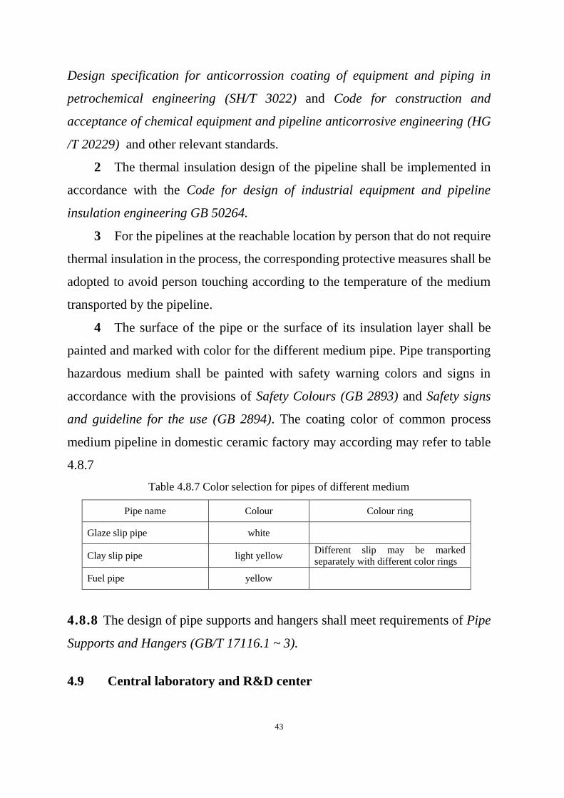
4 The surface of the pipe or the surface of its insulation layer shall be
painted and marked with color for the different medium pipe. Pipe transporting
hazardous medium shall be painted with safety warning colors and signs in
accordance with the provisions of Safety Colours (GB 2893) and Safety signs
and guideline for the use (GB 2894). The coating color of common process
medium pipeline in domestic ceramic factory may according may refer to table
4.8.7
Table 4.8.7 Color selection for pipes of different medium
Pipe name Colour Colour ring
Glaze slip pipe white
Clay slip pipe light yellow Different slip may be marked
separately with different color rings
Fuel pipe yellow
4.8.8 The design of pipe supports and hangers shall meet requirements of Pipe
Supports and Hangers (GB/T 17116.1 ~ 3).
4.9 Central laboratory and R&D center

44
4.9.1 The central laboratory of the domestic ceramic plant shall meet the
following requirements:
1 Analyze and monitor the quality of raw materials, muds, glazes,
semi-finished products and finished products;
2 Analyze the factors affecting quality and provide inspection services
for each process in production;
3 Provide technical guidance for inspections in various workshops, unify
inspection methods, and calibrate equipment.
4.9.2 The central laboratory may include these function of chemical analysis,
physical testing, lead and cadmium release testing, thermal testing, sample
processing, instrument and drug storage, and file management.
4.9.3 The equipment configuration of the central laboratory should follow the
following principles:
1 The instrument and equipment configuration of the central laboratory
may be determined according to the production capacity, products
characteristics and local cooperation conditions.
2 The main equipment for chemical analysis shall be able to meet the
requirements of conventional chemical composition analysis, rapid analysis of
potassium and sodium composition, and analysis of lead and cadmium release
from finished products.
3 The main physical testing equipment shall be able to meet the
requirements of raw materials, mud and glaze performance test, sintering
performance test, product performance test, and gypsum performance test.
4 General instruments and equipment should be planned and set up
centrally.
4.9.4 A research and development center should be set up in domestic ceramic
factory. The R&D center may be set up separately or combined with the central
laboratory.

45
4.9.5 The equipment configuration in the R&D center shall be able to meet the
needs of new product trial production research. Small equipment such as blank
glaze preparation, forming, firing, mold making and pigment preparation should
be equipped.
46
5 Ki l n
5.1 General provisions
5.1.1 The fuel used in the kilns of domestic ceramic plants shall be selected in
accordance with the national energy policy and the principles of local conditions
and local materials, combined with consideration of fuel cost, energy saving,
convenient operation and environmental protection regulations.
5.1.2 Newly built or rebuilt kilns shall use clean gas as fuel. For the domestic
ceramics plants that are expanded or renovated, the kilns that directly burn coal
should be converted to clean gas as fuel.
5.1.3 In addition to clean gas, electric energy may be used for newly built or
rebuilt kilns.
5.1.4 Kiln design must follow the principle of energy saving in terms of kiln
type selection, structural design, material selection and waste heat utilization.
5.2 Kiln type selection
5.2.1 For new, rebuilt and expanded domestic ceramic factories, the kiln type
shall be determined based on product type, scale and fuel.nded domestic ceramic
factories, the kiln type shall be determined based on product type, scale and fuel.
5.2.2 Shuttle kilns using clean gas as fuel may be used for the firing of small
batch products or special products or test products.
5.2.3 Roller kiln or push plate kiln may be used for product with body glaze
suiting rapid firing
5.3 Determination of main technical and ecomic index
5.3.1 The firing qualification rate of the kiln shall be calculated as follows:
𝜂 ≥ 𝜂0 +(1 − 𝜂0) ( 5 . 3 . 1 - 1 )

47
Herein: 𝜂 —— Kiln firing qualification rate,%
𝜂0 —— Local regulated minimum firing qualification rate
5.3.2 Unit energy consumption (kJ / kg) of kiln-fired products shall include the
energy consumption of single firing and double firing product, and shall be
calculated the weight of product that enter into the kiln, which shall meet the
requirements as following:
1 The energy consumption per unit product of domestic ceramic of new
or rebuilt or expanded domestic ceramic production lines shall not be higher
than the requirements of energy consumption limit level 2 specified in The norm
of energy consumption per unit products of domestic ceramics (GB 36890).
2 Fuel consumed during the kiln drying and commissioning is excluded
in the calculation of energy consumption per unit fired products.
5.3.3 Thermal efficiency of fired product in the kiln shall not be less than 40%.
The calculation of thermal efficiency may be conducted based on Measurement
and calculation method of heat balance and thermal efficiency (GB/T 23459).
48
6 F u e l
6.1 General provisions
6.1.1 Domestic ceramic plants may use natural gas, liquefied petroleum gas,
town fuel gas, producer gas, fuel oil and other clean fuels. The selection of fuel
shall comply with process requirements, with focusing on proper usage of
energy-saving and environment-friendly clean fuel.
6.1.2 The design of gas station, oil depot and their pipeline shall comply with
the provision of this chapter as well as current national and industrial standards,
codes and regulations
6.1.3 Environmental protection and safety protection facilities of gas station,
liquefied petroleum gas gasification station and oil depot must be designed at the
same time with the main project, and shall comply with the provisions of
relevant national or local standards and specifications, and meet the control
requirements of harmful substance and noise emission.
6.2 Fuel Gas
6.2.1 Natural gas used for kiln fuel gas shall meet the requirements of Natural
Gas (GB 17820) and meet the following requirements:
1 Natural gas shall have a standby gas supply source, or there is other
backup fuel.
2 The hydrogen sulfide content in natural gas shall be less than
20mg/Nm3.
6.2.2 Liquefied petroleum gas used for kiln fuel gas shall comply with the
regulations of Liquefied Petroleum Gas GB 11174.
6.2.3 Coal gas used for kiln fuel gas shall meet the following requirements:
1 Coal gas shall be supplied continuously with stable flow and pressure.

49
2 The low calorific value of coal gas shall not be lower than
5.0×10³kJ/m
3.
3 The coal gas shall be clear, and the content of dust and tar in coal gas
shall be controlled.
4 The content of hydrogen sulfide in coal gas shall meet the requirements
of product quality and environmental protection.
6.2.4 The design of the gas distribution station and the pressure regulating
room shall meet the regulations and requirements of the Code for design of city
gas (GB50028).
6.2.5 The fire protection design of the pressure regulating room shall meet the
regulations and requirements in the Code of Design on Building Fire Protection
and Prevention (GB 50016).
6.2.6 The storage, transportation and usage of LNG or CNG shall comply with
provision of Code for design and construction of filling station (GB 50156).
6.2.7 The storage, transportation and use of liquefied petroleum gas shall
comply with the Code for design of liquefied petroleum gas ( LPG) supply
enginering (GB51142).
6.2.8 The design of producer gas station shall meet the requirements of Design
code for producer gas station (GB 50195).
6.3 Fuel oil
6.3.1 Fuel oil system shall meet requirements as following:
1 Oil shall be supplied continuously with stable pressure and flow.
2 The oil viscosity meets the atomization requirements of burner.
3 The impurity content in the oil is few.
6.3.2 The loading, unloading, storage, transportation and use of fuel oil shall
meet the requirements of Code for Design and Construction of Automobile
50
Filling Station (GB 50156). Heating and thermal insolution system shall be
considered for storage of heavy oil.
6.3.3 The fuel oil supply design of the workshop shall meet the following
requirements:
1 When the oil tank farm is far away from the workshop user, the
intermediate storage tank should be set, and the oil storage capacity should be
met the oil consumption for 1 ~ 2 days of workshop.
2 The kiln oil supply system shall ensure the stability of the fuel oil
temperature, oil pressure and viscosity.

51
7 Th e r ma l pow e r
7.0.1 It is based on national energy saving policy and technical & economic
analysis according to the local central heating condition or plan whether
domestic ceramic plant needs to build industrial boiler or not.
7.0.2 Heating design shall comply with current national standards,
regulations and principals.
7.0.3 The design of boiler room is based on production process and heat
loading curve provided by heating & ventilation descipline. The arrangement
of boiler shall meet requirements of loading change and spare boiler shall be
arranged based on technical & economic analysis.
7.0.4 Heating supply should be designed based on possible expansion and
related requirements.
7.0.5 Maintenance and laboratory room and equipment required for heating
facilities should be considered in general plan of plant. The design of heating
supply shall be considered with operation maintenance and supervison
facilities.
7.0.6 The expansion or rebuilding design of heating design facilities shall be
based on energy-save premise, with focusing on the potential of original
equipment. Its main technical and economic indexes shall be better than those
before expansion and reconstruction.
7.0.7 For a single boiler with a capacity of less than 10t/h, the feedwater
deaeration should adopt low-level water jet vacuum deaeration or a new type
of desorption deaeration device.
7.0.8 The design capacity of the chemical water treatment in the boiler room
should include the consumption of softened water required by the
self-provided gas station and other departments.
52
7.0.9 The hydrophobic heat shall be recycled and the recovery rate shall be
greater than 60%. The make-up water from production steam, heating
ventilation and air conditioning steam should be recycled, and the condensate
water return device may be set separately or shared with the drain tank of
heating facilities.
7.0.10 The boiler room shall be equipped with necessary instruments for
monitoring the safe operating parameters of the boiler unit, as well as
instruments for monitoring the economic operation and economic accounting
of the boiler unit.
7.0.11 The fans, water pumps and other equipment in the boiler room shall be
made of high-efficiency, energy-saving and low-noise products.

53
8 Pow e r S u pp ly
8.0.1 The electrical design of domestic ceramic plant shall meet needs of
process design, and should include power transformation and distribution,
worshop power, lighting, lighting protection, grounding and so on.
8.0.2 The electrical design shall meet producing requirements, and shall
satisfy the needs of recent development, convenient management, safe
maintenance, less investment, low energy consumption and easy economic
analysis.
8.0.3 Power load classification
1 Power load of Firing workshop, fuel gas station, oil pump station,
boiler station, fire water pump station, and waste water treatment station shall be
level 2.
2 Power load of raw material workshop, Forming workshop, Decorating
Firing workshop, Plaster moulding workshop, central labtoraty and R & D
centre, auxiliary workshop, office building, warehouse, vehicle warehouse,
factory lighting, life area and so on should be level 3.
3 Power source shall be determined based on local power supply
condition, and two signle power sources are preferred. When there is only one
electricity source, diesel generator set with proper capacity shall be equipped in
the plant as standby power supply for kiln, gas station, oil pump room, boiler
room, water pump room and fire fighting system.
8.0.4 Power load should be calculated by the demand coefficient method and
compared with power consumption per unit product. Calculated load demand
factor of main electrical equipment in main workshop may be determined
according to Table 8.0.4.

54
Table 8.0.4 Calculated load demand factor of main electrical equipment
8.0.5 The voltage of power supply shall be determined based on the size and
distribution of power loading in the plant, regional power supply conditions,
power supply distance and economic rationality. 10kV power supply is
preferred, and 35kV Power supply may be used for large projects
W o r k s h o p
n a m e E q u i p m e n t n a m e K c Cosφ
R a w
m a t e r i a l
w o r k s h o p
B a l l m i l l 0 . 7 5 0 . 8
V i b r a t i n g s c r e e n 0 . 5 0 . 6 5
H o i s t , b e l t c o n v e y o r ,
e l e c t r o m a g n e t i c i r o n
a b s o r b e r
0 . 6 0 . 7
C l a y s l i p p o o l m i x e r 0 . 6 0 . 8
C l a y s l i p p u m p s , a i r
c o m p r e s s o r s a n d p u m p s 0 . 7 0 . 8
F i l t e r p r e s s 0 . 6 0 . 7 5
V a c u u m m u d r e f i n e r 0 . 8 0 . 8
E l e c t r i c h o i s t 0 . 2 0 . 5
V e n t i l a t o r 0 . 6 5 — 0 . 7 0 . 8
F o r m i n g
w o r k s h o p
G l a z i n g m a c h i n e , f o r m i n g
m a c h i n e , c h a i n d r y e r 0 . 5 0 . 7
G r o u t i n g m a c h i n e 0 . 6 0 . 7
C h a i n c o n v e y o r 0 . 6 5 0 . 8
e l e v a t o r 0 . 3 0 . 6
F i r i n g
w o r k s h o p
E l e c t r i c p i g g y b a c k 0 . 4 0 . 6
P o l i s h i n g m a c h i n e ,
g r i n d i n g m a c h i n e , c a r
p u s h e r
0 . 5 0 . 7
V e n t i l a t o r 0 . 7 5 0 . 8 5
G a s s t a t i o n
P u m p s a n d f a n s 0 . 7 0 . 8
T r a n s p o r t a i r c r a f t w i t h
i n t e r l o c k 0 . 6 5 0 . 7 5
T r a n s p o r t w i t h o u t
i n t e r l o c k i n g 0 . 5 0 . 7 5

55
8.0.6 When the power supply voltage is 35kV, the secondary step-down
scheme or the 35 / 0.4kV primary step-down scheme shall be determined on
the basis of technical and economic comparison.
8.0.7 The maximum capacity of a single transformer should not exceed
2000kVA, and shall consider the short-circuit working conditions of
low-voltage electrical appliances and appropriate allowance.t.
8.0.8 In the low-voltage power network of TN system grounding type, the
three-phase transformer with D,ynll connection should be selected. On-load
tap changer may be used in factories with large grid voltage deviation and
failing to meet voltage quality requirements.
8.0.9 The selection of electrical equipment and wiring should be adapted to
the natural environment characteristics of the place of use. The main
environmental characteristics of each use place of the domestic ceramic plant
may be determined according to Table 8.0.9.

56
Table 8.0.9 Table of main environmental characteristics of special use places
W o r k s h o p n a m e A p p l i c a t i o n p l a c e n a m e E n v i r o n m e n t a l
c h a r a c t e r i s t i c s
R a w m a t e r i a l
w o r k s h o p
Raw material warehouse loading and
unloading Dusty
Ball mill section Dusty and humid
Mason section humid
Around the spray drying tower Dusty
F o r m i n g w o r k s h o p
Around hot blast stove and dryer Higher temperature
Trimming machine Dusty
Grouting section Relatively humid
Glazing machine Relatively humid
F i r i n g w o r k s h o p
Around the kiln and overhaul the
trench high temperature
polisher Dusty
Bottom grinding machine Dusty
d e c o r a t i n g
f i r i n g w o r k s h o p
Around the furnace high temperature
Flower Paper Library Fire hazard area
Packaging material warehouse Fire hazard area
Finished product storage Fire hazard area
P l a s t e r m o u l d i n g
w o r k s h o p
Weighing, mold repair Dusty
drying Higher temperature
P u m p H o u s e Dosing Room corrosion
Other places humid
S e w a g e t r e a t m e n t humid
B o i l e r R o o m
Ash discharging room Non-conductive dust
Coal-fired boiler room High temperature,
non-conductive dust Broken coal room, coal powder room Explosive hazardous area
(Zone 22) Coal conveying corridor Dusty (conductive)
G a s s t a t i o n
G a s s t a t i o n
Coal bunker and belt conveyor on the
top floor of the main plant
Explosive hazardous area
(zone 2)
Main plant operation layer High temperature and dust
Main plant ground floor Humid and dusty
Machine room, voltage regulating
room, etc.
Explosive hazardous area
(zone 2)

57
W o r k s h o p n a m e A p p l i c a t i o n p l a c e n a m e E n v i r o n m e n t a l
c h a r a c t e r i s t i c s
Electric filter, washing tower Explosive hazardous area
(zone 2)
8.0.10 The design of low-voltage power distribution system shall meet the
following requirements:
1 Combined system of radial and trunk distribution should be applied.
2 Chain type power distribution may be used for small capacity power
consumption equipment with low power supply reliability requirements or of the
same production line. The number of links in each circuit should not exceed 5 or
the total capacity should not exceed 10kW, and their respective protection
equipment shall be installed.
3 When the power distribution box adopts chain power distribution, the
number of links should not exceed 3 units.
4 The feeder from the main substation to each workshop shall be
equipped with a power meter, and a recording type meter should be installed.
5 Low-voltage distribution circuit active watt hour meter shall meet the
needs of economic analysis of each production section.
8.0.11 The selection of electrical facilities shall follow the following
principles:
1 For Firing workshops, gas stations, boiler rooms, water pump rooms,
sewage treatment stations, etc., starting and control equipment should be
centrally installed in a separate room with a normal environment. The operating
switches and indicating instruments installed on-site shall be reasonably selected
according to environmental characteristics.
2 Maintenance power source shall be prepared for main workshop and
the length of lead wire for electrical appliances maintenance may be determined
based on actual needs, and should be no more than 50m.
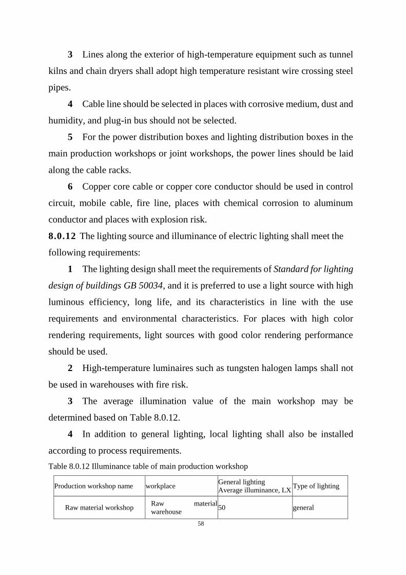
58
3 Lines along the exterior of high-temperature equipment such as tunnel
kilns and chain dryers shall adopt high temperature resistant wire crossing steel
pipes.
4 Cable line should be selected in places with corrosive medium, dust and
humidity, and plug-in bus should not be selected.
5 For the power distribution boxes and lighting distribution boxes in the
main production workshops or joint workshops, the power lines should be laid
along the cable racks.
6 Copper core cable or copper core conductor should be used in control
circuit, mobile cable, fire line, places with chemical corrosion to aluminum
conductor and places with explosion risk.
8.0.12 The lighting source and illuminance of electric lighting shall meet the
following requirements:
1 The lighting design shall meet the requirements of Standard for lighting
design of buildings GB 50034, and it is preferred to use a light source with high
luminous efficiency, long life, and its characteristics in line with the use
requirements and environmental characteristics. For places with high color
rendering requirements, light sources with good color rendering performance
should be used.
2 High-temperature luminaires such as tungsten halogen lamps shall not
be used in warehouses with fire risk.
3 The average illumination value of the main workshop may be
determined based on Table 8.0.12.
4 In addition to general lighting, local lighting shall also be installed
according to process requirements.
Table 8.0.12 Illuminance table of main production workshop
Production workshop name workplace General lighting
Average illuminance, LX Type of lighting
Raw material workshop Raw material
warehouse 50 general
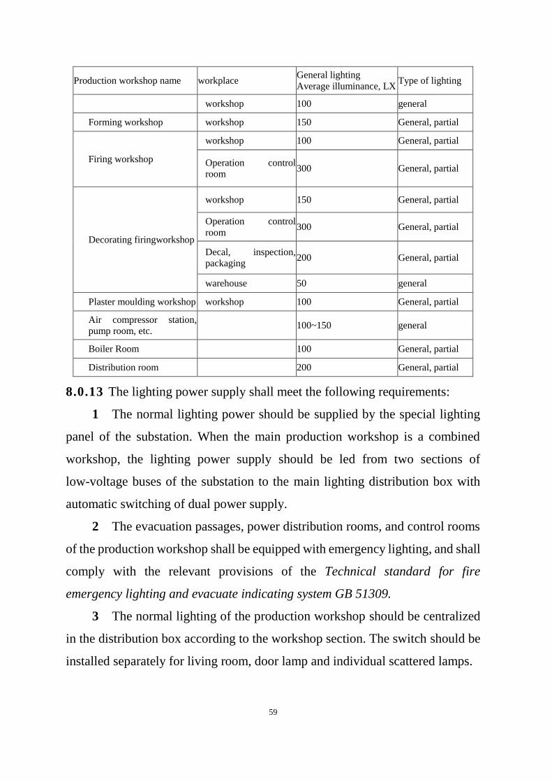
59
Production workshop name workplace General lighting
Average illuminance, LX Type of lighting
workshop 100 general
Forming workshop workshop 150 General, partial
Firing workshop
workshop 100 General, partial
Operation control
room 300 General, partial
Decorating firingworkshop
workshop 150 General, partial
Operation control
room 300 General, partial
Decal, inspection,
packaging 200 General, partial
warehouse 50 general
Plaster moulding workshop workshop 100 General, partial
Air compressor station,
pump room, etc.
100~150 general
Boiler Room 100 General, partial
Distribution room 200 General, partial
8.0.13 The lighting power supply shall meet the following requirements:
1 The normal lighting power should be supplied by the special lighting
panel of the substation. When the main production workshop is a combined
workshop, the lighting power supply should be led from two sections of
low-voltage buses of the substation to the main lighting distribution box with
automatic switching of dual power supply.
2 The evacuation passages, power distribution rooms, and control rooms
of the production workshop shall be equipped with emergency lighting, and shall
comply with the relevant provisions of the Technical standard for fire
emergency lighting and evacuate indicating system GB 51309.
3 The normal lighting of the production workshop should be centralized
in the distribution box according to the workshop section. The switch should be
installed separately for living room, door lamp and individual scattered lamps.

60
The division and control of lighting circuit shall be adapted to the process
flow and equipment layout, and the power saving, wire saving and construction
installation and maintenance shall be considered.
4 The lighting voltage on the local lighting lamp on the equipment and
the side wall of the trench side of the tunnel kiln shall be 36V. The lighting
voltage on the maintenance in the boiler, chain dryer, ball mill, slip tank, and the
spray drying tower shall be 12V.
8.0.14 The lightning protection of buildings (structures) shall designed in
accordance with the relevant provisions of Design code for protection of
Structures against lightning GB 50057. The explosion hazardous places such
as gas station, gas station and gas distribution station shall be designed
according to the Category Two of buildings
8.0.15 Fuel gas alert system shall be set in related place in accordance with
provisions of Code for design of city gas GB 50028.
61
9 A u to ma t i c co n tro l in s t r u me n t a n d i n fo r ma t i o n
9.0.1 The design of the automatic control instrument of the domestic ceramic
plant shall meet the process design requirements and follow the following
principles:
1 The overall automation, informatization, and intelligence level of the
project shall be determined according to factors such as plant scale,
technological equipment level, production process characteristics, product
quality assurance, energy saving and consumption reduction, environmental
protection, and production operation requirements.
2 The production system should be equipped with necessary metering,
testing, monitoring and information transmission instruments.
3 The setting of test items and the design of control system should fully
consider the requirements of automation and intelligence; the instrument series,
varieties and specifications should be unified.
4 The accuracy of automatic control instruments shall be selected
according to the requirements of the process and mainstream product standards.
The process parameter instrument should be 1.5 and above, and the main
economic analysis instrument should be 1.0 and above.
5 Corresponding instruments shall be selected to meet the requirements
of the current national standards based on the classification of the hazardous
area.
6 The protection level of the instrument shall comply with the relevant
regulations of the current national standards, and the protection level of the
instrument installed on site should not be lower than IP65.
9.0.2 The main thermal equipment such as glaze firing kiln, biscuit firing
kiln, decorating firing kiln, spray dryer, hot blast stove, etc. shall be equipped
with oil, gas and other metering instruments. Thermal equipment that uses gas
62
shall also be equipped with automatic safety interlock devices such as power
shutdown and gas shutoff.
9.0.3 The design of automatic control instruments should adopt a distributed
control system (DCS), and set up a computer control system (MIS) for
plant-wide production scheduling and management.
9.0.4 Isolation device shall be installed for fuel oil pressure measurement.
Diaphragm pressure gauge and isolation diaphragm pressure transmitter
should be adopted for pressure measurement.
9.0.5 For the automatic control system based on switch value and sequence
control, programmed logic control (PLC) should be used, with three operation
modes of manual, semi-automatic and full-automatic.
9.0.6 The tunnel kiln entry and exit vehicle control system should be
equipped with a separate operation bench.
9.0.7 For the cable protection mode from the primary element and actuator to
the cable duct, the metal hose with a length of about 500mm should be used,
and the wire protection pipe should be put into the wire duct.
9.0.8 The grounding connection of instrument and control system should be
classified and collected, and finally equipotential connection with the main
grounding plate, and the grounding device should be shared with electrical
devices.
9.0.9 The grounding resistance of the common grounding system of the
instrument system shall not be greater than 1Ω, and the separate grounding
resistance of the instrument system shall not be greater than 4Ω.
9.0.10 The burning workshop and gas station shall be equipped with
instrument control room respectively, and the location shall be in accordance
with the process layout requirements. Location with frequent production
operation, centralized control points, convenient operation and good
ventilation shall be selected
63
9.0.11 The general inspection and control items of main production systems
and equipment may be determined according to the following principles:
1 Tunnel kiln inspection and control items are shown in Table 9.0.11-1.
2 Roller kiln inspection and control items are shown in Table 9.0.11-2.
3 The thermal detection and control items of the producer gas station are
shown in Table 9.0.11-3.
9.0.12 Telephone and network communication system shall be set in the
plant area, and the standby capacity of telephone system shall not be less than
20%
9.0.13 The design of telephone and network communication system in the
plant shall comply with provisons of national standard Code for engineering
design of generic cabling system GB50311.

64
Table 9.0.11-1 Measuring & Control Points List of Tunnel Kiln
M e a s u r i n g
& C o n t r o l
p o i n t
F i e l d
i n d i c a t o r
I n s t r u m e n t p a n e l
I n s t r u c t i o n s r e c o r d i n g I n t e g r a t i n g I n t e r l o c k A l a r m c o n t r o l
F l u e d u c t
t e m p e r a t u r e √
F l u e d u c t
p r e s s u r e √
K i l n r o o f
t e m p . a t
p r e h e a t i n g
s e c t i o n
√
K i l n w a l l
p r e s s u r e a t
p r e h e a t i n g
s e c t i o n
√
U p p e r &
l o w e r p a r t
t e m p . a t
p r e h e a t i n g
s e c t i o n
√
K i l n r o o f
t e m p . a t
f i r i n g
s e c t i o n
√ √ √
K i l n w a l l
p r e s s u r e a t
f i r i n g
s e c t i o n
√
U p p e r &
l o w e r t e m p .
a t f i r i n g
s e c t i o n
√
U n d e r - c a r
t e m p . a t
f i r i n g
s e c t i o n
√
K i l n w a l l
p r e s s u r e a t
c o o l i n g
s e c t i o n
√
P r e s s u r e
o f a l l f a n s √
C a r s
e n t e r i n g &
e x i t i n g
√ √ √
G a s o r
l i q u i d f u e l
f l o w i n
h e a d e r p i p e
√ √
G a s o r
l i q u i d f u e l
p r e s s u r e i n
√ √ √ √

65
M e a s u r i n g
& C o n t r o l
p o i n t
F i e l d
i n d i c a t o r
I n s t r u m e n t p a n e l
I n s t r u c t i o n s r e c o r d i n g I n t e g r a t i n g I n t e r l o c k A l a r m c o n t r o l
h e a d e r p i p e
P r e s s u r e
o f e a c h g a s
p i p e r i n g
√ √ √ √
P o w e r
f a i l u r e
p r o t e c t i o n
o f g a s
h e a d e r p i p e
F u e l o i l
h e a d e r p i p e
t e m p .
√ √
P r e s s u r e
o f
c o m b u s t i o n
a i r d u c t
√ √
C o m b u s t i o
n a i r d u c t
t e m p e r a t u r e
√ √
T a b l e 9 . 0 . 1 1 - 2 M e a s u r i n g a n d C o n t r o l P o i n t s L i s t o f R o l l e r
K i l n
M e a s u r i n g & C o n t r o l p o i n t F i e l d
i n d i c a t o r
d a s h b o a r d
I n s t r
u c t i o
n s
r e c o r
d i n g
I n t e g
r a t i n
g
I n t e r
l o c k
A l a r
m
c o n t r
o l
Flue duct temperature √
Flue duct pressure √
Upper part temperature √
Upper part pressure √
Lower part temperature √
Lower part pressure √
Kiln temperature √ √ √
Kiln pressure √
Pressure of all fans √
Roller bed operation speed √
Operation condition of entering &
exiting kiln
√ √ √
Operation condition outside kiln √ √ √
Gas or liquid fuel flow in header pipe √ √
Gas or liquid fuel pressure in header
pipe
√ √ √ √
Power failure protection of gas header
pipe
√ √
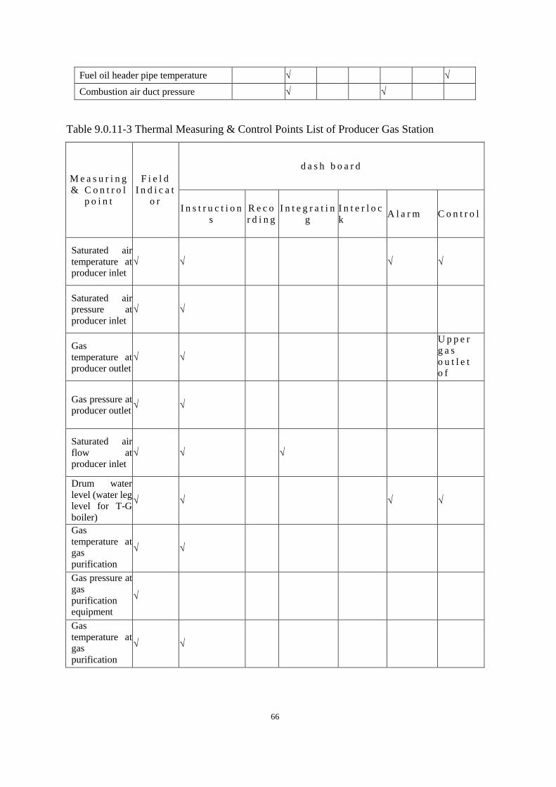
66
Fuel oil header pipe temperature √ √
Combustion air duct pressure √ √
Table 9.0.11-3 Thermal Measuring & Control Points List of Producer Gas Station
M e a s u r i n g
& C o n t r o l
p o i n t
F i e l d
I n d i c a t
o r
d a s h b o a r d
I n s t r u c t i o n
s
R e c o
r d i n g
I n t e g r a t i n
g
I n t e r l o c
k A l a r m C o n t r o l
Saturated air
temperature at
producer inlet
√ √ √ √
Saturated air
pressure at
producer inlet
√ √
Gas
temperature at
producer outlet
√ √
U p p e r
g a s
o u t l e t
o f
t w o - s t a
g e
f u r n a c e
T e m p e r
a t u r e
n e e d s t o
b e
a d j u s t e
d
a u t o m a t
i c a l l y
Gas pressure at
producer outlet √ √
Saturated air
flow at
producer inlet
√ √ √
Drum water
level (water leg
level for T-G
boiler)
√ √ √ √
Gas
temperature at
gas
purification
equipment
inlet
√ √
Gas pressure at
gas
purification
equipment
inlet
√
Gas
temperature at
gas
purification
equipment
outlet
√ √

67
M e a s u r i n g
& C o n t r o l
p o i n t
F i e l d
I n d i c a t
o r
d a s h b o a r d
I n s t r u c t i o n
s
R e c o
r d i n g
I n t e g r a t i n
g
I n t e r l o c
k A l a r m C o n t r o l
Gas pressure at
gas
purification
equipment
outlet
√ √
Air header
pressure √ √ √ √ √
Air pressure at
blower outlet √ √
Low pressure
header gas
pressure
√ √ √ √ √
Gas pressure at
gas exhauster
outlet
√ √ √
Gas pressure at
gas station
outlet
√ √
Gas
temperature at
outlet gas
station
√ √
Outlet gas flow
of gas station √ √
Circulating
water
temperature
√
Circulating
water pressure √
Circulating
water flow √
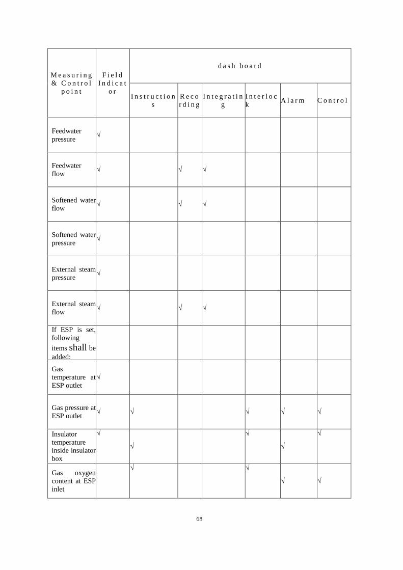
68
M e a s u r i n g
& C o n t r o l
p o i n t
F i e l d
I n d i c a t
o r
d a s h b o a r d
I n s t r u c t i o n
s
R e c o
r d i n g
I n t e g r a t i n
g
I n t e r l o c
k A l a r m C o n t r o l
Feedwater
pressure √
Feedwater
flow √ √ √
Softened water
flow √ √ √
Softened water
pressure √
External steam
pressure √
External steam
flow √ √ √
If ESP is set,
following
items shall be
added:
Gas
temperature at
ESP outlet
√
Gas pressure at
ESP outlet √ √ √ √ √
Insulator
temperature
inside insulator
box
√
√
√
√
√
Gas oxygen
content at ESP
inlet
√ √
√ √
69
10 A r ch i t e c tu r e an d S tr uc tu r e
10.1 A r c h i t e c t u r e
10.1.1 The architectural design for domestic ceramic plant building shall meet
the requirements of technological design and the requirements of regional
planning. In combination with the local meteorological conditions and
environmental conditions, the following issues shall be taken into consideration:
internal transport, sanitary facilities, safety, fire prevention, water prevention,
corrosion prevention, noise prevention, dust prevention, thermal insulation, heat
insulation, ventilation and natural lighting.
10.1.2 Pay attention to prevent possible iron rust in raw materials workshop.
All the exposed ferrous components of the building, incl. steel doors & windows,
hardware, platform, handrail and etc., shall be prevented from rust.
Steel doors and windows should not be used in the raw materials workshop.
There shall be a foot (shoe) wash basin at the entrance.
10.1.3 For plants with lots of dust such as the raw materials workshop and
Forming workshop, the indoor building components shall reduce the parts that
are easy to accumulate dust. The inner surfaces of walls and roofs shall be
smooth and flat. The dust generation parts should be properly sealed to reduce
diffusion.
10.1.4 For raw material plant, forming workshop and decorating Firing
workshop, the floor and ground shall be flat and dense to prevent dust and be
easy to clean. The floor surface shall be designed with an appropriate drainage
slope to drain to the trench or floor drain.
10.1.5 Raw material plant, aging room and preform body room shall be kept
away from direct sunlight and straight ventilation, and appropriate temperature

70
and humidity shall be maintained. Walls and floors shall be flat, smooth and
wear-resistant.
10.1.6 Inside Forming workshop, Firing workshop and Decorating Firing
workshop, major operating locations with lots of operators shall be provided
with good natural lighting and natural ventilation, and direct sunlight shall be
avoided.
Ventilation measures shall be strengthened in the painting section, and air
conditioner should be arranged. And no matter natural or mechanical ventilation,
direct blowing to the operating platform shall be avoided.
10.1.7 For Decorating firing workshop with large amount of liquid gold, the
storage room for liquid gold shall be designed as for valuables.
10.1.8 For large noise sources such as fans and air compressors, effective
building sound insulation measures shall be taken.
10.1.9 In firing and Decorating firing workshop, skylight, ventilator and high
side window shall be set above the kiln, which is the centralized source of heat.
10.1.10 Each production workshop shall set up auxiliary rooms such as
workshop offices, cloakrooms, rest rooms, shower rooms, and toilets in
accordance with production characteristics, actual needs and the principle of
convenience. Workshops with more concentrated female workers shall set up
separate female worker clinics. The setting standard of the bathroom in the
workshop may be determined according to Table 10.1.10.
Table 10.1.10 Shower room standard for each workshop
n a t u r e W o r k s h o p o r
s e c t i o n
E a c h s h o w e r
N u m b e r o f
u s e r s ( p e o p l e )
R e m a r k s
H i g h
t e m p e r a t u r e
o p e r a t i o n
F i r i n g w o r k s h o p
D e c o r a t i n g f i r i n g
k i l n
5 ~ 8 E q u i p p e d w i t h
s h o w e r r o o m

71
D u s t y
o p e r a t i o n s
R a w m a t e r i a l
w o r k s h o p
F o r m i n g w o r k s h o p
P l a s t e r m o u l d i n g
w o r k s h o p , e t c .
9 ~ 1 2
10.1.11 When the form of a joint plant building is adopted, in addition to
meeting the requirements of smooth process flow, attention shall be paid to
meeting the functional requirements of each part, and the problems of ventilation
and lighting shall be solved.
10.1.12 The operation layer of the main building of the gas station should be
enclosed. The coal storage layer shall consider explosion-proof or venting
measures, and there should be no less than two safety exits on each layer.
10.1.13 Architectural design shall comply with relevant regulations of the
current Code for Fire Protection Design of Buildings GB 50016. Fire hazard
classification of each building during the production process may be determined
in accordance with Table 10.1.13.
Table 10.1.13 Classification of building fire hazards
B u i l d i n g ( s t r u c t u r e ) n a m e P r o d u c t i o n c a t e g o r y
P r o d u c t i o n w o r k s h o p
R a w m a t e r i a l w o r k s h o p Ⅴ
F o r m i n g w o r k s h o p Ⅳ
F i r i n g w o r k s h o p Ⅳ
D e c o r a t i n g f i r i n g w o r k s h o p I I I
P l a s t e r m o u l d i n g w o r k s h o p V
C e n t r a l l a b o r a t o r y a n d R & D
c e n t e r Ⅳ
P r o d u c t i o n a u x i l i a r y b u i l d i n g
B o i l e r R o o m Ⅳ
M e c h a n i c a l r e p a i r r o o m V
E l e c t r i c r e p a i r r o o m , i n s t r u m e n t
r e p a i r r o o m I I I
S u b s t a t i o n I I I

72
A i r c o m p r e s s o r s t a t i o n V
P r o d u c e r g a s s t a t i o n I I
W a t e r g a s s t a t i o n I
S e m i - w a t e r g a s s t a t i o n I I
G a s d i s t r i b u t i o n s t a t i o n I
F u e l o i l d e p o t I I I
A l l k i n d s o f p u m p h o u s e s V
N o t e : M i n i m u m f i r e r e s i s t a n c e r a t i n g o f b u i l d i n g a n d s t r u c t u r e i s
g r a d e Ⅱ .
10.2 S t r u c t u r e
10.2.1 The production workshop of a daily-use ceramic plant shall select a
reasonable structure according to the characteristics of the production process,
and the structure layout should meet the requirements of the production process
and should conform to the uniform modulus of the building. Steel structure
should not be used when iron contamination of semi-finished mud products may
occur, otherwise effective anti-corrosion measures shall be taken.
10.2.2 Structural safety class of all production & ancillary buildings and
auxiliary facilities shall be no less than class Ⅱ, and seismic fortification
intensity no less than class Ⅲ.
10.2.3 Effective thermal insulation measures shall be taken for those structural
elements nearby the thermal equipment such as kiln in accordance with the
required standards and codes, or heat-proof materials shall be used.
10.2.4 Surface of retaining wall for raw material workshop bearing horizontal
thrust shall be flat and smooth, and should be with no vertical or transverse rib.
10.2.5 The foundations of large-vibration equipment such as ball mills and air
compressors shall not be connected to the plant foundation and other adjacent
underground facilities. When the foundation is too close, appropriate vibration
isolation measures shall be taken.
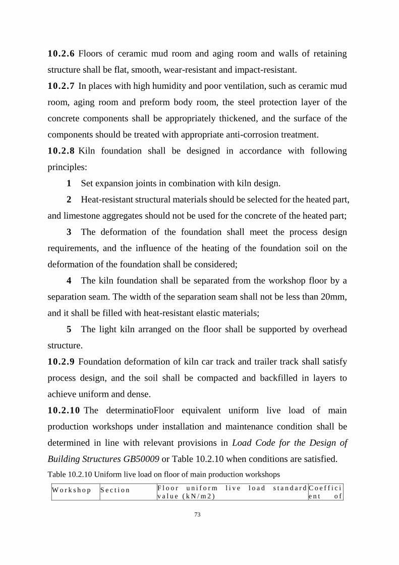
73
10.2.6 Floors of ceramic mud room and aging room and walls of retaining
structure shall be flat, smooth, wear-resistant and impact-resistant.
10.2.7 In places with high humidity and poor ventilation, such as ceramic mud
room, aging room and preform body room, the steel protection layer of the
concrete components shall be appropriately thickened, and the surface of the
components should be treated with appropriate anti-corrosion treatment.
10.2.8 Kiln foundation shall be designed in accordance with following
principles:
1 Set expansion joints in combination with kiln design.
2 Heat-resistant structural materials should be selected for the heated part,
and limestone aggregates should not be used for the concrete of the heated part;
3 The deformation of the foundation shall meet the process design
requirements, and the influence of the heating of the foundation soil on the
deformation of the foundation shall be considered;
4 The kiln foundation shall be separated from the workshop floor by a
separation seam. The width of the separation seam shall not be less than 20mm,
and it shall be filled with heat-resistant elastic materials;
5 The light kiln arranged on the floor shall be supported by overhead
structure.
10.2.9 Foundation deformation of kiln car track and trailer track shall satisfy
process design, and the soil shall be compacted and backfilled in layers to
achieve uniform and dense.
10.2.10 The determinatioFloor equivalent uniform live load of main
production workshops under installation and maintenance condition shall be
determined in line with relevant provisions in Load Code for the Design of
Building Structures GB50009 or Table 10.2.10 when conditions are satisfied.
Table 10.2.10 Uniform live load on floor of main production workshops
W o r k s h o p S e c t i o n F l o o r u n i f o r m l i v e l o a d s t a n d a r d
v a l u e ( k N / m 2 )
C o e f f i c i
e n t o f

74
S l a b S e c o n d a r y
b e a m
Ma
in b
ea
m
p e r m a n e
n t Ψ g
S p a n
≥ 1 . 2 m
S p a n
≥ 2 . 0 m
s p a c i n g
≥ 2 1 . 2 m
s p a c i n
g
≥ 2 . 0 m
R a w
m a t e r i a l
w o r k s h o p
B a l l m i l l
p l a t f o r m
P u g g i n g
s e c t i o n
F i l t e r p r e s s
s e c t i o n
C e r a m i c
m u d r o o m
1 8
1 5
1 5
1 5
1 2
1 2
1 2
1 0
1 0
1 0
8
8
1 0
8
8 0 . 6 5
F o r m i n g
w o r k s h o p
F o r m i n g ,
g l a z i n g
P r e f o r m
b o d y
w a r e h o u s e
1 5
1 5
1 2
1 2
1 0
1 0
8
8
8
8
0 . 7 5
0 . 8 5
F i r i n g
w o r k s h o p
W h i t e
p o r c e l a i n
i n s p e c t i o n
W h i t e
p o r c e l a i n
s t o r a g e
1 5
1 8
1 2
1 5
1 0
1 2
8
1 0
8
1 0
0 . 7 5
0 . 8 5
d e c o r a t i n g
f i r i n g w o r k s
h o p
C o l o r
d e c o r a t i o n
s e c t i o n
D e c o r a t i n g
f i r i n g
P a c k i n g
s e c t i o n
F i n i s h e d
p r o d u c t
w a r e h o u s e
1 2
1 2
1 5
2 0
1 0
1 0
1 2
1 6
8
8
1 0
1 4
7
7
8
1 2
7
7
8
1 2
0 . 6 5
0 . 6 5
0 . 6 5
0 . 8 5
Note: When the production process has special requirements or reliable basis, the load value in
the above table may be adjusted reasonably.
10.2.11 Dynamic coefficient for main common equipment may be determined
based on the Table 10.2.11.
Table 10.2.11 Dynamic coefficient list for main common equipment
Equipment name Dynamic coefficient
Hammer crusher 3.0~4.5
Roll crusher 2.0
Electromagnetic vibration feeder 1.2
Single tube screw feeder 1.3
Bucket elevator 1.3
Belt conveyor 1.2
Stationary screen 1.5
Vibrating screen 2.0
Water ring vacuum pump or
compressor 1.0~3.0
Sand pump 3.0~3.5
Manual monorail crane 1.1
75
Electric hoist 1.2
Bridge crane 1.2
11 Wa te r S u pp ly a n d D ra i nag e
11.0.1 The design of water supply and drainage for domestic ceramics factory
shall meet the demand of safe production, firefighting and domestic water in the
factory, choose the water source properly and increase its reutilization by using
advanced technology so as to achieve environmental protection, economy,
safety and reliability.
11.0.2 Water supply & drainage system shall be planned according to the plant
capacity, with appropriate allowance. For expansion or reconstruction projects,
existing facilities, adjacent public utilities and water supply & drainage facilities
from other industrial enterprises in the same area shall be fully utilized, on the
premise of meeting relevant authorities’ requirements.
11.0.3 Water consumption of workshop production as well as its quality and
pressure shall be determined in accordance with process requirements. In
general, the water quality shall meet the drinking water quality standard, with
iron content strictly controlled and turbidity limit extended to 20mg/L. The
water pressure at the inlet of the workshop shall be 0.25~0.3MPa. In case some
equipment requires higher water pressure, .0.25~0.3MPa booster facilities shall
be arranged in the building. If the water pressure of local equipment is high,
pressurization facilities shall be installed in the workshop.
The water inlet pipes and main water-consuming equipment of each
production workshop shall be equipped with metering devices.
11.0.4 Uninterrupted water supply facilities shall be equipped for the producer
water of gas station.

76
11.0.5 Service water consumption of water treatment, unforeseen water
consumption and water leakage loss in pipeline network shall be subject to Code
for design of outdoor water supply engineer GB50013.
11.0.6 Water supply pipe network inside the plant shall be laid in a circular way
around the main production workshops and in other workshops it may be laid in
branches.
11.0.7 Drainage system design shall follow the principle of dividing the rinsing
from turbidity.General drainage shall be designed in accordance with relevant
provisions. And design of harmful sewage disposal shall be subject to
requirements in Chapter 16.
12 He a t i n g v e n t i la t io n a n d a i r co n d i t i o n i ng
12.0.1 HVAC design of domestic ceramics plant shall meet the process
engineering requirement and should include heating, ventilation, air
conditioning and dust removal.
12.0.2 Besides meeting the requirements of process and equipment, HVAC
design shall also take energy-saving, working conditions improvement and
environmental protection into consideration.
12.0.3 Central heating and air conditioning should be designed for those
plants and buildings having certain requirement for heating and air
conditioning in production or life.
12.0.4 Design calculated indoor (working zone) temperature of production
workshop and auxiliary workshop in winter and summer may be determined
as in Table 12.0.4.
Table 12.0.4 Indoor design temperature limit in winter and summer
W o r k s h o p
n a m e S e c t i o n n a m e
I n d o o r d e s i g n
t e m p e r a t u r e
l i m i t i n
h e a t i n g
s e a s o n ℃
T h e d i f f e r e n c e
b e t w e e n t h e
s u m m e r w o r k i n g
p l a c e t e m p e r a t u r e
a n d t h e c a l c u l a t e d
o u t d o o r
t e m p e r a t u r e ℃
R a w m a t e r i a l
w o r k s h o p O p e r a t i o n l a y e r 1 0 ~ 1 2 3

77
W o r k s h o p
n a m e S e c t i o n n a m e
I n d o o r d e s i g n
t e m p e r a t u r e
l i m i t i n
h e a t i n g
s e a s o n ℃
T h e d i f f e r e n c e
b e t w e e n t h e
s u m m e r w o r k i n g
p l a c e t e m p e r a t u r e
a n d t h e c a l c u l a t e d
o u t d o o r
t e m p e r a t u r e ℃
M u d s t o r a g e & a g i n g
r o o m 5 ~ 8
F o r m i n g
w o r k s h o p
P l a s t i c f o r m i n g s e c t i o n ,
i s o s t a t i c p r e s s i n g
s e c t i o n
1 6 ~ 1 8 3
G r o u t i n g s e c t i o n ,
g l a z i n g s e c t i o n 1 8 ~ 2 0
3
F i r i n g
w o r k s h o p
B i s c u i t f i r i n g s e c t i o n
G l a z e f i r i n g s e c t i o n
N o h e a t i n g
i n c o l d
a r e a s ,
p a r t i a l
h e a t i n g i n
s e v e r e c o l d
a r e a s
7
P o l i s h i n g s e c t i o n w h i t e
p o r c e l a i n i n s p e c t i o n
s e c t i o n
1 2 ~ 1 4 3
D e c o r a t i n g
f i r i n g w o r k s h
o p
D e c o r a t i n g s e c t i o n 1 8 ~ 2 0
R o o m t e m p e r a t u r e
2 6 ~ 2 8
O r f o l l o w p r o c e s s
r e q u i r e m e n t s
F i r i n g s e c t i o n 1 2 - 1 4 5
P a c k i n g s e c t i o n 1 2 ~ 1 4 R o o m t e m p e r a t u r e
2 6 ~ 2 8
Plaster model
workshop
Mold casting section
Master mould section 16~18 3
Master mold and model mold room 8~10 3
Central laboratory
16~18 Follow the process
requirement
R&D Center
Product design room 18 Room temperature 26~28
Other rooms See each section
of each workshop
Each workshop
Or section
Instrument Control Room 18 Room temperature 26~28
Low-voltage power distribution
room 16
Follow the electrical
requirements
Producer
Gas station
Bottom layer 10 3
Operation layer 12~14 5
Top coal bunker 5 3
Machine room 12~14 3
12.0.5 The heating and ventilation design of the raw material workshop shall
meet the following requirements:
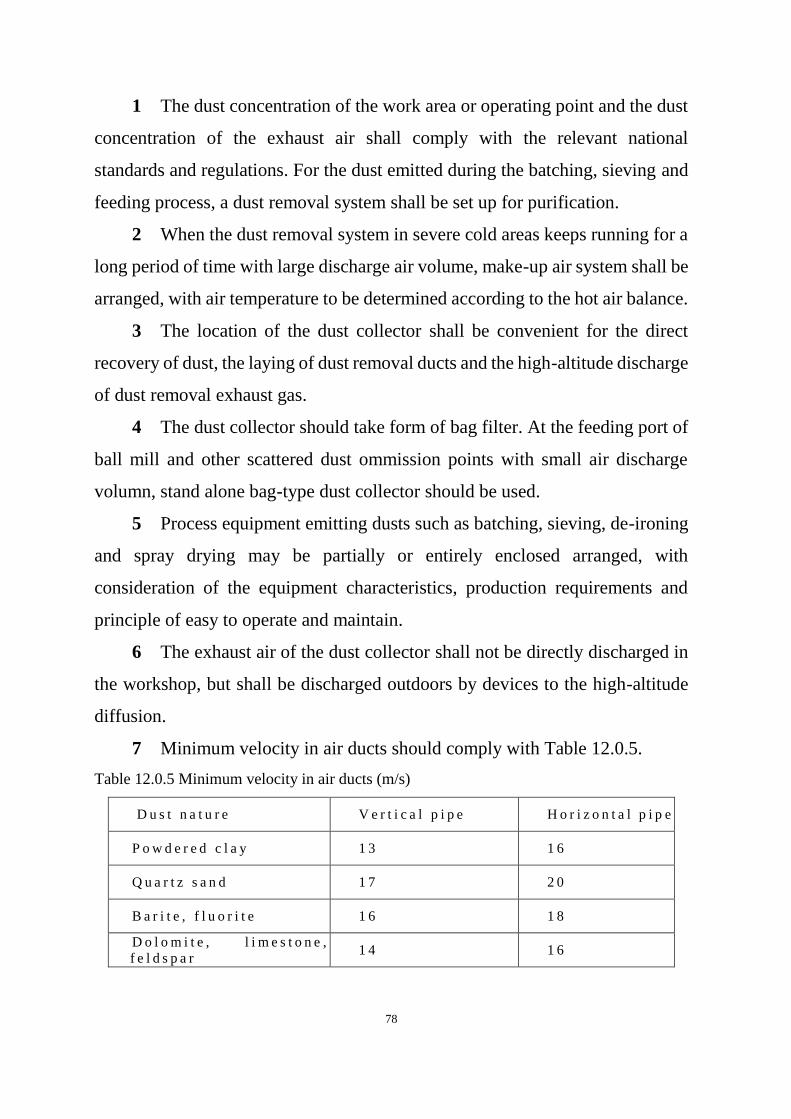
78
1 The dust concentration of the work area or operating point and the dust
concentration of the exhaust air shall comply with the relevant national
standards and regulations. For the dust emitted during the batching, sieving and
feeding process, a dust removal system shall be set up for purification.
2 When the dust removal system in severe cold areas keeps running for a
long period of time with large discharge air volume, make-up air system shall be
arranged, with air temperature to be determined according to the hot air balance.
3 The location of the dust collector shall be convenient for the direct
recovery of dust, the laying of dust removal ducts and the high-altitude discharge
of dust removal exhaust gas.
4 The dust collector should take form of bag filter. At the feeding port of
ball mill and other scattered dust ommission points with small air discharge
volumn, stand alone bag-type dust collector should be used.
5 Process equipment emitting dusts such as batching, sieving, de-ironing
and spray drying may be partially or entirely enclosed arranged, with
consideration of the equipment characteristics, production requirements and
principle of easy to operate and maintain.
6 The exhaust air of the dust collector shall not be directly discharged in
the workshop, but shall be discharged outdoors by devices to the high-altitude
diffusion.
7 Minimum velocity in air ducts should comply with Table 12.0.5.
Table 12.0.5 Minimum velocity in air ducts (m/s)
D u s t n a t u r e V e r t i c a l p i p e H o r i z o n t a l p i p e
P o w d e r e d c l a y 1 3 1 6
Q u a r t z s a n d 1 7 2 0
B a r i t e , f l u o r i t e 1 6 1 8
D o l o m i t e , l i m e s t o n e ,
f e l d s p a r 1 4 1 6

79
8 The raw material workshop should preferentially adopt natural
ventilation in summer.. The overall ventilation volumne of the workshop should
be calculated based on the elimination of waste heat and waste humidity.
Mechanical ventilation shall be used when natural ventilation cannot meet the
requirements.
12.0.6 The heating and ventilation design of the Forming workshop shall
meet the following requirements
1 The Forming workshop shall have good ventilation condition. Natural
ventilation should be adopted, and mechanical ventilation shall be adopted when
natural ventilation cannot meet the requirements.
2 For drying equipment such as chain dryers and chamber drying rooms,
the waste heat and waste damp air shall be discharged outdoors.
3 In the working place where workers in the Forming workshop stay for a
long time, under the conditions of outdoor ventilation calculation temperature,
when the ambient air temperature exceeds 35℃, local air supply or local cold air
supply shall be provided.
4 The Forming workshop should be heated by a radiator.
5 The glazing section should be equipped with natural ventilation or
mechanical ventilation in summer. When the process production requires the
glazing workshop to be semi-enclosed or fully enclosed, the glazing section
should be equipped with a local cooling air system.
When glaze spraying is used in the glaze application section, a wet dust
removal system should be installed, and the dust-containing sewage treatment
shall be included in the wastewater treatment system.
6 Bag filter shall be equipped for dry trimming, with discharge air
volume of each trimming point at 800 m3/h~1200m
3/h. And side suction should
be adopted for dust hood.
80
12.0.7 Heating and ventilation design of Firing workshop shall meet the
following requirements:
1 Natural ventilation should be preferentially adopted in the Firing
workshop.. When natural ventilation fails to meet hygienic requirements,
mechanical ventilation should be supplemented.
2 The biscuit and glaze firing sections in severe cold areas should adopt
wind shelter skylights with operatable saches, and wind shelter skylights with
rain-proof measures shall be adopted in other areas.
3 In areas with greater wind and sand, it is not advised to have open
skylights in the workshops producing high-grade fine porcelain. In summer,
mechanical ventilation shall be adopted, and the overall ventilation rate of the
workshop should be calculated according to the elimination of waste heat and
humidity in the workshop.
4 The loading and unloading work area of the Firing workshop should be
equipped with local air supply, and mobile post air blowers may be arranged if
needed.
5 Kiln flue gas should be utilized for heating in winter.
6 Dust removal system shall be installed for polishing and bottom
grinding, and bag type filter is preferred. The suction hood should be set up with
side suction, and the air volume of each dust suction point shall be 600
m3/h~800m
3/h.
7 If a fuel oil pump room is installed in the Firing workshop, the
ventilation rate shall be the larger of the following two calculation results:
1) Ventilation volume needed for eliminating waste heat;
2) Ventilation rate no less than 10 times per hour.
8 Ventilation design of oil pump house shall comply with the requirement
that hydrocarbone content in air shall not exceed 350mg/m3 and volume
81
concentration shall be not more than 0.2%, and discharge air of mechanical
ventilation shall be 10%~20% larger than its air feed.
12.0.8 The heating, ventilation and air conditioning design of the Decorating
Firing workshop shall meet the following requirements:
1 The Decorating Firing workshop shall be equipped with ventilation
measures to remove the waste heat and waste gas from the workshop, and
natural ventilation and mechanical ventilation should be combined.
2 A combination of natural ventilation and mechanical ventilation should
be used in the decorating firing section, and ventilation rate shall not be less than
5 per hour. Local air supply should be provided in the porcelain loading and
unloading work area.
3 Mechanical ventilation supplemented by natural ventilation shall be
adopted for decorating section with ventilation rate of no less than 3 times per
hour. Air-conditioner or cold air supply system may be set to keep the indoor
temperature at 26~28℃ in summer.
4 Air supply system shall be designed to supply air to the operating area
after coarse or medium efficiency filtration, which can prevent iron dust getting
into the workshop. The air duct and air outlet should not be made of steel plate.
12.0.9 Packing section should be equipped with air-conditioning system in
summer, and the indoor design temperature is 26~28℃.
12.0.10 Ventilation rate of Plaster moulding workshop in summer shall be no
less than 3 times per hour.
12.0.11 The heating, ventilation and air conditioning design of auxiliary
workshops and auxiliary buildings shall meet the following requirements:
1 Heating, ventilation and dust removal design of producer gas station
shall comply with the current national codes and standards. Explosion proof
measures shall be taken for the ventilation of machinery room. Heat dissipating
capacity of equipment at bottom floor takes 20% for heating load calculation.

82
2 Heating and ventilation design of air compressor room shall conform to
relevant regulations in Code for Design of Compressed Air Station GB 50029.
3 Compressed air stations in hot areas or workshops with heat intensity
greater than 35W/m3 shall use natural ventilation or mechanical ventilation to
eliminate waste heat.
4 Fume hoods shall be set up in the central laboratory and workshop
laboratory. The exhaust outlet of the air duct of the fume hood shall be higher
than 0.5m above the roof.
5 Ventilation rate of chlorine dosing room in pump house shall be no less
than 15 times per hour, with 1/3 of air discharged from the upper part of the room
whereas the other 2/3 from the lower part of the room.
6 The R&D center should be equipped with an air-conditioning system in
summer, and the indoor design temperature is 26~28℃.
7 For instrument control room equipped with air conditioning or
mechanical ventilation, the room shall maintain micro-positive pressure.
13 Fi r e f i gh t i ng
13.0.1 Fire-fighting design shall comply with provisions of Code for Design
on Fire Protection and Fire Prevention GB 50016, Technical code for fire
protection water supply and hydrant systems GB 50974 and other relevant
standards and codes.
13.0.2 Fire dikes shall be set up in the oil tank area. The design of the fire dike
shall comply with the requirements of in the Code for Design of Fire Dike in
Storage Tank Area GB 50351.
13.0.3 The fire protection design of the factory’s power distribution facilities
shall be implemented in accordance with the Code for fire-protection design
of power plant and substation GB50229.

83
13.0.4 Automatic fire alarm system shall be equipped for each finished
products warehouse and packaging material warehouse with plant area larger
than 1500m2 or gross building area more than 3000m
2.
84
14 En e rg y s av i n g
14.1 G e n e r a l p r o v i s i o n s
14.1.1 The design of the domestic ceramics plant shall comply with the
national laws, regulations, rules, codes and standards concerning energy saving
and comprehensive utilization of resources.
14.1.2 While preparing the basic design documents, the chapters or special
article on energy saving shall be prepared.The energy saving assessment of the
project shall be completed along with the basic design, and the energy saving
assessment report shall be prepared according to the relevant requirement.
14.1.3 Review comments on basic design and energy saving assessment report
shall be processed during detail design. Any changes to the approved
energy-saving design scheme shall be submitted for re-assessment and approval.
14.1.4 Technology and equipment about low carbon emission and
energy-saving promoted by the nation shall be actively adopted in the design of
domestic ceramic plant.
14.2 P r o c e s s e n e r g y s a v i n g
14.2.1 Select energy-saving type furnace/kiln with optimized structure.
14.2.2 Use advanced combustion device.
14.2.3 Use advanced energy-saving firing technologies such as low
temperature fast firing, single firing, naked burning firing, microwave aid gas
firing (MAGF) and etc..
14.2.4 Use energy-saving combustion technologies such as oxygen-enriched
combustion, high temperature air combustion and etc.
14.2.5 Select high-efficient insulation materials and coating technologies.
14.3 W a s t e h e a t r e c o v e r y
85
14.3.1 Set up heat exchanger to heat combustion air and fuel with waste heat
from flue gas.
14.3.2 Set up preheating section or roller dryer kiln, utilizing flue gas waste
heat to dry wet green ware or heat the air to dry the wet green ware.
14.3.3 Set up HRSG to generate steam by utilizing flue gas waste heat; the
steam may be used in power generation, production, daily life, heating and etc.
14.3.4 Waste heat recovery rate of oxidizing flame and reduction flame kiln
(porcelain, stoneware, pottery) shall be no less than 50%.
14.4 E l e c t r i c i t y s a v i n g
14.4.1 Power supply & distribution design shall comply with the following
provisions:
1 The substation or distribution station shall be located close to the load
center, cut down distribution series, shorten supply radius and select low-loss
energy saving transformer.
2 Capacity, numbers and operating mode of transformer shall be
determined in accordance with the character of load.
3 The design of power supply & distribution system should use reactive
compensation both at high voltage side and low voltage side, both centralized
and local, whichever applicable. Power factor at enterprise billing side under
maximum load shall not be less than 0.92.
4 Operating load rate of transformer should be 70~80%.
5 Ultra-harmonics of power system shall be reduced and keep the
three-phase current balance of the transformer.
14.4.2 Electrical equipment selection shall comply with the following
provisions:

86
1 Large capacity motors should be equipped with local capacitance
compensation or phase advancer; motor requiring rotary volicity adjusting
should be equipped with frequency converter.
2 High-efficient energy saving motor shall be used.
3 Appropriate feed size and discharge fineness should be selected for
crush and grinding system.
14.4.3 Energy saving design for lighting shall comply with the following
provisions:
1 Under obtain the required lighting level and visual comfort, efficient,
energy-saving and practical new light sources, lamp electrical accessories,
lighting fittings and controllers shall be adopted.
2 Street lighting controller should be equipped for the road lighting in
plant area, and solar street lighting may be used if possible.
3 Light emitting diode (LED) light source shall be used in small
illumination location such as evacuation indicator light, corridor light, courtyard
light and emergency lighting.

87
15 En vi r o n me n ta l Pro te c t io n
15.1 G e n e r a l p r o v i s i o n s
15.1.1 Design of domestic ceramics plant shall strictly abide by the current
laws and regulations, codes and standards on environmental protection issued by
the nation, industry and local government.
15.1.2 Design of domestic ceramics plant shall adopt new process and
technology and strictly control the generation of pollutants. Measures of
prevention first, prevention and treatment integrated, and comprehensive
utilization shall be taken to eliminate or minimize the pollutants.
15.1.3 Design of domestic ceramics plant shall adopt the effective schemes
with account local conditions, and the same time, considering economis defenits,
environmental benefits and social benefits.
15.2 W a s t e w a t e r
15.2.1 For the slip sewage from production workshop, the suitable treatment
process shall be built according with the sewage flow, sewage compositions and
local environmental requirements. Treated sewage may be reused as rinse water
for floor and sludge may be reclaimed for reutilization after concentration and
dehydration. Unusable wastes shall be harmless treated or sent to special
treatment company.
15.2.2 For the gypsum sewage from Plaster moulding workshop, there is one
sedimentation pond with two grids nearby the workshop,the sewage after
clarifing through this pond shall be discharged. The sediments in pond will be
cleaned manually.
15.3 W a s t e g a s
88
15.3.1 Following waste gas emissions from domestic ceramics plant shall be
controlled and treated:
1 Flue gas generated by thermal equipment;
2 Flue gas generated by boiler;
3 Tail gas from the dust removal system in each production workshop.
15.3.2 In order to eliminate pollutions during the production, thermal
equipment shall be selected with advanced combustion device and clean fuel
using. The flue gas with excessive pollutions shall be treated to reach the
requirements in relavant standard before discharging into atmosphere.
15.3.3 Dust removal device shall be selected in accordance with dust
concentration in flue gas under rated capacity of boiler, sulfur content in the fuel
and its adaptability to the load. Efficiency of bag filter shall be greater than
99.8%. Flue gas emissions shall conform to the requirements in current national
codes and standards.
15.3.4 The exhaust gas from the dust removal system in the production
workshop shall control the concentration of harmful substances, and the content
of harmful substance in exhaust gas shall meet the requirements in current
relevant national standards.
15.4 W a s t e s o l i d s
15.4.1 Waste solids generated from domestic ceramics plant, i.e. waste
porcelain, waste kiln tools, waste mold, fly ash & bottom ash from combustion
and sludge from sewage disposal, shall be controlled and treated.
15.4.2 Some of waste porcelain may be recycled to be reutilized; waste kiln
tools and waste mold shall be sent to relevant factory as raw materials; ash shall
be comprehensively utilized; the waste mud from slip sewage shall be degraded
used.
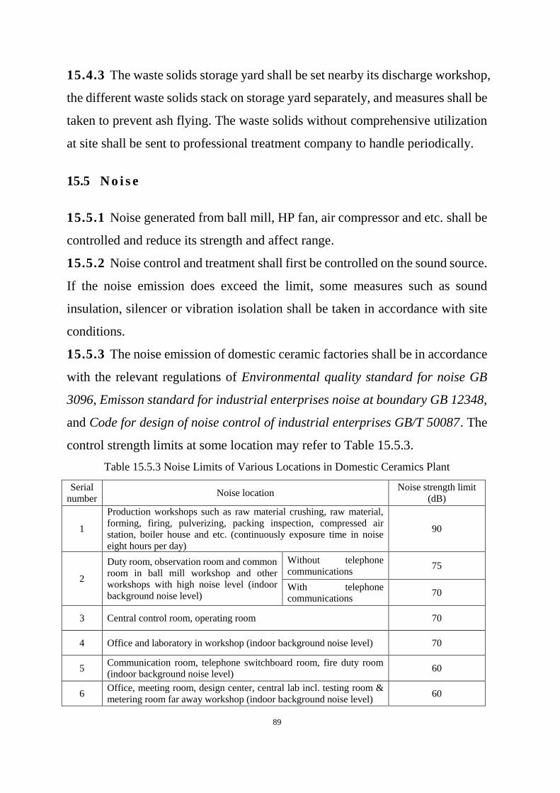
89
15.4.3 The waste solids storage yard shall be set nearby its discharge workshop,
the different waste solids stack on storage yard separately, and measures shall be
taken to prevent ash flying. The waste solids without comprehensive utilization
at site shall be sent to professional treatment company to handle periodically.
15.5 N o i s e
15.5.1 Noise generated from ball mill, HP fan, air compressor and etc. shall be
controlled and reduce its strength and affect range.
15.5.2 Noise control and treatment shall first be controlled on the sound source.
If the noise emission does exceed the limit, some measures such as sound
insulation, silencer or vibration isolation shall be taken in accordance with site
conditions.
15.5.3 The noise emission of domestic ceramic factories shall be in accordance
with the relevant regulations of Environmental quality standard for noise GB
3096, Emisson standard for industrial enterprises noise at boundary GB 12348,
and Code for design of noise control of industrial enterprises GB/T 50087. The
control strength limits at some location may refer to Table 15.5.3.
Table 15.5.3 Noise Limits of Various Locations in Domestic Ceramics Plant
Serial
number Noise location
Noise strength limit
(dB)
1
Production workshops such as raw material crushing, raw material,
forming, firing, pulverizing, packing inspection, compressed air
station, boiler house and etc. (continuously exposure time in noise
eight hours per day)
90
2
Duty room, observation room and common
room in ball mill workshop and other
workshops with high noise level (indoor
background noise level)
Without telephone
communications 75
With telephone
communications 70
3 Central control room, operating room 70
4 Office and laboratory in workshop (indoor background noise level) 70
5 Communication room, telephone switchboard room, fire duty room
(indoor background noise level) 60
6 Office, meeting room, design center, central lab incl. testing room &
metering room far away workshop (indoor background noise level) 60

90
Serial
number Noise location
Noise strength limit
(dB)
7 Medical room, workers’ dormitories (indoor background noise level) 55
91
16 Oc c u pa t io na l Sa fe ty a n d He a l th
16.1 G e n e r a l r u l e s
16.1.1 The design of safety and occupational health facilities for domestic
ceramic factories shall comply with the relevant regulations of the national
standard Hygienic Standards for the Design of Industrial Enterprises GBZ 1.
16.2 F i r i n g a n d e x p l o s i v e p r e v e n t i n g
16.2.1 The fire hazard classification of each workshop shall be determined in
accordance with the requirements in Code of Design on Building Fire Protection
and Prevention GB 50016.
16.2.2 The fire separation distance for workshops, and the arrangement and fire
separation distance of combustible oil (or combustible gas) tanks and their
auxiliary facilities shall meet related requirements of national standard Code of
Design on Building Fire Protection and Prevention GB 50016.
16.2.3 The design of electrical installations shall meet related requirements of
Code for Design of Electrical Installations in Explosive Atmospheres GB 50058.
16.2.4 The design of pressure vessels and pressure piping shall meet related
requirements of Pressure Vessels GB/T 150 and Pressure Piping Code -—
Industrial Piping GB/T 20801.
16.3 P r o t e c t i o n a g a i n s t m e c h a n i c a l i n j u r y
16.3.1 The design and installation of production equipment shall meet related
requirements of Safety of Machinery — Guards — General Requirements for the
Design and Construction of Fixed and Movable Guards GB/T 8196, Hygienic
Standards for the Design of Industrial Enterprises GBZ 1 and General Rules for

92
Designing the Production Facilities in Accordance with Safety and Health
Requirements GB5083.
16.3.2 The safety devices of lifting machinery shall meet related requirements
of Safety Rules for Lifting Appliances GB 6067.1~7.
16.3.3 The construction and installation of electric lifts shall meet related
requirements of Safety Rules for the Construction and Installation of Electric
Lifts GB 7588.
16.3.4 The arrangement of equipment such as machines and workbenches shall
facilitate the safe operation of workers, and the width of passageway around
them shall not be less than 1m.
16.4 L i g h t n i n g P r o t e c t i o n
16.4.1 The lightning protection design of buildings shall be determined
according to the characteristics of geography, geology, meteorology,
environment and lightning activity and the features of protected objects.
16.4.2 The lightning protection classification of auxiliary buildings for
production plants shall be determined by the property of production, possibilities
and consequences of lightning accidents and lightning protection requirements,
and shall meet the requirements of Code for Design Protection of Structure
against Lightning GB 50057.
16.4.3 The lightning protection and grounding measures for buildings shall
meet related requirements of Code for Design Protection of Structure against
Lightning GB 50057.
16.5 P r o t e c t i o n a g a i n s t d u s t a n d t o x i c a n t s
16.5.1 In each production operation space, the maximum allowable
concentration of dust in air and the frequency of ventilation in building shall
comply with related requirements in Chapter 12 of this standard.

93
16.5.2 The design of the protection against dust and toxicants shall meet related
requirements in Chapter 12 of this standard.
16.6 H e a t s t r o k e p r e v e n t i o n , c o o l i n g a n d h e a t i n g
16.6.1 Heatstroke prevention and cooling measures shall meet related
requirements of Hygienic Standards for the Design of Industrial Enterprises
GBZ 1.
16.6.2 The heating and cold-proof design shall meet related requirements in
Chapter 12 HVAC of this standard.
16.7 N o i s e c o n t r o l
16.7.1 The noise control in factory area shall comply with relevant regulations
of Environmental Quality Standard for Noise GB 3096, Emission Standard for
Industrial Enterprise Noise at Boundary GB 1234 and Code for Design of Noise
Control of Industrial Enterprises GB/T 50087.
16.7.2 For production process with high noise such as raw material crushing
and product grinding, mechanized and automated process shall be adopted to
achieve remote operation.
16.7.3 Soundproof rooms may be set in high-noise production sites for control,
supervision and watch. High-noise equipment should be arranged in soundproof
equipment room and be separated from operation area.
16.7.4 Flexible connections shall be used between equipment with strong
vibration. The connection between the pipeline with strong vibration and
buildings, structures or supports shall not adopt rigid connection.
16.7.5 Damping and sound insulation measures shall be taken when
transporting lump materials.
16.7.6 Mufflers shall be installed at the air inlet or outlet for equipment that
generates aerodynamic noise.
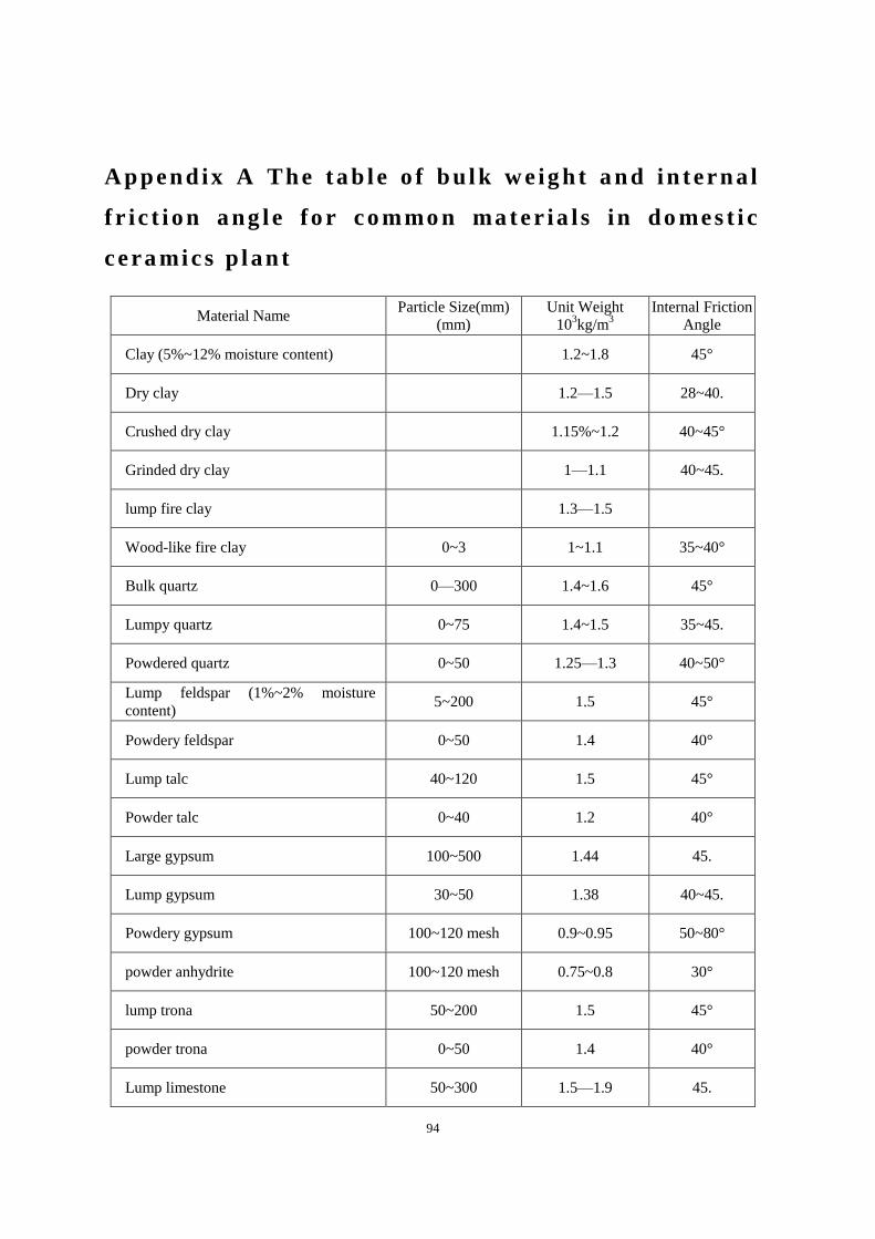
94
A p pe n d ix A Th e ta b l e o f b u l k w e ig h t a n d i n t er n a l
f r i c t i on a ng l e fo r c o mmo n ma te r ia l s i n do me s t i c
c e ra mi c s p l an t
Material Name Particle Size(mm)
(mm)
Unit Weight
103kg/m
3
Internal Friction
Angle
Clay (5%~12% moisture content)
1.2~1.8 45°
Dry clay
1.2—1.5 28~40.
Crushed dry clay
1.15%~1.2 40~45°
Grinded dry clay
1—1.1 40~45.
lump fire clay
1.3—1.5
Wood-like fire clay 0~3 1~1.1 35~40°
Bulk quartz 0—300 1.4~1.6 45°
Lumpy quartz 0~75 1.4~1.5 35~45.
Powdered quartz 0~50 1.25—1.3 40~50°
Lump feldspar (1%~2% moisture
content) 5~200 1.5 45°
Powdery feldspar 0~50 1.4 40°
Lump talc 40~120 1.5 45°
Powder talc 0~40 1.2 40°
Large gypsum 100~500 1.44 45.
Lump gypsum 30~50 1.38 40~45.
Powdery gypsum 100~120 mesh 0.9~0.95 50~80°
powder anhydrite 100~120 mesh 0.75~0.8 30°
lump trona 50~200 1.5 45°
powder trona 0~50 1.4 40°
Lump limestone 50~300 1.5—1.9 45.

95
Material Name Particle Size(mm)
(mm)
Unit Weight
103kg/m
3
Internal Friction
Angle
Powdered limestone 0~50 1.45 40°
lump dolomite 100~300 1.5 45.
Powdered dolomite 0~300 1.4 40°
Waste porcelain tiles
0.8
Waste porcelain powder
1.4 40°
Lump bauxite 50~200 1.6 45.
Powder bauxite 0~50 1.5 40°
Waste saggar chip
1.0
Waste sagger powder
1.2 40°
Recovered stock (8%~14% moisture
content)
0.85
Pebble (grinding body)
1.55 45°

96
Ex p l a na t io n o f t e r ms u se d i n th i s sp e c i f i c a t io n
1.Words used for expressing different degrees of strictness are explained as
follows in order to mark the difference in executing the requirements in this
code:
1) Words denoting a very strict or mandatory requirement:
“must” is used for affirmation and “must not” is used for negation.
2) Words denoting a strict requirement under normal conditions:
“shall” is used for affirmation and “shall not” is used for negation.
3) Words denoting a permission of slight choice or an indication of the
most suitable choice when conditions allow:
“should” or “can” is used for affirmation and “should not” is used
for negation.
4) Expressing choice is permitted, if condition is allowed it is a choice
using the word “may”.
2 “shall comply with...” or “shall meet the requirements of” is used in this
code to indicate that it is necessary to implement other relative standards and
stipulations.
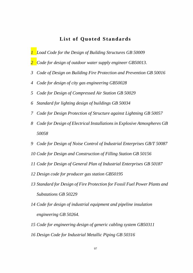
97
Li s t o f Qu o te d S ta n da r ds
1 Load Code for the Design of Building Structures GB 50009
2 Code for design of outdoor water supply engineer GB50013.
3 Code of Design on Building Fire Protection and Prevention GB 50016
4 Code for design of city gas engineering GB50028
5 Code for Design of Compressed Air Station GB 50029
6 Standard for lighting design of buildings GB 50034
7 Code for Design Protection of Structure against Lightning GB 50057
8 Code for Design of Electrical Installations in Explosive Atmospheres GB
50058
9 Code for Design of Noise Control of Industrial Enterprises GB/T 50087
10 Code for Design and Construction of Filling Station GB 50156
11 Code for Design of General Plan of Industrial Enterprises GB 50187
12 Design code for producer gas station GB50195
13 Standard for Design of Fire Protection for Fossil Fuel Power Plants and
Substations GB 50229
14 Code for design of industrial equipment and pipeline insulation
engineering GB 50264.
15 Code for engineering design of generic cabling system GB50311
16 Design Code for Industrial Metallic Piping GB 50316
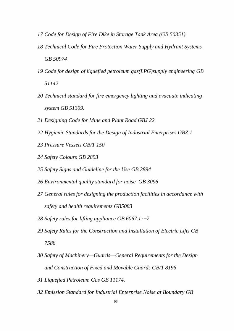
98
17 Code for Design of Fire Dike in Storage Tank Area (GB 50351).
18 Technical Code for Fire Protection Water Supply and Hydrant Systems
GB 50974
19 Code for design of liquefied petroleum gas(LPG)supply engineering GB
51142
20 Technical standard for fire emergency lighting and evacuate indicating
system GB 51309.
21 Designing Code for Mine and Plant Road GBJ 22
22 Hygienic Standards for the Design of Industrial Enterprises GBZ 1
23 Pressure Vessels GB/T 150
24 Safety Colours GB 2893
25 Safety Signs and Guideline for the Use GB 2894
26 Environmental quality standard for noise GB 3096
27 General rules for designing the production facilities in accordance with
safety and health requirements GB5083
28 Safety rules for lifting appliance GB 6067.1~7
29 Safety Rules for the Construction and Installation of Electric Lifts GB
7588
30 Safety of Machinery—Guards—General Requirements for the Design
and Construction of Fixed and Movable Guards GB/T 8196
31 Liquefied Petroleum Gas GB 11174.
32 Emission Standard for Industrial Enterprise Noise at Boundary GB

99
12348
33 Pipe Supports and Hangers GB/T 17116.1~3
34 Natural Gas GB 17820
35 Pressure Piping Code—Industrial Piping GB/T 20801
36 Measurement and Calculation Method of Heat Balance and Thermal
Efficiency for Ceramic Industrial Kiln GB/T 23459
37 The Norm of Energy Consumption Per Unit Products of Domestic
Ceramics GB 36890
38 Technical standard for polyethylene (PE) gaseous fuel pipeline
engineering (CJJ 6
39 Metal Valves for Gas Transmission (CJ/T 514).
40 High bay welded steel rack ---- Specicfications JB/T 5323.
41 Automated storage and retrieval system-Design rules JB/T 9018
42 Automated storage and retrieval system-General rules JB/T 10822
43 Code for Construction and Acceptance of Chemical Equipment and
Pipeline Anticorrosive Engineering HG/T 20229
44 Design Code for External Corrosion Protection of Chemical Equipment
and Piping HG/T 20679
45 Design Specification for Anticorrosion Coating of Equipment and Piping
in Petrochemical Engineering SH/T 3022
46 Design specification for automated high-bay warehouse in
petrochemical industry SH/T 3186

100
47 Pressure Pipe Safety Technology Supervision Regulation for Industrial
Pressure Pipe TSG D0001

101
Indust ry Standards of the People ' s Republ ic
of China
Code for design of Domestic
Ceramics Plant
Q B / T 6 0 1 7—2 0 X X
Explana t ion of Provis ions

102
R ev is io n N o te s
Code for design of domestic ceramics plant QB/T 6017-202X is approved
and published as in Announcement of publishing numberd XX, on XX day, XX
month of 202XX by the Ministry of Industry and Information Technology.
In the process of revising this code, the development department
conducted extensive solicitation of opinions and investigations, and carefully
summarized the practical experience of engineering construction design and
consulting in China. At the same time, it referred to foreign advanced technical
regulations and technical standards, as well as the original Code for design of
domestic ceramics plant QB/T 6017-1997.
Compared with the 1997 Code, following content is revised and modified
in Code for design of domestic ceramics plant QB/T 6017-202X:
1. “Chapter 2 Terms and symbols”, “Chapter 14 Energy saving” and
“Chapter 16 Occupational safety and health” are added.
2. The original “Chapter2 General layout” is revised as “Chapter3
Location selection and general layout”. Location selection related
content is added.
3. China, as a major manufacturing country in the world, has a very
perfect industrial manufacturing system. At present, the social division
of labor is more and more refined and the external coordination and
supporting service are very complete. The repqir and maintenance
work of newly-built industrial projects are all implemented by
103
socialized services.Therefore, Article 8 “Maintennance Workshop” of
Chapter 3 in the original code is deleted.
4. The provisions of original “Chapter 5 Fuel” has been substantially
deleted, and the provisions on clean fuel such as natural gas have been
added.
5. The original Chapter “Water supply and drainage and Fir fighting” is
split into two two chapters, namerly “Chapter 11 Water supply and
drainage” and “Chapter13 Fire fighting”.
6. The content of calculation of tunnel kiln lengthis deleted.
7. Article 4.7 Packaging and warehousing workshop and related
provisions have been added to “Chapter 4 Process”.
8. Contents that are not suitable for technological progress are modified
and adjusted.
9. In accordance with the relevant regulations and requirements in the
Provisions for the Compilation of Engineering Construction
Specifications, some of the provisions in the original code have been
modified and adjusted in writing.
Chief development department of 1997 Code: Changsha Design Institute
of China National Council of Light Industry (Former name of China CEC
Engienering Corporation)
Main drafting staff of 1997 Code: Huang Binggang, Zhang Fujun, Weng
Xinfan, Shi Weizhi, Wu Ming, Ning Chengwa, Xue Ruiyuan, Pan Kailing, Zhou

104
Erhui, Li Xiangzhou, Peng Shipin, Yang Zehong, Pan Ruizhen and Dong
Guangwu.
In the process of this revision, some of the main drafters of the 1997 Code,
such as Wu Ming, Ning Chengwa, Peng Shiliang, etc., acted as consultants for
this revision. They have put forward with pertinent comments and suggestions
on the revision principles, guidelines, and the technical regulations of specific
provisions in this revision.
For the purpose of facilitating the design, construction, scientific research,
schools and other entities to correctly understand and implement the provisions
of the Code when using the Code, the articles explanation of the Code has been
compiled in the order of chapters, sections and articles, and the purpose and
basis of the provisions of the Code as well as relevant matters needing attention
in the course of implementing the Code are explained. However, the
descriptions of the provisions of this clause do not have the same legal effect as
the standard text, which is only for the user to understand and grasp the standard
provisions.

105
Ta bl e o f Co n te n ts
1 G e n e r a l P r o v i s i o n s . . . . . . . . . . . . . . . . . . . . . . . . . . . . . . . . . . . . . . . . . . . . . . . . . . 1
3 L o c a t i o n s e l e c t i o n a n d g e n e r a l l a yo u t . . . . . . . . . . . . . . . . . . . . . . . . 1
3 . 2 G e n e r a l l a y o u t . . . . . . . . . . . . . . . . . . . . . . . . . . . . . . . . . . . . . . . . . . . . . . . . . . . . 1
3 . 3 B u i l d i n g . . . . . . . . . . . . . . . . . . . . . . . . . . . . . . . . . . . . . . . . . . . . . . . . . . . . . . . . . . . . . 3
3 . 4 P a s s a g e s a n d r o a d s . . . . . . . . . . . . . . . . . . . . . . . . . . . . . . . . . . . . . . . . . . . . . . 4
3 . 5 T e c h n i c a l a n d e c o n o m i c i n d i c a t o r s . . . . . . . . . . . . . . . . . . . . . . . . 5
4 P r o c e s s . . . . . . . . . . . . . . . . . . . . . . . . . . . . . . . . . . . . . . . . . . . . . . . . . . . . . . . . . . . . . . . . . . 5
4 . 1 G e n e r a l p r o v i s i o n s . . . . . . . . . . . . . . . . . . . . . . . . . . . . . . . . . . . . . . . . . . . . . . 5
4 . 2 R a w m a t e r i a l w o r k s h o p . . . . . . . . . . . . . . . . . . . . . . . . . . . . . . . . . . . . . . . . 6
4 . 3 F o r m i n g w o r k s h o p . . . . . . . . . . . . . . . . . . . . . . . . . . . . . . . . . . . . . . . . . . . . . . . 8
4 . 4 F i r i n g w o r k s h o p . . . . . . . . . . . . . . . . . . . . . . . . . . . . . . . . . . . . . . . . . . . . . . . . . . 9
4 . 5 D e c o r a t i n g f i r i n g w o r k s h o p . . . . . . . . . . . . . . . . . . . . . . . . . . . . . . . . . 1 0
4 . 6 P l a s t e r m o u l d i n g w o r k s h o p . . . . . . . . . . . . . . . . . . . . . . . . . . . . . . . . . 1 1
4.7 Packaging warehousing worshop . . . . . . . . . . . . . . . . . . . . . . . . . . . . . . . . . . . . 1 2
4.8 Process piping . . . . . . . . . . . . . . . . . . . . . . . . . . . . . . . . . . . . . . . . . . . . . . . . . . . . . . . 1 3
4.9 Central laboratory and R&D center . . . . . . . . . . . . . . . . . . . . . . . . . . . . . . . . . . 1 4
5 K i l n . . . . . . . . . . . . . . . . . . . . . . . . . . . . . . . . . . . . . . . . . . . . . . . . . . . . . . . . . . . . . . . . . . . . 1 4
5 . 1 G e n e r a l p r o v i s i o n s . . . . . . . . . . . . . . . . . . . . . . . . . . . . . . . . . . . . . . . . . . . . 1 4
5 . 2 D e t e r m i n a t i o n o f k i l n t y p e . . . . . . . . . . . . . . . . . . . . . . . . . . . . . . . . . 1 5
5 . 3 D e t e r m i n a t i o n o f m a i n t e c h n i c a l a n d e c o n o m i c i n d e x
1 5
106
6 F u e l . . . . . . . . . . . . . . . . . . . . . . . . . . . . . . . . . . . . . . . . . . . . . . . . . . . . . . . . . . . . . . . . . . . . 1 6
6 . 1 G e n e r a l p r o v i s i o n s . . . . . . . . . . . . . . . . . . . . . . . . . . . . . . . . . . . . . . . . . . . . 1 6
6 . 2 F u e l g a s . . . . . . . . . . . . . . . . . . . . . . . . . . . . . . . . . . . . . . . . . . . . . . . . . . . . . . . . . . . 1 7
6 . 3 F u e l o i l . . . . . . . . . . . . . . . . . . . . . . . . . . . . . . . . . . . . . . . . . . . . . . . . . . . . . . . . . . . . 1 8
8 P o w e r s u p p l y . . . . . . . . . . . . . . . . . . . . . . . . . . . . . . . . . . . . . . . . . . . . . . . . . . . . . . . . 1 9
9 A u t o m a t i c c o n t r o l i n s t r u m e n t a n d i n f o r m a t i o n . . . . . . . . . . 2 1
1 0 B u i l d i n g s t r u c t u r e . . . . . . . . . . . . . . . . . . . . . . . . . . . . . . . . . . . . . . . . . . . . . 2 2
1 0 . 1 B u i l d i n g . . . . . . . . . . . . . . . . . . . . . . . . . . . . . . . . . . . . . . . . . . . . . . . . . . . . . . . . . . . 2 2
1 0 . 2 S t r u c t u r e . . . . . . . . . . . . . . . . . . . . . . . . . . . . . . . . . . . . . . . . . . . . . . . . . . . . . . . . . . 2 3
1 1 W a t e r s u p p l y a n d d r a i n a g e . . . . . . . . . . . . . . . . . . . . . . . . . . . . . . . . . 2 4
1 2 H e a t i n g v e n t i l a t i o n a n d a i r c o n d i t i o n i n g . . . . . . . . . . . . . . 2 4
1 4 E n e r g y s a v i n g . . . . . . . . . . . . . . . . . . . . . . . . . . . . . . . . . . . . . . . . . . . . . . . . . . . 3 2
1 4 . 1 G e n e r a l p r o v i s i o n s . . . . . . . . . . . . . . . . . . . . . . . . . . . . . . . . . . . . . . . . . . . . 3 2
1 4 . 2 P r o c e s s e n e r g y s a v i n g . . . . . . . . . . . . . . . . . . . . . . . . . . . . . . . . . . . . . . . . 3 2
1 4 . 3 W a s t e h e a t r e c o v e r y a n d u t i l i z a t i o n . . . . . . . . . . . . . . . . . . . . . 3 5
1 4 . 4 P o w e r s a v i n g . . . . . . . . . . . . . . . . . . . . . . . . . . . . . . . . . . . . . . . . . . . . . . . . . . . . 3 5
1 5 E n v i r o n m e n t a l p r o t e c t i o n . . . . . . . . . . . . . . . . . . . . . . . . . . . . . . . . . . . 3 6
1 5 . 1 G e n e r a l p r o v i s i o n s . . . . . . . . . . . . . . . . . . . . . . . . . . . . . . . . . . . . . . . . . . . . 3 6
1 5 . 2 W a s t e w a t e r . . . . . . . . . . . . . . . . . . . . . . . . . . . . . . . . . . . . . . . . . . . . . . . . . . . . . . 3 7
1 5 . 3 W a s t e g a s . . . . . . . . . . . . . . . . . . . . . . . . . . . . . . . . . . . . . . . . . . . . . . . . . . . . . . . . . 3 7
1 5 . 4 W a s t e s o l i d s . . . . . . . . . . . . . . . . . . . . . . . . . . . . . . . . . . . . . . . . . . . . . . . . . . . . . 3 8
1 5 . 5 N o i s e . . . . . . . . . . . . . . . . . . . . . . . . . . . . . . . . . . . . . . . . . . . . . . . . . . . . . . . . . . . . . . . 3 8

107
1 6 O c c u p a t i o n a l s a f e t y a n d h e a l t h . . . . . . . . . . . . . . . . . . . . . . . . . . . 3 8
1 6 . 1 G e n e r a l p r o v i s i o n s . . . . . . . . . . . . . . . . . . . . . . . . . . . . . . . . . . . . . . . . . . . . 3 9
1 6 . 4 L i g h t n i n g p r o t e c t i o n . . . . . . . . . . . . . . . . . . . . . . . . . . . . . . . . . . . . . . . . . . 3 9
1 6 . 7 N o i s e c o n t r o l . . . . . . . . . . . . . . . . . . . . . . . . . . . . . . . . . . . . . . . . . . . . . . . . . . . . 3 9

1
1 General Provisions
1.0.1 Define the purpose of this specification.
1.0.2 Desfine the applicable scope of this code. Cancel the requirement on
project construction scale, which has been included in the national mandatory
standard Code for Commodity Engineering Project.
1.0.3 Define the principle of adapting new process, new technologies, new
materials and new equipment in the design of domestic ceramic plants.
1.0.4 Define the specific standard for energy consumption per unit of product.
3 Location selection and general layout
3.2 General layout
3.2.1 Optimal land utilization is China’s basic national policy. This provision
emphasize that the general layout design of industrial enterprises must pay special
attention to saving land, rationally using land and improving the utilization of
land.
3.2.11 This provision is the general principle of vertical design. The vertical
design and plane position shall be closely connected, considered together and
coordinated with each other to make the entire project practical, economical and
aesthetic.
The design elevation of site shall coordinate with the outside transportation
route, drainage system and the elevation of surrounding site, otherwise there will
problems such as railway connection failure, excessive road slope, poor drainage
and high retaining wall.
3.2.12 There are many production processes for domestic ceramics. Pallet trucks,
flatbed trucks, forklifts and other transportation tools are often used for
transportion between processes. In order to ensure smooth connection between
2
processes and guarantee product quality, production plants prefer to adopt
combined workshops. When terrain conditions permit, flat slope type of general
layout is selected, which is easier to meet process requirements.
3.2.14 As an integral part of the general layout design of industrial enterprises,
comprehensive pipeline arrangement is one of the standards to measure the
reasonability of plane layout. It involves a wide range of disciplines, such as
process, water, electrical, thermal and HVAC. The comprehensive pipeline
arrangement connects the economic feasibility of the pipeline layout for each
discipline with the overall situation of the enterprise to achieve the overall
economic rationality of the enterprise.
The comprehensive pipeline of industrial enterprises almost covers the
whole plant area. Arranging the pipelines in a comprehensive, reasonable and
compact way may facilitate construction, maintenance and safety production, as
well as save land and reduce investment.
3.2.15 Parallel arrangement of pipeline, roads and building axes is an effective
way for optimal land utilization, and may also facilitate pipeline maintenance and
laying of new pipelines in the future. Arranging main pipe near the side with
higher demand is for the purpose of reducing intersection with roads and other
pipelines and shortening the length of branch pipes. The minimum horizontal
distance between the pipelines and the buildings, structure and roads shall meet
the requirements of Code for Design of General Plan of Industrial Enterprises
GB 50187.
3.2.16 The pipelines may be set above ground or underground. The pipelines
mentioned in the provisions generally refer to fuel oil, liquefied petroleum gas,
producer gas, town gas and natural gas pipelines. On account that pipeline leakage
is inevitable during long-term operation, overhead installation is adopted for
easier discovery and more convenient maintenance when leakage occurs. If the
underground pipe trench type is used, leakage cannot be easily found. Once
exposed to the ground, the accident is no longer at the initial stage and already
3
harmful. Therefore, for these pipeline, installation with pipe racks is the best way
for the sake of safety and maintenance. The minimum horizontal distance
between pipes racks and buildings and structures and the minimum vertical
distance across railways and roads shall meet the requirements of the current
Code for Design of General Plan of Industrial Enterprises GB 50187.
3.2.17 This chapter only mentions the special requirements for the general
layout design of domestic ceramic plants. Other professional requirements on
general layout design shall follow the current national standard Code for Design
of General Plan of Industrial Enterprises GB 50187.
3.3 Building
3.3.1 The layout of the main production workshop should meet the
requirements:
1 On account that the pollution of ceramic raw materials, especially the
pollution of iron dust and coal dust, will affect the quality of product directly,
bringing defects to the surface of finished product and lowering product grade,
it is proposed that the raw material workshop shall be arranged “away from
pollution sources that may affect production quality, such as coal yard,
maintenance workshop and gypsum model workshop”.
2 According to the requirements in Code of Design on Building Fire
Protection and Prevention GB 50016 (2018 Edition), raw material workshop
belongs to Category E production, while Forming workshop and Firing
workshop belong to Category D production. When the fire resistance class of
factory building is Class I or II, the maximum permitted area for total
compartment is not limited. According to the fire protection and prevention
code, these three workshops may be set together. Therefore, it is clear that the
Forming workshop should be close to or form a joint building with raw
material workshop and Firing workshop.

4
3 The length of Firing workshop building is relatively long, generally
96~120m. If the natural terrain of the plant has a large slope, the workshop
shall be arranged along the contour line to reduce the quantity of earthwork.
Setting the foundation of tunnel kiln on the terrain elevation of little change
may also reduce uneven settlement.
The Firing workshop has a high-temperature production condition, with heat
dissipation capacity of 304×104 kJ/h. Generally skylights are used for thermal
discharge. The angle between the workshop orientation and the maximum
frequency summer wind direction should be 60°~90° and should not be less than
45°. In order to reduce the influence of heat emitted by tunnel kilns, kiln cars and
products on nearby operators, the Firing workshop should be arranged on the
leeward side of the maximum frequency summer wind direction in Forming
workshop. When joint building is adopted, the Firing workshop and Forming
workshop should be separated by patio.
3.4 Passages and roads
3.4.1 The width of passageway in the factory area is mainly determined
according to various functional requirements, with due consideration to the
aesthetic needs. Based on the past engineering design experience, six
requirements on passageway are put forward as factors that shall be met when
determining the width of passageway.
Currently, there are two ways to divide the width of passageway in factory area,
one is by plant area and the other is by production scale. Considering that the
combinations of production buildings in domestic ceramic plants of the same scale
are diverse (such as single-layer and multi-layer, combined and dispersed) due to the
differences in the types and sources of fuel employed for firing, there is a huge
discrepancy in plant area, therefore deciding the width of passageway by plant area
classification is more in line with the production practice of domestic ceramic plant.
5
3.4.2 The appearance of a factory represents the image of an enterprise. In
practice, most enterprises prefer straight roads and square partitions. Roads should
be parallel to the axis of main building and avoid corners, which may facilitate the
arrangement of piping engineering to be a ring shape to realize smooth material
transportation, make the production process more reasonable and contribute to
fire protection.
3.5 Technical and economic indicators
3.5.2 The building coefficient of domestic ceramic plants is approximately
31.7%~44.12%. Considering that the coefficient is influenced by many factors,
such as the terrain and the size of the joint building, it is difficult to determine its
rationality with an average figure. Therefore the building coefficient should be
32%~42%.
4 Process
4.1 General provisions
4.1.1 Process design covers raw materials, forming, firing, decorating firing,
plaster modeling, etc. According to the development plan of domestic ceramic
industry, auxiliary materials shall realize specialized production. In practice, on
account that high-quality kiln furniture and gypsum power commodities are
available in market, there is no need for new plants to consider this part of project.
Therefore, sagger (kiln furniture) production and gypsum power frying are not
included in this code.
During the construction drawing design stage, if there are major changes
to the approved preliminary design, such as the changes in plant location,
6
production scale, fuel structure, main process equipment and building
structure, the permission from the original examination and approval
authority must be obtained.
4.2 Raw material workshop
This section applies to raw material workshops employing powdered hard
raw materials and refined soft raw materials or directly using raw ore.
With the development of the domestic ceramic industry, the raw materials
for ceramic production are developing in the direction of specialized
production. At present, various ceramic production areas and mining areas
starts to develop a processing and supply system for hard raw materials;
specialized production of soft raw materials such as kaolin is under planning
and development, and a small amount of refined raw materials may be
produced and supplied. Therefore, in engineering design, hard powders
processed by specialized manufacturers are generally used, and there is no
crushing system for hard raw materials in the workshop; where conditions
permit, refined soft raw materials are used, or raw ore is directly used in the
workshop. There is no panning system.
The process design of raw material workshops should cover the following
scope: starting from the entry of raw materials into workshop, passing through
necessary production processes such as selection, storage, dosing, ball milling,
sieving, de-ironing, filter pressing, ageing and pugging, till delivering the pug
and glaze slip to the Forming workshop.
4.2.2 Process design requirements
1 Quality requirements on raw materials. For those already listed in
national or industry standards, corresponding national or industry standards
shall be followed, and for those not covered, reference may be made to
relevant group standards or corporate standards, and the content of harmful

7
substances shall be strictly controlled in accordance with the requirements of
different ceramic products.
2 At present, the kaolin raw materials used in domestic ceramic plants
in China are generally bulk kaolin ore, which may be easily mixed with
impurities in the process of exploitation, transportation and storage. Therefore,
the raw materials shall be selected to remove impurities upon arrival at
workshop. Selected kaolin raw materials are packed in bags and may be used
directly.
3 Basic requirements and principles of raw material storage shall be
applied flexibly in design, with due considerations to specific conditions of
each plant. For example, some raw materials should be weathered, so there
shall be a certain weathering period.
4.2.3 Among the main process design indicators, the loss rate of raw material
storage, transportation and pulping is determined with reference to the values
specified in Code for Design of Building and Sanitary Ceramic Plant
GB5060-2010.
According to Table 8.1.4-1 “Raw Material Loss Rate in Each Production
Section of Ceramic Tile Production Line” and Table 8.1.4-2 “Raw Material
Loss Rate in Each Production Section of Ceramic Sanitary Ware Production
Line” of Code for Design of Building and Sanitary Ceramic Plant
GB5060-2010, the loss rates of various ceramic materials in storage and
transportation (2%), ball milling and pulping (2%) and powdering (2%)
section are basically the same, much lower than the loss rate (no greater than
10%) of kaolin and clay ore and close to the loss rate (5%) of refined materials.
Therefore, the loss rate data in the original 1997 Code is revised to be
consistent with the Code for Design of Building and Sanitary Ceramic Plant.
According to Table 8.1.8 “Maximum Fuel Consumption Value of Per
Unit Product of Main Heat-consuming Equipment” of Code for Design of
Building and Sanitary Ceramic Plant GB5060-2010 and relevant energy

8
consumption data about spray drying powdering in Table 5.2.3 “Design
Quota of Energy Consumption for Main Production Processes of Dry-pressed
Ceramic Tile Production Line” in Standard for Design of Energy
Conservation of Building and Sanitary Ceramic Plant GBT50543-2019, the
energy value consumed by per kg of water is about 3094kJ, much lower than
the 4390kJ/kg in the original 1997 Code. It is recommended to make proper
amendments.
4.2.4 Main equipment selection
1 When the ball mill adopts electric hoist for feeding, standby shall be
considered. If large-tonnage ball mill employs belt conveyor for feeding,
standby is not necessary.
2 According to the actual use of filter press mud conveying pump at
home and abroad, using plunger mud pump to transport mud press filter may
improve the efficiency of press filter and reduce the moisture content of mud
cake.
3 Three-shaft stainless steel vacuum pug mill is selected to improve the
quality of mug.
4.2.5 Process layout of workshop
2 Handling the relationship between the equipment foundation, pit and
trench, wall and column foundation means that the design shall give
considerations to factors such as mutual interference, foundation forces,
foundation settlement and vibration during construction and use.
4.3 Forming workshop
4.3.1 The design of Forming workshop should include processes such as
forming, demoulding, drying, trimming, glazing, inspection and storage.
Forming may be divided into plastic forming, isostatic compaction forming,
casting forming, 3D printing forming, etc. In design or actual production,

9
plastic forming and isostatic compaction forming may be combined into
one section. In project with more casting products, casting forming may be
separated as an independent workshop.
Proper shaping process is essential for reducing product pollution, improving
product quality and cutting down energy consumption.
4.3.2 Process design requirements
Types 1 to 3 are specific design measures to improve product quality.
4.3.3 The main process design indicators are production and design experience
data, which may be used in process design calculations.
4.3.4 Generally standby for equipment in Forming workshop is not necessary.
But for the selection of forming equipment, the possibility of replacing product to
adapt to market changes shall be considered.
4.3.5 Equipment layout of workshop
5 According to equipment installation, production and design
experience.
6 Same as the description in paragraph 2 of Article 4.2.5.
4.4 Firing workshop
4.4.2 Process design requirements
1 In the double firing production process, generally hard porcelain
adopts low-temperature biscuit firing and high-temperature glaze firing
processes while soft porcelain employs high-temperature biscuit firing and
low-temperature glaze firing process.
4.4.4 Article 4.4.4 is the principle of process equipment selection, which should
be used flexibly in design according to the actual situation of plant, especially for
the selection of kiln type.

10
4.4.5 Article 4.4.5 is the basic principle of equipment layout in Firing workshop,
which should be used flexibly in design according to the specific conditions of
each plant.
4.5 Decorating firingworkshop
This section is applicable to the over-glaze decorating and Firing workshop.
Glaze decoration is generally divided into over-glaze, in-glaze and underglaze.
The process of these three decoration methods is different, but the
requirement for process design is basically the same. Therefore, in-glaze and
other decoration methods may refer to the provisions of this section.
The process design scope in decoration workshop should include: from the
beginning when white porcelain gets into workshop, through decorating,
firing, grading, assembling, packaging, to the storage of finished products.
4.5.2 Process design requirements
1 Due to the different nature of decal, liquid gold and pigment, the
requirement for storage environment varies. Meanwhile, the process of
warehousing and picking may lead to mutual contamination, resulting in
“diphtheria infection” and loss of materials. To facilitate management and
meet the environment requirement of various materials, they shall be stored in
separate rooms.
3 In the heating area, when the white ceramic warehouse has no
heating facilities, the white ceramics shall be stored in the color baking
workshop for at least two days to avoid decorating on cold porcelain.
Decorated products shall be fired in the kiln the same day to avoid pollution.
The pasted products shall be baked in the kiln every day to avoid storage
pollution. Plastic boxes or wooden boxes for storing products shall be of
uniform size to facilitate stacking and save storage space.

11
4.5.3 Main process design index is production and design experience data,
which may be used in process design calculation. When used in practice, it shall
be adjusted according to the characteristics of the product (such as the shape of
decoration, gold ratio, etc)
4.5.4 The fuel of decorating firing kiln is generally the same as that of the
calcining kiln. If the power supply permits, it may also use electric kiln.
Continuous bogie kiln is also widely used.
4.6 Plaster moulding workshop
This section is applicable to the process design of Plaster moulding
workshop with α or β type hemihydrate plaster powder as casting material.
Domestic ceramic plants currently use α or β type hemihydrate plaster
powder as moulding material, while artificial plaster and chemical plaster is
also internationally used. Isostatic compaction soft film, microporous resin
mould formed by high pressure slip casting, and other moulding materials
may be used to increase use times. Plaster powder is supplied by professional
production plant or market.
Plaster moulding workshop may include process of plaster powder
storage, prototype, master molds, moulding preparation, moulding drying and
moulding trimming.
4.6.1 Process design shall meet the following requirements:
2 During the preparation of calcium plaster, a plaster vacuum
deaeration mixer is used to perform vacuum deaeration and stirring of calcium
plaster, which may reduce the bubbles in the plaster casting and improve its
strength.
3 Because of its slow dehydration and long drying characteristic, the
plaster moulding generally uses chamber type drying room.
12
4 The Plaster moulding workshop should be placed near the Forming
workshop or in the same plant with the Forming workshop to avoid
long-distance transportation of castings. When it is arranged in the same
factory building as the Forming workshop, the model preparation and forming
section shall be separated by a wall to prevent gypsum from polluting the
production of the Forming workshop.
5 It shall be avoided that plaster powder contaminates raw materials or
semi-finished products, which causes spots or molten holes in the finished
products. The storage place of the plaster powder shall be protected from
moisture to prevent the plaster powder from losing its efficacy due to moisture
absorption.
4.6.2 The main process design indicators are determined based on production
and design experience and may be used in process design calculations.
4.7 Packaging warehousing worshop
4.7.1 During the firing process of ceramic body, various defects may appear,
such as porosity, deformation, crack, and defects that affect the appearance
and beauty of the product but do not affect the use. Before packaging,
defective products and unqualified products shall be removed to ensure
product quality. Generally, the inspection and selection of products is mainly
done manually, and machine scanning identification technology may also be
used to complete manual inspection and selection operation.
4.7.3Ceramic products are fragile and shall be packaged with protective and
economical materials. At present, ceramic products are mainly packed in
cartons. For ceramic products of different shapes, the internal protection
materials are usually paper products, and plastic bubble materials may also be
used for protection.
13
4.7.5The use of high rack three-dimensional warehouses to store products is
the development trend, which is conductive to realize automation and
intelligence. Therefore, as conditions permit, it is recommended to use
automatic warehouse storage.
4.8 Process piping
4.8.2 Define the basic requirements of pipeline engineering design.
4.8.3 It is determined according to the actual usage in domestic ceramic plant.
According to the requirements of pressure use, engineering plastics should not be
used in the pipeline from mud pump to filter press.
4.8.4 Selection of pipe specifications
1 According to the pipe specifications widely used in domestic project
construction and combined with pipe specifications internationally used, it is
recommended to use pipes with domestically preferred specification in this
Code. For other requirements in projects, it may also use pipes with domestic
common specifications.
2 The pipeline connection may adopt the following methods:
1) Welding: It is generally used on pipelines with a design working
pressure above 1.0MPa and a pipe diameter greater than 50mm. Use socket
welding when the pipe is made of engineering plastics.
2) Thread connection: It may only be used on pipelines with a design
working pressure of 1.0MPa or less and a pipe diameter of less than 50mm;
3) Flange connection: It is generally applicable to the material
pipeline with large diameter, low sealing requirement and frequent cleaning,
as well as the connection between pipeline and valve body or equipment.
Different types of flange should be selected according to the pressure and
temperature of pipeline medium;

14
4) Adaptor union: It is applicable to the material pipeline, equipment
connecting pipe and ring connecting pipe which are often dismantled and
cleaned to facilitate maintenance and installation.
4.8.6 The net height of pipeline crossing pedestrian passage is 1.8, 2.0, 2.5 m,
etc., which is not less than 2.2 m in this code.
4.9 Central laboratory and R&D center
4.9.2 Product testing is based on product technical standards, enterprise internal
control standards, national standards and foreign standards for reference.
4.9.3 Instrument and equipment configuration of the central laboratory
2 The instruments and equipment of the central laboratory are closely
related to the characteristics of the products. If it is in-glaze or under-glaze
decoration, there is no need to determine the amount of lead and cadmium
dissolved.
4 Common instruments, including precision balance, thermal
equipment, etc, should be planned and set uniformly.
4.9.4 The R&D center is responsible for the testing of new materials, new
products, new processes, new models, new patterns, as well as the
improvement and research of process technology. The R&D center may set up
a design room to be responsible for product modeling design or pattern design,
and develop new varieties .
5 Kiln
5.1 General provisions
5.1.1 Kiln selection is formulated in accordance with the national energy policy
and the actual situation of domestic ceramic tunnel kiln. According to the
"Thirteenth Five-Year Plan for Energy Conservation and Emission Reduction"
15
issued by the State Council, the "Guidance on Promoting Electricity Substitution
(NDRC Energy Bureau [2016] No.1054)" issued by the National Development
and Reform Commission, and industry technology policy industry plan, this code
does not recommend to employ tunnel kilns, and therefore shortens the contents
of tunnel kilns.
5.1.2 Clean gas refers to natural gas, liquefied petroleum gas, producer gas, etc.
5.1.3 It depends on the fuel used in new kilns with low energy consumption and
high product quality that have emerged in my country in recent years.
5.1.4 Energy saving is an important part in kiln design and an important
technical and also an economic indicator for evaluating kiln design level.
5.2 Determination of kiln type
5.3.3 Among the existing domestic ceramic kilns, old intermittent kilns such as
coal-burning down-flame kilns have been eliminated, and the kilns are
developing in the direction of energy saving, light weight and rapid development.
In recent years, among domestic ceramics firing kilns, new intermittent
kilns such as shuttle kilns and continuous kilns such as high-temperature
roller kilns have developed rapidly. The kilns use light insulation materials,
and products may be made in open-flame firing without saggers. Kilns may be
according to specific process requirements in design.
5.3 Determination of main technical and economic index
5.3.3 Kiln is the most critical thermal equipment for ceramic enterprises and the
equipment with the largest energy consumption. Its energy consumption accounts
for 60% to 80% of the total energy consumption of ceramic production. The
energy consumption of the kiln mainly depends on the structure of the kiln and the
firing technology. The structure of the kiln is the fundamental factor and the firing
technology is the guarantee. In recent years, with the optimization of the furnace
16
structure, the thermal efficiency of the furnace has been greatly improved. For
example, Stone Group Ceramics Co., Ltd. replaced the original kiln with an
optimized structure, increasing the thermal efficiency of the kiln from 19.01% to
40.65%; Chaozhou Xingye Ceramics Co., Ltd. adopted an optimized structure of
roller kiln and adopted daily use With the rapid low-temperature reduction firing
technology of porcelain, the thermal efficiency of the kiln reaches 68.8%.
Therefore, this standard determines that the firing heat efficiency of the kiln is not
less than 40%, which is feasible.
6 Fuel
6.1 General provisions
6.1.2 The relevant national and industry standards, norms and regulations are
mainly listed as follows:
1 Design code for producer gas station GB50195
2 Code for design of city gas engineering GB50028
3 Code for design of oil depot GB 50074
4 Code for design and construction of filling station GB 50156
5 Safety Code for Gas of Industrial Enterprises GB 6222
6 Code for fire protection design of buildings (2018 Edition) GB 50016-
2014
7 Emission standard of pollutants for ceramics industry GB 25464
8 Emission Standard of Air Pollutants for Industrial Kiln and Furnace
GB 9078
9 Hygienic Standards for the Design of Industrial Enterprises GBZ 1
10 Code for electric insllations in explosive atmosphere GB 50058.
6.1.3 The design of gas stations, LPG vaporization stations and oil depots
involves many specialties. In addition to the listed codes, other professional
standard and national or industry standards and regulations should also be
17
followed. For example, the current codes such as Code for fire protection design
of buildings (2018 Edition) GB 50016- 2014, Emission standard of pollutants for
ceramics industry GB 25464, Emission standard of air pollutants for industrial
kiln and furnace GB9078 , Hygienic Standards for the Design of Industrial Enter
GBZ 1-2010, Code for design of electrica iinstallations in explosive atmospheres
GB 50058-2014, etc.
6.2 Fuel gas
Fuel gas in this code mainly refers to natural gas (including pipeline
natural gas, liquefied petroleum gas and compressed natural gas), liquefied
petroleum gas, and coal gas. City gas is not limited a specific kind of gas, and
it may be any of the above-mentioned gases, so it is not listed separately. With
the popularization and application of coal gasification technology in China,
dimethylether (DME), which has developed rapidly in recent years, has good
energy-saving effects as a clean energy with good combustion performance
and thermal efficiency.
6.2.1 Natural gas is a currently widely used clean energy. This section is
added as a compulsive requirement that must be met when using natural gas in
domestic ceramic projects. Others requirements shall be implemented in
accordance with current national regulations.
The hydrogen sulfide content of natural gas shal be less than
20mg/Nm3which is determined in accordance with the technical indicators of
Class II gas in the Natural Gas GB17820.
6.2.2 Desfines the quality requirements of liquefied petroleum gas.
6.2.3 Following requirements are made based on the characteristics of the
kiln production in domestic ceramic factories. Hydrogen sulfide in the gas
will affect product quality. Dust and tar will block the pipe and affect quality
of the bare-fired ceramic products. Therefore, the content of hydrogen sulfide,

18
dust and tar in the gas should be controlled. In the design of some domestic
ceramic factories, the sum of dust and tar content in producer gas should not
exceed 50mg/m3 under standard conditions; the control of hydrogen sulfide
content in gas shall be economical and reasonable, and meet the requirements
of users and environmental protection. Some ceramic factories request the
hydrogen sulfide content in the two-stage producer gas stay below 50mg/m3.
6.3 Fuel oil
The fuel oil used by the domestic ceramics plants refers to heavy oil.
Currently, the commonly used fuel oil is No. 200 and No. 100 heavy oil.
The quality index of fuel oil shall meet the requirements of Fuel oil SH/T
0356
The quality index of light diesel oil shall meet the requirements of
General deisel fuel GB252.
6.3.1 The stability of the fuel oil supply system is of vital importance to the kiln,
which directly reflects the firing qualification rate of ceramic products. The fuel
aging effect also determines the thermal efficiency of the kiln and the firing pass
rate of the product. Therefore, this article specifies the basic requirements for fuel
oil systems.
6.3.3 Requirements for workshop oil supply design shall be met as follwoing:
1 Set of the intermediate oil tank is mainly determined by the distance
between the oil pump room and oil consumption workshop. When the the
length of the oil pipeline is larger than 2100m, it is recommended to install an
intermediate oil tank.
2 The kiln oil supply system shall generally take the following
measures to ensure the stability of the fuel oil temperature, oil pressure and
viscosity:
19
1) Fuel oil is heated by steam heater or electric heater to meet burner
atomization requirements;
2) The oil supply system is equipped with a fine mesh filter behind
the electric heater;
3) A membrane pressure regulating valve is installed in front of the
burner;
4) The kiln oil supply is equipped with an oil return system, and the
oil return should not be less than twice the fuel consumption;
5) Oil metering device is set;
6) Burners that are efficient, energy-saving, low-noise and easy to
adjust and maintain are selected.
8 Power supply
8.0.1 The content included in the electrical design of a small or single project
may be determined according to the contract requirements.
8.0.3 Power load classification
1 If the tunnel kiln is out of power for more than 10 minutes, the
products in the firing zone will be scrapped, resulting in economic losses of
varying degrees; if the insulation measures are improper, the kiln will be
rapidly cooled, which will damage the kiln body and require shutdown for
repair. Therefore, the Firing workshop is classified as a secondary load.
3 The power supply conditions in the areas where domestic ceramic
plants are located are very different. With the development of the power
industry, the situation will improve. Therefore, it is stipulated to choose the
capacity of the generator set required by the security when the power supply
conditions are not sufficient.
8.0.4 Domestic ceramic plants generally adopt the demand factor method for
load calculation. This table is the demand factor of each electrical equipment and

20
plays as a reference value. The calculated load of the substation or factory shall
also be multiplied by the simultaneous coefficient, and shall be adjusted in
accordance with the actual conditions of the type of process equipment in the
engineering design and the power consumption per unit of product.
8.0.6 There are many projects that put undue emphasis on the advantages of the
35/0.4kV one-time step-down solution, while ignoring the technical and
economic comparisons. The investment does not save so much money, but it
causes low voltage, large current and long-distance power supply, high energy
consumption, high operating cost, difficulty in starting high-power equipment,
unfavorable expansion and other unreasonable conditions. Therefore, this article
is listed here as reminder.
8.0.7 Taking consideration of the improvement of the breaking capacity of
low-voltage electrical components and the concentration of enterprise power
consumption, the maximum capacity of a single transformer has been increased
from 1250kVA to 2000kVA..
8.0.8 In order to reduce power loss, to decrease harmonic currents, to improve
the sensitivity of single-phase grounding short-circuit protection and to make full
use of the transformer capacity, a transformer with a wiring group of D.yn11
should be selected.
8.0.9 The classification of explosive hazardous environments factors listed in the
table is shown in Code for electric insllations in explosive atmosphere GB 50058.
8.0.12 The illuminance table is formulated in accordance with the Standard for
lighting design of buildings GB 50034, Industrial Enterprise Lighting Design
Standard TJ 34, combined with the actual situation of the domestic ceramic
factory, and from the perspective of energy saving. The light sources, which is of
high luminous efficiency, long life, and may meet the requirements of use and
environmental characteristics, include high-efficiency fluorescent lamps,
high-pressure sodium lamps, LED lamps, metal halide lamps, etc. Certain regions

21
and enterprises may appropriately increase the illuminance value with reference
to international standards.
9 Automatic control instrument and information
9.0.1 The design of automatic control instrument shall follow the following
principles:
1. Requirements on intelligentization are added in article 1 and article 3.
With the implementation of the goal of Made in China 2025 and the development
of AI technology, the upgrade from traditional Made in China to Smart
manufacturing in China will be promoted rapidly and the traditional
labor-intensive manufacturing model will be replaced by the intelligent
manufacturing model of unmanned factory and smart factory. As a traditional
manufacturing enterprise, domestic ceramics factory can not avoid this advanced
production mode, they should actively embark on the road of intelligent
manufacturing to promote the healthy and sustainable development of the
industry.
4 This is the minimum standard required for instrument accuracy, and
higher accuracy instruments may be selected according to process
requirements and technological development.
9.0.8 According to the actual application of grounding technology, the
grounding of the instrument and control system should be classified based on PE,
TE categories and then join each other, and finally realize single point grounding.
9.0.9 Since the grounding system of the instrument of the ceramic plant
generally does not set up a separate grounding ware, it is shared with the
grounding ware of the power system. The grounding resistance of the shared
grounding system is generally not more than 1Ω, so the grounding resistance of
this code is not more than 1Ω.
9.0.11 The instrument detection and control items for the production and

22
operation of kilns and gas stations in domestic ceramic factories may generally be
configured according to the provisions of Table 9.0.11-1~3. Specific engineering
projects may be adjusted according to their own conditions, but production safety,
normal operation and management requirements shall be ensured.
10 Building structure
10.1 Building
10.1.6 The sections of biscuit firing, glaze firing and decorating firing require
large areas of vents to allow the kiln to dissipate heat timely; the decorative
section requires a large area of daylight and ventilation fans to dissipate the scent
of ethanol (alcohol) in the production process; painting, gilding and decorating
firing shall be separated to avoid dust pollution; packaging and storage of finished
products shall be placed separately and be prevented from fire and dust. The roof
waterproofing treatment of the ceramic factory shall be absolutely reliable,
dripping is not allowed, and the rain drop shall be prevented to be drifted into the
windows.
10.1.10 Refer to the classification listed in Table 10.1.10 during the design, and
determine the bathroom setting standards based on factors such as factory
conditions, production specifications, and regional characteristics. There are more
female workers in the production workshops and auxiliary rooms of domestic
ceramics factories, and sanitary facilities for women shall be considered.
10.1.13 The production categories of each building of the domestic ceramic
factory are listed according to the Code of Design on Building Fire Protection and
Prevention GB 50016-2014 (2018 edition), combined with the production
characteristics of the domestic ceramic factory. Among the buildings and work
sections that are not listed in the table, there are some production houses of
different nature, of which the production category may also be determined
according to this code.
23
10.2 Structure
10.2.1 The structure of the domestic ceramics plant is determined by the process
layout and requirements, and has not formed a certain model. The workshops are
separated or placed in a large joint workshop. The workshops generally have no
large span, of which the height is generally within 24m. It is not a high-rise
building and has no extra large load, but it should meet the requirements of the
production process and be in accordance with building's unified modulus.
Plants generally use reinforced concrete structure, and the single-storey
plant with a small span may also adopt a mixed structure. Considering that
iron pollution will affect product quality, it is not suitable to use steel structure;
otherwise reliable and effective anti-corrosion measures should be taken.
10.2.3 For structural component adjacent to kilns and other thermal equipment,
effective heat insulation protection measures should be taken where their surface
temperature is high. Specifications shall be followed in the Code for design of
concrete structures GB 50010 and Standard for design of steel structures GB
50017.
10.2.4 Due to the storage, transportation and use requirements, the retaining
structure should not be too high, generally within 3~4m. The reinforced concrete
beam and column structure with embedded masonry is more economical and
applicable.
10.2.7 For mud storage room, ageing room, ceramic body storage room and
other places that have high humidity and poor ventilation, the reinforced
protective layer of the concrete structure should be thicker than the normal value
by 5mm~10mm, and the surface should be treated with anti-corrosion to prevent
bar exposure and corrosion that causes iron pollution of mud and materials, and
affects structural safety.
10.2.8 The kiln foundation shall be separated from the ground of the workshop
by isolation joint to coordinate their respective temperature deformations. Except
24
for special reasons such as topographical factors, large and medium-sized kilns
shall be placed on the ground.
10.2.9 The settlement amount and settlement difference of kiln car track and the
pack car track shall strictly be controlled according to the process design
requirements. When constructing kiln car tracks, pack car tracks and tunnel kiln
foundations on unfavorable foundation soils, effective measures to prevent
settlement shall be taken, and when necessary, adjustable elevation support
cushion measures may be employed.
11 Water supply and drainage
11.0.7 Washing water of gas station is generally recycled after treatment. The
power supply of the circulating pump room should adopt dual power supplies to
ensure the stable water supply. The supply of water for water seals at gas stations
shall be guaranteed. In the event of a power outage or other accidents, measures
shall be taken to ensure uninterrupted water supply.
12 Heating ventilation and air conditioning
12.0.3 Centralized heating and air conditioning may be designed for plants and
buildings that has certain requiremnts on the heating and air conditionsing, such
as casting and forming section, decorating section, instrument room and central
laboratory etc..
12.0.4 Regarding the calculated indoor design temperature in winter and
summer, cold areas refer to areas where the average temperature of the coldest
month is 0~ -10℃, and severe cold areas refer to areas where the average
temperature of the coldest month is no higher than -10℃.
1 The calculated temperature for the heating indoor design in winter is
mainly based on the requirements of the Hygienic Standards for the Design of
Industrial Enterprises GBZ 1, and at the same time, it is formulated with
25
reference to the design standards adopted since the founding of the People's
Republic of China, combined with the production practice of household
ceramics factories, and taking into account the needs of process production.
1) For the operation layer of the raw material workshop, the
polishing and white porcelain inspection section of the Firing workshop, and
the packaging section of the decorating firing workshop, because each worker
occupies a large building area, a lower room temperature is adopted.
The operation layer of the raw material workshop shall install an air make-up
system because the labor intensity is medium, and the amount of dust removal and
exhausting air is large, also the continuous work hour of dust removal system is long.
Therefore, when the average plant area per capita is no less than 50m2,, the
workshop temperature should be considered as 10℃. When the average plant area
per capita is less than 50m2, the temperature may be increased to 12℃.
In the white porcelain inspection section of the firing workshop, the amount of
operators is large, and the labor intensity is medium. Therefore the indoor
temperature may be considered as 12~14℃ according to the average plant area per
capita.
2) The heat intensity of the biscuit firing and glaze firing sections of
the Firing workshop is greater than 116W/m3 (100kcal/h.m³), which is
sufficient to combpensate for the heat loss of the building, so no heating is
provided. In severe cold areas, local heating may be provided at certain
operation points.
3) For sections of casting and glazing sections in the forming
workshop and the decorating section in the Decorating firing workshop,
because there are some wet operations (working with water), the working
conditions are poor, and the production process also requires a slightly higher
temperature, so the indoor temperature is set at 18-20 ℃.
4) The decorating firing kiln has a low temperature and puts off a
little heat. The decorating firing section is always placed near the decorating
26
and packaging section and not set separately. In order to ensure the product
quality and improve the operating condition of workers, the indoor
temperature of the decorating firing section may be considered as 12~14℃ in
winter and 26~28℃ in summer.
5) The labor intensity in the finished products warehouse of
decorating firing workshop is relatively high, which may be classified as
heavy work type. But the work is not continuous, so the indoor temperature is
calculated as 5℃ duty heating. The work of packaging and transportation is of
moderate labor intensity, so the indoor temperature may be considered as as
12~14℃ in winter and 26~28℃ in summer.
6) In order to avoid the freezing of coal and mud in winter, which
will affect production, and to prevent the low temperature in mud storage
room from affecting mud, heating is provided in the cola transportation layer
of gas station and the mud storage and ageing room of the raw material
workshop. If there is a large amount of mud in and out of the ageing room, the
temperature should keep 8°C.
2 The indoor temperature for calculation in summer is determined by
the allowable temperature difference between the outdoor temperature of
summer ventilation and the temperature of the working place in accordance
with the relevant provisions of the Hygienic Standards for the Design of
Industrial Enterprises GBZ 1.
1) The thermal intensity of the firing section and glaze firing section
of the Firing workshop is greater than 116W/m3 (100kcal/h•m3), and the
outdoor ventilation calculation temperature is not greater than 7°C;
2) For the decorating firing section of the workshop and operation
layer of the gas station, the heat intensity is 23〜 116W/m3 ( 20〜
100kcal/h•m3), so the outdoor ventilation temperature should be considered
as no more than 5℃;
27
3) .The thermal intensity of the other workshops or sections listed in
the table is less than 23W/m3 (20kcal/h•m
3), and the calculation temperature
of outdoor ventilation is not more than 3℃.
3 Table 12.0.4 lists the calculated temperature values for the winter
and summer interior design of each workshop or section of the ceramic plant,
and the calculated temperature values for the design of other auxiliary
workshops and auxiliary facilities (such as bathrooms, changing rooms,
offices, communication rooms, garages, nurseries, etc.) , See Hygienic
Standards for the Design of Industrial Enterprises GBZ 1.
12.0.5 The heating and ventilation design of the raw material workshop shallmeet
the following requirements:
1 The current relevant national standards mainly include: Integrated
Emission Standard of Air Pollutants GB 16297 and Hygienic Standards for
the Design of Industrial Enterprises GBZ 1.
2 The dust removal system of the raw material workshop of the
domestic ceramic plant basically runs intermittently. In cold areas, as long as
the heating system is designed (when the dust removal system is operating,
the room temperature will temporarily drop), there is basically no problem in
winter operation. In severe cold areas, when the continuous air volume of the
dust removal system is large, the mud and slip pool will freeze, which affects
production. Taking into account the needs of the production process, this
article stipulates that when the dust removal and exhaust air volume in severe
cold areas is large and the dust removal system has a long continuous
operation time, the air make-up system shall be installed.
4 The bag filter has obvious advantages in raw material recovery,
operating system reliability, dust removal efficiency, and secondary pollution.
At present, most domestic ceramic factories use bag filters, as well as most
foreign ceramic factories. For dust removal points where dust emission points
are concentrated, centralized dust removal shall be given priority. For dust
28
removal points where the dust removal points are scattered and the dust
removal air volume is small, single filter may be used. In recent years, the
single bag typefilter has developed rapidly and has been widely used in many
industries. However, many shortcomings have been found, such as frequent
and inconvenient cleaning work, insufficient residual pressure of the unit,
reduced dust removal efficiency, and insufficient air volume. Therefore, this
article restricts the use of single bag type filters.
6 At present, few factories discharge the exhaust air from the bag filter
directly into the workshop, especially the single bag type filter. Because the
residual pressure outside the machine is small, the exhaust gas is discharged to
the workshop more seriously, which is impossible to make the dust
concentration of the air in the workshop in accordance with the national
standard.
1) The exhaust gas emission concentration of the bag filter averages
between 5-20mg/m3, which greatly exceeds the national standard that the air
concentration in the workshop does not exceed 2mg/m3;
2) The exhaust gas after passing through the bag filter contains
mostly dust with small particle size and high activity, which is more harmful
to the human body;
3) In special circumstances, the use of a stand-alone bag filter for
local discharge shall be approved by the labor protection department.
8 The raw material workshop mainly includes wet operations, the heat
dissipation in the workshop is not large, and there are few operators, so the
ventilation is mainly natural ventilation. When natural ventilation fails to
meet the requirements, mechanical ventilation may be increased. The total
ventilation rate may be 2 to 4 times per hour.
12.0.6 The heating and ventilation design of the Forming workshop shallmeet
the following requirements:

29
1 There is a high density of operators in the Forming workshop, and
the chain dryer radiates heat outward, so there shall be good mechanical
ventilation and natural ventilation. The heat dissipation capacity of the chain
dryer is 1160~1740 W/m3 (1000~1500kcal/h•m
3). The full ventilation may be
4-6 times per hour.
3 The position of the operating point of the workers in the Forming
workshop is relatively fixed, and the temperature in the operating area is
relatively high, usually exceeding 35°C in summer, so this article stipulates
that the post is provided for air supply. The form of post air supply may be
determined by design. At present, a large number of post air showers are used
in China to improve the operating environment. The air supply temperature of
the post-sending cold air is calculated according to the calculation
temperature of the ventilation, which is reduced by 3~5℃ for the cooling load
calculation.
4 The production of high-grade domestic porcelain has high
requirements on the dust concentration limit in the workshop. In order to
avoid the second flying of dust, it is not suitable to use a heater for circulating
hot air in the Forming workshop. If the radiator heating fails to meet the
requirements (currently, ceramic factories mostly use joint workshops, which
are large in volume), a centralized air supply heating system may be added,
but the air supply air speed should be below 3~5m/s, and the air outlet height
should not be lower than 3.5m. The location of the centralized air return vent
must be in a place with relatively clean air, the return air vent should be
greater than 0.5m from the ground, and a filter shall be installed in the return
air system.
6 When dry triming is used in the trimming process, the dust emission
is in the horizontal tangential direction, and the dust emission angle is
between 30 and 60°, so the dust hood should be set to a horizontal side suction
type.
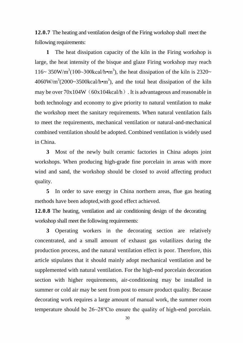
30
12.0.7 The heating and ventilation design of the Firing workshop shall meet the
following requirements:
1 The heat dissipation capacity of the kiln in the Firing workshop is
large, the heat intensity of the bisque and glaze Firing workshop may reach
116~ 350W/m3(100~300kcal/h•m
3), the heat dissipation of the kiln is 2320~
4060W/m3(2000~3500kcal/h•m
3), and the total heat dissipation of the kiln
may be over 70x104W(60x104kcal/h). It is advantageous and reasonable in
both technology and economy to give priority to natural ventilation to make
the workshop meet the sanitary requirements. When natural ventilation fails
to meet the requirements, mechanical ventilation or natural-and-mechanical
combined ventilation should be adopted. Combined ventilation is widely used
in China.
3 Most of the newly built ceramic factories in China adopts joint
workshops. When producing high-grade fine porcelain in areas with more
wind and sand, the workshop should be closed to avoid affecting product
quality.
5 In order to save energy in China northern areas, flue gas heating
methods have been adopted,with good effect achieved.
12.0.8 The heating, ventilation and air conditioning design of the decorating
workshop shall meet the following requirements:
3 Operating workers in the decorating section are relatively
concentrated, and a small amount of exhaust gas volatilizes during the
production process, and the natural ventilation effect is poor. Therefore, this
article stipulates that it should mainly adopt mechanical ventilation and be
supplemented with natural ventilation. For the high-end porcelain decoration
section with higher requirements, air-conditioning may be installed in
summer or cold air may be sent from post to ensure product quality. Because
decorating work requires a large amount of manual work, the summer room
temperature should be 26~28℃to ensure the quality of high-end porcelain.

31
For medium and low-end porcelain, the temperature may be determined based
on the process requirement.
4 Since iron filings have a great impact on the quality of ceramic
products, and ventilation and air conditioning equipment and air ducts are
closely related to the production process of production equipment, it is not
appropriate to use equipment and air ducts made of steel plates to prevent iron
filings from adhering to the green body. product quality.
12.0.10 The heating, ventilation and air conditioning design of auxiliary
workshops and auxiliary buildings shall meet the following requirements:
1 About 80% of the heat dissipation area of the equipment at the
bottom of the gas generating station is higher than that of the work zone, so
when calculating the heat consumption of heating, only 20% is calculated.
2 The heating of the compressed air station should be designed
according to the duty heating, for the following reasons:
1) Code for Design of Compressed Air Station GB 50029 requires
that the heating temperature between machines on duty during non-working
hours shall be 5℃;
2) The heat intensity of the machine room of the compressed air
station in the ceramic factory is generally greater than 23W/m3 (20 kcal/h•m
3).
When the on-duty heating is set, plus the heat dissipation of the equipment,
the room temperature of the machine may be higher than or equal to 16°C
requirement.
3 Compressed air stations with a heat intensity greater than 35W/m3in
the workshop shalluse natural ventilation or mechanical ventilation to
eliminate residual heat as their heat dissipation capacity is large.
4 The indoor design temperature of the central laboratory in summer is
26~28℃, which may also be determined according to the process
requirements.
5 Due to the large bulk density of chlorine gas which mainly

32
accumulates in the lower part of the workshop after being emitted, 2/3 of the
gas should be exhausted from the lower part.
7 The indoor calculation temperature of the instrument control room
should be determined by the needs of the instruments.
14 Energy saving
This chapter is a new chapter. The provisions of this chapter are compiled with
reference to the relevant chapters of Code for Design of Building and Sanitary
Ceramic Plant GB5060-2010.
14.1 General provisions
5 Energy conservation and comprehensive utilization of energy must be
considered in the pre-design work and design process with the site selection and
process plan. At the same time, in the preliminary design, there must be a special
discussion on the conservation and use of energy, and a comprehensive evaluation
of energy-saving measures and energy-saving effects should be made.
6 According to Decree No.44 of the National Development and Reform
Commission (NDRC) of PRC, fixed asset investment projects in China must be
conservation reviewed. Energy conservation review opinions are an important basis
for project construction, completion acceptance, and operation management.
Projects that fail to conduct energy-saving review or fail the energy-saving review in
accordance with regulations shall not start construction; projects that have been
completed shall not be put into production. Therefore, the project construction
drawing design of this provision shall implement the energy conservation review
opinions one by one.
14.2 Process energy saving
14.2.1 The kiln is the most important thermal equipment in ceramic enterprises,
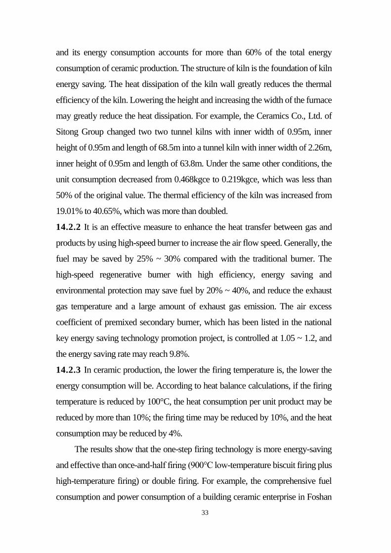
33
and its energy consumption accounts for more than 60% of the total energy
consumption of ceramic production. The structure of kiln is the foundation of kiln
energy saving. The heat dissipation of the kiln wall greatly reduces the thermal
efficiency of the kiln. Lowering the height and increasing the width of the furnace
may greatly reduce the heat dissipation. For example, the Ceramics Co., Ltd. of
Sitong Group changed two two tunnel kilns with inner width of 0.95m, inner
height of 0.95m and length of 68.5m into a tunnel kiln with inner width of 2.26m,
inner height of 0.95m and length of 63.8m. Under the same other conditions, the
unit consumption decreased from 0.468kgce to 0.219kgce, which was less than
50% of the original value. The thermal efficiency of the kiln was increased from
19.01% to 40.65%, which was more than doubled.
14.2.2 It is an effective measure to enhance the heat transfer between gas and
products by using high-speed burner to increase the air flow speed. Generally, the
fuel may be saved by 25% ~ 30% compared with the traditional burner. The
high-speed regenerative burner with high efficiency, energy saving and
environmental protection may save fuel by 20% ~ 40%, and reduce the exhaust
gas temperature and a large amount of exhaust gas emission. The air excess
coefficient of premixed secondary burner, which has been listed in the national
key energy saving technology promotion project, is controlled at 1.05 ~ 1.2, and
the energy saving rate may reach 9.8%.
14.2.3 In ceramic production, the lower the firing temperature is, the lower the
energy consumption will be. According to heat balance calculations, if the firing
temperature is reduced by 100°C, the heat consumption per unit product may be
reduced by more than 10%; the firing time may be reduced by 10%, and the heat
consumption may be reduced by 4%.
The results show that the one-step firing technology is more energy-saving
and effective than once-and-half firing (900℃ low-temperature biscuit firing plus
high-temperature firing) or double firing. For example, the comprehensive fuel
consumption and power consumption of a building ceramic enterprise in Foshan
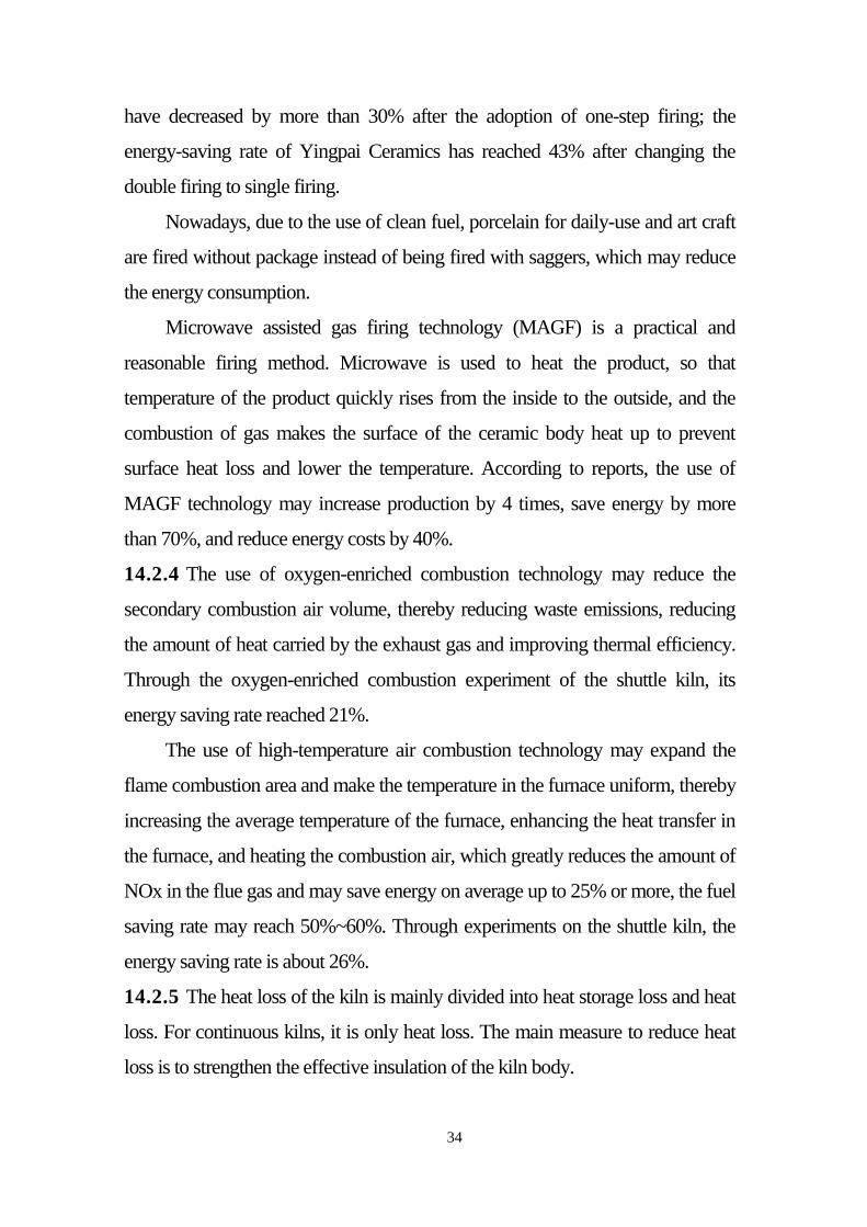
34
have decreased by more than 30% after the adoption of one-step firing; the
energy-saving rate of Yingpai Ceramics has reached 43% after changing the
double firing to single firing.
Nowadays, due to the use of clean fuel, porcelain for daily-use and art craft
are fired without package instead of being fired with saggers, which may reduce
the energy consumption.
Microwave assisted gas firing technology (MAGF) is a practical and
reasonable firing method. Microwave is used to heat the product, so that
temperature of the product quickly rises from the inside to the outside, and the
combustion of gas makes the surface of the ceramic body heat up to prevent
surface heat loss and lower the temperature. According to reports, the use of
MAGF technology may increase production by 4 times, save energy by more
than 70%, and reduce energy costs by 40%.
14.2.4 The use of oxygen-enriched combustion technology may reduce the
secondary combustion air volume, thereby reducing waste emissions, reducing
the amount of heat carried by the exhaust gas and improving thermal efficiency.
Through the oxygen-enriched combustion experiment of the shuttle kiln, its
energy saving rate reached 21%.
The use of high-temperature air combustion technology may expand the
flame combustion area and make the temperature in the furnace uniform, thereby
increasing the average temperature of the furnace, enhancing the heat transfer in
the furnace, and heating the combustion air, which greatly reduces the amount of
NOx in the flue gas and may save energy on average up to 25% or more, the fuel
saving rate may reach 50%~60%. Through experiments on the shuttle kiln, the
energy saving rate is about 26%.
14.2.5 The heat loss of the kiln is mainly divided into heat storage loss and heat
loss. For continuous kilns, it is only heat loss. The main measure to reduce heat
loss is to strengthen the effective insulation of the kiln body.
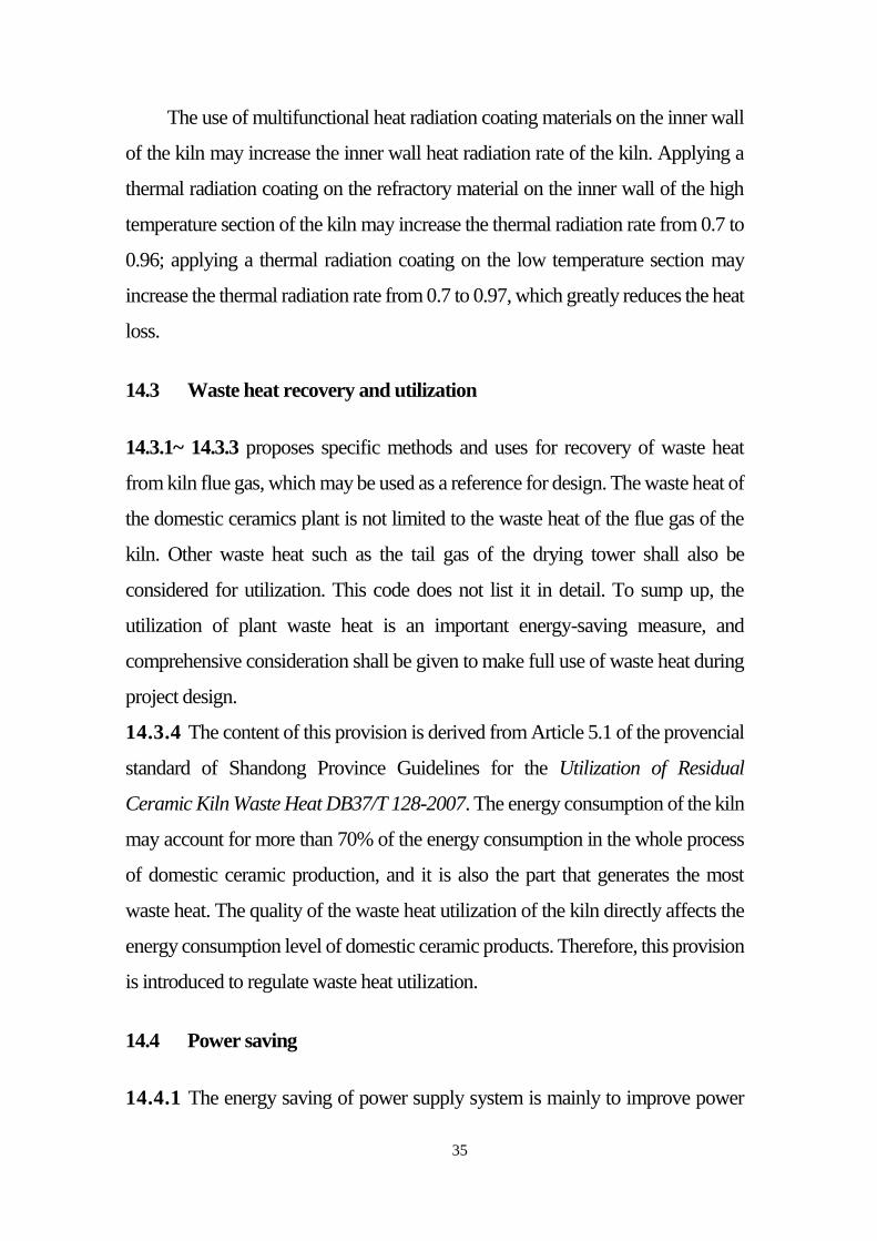
35
The use of multifunctional heat radiation coating materials on the inner wall
of the kiln may increase the inner wall heat radiation rate of the kiln. Applying a
thermal radiation coating on the refractory material on the inner wall of the high
temperature section of the kiln may increase the thermal radiation rate from 0.7 to
0.96; applying a thermal radiation coating on the low temperature section may
increase the thermal radiation rate from 0.7 to 0.97, which greatly reduces the heat
loss.
14.3 Waste heat recovery and utilization
14.3.1~ 14.3.3 proposes specific methods and uses for recovery of waste heat
from kiln flue gas, which may be used as a reference for design. The waste heat of
the domestic ceramics plant is not limited to the waste heat of the flue gas of the
kiln. Other waste heat such as the tail gas of the drying tower shall also be
considered for utilization. This code does not list it in detail. To sump up, the
utilization of plant waste heat is an important energy-saving measure, and
comprehensive consideration shall be given to make full use of waste heat during
project design.
14.3.4 The content of this provision is derived from Article 5.1 of the provencial
standard of Shandong Province Guidelines for the Utilization of Residual
Ceramic Kiln Waste Heat DB37/T 128-2007. The energy consumption of the kiln
may account for more than 70% of the energy consumption in the whole process
of domestic ceramic production, and it is also the part that generates the most
waste heat. The quality of the waste heat utilization of the kiln directly affects the
energy consumption level of domestic ceramic products. Therefore, this provision
is introduced to regulate waste heat utilization.
14.4 Power saving
14.4.1 The energy saving of power supply system is mainly to improve power

36
factor, supplemented by improving equipment utilization and reducing no-load
loss. The power factor on the electrical line of general factories may be
compensated to 0.95, with no less than 0.92 as the better. When the workshop
adopts on-site compensation, the unbalanced load shall be compensated
separately. The indirect energy consumption of nonferrous metals and other
materials shall be taken into account in the operation load rate of transformer.
14.4.2 The efficiency of electrical equipment has a great impact on power
consumption. New advanced motor and electric heating equipment shall be
applied to save power. Advanced process design is the key, which is mainly
reflected in the saving of manpower and power and the improvement of
efficiency. Therefore, selecting advanced equipment on the basis of advanced
technology may achieve the best effect of power saving.
14.4.3 Using cold light sources to improve luminous efficiency, metal halide
lamps have become the first choice for plant lamps due to their good light
efficiency and color temperature. Since human eyes are extremely sensitive to the
color of light produced by energy-saving lamps, the use of energy-saving lamps
may appropriately reduce the luminous flux, and energy-saving lamps also have
higher luminous efficiency.
15 Environmental protection
15.1 General provisions
15.1.1 The national and industry environmental protection standards and
regulations that shall be implemented mainly include:
1 Regulations on the Environmental Protection Management of
Construction Projects-State Council Order [2017] No. 682
2 Code for Design of Environmental Protection of Chemical Industry
Projects GB 50483
3 Emission Standard of Pollutants for Ceramics Industry GB 25464
37
4 Integrated Wastewater Discharge Standard GB 8978
5 Emission Standard of Air Pollutants for Industrial Kiln and Furnace
GB 9078
6 Code for the Dust Protecting Technique of the Ceramic Production
GB 13691
7 Emission Standard of Air Pollutants for Boiler GB 13271
8 Ambient Air Quality Standards GB 3095
9 Emission Standard for Industrial Enterprise Noise at Boundary GB
12348
10 Hygienic Standards for the Design of Industrial Enterprises GBZ 1
11 Safety Code for Gas of Industrial Enterprises GB 6222
12 Code for Design of Noise Control of Industrial Enterprises GB/T
50087.
15.2 Waste water
15.2.1 There is silicate mixture in raw materials of raw materials of domestic
ceramics factory, equipment of Forming workshop and ground washing sewage.
Silicate mixture is of high turbidity and large ratio. Large particles precipitate
quickly, and fine particles are difficult to settle, forming stable sol system in water.
Due to the different raw materials, the water quality changes greatly. Generally,
the pH of sewage is 6.5 ~ 8, and the turbidity is 2000 ~ 28600 mg / L. The amount
of sewage varies with the production scale and operation management methods.
Coagulation sedimentation filtration is a general treatment. The type and quantity
of coagulant added in the treatment are determined by experiment.
15.3 Waste gas
38
15.3.2 The height of the kiln exhaust chimney shall be determined by resistance
calculation, with minimum value not less than 15m. When there are buildings
within a radius of 200m around the chimney, the height of the chimney shall also
be 3m higher than the highest building.
15.3.3 The exhaust gas of the boiler shall comply with the above mentioned
codes in the articles, and the design shall be based on the higher standard
requirements.
15.4 Waste solids
15.4.2 Most of the combustion methods of heating boilers and gas station fuels
in domestic ceramics plants afopts grate-fired furnaces, and the ash may be used
for ash bricks. At present, most of the building materials departments in cities
above the county level have founded ash and slag brick factories, which are in line
with the national principle ofreducing occupy of cultivated land for building
materials. Therefore, utilization of ash and slag is prospective.
15.4.3 The ash and slag storage yard should be located in the valley near the
plant site, supplemented by water sealing or covering with layers of soil to prevent
dust from flying.
15.5 Noise
It is more economic to control the occurrence of noise or reduce the degree of
radiated noise than to control the noise after it is formed. Methods such as rubber
lining of ball mills and silent ventilator are applicable. It shall be considered in the
architectural design and general layout design to reduce the the impact of noise
equipment on the environment.
16 Occupational safety and health

39
This chapter is a new chapter. The provisions of this chapter are compiled with
reference to the relevant chapters of Code for design of building and sanitary
ceramic plant GB 50560-2010.
16.1 General provisions
16.1.1 Comprehensive mechanization and automation of production design of
ceramics plant shall be improved. For various occupational hazards in the
production process, the principles of elimination, prevention, weakening, isolation,
interlocking and warning shall be followed, and corresponding technologies shall
be adopted in each descipline. Measures are taken to improve the working
codition and promoting safe and efficient production.
16.4 Lightning protection
16.4.2 Acurate statistics of the local geological and meteorological conditions
shall be aquired in the lightning design, buildings that need lightning protection
shall be classified. The classification standards should comply with the relevant
provisions in the Design code for protection of Structures against lightning GB
50057.
Plants, dormitories, and office buildings in areas prone to thunderstorms are
classified as Class II lightning protection buildings. Because the improvement of
lightning protection devices does not take up a lot of investment, in the
classification of lightning protection buildings, buildings in the fuzzy boundary
may be designed according to a higher level of lightning protection to ensure
safety.
16.7 Noise control
16.7.5 Damping and sound insulation measures are taken on the steel slide pipe
and steel silo wall to avoid noise caused by direct impact of unsmooth materials.

40