code of practice for the quality assurance and control for...
TRANSCRIPT
Netherlands Commission on Radiation Dosimetry Subcommittee “IMRT QA”, June 2013
Code of Practice for the Quality Assurance and Control
for Intensity Modulated Radiotherapy
NEDERLANDSE COMMISSIE VOOR STRALINGSDOSIMETRIE
Report 22 of the Netherlands Commission on Radiation Dosimetry
June 2013

Disclaimer regarding NCS reports The NCS frequently publishes reports for fellow professionals in which recommendations are given for
various quality control procedures or otherwise. The members of the NCS board and the members of
the concerning subcommittee do not claim any authority exceeding that of their professional expertise.
Responsibility on how the NCS recommendations are implemented lies with the user, taking into
account the practice in his/her institution.
i
Preface
The Nederlandse Commissie voor Stralingsdosimetrie (NCS, Netherlands Commission on
Radiation Dosimetry, http://www.radiationdosimetry.org) was officially established on 3
September 1982 with the aim of promoting the appropriate use of dosimetry of ionising
radiation both for scientific research and practical applications. The NCS is chaired by a
board of scientists, installed upon the suggestion of the supporting societies, including the
Nederlandse Vereniging voor Radiotherapie en Oncologie (Netherlands Society for
Radiotherapy and Oncology), the Nederlandse Vereniging voor Nucleaire Geneeskunde
(Dutch Society of Nuclear Medicine), the Nederlandse Vereniging voor Klinische Fysica
(Dutch Society for Medical Physics), the Nederlandse Vereniging voor Radiobiologie
(Netherlands Radiobiological Society), the Nederlandse Vereniging voor Stralingshygiëne
(Netherlands Society for Radiological Protection), the Nederlandse Vereniging voor
Medische Beeldvorming en Radiotherapie (Dutch Society for Medical Imaging and
Radiotherapy), the Nederlandse Vereniging van Klinisch Fysisch Medewerkers (Dutch
Society for Medical Physics Engineers), the Nederlandse Vereniging voor Radiologie
(Radiological Society of the Netherlands) and the Belgische Vereniging voor
Ziekenhuisfysici/Société Belge des Physiciens des Hôpitaux (Belgian Hospital Physicists
Association). To pursue its aims, the NCS accomplishes the following tasks: participation in
dosimetry standardisation and promotion of dosimetry intercomparisons, drafting of
dosimetry protocols, collection and evaluation of physical data related to dosimetry.
Furthermore, the commission shall maintain or establish links with national and international
organisations concerned with ionising radiation and promulgate information on new
developments in the field of radiation dosimetry.
Current members of the board of the NCS:
J.B. van de Kamer, Chairman T.W.M. Grimbergen, Vice-Chairman
J. de Pooter, Secretary J.M.J. Hermans, Treasurer
A. Van Der Plaetsen A. Spilt
F.W. Wittkämper D. Zweers
A.A. Lammertsma P. Sminia
K. Franken

ii
Code of Practice for the Quality Assurance and Control
for Intensity Modulated Radiotherapy June 2013
This report was prepared by a subcommittee of the Netherlands Commission on Radiation
Dosimetry (NCS), consisting of Belgian and Dutch scientists.
Members of the subcommittee:
E. van der Wal, chairman
J. Wiersma, secretary
A.H. Ausma
J.P. Cuijpers
M. Tomsej
L.J. Bos
G. Pittomvils
L. Murrer
J.B. van de Kamer
NCS, Delft, The Netherlands
For more information on NCS reports, see http://www.radiationdosimetry.org

iii

iv
Contents
Preface .................................................................................................................................. i
Summary .............................................................................................................................. 6
Abbreviations ...................................................................................................................... 8
1. Introduction .................................................................................................................11
2. Linear accelerator Quality Assurance for IMRT: Acceptance, Commissioning and Quality Control. ..................................................................................................................15
2.1. Introduction .............................................................................................................. 15
2.2. General remarks regarding measurements.............................................................. 18
2.3. NCS Recommendations of Tests during Acceptance, Commissioning and QC ....... 19
2.4. Description of performance tests for IMRT............................................................... 21
3. Commissioning a treatment planning system used for IMRT ..................................32
3.1. Introduction .............................................................................................................. 32
3.2. Background for the leaf modelling ........................................................................... 32
3.3. Recommendations for leaf modelling ....................................................................... 35
3.4. Dose calculations outside field edges ...................................................................... 39
3.5. Modelling of Small Fields ......................................................................................... 40
3.6. The modelling of bi-directional off-axis beams ......................................................... 41
3.7. Verification of TPS in inhomogeneous phantoms (calculation algorithms) ............... 43
3.8. Verification of the optimization algorithm ................................................................. 43
3.9. Systematic sequence of the commissioning of an IMRT planning system ............... 44
4. Patient Specific QA .....................................................................................................47
4.1. Introduction .............................................................................................................. 47
4.2. Definitions used in patient-specific QA ..................................................................... 47
4.3. Gamma analysis ...................................................................................................... 48
4.4. Validation of plan transfer ........................................................................................ 48
4.5. Methods .................................................................................................................. 49
4.6. Development of class solutions ............................................................................... 55
4.7. Recommendations on patient-specific QA ............................................................... 59
5. Risk Analysis in IMRT .................................................................................................63
5.1. Purpose ................................................................................................................... 63
5.2. Scope ...................................................................................................................... 64

v
5.3. Legislations, regulations and initiatives .................................................................... 64
5.4. Available Methods ................................................................................................... 66
5.5. HFMEA / SAFER ..................................................................................................... 66
5.6. SAFER in IMRT – design of the Prospective Risk Inventory .................................... 68
5.7. SAFER in IMRT - results ......................................................................................... 69
5.8. Risk profile in radiotherapy ...................................................................................... 72
5.9. Recommendations ................................................................................................... 74
Acknowledgements ............................................................................................................76
References ..........................................................................................................................77
6
Summary
In September 2009, the NCS set up a new subcommittee to devise guidelines for
quality assurance (QA) for Intensity Modulated Radiotherapy (IMRT) treatments.
Although these guidelines are primarily focused on IMRT treatments in Belgian and
Dutch clinics, other institutes should also be able to benefit from the report.
We chose to base our work on the foundations laid in previous NCS reports (1–3)
and focused ourselves in the report on the more stringent demands on
commissioning, treatment planning and QA for IMRT. IMRT treatments pose stricter
requirements on both geometric and dosimetric accuracy of the linear accelerator
compared to more conventional treatments.
The report starts with an overview of reports on the accuracy of IMRT treatments in
Europe and the United States of America, demonstrating the value of proper IMRT
QA protocols. The second chapter deals with the IMRT-specific demands on the
linear accelerator and the commissioning of such a system before clinical use. In that
chapter general requirements and proposals are given measuring devices, methods
and frequencies for commissioning and regular QA. Special attention is given to
small-field dosimetry and mechanical and dosimetric optimization and
characterization of the Multi-Leaf Collimator (MLC) system. Chapter three considers
the possibilities and demands to ensure optimal correspondence between predicted
dose distributions by the planning systems and actually delivered dose distributions
by the linear accelerator. In particular, we address leaf tip modelling, interleaf
leakage and leaf transmission for either sliding window or step-and-shoot IMRT
techniques and tongue and groove effects for step-and-shoot IMRT. In chapter four,
recommendations are given to perform patient-specific IMRT QA, both pre-treatment
and in-vivo dosimetry. We classify different measuring devices regarding their
dosimetric accuracy and/or spatial resolution and present recommendations on how
to organize patient specific QA using different classes of measurement. For both new
and experienced users, ways to develop and test new class solutions are presented,
enabling a safe way to start using them.
Finally, in chapter five we present a way to set up a risk analysis for IMRT. We briefly
touch upon some law and regulations concerning risk analysis and some available
methods to perform such an analysis. We discuss the SAFER method in more detail
since we consider it to be the most practical method for our purposes. Several
examples are given in the document and in the supplementary Excel spread sheet.
7
These should be taken as a starting point for a risk analysis and not be considered
as an exhaustive analysis.
Although the subcommittee has made every effort to be as complete as possible, the
user is strongly recommended to apply and modify our recommendations to the local
situation. This document should help setting up a proper QA system for the safe and
proper implementation of IMRT in clinical practice but may not be tailored for all types
of equipment and/or institutes.

8
Abbreviations
AAA Anisotropic Analytic Algorithm
AAPM American Association of Physicists in Medicine
aSi Amorphous Silicon
ASTRO American Society for Radiation Oncology
CAX Central Axis
CCC Collapsed Cone Convolution
CCW Counter Clock Wise
CT Computed Tomography
CW Clock Wise
CWG Collaborative Work Group
DICOM Digital Imaging and Communications in Medicine
DLG Dosimetric Leaf Gap
DLS Dosimetric Leaf Separation
DTA Distance to Agreement
DVH Dose Volume Histogram
EBT External Beam Treatment
EMR Electronic Medical Record
EPID Electronic Portal Imaging Device
ESTRO European SocieTy for Radiotherapy and Oncology
EUD Equivalent Uniform Dose
EURATOM The European Atomic Energy Community
FWHM Full Width Half Maximum
GORTEC Groupe Oncologie Radiothérapie Tête et Cou
HAZOP Hazard and Operability
HFMEA Healthcare Failure Mode Effect Analysis
HKZ Harmonisatie Kwaliteitsbeoordeling in de Zorgsector
IAEA International Atomic Energy Agency
ICRP International Commission on Radiological Protection
IEC International Electro technical Commission
IMRT Intensity-Modulated Radiation Therapy

9
IPEM Institute of Physics and Engineering in Medicine
JCAHO The Joint Commission on Accreditation of Healthcare Organizations
MC Monte Carlo
MLC Multi-Leaf Collimator
MOSFET Metal-Oxide-Semiconductor Field-Effect Transistor
MSF Modulation Scaling Factor
MU Monitor Unit
NCRP National Council on Radiation Protection & Measurements
NEN NEderlandse Norm
NIAZ Nederlands Instituut voor Accreditatie in de Zorg
NMED Nuclear Medical Events Database
NRC National Research Counsel
NTA Nederlandse technische afspraak
NVKF Nederlandse Vereniging voor Klinische Fysica
OAR Organ at Risk
OECI Organisation of European Cancer Institutes
OF Output Factor
PDD Percentage Depth Dose
PRISMA-
RT
Prevention, Recovery and Information System for Monitoring and
Analyses in RadioTherapy
PTV Planning Target Volume
QA Quality Assurance
(set of policies and procedures to maintain the quality of patient care)
QC
Quality Control
(set of procedures/tests to validate equipment is operating within
tolerance)
R&V Record & Verify
ROSIS Radiation Oncology Safety Information System
RPC-RTOG Radiological Physics Center - Radiation Oncology Group
RT Radiotherapy
RTT Radiotherapy Technologist

10
SAFER Scenario Analyse van Faalwijzen Effecten en Risico's
Sc Head Scatter Factor
Scp Total Scatter Factor
SIL Safety Integrity Level
SIRE Systematic Incident Reconstruction and Evaluation
SS Step and Shoot
SSD Source Surface Distance
SW Sliding Window
TECDOC Technical Documents
TG Task Group (of the American Association of Physicists in Medicine)
TJC The Joint Commission
TLD Thermo luminescent Dosimeter
TPS Treatment Planning System
VMAT Volumetric Modulated Arc Therapy
VMS Veiligheids Management Systeem
WHO World Health Organisation
11
1. Introduction
Intensity Modulated RadioTherapy (IMRT) has become widely clinically available
since the beginning of this millennium and is nowadays in routine clinical practice in
almost all radiotherapy institutes in the Netherlands and Belgium. There are multiple
technological concepts that are commercially available enabling IMRT treatment
delivery that are quite different from each other: i) MLC-based systems using a
conventional linear accelerator (using either static or dynamic techniques), ii) a
tomographic system which is based on a helical slice-wise delivery technique and iii)
robotic systems that use many small beam segments. Recently, also volumetric
modulated arc therapy (VMAT) has become available which uses an arc delivery
technique with variable leaf-positions, gantry speed and dose rate. This report will be
restricted to MLC based systems using fixed beam angle delivery. Quality assurance
for VMAT is the subject of a separate NCS-report, which can be considered as an
extension of the current report on IMRT quality assurance.
IMRT is a complex technique that imposes high demands on the delivery system, the
treatment planning system and the users of these systems. These demands are not
always met in practice since there is evidence that IMRT treatments may not always
be as accurate as practitioners believe. Over the last years (4), two different groups
reported this assumption through dosimetry audits in IMRT treatments based on
head and neck phantom irradiations in the United States of America (5,6) and Europe
(7–9). Approximately 1/3 of the contributing institutions did not meet the accuracy
criteria (see table 1.1), even though the dose tolerance criteria were not set very
strictly. This result appears astonishing especially when these institutions were
feeling confident enough in their IMRT planning and delivery process expecting to
pass. This experience strongly suggests that some clinics have not adequately
implemented the quality assurance of their planning and delivery systems for IMRT.
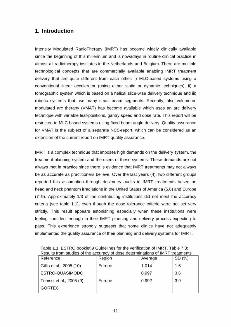
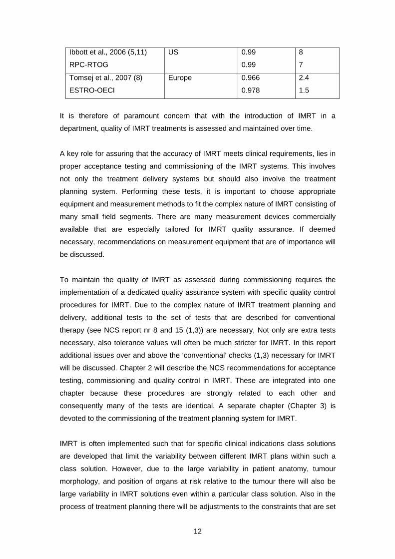
Table 1.1: ESTRO booklet 9 Guidelines for the verification of IMRT, Table 7.3: Results from studies of the accuracy of dose determinations of IMRT treatments Reference Region Average SD (%)
Gillis et al., 2005 (10)
ESTRO-QUASIMODO
Europe 1.014
0.997
1.6
3.6
Tomsej et al., 2005 (9)
GORTEC
Europe 0.992 3.9
12
Ibbott et al., 2006 (5,11)
RPC-RTOG
US 0.99
0.99
8
7
Tomsej et al., 2007 (8)
ESTRO-OECI
Europe 0.966
0.978
2.4
1.5
It is therefore of paramount concern that with the introduction of IMRT in a
department, quality of IMRT treatments is assessed and maintained over time.
A key role for assuring that the accuracy of IMRT meets clinical requirements, lies in
proper acceptance testing and commissioning of the IMRT systems. This involves
not only the treatment delivery systems but should also involve the treatment
planning system. Performing these tests, it is important to choose appropriate
equipment and measurement methods to fit the complex nature of IMRT consisting of
many small field segments. There are many measurement devices commercially
available that are especially tailored for IMRT quality assurance. If deemed
necessary, recommendations on measurement equipment that are of importance will
be discussed.
To maintain the quality of IMRT as assessed during commissioning requires the
implementation of a dedicated quality assurance system with specific quality control
procedures for IMRT. Due to the complex nature of IMRT treatment planning and
delivery, additional tests to the set of tests that are described for conventional
therapy (see NCS report nr 8 and 15 (1,3)) are necessary, Not only are extra tests
necessary, also tolerance values will often be much stricter for IMRT. In this report
additional issues over and above the ‘conventional’ checks (1,3) necessary for IMRT
will be discussed. Chapter 2 will describe the NCS recommendations for acceptance
testing, commissioning and quality control in IMRT. These are integrated into one
chapter because these procedures are strongly related to each other and
consequently many of the tests are identical. A separate chapter (Chapter 3) is
devoted to the commissioning of the treatment planning system for IMRT.
IMRT is often implemented such that for specific clinical indications class solutions
are developed that limit the variability between different IMRT plans within such a
class solution. However, due to the large variability in patient anatomy, tumour
morphology, and position of organs at risk relative to the tumour there will also be
large variability in IMRT solutions even within a particular class solution. Also in the
process of treatment planning there will be adjustments to the constraints that are set
13
for tumour coverage and organs-at-risk dose restrictions during the optimization. This
will also lead to variability in the characteristics of an IMRT plan between different
patient-specific treatment plans. For this reason, quality assurance on an individual
patient level is also required. How this is performed and how often will depend on the
experience a certain department has with IMRT as well as the complexity of the
IMRT plans. In chapter 4 the NCS provides with recommendations on how to perform
patient specific quality assurance.
Managing quality in radiation oncology, and in particular in IMRT treatments, involves
much more than just focusing on technological issues. It involves the description and
subsequent analysis of the entire process of delivering an IMRT treatment. As with
any newly introduced technique or procedure it is advised to perform a prospective
risk analysis of IMRT delivery. From such an analysis, all measures to be taken in
order to guarantee safe and accurate delivery of IMRT treatments should follow.
These will not only involve technological issues, but also the organization of the
process and the training and maintenance of the personnel that is involved in IMRT
treatments. In chapter 5 the NCS will describe a method for performing such a
prospective risk analysis.
The tests and methods described in this report are all published in the literature.
They are developed considering the system that delivers IMRT as a black box.
Depending on the experience and knowledge of the users of the systems it might
very well be that certain tests are considered to be redundant or the frequency at
which they are performed might be considered to be too high or too low. Also instead
of using the methods as described in this report one can use one’s own methods for
testing. If one determines to deviate from the recommendations, it is advised to
support this by performing a short risk analysis in which it is described and
documented why one deviates from the recommendations. If one uses an alternative
method for certain tests it is important that this method is properly validated and
adequately documented. The purpose of this report is a code of practice that serves
as a guideline to setup an appropriate system of quality assurance for IMRT. The
tests and methods should be adapted to the complexity of the intended IMRT
treatment. Depending on complexity and comprehensiveness, additional resources
(time, manpower, equipment) might be necessary for the implementation of IMRT.
The members of the NCS board and the members of the concerning subcommittee
do not claim any authority exceeding that of their professional expertise.

14
Responsibility on how the NCS recommendations are implemented lies with the user,
taking into account the practice in his/her institution.

15
2. Linear accelerator Quality Assurance for IMRT: Acceptance,
Commissioning and Quality Control.
2.1. Introduction
MLC-based intensity modulated radiotherapy (IMRT) is the result of a highly complex
automated process of delivering dose to the patient. While linear accelerator and
computer technology will inevitably proceed in the direction of self-checking and
IMRT automation, quality assurance (QA) is still a vital component to ensure that the
patient is treated accurately.
Quality of IMRT treatments begins with the choice and purchase of the equipment
(linear accelerator, treatment planning system, electronic medical record and
verification system). During the process of acquisition, considerable thought should
be given regarding requirements and specifications, depending on its intended use.
Tolerances should be chosen depending on the complexity of the IMRT technique.
Although design tolerances or standard specifications as given by the manufacturer
have to be considered seriously, the basic assumption should be that criteria are
driven by and satisfy (future) clinical use (12). As a consequence it is not unusual to
ask for additional and more stringent demands, these (additional) requirements
should be explicitly requested as part of the contract of sale.
For conventional 3D conformal radiotherapy, it is recommended to set up QA
procedures according to NCS report 8 (3). However, it is acknowledged that
compared to conventional 3D conformal radiotherapy specific recommendations –
new tests and tolerances, especially for the MLC – are needed when performing
IMRT (13). For instance, to achieve sufficient geometric and dosimetric accuracy,
each of the many subsystems involved in the IMRT delivery chain has to comply to
very strict tolerance values because all errors contribute to the total uncertainty. This
NCS report wants to emphasize this, but at the same time recognizes the difficulty of
translating (deviations from) mechanical and dosimetric tolerances into clinical
consequences. Investigation in this area, e.g. the clinical significance of MLC
positional errors (14–16) is sparse and more research is required. Therefore,
tolerances given in this chapter are derived from what is currently achievable with the
modern radiotherapy equipment or estimated from dosimetric consequences rather
than from clinical indicators.
In this chapter, the acceptance, commissioning and quality control aspects of the
crucial components in the IMRT delivery chain are addressed. The tests

16
recommended by NCS are summarized in Table 1 in paragraph 2.3, whereas a more
detailed description of the tests is given in paragraph 2.2.
2.1.1. Acceptance
Before using a linear accelerator clinically, performing acceptance tests and quality
control is a statutory requirement in The Netherlands (Besluit stralingsbescherming,
2013 art.10, part 2; commentary art. 67): “The owner takes care that a new or
changed source (such as a linear accelerator) will not come into use before
conducting an acceptance test by a qualified expert (e.g. a radiation protection
officer) and meets with his approval.” But also if it concerns a change of technique
(i.e. change in use) rather than introducing new equipment, an acceptance test is
highly recommended by the NCS.
The framework of linear accelerator acceptance is described in several international
reports (18,19,13) and is characterized by:
1) the safe use of equipment from a radiation protection point of view
2) the demonstration that functional linear accelerator performance meets the
criteria defined beforehand as part of the contract
3) recording baseline values for future QC
As acceptance results in general can (and will) be used as baseline values for future
QC, the requirements may be more stringent than employed during on-going linear
accelerator quality control.
During the acceptance phase, focus will be on the technical and dosimetric aspects
of the dose delivery but also safety checks like the handling of beam interruptions by
the verification and control system are addressed.
2.1.2. Commissioning
Commissioning of IMRT is defined as the initial acquisition and documentation of all
necessary dosimetric and mechanical data to enable clinical use, including a
verification step with phantom studies (20,10). This verification step shows that IMRT
treatments can be planned, transferred, and delivered with sufficient accuracy. Note
that this is different from per-patient phantom measurements for QA purposes. Here
we focus on the commissioning of machine performance specific for IMRT whereas
the validation of clinical treatment delivery is dealt with in chapter 4.

17
Obviously, some tests will be done during the acceptance phase of the linear
accelerator (MLC transmission, etc.), but they may have to be repeated, extended
and/or made more precise during commissioning.
Also additional tests and measurements may be performed that are not part of
acceptance protocols, like the acquisition of small field beam data and the accurate
determination of the dosimetric properties of the MLC (needed for TPS modelling,
chapter 3).
2.1.3. Quality Control
To validate accurate IMRT dose delivery the stability of the system with respect to
the baseline data acquired during acceptance and commissioning has to be checked
on a regular basis. The test frequency with respect to baseline data depends on the
expected stability of the system’s components. The NCS will recommend minimum
frequencies. However, the frequency of IMRT specific checks can be adapted over
time based on the observed stability of the specific machine parameters.

18
2.2. General remarks regarding measurements
Stringent demands on tolerances for IMRT are also reflected on the measurement
equipment used. It is important to stress the fact that measurement equipment
should be able to perform (in terms of uncertainties, repeatability, and precision)
within the tolerance or action level of the parameter to be measured. AAPM TG142
(13) states “that the measurement system and procedure repeatability be such that
two standard deviations for three or more repeated consecutive measurements are
less than the tolerance value”. This statement indicates the need of quality control on
measurement tools and equipment. One should familiarize oneself with the suitability
of its use (in terms of possibilities as well as limitations). For example, a functional
acceptance test of the water phantom might be performed in order to assess the
(mechanical) tolerances of the phantom. Simple characteristics as geometrical
accuracy, hysteresis and reproducibility determine largely if the phantom can or
cannot be used for IMRT acceptance and commissioning. Besides investigating
mechanical issues of the water phantom, try to determine (estimate) the influence of
detector characteristics (in terms signal-to-noise and leakage, effective point of
measurement, stability and reproducibility) on the measurement uncertainty.
Small field dosimetry requires special attention and a careful selection of the
measurement equipment and conditions is of major concern. For example, deviation
of the scanning device in depth from the real central axis of the beam might result in
a wrong percentage depth dose curve. A large set of specialised studies is available
in literature dealing with this critical topic (21–26).
The different dosimetric characteristics of different detectors should be balanced
against the parameters needed for IMRT modelling. An ideal detector should have:
� an excellent spatial resolution (small volume)
� dose response which is independent of energy, dose and dose rate
� excellent stability, linearity and reproducibility
No commercially available detector (status at January 2013) fulfils all these criteria.
Therefore, the NCS recommends measuring by selecting detectors with
complementary characteristics and measure several overlapping field sizes. By
performing cross checking reliable dosimetry can be performed (26,27).

19
2.3. NCS Recommendations of Tests during Acceptance, Commissioning and QC
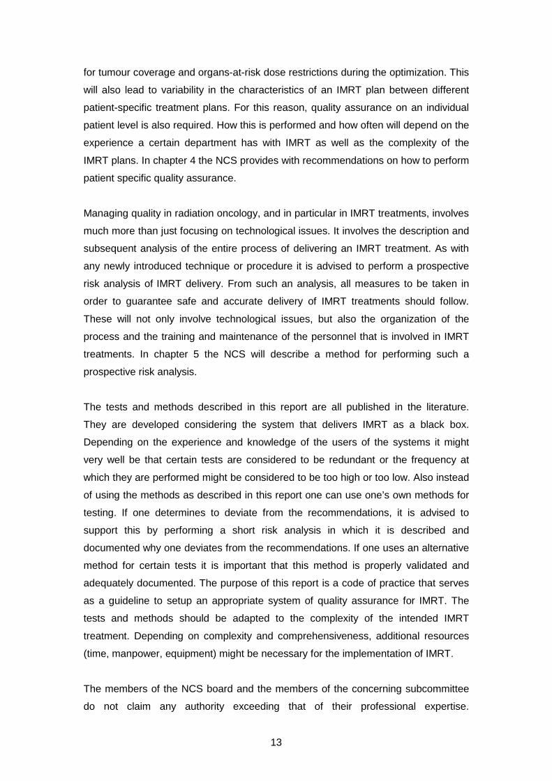
2.3.1. Overview of tests
In this section an overview will be given of tests that are advised in each phase of the
Quality Assurance programme for the linear accelerator (table 2.2) during
acceptance and/or commissioning and quality control. The last column gives the
advised frequencies for quality control of the performance of the machine as
determined and documented during acceptance testing and commissioning. As
stated before, one may deviate from this frequency depending on experience gained
on linac stability, also related to type and age of the equipment.
20
Table 2.1: Overview of recommended tests for acceptance, commissioning and quality control
Procedure group
Procedure detail Description Delivery technique
Acceptance Commissioning QC Frequency
Isocentre Winston Lutz test, MLC star shot
2.4.1.1, page 21
SS, SW X Annually
MLC Leaf / jaw position
accuracy (calibration) 2.4.1.2, , test A, page 23
SS, SW X X Monthly
Leaf / jaw position accuracy (Garden/Picket Fence)
2.4.1.2, test A, page 23,
SS, SW X Monthly
Leaf / jaw position reproducibility
2.4.1.2, test B, page 24
SS, SW X Annually
Dosimetric leaf separation
2.4.1.2, test C, page 24
SW X X After corrective maintenance
Leaf gap stability 2.4.1.2, test D, page 24
SW X Quarterly
Leaf speed stability 2.4.1.2, test E, page 24
SW X Quarterly
Gantry angle dependence
2.4.1.2, , test F, page 24
SS, SW X Annually
Dosimetry MLC transmission 2.4.2.1,
page 25 SS, SW X (X)
Dose monitor: reproducibility
2.4.2.2, test A, page 26
SS X After corrective maintenance
Dose monitor: proportionality
2.4.2.2, test B, page 27
SS, SW X After corrective maintenance
Dose monitor: beam profile stability (at start up)
2.4.2.2, test B, page 27
SW After corrective maintenance
Dose monitor: beam profile stability (at start up)
2.4.2.2, test C, page 27
SS X Annually & After corrective maintenance
Radiation safety 2.4.3, page 28
SS, SW X
Small field beam data 2.4.4 page 29
SS, SW X
Beam interruptions 2.4.5 page 31
SS, SW X

21
2.4. Description of performance tests for IMRT
In this section, a detailed description of tests that are considered to be of importance
for the performance of linear accelerators with respect to MLC based IMRT is
discussed.
2.4.1. Mechanical tests
This paragraph contains the description of mechanical tests considered to be of
importance for IMRT treatment quality assurance.
2.4.1.1. Mechanical machine alignment
• Goal
To ensure that mechanical axes of rotation (collimator, gantry and table) are well
established as a basis for a geometric accurate treatment.
• Background
When implementing IMRT, special attention should be paid to the leaf calibration
and the alignment of the collimators with the source (IPEM report 103 (24)) to
ensure proper alignment of IMRT segments at multiple gantry angles and
collimator rotations. For a calibration at sub-millimetre level it is advised to
minimize the mechanical isocentre walkout before starting measurements for
IMRT, especially where small field are involved.
• Suggested tests
Several tests are described in the literature (e.g. Winston Lutz test, starshots or
spoke films) of which some also include the radiation isocentre accuracy (28,29).
Determine the walkout of the optical crosswire projection relative to a fixed point
(e.g. pointer, marked crosswire or laser) as a function of collimator, gantry and
table rotation (table: e.g. Karger (30)). Normally mechanical adjustment of the
gantry arm, collimator and table are only performed during installation.
• Recommended tolerances for the mechanical isocentric accuracy
As a baseline, with full rotation of the radiation head, the locus of the collimator
rotation axis should be contained within a 0.5 mm diameter circle at 100 cm.
(Current NCS-8 recommendation is 1 mm at isocentre level (3))

22
The sphere containing the gantry isocentre (defined by the projected crosswires
at all gantry angles) is in general a bit larger due to sagging of the gantry and
should lie preferably within a 1.0 mm diameter circle, but at worst within a 1.5 mm
diameter circle. (Current NCS-8 recommendation is 2 mm).
Concerning the couch isocentre, the locus of the projected crosswires (while
turning the couch from 90° to 270°) should be contained within a semi-circle of
1.0 mm in diameter (isocentric height). (Current NCS-8 recommendation is 2 mm
at isocentre level). It should be noted however, that use of couch rotations with
IMRT is usually limited.
All three axes (gantry, collimator and couch) should coincide preferably within a
1.5 mm sphere but at least within 2 mm.
2.4.1.2. Leaf and jaw positioning
• Goal
To ensure that absolute leaf and collimating jaw positioning errors are within
tolerance.
• Background
The conventional use of the MLC concerns the aperture shaping of single fields.
IMRT on the other hand is characterized by the use of many small segments
(step and shoot) or leaf gaps (dynamic delivery), in which case incorrect positions
of leaves may have a large impact on relative as well as on absolute dose within
the target as well as the OARs. Therefore, there is a need for tighter tolerances
regarding the positioning of the leaves. Since many MLC systems were originally
not designed to deal with IMRT, attention should be given to certain MLC-
characteristics in view of the wider range of leaf positions used, dealing with over-
travel and field abutments (31,32,19,33).
Mechanical components like jaws, MLC leaf banks and MLC leaves are always
designed with a little backlash in order to facilitate friction free motion. Leaf
motion (dynamic) or position (step and shoot) may be affected by gravitational
effects at gantry angles different from 0°. MLC leaves can run with a maximum
leaf speed which may decrease due to wear of mechanical components or build-
up of dirt. For segmental IMRT these issues will lead to increase of delivery time.
23
For sliding window treatments reduction of leaf speed will lead to an increase of
beam-holds and may also compromise dose delivery accuracy.
Both accuracy (the absolute leaf position) and precision (how well can the MLC
reproduce a leaf position) need to be investigated. Tests might be vendor specific
(e.g. Varian: LoSasso, 2008 (34); Elekta: Liu et al. 2008 (35); Siemens: Bayouth,
2008 (36)).
• Suggested tests
A Leaf and jaw position calibration & verification
The method for the absolute calibration of leaf banks and collimating jaws
(including over-travel positions) should be sensitive to detect deviations from a
desired value in relation to its tolerance level. Methods depend on the MLC
model (positioning based on a camera- or encoder system) and IMRT technique
used (step and shoot, dynamic). Some of these methods might be provided by
the vendor, see the vendor technical documentation for details.
Although film dosimetry and EPID are used for verification and routine QC, it is
advised to use a scanning motorized water phantom (tested for position accuracy
and hysteresis, AAPM TG 106, 2008 (37)) with a small detector (e.g. diode,
diamond) to validate the method for assessment of leaf-positioning.
A useful method to check whether leaf positioning errors as a function of MU are
within tolerance limits is the Garden Fence test (38,34,39). The Garden Fence
consists of a leaf motion file (containing leaf-positions as a function of MU’s) with
small leaf gaps at multiple predefined positions. Positions and gaps are identical
for all leaf pairs. A visual check of the resulting dose on film can detect leaf
positioning errors of 0.5 mm (40). Also EPID can be used (41). If a motor encoder
shows loss of counts, this will be reflected in leaf positioning errors. Also a test
consisting of adjacent segments (also known as Picket Fence) comparable to
LoSasso’s Garden Fence has been proposed (42–44). Visual analysis of these
fence tests has to be performed with a high resolution detection method such as
film or portal imaging.
To obtain a quantitative measurement of deviations, a method using a (1D) diode
array has been proposed (35). The same can be done with an (2D) ion chamber
array, where the chambers’ response can be used as an indicator of leaf position
accuracy (45,46).

24
B Leaf and jaw position reproducibility
Next to accuracy, the leaf position (and collimating jaw) reproducibility should be
measured. This can be done by repeated measurements in which leaves or
collimators are moved from an inner to outer position or vice versa to reach a
certain position (n≥3 for both situations). Note: if for instance a water phantom is
used, use the same scan direction at all times or correct for hysteresis of the
scanning device.
C Dosimetric leaf separation (for SW only)
The dosimetric leaf separation (DLS) reflects the widening of the radiation field
compared to the light field due do to the rounded MLC leaf edges and is used to
model the extra transmission through the rounded leaf ends of the Varian MLC.
The dosimetric leaf separation or dosimetric leaf gap can be determined by the
integral dose method using sweeping gaps of various widths (47–49). A tolerance
of 0.1 mm is advised.
D Dosimetric Leaf gap stability test (for SW only)
Mechanical tolerances as well as the wear and tear may cause variations in gap
width, compromising dosimetric accuracy. Dosimetric leaf gap stability can be
assessed by measuring the dose from a narrow sliding window that creates a
uniform dynamic field and using a single dosimeter with sufficient build-up, but
preferably using an array of dosimeters or an EPID (38,47,50). The reading is
normalised to the signal of a static 10x10cm² field.
E Leaf speed stability test
A method testing leaf speed stability uses the above test (D). Using different
values for the total number of MU and dose rate, leaf speeds ranging from low to
maximum speed can be tested (38). Issues with leaf speed can also be
monitored in the log files or are indicated by excessive beam holds. Leaf
acceleration and deceleration have a negligible effect on the delivered intensity
profiles (25,26).
F Gantry angle dependence
The tests as described in A to D can be repeated for different gantry angles (leaf
movement parallel to gravitation force direction).

25
• Recommended tolerances for individual leaf (bank) and collimator positioning:
Tolerances for mechanical precision are specified in accuracy (absolute
positioning) and precision (reproducibility of positioning). For the above tests A, B
and C the following tolerance values are advised:
Accuracy: minimum requirement < 1mm; desired requirement: <0.5mm
Precision: minimum requirement < 0.5 mm; desired requirement: <0.2 mm
Note: The stated or numerical field edge indication is defined at the plane normal
to the beam axis at normal treatment distance (i.e. 100 cm). The measured field
edge is given by the 50% absorbed dose. NCS 8 stated a tolerated deviation of 1
mm for leaf / jaw positions up to 10 cm and 1% above. The transition to
percentages for larger field edges like NCS 8 and IEC propose, would lead to
‘accepted’ differences larger than 1 mm. This is however untenable in the IMRT
era. Since off axis field abutments are involved, this might lead to undesirable
under or over dosage at the field junction.
For test D and E a 2% deviation between the expected dose value and the values
measured is tolerated.
2.4.2. Dosimetric tests
2.4.2.1. MLC Transmission
• Goal
To ensure that the interleaf leakage and leaf transmission for a particular MLC is
not exceeding limits indicated by the manufacturer or additional requirements
agreed upon. The measured leakage / transmission can be used for TPS
modelling.
• Background
Inter-leaf leakage and leaf transmission depends on MLC design (42,51). Most of
the dose in IMRT is delivered (both dynamic and static) by fields shaped with
leaves which are not or partially shielded by (additional) back-up blocks. If
transmission through leaves is not shielded by backup jaws, this interleaf leakage
and leaf transmission adds up to dose in the low dose areas.
• Suggested tests
With the collimator (as) closed (as possible), leaf transmission can be tested with
an ionization chamber, although the measured signal will most likely be an

26
average of the combined leaf transmission and interleaf leakage. For that reason
it’s more suitable to use a high resolution detector to distinguish both components
(using a single diode in a water phantom, film or EPID). Although the
methodology does not differ from conventional RT, the outcome is more
important for IMRT.
Note: No specific tolerances will be given, as leaf transmission comes as it is.
Important is that the actual transmission meets the manufacturer’s specifications and
that it can be defined correctly in the treatment planning system.
2.4.2.2. Dose Monitor System
• Goal
To ensure that the dose monitor system performs as required when using IMRT
and to collect the baseline performance characteristics.
• Background
A distinctive characteristic of (segmented) IMRT is the use of small segments in
terms of field size as well as number of MU. It is therefore of major concern that
the linear accelerator delivers the desired dose correctly for the whole (intended)
range of MU used. Although dose monitoring and control will vary depending on
the vendor type, every linear accelerator is equipped with a multi plated ion
chamber with dose and servo plates. It is an important component for controlling
and monitoring the dose delivery of the linear accelerator. Variability in dose per
MU, dose rate, homogeneity of the field, etc. will be kept within certain limits. (e.g.
Siemens: Ravikumar et al, 2005 (52); Elekta: Mohr et al, 2007 (53); Varian: Kang
et al, 2008 (54))
• Suggested tests
A. Reproducibility
The test can be performed in accordance with NCS-8 (1995) (3) and IEC-
60976/60976 (18). The test is extended for IMRT to the total range of MU to be
clinically used (e.g. 2, 5, 10, 20, 50, 100, 200, 500, 1000 MU).
The reproducibility is defined as the coefficient of variation, defined by:
( )∑
= −−=
n
i
i
n
RR
Rs
1
2
%1
100

27
where
n = the number of measurements (e.g. 10)
Ri = reading of the ith measurement (IEC defines it as the ratio of measured
values of MU and absorbed dose of the ith measurement,
R is the average value of the ratios Ri
Note: The present NCS-8/IEC test is stated with the use of a number of MU
equivalent to a dose of 1 Gy.
B. Proportionality
The test is to show that the relationship between the number of MU and
measured dose is linear. The test can be performed in accordance with NCS-8
(1995) (3), but now also including dose for the low MU segments that are
clinically used. One can use the data set collected during reproducibility. If dose
rate is included as variable one can use the IEC-60976/60976 (18) procedure.
Note: The present NCS-8 test separates number of MU and dose rate for this
item with separate criteria, IEC combines them.
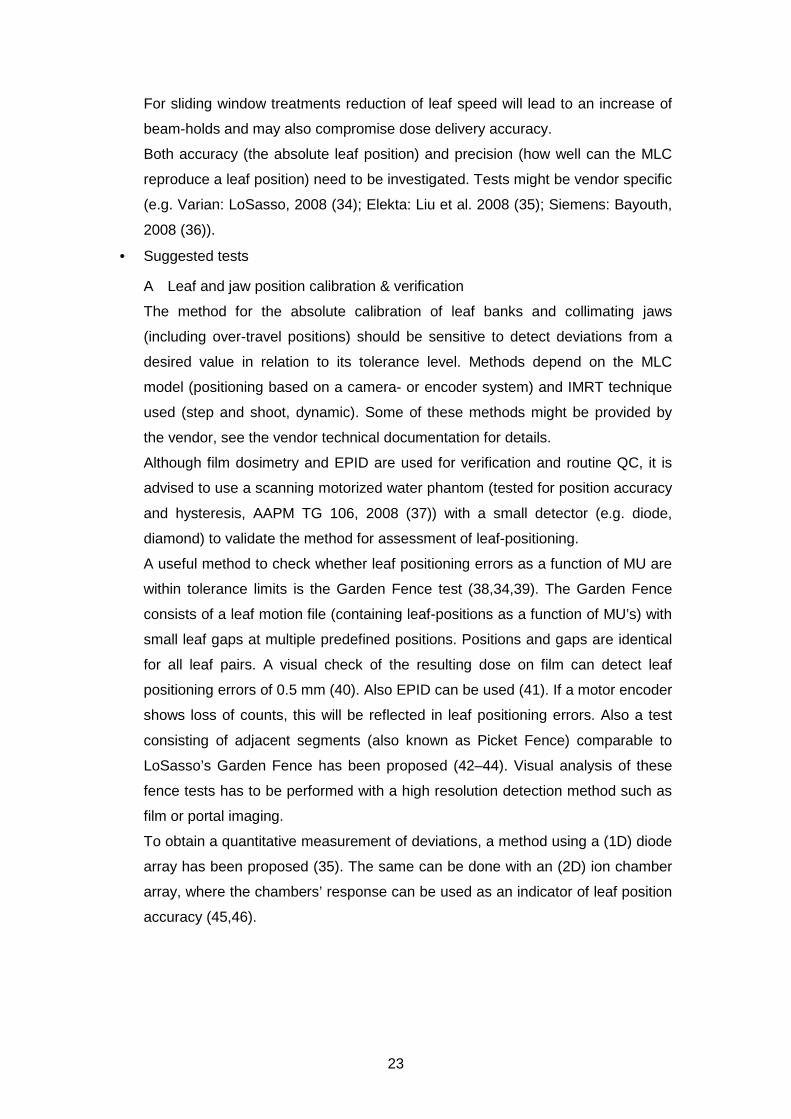
C. Beam profile stability:
The stability of beam profiles (i.e. profile shape) has to be determined at low MU
as a function of gantry angle, also during beam start up.
It is essential that in addition to the proportionality of the dose at the central axis
of the field, the local dose variation has to be kept minimal within all points inside
the beam. Matrices of ion chambers are frequently used for this test, but EPIDs
can also be used for this.
Proposed test: With the use of a linear 1D or 2D detector (array), rigidly mounted
on the linear accelerator head, measure the integrated dose profile (or
corresponding reading) during beam start-up as a function of gantry angle (0, 90,
180, 270; CW and CCW approached) and MU (e.g. 2, 5, 10, 50). Determine for
major axis points (excluding penumbra) the maximum variation of local dose, see
figure 2.1.
Note: Current NCS-8/IEC test is stated for a single point on the CAX with the use
of number of MU equivalent to a dose of 1 Gy.
28
Figure 2.1. Profile stability of a 6 MV 30x30 cm2 field. Left: example of integrated dose of 2 MU for different gantry angles, with the blue marked curve representing the variation in local dose. Right: Variation of local dose (as left figure collected over different gantry angles) for different number of MU.
• Recommended tolerances
As minimum requirement compliance with IEC-60976/60976 (18) is proposed.
The need for tighter tolerances regarding IMRT is achieved as a matter of course,
since conventional tolerances applied to a number of MU corresponding to ~ 1
Gy whereas now criteria apply to the total range. The NCS proposal for desired
requirements is stated below.
• Reproducibility: 0.5%
• Proportionality: 1% (2% if combined with dose rate effect)
• Beam profile stability: 2%
2.4.3. Radiation safety
• Goal
To ascertain that (previously) designed shielding barriers for scattered and
leakage radiation fulfil the intended protection.
• Background
One of the key features of IMRT is the use of non-uniform beam intensities.
Single fields are divided into multiple segments, resulting in a significantly
increase of total number MUs with a factor of two to five (e.g. (55,56,33,57–59)).
As a consequence it should be verified that the shielding design is not
compromised by the increased number of MU’s.
• Suggested tests
29
The shielding calculations should be adapted for the increased number of
monitor units per delivered Gy. This increase of number of MU is reflected by
the so called IMRT factor that accounts for the increase of scattered radiation
from the head of the treatment machine. The IMRT factor is defined as the
ratio of the average number of MU per unit prescribed dose needed for IMRT
and the number of MU per unit dose for conventional treatments. Guidance
can be found in e.g. IPEM Report 75, 1997 (56); NCRP Report 151, 2005 (57)
and IAEA Report 47, 2006 (55). It is advisable to use clinical information to
estimate the increase in leakage dose, i.e. based on a sample of clinical
IMRT cases to calculate the average total MU required. Measurements to
confirm calculations (survey, leakage radiation around the patient, etc.) are
not different for IMRT than for the conventional situation. The evaluation
needs to be repeated if the IMRT factor or workload changes in time.
2.4.4. Small field beam data
• Goal
To acquire PDD’s, beam profiles and output factors for small fields
• Background
IMRT fields contain multiple segments or sliding window apertures that can have
small field sizes. For beam data configuration and/or validation of TPS calculation
accuracy these data have to be acquired for small field sizes.
• Suggested test
A standard water phantom can be used to acquire these data, but the following
practical suggestions for these measurements should be taken into account
(derived from IPEM 103, 2010 (24))
o PDD
One of the problems to be addressed when measuring small field PDDs is
the possible deviation from the beam’s axis with increasing depth. The
result of such a deviation is an underestimation of dose in depth, showing
curves with a steeper fall off. When scanning with a detector too large
with respect to the field size, the PDD will also be affected due to volume
average effects.

30
To measure small field PDDs, preferably diodes should be used with their
axis oriented parallel to the beams axis. Also ionisation chambers with a
volume of about 0.01 cm3 might be used. The preferred scan direction is
from depth towards the surface to reduce the disturbance at small depths.
o Profiles / penumbra
o To measure profiles / penumbras, preferably diodes (both shielded,
unshielded or stereotactic) should be used with its axis parallel to the CAX
of the beam. As an alternative radiochromic film can be used to benefit
from its high spatial resolution provided that a well-defined and proven
film processing protocol is in place.
Since they are not water equivalent and they show penumbra broadening
due to volume averaging, ionisation chambers are not recommended to
measure profiles. But when used, the ionisation chamber’s volume should
be around 0.01 cm3 and without steel electrode.
o Output factors
It is recommended that the total scatter factor Scp in water (defined as the
ratio of dose of a field against the reference: 10x10 cm2 @ d=10 cm) is
measured with multiple ‘suitable’ detectors to estimate the uncertainty in
Scp determination.
A detector should be small enough to measure the smallest field size in
the range clinically used. That makes the use of even the smallest ion
chamber questionable when used without proper response correction.
Shielded diodes may overestimate the output due to fluence perturbation
caused by the high Z shielding. On the other hand the unshielded diode
shows an over response to low energy scattered photons for larger field
sizes. Therefore, an unshielded diode is advised for small field OFs, but a
5x5 cm2 field is preferred as reference field, which in turn can be
measured and related to a 10x10 cm2 reference with an ionisation
chamber.
Regarding the measurement of in-air OF, or head scatter factor Sc, again
diodes are the most suitable detectors for small field measurements. Mini-
phantoms used should be in made of high-Z material, (see (60)).

31
2.4.5. Beam Interruptions
• Goal
To assess the accuracy of a treatment that has had a beam interruption during
treatment delivery.
• Background
IMRT treatments consist of multiple beams with sometimes complex fluence
profiles. After a beam interruption the treatment machine has to continue
treatment with gantry, collimator, MU and MLC-settings at the control point
reached at the time of beam-interruption. Additionally the R&V system must
capture the beam-interruption if the treatment has been closed and must provide
a means to deliver the remaining dose.
• Suggested test
With film, ionization chamber or diode-array a measurement with beam
interruption is compared with measurement without interruptions. This is
performed multiple times at multiple different control points. At each interruption
the treatment should be closed to enable the R&V system to capture the
interruption and deliver the remainder suggested by the R&V system.
• Recommended Tolerance
Tolerance should be within 1% relative to prescribed dose.

32
3. Commissioning a treatment planning system used for IMRT
3.1. Introduction
In NCS 15 (1) practical guidelines for commissioning (initial verification) and QA of a
treatment planning system (TPS) is given, including an exhaustive overview of tests.
However, these guidelines and the presented tolerance levels are restricted to
conformal treatment planning and give no guarantee for an adequate implementation
for IMRT treatment planning.
In this chapter we will give an overview of published tests to evaluate the modelling
accuracy of a treatment planning system for topics specific for IMRT and
supplementary to those tabulated in NCS 15 (1). These topics include the accuracy
of the leaf tip modelling, leaf transmission, modelling off axis beams, modelling of
small beams and abutting fields.
For further reading the AAPM report on IMRT is recommended (61,31).
3.2. Background for the leaf modelling
The dose distribution of a beam, among other design details, depends on the specific
MLC design. Or, vice versa, a specific MLC design is based on dose distribution
demands. For example, most clinically used MLCs are not mounted spherically,
forcing a curved design of the leaf tip in order to achieve similar penumbras for
different positions of the leaf tip (62).
In general, TPS accuracy is assessed by the comparison of measured and modelled
data and tolerances are defined for determined differences. Restricted to conformal
treatment planning, NCS 15 tabulates a tolerance of 2 mm for radiological width,
beam fringe and penumbra region (1) to guarantee appropriate MLC/leaf-tip
modelling. Every TPS uses different parameters related to the MLC design to model
these beam-dose characteristics. In this paragraph we will give an overview of the
most common parameters linked to the MLC design. Of course every user has to
select the relevant parameters for his/her TPS to model his/her linac; for example
leaf tip modelling is only applicable for non-focused MLC designs and tongue and
groove effects are not an issue for MLCs with a tilted leaf bank design.
3.2.1. Leaf tip modelling
In modern treatment planning systems, MLC’s are described separately and several
parameters may be available to model the penumbra resulting from the specific leaf

33
design. Each planning system has its own set of parameters to geometrically
describe the rounded leave tip and accurate, sub-millimetre specification of these
parameters is necessary in order to obtain good dose calculation accuracy in IMRT
(63,61).
Inaccurate modelling of the leaf tip position both on-axis as well as off-axis (35) and
inaccurate modelling of the rounded leaf ends may result in clinically unacceptable
dose differences (47). Therefore, the agreement between the measured and TPS
calculated 50% isodose level and penumbra width should be within 1mm. Special
attention should be given to 50% isodose level agreement for the small field sizes.
A rounded leaf tip design implies an offset of the radiological position of the leaf tip
relative to the projected light field position of the leaf at isocentre distance (64,46).
This offset is a function of the leaf tip position (65). The leaf tip position offset is a
geometric parameter to model this offset.
3.2.2. Match-lines or abutting fields for the evaluation of the rounded leaf tip
modelling
Step and shoot irradiation techniques are most sensitive to errors in the leaf tip
modelling especially for abutting fields. Small errors result in relatively large dose
errors at the field abutment. Methods/Measurement applying abutting fields in order
to evaluate several independent modelling parameters are described in the literature
(66,40,28). To evaluate the rounded leaf tip modelling, the dose at the matching field
boundaries calculated by the TPS is compared with the dose measured using
radiographic and/or radiochromic films. An alternative method using small gaps
between the fields has been reported as well (44,67).
3.2.3. Leaf gap modelling
In order to compute the dose more accurately, especially for small leaf gaps (67)
used for dynamic IMRT techniques, LoSasso et al. (47) introduced an alternative to
model the dosimetric effects of a rounded leaf tip. This parameter is called the
Dosimetric Leaf Separation factor (DLS) or Dosimetric Leaf Gap (DLG). It accounts
for the transmission through the round edge of both opposing leaf tips of the moving

34
leaf gap. The quantity is an offset added to the nominal leaf gap and it ensures dose
computation accuracy especially for small gaps.
3.2.4. Dose Transmission through the MLC
Dose transmission through the MLC has two main components, leaf transmission
and interleaf leakage. The former is determined by the geometrical height (and
material) of the leaf. The latter is determined by the space between the leaves
necessary for (frictionless) motion but, by design, is reduced either by tilting the MLC
(68) or by the tongue and groove of each leave.
3.2.4.1. Tongue and groove effect
It has been shown that when a single leaf is exposed to a radiation field, the actual
leaf blocking, perpendicular to leaf-motion, is larger, e.g. 1.1 cm for a 1.0 cm leaf at
the isocentre, resulting in a smaller full width half maximum for the MLC-defined field
compared to a jaw-defined field (51,35,67). Several treatment planning systems allow
the introduction of a value concerning the tongue and groove effect resulting in a
significant reduction of the dose calculation error. Separate MLC defined fields are
often measured for the determination of this tongue and groove value (65).
3.2.4.2. Interleaf leakage and leaf transmission
The composite radiation transmission by the MLC is determined by leaf transmission,
the additional interleaf transmission and the aforementioned tongue width. Most
treatment planning systems are not able to account for these properties separately.
Either a single value can be introduced taking into account for the average effect of
interleaf leakage and leaf transmission or two separate values (65). Using
GafChromic film measurements interleaf leakage and leaf transmission values can
be determined separately. Using a large ionization chamber oriented orthogonal to
the leaf direction the sum of both values is registered. For both film measurements
and chamber measurements leaf-only fields with matching leaf tips underneath the
Jaws are recommended. For IMRT treatments, both SS and SW, the dose at a
certain position is a combination of the dose of open IMRT segments and the
contribution due to the composite MLC transmission. As a result, especially for the
low dose regions, the dose contribution of interleaf leakage and leaf transmission can
be several times higher in IMRT as compared to 3D conformal radiotherapy. As a

35
consequence tighter tolerance values have to be set for the modelling of the low-
dose regions compared to NCS 15 (1).
3.3. Recommendations for leaf modelling
The following tests are recommended:
3.3.1. Leaf tip modelling
Verification of the leaf tip modelling (penumbra) for several leaf positions is
recommended, keeping in mind that each MLC design has its own characteristics
and that dosimetric consequences of leaf tip modelling accuracy also depends on the
delivery technique (e.g. SS versus SW). Because of the required positional resolution
diodes, diamond or liquid-filled ionisation chambers, film dosimetry and EPIDs are
the recommended measurement devices. A sub-millimetre agreement of the 50%
dose position is recommended. The TPS calculated dose profiles of an IMRT field
consisting of several small (elongated) field-segments (width 1 cm) are compared
with measured profiles. The small field-segments are located at different off-axis
positions either in an abutting setting or with small gaps (1 cm) in between
(36,31,65). Agreement should be within 5-10 % of dose maximum.
Proposed leaf positions (leaf bank1/leaf bank 2 [cm]) for the small fields with gaps:
segment 1) 10.5/-9,5
segment 2) 8.5/-7.5
segment 3) 6.5/-5.5
segment 4) 4.5/-3.5
segment 5) 2.5/-1.5
segment 6) 0.5/0.5
segment 7) -1.5/2.5
segment 8) -3.5/4.5
segment 9) -5.5/6.5
segment 10) -7.5/8.5
segment 11) -9.5/10.5
Also see figure 3.1. Jaw positions should be at least 5 cm out of leaf boundaries.

36
Figure 3.1 Example of the dose distribution for evaluation of the leaf tip modelling using small fields with gaps (the central plane is located at distance 12 cm at the centre of segment 6).
Proposed leaf positions (leaf bank1/leaf bank 2 [cm]) for the small abutting fields:
segment 1) 10/-8
segment 2) 8/-6
segment 3) 6/-4
segment 4) 4/-2
segment 5) 2/0
segment 6) 0/2
segment 7) -2/4
segment 8) -4/6
segment 9) -6/8
segment 10) -8/10
Also see figure 3.2. Jaw positions should be at least 5 cm out of leaf boundaries.

37
Figure 3.2: Example of the dose distribution for evaluation of the leaf tip modelling using abutting fields (the central plane is located at distance 11 cm, in between segment 5 and 6).
3.3.2. Leaf position modelling
We recommend using an abutting field set-up in order to verify the leaf positioning
modelling: perfect matched fields and small gaps/overlaps are planned in the
treatment planning system and compared with film measurements. An example of
such an abutting field set-up is shown in figure 3.3. When using small segment IMRT
irradiation fields, a field-position (defined by 50% dose) agreement tolerance of 0.5
mm or better is advised.
Figure 3.3 Example of non-perfect matched fields used for verification of the treatment planning system (69).
38
3.3.3. Dosimetric Leaf gap modelling
In section 2.4.1.2-C the method for determining the dosimetric leaf gap has been
described.
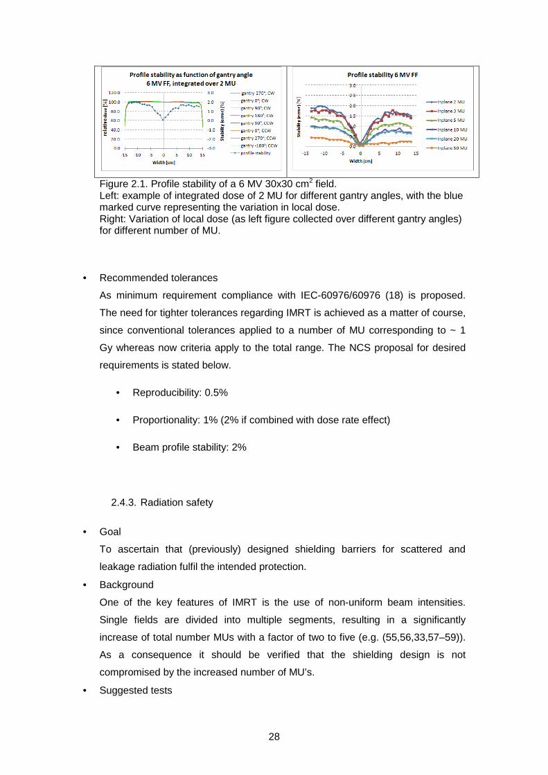
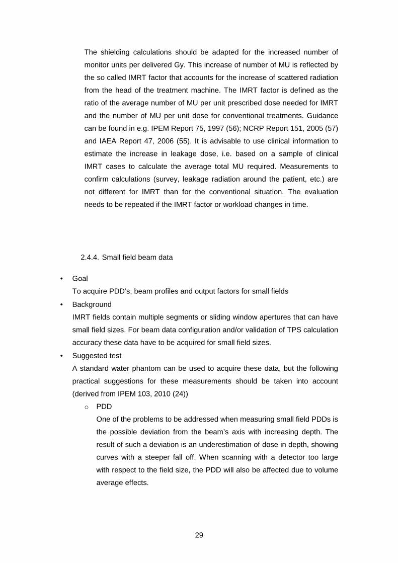
3.3.4. Tongue and groove effect
Accurate modelling of this effect can be evaluated by adding half fields orthogonal to
the leaf direction and compare TPS results with film dosimetry or by measuring the
FWHM of narrow MLC determined fields with the jaws retracted. Fields determined
by, for example, three retracted leaves will result in a field size of for instance 2.8 cm
instead of 3 cm nominal field size at reference depth (62). Inappropriate modelling of
this effect can result in dosimetric errors as illustrated in figure 3.4b when leaves are
moving asynchronously (sliding window IMRT) or when large differences in leaf
position are generated for adjacent leaves (step and shoot IMRT).
Figure 3.4a Example of MLC fields for determination of the Tongue and Groove Value (69).
Figure 3.4 b Example of a field with a tongue and groove effect dose discrepancy.

39
The dosimetric consequences of the tongue and groove effect can be reduced by
selecting appropriate collimator angles and/or segments. This can be evaluated for
each class solution.
3.3.5. Interleaf leakage and leaf transmission
The required accuracy for the transmission modelling is dependent on the treatment
technique used. The modulation scaling factor (MSF; total amount of MU/amount of
MU for open conformal beams) determines the required tolerance (70). We advise to
divide the 50% tolerance level for 3D conformal techniques (NCS 15 (1)) by the MSF
in order to obtain the required tolerance for the treatment planning system. A
tolerance of 10% between calculated and measured values is the state of the art
value recommended by NCS. An average of interleaf leakage and leaf transmission
can be obtained by averaging radiochromic film readings or using large ionisation
chamber readings (farmer type). Detector systems that are energy dependent should
be avoided (e.g. radiographic films) since the energy spectrum of the leaked radiation
differs from the open beam energy spectrum.
If interleaf leakage and leaf transmission can be modelled separately in the TPS,
radiochromic film measurements are recommended to discriminate between leakage
and transmission and to obtaining accurate results., When measuring MLC leakage
and transmission, note that the collimating jaw or backup-jaw, if present, is retracted
at least 5 cm. Apply the same 5 cm retraction for the MLC leaf banks when
measuring jaw transmission. In order to avoid influence of scattered dose at the leaf
tips, a difference of 5 cm between the leaf tips and the measuring points is advised.
3.4. Dose calculations outside field edges
3.4.1. General Remarks
The prediction of dose transmitted through MLC, backup-jaws and collimating jaws,
i.e. outside the geometrical edges of IMRT segments, was recognized to be of great
difficulty (71). Relative differences of up to 50% between measurement and
calculated dose are reported. This is equal to the tolerance for the commissioning of
a treatment planning system for 3D conformal radiotherapy. For IMRT treatments the
contribution of dose transmitted through MLC and (backup-) jaws and consequently a
tolerance for TPS accuracy is linked to the degree of modulation and the number of
40
segments (72). A similar tolerance level 50%/MSF as for the leaf transmission is
recommended (see also paragraph 3.3.5). Several studies have been published
linking the IMRT optimization process to the predicted dose on PTV/OAR on a
planning study level, where optimization processes are advised that reduce MU’s and
dose outside the PTV (73–75). For Elekta machines with a standard MLC (40 leaf
pairs of 1 cm leaf width at isocentre, no over-travelling collimator jaws, MLCi &
MLCi2) an additional effect of dose calculation outside the field boundaries should be
taken into account. As reported in the literature (76,77), a field/segment with an
elongated open MLC part blocked by the backup-jaw can occur to define an over-
travelled field (‘flagpole’). A 10% transmission through the backup jaws is described
and an accurate modelling of this transmission dose outside the field boundary is
necessary.
3.4.2. Recommendations
The dose at several distances outside the edges of an individual segment should be
evaluated (e.g. 2,5,10 cm). An IMRT beam with a fluence pattern like an inverse
pyramid (78,79) provides a pyramid like dose distribution suitable for verification of
the TPS calculated dose outside segment edges: for each step on the dose pyramid
(beamlet) the TPS calculated dose can be verified by an ionisation chamber
measurement. This can be done by defining the inverse pyramid fluence pattern by
fixed jaws, closing in jaws and step and shoot or sliding window delivery techniques.
For Elekta machines the transmission through the “backup” jaws has to be verified in
case fields with a ‘flagpole’ have to be introduced to define an over-travelled field.
Examples of ‘flagpole’ fields are reported in literature and a similar tolerance level is
recommended as for the leaf transmission tolerance (see paragraph 3.3.5.).
3.5. Modelling of Small Fields
3.5.1. General Remarks
IMRT delivery techniques are generally using segments (both in step and shoot and
sliding window techniques) with limited field sizes, even small fields. Small fields are
defined as fields that do not exhibit lateral electronic equilibrium in the centre of the
beam (80,24). If the selected treatment delivery system applies such segments, one
must pay extra attention before implementing IMRT.

41
The following effects play a role in the dosimetry off small fields (< 3x3 cm²).
• As the beam shape is made smaller, the total photon energy spectrum shifts
to a spectrum determined by the thickness of the flattening filter (22,26)
• The photon fluence will decrease with smaller fields due to the partial
covering of the effective spot size (81)
• The photon fluence will decrease with smaller fields due to the scattering in
the flattening filter (81)
3.5.2. Recommendations
First off all, the smallest allowable IMRT segment/leaf-gap should be assessed.
Output factors and depth dose curves of this field should be measured to verify that
the treatment planning system is able to predict the data within 5% (2x2cm² or 3x3
cm² field sizes). An appropriate calculation grid size for dose calculation is advised
and special attention should be given to the shape of the depth dose curves for each
clinically used grid size. A general remark is the use of the appropriate grid size for
the modelling of small segments/leaf-gaps. The grid size should be finer than the size
of the beams/segments/leaf-gaps (31).
3.6. The modelling of bi-directional off-axis beams
3.6.1. General Remarks
In the IAEA-TECDOC 1540 (82) and NCS-15 (1) asymmetric half beams are
suggested for the QA program of general Treatment Planning Systems. IMRT
treatment plans may use smaller segments/leaf-gaps which may be positioned
extremely off axis. Therefore, in addition to NCS-15 recommendations one should
perform tests using such small, extremely off-axis fields. The tolerance criteria of the
dose prediction should however be adapted to the complexity of the dose calculation
as has been described in literature (71). The selected field size should be linked to
the clinically used dimensions and if smaller then 3x3cm² one must be aware that the
beam quality variation in off-axis direction due to the flattening filters adds an
additional pitfall for small field modelling (83).
3.6.2. Recommendations
NCS suggests verifying asymmetric half and quarter beams. For IMRT treatment
plan verification in plane and cross plane over-travelled fields should be verified
42
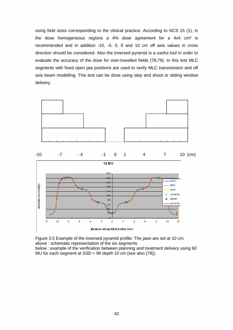
using field sizes corresponding to the clinical practice. According to NCS 15 (1), in
the dose homogeneous regions a 4% dose agreement for a 4x4 cm² is
recommended and in addition -10, -5, 0, 5 and 10 cm off axis values in cross
direction should be considered. Also the inversed pyramid is a useful tool in order to
evaluate the accuracy of the dose for over-travelled fields (78,79). In this test MLC
segments with fixed open jaw positions are used to verify MLC transmission and off
axis beam modelling. This test can be done using step and shoot or sliding window
delivery.
-10 -7 - 4 -1 0 1 4 7 10 (cm)
Figure 3.5 Example of the inversed pyramid profile: The jaws are set at 10 cm. above : schematic representation of the six segments. below : example of the verification between planning and treatment delivery using 60 MU for each segment at SSD = 90 depth 10 cm (see also (78)).
43
3.7. Verification of TPS in inhomogeneous phantoms (calculation algorithms)
3.7.1. General Remarks
Heterogeneity corrections may be more important for IMRT than for conventional
treatments, for several reasons (31). IMRT treatments often incorporate more and
different beam directions than are used conventionally, so previous clinical
experience with uncorrected doses may not translate well.
This implies a careful reconsideration of the calculation algorithms for each tumour
site. Especially for low density dose prediction Monte Carlo (MC) based, Collapsed
Cone Convolution (CCC) or Anisotropic Analytic (AAA) based algorithms are advised
in order to obtain accurate dose predictions (84–89). For smaller segments/leaf-gaps
larger differences in heterogeneous media are found (84,88). In relation to IMRT
special attention on the accuracy of the treatment planning system should be given.
One should notice that the inverse optimization algorithm frequently use a simple
heterogeneity algorithm. Discrepancies between optimizer dose distributions and full
computation dose distributions should be assessed.
3.7.2. Recommendations
NCS-15 (1) proposes some tests on inhomogeneous phantoms for 3D conformal
treatments. Large fields are verified on a phantom with a low density insert. In
addition to NCS-15, this NCS report recommends the verification in the same or
similar phantom using a small or narrow field (e.g. 2x2 cm²; 16x2 cm² (90)). In the
literature similar testing is reported for IMRT beam deliveries (84,91,92). Testing can
be done using solid phantoms with air and cork inclusions or anthropomorphic
phantoms. Extensive testing is not advised while the accuracy is mostly determined
by the algorithm and this can be found in literature (84–89). Furthermore, dose
verification at interfaces is difficult to perform.
3.8. Verification of the optimization algorithm
3.8.1. General Remarks
Several forward and inverse optimization strategies are clinically used to create an
optimal dose distribution. These methods may use direct aperture optimization or
multi criteria optimization (Pareto Optimization). Optimal dose distributions are

44
obtained using either physical or biological cost functions. The optimum of such cost
functions defines the optimal dose distribution in a deterministic or stochastic manner
for both the planning target volumes (PTV) and the organs at risk (OAR), with or
without simultaneous integrated boost dose levels. Several good review articles are
available in the literature (91,31,93).
3.8.2. Recommendations
A general remark on the recommendations for optimisation algorithms is the use of
the appropriate grid size. IMRT is often used in situations with high dose gradients.
The grid size should be finer than the size of the segments used and such that
modulations in the incident fluence map are adequately sampled (31).
In order to evaluate and to compare all those optimization and treatment delivery
techniques several authors propose inter-centre quality assurance solutions using
common plan objectives on well-defined volumes (PTV and OAR) (20,91,61,10,94).
The Quasimodo results are a good benchmark while a large set of different planning
systems are compared providing good reference values to evaluate the planning
system and optimizer of each centre.
3.9. Systematic sequence of the commissioning of an IMRT planning system
3.9.1. General Remarks
Ezzell et al. (31) recommend a workflow in which the dosimetric commissioning of an
IMRT planning system should follow a systematic sequence. Many of the tests in this
sequence require that the system allows the user to specify a desired intensity
pattern and apply it to a phantom so that the resulting doses can be measured and
confirmed. The basic scheme is to advance from simple to more complex tests. For
example, start with a single beam on a simple, flat (i.e. geometric) phantom with
controlled intensity patterns. When those are evaluated, then progress using
controlled intensity patterns for multiple beams on the simple phantom. After that,
apply multiple beams treating hypothetical targets in the flat phantom. Finally (if
possible) progress testing multiple beams treating hypothetical targets in
anthropomorphic phantoms. The goals are, first, to determine if the beam parameters

45
are accurate using simple situations that are easy to evaluate and, second, to
determine the level of accuracy to expect in clinical situations.
3.9.2. Dosimetric Verification
Generally it is accepted that a good agreement between planned dose and delivered
dose is obtained when the dose difference in homogeneous dose regions is within a
well-defined margin (2-3 % of the prescription dose) while in regions with doses with
steep dose gradients (> 30%/cm) the distance to agreement (DTA) should be better
than 4 mm (95). These combined criteria are merged by using the definition of the
gamma evaluation index (96). It should be notified that this model should be
considered with some care regarding the evaluation dimension of the gamma
criterion (1D/2D/3D) and some minor improvements have been proposed later to
optimize the gamma evaluation criteria (97).
The exact tolerance levels depend on the measuring devices used, varying form 2%
to 7.5% for the dose levels and varying from 2 mm to 5 mm for the DTA
(98,99,92,48).
The DTA is influenced by the spatial resolution of the measuring device and the
calculation grid of the TPS, the exact dose tolerance level can be determined by
performing an error analysis of your measuring device, treatment planning system
(see references above).
For 2D evaluations, a 3% / 3 mm agreement for 90-95% of the data points is
considered to be state of the art (61), often achieved by combining spatial accurate
film dosimetry normalised to a region of homogeneous dose using an ionisation
chamber reading. Systems with less accurate spatial resolution can, depending on
delivery technique, result in differences in the obtained gamma value and as a
consequence a different passing rate (63). This implies a critical evaluation of the
acceptance threshold values/criteria. Additionally, some remarks about the predictive
power of the gamma value have been published although those remarks are limited
to planar dose measurements (100,101). One of the evident shortcomings is the lack
of spatial information since this is impossible in a single numerical value. This can be
resolved by profile analysis at clinically critical regions of interest.
The user should consider carefully what percentage γ<1 and averaged gamma value
is acceptable, considering the measuring technique. For example, changing from 2D
to 3D evaluations may lead to a considerable increase in number of evaluated points
and possibly smaller distances to agreement. Evaluating more points, especially in
regions with little dose modulation may mask erroneous regions if the acceptable

46
percentage γ<1 is set too low. Therefore, although 3D evaluation is preferred over 2D
evaluations, the passing criterions may need to be stricter.

47
4. Patient Specific QA
4.1. Introduction
Once the entire chain of treatment planning system, data transfer and treatment
delivery has been commissioned, one needs to ensure that 1) appropriate treatment
plans are made for a specific patient, 2) that these plans are transferred correctly to
the linac and finally 3) that they are delivered accurately. In this chapter, we describe
the equipment needed for proper patient-specific QA, the steps required for
developing a class solution, introducing this new class solution in the clinic and
performing QA for existing class solutions using either pre-treatment or in-vivo
checks. The QA demands depend on the institute’s experience with IMRT and the
complexity of the technique. If deviations beyond accepted limits occur between
predicted and measured values, an expert (medical physicist) has to be consulted
and the problem has to be investigated.
4.2. Definitions used in patient-specific QA
The different methods for QA are assigned to different classes where the highest
class (I) has the lowest number. For this purpose, we made a distinction between
dosimetric accuracy and spatial resolution since both play an important role in IMRT-
QA. In practice, different tools may be combined to achieve optimal dosimetric and
spatial resolution.
Unless stated otherwise we define:
• A low gradient region is a region in which the dose varies less than 20% per
cm, compared to the local dose value.
• A spatial resolution of 2 mm or better is considered ‘high-resolution’ and as
such falls into the class I devices regarding spatial resolution.
• The reference dose is the dose prescribed to the relevant target volume
(PTV). If elective target volumes are present with substantially different dose
levels, the prescribed dose to these regions should be used as reference
dose for those volumes. It might be necessary to run the gamma analysis
multiple times with different reference doses.
48
• The phantoms used for pre-treatment verification should preferably be the
same size as the treatment site under consideration. Thus, for head and neck
IMRT a different phantom should be used compared to prostate IMRT.
4.3. Gamma analysis
We recommend performing a gamma evaluation with a criterion of at least 3%/3mm
(96,102), if possible using absolute dosimetry. For a 2D and 3D evaluation all
measured points with a dose below 10% of the reference dose should be discarded
to avoid false positives due to low signal-to-noise in the low dose area. The choice of
the actual cut-off value is at the discretion of the user, in part based on the treatment
site, the equipment used and the choice between a 2D and 3D gamma evaluation.
The maximum allowed deviation of gamma>1 is 10% of the points sampled. If the
averaged Γ-value is above 0.5, an expert (medical physicist) should look into the
problem. See e.g. Stock (102) for directions how to interpret gamma images and
section 3.9.2 for additional remarks on the use and predictive power of the gamma
evaluation.
To achieve a distance to agreement (DTA) of 3 mm or better it is recommended to
perform the dose computation with a resolution of 3 mm or better, depending on
computation times. The slice thickness of the imaging dataset used for dose
computation should be considered to meet this criterion.
For the gamma evaluation, it may be necessary to normalise the measured dose
distribution to the computed one and register them. Both registration matrix and
normalisation constants should be monitored and should not deviate substantially
more than the stated gamma criteria (DTA/dose) from their expected values.
Finally, all equipment used should be calibrated properly and their limitations in terms
of dosimetric and spatial accuracy/precision should be known and taken into
consideration. As stated in section 3.9.2, the gamma evaluation tool should be
considered with care and should not be used as the only evaluation criterion
(100,101).
4.4. Validation of plan transfer
For IMRT it is impractical to perform a manual check for al treatment parameters to
ensure correct transfer of the final plan to the linac. Although cross-check as
suggested in table 4.1 are highly recommended, not all parameters can be checked

49
in this way. Therefore we suggest to perform a thorough plan transfer check for 50
patient plans to assess correct transfer. If the final plan can be altered at the linac,
procedures to prevent accidental changes should be implemented. An automated
procedure to check the consistency between intended plan and the plan at the
Record and Verify System is highly desirable.
4.5. Methods
Below we summarise several systems that can be used for IMRT-QA. We briefly
reflect on the advantages and disadvantages of the various systems.
4.5.1. High-resolution evaluations
Film measurements
Film is traditionally used for the (pre-treatment) verification of fluences and integral
dose distributions produced by linacs. In the past, radiochromic films were
successfully used to perform gamma analysis with a 3%/3mm gamma criterion (103).
In 2011/2012, this type of film is being replaced by EBT/GafChromic films which have
some problems because of the inhomogeneous distribution of its active component.
In 2011, EBT/GafChromic films can be applied for gamma evaluation with 5%/3mm
(104). The user is advised to update his/her knowledge with respect to the present
capabilities of film dosimetry. Films are used for relative dose measurements, but can
also be used for absolute measurements if both films and scanner are calibrated
properly. Care must be taken to establish a dose-density curve per batch of film
because of the known differences in sensitivity between batches of films.
Film can be used for visual inspection even if dosimetric accuracy is low. With visual
inspection, one can determine tongue and groove effects, abutting leaf problems and
the effect of flagpoles. Such findings may be cause for reconsideration of the linac
parameters or IMRT class solution.
EPID Measurements
Electronic Portal Imaging Devices (EPIDs) can be used to replace film dosimetry for
transit dosimetry and pre-treatment fluence verification without a phantom in the
beam. There are various advantages of EPID dosimetry over film dosimetry:
o Instantaneous imaging: no developing or digitizing of films needed. This
allows fully automated generation of dose images and gamma maps and

50
evaluation. This infrastructure enables the development of 3D in vivo
reconstructive dosimetry in combination with a cone beam CT scanner on the
linac (105–108)
o The imaging can be time-resolved; i.e. imaging of separate segments in a
sequence is possible
o It can be used at any gantry angle
o EPID calibration is less time consuming compared to per-batch film
calibration
o In many institutes, linacs are equipped with an EPID
There are some disadvantages however:
o At present (2013), existing commercial EPID dosimetry systems are rather
primitive and do not make use of the full potential of EPID dosimetry.
o Proper calibration of the EPID for dosimetry requires expert knowledge, which
is now not readily (commercially) available. For example, the backscatter of
the EPID suspension arm influences the acquired images. Furthermore, the
implementation of full 3D EPID in vivo dosimetry is implemented in only a few
institutes worldwide.
o Limited field of view: typically around 25 cm at isocentre. For mirror-based
EPIDs, this means that parts of large fields cannot be imaged; for (ASi) flat
panel based imagers this means that larger fields need to be modified before
verification, which is not desirable. Some (parts of) fields can still be imaged
by applying off-axis shifts of the detector or by reducing the source-to-
detector distance.
o The EPID cannot be placed inside a phantom/patient.
o Effects of Gantry sagging are not (directly) included in the measurements.
o In flat panel detectors, the EPID electronics may deteriorate due to heavy
usage and its life-time may be decreased compared to regular use. Imaging
complete treatment beams for dosimetry purposes is a greater burden to the
imager than only using it for setup images.
4.5.2. High dosimetric accuracy evaluations
Ionisation chambers are the gold standard for absolute dose measurements (2).
However, for small fields other detectors may be better suited, each with their
limitations (see section 2.2)
51
To evaluate the dose distribution at multiple points, several devices are commercially
available consisting of a phantom with multiple diodes/ionisation chambers. As is
possible with EPIDs, some of these systems are capable of reconstructing measured
dose into a 3D dose distribution in a patient geometry. This is in particular true if the
3D distribution of the measurement chambers has been chosen in a clever way. As
an advantage, gamma evaluations can be correlated to dose differences in clinical
regions of interest and effects on DVH changes.
Note: TLD or MOSFET measurements are not recommended because of the low
accuracy and high processing time. If point measurements are considered, ion
chamber or single diode measurements are preferred because of higher accuracy.
TLD or MOSFET measurements might be suitable for measuring entrance dose in
vivo, for example near the eye.
4.5.3. General checks on plan
4.2.3.1 Plan transfer check
The goal is to ascertain that the intended plan has been selected and correctly been
transferred to the linac, i.e. the Record and Verify System. This may be done by
manually or automatically comparing the number of MU per segment, segment
shapes et cetera, but one should acknowledge that manual checks have a limited
value. A fully automated system, comparing all items would be desirable.
4.2.3.2 Monitor unit check
The primary goal of a monitor unit check (MU check) is to serve as an independent
plausibility check of the treatment plan. MU check procedures come in different
versions:
1. Ionization chamber measurement: A measurement in a well-defined, low-
gradient point can serve to check the plan. This approach has the advantage
of actually checking physical dose at the end of the transfer chain, but suffers
from the disadvantage of being labour intensive. Additionally, errors may be
detected only late in the process, possibly leading to extra work Obviously,
the dose distribution has to be recomputed for the phantom geometry, using
the clinically intended linac settings.
2. Complex, multi-segment computations
o Commercial software: Some companies offer software packages for
performing MU checks. The advantage is that an institute does not
need to develop an MU check themselves and may benefit from the

52
experience from other users. As with all medical software, proper
commissioning of such a package is mandatory. It may be difficult to
integrate commercial packages seamlessly into the existing workflow.
o In-house developed software: This offers the possibility to tailor the
MU check to the local work flow. Not all institutes may have the
resources to develop in house software. Care must be taken to
carefully check the code, preferably also by an independent party. As
with all in-house developed software for the medical domain, the code
must be carefully documented and tested. An example of an algorithm
that can be implemented for an MU check was published by Baker
(109) or Georg (110).
o For all checks action levels should be defined above which the
medical physicist should be consulted.
3. MU range-based. For each class solution, an empirical relation is established
between the prescribed dose and the total number of monitor units applied,
considering shape, size and weight of the individual segments. If the number
of monitor units is outside a certain range, action is requested. The range
may be defined such that 10% of all plans are presented for evaluation. The
empirical relation may be established after 30 treatment plans. This type of
check can only be used as an early warning and should be combined with
more thorough checks later in the chain, pre-treatment or in-vivo. This method
uses a trade-off between detection of errors and false negatives (therefore
workload). The action level may be adjusted according to clinical experience.
4. Table based dose calculation: based on knowledge of or availability of
tabulated depth-dose curves and output factors. This method works as a
plausibility check for straightforward conformal plans but is not adequate for
IMRT plans where the number of monitor units is not correlated directly to the
dose in a chosen point.
5. Finally, a visual comparison of the plan may be carried out on both the
treatment planning system and the Record and Verify System connected to
the linac. It should be noted that with this only a rather crude check of the
plan is performed. The shape of the MLC segments cannot be compared
accurately with the intended shapes. This type of check can only be used as
an early warning and should be combined with more thorough checks later in
the chain, such as in-vivo dosimetry. Using visual inspection, also segments
with a small equivalent size and/or few MU’s can be identified.

53
Recommendations:
o Use an (automated) MU check procedure, properly commissioned and if
possible validated by a third party.
o Calculate the (automated) MU check using the final export of the intended
plan to the linac, which usually is a DICOM (rtplan) object. This should also
check that the transferred plan is indeed the intended plan.
o The maximum allowed difference between the dose calculated by the MU
check and the planning system is 5%. The point in which the dose is
compared must be in an area with a low dose gradient and must be between
80% and 120% of the reference dose.
o It is not necessary to have a second planning system serving as an MU check
to double check the primary planning system.
o While implementing an MU check it may also be worthwhile to implement a
‘weirdness’ check which looks at unusual segments, such as very small
segments (<1 cm2) with many MU’s, segments with few MU’s (<4) or
segments outside the PTV or the patient.
Additionally, if the MU check is not performed on the plan stored in the Record en
Verify database on the linac, a plan transfer should be performed for all patients
(Table 4.1, level IV check). Additionally, if the EMR allows changes to the IMRT plan,
automated systematic checks on unwanted modifications are highly recommended.
4.5.4. Summary of QA methods
The different means for patient-specific QA are summarized in table 4.1. In our view,
high spatial resolution is considered an important aspect for (patient-specific) IMRT
QA, more important than, e.g., 3D reconstructed dose distributions, given the current
possibilities of the available hard- and software.
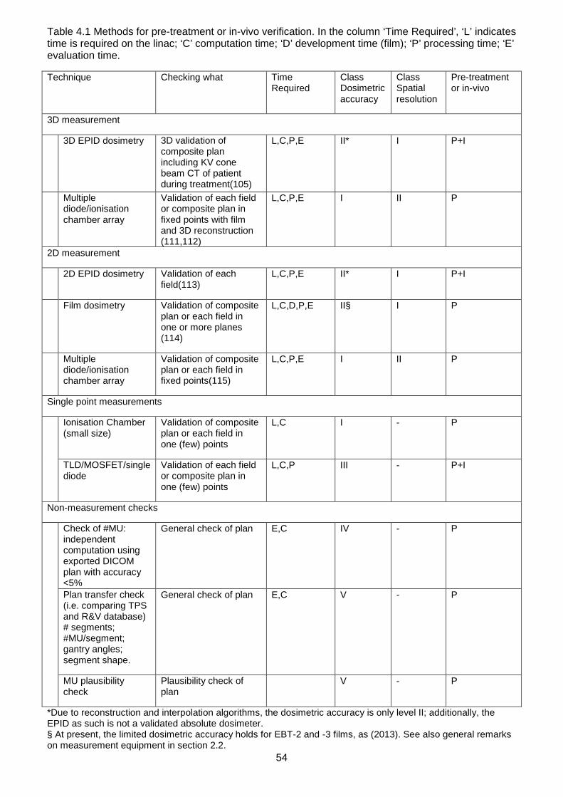
54
Table 4.1 Methods for pre-treatment or in-vivo verification. In the column ‘Time Required’, ‘L’ indicates time is required on the linac; ‘C’ computation time; ‘D’ development time (film); ‘P’ processing time; ‘E’ evaluation time.
Technique Checking what Time Required
Class Dosimetric accuracy
Class Spatial resolution
Pre-treatment or in-vivo
3D measurement
3D EPID dosimetry 3D validation of composite plan including KV cone beam CT of patient during treatment(105)
L,C,P,E II* I P+I
Multiple diode/ionisation chamber array
Validation of each field or composite plan in fixed points with film and 3D reconstruction (111,112)
L,C,P,E I II P
2D measurement
2D EPID dosimetry Validation of each field(113)
L,C,P,E II* I P+I
Film dosimetry Validation of composite plan or each field in one or more planes (114)
L,C,D,P,E II§ I P
Multiple diode/ionisation chamber array
Validation of composite plan or each field in fixed points(115)
L,C,P,E I II P
Single point measurements
Ionisation Chamber (small size)
Validation of composite plan or each field in one (few) points
L,C I - P
TLD/MOSFET/single diode
Validation of each field or composite plan in one (few) points
L,C,P III - P+I
Non-measurement checks
Check of #MU: independent computation using exported DICOM plan with accuracy <5%
General check of plan E,C IV - P
Plan transfer check (i.e. comparing TPS and R&V database) # segments; #MU/segment; gantry angles; segment shape.
General check of plan E,C V - P
MU plausibility check
Plausibility check of plan
V - P
*Due to reconstruction and interpolation algorithms, the dosimetric accuracy is only level II; additionally, the EPID as such is not a validated absolute dosimeter. § At present, the limited dosimetric accuracy holds for EBT-2 and -3 films, as (2013). See also general remarks on measurement equipment in section 2.2.

55
At present, it is difficult to obtain a system that combines high dosimetric accuracy
with a high spatial resolution. EPID dosimetry is not yet widely available and film
dosimetry is at present (2013) changing rapidly. If the institute is not equipped to
perform film dosimetry, they are advised to contact institutes that can help them with
this. Other high-resolution dosimetry equipment such as liquid-filled ionisation
chambers may become available as an alternative to film measurements.
4.6. Development of class solutions
For every common treatment site, a class solution needs to be defined, helping to
ensure that an IMRT plan has stable quality, predictable properties and minimal
variations between planners. A properly defined class solution is the basis of a
controllable QA flow.
If another institute has already developed a similar class solution, it is highly
recommended to pay a multi-disciplinary (physicist, Radiotherapy Technologist
(RTT), physician) visit to the more experienced institute to prevent reinventing the
wheel and thereby shortening the learning curve. This is in particular useful if the
institutes have a similar planning system and linac.
For the establishment of a class solution several conditions need to be fulfilled:
• Prerequisites:
o The treatment planning system has to be commissioned for the type of
IMRT that will be used in the class solution, e.g.: sliding window
versus step and shoot close-in technique. The limitations of the TPS
have to be known and accounted for in the development of the class
solution.
• Up-front input:
o A set of physical parameters that define planning of the class solution.
These may include gantry and collimator angles, beam energies,
maximum number of monitor units for the composite plan, for SS
minimum number of monitor units per segment, minimum segment
size, maximum number of intensity levels and for SW maximum
gradient in fluence and minimum size of peaks.
o A definition of the anatomical structures involved, as well as a protocol
for delineation including imaging modalities and window/level settings
to be used.
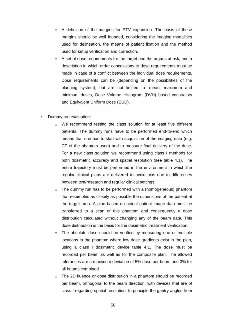
56
o A definition of the margins for PTV expansion. The basis of these
margins should be well founded, considering the imaging modalities
used for delineation, the means of patient fixation and the method
used for setup verification and correction.
o A set of dose requirements for the target and the organs at risk, and a
description in which order concessions to dose requirements must be
made in case of a conflict between the individual dose requirements.
Dose requirements can be (depending on the possibilities of the
planning system), but are not limited to: mean, maximum and
minimum doses, Dose Volume Histogram (DVH) based constraints
and Equivalent Uniform Dose (EUD).
• Dummy run evaluation:
o We recommend testing the class solution for at least five different
patients. The dummy runs have to be performed end-to-end which
means that one has to start with acquisition of the imaging data (e.g.
CT of the phantom used) and to measure final delivery of the dose.
For a new class solution we recommend using class I methods for
both dosimetric accuracy and spatial resolution (see table 4.1). The
entire trajectory must be performed in the environment in which the
regular clinical plans are delivered to avoid bias due to differences
between test/research and regular clinical settings.
o The dummy run has to be performed with a (homogeneous) phantom
that resembles as closely as possible the dimensions of the patient at
the target area. A plan based on actual patient image data must be
transferred to a scan of this phantom and consequently a dose
distribution calculated without changing any of the beam data. This
dose distribution is the basis for the dosimetric treatment verification.
o The absolute dose should be verified by measuring one or multiple
locations in the phantom where low dose gradients exist in the plan,
using a class I dosimetric device table 4.1. The dose must be
recorded per beam as well as for the composite plan. The allowed
tolerances are a maximum deviation of 5% dose per beam and 3% for
all beams combined.
o The 2D fluence or dose distribution in a phantom should be recorded
per beam, orthogonal to the beam direction, with devices that are of
class I regarding spatial resolution. In principle the gantry angles from

57
the plan should be used for the measurements (sagging of the gantry).
However, practical considerations may suggest using a gantry angle
of 0 degrees for all beams, e.g. for film dosimetry. This distribution
needs to be compared to the distribution calculated by the planning
system and analysed with a gamma evaluation. For the 2D evaluation
the evaluation plane should preferably contain all dose levels present
in the plan, including a low gradient area for the prescribed dose
levels for the PTVs.
o The data from multiple point measurement devices, with the
measurement points preferably distributed in 3D, should be evaluated
per beam and for the composite plan. The tools for evaluation as
delivered by the vendor should be commissioned carefully.
o If an independent monitor unit calculation program will be used in
clinical practice, one or more relevant points should be evaluated. The
calculated doses should agree with the planning system within 10% of
the local dose for each beam.
• Overall evaluation:
o During and after the dummy runs, the results of the class solution
tests need to be evaluated by all parties involved (physicians,
physicists and RTT’s). Only after a documented approval of these
parties the class solution can be used for patient treatment planning.
Clinical use of a considerably new or amended class solution must
initially be accompanied by an intensified pre-treatment or in-vivo
dosimetry checks.
o The class solution techniques and criteria should be evaluated
annually and updated if necessary.
4.6.1. Pre-treatment verification
Purpose
To ensure correct transfer of the treatment parameters and verify the dose delivered
by the linac, before the actual patient treatment starts. Additionally, this verification
can be used to determine whether or not the IMRT plan is deliverable and does not
contains deviant shapes. Finally, the dosimetric and geometric agreement between
plan and verification can be checked and should be within tolerance.

58
Background
Depending on the experience of the institute regarding the integrity of the data
transfer, different actions are required to ascertain correct transfer of the plan
parameters. As always, a careful balance between effort and risk is needed.
For the level I/II checks, a gamma evaluation needs to be performed. Additionally, it
is expected that the institutes devise level IV and/or V methods (Table 4.1) for pre-
treatment checks during the development of a new class solution. These checks
have to be ready and in full (automated) clinical use before any higher-level methods
can be abandoned.
At present, film dosimetry is not readily available for all institutes. The same holds for
EPID dosimetry. Institutes are encouraged to use EPID and film dosimetry if
available, or strive to implement these techniques in their clinic. A valuable
alternative could be 3D phantoms with multiple measurement chambers / diodes.
The (multiple) point dose pre-treatment verifications executed on homogeneous
phantoms should be performed in low-gradient regions, between 80% and 120% of
the reference level or reference levels. The agreement should be better than 3%
local dose. In addition, measurements in relevant low dose regions may be
warranted, for example to evaluate the dose in organs at risk.
Only if 2D/3D in-vivo dosimetry is in place, pre-treatment checks (class I-IV) may be
omitted entirely, provided that the treatment consists of more than 5 fractions and
that a procedure is in place that verifies the transfer of the data from the TPS to the
linac/Record & Verify System.
4.6.2. In-vivo dosimetry
Purpose
To ensure correct execution of the treatment delivery of the linac, during the actual
patient treatment.
Background
In-vivo dosimetry is at the end of the treatment process to catch errors in the
execution of a radiotherapy treatment plan. All other means described in this NCS
report describe ways to prevent treatment execution errors; in-vivo dosimetry is the
optimal way to detect patient geometry changes and treatment execution errors

59
(116). Depending on the type of in-vivo dosimetry, 1D, 2D or 3D verification can be
achieved.
Recommendations
2/3D verification
If the institute has access to EPID dosimetry, in-vivo dosimetry with the EPID is
highly recommended for at least three fractions, early in the treatment. This should
identify systematic deviations between the intended and delivered dose distributions.
Such deviations may occur due to e.g. transfer errors (depending on pre-treatment
checks) and patient geometry changes between the acquisition of the planning CT
and execution of the treatment.
Point dose verification near organs
In case of a considerable entrance or exit dose near a (superficially located) organ at
risk during treatment execution, point dosimetry near that organ may be warranted.
This may be the case if for example an eye is located near an entrance or exit beam.
In such cases, TLD and MOSFETS can be very useful. The accuracy is probably
limited to 5% (117,118). The use of ionisation chambers is not recommended due to
poor positioning possibilities.
4.6.3. Re-evaluation of class solutions
Every three months, a level II method, dosimetric as well as spatial, check should be
performed for four randomly chosen patient plans. These four plans should be a
representative selection of class solutions used by the institute. Each class solution
should be checked at least once every two years.
4.7. Recommendations on patient-specific QA
4.7.1. Purpose
To present guidelines for a proper patient-specific QA for IMRT treatments.

60
4.7.2. Background
The required class for dosimetry and resolution and frequency of pre-treatment
checks depend on the experience the institute has with the IMRT class solution
under consideration.
For few-segments IMRT, such as for example the field-in-field IMRT for breast
cancer patients, we have a separate set of recommendations (see 4.7.3). This type
of IMRT is for this part of the recommendations not considered as true IMRT,
regarding QA and institutional experience with IMRT.
4.7.3. Development of Field-in-Field IMRT
This type of IMRT is commonly found for IMRT for the treatment of breast tumours.
For one beam, the multiple segments are divided in one large segment, accounting
for at least 70% of the total dose, complemented with smaller segments. Since the
large segment accounts for at least 70% of the dose, this IMRT technique is less
demanding from a QA and QC point of view. Therefore, only 5 patient plans need to
be verified pre-treatment with class I techniques, both dosimetric and spatial, and 10
patient plans with class I/II dosimetric methods. These patient plans are additionally
used to verify correct plan transfer.
4.7.4. No Institutional Experience with IMRT, development of a class solution
This is the case when the institute starts with implementing IMRT for the first time,
also if a Field-in-Field IMRT has already been implemented.
In this case, the institute is recommended to successfully perform thorough pre-
treatment checks with combinations of class I methods, to cover both dosimetric
accuracy and spatial resolution, for at least 30 patient plans. This number may
include patient plans that have been used in the development of the class solution if
these can be considered representative for the class solution that will to be used
clinically.
The 30 patient plans need to be evaluated in order to assess the quality of the class
solution. After the first 30 plans, the next 20 plans need to be checked with class I/II
dosimetric methods and class II methods regarding spatial resolution.

61
4.7.5. Institutional Experience with IMRT, development of a new class solution
This is the case if the institute has already experience with an IMRT class solution for
over 30 patient plans for a different class solution.
If the new class solution is, to some extent, similar to the existing class solution, the
institute is recommended to perform pre-treatment checks with class I methods
regarding both dosimetric accuracy and spatial resolution, for at least 5 patient plans.
This number may include any patient plan that has been used in the development of
the class solution if these plans can be considered representative for the class
solution to be used clinically.
If the class solution is dissimilar, for example due to considerably smaller segments
or fewer MU’s per segment, at least 10 patient plans should be checked pre-
treatment with class I dosimetric and spatial methods.
4.7.6. Institutional Experience with IMRT, existing class solution
This is the case if the institute has already experience with the IMRT class solution
for over 100 patient plans. If no transfer errors have been found, the pre-treatment
checks may be limited to an MU Check (class IV). However, if in-vivo dosimetry is
being used the pre-treatment verification methods may be diminished to dosimetric
level V. It is recommended to perform a risk analysis on treatment plan transfer and
execution before pre-treatment checks of level I/II can be abandoned (see chapter 5).
4.7.7. Timing of patient-specific QA for existing class solutions
In principle, pre-treatment verification should be performed before the start of
treatment. However, if the institute has a good deal of experience with IMRT, for
example more than 100 treatment plans, one may choose to start treatment before
the verification has been performed and evaluated.
Treatment schedule of more than five fractions
In this situation, at least level IV methods need to be performed in the first treatment
week of treatment. The results of either pre-treatment or in-vivo dosimetry need to be
evaluated before >20% of the total number of fractions is given.

62
Treatment schedule of five fractions or less
In this situation, at least level IV dosimetric methods need to be performed before
start of the treatment.
If only level IV dosimetric checks are used we advise to use a warning level of 5%
deviation from the expected values, in contrast to 10% used elsewhere. Above this
level, an expert (medical physicist) should be consulted.
63
5. Risk Analysis in IMRT
5.1. Purpose
A reliable QC procedure is a very helpful method to guarantee that medical devices
operate in a predictable and safe fashion. However, proper functioning of the
equipment and software alone does not necessarily imply safety of the complete
treatment procedure.
To ensure a safe introduction and application of IMRT techniques, the entire clinical
workflow has to be analysed for possible hazardous process-steps. The goals of
such an analysis are:
• Designing a workflow for preventing incidents and accidents
• Obtaining insight in the complexity of the process
• To have a basis to design a QA /QC program and to implement safety checks
specifically targeted at the vulnerable steps of the process tree
It is well accepted that risk assessment is a valuable tool in a patient safety
management system. This notion has resulted in the development of several
guidelines and norms in health care that constitute risk analysis. The Dutch hospital
community has imposed the use of a safety management system, in which risk
analysis is mandatory. This safety management system will complement the quality
management system to a new norm, which will be liable for certification (HKZ/NEN)
or accreditation (NIAZ) as such (NTA 8009-2007 (119)). This community has also
published a report on the safety of medical devices, in which risk analysis is
integrated. Risk assessments are also performed by the Nederlandse Vereniging
voor Klinische Fysica (NVKF, Dutch community of medical physicists) of potentially
hazardous procedures in Nuclear Medicine (120,121).
In 2003 the American Association of Physicist in Medicine (AAPM) has initiated Task
Group 100 (122). Their task is to review and update the previous reports according to
the latest insights and guidelines, to advise on a structured systematic QA program
approach that balances patient safety and quality on the one hand with commonly
available resources on the other hand, and to make a risk assessment for the entire
radiotherapy process. The Healthcare Failure Mode and Effect Analysis (HFMEA)
method and intermediate communications of this task-group inspired us to include a
risk assessment for IMRT in this report.
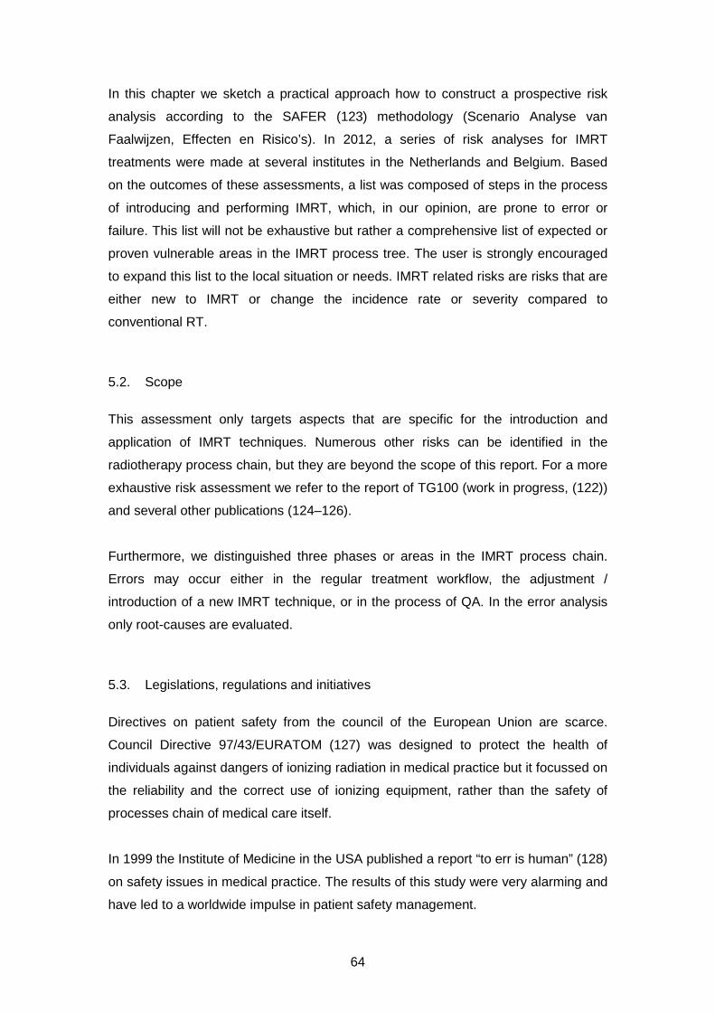
64
In this chapter we sketch a practical approach how to construct a prospective risk
analysis according to the SAFER (123) methodology (Scenario Analyse van
Faalwijzen, Effecten en Risico’s). In 2012, a series of risk analyses for IMRT
treatments were made at several institutes in the Netherlands and Belgium. Based
on the outcomes of these assessments, a list was composed of steps in the process
of introducing and performing IMRT, which, in our opinion, are prone to error or
failure. This list will not be exhaustive but rather a comprehensive list of expected or
proven vulnerable areas in the IMRT process tree. The user is strongly encouraged
to expand this list to the local situation or needs. IMRT related risks are risks that are
either new to IMRT or change the incidence rate or severity compared to
conventional RT.
5.2. Scope
This assessment only targets aspects that are specific for the introduction and
application of IMRT techniques. Numerous other risks can be identified in the
radiotherapy process chain, but they are beyond the scope of this report. For a more
exhaustive risk assessment we refer to the report of TG100 (work in progress, (122))
and several other publications (124–126).
Furthermore, we distinguished three phases or areas in the IMRT process chain.
Errors may occur either in the regular treatment workflow, the adjustment /
introduction of a new IMRT technique, or in the process of QA. In the error analysis
only root-causes are evaluated.
5.3. Legislations, regulations and initiatives
Directives on patient safety from the council of the European Union are scarce.
Council Directive 97/43/EURATOM (127) was designed to protect the health of
individuals against dangers of ionizing radiation in medical practice but it focussed on
the reliability and the correct use of ionizing equipment, rather than the safety of
processes chain of medical care itself.
In 1999 the Institute of Medicine in the USA published a report “to err is human” (128)
on safety issues in medical practice. The results of this study were very alarming and
have led to a worldwide impulse in patient safety management.

65
One conclusion was that a reporting system and database of accidents is mandatory
to improve the safety of the patient. This database should be filled either on a
voluntary or mandatory basis. Since accidents are fairly rare in radiotherapy, building
such a database is a slow process and the benefits are minor. Upscaling from a local
hospital database to a national or worldwide database is a very efficient manner to
share data on accidents. Also, including incidents and near-hits on a voluntary basis
is a manner to increases the efficiency of a database. Several countries (France,
Denmark, the Netherlands, UK, Canada, USA and Australia) have established such a
database on several topics (129).
In the Netherlands all hospitals have committed themselves in 2008 to establish a
safety management system (VMS). This system should enable the creation of an
environment for safe reporting of near-incidents, incidents and accidents. In each
hospital, a committee analyses these reports for the purpose of prevention. Linking
these committees between hospitals will increase the number of reports and support
the appreciation of trends, of which the PRISMA-RT community is an example. A
safety management system also constitutes retro- and prospective risk analysis. The
basis of the safety management system is defined in a norm: Nederlands Technische
Afspraak (NTA) 8009:2007 (119).
Also in Belgium initiatives to set up a safety management system are highly
supported by medical professionals, but a formal basis is lacking.
Internationally, there are several large parties which continuously advocate the need
for a common database of incidents and accidents for prevention by means of risk
analysis, so legislations can be anticipated in the near future in Europe and USA. In
Europe ROSIS (130) is an organisation within ESTRO where incidents and accidents
can be reported voluntarily and counselled an in anonymous manner. The
International Atomic Energy Agency (IAEA) and, in the USA, ASTRO (131) and the
Nuclear Regulatory Commission (NRC) (132) strongly support such databases,
whereas the Joint Commission on Accreditation of Healthcare Organizations (TJC,
formerly JCAHO) strongly advocates the use of prospective analysis in medical
practice.
66
5.4. Available Methods
In this report we will focus mainly on the practical, Dutch implementation of HFMEA
(SAFER, Dutch acronym for “Scenario Analyse van Faalwijzen Effecten en Risico’s”)
methods of constructing a risk inventory. However, there are more methods that can
give a good insight in the hazardous steps of the IMRT process chain. Here we will
not explain these methods, but the referenced articles will give a good starting point
for using these tools.
- PRISMA-RT: retrospective (133,134). Prevention Recovery Information
System for Monitoring and Analysis extended for radiotherapy. Based on
incidents, causes are identified. These causes are classified using the
Eindhoven Classification. A plan for improvement can be deduced from the
Classification Action Matrix.
- SIRE: retrospective. SIRE is an acronym for Systematic Incident
Reconstruction and Evaluation. Reconstruction of a single (major) incident
and analysis of root causes. Typically performed after a severe incident or
incidents with a high repetition frequency.
- Bow-Tie. Retrospective / prospective. Identification of causes of an incident,
possible outcomes and safety barriers (135).
- Hazard and Operability (HAZOP) study and Safety Integrity Level (SIL).
HAZOP is a prospective stress test to establish a risk profile that is used to
determine which measures are to be taken to decimate high risks to
acceptable levels.
5.5. HFMEA / SAFER
(Healthcare) Failure Mode and Effects Analysis is a method for prospective risk
analysis and has been described in detail elsewhere (136). It was first developed at
the VA National Center for Patient Safety in America by DeRosier et al. In 2006, a
ZonMW project resulted in a Dutch translation of HFMEA that was adopted to the
Dutch healthcare situation (137,123,138). Not only the risk assessment itself is
described, the entire process of risk management is outlined. SAFER deviates
slightly from HFMEA on some points:
• SAFER is not just a prospective risk analysis. It is a complete paradigm to improve
safety in a healthcare environment (process → problem → solution).
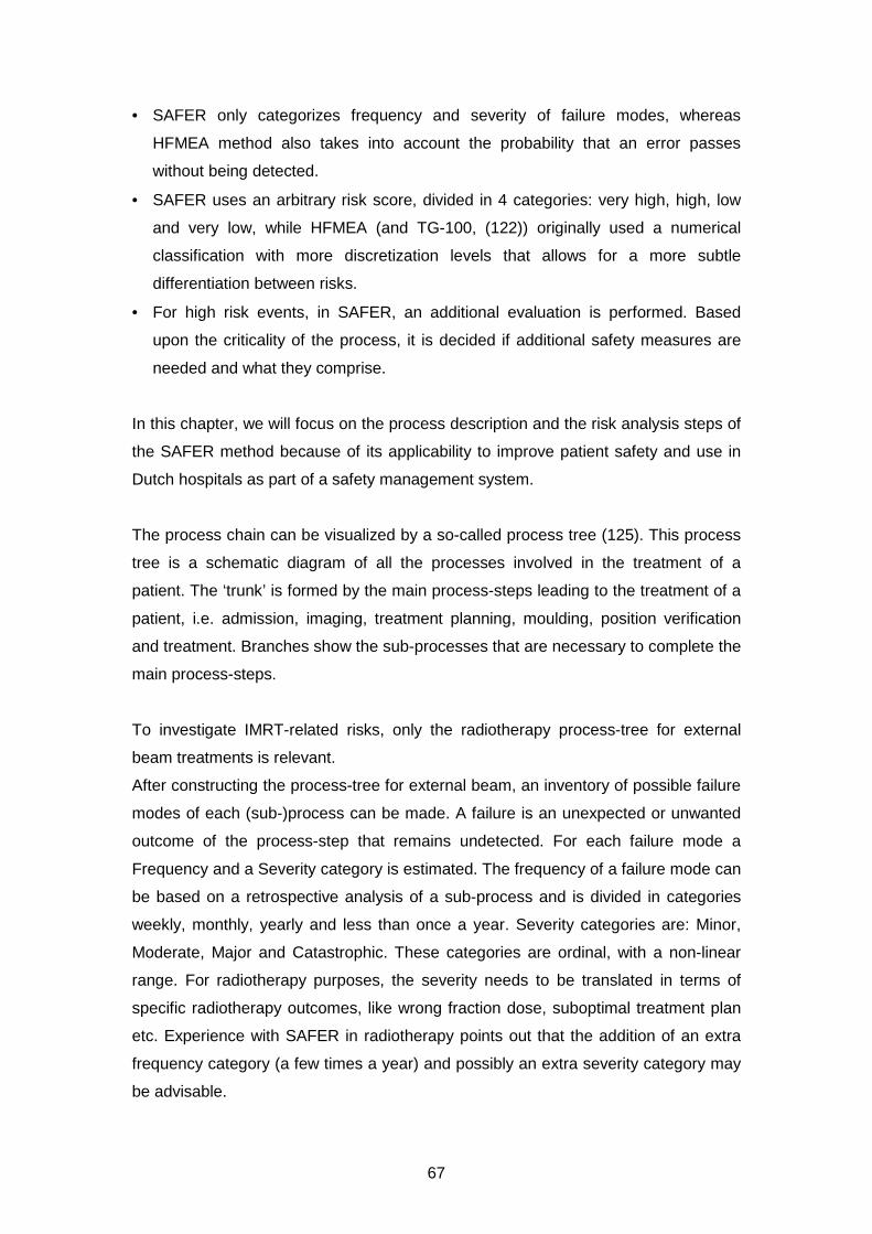
67
• SAFER only categorizes frequency and severity of failure modes, whereas
HFMEA method also takes into account the probability that an error passes
without being detected.
• SAFER uses an arbitrary risk score, divided in 4 categories: very high, high, low
and very low, while HFMEA (and TG-100, (122)) originally used a numerical
classification with more discretization levels that allows for a more subtle
differentiation between risks.
• For high risk events, in SAFER, an additional evaluation is performed. Based
upon the criticality of the process, it is decided if additional safety measures are
needed and what they comprise.
In this chapter, we will focus on the process description and the risk analysis steps of
the SAFER method because of its applicability to improve patient safety and use in
Dutch hospitals as part of a safety management system.
The process chain can be visualized by a so-called process tree (125). This process
tree is a schematic diagram of all the processes involved in the treatment of a
patient. The ‘trunk’ is formed by the main process-steps leading to the treatment of a
patient, i.e. admission, imaging, treatment planning, moulding, position verification
and treatment. Branches show the sub-processes that are necessary to complete the
main process-steps.
To investigate IMRT-related risks, only the radiotherapy process-tree for external
beam treatments is relevant.
After constructing the process-tree for external beam, an inventory of possible failure
modes of each (sub-)process can be made. A failure is an unexpected or unwanted
outcome of the process-step that remains undetected. For each failure mode a
Frequency and a Severity category is estimated. The frequency of a failure mode can
be based on a retrospective analysis of a sub-process and is divided in categories
weekly, monthly, yearly and less than once a year. Severity categories are: Minor,
Moderate, Major and Catastrophic. These categories are ordinal, with a non-linear
range. For radiotherapy purposes, the severity needs to be translated in terms of
specific radiotherapy outcomes, like wrong fraction dose, suboptimal treatment plan
etc. Experience with SAFER in radiotherapy points out that the addition of an extra
frequency category (a few times a year) and possibly an extra severity category may
be advisable.
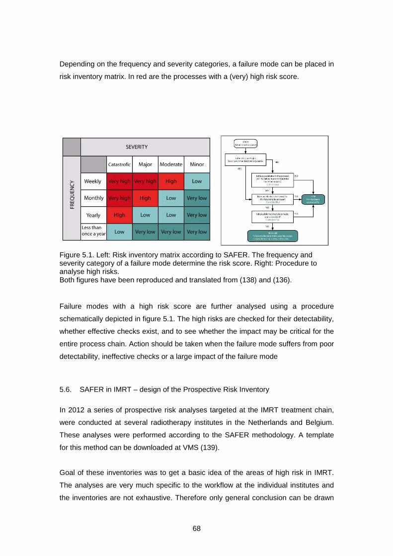
68
Depending on the frequency and severity categories, a failure mode can be placed in
risk inventory matrix. In red are the processes with a (very) high risk score.
Figure 5.1. Left: Risk inventory matrix according to SAFER. The frequency and severity category of a failure mode determine the risk score. Right: Procedure to analyse high risks. Both figures have been reproduced and translated from (138) and (136).
Failure modes with a high risk score are further analysed using a procedure
schematically depicted in figure 5.1. The high risks are checked for their detectability,
whether effective checks exist, and to see whether the impact may be critical for the
entire process chain. Action should be taken when the failure mode suffers from poor
detectability, ineffective checks or a large impact of the failure mode
5.6. SAFER in IMRT – design of the Prospective Risk Inventory
In 2012 a series of prospective risk analyses targeted at the IMRT treatment chain,
were conducted at several radiotherapy institutes in the Netherlands and Belgium.
These analyses were performed according to the SAFER methodology. A template
for this method can be downloaded at VMS (139).
Goal of these inventories was to get a basic idea of the areas of high risk in IMRT.
The analyses are very much specific to the workflow at the individual institutes and
the inventories are not exhaustive. Therefore only general conclusion can be drawn
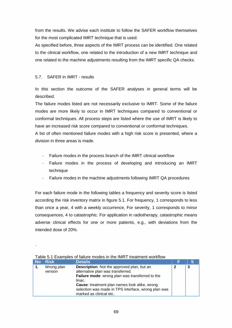
69
from the results. We advise each institute to follow the SAFER workflow themselves
for the most complicated IMRT technique that is used.
As specified before, three aspects of the IMRT process can be identified. One related
to the clinical workflow, one related to the introduction of a new IMRT technique and
one related to the machine adjustments resulting from the IMRT specific QA checks.
5.7. SAFER in IMRT - results
In this section the outcome of the SAFER analyses in general terms will be
described.
The failure modes listed are not necessarily exclusive to IMRT. Some of the failure
modes are more likely to occur in IMRT techniques compared to conventional or
conformal techniques. All process steps are listed where the use of IMRT is likely to
have an increased risk score compared to conventional or conformal techniques.
A list of often mentioned failure modes with a high risk score is presented, where a
division in three areas is made.
- Failure modes in the process branch of the IMRT clinical workflow
- Failure modes in the process of developing and introducing an IMRT
technique
- Failure modes in the machine adjustments following IMRT QA procedures
For each failure mode in the following tables a frequency and severity score is listed
according the risk inventory matrix in figure 5.1. For frequency, 1 corresponds to less
than once a year, 4 with a weekly occurrence, For severity, 1 corresponds to minor
consequences, 4 to catastrophic. For application in radiotherapy, catastrophic means
adverse clinical effects for one or more patients, e.g., with deviations from the
intended dose of 20%.
.
Table 5.1 Examples of failure modes in the IMRT treatment workflow No Risk Details F S 1. Wrong plan
version Description: Not the approved plan, but an alternative plan was transferred. Failure mode: wrong plan was transferred to the linac. Cause: treatment plan names look alike, wrong selection was made in TPS interface, wrong plan was marked as clinical etc.
2 3
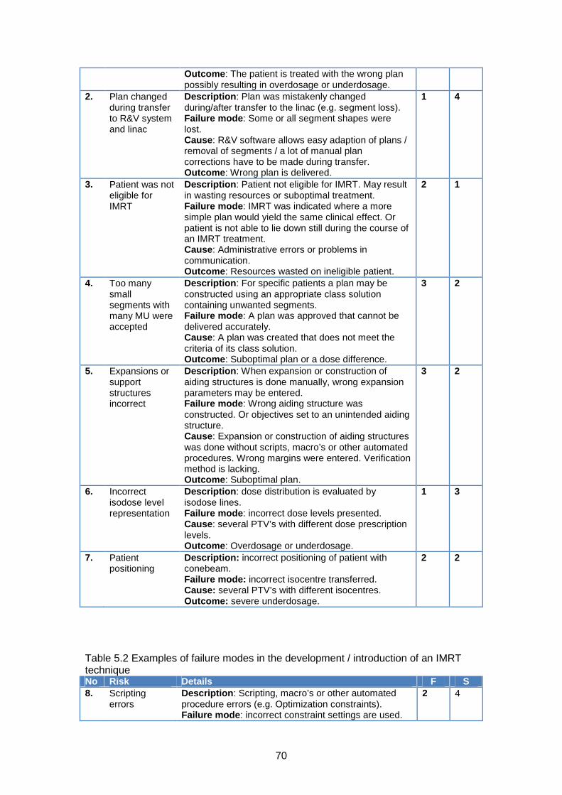
70
Outcome: The patient is treated with the wrong plan possibly resulting in overdosage or underdosage.
2. Plan changed during transfer to R&V system and linac
Description: Plan was mistakenly changed during/after transfer to the linac (e.g. segment loss). Failure mode: Some or all segment shapes were lost. Cause: R&V software allows easy adaption of plans / removal of segments / a lot of manual plan corrections have to be made during transfer. Outcome: Wrong plan is delivered.
1 4
3. Patient was not eligible for IMRT
Description: Patient not eligible for IMRT. May result in wasting resources or suboptimal treatment. Failure mode: IMRT was indicated where a more simple plan would yield the same clinical effect. Or patient is not able to lie down still during the course of an IMRT treatment. Cause: Administrative errors or problems in communication. Outcome: Resources wasted on ineligible patient.
2 1
4. Too many small segments with many MU were accepted
Description: For specific patients a plan may be constructed using an appropriate class solution containing unwanted segments. Failure mode: A plan was approved that cannot be delivered accurately. Cause: A plan was created that does not meet the criteria of its class solution. Outcome: Suboptimal plan or a dose difference.
3 2
5. Expansions or support structures incorrect
Description: When expansion or construction of aiding structures is done manually, wrong expansion parameters may be entered. Failure mode: Wrong aiding structure was constructed. Or objectives set to an unintended aiding structure. Cause: Expansion or construction of aiding structures was done without scripts, macro’s or other automated procedures. Wrong margins were entered. Verification method is lacking. Outcome: Suboptimal plan.
3 2
6. Incorrect isodose level representation
Description: dose distribution is evaluated by isodose lines. Failure mode: incorrect dose levels presented. Cause: several PTV’s with different dose prescription levels. Outcome: Overdosage or underdosage.
1 3
7. Patient positioning
Description: incorrect positioning of patient with conebeam. Failure mode: incorrect isocentre transferred. Cause: several PTV’s with different isocentres. Outcome: severe underdosage.
2 2
Table 5.2 Examples of failure modes in the development / introduction of an IMRT technique No Risk Details F S 8. Scripting
errors Description: Scripting, macro’s or other automated procedure errors (e.g. Optimization constraints). Failure mode: incorrect constraint settings are used.
2 4

71
Cause: scripting errors cause systematically wrong settings or operations. Wrong expansions � wrong margins. Outcome: a suboptimal plan is delivered.
9. Class solutions not valid anymore
Description: protocols or planning parameters, i.e., dose levels, are changed without checking the validity of the class solution. Failure mode: a suboptimal plan is delivered. Cause: solution was not validated for revised dose levels. Outcome: suboptimal plan is delivered.
2 3
10. No suitable verification technique used
Description: Limitation of measurement method is not fully recognized. Failure mode: Measurements are not reliable. Ionization chambers can be too large to determine penumbras accurately, a matrix of ionization chambers is too coarsely spaced to notice abutting field effects, absolute film dosimetry may not be accurate. Cause: lack of education. Outcome: Overdosage/underdosage of 3% to 10% are possible.
1 3
11. Wrong modelling of MLC / leaf tip in TPS
Description: deviation between calculations and measurements in low dose regions. Failure mode: Transmissions not accurately modelled. Cause: insufficient attention to modelling of low dose regions during acceptance and commissioning of TPS Outcome: Penumbras, tongue and groove effects, shallow gradients are not optimally modelled in the TPS. Sub-optimal treatment plan.
1 4
12. Incorrect output factors
Description: Incorrect output factors in TPS. Failure mode: output factors were not accurately determined. Cause: Wrong measurement techniques were used, especially for small fields. Outcome: Dose difference.
1 4
13. Incorrect Use of biological objectives
Description: optimisation is performed with incorrect objectives. Failure mode: Incorrect objectives or incorrect parameters of the objective are used. Cause: Type error, or it is not clear what the best objective or correct parameter is. Outcome: Wrong or suboptimal plan delivered.
2 2
14. Incorrect analysis
Description: Gamma analysis is performed with a set of parameters: distance to agreement (DTA). Failure mode: incorrect parameter set. Example: DTA = 5%/1mm instead of 3%/2mm. Cause: typing error, wrong protocol. Outcome: false positive or false negative indication. Deviations between planning and measurements go unnoticed.
2 2
Table 5.3 Examples of failure modes in machine adjustments after IMRT specific QA. No Risk Details F S 15. Wrong leaf
bank calibration after strip test
Description: measurements demonstrate the need for new leaf calibration Failure mode: leaf calibration performed on the incorrect leafbank Cause: error due to reduced attention in combination
2 3

72
of a lack of verification measurements Outcome: significant local dose deviations
16. Too much play on machine isocentre
Description: For old machines the mechanical properties may change over time and become inadequate to continue delivering IMRT-treatments. Failure mode: Delivery of IMRT-segments is imprecise. Abutment problems. Cause: Too much play in the mechanical isocentre. Outcome: Suboptimal plan delivery.
1 4
17.
Incorrect analysis
Description: Gamma analysis is performed with a set of parameters: distance to agreement (DTA) Failure mode: incorrect parameter set. Example: DTA = 5%/1mm instead of 3%/2mm Cause: typing error, wrong protocol Outcome: false positive or false negative indication. Deviations between planning and measurements go unnoticed.
2 2
Failure modes due to treatment with wrong machine parameters may be caused by
errors in adjusting these parameters after QA tests or by gradual drift due to
insufficient QA. Both result in treating with wrong machine parameters. Again, only
failure modes are considered that are more pronounced in the application of IMRT.
5.8. Risk profile in radiotherapy
A lot of work has been done to categorize incidents and accidents in radiotherapy in
order to obtain risk profiles. In this paragraph the results of three major reports are
shortly discussed.
In the literature several databases are used to determine the causes of the specific
events. Both the databases of Nuclear Regulatory Commission (NRC) (140) and The
Joint Commission (141) (TJC, formerly the Joint Commission on Accreditation of
Hospitals (JCAHO)) show a large contribution of human errors (~20%) as cause of
incidents. It is interesting from a perspective of prevention to determine co-factors
that enable these human errors to occur.
Based on incidents with radioactive material in Nuclear Medical Events Database
(NMED) of the NRC and other databases several co-factors were determined (140).
Many of these factors are applicable to external beam radiotherapy in general, and to
some extend to IMRT specifically. One co-factor of human errors is the black box
aspect of automation. As with sophisticated automation, the role of the human in the
process shifts from an operator towards a checker. Consequently there is verification
whether the process has been completed, but it is not directly clear how it was
completed and/or if there were any disturbances during the process. Some process

73
steps in the IMRT chain are highly automated and can result in reduced control and
diminished understanding of the underlying process such as for instance automatic
plan set up, automatic organ contouring and optimisation routines.
Furthermore, this black box aspect of IMRT inhibits plausibility checks that are used
for conventional techniques like similarities between field shape (Beam’s eye view)
and shape of the target volumes and the relation between number of monitor units
and the total dose prescribed. These checks cannot be used for IMRT because many
field or segment shapes are typically non-intuitive and/or the number of MU is only
weakly correlated with total dose.
In a report of the UK Chief Medical Officer 2006 from a radiotherapy incident
database (142) three origins of failure were frequently reported: 1) Misinformation or
error in data transfer, 2) Lack of training in new techniques and 3) Checks for
process failures do not work.
The first issue holds for radiotherapy in general. The same conclusion was drawn
from a literature study performed by the WHO (143). Data transfer should be done
digitally, and if manual data entry is not mandatory it should be discouraged. On the
other hand, a critical attitude towards computer programs is warranted. Issue 2) is for
IMRT very important. IMRT planning requires training and understanding of technical
features. Procedures during treatment planning are highly automated and require
knowledge of how this complex system works. Insight in the limitations of the
planning system is required. Plans that contain highly irregular segments or result in
large dose gradients in the proximity of critical structures should be presented to a
physicist. Training is also the key to the human error reduction (144) as found in the
NRC report. Issue 3): Incorporated checks are important means to make the process
safer, but be critical whether these checks are independent from each other and
have a low pass rate for the tasks they were designed for. Pre-treatment patient
specific QA can reveal errors but not all types of errors (116).
The International Commission on Radiological Protection (ICRP) report is based on
literature about how to prevent accidental exposures from new external beam
irradiation therapy technologies (145). They concluded that, in general, radiation
accidents are most effectively prevented in areas with a well implemented safety
culture. A patient safety programme should be integrated in the working process.
Ingredients are: clear responsibilities and a blame-free reporting system. Trends in
incidents can be appreciated and safety improvements are not only initiated by

74
incidents. Also the report stresses the importance of an adequate education that
matches the tasks performed.
Regarding new irradiation techniques the report notes the omnipresence of
computers. There lies a risk: people tend to rely heavily on the output of computer
programs. Especially if there are no simple means to verify these results or no insight
is provided how the program works. This is a hazardous situation that can only be
solved by education, training and a critical attitude towards computers, computer
software and their results.
5.9. Recommendations
Based on the failure modes listed in the previous section, a few general
recommendations can be made to address some of the most vulnerable steps in
IMRT. It must be stressed that the list is not exhaustive and may not completely
reflect the workflow in all departments.
It is therefore suggested that each department constructs its own process tree. With
this tree the interaction between process steps becomes apparent and it reveals how
errors may migrate from one process to the other. Furthermore, it is advised to set up
a prospective risk analysis for at least the most complex external beam process. A
prospective risk analysis, specific for each department, should be conducted to
reveal additional weaknesses in workflow. Retrospective analysis of incidents can be
helpful to address certain classes of risks and to assess the incidence rate.
In the next table the recommendations are summarized. In the second column the
number of the specific risk / failure mode is listed. These refer to the numbers in
tables of section 5.7.
Table 5.4 Recommendations .Recommendation Addresses Risk # Have the MD sign the plan digitally in the TPS, and provide a way to lock the plan status. Make sure that only approved plans can be transferred.
1
Check plan integrity before delivery to guarantee delivery of the intended plan. 2. Thoroughly check scripts, macro’s or other automated procedures before clinical introduction. Have your script reviewed. Use a standard group of test patients to check the validity.
8, 6, 5.
After each change IMRT prescription or optimization settings, check the validity of the class solution. Is it still optimal?
4, 9.
For each patient plan check whether the constraints for the patient plan meet the requirements for the class solution.
4

75
Independent dose check by measurement or calculation. 1, 2 Have an independent plan check after the planning process is complete. Check for irregular, segments. MU per segment, basic optimization and calculation parameters. Further, recheck margins / expansions used.
1, 2, 4, 5
If possible, use scripts or macros to automate steps in the planning process that are error prone. If the TPS does not facilitate scripts or macro’s, adjust procedures in a manner that specific errors cannot occur
5
Secure the procedure of introducing new IMRT techniques or adapt existing techniques.
3, 9, 10, 12
Implement a test to evaluate the entire radiotherapy process (End to End test) using a single phantom, Different aspects can be evaluated: logistics, dose accuracy, patient positioning issues, transit times , etc.
8 - 17
Have a proper QA program for the QA equipment. 10, 12 Proper education or training of staff. 9 - 13 A general and obvious point can be made regarding the adjustment of machine
parameters. It is clear that each adjustment should be followed by a final
independent check of the corrected parameters. It may be a good idea to have a
time-out procedure when large adjustments need to be made following from QA
measurements. Try more than one measurement method and ask someone else to
reproduce the measurement independently.
IMRT treatment planning and delivery are complex processes that can be susceptible
to errors when control fails. Checks, double checks and verification are very
important and simple methods to catch errors in this condition. Another approach to
reduce errors or incidents is by prevention, i.e. to prevent errors or incidents to occur.
In order to prevent incidents a safety culture should be established that is supported
by the entire staff. A fundamental aspect in error prevention is education. It is of
crucial importance that the level of education matches with the tasks to be
performed. The relationship between human errors and adequate education has
been demonstrated in several articles (146,147). In our list of examples errors related
to education and training of staff can result in systematic errors and affect many
treatment plans. Given this nature of these errors proper education is mandatory. In a
paper of Moran et al. (148) and others (149) the specific needs for education and
responsibilities in IMRT are clearly summarized. They also stress the importance of
intense communication between the professionals, as it was assessed that the IMRT
process consisted of many process steps, including 15 hand-offs. These hand-off
moments are characterized by a shift in the responsibility, of the one professional to
the other, for a process step in the treatment chain. In these hand-offs, the presence
and quality of the required information is of utter importance for the professional to
perform its task in a correct and safe manner (150).

76
Acknowledgements
The subcommittee would like to thank the NCS for the opportunity to write this report.
Additionally, we would like to thank the external reviewers Frits Wittkämper and Theo
van Soest for their comments and in particular Danny Schuuring for his critical review
and extensive comments.

77
References
1. NCS 15. Quality assurance of 3-D treatment planning systems for external photon and electron beams. NCS. 2006;
2. NCS 18. Code of Practice for the Absorbed Dose Determination in High Energy Photon and Electron Beams. NCS. 2008;
3. NCS 8. Kwaliteitscontrole van Medische Lineaire Versnellers, methoden voor kwaliteitscontrole, wenselijke toleranties en frequenties. NCS. 1995;
4. Mijnheer, Olszewska, Fiorino, Hartmann, Knöös, Rosenwald, Welleweerd. Quality Assurance of Treatment Planning Systems – Practical Examples for non-IMRT Photon Beams. ESTRO; 2004.
5. Ibbott, Followill, Molineu, Lowenstein, Alvarez, Roll. Challenges in credentialing institutions and participants in advanced technology multi-institutional clinical trials. International journal of radiation oncology, biology, physics. 2008;S71–5.
6. Molineu, Hernandez, Nguyen, Ibbott, Followill. Credentialing results from IMRT irradiations of an anthropomorphic head and neck phantom. Medical physics. 2013;022101.
7. Fairchild, Bar-Deroma, Collette, Haustermans, Hurkmans, Lacombe, Maingon, Poortmans, Tomsej, Weber, Gregoire. Development of clinical trial protocols involving advanced radiation therapy techniques: the European Organisation for Research and Treatment of Cancer Radiation Oncology Group approach. European journal of cancer. 2012;1048–54.
8. Tomsej. A new collaborative ESTRO-OECI Task Group on implementation of external postal dosimetry audit for new technologies in radiotherapy clinical trials: the Helical Tomotherapy Working Group. Radiotherapy and Oncology. 2007;S75–S86.
9. Tomsej, Marchesi, Aletti, GORTEC Physicists. Validation of IMRT treatments in head and neck cancer through a European multicentric dosimetry study. Radiotherapy and oncology. 2005;S40.
10. Gillis, De Wagter, Bohsung, Perrin, Williams, Mijnheer. An inter-centre quality assurance network for IMRT verification: results of the ESTRO QUASIMODO project. Radiotherapy and oncology. 2005;340–53.
11. Molineu, Followill, Balter, Hanson, Gillin, Huq, Eisbruch, Ibbott. Design and implementation of an anthropomorphic quality assurance phantom for intensity-modulated radiation therapy for the Radiation Therapy Oncology Group. International journal of radiation oncology, biology, physics. 2005;577–83.
12. Palta. Acceptance Testing, Commissioning & Quality Assurance of Medical Linear Accelerators [Internet]. AAPM, annual meeting. 2002. Available from: www.aapm.org/meetings/02AM/pdf/8351-37037.pdf
78
13. Klein, Hanley, Bayouth, Yin, Simon, Dresser, Serago, Aguirre, Ma, Arjomandy, Liu, Sandin, Holmes. Task Group 142 report: quality assurance of medical accelerators. Medical physics. 2009;4197–212.
14. Mu, Ludlum, Xia. Impact of MLC leaf position errors on simple and complex IMRT plans for head and neck cancer. Physics in medicine and biology. 2008;77–88.
15. Oliver, Gagne, Bush, Zavgorodni, Ansbacher, Beckham. Clinical significance of multi-leaf collimator positional errors for volumetric modulated arc therapy. Radiotherapy and oncology. 2010;554–60.
16. Rangel, Dunscombe. Tolerances on MLC leaf position accuracy for IMRT delivery with a dynamic MLC. Medical physics. 2009;3304–9.
17. Besluit stralingsbescherming [Internet]. 2001. p. Staatsblad 2001–3972001. Available from: http://wetten.overheid.nl/BWBR0012702/
18. IEC. Medical Electrical Equipment – Medical Electron Accelerators – Guidelines For Functional Performance Characteristics. Publication 977. 2007.
19. IPEM. Acceptance Testing and Commissioning of Linear Accelerators. Report 94. 2006.
20. Bohsung, Gillis, Arrans, Bakai, De Wagter, Knöös, Mijnheer, Paiusco, Perrin, Welleweerd, Williams. IMRT treatment planning:- a comparative inter-system and inter-centre planning exercise of the ESTRO QUASIMODO group. Radiotherapy and oncology. 2005;354–61.
21. Alfonso, Andreo, Capote, Huq, Kilby, Kjäll, Mackie, Palmans, Rosser, Seuntjens, Ullrich, Vatnitsky. A new formalism for reference dosimetry of small and nonstandard fields. Medical physics. 2008;5179–86.
22. Crop, Reynaert, Pittomvils, Paelinck, De Gersem, De Wagter, Vakaet, De Neve, Thierens. Monte Carlo modeling of the ModuLeaf miniature MLC for small field dosimetry and quality assurance of the clinical treatment planning system. Physics in medicine and biology. 2007;3275–90.
23. Das, Ding, Ahnesjö. Small fields: nonequilibrium radiation dosimetry. Medical physics. 2008;206–15.
24. IPEM. Small Field MV Photon Dosimetry. Report 103. 2010.
25. Martens, De Wagter, De Neve. The value of the LA48 linear ion chamber array for characterization of intensity-modulated beams. Physics in medicine and biology. 2001;1131–48.
26. Pittomvils, Coghe, De Gersem, Crop, Van Duyse, Jacobs, De Wagter, De Neve. Measurement techniques, modeling strategies and pitfalls to avoid when implementing a mini MLC in a non dedicated planning system. Strahlentherapie und Onkologie. 2007;637–44.

79
27. Podgorsak. Physics for radiosurgery with linear accelerators. Neurosurgery clinics of North America. 1992;9–34.
28. Lutz, Winston, Maleki. A system for stereotactic radiosurgery with a linear accelerator. International journal of radiation oncology, biology, physics. 1988;373–81.
29. Treuer, Hoevels, Luyken, Gierich, Kocher, Müller, Sturm. On isocentre adjustment and quality control in linear accelerator based radiosurgery with circular collimators and room lasers. Physics in medicine and biology. 2000;2331–42.
30. Karger, Hartmann, Heeg, Jäkel. A method for determining the alignment accuracy of the treatment table axis at an isocentric irradiation facility. Physics in medicine and biology. 2001;N19–26.
31. Ezzell, Galvin, Low, Palta, Rosen, Sharpe, Xia, Xiao, Xing, Yu. Guidance document on delivery, treatment planning, and clinical implementation of IMRT: report of the IMRT Subcommittee of the AAPM Radiation Therapy Committee. Medical physics. 2003;2089–115.
32. Hartford, Palisca, Eichler, Beyer, Devineni, Ibbott, Kavanagh, Kent, Rosenthal, Schultz, Tripuraneni, Gaspar. American Society for Therapeutic Radiology and Oncology (ASTRO) and American College of Radiology (ACR) Practice Guidelines for Intensity-Modulated Radiation Therapy (IMRT). International journal of radiation oncology, biology, physics. 2009;9–14.
33. Low. Quality assurance of intensity-modulated radiotherapy. Seminars in radiation oncology. 2002;219–28.
34. Losasso. IMRT delivery performance with a varian multileaf collimator. International journal of radiation oncology, biology, physics. 2008;S85–8.
35. Liu, Simon, Fox, Li, Palta. Multileaf collimator characteristics and reliability requirements for IMRT Elekta system. International journal of radiation oncology, biology, physics. 2008;S89–92.
36. Bayouth. Siemens multileaf collimator characterization and quality assurance approaches for intensity-modulated radiotherapy. International journal of radiation oncology, biology, physics. 2008;S93–7.
37. Das, Cheng, Watts, Ahnesjö, Gibbons, Li, Lowenstein, Mitra, Simon, Zhu. Accelerator beam data commissioning equipment and procedures: report of the TG-106 of the Therapy Physics Committee of the AAPM. Medical physics. 2008;4186–215.
38. Chui, LoSasso, Spirou. Dose calculation for photon beams with intensity modulation generated by dynamic jaw or multileaf collimations. Medical physics. 1994;1237–44.
39. LoSasso, Chui, Ling. Comprehensive quality assurance for the delivery of intensity modulated radiotherapy with a multileaf collimator used in the dynamic mode. Medical physics. 2001;2209–19.
80
40. LoSasso. Intensity-ModuAAPM Medical Physics Monograph No. 29. Intensity-Modulated Radiation Therapy. The State of the ART. p. 561–91.
41. Chang, Obcemea, Sillanpaa, Mechalakos, Burman. Use of EPID for leaf position accuracy QA of dynamic multi-leaf collimator (DMLC) treatment. Medical physics. 2004;2091–6.
42. Boyer, Biggs, Galvin, Klein, LoSasso, Low, Mah, Yu. Basic Applications of Multileaf Collimators. 2001.
43. Low, Sohn, Klein, Markman, Mutic, Dempsey. Characterization of a commercial multileaf collimator used for intensity modulated radiation therapy. Medical physics. 2001;752–6.
44. Sastre-Padro, Van der Heide, Welleweerd. An accurate calibration method of the multileaf collimator valid for conformal and intensity modulated radiation treatments. Physics in medicine and biology. 2004;2631–43.
45. Spezi, Angelini, Romani, Ferri. Characterization of a 2D ion chamber array for the verification of radiotherapy treatments. Physics in medicine and biology. 2005;3361–73.
46. Yang, Xing, Li, Palta, Chen, Luxton, Boyer. Independent dosimetric calculation with inclusion of head scatter and MLC transmission for IMRT. Medical physics. 2003;2937–47.
47. LoSasso, Chui, Ling. Physical and dosimetric aspects of a multileaf collimation system used in the dynamic mode for implementing intensity modulated radiotherapy. Medical physics. 1998;1919–27.
48. Vial, Oliver, Greer, Baldock. An experimental investigation into the radiation field offset of a dynamic multileaf collimator. Physics in medicine and biology. 2006;5517–38.
49. Wasbø, Valen. Dosimetric discrepancies caused by differing MLC parameters for dynamic IMRT. Physics in medicine and biology. 2008;405–15.
50. Vieira, Dirkx, Pasma, Heijmen. Fast and accurate leaf verification for dynamic multileaf collimation using an electronic portal imaging device. Medical physics. 2002;2034–40.
51. Huq, Das, Steinberg, Galvin. A dosimetric comparison of various multileaf collimators. Physics in medicine and biology. 2002;N159–70.
52. Ravikumar, Al Asmary, Alla A Sultan, Al Ghamdi. Dose delivery accuracy of therapeutic photon and electron beams at low monitor unit settings. Strahlentherapie und Onkologie. 2005;796–9.
53. Mohr, Brieger, Stahl, Witucki. Linearity of the dose monitor system at low monitor units. Strahlentherapie und Onkologie. 2007;327–31.

81
54. Kang, Cheong, Hwang, Cho, Kim, Kim, Oh, Bae, Suh. Dosimetric characteristics of linear accelerator photon beams with small monitor unit settings. Medical physics. 2008;5172–8.
55. IAEA. IAEA Safety Reports Series No. 47 Radiation Protection in the Design of Radiotherapy Facilities. 2006.
56. IPEM. Design of Radiotherapy Treatment Room Facilities. Report 75. 1997.
57. NCRP. Structural Shielding Design and Evaluation for Megavoltage X- and Gamma-Ray Radiotherapy Facilities [Internet]. NCRP Report 151. [cited 2013 Jan 27]. Available from: http://www.scribd.com/doc/47437337/NCRP-Report-151
58. Stathakis, Price, Ma. Dosimetry validation of treatment room shielding design. Medical physics. 2005;448–54.
59. Williams. IMRT: delivery techniques and quality assurance. The British journal of radiology. 2003;766–76.
60. Zhu, Ahnesjö, Lam, Li, Ma, Palta, Sharpe, Thomadsen, Tailor. Report of AAPM Therapy Physics Committee Task Group 74: in-air output ratio, Sc, for megavoltage photon beams. Medical physics. 2009;5261–91.
61. Ezzell, Burmeister, Dogan, LoSasso, Mechalakos, Mihailidis, Molineu, Palta, Ramsey, Salter, Shi, Xia, Yue, Xiao. IMRT commissioning: multiple institution planning and dosimetry comparisons, a report from AAPM Task Group 119. Medical physics. 2009;5359–73.
62. Jordan, Williams. The design and performance characteristics of a multileaf collimator. Physics in medicine and biology. 1994;231–51.
63. Bedford, Lee, Wai, South, Warrington. Evaluation of the Delta4 phantom for IMRT and VMAT verification. Physics in medicine and biology. 2009;N167–76.
64. Boyer, Li. Geometric analysis of light-field position of a multileaf collimator with curved ends. Medical physics. 1997;757–62.
65. Williams, Metcalfe. Verification of a rounded leaf-end MLC model used in a radiotherapy treatment planning system. Physics in medicine and biology. 2006;N65–78.
66. Chauvet, Petitfils, Lehobey, Kristner, Brunet, Lembrez, Gaboriaud, Mazal, Zefkili, Rosenwald. The sliding slit test for dynamic IMRT: a useful tool for adjustment of MLC related parameters. Physics in medicine and biology. 2005;563–80.
67. Sykes, Williams. An experimental investigation of the tongue and groove effect for the Philips multileaf collimator. Physics in medicine and biology. 1998;3157–65.
68. Patel, Glendinning, Kirby. Dosimetric characteristics of the Elekta Beam Modulator. Physics in medicine and biology. 2005;5479–92.

82
69. Brualla-González, Gómez, Vicedo, González-Castaño, Gago-Arias, Pazos, Zapata, Roselló, Pardo-Montero. A two-dimensional liquid-filled ionization chamber array prototype for small-field verification: characterization and first clinical tests. Physics in medicine and biology. 2012;5221–34.
70. Price, Chibani, Ma. Shielding evaluation for IMRT implementation in an existing accelerator vault. Journal of applied clinical medical physics / American College of Medical Physics. 2003;231–8.
71. Venselaar, Welleweerd, Mijnheer. Tolerances for the accuracy of photon beam dose calculations of treatment planning systems. Radiotherapy and oncology. 2001;191–201.
72. Schwarz, Bos, Mijnheer, Lebesque, Damen. Importance of accurate dose calculations outside segment edges in intensity modulated radiotherapy treatment planning. Radiotherapy and oncology. 2003;305–14.
73. Abate, Pressello, Benassi, Strigari. Comparison of IMRT planning with two-step and one-step optimization: a strategy for improving therapeutic gain and reducing the integral dose. Physics in medicine and biology. 2009;7183–98.
74. Broderick, Leech, Coffey. Direct aperture optimization as a means of reducing the complexity of Intensity Modulated Radiation Therapy plans. Radiation oncology (London, England). 2009;8.
75. Treutwein, Hipp, Kölbl, Bogner. IMRT of prostate cancer: a comparison of fluence optimization with sequential segmentation and direct step-and-shoot optimization. Strahlentherapie und Onkologie. 2009;379–83.
76. Phillips, Cho, Parsai, Douglas. Use of intensity modulation for missing tissue compensation of pediatric spinal fields. Journal of applied clinical medical physics / American College of Medical Physics. 2003;274–81.
77. Worthy, Wu. Parameter optimization in HN-IMRT for Elekta linacs. Journal of applied clinical medical physics / American College of Medical Physics. 2009;2951.
78. Srivastava, De Wagter. The effects of incidence angle on film dosimetry and their consequences in IMRT dose verification. Medical physics. 2012;6129–38.
79. Yeo, Beiki-Ardakani, Cho, Heydarian, Zhang, Islam. EDR2 film dosimetry for IMRT verification using low-energy photon filters. Medical physics. 2004;1960–3.
80. Duggan, Coffey. Small photon field dosimetry for stereotactic radiosurgery. Medical dosimetry�: official journal of the American Association of Medical Dosimetrists. 1998;153–9.
81. Zhu, Bjärngard. The head-scatter factor for small field sizes. Medical physics. 1994;65–8.
82. IAEA. Specification and Acceptance Testing of Radiotherapy Treatment Planning Systems. 2007 p. IAEA TECDOC 1540.

83
83. Nyholm, Olofsson, Ahnesjö, Karlsson. Modelling lateral beam quality variations in pencil kernel based photon dose calculations. Physics in medicine and biology. 2006;4111–8.
84. Aarup, Nahum, Zacharatou, Juhler-Nøttrup, Knöös, Nyström, Specht, Wieslander, Korreman. The effect of different lung densities on the accuracy of various radiotherapy dose calculation methods: implications for tumour coverage. Radiotherapy and oncology. 2009;405–14.
85. Fogliata, Vanetti, Albers, Brink, Clivio, Knöös, Nicolini, Cozzi. On the dosimetric behaviour of photon dose calculation algorithms in the presence of simple geometric heterogeneities: comparison with Monte Carlo calculations. Physics in medicine and biology. 2007;1363–85.
86. Gershkevitsh, Schmidt, Velez, Miller, Korf, Yip, Wanwilairat, Vatnitsky. Dosimetric verification of radiotherapy treatment planning systems: results of IAEA pilot study. Radiotherapy and oncology. 2008;338–46.
87. Hasenbalg, Neuenschwander, Mini, Born. Collapsed cone convolution and analytical anisotropic algorithm dose calculations compared to VMC++ Monte Carlo simulations in clinical cases. Physics in medicine and biology. 2007;3679–91.
88. Paelinck, Reynaert, Thierens, De Neve, De Wagter. Experimental verification of lung dose with radiochromic film: comparison with Monte Carlo simulations and commercially available treatment planning systems. Physics in medicine and biology. 2005;2055–69.
89. Polednik, Abo Madyan, Schneider, Wolff, Bannach, Lambrecht, Wallin, Cwiekala, Maurer, Reif, Lohr, Wenz. Evaluation of calculation algorithms implemented in different commercial planning systems on an anthropomorphic breast phantom using film dosimetry. Strahlentherapie und Onkologie. 2007;667–72.
90. Fotina, Winkler, Künzler, Reiterer, Simmat, Georg. Advanced kernel methods vs. Monte Carlo-based dose calculation for high energy photon beams. Radiotherapy and oncology. 2009;645–53.
91. Dobler, Walter, Knopf, Fabri, Loeschel, Polednik, Schneider, Wenz, Lohr. Optimization of extracranial stereotactic radiation therapy of small lung lesions using accurate dose calculation algorithms. Radiation oncology (London, England). 2006;45.
92. Van Esch, Bohsung, Sorvari, Tenhunen, Paiusco, Iori, Engström, Nyström, Huyskens. Acceptance tests and quality control (QC) procedures for the clinical implementation of intensity modulated radiotherapy (IMRT) using inverse planning and the sliding window technique: experience from five radiotherapy departments. Radiotherapy and oncology. 2002;53–70.
93. Sherouse. In regard to Intensity-Modulated Radiotherapy Collaborative Working Group, IJROBP 2001; 51:880-914. International journal of radiation oncology, biology, physics. 2002;1088–9.

84
94. Oldham, Sakhalkar, Guo, Adamovics. An investigation of the accuracy of an IMRT dose distribution using two- and three-dimensional dosimetry techniques. Medical physics. 2008;2072–80.
95. Van Dyk, Barnett, Cygler, Shragge. Commissioning and quality assurance of treatment planning computers. International journal of radiation oncology, biology, physics. 1993;261–73.
96. Low, Harms, Mutic, Purdy. A technique for the quantitative evaluation of dose distributions. Medical physics. 1998;656–61.
97. Depuydt, Van Esch, Huyskens. A quantitative evaluation of IMRT dose distributions: refinement and clinical assessment of the gamma evaluation. Radiotherapy and oncology. 2002;309–19.
98. Anjum, Parker, Ruo, Afzal. Evaluation criteria for film based intensity modulated radiation therapy quality assurance. Physica medica. 2010;38–43.
99. Duthoy, De Gersem, Vergote, Coghe, Boterberg, De Deene, De Wagter, Van Belle, De Neve. Whole abdominopelvic radiotherapy (WAPRT) using intensity-modulated arc therapy (IMAT): first clinical experience. International journal of radiation oncology, biology, physics. 2003;1019–32.
100. Nelms, Zhen, Tomé. Per-beam, planar IMRT QA passing rates do not predict clinically relevant patient dose errors. Medical physics. 2011;1037–44.
101. Stasi, Bresciani, Miranti, Maggio, Sapino, Gabriele. Pretreatment patient-specific IMRT quality assurance: a correlation study between gamma index and patient clinical dose volume histogram. Medical physics. 2012;7626–34.
102. Stock, Kroupa, Georg. Interpretation and evaluation of the γ index and the γ index angle for the verification of IMRT hybrid plans. Physics in Medicine and Biology. 2005;399–411.
103. Paelinck, De Neve, De Wagter. Precautions and strategies in using a commercial flatbed scanner for radiochromic film dosimetry. Physics in medicine and biology. 2007;231–42.
104. Lewis, Micke, Yu, Chan. An efficient protocol for radiochromic film dosimetry combining calibration and measurement in a single scan. Medical physics. 2012;6339–50.
105. Van Elmpt, Petit, De Ruysscher, Lambin, Dekker. 3D dose delivery verification using repeated cone-beam imaging and EPID dosimetry for stereotactic body radiotherapy of non-small cell lung cancer. Radiotherapy and oncology. 2010;188–94.
106. Mans, Remeijer, Olaciregui-Ruiz, Wendling, Sonke, Mijnheer, Van Herk, Stroom. 3D Dosimetric verification of volumetric-modulated arc therapy by portal dosimetry. Radiotherapy and oncology. 2010. p. 181–7.

85
107. McDermott, Wendling, Nijkamp, Mans, Sonke, Mijnheer, Van Herk. 3D in vivo dose verification of entire hypo-fractionated IMRT treatments using an EPID and cone-beam CT. Radiotherapy and oncology. 2008;35–42.
108. Wendling, McDermott, Mans, Sonke, Van Herk, Mijnheer. A simple backprojection algorithm for 3D in vivo EPID dosimetry of IMRT treatments. Medical Physics. 2009;3310.
109. Baker, Clements, Gately, Budgell. A separated primary and scatter model for independent dose calculation of intensity modulated radiotherapy. Radiotherapy and oncology. 2006;385–90.
110. Georg, Nyholm, Olofsson, Kjaer-Kristoffersen, Schnekenburger, Winkler, Nyström, Ahnesjö, Karlsson. Clinical evaluation of monitor unit software and the application of action levels. Radiotherapy and oncology. 2007;306–15.
111. Létourneau, Publicover, Kozelka, Moseley, Jaffray. Novel dosimetric phantom for quality assurance of volumetric modulated arc therapy. Medical Physics. 2009;1813.
112. Visser, Wauben, De Groot, Godart, Langendijk, Van’t Veld, Korevaar. Efficient and reliable 3D dose quality assurance for IMRT by combining independent dose calculations with measurements. Medical physics. 2013;021710.
113. Van Elmpt, McDermott, Nijsten, Wendling, Lambin, Mijnheer. A literature review of electronic portal imaging for radiotherapy dosimetry. Radiotherapy and oncology. 2008;289–309.
114. Van Battum, Hoffmans, Piersma, Heukelom. Accurate dosimetry with GafChromicTM EBT film of a 6 MV photon beam in water: What level is achievable? Medical Physics. 2008;704.
115. Létourneau, Gulam, Yan, Oldham, Wong. Evaluation of a 2D diode array for IMRT quality assurance. Radiotherapy and oncology. 2004;199–206.
116. Mans, Wendling, McDermott, Sonke, Tielenburg, Vijlbrief, Mijnheer, Van Herk, Stroom. Catching errors with in vivo EPID dosimetry. Medical physics. 2010;2638–44.
117. Espinosa, Núñez, Muñiz, Lagares, Embid, Gómez-Ros. Postal dosimetry audit test for small photon beams. Radiotherapy and oncology. 2012;135–41.
118. Xiang, Song, Chin, Cormack, Tishler, Makrigiorgos, Court, Chin. Build-up and surface dose measurements on phantoms using micro-MOSFET in 6 and 10 MV x-ray beams and comparisons with Monte Carlo calculations. Medical Physics. 2007;1266.
119. NTA 8009, de basiseisen voor uw VMS [Internet]. [cited 2013 Jan 27]. Available from: http://www.vmszorg.nl/Veiligheidsmanagementsysteem/Over-het-Veiligheidsmanagementsysteem/Subnavigation/NTA-8009-de-basiseisen-voor-uw-VMS-
120. NVKF. QC Light [Internet]. Available from: http://www.nvkf.nl

86
121. Platform “Stralingsbescherming in het Ziekenhuis”. Risico Inventarisatie en Analyse Stralingshygiene voor Nucleaire Geneeskunde, Radiologie en Radiotherapie [Internet]. 2012. Available from: http://www.stralingsdosimetrie.nl/stralingsbescherming-in-het-ziekenhuis/rias.php
122. AAPM TG-100. Method for Evaluating QA Needs in Radiation Therapy [Internet]. [cited 2013 Apr 3]. Available from: http://www.aapm.org/org/structure/?committee_code=TG100
123. UMC Utrecht, TU Eindhoven, MAASTRO Clinic. SAFER [Internet]. 2006 [cited 2013 Jan 27]. Available from: http://www.veiligezorgiederszorg.nl/speerpunt-vms/safer-boekje.pdf
124. Huq. New Paradigm for Quality Management in Radiation Therapy Based on Risk Analysis [Internet]. Quality and Safety in Radiotherapy. Available from: http://www.aapm.org/meetings/2011SS/documents/HuqNewParadigms.pdf
125. Thomadsen, Lin, Laemmrich, Waller, Cheng, Caldwell, Rankin, Stitt. Analysis of treatment delivery errors in brachytherapy using formal risk analysis techniques. International journal of radiation oncology, biology, physics. 2003;1492–508.
126. Williamson. Beyond FMEA: Future and Summary Outline [Internet]. AAPM. 2008 [cited 2013 Jan 27]. Available from: www.aapm.org/meetings/amos2/pdf/35-9924-97310-664.pdf
127. Official Journal of the European Community. Counsel Directive 97/43/EURATOM [Internet]. 1997. Available from: http://eur-lex.europa.eu/LexUriServ/LexUriServ.do?uri=OJ:L:1997:180:0022:0027:EN:PDF
128. Institute of Medicine. To Err Is Human: Building a Safer Health System [Internet]. 2000 [cited 2013 Jan 27]. Available from: http://www.nap.edu/openbook.php?isbn=0309068371&page=1
129. Raad voor Gezondheidsonderzoek, Advies Onderzoek Patientveiligheid. Publicatie 48 [Internet]. 2005 [cited 2013 Jan 27]. Available from: http://www.gezondheidsraad.nl/sites/default/files/Advies 48_patientveiligheid.pdf
130. ESTRO. ROSIS [Internet]. [cited 2013 Jan 27]. Available from: http://www.estro.org/projects/Pages/ROSIS.aspx
131. ASTRO. Patient Safety [Internet]. [cited 2013 Jan 27]. Available from: https://www.astro.org/Clinical-Practice/Patient-Safety/Index.aspx
132. US NRC. Briefing on Review of Patient Release Issues 10 CFR 35.75 [Internet]. 2010. [cited 2013 Jan 27]. Available from: http://www.nrc.gov/reading-rm/doc-collections/commission/slides/2010/20101020/langhorst-20101020.pdf

87
133. Schaaf TW van der. PRISMA incidenten analyse. Een instrument voor risicobeheersing in de zorgsector. Kwaliteit in Beeld. 1997;2–4.
134. PRISMA-RT [Internet]. [cited 2013 Jan 27]. Available from: http://www.prisma-rt.nl/
135. ZonMw. Risico-analyse volgens “Bow-Tie methode” voor verbetering van medicatieveiligheid [Internet]. [cited 2013 Jan 27]. Available from: http://www.zonmw.nl/nl/projecten/project-detail/risico-analyse-volgens-bow-tie-methode-voor-verbetering-van-medicatieveiligheid/
136. DeRosier, Stalhandske, Bagian, Nudell. Using health care Failure Mode and Effect Analysis: the VA National Center for Patient Safety’s prospective risk analysis system. The Joint Commission journal on quality improvement. 2002;248–67.
137. Habraken, Van der Schaaf, Leistikow, Reijnders-Thijssen. Prospective risk analysis of health care processes: a systematic evaluation of the use of HFMEA in Dutch health care. Ergonomics. 2009;809–19.
138. UMC-U. SAFER werkblad [Internet]. [cited 2013 Jan 27]. Available from: http://www.umcutrecht.nl/subsite/Patientveiligheid/VMS/Risicoinventarisatie/SAFeR-werkblad.html
139. Tools van VMS Veiligheidsprogramma [Internet]. [cited 2013 Jan 27]. Available from: http://www.vmszorg.nl/Veiligheidsmanagementsysteem/Risicos-vooraf/Tools-van-VMS-Veiligheidsprogramma
140. Wreathall. Providing a Risk-Informed Approach to the Regulatory Oversight of Medical Uses of Radioactive Materials [Internet]. NRC. [cited 2013 Jan 27]. Available from: http://pbadupws.nrc.gov/docs/ML1205/ML120520474.pdf
141. The Joint Commission. Sentinel Event Data Root Causes by Event Type [Internet]. 2012 [cited 2013 Jan 27]. Available from: http://www.jointcommission.org/assets/1/18/Root_Causes_Event_Type_2004_2Q2012.pdf
142. Department of Health (UK). On the state of public health: Annual report of the Chief Medical Officer 2006 [Internet]. product number 28175/281725. Chapter 5: Radiotherapy: Hidden Dangers. 2007 [cited 2013 Jan 27]. Available from: http://www.dh.gov.uk/en/Publicationsandstatistics/Publications/AnnualReports/DH_076817
143. World Health Organization. Patient safety; Technical activities; Radiotherapy risk profiles [Internet]. [cited 2013 Jan 27]. Available from: http://www.who.int/patientsafety/activities/technical/radiotherapy_risk_profile.pdf
144. Lawrence, Bennett, Branson, Lamb, Lambert, Mallick. The impact of changing technology and working practices on errors at the NCCT. 1998–2006. Clinical Oncology. 2007;S37.
88
145. ICRP. Preventing Accidental Exposures from New External Beam Radiation Therapy Technologies [Internet]. 112. [cited 2013 Jan 27]. Available from: http://www.icrp.org/docs/Accidental_exposure_new_RT_techniques.pdf
146. Likic, Maxwell. Prevention of medication errors: teaching and training. British journal of clinical pharmacology. 2009;656–61.
147. O’Shea. Factors contributing to medication errors: a literature review. Journal of clinical nursing. 1999;496–504.
148. Moran, Dempsey, Eisbruch, Fraass, Galvin, Ibbott, Marks. Safety considerations for IMRT: executive summary. Medical physics. 2011;5067–72.
149. IAEA. Lessons Learned from Accidental Exposures in Radiotherapy [Internet]. Safety Reports Series No 17. [cited 2013 Jan 27]. Available from: http://www-pub.iaea.org/MTCD/Publications/PDF/Pub1084_web.pdf
150. Klein. Errors in Patient Information Flow. Quality and Safety in Radiotherapy. Taylor & Francis; 2010.