code of practice to reduce emissions of fine …€¦ · 2.2.2.2 crystallization..... 9 2.2.2.3...
TRANSCRIPT

Mining and Processing Division ENVIRONMENT AND CLIMATE CHANGE CANADA
Code of Practice for the Management of PM2.5 Emissions in the Potash Sector in Canada September 2017

Cat. No.: En14-275/2017E-PDF ISBN: 978-0-660-08823-5
Unless otherwise specified, you may not reproduce materials in this publication, in whole or in part, for the purposes of commercial redistribution without prior written permission from Environment and Climate Change Canada's copyright administrator. To obtain permission to reproduce Government of Canada materials for commercial purposes, apply for Crown Copyright Clearance by contacting:
Environment and Climate Change Canada Public Inquiries Centre 7th Floor, Fontaine Building 200 Sacré-Cœur Boulevard Gatineau QC K1A 0H3 Telephone: 819-997-2800 Toll Free: 1-800-668-6767 (in Canada only) Email: [email protected] Photos: © Environment and Climate Change Canada © Her Majesty the Queen in Right of Canada, represented by the Minister of Environment and Climate Change, 2017 Aussi disponible en français

PM2.5 Code of Practice - Potash ii September 2017
ABSTRACT This Code of Practice describes operational activities and associated environmental concerns relating to emissons of fine particulate matter (PM2.5) from facilities in the potash sector in Canada. The recommended practices in the Code include the development and implementation of best practices to control and minimize emissions of PM2.5. These recommended practices can be used by the potash industry, regulatory agencies, and the general public as sources of technical and policy guidance. However, these recommended practices do not negate any regulatory requirements. RÉSUMÉ Le présent code de pratiques décrit les activités d’exploitation et les préoccupations en matière d’environnement connexes, liées aux émissions de particules fines (P2,5) des installations dans le secteur de la potasse au Canada. Les pratiques recommandées du code comprennent l’élaboration et la mise en œuvre de pratiques exemplaires visant à contrôler et à réduire au minimum les émissions de P2,5. Ces pratiques recommandées peuvent être utilisées par l’industrie de la potasse, des organismes de réglementation et le grand public comme sources d’orientation technique et stratégique. Toutefois, ces pratiques recommandées ne substituent pas aux exigences réglementaires.

PM2.5 Code of Practice - Potash iii September 2017
TABLE OF CONTENTS
ABSTRACT .......................................................................................................................................................... II EXECUTIVE SUMMARY ..................................................................................................................................... V 1. INTRODUCTION .......................................................................................................................................... 1
1.1 Sector Description........................................................................................................ 1 1.2 Objective and Scope of the Code ................................................................................. 2 1.3 Code Development ...................................................................................................... 3 1.4 Code Structure ............................................................................................................. 4
2. MINING AND PROCESSING ACTIVITIES .................................................................................................. 5
2.1 Conventional Underground Mining ............................................................................... 5 2.1.1 Conventional Mining Subsurface Operations ........................................................ 5 2.1.2 Conventional Mining Surface Operation ................................................................ 6 2.1.2.1 Crushing ............................................................................................................ 6 2.1.2.2 Scrubbing and Removal of Fine Tailings ........................................................... 6 2.1.2.3 Flotation ............................................................................................................ 6 2.1.2.4 Heavy Media Separation ................................................................................... 6 2.1.2.5 Debrining (Centrifuging) .................................................................................... 7 2.1.2.6 Drying ................................................................................................................ 7 2.1.2.7 Screening .......................................................................................................... 7 2.1.2.8 Compaction ....................................................................................................... 7 2.1.2.9 General Material Handling ................................................................................. 7
2.2 Solution Mining ............................................................................................................ 9 2.2.1 Solution Mining Subsurface Operations ................................................................ 9 2.2.2 Solution Mining Surface Operations ...................................................................... 9 2.2.2.1 Evaporation ....................................................................................................... 9 2.2.2.2 Crystallization .................................................................................................... 9 2.2.2.3 Remaining Surface Operations.......................................................................... 9
3. SOURCES OF PARTICULATE MATTER .................................................................................................. 11 4. RECOMMENDED PM2.5 EMISSION CONTROL PRACTICES .................................................................. 13
4.1 Emission Control Devices ...........................................................................................13 4.1.1 Wet Scrubbers .....................................................................................................13 4.1.2 Baghouses ...........................................................................................................15 4.1.3 Electrostatic Precipitators.....................................................................................17
4.2 Emission Control Devices - General ...........................................................................18 4.2.1 Cyclones ..............................................................................................................19
4.3 Dryers and Compactors ..............................................................................................19 4.4 Material Handling Practices ........................................................................................20 4.5 Environmental Management Practices ........................................................................20
5. IMPLEMENTATION OF THE CODE OF PRACTICE ................................................................................. 22
5.1 Initial Planning ............................................................................................................22 5.1.1 Analysis of Current Situation ................................................................................23 5.1.2 Development of Custom Procedures ...................................................................23 5.1.3 Employee Training Plan .......................................................................................23 5.1.4 Protocol for Reviewing the Effectiveness of Custom Procedures .........................23

PM2.5 Code of Practice - Potash iv September 2017
5.2 Implementation of the Code ........................................................................................23 5.2.1 Performance Review of Improved Procedures .....................................................23 5.2.2 Reporting .............................................................................................................24
NOMENCLATURE .............................................................................................................................................. 26 REFERENCES .................................................................................................................................................... 29
ANNEX A: RECORDKEEPING TEMPLATE……………………………………………………..…………………...32 ANNEX B: SAMPLE REPORT TEMPLATE…………………………………………………………………………..35
LIST OF TABLES Table S-1: List of recommendations .................................................................................................... VI Table 3-1: Characterization of Total Particulate Matter Emissions .................................................... 11 Table 3-2: Sources (S) of PM2.5 Emissions by Activity ...................................................................... 12 LIST OF FIGURES Figure 1-1: Map of Canadian Potash Facilities ...................................................................................... 2 Figure 2-1: Overview of Activities for Potash Conventional and Solution Mining .................................. 5 Figure 2-2: Potash Conventional Underground Mining Process Flow Sheet ........................................ 8 Figure 2-3: Potash Solution Mining Process Flow Sheet .................................................................... 10 Figure 5-1: General Approach to Implementing Best Practices by a Potash Facility Subject to
the Code of Practice .......................................................................................................... 22

PM2.5 Code of Practice - Potash v September 2017
EXECUTIVE SUMMARY Federal, provincial and territorial environment ministers are taking action to better protect human health and the environment by endorsing and implementing the new Air Quality Management System (AQMS). The AQMS includes Canadian Ambient Air Quality Standards for fine particulate matter and ground-level ozone, Base Level Industrial Emissions Requirements (BLIERs) and local Air Zone Management by the provincial/territorial jurisdictions. For the potash sector, a qualitative BLIER (in the form of a Code of Practice) was developed for fine particulate matter with a mean aerodynamic diameter of less than 2.5 microns (PM2.5). The overall objective of the Code is to identify and promote best practices in the Canadian potash sector with respect to PM2.5 emissions. The Code was developed by Environment and Climate Change Canada in consultation with potash industry representatives and the provinces of Saskatchewan and New Brunswick. Information on best management practices was drawn from various sources such as consulting reports, literature and environmental codes by provinces/territories, Environment and Climate Change Canada and the United States Environmental Protection Agency (U.S. EPA), as well as from individual potash companies and technical journals. There are currently ten potash facilities operating in Canada, all situated in Saskatchewan. An eleventh facility, located in New Brunswick, was placed on care and maintenance in January 2016. Potash mining in Canada is carried out by means of two distinct methods, conventional underground mining and solution mining. Conventional mining is the process of tunneling below the earth and removing ore deposits from the mine’s walls, and transporting it to the surface for wet processing. Solution mining is an alternative method where unsaturated brine is injected into the underground ore deposit through wells to dissolve potassium chloride (KCl), which is then pumped to the surface for processing. In both cases the ore must be dried, screened, and often compacted to produce marketable products. Nine of Canada’s potash facilities are conventional mines, and two are solution mines. The major processing activities of the sector, drying and compacting, are the primary sources of PM2.5 emissions. They represent about 80% of sector emissions. The remaining 20% are from the fugitive, loadout, and mine exhaust emissions. Table S-1 lists the 15 recommendations designed to limit PM2.5 emissions from these sources. The Code describes the sector’s mining and processing activities in Section 2. Section 3 elaborates on the PM2.5 emissions produced by these activities. The recommended work practices intended to control and minimize these emissions are set out in Section 4. Finally, Section 5 outlines a strategy for implementing the code, along with recommendations for reviewing, reporting, and recordkeeping. This code is designed to be used by the potash industry, or by regulatory agencies and the general public as a source of technical and policy guidance. However, it does not negate any regulatory requirements. The Code does not require an existing facility to make major technological changes, but rather implement and enhance monitoring and maintenance of its existing abatement equipment. Finally, the recommendations in this Code should be incorporated into the initial design stages of new facilities to control and minimize PM2.5 emissions.

PM2.5 Code of Practice - Potash vi September 2017
Table S-1: List of Recommendations
Subject Recommendation Sources Targeted
Emission control devices
Wet Scrubbers
R01
For venturi scrubbers, continuously monitor and record daily average gas flow rate and pressure drop, daily average brine/water flow rate, and daily average fan amperage; calculate liquid-to-gas L/G ratio daily.
S5 - Drying S6 - Screening S7 - Compacting S8 - Material Handling
R02
For non-venturi scrubbers, continuously monitor and record daily average gas flow rate, brine/water flow rate, daily brine nozzle pressure, and daily average fan amperage; calculate L/G ratio daily.
R03 Implement maintenance practices specific to wet scrubbers.
R04
For those facilities equipped with brine scrubber recirculation monitoring systems, monitor changes in the brine specific gravity (SG) at regular intervals.
Baghouses
R05
Continuously monitor the daily average pressure drop and average fan amperage of all baghouses.
S5 - Drying S6 - Screening S7 - Compacting S8 - Material Handling
R06 For those facilities equipped with Baghouse Leak Detection
Systems (BLDS), monitor their voltage continuously.
S5- Drying S6 - Screening S7 - Compacting S8 – Material Handling
R07 Implement maintenance practices specific to baghouses.
S5 - Drying S6 - Screening S7 - Compacting S8 - Material Handling
Electrostatic Precipitators
R08 Continuously monitor the secondary current and secondary
voltage of all electrostatic precipitators. As needed, monitor the spark rate.
S5 - Drying
R09
Implement maintenance practices specific to electrostatic precipitators.
Emission Control Devices - General
General R10 Implement recordkeeping of monitoring and excursion evaluation for all emission-control devices at significant sources.
S5 – Drying S7 - Compacting
Cyclones R11 Implement maintenance practices specific to cyclones.
S5 - Drying S6 - Screening S7 - Compacting S8 - Material Handling
Dryers and Compactors - Maintenance

PM2.5 Code of Practice - Potash vii September 2017
Subject Recommendation Sources Targeted
Drying
R12
Ensure there are no leaks in the dryer air discharge system that would allow dust to escape.
S5 - Drying
Compacting
R13
Ensure that compactor hoods and ducting are fitted properly and have no cracks to prevent dust from escaping.
S7 - Compacting
Material Handling Practices
Material Storage, Handling, Conveying
R14
Optimize material handling, storage, and conveying practices.
S8 - Material handling
Environmental Management Practices
Environmental management practices are referred to in Environment Canada’s Environmental Code of Practice for Metal Mines, 2009. Many of these practices can also be applied to the potash mining industry.
Management Practices
R15
Develop and implement broad-based best practices for general environmental management
S1 - Subsurface Operations S2 - Well Drilling S3 - Dry Crushing S4 - Evaporation and Crystallization S5 - Drying S6 - Screening S7 - Compacting S8 - Material Handling

PM2.5 Code of Practice - Potash 1 September 2017
1. INTRODUCTION Potash fertilizer production is a major industry in Canada, ranking first worldwide with a capacity of approximately 30 million tonnes in 2016 (37% of global capacity). Potash mining in Canada is carried out by means of two distinct methods, conventional underground mining and solution mining. Conventional mining is the process of tunneling below the earth and removing ore deposits from the mine’s walls. Solution mining is an alternative method where unsaturated brine is injected into the ore deposit through wells to dissolve potassium chloride (KCl), and when saturated this brine is pumped to the surface for processing. The major processing activities, drying and compacting, are the primary sources of PM2.5 emissions from this sector. Less significant sources include mine air exhaust (from conventional mining only), the use of diesel trucks, crushing, screening, loadout, and fugitive sources. Federal, provincial and territorial environment ministers are taking action to better protect human health and the environment by endorsing and implementing the new Air Quality Management System (AQMS). The AQMS includes Canadian Ambient Air Quality Standards for fine particulate matter and ground-level ozone, Base Level Industrial Emissions Requirements (BLIERs) and local Air Zone Management by the provincial/territorial jurisdictions Fine particulate matter with a mean aerodynamic diameter of less than 2.5 microns (PM2.5) is a significant air pollutant in the potash sector. The BLIERs process examined all sources and controls of PM2.5 emissions from potash facilities and concluded that a PM2.5 Emissions Code of Practice (Code) was the most suitable instrument for the control of PM2.5 emissions in this sector. Annual PM2.5 emissions in the Canadian potash industry have ranged between 785 and 1,643 tonnes/year over the 3-year period 2008-2010, and represent 1.8% of total industrial emissions.
1.1 Sector Description
Potash is a generic term used to describe a variety of minerals and manufactured chemicals containing potassium, a basic nutrient for plants. Potash ore is comprised of approximately 40% KCl, 55% sodium chloride (NaCl) and 5% insoluble material. It is a limited resource that is found in only a few countries around the world. Canada accounts for almost half of global potash reserves, of which a significant portion is found in the Prairie Evaporite Deposit in Saskatchewan. In 2016, Canada’s potash industry consisted of three companies with a combined 11 facilities, of which 10 are in Saskatchewan and one in New Brunswick. Due to market pressures the facility in New Brunswick was placed on care and maintenance in January 2016. Currently, eight conventional underground mines and two solution mines operate in Canada. These operations are explained in detail in Section 2.

PM2.5 Code of Practice - Potash 2 September 2017
Figure 1-1: Map of Canadian Potash Facilities On a company basis, in 2016 Potash Corporation of Saskatchewan (PCS) possessed 53% of the potash capacity in Canada, with Mosaic at 39% and Agrium at 8%. All current Canadian potash producers have completed or are in the midst of completing capacity expansions for their operations. There is also significant activity related to potential new producers of potash in Canada, especially the new entrant K+S Potash Canada which expects to be producing in 2017. Canada’s production in 2014 was estimated at 18.7 million tonnes. The majority of Canadian potash is exported, estimated at approximately 98% of production. More than 50% of Canada’s potash exports are shipped to the United States, followed by Brazil, Indonesia, China, and India.
1.2 Objective and Scope of the Code
The overall objective of the Code is to identify and promote best practices in the Canadian potash industry, in particular with respect to PM2.5 emissions. Adoption of best practices will facilitate continual improvement in environmental performance in the sector. The Code applies to environmental aspects of potash production and to best practices to control PM2.5 emissions, most of which originate from the drying and compacting processes.

PM2.5 Code of Practice - Potash 3 September 2017
The Code was developed as part of the qualitative BLIERs of Environment and Climate Change Canada’s AQMS policy. The Code does not recommend that existing facilities require major technological changes. However, in the design of new facilites, more current and effective technologies should be considered to further minimize emissions. The Code also recognizes that no one control technology is universally appropriate for every application due to the variability and uniqueness in operating conditions from site to site and between various processes within each site. The recommendations in this Code should be applied where and when appropriate based on the particular circumstances of each facility. Consequently, the Code does not aim to quantify the effect that each recommendation would have on PM2.5 emissions. Rather, it should be considered a basic tool for developing a program of good practices by the facilities without imposing regulatory constraints. Conversely, the recommendations made herein do not reduce the scope or application of the legal requirements of municipal, provincial, and federal governments.
1.3 Code Development
The Code was developed by Environment and Climate Change Canada in consultation with the governments of Saskatchewan and New Brunswick and the potash industry. Environmental management practices recommended by various national and international organizations were reviewed and incorporated. Information on best management practices was drawn from various sources such as consulting reports, literature and environmental codes by provinces/territories, Environment Canada and the United States Environmental Protection Agency (U.S. EPA), as well as from individual potash companies and technical journals. Three consulting reports in particular, the Hatch foundation report1, the Cheminfo PM report2, and the Province of Saskatchewan’s Potash Mining Supply Chain Requirement Guide3 provided the basis of this Code. A specific approach that was used in the formulation of this Code was developed in the 1990s by the U.S. EPA. It is founded on the principle that emission-control devices that are well monitored and maintained operate at their optimum design efficiencies. This approach is referred to as Compliance Assurance Monitoring (CAM), and provides facility operators with an indication of the most efficient operation of emission control devices. The CAM philosophy establishes enhanced monitoring of significant emission units that use control devices, by: • Documenting continued operation of the control devices within ranges of specified indicators
of performance that are designed to provide a reasonable assurance of compliance with applicable requirements;
• Indicating any excursions from these ranges; and • Allowing the operator to respond to the data so that the excursions are corrected.4
1 Hatch Consulting Engineering. 2008. Potash Environment Canada, Mining and Processing Division Canadian Potash Mining Sector Foundation Report. Potash Foundation Final Report. 2 Cheminfo Services Inc. 2013. Particulate Matter Emissions in the Canadian Potash Sector. Final Report. 3 Ministry of the Economy. 2012. Potash Mining Suppy Chain Requirement Guide. Greenfield Mine Lifecycle Costs. Hatch Limited. 4 U.S. EPA. 1997. Preamble to Compliance Assurance Monitoring Final Rule (40 CFR 64), p.9

PM2.5 Code of Practice - Potash 4 September 2017
1.4 Code Structure
The Code describes the sector’s mining and processing activities in Section 2. Section 3 discusses the PM2.5 emissions produced by these activities. The recommended work practices intended to control these emissions are set out in Section 4. Finally, Section 5 provides a general approach to the implementation of the Code.

PM2.5 Code of Practice - Potash 5 September 2017
2. MINING AND PROCESSING ACTIVITIES This section describes the main functions of each operational activity in the potash sector subject to the Code. It provides a generic description of the two types of mines, and may not depict exactly the activities at all facilities. The nature and scope of the activities covered by the Code are identified, particularly those that may be sources of fine particulate matter emissions (PM2.5), which are characterized in Section 3. Figures 2-1 to 2-3 illustrate the conventional and solution mining and processing activities in this sector.
Conventional Solution
Ore from Underground
Crushing
Scrubbing & removal of fine tailings.
Flotation
Brine From Underground
Evaporation
Crystallization
Debrining/ Centrifuging
Drying
Screening
Compaction/ Sizing
Material Handling/Loadout
Figure 2-1: Overview of Activities for Potash Conventional and Solution Mining
2.1 Conventional Underground Mining
2.1.1 Conventional Mining Subsurface Operations
The typical conventionally mined operation entails two vertical shafts connected by a network of tunnels excavated directly into the seams of potash ore. By means of these tunnels, continuous rotary mining machines extract and deliver the ore to a conveyor belt system which conveys the ore to a system of bins or bunkers for temporary storage. The ore is then removed from the bins, crushed, and loaded into a skip for hoisting. The hoist, conveyor belt, and mining machines are all electrically powered. The service shaft which is used for personnel and equipment also doubles as the fresh air intake for the mine, while the production shaft which is used for hoisting the ore also discharges mine exhaust air. A variety of diesel-powered equipment is used in underground mines, including hauling vehicles, front-end loaders, support and maintenance vehicles, air compressors, and others. In cold weather fresh air intake for the mine is heated by means of natural gas direct-fired mine air heaters.

PM2.5 Code of Practice - Potash 6 September 2017
2.1.2 Conventional Mining Surface Operation
2.1.2.1 Crushing
Prior to entering the mill, the ore is further crushed to achieve liberation of the potassium chloride (KCl). Two different crushing procedures are used - dry and wet crushing. Dry crushing using impactors and vibrating screens is a simpler procedure and causes less corrosion of equipment than in wet crushing; however, the process creates dust, making it difficult to maintain and keep clean. Wet crushing using screens and hydroclones is cleaner because the water adsorbs dust (less dust generated) and allows for more efficient screening. The size of the screen openings depends on the liberation size of the ore. This will vary from site to site because each ore body has somewhat unique mineralogy.
2.1.2.2 Scrubbing and Removal of Fine Tailings
Due to the presence of insolubles such as dolomite, anhydrite, and clay adjacent to the underground seams of potash ore, these insolubles attach themselves to the potash particles as impurities. Scrubbing is the process of adding brine to crushed ore in a series of agitated tank cells to dislodge these impurities from the potash. Once these impurities are dislodged, they become suspended and must be removed from the solution. Removal of these insoluble minerals is achieved by means of specialized equipment which separates the smaller insoluble particles from the larger NaCl and KCl crystals.
2.1.2.3 Flotation
The next step in the process is to separate the potash ore from the NaCl and remaining impurities. This is accomplished by flotation, a process commonly used in mining concentrators for many minerals in the mining industry. Potash ore slurry of 20-40% by weight is prepared in a flotation tank by adding additional brine. Various conditioning agents are added to the slurry, including collector oils, frothing agents, and defoaming agents, which coat the particles of potassium chloride but will not adhere to the particles of sodium chloride. The slurry is agitated and aerated in the flotation tank producing a surface froth containing the bulk of the potash, which is skimmed and transferred to a settling tank. The remaining ore (NaCl, and remaining minor impurities) sinks to the bottom during the aqueous phase and is removed as tailings. Concentrated potash ore is removed from the bottom of multiple flotation cells for further processing, while the frothing mixture is recovered.
2.1.2.4 Heavy Media Separation
Two operations in Saskatchewan (Esterhazy K1 and K2) produce a specialized potash product referred to as Natural Crystal Granular, an intermediate-sized product (~1.7 mm) which requires the use of heavy media separation to produce it. In this process, the mix of particles containing KCl and NaCl in this size range are introduced into a brine to which magnetite (Fe3O4) was added. The magnetite increases the brine’s specific gravity, which during centrifuging floats the KCl to the surface, while NaCl and other impurities drop out. The KCl is then sent to be debrined.

PM2.5 Code of Practice - Potash 7 September 2017
2.1.2.5 Debrining (Centrifuging)
Screen bowl centrifuges are typically used in the potash sector to debrine (remove water or brine from) the flotation concentrates. Brine enters the centrifuge (from the settling tank) at one end and is spun in the centrifuge bowl. The centrifuge forces brine against a screen where product is concentrated. Effluent is forced through the screen into the bowl of the centrifuge (due to centrifugal force). The semi-dried product is passed through the centrifuge along the screen by means of conveyors to the exit where it is taken to have the remaining moisture removed.
2.1.2.6 Drying
The critical thermal process step that removes the remaining moisture from the concentrate following the centrifuging process is referred to as drying. It is essential to have as much water removed as possible to prevent caking during storage. Drying also serves to minimize shipping costs because it removes the added weight of water. Direct-fired rotary and fluidized-bed dryers (both fuelled by natural gas) are typically used to dry the material. The combustion gases remove moisture through direct, turbulent contact with the solids. Dried potash is removed to compactors or storage via a rotary or flap valve, screw conveyor, or chute.
2.1.2.7 Screening
Once potash is dried, it is size classified into products of various size distributions by means of a screening process. Mechanical agitation of a feed mixture forces smaller particles through screens with fixed mesh sizes, while larger particles remain above the screen layer.
2.1.2.8 Compaction
Facilities often have a surplus of fine and standard size fractions following the drying and screening activities. To increase production of larger coarse or granular particles, the compacting process is used. The compactor uses high pressures to compress smaller feed particles into solid flakes, up to 16 mm thick. Not all potash from the drying process is compacted; the amount that feeds the compacting process depends largely on the granular fraction demand. Once compacted, potash flake is impacted to break it apart into large fragments and then screened into granular and coarse product fractions. In a process called glazing, water is added to the sized product to help fuse internal cracks and fissures and then the fractions are re-dried in glazing dryers that are integral with the compacting circuit. Glazing helps to remove sharp edges and to reduce the generation of free fine particulate and dust emissions in handling and shipping the product.
2.1.2.9 General Material Handling
Material handling operations are typical of any solid fertilizer production operation. Material handling operations generally consist of storage (piles, silos, bins) and transfer operations (conveyor belts, elevators, gravity drop, pneumatic transfer, etc.). Material is also handled by loaders and bulldozers. De-dusting agents are added to minimize emissions at critical stages in material handling. Some product degradation takes place during these operations; therefore certain products are screened at the loading area and dedusted prior to loading.
PM2.5 Code of Practice - Potash 8 September 2017
Mining Machine
Potash Ore
Ore Storage Ore Conveyor
Ore Skip
Personnel & Material Hoisting
Hoisting Shafts
Ore Storage
Crushing
ScrubbingDesliming
Flotation
Centrifuging
DryingStack
PM 2.5
PM 2.5
Stack
ScreeningCompaction
Granular Product Storage
Standard Product Storage
Standard Load-out
GranularLoad-out
Fresh Air
Exhaust Air
Wet Scrubber & ESP
Baghouse
Material Handling
PM2.5
PM2.5
PM2.5
PM2.5Mine Ventilation
Polishing Dryer
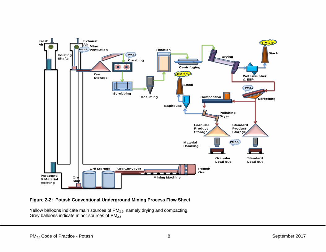
Figure 2-2: Potash Conventional Underground Mining Process Flow Sheet Yellow balloons indicate main sources of PM2.5, namely drying and compacting. Grey balloons indicate minor sources of PM2.5

PM2.5 Code of Practice - Potash 9 September 2017
2.2 Solution Mining
2.2.1 Solution Mining Subsurface Operations
This type of mining starts by the injection of fresh water through two injection wells directly into the underground ore body to dissolve the contained muriate of potash in situ. The impregnated brine is brought to the surface processing plant by the extraction well to remove the dissolved potassium chloride product.
2.2.2 Solution Mining Surface Operations
2.2.2.1 Evaporation
Where evaporation is employed, pumped brine returning from the underground caverns is at 45˚C and is saturated with NaCl and KCl. The next process step takes advantage of the characteristic of KCl whose solubility increases with an increase in brine temperature, and that of NaCl, whose solubility decreases with an increase in brine temperature. The brine is heated to approximately 100˚C, resulting in NaCl precipitating out (due to supersaturation) and the KCl becoming undersaturated. Water is then evaporated from the brine through a series of successive evaporators to raise the concentration of KCL to saturation, force more NaCl to precipitate out, to produce brine mostly saturated with KCl. The resulting brine is pumped to the crystallization circuit.
2.2.2.2 Crystallization
The most common crystallizers used in the potash industry are referred to as draft tube crystallizers. These crystallizers operate on the principle of gravity settling, and this method is referred to as forced crystallization. Draft tube crystallizers operate in series of from four to eight units. Each sequential crystallizer operates at a lower temperature and vapour pressure to precipitate out the KCl progressively. In the wintertime in Saskatchewan, often natural crystallization is implemented by pumping the brine directly to cooling ponds. As the brine cools and the water evaporates due to the large surface area, KCl again precipitates out, and then is dredged from the ponds and processed into potash product.
2.2.2.3 Remaining Surface Operations
Following this process, the remaining surface operations, namely debrining, drying, screening, and compacting are very similar to those used in conventional underground mining, as described above in section 2.1.2.

PM2.5 Code of Practice - Potash 10 September 2017
Boiler
Evaporation
Centrifuging
DryingStack
PM 2.5
PM 2.5
Stack
ScreeningCompaction
Granular Product Storage
Standard Product Storage
Standard Load-out
GranularLoad-out
Wet Scrubber & ESP
Baghouse
Material Handling
Crystallization
Submersible Pump
Brine Solution
Mining Wells Cooling Pond
Floating Dredge
Weak Brine
PM2.5
PM2.5
PolishingDryer
Winter Operation
Figure 2-3: Potash Solution Mining Process Flow Sheet Yellow balloons indicate main sources of PM2.5, namely drying and compacting. Grey balloons indicate minor sources of PM2.5

PM2.5 Code of Practice - Potash 11 September 2017
3. SOURCES OF PARTICULATE MATTER Sector data indicates that dryers generate roughly half of the sector Total Particulate Matter (TPM) emissions, compactors generate about a third, and remaining sources account for the rest. These estimated emissions categorized by source are shown in Table 3-1. Table 3-1: Characterization of Total Particulate Matter Emissions*
Source Category Estimated Contribution to TPM Emissions (%)
Dryers 49% Compaction 31% Fugitive 8% Loadout 7% Mine Exhaust 5% Total 100%
*Source: Hatch Consulting Engineering and Project Implementation. 2008. Environment Canada, Mining and Processing Division, Canadian Potash Mining Sector, Foundation Report- Final Report. As can be seen from Table 3-1, the main TPM emission sources are associated with drying and compacting activities. However, some of the lesser emission sources are not insignificant and must be considered as well. Therefore the main focus of this Code will be the optimum operation of the PM2.5 emission abatement equipment, and environmental management practices associated with all identified sources. The majority of PM2.5 emission sources from potash facilities in Canada are equipped with wet scrubbers for emission abatement. Emissions from wet scrubbers may contain water droplets and these water droplets can interfere with stack testing equipment designed for the measurement of PM2.5. Therefore the available PM2.5 data is not considered as reliable as that for TPM. Nevertheless, an approximate correlation normally exists between TPM and PM2.5 emissions. Accordingly the Code focuses on the major TPM emission sources identified in Table 3-2, and by extension the PM2.5 emissions from these sources should also be reasonably well controlled by the practices recommended by the Code. The emission sources associated with the mining and processing activities defined in Section 2.0 are identified and listed in table 3-2 below. The sources which are identified as sources of PM2.5 emissions are designated S1 to S8 for the purposes of identification in Table S-1: List of recommendations, and Section 4: Recommended PM2.5 emission control practices. Some of the activities described in section 2.0 are entirely wet processes, and are not sources of PM2.5 emissions. These activities, listed here, are consequently not included in Table 3-2:
• wet crushing; • scrubbing and removal of fine tailings; • flotation; • heavy media separation; and • debrining/centrifuging

PM2.5 Code of Practice - Potash 12 September 2017
Table 3-2 Sources (S) of PM2.5 Emissions by Activity Activity
PM2.5 Emissions Conventional Underground Mining
Solution Mining
Subsurface operations (S1)
N/A There are some PM2.5 emissions associated with mining underground. These emissions, from operations such as primary crushing, material handling, the use of diesel trucks, and from mine air heating fuel combustion, discharge to atmosphere through the production shaft. However, these emissions are minor compared to the other activities.
N/A Well drilling (S2)
Drilling of wells to develop a series of horizontal subsurface caverns to progressively extract the saturated solution requires drilling equipment. PM2.5 emissions may be associated with diesel engines used to run the drilling equipment. This is a relatively minor source within a facility.
Dry Crushing (S3) N/A Dry crushing generates some PM2.5 emissions, but this a relatively minor source within a facility.
Evaporation and Crystallization (S4)
Boilers are used to provide steam for these processes. Boiler fuel combustion exhaust contains some PM2.5 but is minor considering the fuel is natural gas.
Drying (S5) Drying generates PM2.5 emissions and these are controlled by dedicated dryer emission control devices, usually wet scrubbers and electrostatic precipitators.
Screening (S6) Screening can generate PM2.5 emissions but these are usually controlled as part of general area ventilation systems.
Compacting (S7) Compacting generates PM2.5 emissions and these are controlled by dedicated compactor emission control devices, usually baghouses.
Material Handling (S8)
Material handling operations generate PM2.5 emissions but are generally enclosed. Some points have control devices.
PM2.5 Code of Practice - Potash 13 September 2017
4. RECOMMENDED PM2.5 EMISSION CONTROL PRACTICES This section presents recommended best environmental practices and mitigation measures to control TPM and PM2.5 emissions from processes in the potash sector. The recommendations in this Code should be applied where and when appropriate based on the particular circumstances of each facility. The recommendations are categorized as follows: • Emission Control Devices
• Wet Scrubbers • Baghouses • Electrostatic Precipitators
• Emission Control Devices - general • Dryers and Compactors - Maintenance • Material Handling Practices • Environmental Management Practices.
Each recommendation listed in Table S-1 is followed by a brief discussion of the sources of particulate matter listed in the table.
4.1 Emission Control Devices
Emission control devices are defined as equipment, other than inherent process equipment, that is used to destroy or remove air pollutants from emission prior to the discharge to the atmosphere. Control devices that are typically used in the potash industry include wet scrubbers, baghouses (fabric filters), and electrostatic precipitators (ESPs). Since cyclones can be used to separate coarse particulate from the exhaust stream, they are often installed as a control device in series with one of the other devices, namely a scrubber, baghouse, or an ESP.
4.1.1 Wet Scrubbers
Wet scrubbers are classified as a wet particulate removal system. They remove particulates from an air stream by having them impinge on water droplets, or by becoming absorbed by the water. The water containing the particulate matter is then removed from the collector as a waste stream. There are several types of wet scrubbers available using different operating principles; four of the more common types are described below:
• Low-energy or gravity-spray-tower scrubbers are equipped with spray nozzles that atomize water and inject it into the rising exhaust gases. Dust particles are caught by the droplets through direct impaction, diffusion, or interception. Wastewater falls by gravity and is collected at the bottom of the scrubber. These types of scrubbers are moderately effective for particulate less than 10µ in size.
• Low-to-medium energy scrubbers use centrifugal force to spin the particulate against the wetted walls of the collector, where the particles are carried away by water introduced from the top. Collection efficiency is good for particles 5µ in size and above.
• Medium to high-energy scrubbers are of the packed-bed design. Beds of packing elements made from various materials break down the liquid flow into a high surface
PM2.5 Code of Practice - Potash 14 September 2017
area film to achieve maximum contact with the air stream moving up through the bed. Particles from the air stream are deposited on the bed, which are absorbed or washed down by the water for discharge at the bottom. This type of scrubber provides good efficiency for 10µ particles
• High-energy, or venturi scrubbers use a narrow throat (venturi) design to collect particulate under very high pressures. Water is injected with the exhaust gases and accelerated through the venturi section. The water is atomized and extreme turbulence promotes collisions between the water droplets and dust particulates in the throat. At the exit of the venturi section throat there is a high pressure drop, and particles are agglomerated with the droplets. The resulting gases then travel through a wetted elbow, a cyclonic section and finally a discharge hopper where the dirty water is discharged. Venturi scrubbers have a very high collection efficiency down to 1µ size particles.
RECOMMENDATION R01 – For venturi scrubbers, continuously monitor and record daily average gas flow rate and pressure drop, daily average brine/water flow rate, and daily average fan amperage; calculate L/G ratio daily. RECOMMENDATION R02 – For non-venturi scrubbers, continuously monitor and record daily average gas flow rate, brine/water flow rate, daily brine nozzle pressure, and daily average fan amperage; calculate L/G ratio daily. SOURCES TARGETED – S5, S6, S7, S8 As outlined in the CAM provisions, first establish the normal operating ranges of these devices during initial equipment installation and commissioning, periodic stack testing, performance testing, and/or periodic calibration as specified by the manufacturer. Pressure drop and liquid flow rate are often required to be monitored continuously for wet scrubbers. Any situation that increases the resistance to air movement through a device will increase the pressure drop and any situation that decreases the resistance to air movement will decrease the pressure drop. The flow rate of liquid (i.e., water or brine) to the wet scrubber is another simple operating parameter that can be monitored to ensure proper operation of the control device. An increased liquid flow rate may increase the size of droplets beyond the optimum size required to collect dust particles. It may also indicate the risk of erosion of the nozzle orifice. A decreased liquid flow rate may indicate a sub-optimum liquid contact, or sub-optimum droplet size. It may also indicate the risk of solids deposition or plugging in the liquid supply header or nozzles. Key attention should be paid to the nozzles and the water flow. Nozzles are typically set up for easy maintenance and they should be regularly checked because any plugging in the nozzles affects performance. Measuring liquid flow rate is also required as it is directly related to the liquid-to-gas (L/G) ratio. Since the exhaust gas flow rate is typically a constant value set by the fan speed on the ventilation system, the liquid flow rate is the simplest parameter to monitor to ensure that the optimum L/G ratio is being achieved. For dynamic ventilation systems, where exhaust gas flow may change significantly, the monitoring of liquid flow rate alone is insufficient so monitoring of exhaust gas flow is also required to ensure that the ventilation system is achieving the optimum L/G ratio. The fan current (fan amperage) should be monitored since it is proportional to power draw. In case the fan amperage decreases, it implies a blockage and in case the fan amperage

PM2.5 Code of Practice - Potash 15 September 2017
increases, it indicates that there is cold air going through the system. If a wet fan is involved, the total fan power is a function of how much water is being applied to the fan and the specific gravity (SG) of the brine. RECOMMENDATION R03 – Implement maintenance practices specific to wet scrubbers. SOURCES TARGETED – S5, S6, S7, S8 To ensure that the scrubbers are operated at their optimum design conditions, create and implement a maintenance program and schedule specific to the equipment based on manufacturing recommendations and site-specific requirements. The program may include:
o Inspecting for any possible air leak in the system and try to minimize the leakages;
o Performing visual inspecting for possible corrosion and plugging (e.g. spray nozzle for plugging in spray scrubbers);
o Cleaning filters on scrubber liquid inlet stream; and o Inspecting liquid recirculating pump, piping, and pressure gages for any
abnormality including leakage and plugging. RECOMMENDATION R04 – For those facilities equipped with wet scrubber recirculation monitoring systems, monitor and record changes in the brine specific gravity (SG) at regular intervals. SOURCES TARGETED – S5, S6, S7, S8 Establish the normal operating range in brine specific gravity for the scrubber recirculation system. Critical instrumentation to consider would be a SG monitor, which would indicate that the scrubber is maintaining a brine flow at the desired level. Changes in the SG indicate increasing concentration is occurring, which is an indicator of brine flow failure. A higher SG provides an early indication of reduced water flow and potential for plugging. It may also indicate potential reduced cyclone collection efficiency upstream (see 4.2.1).
4.1.2 Baghouses
A baghouse is a large filter housing filled with numerous long filter bags. Typically, the bags are cylindrical and made of fabric, although a flat bag or a pleated filter can also be used, and ceramic and sintered metal bags are available. In operation, dust-laden gases enter the chamber and pass through fabric bags that act as filter. A cake of solids is built up on the fabric surface, and it is this porous cake that conducts the particulate filtering. If the cake does not build up, the fine particulate present in the flue gas would penetrate into the fabric pores and quickly plug or blind the filter bag. With the cake, the blinding process is substantially slowed, and the bags may last from weeks to years, depending on the bag and particulate characteristics. The bags are usually cleaned by a reverse air, mechanical shaking, or a pulse jet. The pressure drop for a baghouse can range from 1 to 2.5 kPa (4 to 10 inches of water). RECOMMENDATION R05 – Continuously monitor the daily average pressure drop and average fan amperage of all baghouses. SOURCES TARGETED – S6, S7, S8,

PM2.5 Code of Practice - Potash 16 September 2017
Establish and record the baseline pressure drop of the baghouse being monitored on initial equipment installation and commissioning, periodic stack testing, performance testing, and/or periodic calibration as specified by the manufacturer. The static pressure drop establishes an indicator of the resistance provided by the fabric cloth and its collected layer of dust. It is also directly proportional to the exhaust gas volumetric flow rate. The ongoing operational pressure drop for each baghouse can be compared against baseline values (normally established during performance testing) to ensure proper baghouse operation. An increased static pressure drop generally indicates high gas flow rates, fabric blinding, or system cleaning problems.5 Conversely, a decreased static pressure drop is generally caused by reduced gas flow rates, excessive cleaning intensities or frequencies, reduced inlet PM loading, or possibly bag leakage.6 The continuous measurement of fan motor current through an ammeter is a method of determining the load that the fan must overcome to push (or pull) the exhaust gas through the fabric filter. This is an indicator of the resistance offered by the filters and the built-up dust. While increases in fan amperage generally indicate high exhaust gas flow, excessive cleaning, or possibly bag leakage, decreases in fan amperage generally imply reduced gas flow rates, or a higher degree of dust build-up. RECOMMENDATION R06 – For those facilities equipped with Baghouse Leak Detection Systems (BLDS) monitor their voltage continuously. SOURCE TARGETED – S7 Leaking or broken filters can lead to safety risks, reduced process efficiency, housekeeping and maintenance issues, damaged ventilation equipment, and environmental compliance violations. A recent compliance trend in the U.S. is to require baghouses to have a BLDS installed in the clean-air exhaust gas outlet to monitor significant changes in dust levels. The BLDS operates based on the triboelectric effect (also known as particle impingement or frictional electrification), which is the electrical charge transfer that occurs between two materials when one rubs or is impacted against the other. In operation, dust particles flowing in the air stream in the duct collide with the probe, generating an electrical charge. The electronics converts this charge to a particle emission signal voltage and continuously monitors and analyzes the signal during the baghouse operation. When the signal exceeds a pre-set PM level for a specified time delay, an alarm notifies the operators that a filter bag is leaking or has failed.7 RECOMMENDATION R07 – Implement maintenance practices specific to baghouses. SOURCES TARGETED – S6, S7, S8 Baghouses should be subject to a prescribed operations/maintenance routine that includes several components at prescribed frequencies: inspection and maintenance of hopper dust removal, compressed air supply and distribution, proper operation of cleaning cycles, functioning of bag cleaning mechanisms, bag integrity, and physical integrity of baghouse.
5 Fabric blinding is a flow restriction that occurs in fabric filter bags when dust becomes lodged deeply in the filter media causing a high differential pressure. This condition can occur eventually after long-term operation. 6 Summarized from U.S. EPA, Air Pollution Training Institute (APTI), SI445 – Introduction to Baseline Source Inspection Techniques, Lesson 12 - Level 2 Inspections, Fabric Filters. 7 Summarized from Bonine, S. and Otte, C., Monitor Technologies LLC, “How to detect leaking or broken filters with a triboelectric monitor”, Powder and Bulk Engineering, Jan 2010.

PM2.5 Code of Practice - Potash 17 September 2017
Furthermore, inspection of baghouses is critical in maintaining reliable long-term operation. There are several areas that require attention through routine inspection, including: • Daily check for indications of plugged pressure taps. The taps leading to the static pressure
gauges need to be free of material and liquids to function properly. The gauge face should be free of water and deposits and the gauge should fluctuate slightly each time one of the diaphragm valves activates;
• Monthly inspection of triboelectric probe for dust build-up. The triboelectric probe only generates voltage from direct impacts of dust on the probe’s metal surface. A visual inspection of the triboelectric probe is required to ensure that no dust has built up or caked on its surface;
• Inspection of fans. Fans need to be inspected periodically for wear, material build-up, and for corrosion. Continuous monitoring of vibration can provide ongoing information and periodic visual inspections can assess fan integrity;
• General inspection of equipment and maintenance. A baghouse inspection needs to cover all components of the system, including the compressed air equipment, bag cleaning mechanisms, and dust removal mechanisms from hoppers. On pulse-jet baghouses, inspections should focus on the conditions of the bags, cages, and compressed air delivery systems. On reverse air or shaker baghouses, inspections should focus on the bag tension and the status of the bag attachments at the tube sheet. For these baghouses, the majority of problems usually occur within the bottom 1-2 feet of the bags. Where possible, inspections should examine the clean side of the fabric filter to assess potential dust breakthrough. Fresh dust deposits on the clean side that are more than 1/8” deep indicate potential PM emission problems;
• Internal bag inspection. An internal inspection of the bags should be done semi-annually to assess their condition. The bag connections and tension need to be examined; and
• Bag replacement – Replacement schedules for bags should be determined based on manufacturer recommendations, and site-specific equipment and process conditions.
4.1.3 Electrostatic Precipitators
Particulate removal in an electrostatic precipitator (ESP) involves the discharge electrodes and the collection electrodes. In the first step, particulate is given an electrical charge by means of a high voltage (up to100,000 V) applied to the discharge electrodes. The particulate is then attracted to and precipitates on the collection electrodes by virtue of their opposite charge. For proper precipitation to occur, the drag force on the particles from the gas flow must be lower than the electrostatic force, and the residence time in the ESP must be sufficient for the particles to reach the collection electrodes. Gas velocity in an ESP typically ranges from 0.6 to 1.5 m/s, and gas residence time can be as high as 15 sec. RECOMMENDATION R08 – Continuously monitor the secondary current and secondary voltage of all electrostatic precipitators. As needed, monitor the spark rate. SOURCE TARGETED – S5 Establish the baseline voltages and spark rates on initial equipment installation and commissioning, performance testing, and/or periodic calibration as specified by the manufacturer. The secondary voltage provides an indication of the strength of the electrical field surrounding the discharge electrodes, which is related to the attraction force exerted on the particles in the exhaust gas. The secondary current is a measure of the quantity of dust that is diverted from its

PM2.5 Code of Practice - Potash 18 September 2017
flow path to contact and adhere to the discharge electrode. This parameter is related to the overall dust load being captured by the ESP’s discharge electrode. These two parameters should be monitored continuously for dry ESPs under the Compliance Assurance Monitoring provisions in U.S. EPA Maximum Achievable Control Technology (MACT) standards. Also, spark rate is a measure of how close to the maximum voltage at which an ESP is operating and provides an indicator of collection efficiency.8 The ESP’s performance can be evaluated by comparing the secondary currents, secondary voltages, and spark rates against baseline values. If the unit does not have secondary voltage meters, similar analyses can be conducted using the primary currents, primary voltages, secondary currents, and spark rates. Having a large spacing between discharge and collecting electrodes allows higher electric fields to be used, which tends to improve dust collection. To generate larger electric fields, however, power supplies must produce higher operating voltages.9 RECOMMENDATION R09 – Implement facility maintenance practices related to electrostatic precipitators. SOURCE TARGETED – S5 To ensure that ESPs are operated at their optimum design conditions, the following checklists can be applied: • Monitor electricity consumption, power voltage and amperes; • Check dust concentration at the exit of the ESP; • Perform visual inspections for the coated plates/tubes and wires with dust, and also possible
broken plates/tubes and wires; and • Verify that the equipment is operated within the appropriate operating range
4.2 Emission Control Devices - General
RECOMMENDATION R10 – Implement recordkeeping of monitoring, excursion evaluation and excursion correction of all emission control devices at significant sources. SOURCES TARGETED – S5, S7 Ongoing recordkeeping is important to determine the effectiveness of the Code, and to identify opportunities for improvement. When an excursion occurs, it is good practice to monitor the control device performance at a regular frequency interval appropriate to the control device and specific situation in the period after the excursion until it is corrected. It is also recommended to evaluate and correct the problems that have affected the control equipment in a formal manner. A quality improvement plan (QIP) is a formalized written plan that outlines the procedures used to evaluate problems that affect the performance of control equipment, and has two basic components:10 8 Summarized from U.S. EPA, APTI Virtual Classroom, SI 445 – Introduction to Baseline Source Inspection Techniques, Lesson 10 – Operation of Electrostatic Precipitators. 9 U.S. EPA, Air Pollution Control Cost Manual, Sixth Edition (EPA/452/B-02-001), 2002, Section 6, Chapter 3- PM Controls – Electrostatic Precipitators. 10 Summarized from U.S. EPA, Technical Guidance Document: Compliance Assurance Monitoring (CAM), Revised Draft (August 1998), p.2-38.

PM2.5 Code of Practice - Potash 19 September 2017
• Initial Investigation procedures to evaluate and determine the cause of control device performance problems. These usually contain a list of inspections, system operation verifications, and a parameter-monitoring schedule that must be initiated within a specified number of days from the date of the last excursion; and
• Modifications to enhance current CAM practices including the procedures that should be implemented to reduce the probability of a recurrence of the problem, and the schedule for making such improvements. Procedures might include: improved preventative maintenance practices; process operation changes; and appropriate improvements to control methods.
4.2.1 Cyclones
Cyclones separate solids from gas streams by centrifugal force. Cyclone separators are vertical, cylindrical vessels with a gas entrance designed to give a spiralling gas flow around and down the cyclone wall. Once the gas is in the cyclone, the downward spiralling flow of the gas stream imparts a centrifugal force on the particulate, which is thrown radically outward to the cyclone wall. When the particles hit the wall, much of their momentum is absorbed, and they fall to a cone-shaped section at the bottom of the cyclone. The particles are discharged out of the cone through a narrow neck, while the gas continues spinning along the wall inside the cylindrical vessel and exiting through a tube that is mounted in the center of the top of the cyclone.11 RECOMMENDATION R11 – Implement maintenance practices specifically related to cyclones. SOURCES TARGETED – S5, S6, S7, S8 The particle collection efficiency of cyclones depends on a number of factors, including the dimensions (length and diameter) of the cyclone, the inlet gas velocity, the particle size, and the dust concentration in the gas stream. Collection efficiency often rises when inlet gas velocity increases and when particle size and dust concentration increases. Also, smaller cyclones are usually more efficient than larger cyclones. The physical condition of the cyclone body also affects removal efficiency. Dents, riveted joints, and other surface irregularities can disrupt the vortex within the cyclone, thereby causing particles to bounce back into the centre of the cyclone instead of being concentrated near the cyclone wall. Air infiltration through the solids discharge valve, holes, or weld failures can also disrupt the vortex.12 Cyclones are the simplest piece of equipment among the PM removal systems, but the following actions can be taken to ensure that they are operated at their optimum conditions: - Perform visual inspections of all elements associated with cyclones (including airlock and
rotary valve device operation) as maintenance is being performed, and more frequently if needed due to equipment malfunction or process upsets.
4.3 Dryers and Compactors
RECOMMENDATION R12 – Ensure there are no leaks in the dryer air discharge system that would allow dust to escape. 11 Hatch Consulting Engineering. 2008. Environment Canada, Mining and Processing Division Canadian Potash Mining Sector Foundation Report. Final Report. 12 Summarized from U.S. EPA, APTI Virtual Classroom, SI 445 – Introduction to Baseline Source Inspection Techniques, Lesson 17 – Operations of Mechanical Collectors.
PM2.5 Code of Practice - Potash 20 September 2017
SOURCE TARGETED – S5 As part of normal operations, regularly inspect the drying equipment, including sealing joints and other sections of the air ducting to prevent dust from escaping. Initiate corrective actions accordingly. RECOMMENDATION R13 – Ensure that compactor hoods and ducting are fitted properly and have no cracks to prevent dust from escaping. SOURCE TARGETED – S7 As part of normal operations, regularly inspect the compacting equipment, including sealing joints and other sections of the air ducting to prevent dust from escaping. Initiate corrective actions accordingly.
4.4 Material Handling Practices
Material handling operations are commonly found in any solid fertilizer production operation, and these operations generally consist of storage (piles, silos, bins) and the transfer operations (conveyor belts, elevators, gravity drop, pneumatic transfer, etc.). Material handling operations generate PM2.5 emissions but are usually enclosed, and some points have control devices. RECOMMENDATION R14 – Optimize material handling, storage, and conveying practices. SOURCE TARGETED – S8 Particulate matter emission controls for material handling involves physical practices. Weather monitoring and suspension of operations during severe/adverse weather conditions (mainly high wind speeds) can decrease particulate emissions. Point sources in the materials handling processes can be designed to reduce particulate emissions. More specifically, conveyors can be designed to reduce particulate emissions in various ways, such as: • Enclosed; side wind guards, covers; • Reduced drop heights at transfer points; • Suitable speed; • Loading of belt not to edges; and • Maintenance and operation of conventional conveyors. Loading, unloading and transfer points can be optimized to minimize emissions by reducing drop heights. Minimizing drop heights and regular cleanings of front-end loaders would also reduce emissions.
4.5 Environmental Management Practices
RECOMMENDATION R15 – Implement broad-based best practices for general environmental management. SOURCES TARGETED – S1 through S8 There are a number of reference materials that speak to good environmental practice, such as:

PM2.5 Code of Practice - Potash 21 September 2017
• ISO 14000 Environment Management Systems, • Environment Canada’s Environmental Code of Practice for Metal Mines, 2009, and • Environmental Aspects of Phosphate and Potash Mining, United Nations Environment
Program (UNEP), 2001.

PM2.5 Code of Practice - Potash 22 September 2017
5. IMPLEMENTATION OF THE CODE OF PRACTICE Implementing the Code should result in controlling and minimizing particulate matter and PM2.5 emissions for the facilities concerned. Successfully achieving this includes an implementation plan and self-monitoring by the facilities. This section outlines an approach to developing individual work methods, applying them and following up on them on a regular basis to improve or maintain performance (Figure 5-1). The facility concerned could take a different approach depending on its needs and structure.
Develop improved procedures based on the Code of Practice and current work methods
Analyze methods currently used to monitor PM2.5 emission abatement equipment.
Implementation of improved monitoring procedures by employees
Develop protocol for auditing the effectiveness of improved monitoring of PM2.5 emission abatement equipment
Audit the effectiveness of improved monitoring
Develop corrective measures as needed
Establish baseline operating ranges of PM2.5 monitoring devices.
Prepare training plan for affected employees
Inform affected employees of improved monitoring procedures based on training plan
Planning
Application
Figure 5-1: General Approach to Implementing Best Practices by a Potash Facility Subject to the Code of Practice
5.1 Initial Planning
It is advisable to analyze the current situation in the plant to carry out individual procedures based on the recommendations of the Code. After the new practices are implemented, it is important to ensure that they are effective and are yielding the expected results. Such analysis

PM2.5 Code of Practice - Potash 23 September 2017
should follow a predetermined protocol for auditing on-site activities relating to the new practices.
5.1.1 Analysis of Current Situation
The purpose of the initial analysis is to obtain not only relevant information and data on the technologies in place, but especially the operating, control and maintenance methods of the plant in question. A questionnaire or checklist would be an appropriate tool for this task.
5.1.2 Development of Custom Procedures
Based on the results of the initial analysis, opportunities for improvement in the monitoring of PM2.5 emissions abatement equipment could be identified. The facility could thus develop their own procedures (in a custom document) on the basis of recommendations provided in the Code and the plant’s unique characteristics. The development of custom procedures may mean adopting practices that are not mentioned in the Code but would nonetheless control PM2.5 emissions, according to the facility’s analysis. The Code is not restrictive in this regard. Consultation with employees should facilitate the implementation of the new procedures at the appropriate time and prevent problems that might arise if employees are not consulted.
5.1.3 Employee Training Plan
From a strategic standpoint, it is advisable to prepare a training plan for employees required to modify or implement new procedures. Successful training depends on properly prepared documents and training as well as on the standardization of the new procedures.
5.1.4 Protocol for Reviewing the Effectiveness of Custom Procedures
New or modified procedures should be monitored regularly to ensure they are yielding the desired results. A review should preferably be carried out using a protocol developed alongside the procedures. The best approach is to prepare a checklist with qualitative and quantitative questions to assess the current situation properly. Where applicable, this checklist should contain the baseline ranges established following the initial analysis. This protocol should also provide for a consistent review methodology. Annex A offers a Recordkeeping Template that facilities may choose to use for this purpose. Baseline operating ranges of monitoring and control devices are typically established during initial equipment installation and commissioning, periodic stack testing, performance testing, and/or periodic calibration as specified by the manufacturer.
5.2 Implementation of the Code
It is to be expected that the results of new procedures will not be optimal at the beginning and that corrections will probably have to be made after the initial review. This review–correction cycle should be applied periodically even when the level of monitoring is deemed satisfactory by the facility.
5.2.1 Performance Review of Improved Procedures
It is recommended that a review of the new procedures be carried out quite frequently at the beginning (e.g., 6–12 months) according to the protocol developed for that purpose (Section

PM2.5 Code of Practice - Potash 24 September 2017
5.1.4) to fine-tune the procedures. When all the procedures are diligently followed by the staff concerned, reviews could be undertaken less frequently. They will nonetheless have to be maintained at a reasonable frequency for quality control purposes. Each potash facility using the Code should retain, for a reasonable period of time, all this recorded information which will demonstrate that the objectives of this Code are being met. This log will help determine the overall effectiveness of the Code and will identify future opportunities for improvement.
5.2.2 Reporting
To assess the degree of implementation of this Code and to monitor levels of PM2.5 emissions, potash facilities will annually submit total emissions of PM2.5 by source, as well as the methodology used to quantify those emissions, to Environment and Climate Change Canada. For those facilities in operation prior to December 31, 2017,
• The first annual report for reporting year 2017 (Jan 1 to Dec 31) will be due on or before June 1, 2018.
• For reporting year 2018 (Jan 1 to Dec 31), facilities will submit details, on or before June 1 of 2019, regarding implementation of the recommendations in this Code, and every two years thereafter.
For those facilities that commence operations after December 31, 2017,
• Annual reports will be due on or before June 1 of the year immediately following the first full or partial calendar year of operation.
• Details regarding the implementation of the recommendations in this code will be due on or before June 1 of the second year immediately following the first full or partial calendar year of operation, and every two years thereafter.
Reports are to be provided to Environment and Climate Change Canada to the following email address: [email protected] A sample of the information that would be included in the reports is provided in Annex B. Facilities should use standard methods to quantify PM2.5 emissions, such as those listed below. Where the use of these methods is not possible or practical, facilities may use quantification methodologies currently used to report to federal or provincial regulatory programs.
• Measurement of Releases of Particulate from Stationary Sources. Environment Canada, reference Method EPS 1/RM/8, December, 1993.
• Reference Method for Source Testing: Measurement of Releases of Fine Particulate Matter from Stationary Sources. Environment Canada, Method G: Determination of Filterable PM2.5 and Filterable Particulate Matter, reference Method EPS 1/RM/55, December 2013

PM2.5 Code of Practice - Potash 25 September 2017
• Reference Method for Source Testing: Measurement of Releases of Fine Particulate
Matter from Stationary Sources. Environment Canada, Method H: Determination of Condensable Particulate Matter (CPM), reference Method EPS 1/RM/55, December 2013
• U.S. Environmental Protection Agency. Federal Reference Methods 201a and 202. Methods for Measurements of Filterable PM10 and PM2.5 and Measurement of Condensable PM Emissions from Stationary Sources, 40 CFR Part 51.

PM2.5 Code of Practice - Potash 26 September 2017
NOMENCLATURE ABBREVIATIONS AQMS Air Quality Management System BLDS Baghouse Leak Detection Systems BLIERs Base-level Industrial Emissions Requirements CAM Compliance Assurance Monitoring CCME Canadian Council of Ministers of the Environment ESP Electrostatic Precipitator Fe3O4 Iron (II, III) Oxide (magnetite) MACT Maximum Achievable Control Technology KCl Potassium Chloride (muriate of potash or sylvite) NaCl Sodium Chloride (halite) PCS Potash Corporation of Saskatchewan PM10 Particulate Matter (under 10 microns) PM2.5 Fine Particulate Matter (under 2.5 microns) QIP Quality Improvement Plan SG Specific Gravity SO2 Sulphur Dioxide TPM Total Particulate Matter U.S. EPA United States Environmental Protection Agency GLOSSARY Baghouse (Fabric Collector) Type of dust collector that uses large filter housing filled with
numerous long filter bags to capture particles contained in gas. BLDS Baghouse Leak Detection System: A stainless steel probe
inserted into the middle of the clean air duct of a baghouse and a linkage to the sensing electronics to detect leaking or broken filters.
Brine Brine is a solution of salt, usually sodium chloride, in water. Centrifuging (Debrining) Screen-bowl centrifuges are used to remove water (debrine)
from the flotation concentrates. Compacting Process used to produce larger, coarse and granular particule
sizes in the potash sector.
PM2.5 Code of Practice - Potash 27 September 2017
Conventional underground The process of tunneling below the earth and removing ore Mining deposits from the subsurface. Crushing Process used in underground mining that reduces the particle
size distribution of large mineral ore pieces to finer pieces. Crystallization Process used to produce soluble grade muriate of potash,
which separates minor impurities of sodium chloride from potash fines of greater purity.
Cyclones PM control devices used to separate solids from gas streams by
centrifugal force, which are suitable for high dust loadings and removal of coarse particulate fractions.
Drying Thermal process that removes the remaining moisture content
and burns residual organic reagents (especially flotation amine) from the centrifuging process.
Dust collector Processing unit designed to capture most particles contained in
gas. Electrostatic Precipitator (ESP) A large chamber filled with long, vertical electrodes that uses
magnetic forces to separate suspended particulate matter from the gas stream.
Excursion A deviation of one or more operating, maintenance or other
parameters outside of normal operating conditions that materially reduce the PM reduction efficiency of the control equipment below its design control efficiency or best possible control efficiency expected for the normal operating conditions for that site.
Evaporation Solution mining process used prior to crystallization where the
brine is heated up to approximately 100 0C, making it undersaturated in KCl and supersaturated in NaCl, to precipitate out the NaCl.
Froth Flotation Process used to achieve primary separation of potash ore (KCl)
from halite (NaCl) and gangue materials. Chemicals, amine renders KCl hydrophobic (attach to air bubbles) while leaving NaCl hydrophilic.
Glazing Post-treatment step where the final products are mixed with a
small amount of water and dried again to obtain a hard outer coating, to fill cracks in the particles, to strengthen the compacted particules, and to eliminate sharp corners.
Heavy Media Separation Process to produce an intermediate-sized product (~1.7 mm) at
two specific facilities. In this process, a mix of particles containing KCl and NaCl in this size range are introduced into a brine to which magnetite (Fe3O4) was added. The magnetite increases the brine’s specific gravity, which during centrifuging

PM2.5 Code of Practice - Potash 28 September 2017
floats the KCl to the surface, while NaCl and other impurities drop out. The KCl is then sent to be debrined.
Liquid-to-Gas (L/G) ratio Measure of water (or brine) flow rate through the scrubber per
unit volume of exhaust gas; indicates scrubber collection efficiency.
Prairie Evaporite Deposit An area beneath the southern plains fof Saskatchewan where a
significant portion of the potash reserves is located. Removal of Fine Tailings Process of removing insoluble minerals (fine tailings) that are
part of the brine used in scrubbing. Screening Mechanical process of sizing dried potash into classified
fractions. Scrubbing Process of adding brine to crushed ore in agitaded tank cells to
remove clay and other insoluble impurities. Spark Rate A measure of how close to the maximum voltage an ESP is
operating; provides an indicator of collection efficiency. Venturi Wet Scrubber High-velocity and high static pressure drop gas cleaning system
that atomizes water/brine to achieve high collection efficiencies.
Wet Scrubber Wet particulate removal system where the polluted gas stream
is brought into contact with the scrubbing liquid to remove air pollutants.

PM2.5 Code of Practice - Potash 29 September 2017
REFERENCES Cheminfo Services Inc. 2013. Particulate Matter Emissions in the Canadian Potash Sector. Final Report. Hatch , Consulting Engineering and Project Implementation. 2008. Potash Environment Canada, Mining and Processing Division Canadian Potash Mining Sector Foundation Report. Potash Foundation Final Report. AMEC Engineering & Construction Services Limited (1990) Potash Processing in Saskatchewan – A Review of Process Technologies
ASTM D-6216-07 (2007) Standard Practice for Opacity Monitor Manufacturers to Certify Conformance with Design and Performance Specifications
Biotechnology and Environmental Engineering R & D Ltd (2004) 3.3 Potash: 3.3.1 Mineralogy and Mining Techniques. Bonine, S. and Otte, C., Monitor Technologies LLC, (2010) How to detect leaking or broken filters with a triboelectric monitor”, Powder and Bulk Engineering CED Engineering (1998) Baghouses and Filters for Particulate Matter Control Cheminfo Services Inc. (2009) Technical Evaluation of Options for Air Pollution Control of Emissions from the Integrated Iron & Steel and Non-Integrated Steel Sub-sectors, Part One – VOC and PM, Final Report. Chevron Phillips Chemical Company LLC (2012) Introduction to Mineral Processing: Froth Flotation Energy Information Administration (1994) Longwall Mining Environment Canada, (1993) Standard Reference Methods for Source Testing: Measurement of Emissions of Particulate from Stationary Sources, Reference Method EPS 1/RM/8. GEA Barr-Rosin (2012) Solids Drying GEA Process Engineering Inc. (2012) Fluid Bed Drying – Fundamentals Marama, PM CEMS Webinar (Oct. 6, 2011) TEOM Technology Midwest Research Institute (2000) Current Knowledge of Particulate Matter (PM) Continuous Emission Monitoring, US Environmental Protection Agency, Office of Air Quality Planning and Standards, Emission Monitoring and Analysis Division, Research Triangle Park, EPA-454/R-00-039 Natural Resources Canada (2009) Canadian Minerals Yearbook: Potash Partha Das Sharma (2008) Sublevel Caving Technique

PM2.5 Code of Practice - Potash 30 September 2017
U.S. EPA, Air Pollution Control Cost Manual, Sixth Edition (EPA/452/B-02-001), 2002, Section 6 Particulate Matter Controls. U.S. EPA, Air Pollution Training Institute (APTI), SI:445 - Introduction to Baseline Source Inspection Techniques, Lesson 12 - Level 2 Inspections. U.S. EPA, Air Pollution Training Institute (APTI), SI:445 - Introduction to Baseline Source Inspection Techniques, Lesson 10 - Operation of Electrostatic Precipitators U.S. EPA, Air Pollution Training Institute (APTI), SI:445 - Introduction to Baseline Source Inspection Techniques, Lesson 17 - Operation of Mechanical Collectors U.S. EPA, Air Pollution Training Institute (APTI), SI:445 - Introduction to Baseline Source Inspection Techniques, Lesson 12 - Level 1 Inspections U.S. EPA, Air Pollution Training Institute (APTI), SI:445 - Introduction to Baseline Source Inspection Techniques, Lesson 10 - Operation of Electrostatic Precipitators U.S. EPA, CEMS Performance Specification 1 for Opacity U.S. EPA (2003) National Emission Standards for Hazardous Air Pollutants: Taconite Iron Ore Processing; Final Rule (40 CFR Part 63 RRRRR), Oct 29, 2003. U.S. EPA, (August 1998) Technical Guidance Document: Compliance Assurance Monitoring (CAM), Revised Draft U.S. EPA, Test Method 201A: Determination of PM10 and PM2.5 Emissions from Stationary Sources (Constant Sampling Rate Procedure) U.S. EPA, Test Method 5: Determination of Particulate Matter Emissions from Stationary Sources Washington State University (1994) Potash Crystallization Environment Canada. 2009. Environmental Code of Practice for Metal Mines. Mining and Processing Division. 1st Edition, 2009. Environment Canada, Environmental Code of Practice for Base Metals Smelters and Refineries – CEPA 1999 Code of Practice, March 2006, www.ec.gc.ca/lcpe-cepa/documents/codes/famc-bmsr/famc-bmsr_eng.pdf. Environment Canada, Environmental Code of Practice for Integrated Steel Mills – CEPA 1999 Code of Practice, 1st Edition, March 2001, www.ec.gc.ca/lcpe-cepa/documents/codes/ai-ism/ai-ism-eng.pdf. Environment Canada, Environmental Code of Practice for Non-Integrated Steel Mills – CEPA 1999 Code of Practice, 1st Edition, March 2001, www.ec.gc.ca/lcpe-cepa/documents/codes/ani-nism/ani-nism-eng.pdf. Environment Canada, National Pollutant Release Inventory (NPRI), www.ec.gc.ca/inrp-npri. Ministry of the Economy. 2012. Potash Mining Suppy Chain Requirement Guide. Greenfield Mine Lifecycle Costs. Hatch Limited.

PM2.5 Code of Practice - Potash 31 September 2017
Perucca, C.F. 2001. Potash Processing in Saskatchewan. A Review of Process Technologies. Klein, O.M., and Reid, K.W., Goldsmith, E.L. 1994. Pollution Control in Fertilizer Production. Edited by C.A. Hodge & N.N. Popovich. Chapter 27, Air Emissions at KCl Facilities.

PM2.5 Code of Practice - Potash 32 September 2017
ANNEX A Recordkeeping Template (refer to section 5.1.4) Facilities may choose to use this template to assess initial conditions and for review purposes. The table lists the Code’s recommendations with associated parameters. Facility Contact information
Recommendation
Monitoring Frequency
Normal operating range
Daily* Value recorded
Date
Indicate whether reading is within range
* unless otherwise specified
Y N
R01 - venturi scrubbers
gas flow rate continuous
gas pressure drop
continuous
water/brine flow rate continuous
fan amperage continuous
L/G ratio calculate daily
R02 - non-venturi scrubbers
gas flow rate
continuous
water/brine flow rate continuous
nozzle pressure continuous consult
manuf consult manuf
fan amperage continuous
L/G ratio calculate daily
R04 - brine recirculating systems
brine specific gravity
at regular intervals
R05 - baghouses
gas pressure drop
continuous

PM2.5 Code of Practice - Potash 33 September 2017
fan amperage Continuous
R06 - baghouses
BLDS voltage
Continuous
R08 - ESPs
secondary current
Continuous
secondary voltage Continuous
spark rate Weekly consult manuf
consult manuf
R10 Excursions - Emission Control Device Excursion noted on device
Excursion correction
Specify device and excursion Date Type of correction
implemented Date
Maintenance Practices Status of system or device
Follow-up actions if required Date
R03 - wet scrubbers
system leaks corrosion pump, piping, pressure gauges
R07 - baghouses
pressure taps triboelectric probe fans bag cleaning mechanism
bags

PM2.5 Code of Practice - Potash 34 September 2017
R9 - ESPs power consumption
dust concentration at exit
plates/tubes/wires R11 - cyclones
dust collection at exit
corrosion, plugging cyclone design air lock
R12 - general facility
dryer air discharge system
R13 - general facility
compactor hoods and ducting
R14- general facility
materials handling processes
R15 Environmental Management Practices - general facility
Status of implementation Date
Environmental management practices - list

PM2.5 Code of Practice - Potash 35 September 2017
Annex B: Sample Report Template Part A: Emissions Reporting Facilities are asked to report their PM2.5 emissions as well as the methodology used to quantify those emissions in a table similar to the format provided below. Annual Reporting of PM2.5 Emissions Source of PM2.5 Annual quantity
of PM2.5 emitted (tonnes)
Quantification Methodology
Stack/Dryers Stack/Compactors Storage or Handling Fugitive Other non-point Road Dust Total quantitiy emitted (t) Part B: Reporting on the Implementation of the Code of Practice The following provides a list of sample questions which may be used to demonstrate facility progress towards implementation of the Code. For each recommendation in this Code, facilities are asked to provide answers to the following questions:
• Has the facility implemented the recommendation? • If the answer is yes, please describe how the facility has implemented the
recommendation. • If the answer is no, please explain whether the facility plans to implement the
recommendation. • If the facility plans to implement the recommendation at a later date, please explain what
will be done and by what date. • If the facility does not plan to implement the recommendation, please explain why and
also describe what practices the facility has in place to ensure the optimal operation of the specified control device.
Facilities should provide, if needed, any additional information on each recommendation.

PM2.5 Code of Practice - Potash 36 September 2017
Part C: Declaration A declaration, as per the example below, is to be attached to each report. I declare that this report is true, accurate and complete. _________________________________ ____________________________ Operator’s name (please print) Position title _________________________________ ___________________________ Telephone Email ________________________________ ___________________________ Operator’s signature Date of Signature