code requirements for the evaluation and design of … conference... · that the pipe designer may...
TRANSCRIPT

© IIAR 2017 1
Abstract
Placing ammonia piping and equipment on the roof of a building presents additional loading challenges that the pipe designer may not typically address. General loading concerns including; service loads, gravity loading, and where applicable seismic loads, should be addressed for any above ground pipe system. However, wind loading on rooftops or exterior exposed piping can present a unique design challenge for the pipe systems and the support components. This paper will review current code requirements specifically associated with wind and seismic loading on rooftop applications. Even if addressing this loading is outside the scope of work, a knowledge of the requirements can aid in better system coordination and design.
Technical Paper #4
Code Requirements for the Evaluation and Design of
Rooftop Equipment Supports
Robb N. Davis, P.E., Sr. Engineer, MIRO Industries [email protected]
801-839-2962


Technical Paper #4 © IIAR 2017 3
Code Requirements for the Evaluation and Design of Rooftop Equipment Supports
Introduction
Placing ammonia piping and other utility lines and equipment on the roof is common
practice with many reasons and advantages. For projects involving retrofit or addition
of new equipment, the roof is often the only place with adequate access and the
clearest path to run mechanical, electrical, plumbing, and communication lines.
However, rooftop installation exposes the equipment to other conditions that are not
a factor when placed inside of the building envelope. Adopted codes and standards
establish a minimum basis for the design and installation of building structures,
components, and systems. Minimum requirements are a means to safeguard the
public health, safety, and general welfare of building occupants and the community
as a whole.
Currently, the most widely adopted code throughout the United States is the
International Code Council’s (ICC) International Code Family (2015). Many
jurisdictions have adopted either the code family as a whole or have amended the
code based on conditions within the jurisdiction. This paper intends to discuss the
sections of the International Code Family that specifically address the requirements
for supporting refrigeration equipment on the roof of a building and how the
applicable loading requirements affect the design of the supporting elements. This
paper is not intended to be an all-inclusive study of the many dynamic factors that
affect the selection, design, and installation of refrigerant system piping. Some local
amendments to the ICC code family will be discussed, but the design professional
is responsible for ensuring all code requirements and guidelines for the applicable
project and jurisdiction are met.
Trade or industry standards such as the ANSI/IIAR Standard 2-(2014), ASHRAE
Standard 15-(2016), etc. identify standard practices that are then either referenced or
specifically cited within the ICC codes. Often these industry standards contain more
specific and stringent requirements for the design of the piping system and play a
key role in the establishment and modification to adopted codes. As such the volume
4 © IIAR 2017 Technical Paper #4
2017 IIAR Natural Refrigeration Conference & Heavy Equipment Expo, San Antonio, TX
of literature referenced in the International Code Family can be overwhelming to
any design professional. For the intent of this paper we will focus primarily on the
following codes:
• 2015 International Mechanical Code (IMC),
• 2015 International Building Code (IBC),
• ASCE 7-10 (2010) “Minimum Design Loads for Buildings and Other Structures.”
These three referenced documents are the most generally accepted and current codes
containing the basis for the design for rooftop equipment supports.
2015 International Mechanical Code
Our journey will begin with the 2015 International Mechanical Code. Chapter 11 is
dedicated to refrigeration, providing general requirements, system requirements,
system classifications, application requirements, ventilation and detection
requirements, refrigerant piping requirements, and testing/inspection requirements.
Section 1107, “Refrigerant Piping,” contains requirements for the type of pipe that
can be used for refrigerant systems and where the pipe can or cannot be located, but
the way to properly support the pipe is not discussed. For supporting requirements
we need to jump back to Chapter 3, “General Regulations.” Chapter 3 Section 301.1
begins with the blanket statement, “This chapter shall govern the approval and
installation of all equipment and appliances that comprise parts of the building
mechanical systems regulated by this code …..” Section 301 also contains specific
requirement for other applicable loading conditions that are to be considered on
mechanical systems. Section 301.15, “Wind Resistance,” states that “Mechanical
equipment, appliances and supports that are exposed to wind shall be designed and
installed to resist the wind pressures determined in accordance with the International
Building Code.” The phrases “exposed to wind” and “shall be” are key. Is there ever
a situation where a pipe on an open roof is not “exposed to wind”? Section 301.18,
“Seismic Resistance,” states “Where earthquake loads are applicable in accordance

Technical Paper #4 © IIAR 2017 5
Code Requirements for the Evaluation and Design of Rooftop Equipment Supports
with the International Building Code, mechanical system supports shall be designed
and installed for the seismic forces in accordance with the International Building
Code.” You will notice the difference in wording here as opposed to the wind loading
requirements. The phrase “where earthquake loads are applicable” indicates that
these forces may not apply where the wind loading phrase “that are exposed to
wind shall be” does not leave any wiggle room. Finally, before we jump to the
International Building Code, it is worth visiting Section 305, “Pipe Support.” This
section briefly covers pipe hanger and attachment methods and maximum support
intervals. Section 305.4 and Table 305.4 list maximum horizontal and vertical spacing
of supports for various piping materials. The maximum support spacing will later be
factored into the design of the supports to resist the required wind and applicable
seismic loading.
2015 International Building Code and ASCE 7-10
Now jumping into the 2015 International Building Code we will go directly to
Chapter 16, “Structural Design.” Some building parameters must first be established
before subsequent loading requirements can be determined. If the project is new
construction, the following parameters will be established by the project structural
engineer of record. If your project deals with equipment on an existing building this
information may not be as readily available. However, with a little information about
the building’s location, intended use, the height of the roof, an understanding of the
roof cross-section, and information about the pipe or equipment to be supported, the
applicable wind and seismic loading requirements can be established.
Building Risk Category
First we need to establish a risk category for the building. Table 1604.5 in Chapter 16
contains a list of building uses with the appropriate risk category. Four risk categories

6 © IIAR 2017 Technical Paper #4
2017 IIAR Natural Refrigeration Conference & Heavy Equipment Expo, San Antonio, TX
are based on the use and occupancy load of the building structure. Category I
buildings have a low hazard to human life in the event of a failure. These are
typically limited to agricultural facilities, temporary facilities, and storage facilities.
Category II buildings are those that do not fall into one of the other three categories.
Category III buildings pose a significant risk to human life in the event of a failure.
These are typically buildings with high occupancies where groups of people gather;
facilities where the occupants are confined or unable to exit the facility easily; and
buildings that do not fall into Category IV but have a potential to cause significant
disruption to daily civilian life, including economic loss or threat to public health and
safety. Category IV structures are deemed essential facilities that need to remain open
and functional. These facilities include emergency treatment facilities, first responder
facilities, designated emergency shelters, critical government facilities, and facilities
that contain significant quantities of hazardous materials.
Buildings utilizing ammonia refrigeration could be classified into any one of these
categories. A cold storage facility based on very low occupancy load could fall into
Category I, but when accounting for the volume of ammonia used in the refrigerant
system, it could also be elevated to a Category IV structure by the local jurisdiction
if a catastrophic failure of the system were determined to be a sufficient threat
to public health and safety. The owner of the facility could also dictate that the
building be designed to the elevated requirements of Category III or IV as a means to
mitigate risk associated with failure. Systems that are not found to contain sufficient
quantities of ammonia would be categorized based on use and occupancy guidelines
per Table 1604.5 of the IBC.
Load Combinations
With the building risk category established we can move on to establishing required
design loads. Rather than trying to group all loading together, multiple different
load combinations are established. Two design methods are included in Section

Technical Paper #4 © IIAR 2017 7
Code Requirements for the Evaluation and Design of Rooftop Equipment Supports
1605, “Load Combinations.” Strength design (or load and resistance factor design)
and allowable stress design are the two most commonly used combinations. Either
method can be used as long as the design is consistent throughout. Other items
to consider in the design of any component include serviceability factors such as
deflection limits or other visual or functional considerations. General loads included
in the load combinations include dead loads (D), live loads (L), snow (S) or rain (R)
loads, flood loads (F), lateral earth pressure loads (H), wind loads (W), seismic loads
(E), and in some instances ice loading. Of all these loads, we will quickly discuss
dead loads and dive more into the specifics of wind and seismic loading. Other
loads may also contribute to the design of the pipe support racks, but dead, wind,
and seismic loads are typically controlling factors. In regions prone to freezing rain
or atmospheric ice loading, the potential for increased design consideration is also
warranted.
Dead Loads
Dead loads consist of the weight of all materials. Fixed service equipment typically
falls into the dead load category as it is constant to the structure. For pipe loading,
one may need to consider both wet and dry pipe conditions if the pipe is to be
drained for any extended period of time. The weight of the support frame must also
be factored into the design and specifically into the reactions that will need to be
transferred through to the roof structure.
Wind Loads
The International Building Code does not emphasize a requirement for wind loading
on rooftop equipment, but some key requirements in Section 1609 of the IBC must be
addressed.

8 © IIAR 2017 Technical Paper #4
2017 IIAR Natural Refrigeration Conference & Heavy Equipment Expo, San Antonio, TX
The first paragraph of Section 1609.1, “Application,” has the following requirement:
“Decreases in wind loads shall not be made for the effect of shielding by other
structures.” Strictly interpreted, this blanket statement eliminates any potential to
reduce or eliminate wind loading where applicable. Through the 2004 and 2005
hurricane seasons, significant damage was observed due to improper attachment of
rooftop equipment. A study titled “Rooftop Equipment Wind Load and its Mitigation
for Buildings in Hurricane Prone Regions”(2007) was completed in partnership with
the International Hurricane Research Center and Florida International University. The
study evaluated the potential reduction to wind loading on rooftop equipment via
properly designed and installed wind screens. While the study reported significant
reduction in wind loading on the shielded rooftop equipment, additional studies
and revisions to the text of the code will be required before such reductions are
allowed. In contrast, FEMA produced a document titled “Attachment of Rooftop
Equipment in High-Wind Regions” with the findings of its Hurricane Katrina
Recovery Assessment stating that “Equipment screens around rooftop equipment are
frequently blown away. Equipment screens should be designed to resist the wind
loads derived from ASCE 7. Note: The extent that screens may reduce increased wind
loads on equipment is unknown. Therefore, the equipment behind screens should be
designed to resist the loads previously noted.” The FEMA report coincides with the
requirement in the IBC that decreases in wind loads shall not be made for the effects
of shielding by other structures.
Section 1609.1.1 of the IBC, “Determination of Wind Loads,” states that “Wind loads
on every building or structure shall be determined in accordance with Chapters 26 to
30 of ASCE 7 or provisions of the alternative all-heights method in Section 1609.6.”
However, the alternative all-heights method in Section 1609.6 requires certain
conditions be met to qualify. Condition #5 specifically excludes this method for
rooftop equipment, thus requiring the use of ASCE 7.
The wind loading chapters for the 2010 edition of ASCE 7 were reorganized and
modified. This change had a fairly significant impact on wind loading to rooftop

Technical Paper #4 © IIAR 2017 9
Code Requirements for the Evaluation and Design of Rooftop Equipment Supports
equipment. The two paragraphs in previous editions of the standard addressing wind
loading on rooftop equipment are now better defined and addressed in Chapter 29,
“Wind Loads on Other Structures and Building Appurtenances.” The process for
determining the basic wind speed changed significantly, and for the first time vertical
wind uplift loading was included in the main body of the standard. Previously, uplift
was mentioned in the commentary of the code with the note “The consensus of the
committee is that uplift forces may be a significant fraction of the horizontal force.
Hence, uplift load should also be considered by the designer.” A few exemptions are
also cited in subsequent paragraphs of the code but none apply to rooftop equipment
or equipment supports.
With the building risk category previously determined, a basic wind speed, V, is
determined based on Figures 1609.3(1, 2, or 3) of the IBC or Figures 26.5-1(A, B, or
C) in ASCE 7. Most of the country falls within a basic wind speed range of 105 mph
3-s gust to 120 mph 3-s gust depending on the building risk category. Along the east
coast and the gulf coast, wind speed can be as high as 200 mph 3-s gusts. A valuable
tool in determining basic wind speeds was prepared by the Redwood City, California,
based Applied Technology Council’s (ATC) Windspeed by Location website (http://
windspeed.atcouncil.org/). The site allows users to enter an address or latitude
and longitude coordinates to determine the appropriate basic wind speed. Users are
responsible for verifying that the information generated is valid, and in some “special
wind regions” wind loads are to be provided by the authority having jurisdiction. The
report generated by the ATC website is much more user friendly and easily verified
by cross checking on the letter size maps presented in the IBC and ASCE 7.
With the basic design wind speed and some other site-specific parameters including
wind directionality factor (Kd), velocity pressure exposure coefficient (Kz), and
topographic factor (Kzt), which are pulled from tables in ASCE 7, the basic wind
speed is converted to a velocity pressure via Equation 29.3-1,

10 © IIAR 2017 Technical Paper #4
2017 IIAR Natural Refrigeration Conference & Heavy Equipment Expo, San Antonio, TX
Finally, this pressure is converted to a force in Section 29.5 or 29.5.1. For buildings
with a roof height above 60 ft Equation 29.5-1 is applied,
Where G is a gust effect factor that is allowed to be taken as 0.85 or manually
determined based on frequency analysis of the component. The force coefficient
factor, Cf, for rooftop equipment is based on Figure 29.5-1 of ASCE 7 and is
dependent on the shape of the component, the surface roughness of the component,
and a ratio of the height of the component off the roof to the diameter of a circular
cross-section or the least horizontal dimension of any other section. Af is the
projected area normal to the wind.
For buildings with a roof height less than or equal to 60 ft, the process has been
standardized per Equation 29.5-2 for lateral loading,
Where (GCr) shall be 1.9 and Af is the vertical projected area of the component.
There is an allowance to reduce the factor of 1.9 down if specific conditions are met,
but projects rarely meet the conditions for the reduction.
Also, on buildings with a roof height less than or equal to 60 ft, Section 29.5.1
contains equation 29.5.3 for uplift forces,
Where (GCr) shall be 1.5 and Ar is the horizontal projected area of the component.
The reduction allowance for GCr is allowed, but it will typically not apply to rooftop
equipment. Again, this is the first time that vertical uplift forces for rooftop structures
and equipment have been included in the main body of the code. Limited research is

Technical Paper #4 © IIAR 2017 11
Code Requirements for the Evaluation and Design of Rooftop Equipment Supports
available on the effects of wind loading on rooftop equipment, so this will likely be
one area of the code that will continue to evolve.
Earthquake Loads
While wind loading (not necessarily the full design wind load) will be a daily,
continuous occurrence, seismic events are typically infrequent, but the risks of
damage to a piping system can be significant. There are known areas with high
seismic activity, and those jurisdictions typically have higher or more stringent
seismic design requirements. California is at the forefront of evaluating and
developing seismic design standards across all construction trades and industries
due to the high seismic risk in the region. However, other areas not known for
seismic activity are not completely immune from the risk. A perfect example is
the 2011 magnitude 5.8 quake initiated near Mineral, Virginia, as reported by the
U.S. Geological Survey (USGS) that was felt by approximately one-third of the U.S.
population. The total estimated economic loss from the earthquake was between
$200 and $300 million. No reported damage was caused specifically by failed
mechanical systems, but the event did raise awareness that seismic risk and design
consideration should be considered for every project.
Chapter 16 of the IBC, Section 1613, deals with earthquake loading. Section 1613.1,
“Scope,” states “Every structure, and portion thereof, including nonstructural
components that are permanently attached to structures and their supports and
attachments, shall be designed and constructed to resist the effects of earthquake
motions in accordance with ASCE 7, excluding Chapter 14 and Appendix 11A. The
seismic design category for a structure is permitted to be determined in accordance
with Section 1613 or ASCE 7.” The remainder of Section 1613 of the IBC and the
provisions in ASCE 7 are essentially identical, and while a structural engineer needs
to understand the nuances of how and why a building is assigned to a seismic
design category, we will forgo the discussion for the intent of this paper. The ATC’s

12 © IIAR 2017 Technical Paper #4
2017 IIAR Natural Refrigeration Conference & Heavy Equipment Expo, San Antonio, TX
Wind Speed by Location website is modeled very similarly to a long-established
U.S. Geological Survey (USGS) site used to determine site-specific seismic design
parameters. The USGS Earthquake Hazards Program (http://earthquake.usgs.gov/
designmaps/us/application.php) allows users to enter a project’s longitude and
latitude and specify the appropriate design code, building risk category, and site soil
classification. The site soil classification is generally determined by a soils engineer,
but such a report is not always available. The code allows the use of Class D site
soil classification to be used as a default value where soil properties are not known.
Once the values are entered, the USGS program will generate a report with the
appropriate design values for the specific project. The two values in particular that
we will need are SDS, which is the short period design earthquake spectral response
acceleration parameter, and the seismic design category for the building. With these
two parameters we now turn back to ASCE 7 for seismic design requirements for
nonstructural components, contained in Chapter 13.
Section 13.1.3 establishes a component importance factor, Ip, of either 1.0 or
1.5 based on the use or content of the component. Four conditions elevate the
component to the 1.5 importance factor:
1. The component is required to function for life-safety purposes following a
seismic event.
2. The component conveys, supports, or otherwise contains toxic or explosive
content with sufficient quantities, established by the authority having
jurisdiction, to pose a substantial threat to the public if released.
3. The component is in or attached to a Risk Category IV structure and is needed
for continued operation of the facility, or its failure would affect the operation of
the facility.
4. The component conveys, supports, or otherwise contains hazardous substances
and is attached to a structure of portion thereof classified by the authority having
jurisdiction as a hazardous occupancy.

Technical Paper #4 © IIAR 2017 13
Code Requirements for the Evaluation and Design of Rooftop Equipment Supports
If none of these conditions are met then the component is assigned to a component
importance factor of 1.0.
The conditions requiring the 1.5 component importance factor, like the building
risk category, are subject to engineering judgment and direction from the local
jurisdiction. The building owner can also dictate that the elevated factor be used to
mitigate risk further. The designer of ammonia refrigerant systems can also specify
what design considerations need to be met for the design of the support frames.
Within Chapter 13 are detailed requirements for various mechanical and electrical
component systems. Rather than going through each condition, we will cover some
general requirements that must be met. Section 13.2.1 provides two methods to
satisfy the seismic design requirements:
1. Project-specific design and documentation submitted for approval to the
authority having jurisdiction after review and acceptance by a registered design
professional.
2. Submittal of the manufacturer’s certification that the component is seismically
qualified by at least one of the following:
a. Analysis, or
b. Testing in accordance with the alternative set forth in Section 13.2.5, or
c. Experience data in accordance with the alternative set forth in Section 13.2.6.
Qualifying a system can be difficult in that each building is unique in layout and
construction. To meet or exceed design requirements for such a broad range of
applications would require a worst-case scenario approach that would lead to
uneconomic, overly conservative options. Subsequently, Section 13.2.7 requires that
a project-specific design shall be shown in construction documents prepared by a
registered design professional for use by the owner, authorities having jurisdiction,
contractors, and inspectors.

14 © IIAR 2017 Technical Paper #4
2017 IIAR Natural Refrigeration Conference & Heavy Equipment Expo, San Antonio, TX
The applicable seismic loading forces on nonstructural components are established
in Section 13.3.1. Horizontal forces are determined according to Equation 13.3-1
through 3,
Where Fp is not required to be taken as greater than
and Fp shall not be taken as less than
Where
Fp = seismic design force,
SDS = short period spectral acceleration,
ap = component amplification factor per Table 13.6-1,
Ip = component importance factor,
Wp = component operating weight,
Rp = component response modification factor per Table 13.6-1,
z = component attachment height from the base of the building structure, and
h = average roof height of the structure from the base
The values of z/h need not exceed 1.0.

Technical Paper #4 © IIAR 2017 15
Code Requirements for the Evaluation and Design of Rooftop Equipment Supports
Note that Equation 13.3-1, when applied to rooftop equipment where z/h is taken as
1.0, the design force can be as much as three times that at the ground level.
The component shall also be designed for a concurrent vertical force,
Component displacements must also be considered, but detailed information about
the building structure is required, which is beyond the scope of this paper. The intent
of evaluating displacements is to prevent overstressing components, connection, or
fittings, and consequential damage to components, supports, and adjacent elements.
The risk of overstressing components, connections, and fittings will not typically
be evaluated during the design of the component supports. However, the same
procedures would be used to evaluate forces induced on connections and fittings. In
the commentary of ASCE 7, the presence of insulation around piping can serve to
protect the pipe from impact damage. The commentary also recognizes that piping
systems are typically designed with a safety factor of 3 or more against pressure
failure and are inherently robust enough to sustain minimal impact loading.
Finally, the last item of discussion for the intent of this paper is Section 13.4, which
discusses component anchorage. The code specifically requires where seismic design
is required that “Components attachments shall be bolted, welded or otherwise
positively fastened without consideration of frictional resistance produced by the
effects of gravity. A continuous load path of sufficient strength and stiffness between
the component and the supporting structure shall be provided.”
The requirement for a physical attachment to the structure eliminates any
consideration for the use of ballasting to resist applicable seismic loading. While
this requirement is not present in the wind loading section of the code, ballasting

16 © IIAR 2017 Technical Paper #4
2017 IIAR Natural Refrigeration Conference & Heavy Equipment Expo, San Antonio, TX
typically requires adding a substantial dead load, which can overload the building
roof structure.
With rooftop applications, one must consider the capacities of the roof structure in
the distribution of loading. Generally, roofs are designed to meet a minimum live and
dead load as required in the code. For retrofit projects or additions where you are
adding equipment to an existing roof or in new construction, where the additional
roof loading was not considered in the design, the roof structure may not be adequate
to accommodate the loading associated with rooftop equipment. For this reason,
the building structural engineer of record should be included in the design process
to ensure that applicable loading from rooftop equipment is adequately transferred
through the building structure.
Example Loading
With the general procedures used to establish gravity, wind, and seismic loading
to rooftop equipment outlined, we can now examine the design forces that are
applicable to rooftop pipe systems. For the purposes of illustration, let’s consider a
cold storage facility with the following design criteria:
• Adopted building codes: 2015 International Building Code and ASCE 7-10;
• Building risk category: I;
• Wind design criteria:
• Mean roof height: 40 ft;
• Basic wind speed, V: 110 mph 3-s gust; and
• Wind exposure category: C;
• Seismic design criteria:
• Site soil classification: D (assumed);
• Short period spectral acceleration, SDS: 1.643 g;
• Seismic design category: D; and
• Seismic component importance factor, Ie: 1.5;

Technical Paper #4 © IIAR 2017 17
Code Requirements for the Evaluation and Design of Rooftop Equipment Supports
• For the seismic component amplification factor, ap, and component response
modification factor, Rp, from Table 13.6-1 of ASCE 7, we will assume the pipe is
designed in accordance with ASME B31 with welded joints;
• Component amplification factor, ap: 2.5; and
• Component response modification factor, Rp: 12.
The facility owner has requested the rooftop pipe supports be designed to a 1.5
seismic component importance factor due to the moderate seismic risk for the area.
The site conditions are for a location with moderate seismic risk and typical design
wind speeds.
First, let’s evaluate the required design loading applicable for 2–6 in. schedule 40
steel pipe carrying liquid ammonia with a density of 42.57 lb/ft3. For consistency, we
will assume a uniform pipe insulation thickness of 2 in. The height from the bottom
of the insulated pipe to the finished roof deck will be 48 in. with an average roof
height of 40 ft. Per Table 305.4 of the IMC, the horizontal distance between supports
shall not exceed 12 ft on center. The design criteria are shown in Table 1, calculated
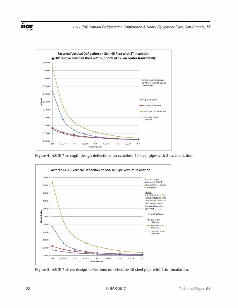
applicable loading is shown in Table 2, and Figures 1 and 2 illustrate graphically
how the loading varies with the size of the pipe. Figure 3 illustrates graphically
how ASCE 7 factored load combinations for the applicable vertical forces will vary
with the size of the pipe. Figures 4 and 5 illustrate potential pipe displacements for
applicable ASCE 7 strength design load combinations and allowable stress design
load combinations. The deflection illustrated is based on wind loads discussed in
this paper. Deflection from thermal expansion and contraction and hammer forces
for start-up and fatigue should also be considered when evaluating stresses on pipe
connections and joints.

18 © IIAR 2017 Technical Paper #4
2017 IIAR Natural Refrigeration Conference & Heavy Equipment Expo, San Antonio, TX
Table 1. Design criteria summary.

Technical Paper #4 © IIAR 2017 19
Code Requirements for the Evaluation and Design of Rooftop Equipment Supports
Table 2. Applicable rooftop equipment loading on schedule 40 steel pipe with 2 in. insulation.

20 © IIAR 2017 Technical Paper #4
2017 IIAR Natural Refrigeration Conference & Heavy Equipment Expo, San Antonio, TX
Figure 1. Design lateral loading on schedule 40 steel pipe with 2 in. insulation.
Figure 2. Design vertical loading on schedule 40 steel pipe with 2 in. insulation.

Technical Paper #4 © IIAR 2017 21
Code Requirements for the Evaluation and Design of Rooftop Equipment Supports
Figure 3. ASCE 7 factored vertical loading on schedule 40 steel pipe with 2 in. insulation.
22 © IIAR 2017 Technical Paper #4
2017 IIAR Natural Refrigeration Conference & Heavy Equipment Expo, San Antonio, TX
Figure 4. ASCE 7 strength design deflections on schedule 40 steel pipe with 2 in. insulation.
Figure 5. ASCE 7 stress design deflections on schedule 40 steel pipe with 2 in. insulation.

Technical Paper #4 © IIAR 2017 23
Code Requirements for the Evaluation and Design of Rooftop Equipment Supports
From these figures you can see how wind loading in both the lateral and uplift
direction will generally control the design of the support frames. Some conditions in
the seismic portion of the code will still need to be met where seismic evaluation is
required, but generally, the design to accommodate the wind loading requirements
will also meet or exceed the seismic design requirements.
Another factor that can significantly affect wind loading on a pipe is insulation
thickness. The added weight will not significantly affect gravity or seismic loading,
but going from 2 in. of insulation to 4 in. of insulation will nearly double the
applicable lateral and uplift wind loading on a piped system.
Application
Once the applicable loading to the pipe has been determined, the support frame
system can be designed accordingly. After applying the various load combinations,
the worst case or governing case for downward, uplift, and lateral loading will be
accounted for in the design of the support frame. Note also that frames supporting
multiple pipes will need to be evaluated with the applicable loading from each
pipe being transferred to the support frame. Due to the complexity of evaluating
the various load combinations with placement of loading at various locations and
magnitudes on a support using design software such as RISA 3D or other software
packages to design the support frames is common. The design software provides
an accelerated method to evaluate the support frames and make changes or
modifications where required to optimize the members used in the construction of
the frame and find the reactions from the frame that will need to be transferred to the
building structure.
The final design and installation of properly designed rooftop piping support frames
will require coordination among the building owner, the mechanical engineer, the
building structural engineer of record, the mechanical contractor, a roofer, and the

24 © IIAR 2017 Technical Paper #4
2017 IIAR Natural Refrigeration Conference & Heavy Equipment Expo, San Antonio, TX
support supplier. The support supplier will likely also be working with an engineer
who will be running the calculations for the support frames and providing the sealed
submittal package for the frames.
Summary
The ammonia refrigeration industry is by no means lacking in established design
procedures, regulations, and oversight, and justifiably so. The risk associated with
the failure of an ammonia distribution line or associated equipment can have serious
health and economic consequences. Code requirements and industry standards are
established and maintained with the primary goal of protecting the health, safety,
and general welfare of the community. The requirement to address wind and seismic
loading on rooftop equipment, which includes piping and other distribution lines and
their supports, is included in the International Code Council’s family of codes and
other adopted state/local codes and standards, industry standards, and insurance
standards. The codes and standards will evolve and adapt as more research is
conducted and through the involvement of those with a vested interest in how the
codes are written and interoperated.
Current codes are written in a manner that will generally require a site-specific design
of support frames to meet applicable loading requirements. Rooftop equipment
and supports exposed to wind shall be determined for each pipe or component
being supported per the requirements found in the International Building Code and
ASCE 7. Where earthquake loading is applicable, rooftop equipment and supports
shall be designed in accordance with the International Building Code and ASCE 7.
Other environmental loading considerations may also require evaluation based on
the requirements of the local building official. Coordination between trades and
professions is essential to ensure a properly designed and installed system that will
meet both code requirements and customer expectations. Early consideration and
coordination between trades in the design phase of a project can also ease financial
and project completion consequences.

Technical Paper #4 © IIAR 2017 25
Code Requirements for the Evaluation and Design of Rooftop Equipment Supports
References
Arindam Gan Chowdhury, PhD & Jimmy Erwin, Research Graduate Department of Civil
and Environmental Engineering Florida International University (2017), Rooftop Equipment
Wind Load and it’s Mitigation for Buildings in Hurricane Prone Regions, A Research Project
Funded by The State of Florida Divion of Emergency Management in partnership
with The International Hurricane Research Center Florida International University
ANSI/IIAR Standard 2 (2014), Standard for the Safe Design of Closed-Circuit
Ammonia Refrigeration Systems
Applied Technology Council (ATC), Wind Speed by Location,
Sponsored by the ATC Endowment Fund
Page URL: http://www.atcouncil.org,
Page Contact Information: http://windspeed.atcouncil.org/index.php/contact
Page Last Modified: Unknown
ASCE Standard ASCE/SEI 7-10 (2010), Minimum Design Loads for Buildings and
Other Structures, American Society of Civil Engineers
ASHRAE Standard 15 (2016), Safety Standard for Refrigeration Systems
Federal Emergency Management Agency (2006), Attachment of Rooftop Equipment in
High-Wind Regions, Hurricane Katrina Recovery Advisory, FEMA 549.
International Code Council (2014), 2015 International Building Code, International
Code Council
International Code Council (2014), 2015 International Mechanical Code, International
Code Council
U.S. Department of Interior, U.S. Geological Survey (USGS), U.S. Seismic Design Maps
Page URL: http://earthquake.usgs.gov/designmaps/us/application.php
Page Contact Information: https://answers.usgs.gov/cgi-bin/gsanswers

Notes:
26 © IIAR 2017 Technical Paper #4
2017 IIAR Natural Refrigeration Conference & Heavy Equipment Expo, San Antonio, TX