cogenie - szanyo.hu · hot water driven absorption chillers cogenie 10 ntr - 80 ... a helium leak...
TRANSCRIPT

F O R A I R C O N D I T I O N I N G A N D I N D U S T R I A L C O O L I N G
T h e e c o - f r i e n d l y s o l u t i o n . . . .
The Latest Advanced TechnologyHigh Efficiency Series
H O T W A T E R D R I V E N A B S O R P T I O N C H I L L E R S
Cogenie
10 NTR - 80 NTR
Cogenie theawardedEnvironmental Productof the Year 2001ACR News, U.K.
2
hot water driven absorption chillers
Conserving Energy and
Preserving the Environment.
At Thermax, not only are the
products eco-friendly, but also the
manufacturing processes. They
even conform to the Kyoto
Protocol and are in absolute
tandem with Clean Development
Mechanisms Code (CDM) which
is becoming the order of times
worldwide.
t ab l e o f conten t s
Introduction 3
Manufacturing and Testing 4
CHPC 5
Features 6-7
Controls 7
Technical Specifications and
GA Drawing
Cycle Diagram 12
Performance Curves 8
Safeties 8
Testing Procedure 8
Operating Principle 9
10
P & I Diagram and Foundation Drawing 11
Hotels Hospitals
Multiplexes
Auditoriums
Retail Stores
Office Complexes Schools
Residential Blocks Museums
Shopping Malls
Restaurants
Fast Food Parlours
Cogenie
A P P L I C A T I O N S
Cogenie theawardedEnvironmental Productof the Year 2001ACR News, U.K.
VA
PO
UR
ABSORPTIO
NC
HIL
LE
RS
CFC
FREE

a company with engineering excellence ...
Thermax, a technology driven company has been in the core sectors of
for more than 25 years and has
defined its business as -
Electricity is scarce and expensive. It should be used
only where it is irreplaceable. Keeping this in mind, Thermax took up
the challenge of finding an alternative for traditional electrically
operated compression chillers. About a decade ago, Thermax
introduced the revolutionary concept of
for air-conditioning and process cooling requirements, in India.
Considering the growing demand for Vapour Absorption Chillers,
Thermax set up its state-of-the-art manufacturing plant in 1988, in
India at Pune which has been awarded the ISO 9001 and the ISO 14001
certificates. Needless to mention, these chillers conform to
international standards. To maintain these high standards, a team of
workers and engineers is specially trained and exposed to global work
and quality culture. With this positive and innovative attitude, Thermax
has carved a niche in the global market where competition is stiff and
performance is the only criteria.
Thermax sales and after-sales service is efficient, responsive and
responsible. Our Engineers understand customer requirements, design
the most optimal solutions and ensure quality at every stage, to achieve
customer delight.
Energy, Environment and Exports
Conserving Energy and Preserving the
Environment.
Vapour Absorption Chillers
3

hot water driven absorption chillers
Thermax manufactures the environment friendly and
energy efficient Vapour Absorption Chillers at its plant
in Pune, India. Its state-of-the-art manufacturing facility
is awarded with ISO 9001 and ISO 14001 certificates.
Stringent quality control procedures alongwith a skilled
workforce ensure that a highly reliable product leaves
the factory. The equipment and manufacturing processes
conform to most of the International standards.
Thermax’s manufacturing capabilities are confirmed by
thefactthatovertheyearsit hasinstalledmanychillers in
countries like USA, Germany, UK, Spain, Italy, Middle
East, South East Asia with the product conforming to the
respective country standards like ETL, CE, TUV, DNV,
ISPESL, ASME, etc.
The chillers can be performance tested under the
simulated site conditions before it leaves the factory. The
factory assembled and tested unit considerably reduces
the time needed for installation and commissioning at
site.
CNC drilling machine with high speed and direct feed technology
ensures fine tube hole finish and accuracy, which is important for
leak tight expansion and effective heat transfer.
CNC Gas cutting machine for plate cutting ensures precision
cutting of shell plates and profile cut tube plates.
A Helium leak detection test ensures there is no leakage at
the welding joints.
M A N U F A C T U R I N G & T E S T I N G
4
Cogenie

100%
Coolant Losswithout heat recovery
24.5%
Radiation Loss3.3%
Hotwater
driven chiller
Stackloss afterheat recovery
13.6%
Stackloss withoutheat recovery
33.6%
Mechanicaloutput38.6%
Alternatorloss
3.6%
Steamgenerated
20%
Net useful outputpower + heat + chillingfrom steam driven chiller
55%
Electricaloutput35%
Sankey Diagram
GensetCapacity
6 MW
4 MW
2.5 MW
1.5 MW
225
150
100
70
Indicative ChillingCapacity (TR)
Indicative Table
Jacket water Inlet / OutletTemperature : 90.6 / 85 Co
hot water driven absorption chillersCogenie
Chilled Water
NaturalGas
Gas Turbine
Air
Air
Exhaust toAtmosphere
Alternator
Hot TurbineGases
After FiringBurner
Hot Water
To Cooling Tower
Hot Water
Electricity
HotWaterChiller
HeatRecoveryUnit
NaturalGas
Air
HeatRecoveredfrom Engine 85 C
o
85 Co
90.6 Co
90.6 Co
HotWater
6.7 Co
6.7 Co
29.4 Co
29.4 Co
To Cooling Tower
Chilled Water
Alternator
JacketWater
Electricity
12.2 Co
12.2 Co
HotWaterChiller
Gas Engine
M I C R O T U R B I N E C H PG A S E N G I N E C H PExhaust toAtmosphere
The concept of co-generation by means of Genset is becoming
increasingly popular worldwide for reducing overall energy
costs.
Sankey Diagram :
The Sankey diagram shows the heat energy distribution per unit
quantity of fuel to a Genset. The portion indicated in blue
represents the net useful output which is raised from 35% to 65%
by recovering the waste heat from exhaust gases and jacket water,
to enhance the utilization of fuel.
Around 25% of the input energy of the Genset is wasted in a
cooling tower to cool the jacket water coming out of the engine,
which is at a high temperature. The same heat can be used as an
energy heat source for the Hot water driven chiller to produce
chilling at a negligible cost.
The benefits of CHPC systems were confined to large scale
projects only. With the launch of Cogenie series (10 NTR - 80
NTR) Thermax is now extending these benefits to small scale
projects too! This reiterates Thermax's commitment to provide
the most economical and "Best in Class" solutions for Combined
Heat, Power and Cooling systems.
Cogenie can work on following CHPC schemes :
1. Gas Engine CHP
2. Microturbine CHP
The typical system schematic given below explains the
connectivity between the Genset and Cogenie.
CHPC with Cogenie :
C O M B I N E D H E A T , P O W E R & C O O L I N G S Y S T E M
5

f ea tures
Capacity :
Operating Hot Water Temperatures:
Compact Design :
High efficiency :
10-100% Stepless modulation :
Auto De-crystallization :
On-line purging :
Gravity feed system :
PLC based control panel :
Cogenie is available in models ranging from 10 NTR - 80 NTR and can achieve chilled water
temperature upto 4.5 C.
Cogenie can operate on Hot water temperatures ranging from : 70 C - 110 C
Cogenie are designed to be extremely compact. This ensures minimum foot print area and provides ease
of transportation and installation.
Special tube material and other innovations help to increase the COP considerably.
For cooling loads ranging from 10% to 100% of the designed capacity, a 3-way diverting valve
automatically varies hot water flow in order to maintain the temperature of chilled water leaving the
chiller. This ensures better part load performance.
These chillers are installed with a unique auto de-crystallization circuit to eliminate any chances of
crystallization.
The factory mounted and tested purging unit consists of an electric motor driven purge pump, palladium
cell, storage tank, necessary piping and valves. Any non-condensable gas generated in the chiller
during operation, is purged continuously into the storage tank, thereby maintaining low vacuum in the
shell. The gases stored in the tank can be purged periodically. Palladium cell purges Hydrogen from the
storage tank continuously thus reducing the requirement of running the purge pump.
The Thermax chillers use gravity feed, non-pressurized super-spraying system, for spraying refrigerant
and absorbent. This avoids the use of nozzles, which have the problem of clogging and wear & tear.
These chillers are provided with state-of-art PLC based control panel with unique display, user friendly
interface and data-logging system.
o
o o
hot water driven absorption chillers
hot water driven absorption chillers
Cogenie
Cogenie
6

Cross-over piping :
Generator Tubes:
Corrosion Inhibitors:
The cross-over piping from absorber to condenser is a standard feature in Thermax Absorption Chillers. It reduces the
piping work, welding, at site.
Cogenie uses Low fin Copper tubes in its generator for better performance.
Thermax uses new generation corrosion inhibitor, Lithium Molybdate which is more effective than conventionally
used Lithium Nitrate and Lithium Chromate. Lithium Nitrate can generate Ammonium Nitrate (NH NO ) which is
harmful to Copper.4 3
Electrical / Pneumatic Control Valve :
Factory Performance test :
As an option Cogenie can be provided with Electrical/ Pneumatic Control Valve.
After assembly, the chillers can be performance tested under simulated site conditions before it leaves the
factory. The factory assembled and tested units considerably reduce the time needed for installation and
commissioning at site.
hot water driven absorption chillers
Cogenie
CogenieP LC co ntro l s
op t ion a l f e a t u res
Improved Reliability :
Elaborate Diagnostics :
Easier Operation & Maintenance :
Data Acquisition and Logging :
Holiday Schedule :
Cogenie incorporates a state-of-the-art programmable logic controller, which
incredibly enhances the flexibility and reliability of the chiller. It brings along
all the advantages of a solid state control system. Elimination of rigid electro-
mechanical control components promises enhanced reliability and fail safe
operation, which reduces maintenance and ensures minimum downtime of the
chiller.
chiller
Control system allows the user to log parameters noted in the last one week, at
a sampling time of one hour. During a chiller trip condition, the data is logged
at a faster, adjustable sampling time. Also a log of last six alarms with date and
time stamp is maintained.
Client can program chiller operating schedule as per his convenience so that
the chiller is switched on or switched off as per the programmed schedule. It
can be set by the customer anytime.
Thermax Control system provides a host of diagnostic information such as
hardware related faults, chiller trip causes, sensor errors, pump errors and
data history regarding previously occurred faults and alarms. This equips the
operator with an overview of the chiller and adequate data for faster and easier
troubleshooting and routine maintenance.
Unique 2 line display, keypad and the software constitute a user-friendly
operator interface. The operator can easily control the functions, with
the aid of self-explanatory messages appropriately displayed on the screen.
The status screen provides audio-visual alarms and displays warnings about
the abnormal conditions in the chiller function. This alerts the operator,
specifying the abnormality, to initiate the necessary action.
7

CogenieT E S T I N G P R O C E D U R E
As the Vapour Absorption Chillers work under vacuum conditions, the manufacturing of these chillers is very critical with
respect to leak tightness. Hence it is necessary to follow stringent quality control procedures and also perform leak
detection tests. Understanding the importance, Thermax carries out the leak detection test in the following sequence :
Nitrogen is charged into the shell side of the chiller upto 1.3 to 1.4 kg/cm g pressure and soap solution is sprayed on all the
joints and expanded tube ends. In case of leakage, Nitrogen leaks out, forming soap bubbles, indicating the leak points.
The chiller is kept under pressurized condition for 24 hours, by charging it with Nitrogen upto 1.3 kg/cm g pressure on the
shell side. In case of leakage, Nitrogen escapes out, resulting in drop in Nitrogen pressure inside the chiller, indicating
leakage.
Helium, the next smallest molecule after Hydrogen, can leak through very minute holes. In this test Helium is sprayed on
all the joints of the chiller. As the chiller is under vacuum conditions, leakages, if any, will result in Helium entering into the
chiller and thus will be displayed on the screen of Helium leak detector. The joints are marked for repairs.
In this test, the chiller is fully covered by a polythene sheet and Helium is passed from below, to observe the cumulative
leak rate of the entire chiller.
After the chiller passes all the above tests, it is tested for hydraulic test, at 1.5 times the design pressure on the tube side.
2
2
1. Nitrogen or Soap Test :
2. Decay Test :
3. Helium Spray Test :
4. Helium Shroud Test :
5. Hydraulic Test :
CH/W : Chilled Water
C/W : Cooling Water
H/W : Hot Water* Above graphs are for indicative purpose only.
CAPACITY V/S C/W INLET TEMPERATURE
At constant CH/W & H/W inlet / outlet temperatures,& C/W flow
COOLING WATER INLET TEMPERATURE ( C)o
CAPACITY
%28 29 30 31 32
120
110
100
90
80
70
CAPACITY V/S H/W INLET TEMPERATURE
At constant CH/W temperatures,C/W inlet temperature & flows
HOT WATER INLET TEMPERATURE ( C)o
CAPACITY
% 90.6 89.6 88.6 87.6 86.6 85.6
100
90
80
70
P E R F O R M A N C E C U R V E S
L-cut - refrigerant pump
Antifreeze thermostat
Chilled water pump interlock
Chilled water flow switch
Generator temperature high cutout
Cooling water low temperature cutout
Antifreeze Protection :
Crystallization Protection :
Alarm Cycle :
Motor Protection :
Chiller routine fault alarm
Total shutdown alarm
Absorbent pump overload relay
Refrigerant pump overload relay
Purge pump overload relay
S A F E T I E S Cogenie
8
29.4

Absorption process
Cooling water
LiBr solutionConcentrated
Water (refrigerant) Closed vessel
Vacuum
Chilled water
Water circulatingheat exchangertubes
ConcentratedLiBr solution
Water (refrigerant)
Refrigerant vapour
Driving heat source
Diluted solution
Absorption pump
Chilled water
Absorber
Cooling water
Concentratedsolution
Liquidrefrigerant
Refrigerant vapour
GeneratorCondenser
Absorbent Pump
Driving heatsource
Coolingwater
Coolingwater
AbsorbentPump
Chilled water
CONDENSER GENERATOR
EVAPORATOR ABSORBER
5
O P E R A T I N G P R I N C I P L E
Vapourized refrigerant
Refrigerant
Chilled water
Chilled water
Evaporator
4
1
2
3
Drivingheatsource
When maintained at high vacuum, water will boil and flashcool itself.
Concentrated Lithium Bromide solution has affinity towardswater. The solution absorbs vapourised refrigerant water.
As Lithium Bromide becomes dilute it loses its capacity to absorbwater vapour. It thus needs to be reconcentrated using a heat source.
The basic operation cycle of the single effect vapour absorption
chiller.
This heat causes the solution to release the absorbed refrigerant in the form ofvapour. This vapour is cooled in a separate chamber to become liquid refrigerant.
hot water driven absorption chillersCogenie
Opera t ing Pr inc iple :
The vapour absorption chiller produces chilled water upto
C, utilizing hot water as the driving source. The
chiller utilizes the latent heat absorbed by the refrigerant
(water) as it evaporates (in a closed pressure vessel,) for
cooling. Unlike a compression chiller which uses a
compressor to pressurize the vapourized refrigerant
(Freon) and condenses it by using cooling water, the
absorption chiller uses an absorbent (LiBr) to absorb the
vapourized refrigerant (water). The refrigerant is then
released from the absorbent when heated by an external
source.
4.5o
Basic Pr inc iple :
Boiling point of water is a function of pressure. At
atmospheric pressure, water boils at 100 C. At lower
pressure it boils at lower temperature. The boiling point of
water at 6 mm of mercury absolute, is only 3.7 C.
o
o
Lithium Bromide (LiBr) salt has the property to absorb
water due to its chemical affinity. It is soluble in water. As
the concentration of LiBr increases, its affinity towards
water increases. Also as the temperature of LiBr increases
the affinity decreases.
There is a large difference between vapour pressure of
LiBr and water.
9

UNIT LT - 1 LT - 2 LT - 3 LT - 5 LT - 6 LT - 8
NTR 10 20 30 50 65 80
Length (L) mm 1600 1800 2300 2400 2500
Width (W) mm 1600 1400 1400 1500 1800
Height (H) mm 2100 2200 2100 2500 2800
Operating weight x 10 kg 2 2.5 3 4 5.5 5.8
Maximum Shipping weight x 10 kg 1.75 2.2 2.5 3.5 4.2 4.5
Clearance for tube removal mm 1500 2200
3
3
MODEL NUMBERS
NOMINAL REFRIGERATION CAPACITY
DIMENSIONS
T E C H N I C A L S P E C I F I C A T I O N S
T Y P I C A L G E N E R A L A R R A N G E M E N T
EARTH TERMINAL / ELECTRICAL WIRING OPENING
ACCESS DOOR FOR CONTROL PANEL
DESCRIPTION
B
MAINTENANCE SPACE (DOOR SPACE)
ANCHOR BOLT LOCATION
TUBE CLEANING SPACE
H
G
F
C
DIRECT SPACE
SR.
A
LEGEND :NOZZLE SCHEDULE
HOT WATER OUTLET
COOLING WATER INLET
N6
N5
N3
N4
N1
N2
SR. DESCRIPTION
CHILLED WATER INLET
CHILLED WATER OUTLET
COOLING WATER OUTLET
HOT WATER INLET
10
Minimum operating cooling water inlet temperature = 20°CMinimum chilled water outlet temperature = 4.5°C
Fouling Factor in water circuits is 0.0001 metricMaximum working pressure in chilled / cooling / hot water lines = 5 kg/cm gVoltage available on request : 380 / 440 / 460 V, 50 / 60 Hz
Ambient condition should be between 5 to 45°C
Performance based on JIS B8622
2
FOR CONDITIONS OTHER THAN ABOVE
PLEASE CONTACT THE NEAREST
THERMAX OFFICE / DISTRIBUTOR
CHILLED WATER
CIRCUIT
HOT WATER
COOLING WATER
CIRCUIT
CIRCUIT
ELECTRICAL
DATA
MODEL NUMBERS
NOMINAL REFRIGERATION CAPACITY
UNIT LT - 1 LT - 2 LT - 3 LT - 5 LT - 6 LT - 8
NTR 10 20 30 50 65 80
kW 35 70 106 176 229 282
Flow Rate m /hr 5.5 11 16.5 27.5 35.7 44
Friction Loss m.w.c. 6.8 5.9 3.2 4.4 3.2 4.1
Connection Diameter mmNB 40 65 80 100
Flow Rate m /hr 10 20 30 50 67 85
Inlet Temperature
Friction Loss m.w.c. 1.2 3.0 4.0 4.1 5.1 5.5
Connection Diameter mmNB 50 80 125
Flow Rate m /hr 7.8 15.7 23.2 39.8 51.3 63.1
Friction Loss m.w.c. 1.2 2.0 3.2 3.2 3.1 3.0
Connection Diameter mmNB 40 65 80 100
Absorbent Pump kW (A) 0.3 (1.1) 0.55 (1.7) 1.5 (5.0)
Refrigerant Pump kW (A) 0.3 (1.1) 0.3 (1.4)
Purge Pump kW (A) 0.25 (1.3)
Total power consumption kVA 2.2 2.83 5.2
3
3
3
Inlet / Outlet Temperature °C 12.2 / 6.7
No of passes (Evaporator) nos. 8 4
°C 29.4
Outlet Temperature °C 36.8 36.7 36.6 36.7 36.4 36.3
No of passes (Absorber) nos. 4
No of passes (Condenser) .nos. 2
Inlet / Outlet Temperature °C 90.6 / 85
No of passes (Generator) nos. 4
Power Supply 415 V(± 10%), 50 Hz( ± 5%), 3 Phase+N
TS
TUBE CLEANING SPACE
ON ANY ONE SIDE
A
ON
AN
YO
NE
SID
E
TU
BE
CLE
AN
ING
SP
AC
E
C
F
G
B
N2
N1
N6
N3
N5
N4
L
46
W
H
H
Cogenie
F O R R E F E R E N C E O N LY

11
T Y P I C A L S Y S T E M P & I D I A G R A Mhot water driven absorption chillers
HOT WATER OUTLET
HOT WATER INLET
E/P
AIR HEADER
CH
ILLE
DW
AT
ER
INLE
T
(1 WORKING + 1 STD. BY)
CHILLED WATER PUMPS
INSULATION
THERMOCOL
2" THICK.
CHILLED WATER OUTLET
2" THICK
THERMOCOL
INSULATION
COOLING WATER OUTLET
CO
OLI
NG
WA
TE
RIN
LET
COOLING WATER PUMPS
(1 WORKING + 1 STD. BY)
DOWN
COOLING TOWER
BLOW
REFER NOTE-1
S
AIR
SU
PP
LYF
RO
M
CO
MM
ON
HE
AD
ER
.
PIPI
M
M
PIPI
PI TI
PI TI
PI
PI TIPI TI
PI TI
PI TI
TI
PI
M
PI
PI
M
PI
FM
CONTROL VALVE
PNEUMATIC CONVERTERE/P
THERMOSTAT
BALANCE VALVE
MOTOR
PUMP
GLOBE VALVE (CLOSE)
GATE VALVE (CLOSE)
BUTTERFLY VALVE (CLOSE)
PNEUMATIC LINE
THERMODYNAMIC STEAM TRAP
INVERTED BUCKET STEAM TRAP
S - SWITCH
R - RECORDER
L - LOW
I - INDICATOR
M - METER
F - FLOW
L - LEVEL
T - TEMPERATURE
P - PRESSURE
BUTTERFLY VALVE (OPEN)
AIR FILTER REGULATOR
COCK
``Y'' STRAINER
NON RETURN VALVE
GLOBE VALVE (OPEN)
GATE VALVE (OPEN)
M
F O R R E F E R E N C E O N LY
1. AUTOMATIC ARRANGEMENTS SHOULD BE PROVIDED TO STOP
COOLING WATER FLOW IF THE CHILLED WATER FLOW STOPS.
NOTES:
2. THERMAX SCOPE IS UP TO THE NOZZLES OF ALL WATER CIRCUITS
Cogenie
Cogenie
NOTES :
1. There should be a drain ditch around the foundation.
2. Anchor bolts should be fixed in the foundation prior to the chiller installation.
3. Anchor bolts (anchor bolts, nuts & washers) are supplied with the chiller.
4. Be sure to weld the washer as shown in above detail.
5. The floor surface should be made water proof, for ease of maintenance work
F O U N D A T I O N D R A W I N G
A
F
DB
E
J
M
G
K
C
ON
AN
YO
NE
TU
BE
CLE
AN
ING
SP
AC
ES
IDE
G
UNIT mm
MODEL A B C D E F G J K M
LT-1 1250 1140 1100 635 1125 3450 850 275 1050 600
1250 1140 1100 635 1125 3450 850 275 1050 600
1872 940 1120 620 1220 4112 626 210 1120 680
1982 1047 1126 621 1300 4235 695 250 1350 700
2170 1341 1100 600 1282 4364 880 280 1398 969
2170 1295 1100 600 1282 4364 880 278 1398 969
LT-2
LT-3
LT-5
LT-6
LT-8
In view of our constant endeavour to improve the quality of products,we reserve the rights to alter or change design specifications and contents ofthis literature without prior notice and without incurring any obligations.
Visit us at : www.thermaxindia.com/acd
Distributor / Agent
THERMAX LTD.ABSORPTION COOLING DIVISION
ACD/Cogenie/08/01
Thermax world-wide network
REGISTERED OFFICE / WORKSD-13 MIDC Industrial Area,Chinchwad, Pune 411 019. INDIATel : 00-91-20- 7475941-49 / 7470436Fax : 00-91-20- 7475907
Thermax Inc.
Thermax Europe Ltd. :
U.K.
Thermax Rus Ltd. :Russia
Thermax Ltd. :Saudi Arabia
Thermax Ltd. :Kenya
Thermax Ltd. :
Nigeria
Thermax Ltd. :
Thermax Ltd. :
Indonesia
Thermax Ltd. :Bangladesh
Thermax Ltd. :Sri Lanka
40440 Grand River Avenue, Novi Michigan 48375, U.S.A.Tel : 00-1-248-426 0428 / 474 3050 Fax : 00-1-248-474 5790Email : [email protected]
Suite 7A, Britannia House, Leagrave Road, Luton, Bedfordshire,LU3 1RJ,Tel : 00-44-1582-727756 Fax : 00-44-1582-731538Email : [email protected]
Ulitsa Vavilova, House 69/75, Office 915, Moscow 117846,Tel : 00-7095-9350490-92 Fax : 00-7095-1347410Email : [email protected]
C/o. CIDC - Masdar, PO Box 20753, Al Khobar 31952,Tel : 00-966-3-891 9897 / 9594 / Fax No : 00-966-3-8914388 / 8911656Email : [email protected]
C/o. Spenomatic Kenya Ltd.,Post Box 39935, Nairobi,Tel : 00-254-2-803122/860264 / Fax : 00-254-2-444360Email : [email protected]
C/o. Multichem Industries Ltd., Plot D2, Israel Adebajo Close,Off Ladipo Oluwole Avenue, PO Box 5671, Ikeja, Lagos,Tel : 00-234-1-4924019 / 4936162 / Fax No : 00-234-1-4923998 / 2693746Email : [email protected]
Block B-22/3, Menara Bangsar, Jalan Maarof,
PT Comexindo Persada, Bidakara Bldg. 6 floor,Jl. Jendral Gatot Subroto KAV 71-73, Pancoran, Jakarta 12870,
35, New Eskaton Road, Sufia House, Dhaka,
C/o. Lalan Engg. Ltd. 344, Grandpass Road, Colombo-14,
Thermax Ltd. : U.A.E.
Malaysia
PO Box 17156 Jebel Ali, Dubai,Tel : 00-971-4-8816481 Fax : 00-971-4-8816039Email : [email protected]
Bukit Bandaraya, 59100 Kuala Lumpur,Tel : 00-60-3-2534775 Fax : 00-60-3-2544775Email : [email protected]
Tel : 00-62-21-83793259 / Fax : 00-62-21-83793258Email : [email protected]
Tel : 011-808001, 011-867393 / Fax No : 00-880-2-832963Email : [email protected]
Tel : 00-941-325997 /329566 / Fax No : 00-941-447060Email : [email protected]
th
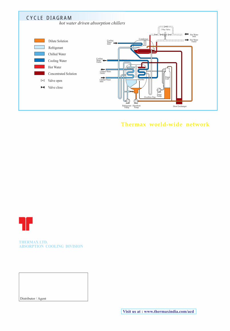
C Y C L E D I A G R A Mhot water driven absorption chillers
Heat Exchanger
Valve open
Valve close
Refrigerant
Dilute Solution
Chilled Water
Hot Water
Concentrated Solution
Cooling Water
Chilled WaterOutlet
CoolingWaterOutlet
CoolingWaterInlet
Chilled WaterInlet
Absorber
Hot WaterInlet
3 Way Valve
Hot WaterOutlet
PurgePump
PurgeUnit
RefrigerantPump
AbsorbentPump
Condenser
Overflow Pipe