cognition v2 hubs - sram
TRANSCRIPT

service manual
GEN.0000000006450 Rev A © 2021 SRAM, LLC
Cognition V2 Hubs

SRAM® LLC WARRANTYTHIS WARRANTY GIVES YOU SPECIFIC LEGAL RIGHTS AGAINST SRAM, LLC. YOU MAY ALSO HAVE OTHER RIGHTS THAT VARY FROM STATE TO STATE, COUNTRY, OR PROVINCE. THIS WARRANTY DOES NOT AFFECT YOUR STATUTORY RIGHTS. TO THE EXTENT THIS WARRANTY IS INCONSISTENT WITH THE LOCAL LAW, THIS WARRANTY SHALL BE DEEMED MODIFIED TO BE CONSISTENT WITH SUCH LAW. FOR A FULL UNDERSTANDING OF YOUR RIGHTS, CONSULT THE LAWS OF YOUR COUNTRY, PROVINCE, OR STATE.EXTENT OF LIMITED WARRANTYExcept as otherwise set forth herein, SRAM warrants its bicycle components to be free from defects in materials or workmanship for a period of two (2) years after original purchase of the product.
SRAM warrants all Zipp MOTO Wheels and Rims to be free from defects in materials or workmanship for the lifetime of the product.
SRAM warrants all non-electronic Zipp branded bicycle components, Model Year 2021 or newer, to be free from defects in materials or workmanship for the lifetime of the product.
GENERAL PROVISIONSThis warranty only applies to the original owner and is not transferable. Claims under this warranty must be made through the retailer where the bicycle or the SRAM product was purchased or a SRAM authorized service location. Original proof of purchase is required. All SRAM warranty claims will be evaluated by a SRAM authorized service location whereupon acceptance of the claim the product will be repaired, replaced, or refunded at SRAM's discretion. To the extent allowed by local law claims under this warranty must be made during the warranty period and within one (1) year following the date on which any such claim arises.
NO OTHER WARRANTIESEXCEPT AS DESCRIBED HEREIN, AND TO THE EXTENT ALLOWED BY LOCAL LAW, SRAM MAKES NO OTHER WARRANTIES, GUARANTIES, OR REPRESENTATIONS OF ANY TYPE (EXPRESS OR IMPLIED), AND ALL WARRANTIES (INCLUDING ANY IMPLIED WARRANTIES OF REASONABLE CARE, MERCHANTABILITY, OR FITNESS FOR A PARTICULAR PURPOSE) ARE HEREBY DISCLAIMED.
LIMITATIONS OF LIABILITYEXCEPT AS DESCRIBED HEREIN, AND TO THE EXTENT PERMITTED BY LAW, IN NO EVENT SHALL SRAM OR ITS THIRD PARTY SUPPLIERS BE LIABLE FOR DIRECT, INDIRECT, SPECIAL, INCIDENTAL, OR CONSEQUENTIAL DAMAGES. SOME STATES (COUNTRIES AND PROVINCES) DO NOT ALLOW THE EXCLUSION OR LIMITATION OF INCIDENTAL DAMAGES, SO THE ABOVE LIMITATION MAY NOT APPLY TO YOU.
LIMITATIONS OF WARRANTYThis warranty does not apply to products that have been incorrectly installed, adjusted, and/or maintained according to the respective SRAM user manual. The SRAM user manuals can be found online at sram.com/service.
This warranty does not apply to damage to the product caused by a crash, impact, abuse of the product, non-compliance with manufacturer's specifications of intended usage, or any other circumstances in which the product has been subjected to forces or loads beyond its design.
This warranty does not apply when the product has been modified, including but not limited to, any attempt to open or repair any electronic and electronic related components, including the motor, controller, battery packs, wiring harnesses, switches, and chargers.
This warranty does not apply when the serial number or production code has been deliberately altered, defaced, or removed.
SRAM components are designed for use only on bicycles that are pedal powered or pedal assisted (e-Bike/Pedelec).
Notwithstanding anything else set forth herein, the battery pack and charger warranty does not include damage from power surges, use of improper charger, improper maintenance, or such other misuse.
This warranty shall not cover damages caused by the use of parts of different manufacturers or parts that are not compatible or suitable for use with SRAM components.
This warranty shall not cover damages resulting from commercial (rental) use.
WEAR AND TEARThis warranty does not apply to normal wear and tear. Wear and tear parts are subject to damage as a result of normal use, failure to service according to SRAM recommendations, and/or riding or installation in conditions or applications other than recommended.
WEAR AND TEAR PARTS INCLUDE:• Aero bar pads• Air sealing o-rings• Batteries• Bearings• Bottomout pads• Brake pads• Bushings• Cassettes
• Chains• Corrosion• Disc brake rotors• Dust seals• Free hubs, Driver bodies, Pawls• Foam rings, Glide rings• Handlebar grips• Jockey wheels
• Rear shock mounting hardware and main seals
• Rubber moving parts• Shifter and Brake cables
(inner and outer)• Shifter grips• Spokes• Sprockets
• Stripped threads/bolts (aluminum, titanium, magnesium or steel)
• Tires• Tools• Transmission gears• Upper tubes (stanchions)• Wheel braking surfaces
ZIPP IMPACT REPLACEMENT POLICYZipp branded products, Model Year 2021 or newer, are covered under a lifetime impact-damage replacement policy. This policy can be used to obtain a replacement of a product in the event of non-warranty impact damage occurring while riding your bicycle. See www.zipp.com/support for more information.

SAFETY FIRST!We care about YOU. Please, always wear your safety glasses
and protective gloves when servicing Zipp® products. Protect yourself! Wear your safety gear!

TABLE OF CONTENTSZIPP SERVICE .......................................................................................................................................................................................................8
PART PREPARATION ......................................................................................................................................................................................................................................8SERVICE PROCEDURES .................................................................................................................................................................................................................................8
REAR HUB SERVICE ............................................................................................................................................................................................9PARTS, TOOLS, AND SUPPLIES ..................................................................................................................................................................................................................9REAR HUB EXPLODED VIEW ..................................................................................................................................................................................................................... 10REAR HUB DISASSEMBLY ............................................................................................................................................................................................................................ 11REAR HUB CLUTCH REMOVAL ................................................................................................................................................................................................................. 14REAR HUB BEARING INSTALLATION ...................................................................................................................................................................................................... 17REAR HUB CLUTCH INSTALLATION ........................................................................................................................................................................................................ 19DRIVER BODY INSTALLATION ................................................................................................................................................................................................................... 21REAR HUB END CAP INSTALLATION ..................................................................................................................................................................................................... 22DRIVER BEARING REPLACEMENT (OPTIONAL) ................................................................................................................................................................................. 23
FRONT HUB SERVICE ...................................................................................................................................................................................... 25TOOLS AND SUPPLIES NEEDED FOR SERVICE ................................................................................................................................................................................. 25FRONT DISC BRAKE HUB EXPLODED VIEW ....................................................................................................................................................................................... 26FRONT RIM BRAKE HUB EXPLODED VIEW .......................................................................................................................................................................................... 26FRONT HUB DISASSEMBLY ...................................................................................................................................................................................................................... 27FRONT HUB BEARING INSTALLATION ..................................................................................................................................................................................................30FRONT HUB AXLE AND END CAP INSTALLATION ............................................................................................................................................................................ 32

5Zipp Service
Z i p p S e r v i c eWe recommend that you have your Zipp compononets serviced by a qualified bicycle mechanic. Servicing Zipp compononets requires the use of specialized tools. Failure to follow the procedures outlined in this service manual may cause damage to your component and void the warranty.
Visit www.zipp.com/support for the latest Zipp Spare Parts catalog and technical information. For order information, please contact your local Zipp distributor or dealer.
Information contained in this publication is subject to change at any time without prior notice.
Your product's appearance may differ from the pictures contained in this publication.
For recycling and environmental compliance information, please visit: https://www.sram.com/en/company/about/environmental-policy-and-recycling.
P a r t P r e p a r a t i o n Remove the component from the bicycle before service.
Disconnect and remove the remote cable or hydraulic hose from the fork or rear shock, if applicable. For additional information about RockShox remotes, user manuals are available at www.sram.com/service.
Clean the exterior of the product with mild soap and water to avoid contamination of internal sealing part surfaces.
S e r v i c e P r o c e d u r e sThe following procedures should be performed throughout service, unless otherwise specified.
Clean the part with isopropyl alcohol and a clean, lint-free shop towel. Clean the part with isopropyl alcohol and a clean, lint-free shop towel.
NOTICETo prevent damage to the hub surfaces, do not use Acetone or similar products to clean parts.

6Rear Hub Service
R e a r H u b S e r v i c eThe hub can be serviced while in the wheel. However, if your spokes or rim are damaged, you can remove the hub from the wheel which will make servicing your hub easier. To remove the hub, use a spoke wrench to de-tension the spokes, then use a pair of metal snips to cut the spokes, remove the hub from the wheel, and remove the spoke ends from the hub (not pictured).
P a r t s , T o o l s , a n d S u p p l i e sParts
• Zipp Cognition 6903/61903 hub bearing (x2)
• Zipp Cognition driver (optional)
• Zipp Cognition 6803/61803 driver bearing (x2) (optional)
Safety and Protection Supplies
• Apron
• Clean, lint-free shop towels
• Nitrile gloves
• Safety glasses
Lubricants and Fluids
• Isopropyl alcohol
• Zipp Cognition or Klüber Staburags NBU30 grease
• Zipp Cognition Oil or Phil Bio-Lube and small oil syringe
Zipp/SRAM Tools
• Zipp 61903 Bearing Press Tool (x2) or Zipp 61903 Bearing Press Tool (x1) and SRAM 6903 Bearing Press Tool (x1)
Bicycle Tools
• Axle and spindle vise inserts - Park Tool AV-4 or AV-5
• Slide hammer bearing puller set
• 17 mm slotted attachment
• Wheels Manufacturing Press-1 Sealed Bearing Press Kit or similar
• 6903 30x17 bearing press adapters (x2)
• 6803 26x17 bearing press adapters (x2) (optional)
• 6002 32x15 bearing press adapter (optional)
• T-handle threaded bearing press
Common Tools
• Bench vise
• 3 mm hex wrench
• Grease brush
• Pick
• Rubber or plastic mallet
• Vise soft jaws (aluminum)
SAFETY INSTRUCTIONSAlways wear nitrile gloves when working with bicycle lubricants.

7Rear Hub Exploded View
R e a r H u b E x p l o d e d V i e w
R e a r H u b E n d C a p s
DRIVE SIDE NON DRIVE SIDE
Hub VariantsCurrent
Identification Text On End Cap
Previous Identification
Text On End Cap
Spare Part Kit Number
Current Identification
Text On End Cap
Previous Identification
Text On End Cap
Spare Part Kit Number
Cognition V2 REAR
QR RIM
11SPD127-000 10x(130/135) DS XD(R) 11.2018.065.008
178-000 10x130 NDS11.2018.065.008
XDR
CAMPA 161-000 10x135 DS C 11.2018.033.003 11.2018.033.001
12 x 142 CL
11SPD151-030 12x(142/148) DS XD(R) 11.2018.065.007
154-010 12x142 NDS CL11.2018.065.007
XDR
CAMPA 151-050 12x142 DS C 11.2018.049.040 11.2018.049.040
Disc Brake Hub Shell
Rim Brake Hub Shell
Clutch Seal Cap with integrated seal
Axle wave spring
Zipp Cognition 6903/61903 hub bearing
Zipp Cognition 6903/61903 hub bearing
Spring assembly
Hub Shell ratchet
Driver ratchet
Axle
Driver Body SRAM 10/11 Speed
Driver Body SRAM XDR
Driver Body Campagnolo 10-12 Speed
8Rear Hub Disassembly
R e a r H u b D i s a s s e m b l y
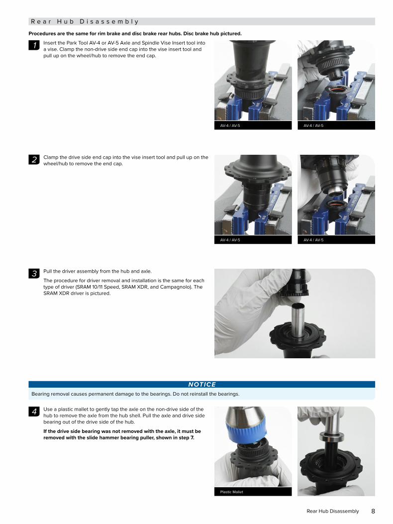
Procedures are the same for rim brake and disc brake rear hubs. Disc brake hub pictured.
Insert the Park Tool AV-4 or AV-5 Axle and Spindle Vise Insert tool into Insert the Park Tool AV-4 or AV-5 Axle and Spindle Vise Insert tool into a vise. Clamp the non-drive side end cap into the vise insert tool and a vise. Clamp the non-drive side end cap into the vise insert tool and pull up on the wheel/hub to remove the end cap.pull up on the wheel/hub to remove the end cap.
Clamp the drive side end cap into the vise insert tool and pull up on the Clamp the drive side end cap into the vise insert tool and pull up on the wheel/hub to remove the end cap.wheel/hub to remove the end cap.
Pull the driver assembly from the hub and axle. Pull the driver assembly from the hub and axle.
The procedure for driver removal and installation is the same for each The procedure for driver removal and installation is the same for each type of driver (SRAM 10/11 Speed, SRAM XDR, and Campagnolo). The type of driver (SRAM 10/11 Speed, SRAM XDR, and Campagnolo). The SRAM XDR driver is pictured.SRAM XDR driver is pictured.
NOTICEBearing removal causes permanent damage to the bearings. Do not reinstall the bearings.
Use a plastic mallet to gently tap the axle on the non-drive side of the Use a plastic mallet to gently tap the axle on the non-drive side of the hub to remove the axle from the hub shell. Pull the axle and drive side hub to remove the axle from the hub shell. Pull the axle and drive side bearing out of the drive side of the hub.bearing out of the drive side of the hub.
If the drive side bearing was not removed with the axle, it must be If the drive side bearing was not removed with the axle, it must be removed with the slide hammer bearing puller, shown in step 7.removed with the slide hammer bearing puller, shown in step 7.
1
AV-4 / AV-5 AV-4 / AV-5
2
AV-4 / AV-5 AV-4 / AV-5
3
4
Plastic Mallet

9Rear Hub Disassembly
The wave spring on the non-drive side end of the axle will be The wave spring on the non-drive side end of the axle will be dislodged when the axle is removed. Remove the wave spring from the dislodged when the axle is removed. Remove the wave spring from the non-drive side hub shell.non-drive side hub shell.
Place the axle in between flat aluminum vise soft jaws, drive side Place the axle in between flat aluminum vise soft jaws, drive side down, with the bearing resting on top of the soft jaws. Make sure the down, with the bearing resting on top of the soft jaws. Make sure the axle bearing step does not contact the soft jaws. Use a plastic mallet axle bearing step does not contact the soft jaws. Use a plastic mallet to gently tap on the top of the non-drive end of the axle until it is to gently tap on the top of the non-drive end of the axle until it is dislodged from the bearing. Discard the bearing.dislodged from the bearing. Discard the bearing.
Spray isopropyl alcohol onto the axle and clean the axle with a shop Spray isopropyl alcohol onto the axle and clean the axle with a shop towel.towel.
NOTICETo avoid damage to the axle, do not allow the axle to contact the vise soft jaws. If the axle bearing step is damaged, the axle must be replaced.
If the drive side bearing was not removed with the axle, remove the If the drive side bearing was not removed with the axle, remove the drive side bearing from hub shell with a slide hammer bearing puller.drive side bearing from hub shell with a slide hammer bearing puller.
Insert the 17 mm slotted bearing puller attachment through the drive Insert the 17 mm slotted bearing puller attachment through the drive side bearing. Align the slotted attachment with the bottom of the side bearing. Align the slotted attachment with the bottom of the bearing, then tighten the slotted attachment to expand the puller inside bearing, then tighten the slotted attachment to expand the puller inside the bearing.the bearing.
NOTICEDo not overtighten the slotted attachment. For more detailed assembly and usage information, consult your bearing puller manufacturer's instructions.
5
6
Plastic Mallet
7
17 mm Slotted Bearing Puller

10Rear Hub Disassembly
Thread the shaft of the bearing puller into the slotted attachment. While Thread the shaft of the bearing puller into the slotted attachment. While holding the hub securely, forcefully pull back on the slide hammer to holding the hub securely, forcefully pull back on the slide hammer to remove the bearing from the drive side of the hub shell.remove the bearing from the drive side of the hub shell.
Remove the bearing from the slotted attachment.Remove the bearing from the slotted attachment.
Discard the bearing.Discard the bearing.
Insert the 17 mm slotted bearing puller attachment through the Insert the 17 mm slotted bearing puller attachment through the non-drive side bearing. Align the slotted attachment with the bottom of non-drive side bearing. Align the slotted attachment with the bottom of the bearing, then tighten the slotted attachment to expand the puller the bearing, then tighten the slotted attachment to expand the puller inside the bearing.inside the bearing.
NOTICEDo not overtighten the slotted attachment. For more detailed assembly and usage information, consult your bearing puller manufacturer's instructions.
Thread the shaft of the bearing puller into the slotted attachment. While Thread the shaft of the bearing puller into the slotted attachment. While holding the hub securely, forcefully pull back on the slide hammer to holding the hub securely, forcefully pull back on the slide hammer to remove the bearing from the non-drive side of the hub shell.remove the bearing from the non-drive side of the hub shell.
Remove the bearing from the slotted attachment and discard the Remove the bearing from the slotted attachment and discard the bearing.bearing.
8
Slide Hammer Bearing Puller
9
17 mm Slotted Bearing Puller
10
Slide Hammer Bearing Puller

11Rear Hub Clutch Removal
R e a r H u b C l u t c h R e m o v a l
Use a 3 mm hex wrench to gently pry the clutch seal cap free from the Use a 3 mm hex wrench to gently pry the clutch seal cap free from the hub shell. Use your fingers to remove the clutch seal cap.hub shell. Use your fingers to remove the clutch seal cap.
NOTICEDo not damage the clutch seal cap during removal. If the clutch seal cap is damaged it must be replaced.
Use your fingers to remove the o-ring. Spray isopropyl alcohol onto the Use your fingers to remove the o-ring. Spray isopropyl alcohol onto the clutch seal cap and o-ring and wipe them with a shop towel. Install the clutch seal cap and o-ring and wipe them with a shop towel. Install the o-ring back onto the clutch seal cap.o-ring back onto the clutch seal cap.
Push down on one side of the clutch assembly from the hub shell to Push down on one side of the clutch assembly from the hub shell to raise the opposite side. Use your fingers to remove the driver ratchet raise the opposite side. Use your fingers to remove the driver ratchet from the hub shell.from the hub shell.
Use a pick to lift one side of the hub shell clutch from the hub shell and Use a pick to lift one side of the hub shell clutch from the hub shell and remove it.remove it.
1
3 mm Hex
2
3
Pick

12Rear Hub Clutch Removal
Use a pick to remove the spring assembly from the hub shell.Use a pick to remove the spring assembly from the hub shell.
NOTICEDo not disassemble the plastic retainer.
If the spring becomes disloged from the plastic retainer, gently push the spring back into place and make sure the plastic snaps are connected.
NOTICETo prevent damage to the hub surfaces, decals, and foam spring, do not use Acetone or similar products to clean parts.
Press the spring assembly between two shop towels to remove old Press the spring assembly between two shop towels to remove old Cognition oil from the foam ring.Cognition oil from the foam ring.
NOTICEDo not apply any type of cleaning product to the foam ring.
Clean the hub shell ratchet and the driver ratchet with isopropyl alcohol Clean the hub shell ratchet and the driver ratchet with isopropyl alcohol and a clean shop towel.and a clean shop towel.
4
Pick
5
Shop Towel
6
Isopropyl Alcohol Shop Towel

13Rear Hub Clutch Removal
Spray isopropyl alcohol in the rear hub bearing bores and clean the Spray isopropyl alcohol in the rear hub bearing bores and clean the hub with a shop towel.hub with a shop towel.7
Isopropyl Alcohol
14Rear Hub Bearing Installation
R e a r H u b B e a r i n g I n s t a l l a t i o n
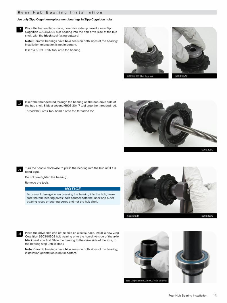
Use only Zipp Cognition replacement bearings in Zipp Cognition hubs.
Place the hub on flat surface, non-drive side up. Insert a new Zipp Place the hub on flat surface, non-drive side up. Insert a new Zipp Cognition 6903/61903 hub bearing into the non-drive side of the hub Cognition 6903/61903 hub bearing into the non-drive side of the hub shell, with the shell, with the black black seal facing outward.seal facing outward.
Note:Note: Ceramic bearings have Ceramic bearings have blueblue seals on both sides of the bearing; seals on both sides of the bearing; installation orientation is not important.installation orientation is not important.
Insert a 6903 30x17 tool onto the bearing.Insert a 6903 30x17 tool onto the bearing.
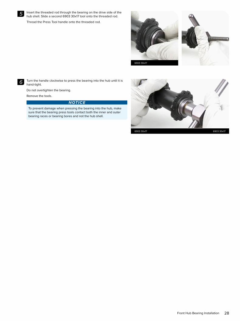
Insert the threaded rod through the bearing on the non-drive side of Insert the threaded rod through the bearing on the non-drive side of the hub shell. Slide a second 6903 30x17 tool onto the threaded rod. the hub shell. Slide a second 6903 30x17 tool onto the threaded rod.
Thread the Press Tool handle onto the threaded rod.Thread the Press Tool handle onto the threaded rod.
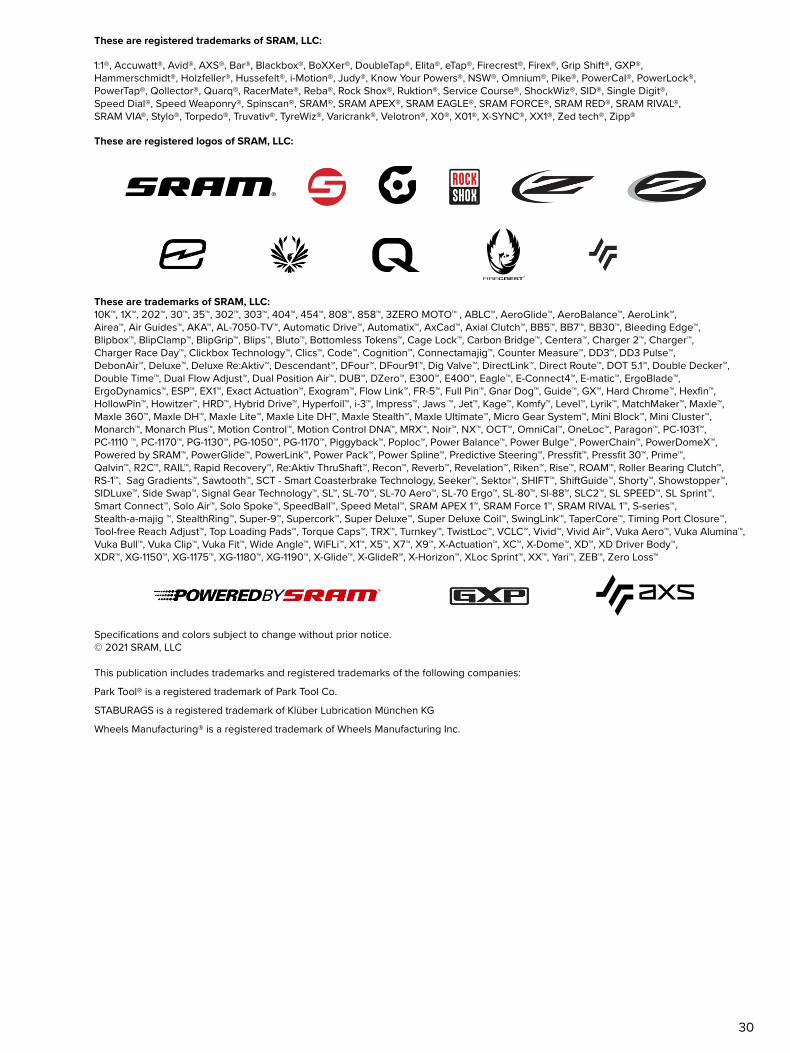
Turn the handle clockwise to press the bearing into the hub until it is Turn the handle clockwise to press the bearing into the hub until it is hand-tight. hand-tight.
Do not overtighten the bearing.Do not overtighten the bearing.
Remove the tools.Remove the tools.
NOTICETo prevent damage when pressing the bearing into the hub, make sure that the bearing press tools contact both the inner and outer bearing races or bearing bores and not the hub shell.
Place the drive side end of the axle on a flat surface. Install a new Zipp Place the drive side end of the axle on a flat surface. Install a new Zipp Cognition 6903/61903 hub bearing onto the non-drive side of the axle, Cognition 6903/61903 hub bearing onto the non-drive side of the axle, black black seal side first. Slide the bearing to the drive side of the axle, to seal side first. Slide the bearing to the drive side of the axle, to the bearing step until it stops.the bearing step until it stops.
Note:Note: Ceramic bearings have Ceramic bearings have blueblue seals on both sides of the bearing; seals on both sides of the bearing; installation orientation is not important.installation orientation is not important.
1
6903/61903 Hub Bearing 6903 30x17
2
6903 30x17
3
6903 30x17 6903 30x17
4
Zipp Cognition 6903/61903 Hub Bearing
15Rear Hub Bearing Installation
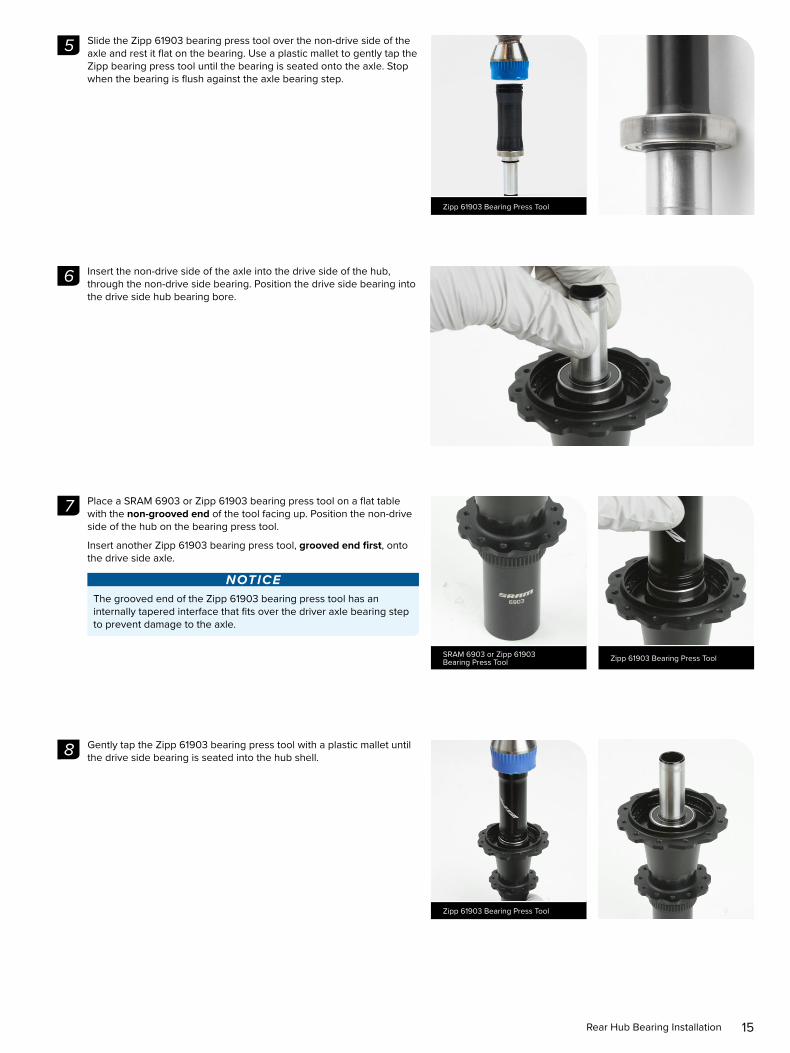
Slide the Zipp 61903 bearing press tool over the non-drive side of the Slide the Zipp 61903 bearing press tool over the non-drive side of the axle and rest it flat on the bearing. Use a plastic mallet to gently tap the axle and rest it flat on the bearing. Use a plastic mallet to gently tap the Zipp bearing press tool until the bearing is seated onto the axle. Stop Zipp bearing press tool until the bearing is seated onto the axle. Stop when the bearing is flush against the axle bearing step.when the bearing is flush against the axle bearing step.
Insert the non-drive side of the axle into the drive side of the hub, Insert the non-drive side of the axle into the drive side of the hub, through the non-drive side bearing. Position the drive side bearing into through the non-drive side bearing. Position the drive side bearing into the drive side hub bearing bore.the drive side hub bearing bore.
Place a SRAM 6903 or Zipp 61903 bearing press tool on a flat table Place a SRAM 6903 or Zipp 61903 bearing press tool on a flat table with the with the non-grooved endnon-grooved end of the tool facing up. Position the non-drive of the tool facing up. Position the non-drive side of the hub on the bearing press tool.side of the hub on the bearing press tool.
Insert another Zipp 61903 bearing press tool, Insert another Zipp 61903 bearing press tool, grooved end firstgrooved end first, onto , onto the drive side axle.the drive side axle.
NOTICEThe grooved end of the Zipp 61903 bearing press tool has an internally tapered interface that fits over the driver axle bearing step to prevent damage to the axle.
Gently tap the Zipp 61903 bearing press tool with a plastic mallet until Gently tap the Zipp 61903 bearing press tool with a plastic mallet until the drive side bearing is seated into the hub shell.the drive side bearing is seated into the hub shell.
5
Zipp 61903 Bearing Press Tool
6
7
SRAM 6903 or Zipp 61903 Bearing Press Tool Zipp 61903 Bearing Press Tool
8
Zipp 61903 Bearing Press Tool

16Rear Hub Clutch Installation
R e a r H u b C l u t c h I n s t a l l a t i o n
Install the spring assembly in to the drive side of the rear hub with the Install the spring assembly in to the drive side of the rear hub with the white surface facing down.white surface facing down.
Align the three large tabs on the Hub Shell Ratchet with the notches in Align the three large tabs on the Hub Shell Ratchet with the notches in the rear hub, and install the Hub Shell Ratchet with the angled ratchet the rear hub, and install the Hub Shell Ratchet with the angled ratchet notches facing up.notches facing up.
Install the Driver Ratchet on top of the Hub Shell Ratchet with the Install the Driver Ratchet on top of the Hub Shell Ratchet with the circular inner metal ring facing down. Gently press down on the Driver circular inner metal ring facing down. Gently press down on the Driver Ratchet to align the clutch teeth with the hub teeth.Ratchet to align the clutch teeth with the hub teeth.
Use a small syringe to apply approximately 1 mL of Zipp Cognition oil or Use a small syringe to apply approximately 1 mL of Zipp Cognition oil or Phil Bio-LubePhil Bio-Lube onto the clutch assembly, distributed evenly around the onto the clutch assembly, distributed evenly around the clutch.clutch.
Do not apply grease to the new clutch assembly.Do not apply grease to the new clutch assembly.
1
2
3
4
1 mL Zipp Cognition Oil or Phil Bio-Lube

17Rear Hub Clutch Installation
Install the clutch seal cap and press it into the hub shell.Install the clutch seal cap and press it into the hub shell.
NOTICEZipp recommends replacing the entire driver body if the bearings are worn or any part is damaged. For part numbers, refer to the Zipp Spare Parts Catalog in the Support section of www.zipp.com.
5

18Driver Installation
D r i v e r I n s t a l l a t i o n
Apply Zipp Cognition or Klüber Staburags NBU30 grease to the drive Apply Zipp Cognition or Klüber Staburags NBU30 grease to the drive side of the rear axle. Wipe away any excess grease with a shop towel.side of the rear axle. Wipe away any excess grease with a shop towel.
NOTICEDo not apply grease to the clutch or bearing.
If a brush is used to apply grease, confirm there are no loose bristles in the grease or on the part.
Clean the driver body with isopropyl alcohol and a clean shop towel.Clean the driver body with isopropyl alcohol and a clean shop towel.
NOTICEDo not apply isopropyl alcohol to the bearing.
Slide the driver assembly onto the drive side axle. Align the driver teeth Slide the driver assembly onto the drive side axle. Align the driver teeth with the clutch teeth, and press the driver into the hub shell until it is with the clutch teeth, and press the driver into the hub shell until it is seated. Press down and rotate the driver to check engagement.seated. Press down and rotate the driver to check engagement.
The procedure for driver installation is the same for each type of driver The procedure for driver installation is the same for each type of driver (SRAM 10/11 speed, SRAM XDR, and Campagnolo). The SRAM XDR (SRAM 10/11 speed, SRAM XDR, and Campagnolo). The SRAM XDR driver body is pictured.driver body is pictured.
1
Cognition / Klüber Staburags NBU30 Grease
2
3

19Rear Hub End Cap Installation
R e a r H u b E n d C a p I n s t a l l a t i o n
Install the wave spring onto the non-drive side end of the axle. Press Install the wave spring onto the non-drive side end of the axle. Press the wave spring against the bearing.the wave spring against the bearing.
Apply grease to the following locations on the drive side and non-drive Apply grease to the following locations on the drive side and non-drive side axle end:side axle end:
• Axle front surface (a) • Axle front surface (a) • Axle radial surface (b) • Axle radial surface (b) • Bearing front face across bearing seal, inner- and outer ring (c)• Bearing front face across bearing seal, inner- and outer ring (c)
NOTICEIf a brush is used to apply grease, confirm there are no loose bristles in the grease or on the part.
Install the end caps by pressing them onto the axle by hand until they Install the end caps by pressing them onto the axle by hand until they snap securely into place. Wipe away any excess grease from the hub snap securely into place. Wipe away any excess grease from the hub and end cap.and end cap.
NOTICEEnsure the o-ring is in the groove on the internal surface of the end cap before installing the end caps. Improperly installed seals may result in hub drag.
This concludes service for the rear Zipp Cognition hub.This concludes service for the rear Zipp Cognition hub.
1
Cognition / Klüber Staburags NBU30 Grease
a
c
b
2
a
cb
3
20Driver Bearing Replacement (optional)
D r i v e r B e a r i n g R e p l a c e m e n t ( o p t i o n a l )
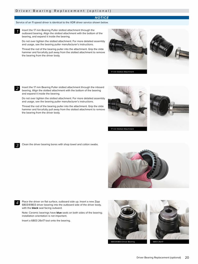
NOTICEService of an 11 speed driver is identical to the XDR driver service shown below.
Insert the 17 mm Bearing Puller slotted attachment through the Insert the 17 mm Bearing Puller slotted attachment through the outboard bearing. Align the slotted attachment with the bottom of the outboard bearing. Align the slotted attachment with the bottom of the bearing, and expand it inside the bearing.bearing, and expand it inside the bearing.
Do not over tighten the slotted attachment. For more detailed assembly Do not over tighten the slotted attachment. For more detailed assembly and usage, see the bearing puller manufacturer’s instructions.and usage, see the bearing puller manufacturer’s instructions.
Thread the rod of the bearing puller into the attachment. Grip the slide Thread the rod of the bearing puller into the attachment. Grip the slide hammer and forcefully pull away from the slotted attachment to remove hammer and forcefully pull away from the slotted attachment to remove the bearing from the driver body.the bearing from the driver body.
Insert the 17 mm Bearing Puller slotted attachment through the inboard Insert the 17 mm Bearing Puller slotted attachment through the inboard bearing. Align the slotted attachment with the bottom of the bearing bearing. Align the slotted attachment with the bottom of the bearing and expand it inside the bearing.and expand it inside the bearing.
Do not over tighten the slotted attachment. For more detailed assembly Do not over tighten the slotted attachment. For more detailed assembly and usage, see the bearing puller manufacturer’s instructions.and usage, see the bearing puller manufacturer’s instructions.
Thread the rod of the bearing puller into the attachment. Grip the slide Thread the rod of the bearing puller into the attachment. Grip the slide hammer and forcefully pull away from the slotted attachment to remove hammer and forcefully pull away from the slotted attachment to remove the bearing from the driver body.the bearing from the driver body.
Clean the driver bearing bores with shop towel and cotton swabs.Clean the driver bearing bores with shop towel and cotton swabs.
Place the driver on flat surface, outboard side up. Insert a new Zipp Place the driver on flat surface, outboard side up. Insert a new Zipp 6803/61803 driver bearing into the outboard side of the driver body, 6803/61803 driver bearing into the outboard side of the driver body, with the with the blackblack seal facing outward. seal facing outward.
Note: Ceramic bearings have Note: Ceramic bearings have blueblue seals on both sides of the bearing; seals on both sides of the bearing; installation orientation is not important.installation orientation is not important.
Insert a 6803 26x17 tool onto the bearing.Insert a 6803 26x17 tool onto the bearing.
1
17 mm Slotted Attachment
2
17 mm Slotted Attachment
3
4
6803/61803 Driver Bearing 6803 26x17
21Driver Bearing Replacement (optional)
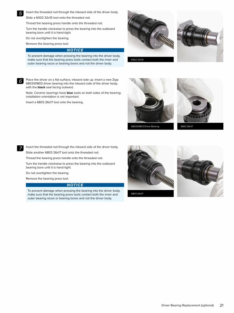
Insert the threaded rod through the inboard side of the driver body.Insert the threaded rod through the inboard side of the driver body.
Slide a 6002 32x15 tool onto the threaded rod.Slide a 6002 32x15 tool onto the threaded rod.
Thread the bearing press handle onto the threaded rod.Thread the bearing press handle onto the threaded rod.
Turn the handle clockwise to press the bearing into the outboard Turn the handle clockwise to press the bearing into the outboard bearing bore until it is hand-tight.bearing bore until it is hand-tight.
Do not overtighten the bearing.Do not overtighten the bearing.
Remove the bearing press tool.Remove the bearing press tool.
NOTICETo prevent damage when pressing the bearing into the driver body, make sure that the bearing press tools contact both the inner and outer bearing races or bearing bores and not the driver body.
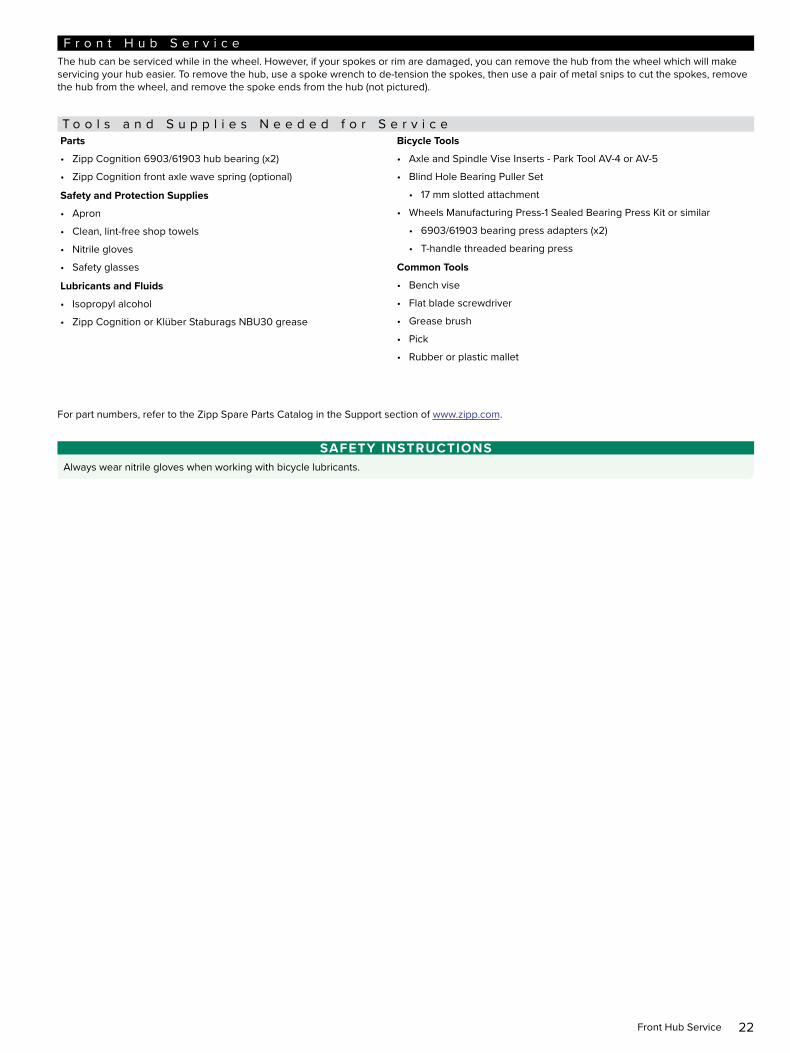
Place the driver on a flat surface, inboard side up. Insert a new Zipp Place the driver on a flat surface, inboard side up. Insert a new Zipp 6803/61803 driver bearing into the inboard side of the driver body, 6803/61803 driver bearing into the inboard side of the driver body, with the with the blackblack seal facing outward. seal facing outward.
Note: Ceramic bearings have Note: Ceramic bearings have blueblue seals on both sides of the bearing; seals on both sides of the bearing; installation orientation is not important.installation orientation is not important.
Insert a 6803 26x17 tool onto the bearing.Insert a 6803 26x17 tool onto the bearing.
Insert the threaded rod through the inboard side of the driver body.Insert the threaded rod through the inboard side of the driver body.
Slide another 6803 26x17 tool onto the threaded rod.Slide another 6803 26x17 tool onto the threaded rod.
Thread the bearing press handle onto the threaded rod.Thread the bearing press handle onto the threaded rod.
Turn the handle clockwise to press the bearing into the outboard Turn the handle clockwise to press the bearing into the outboard bearing bore until it is hand-tight.bearing bore until it is hand-tight.
Do not overtighten the bearing.Do not overtighten the bearing.
Remove the bearing press tool.Remove the bearing press tool.
NOTICETo prevent damage when pressing the bearing into the driver body, make sure that the bearing press tools contact both the inner and outer bearing races or bearing bores and not the driver body.
5
6002 32x15
6
6803/61803 Driver Bearing 6803 26x17
7
6803 26x17
22Front Hub Service
F r o n t H u b S e r v i c eThe hub can be serviced while in the wheel. However, if your spokes or rim are damaged, you can remove the hub from the wheel which will make servicing your hub easier. To remove the hub, use a spoke wrench to de-tension the spokes, then use a pair of metal snips to cut the spokes, remove the hub from the wheel, and remove the spoke ends from the hub (not pictured).
T o o l s a n d S u p p l i e s N e e d e d f o r S e r v i c eParts
• Zipp Cognition 6903/61903 hub bearing (x2)
• Zipp Cognition front axle wave spring (optional)
Safety and Protection Supplies
• Apron
• Clean, lint-free shop towels
• Nitrile gloves
• Safety glasses
Lubricants and Fluids
• Isopropyl alcohol
• Zipp Cognition or Klüber Staburags NBU30 grease
Bicycle Tools
• Axle and Spindle Vise Inserts - Park Tool AV-4 or AV-5
• Blind Hole Bearing Puller Set
• 17 mm slotted attachment
• Wheels Manufacturing Press-1 Sealed Bearing Press Kit or similar
• 6903/61903 bearing press adapters (x2)
• T-handle threaded bearing press
Common Tools
• Bench vise
• Flat blade screwdriver
• Grease brush
• Pick
• Rubber or plastic mallet
For part numbers, refer to the Zipp Spare Parts Catalog in the Support section of www.zipp.com.
SAFETY INSTRUCTIONSAlways wear nitrile gloves when working with bicycle lubricants.
23Front Disc Brake Hub Exploded View
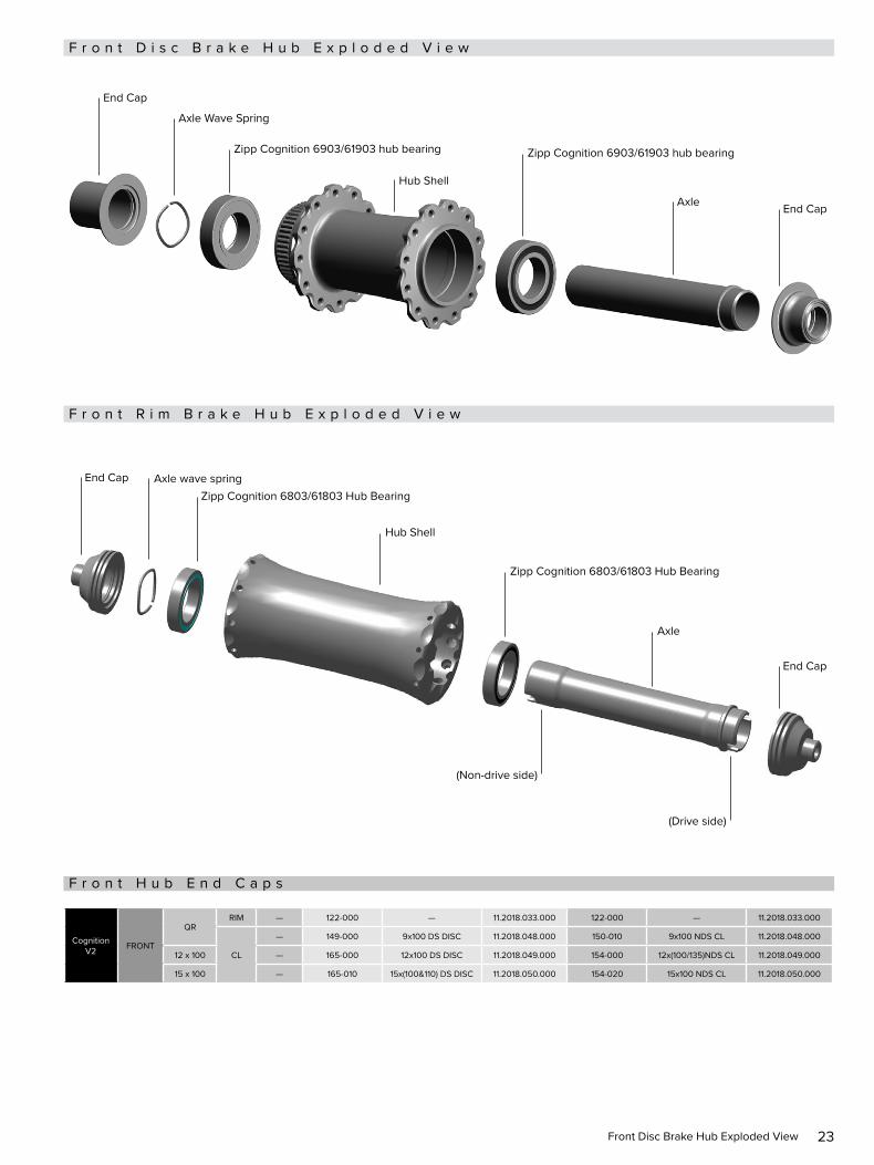
F r o n t D i s c B r a k e H u b E x p l o d e d V i e w
F r o n t R i m B r a k e H u b E x p l o d e d V i e w
Axle wave springZipp Cognition 6803/61803 Hub Bearing
Zipp Cognition 6803/61803 Hub Bearing
Hub Shell
Axle
(Non-drive side)
(Drive side)
End Cap
End Cap
F r o n t H u b E n d C a p s
Cognition V2 FRONT
QRRIM — 122-000 — 11.2018.033.000 122-000 — 11.2018.033.000
CL
— 149-000 9x100 DS DISC 11.2018.048.000 150-010 9x100 NDS CL 11.2018.048.000
12 x 100 — 165-000 12x100 DS DISC 11.2018.049.000 154-000 12x(100/135)NDS CL 11.2018.049.000
15 x 100 — 165-010 15x(100&110) DS DISC 11.2018.050.000 154-020 15x100 NDS CL 11.2018.050.000
Hub Shell
Axle Wave Spring
End Cap
End Cap
Zipp Cognition 6903/61903 hub bearing Zipp Cognition 6903/61903 hub bearing
Axle
24Front Hub Disassembly
F r o n t H u b D i s a s s e m b l y
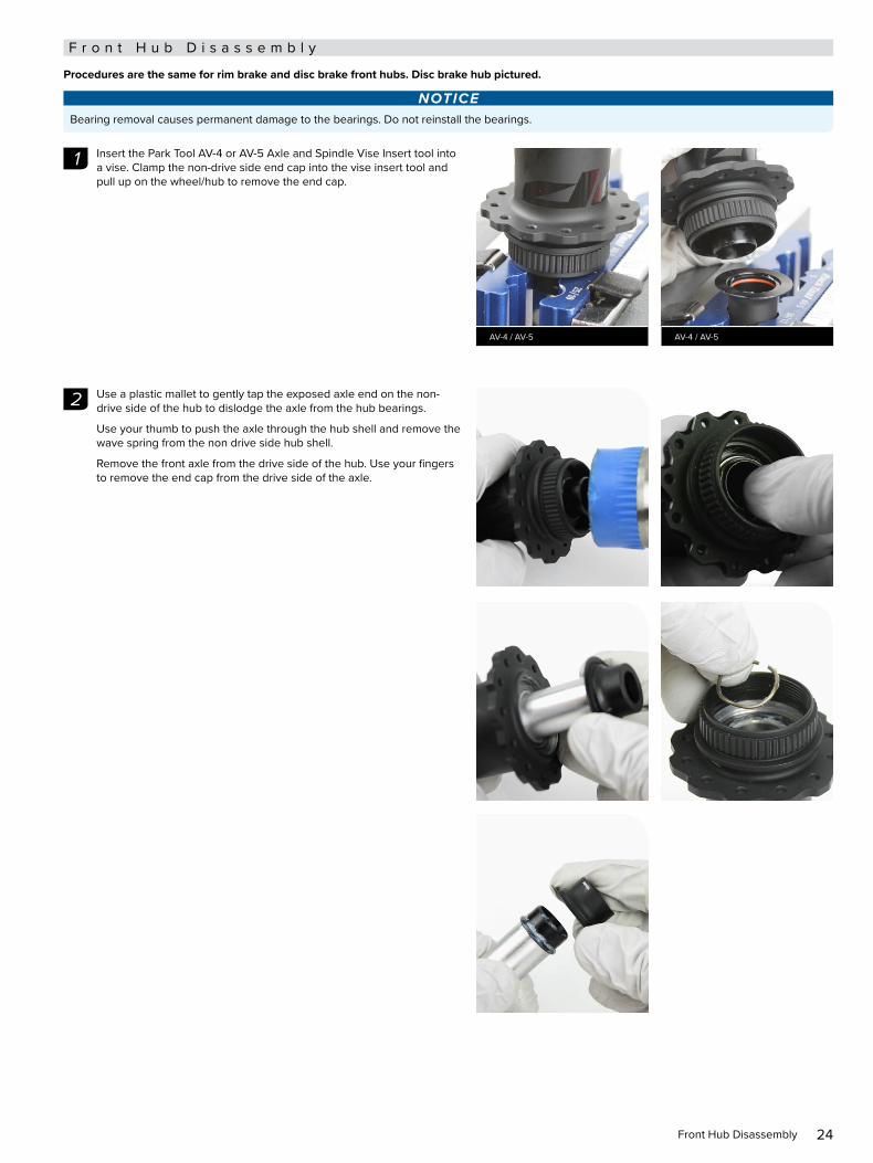
Procedures are the same for rim brake and disc brake front hubs. Disc brake hub pictured.
NOTICEBearing removal causes permanent damage to the bearings. Do not reinstall the bearings.
Insert the Park Tool AV-4 or AV-5 Axle and Spindle Vise Insert tool into Insert the Park Tool AV-4 or AV-5 Axle and Spindle Vise Insert tool into a vise. Clamp the non-drive side end cap into the vise insert tool and a vise. Clamp the non-drive side end cap into the vise insert tool and pull up on the wheel/hub to remove the end cap.pull up on the wheel/hub to remove the end cap.
Use a plastic mallet to gently tap the exposed axle end on the non-Use a plastic mallet to gently tap the exposed axle end on the non-drive side of the hub to dislodge the axle from the hub bearings.drive side of the hub to dislodge the axle from the hub bearings.
Use your thumb to push the axle through the hub shell and remove the Use your thumb to push the axle through the hub shell and remove the wave spring from the non drive side hub shell.wave spring from the non drive side hub shell.
Remove the front axle from the drive side of the hub. Use your fingers Remove the front axle from the drive side of the hub. Use your fingers to remove the end cap from the drive side of the axle.to remove the end cap from the drive side of the axle.
1
AV-4 / AV-5 AV-4 / AV-5
2

25Front Hub Disassembly
Spray isopropyl alcohol onto the axle and clean the axle with a shop Spray isopropyl alcohol onto the axle and clean the axle with a shop towel.towel.
NOTICETo prevent damage to the hub surfaces, do not use Acetone or similar products to clean parts.
Insert the 17 mm slotted bearing puller attachment through either hub Insert the 17 mm slotted bearing puller attachment through either hub bearing. Align the slotted attachment with the bottom of the bearing, bearing. Align the slotted attachment with the bottom of the bearing, then tighten the slotted attachment to expand the puller inside the then tighten the slotted attachment to expand the puller inside the bearing.bearing.
NOTICEDo not over tighten the slotted attachment. For more detailed assembly and usage information, consult your bearing puller's manufacturer's instructions.
Thread the shaft of the bearing puller into the slotted attachment. While Thread the shaft of the bearing puller into the slotted attachment. While holding the hub securely, forcefully pull back on the slide hammer to holding the hub securely, forcefully pull back on the slide hammer to remove the bearing from the drive side of the hub shell.remove the bearing from the drive side of the hub shell.
Remove the bearing from the slotted attachment.Remove the bearing from the slotted attachment.
Discard the bearing.Discard the bearing.
Insert the 17 mm slotted bearing puller attachment through either hub Insert the 17 mm slotted bearing puller attachment through either hub bearing. Align the slotted attachment with the bottom of the bearing, bearing. Align the slotted attachment with the bottom of the bearing, then tighten the slotted attachment to expand the puller inside the then tighten the slotted attachment to expand the puller inside the bearing.bearing.
NOTICEDo not over tighten the slotted attachment. For more detailed assembly and usage information, consult your bearing puller's manufacturer's instructions.
3
Isopropyl Alcohol
4
17 mm Slotted Bearing Puller
5
Slide Hammer Bearing Puller
6
17 mm Slotted Bearing Puller

26Front Hub Disassembly
Thread the shaft of the bearing puller into the slotted attachment. While Thread the shaft of the bearing puller into the slotted attachment. While holding the hub securely, forcefully pull back on the slide hammer to holding the hub securely, forcefully pull back on the slide hammer to remove the bearing from the drive side of the hub shell.remove the bearing from the drive side of the hub shell.
Remove the bearing from the slotted attachment.Remove the bearing from the slotted attachment.
Discard the bearing.Discard the bearing.
Spray isopropyl alcohol in the front hub bearing bores and clean them Spray isopropyl alcohol in the front hub bearing bores and clean them with a shop towel.with a shop towel.
7
Slide Hammer Bearing Puller
8
Isopropyl Alcohol

27Front Hub Bearing Installation
F r o n t H u b B e a r i n g I n s t a l l a t i o n
Use only Zipp Cognition replacement bearings in Zipp Cognition hubs.
Place the hub on flat surface, non-drive side up. Insert a new Zipp Place the hub on flat surface, non-drive side up. Insert a new Zipp Cognition 6903/61903 hub bearing into the non-drive side of the hub Cognition 6903/61903 hub bearing into the non-drive side of the hub shell, with the shell, with the black black seal facing outward.seal facing outward.
Note:Note: Ceramic bearings have Ceramic bearings have blueblue seals on both sides of the bearing; seals on both sides of the bearing; installation orientation is not important.installation orientation is not important.
Insert a 6903 30x17 tool onto the bearing.Insert a 6903 30x17 tool onto the bearing.
Insert the threaded rod through the bearing on the non-drive side of Insert the threaded rod through the bearing on the non-drive side of the hub shell. Slide a second 6903 30x17 tool onto the threaded rod. the hub shell. Slide a second 6903 30x17 tool onto the threaded rod.
Thread the Press Tool handle onto the threaded rod.Thread the Press Tool handle onto the threaded rod.
Turn the handle clockwise to press the bearing into the hub until it is Turn the handle clockwise to press the bearing into the hub until it is hand-tight. hand-tight.
Do not overtighten the bearing.Do not overtighten the bearing.
Remove the tools.Remove the tools.
NOTICETo prevent damage when pressing the bearing into the hub, make sure that the bearing press tools contact both the inner and outer bearing races or bearing bores and not the hub shell.
Place the hub on flat surface, drive side up. Insert a new Zipp Cognition Place the hub on flat surface, drive side up. Insert a new Zipp Cognition 6903/61903 hub bearing into the drive side of the hub shell, with the 6903/61903 hub bearing into the drive side of the hub shell, with the black black seal facing outward.seal facing outward.
Note:Note: Ceramic bearings have Ceramic bearings have blueblue seals on both sides of the bearing; seals on both sides of the bearing; installation orientation is not important.installation orientation is not important.
Insert a 6903 30x17 tool onto the bearing.Insert a 6903 30x17 tool onto the bearing.
1
6903/61903 Hub Bearing 6903 30x17
2
6903 30x17
3
6903 30x17 6903 30x17
4
6903/61903 Hub Bearing 6903 30x17
28Front Hub Bearing Installation
Insert the threaded rod through the bearing on the drive side of the Insert the threaded rod through the bearing on the drive side of the hub shell. Slide a second 6903 30x17 tool onto the threaded rod. hub shell. Slide a second 6903 30x17 tool onto the threaded rod.
Thread the Press Tool handle onto the threaded rod.Thread the Press Tool handle onto the threaded rod.
Turn the handle clockwise to press the bearing into the hub until it is Turn the handle clockwise to press the bearing into the hub until it is hand-tight. hand-tight.
Do not overtighten the bearing.Do not overtighten the bearing.
Remove the tools.Remove the tools.
NOTICETo prevent damage when pressing the bearing into the hub, make sure that the bearing press tools contact both the inner and outer bearing races or bearing bores and not the hub shell.
5
6903 30x17
6
6903 30x17 6903 30x17

29Front Hub Axle and End Cap Installation
F r o n t H u b A x l e a n d E n d C a p I n s t a l l a t i o n
Insert the non-drive side end of the axle into drive side of the hub, Insert the non-drive side end of the axle into drive side of the hub, through the drive side bearing, through the hub, and through the through the drive side bearing, through the hub, and through the non-drive side bearing. Press the axle into the hub bearing with your non-drive side bearing. Press the axle into the hub bearing with your thumb until the axle bearing step fits flush into the bearing.thumb until the axle bearing step fits flush into the bearing.
Install the wave spring onto the non-drive side end of the axle. Press Install the wave spring onto the non-drive side end of the axle. Press the wave spring against the bearing.the wave spring against the bearing.
Apply grease to the following locations on the drive side and non-drive Apply grease to the following locations on the drive side and non-drive side axle end:side axle end:
• Axle front surface (a) • Axle front surface (a) • Axle radial surface (b) • Axle radial surface (b) • Bearing front face across bearing seal, inner- and outer ring (c)• Bearing front face across bearing seal, inner- and outer ring (c)
Install the end caps by pressing them onto the axle by hand until they Install the end caps by pressing them onto the axle by hand until they snap securely into place. Wipe away any excess grease from the hub snap securely into place. Wipe away any excess grease from the hub and end cap.and end cap.
NOTICEEnsure the o-ring is in the groove on the internal surface of the end cap before installing the end caps. Improperly installed seals may result in hub drag.
This concludes service for the front Zipp Cognition hub.This concludes service for the front Zipp Cognition hub.
1
2
3 4
Cognition / Klüber Staburags NBU30 Grease
a
cb
5
30
These are registered trademarks of SRAM, LLC:
1:1®, Accuwatt®, Avid®, AXS®, Bar®, Blackbox®, BoXXer®, DoubleTap®, Elita®, eTap®, Firecrest®, Firex®, Grip Shift®, GXP®, Hammerschmidt®, Holzfeller®, Hussefelt®, i-Motion®, Judy®, Know Your Powers®, NSW®, Omnium®, Pike®, PowerCal®, PowerLock®, PowerTap®, Qollector®, Quarq®, RacerMate®, Reba®, Rock Shox®, Ruktion®, Service Course®, ShockWiz®, SID®, Single Digit®, Speed Dial®, Speed Weaponry®, Spinscan®, SRAM®, SRAM APEX®, SRAM EAGLE®, SRAM FORCE®, SRAM RED®, SRAM RIVAL®, SRAM VIA®, Stylo®, Torpedo®, Truvativ®, TyreWiz®, Varicrank®, Velotron®, X0®, X01®, X-SYNC®, XX1®, Zed tech®, Zipp®
These are registered logos of SRAM, LLC:
These are trademarks of SRAM, LLC:10K™, 1X™, 202™, 30™, 35™, 302™, 303™, 404™, 454™, 808™, 858™, 3ZERO MOTO™ , ABLC™, AeroGlide™, AeroBalance™, AeroLink™, Airea™, Air Guides™, AKA™, AL-7050-TV™, Automatic Drive™, Automatix™, AxCad™, Axial Clutch™, BB5™, BB7™, BB30™, Bleeding Edge™, Blipbox™, BlipClamp™, BlipGrip™, Blips™, Bluto™, Bottomless Tokens™, Cage Lock™, Carbon Bridge™, Centera™, Charger 2™, Charger™, Charger Race Day™, Clickbox Technology™, Clics™, Code™, Cognition™, Connectamajig™, Counter Measure™, DD3™, DD3 Pulse™, DebonAir™, Deluxe™, Deluxe Re:Aktiv™, Descendant™, DFour™, DFour91™, Dig Valve™, DirectLink™, Direct Route™, DOT 5.1™, Double Decker™, Double Time™, Dual Flow Adjust™, Dual Position Air™, DUB™, DZero™, E300™, E400™, Eagle™, E-Connect4™, E-matic™, ErgoBlade™, ErgoDynamics™, ESP™, EX1™, Exact Actuation™, Exogram™, Flow Link™, FR-5™, Full Pin™, Gnar Dog™, Guide™, GX™, Hard Chrome™, Hexfin™, HollowPin™, Howitzer™, HRD™, Hybrid Drive™, Hyperfoil™, i-3™, Impress™, Jaws ™, Jet™, Kage™, Komfy™, Level™, Lyrik™, MatchMaker™, Maxle™, Maxle 360™, Maxle DH™, Maxle Lite™, Maxle Lite DH™, Maxle Stealth™, Maxle Ultimate™, Micro Gear System™, Mini Block™, Mini Cluster™, Monarch™, Monarch Plus™, Motion Control™, Motion Control DNA™, MRX™, Noir™, NX™, OCT™, OmniCal™, OneLoc™, Paragon™, PC-1031™, PC-1110 ™, PC-1170™, PG-1130™, PG-1050™, PG-1170™, Piggyback™, Poploc™, Power Balance™, Power Bulge™, PowerChain™, PowerDomeX™, Powered by SRAM™, PowerGlide™, PowerLink™, Power Pack™, Power Spline™, Predictive Steering™, Pressfit™, Pressfit 30™, Prime™, Qalvin™, R2C™, RAIL™, Rapid Recovery™, Re:Aktiv ThruShaft™, Recon™, Reverb™, Revelation™, Riken™, Rise™, ROAM™, Roller Bearing Clutch™, RS-1™, Sag Gradients™, Sawtooth™, SCT - Smart Coasterbrake Technology, Seeker™, Sektor™, SHIFT™, ShiftGuide™, Shorty™, Showstopper™, SIDLuxe™, Side Swap™, Signal Gear Technology™, SL™, SL-70™, SL-70 Aero™, SL-70 Ergo™, SL-80™, Sl-88™, SLC2™, SL SPEED™, SL Sprint™, Smart Connect™, Solo Air™, Solo Spoke™, SpeedBall™, Speed Metal™, SRAM APEX 1™, SRAM Force 1™, SRAM RIVAL 1™, S-series™, Stealth-a-majig ™, StealthRing™, Super-9™, Supercork™, Super Deluxe™, Super Deluxe Coil™, SwingLink™, TaperCore™, Timing Port Closure™, Tool-free Reach Adjust™, Top Loading Pads™, Torque Caps™, TRX™, Turnkey™, TwistLoc™, VCLC™, Vivid™, Vivid Air™, Vuka Aero™, Vuka Alumina™, Vuka Bull™, Vuka Clip™, Vuka Fit™, Wide Angle™, WiFLi™, X1™, X5™, X7™, X9™, X-Actuation™, XC™, X-Dome™, XD™, XD Driver Body™, XDR™, XG-1150™, XG-1175™, XG-1180™, XG-1190™, X-Glide™, X-GlideR™, X-Horizon™, XLoc Sprint™, XX™, Yari™, ZEB™, Zero Loss™
Specifications and colors subject to change without prior notice.© 2021 SRAM, LLC
This publication includes trademarks and registered trademarks of the following companies:
Park Tool® is a registered trademark of Park Tool Co.
STABURAGS is a registered trademark of Klüber Lubrication München KG
Wheels Manufacturing® is a registered trademark of Wheels Manufacturing Inc.

ASIAN HEADQUARTERS SRAM Taiwan No. 1598-8 Chung Shan Road Shen Kang Hsiang, Taichung City Taiwan R.O.C.
WORLD HEADQUARTERS SRAM LLC 1000 W. Fulton Market, 4th Floor Chicago, Illinois 60607 U.S.A.
EUROPEAN HEADQUARTERS SRAM Europe Paasbosweg 14-16 3862ZS Nijkerk The Netherlands