cognitive single carrier systems: joint impact of … · cognitive single carrier systems: joint...
TRANSCRIPT

MITSUBISHI ELECTRIC RESEARCH LABORATORIEShttp://www.merl.com
Cognitive Single Carrier Systems: Joint Impact of MultipleLicensed Transceivers
Kim, K.J.; Wang, L.; Duong, T.Q.; Elkashlan, M.; Poor, H.V.
TR2014-089 December 2014
AbstractIn this paper, the impact of interference from multiple licensed transceivers on cognitive un-derlay single-carrier systems is examined. Specifically, the situation is considered in which thesecondary network is limited by three key parameters: 1) maximum transmit power at thesecondary transmitter, 2) peak interference power at the primary receivers, and 3) interfer-ence power from the primary transmitters. For this cognitive underlay single-carrier system,the signal-to-interference ratio (SIR) of the secondary network is obtained for transmissionover frequency-selective fading channels. Based on this, a new closed-form expression for thecumulative distribution function of the SIR is evaluated, from which the outage probabil-ity and the ergodic capacity are derived. Further insights are established by analyzing theasymptotic outage probability and the asymptotic ergodic capacity in the high-transmission-power regime. In particular, it is corroborated that the asymptotic outage diversity gain isequal to the multipath gain of the frequency-selective channel in the secondary network. Theasymptotic ergodic capacity also gives new insight into the additional power cost for differentnetwork parameters while maintaining a specified target ergodic capacity. Illustrative nu-merical examples are presented to validate the outage probability and ergodic capacity underdifferent interference power profiles.
IEEE Transactions on Wireless Communications
This work may not be copied or reproduced in whole or in part for any commercial purpose. Permission to copy inwhole or in part without payment of fee is granted for nonprofit educational and research purposes provided that allsuch whole or partial copies include the following: a notice that such copying is by permission of Mitsubishi ElectricResearch Laboratories, Inc.; an acknowledgment of the authors and individual contributions to the work; and allapplicable portions of the copyright notice. Copying, reproduction, or republishing for any other purpose shall requirea license with payment of fee to Mitsubishi Electric Research Laboratories, Inc. All rights reserved.
Copyright c© Mitsubishi Electric Research Laboratories, Inc., 2014201 Broadway, Cambridge, Massachusetts 02139


Cognitive Single Carrier Systems: Joint Impact ofMultiple Licensed Transceivers
Kyeong Jin Kim, Senior Member, IEEE, Lifeng Wang, Student Member, IEEE,Trung Q. Duong, Senior Member, IEEE, Maged Elkashlan, Member, IEEE, and
H. Vincent Poor Fellow, IEEE
Abstract—In this paper, the impact of interference frommultiple licensed transceivers on cognitive underlay single carriersystems is examined. Specifically, the situation is considered inwhich the secondary network is limited by three key parameters:1) maximum transmit power at the secondary transmitter, 2)peak interference power at the primary receivers, and 3) inter-ference power from the primary transmitters. For this cognitiveunderlay single carrier system, the signal-to-interference ratio(SIR) of the secondary network is obtained for transmission overfrequency selective fading channels. Based on this, a new closed-form expression for the cumulative distribution function of theSIR is evaluated, from which the outage probability and theergodic capacity are derived. Further insights are established byanalyzing the asymptotic outage probability and the asymptoticergodic capacity in the high transmission power regime. Inparticular, it is corroborated that the asymptotic outage diversitygain is equal to the multipath gain of the frequency selectivechannel in the secondary network. The asymptotic ergodiccapacity also gives new insight into the additional power cost fordifferent network parameters while maintaining a specified targetergodic capacity. Illustrative numerical examples are presentedto validate the outage probability and ergodic capacity underdifferent interference power profiles.
Index Terms—Cognitive radio, ergodic capacity, frequencyselective fading, outage probability, primary transceivers, singlecarrier transmission.
I. INTRODUCTION
RADIO frequency spectrum is an increasingly scarceand expensive wireless resource due to the upsurge in
demand for multimedia services in current and future gen-eration wireless networks. Unfortunately, recent measurementcampaigns have found that the radio frequency spectrum is notbeing efficiently utilized [1]–[7]. Cognitive radio, proposed byMitola in [8], has the potential to mitigate such inefficiency.Particularly, by allowing a secondary user (SU) to reuse theradio spectrum that is licensed to a primary user (PU), thescarcity of frequency spectrum can be alleviated. Several
Manuscript received November 27, 2013; revised March 18, 2014; acceptedMay 7, 2014. The editor coordinating the review of this paper and approvingit for publication was Prof. Y. Sanada.
K. J. Kim is with Mitsubishi Electric Research Laboratories (MERL),Cambridge, MA, USA. Part of this work was completed while he was inInha University, Korea.
L. Wang and M. Elkashlan are with Queen Mary University of London,London, UK.
T. Q. Duong is with Queen’s University Belfast, Belfast, UK.H. V. Poor is with the Department of Electrical Engineering, Princeton
University, Princeton, NJ, USA.This research was supported in part by the U. S. National Science
Foundation under Grant ECCS-1343210.
approaches to cognitive radio such as overlay, interweave, andunderlay spectrum sharing have been considered [9]. Amongthem, the most promising approach is underlay spectrum shar-ing in which the SU simultaneously transmits in the same radiospectrum as the PU, provided that the secondary transmissiondoes not exceed the maximum interference constraint set bythe primary network [10]. One of the drawbacks of underlayspectrum sharing is the need to limit the transmit power ofthe SU transmitter (SU-Tx) to avoid any deleterious effecton the PU receiver (PU-Rx). In some practical scenarios, thecognitive radio network may not be feasible due to heavypathloss and severe shadowing [11]. As such, several advancedtransmission technologies have been introduced to enhance theperformance of underlay spectrum sharing such as cognitiverelaying [12] and cognitive multiuser diversity [13].
Cognitive underlay spectrum sharing with single carriertransmission was first considered in [14]. Since then, promis-ing strategies for cognitive underlay single carrier systemshave been proposed such as cognitive relay selection [15] andcognitive decode-and-forward (DF) with selection combining[16]. Indeed, cognitive underlay spectrum sharing has beenproven to boost the outage probability, ergodic capacity, andaverage symbol error rate (ASER) of single carrier systemsrelative to non-spectrum sharing single carrier systems [17]–[20]. In [14]–[16], only a single PU-Rx is considered, whilemultiple PU-Rxs are considered in non-single carrier transmis-sion in [21]. Furthermore, most previous works assume thatthe PU transmitter (PU-Tx) is located far enough away so asnot to impinge any significant interference on the SU receiver(SU-Rx) [22]. As such, only limited studies have taken intoaccount the interference from either a single or multiple PU-Txs (e.g., [14], [21], [23]).
In this paper, in contrast to [14]–[25], we focus on theco-existence of multiple PU-Rxs and multiple interfering PU-Txs in cognitive underlay single carrier systems. We considerthe practical case of non-identical frequency selective fadingbetween all the PUs and the SUs.1 Thus, compared withexisting works in [13-15], [20], and [21], the impact ofmultiple licensed primary transceivers on the performance ofspectrum sharing single carrier systems in frequency selectivefading channels is first investigated in this paper under a jointconstraint on peak interference power at the primary receiverand maximum transmit power at the secondary user. Specifi-
1For non-spectrum sharing systems, the effects of cochannel interference(CCI) have been examined under identical frequency selective fading in [20]and non-identical Nakagami-m fading in [26].
1

2
cally, the novel contributions of this paper are summarized asfollows:
• We consider the joint impact of multiple PU-Txs andmultiple PU-Rxs on the performance of cognitive under-lay single carrier systems. Motivated by [15] and [21],we employ three interrelated power constraints, namely,the interference power from the PU-Txs on the SU-Rx,denoted by PIp , the peak interference power from theSU-Tx on the PU-Rxs, denoted by Ip, and the maximumtransmit power at the SU-Tx, denoted by PT .
• We characterize the end-to-end signal-to-interference plusnoise ratio (SINR) at the SU-Rx in terms of the chan-nel impulse responses of the frequency selective fadingchannels. Using this statistic, new analytical expressionsfor the outage probability and the ergodic capacity areobtained. These results are used to evaluate the impactof the multiple PU-Txs and PU-Rxs on the secondarynetwork.
• We derive the asymptotic outage probability in the hightransmission power regime. This reveals additional in-sights into the diversity gain, which is equal to themultipath gain of the frequency selective channel in thesecondary network. Interestingly, we confirm that thediversity gain is lost when the interference power from thePU-Txs is proportional to the maximum transmit powerat the SU-Tx.
• We derive the asymptotic ergodic capacity in the hightransmission power regime under the proportional in-terference power constraint. Using this new result, weconfirm that the multiplexing gain is 1. Moreover, given aspecified target ergodic capacity, we accurately calculatethe additional power cost for different network parame-ters.
Notation: The superscript (·)H denotes complex conjugatetransposition; IN is an N × N identity matrix; 0 denotesan all-zeros matrix of appropriate dimensions; CN
(µ, σ2
)denotes the complex Gaussian distribution with mean µ andvariance σ2; Cm×n denotes the vector space of all m × ncomplex matrices; Fφ(·) denotes the cumulative distributionfunction (CDF) of the random variable (RV) φ; Ea· denotesexpectation with respect to a. The probability density function(PDF) of φ is denoted by fφ(·).
The rest of the paper is organized as follows. In Section II,we first detail the system and channel model of the proposedcognitive underlay single carrier systems. In Section III, theSINR and signal-to-interference ratio (SIR) are defined, basedon which the outage probability and ergodic capacity arederived. Simulation results are presented in Section IV, andconclusions are drawn in Section V.
II. SYSTEM AND CHANNEL MODEL
We assume a single antenna equipped cognitive underlaysingle carrier system with M PU-Txs transmitting to NPU-Rxs in the primary network. In the secondary network,we consider that the SU-Tx transmits to the SU-Rx in thesame primary licensed frequency band subject to interferenceconstraints imposed by the PU-Rxs. Unlike [12], [22], [24],
SU-Tx SU-Rx
1
1
N
M
h
1
1
M
N
Fig. 1. Illustration of the spectrum sharing single carrier network withmultiple PU-Rxs and multiple PU-Txs.
and [25] which ignored interference from the PU-Txs, weconsider that all PU-Txs impinge significant interference uponthe received signals at the SU-Rx. The set of instantaneousimpulse channel responses in the system are detailed asfollows:
• The frequency selective channel from the SU-Txto the SU-Rx is defined by a channel vectorh
=[h0, ..., hL1−1]
T ∈ CL1×1. The path loss and themultipath channel length of h are denoted by αh andL1, respectively.
• The frequency selective interfering channel from the kthPU-Txk to the SU-Rx is defined by a channel vectorfk
=[fk,0, ..., fk,L2−1]
T ∈ CL2×1. The path loss overthe channel fk and the multipath channel length of allfkMk=1 are denoted by αf,k and L2, respectively.
• The frequency selective interfering channel fromthe SU-Tx to the kth PU-Rxk is defined bygk
=[gk,0, ..., gk,L3−1]
T ∈ CL3×1. The path lossover the channel gk and the multipath channel length ofall gkNk=1 are denoted by αg,k and L3, respectively.
Recall that we denote the maximum transmit power at theSU-Tx by PT and the peak allowable interference at all thePU-Rxs by Ip. Given these two distinctive constraints, thetransmit power at the SU-Tx is defined as [15], [27]
Ps = min(PT ,
Ip
maxk=1,··· ,N
αg,k∥gk∥2
). (1)
Binary phase shift keying (BPSK) modulation is applied suchthat Q modulated data symbols transmitted by the PU-Tx forma transmit symbol block x ∈ CQ×1 ∈ −1, 1Q satisfyingExx = 0 and ExxxH = IQ. A cyclic prefix (CP)comprising of Qg symbols is appended to the front of x toprevent inter-block symbol interference (IBSI) [28], [29]. Afterremoving the signal associated with the CP, the received signalat the SU-Rx can be written as
y =√PsαhHx+
M∑p=1
√PIpαf,pFpxp + z (2)
3
where PIp is the interference power from the pth PU-Tx, H ∈CQ×Q is the right circulant channel matrix [14], [30] specifiedby h, FpKp=1 ∈ CQ×Q is the set of right circulant channelmatrices specified by fpKp=1, and z ∼ CN (0, σ2
nIQ) denotesadditive white Gaussian noise at the SU-Rx. We define theinterfering transmit symbol from the PU-Tx as xp ∈ CQ×1
which satisfies Expxp = 0 and ExpxpxHp = IQ. Since,
in general, maxL1, L2, L3 is smaller than the block size Q,a necessary zero padding is required for h, fp, and gkto form a Q×Q circulant channel matrix.
To determine the effects of the PU-Tx interference on thesecondary network, we shall first define the instantaneousSINR at the SU-Rx as follows.
Definition 1: Applying the properties of the right circulantchannel matrix 2 [14], [30] and the frequency selective channelmodels given above, the instantaneous SINR is defined as
γSINR =
min(PT ,
Ip
maxk=1,··· ,N
αg,k∥gk∥2
)αh∥h∥2
∑Mp=1 PIp αf,p∥fp∥2 + 1
≈
min(PT ,
Ip
maxk=1,··· ,N
αg,k∥gk∥2
)αh∥h∥2
∑Mp=1 PIp αf,p∥fp∥2
= min(PT ,
IpX
)Y
= γ (3)
where γ is the instantaneous SIR normalized by the noisevariance. We define X
= max
k=1,··· ,Nαg,k∥gk∥2 and Y
=A
B
with A=αh∥h∥2, and B
=∑M
p=1 PIp αf,p∥fp∥2. In addi-
tion, we define the normalized quantities of PT=PT /σ
2n,
Ip=Ip/σ
2n, PIp
=PIp/σ
2n, αh
=αh/σ
2n, αg,k
=αg,k/σ
2n, and
αf,p=αf,p/σ
2n.
Note that in the definition of the instantaneous SINR, weassume that the channels are jointly independent and x isindependent of xpMp=1. We also note that the SIR γ isan accurate approximation for the SINR γSINR in the highinterference regime.
III. PERFORMANCE ANALYSIS
In this section, we derive the CDF and PDF of the instanta-neous SIR which is a non-trivial problem due to the presenceof multiple PU-Txs and PU-Rxs in non-identical frequencyselective fading environments. Based on these conditions, wepresent new closed-form expressions for the outage probabilityand the ergodic capacity.
A. Distribution of the instantaneous SIR
The CDF of the instantaneous SIR is defined asFγ(x)
=Pr
(min
(PT ,
IpX
)Y ≤ x
). As such, we can compute
2From (2), an instantaneous signal power is defined asPsαhTrace(∥H∥2)
Q, which is equivalent to Psαh∥h∥2 [14], [31].
Similarly, an instantaneous interference plus noise power becomes∑Mp=1 PIpαf,pTrace(∥Fp∥2)+Trace(∥z∥2)
Q=
∑Mp=1 PIpαf,p∥fp∥2 + σ2
n.
Fγ(x) as follows
Fγ(x) = Pr(Y ≤ x/PT , Ip ≥ XPT )+
Pr(Y ≤ Xx/Ip, Ip < XPT )
= FY (x/PT )FX(µ) +
∫ ∞
µ
FY (xt/Ip)fX(t)dt︸ ︷︷ ︸I1(x)
(4)
where µ=Ip/PT is the ratio of the normalized peak interfer-
ence at the PU-Rxs relative to the maximum transmit powerat the SU-Tx. To compute (4), we need to know the followingCDF and PDF of the RV X , which are respectively givenby [22], [26]
FX(x) = 1 +
N∑k=1
(−1)k
k!
N∑n1=1
· · ·N∑
nk=1︸ ︷︷ ︸|n1
∪n2
∪···
∪nk|=k
L3−1∑l1=0
· · ·L3−1∑lk=0
k∏t=1
( (βg,nt)lt
lt!
)x∑k
t=1 lte−(∑k
t=1 βg,nt )xU(x)
= 1 +∑[
xle−βgxU(x)], and
fX(x) =∑[
lxl−1e−βgxU(x)]−∑[
βgxle−βgxU(x)
](5)
where |n1∪n2∪
· · ·∪nk| denotes the cardinality of the
union of k indices and U(·) denotes the unit step function.To simplify notation, we define βh
= 1
αh, βg,k
= 1
αg,k, and
βf,p= 1
αf,pin (5). We also define
∑[·]=
N∑k=1
(−1)k
k!
N∑n1=1
· · ·N∑
nk=1︸ ︷︷ ︸|n1
∪n2
∪···
∪nk|=k
L3−1∑l1=0
· · ·L3−1∑lk=0
k∏t=1
( (βg,nt)lt
lt!
)[·], l
=
k∑t=1
lt, and βg=(
k∑t=1
βg,nt).
For non-identical Rayleigh fading channels, a similar form ofthe CDF is provided in [32]. Note that (5) provides the CDFand PDF of the RV X for non-identically distributed frequencyselective fading channels. Now an additional CDF of the RVY can be obtained from the following lemma.
Lemma 1: When the channel impulse responses are com-posed of independent and identically distributed (i.i.d.) com-plex Gaussian random variables with zero means and unitvariances, the CDF of Y can be written as
FY (y) = 1−L1−1∑l=0
M∑i=1
L2∑j=1
Λi,j,lyl(y +
1
βhPIi αf,i
)−(l+j)U(y)
(6)
where Λi,j,l=
(−1)j(βh)−jθi,jΓ(l+j)
Γ(l+1)Γ(j) withΓ(·) denoting the gamma function, andθi,j
= (−1)L2
(PIiαf,i)L2
∑S(i,j)
∏Mk=1,k =i
(L2+qk−1
qk
) (PIkαf,k)
qk
(1−PIk
αf,k
PIiαf,i
)L2+qk
.

4
In addition, S(i, j) denotes a set of M -tuples satisfying thefollowing condition:
S(i, j)=(q1, . . . , qM ) :
M∑k=1
qk = L2 − j with qi = 0.
Proof: A proof of this lemma is provided in AppendixA.
Based on the CDF of X in (5) and the CDF of Y in (6), wecan compute the first part in the right hand side of (4). Next,we proceed to evaluate the integral in the right hand side of(4) denoted as I1(x). After some manipulations, we arrive atthe following form for I1(x):
I1(x) = 1− FX(µ)−∑[ L1−1∑l=0
M∑i=1
L2∑j=1
Λi,j,l l(x/Ip
)−jJ1(x)]+
∑[ L1−1∑l=0
M∑i=1
L2∑j=1
Λi,j,lβg(x/Ip
)−jJ2(x)]
(7)
with
J1(x) = e−βgµl+l−1∑p=0
(l + l − 1
p
)µl+l−1−p
(µ+
Ip
βhPIi αf,ix
)p−j−l+1
Γ(p+ 1)
U(p+ 1, p− j − l + 2, βg
(µ+
Ip
βhPIi αf,ix
)), and
J2(x) = e−βgµl+l∑p=0
(l + l
p
)µl+l−p
(µ+
Ip
βhPIi αf,ix
)p−j−l+1
Γ(p+ 1)
U(p+ 1, p− j − l + 2, βg
(µ+
Ip
βhPIi αf,ix
))(8)
where U (·, ·; ·) denotes the confluent hypergeometric function[33, Eq. 9.211.4]. The derivation of (7) is provided in Ap-pendix B.
Now using (5), (6), and (7), a closed-form expression forthe CDF of the SIR is given by (9) at the top of the nextpage. Based on (9), the outage probability is readily obtained.Next, we proceed to derive new closed-form expressions forthe asymptotic outage probability and the ergodic capacity.
B. Asymptotic Outage Probability
Theorem 1: Let Gd be the outage diversity gain defined as
Gd= lim
PT →∞,
Ip→∞,µ=const
log(Pout(γth))
log(γth/PT ).
As such, we find that the achievable diversity gain whenIp is proportional to PT is derived as Gd = L1 whichis the multipath gain of the frequency selective channel inthe secondary network. However, when PT is fixed and Ip
is independent of PT (i.e., non-constant ratio of µ), theachievable diversity gain diminishes to Gd = 03.
Proof: A proof of this theorem is provided in Appendix C.
Corollary 1: When the interference powers from the PU-Txs are equal or proportional to PT , we find that the cognitiveunderlay single carrier system yields no diversity gain.
Proof: Without loss of generality, we assume that PIk =PI , for k = 1, 2, . . . ,M . From (C.5), we can rewrite theasymptotic outage probability as follows:
Pout(γth) ≈PT →∞,
Ip→∞,µ=const
Ω1
( PIγth
PT
)L1
(10)
where
Ω1 =(FX(µ) + (1/µ)
L1∑[
l(βg)−(L1+l)Γ(L1 + l, µβg)−
(βg)−(L1+l)Γ(L1 + l + 1, µβg)
])M∑i=1
L2∑j=1
(−1)jθi,j(βh)L1Γ(L1 + j)(αf,i)
L1+jP jI
Γ(j)Γ(L1 + 1).
As can be clearly observed from (10), when PI is proportionalto PT with constant µ, the diversity order is zero, whichcompletes the proof.
C. Ergodic Capacity Analysis
The ergodic capacity is defined as [11], [15]
C =
∫ ∞
0
log2(1 + x)fγ (x) dx
=1
log(2)
∫ ∞
0
1− Fγ (x)
1 + xdx. (11)
Substituting the CDF of the SIR in (9) into (11), yields (12)at the top of the next page. By employing a partial fractionexpansion [33, Eq. 2.102], the first integral in (12) can beevaluated as
Υ1 =l∑
k=0
(l
k
)[(−PT /βhPIi αf,i)
l−k
(PT /βhPIi αf,i − 1)−(l+j−k)
log(PT /βhPIi αf,i)−l+j−k∑τ=2
(−1)l−k
τ − 1(PT /βhPIi αf,i − 1)
−(l+j−k−τ+1)
(PT /βhPIi αf,i)l−k−(τ−1)
]. (13)
Based on J1(x) in (8), and using some algebraic manipula-tions, we calculate the second integral in (12) as
Υ2 = e−βgµl+l−1∑p=0
l∑k=0
(l + l − 1
p
)(l
k
)µl+l−1−p
(IpβhPIi αf,i)jζ. (14)
3The lack of diversity gain is also observed in conventional relay networkswhen the co-channel interference is significant compared to the transmit power[34].

5
Fγ(x) = 1−L1−1∑l=0
M∑i=1
L2∑j=1
Λi,j,l
(1/PT
)−jxl(x+
PT
βhPIi αf,i
)−(l+j)
FX(µ)−
∑ L1−1∑l=0
M∑i=1
L2∑j=1
Λi,j,l l(x/Ip
)−jJ1(x) +∑ L1−1∑
l=0
M∑i=1
L2∑j=1
Λi,j,lβg(x/Ip
)−jJ2(x). (9)
C =1
log(2)
[FX(µ)
L1−1∑l=0
M∑i=1
L2∑j=1
Λi,j,l(1/PT )−j∫ ∞
0
xl
(1 + x)
(x+
PT
βhPIi αf,i
)−(l+j)
dx︸ ︷︷ ︸Υ1
+
∑L1−1∑l=0
M∑i=1
L2∑j=1
Λi,j,l
(l
∫ ∞
0
(x/Ip)−j J1(x)
1 + xdx︸ ︷︷ ︸
Υ2
−βg∫ ∞
0
(x/Ip)−j J2(x)
1 + xdx︸ ︷︷ ︸
Υ3
)]. (12)
Detailed derivations of (14) and ζ are provided in AppendixD.
Given that Υ2 and Υ3 share a similar form, we can directlyevaluate Υ3 as
Υ3 = e−βgµl+l∑p=0
l∑k=0
(l + l
p
)(l
k
)µl+l−p(IpβhPIi αf,i)
jζ.
(15)
Finally, substituting Υ1, Υ2, and Υ3 into (12) results in aclosed-form expression for the ergodic capacity. Note that wehave applied the specialized treatises on Fox’s H function inour analysis of the ergodic capacity. A similar application ofFox’s H function can be found in [35] which derived the ASERof cooperative relaying in non-spectrum sharing non-singlecarrier systems.
D. Asymptotic Ergodic Capacity Analysis
In this subsection, we focus on the ergodic capacity in theregion of high values of PT and where Ip is proportional toPT , i.e., µ = const. We first rewrite the CDF of Y given in(6) as
FY (y) = 1− FY (y) (16)
where FY (y) =∑L1−1
l=0
∑Mi=1
∑L2
j=1 Λi,j,lyl(y +
1βhPIi
αf,i
)−(l+j)U(y). Substituting (16) into (4), we have
Fγ(x) =(1− FY (x/PT )
)FX(µ)+∫ ∞
µ
(1− FY (xt/Ip)
)fX(t)dt
=(1− FY (x/PT )
)FX(µ) +
(1− FX(µ)
)−∫ ∞
µ
FY (xt/Ip)fX(t)dt
= 1− FY (x/PT )FX(µ)−∫ ∞
µ
FY (xt/Ip)fX(t)dt.
(17)
Now according to (11), the ergodic capacity is given by
C =1
log(2)
∫ ∞
0
1− Fγ(x)
1+xdx
=1
log(2)
[FX(µ)
∫ ∞
0
FY (x)
1/PT+xdx+∫ ∞
0
1
1/Ip+x
∫ ∞
µ
FY (xt)fX(t)dtdx]. (18)
Theorem 2: The asymptotic ergodic capacity, denoted byC∞, is given by
C∞ = C
PT →∞,
Ip→∞,µ=const
= log2(PT ) + (1− FX(µ))log2(µ)−
1
log(2)
[Θ1 +
∑e−βgµ
(lΛ1 − βgΛ2
)](19)
where
Θ1=
L1−1∑l=1
M∑i=1
L2∑j=1
(−1)jθi,j lΓ(l)(PIi αf,i)j
Γ(l + 1)
[ψ(l)− log(βh)−
ψ(j)− log(PIi αf,i)]−
L1−1∑l=0
M∑i=1
L2∑j=1
(−1)jθi,j(PIi αf,i)j
[ψ (l + 1)− log(βh)− ψ(j)− log(PIi αf,i)
],
Λ1=
l−1∑i=0
(l − 1
i
)µl−1−i
(βg)i+1
[Γ (i+1) log(µ)+
i∑j=0
Γ (i+ 1)
Γ(i− j + 1)
((−1)i−j−1(µβg)
i−jeµβgEi(−µβg)+
i−j∑k=1
Γ(k)(−µβg)i−j−k)], and

6
Λ2=
l∑i=0
(l
i
)µl−i
(βg)i+1
[Γ (i+1) log(µ) +
i∑j=0
Γ (i+ 1)
Γ(i− j + 1)((−1)i−j−1(µβg)
i−jeµβgEi(−µβg)+i−j∑k=1
Γ(k)(−µβg)i−j−k)]
(20)
where ψ (N) = −Cu +N−1∑n=1
1n with Euler’s constant Cu [33,
Eq. 8.365], and Ei (·) is the exponential integral function [33,Eq. 8.211.1].
Proof: A detailed derivation of (19) is provided in Ap-pendix E.
With the help of (19), we confirm that the multiplexinggain [36] is 1 in bits/sec/Hz/(3 dB), which is given by
S∞ = limPT→∞
C∞
log2PT
= 1. (21)
Moreover, using (19), we can easily calculate the additionalpower cost for different network parameters while main-taining a specified target ergodic capacity. For example, inlight of the interference power from the PU-Txs on theSU-Rx, we consider two interference power scenarios: 1)PI1= · · ·=PIM=P 1
I , and 2) PI1= · · ·=PIM=P 2I with P 1
I <P 2I . Compared to the former, the additional power cost for
achieving the specified target ergodic capacity in the secondscenario is calculated as
∆PT (dB)=10
log(10)
[Θ1
(P 2I
)−Θ1
(P 1I
)]. (22)
IV. SIMULATION RESULTS
In this section, we validate our analytical results and con-sider the impact of multiple primary transceivers on the outageprobability and ergodic capacity of cognitive underlay singlecarrier systems under different interference power profiles. Weset Q = 256 and Qg = 16 as the data symbol block size andthe CP length, respectively. We use BPSK modulation and afixed γth = 1 dB in the computation of the outage probability.Recall that Ip =
Ipσ2n
and PT = PT
σ2n
. We assume that theSU-Tx and SU-Rx are placed at [0, 0] and [1, 0], respectively.We consider M = 4 PU-Txs which are placed at [0.3, 0.3],[0.4, 0.3], [0.5, 0.3], and [0.6, 0.3], respectively. Similarly, weconsider N = 2 PU-Rxs which are placed at [0.4, 0.5] and[0.6, 0.5], respectively. The pathloss component for the channelbetween any two nodes B and C is exponentially decaying asαB,C = d−ϵ
B,C, where dB,C is the distance between B and C,and ϵ is the path loss exponent. In all simulation scenarios, weassume ϵ = 4 with the same interference power from all thePU-Txs such that PI = 1. In the following simulation figures,the curves obtained from actual link simulations are denotedby Ex, analytically derived curves are denoted by An, andasymptotically obtained curves are denoted by As.
A. Outage Probability: Proportional Interference Power Con-straint
Figs. 2 and 3 show the outage diversity gain with propor-tional interference power constraint. To improve the clarity of
15 20 25 30 35 4010
−7
10−6
10−5
10−4
10−3
10−2
10−1
100
PT [dB]
Outa
ge
Pro
bability
[L1 = 2,L2 = 3,L3 = 2][L1 = 3,L2 = 3,L3 = 2][L1 = 4,L2 = 3,L3 = 2][L1 = 2,L2 = 4,L3 = 2][L1 = 2,L2 = 3,L3 = 3]
Fig. 2. Outage probability for various values of (L1, L2, L3) with (M =3, N = 2).
15 20 25 30 35 4010
−7
10−6
10−5
10−4
10−3
10−2
10−1
100
PT [dB]
Outa
ge
Pro
bability
[M = 3,N = 2][M = 2,N = 2][M = 2,N = 1]
Fig. 3. Outage probability for various values of (M,N) with (L1 = 3, L2 =3, L3 = 2).
the plots, we will only show asymptotic outage curves. FromFigs. 2 and 3, we observe the following.
1) For a fixed (M = 3, N = 2), three different frequencyselective fading scenarios of (L1 = 2, L2 = 3, L3 =2), (L1 = 2, L2 = 4, L3 = 2), and (L1 = 2, L2 =3, L3 = 3) display the same outage diversity gain in thelarge PT regime. In addition, for a fixed (M = 3, N =2, L2 = 3, L3 = 2), the multipath gain of L1 = 4 hasthe best outage probability compared with L1 = 2 andL1 = 3. It can be seen that their slopes are proportionalto the value of L1. The difference between their outagediversity gains is readily apparent as PT increases.
2) From Fig. 3, we can see that three different primarytransceiver combinations of (M = 3, N = 2), (M =2, N = 2), and (M = 1, N = 1) for a fixed(L1 = 3, L2 = 3, L3 = 2) display the same outagediversity gain in the large PT regime. Note that the

7
5 10 15 20 25 30 35 40 4510
−5
10−4
10−3
10−2
10−1
100
PT [dB]
OutageProbability
Ex [2,3,1,3,2]As [2,3,1,3,2]Ex [2,3,3,3,2]As [2,3,3,3,2]Ex [2,1,1,3,2]As [2,1,1,3,2]Ex [3,2,3,1,2]As [3,2,3,1,2]
Fig. 4. Outage probability for various values of (M,N,L1, L2, L3).
5 10 15 20 25 30 35 40 45
10−5
10−4
10−3
10−2
10−1
100
PT [dB]
OutageProbability
PI = µPT , µ = constEx [PI = 0.1]
Ex [PI = 1.0]
Ex [PI = 10]
Ex [PI = 20]
Fig. 5. Outage probability for various values of PI at fixed value of (M =2, N = 2, L1 = 3, L2 = 3, L3 = 2).
outage probability decreases with decreasing M and N .
From these observations, we can verify that the outagediversity gain is proportional to the multipath channel lengthof the frequency selective fading channel between the SU-Tx and SU-Rx. Other key parameters such as the number ofPU-Txs and PU-Rxs, and the multipath channel lengths ofthe frequency selective fading channels between the SUs andPUs have no impact on the diversity gain and only impact thecoding gain.
Fig. 4 compares the asymptotic outage diversity gain withthe exact outage probability. As PT → ∞, the differencebetween the exact outage probability and the asymptoticoutage probability becomes negligible for a general valueof (M,N,L1, L2, L3). As in Fig. 2, the asymptotic outagediversity gain Gd = L1 is clearly seen from the simulations.
Fig. 5 shows the exact and asymptotic outage probability forvarious values of PI at a fixed (M = 2, N = 2, L1 = 3, L2 =3, L3 = 2). We see that as PI increases, a lower outage
2 4 6 8 10 12 1410
−2
10−1
100
µ
Outa
ge
Pro
bability
Ex,L1 = 2, Ip = 1 dB
Ex,L1 = 2, Ip = −1 dB
Ex,L1 = 3, Ip = 1 dB
Ex,L1 = 3, Ip = −1 dB
Fig. 6. Outage probability for various values of L1 at fixed value of Ip and(M = 2, N = 1, L2 = 2, L3 = 3).
probability is obtained. This figure shows that when µ = constand PI is proportional to PT , the diversity gain is zero.However, when PI is not proportional to PT , the diversitygain of Gd = L1 is achieved, as predicted in Corollary 1.
B. Outage Probability: Fixed Interference Power Constraint
In Fig. 6, we plot the outage probability withfixed interference power constraint. Since γSINR =
min(PT ,
Ip
maxk=1,...,N
αg,k∥gk∥2
)≈ Ip
maxk=1,...,N
αg,k∥gk∥2
as µ decreases, Ip = Ip/σ2n dominates the γSINR. Thus, for
(M = 2, N = 1, L2 = 2, L3 = 3) and L1 = 2, 3, wesee that an outage probability floor occurs when µ < 3 andIp is fixed. Although the outage probability decreases withincreasing Ip or L1, an outage probability floor is unavoidableas in [12] and [14]. Confirming our result in (10), we findthat the asymptotic outage diversity gain is zero when theinterference power constraint is fixed.
C. Ergodic Capacity
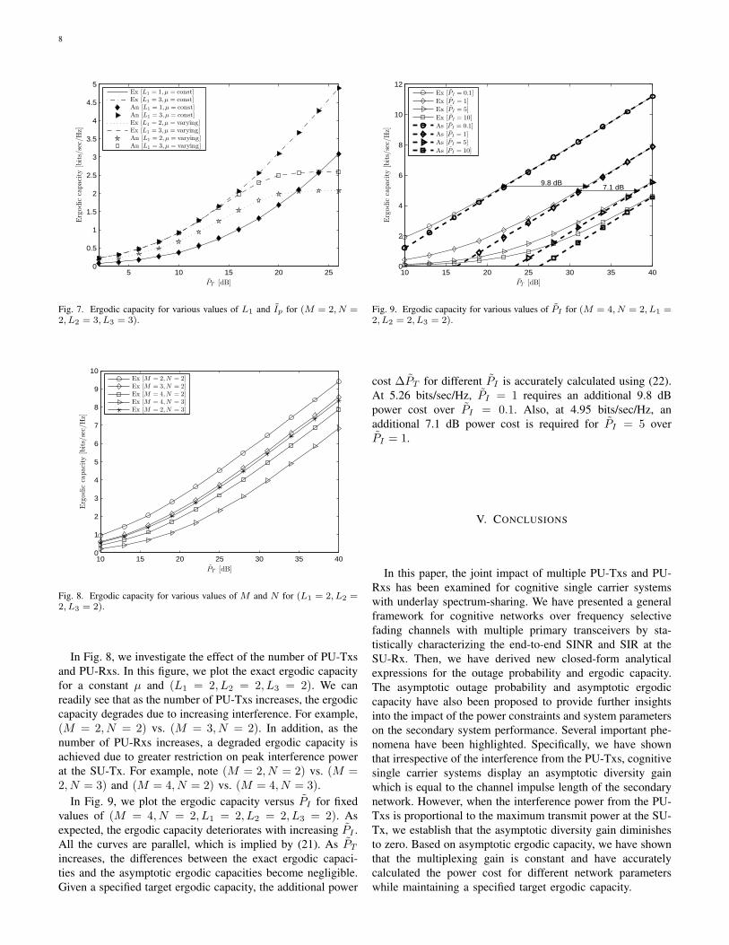
In Fig. 7, we show the exact and analytical ergodic ca-pacity for various values of L1 at fixed (M = 2, N =2, L2 = 3, L3 = 3). We consider two cases of PT : 1) PT
proportional to Ip, which is specified by µ = const; and2) PT is fixed and independent of Ip, which is specified byµ = varying. This figure shows that when µ is constant, theergodic capacity increases with increasing L1 due to a highermultipath gain. However, for a fixed value of PT = 10 dB, asIp increases, PT dominates min
(PT ,
Ip
maxk=1,...,N
αg,k∥gk∥2
),
since min(PT ,
Ip
maxk=1,...,N
αg,k∥gk∥2
)≈ PT . Thus, we ob-
serve that although a higher ergodic capacity is achieveddepending on the size of L1, it enters a saturation region fora fixed value of PT .
8
5 10 15 20 250
0.5
1
1.5
2
2.5
3
3.5
4
4.5
5
PT [dB]
Erg
odic
capaci
ty[b
its/
sec/
Hz]
Ex [L1 = 1, µ = const]Ex [L1 = 3, µ = const]An [L1 = 1, µ = const]An [L1 = 3, µ = const]Ex [L1 = 2, µ = varying]Ex [L1 = 3, µ = varying]An [L1 = 2, µ = varying]An [L1 = 3, µ = varying]
Fig. 7. Ergodic capacity for various values of L1 and Ip for (M = 2, N =2, L2 = 3, L3 = 3).
10 15 20 25 30 35 400
1
2
3
4
5
6
7
8
9
10
PT [dB]
Erg
odic
capaci
ty[b
its/
sec/
Hz]
Ex [M = 2,N = 2]Ex [M = 3,N = 2]Ex [M = 4,N = 2]Ex [M = 4,N = 3]Ex [M = 2,N = 3]
Fig. 8. Ergodic capacity for various values of M and N for (L1 = 2, L2 =2, L3 = 2).
In Fig. 8, we investigate the effect of the number of PU-Txsand PU-Rxs. In this figure, we plot the exact ergodic capacityfor a constant µ and (L1 = 2, L2 = 2, L3 = 2). We canreadily see that as the number of PU-Txs increases, the ergodiccapacity degrades due to increasing interference. For example,(M = 2, N = 2) vs. (M = 3, N = 2). In addition, as thenumber of PU-Rxs increases, a degraded ergodic capacity isachieved due to greater restriction on peak interference powerat the SU-Tx. For example, note (M = 2, N = 2) vs. (M =2, N = 3) and (M = 4, N = 2) vs. (M = 4, N = 3).
In Fig. 9, we plot the ergodic capacity versus PI for fixedvalues of (M = 4, N = 2, L1 = 2, L2 = 2, L3 = 2). Asexpected, the ergodic capacity deteriorates with increasing PI .All the curves are parallel, which is implied by (21). As PT
increases, the differences between the exact ergodic capaci-ties and the asymptotic ergodic capacities become negligible.Given a specified target ergodic capacity, the additional power
10 15 20 25 30 35 400
2
4
6
8
10
12
9.8 dB7.1 dB
PT [dB]
Ergodic
capacity
[bits/sec/Hz]
Ex [PI = 0.1]
Ex [PI = 1]
Ex [PI = 5]
Ex [PI = 10]
As [PI = 0.1]
As [PI = 1]
As [PI = 5]
As [PI = 10]
Fig. 9. Ergodic capacity for various values of PI for (M = 4, N = 2, L1 =2, L2 = 2, L3 = 2).
cost ∆PT for different PI is accurately calculated using (22).At 5.26 bits/sec/Hz, PI = 1 requires an additional 9.8 dBpower cost over PI = 0.1. Also, at 4.95 bits/sec/Hz, anadditional 7.1 dB power cost is required for PI = 5 overPI = 1.
V. CONCLUSIONS
In this paper, the joint impact of multiple PU-Txs and PU-Rxs has been examined for cognitive single carrier systemswith underlay spectrum-sharing. We have presented a generalframework for cognitive networks over frequency selectivefading channels with multiple primary transceivers by sta-tistically characterizing the end-to-end SINR and SIR at theSU-Rx. Then, we have derived new closed-form analyticalexpressions for the outage probability and ergodic capacity.The asymptotic outage probability and asymptotic ergodiccapacity have also been proposed to provide further insightsinto the impact of the power constraints and system parameterson the secondary system performance. Several important phe-nomena have been highlighted. Specifically, we have shownthat irrespective of the interference from the PU-Txs, cognitivesingle carrier systems display an asymptotic diversity gainwhich is equal to the channel impulse length of the secondarynetwork. However, when the interference power from the PU-Txs is proportional to the maximum transmit power at the SU-Tx, we establish that the asymptotic diversity gain diminishesto zero. Based on asymptotic ergodic capacity, we have shownthat the multiplexing gain is constant and have accuratelycalculated the power cost for different network parameterswhile maintaining a specified target ergodic capacity.

9
APPENDIX A: DERIVATION OF LEMMA 1
The PDF and the CDF of the gamma distributed RV A are,respectively, given by
fA(x) =βL1
h
Γ(L1)xL1−1e−βhxU(x) and
FA(x) =(1− e−βhx
L1−1∑i=0
(βhx)i
i!
)U(x). (A.1)
According to the derivations provided in [37], the PDF of theRV B
=∑M
k=1 PIk αf,k∥fk∥2 is given by
fB(x) =
M∑i=1
L2∑j=1
(−1)jθi,jΓ(j)
xj−1e− x
PIiαf,i U(x). (A.2)
Now using Eqs. (A.1) and (A.2), the CDF of the RV Y is
FY (y) =
∫ ∞
0
fB(x)FA(yx)dx
= 1−L1−1∑l=0
(βh)lyl
Γ(l + 1)
∫ ∞
0
fB(x)e−βhyx(x)ldx
= 1−L1−1∑l=0
(βh)lyl
Γ(l + 1)
M∑i=1
L2∑j=1
(−1)jθi,jΓ(j)∫ ∞
0
e−x(βhy+
1PIi
αf,i
)(x)l+j−1dx
= 1−L1−1∑l=0
M∑i=1
L2∑j=1
(−1)j(βh)−jθi,jΓ(l + j)
Γ(l + 1)Γ(j)
yl(y +
1
βhPIi αf,i
)−(l+j)
U(y) (A.3)
which proves (6).
APPENDIX B: DERIVATION OF (7)
For the final form of (4), we need to compute
I1(x) =∫ ∞
µ
FY (xt/Ip)fX(t)dt (B.1)
which is evaluated as
I1(x) = 1− FX(µ)−∑ L1−1∑
l=0
M∑i=1
L2∑j=1
Λi,j,l
[l(x/Ip
)−j
∫ ∞
µ
tl+l−1e−βgt(t+
Ip
βhPIi αf,ix
)−(l+j)
dt︸ ︷︷ ︸J1(x)
]+
∑ L1−1∑l=0
M∑i=1
L2∑j=1
Λi,j,l
[βg
(x/Ip
)−j
∫ ∞
µ
tl+le−βgt(t+
Ip
βhPIi αf,ix
)−(l+j)
dt︸ ︷︷ ︸J2(x)
]. (B.2)
With some computations, we can obtain J1(x) and J2(x).
APPENDIX C: A PROOF OF THEOREM 1
We start the derivation by rewriting the definition ofFY (x/PT ), which is given by
FY (x/PT ) = Pr(A < xB/PT
)= EB
FA
(xB/PT
∣∣B). (C.1)
For a frequency selective fading channel, FA(xB/PT |B) can
be approximated as FA
(xBPT
∣∣B) PT→∞≈ 1
Γ(L1+1)
(βhxB
PT
)L1
[12]; thus an asymptotic FY (x/PT ) is given by
FY (x/PT ) =M∑i=1
L2∑j=1
(−1)jθi,j(βh)L1Γ(L1 + j)(PIi αf,i)
L1+j
Γ(j)Γ(L1 + 1)
( xPT
)L1
= Ω1
( xPT
)L1. (C.2)
Using (C.2), an asymptotic I1(x) can be evaluated as
I1(x) =
∫ ∞
µ
FY
(xt/Ip
)fX(t)dt
= Ω1
(x/µPT
)L1
∫ ∞
µ
tL1fX(t)dt. (C.3)
Replacing fX(t) with the corresponding expression in (5), wehave
I1(x) =∫ ∞
µ
FY
(xt/Ip
)fX(t)dt
= Ω1
(1
µ
)L1 ∑[l(βg)
−(L1+l)Γ(L1 + l, µβg)−
βg(βg)−(L1+l+1)Γ(L1 + l + 1, µβg)
]( x
PT
)L1
. (C.4)
Now using (C.2) and (C.4), we can readily obtain the follow-ing:
Pout(γth) ≈PT →∞,
Ip→∞,µ=const
Ω1
(FX(µ) + (1/µ)
L1∑[
l(βg)−(L1+l)
Γ(L1 + l, µβg)− (βg)−(L1+l)
Γ(L1 + l + 1, µβg)])(
γth/PT
)L1
(C.5)
where Ω1=
M∑i=1
L2∑j=1
(−1)jθi,j(βh)L1Γ(L1 + j)(PIi αf,i)
L1+j
Γ(j)Γ(L1 + 1)
and Γ(·, ·) denotes the incomplete gamma function. Thus,it can be seen that the outage diversity gain as a functionof(γth/PT
)is given by Gd = L1. Similarly, the outage
probability at a fixed PT is given by
Pout(γth) ≈ Ω2µL1 +Ω2
∑[l(βg)
−(L1+l)Γ(L1 + l, µβg)−
(βg)−(L1+l)Γ(L1 + l + 1, µβg)
](C.6)
where Ω2=Ω1
(γth/Ip
). From the definition of the outage
diversity gain, (C.6) shows no outage diversity gain.
10
APPENDIX D: DERIVATION OF (14)
According to (8) and (12), we rewrite Υ2 as
Υ2 = e−βgµl+l−1∑p=0
(l + l − 1
p
)µl+l−1−p(Ip)
j~ (D.1)
where
~=
∫ ∞
0
x−j
1 + x
(µ+
Ip
βhPIi αf,ix
)p−j−l+1
∫ ∞
0
tpe−βg
(µ+
Ip
βhPIiαf,ix
)t(1 + t)
−(j+l)dtdx. (D.2)
Changing variables and the order of integration, ~ is trans-formed as
~ =
∫ ∞
0
tpe−βgt(µ+ t)−(j+l)
∫ ∞
0
xl
1 + x
(x+
Ip
βhPIi αf,i(µ+ t)
)−(j+l)
dxdt. (D.3)
From Υ2 in (12) and (13), the interior integral can be easilyevaluated by substituting Ip
βhPIiαf,i(µ+t)
for PT
βhPIiαf,i
. Hence,we derive (D.3) as (D.4) at the top of the following page. Toevaluate integral Ξ1 in (D.4), we use the following identity [38,pp. 152]:
(1 + dix)−υi =
1
Γ (υi)H1,1
1,1
[dix|(1−υi,1)
(0,1)
](D.5)
where HM,NA,B [·] denotes Fox’s H-function [39, Eq. 8.3.1.1].
Using (D.5) and [38, Eq. 2.6.2], we obtain Ξ1 as
Ξ1 =µ−l(βg)
−(p+1)
Γ(l)Γ(l + j − k)H1,1,1,1,1
1,(1:1),0,(1:1) (µβg)−1
βhPIiαf,i
(βhPIiαf,iµ−Ip)βg
∣∣∣∣∣∣∣(1 + p, 1)
(1− l, 1); (1− l − j + k, 1)−
(0, 1); (0, 1)
. (D.6)
By employing [38, Eq. 2.3.2], (D.6) can be simplified interms of the Kampe de Feriet’s function, which is reflectedin (D.9) at the top of the page after next. Using a partialfraction expansion [33, Eq. (2.102)], the identity in (D.5),
log (1 + z) = H1,02,2
[z
∣∣∣∣∣(1, 1), (1, 1)(1, 1), (0, 1)
][38, pp. 152], and [38,
Eq. 2.6.2], Ξ2 in (D.4) is obtained as (D.7) which is pro-vided on the next page. According to (D.4) and (D.6), wecan directly obtain Ξ3 in (D.4) as (D.8) on the next page.Substituting (D.6), (D.7), and (D.8) into (D.4), we obtain ~.Substituting ~ into (D.1), we arrive at ζ, which is expressedin (D.9). In (D.9), Fϖ:ϑ
ρ:σ [·] is the Kampe de Feriet function
[35] and HK,N,N′,M,M
′
E,(A:C),F,(B:D) [·] is the generalized Fox’s H-
function [38, Eq. (2.2.1)]. We also define ∆2,1=2l+j−k−υ1,
∆2,2=2l + j − k − υ2, and ∆1,2
=l + j − k − υ2.
APPENDIX E: DERIVATION OF (19)
Using integration by parts, (19) is given by
C∞ =1
log(2)
[log(PT ) + (1− FX(µ)) log(µ)−
FX(µ)
∫ ∞
0
fY (x) log(1/PT+x)dx︸ ︷︷ ︸Θ1
−
∫ ∞
0
log(1/Ip+x)
∫ ∞
µ
tfY (xt)fX(t)dtdx︸ ︷︷ ︸Θ2
](E.1)
where fY (x) is obtained through the derivative of FY (x); thatis, from (A.3), we obtain fY (x) as
fY (x) =
L1−1∑l=1
(βh)llxl−1
Γ(l + 1)
M∑i=1
L2∑j=1
(−1)jθi,j
Γ(j)∫ ∞
0
e−t
(βhx+
1PIi
αf,i
)(t)l+j−1dt−
L1−1∑l=0
(βh)l+1
xl
Γ(l + 1)
M∑i=1
L2∑j=1
(−1)jθi,j
Γ(j)∫ ∞
0
e−t
(βhx+
1PIi
αf,i
)(t)l+jdt. (E.2)
As PT → ∞, Θ1 becomes asymptotically
Θ1 =
∫ ∞
0
fY (x) log(x)dx. (E.3)
Substituting (E.2) into (E.3) and changing the orderof integration, after some algebraic manipulations,we obtain (E.4) on the page after next. In (E.4),∫∞0xν−1e−µx log(x)dx = 1
µν Γ (ν) [ψ (ν)− lnµ] [33, Eq.4.352.1] is employed in the derivation of Θ1. Likewise, Θ2
is given asymptotically by
Θ2 =
∫ ∞
0
log(x)
∫ ∞
µ
tfY (xt)fX(t)dtdx. (E.5)
Changing the order of integration, we compute the integral in(E.5) as
Θ2 =
∫ ∞
µ
tfX(t)
∫ ∞
0
fY (xt) log(x)dxdt
=
∫ ∞
µ
fX(t)[∫ ∞
0
fY (x) log(xt
)dx]dt
=
∫ ∞
µ
fX(t)[∫ ∞
0
fY (x) log(x)dx+ log(t)]dt
=
∫ ∞
µ
fX(t) (Θ1 + log t) dt
= Θ1 (1− FX (µ)) +
∫ ∞
µ
fX(t) log(t)dt︸ ︷︷ ︸Λ
. (E.6)
Now we need to compute Λ as (E.7) on the page afternext. Using the binomial expansion and [33, Eq. 4.337.5], we

11
~ =l∑
k=0
(l
k
)(βhPIi αf,i
)j[(−Ip)
l−k(Ip − βhPIi αf,iµ)
−(l+j−k)
(log(Ip/βhPIi αf,iµ)
∫ ∞
0
tpe−βgt(µ+ t)−l(1 +
βhPIi αf,i
βhPIi αf,iµ− Ipt)−(l+j−k)
dt︸ ︷︷ ︸Ξ1
−∫ ∞
0
tpe−βgt(µ+ t)−l(1 +
βhPIi αf,i
βhPIi αf,iµ− Ipt)−(l+j−k)
log(1 + t/µ
)dt︸ ︷︷ ︸
Ξ2
)
−l+j−k∑τ=2
(−1)l−k
τ − 1(Ip)
l−k−(τ−1)(Ip − βhPIi αf,iµ)
−(l+j−k−τ+1)
∫ ∞
0
tpe−βgt(µ+ t)−l(1 +
βhPIi αf,i
βhPIi αf,iµ− Ipt)−(l+j−k−τ+1)
dt︸ ︷︷ ︸Ξ3
]. (D.4)
Ξ2 =
l∑υ1=1
(∆2,1 − 1
l − υ1
)(− βhPIi αf,i
βhPIi αf,iµ− Ip
)l−υ1(1− βhPIi αf,iµ
βhPIi αf,iµ− Ip
)−∆2,1 µ−υ1
Γ(υ1)(βg)
−(p+1)
H1,0,1,1,11,(2:1),0,(2:1)
(µβg)−1
(µβg)−1
∣∣∣∣∣∣∣(1 + p, 1)
(1, 1), (1, 1); (1− υ1, 1)−
(1, 1), (0, 1); (0, 1)
+
l+j−k∑υ2=1
(∆2,2 − 1
l − 1
)(−1)l+j−k−υ2
( Ip
βhPIi αf,i
)−∆2,2 (βg)−(p+1)
Γ(υ2)H1,0,1,1,1
1,(2:1),0,(2:1)
(µβg)−1
βhPIiαf,i
(βhPIiαf,iµ−Ip)βg
∣∣∣∣∣∣∣(1 + p, 1)
(1, 1), (1, 1); (1− υ2, 1)−
(1, 1), (0, 1); (0, 1)
. (D.7)
Ξ3 =µ−l(βg)
−(p+1)
Γ (l) Γ(l + j − k − τ + 1)H1,1,1,1,1
1,(1:1),0,(1:1)
(µβg)−1
βhPIiαf,i
(βhPIiαf,iµ−Ip)βg
∣∣∣∣∣∣∣(1 + p, 1)
(1− l, 1); (k + τ − l − j, 1)−
(0, 1); (0, 1)
. (D.8)
calculate Λ1 as
Λ1 =l−1∑i=0
(l − 1
i
)µl−1−i
[Γ(i+ 1)
(βg)i+1log(µ)+
(βg)−i−1
∫ ∞
0
tie−t log( t
µβg+ 1)dt]
(E.8)
which is equivalent to the following expression:
Λ1 =l−1∑i=0
(l − 1
i
)µl−1−i
(βg)i+1
[Γ(i+ 1) log(µ)+
i∑j=0
Γ(i+ 1)
Γ(i− j + 1)
((−1)i−j−1(µβg)
i−jeµβgEi(−µβg)+
i−j∑k=1
Γ(k)(−µβg)i−j−k)]. (E.9)
Similarly, we can obtain Λ2 as
Λ2 =
l∑i=0
(l
i
)µl−i
(βg)i+1
[Γ (i+1) log(µ)+
i∑j=0
Γ(i+ 1)
Γ(i− j + 1)
((−1)i−j−1(µβg)
i−jeµβgEi(−µβg)+
i−j∑k=1
Γ(k)(−µβg)i−j−k)]. (E.10)
Substituting (E.7) into (E.6), we have
Θ2 = Θ1 (1− FX (µ)) +∑
e−βgµ(lΛ1 − βgΛ2
). (E.11)
Thus, combining (E.11) and (E.1), we obtain (19).

12
ζ = (−Ip)l−k(Ip − βhPIi αf,iµ)−(l+j−k)
log( Ip
βhPIi αf,iµ
)µ−l(βg)
−(p+1)Γ (1 + p)
F1:10:0
[1 + p : l ; l + j − k ;− : − ;− ;
−(µβg
)−1,− βhPIi αf,i(
βhPIi αf,iµ− Ip)βg
]−
l∑υ1=1
(∆2,1 − 1
l − υ1
)(− βhPIi αf,i
βhPIi αf,iµ− Ip
)l−υ1(1− βhPIi αf,iµ
βhPIi αf,iµ− Ip
)−(∆2,1) µ−υ1
Γ (υ1)(βg)
−(p+1)
H1,0,1,1,11,(2:1),0,(2:1)
(µβg)−1
(µβg)−1
∣∣∣∣∣∣∣(1 + p, 1)
(1, 1), (1, 1); (1− υ1, 1)−
(1, 1), (0, 1); (0, 1)
−l+j−k∑υ2=1
(∆2,2 − 1
l − 1
)(−1)
∆1,2
(Ip
βhPIiαf,i
)−(∆2,2)
(βg)−(p+1)
Γ (υ2)H1,0,1,1,1
1,(2:1),0,(2:1)
(µβg)−1
βhPIiαf,i
(βhPIiαf,iµ−Ip)βg
∣∣∣∣∣∣∣(1 + p, 1)
(1, 1), (1, 1); (1− υ2, 1)−
(1, 1), (0, 1); (0, 1)
−l+j−k∑τ=2
(−1)l−k
τ − 1(Ip)
l−k−(τ−1)(Ip − βhPIi αf,iµ)−(l+j−k−τ+1)
µ−l(βg)−(p+1)
Γ (1 + p)
F1:10:0
[1 + p : l ; l + j − k − τ + 1 ;− : − ;− ;
−(µβg
)−1,− βhPIi αf,i
(βhPIi αf,iµ− Ip)βg
]. (D.9)
Θ1 =
L1−1∑l=1
(βh)ll
Γ(l + 1)
M∑i=1
L2∑j=1
(−1)jθi,j
Γ(j)
∫ ∞
0
e− t
PIiαf,i (t)
l+j−1∫ ∞
0
e−tβhxxl−1 log(x)dxdt−
L1−1∑l=0
(βh)l+1
Γ(l + 1)
M∑i=1
L2∑j=1
(−1)jθi,j
Γ(j)
∫ ∞
0
e− t
PIiαf,i (t)l+j
∫ ∞
0
e−tβhxxl log(x)dxdt
=
L1−1∑l=1
M∑i=1
L2∑j=1
(−1)jθi,j lΓ(l)(PIi αf,i)j
Γ(l + 1)
[ψ(l)− log(βh)− ψ(j)− log(PIi αf,i)
]−
L1−1∑l=0
M∑i=1
L2∑j=1
(−1)jθi,j(PIi αf,i)j[ψ (l + 1)− log(βh)− ψ(j)− log(PIi αf,i)
]. (E.4)
Λ =∑[
l
∫ ∞
µ
tl−1e−βgt log(t)dt− βg
∫ ∞
µ
tle−βgt log(t)dt]
=∑
e−βgµ[l
∫ ∞
0
(t+ µ)l−1
e−βgt(log(t
µ+ 1) + log(µ))dt︸ ︷︷ ︸
Λ1
− βg
∫ ∞
0
(t+ µ)le−βgt(log(
t
µ+ 1) + log(µ))dt︸ ︷︷ ︸
Λ2
]. (E.7)

13
REFERENCES
[1] D. Chen, S. Yin, Q. Zhang, M. Liu, and S. Li, “Mining spectrum usagedata: A large-scale spectrum measurement study,” in Proc. ACM Int.Conf. on Mobile Computing and Networking, Beijing, China, Sep. 2009,pp. 13–24.
[2] M. Wellens, J. Wu, and P. Mahonen, “Evaluation of spectrum occupancyin indoor and outdoor scenario in the context of cognitive radio,” in Proc.Int. Conf. on Cognitive Radio Oriented Wireless Networks, Orlando, FL,Jul. 2007, pp. 420–427.
[3] M. Lopez-Benitez, A. Umbert, and F. Casadevall, “Evaluation of spec-trum occupancy in Spain for cognitive radio applications,” in Proc. IEEEVeh. Techno. Conf. Spring, Barcelona, Spain, Apr. 2009, pp. 1–5.
[4] K. A. Qaraqe, H. Celebi, A. Gorcin, A. El-Saigh, H. Arslan, and M.-S. Alouini, “Empirical results for wideband multidimensional spectrumusage,” in Proc. IEEE Int. Symp. on Personal, Indoor and Mobile RadioCommun., Tokyo, Japan, Sep. 2009, pp. 1262–1266.
[5] M. H. Islam, C. L. Koh, S. W. Oh, X. Qing, Y. Y. Lai, C. Wang, Y.-C.Liang, B. E. Toh, F. Chin, G. L. Tan, and W. Toh, “Spectrum survey inSingapore: Occupancy measurements and analyses,” in Proc. Int. Conf.on Cognitive Radio Oriented Wireless Networks, Singapore, May 2008,pp. 1–7.
[6] M. A. McHenry, “NSF spectrum occupancy measurements projectsummary,” Shared Spectrum Co., Tech. Rep., Aug. 2005.
[7] V. N. Q. Bao, L. Q. Cuong, L. Q. Phu, T. D. Thuan, L. M. Trung, andN. T. Quy, “Spectrum survey in Vietnam: Occupancy measurements andanalysis for cognitive radio applications,” in Proc. Advanced Techno. forCommun., Da Nang, Vietnam, Aug. 2011, pp. 135–143.
[8] J. Mitola and G. Q. Maguire, Jr., “Cognitive radio: making softwareradio more personal,” IEEE Pers. Commun., vol. 6, no. 4, pp. 13–18,Aug. 1999.
[9] E. Biglieri, A. Goldsmith, L. J. Greenstein, N. B. Mandayam, and H. V.Poor, Principles of Cognitive Radio. Cambridge, UK: CambridgeUniversity Press, 2013.
[10] A. Ghasemi and E. S. Sousa, “Fundamental limits of spectrum-sharingin fading environments,” IEEE Trans. Wireless Commun., vol. 6, no. 2,pp. 649–658, Feb. 2007.
[11] H. A. Suraweera, P. J. Smith, and M. Shafi, “Capacity limits and perfor-mance analysis of cognitive radio with imperfect channel knowledge,”IEEE Trans. Veh. Technol., vol. 59, no. 4, pp. 1811–1822, May 2010.
[12] C. Zhong, T. Ratnarajah, and K.-K. Wong, “Outage analysis of decode-and-forward cognitive dual-hop systems with the interference constraintin Nakagami-m fading channels,” IEEE Trans. Veh. Technol., vol. 60,pp. 2875–2879, Jul. 2011.
[13] T. W. Ban, W. Choi, B. C. Jung, and D. K. Sung, “Multi-user diversityin a spectrum sharing system,” IEEE Trans. Wireless Commun., vol. 8,no. 1, pp. 102–106, Jan. 2009.
[14] K. J. Kim, T. Q. Duong, H. V. Poor, and L. Shu, “Performance analysisof cyclic prefixed single-carrier spectrum sharing relay systems inprimary user interference,” IEEE Trans. Signal Process., vol. 60, no. 12,pp. 6729–6734, Dec. 2012.
[15] K. J. Kim, T. Q. Duong, and X.-N. Tran, “Performance analysis ofcognitive spectrum-sharing single-carrier systems with relay selection,”IEEE Trans. Signal Process., vol. 60, no. 12, pp. 6435–6449, Dec. 2012.
[16] K. J. Kim, T. Q. Duong, and H. V. Poor, “Outage probability of single-carrier cooperative spectrum sharing systems with decode-and-forwardrelaying and selection combining,” IEEE Trans. Wireless Commun.,vol. 12, no. 2, pp. 806–817, Feb. 2013.
[17] N. Al-Dhahir, “Single carrier frequency domain equalization for spacetime block-coded transmissions over frequency-selective fading chan-nels,” IEEE Commun. Lett., vol. 7, no. 11, pp. 304–306, Jul. 2001.
[18] H. Mheidat, M. Uysal, and N. Al-Dhahir, “Equalization techniques fordistributed space-time block codes with amplify-and-forward relaying,”IEEE Trans. Signal Process., vol. 55, no. 5, pp. 1839–1852, May 2007.
[19] D.-Y. Seol, U.-K. Kwon, G.-H. Im, and E.-S. Kim, “Relay-based singlecarrier transmission with SFBC in uplink fast fading channels,” IEEECommun. Lett., vol. 12, no. 12, pp. 928–930, Dec. 2007.
[20] K. J. Kim, Y. Li, and T. A. Tsiftsis, “On the performance of cyclic-prefixed single-carrier cellular systems in cochannel interference,” IEEETrans. Veh. Technol., vol. 60, no. 8, pp. 4035–4040, Oct. 2011.
[21] T. Q. Duong, P. L. Yeoh, V. N. Q. Bao, M. Elkashlan, and N. Yang,“Cognitive relay networks with multiple primary transceivers underspectrum-sharing,” IEEE Signal Process. Lett., vol. 19, no. 11, pp. 741–744, Nov. 2012.
[22] K. J. Kim, T. Q. Duong, M. Elkashlan, P. L. Yeoh, H. V. Poor, andM. H. Lee, “Spectrum sharing single-carrier in the presence of multiplelicensed receivers,” IEEE Trans. Wireless Commun., vol. 12, no. 10, pp.5223–5235, Oct. 2013.
[23] Y. Zou, J. Zhu, B. Zheng, and Y.-D. Yao, “An adaptive cooperatingdiversity scheme with best-relay selection in cognitive radio networks,”IEEE Trans. Signal Process., vol. 58, no. 10, pp. 5438–5445, Oct. 2010.
[24] J. Lee, H. Wang, J. G. Andrews, and D. Hong, “Outage probabilityof cognitive relay networks with interference constraints,” IEEE Trans.Wireless Commun., vol. 10, no. 2, pp. 390–395, Feb. 2011.
[25] H. Ding, J. Ge, D. da Costa, and Z. Jiang, “Asymptotic analysis ofcooperative diversity systems with relay selection in a spectrum-sharingscenario,” IEEE Trans. Veh. Technol., vol. 60, no. 2, pp. 457–472, Feb.2011.
[26] H. Yu, I.-H. Lee, and G. L. Stuber, “Outage probability of decode-and-forward cooperative relaying systems with co-channel interference,”IEEE Trans. Wireless Commun., vol. 11, no. 1, pp. 266–274, Jan. 2011.
[27] P. A. Dmochowski, H. A. Suraweera, P. J. Smith, and M. Shafi, “Impactof channel knowledge on cognitive radio system capacity,” in Proc. IEEEVeh. Technol. Conf. (VTC 2010 Fall), Ottawa, Canada, Sep. 2010, pp.1–5.
[28] S. Kato, H. Harada, R. Funada, T. Baykas, C. S. Sum, J. Wang, andM. A. Rahman, “Single carrier transmission for multi-gigabit 60-GHzWPAN systems,” IEEE J. Sel. Areas Commun., vol. 27, no. 8, pp. 1466–1478, Oct. 2009.
[29] T.-H. Pham, Y.-C. Liang, A. Nallanathan, and H. Garg, “Optimal trainingsequences for channel estimation in bi-directional relay networks withmultiple antennas,” IEEE Trans. Commun., vol. 58, no. 2, pp. 474–479,Feb. 2010.
[30] P. R. Davis, Circulant Matrices. New York: John Wiley, 1979.[31] K. J. Kim, T. A. Tsiftsis, and H. V. Poor, “Power allocation in
cyclic prefixed single-carrier relaying systems,” IEEE Trans. WirelessCommun., vol. 10, no. 7, pp. 2297–2305, Jul. 2011.
[32] T. Zhang, Y. Cai, and W. Yang, “Performance analysis of multi-sourcemulti-relay wireless networks with co-channel interference,” Electron.Lett., vol. 49, no. 4, pp. 304–305, Feb. 2013.
[33] I. S. Gradshteyn and I. M. Ryzhik, Table of Integrals, Series, andProducts. New York: Academic Press, 2007.
[34] H. A. Suraweera, D. S. Michalopoulos, and C. Yuen, “Performanceanalysis of fixed gain relay systems with a single interferer in Nakagami-m fading channels,” IEEE Trans. Veh. Technol., vol. 61, no. 3, pp. 102–106, Mar. 2012.
[35] H. Shin and J. B. Song, “MRC analysis of cooperative diversity withfixed-gain relays in Nakagami-m fading channels,” IEEE Trans. WirelessCommun., vol. 7, pp. 2069–2074, Jun. 2008.
[36] A. Lozano, A. M. Tulino, and S. Verdu, “High-SNR power offset inmultiantenna communication,” in Proc. IEEE Int. Symp. Inf. Theory,Chicago, IL, Jun. 2004, p. 287.
[37] X. W. Cui, Q. T. Zhang, and Z. M. Feng, “Outage performance formaximal ratio combiner in the presence of unequal-power co-channelinterferers,” IEEE Commun. Lett., vol. 8, no. 5, pp. 289–291, May 2004.
[38] A. M. Mathai and R. K. Saxena, The H-function with Applications inStatistics and Other Disciplines. New York: Wiley, 1978.
[39] A. P. Prudnikov, Y. A. Brychkov, , and O. I. Marichev, Integrals andSeries. New York: Gordon and Breach Science, 1990.

14
Kyeong Jin Kim (SM’11) received the M.S. degreefrom the Korea Advanced Institute of Science andTechnology (KAIST) in 1991 and the M.S. andPh.D. degrees in electrical and computer engineeringfrom the University of California, Santa Barbara in2000. During 1991-1995, he was a research engineerat the video research center of Daewoo Electronics,Ltd., Korea. In 1997, he joined the data transmissionand networking laboratory, University of California,Santa Barbara. After receiving his degrees, he joinedthe Nokia research center (NRC) and Nokia Inc.,
Dallas, TX, as a senior research engineer, where he was, from 2005 to 2009,an L1 specialist. During 2010-2011, he was an Invited Professor at InhaUniversity, Korea. Since 2012, he has worked as a senior principal researchstaff member in the Mitsubishi Electric Research Laboratories (MERL), Cam-bridge, MA. His research has been focused on the transceiver design, resourcemanagement, scheduling in the cooperative wireless communications systems,cooperative spectrum sharing system, and device-to-device communications.
Dr. Kim currently serves as an editor for the IEEE COMMUNICATIONSLETTERS. He also serves as guest editors for the EURASIP JOURNALON WIRELESS COMMUNICATIONS AND NETWORKING: Special Issue on”Cooperative Cognitive Networks” and IET COMMUNICATIONS: SpecialIssue on ”Secure Physical Layer Communications”. He served as a TPCchair for the IEEE GLOBECOM 2013 and 2014 Workshop on TrustedCommunications with Physical Layer Security.
Lifeng Wang (S’12) is working towards his Ph.D.degree in Electronic Engineering at Queen MaryUniversity of London. Before that, he received theM.S. degree in Electronic Engineering from theUniversity of Electronic Science and Technologyof China, in 2012. His research interests includeMIMO, cooperative communications, cognitive ra-dio, and physical layer security.
Trung Q. Duong (S’05, M’12, SM’13) received hisPh.D. degree in Telecommunications Systems fromBlekinge Institute of Technology (BTH), Swedenin 2012, and then continued working at BTH as aproject manager. Since 2013, he has joined Queen’sUniversity Belfast, UK as a Lecturer (AssistantProfessor). He held a visiting position at PolytechnicInstitute of New York University and SingaporeUniversity of Technology and Design in 2009 and2011, respectively. His current research interestsinclude cooperative communications, cognitive radio
networks, physical layer security, massive MIMO, cross-layer design, mm-waves communications, and localization for radios and networks.
Dr. Duong has been a TPC chair for several IEEE international conferencesand workshops including the most recently IEEE GLOBECOM13 Workshopon Trusted Communications with Physical Layer Security. He currentlyserves as an Editor for the IEEE COMMUNICATIONS LETTERS, WILEYTRANSACTIONS ON EMERGING TELECOMMUNICATIONS TECHNOLOGIES.Dr. Duong has served as the Lead Guest Editor of the special issue on“Location Awareness for Radios and Networks” of the IEEE JOURNALIN SELECTED AREAS ON COMMUNICATIONS, the Lead Guest Editor ofthe special issue on “Secure Physical Layer Communications” of the IETCOMMUNICATIONS, Guest Editor of the special issue on “Green Media:Toward Bringing the Gap between Wireless and Visual Networks” of theIEEE WIRELESS COMMUNICATIONS MAGAZINE, Guest Editor of the specialissue on “Millimeter Wave Communications for 5G” and “Energy HarvestingCommunications” of the IEEE COMMUNICATIONS MAGAZINE, Guest Editorof the special issue on “Cooperative Cognitive Networks” of the EURASIPJOURNAL ON WIRELESS COMMUNICATIONS AND NETWORKING, GuestEditor of special issue on “Security Challenges and Issues in Cognitive RadioNetworks” of the EURASIP JOURNAL ON ADVANCES SIGNAL PROCESS-ING. He is awarded the Best Paper Award at the IEEE Vehicular TechnologyConference (VTC-Spring) in 2013 and the Exemplary Reviewer Certificate ofthe IEEE Communications Letters in 2012.
Maged Elkashlan (M’06) received the Ph.D. de-gree in Electrical Engineering from the Universityof British Columbia, Canada, 2006. From 2006 to2007, he was with the Laboratory for AdvancedNetworking at University of British Columbia. From2007 to 2011, he was with the Wireless andNetworking Technologies Laboratory at Common-wealth Scientific and Industrial Research Organiza-tion (CSIRO), Australia. During this time, he heldan adjunct appointment at University of TechnologySydney, Australia. In 2011, he joined the School
of Electronic Engineering and Computer Science at Queen Mary Universityof London, UK, as an Assistant Professor. He also holds visiting facultyappointments at the University of New South Wales, Australia, and BeijingUniversity of Posts and Telecommunications, China. His research interests fallinto the broad areas of communication theory, wireless communications, andstatistical signal processing for distributed data processing, millimeter wavecommunications, cognitive radio, and wireless security.
Dr. Elkashlan currently serves as an Editor of the IEEE TRANSACTIONS ONWIRELESS COMMUNICATIONS, the IEEE TRANSACTIONS ON VEHICULARTECHNOLOGY, and the IEEE COMMUNICATIONS LETTERS. He also servesas the Lead Guest Editor for the special issue on “Green Media: The Future ofWireless Multimedia Networks” of the IEEE WIRELESS COMMUNICATIONSMAGAZINE, Lead Guest Editor for the special issue on “Millimeter WaveCommunications for 5G” of the IEEE COMMUNICATIONS MAGAZINE, GuestEditor for the special issue on “Energy Harvesting Communications” of theIEEE COMMUNICATIONS MAGAZINE, and Guest Editor for the special issueon “Location Awareness for Radios and Networks” of the IEEE JOURNALON SELECTED AREAS IN COMMUNICATIONS. He received the Best PaperAward at the IEEE Vehicular Technology Conference (VTC-Spring) in 2013.He received the Exemplary Reviewer Certificate of the IEEE CommunicationsLetters in 2012.
H. Vincent Poor (S’72, M’77, SM’82, F’87) re-ceived the Ph.D. degree in EECS from PrincetonUniversity in 1977. From 1977 until 1990, he wason the faculty of the University of Illinois at Urbana-Champaign. Since 1990 he has been on the facultyat Princeton, where he is the Michael Henry StraterUniversity Professor of Electrical Engineering andDean of the School of Engineering and AppliedScience. Dr. Poor’s research interests are in the areasof information theory, statistical signal processingand stochastic analysis, and their applications in
wireless networks and related fields including social networks and smart grid.Among his publications in these areas are the recent books Principles ofCognitive Radio (Cambridge University Press, 2013) and Mechanisms andGames for Dynamic Spectrum Allocation (Cambridge University Press, 2014).
Dr. Poor is a member of the National Academy of Engineering and theNational Academy of Sciences, and a foreign member of Academia Europaeaand the Royal Society. He is also a fellow of the American Academy ofArts and Sciences, the Royal Academy of Engineering (U.K.), and the RoyalSociety of Edinburgh. He received the Marconi and Armstrong Awards ofthe IEEE Communications Society in 2007 and 2009, respectively. Recentrecognition of his work includes the 2011 IEEE Eric E. Sumner Award,the 2014 URSI Booker Gold Medal, and honorary doctorates from AalborgUniversity, the Hong Kong University of Science and Technology, and theUniversity of Edinburgh.