coherent imaging of a pure phase object with classical incoherent
TRANSCRIPT
Coherent imaging of a pure phase object with classical incoherent light
M. Bache,* D. Magatti, F. Ferri, A. Gatti, E. Brambilla, and L. A. LugiatoCNR-INFM-CNISM, Dipartimento di Fisica e Matematica, Università dell’Insubria, Via Valleggio 11, 22100 Como, Italy
�Received 21 December 2005; published 3 May 2006�
By using the ghost imaging technique, we experimentally demonstrate the reconstruction of the diffractionpattern of a pure phase object by using the classical correlation of incoherent thermal light split on a beamsplitter. The results once again underline that entanglement is not a necessary feature of ghost imaging. Thelight we use is spatially highly incoherent with respect to the object ��2 �m speckle size� and is produced bya pseudo-thermal source relying on the principle of near-field scattering. We show that in these conditions noinformation on the phase object can be retrieved by only measuring the light that passed through it, neither ina direct measurement nor in a Hanbury Brown-Twiss �HBT� scheme. In general, we show a remarkablecomplementarity between ghost imaging and the HBT scheme when dealing with a phase object.
DOI: 10.1103/PhysRevA.73.053802 PACS number�s�: 42.50.Dv, 42.50.Ar, 42.30.Va
I. INTRODUCTION
Ghost imaging is a technique which allows one to per-form coherent imaging with incoherent light by exploitingthe spatial correlation between two beams created by, e.g.,parametric down conversion �PDC� �1–20�. Each of the cor-related beams is sent through a distinct imaging system, tra-ditionally called the test and the reference arm. In the testarm an object is placed and information about the object isrecreated from the spatial correlation function between thetest and reference arm.
One of the most striking features of the ghost imagingtechnique is that since the two beams are spatially incoherentno phase-sensitive information about an object can be ex-tracted by observing a single beam only. This means that thediffraction pattern of an object that substantially alters thephase of the incoming light cannot be observed in any way inthe test arm. Nonetheless, because of the mutual spatial cor-relation between the two beams, we will show that the dif-fraction pattern may be reconstructed through the spatial cor-relation between the two beams. In other words, despite thebeams being incoherent, the coherence between them makesthe imaging coherent: the scheme is therefore capable of do-ing coherent imaging with incoherent light.
On the other hand, the diffraction pattern of an object thatonly alters the amplitude of the light, such as a Young’sdouble slit, can be extracted from the intensity distribution ofthe object arm only, even when the object is illuminated witha spatially incoherent beam. One may do so by measuringthe autocorrelation of the transmitted field as observed in thefar zone of the object. This can be conveniently done byusing the Hanbury Brown-Twiss �HBT� scheme �21�. Thus,the ghost imaging technique is not required in this case, andone may stick to using a single beam only.
It is therefore interesting to look beyond the case of anamplitude-only object. As an extreme case, in this work we
want to observe the diffraction pattern of a pure phase ob-ject, an object that only alters phase information �9,13,15�.
Initially the possibility of performing ghost imaging wasascribed to the presence of spatial entanglement between thetwo arms �3–5,8�. Lately this view has been challenged bymany groups �10,12,13,17–20,22–28� �to cite but a few�. Ourgroup in particular has produced numerous publications,showing both theoretically �13� and experimentally �23–25�that basically all features offered by entangled ghost imagingcan be mimicked by using a proper scheme that exploitsclassically correlated beams: the correlation between thebeams is in this scheme created by dividing an incoherentpseudo-thermal speckle beam on a beam splitter �BS�. Thetwo outgoing beams are then still incoherent on their ownbut, since they are �classical� copies of each other, they havea high mutual spatial coherence. We showed that the onlyfeature that cannot be mimicked by classical correlation isthe 100% visibility of the information, which can be in prin-ciple achieved only with entangled photons; however, in theclassical case the visibility is still good enough to effectivelyreconstruct the information �13,17–20,23–25�. An importantoutcome of our analyses is that the entangled ghost imagingand our classical ghost imaging have the common feature ofproviding coherent imaging using incoherent light �13�.Thus, both schemes should be able to reconstruct the diffrac-tion pattern of any object, altering amplitude as well as phase�13�. We experimentally confirmed this prediction in the caseof an amplitude object �23�.
An experiment of Abouraddy et al. �9� demonstrated thereconstruction of the ghost diffraction pattern of a pure phaseobject using the entangled photon pairs produced by sponta-neous parametric down conversion, which represents an op-tical field that lacks second-order spatial coherence but isendowed with higher order spatial coherence. The introduc-tion of Ref. �9� claims that our ghost diffraction experimentwith classical thermal light reported in Ref. �23� could beperformed only because effectively the thermal light was en-dowed with second-order spatial coherence. This might sug-gest that coherent imaging with spatially incoherent light isnot possible with split thermal light. This interpretation ofour experiment �23� was not correct, because the light we
*Present address: COM·DTU, Technical University of Denmark,DK-2800 Lyngby, Denmark.
PHYSICAL REVIEW A 73, 053802 �2006�
1050-2947/2006/73�5�/053802�12� ©2006 The American Physical Society053802-1

used there was indeed spatially incoherent to a high degree.The viewpoint of Ref. �9� was challenged in Refs. �24,25�,where not only did we experimentally demonstrated againthe ghost diffraction of an amplitude object with classicalincoherent light, but also showed that the spatial incoherenceof the light is a necessary ingredient to carry out the task. Inthis work we will finally demonstrate experimentally andtheoretically that the claim of Ref. �9� is not correct also inthe case of a pure phase object.
We will show that the diffraction pattern of a commonlyused pure phase object, a transmission grating beam splitter�TGBS�, can be reconstructed from the classical correlationsbetween two highly spatially incoherent beams generated bysplitting a speckle beam on a BS. In order to render the lightimpinging on the object incoherent with respect to the object,we have to produce speckles of size on the order of 2.0 �m,and we achieve it through the so-called near-field scatteringtechnique �29,30�. Incidentally we remark that such a smallspeckle size, which implies a spatial resolution on the orderof 2.0 �m �see, e.g., Ref. �23��, has no precedent to ourknowledge in ghost imaging schemes, either with thermal orentangled beams.
With such a degree of spatial incoherence, we will verifythat no information about the phase object diffraction patternis present in the test arm, neither in the far zone intensitydistribution nor in its autocorrelation, which is equivalent toa HBT type of measurement. The information gradually ap-pears in the test arm as the degree of spatial coherence in-creases. The converse holds for the ghost diffraction scheme:the information on the phase object can be retrieved from thecorrelation between the test and the reference arm only whenthe light is spatially incoherent, and it disappears when in-creasing the coherence. From these results we will concludethat the claim of Ref. �9� is incorrect for the ghost imagingscheme, which indeed works as a coherent imaging schemeonly because of incoherence. This claim could be possiblyapplied to the HBT scheme, which in the case of a phaseobject works as a coherent imaging system only when thelight is coherent.
Thus, there exist remarkable differences between theghost imaging and the HBT schemes, which will be clarifiedin the present work.
The paper is organized as follows. Section II describes theexperimental setup. Section III is devoted to theoretical re-sults, with Sec. III A giving the basics of the theory of theghost diffraction, Sec. III B discussing the properties of thechosen object, and Sec. III C presenting some numerical re-sults used as a guideline for the experimental implementa-tion. In fact, the speckles needed are so small that we have touse a near-field scattering technique to produce them. Thistechnique, along with its experimental implementation, is de-scribed in Sec. IV A. Section IV B finally presents the ex-perimental results of ghost diffraction and of the HBTscheme with incoherent illumination, while Sec. IV Cpresent results illustrating the transition from incoherent tocoherent illumination. Section V concludes the work.
II. THE SETUP
The ghost diffraction setup used in our experiment isschematically shown in Fig. 1. A pseudo-thermal source gen-
erates a chaotic speckle beam, which enters a balanced50/50 BS �the side of the glass cube is 12.5 mm�. Thepseudo-thermal source �Fig. 1�a�� consists of a large colli-mated laser beam �frequency doubled Nd:YAG laser,�=0.532 �m, diameter D�10 mm� illuminating a slowlyrotating ground glass followed by a square cell containing acolloidal turbid solution. The transversal size of the source isdelimited by a pinhole of diameter Dph=4.5 mm, which isplaced at the exit face of the turbid cell. A detailed descrip-tion of the thermal source together with the features of thespeckles that it generates will be given in Sec. IV A.
The BS divides the pseudo-thermal radiation into two“twin” speckle beams: the transmitted one is used for the testarm and is sent onto the object located right after the BS at adistance z=18 mm from the source. The reflected beam isused for the reference arm; the mirror M deflects it towardsthe detector in a direction forming a small angle with the testarm. Note that, thanks to the double reflection of the refer-ence arm, the test and reference beams on the detector arenot mutually reversed, but are each other’s replica.
Both beams are collected by the central part of the lens F�focal length F=50 mm� and their intensity distributions aredetected by a charged coupled device �CCD� sensor placedin the focal plane of the lens. Due to the small angle betweenthe two arms, the corresponding light spots fall onto differentnon-overlapping regions of the CCD sensor.
The data are acquired with an exposure time �0.1 ms,much shorter than the speckle coherence time �coh�10 ms�see Sec. IV A�, allowing the recording of high-contrastspeckle patterns. The frames are grabbed at a rate of 5 Hz orsmaller, so that each data acquisition corresponds to uncor-related speckle patterns.
III. THEORETICAL RESULTS
A. General theory behind the setup
In this section we present the basic theory behind theghost imaging setup of Fig. 1. The general theory of ghostimaging has been explained in detail in Refs. �13,24�. Wesummarize here the main points:
FIG. 1. �Color online� Experimental setup for ghost diffractionof a pure phase object using classical pseudo-thermal light. See textfor details.
BACHE et al. PHYSICAL REVIEW A 73, 053802 �2006�
053802-2

�1� The collection time of our measuring apparatus ismuch smaller than the time �coh over which the specklesfluctuate. Hence all the field operators are taken at equaltimes, and the time argument is omitted in the treatment.
�2� The speckle beam generated by the pseudo-thermalsource is described by a thermal mixture, characterized by aGaussian field statistics. Any correlation function of arbitraryorder is thus expressed via the second-order correlation func-tion
��x,x�� = �a†�x�a�x��� , �1�
where a denotes the boson field operator of the specklebeam. Notice that we are dealing with classical fields, so thatthe field operator a could be replaced by a stochasticc-number field, and the quantum averages by statistical av-erages over independent data acquisitions. However, we pre-fer to keep a quantum formalism in order to outline the par-allelism with the quantum entangled beams from PDC.
�3� Information about the object is extracted by measuringthe spatial correlation function of the intensities�I1�x1�I2�x2��, where 1 and 2 label the test and the referencebeams, respectively, and Ii�xi� are the operators associated tothe number of photo counts over the CCD pixel located at xiin the ith beam. All the information about the object is con-tained in the correlation function of intensity fluctuations,which is calculated by subtracting the background term�I1�x1���I2�x2��:
G�x1,x2� = �I1�x1�I2�x2�� − �I1�x1���I2�x2�� . �2�
By using the input-output relations of the BS, and the stan-dard properties of Gaussian beams, the main result obtainedin Ref. �13� was
G�x1,x2� = �rt�2
� dx1� dx2�h1*�x1,x1��h2�x2,x2����x1�,x2��2
,
�3�
where h1 ,h2 are the impulse response function describing theoptical setups in the two arms, and r , t are the reflection andtransmission coefficients of the BS.
Equation �3� has to be compared with the analogous resultobtained for PDC beams �12�:
Gpdc�x1,x2� = dx1� dx2�h1�x1,x1��h2�x2,x2���pdc�x1�,x2��2
,
�4�
where 1 and 2 label the signal and idler down-convertedfields a1 ,a2, and
�pdc�x1�,x2�� = �a1�x1��a2�x2��� �5�
is the second-order field correlation between the signal andidler �also called biphoton amplitude�.
Thus, ghost imaging with correlated thermal beams pre-sents a deep analogy with ghost imaging with entangledbeams �13,24,25�: they are both coherent imaging systems,
which is crucial for observing interference from a phase ob-ject, and they offer analogous performances provided that thethe beams have similar spatial coherence properties. Theydiffer in �a� the presence of h1
* at the place of h1 �which inour case turns out to have no implications� and �b� the vis-ibility, defined as
V = max� G
�I1I2�� = max� G
�I1��I2� + G� . �6�
In the thermal case G�x1 ,x2�� �I1�x1���I2�x2�� so that thevisibility is never above 1
2 . Conversely, in the PDC case itcan be verified that Gpdc/ �I1��I2� scales as 1+ 1
�n� , where �n� is
the mean photon number per mode �see, e.g., Ref. �13��.Only in the coincidence-count regime, where �n��1, can thevisibility be close to unity, while bright entangled beamswith �n��1 show a similar visibility as the classical beams.However, despite never being above 1
2 in the classical case,we have shown �13,23,24� that the visibility is sufficient toefficiently retrieve information.
The result of a specific correlation measurement is ob-tained by inserting into Eq. �3� the propagators describingthe setup. In the case of the ghost diffraction scheme of Fig.
1, h1�x1 ,x1��= �i�F�−1e−ix1·x1�k/FTobj�x1��, where Tobj�x� is theobject transmission function, k=2 /�, and h2�x2 ,x1��= �i�F�−1e−ix2·x2�k/F. We get
G�x1,x2� dx1� dx2�ei�x1·x1�−x2·x2��k/FTobj
* �x1���n�x1�,x2��2
�7�
=2 dx�F Tobj���x1 − x2 − x��k/F��f�x2,x2 + x��2
,
�8�
where �n and �f denote the second-order field correlationfunction defined by Eq. �1�, as measured at the object near-field and far-field planes, respectively; F Tobj��q�=� dx
2e−iq·xTobj�x� is the amplitude of the diffraction patternfrom the object, and Eq. �8� is obtained from Eq. �7� withsome simple passages.
We notice first of all that the result of a correlation mea-surement is a convolution of the diffraction pattern amplitudewith the far-field coherence function �f. Hence the far-fieldcoherence length �denoted by �xf� determines the spatialresolution in the ghost diffraction scheme: the smaller thefar-field speckles, the better resolved is the pattern. In thelimit of speckles smaller than the scale of variation of thediffraction pattern, we can approximate the far-field coher-ence function as �f�x2 ,x2+x�����x���If�x2��, where �If�x2��is the intensity profile of the input speckle beam as observedin the far field �notice that in our ghost-diffraction setup�If�x2��= �I2�x2��, a part for some trivial proportionality fac-tor�. In this limit we get
COHERENT IMAGING OF A PURE PHASE OBJECT¼ PHYSICAL REVIEW A 73, 053802 �2006�
053802-3

G�x1,x2� �F Tobj���x1 − x2�k/F��2�If�x2��2, �9�
which means that the diffraction pattern of the object can beobserved in the correlation function, when this is evaluatedas a function of x2, for fixed x1. The diffraction pattern ismodulated by �If�x2��2: hence, in order to obtain the wholediffraction pattern, the far-field intensity distribution must besufficiently broad, so that �If�x2�� is nonzero in the regionwhere the diffraction pattern is nonzero. It can be easily seenthat this condition turns out to be equivalent to requiringspatial incoherence of the speckle beam illuminating the ob-ject, that is, the near-field coherence length �denoted here as�xn� must be small as compared to the object scale of varia-tion.
Equation �9� shows that the diffraction pattern can be alsoobtained by plotting the correlation as a function of thedistance between the two points. By fixing this distance asr=x1−x2, and varying the pixel positions in both arms as x1and x2=x1−r, we perform a spatial average of the correla-tion function, which amounts to measuring �15,16�
dxG�x,x − r� �F Tobj��rk/F��2 dx�If�x − r��2.
�10�
If the spatial average is performed over large enough regions,the integral on the right-hand side does not depend on r andis a constant. As already pointed out in Ref. �16�, in this casethere is no need of demodulating the correlation by the meanintensity in order to obtain the diffraction pattern.
Second of all, and most important for the results presentedhere, since the Fourier transform of the amplitude of theobject transmission function is involved in Eq. �8�, the im-aging scheme is coherent despite the fact that the beams areincoherent. Thus, ghost diffraction of a pure phase object canbe realized with spatially incoherent pseudo-thermal beams.
Quite different are the results for the HBT-type scheme,where the BS is effectively placed after the object. In thiscase the reference kernel changes to h2�x2 ,x2��=h1�x2 ,x2��= �i�F�−1e−ix2·x2�k/FTobj�x2��, and a result of correlation mea-surement gives
GHBT�x1,x2� dx1� dx2�eik/F�x1·x1�−x2·x2��Tobj
* �x1��Tobj�x2���n�x1�,x2��2
. �11�
In the limit of spatially incoherent light �n�x1� ,x2��→��x1�−x2���In�x1���, and Eq. �11� can be recast as
GHBT�x1,x2� dx�F �Tobj�2���x2 − x1 + x��k/F��f�x2,x2 + x��2
. �12�
By comparing with the result of Eq. �8� for ghost diffraction,we see that the HBT scheme only gives information aboutthe Fourier transform of the modulus squared of the objecttransmission function: in the limit of incoherent light theimaging scheme is incoherent. Thus, the phase informationabout the object is lost and the HBT scheme is able to seeinterference only from absorptive objects.
We can now consider the opposite limit, of spatially co-herent light illuminating the object, achieved when the co-herence length �xn �the speckle size� at the object plane islarge compared to the object size. In this case, the HBTscheme allows us to retrieve the diffraction pattern even of apure phase object �34�. In this limit, in fact, the coherencefunction �n can be taken as roughly constant over the regionsof integration in Eq. �11�, which hence gives
GHBT�x1,x2� �F Tobj��x1k/F��2 � �F Tobj��x2k/F��2.
�13�
Evidently, if we fix x1 and evaluate the correlation as a func-tion of x2 we observe the diffraction pattern, even of a purephase object.
Notably, in the ghost diffraction scheme no diffractionpattern appears in the correlation as a function of the refer-
ence pixel position x2 for spatially coherent light. In the limitof spatial coherence, Eq. �7� factorizes into the product oftwo integrals, one showing the diffraction pattern of the ob-ject in arm 1, as a function of x1, the other showing the meanfar-field intensity profile in arm 2. This can be readily seenalso from Eq. �8�, where the limit of spatially coherent lightat the object plane �limit of a single large speckle illuminat-ing the object� amounts to �If�x2��→��x2�.
In practice, the classic HBT scheme uses the cross corre-lation of two beams split on a BS after the object as a con-venient way of measuring the autocorrelation of the beamtransmitted through the object, as, e.g., done in Ref. �7�. Wewill actually measure the autocorrelation of the light in thetest arm in the focal plane of the lens, defined as
Cauto�x,x�� = �I1�x�I1�x��� − �I1�x���I1�x��� . �14�
Apart from a small shot-noise contribution at x�=x and someirrelevant proportionality factors, the results expected fromsuch a measurement coincide with those of the HBT schemesdescribed by Eq. �11�, and in the proper limits by Eqs. �12�and �13�.
This comparison between the HBT and the ghost diffrac-tion schemes indicates that the measurement of the autocor-
BACHE et al. PHYSICAL REVIEW A 73, 053802 �2006�
053802-4

relation function is a valid test to prove whether or not agiven object alters the phase of the incoming light or not: inthe presence of spatially incoherent light, the ghost diffrac-tion scheme fully preserves the information about the objectphase in the diffraction pattern, whereas this information islost in the autocorrelation. For a pure phase object, no inter-ference pattern at all should appear in the autocorrelation.However, as it will become clearer in the next sections, theautocorrelation is extremely sensitive to the degree of spatialincoherence in the beam: even a small partial coherence inthe incoming beam is sufficient to preserve some phase in-formation in the autocorrelation function.
We finally stress that despite having discussed the ghostdiffraction results in the framework of classical speckle light�i.e., for which Eq. �3� holds�, the results �8�–�13� hold alsofor the entangled case �for which Eq. �5� holds�.
B. The object
We have chosen a commercially available TGBS as ourpure phase object. It is well known that such a device trans-mits the incoming light �and has close to zero absorption/reflection� so that in the far zone of the object several distinctpeaks are observed. This is because the diffraction angleobeys the thin grating equation
sin� n� = n�/d, n = 0, ± 1, ± 2, . . . . �15�
This equation holds when the incoming light is a plane wavenormally incident on the grating, and tells that the light isobserved in several orders n of the diffraction angle n, andthat the location of the diffraction peaks is found accordingto the ratio � /d where � is the wavelength of the light and dis the period of the grating.
When observing the intensity distribution of the transmit-ted light in the far zone, the strength of the nth diffractionpeak is �n= �cn�2, where cn are the diffraction coefficients.Since a grating can be thought of as an infinite repetition ofa single period of the grating Tobj, we may use Fourier seriestheory to write the diffraction coefficients �31�
cn =1
d
0
d
dxTobj�x�exp�− i2nx/d� . �16�
A TGBS is a grating made of a completely transparentmaterial which has grooves cut on the exit side so that aphase difference is imposed on the field exiting the gratingdepending on the position. This phase difference can be ex-pressed through the groove depth � as ��= �ng−1�2� /�,where ng is the refractive index of the grating material. Thus,� can be chosen to give the desired phase shift.
Typically, square gratings of width a �and period d� areused for TGBS, so that within the period d the object trans-mission function is
Tobj�x� = �ei��, 0 � x � a ,
1, a � x � d .� �17�
Calculating the diffraction coefficients gives
�0 = 1 + sin2���/2�4a
d�a/d − 1� , �18�
�n = sin2���/2�4a2
d2 sinc2�na/d�, n = ± 1, ± 2, . . . .
�19�
Choosing �� and the ratio a /d properly one can engineerthe peaks to have the desired distribution.
Our TGBS is from Edmund Optics and has 80 groovesper mm �stock no. NT46-069�, i.e., d=12.5 �m. It is de-signed for �=633 nm to have 25% of the power in the 0and ±1 peaks and 5% in the ±2 order peaks. This means�0=�1 and �1 /�2=5, implying that ��=0.71 and thata /d=arccos�1/�5� /, giving a=d /2.84=4.4 �m. Thesmallness of a sets a limit for the relative coherence of theobject beam, as discussed in detail in what follows.
Since we are using a frequency doubled Nd:YAGlaser with �=532 nm the phase difference is instead��= 633
5320.71�0.84. This implies �1 /�0=2.2, i.e., thecentral peak should be roughly a factor of 2 weaker than the±1 order peaks when using light at this wavelength.
C. Preliminary investigation through numerics
In this section we will discuss some numerical results weused to select the size of the speckles we would need in theobject plane in order to render the beam spatially incoherent.The numerical simulations were done using the method de-scribed in Ref. �24�. Essentially, we Fourier transform noiseconvoluted with a Gaussian to obtain a certain speckle sizein the object plane �xn �the size of which is controlled by thewaist of the Gaussian�. Imposing a pinhole of size Dph onthis field and performing another Fourier transform gives aspeckle field as observed in the far field of the object plane;the speckle size there, �xf, is determined by Dph and is there-fore controlled independently of �xn. The object used in thesimulations was a purely transmissive square grating chosento mimic the object predicted theoretically in Sec. III B �seeFig. 2 for specific parameters�. Since ghost imaging impliesthat coherent imaging is done with incoherent light, it is
FIG. 2. Numerical simulations demonstrating the transition be-tween coherent and incoherent illumination of the object. Averageintensity �I1� in the far field of the test arm for different values ofthe speckle size at the object plane �xn=2, 6, 12, and 48 �m Nu-merical parameters: we use 1024 grid points, and 32 pixels pergroove period; d=12.5 �m; a=4.2 �m, ��=0.84; �xf=80 �m;averages are done over 105 independent realizations.
COHERENT IMAGING OF A PURE PHASE OBJECT¼ PHYSICAL REVIEW A 73, 053802 �2006�
053802-5

important that the light is really incoherent relative to theobject details. Thus, in a direct observation of the test armfar-field average intensity, �I1�, we should not be able to seethe diffraction pattern of the object. As shown in Fig. 2,when �xn�2 �m, �I1� does not reveal any informationabout the diffraction pattern. Thus, such a speckle size cor-responds to practically incoherent illumination of the object.However, as the speckle size is increased ��xn=12 �m�, �I1�reveals more and more information about the diffraction pat-tern, corresponding to partially coherent illumination. Forlarge speckle sizes ��xn=48 �m� �I1� is very close to theanalytical diffraction pattern and the illumination is close tobeing completely coherent �35�.
As shown in Sec. III A, if the test beam is incoherent withrespect to the object, the autocorrelation of I1 should notreveal at all the diffraction pattern of a pure phase object,while the pattern should appear in the cross correlation. Fig-ure 3 compares the cross correlation function G�x1 ,x2� andthe autocorrelation Cauto�x1 ,x1�� of the test arm intensity, fordifferent sizes of the near-field speckles. Both functions arecalculated for a fixed x1. For �xn=2.0 �m the cross correla-tion shows a diffraction pattern that, as we verified, is veryclose to the pattern analytically calculated. On the contrary,the autocorrelation shows very little information in the side-bands; the n=1 sideband is 2.4% of the central �n=0� peak.This confirms that this speckle size corresponds to practi-cally incoherent illumination. The fact that some informationis observed in the sidebands at all is because the 2.0 �mspeckle on the scale of the object is not vanishingly small,but merely small. By increasing the coherence of the light,we notice that the object information disappears fromthe cross correlation and appears in the autocorrelation, inagreement with Eq. �13� and with the discussion in Sec.III A. For �xn=12 �m the sidebands present in the autocor-relation coincide almost completely with the analytical dif-fraction pattern, showing thus that the autocorrelation func-tion is sensitive to the presence of even a small partialcoherence of the light.
To conclude this discussion, we have to choose a specklesize at the object plane around 2 �m in order to have beamsthat are truly incoherent with respect to the object details, sothat information about the object is revealed neither in theautocorrelation nor the average of the test beam far-field in-tensity.
IV. EXPERIMENTAL RESULTS
A. Pseudo-thermal source and speckles from near-fieldscattering
As shown in the previous section, the physical size of theTGBS requires a speckle size at the object plane �xn lessthan the finest object detail, i.e., less than 4.4 �m. Such asmall size is not easy to achieve, but we managed to createspeckles with �xn=2.0 �m by placing the object very closeto our pseudo-thermal source �z=18 mm, practically limitedonly by the physical size of the half-inch cube BS�. Thespeckles generated this way are the so-called near-fieldspeckles �NFSs� �29,30�, which are remarkably differentfrom the classical far-field speckles �FFSs�, whose size isdetermined by the well-known Van Cittert-Zernike theorem�32�.
This part of the setup is quite different from what we usedin our previous experiments in Refs. �23–25� where the ob-ject was in the far zone of the source. Instead, in the currentsetup the source is very close to the object, and, as explainedin detail below, at a given point of the object plane the wavesinterfering do not originate from the entire illuminated spot.
To understand how NFS are formed, let us first describethe pseudo-thermal source in some detail.
Our thermal source consists of a laser beam illuminating aslowly rotating ground glass, followed by a square cell 5 mmthick, containing a concentrated solution of latex particleswith average diameter �=3 �m. The cell is almost in physi-cal contact with the rotating glass and on its exit face there isa pinhole �diameter Dph=4.5 mm� which determines thetransverse size of the source. The combination of the ground
FIG. 3. Numerical simulationsdemonstrating the transition be-tween coherent and incoherent il-lumination of the object. �a� Thecross correlation �solid line� nor-malized by the square of the meanintensity in the reference arm �thelatter is shown by the dotted line�as obtained for different sizes �xn
of the near-field speckles. �b�The corresponding autocorrelationfunctions of the test arm intensity.The black squares indicate thepeak values of the analytical dif-fraction pattern. Parameters: as inFig. 2.
BACHE et al. PHYSICAL REVIEW A 73, 053802 �2006�
053802-6

glass and the turbid solution is an easy and convenient wayto generate truly random speckles. Indeed, the ground glassalone would produce only partially stochastic speckles be-cause the pattern would be reproduced after one turn of theglass. On the other hand, the turbid cell guarantees stochas-ticity, but if used alone would exhibit a residual transmittedcoherent component which is clearly undesired.
Due mainly to Brownian particle motion �and secondarilyto glass rotation�, the speckle pattern generated by the sourcefluctuates randomly with time and is characterized by a co-herence time �coh which can be tuned by varying the turbidityof the solution. In our case we had �coh�10 ms.
Multiple scattering occurs inside the cell, so that the lightbeam exiting the source has a divergence angle �eff largerthan the angle that would be expected from single scattering.The latter is associated to particle diffraction and given by�dif�� /�. The effective value of �eff depends on the de-tailed features of the scattering cell, as particle concentrationand cell length; in practice, we can claim that our thick ther-mal source behaves as an ideal thin thermal source charac-terized by spatial inhomogeneities or “scatterers” of effectivediameter �eff����dif /�eff���.
When the light generated by such a source is observed ata plane located at a sufficiently large distance z, each point ofthis plane is reached by the contributions emerging from theentire radiating region Dph. Under this condition, the stochas-tic interference between the �many� different waves givesrise to a specklelike intensity distribution �far-field speckle,FFS�, whose correlation function is described by the VanCittert-Zernike theorem, and is characterized by the averagespeckle size �32�
�x � z�
Dph�FFS� . �20�
Thus, the requirement for obtaining FFS is �effz�Dph, i.e.,
z �Dph�eff
��FFS� . �21�
When this condition is not fulfilled, the waves interfering ateach point of the observation plane originate from a regionD*��effz� �
�effz smaller than the radiating region Dph. Pro-
vided that D* is not too small, at a given point in the obser-vation plane one would still get contributions from manydifferent scatterers, which is sufficient to produce near-fieldspeckles. Applying again the Van-Cittert Zernike theoremwith D* instead of Dph, one gets the remarkable result �29�
�x � �eff �NFS� , �22�
according to which the average NFS size is only determinedby the effective size of the scatterers and is independent ofboth � and z. To fulfill the criteria for NFS we must have �i�D*�D and �ii� many scatterers inside D�, e.g., �D* /�eff�2
�1. This implies that the distance z must fulfill the twoconditions:
z �Dph�eff
�, z �
�eff2
��NFS� . �23�
In our experiment we have �=0.532 �m, Dph=4.5 mm, and�eff�3 �m. Thus the second criterium is easily fulfilled be-
cause�eff
2
� ��2
� =17 �m, so that z�17 �m is enough. The firstcriterium is somehow more difficult to evaluate, because itrequires more detailed knowledge of �eff. However, our finalpurpose was to make speckles as small as possible and,therefore, we set the distance between the object and thepseudo-thermal source to its minimum value z=18 mm �36�,which to a large extent meets the first criterium in Eq. �23�.
Then we measured the speckle pattern in the object planeby removing the lens F and inserting a �20 objective toimage the object plane on the CCD �the magnification isneeded because the CCD pixel size is 6.7 �m�. The specklesize was finally estimated by performing the autocorrelationof such a pattern as shown in Fig. 4. The peak above thebaseline had a full width at half-maximum �FWHM� of1.98±0.02 �m. This gives an estimate of the near-fieldspeckle size �see Refs. �23,24� for more details� �xn�1.98 �m, which, as shown in Sec. III C, should be smallenough to render the beams incoherent with respect to theobject details.
For completeness, we also measured the size of the speck-les in the far field �the size of the speckles on the CCD� byremoving the objective and reinserting the lens F. The pro-cedure gave �xf=11.1±0.1 �m. This value actually overes-timates the real size of the far-field speckles, because theCCD pixel size �6.7 �m� is too large with respect to thespeckles, so that the speckle pattern undergoes a substantialsmoothing. In any case, the measured �xf determines thespatial resolution of the ghost diffraction pattern, and in ourcase turns out to determine the width of the ghost diffractionpeaks.
B. Ghost diffraction versus HBT scheme: Case of incoherentillumination
We performed a first set of measurements keeping theobject plane at a distance z=18 mm, thus having speckles atthe object plane of size �xn�2 �m.
FIG. 4. Spatial autocorrelation function of the speckle beam justbefore the object �In�x��In�x�+x��. The peak above the baseline hasa FWHM of 1.98±0.02 �m, which gives the characteristic size ofthe near-field speckles.
COHERENT IMAGING OF A PURE PHASE OBJECT¼ PHYSICAL REVIEW A 73, 053802 �2006�
053802-7
In order to characterize the diffraction pattern created bythe TGBS and to provide a reference for the ghost diffractionpattern, we performed preliminary measurements with coher-ent laser light: we removed the scattering media from thesetup of Fig. 1 and recorded the transmitted light of theTGBS in the focal plane of the lens F. This measurementwas already not straightforward because of the large valuesof the scattering angles of the grating equation �15�: thenth-order peaks at angles n=n� /d are displaced in the farfield at positions xn= nF=nF� /d. Using the numbers in oursetup we have x±1= ±2.13 mm and x±2= ±4.26 mm, so thatthe distance between the two second-order peaks is largerthan the extension of our CCD. We therefore had to do threemeasurements in order to observe all the peaks: first n=−2,−1, and 0 were observed, then the CCD was shifted to ob-serve n=−1, 0, and +1, and finally n=0, +1, and +2. Asecond problem was represented by the small width of thediffraction peaks �few pixels on the CCD� which provided atoo poor sampling of the diffraction pattern. In order toevaluate the relative heights of the peaks we performed anintegration in the region around each peak, which gave�1 /�0=4 and �1 /�2=2. Moreover, the diffraction patternis not symmetric and, for example, �−1��1. This is some-what different from what we expected from the theoryand probably depends on some defects of fabrication ofthe TGBS, but it will serve as our reference. Experimentallywe found the peaks to be located at x±1= ±2.22 mm andx±2= ±4.43 mm, in good agreement with the theory.
We also used the coherent illumination to set the origin ofour coordinate systems: in the test arm x1=0 corresponds tothe the n=0 diffraction peak, while in the reference arm thex2=0 point is the location of the reference beam. If the test-arm pixel is for example fixed at x1=0 in the subsequentcorrelation measurements, we expect that the ghost diffrac-tion pattern will emerge in a region of the reference armcentered around x2=0, while by shifting x1 the pattern willshift accordingly.
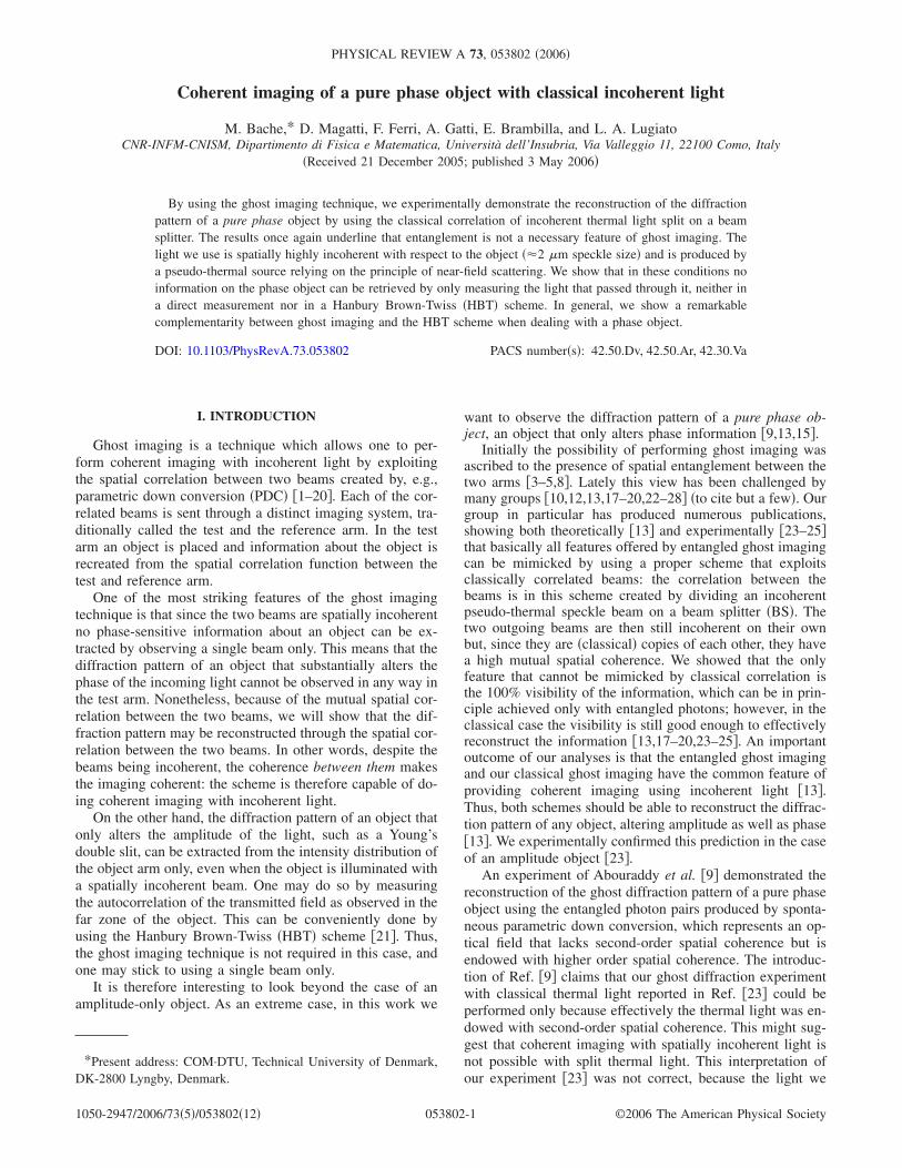
We then reinserted the scattering media to measure theghost diffraction pattern of the TGBS from the cross corre-lation between the two arms. A typical snapshot of what weobserve on the CCD is shown in Fig. 5�a�. The upper partcontains the reference arm intensity. For the correlation, weselected a narrow strip �128 pixel wide� centered around y=0 and extending over the entire x axis �1024 pixels�. In thetest arm no spatial information was extracted since there wecollected the light from a single fixed pixel. Initially we lo-cated the pixel in the test arm at the point x1=0 �pixel atposition P2 in Fig. 5�a��, and we measured the cross correla-tion �I1�x1= P2�I2�x2�� as a function of x2 varying in the re-gion shown by the white frame in Fig. 5�a�, by averagingover 18 000 snapshots. As seen from Eq. �9� this gives adiffraction pattern that is centered on x2=0. In this case weare able to reconstruct only the n=−1, 0, and +1 peaks, be-cause the higher order peaks are outside of the referenceregion imaged on the CCD. In order to reconstruct also then= ±2 peaks, we repeated twice the measurement by shiftingthe test arm pixel at the positions P1 and P3, respectively�see Fig. 5�a��, so that the the diffraction pattern emergingfrom the correlation shifts accordingly, as dictated by Eq. �9�.
The results of these measurements are shown in Fig. 5�b�,which plots the cross correlation scaled to �If�x2��2. The 2-D
reconstructed diffraction patterns are shown close to their cutalong the x direction, for each positioning of x1. Since eachdiffraction peak covers only few pixels, the x cuts of Fig.5�b� only give a qualitative image of the diffraction pattern,but do not allow a quantitative estimation of the peakheights, due to the poor sampling. In order to extract therelative height of the peaks, we located groups of pixels hav-ing a substantial value above the noise floor and added to-gether their values, which effectively corresponds to integrat-ing over each peak. The results are shown in Fig. 6 andcompared with those obtained from coherent laser illumina-tion with the same technique. We observe that they agreeextremely well: we have successfully created the correct dif-fraction pattern of the pure phase object from the correlation.Also notice that the n= ±1 peaks are recorded twice, and then=0 is recorded three times: these overlaps happen whendisplacing the single pixel position, and they agree very well
FIG. 5. Experimental demonstration of ghost diffraction of apure phase object using incoherent classical light. �a� Snapshot ofthe speckles recorded by the CCD in the far-field plane. The refer-ence beam is in the upper region and the white frame shows theregion used for the correlation. The test arm is in the lower region,and the white symbols indicate the three different single-pixel po-sitions used for the correlation. �b� Ghost diffraction patterns recon-structed via the cross correlation between the test and the referencearm, measured by locating x1 at each of the three pixel positions,and by varying x2 �18 000 averages�. The 2-D plots of the crosscorrelation G�x1 ,x2� / �If�x2��2 are shown as functions of x2−x1, to-gether with their 1-D cut in the horizontal direction.
BACHE et al. PHYSICAL REVIEW A 73, 053802 �2006�
053802-8

with each other. Finally, note that the position of the diffrac-tion peaks agree well with the theoretical prediction in Sec.III B.
As discussed in Sec. III A, the spatial average techniqueprovides a a faster and more efficient way of measuring theghost diffraction pattern. In this case the cross correlation ismeasured by varying both x2 and x1 for a fixed x2−x1. Theresults of this kind of measurement are shown in Fig. 7,where the upper part of the figure is a 2-D plot of the mea-sured cross correlation, and the lower part displays the inte-gral over the diffraction peaks compared to the laser illumi-nation results. Also in this case the agreement is excellent.From this figure we notice that only few averages over snap-shots are needed to reconstruct the diffraction pattern, be-cause a large number of averages over spatial points is per-formed, thus increasing the convergence rate �15,16�.Moreover the whole diffraction pattern is reconstructed in asingle measurement. Despite being much more efficient thanthe single-pixel reconstruction, the spatial average technique
does not follow the ghost imaging original spirit, whichassumes that the imaging information is extracted by onlyoperating on the reference arm. In this case, spatial informa-tion is also extracted from the test beam 1, by varying thepixel x1.
As a straightforward demonstration of the degree of inco-herence of the beams used, we present in Fig. 8 a measure ofthe autocorrelation function in the test arm Cauto�x1 ,x1��. Thisis measured by fixing x1� at position P2 and by varying x1, inthe same way as described in Sec. III C.
Evidently it does not reveal any significant informationabout the diffraction pattern. In fact, the first-order peaks arebarely visible and are at a level of 8% of the main peak, intrend with the prediction of the numerical results of Sec.III C. As argued in Sec. III A, this type of measurement isequivalent to a HBT-type scheme, and it works as an inco-herent imaging scheme when using incoherent light; in thiscase it is expected to give no information about a pure phaseobject. We can thus conclude that �i� the TGBS is truly apure phase object and �ii� the speckle light we use is trulyincoherent relative to the object.
C. Ghost diffraction versus HBT schemes: Case of partiallycoherent illumination
In this section we present results obtained by graduallyincreasing the spatial coherence of the light illuminating theobject. This is achieved by increasing the distance z betweenthe pseudo-thermal source and the object plane �see Fig. 1�.
We performed a second set of measurements with thisdistance set as z=115 mm. The measured autocorrelationof the light illuminating the object gave a speckle size�xn=14 �m �FWHM of the autocorrelation peak�. The mainresults obtained in these conditions are displayed in Fig. 9. Ina third set of measurements the object-source distance wasz=300 mm and the measured speckle size was �xn=33 �m.Figure 10 displays the results in this case.
By increasing the source-object distance the light gainssome partial coherence relative to the object. This is alreadyevident by the distribution of the speckles recorded in the farfield of the test arm, shown in the lower parts of frames �a� in
FIG. 6. Quantitative comparison between ghost diffraction andlaser illumination. The height of the diffraction peaks of the crosscorrelation shown in Fig. 5 are evaluated by performing an integralover the peaks. They are compared with peak values measured viacoherent laser illumination.
FIG. 7. Cross-correlation function �I2�x2�I1�x1��, calculated withthe spatial average technique. The upper part is a 2D plot of thecorrelation function �100 averages�. The lower plot displays theintegrals over the peaks compared with the results of laserillumination.
FIG. 8. Autocorrelation function �I1�x1�I1�x1��� of the test arm,measured by fixing x1� at position P2 and varying x1 �10 000averages�.
COHERENT IMAGING OF A PURE PHASE OBJECT¼ PHYSICAL REVIEW A 73, 053802 �2006�
053802-9

Figs. 9 and 10. Differently from the case of incoherent illu-mination, where the mean intensity distribution of the testarm is almost flat �see Fig. 5�a��, two broad peaks in corre-spondence to the n= ±1 diffraction orders are now clearlydistinguishable in the speckle distribution. As the coherenceof the light increases �Fig. 10�a�� they become narrower andmore pronounced. Notice that the zeroth-order peak is barelyvisible in these plots because its intensity is lower �as dic-tated by the TGBS�.
The cross correlation between the test and the referencearm, obtained by fixing x1 at position P2, is plotted in frames
�b� of Figs. 9 and 10. We see that by increasing the coher-ence of the light, the height of the ±1 diffraction peaks de-creases with respect the zeroth-order peak, and the diffrac-tion pattern gradually disappears from the cross correlation.Notice that these plots shows the “bare” cross-correlationfunction G�x1 ,x2� �i.e., there is no scaling factor �If�x2��2�.As predicted by Eq. �9�, the correlation scales with thesquare of the mean intensity of the reference arm, whoseprofile is plotted by the dashed lines in the figures. By in-creasing the near-field coherence, the far-field intensity spotbecomes narrower, until the mean intensity vanishes in theregion where the higher order diffraction peaks shouldemerge. In principle, the correct height of the diffractionpeaks could be recovered by dividing the correlation by�If�x2��2, but this operation also amplifies the noise in theregions where the intensity level is low. This is evident when
FIG. 9. Case of partially coherent illumination. The distancesource-object is z=115 mm, with �xn=14 �m. �a� Far-field speckledistribution in a single snapshot �upper part: reference arm, lowerpart: test arm�. �b� Cross correlation of the test and reference arm,for x1 fixed at the origin and 30 000 averages. The dashed curveshows the reference intensity squared. �c� Autocorrelation of the testarm light intensity. Full line: horizontal section of the autocorrela-tion function. Open triangles: peak values of the autocorrelation�integral over the peaks�. Circles: peak values measured with coher-ent laser illumination.
FIG. 10. The spatial coherence of the light illuminating the ob-ject is further increased: z=300 mm, �xn=33 �m. Frames �a�–�c�display the same quantities as in Fig. 9.
BACHE et al. PHYSICAL REVIEW A 73, 053802 �2006�
053802-10

the cross correlation is normalized, as shown in Fig. 11 �seealso Fig. 3�, and we notice that in the case of �xn=14 �mthe ±1 peaks can be almost reconstructed, while for�xn=33 �m they disappear in the noise.
In other words, by increasing the coherence, the signal-to-noise ratio for the reconstruction of the higher order peaksdecreases, and the information about the diffraction patternbecomes less and less accessible. To make this argumentmore formal, we remind that the signal-to-noise ratio is pro-portional to the visibility defined by Eq. �6�, as derived inRef. �24�. By using Eq. �8�, we can readily conclude thatfor G small the visibility of the nth-order peak, locatedat x2= x̄2, is V�G�x1 , x̄2� / ��I1�x1���I2�x̄2�����n�I2�x̄2�� /�I1�x1��. Since the point x1 is fixed at P2 where the test in-tensity is nonzero, the visibility, and hence the signal-to-noise ratio, is proportional to the intensity in the referencearm.
Conversely, by increasing the near-field coherence, thediffraction pattern gradually appears in the autocorrelationfunction of the test arm, displayed by frames �c� of Figs. 9and 10. In these plots the diffraction peak values measuredvia the autocorrelation �triangles� are compared to the valuesmeasured by coherent laser illumination �circles�. For �xn=33 �m the partial coherence of the light is already enoughto permit an almost perfect pattern reconstruction in the au-tocorrelation function.
The results presented in this section evidence a clearcomplementarity between the ghost diffraction scheme and
the HBT scheme, which will be further discussed in the nextsection.
A final remark is the following: had we used the spatialaverage technique, some information on the diffraction pat-tern would have been preserved in the correlation when in-creasing the spatial coherence. In this technique, in fact, thepixel position x1 in the test arm is scanned together with x2;in this way, if some information is present in the test armintensity distribution, this is retrieved from the correlation.By increasing the spatial coherence, the diffraction patternbecomes visible in the intensity profile of the test arm asshown by Figs. 9�a� and 10�a�, and becomes also visible inthe correlation as a function of x1. But, obviously, as thediffraction pattern appears in the test arm, is not possible anymore to speak about “ghost diffraction.”
V. CONCLUSION
We have shown that coherent imaging with incoherentclassical thermal light is able to produce the interference pat-tern of a pure phase object. This provides the ultimate dem-onstration that entanglement is not needed to do coherentimaging with incoherent light, not even in the case of a purephase object. As our group has pointed out in previous pub-lications �13,17–20,23–25�, the only evident advantage ofusing entangled light might be that of obtaining a better vis-ibility.
A remarkable aspect of the present experiment is the de-gree of incoherence of the pseudo-thermal speckle beamsused. In order to render the beams incoherent with respect tothe object �a standard transmission grating beam splitter with80 grooves per mm�, we had to create speckles which in theobject plane had a size of 2.0 �m. This was made possibleby exploiting the so-called near-field scattering �29,30�, inwhich the speckles are created so close to the source thattheir size is governed solely by the roughness of the scatter-ing medium.
In such conditions of spatial incoherence, we have shownthat no information on the phase object is present in the lightoutcoming from the object: neither the far-field intensity dis-tribution of the test arm nor its autocorrelation function�HBT scheme� reveal the diffraction pattern. This informa-tion is instead present in the cross correlation between thetest arm and a reference arm that never passed through theobject �ghost diffraction�. Our results indeed evidence that,when trying to extract information on a pure phase object,there exists a clear complementarity between the ghost dif-fraction scheme and the HBT scheme. In the HBT schemethe presence of a certain degree of spatial coherence is theessential ingredient that permits us to extract some phaseinformation, and the information becomes more correct asthe coherence increases. Conversely, the ghost diffractionscheme works as a coherent imaging scheme only thanks tothe spatial incoherence of the light, and the more the light isincoherent, the better the information is reconstructed. Theseresults contradict what was indicated in the introduction ofRef. �9�, where the possibility of doing coherent imaging in aghost imaging scheme employing split thermal light was as-cribed to the presence of spatial coherence.
FIG. 11. Cross-correlation function normalized to the squareof the mean intensity in the reference arm. �a� z=115 mm,�xn=14 �m: the ±1 peaks can still be reconstructed. �b�z=300 mm, �xn=33 �m: the diffraction peaks disappear in thenoise. Thirty thousand averages are performed for both frames.
COHERENT IMAGING OF A PURE PHASE OBJECT¼ PHYSICAL REVIEW A 73, 053802 �2006�
053802-11

ACKNOWLEDGMENTS
While finalizing this manuscript we were informed of another experimental observation of a phase object �33� byusing split thermal light. This work was carried out in theframework of the FET project QUANTIM of the EU, ofthe PRIN project of MIUR “Theoretical study of novel
devices based on quantum entanglement,” and of the INTASproject “Non-classical light in quantum imaging and continu-ous variable quantum channels.” M.B. acknowledges finan-cial support from the Carlsberg Foundation as well as TheDanish Natural Science Research Council �FNU, Grant No.21-04-0506�.
�1� D. N. Klyshko, Zh. Eksp. Teor. Fiz. 94, 82 �1988�, �Sov. Phys.JETP 67, 1131 �1988��.
�2� A. V. Belinskii and D. N. Klyshko, Zh. Eksp. Teor. Fiz. 105,487 �1994�, �JETP 78, 259 �1994��.
�3� D. V. Strekalov, A. V. Sergienko, D. N. Klyshko, and Y. H.Shih, Phys. Rev. Lett. 74, 3600 �1995�.
�4� T. B. Pittman, Y. H. Shih, D. V. Strekalov, and A. V. Ser-gienko, Phys. Rev. A 52, R3429 �1995�.
�5� P. H. S. Ribeiro, S. Padua, J. C. Machado da Silva, and G. A.Barbosa, Phys. Rev. A 49, 4176 �1994�.
�6� P. H. Souto Ribeiro, S. Padua, and C. H. Monken, Phys. Rev. A60, 5074 �1999�.
�7� B. E. A. Saleh, A. F. Abouraddy, A. V. Sergienko, and M. C.Teich, Phys. Rev. A 62, 043816 �2000�.
�8� A. F. Abouraddy, B. E. A. Saleh, A. V. Sergienko, and M. C.Teich, Phys. Rev. Lett. 87, 123602 �2001�; J. Opt. Soc. Am. B19, 1174 �2002�.
�9� A. F. Abouraddy, P. R. Stone, A. V. Sergienko, B. E. A. Saleh,and M. C. Teich, Phys. Rev. Lett. 93, 213903 �2004�.
�10� R. S. Bennink, S. J. Bentley, and R. W. Boyd, Phys. Rev. Lett.89, 113601 �2002�.
�11� R. S. Bennink, S. J. Bentley, R. W. Boyd, and J. C. Howell,Phys. Rev. Lett. 92, 033601 �2004�.
�12� A. Gatti, E. Brambilla, and L. A. Lugiato, Phys. Rev. Lett. 90,133603 �2003�.
�13� A. Gatti, E. Brambilla, M. Bache, and L. A. Lugiato, Phys.Rev. Lett. 93, 093602 �2004�; Phys. Rev. A 70, 013802�2004�.
�14� A. Gatti, E. Brambilla, and L. A. Lugiato, in Quantum Com-munications and Quantum Imaging, Vol. 5161 of Proc. ofSPIE, edited by R. E. Meyers and Y. Shih �SPIE, Bellingham,WA, 2004�, p. 192.
�15� M. Bache, E. Brambilla, A. Gatti, and L. A. Lugiato, Phys.Rev. A 70, 023823 �2004�.
�16� M. Bache, E. Brambilla, A. Gatti, and L. A. Lugiato, Opt.Express 12, 6067 �2004�.
�17� E. Brambilla, A. Gatti, M. Bache, and L. Lugiato, Fortschr.Phys. 52, 1080 �2004�.
�18� L. A. Lugiato, A. Gatti, E. Brambilla, and M. Bache, in Fluc-tuations and Noise in Photonics and Quantum Optics II, Vol.5468 of Proc. of SPIE, edited by P. Heszler, D. Abbott, J. R.Gea-Banacloche, and P. R. Hemmer �SPIE, Bellingham, WA,2004�, p. 262.
�19� A. Gatti, E. Brambilla, M. Bache, and L. A. Lugiato, LaserPhys. 15, 176 �2005�.
�20� M. Bache, L. Lugiato, A. Gatti, and E. Brambilla, in Proceed-
ings for II International Conference “Frontiers of NonlinearPhysics,” edited by A. Livtak �IAP RAS, Nizhny Novgorod,Russia, 2005�, p. 80.
�21� R. Hanbury-Brown and R. Q. Twiss, Nature �London� 177, 27�1956�.
�22� J. Cheng and S. Han, Phys. Rev. Lett. 92, 093903 �2004�.�23� F. Ferri, D. Magatti, A. Gatti, M. Bache, E. Brambilla, and L.
A. Lugiato, Phys. Rev. Lett. 94, 183602 �2005�.�24� A. Gatti, M. Bache, D. Magatti, E. Brambilla, F. Ferri, and L.
A. Lugiato, J. Mod. Opt. 53, 739 �2006�.�25� M. Bache, A. Gatti, E. Brambilla, D. Magatti, F. Ferri, and L.
Lugiato, quant-ph/0504081.�26� A. Valencia, G. Scarcelli, M. D’Angelo, and Y. Shih, Phys.
Rev. Lett. 94, 063601 �2005�.�27� K. Wang and D.-Z. Cao, Phys. Rev. A 70, 041801�R� �2004�.�28� Y. Cai and S.-Y. Zhu, Opt. Lett. 29, 2716 �2004�.�29� M. Giglio, M. Carpineti, and A. Vailati, Phys. Rev. Lett. 85,
1416 �2000�.�30� M. Giglio, D. Brogiol, M. A. C. Potenza, and A. Vailati, Phys.
Chem. Chem. Phys. 6, 1547 �2004�.�31� J. W. Goodman, Introduction to Fourier Optics, 2nd ed.
�McGraw-Hill, New York, 1996�.�32� J. W. Goodman, in Laser Speckle and Related Phenomena,
Vol. 9 of Topics in Applied Physics, edited by D. Dainty�Springer, Berlin, 1975�, p. 9.
�33� R. Borghi, F. Gori, and M. Santarsiero, private communication�2005�.
�34� It should be remarked that the HBT correlation vanishes in thelimit of full coherence, where the second-order correlation�I1I2� factorizes so that GHBT=0. However, this presumes bothspatial and temporal coherence. What we intend here, instead,is simply that we have large speckles on the object, implyingthus spatial coherence; the light is however temporally inco-herent.
�35� In fact, the observed diffraction pattern for a given speckle sizecan be understood as the Fourier transform of not the infinitelyextended grating, but instead the part of the grating that thespeckle is able to “see” due to its finite coherence. Thus, e.g.,�I1� obtained for �xn=48 �m corresponds �roughly� to the dif-fraction pattern of a transmission grating with four periods.
�36� Note that z=18 mm is only the geometrical distance, and thepresence of the half-inch glass cube BS should be taken intoaccount. In particular, when calculating the size of FFS or ofD*, the effective distance zeff that one should use is shorterthan z, because of the smaller divergence of light in glass thanin vacuum. In our case we estimate zeff�14 mm.
BACHE et al. PHYSICAL REVIEW A 73, 053802 �2006�
053802-12