cold formed steel rack
TRANSCRIPT
7/27/2019 cold formed steel rack
http://slidepdf.com/reader/full/cold-formed-steel-rack 1/9
The 14th
World Conference on Earthquake Engineering
October 12-17, 2008, Beijing, China
DYNAMIC ANALYSIS OF 2-D AND 3-D COLD FORMED STORAGE RACK
STRUCTURES WITH RIGID AND SEMI RIGID CONNECTIONS
K.M. Bajoria1
and K.K. Sangle2
1
Associate Professor Department of Civil Engineering, Indian Institute of Technology Bombay, Powai, Mumbai– 400 076 (India).
2
Corresponding author, Research Scholar Department of Civil Engineering, Indian Institute of Technology
Bombay, Powai, Mumbai – 400 076 (India).
(E-mail: : [email protected] , [email protected])
ABSTRACT:
Rack systems are very similar to the framed steelworks traditionally used for civil and commercial buildings,
but great differences in member geometry and in connection systems. In rack system, the beams are generally
boxed cross-section, and columns are open thin walled perforated section to accept the tabs of beamend-connectors. In storage racks, hook-in end connectors are used to make beam to column connections. Thesemi-rigid nature of this connection is primarily due to distortion of the column walls, tearing of the column
perforation, and distortion of the beam end connector. The structural behavior of storage racks for seismic loads
depends on how the individual components like beam to column connections, column bases and members
perform interactively with each other and therefore, it is important to have a proper way of predicting the
structural behavior of storage racks systems under seismic load. The complete 2 -D and 3 -D finite element
model of conventional pallet racking systems were prepared using the finite element program ANSYS. Free
vibration modal analysis and spectrum analysis carried out on pallet racks with the 18 types of column sections
developed along with semi -rigid connection . The principal aims were to find out fundamental time period,
mode shape and response to the spectrum acceleration of conventional pallet racking systems, made up of cold
form sections. Parameters selected for study are cross section of uprights, thickness of uprights, and stiffness ofthe connections.
KEY WORD : Dynamic analysis , pallet racks, cold formed steel, semi rigid joint
1. INTRODUCTION
One of the most significant uses of cold-formed members is for steel storage racking structures, such aspallet, drive in, and drive through racking systems. In typical pallet rack structure, generally, beams (stringers)have boxed cross sections, while columns (uprights) are open thin walled perforated to accept the tabs of beam
end connectors, which join beams and columns together without bolts or welds. Therefore design of pallet racks
is quite complex. The behavior of the perforated columns, that are generally thin walled members, is affected bydifferent buckling modes (local, distortional and global) as well as by their mutual interactions. The response of
beam to column is typically nonlinear. Moreover, bracing systems are generally placed only in the cross aisle
direction. The need for organizing pallet racks in such a way that the product is efficiently stored and
sufficiently accessible hampers the presence of bracings in the down aisle direction. Lateral stability is, hence,
provided by the sole degree of continuity associated with beam to column connections as well as by base plate
connections. The analysis and design of thin walled cold formed steel pallet racking frames structure with
perforated open upright section and semi rigid connections presents several challenges to the structural
engineers. Presently, for the design of these frames no specific code of practice exists. Although in the UnitedStates and some other countries the specification published by the Rack Manufacturer’s Institute (RMI) serves
as a guideline. Therefore analysis and design of pallet racks is quite complex under seismic load. Defining
7/27/2019 cold formed steel rack
http://slidepdf.com/reader/full/cold-formed-steel-rack 2/9
The 14th
World Conference on Earthquake Engineering
October 12-17, 2008, Beijing, China
engineering design, to the real behavior of a structure is provided by determining geometrical, damping massand connection model well. In design purposes; structures are designed as having such flexible connections in
which connection flexibility becomes important, are called “semi-rigid frames”. Semi-rigid frames are framesfor which the beam-to-column connections are neither pinned nor rigid. In reality all frames are semi-rigid,
because there is not a frame which has truly pinned and perfectly rigid connections. In the current design codes
no analysis or design guidance is given for semi-rigid frames. The traditional approaches to the design offrames are concisely described as continuous framing with rigid connections and /or simple framing with
pinned connections. However, the connection behavior significantly affects the displacements and internal force
distribution of framed structures.
In the current practice of stability analysis of steel-framed building structures, the actual behavior ofconnections is generally simplified to the two idealized extremes of either fully-rigid behavior or ideally-pinned
behavior. Although the adoption of such idealized connection behavior simplifies the stability analysis, it by nomeans represents the actual behavior of the structure. Therefore, the predicted response of the idealized
structure may be quite unrealistic compared to that of the actual structure. This is because most connections
used in current practice actually exhibit semi-rigid deformation behavior that can contribute substantially to the
stability of the structure as well as to the distribution of member force. Neglecting realistic connection behaviormay lead to unrealistic predictions of the response and strength of structures, and therefore, to approximations
in design.
2. CONNECTION IN STORAGE RACK
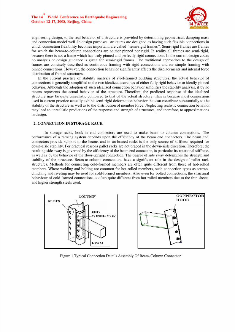
In storage racks, hook-in end connectors are used to make beam to column connections. Theperformance of a racking system depends upon the efficiency of the beam end connectors. The beam end
connectors provide support to the beams and in un-braced racks is the only source of stiffness required fordown-aisle stability. For practical reasons pallet racks are not braced in the down-aisle direction. Therefore, theresulting side sway is governed by the efficiency of the beam end connector, in particular its rotational stiffness,
as well as by the behavior of the floor-upright connection. The degree of side sway determines the strength andstability of the structure. Beam-to-column connections have a significant role in the design of pallet rack
structures. Methods for connecting cold-formed members are often quite different from those of hot- rolled
members. Where welding and bolting are common for hot-rolled members, such connection types as screws,
clinching and riveting may be used for cold-formed members. Also even for bolted connections, the structuralbehaviour of cold-formed connections is often quite different from hot-rolled members due to the thin sheetsand higher strength steels used.
Figure 1 Typical Connection Details Assembly Of Beam-Column Connector

7/27/2019 cold formed steel rack
http://slidepdf.com/reader/full/cold-formed-steel-rack 3/9
The 14th
World Conference on Earthquake Engineering
October 12-17, 2008, Beijing, China
This paper deals with the modal and spectrum analysis of a cold-formed steel storage rack structure, with rigidand semi rigid connections, under gravity and seismic load. Spectrum analysis is performed as per the spectrumgiven in IS 1893-2000.
3. COLUMN SECTION USED IN THE STUDY
In this paper open and torsionally strengthened sections were used. Original open sections were strengthened by
providing channel and hat stiffeners to avoid the local buckling of uprights. These sections are medium weight(MW) column section having three thicknesses 1.6 mm, 1.8 mm and 2.0 mm each with hat and channel stiffener
and HW (Heavy Weight) column section having three thicknesses 2.0 mm, 2.25 mm and 2.5 mm each with hatand channel stiffener. Their cross sectional geometry is given in figure 2 to figure 4. Purpose of choosing three
different thicknesses is to know the change in behavior when the sections are made locally stable by having
higher thickness.
3.1 Calculation of Sectional Properties of the Columns Used in the Study
For the above sections, sectional properties are calculated based on weighted average section. A weighted
average section is a section that uses an average thickness in the web portion to account for the absence of thematerial due to the holes along the length of the section and additional thickness for the additional material ofchannel and hat stiffener. Excel program is developed to calculate the sectional properties of sections used inthis study.
Figure 2 Medium Weight Sections 1.6, 1.8 and 2.0 mm
Figure 3 Heavy weight sections 2.0, 2.25 and 2.5 mm.
7/27/2019 cold formed steel rack
http://slidepdf.com/reader/full/cold-formed-steel-rack 4/9
The 14th
World Conference on Earthquake Engineering
October 12-17, 2008, Beijing, China
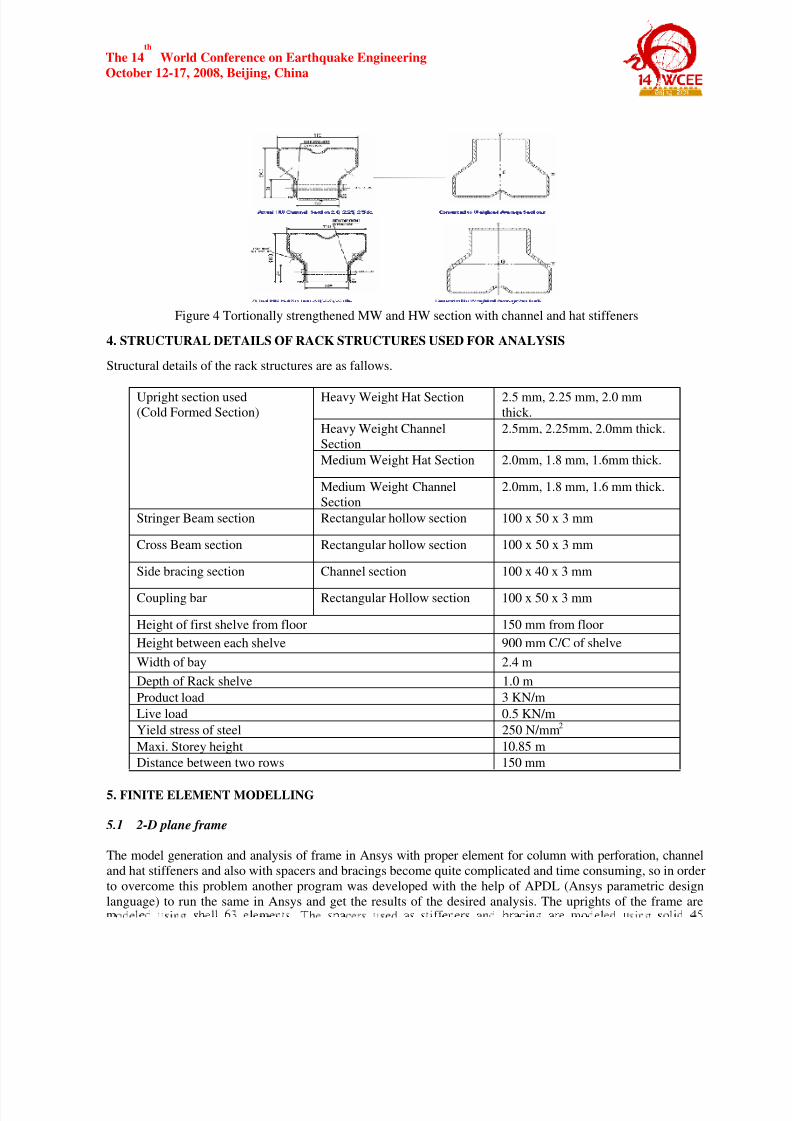
Figure 4 Tortionally strengthened MW and HW section with channel and hat stiffeners
4. STRUCTURAL DETAILS OF RACK STRUCTURES USED FOR ANALYSIS
Structural details of the rack structures are as fallows.
Heavy Weight Hat Section 2.5 mm, 2.25 mm, 2.0 mmthick.
Heavy Weight Channel
Section
2.5mm, 2.25mm, 2.0mm thick.
Medium Weight Hat Section 2.0mm, 1.8 mm, 1.6mm thick.
Upright section used (Cold Formed Section)
Medium Weight Channel
Section
2.0mm, 1.8 mm, 1.6 mm thick.
Stringer Beam section Rectangular hollow section 100 x 50 x 3 mm
Cross Beam section Rectangular hollow section 100 x 50 x 3 mm
Side bracing section Channel section 100 x 40 x 3 mm
Coupling bar Rectangular Hollow section 100 x 50 x 3 mm
Height of first shelve from floor 150 mm from floor
Height between each shelve 900 mm C/C of shelve
Width of bay 2.4 m
Depth of Rack shelve 1.0 m
Product load 3 KN/m
Live load 0.5 KN/m
Yield stress of steel 250 N/mm2
Maxi. Storey height 10.85 m
Distance between two rows 150 mm
5. FINITE ELEMENT MODELLING
5.1 2- D plane frame
The model generation and analysis of frame in Ansys with proper element for column with perforation, channeland hat stiffeners and also with spacers and bracings become quite complicated and time consuming, so in order
to overcome this problem another program was developed with the help of APDL (Ansys parametric designlanguage) to run the same in Ansys and get the results of the desired analysis. The uprights of the frame are
7/27/2019 cold formed steel rack
http://slidepdf.com/reader/full/cold-formed-steel-rack 5/9
The 14th
World Conference on Earthquake Engineering
October 12-17, 2008, Beijing, China
elements. Following a series of convergence studies, a mesh size of 5 mm x 5 mm is used for shell element.Properties of the finite elements used in the analysis in brief are given in table 1. Typical finite element model
shown in figure no 5. The finite element assumptions were as follows.
• The connection between the braces and columns were considered to be continuous.
•
At loading end of the upright all three rotations and displacement allowed and at the bottom base isassumed fixed.
• For the all the frame distance between solid spacers are kept 600mm.
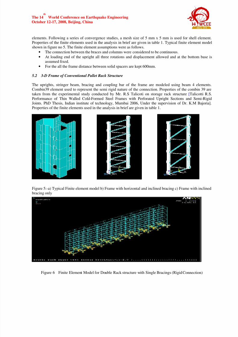
5.2 3- D Frame of Conventional Pallet Rack Structure
The uprights, stringer beam, bracing and coupling bar of the frame are modeled using beam 4 elements.
Combin39 element used to represent the semi rigid nature of the connection. Properties of the combin 39 are
taken from the experimental study conducted by Mr. R.S Talicoti on storage rack structure [Talicotti R.S.
Performance of Thin Walled Cold-Formed Steel Frames with Perforated Upright Sections and Semi-RigidJoints. PhD Thesis, Indian institute of technology, Mumbai 2006, Under the supervision of Dr. K.M Bajoria].
Properties of the finite elements used in the analysis in brief are given in table 1.
Figure 5:-a) Typical Finite element model b) Frame with horizontal and inclined bracing c) Frame with inclinedbracing only
Figure 6 Finite Element Model for Double Rack structure with Single Bracings (Rigid Connection)
7/27/2019 cold formed steel rack
http://slidepdf.com/reader/full/cold-formed-steel-rack 6/9
The 14th
World Conference on Earthquake Engineering
October 12-17, 2008, Beijing, China
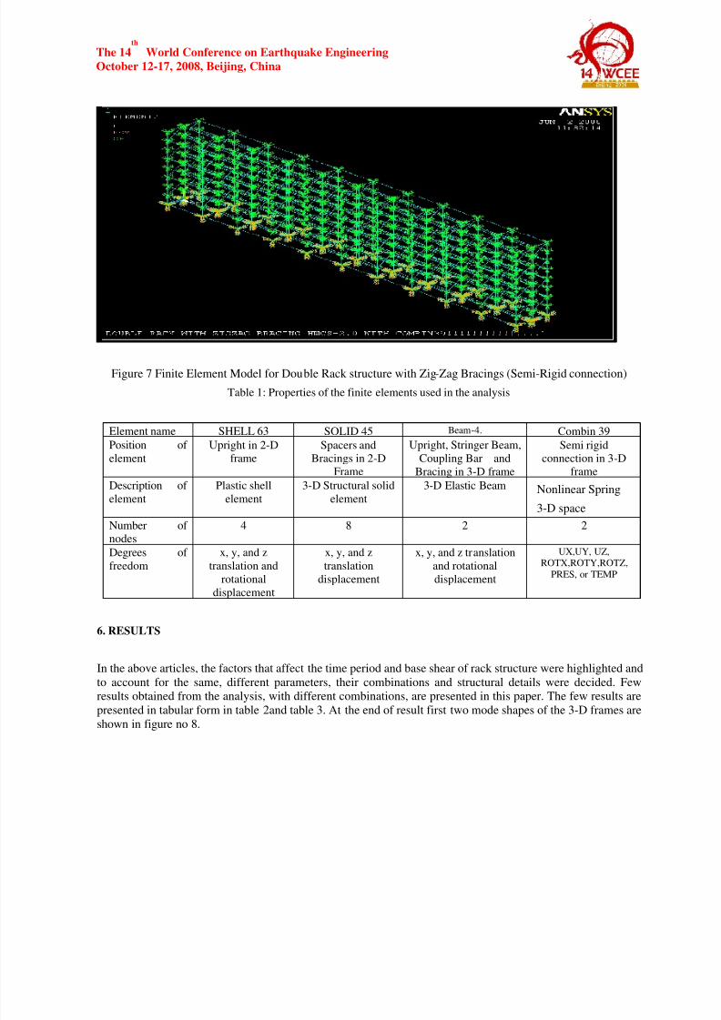
Figure 7 Finite Element Model for Double Rack structure with Zig-Zag Bracings (Semi-Rigid connection)
Table 1: Properties of the finite elements used in the analysis
Element name SHELL 63 SOLID 45 Beam-4. Combin 39
Position of
element
Upright in 2-Dframe
Spacers and
Bracings in 2-DFrame
Upright, Stringer Beam,
Coupling Bar andBracing in 3-D frame
Semi rigid
connection in 3-Dframe
Description of
element
Plastic shell
element
3-D Structural solid
element
3-D Elastic Beam Nonlinear Spring
3-D space
Number of
nodes
4 8 2 2
Degrees offreedom
x, y, and z
translation and
rotational
displacement
x, y, and z
translation
displacement
x, y, and z translationand rotational
displacement
UX,UY, UZ,ROTX,ROTY,ROTZ,
PRES, or TEMP
6. RESULTS
In the above articles, the factors that affect the time period and base shear of rack structure were highlighted and
to account for the same, different parameters, their combinations and structural details were decided. Fewresults obtained from the analysis, with different combinations, are presented in this paper. The few results are
presented in tabular form in table 2and table 3. At the end of result first two mode shapes of the 3-D frames areshown in figure no 8.
7/27/2019 cold formed steel rack
http://slidepdf.com/reader/full/cold-formed-steel-rack 7/9
The 14th
World Conference on Earthquake Engineering
October 12-17, 2008, Beijing, China
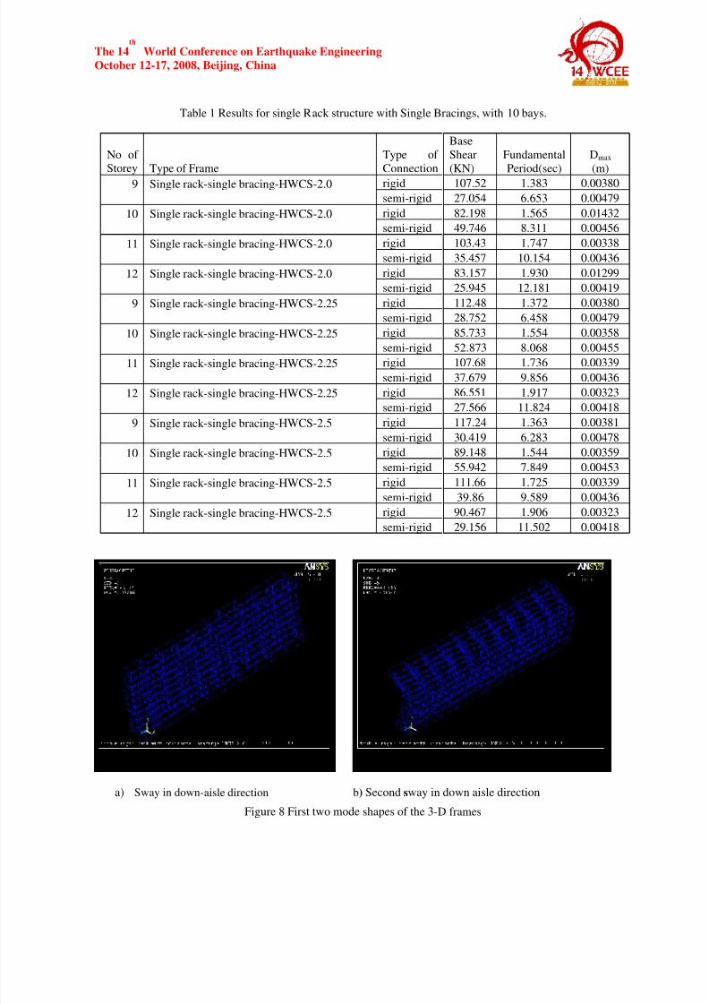
Table 1 Results for single Rack structure with Single Bracings, with 10 bays.
No ofStorey Type of Frame
Type ofConnection
Base
Shear (KN)
Fundamental Period(sec)
Dmax
(m)
rigid 107.52 1.383 0.00380 9 Single rack -single bracing-HWCS-2.0
semi-rigid 27.054 6.653 0.00479
rigid 82.198 1.565 0.01432 10 Single rack -single bracing-HWCS-2.0
semi-rigid 49.746 8.311 0.00456
rigid 103.43 1.747 0.00338 11 Single rack -single bracing-HWCS-2.0
semi-rigid 35.457 10.154 0.00436
rigid 83.157 1.930 0.01299 12 Single rack -single bracing-HWCS-2.0
semi-rigid 25.945 12.181 0.00419
rigid 112.48 1.372 0.00380 9 Single rack -single bracing-HWCS-2.25
semi-rigid 28.752 6.458 0.00479
rigid 85.733 1.554 0.00358 10 Single rack -single bracing-HWCS-2.25
semi-rigid 52.873 8.068 0.00455 rigid 107.68 1.736 0.00339 11 Single rack -single bracing-HWCS-2.25
semi-rigid 37.679 9.856 0.00436
rigid 86.551 1.917 0.00323 12 Single rack -single bracing-HWCS-2.25
semi-rigid 27.566 11.824 0.00418
rigid 117.24 1.363 0.00381 9 Single rack -single bracing-HWCS-2.5
semi-rigid 30.419 6.283 0.00478
rigid 89.148 1.544 0.00359 10 Single rack -single bracing-HWCS-2.5
semi-rigid 55.942 7.849 0.00453
rigid 111.66 1.725 0.00339 11 Single rack -single bracing-HWCS-2.5
semi-rigid 39.86 9.589 0.00436
rigid 90.467 1.906 0.00323 12 Single rack -single bracing-HWCS-2.5
semi-rigid 29.156 11.502 0.00418
a) Sway in down-aisle direction b) Second sway in down aisle direction
Figure 8 First two mode shapes of the 3-D frames
7/27/2019 cold formed steel rack
http://slidepdf.com/reader/full/cold-formed-steel-rack 8/9
The 14th
World Conference on Earthquake Engineering
October 12-17, 2008, Beijing, China
7. CONCLUSION
In this study, Flexible connections were located at the intersection of beam & column, were modeled
using a rotational springs, at the joint. The dynamic properties of the model so developed in ANSYS wereinvestigated with reference to modal attributes. Also the seismic analysis was performed by “Response Spectra”
method as available in ANSYS for both rigid as well as semi rigid model of rack structure, & correspondingresults were compared. The study compares these two models in lights on natural dynamic properties & base
shear obtained after spectrum analysis. This study gives important information about the differences which canbe occurred by modeling flexible connection as a rigid connection.The study indicates that connection models
have influences on the dynamic characteristics of the structure. Introduction of semi-rigid connection causesincrease in natural period of the structure, but the displacements were found to be increased. Also the semi-rigid
modeling of rack structure has reduced the base shear for the structure. Some of the important observations are
as follows
• Modeling the rack structure as Semi-Rigid makes the structure more flexible causing increase in natural
time Period of the structure.
• Secondly introducing the semi rigidity has caused reduction in the overall Base Shear for the structure.
• The max displacement for the structure has increased when rack modeled as semi-rigid.
•
Since the introduction of semi-rigidity in analysis of storage racks reduces the natural period of thestructure, therefore in spectrum analysis the values of spectrum acceleration to be considered are onlower side. The structure thus attracts lower values of base shear.
REFERENCES
Ali ugur oztruk and Hikmet H. Catal (2005) “Dynamic analysis of semi-rigid frames”, Mathematical and
Computational Applications, vol-10, No-1, pp-1-8.
Ali ugur oztruk and Hikmet H. Catal (2005) “An investigation for semi rigid frames by differentconnection models”, Mathematical and Computational Applications, vol-10, no-1, pp-35-44.
Talikoti R.S , Performance of Thin Walled Cold-Formed Steel Frames
with Perforated Upright Sections and Semi Rigid Joints. PhD Thesis 2005
Bajoria, K. M. and Talikoti, R. S., (2006), “Determination of Flexibility of Beam to Column Connectors
Used in Thin Walled Cold-Formed Steel Pallet Racking Systems”, ThinWalled Structures,44,772-80
IS: 1893 (Part I): 2002. “Criteria for Earthquake Resistant Design of Structures”.Bureau of
Indian Standard, New Delhi.
Talikoti, R. S. and Bajoria, K. M., (2005), New approach to improving distortional strength of intermediatelength thin walled open section columns, Electronic Journal of Structural Engineering, 5, 59-69.
Talikoti, R. S. and Bajoria, K. M., (2006), Torsional Enhancement of Frames usedin Pallet Racking Systems, Insdag’s Steel in Construction, .7, v1, 2536.
Anil K. Chopra, “Dynamics of Structure”
Mario Paz, “ Structural Dynamics”
7/27/2019 cold formed steel rack
http://slidepdf.com/reader/full/cold-formed-steel-rack 9/9
This document was created with Win2PDF available at http://www.daneprairie.com.The unregistered version of Win2PDF is for evaluation or non-commercial use only.