cold shrink - silicone...
TRANSCRIPT
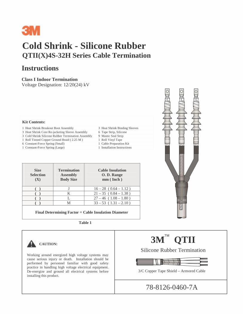
Cold Shrink - Silicone RubberQTII(X)4S-32H Series Cable Termination
Instructions
Class I Indoor TerminationVoltage Designation: 12/20(24) kV
3 Heat Shrink Core Re-jacketing Sleeve Assembly 6 Tape Strip, Silicone3 Cold Shrink Silicone Rubber Termination Assembly 9 Mastic Seal Strip1 Roll Tinned Copper Ground Braid ( 2.25 M ) 1 Roll Vinyl Tape6 Constant-Force Spring (Small) 1 Cable Preparation Kit1 Constant-Force Spring (Large) 1 Installation Instructions
SizeSelection
(X)
TerminationAssemblyBody Size
Cable InsulationO. D. Rangemm ( Inch )
( ) J 16 – 28 ( 0.64 – 1.12 )( ) K 21 – 35 ( 0.84 – 1.38 )( ) L 27 – 46 ( 1.08 – 1.80 )( ) M 33 – 53 ( 1.31 – 2.10 )
Final Determining Factor = Cable Insulation Diameter
Kit Contents:
1 Heat Shrink Breakout Boot Assembly 3 Heat Shrink Binding Sleeves
Table 1
3/C Copper Tape Shield – Armored Cable
3M QTIISilicone Rubber Termination
78-8126-0460-7A
CAUTION:
Working around energized high voltage systems maycause serious injury or death. Installation should beperformed by personnel familiar with good safetypractice in handling high voltage electrical equipment.De-energize and ground all electrical systems beforeinstalling this product.

78-8126-0460-7A2
! Temporary Vinyl Tape Band
Copper Tape Shield[A]
JacketRemovalLength
[A] + [B]
Maximum1.5 M
Do not attachcable mountingbracket within150 mm ( 6.0” )of jacket edge.
[C]
Bedding
Armor
10 mm (0.40”)
50 mm (2.0”)
25 mm (1.0”)
" Mastic Seal Strip
[B]
A. Prepare Cable
1. Determine cable jacket removal length required for correct core ( phase ) spacing and bolted terminal lug connections( [A] + [B], Figure 1 ), based on the longest phase to be connected. Allow for dimension [C] as needed.
Note: Individual core length and separation dimensions vary according to specific installation and equipment designrequirements. They must, therefore, be determined by the installer and must conform to accepted engineeringpractices. Supplied materials allow for a maximum [A] + [B] dimension of 1.5 M. See your local 3M Representativefor information regarding longer core length requirements.
2. Remove cable jacket, armor, bedding ( inner sheath ) and core fillers according to Figure 1 dimensions and equipmentrequirements. Secure copper tape shield ends with a temporary band of vinyl tape ( ! Figure 1 ).
3. Using light tension, apply one mastic seal strip around cable jacket 25 mm ( 1.0” ) below the cut edge ( " Figure 1 ).
Figure 1

78-8126-0460-7A3
B. Attach Metallic Shield Grounding Braids
1. Cut supplied tinned copper grounding braid into three equal 750 mm ( 30.0” ) lengths. Expand each braid end for a distanceof 300 mm ( 12.0” ) ( ! Figure 2 ).
2. Position one expanded ground braid end over each cable core shield as shown in Figure 3. Using vinyl tape bands, secureupper braid end to copper tape shielding 200 mm ( 8.0” ) beyond armor edge ( jacket edge for non-armored cable )( ! Figure 3 ). Secure to cable jacket 15 mm ( 0.60” ) below mastic seal strip ( " Figure 3 ).
3. Connect ground braid ends to cable core metallic shields using small constant force springs ( # Figure 3 ).
Armored cables: Connect three ground braids to cable armoring using one large constant force spring ( $ Figure 3 ).Following application, cinch ( twist with hand ) each spring to tighten.
4. Apply a second mastic seal strip over ground braids and previously-applied mastic strip ( % Figure 3 ).
5. Apply two highly stretched half-lapped layers vinyl tape over mastic seal strips and constant force springs ( & Figure 3 ).
Expand !
300 mm ( 12.0” )Ground Braid
Figure 2
Figure 315 mm (0.60”) 200 mm (8.0”)
"
Mastic Seal StripVinyl Tape Bands ( typical )
! Ground Braid OverCopper Tape ShieldNo Vinyl TapeIn This Area
2 nd Mastic Strip % $ Spring ( Large )
# Spring ( Small )
& Vinyl Tape

78-8126-0460-7A4
C. Install Heat Shrink Breakout Boot
1. Inspect breakout boot interior. Remove any contaminants that may be present.
2. Apply a single band of mastic around vinyl tape at position shown ( ! Figure 4 ).
Note: Disregard this step if using a breakout boot supplied with adhesive sealant.
3. Slide boot over cable as far as it will go ( " Figure 4 ). Using an appropriate torch, shrink breakout boot into final position.
Figure 4
Vinyl TapeMastic Band !
5 mm ( 0.20” )
"
78-8126-0460-7A5
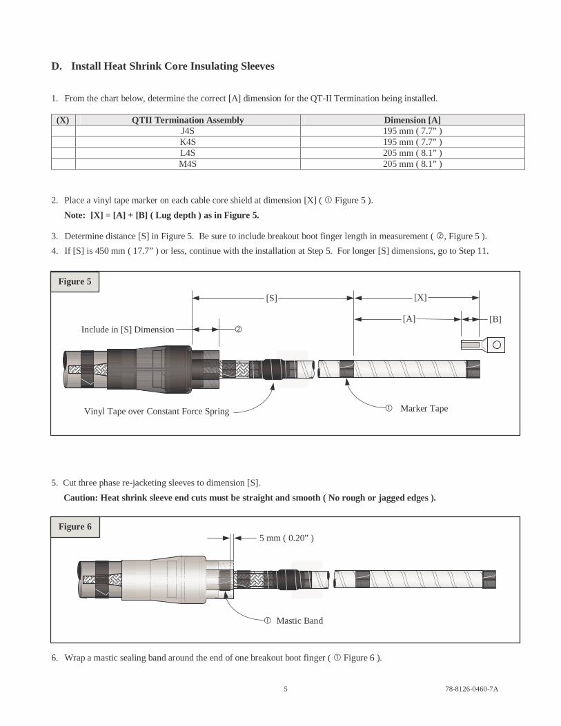
D. Install Heat Shrink Core Insulating Sleeves
1. From the chart below, determine the correct [A] dimension for the QT-II Termination being installed.
(X) QTII Termination Assembly Dimension [A]J4S 195 mm ( 7.7” )K4S 195 mm ( 7.7” )L4S 205 mm ( 8.1” )M4S 205 mm ( 8.1” )
2. Place a vinyl tape marker on each cable core shield at dimension [X] ( ! Figure 5 ).
Note: [X] = [A] + [B] ( Lug depth ) as in Figure 5.
3. Determine distance [S] in Figure 5. Be sure to include breakout boot finger length in measurement ( ", Figure 5 ).
4. If [S] is 450 mm ( 17.7” ) or less, continue with the installation at Step 5. For longer [S] dimensions, go to Step 11.
5. Cut three phase re-jacketing sleeves to dimension [S].
Caution: Heat shrink sleeve end cuts must be straight and smooth ( No rough or jagged edges ).
6. Wrap a mastic sealing band around the end of one breakout boot finger ( ! Figure 6 ).
Figure 5
Figure 6
[S]
[A] [B]
[X]
! Marker TapeVinyl Tape over Constant Force Spring
"Include in [S] Dimension
5 mm ( 0.20” )
! Mastic Band

78-8126-0460-7A6
7. Position one heat shrink re-jacketing sleeve over one shielded cable core and breakout boot finger ( Figure 7 ).
Note: Working on one core at a time will prevent unwanted adhesion between mastic sealing bands.
8. Repeat Steps 6. and 7. for the remaining two cable cores ( Figure 8 ).
9. Align each re-jacketing sleeve end with a termination marker tape ( ! Figure 9 ) and shrink into position.
Note: Maintain sleeve-to-marker tape edge alignment while shrinking. Shrink sleeves by progressing down fromthe marker tape edges to the breakout boot fingers. Never shrink both ends before moving to the centerregion of the heat shrink sleeve.
10. Allow heat shrink re-jacketing sleeves to cool before proceeding. Go to Section E., Page 8.
Heat Shrink Sleeve
Figure 9
Figure 7
Figure 8
! Align Sleeve andMarker Tape Edges
Vinyl Tape Marker Under Heat Shrink Sleeve
Heat Shrink Sleeve

78-8126-0460-7A7
11. For [S] dimensions longer than 450 mm ( 17.7” ) ( As measured in Figure 10 below ), add 100 mm ( 4.0” ) to [S].
12. Cut three heat shrink re-jacketing sleeves to dimension [ S + 100 mm ( 4.0” ) ].
Caution: Heat shrink sleeve end cuts must be straight and smooth ( No rough or jagged edges ).
13. Wrap a single mastic band around the end of one breakout boot finger ( ! Figure 10 ).
14. Position one heat shrink re-jacketing sleeve over one breakout boot finger and shielded cable core.
Note: Working on one core at a time will prevent unwanted adhesion between mastic sealing bands.
15. Repeat Steps 13. and 14. on remaining two cable cores ( Figure 11 ).
Note: Position three phase re-jacketing sleeves completely over breakout boot fingers. Extended length re-jacketing sleeves will cover previously applied termination marker tapes.
16. Starting at the breakout boot fingers, shrink re-jacketing sleeves into final position.
Note: Shrink from the lower end ( over breakout boot fingers ) to the upper end. Never shrink both ends beforemoving to the center region of the heat shrink sleeve.
17. Allow heat shrink sleeves to cool before proceeding.
Figure 10
Figure 11
Sleeves Completely Cover Breakout Boot Fingers
5 mm ( 0.20” )
[S]
! Mastic Band

78-8126-0460-7A8
18. Mark three installed re-jacketing sleeves at dimension [X].
Note: [X] = [A] + [B] ( Lug Depth ) as in Step D.1. and Figure 12.
Remove excess sleeve length to dimension [X].
Caution: Do not cut into cable metallic shielding while removing excess re-jacketing sleeve material.
E. Install QT-II Cold Shrink Termination Assemblies
1. Prepare cable phase ends according to dimensions shown ( Figure 13 ). Allow for crimp growth when using aluminumconnectors or lugs.
J-4S K-4S L-4S J-4S
A 195 mm ( 7.7” ) 195 mm ( 7.7” ) 205 mm ( 8.1” ) 205 mm ( 8.1” )B Lug Depth Lug Depth Lug Depth Lug DepthC 60 mm ( 2.4” ) 60 mm ( 2.4” ) 60 mm ( 2.4” ) 60 mm ( 2.4” )D 40 mm ( 1.6” ) 40 mm ( 1.6” ) 40 mm ( 1.6” ) 40 mm ( 1.6” )
Figure 13
Figure 12[X]
CBA
Re-jacketing Sleeve
D
[A] [B]
Mark Sleeves at Dimension [X]
Remove

78-8126-0460-7A9
2. Secure each metallic shield end with a single band of vinyl tape ( ! Figure 14 ). Center tape band on metallic shield edge.
Note: Do not extend vinyl tape wrap beyond width of tape roll.
3. From the free end of each installed shield grounding braid, cut a single, 150 mm ( 6.0” ) long, piece.
Note: In some kits, these shorter braid lengths may be supplied pre-cut.
4. Fully expand the diameter of each short braid. Slide one braid over each cable phase metallic shield ( " Figure 14 ).
Re-jacketing Sleeve
5. Secure ground braids to metallic shields using supplied constant force springs ( ! Figure 15 ).
Note: Make sure braid and springs are applied over cable metallic shields ( Not over vinyl tape ).
6. Wrap a mastic seal strip band over applied ground braid 5mm ( 0.20” ) from re-jacketing sleeve edge ( " Figure 15 ).
Figure 14
" Short Length Ground Braid
Figure 15
! Constant Force Spring
! Vinyl Tape Band
Applied Constant Force SpringMastic Band "
5 mm ( 0.20” )

78-8126-0460-7A10
7. Apply two highly stretched half-lapped layers vinyl tape over springs and mastic bands ( Figure 16 ).
Note: Do not extend vinyl tape wrapping more than 5 mm ( 0.20” ) beyond mastic band and ground braid leadingedge ( ! and " Figure 16 ).
8. Place a termination installation marker tape over each re-jacketing sleeve 100 mm from semi-con screen edge ( Figure 17 ).
9. Position heat shrink binding sleeves over ends of applied ground braids ( ! Figure 18 ). Shrink sleeves into position.
Figure 16
Vinyl Tape
Figure 17
100 mm( 3.9” )
Marker Tape Semi-con Screen
Figure 18
! Heat Shrink Binding Sleeve
Max. 5 mm ( 0.20” ) ! " Max. 5 mm ( 0.20” )

78-8126-0460-7A11
10. Special Applications – For terminal lug pads that will not pass through the interior of the termination assemblysupport core. Slide the termination assemblies over the cable phase legs before installing the lugs. Position eachtermination assembly with it’s loose core ribbon directed toward the open, lug end, of the cable ( Reference !, Figure 21as needed ). Continue with lug installations.
Normal Applications – Install Terminal Lugs:
For Aluminum Conductors - Thoroughly wire brush conductor strands to remove aluminum oxide layer. Immediatelyinsert conductor into terminal lug barrel as far as it will go.
Ensure that each lug face is parallel to it’s intended connection interface ( ! Figure 19 ).
11. Crimp terminal lugs according to manufacturer recommendations. Start at the upper end as shown ( " Figure 19 ).Remove all traces of oxide inhibitor that may have come out of the lug barrels during crimping.
Thoroughly clean primary insulation and lug barrel area using solvent wipes from supplied cable preparation kit.
Note: Avoid wetting cable semi-conductive layer with solvent.
12. Fill step at cable semi-con cut edge with silicone grease ( ! Figure 20 ).
Figure 20
Figure 19
! Silicone GreaseCable Semi-con
Last Crimp
!
" First Crimp
78-8126-0460-7A12
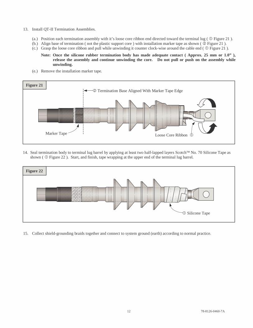
13. Install QT-II Termination Assemblies.
(a.) Position each termination assembly with it’s loose core ribbon end directed toward the terminal lug ( ! Figure 21 ).(b.) Align base of termination ( not the plastic support core ) with installation marker tape as shown ( " Figure 21 ).(c.) Grasp the loose core ribbon and pull while unwinding it counter clock-wise around the cable end ( ! Figure 21 ).
Note: Once the silicone rubber termination body has made adequate contact ( Approx. 25 mm or 1.0” ),release the assembly and continue unwinding the core. Do not pull or push on the assembly whileunwinding.
(e.) Remove the installation marker tape.
14. Seal termination body to terminal lug barrel by applying at least two half-lapped layers Scotch No. 70 Silicone Tape asshown ( ! Figure 22 ). Start, and finish, tape wrapping at the upper end of the terminal lug barrel.
15. Collect shield-grounding braids together and connect to system ground (earth) according to normal practice.
! Silicone Tape
Figure 21
Figure 22
" Termination Base Aligned With Marker Tape Edge
Marker Tape Loose Core Ribbon !

78-8126-0460-7A13
3M and Scotch are trademarks of 3M
Important Notice
Before using this product, you must evaluate it and determine if it is suitable for your intended application. You assumeall risks and liability associated with such use.
Warranty; Limited Remedy; Limited Liability. This product will be free from defects in material and manufactureas of the date of purchase. 3M MAKES NO OTHER WARRANTIES INCLUDING, BUT NOT LIMITED TO,ANY IMPLIED WARRANTY OF MERCHANTABILITY OR FITNESS FOR A PARTICULAR PURPOSE. Ifthis product is defective within the warranty period stated above, your exclusive remedy shall be, at 3M’s option, toreplace or repair the 3M product or refund the purchase price of the 3M product. Except where prohibited by law, 3Mwill not be liable for any loss or damage arising from this 3M product, whether direct, indirect, special, incidentalor consequential regardless of the legal theory asserted.
Electrical Products Division6801 River Place Blvd.Austin, TX 78726-9000http://www.3M.com/elpd © 3M 2002 QTII(X)4S-32H