collaborative project grant agreement number...
TRANSCRIPT

1
URBAN-WATER
Grant Agreement: 318602
Project Title:
Intelligent Urban Water Management System
Project Acronym:
Seventh Framework Programme
Collaborative Project
Grant Agreement Number 318602
Subject:
D2.2 – Multiprotocol gateway system requirements – WP2.2
Dissemination Level: PRIVATE
Lead beneficiary: Sagemcom Energy&Telecom SAS
2
URBAN-WATER
Grant Agreement: 318602
Revision Preparation date Period covered Project start date Project Duration
01 Month 5 Months 5 to 6 December 2012 30 Months

3
URBAN-WATER
Grant Agreement: 318602
Table of Contents
1 Introduction ...................................................................................................................................... 5
1.1 UrbanWater Project Description ............................................................................................... 5
1.2 Work package 2 overview ........................................................................................................ 5
2 Reference Documents ..................................................................................................................... 7
2.1 Standards and Norms .............................................................................................................. 7
2.2 Intelligent Urban Water Management System project documents .......................................... 10
2.3 Legal Documents ................................................................................................................... 11
3 Glossary ......................................................................................................................................... 12
4 Smart Metering system architecture ............................................................................................... 16
4.1 Overview ................................................................................................................................ 16
4.2 Network elements .................................................................................................................. 18
4.3 Operational objectives ............................................................................................................ 19
4.4 Technical challenges and constrains ..................................................................................... 20
4.5 Security and Privacy .............................................................................................................. 21
5 User requirements .......................................................................................................................... 23
5.1 Water Resources management .............................................................................................. 23
5.2 Raw Water Transfer management ......................................................................................... 25
5.3 Water Treatment management .............................................................................................. 26
5.4 Transmission System management ....................................................................................... 26
5.5 Demand and Leakage Management ...................................................................................... 27
5.6 Conclusions ........................................................................................................................... 28
6 System functional requirements ..................................................................................................... 31
6.1 Functional scope .................................................................................................................... 31
6.2 Operational Use Cases .......................................................................................................... 32
6.3 Metering Device requirements ............................................................................................... 45
6.4 LAN requirements .................................................................................................................. 49
6.5 Multiprotocol Gateway requirements ...................................................................................... 49
6.6 WAN requirements ................................................................................................................. 55
4
URBAN-WATER
Grant Agreement: 318602
6.7 IT Front End Platform requirements ....................................................................................... 55
6.8 Requirements of the Automated Billing System (ABS) in the “Wide Area Network” ............... 57
6.9 Security and Privacy .............................................................................................................. 59
7 Conclusion ..................................................................................................................................... 60
5
URBAN-WATER
Grant Agreement: 318602
1 Introduction
1.1 UrbanWater Project Description
Improving the efficiency of water management in Europe is recognized as essential for overcoming the growing exposure of European countries to increasing populations and water scarcity & droughts.
The objective of the UrbanWater Project (http://urbanwater-ict.eu/) is to enable better end-to-end water management in developed regions, which accounts for 17% of freshwater demand in the European Union.
The project will develop an innovative ICT (Information & Communication Technology) based platform for the efficient, integrated management of water resources. The system will benefit consumers, water utilities, public authorities, the environment and the general public, in terms of:
• providing consumers with comprehensive tools enabling them to use water more efficiently thereby reducing overall consumption
• helping water utilities to meet demand at reduced costs • fostering new partnerships between stakeholders so as to ensure the successful development
of the system and the evolution of the European Water Sector as a global leader.
The system will likely incorporate;
• advanced metering solutions • real-time communication of supply / demand data • new data management technologies with real-time predictive capability • supply / demand forecasting • demand pattern interpretation • decision support systems • adaptive pricing • user empowerment solutions
The UrbanWater consortium includes ICT companies, research organizations, water utilities and authorities with complementary capacities and know-how. Two water utilities included in the group will undertake large-scale validations on their water supply systems, thus promoting a final outcome that is close to the market and to the consumers. The final outcome of the project will remain open and interoperable with energy and water management schemes, thus positively impacting not only water consumption, but overall usage of natural resources throughout Europe.
1.2 Work package 2 overview
1.2.1 Task 2.1 - Data collection devices benchmark analysis (Lead by CRIC)
The aim of Task 2.1 is to perform a benchmark study to analyze different solutions already used in the water sector to collect data from customers, the distribution network and reservoirs.

6
URBAN-WATER
Grant Agreement: 318602
Different types of metrics will be proposed in terms of hardware/software (e.g. power consumption, range, network topology, etc.), commercial aspects, as well as standardization in order to evaluate already commercialized AMR products and research solutions recently developed by EU projects (among others SyncSen and WiMBex solutions).
Once the individual AMR analysis is performed, the Smart Metering Infrastructure (SMI) as a whole shall be considered including installation costs (devices, labor), infrastructure governance tools (features, real time), security and privacy issues and maintenance (Costs, repair times, battery life) to assess the study.
In parallel to this, an assessment of existing measurement equipment and techniques dedicated to leakage control and detection will be performed. This consolidation analysis shall include not only a benchmark analysis but also propose improved methods for noise, pressure and flow measurement, and value added approach using integration methods for efficient leakage detection, including DMA analysis, dynamical pressure management and others.
Dams and reservoir monitoring products for water level detection will be also analyzed apart from integrated Reservoir Control Centers. The analysis will focus on autonomous products that send the gathered data wirelessly (normally via GSM) from the dam or the reservoirs to the data processor and special emphasis will be provided to solar battery powered devices.
Finally, and once AMR, WDN and WR analysis are concluded, a set of conclusions and proposed improvements will be provided in D2.1 - Analysis of proven technologies in AMR, WDN and WR to be delivered in M6. The proposed improvements will be considered in the final solution of the project.
1.2.2 Task 2.2 - Multi-meter gateway prototype (Lead by SAGEM)
The aim of this task is the design of a new gateway able to support different types of data protocols. The gateway will be in charge of connecting the metering devices with the core server of the solution through a single point.
The purpose is to accept multiple wireless technologies simultaneously in order to aggregate many meters in one single device. It concentrates on the point-to-point used in communications between the water meter nodes and the network base station. In many cases, repeaters are required to span the distance between meter nodes and the network base station. To reduce the number of repeaters and decrease maintenance cost, a Multi-protocol gateway will be developed.
This new gateway will use new RF (Radio-Frequency) raising technologies at 169MHz or 868MHz frequencies. These gateways would help to avoid most of the repeaters and deal with water meter data collection. Special attention will be paid to studying WM specific topology, in high density urban configurations.
The main purpose is to specify, prototype and tune the protocol stack that will enable the collection of data in most topologies and densities. Developing a single gateway will reduce Capex (Capital Expenditure) and Opex (Operating Expenditure) during the exploitation of the solution and is a key to develop smart collection networks.

7
URBAN-WATER
Grant Agreement: 318602
2 Reference Documents
2.1 Standards and Norms
2.1.1 General standards about Smart Metering Infrastructure
Reference Existing Standard Status Technical Committee
[R1] TR 50572 : Functional reference architecture for communications in smart metering systems
Approved CEN / CENELEC
[R2] EN 13757-1: Communication systems for meters and remote reading of meters – Part1: Data exchange EN 13757-1 is a standard established by CEN/TC 294 for Communication system for meters and remote reading of meters (non-electricity). This standard contains OBIS object definitions for non-electricity meters and is referencing other parts of EN 13757 series and standards from IEC/EN 62056 series (DLMS/COSEM), including local interfaces, lower and upper layers, data modelling.
EN 13757-1: in revision
CEN TC294
[R3] EN 50090-3-1: Home and Building Electronic Systems – Part 3-1: Aspects of Application – Introduction to the application structure
Approved CLC TC205
[R4] EN 50090-3-2: Home and Building Electronic Systems – Part 3-2: Aspects of application – User process for HBES Class 1
Approved CLC TC205
[R5] EN 50090-3-3: Home and Building Electronic Systems (HBES) – Part 3-3; Aspects of application – HBES Interworking model and common HBES data types
Approved CLC TC205
2.1.2 Conformance with EMC and radio standards
In general, conformity with the R&TTE Directive (1999/5/EC) is assumed. There is a series of general EMC and radio standards to demonstrate conformity with the R&TTE Directive (1999/5/EC) articles 3.1b and 3.2 respectively, which are relevant to situations where wireless communication is used; these are listed below.
Reference Existing Standard Status Technical Committee
[R6] Harmonized standards to demonstrate conformity with the R&TTE Directive (1999/5/EC) article 3.1b: - EN 300 113-1: Electromagnetic compatibility and radio spectrum matters (ERM); Land mobile service ;Radio equipment intended for the transmission of data (and/or speech) using constant or non-constant envelope modulation and having an antenna connection; Part 1: Technical characteristics and methods of measurement - EN 310 489-1: Electromagnetic compatibility and radio spectrum matters (ERM); Electromagnetic Compatibility (EMC) standards for radio equipment and services Part 1 Common technical requirements - EN 301 489-7: Electromagnetic compatibility and Radio spectrum Matters (ERM); Electromagnetic Compatibility (EMC) standard for radio equipment and services; Part 7: Specific conditions for mobile and portable radio and ancillary equipment of digital cellular radio telecommunications systems (GSM and DCS) - EN 301 489-8: Electromagnetic compatibility and Radio spectrum Matters (ERM); Electromagnetic Compatibility (EMC) standard for radio equipment and services; Part 8: Specific conditions for GSM base stations
Approved Approved Approved
[R7] Harmonized standards to demonstrate conformity with the R&TTE Directive (1999/5/EC) article 3.2:
Approved

8
URBAN-WATER
Grant Agreement: 318602
- EN 300 220-2: Electromagnetic compatibility and Radio spectrum Matters (ERM); Short Range Devices (SRD); Radio equipment to be used in the 25 MHz to 1 000MHz frequency range with power levels ranging up to 500 mW
2.1.3 Lower layer standards about Smart Metering Infrastructure
Existing Standard Status Technical Committee
[R8] ISO FDIS 22158: Input/output protocols and electronic interfaces for water meters – requirements (ISO/TC30/SC7)
Approved CEN TC 294
[R9] EN 50090-5-3: Home and Building Electronic Systems (HBES) – Part 5-3: Media and media dependent layers – Radio frequency
Approved CLC TC205
[R10] EN 13757-2: Communication systems for and remote reading of meters Part 2: Physical and Link Layer NOTE twisted pair, base band signaling (M-Bus.)
Approved CEN TC 294
[R11] EN 13757-4: Communication systems for meters and remote reading of meters - Part 4: Wireless meter readout (Radio meter reading for operation in the 868 MHz to 870 MHz SRD band)
EN 13757-4: in revision
CEN TC 294
[R12] EN 13757-5: Communication systems for and remote reading of meters - Part 5: Wireless relaying
EN 13757-5: in revision
CEN TC 294
2.1.4 Upper layer standards about Smart Metering Infrastructure
Reference Existing Standard Status Technical Committee
[R13] EN 13757-3: Communication systems for and remote reading of meters Part 3: Dedicated application layer NOTE (M-Bus.)
EN 13757-3: in revision
CEN TC 294
[R14] IEEE-1377: Utility Industry Metering Communication Protocol Application Layer (End Device Data Tables)
Approved IEEE
[R15] EN 14154 series: Water meters Approved CEN TC 92
2.1.5 WAN standards about Smart Metering Infrastructure
Reference Existing Standard Status Technical Committee
[R16] ISO/IEC 7498-1 (1994) Information Technology – Open Systems Interconnect – Basic Reference Model: The Basic Model
Approved ISO/IEC
[R17] ITU-T I.322 (02/99) - Generic protocol reference model for telecommunication networks
Approved ITU-T
[R18] Public Cellular Mobile Network (GSM/GPRS/EDGE/UMTS) Smart Card Platform for mobile communication systems of 2G, 3G and beyond - TS 102 221: Smart Cards; UICCTerminal interface; Physical and logical characteristics, - TS 102 223: Smart Cards; Card Application Toolkit (CAT), - TS 102 671 : Smartcards; Machine to Machine UICC; Physical and logical characteristics, - TS 102 225: Smart Cards; Secured packet structure for UICC based
Approved 3GPP

9
URBAN-WATER
Grant Agreement: 318602
applications, - TS 102 484:Smart Cards; Secure channel between a UICC and an end-point terminal.
[R19] 3GPP All the technologies currently specified by 3GPPP (GERAN, UTRAN, LTE, LTE Advanced Access Networks, CS, GPRS and EPC Core Networks, IMS Subsystem) are relevant in the context of the M2M services, including specifically the SM services. These technologies can be referenced by means of the following “umbrella” specifications: - TS 41.101 - TS 21.101 - TS 21.201 - TS 21.202
3GPP
[R20] TCP/IP IPv4, IPv6 Internet Protocol
RFC 791 IETF
[R21] UDP RFC 768 IETF
[R22] IPv4, IPv6 Internet Protocol, Version 6 (IPv6) Specification RFC 2460 IETF
[R23] Hypertext Transfer Protocol – HTTP/1.1 http://tools.ietf.org/pdf/rfc2616.pdf
RFC 2616 IETF
[R24] Network Time Protocol Version 4: Protocol and Algorithms Specification http://tools.ietf.org/pdf/rfc5905.pdf
RFC 1305, IETF
[R25] XML Extensible Markup Language (XML) 1.0 REC-xml-20001006
W3C
[R26] XML REC-xml-names Name spaces in XML W3C
[R27] STUN Simple Traversal of User datagram protocol through Network address translators (NAT)
RFC 3489 IETF
[R28] STOMP Simple Text Oriented Messaging Protocol
[R29] TR-069: CPE WAN Management Protocol, Issue: 1, Amendment 4 http://www.broadband-forum.org/technical/download/TR-069_Amendment-4.pdf
TR-069 Broadband Forum
[R30] TR-106: Data Model Template for TR-069-Enabled Devices, Issue: 1, Amendment 6 http://www.broadband-forum.org/technical/download/TR-106_Amendment-6.pdf
TR-106 Broadband Forum
[R31] Internet X.509 Public Key Infrastructure Certificate Management Protocol (CMP) http://tools.ietf.org/pdf/rfc4210.pdf Internet X.509 Public Key Infrastructure Certificate and Certificate Revocation List (CRL) Profile http://tools.ietf.org/pdf/rfc5280.pdf
RFC 4210 RFC 5280
IETF
[R32] OCSP X.509 Public Key Infrastructure Online Certificate Status Protocol RFC 2560 IETF
[R33] The Transport Layer Security (TLS) Protocol, Version 1.2 http://tools.ietf.org/pdf/rfc5246.pdf
RFC 5246 IETF
[R34] NAT/PAT Network Address Translation / Port Address Translation RFC 2766 IETF
[R35] DHCP Dynamic Host Control Protocol RFC 3396, 3315
IETF
[R36] Ethernet IEEE 802.3 IEEE 802.1
IEEE
[R37] USB Universal Serial Bus

10
URBAN-WATER
Grant Agreement: 318602
2.1.6 Security standards about Smart Metering Infrastructure
Reference Existing Standard Status Technical Committee
[R38] ISO/IEC 27001 : 2013
Information technology – Security techniques – Information security management systems – Requirements.
Final Draft July 2013
ISO/IEC
[R39] ISO/IEC 27002 : 2005
Information technology – Security techniques – Code of practice for information security management.
Approved ISO/IEC
[R40] IEC 62351
The different security objectives include authentication of data transfer through digital signatures, ensuring only authenticated access, prevention of
eavesdropping, prevention of playback and spoofing, and intrusion detection.
Partially Approved
IEC TC57
[R41] IEC 62443
ISA/IEC-62443 is a series of standards, technical reports, and related information that define procedures for implementing electronically secure Industrial Automation and Control Systems (IACS). This guidance applies to end-users (i.e. asset owner), system integrators, security practitioners, and control systems manufacturers responsible for manufacturing, designing, implementing, or managing industrial automation and control systems.
Work in process
IEC TC65
[R42] ISO 19790 :2012
Information technology -- Security techniques -- Security requirements for cryptographic modules
Approved ISO/IEC
[R43] ISO 15408 : 2009
Information technology -- Security techniques -- Evaluation criteria for IT security -- Part 1: Introduction and general model (15408-1) Part 2: Security functional requirements (15408-2) Part 3: Security assurance requirements (15408-3)
Approved
ISO/IEC
[R44] NIST IR 7628 : 2010 Vol. 1, Introduction Vol. 2, Privacy and the Smart Grid Vol. 3, Supportive Analyses and References
Approved NIST
2.2 Intelligent Urban Water Management System project documents
Reference Existing Standard Status Technical Committee
[R45] WP1 / D1.2 User Requirements in the water market
Draft SW
[R46] WP2 / D2.1 Analysis of proven technologies in AMR, WDN and WR Draft CRIC
[R47] WP3 / D3.1 Data management cloud platform system requirements Draft RED
[R48] WP5 / D5.1 Customers’ empowerment tools system requirements Draft ORGA
[R49] WP6 / D6.1 UrbanWater platform requirements definition Draft CRIC

11
URBAN-WATER
Grant Agreement: 318602
2.3 Legal Documents
Reference Existing Standard [R50] Directive 2000/60/EC of the European Parliament and of the Council of 23 October 2000
establishing a framework for the Community action in the field of water policy. [R51] Directive 2004/22/EC of the European Parliament and of the Council of 31 March 2004 on
Measuring Instruments [R52] Directive 95/46/EC of the European Parliament and of the Council of 24 October 1995 on
the protection of individuals with regard to the processing of personal data and on the free movement of such data.
[R53] Directive 2002/58/EC of the European Parliament and of the Council of 12 July 2002 concerning the processing of personal data and the protection of privacy in the electronic communications sector.
[R54] Directive 2006/24/EC of the European Parliament and of the Council of 15 March 2006 on the retention of data generated or processed in connection with the provision of publicly available electronic communications services or of public communications networks and amending Directive 2002/58/EC.

12
URBAN-WATER
Grant Agreement: 318602
3 Glossary
Additional functionality: function that a smart metering system provides over and above the metrological functions covered by the Measuring Instruments Directive.
Architecture: structure and behavior of the technology infrastructure of an enterprise, solution or system.
NOTE 1 Functional architecture can be viewed as the set of basic information processing capabilities available to an information processing system.
NOTE 2 Software architecture of a program or computing system is the structure or structures of the system, which comprise software components, the externally visible properties of those components, and the relationships between them.
NOTE 3 Hardware architecture refers to the identification of a system's physical components and their interrelationships.
Smart Metering Infrastructure (SMI): infrastructure which allows two way communications between the Head-End System and the meter(s) and may be linked to other in-house devices.
Automated Meter Management (AMM): also called Advanced Metering Management. Refers to smart metering actions requiring communication, for example, remote actions. AMM directly incorporates additional functionalities beyond AMR.
Automatic Meter Reading (AMR): technology for remotely obtaining metering data from an on-site meter by communication from an access point outside the premises. AMR technologies include handheld, mobile or fixed network technologies based on telephony platforms (wired and wireless), radio frequency (RF), or Power Line Carrier (PLC).
Data Concentrator (DC): also called multiprotocol gateway. Intelligent station in a hierarchical communications network where incoming data (generated by multiple meters) is processed as appropriate and then repackaged, relayed, retransmitted, discarded, responded to, consolidated, prioritized and / or increased to multiple messages. Data Concentrators may be installed either in single households (Home Area Network), either on public access points (Neighborhood Area Network).
NOTE Gateways work on all seven layers of ISO-OSI architecture. The main job of a gateway is to convert protocols between communications networks.
Companion Specification for Energy Metering (COSEM): interface model for communicating with metering device, providing a view of the functionality available through the communication interfaces.
NOTE. The modeling uses an object oriented approach.

13
URBAN-WATER
Grant Agreement: 318602
Device Language Message Specification (DLMS): ISO-OSI Application Layer specification, independent of the lower layers and thus of the communication channel, designed to support messaging to and from distribution devices in a computer-integrated environment.
NOTE. DLMS is specified in EN 62056-53 and is an evolution of the Distribution Line Message Specification specified in EN 61334-4-41.
Gateway: This term is used in the document as an equivalent to Multiprotocol Gateway, or Smart Metering Gateway.
Head End System (HES): central Data System exchanging data via the SMI of various meters in its service area.
NOTE. It communicates via a WAN directly or indirectly to the meters via NNAPs and LNAPs.
Home Area Network (HAN): in-house local network which interconnects domestic equipment and can be used for energy management purposes
NOTE. There can be multiple HANs inside a customer’s premises.
Index: for water metering, the current reading of the total volume (mass) passed through the meter
Interface: point or means of interaction between two systems
Interoperability: ability of a system to exchange data with other systems of different types and/or from different manufacturers.
Local Area Network (LAN): called also Neighborhood Network. Data communication network providing access to several premises and / or other neighborhood networks. Data Link between Smart Meters and Data Concentrators or Gateways.
Meter: also called Smart Metering Device. Instrument for measuring, memorizing and displaying the consumption of a commodity.
M-bus (meter bus): a communication standard (wired or wireless) for data exchange with end devices, including, but not limited to utility meters.
Meter data: meter readings that allow calculation of the quantity of electricity, gas, water or heat consumed over a period.

14
URBAN-WATER
Grant Agreement: 318602
Meter data thus may include daily and monthly meter readings, interval readings and actual meter register values.
Other readings and data may also be included (such as quality data, events and alarms).
Smart Meter: combination of the following meter-related functions from the reference architecture:
- Metrology functions including the conventional meter display (register or index);
- One or more additional functions. These may also make use of the display;
- Meter communication functions.
Neighborhood network: called also LAN. data communication network providing access to several premises and / or other neighborhood networks.
OBject Identification System (OBIS): system defining identification codes for commonly used data items in metering and other equipment.
NOTE specified in EN 62056-61 for electricity meters, in EN 13757-1 for non-electricity meters.
Open Systems Interconnection (OSI): framework for communications processes, defined by ISO, in which the process is divided into seven functional layers, arranged vertically with each having separate and defined responsibility. Each layer communicates only with the layer immediately above and below.
Privacy: safeguarding of personal data.
NOTE Personal data is defined by Directive 95/46/EC (document [R52]) as any information relating to an identified or identifiable natural person.
Smart grid: supply network that intelligently integrates the behaviour and actions of all users connected to it – generators, consumers and those that do both – in order to efficiently ensure a more sustainable, economic and secure supply.
Tariff: price structure (normally comprising a set of one or more rates of charge) applied to the consumption of a product or service provided to a consumer.
Use case: description of the interaction between one or more actors, represented as a sequence of simple steps
NOTE 1 Actors are entities that exist outside the system ('black box') under study, and which take part in a sequence of activities in a dialogue with the system to achieve a specific goal. Actors may be end users, other systems, or hardware devices.
NOTE 2 Each Use Case is a complete series of events, described from the point of view of the actor.

15
URBAN-WATER
Grant Agreement: 318602
Wide Area Network (WAN): extended data communication network connecting a large number of communication devices over a large geographical area. Data Link between Data Concentrators (Gateways) and Head End Systems.

16
URBAN-WATER
Grant Agreement: 318602
4 Smart Metering system architecture
The smart metering system architecture for Urbanwater project is designed in accordance with Functional Reference Architecture described in TR 50572 [R1] relevant to meeting the technical / data requirements of Mandate M/441 and [R45] User requirements in the water market
This system architecture is intended to comply with M/441European Mandate objective:
“A European standard comprising a software and hardware open architecture for utility meters that supports secure bidirectional communication upstream and downstream through standardized interfaces and data exchange formats and allows advanced information and management and control systems for consumers and service suppliers. The architecture must be scalable to support from the simplest to the most complex applications. Furthermore, the architecture must consider current relevant communications media and be adaptable for future communication media. The communication standard of the open architecture must allow the secure interfacing for data exchanges with the protected metrological block.”
4.1 Overview
Figure 1 below gives a simplified overview of functional entities and interfaces in a smart metering infrastructure; the boxes correspond to functions that in physical terms can be implemented in a number of different ways. Implementation choices shall be made during design phase of the project.
This document is concerned solely with the communications interfaces depicted in blue in Figure 1; the internal functions and interconnections of the metering end device are outside the scope of this document. The dotted lines H2 and H3 support additional functionalities to support the provision of energy efficiency and demand-side management services, and are out of the scope of this document.

17
URBAN-WATER
Grant Agreement: 318602
Figure 1 : Reference architecture diagram for smart metering infrastructure
A smart metering system always comprises (a) head end system(s) and metering end devices, together with the communication network between them, which may include :
• Wide Area Network (WAN) connecting the head end systems to the local systems or networks,
• Neighborhood Network (NN) covering a number of premises (optional),
• Local Network (LN) within the same premises (optional).
A Neighborhood Network, when present, is accessible through a Neighborhood Network Access Point, hereafter called “Data Concentrator”.
Similarly, a Local Network, when present, is accessible through a Local Network Access Point.
Metering end devices may have interfaces to communicate on the LN, the NN or the WAN. These are the M, C and G interfaces respectively and at least one of these should be present.
Access to end devices on the LN is provided by the Local Network Access Point (LNAP). A LNAP has one or more M and H2 interfaces to communicate with the end devices on the LN and one or more C or G interfaces to communicate on the NN and the WAN.
Similarly, access to end devices and to LNAPs on the NN is provided by the Neighborhood Network Access Point (NNAP) or Data Concentrator. A NNAP has a C interface to communicate with entities on the NN and a G interface to communicate through the WAN with the metering head end system(s). It may also have an H3 interface to home automation systems.
Because the Network Access Points (LNAP, NNAP) have to interconnect different networks and may need to translate protocols, they contain a gateway function.
The following figure presents a simplified application of smart metering reference architecture for UrbanWater project for the nominal scenario:
Figure 2 : Smart metering reference architecture for UrbanWater project for the nominal scenario

18
URBAN-WATER
Grant Agreement: 318602
Each metering device is equipped with a communication module providing LAN interface “C” type, ie. narrowband wireless bidirectional link.
The Neighbourhood Network Access Point is provided using a Data Concentrator (or ”Multiprotocol Gateway”), to be installed on a high point for radio coverage.
The Data Concentrator provides the interface to WAN using “W1” type, and the data interface to Head End System using “G2” type.
4.2 Network elements
A functional entity may be implemented in different physical devices depending on the configuration needs. Each functional entity may have application functions and in order to be able to participate in the system it should have communication functions. The communication functions include the interface handler to manage one or more interfaces.
4.2.1 Smart Metering Devices
The smart metering device is a combination of the following meter-related functions from the reference architecture:
• Metrology functions including the conventional meter display (register or index) that are under legal metrological control. When under metrological control, these functions shall meet the essential requirements of the MID;
• One or more additional functions not covered by the MID. These may also make use of the display;
• meter communication functions.
The power supply to the smart metering device may have bearing on the additional and communication functions.
Non-electricity meters, which measure water are typically battery-powered and this has important implications for the frequency and duration of data communication possible. The location and installation of meters may also be constraining factors. Battery life, which may be subject to national regulation and/or utility purchasing requirements, has to be taken into account in standardization and metering system design, and in the interests of efficiency, provision may need to be made for short communication packets.
The Smart Metering Devices are provided with the following interfaces :
• C interface to the Data Concentrator using a long range wireless media (NN)
• Optionally M interface to a local Gateway using a short range wireless media (LN)
• Optionally G1 interface to the Central System using a public wireless network
Within the scope of Urbanwater project, a C interface using a European standard is preferred, such as EN 13757 “wireless MBUS” [R11]. The detailed implementation of the NN protocol and interface shall be provided during the design phase of the project.
4.2.2 Data Concentrator (NNAP)
The gateway functionality of the Data Concentrator provides a connectivity infrastructure between meters and the central system. It utilizes two separate communication networks. It communicates with the central system via a WAN, and via a NN with the meters which it manages, The Data Concentrator
19
URBAN-WATER
Grant Agreement: 318602
is typically used for meter connection in configurations, where a dedicated WAN connection for a single meter is not desired.
In addition, the Data Concentrator may also comprise application functions. Data Concentrator application functions may include collecting and retaining data from one or several end devices on a scheduled or on-demand basis, forwarding this data, compressing data, sending commands etc.
Interfaces
The Data Concentrators are provided with the following interfaces:
• C interface to the Smart Metering Devices using a long range wireless media (NN)
• W1 interface to a public wireless network (WAN)
• Optionally W1 interface to a public wired network (WAN)
• G2 interface to the Head End System using a W1 interface
Within the scope of Urbanwater project, a W1 interface using a GPRS or 3G public wireless network is preferred ([R18], [R19]). Alternatively, a W1 interface using an Ethernet interface is envisaged. A G2 interface using Internet protocols is preferred ([R20] to [R33]).
4.2.3 Head End System
The Head End System is a central communication system that communicates with meters (metering end devices) either directly through the WAN, or using additional Neighborhood Networks via NNAPs.
Interfaces
The Head End System is provided with the following interfaces:
• W3 interface to a public IP network (WAN)
• G2 interface to the Head End System using a W3 interface
The focus of this document is limited to the WAN communication part of the Smart Metering system only. Data exchange with other systems e.g. systems for physical meter installation and meter asset management, though of importance in UrbanWater project, are beyond the scope of this document. HESs typically manages NAP communications, data security and meter reading pre-processing.
4.3 Operational objectives
The system shall provide data in a reliable way so that it can cover the System functional requirements defined here after.
Since, most of the equipment installed in the communication system includes storage memories, the operational objective of the multi-protocol gateway is not the most critical parameter;
Therefore, the operational objective for the multi-protocol gateway is set to 99%, i.e., in average, 23 h 45 per 24hour
This figure does not include defaults coming from the telecom operator infrastructure or installation process issues.

20
URBAN-WATER
Grant Agreement: 318602
4.4 Technical challenges and constrains
4.4.1 Water SCADA specifies and RF protocol impacts
Water meters are set in basements, cellars or any other difficult places difficult to reach with RF technologies.
It is difficult and expensive to find locations to have gateways installed. Therefore one should limit the number of these pieces of equipment by using long range technologies, especially because water metering data collection will not require a large bandwidth.
On the opposite side, in urban use cases, having a long range radio will increase the number of devices seen by a single gateway in a way that it may become impossible to have them all managed. It is then very important to be able to set the RF level of each transmitter so that RF spectrum is not polluted.
Hence, a special attention should be taken on the choice of these technologies, and it will be mandatory to have a bi-directional RF protocol with a RF level adaptation protocol.
In term of frequencies, 169MHz and 868MHz with narrow band technologies could fit for these applications. As far as protocols are concerned, one could refer to MBUS protocol as described in documents [R10],[R11],[R12] and [R13].
4.4.2 System upgradability considerations
The document “WP1 / D1.2 User Requirements” [R45] spots an extended list of types of equipment that can provide data that have to be uploaded via a multi-protocol gateway. This includes meters, but also a large range of all types of sensors.
All these devices may have different life cycles and may be changed over the time, because they are old, out of battery or just obsolete due to new features requirements.
Therefore, it is important to think the gateway as an evolutive platform, on both, electronic and software side.
4.4.2.1 Hardware evolution
The GATEWAY must integrate interfaces that will offer capability to add or change some of its modules. As an example, we can list the potential modules that would have to be changed in the field:
- WAN modules: if an IP based Ethernet should be included as a core feature, other WAN connections will need to be provided as an option, like GRPS, 3G or LTE modem to be able to fit to the local existing WAN technologies and their evolution during their life time.
- LAN Modules: there is today a large set of specifications defining potential protocols to talk to sensors (refer to section 2.1.1 Standards and Norms). As from today, there are a lot of researches going on, and some new technologies and protocols may rise during the gateway life time. In addition, a single GATEWAY may have to get data from several different sensors under various LAN technologies. Therefore it should be possible to change LAN modules and add some new ones.
- Additional memory. The type and the quantity of collected data may change over the time (addition of sensors, change of type of sensor change of service conditions,…) and it should be possible to increase the memory size.

21
URBAN-WATER
Grant Agreement: 318602
Based on these elements, the gateway should have some standard extension ports such as USB, SD, or mini SD. Some of these ports should be made available inside the gateway cabinet in order to offer protection (access, isolation or dust and water protection) to the optional modules being connected.
4.4.2.2 Software evolution
As for the hardware, the diversity of sensors exchanging data with the gateways means that a single gateway will need to dialog with a various number of types of protocols. This means that he software structure should be very flexible, modular and multitask..
Moreover, the software is subjected to changes during the live time of the equipment capability of changing only a part of it to solve issues is a must when WAN communication is based on GPRS technologies.
Technologies like Java or OSGI would provide these features and flexibility.
4.5 Security and Privacy
Water networks and AMM systems are considered as strategic in most of the European countries, for the following reasons:
- Control the quality of the distributed water. Sensors that may control the distribution should not be acceded by any unauthorized body.
- Privacy of transmitted data: AMM data give information on consumers behaving. Having this information in real time or over a long period of time would attempt to customer individual liberty and rights.
Therefore, there should be some encryption of data and protocols for both LAN and WAN communication levels.
Section 2.1.6 Security standards about Smart Metering Infrastructure of this document lists a whole set of standard that should be used as reference do deal with the security and privacy topics.
The multi-protocol gateway, with its modular software, should be able to follow the evolution of these standards in order to stay up to date.
4.5.1 LAN aspects
At the LAN level, there are no needs of strong encryption since the risk of data access or corruption is limited to one single sensor or meter. Massive system attacks are not easy to set since it would mean that ackers would need to set specific equipments all over the network and accees all the meters one after the other.
Each meter or sensor should have its own encryption key, set in production by the manufacturer so that ackers would have to set up a new complete process to read each of these keys.
Regular protocols such as AEN128 would provide de big enough level of security, at least for a start.

22
URBAN-WATER
Grant Agreement: 318602
4.5.2 WAN aspects
On the WAN side, gateways will concentrate data form a large number of devices and it is important to take even more care of security of the link from the gateway to the Head End Server.
Since we have an IP based link from the gateway to the Head End Server, regular IP protocols such as SSL could be implemented, assuming that the encryption keys are managed against section 2.1.6 standards.
This means that security aspects of the WAN have to be managed both at the gateway and the Head End Server. As a minimum, in its commercial and operational version, the Head End Server should provide a whole Fire Wall solution and a PKI system to have all gateway encryption keys can be strongly managed.
4.5.3 General structures
Based on these considerations, the general security management structure should be as described here after:
Figure 3 : General system security management structure
Note: On the LAN side, if the general requirements indicate that there should be some encryption made of the data link from the meter/sensor, the fact is that some equipment may have to be connected the gateway without supporting high security features, or with third party proprietary protocols. Thus, if it is decided that these meters should be connected, security level may be lower for these. However, this connection will only be possible if the gateway can manage to take care of the security for data exchanged by these sensors from the gateway to the Head End Server.

23
URBAN-WATER
Grant Agreement: 318602
5 User requirements
The following chapters are deducted from elements coming from the document [R46] “WP2 / D2.1 Analysis of proven technologies in AMR, WDN and WR” Part of the job made was to list all needed features to face water distribution network needs. From this work, we can get a list of properties for equipments set to fit with all these features, and from this it will be possible to define the associated requirements from the AMM perspective. The following tables will list all relevant parameters that may be monitored at each step of a Water Distribution Network and define the properties of each of these data.
It will be studied under aspects that may affect the AMM system, and mainly the following ones:
- Static of dynamic data - Type of equipment - One way or 2 way information - Periodicity - Bandwidth (high or low)
5.1 Water Resources management
5.1.1 Impounding Reservoirs
Data Static /
Dynamic Equipment
1 way / 2 ways
Periodicity Bandwidth
Capacity Static - - -
Level (max, min, actual) Dynamic Level
Sensor 1 way Low Low
Bathometric Information Dynamic Level
Sensor 1 way Low Low
Inflows (max, min, actual) Dynamic Level
Sensor 1 way Low Low
Outflows (max, min, actual) Dynamic Level
Sensor 1 way Low Low
Reservoir Control Curves TBD
Rainfall (max, min, actual) Dynamic Level
Sensor 1 way Low Low
Temperature (evaporation) Dynamic Temp. Sensor
Water Quality TBD
Costs Out of scope System
calculated

24
URBAN-WATER
Grant Agreement: 318602
5.1.2 Rivers
Data Static /
Dynamic Equipment
1 way / 2 ways
Periodicity Bandwidth
River Flows (max, min, actual) Dynamic Flow
Sensor 1 way Low Low
Compensation flows Dynamic Flow
Sensor 1 way Low Low
Inflows (max, min, actual) Dynamic Flow
Sensor 1 way Low Low
Outflows (max, min, actual) Dynamic Flow
Sensor 1 way Low Low
Abstraction flows (max, min, actual) Dynamic Flow
Sensor 1 way Low Low
Rainfall Dynamic Level
Sensor 1 way Low Low
Water Quality TBD Type
dependent Type
dependent Type
dependent
Costs Out of scope System
calculated
5.1.3 Groundwater / Boreholes
Data Static /
Dynamic Equipment
1 way / 2 ways
Periodicity Bandwidth
Level (Max, Min, Actual) Dynamic Level
Sensor 1 way Low Low
Pump duties (lift / flow rate) Dynamic Flow
Sensor 2 way Low Low
Flows (Max, Min, Actual) Dynamic Flow
Sensor 1 way Low Low
Inflows (max, min, actual) Dynamic Flow
Sensor 1 way Low Low
Outflows (max, min, actual) Dynamic Flow
Sensor 1 way Low Low
Water Quality TBD Type
dependent Type
dependent Type
dependent
Disinfection options / needs TBD
Disinfection costs Out of scope System
calculated
Costs Out of scope System
calculated

25
URBAN-WATER
Grant Agreement: 318602
5.1.4 Seawater (Desalination)
Data Static /
Dynamic Equipment
1 way / 2 ways
Periodicity Bandwidth
Plan Capacity Static
Throughput rates (min, max, actual) Dynamic Flow
Sensor 2 way Low Low
Flows (Max, Min, Actual) o Throughput costs (all costs to “Water into Supply” point e.g. works output meter)
Out of scope System
calculated
5.1.5 Other / Temporary
Data Static /
Dynamic Equipment
1 way / 2 ways
Periodicity Bandwidth
Input volumes (max, min, actual) Dynamic Flow Meter 2 way Low Low
Input costs Out of scope System
calculated
Input options e.g. tankering, temporary boreholes, bulk supplies from 3rd Parties, Cross Border transfers etc.
TBD
5.2 Raw Water Transfer management
5.2.1 Abstraction Point
Data Static /
Dynamic Equipment
1 way / 2 ways
Periodicity Bandwidth
Flow (max, min, actual) Dynamic Flow
Sensor 2 way Low Low
5.2.2 Transfer type
Data Static /
Dynamic Equipment
1 way / 2 ways
Periodicity Bandwidth
Pipe (gravity) Static
Pipe (pumped) Static
Aqueduct Static
River transfer Static
Open channel Static

26
URBAN-WATER
Grant Agreement: 318602
5.2.3 Flow rates
Data Static /
Dynamic Equipment
1 way / 2 ways
Periodicity Bandwidth
Maximum Static
Minimum Static
Constraints TDB
5.2.4 Pumps
Data Static /
Dynamic Equipment
1 way / 2 ways
Periodicity Bandwidth
Lift /flow Dynamic Flow
Sensor 1 way Low Low
Energy Cost Dynamic Electricity
meter 2 ways Low Low
5.3 Water Treatment management
The management of treatment processes is performed by a dedicated SCADA system that monitors all the useful data / information on site.
Therefore the management of Water Treatment is out of the scope of this document.
5.4 Transmission System management
The management of Transmission System is performed by a dedicated SCADA system that monitors all the useful data / information on site.
Therefore the management of Transmission System is out of the scope of this document.

27
URBAN-WATER
Grant Agreement: 318602
5.5 Demand and Leakage Management
5.5.1 District Meter Areas (DMAs): To inform current and historic consumption
demand profiles and provide data for leakage management
5.5.1.1 District Meter Area
Data Static /
Dynamic Equipment
1 way / 2 ways
Periodicity Bandwidth
Flow (15 minutes data) Dynamic Flow meter 1 way Low Low
Pressure (15 minutes data) Dynamic Pressure sensor
1 way Low Low
Demographic profiles (Household) Static
Commercial Profile (non-Household) Static
Demand Historic Dynamic Flow meter 1 way Low Low
Input Qty – Historic TBD System
calculated
Leakage / Variance Out of scope System
calculated
5.5.1.2 Weather
Data Static /
Dynamic Equipment
1 way / 2 ways
Periodicity Bandwidth
Temp (max, min, mean) Dynamic Flow sensor 1 way Low Low
Rainfall Dynamic Level
sensor 1 way Low Low
Number of days without rain Dynamic System
calculated
Season Dynamic System
calculated
5.5.2 Per Capita / Household Consumption (PCC / PHC): To inform current and historic
Household consumption demand profiles
Per Capita / Household Consumption can be either directly measured and monitored using smart metering devices, or estimated from the consumption data provided by a sample group of users, using DMAs.
In both scenarios, Smart Metering Devices need to be installed at measurement points with accurate metrology and continuous data communication capabilities.

28
URBAN-WATER
Grant Agreement: 318602
Data Static /
Dynamic Equipment
1 way / 2 ways
Periodicity Bandwidth
Flow Dynamic Flow meter 1 way Low Low
Pressure Dynamic Pressure sensor
1 way Low Low
5.5.3 Leakage: To monitor and report leakage to facilitate leakage management at the
Economic Level of Leakage to facilitate optimal supply management
The data / information used to perform leakage analysis is provided by DMA equipment described in 5.5.1.
Active leakage control activities and leakage asset investment are elements calculated from a set of other parameters collected all over the Water Distribution Network Therefore are out of the scope of the this project.
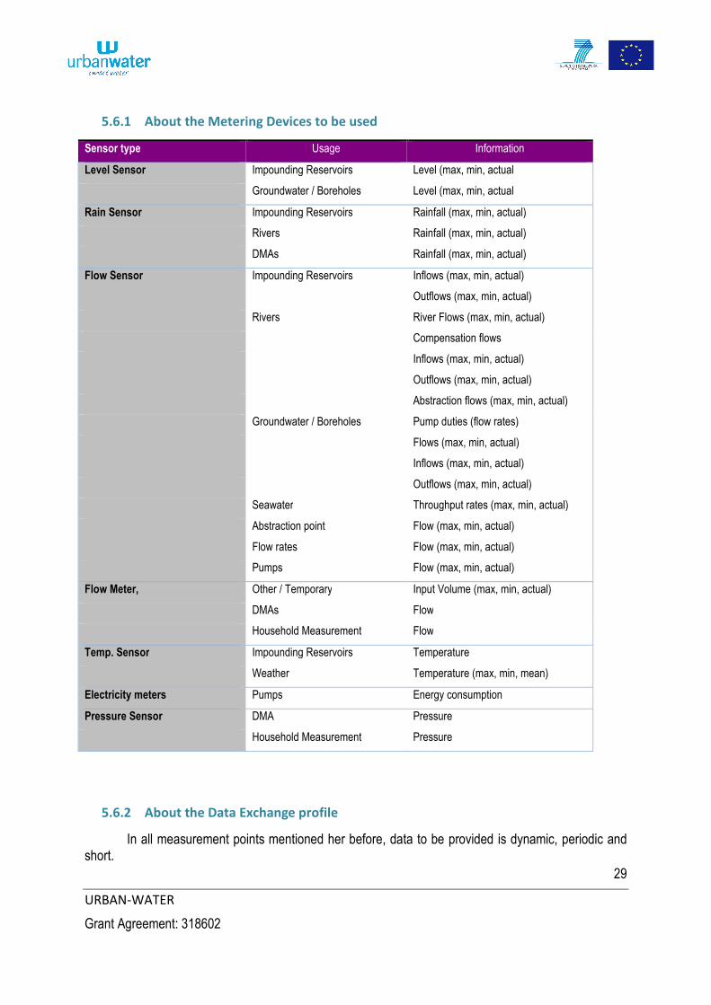
5.6 Conclusions
As a consequence, we are able to define a list of sensor type, based on the previous usages the network profiles requested.
29
URBAN-WATER
Grant Agreement: 318602
5.6.1 About the Metering Devices to be used
Sensor type Usage Information
Level Sensor Impounding Reservoirs Level (max, min, actual
Groundwater / Boreholes Level (max, min, actual
Rain Sensor Impounding Reservoirs Rainfall (max, min, actual)
Rivers Rainfall (max, min, actual)
DMAs Rainfall (max, min, actual)
Flow Sensor Impounding Reservoirs Inflows (max, min, actual)
Outflows (max, min, actual)
Rivers River Flows (max, min, actual)
Compensation flows
Inflows (max, min, actual)
Outflows (max, min, actual)
Abstraction flows (max, min, actual)
Groundwater / Boreholes Pump duties (flow rates)
Flows (max, min, actual)
Inflows (max, min, actual)
Outflows (max, min, actual)
Seawater Throughput rates (max, min, actual)
Abstraction point Flow (max, min, actual)
Flow rates Flow (max, min, actual)
Pumps Flow (max, min, actual)
Flow Meter, Other / Temporary Input Volume (max, min, actual)
DMAs Flow
Household Measurement Flow
Temp. Sensor Impounding Reservoirs Temperature
Weather Temperature (max, min, mean)
Electricity meters Pumps Energy consumption
Pressure Sensor DMA Pressure
Household Measurement Pressure
5.6.2 About the Data Exchange profile
In all measurement points mentioned her before, data to be provided is dynamic, periodic and short.

30
URBAN-WATER
Grant Agreement: 318602
5.6.3 About the Communication system
In all Measurement points, data is to be communicated from measurement point to Central System in a star topology network.
There is no communication from one measurement point to another measurement point.
Most of the communication needs are mono- directional unless parameters need to be set or firmware need to be upgraded, or because of security features implementation.

31
URBAN-WATER
Grant Agreement: 318602
6 System functional requirements
In this section, we shall define a list of tagged Use Cases, so that it will be possible to refer to them in the other elements of the UrbanWater project.
For the exercise, we shall limit the AMM system to Multiprotocol Gateway, and its nearby elements of the AMM system, i.e. smart metering devices or sensors or activators, on the one side, and the Central System on the other side. This document will not try to detail the structure of the Central system, but for each Use Case, we shall only indicate the features impacted by the Use Case itself, not trying to define which module of the Central System is impacted.
Thus, the studied System includes both LAN and WAN communication solutions.
6.1 Functional scope
Document [R45] “WP1 / D1.2 User Requirements in the water market” issue from the UrbanWater project draws a status regarding User Requirements. Some of them are relevant for the System and should be taken into account as System requirements
6.1.1 User Requirement 1
Description:
“Ideally, Water Authorities would look for fail-safe, automated, integrated water resources management systems, however […] there is a need for interactive use of any system to allow for planning of network changes e.g. treatments work outage, transmission main repairs etc., and also for scenario testing e.g. sensitivity testing of weather / demand relationships, consumption growth forecasts etc.”
User Requirement impacts:
There should be some end-to-end interactivity in the Smart Metering Device/ Smart Metering Devices / Central System part of the overall water AMI infrastructure. To offer this, there should be capacities to activate features, at any level of the System, to collect elements (data, configuration status,…) and take maintenance.
6.1.2 User requirement 2
Description:
“As such, in addition to running on-line with “real-time” data inputs, the UrbanWater Integrated Water Resources Management System will need to be able to be run “off-line”, with the facility to change key input parameters and modelling assumptions to test planning and scenario options.”
User Requirement impacts:
This has three impacts on the System requirements:
1. It should offer a real-time data inputs, and therefore Central System should be able to configure data transmissions.

32
URBAN-WATER
Grant Agreement: 318602
2. System configuration management: It should be possible to change the overall system, or only parts of its configuration with from the Central System.
3. System configuration may be simplified using configuration file to be downloaded into the relevant equipments of the network.
6.1.3 User requirement conclusion
These items are all addressed, in one way or another, in the next section under Operational Use Cases Studies.
6.2 Operational Use Cases
6.2.1 Providing accurate consumption reports to the central system
[UC-1.1] Providing actual user
consumption
periodically
Description:
This Use Case deals with the capacity of the system to deliver consumption reports form a meter to the central system.
System Impacts:
This Use Case means reliable communication solutions and storage capacity at all the levels of the data flow chain to face communication discontinuity.
Synopsis:
Refer to figure UC 1.1.

33
URBAN-WATER
Grant Agreement: 318602
[UC-1.2] Providing actual user consumption on demand
Description:
The Central System must be able, at any time, to request, from Smart Metering device, user consumption information.
Synopsis:
The Use Case follows the same process as in [UC-1.1] from Smart Metering Device to Central System. The latest meter index can be provided on demand by extracting the data from the central storage.
System Impacts:
Consumption data is available in the central data base.
[UC-1.3] Communicating the user data securely
Description:
Data should be protected of over the data flow chain so that the system may warrant that it is reliable, not corrupted and confidential.
Synopsis:
The Use Case follows the same process as in [UC-1.1] from Smart Metering Device to Central System.
System Impacts:
The Smart Metering device must get reliable consumption information.
Data communication must be encrypted, on both LAN and WAN sides, using appropriated solutions.

34
URBAN-WATER
Grant Agreement: 318602
[UC-1.4] Enabling to configure the
measurement interval
Description:
Central System can set, through the AAM system the data measurement period. Parameter should be set at relevant place: if possible, in the Smart Metering Device, if not, at the Smart Metering Gateway level.
Synopsis:
Refer to figure UC 1.4
System Impacts:
System must be a bi-directional system.
System latency must be managed.
[UC-1.5] Enabling to configure the communication interval
Description:
Central System can set, through the AAM system the uploading data measurement period. Parameter should be set at relevant place: in the Smart Metering Device, and at the Smart Metering Gateway level.
Synopsis:
Refer to figure UC 1.4
System Impacts:
System must be a bi-directional system.
System latency must be managed.
[UC-1.4] Enabling to configure the measurement interval
Receive
Frame
Send Status
Frame
XOR
Frame
to send
Cypher data
and create
frame
Error
Modify
Parameter
Value
Recei
ve
Mess
age
Parameter
Value
Stored
From
Configuration
Management
Send
request
Parameter
Value change
request
Receive
request
Broadcast
message
XOR
AND
Insert
Supervision
Data
Technic
al error
Store
Status Data
Status
Data
stored
Security
Check
Device
Authenticated
Filter
redondant
data
Filtered
Data
Create
Data fileXOR
Data File
to send
Technical
Error
Insert
Status
data
Send
Data File
XORError
Check
Error
Receive
Data File
Decypher and
check Data
Supervision
Data
To OAM
Management

35
URBAN-WATER
Grant Agreement: 318602
6.2.2 Providing environment information to the central system
[UC-2.1] Providing temperature data periodically
Description:
This Use Case deals with the capacity of the system to deliver periodic temperature information to the users. This use case is similar to 1.1.1[UC-1.1], but will be based on the use of a Temperature sensor; Storage capabilities of such a sensor might be limited; data transmission might even be broadcasted. In this case, storage capabilities are limited to the gateway storage capability.
Synopsis:
Refer to figure UC 1.1
System Impacts:
This Use Case means reliable communication solutions and big enough storage capacity at Smart Metering Gateway level.
[UC-2.2] Providing rainfall information periodically
Description:
This Use Case deals with the capacity of the system to deliver periodic rainfall information to the users. This use case is similar to [UC-1.1], but will be based on the use of a Rain sensor; Storage capabilities of such a sensor might be limited; data transmission might even be broadcast. In this case, storage capabilities are limited to the gateway storage capability.
Synopsis:
Refer to figure UC 1.1
System Impacts:
This Use Case means reliable communication solutions and big enough storage capacity at Smart Metering Gateway level.
[UC-2.3] Providing water quality information periodically
Description:
This Use Case deals with the capacity of the system to deliver periodic information regarding the quality of the water at a specific point of the distribution network. The sensor installed will be different and dependent from the type of information to collect or the type of place where it is installed.
However, this use case is similar to [UC-1.1],
Synopsis:
Refer to figure UC 1.1
System Impacts:
This Use Case means reliable communication solutions and big enough storage capacity at Smart Metering Gateway level.

36
URBAN-WATER
Grant Agreement: 318602
6.2.3 Providing water network information
[UC-3.1] Providing river flow data
Description:
This Use Case deals with the capacity of the system to deliver, on demand, or periodic information regarding the river flow status. This use case is similar to [UC-1.1], changing the Smart Meter Device to a Water Flow Sensor.
Synopsis:
Refer to figure UC 1.1
System Impacts:
This Use Case means reliable communication solutions and big enough storage capacity at Smart Metering Gateway level.
[UC-3.2] Providing Groundwater / Boreholes levels
Description:
This Use Case deals with the capacity of the system to deliver, on demand, or periodic information regarding the river flow status. This use case is similar to [UC-1.1], changing the Smart Meter Device to a Water Level Sensor.
Synopsis:
Refer to figure UC 1.1
System Impacts:
This Use Case means reliable communication solutions and big enough storage capacity at Smart Metering Gateway level.
[UC-3.3] Providing Groundwater / Boreholes levels
Description:
This Use Case deals with the capacity of the system to deliver, on demand, or periodic information regarding the Groundwater / Boreholes level status. This use case is similar to [UC-1.1], changing the Smart Meter Device to a Water Level Sensor.
Synopsis:
Refer to figure UC 1.1
System Impacts:
This Use Case means reliable communication solutions and big enough storage capacity at Smart Metering Gateway level.

37
URBAN-WATER
Grant Agreement: 318602
[UC-3.4] Providing Groundwater / Boreholes flows
Description:
This Use Case deals with the capacity of the system to deliver on demand, or periodic information regarding the Groundwater / Boreholes flow status. This use case is similar to [UC-1.1], changing the Smart Meter Device to a Water Flow Sensor.
Synopsis:
Refer to figure UC 1.1
System Impacts:
This Use Case means reliable communication solutions and big enough storage capacity at Smart Metering Gateway level.
[UC-3.5] Providing Seawater plant throughput data
Description:
This Use Case deals with the capacity of the system to deliver on demand, or periodic information regarding the seawater plant throughput data. This use case is similar to [UC-1.1], changing the Smart Meter Device to a Water Flow Sensor.
Synopsis:
Refer to figure UC 1.1
System Impacts:
This Use Case means reliable communication solutions and big enough storage capacity at Smart Metering Gateway level.
[UC-3.6] Providing Temporary input volume flow data
Description:
This Use Case deals with the capacity of the system to deliver temporary input volume flow data. This use case is similar to [UC-1.1], changing the Smart Meter Device to a Water Flow Sensor.
Synopsis:
Refer to figure UC 1.1
System Impacts:
This Use Case means reliable communication solutions and big enough storage capacity at Smart Metering Gateway level.
38
URBAN-WATER
Grant Agreement: 318602
[UC-3.7] Providing Raw water transfer flow data
Description:
This Use Case deals with the capacity of the system to deliver raw water transfer flow data. This use case is similar to [UC-1.1], changing the Smart Meter Device to a Water Flow Sensor.
Synopsis:
Refer to figure UC 1.1
System Impacts:
This Use Case means reliable communication solutions and big enough storage capacity at Smart Metering Gateway level.
[UC-3.8] Providing District Meter Area flow data
Description:
This Use Case deals with the capacity of the system to deliver District Meter Area flow data. This use case is similar to [UC-1.1], changing the Smart Meter Device to a Water Flow Sensor.
Synopsis:
Refer to figure UC 1.1
System Impacts:
This Use Case means reliable communication solutions and big enough storage capacity at Smart Metering Gateway level.
[UC-3.9] Providing District Meter Area pressure data
Description:
This Use Case deals with the capacity of the system to deliver District Meter Area pressure data. This use case is similar to [UC-1.1], changing the Smart Meter Device to a pressure sensor.
Synopsis:
Refer to figure UC 1.1
System Impacts:
This Use Case means reliable communication solutions and big enough storage capacity at Smart Metering Gateway level.

39
URBAN-WATER
Grant Agreement: 318602
6.2.4 Providing reservoirs level information
[UC-4.1] Providing Impounding Reservoirs level information
Description:
This Use Case deals with the capacity of the system to deliver Impounding Reservoirs level information. This use case is similar to [UC-1.1], changing the Smart Meter Device to a level sensor.
Synopsis:
Refer to figure UC 1.1
System Impacts:
This Use Case means reliable communication solutions and big enough storage capacity at Smart Metering Gateway level.
[UC-4.2] Providing Groundwater / Boreholes level data
Description:
This Use Case deals with the capacity of the system to deliver Groundwater / Boreholes level data. This use case is similar to [UC-1.1], changing the Smart Meter Device to a level sensor.
Synopsis:
Refer to figure UC 1.1
System Impacts:
This Use Case means reliable communication solutions and big enough storage capacity at Smart Metering Gateway level.
[UC-4.3] Providing Clear Water Tanks level information
Description:
This Use Case deals with the capacity of the system to deliver Water Tanks level information. This use case is similar to [UC-1.1], changing the Smart Meter Device to a level sensor.
Synopsis:
Refer to figure UC 1.1
System Impacts:
This Use Case means reliable communication solutions and big enough storage capacity at Smart Metering Gateway level.

40
URBAN-WATER
Grant Agreement: 318602
[UC-4.4] Providing In Network Service Reservoirs level data
Description:
This Use Case deals with the capacity of the system to deliver In Network Service Reservoirs level information. This use case is similar to [UC-1.1], changing the Smart Meter Device to a level sensor.
Synopsis:
Refer to figure UC 1.1
System Impacts:
This Use Case means reliable communication solutions and big enough storage capacity at Smart Metering Gateway level.
6.2.5 Enabling remote operations on the network
[UC-5.1] Enabling On-Off remote switching on water Pumps
Description:
Central System can set, through the AAM system some parameter values into the Smart Meter Device. This use case is similar to [UC-1.4], since we have to send an On/Off signal to a remote switching unit,
Synopsis:
Refer to figure UC 1.4
System Impacts:
System must be a bi-directional system.
System latency must be managed.
[UC-5.2] Enabling parameter value remote setting on smart meters
Description:
Central System can set, through the AAM system some parameter values into the Smart Meter Device. This use case is an extension to [UC-1.4],
Synopsis:
Refer to figure UC 1.4
System Impacts:
System must be a bi-directional system.
System latency must be managed.

41
URBAN-WATER
Grant Agreement: 318602
[UC-5.3] Enabling parameter value remote setting on smart gateway
Description:
Central System can set, through the AAM system some parameter values into the Smart Metering Gateway.
Synopsis:
[UC-5.3] Parameter value remote setting or trouble shooting Smart Gateway issues
Central SystemSmart Metering Gateway
To
Supersion
Managem
ent
Decypher
and check
DataInsert
Status
data
Data
File to
send
XOR
Send
request
Cypher
and Send
Data File
Super
vision
Data
Receive
Data File
Create
Data file
Receive
request
XOR
Parameter
Value
Stored
Check
Error
Parameter
Value
change
request
Error
To
Supersion
Manageme
ntError
Apply
Parameter
Value
Technical
Error
From
Configuration
ManagementXOR
System Impacts:
System must be a bi-directional system.
System latency must be managed.

42
URBAN-WATER
Grant Agreement: 318602
6.2.6 Monitoring maintenance information
6.2.6.1 Providing network equipment operational information
[UC-6.1] Troubleshooting Smart
Metering Device issues
Description:
This Use Case deals with the capacity of the system to get or Set Information for maintenance or trouble shouting into the Smart Metering Device.
Synopsis:
Refer to figure UC 6.1
System Impacts:
System must be a bi-directional system. There must be a real time access solution to the gateway and to the Smart Meter Device or a message queuing system if the Smart metering device is not 100% time connected.
[UC-6.2] Troubleshooting Smart Gateway issues
Description:
This Use Case deals with the capacity of the system to get information from the Smart Metering Gateway in order to understand its state and take hand over it in order to solve issues or make maintenance.
Synopsis:
Refer to figure UC 5.3
System Impacts:
System must be a bi-directional system. There must be a real time access solution to the gateway.
Sm
art
Mete
ring S
ensor
Sm
art
Mete
ring G
ate
way
Centr
al S
yste
m
43
URBAN-WATER
Grant Agreement: 318602
6.2.6.2 Enabling the preventive maintenance of the network
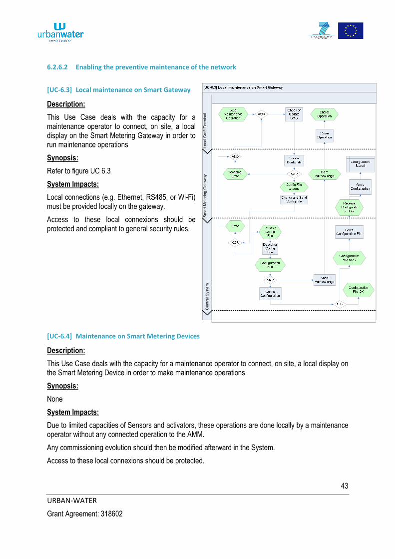
[UC-6.3] Local maintenance on Smart Gateway
Description:
This Use Case deals with the capacity for a maintenance operator to connect, on site, a local display on the Smart Metering Gateway in order to run maintenance operations
Synopsis:
Refer to figure UC 6.3
System Impacts:
Local connections (e.g. Ethernet, RS485, or Wi-Fi) must be provided locally on the gateway.
Access to these local connexions should be protected and compliant to general security rules.
[UC-6.4] Maintenance on Smart Metering Devices
Description:
This Use Case deals with the capacity for a maintenance operator to connect, on site, a local display on the Smart Metering Device in order to make maintenance operations
Synopsis:
None
System Impacts:
Due to limited capacities of Sensors and activators, these operations are done locally by a maintenance operator without any connected operation to the AMM.
Any commissioning evolution should then be modified afterward in the System.
Access to these local connexions should be protected.
Local C
raft
Term
inal
Sm
art
Mete
rin
g G
ate
wa
yC
entr
al S
yste
m

44
URBAN-WATER
Grant Agreement: 318602
6.2.6.3 Enabling the corrective maintenance of the network
[UC-6.5] Corrective
maintenance on
Smart Gateway
Description:
Central System can activate a connexion to the gateway in order to change configuration of the Smart Metering Gateway.
Synopsis:
Refer to figure UC 6.5
System Impacts:
System must be a bi-directional system.
System latency must be managed.
[UC-6.6] Remote download on Smart Gateway
Description:
Central System can update the Smart Metering Gateway remotely. This use case includes the capability to define the real date for the software change.
Synopsis:
Refer to figure UC 6.6
System Impacts:
System must be a bi-directional system.
Hardware structure of the Smart Metering Gateway must include a dedicated memory structure to deal with security over software download (two memory banks)

45
URBAN-WATER
Grant Agreement: 318602
[UC-6.7] Remote download on Smart Metering Devices
Description:
If permitted by the Smart Metering device type, Central System can update the Smart Metering Devise software remotely.
Synopsis:
This download is done in 3 steps:
- Download of the Smart Metering Device software to the Smart Metering Gateway (refer to synopsis UC 5.3).
- Download software from the Smart Metering Gateway to the Smart Metering Device. - Acknowledge the action
System Impacts:
System must be a bi-directional system.
Smart Metering Devices are often powered by batteries and have a limited size of memory. Therefore only a small number for Smart Metering Devices may offer this service.
6.3 Metering Device requirements
6.3.1 Smart Meter
The Smart Metering Device requirements can be directly deducted from the general functional analysis from the meter itself, a simple functional description of which is given in the following figure.
Figure 4: Smart Metering Device functional description
Metrology
Water volume
measurement
Water
consumption
display
Communication
Meter Data
storage
Meter Data time
stamping
Meter Data
registering
Meter Data
encryption
Meter Data
transmission
Operation
Meter remote
configuration
Meter firmware
download
Meter firmware
upgrade
Meter clock
synchronisation
Meter local
operation
Supervision
Tamper detection
Failure detection
Status report

46
URBAN-WATER
Grant Agreement: 318602
6.3.1.1 Metrology requirements
Description:
The metrology module is a module well isolated from the meter and it has its own requirements. However, we will limit the requirement in this document to the need of reliable metering information, in other words, an index.
For MID certification purposes, a local display must be available on the metrology module in order to let the customer confirm the index value by himself.
System Requirement:
Smart Metering Device metrological module must deliver a reliable index.
6.3.1.2 Meter Communication requirements
From the system point of view this is the most important part of the Smart Metering Device since it is the direct communication channel to the Smart Metering Gateway, and to the Central System.
6.3.1.2.1 Metering Data storage
Description:
Smart Metering Device should include some local memory in order to keep tracks of :
- All configuration parameters - Alarm statements - The latest index values obtained from the metrological module, and, if any historical data. This
is to face any lack in the LAN transmission strategy, that are usual when one get use of RF technologies.
System Requirement:
Smart Metering Device should include a local memory to keep local information in case of LAN communication issues
6.3.1.2.2 Metering Data encryption
Description:
Data coming from the Smart Metering Device must be protected from access (household information confidentiality) and corruption.
System Requirements:
1. Smart Metering Device must include a cyphering algorithm. 2. Smart Metering Device must have an initial encryption key set in factory to initiate data
communication to the system 3. System must include a commissioning process to make Smart Metering Device installation
simple and reliable.

47
URBAN-WATER
Grant Agreement: 318602
6.3.1.2.3 Metering Data radio communication
Description:
The Data Radio communication (LAN) to the meter must offer services previously studied in the Use Cases:
- Bi-directional communication solution - Low data rate - Asynchronous communication - Offer a solution with a good level of service in high density areas, but also, in order to limit the
number of installed Smart Metering Gateways, in areas where long RF range is required.
Moreover, the System should operate over frequencies where usage is free of charge or dedicated to utilities so that RF efficiency can be maximized.
System Requirement impacts:
1. RF LAN must be bi-directional 2. RF protocol must be optimized to fit in high and low density areas. 3. RF operational frequencies must be chosen in compliance with the European RF map.
6.3.1.3 Meter Operation requirements
6.3.1.3.1 Remote operations
Description:
In order to avoid maintenance on site, simple meter configuration and parameter status must be checked or set from the Central System level. Upload of the metrological data may also be forced. Local alarms must be acceded and cleared remotely.
These operations have to be provided with a communication strategy taking into account that Smart Metering Devices are often operating on battery cells energy.
System Requirement:
Central must have a mean of reading and setting remotely Smart meter internal parameters.
6.3.1.3.2 Firmware Download and upgrade
Description:
This impacts local memory size and RF transmission time.
Since Smart Metering Devices will, most of the time, operate on batteries, and meter costs have drastic constraints for household meters, this feature will not be studied under the present document.
System Requirement:
None
48
URBAN-WATER
Grant Agreement: 318602
6.3.1.3.3 Clock Synchronisation
Description:
Clock synchronisation is a must in order to stamp information for Smart Metering Devices, keeping tracks of historical data. Most of the water meter will not offer this feature. Therefore, it will not be studied under the present document.
In this case, the Smart Metering Gateway will have the data stamped at arrival.
System Requirement:
None
6.3.1.3.4 Local operations
Even if the AMI system provides remote management solutions to the meter, some local features must be provided on the Smart Metering Device. Under the scope of this document, we shall not consider local interfaces by themselves but only those linked to the AMI system and its installation process
Description:
During the Smart Metering Device installation on site, device must be associated to the installation site and to the customer contract, so that data collected by the given meter are properly used for billing.
This is also true for District meters, where collected data may, for instance, to be used for leakage detections.
System Requirement:
Smart Metering Device must be associated to a site and to a contract.
6.3.1.4 Meter supervision
Description:
The Central system needs to have a good vision of the state of the AMI Infrastructure. As a consequence, meters should be supervised. However, for cost issues, one need to keep these devices as simple as possible Thus, supervision of meters will be limited to alarm management, and only to tampering and fault detection alarms
System Requirements:
1. Smart Metering Devices will send alarm information to the Central system on tampering and fault detection cases.
2. Smart Metering Devices will keep a record of these alarms in its local memory until they are resettled by the central system.
49
URBAN-WATER
Grant Agreement: 318602
6.4 LAN requirements
Description:
In addition to topics raised in chapter 6.3.1.2.3, LAN must take into account the following facts:
- RF link are not naturally reliable; Protocols must provide redundancy in transmissions, in case of broadcast transmission of data, or hand check or acknowledgement features for critical data exchange. Redundancy or acknowledgement levels will have a direct impact on the view utilities administration teams and customers will have from the overall AMI system operating quality.
- RF equipments are often operating on batteries cells. Therefore, transmission durations, transmission slots synchronisation, data transmitted and RF transmission power must be tuned in order to minimize Energy consumption from the Smart Device point of view.
- There might be several LAN protocols active over a single water distribution network AMI infrastructure. These protocols may be installed during different version for the AMI infrastructure, due to distribution network evolutions. Therefore Smart Metering Gateway should be able to deal with various LAN protocols, and get software and/or hardware add-ons all over their life time.
- Chosen LAN protocols must be supported by official standards so that water utilities may easily find meters and sensors that can inter-operate with the Smart Metering Gateway.
System Requirements:
1. LAN protocol must provide redundancy data transmission or acknowledgement levels in line with operative goals of the overall system.
2. LAN protocol must be design in order to maximize Smart Metering Devices battery life.
3. Smart Metering Gateway must be an evolutive multi-protocol gateway.
4. Interoperability of LAN equipment is ensured by the use of communication standards.
6.5 Multiprotocol Gateway requirements
The Smart metering Gateway requirements can be directly deducted from the general functional analysis from the gateway itself, a simple functional description of which is given in the following figure:

50
URBAN-WATER
Grant Agreement: 318602
Figure 5: Smart Metering Gateway functional structure
6.5.1 Gateway Environment consideration
Description:
The Smart Metering Gateway is to be set at some strategic positions where the RF conditions are optimized so that the number of necessary gateways to run the System is minimized. Often, these sites are high places, on buildings’ roofs, or on top of water towers.
These sites may be difficult to access, and thus, the Gateway may have to be set outside of building, where hard climatic conditions will have to be taken in consideration. This includes humidity and temperature operating range, but also protection against rain and storm.
Access to these sites may also be difficult. A pre-setting of the Gateway may be taken into consideration so that the installation process is reduced to the minimum set of actions (physical installation). A quick check and a self-testing program should let the maintenance operator confident on the behaving of the gateway.
From this point, all configuration and provisioning may be done remotely.
The gateway must comply to general EMC regulations as exposed in documents [R6] and [R7].
System Requirements:
1. Gateway operation condition will take care of outside installation in unprotected areas. 2. Gateway installation process based on a self-testing program will be optimized.
Operation
Gateway remote
configuration
Gateway
firmware
download
Gateway
firmware upgrade
GatewayClock
synchronasation
Gateway local
opration
Power
mnagement
Main Power
Backup power
supply
LAN
Communication
Merter reading
Meter Data
storage
Meter
configuration
WAN
Communication
Gateway Data
encryption
Gateway Data
transmission
Supervision
Tamper detection
Failure detection
Status report

51
URBAN-WATER
Grant Agreement: 318602
6.5.2 Gateway operation
6.5.2.1 Remote operations
6.5.2.2 Description:
In order to avoid maintenance of gateway directly on site, all installation, commissioning and maintenance must be possible remotely on gateways.
Such operations can be run, one by one, on each single gateway, or automated so that mass actions may be launched on all gateways in one single action, for maintenance purpose.
Parameter status must be checked or set from the Central System level. Upload of the metrological data from the meter seen by the gateway may also be forced. Local alarms must be accessed and cleared remotely.
These operations should be possible, at any time, at the Central System initiative, and without delay,
System Requirement:
Central must have a mean of reading and setting remotely Gateway internal parameters.
6.5.2.3 Firmware Download and upgrade
Description:
As described in overviewed Use Cases, the gateway will get upgrade instructions from the Central System
The firmware upgrade will be done in several consecutive phases.
- Reception of a full firmware - Check of the software (integrity and origin of the firmware) - Switch from one firmware to another. - In case of functional issue with this new firmware, the switch back to the previous version of the
firmware must be possible. This is designed in order to avoid that, after a software download that would fail, one would have to send a maintenance operator to mend the gateway.
This configuration means that the structure of the firmware and the memory management is compatible with this process; in other words the software must include a mini-boot module and two banks of memory, each of which will be hosting a version of the software.
System Requirement:
Gateway memory management must permit, in case of firmware upgrade, a firmware downgrade, on command or automatically if the auto-test fails.

52
URBAN-WATER
Grant Agreement: 318602
6.5.2.3.1 Clock Synchronisation
Description:
Clock synchronisation is a must to stamp information for Smart Metering infrastructure. Therefore, the Gateway will, as often as necessary check from the Central System, the status of its internal clock. If any, the internal clock will be tuned. The NTP, IP based protocol could fit to this need.
There might be periods when the Gateway and the Central System may have difficulty exchanging information. This can be linked to default in the WAN communication chain or to the beginning of the installation process before the link to the Central System is activated. During this period the Gateway must maintain its own clock management, including if the power supply of the gateway fails for some period of time.
System Requirements:
1. The gateway must implement the NTP protocol so that it remains synchronized with the Central System.
2. The gateway must provide a local RTC.
6.5.2.4 Local operations
Description:
During the Gateway installation process, on site, the gateway must be associated to the installation site so that data collection of the nearby meters may be optimized.
These operations include parameter checking, parameter setting, software upgrade,
System Requirement:
The Smart Metering Gateway must support local operations. Therefore, there should be some local ports available. These accesses must be controlled and secured so that they cannot be any risk for the overall system security.
6.5.3 Gateway Power supply management
Description:
The Smart Metering Gateway will often be powered from the mains. However, since the Smart Metering Devices are often sending their data in a mono-directional broadcast mode to the gateway, having a power failure will most of the time mean loose of data. Therefore, a backup system should be added to the main power supply. This would probably be made using rechargeable battery cells.
There are also places where the main electricity grid is hard to find. In these cases, a solar panel solution would give more flexibity to the system.
System Requirements:
1. The Smart Metering Gateway must include a power supply backup solution, on internal or external additional battery cells.
2. The Smart Metering Gateway design must permit system evolution to solar panel power supply, (including its battery cells system).

53
URBAN-WATER
Grant Agreement: 318602
6.5.4 Gateway LAN Communication management
Description:
Regarding the LAN aspects of the Smart Metering Gateway, modularity must be offered on the hardware and software structure of the Gateway in order to let:
- Let the gateway operate several LAN protocols at the same time (run all together or one after the other in very short time slots). This may mean several LAN modules, in one or more technology.
- Let the gateway add or change the operated LANs, in order to fit to new technologies or new needs.
- Let the gateway offer a simple installation, via a modular hardware structure where LAN modules or antennas may easily be deported form the main Gateway housing.
There are several technologies that could fit for this modular approach: USB Ports on the Gateway, or the Ethernet using the Power Over Ethernet services.
The gateway must collect data form Smart Metering Devices in various situations such as Push or Pull modes (from the metering device point of view). This gateway must always be ready to receive frames from a Smart Metering Device.
Since the meter data acquisition is not linked to the WAN communication strategy to the Central System, the Gateway will have a local memory to store data before it can be uploaded. The size of the available memory will determine the number of Smart Metering Devices, a Gateway may deal with.
In case of power supply break down, the data received from the meter should be kept in the gateway memory.
System Requirements:
1. The Gateway must have a modular approach of the LAN modules on standards interfaces 2. Connexion of a LAN must be easy but must comply with all the general security rules of the
overall system. 3. RF strategy on the LAN must take care of the type of devices and be optimized so that there is
no data lost. 4. The gateway must have a local flash memory buffer to store metering data from the Smart
Metering Devices.

54
URBAN-WATER
Grant Agreement: 318602
6.5.5 Gateway WAN Communication management
Description:
WAN communication solutions will be based on existing third party networks. These Networks might not be available at all places where a Smart Metering Gateway is required. Therefore some alternate solutions have to be identified from the system perspective. The Gateway will have to manage these.
- RF Coverage: Gain antennas may be provided to increase the RF signal strength. - For cellular networks, roaming solutions may be possible. If not, the WAM Modem may include
several SIM cards to access several networks. - WAM Modem must stay modular so that they can be changed if cellular network operators
decide to stop operating a technology (moving technology from/to GPRS, 3G or LTE,…)
System Requirements:
1. The Gateway must host at least one WAN Modem (in addition to a local Ethernet interface). 2. WAM Modem must offer an antenna connector so that a gain antenna can be set on the
gateway 3. WAM modems must be connected the gateway on a identified interface. This modem can then
be changed during the life cycle of the Gateway.
6.5.6 Gateway Supervision management
Description:
The Central system needs have a good vision of the state of the AMI Infrastructure. As a consequence, Gateways should be supervised. The Smart metering Gateway will raise alarms on pre-determined events and report these to the Central System.
Alarm information may be sent immediately to the Central System in case of an emergency (e. g. tempering alarm), or the information may be kept stored in the Gateway until the next meeting point in the communication protocol between the Gateway and he Central system.
Alarms will remain active inside the Gateway database, until they are expressively cleared, locally by a maintenance operator, or remotely from the Central system.
System Requirements:
1. The Smart Metering Gateway will send alarm information to the Central system on tampering and fault detection cases.
2. The Smart Metering Gateway will keep a record of these alarms in its local memory until they are resettled by the central system.

55
URBAN-WATER
Grant Agreement: 318602
6.6 WAN requirements
Description:
For WAN communications, there are some existing standards with already existing networks available.
All these technologies, for interoperability purposes are now all TCP/IP or UDP/IP based protocols. There are two main candidate networks available for water AMI applications:
- When possible native IP over Ethernet (connexion to the IP grid via an ADSL or fibre Router) or company routers.
- Cellular phone network, using 2G, 3G, or even, in the coming years, 4G networks.
These two networks are chip and easy to access. In addition, it is possible to find repeaters for Cellular network, or get agreements with several communication operators if there are some areas where the cellular communication is too weak. But these networks also host other applications and user that share communication equipments and links. Therefore, a special attention should be taken to transmitted data and access, from these public networks to the water utilities infrastructure.
As far as application protocols are concerned there are many possible solutions.
In order to keep open the solution list, one should here too stick to standards and open protocols, so that it is easy to enhance existing interfaces both at the Gateway and the front-end Server level to face equipments and protocol evolutions.
Communication on the WAN may be subjected to fee payment. Therefore, the quantity of data exchanged must be carefully controlled. Metering data files should be wrapped together so that ZIP algorithm may be more efficient, one should avoid unnecessary “keep alive“ frames.
System Requirement:
1. Access from the WAN to the AMI equipments should be strongly protected by several layers of firewall.
2. Transmitted data (including both metering data and configuration and maintenance protocols) must be cyphered so that confidentiality, origin and reliability of these data are warranted over the WAN
3. Application and cyphering protocols should be standard protocols. 4. Control quantity of data exchanged over the WAN to the Front end Server.
6.7 Central System requirements
The Central system is a large set of servers that interact all together, and with the whole Automatic Metring Infrastructure.
The purpose of this document is not to describe the structure of such a computer system, but to identify elements that have a system impact on the multi-protocol gateway.
Thus, there are two main modules in the Central System that have been identified to interact with the Multi-protocol Gateway:
- The Head End Server : this module is in charge of collecting all communication flux over the WAN, to the Gateway
- The Automatic Billing System that will use the collected metering data;

56
URBAN-WATER
Grant Agreement: 318602
6.7.1 Head End Server requirements
Description
The general structure of the Front End Server is defined in the following figure:
Figure 6: Head End Server general architecture
The Front End server design must deal with the following main aspects
- Scalability: all the services offered by the AMR infrastructure must be able to grow over the years, with an investment cost increasing in parallel to its growth. Therefore, each service must be identified and a specific server must be dedicated and sized for it. Moreover, the Head End Server must provide load balancing solution and redundancy, so that a Central system failure would not have an impact on the AMI service rate.
- Security: the Head End Server must have several levels of firewall, giving a high level of protection to the core system. Communications are always initiated by the deeper part of the system, to a more external part so that uploaded data are always controlled before being stored. There is a PKI server managing key distribution for all the devices installed in sites and communication with the Head End Server
The Head End Server concentrates all the commutation links to the Gateway and to the Smart Metering Devices. Thus, collected data is exposed to all other servers, including the Automatic Billing Server in way where these servers don’t have to think about the way to get in touch with de devices.

57
URBAN-WATER
Grant Agreement: 318602
An example of the implementation of the South interface to the Gateway is described in the following figure.
Figure 7: protocol implementation for Head End server to Gateway communication
Since all the involved services use lots of protocols, all these protocols must be standard protocols documented in RFC documents or ITE documents.
System Requirement:
1. Key management is made from the Head End Server. It will distribute key for all Smart Metering Devices and Smart Metering Gateways.
2. Only standards and open protocols should be used for the Front End Server interfaces.
6.8 Requirements of the Automated Billing System (ABS) in the “Wide Area Network”
Description:
The ABS has five main application domains within this project:
- Tariff configuration / Price update
- Customer Management
- Customer engagement
- Billing / Reporting
- Meter Read
Within the scope of this document, only the automatic meter reading context “Meter Read” is handled hereafter.

58
URBAN-WATER
Grant Agreement: 318602
6.8.1.1 Data transmission modes - Client and Server Roles for Meter Readings
The ABS must be noted about any metering event that ever occurs in the overall system. The ABS is mainly in the role of a consumer of metering data.
Data transmission can be handled in two modes: PUSH or PULL mode.
- PUSH : The external metering system (i.e. the “Multi-protocol Gateway”) pushes the metering data actively and directly to the ABS. In such a situation, the ABS must always ready to receive such metering events. This is the preferred way, because it allows a very close follow-up of consumption and thereby costs. The ABS is technically in a server role that waits for requests.
- PULL : The ABS retrieves the metering data from the metering system or its underlying data storage system in regular intervals. Then the database system must be able to allow querying, using certain criteria such as the meterID and Date/Time ranges. The ABS is technically in a client role that actively requests data on remote systems.
From the system efficiency perspective, one can sort these ABS working modes in the following order:
1. PUSH: Immediately. 2. PUSH: Once per hour,or per day,… 3. PULL: Once per 15mins, hour or day.
The final decision will be taken form the effectives capabilities of the meter data collector system or its database system
System Requirement:
The system must manage both PUSH and PULL modes and offer access to configuration parameter in order to switch from one mode to the other.
6.8.1.2 Data formats and API
The preferred data format for metering data is COSEM defined in EN 13757-1. A detailed discussion about data formats takes place in WP5.
Transferral of data should be according to the HTTP “REST”- scheme in both PULL- or PUSH- mode. Naming of HTTP methods, parameters and data contents is left to implementation in WP2 and 3.
For mass data processing, also the above scheme should be used to avoid “file interchange”. “File interchange” would need additional communication and security implementation that would require unnecessary efforts. Dedicated REST- services can take over.
59
URBAN-WATER
Grant Agreement: 318602
6.9 Security and Privacy
These needs have been overviewed thought the previous chapters of this document, in there functional aspects.
These issues are handled in WP2 and WP3. However, the ABS is a client part of this secure infrastructure and will follow actively the outcome of the security implementation in WP2/3.
It must be noted that the proposed COSEM standard does not define encryption and security. So these must be defined by higher communication layers. The (XML-) elements of the COSEM data sets must therefore not be encrypted.
The overall AMI system must also include a key management system, from the Central System to the smart Metering devices. This key management has an impact on the industrial strategy for Smart metering equipment productions.

60
URBAN-WATER
Grant Agreement: 318602
7 Conclusion
This document, based on an extended analysis of the overall water AMI System, give in Section 6 a large set of requirements for a generic AMM Multiprotocol gateway.
This set of requirements covers all types of water AMI infractures. Each utility should define important elements for their infrastructure and chose the set its requirements. In order to get an appropriated cost to their needs (for both CAPEX and OPEX)
As far as the UrbanWater project is involved, a simple AMI demonstration system is to be set in order to evaluate these requirements accuracy. This simple system will have some limitations due to the following facts that will not let us test all the given requirements.
- Duration: o the project is short in time and could not see the effect of requirements over a long
period of time o Implementing a large number of Gateways would need some time to qualify sites. And
install Smart Metering device.
- Access to the Water infrastructure: o We are lucky to count in the Urban Water project two water utilities letting us accès le
distribution network. However, some parts of the network infrastructure may be difficult to access due to local difficulties or because we’d have to access to customer premises.
- Scale of the project: o The project cannot deal with large scale deployment of the equipments and we have to
limit the number of types of equipment managed by the Smart Metering Gateway
Further documents will explain the set of functional requirements that will be selected from this list in order to finalize UrbanWater project.