collection - diagramas dediagramasde.com/diagramas/otros/uk itrixx 2007.pdf · i-trixx collection...
TRANSCRIPT

electronics worldwide
i-trixxi-trixx is powered by is powered by
colle
ctio
n
1
i-TRIXX UK07.indd 1i-TRIXX UK07.indd 1 19-10-2007 12:01:1019-10-2007 12:01:10

www.elektor.com/subsTel. +44 (0) 20 8261 4509
+
“Elektor? Fun in fi nding solutions for my electronics hobby. Never failed to impress my boss or my wife.” – Thomas Gosling, 38, electronics enthusiast –
Cheaper than 11 issues from the newsstand
Subscribers get up to 40% discount on special Elektor products
As a welcome gift you get a free 1GB MP3 player worth £ 34.50
No queues, travelling, parking fees or ‘sold out’ Elektor is supplied to your doorstep every month
Always up to date – read your copy before everyone else
Secure a head start in electronics with a subscription!
Electronics at all the right levels
Advantages to subscribers:
FREE 3-in-1 welcome
gift: 1GB MP3 player,
USB Stick and
Voice Recorder
electronics worldwide
rz_2007_GB_neu 2.indd 1rz_2007_GB_neu 2.indd 1 26.10.2007 9:42:03 Uhr26.10.2007 9:42:03 Uhr

i-TRIXX collection
Assorted small circuits in a free
supplement with Elektor magazine
For the second year round, we have gathered a varied collection of simple but useful and sometimes downright cute electronic circuits that you can build yourself, so that there’s no excuse for being bored to death during the long winter evenings that are upon us. The 2006 i-ITRIXX supplement was generally well received in terms of its educational value, contents and presentation, both by old hands at electronics and newcomers to the Elektor publication. The success story is continued this year.
Although the present i-TRIXX collection is again aimed at those of you starting out in electronics, or on a modest budget, scavenging components from the junk box, we know that the circuits presented also have an appeal if you just want to make something quickly in an afternoon or so. All projects are based on easy to obtain components or items normally thrown away as useless just because they are not state of the art (compared to ‘what the neighbours have’). An i-TRIXX project is never complicated, big or diffi cult to understand, we hope! Plus, it can be soldered together in a spare hour or so. This free supplement contains a large selection of these types of circuits, pulled from the Elektor lab and from our large circle of free-lance contributing authors. If you would like to contri-bute to next year’s ‘dose’, please let me know.
Much pleasant soldering!
colle
ctio
n
Jan Buitin
g
Editor
www.elekto
r.com
Christmas fl asher p4 | Water alarm p5 | Bio -
feedback p6 | Thirst indicator for house plants
p7 | Test beeper for your stereo system p8 |
Light dimmer for torches p9 | LEDs show the
way p10 | Electronic drummingElectronic drumming p11 | | Time for
a game? p12 | Chip-canaryChip-canary p14| Nervous spiralNervous spiral
p15 | Tent alarm p 16 | Silent dog whistle P17
| Lie detector p18 | Artful LED dimmer p19 |
Failure detector for freezers p20 | A home-
made battery p22 | Sensitive torch P23 |
3i-TRIXX collection - 2007
i-TRIXX UK07.indd 3i-TRIXX UK07.indd 3 19-10-2007 12:01:4419-10-2007 12:01:44

Electronics inside out !
Colourful light emitting diodes (LEDs) fl ashing in an apparently random order and speed provide a festive scene.
Building this is a piece of cake because of a complete kit containing all the necessary parts, including the circuit board. This kit can be ordered via the Elektor website for a
very reasonable price.The circuit for the Christmas fl asher is quite a simple design. A digital counter
of the type 4060 (IC1) used. This IC has a built-in oscillator, the frequency of which is set with resistor R1 and capacitor C1. With the values shown here this frequency is about 5 kHz. This oscillator signal is divided using various
ratios by the internal digital electronics. These divisors are indicated with the letters CT on the IC symbol. So, for example, on output CT3 (pin 7) there will be a
square wave with a frequency of 5 kHz divided by 23, that is 5 kHz / 8 = 625 Hz. CT4 divides the oscillator frequency by 24 = 16, CT5 by 25 = 32, etc.
That means all these outputs toggle at their own rate. The LEDs are connected in three groups between six of the counter
outputs, resulting in 11 LEDs fl ashing with a seemingly arbitrary pattern.The IC socket (note the marking!), both resistors, the capacitor and the battery clip are soldered on the triangular circuit board fi rst. The eleven
LEDs are next. Make sure you get the polarity correct: the short (or cut) lead is the cathode.
After a fi nal inspection the Christmas fl asher can be connected to a 9-Volt battery. A festive winking should be the result!
CTR14
IC1
4060
CT=0
RCX
10
11
12
15
13
14
11
13
12
CT
CX
RX
!G
1
6
4
5
7
9
3
4
5
6
7
8
9
3
2
+R1
10k
R2
100k
C1
1n
9V
D1 D3D2 D4 D5 D6 D7 D8 D9 D10 D11
16
8
KK
A
AIC1
4060
1
Christmas fl asher
010032(C) ELEKTOR
-
+
010032(C) ELEKTOR
-
+
010032(C) ELEKTOR
-
+
010032 (C) ELEKTOR
-
+
1
C1
IC1
R1R2
010032
Design: Dieter Folger (Germany)
Have you already brought a Christmas tree into the house and
decorated it with lights according to ancient Germanic custom?
Improve the atmosphere some more by making one or more of
your own Christmas decorations.
i-TRIXX collection4
i-TRIXX UK07.indd 4i-TRIXX UK07.indd 4 19-10-2007 12:01:5019-10-2007 12:01:50

Water alarm
Water alarm
Water alarmWater alarmWater alarmWater alarmWater alarmWater alarmWater alarmWater alarmWater alarmWater alarmWater alarmWater alarmWater alarmWater alarmWater alarmWater alarmWater alarmWater alarmWater alarmWater alarmWater alarmWater alarmWater alarmWater alarmWater alarm
Have you ever witnessed the
stairs to a higher fl oor trans-
formed into a genuine waterfall?
Or that the fi sh, next to the
aquarium, are practising swim-
ming on dry land? No? You cer-
tainly wouldn’t want to, because
the mess is incomprehensible.
With a handful of electronics you
can ensure that you are warned
before things get too damp.
Flooding is better prevented than remedied! But despite the best precautions it is regrettable that sometimes it is possible that something will leak. A broken water hose to the washing machine, a forgotten bath tap, a broken aquarium window or a leaking boiler, any of these could happen. In any of these cases it is useful that you are warned as soon as possible, for example by means of an acoustic water alarm. That way you can at least attempt to limit the amount of damage.
This circuit uses the fact that ‘ordinary’ water is always, ever so slightly, polluted and therefore conducts current to a certain extent. This circuit is built around a popular IC from the old 4000 series logic: the 4093. This IC contains four inverting AND gates (NANDs) with so-called Schmitt trigger inputs. When water is detected between the sensors an intermittent and somewhat irritating alarm will sound.The conducting water is used to switch IC1a on. Two electrodes (sensors) are mounted at the lowest point the water will reach. These could be two tinned, copper wires, but two pieces of circuit board with the copper surface tinned will also work. IC1a forms, with resistor R2 and capacitor C2, a simple oscillator that generates the intermittent (on/off) effect of the alarm sound. If there is no water between the sensors, then the input of IC1a is held low with resistor R1 and the output of IC1b is also low. The oscillator does not operate in this state. When moisture is detected, the power supply voltage, via the sensors and conducting water will change input 1 of gate IC1a to a high level, which causes this gate to function as an oscillator. Each time the output of IC1b is high, the tone generator built around IC1c is activated, which in turn drives buzzer BZ1. In this way a rhythmical, on/off switching beeping noise is generated.The intermittent effect of the sound produced by the water alarm can be easily adjusted to your liking by changing the values of R2 or C2. With P1 you can adjust the pitch of the sound. The closer you are to the resonant frequency of buzzer BZ1 the louder the sound will be. This sound has to be adjusted to the most irritating level.
Water alarm
IC1
4093
1
7 8
14
1
23
IC1.A
&5
64
IC1.B
&8
910
IC1.C
&
13
1211
IC1.D
&BZ1
R1
1M
R2
1MR3
100k
1M
P1 BT1
9V
C3
2n7
C2
330n
C1
100nIC1
14
7
051010 - 11
IC1 = 4093
Water alarmW lW l
Water alarmWater al
Gate IC1d is used to allow more power to be generated for the buzzer. IC1d inverts the output signal from IC1c and the voltage across the buzzer is therefore twice as much.The circuit itself has to be mounted in a high and dry place, of course. Connect the electrodes (sensors) with two thin, twisted wires to the circuit. Be sure to use insulated and fl exible wire. By twisting the wires, the (relatively long) connection between the sensors and the circuit is less sensitive to false alarms caused by electromagnetic interference.The current consumption in the dry state is very small (less than 0.1 μA). When the buzzer is activated the current consumption will be about 2 mA. With the frequency adjusted to the highest level we measured 3 mA. As long as no water is detected the battery will therefore last for years. However, in the long term there is a risk of leaking batteries...
i-TRIXX collection 5
i-TRIXX UK07.indd 5i-TRIXX UK07.indd 5 19-10-2007 12:02:0919-10-2007 12:02:09
Electronics inside out !
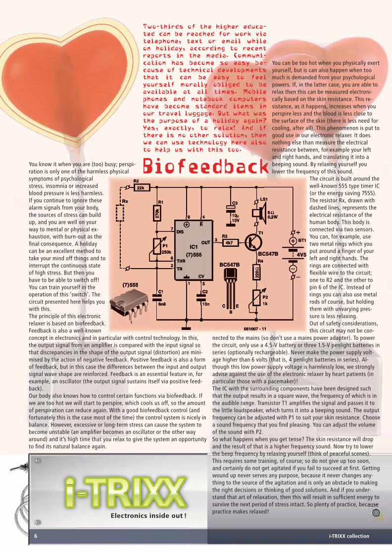
You know it when you are (too) busy; perspi-ration is only one of the harmless physical symptoms of psychological stress, insomnia or increased blood pressure is less harmless. If you continue to ignore these alarm signals from your body, the sources of stress can build up, and you are well on your way to mental or physical ex-haustion, with burn-out as the fi nal consequence. A holiday can be an excellent method to take your mind off things and to interrupt the continuous state of high stress. But then you have to be able to switch off! You can train yourself in the operation of this ‘switch’. The circuit presented here helps you with this.The principle of this electronic relaxer is based on biofeedback. Feedback is also a well-known concept in electronics and in particular with control technology. In this, the output signal from an amplifi er is compared with the input signal so that discrepancies in the shape of the output signal (distortion) are mini-mised by the action of negative feedback. Positive feedback is also a form of feedback, but in this case the differences between the input and output signal wave shape are reinforced. Feedback is an essential feature in, for example, an oscillator (the output signal sustains itself via positive feed-back).Our body also knows how to control certain functions via biofeedback. If we are too hot we will start to perspire, which cools us off, so the amount of perspiration can reduce again. With a good biofeedback control (and fortunately this is the case most of the time) the control system is nicely in balance. However, excessive or long-term stress can cause the system to become unstable (an amplifi er becomes an oscillator or the other way around) and it’s high time that you relax to give the system an opportunity to fi nd its natural balance again.
Two-thirds of the higher educa-
ted can be reached for work via
telephone, text or email while
on holiday, according to recent
reports in the media. Communi-
cation has become so easy be-
cause of technical developments
that it can be easy to feel
yourself morally obliged to be
available at all times. Mobile
phones and notebook computers
have become standard items in
our travel luggage. But what was
the purpose of a holiday again?
Yes, exactly, to relax! And if
there is no other solution, then
we can use technology here also
to help us with this too.
Biofeedback
You can be too hot when you physically exert yourself, but is can also happen when too much is demanded from your psychological powers. If, in the latter case, you are able to relax then this can be measured electroni-cally based on the skin resistance. This re-sistance, as it happens, increases when you perspire less and the blood is less close to the surface of the skin (there is less need for cooling, after all). This phenomenon is put to good use in our electronic relaxer. It does nothing else than measure the electrical resistance between, for example your left and right hands, and translating it into a beeping sound. By relaxing yourself you lower the frequency of this sound.
The circuit is built around the well-known 555 type timer IC (or the energy saving 7555). The resistor Rx, drawn with dashed lines, represents the electrical resistance of the human body. This body is connected via two sensors. You can, for example, use two metal rings which you put around a fi nger of your left and right hands. The rings are connected with fl exible wire to the circuit; one to R2 and the other to pin 6 of the IC. Instead of rings you can also use metal rods of course, but holding them with unvarying pres-sure is less relaxing.Out of safety considerations, this circuit may not be con-
nected to the mains (so don’t use a mains power adapter). To power the circuit, only use a 4.5-V battery or three 1.5-V penlight batteries in series (optionally rechargeable). Never make the power supply volt-age higher than 6 volts (that is, 4 penlight batteries in series). Al-though this low power supply voltage is harmlessly low, we strongly advise against the use of the electronic relaxer by heart patients (in particular those with a pacemaker)!The IC with the surrounding components have been designed such that the output results in a square wave, the frequency of which is in the audible range. Transistor T1 amplifi es the signal and passes it to the little loudspeaker, which turns it into a beeping sound. The output frequency can be adjusted with P1 to suit your skin resistance. Choose a sound frequency that you fi nd pleasing. You can adjust the volume of the sound with P2.So what happens when you get tense? The skin resistance will drop and the result of that is a higher frequency sound. Now try to lower the beep frequency by relaxing yourself (think of peaceful scenes). This requires some training, of course; so do not give up too soon, and certainly do not get agitated if you fail to succeed at fi rst. Getting wound up never serves any purpose, because it never changes any-thing to the source of the agitation and is only an obstacle to making the right decisions or thinking of good solutions. And if you under-stand that art of relaxation, then this will result in suffi cient energy to survive the next period of stress intact. So plenty of practice, because practice makes relaxed!
i-TRIXX collection6
i-TRIXX UK07.indd 6i-TRIXX UK07.indd 6 19-10-2007 12:02:1919-10-2007 12:02:19

Watering house plants on time is not always an easy task for everyone.
The watering can often only appears after the leaves are already looking
a bit sad. Not every plant recovers from such a period of drought. With
a handful of electronic parts and a spare hour you can build yourself an
indicator that will give a timely indication with a fl ashing LED that the
well-being of your house plants is in your hands.
Thirst indicator
for
house plantsAn easy way to determine the moisture of the soil of a pot plant is to measure the electrical conductance of the soil with two electrodes. As the soil dries out, it becomes a poorer conductor between the two electrodes. To prevent electrolysis (decay or corrosion) of the electrodes, a pure AC voltage has to be used. The easiest way to make this AC voltage is to use a gate with a Schmitt trigger input as an oscillator. Here we used a 74HC132 (an IC with 4 NAND gates).An oscillator (also called an astable multivibrator) has been designed around IC1A, the frequency of which is set to about 10 kHz. C1 is charged and discharged via R1, whenever a switching threshold of the Schmitt trigger is crossed and the output of the gate changes logic state. The electrodes are connected via capacitors (C2 and C3) to the output of the oscillator and the input of the second gate (IC1B) to make absolutely sure that the current through the electrodes is pure AC. In this way the soil of the plant conducts the signal from IC1A to IC1B. If the soil is suffi ciently moist, the AC voltage at the second electrode is large enough to switch IC1B at the same rate as that of the oscillator (IC1A). The square wave output voltage of IC1B is rectifi ed by diode D1 and fi ltered by capacitor C4 so that gate IC1C has a high level on both of its inputs and therefore a low level at its output. This low level ensures that the output of gate IC1D remains high and the indicator LED (D3) stays off.IC1D is also wired as an oscillator. This oscillator comes alive (input pin 13 goes high) when the soil is too dry and therefore the AC voltage at the second electrode is too low. The correct level between dry and moist can be adjusted with P1, depending on the type of plant and soil, and the spacing between the electrodes.The frequency of the oscillator built around IC1D is about 1.5 Hz. The result of this is a brightly fl ashing LED. D2 and R7 ensure that the LED is lit for only 20% of the period (and is therefore off for 80% of the time); it is therefore obvious when the LED is on, while at the same time the average current consumption from two 1.5-V batteries is reduced signifi cantly.The current consumption with a fl ashing LED amounts to about 1.4 mA. When the LED is off it is about 0.4 mA. With two penlight batteries the circuit will operate for about 300 days (we assume a capacity of 3000 mAh), provided, of course, that the plants are always watered in good time…
1
23
IC1.A
&4
56
IC1.B
&9
108
IC1.C
&
12
1311
IC1.D
&
C1
100p
C2
10n
C3
10n
C4
220p
R4
270k
R3
220k
R5
1M
R8
390
R6
1M
R7
220k
D1
1N4148
D2
1N4148
R1
1M
C5
163V
D3
R2
47k
100k
P1
IC1
14
7
C6
100n
BT1
1V5
BT2
1V5
IC1 = 74HC132
+3V
74HC132
i-TRIXX collection 7
i-TRIXX UK07.indd 7i-TRIXX UK07.indd 7 19-10-2007 12:02:5019-10-2007 12:02:50

Electronics inside out !Electronics inside out !
Has a channel from your ste-
reo failed, or you don’t hear
anything anymore from your
headphones from your MP3
player? It could be a broken wire or a bad
plug, but also the internal electronics could
have given up the ghost. With this test bee-
per you can quickly fi nd out.
The test beeper presented here generates a sinusoidal signal with a frequency of 1,000 Hz, a common test frequency for audio amplifi ers. The test signal can be directly connected to the input of an amplifi er or via the suspect cable. You can then wiggle cables and plugs in an attempt to locate a potentially bad connection. Swapping cables around sometimes helps as well. The test beeper can also be used as a signal injector when looking for faults in amplifi er stages. For this you ‘inject’ a test signal, for example starting at the input, directly into the amplifi er and progressively move the injection point towards the output until the test signal becomes audible; the location of doom is quickly found in this way. If you are going to use the test beeper as a signal injector then it is recommenced (to prevent a potential overload of the electronics to be tested) to connect a resistor of at least 10 kohm in series with the output.
The test beeper consists of a classic Wien-Bridge oscillator (also known as a Wien-Robinson oscillator). The network that determines the frequency consists here of a series connection of a resistor and capacitor (R1/C1) and a parallel connection (R2/C2), where the values of the resistors and capacitors are equal. This network behaves, at the oscillator frequency (1 kHz in this case), as two pure resistors. The opamp (IC1) ensures that the attenuation of the network (3 times) is compensated for. In principle, a gain of 3 times should have been suffi cient to sustain the oscillation, but that is in theory. Because of tolerances in the values, the amplifi cation needs to be (automatically) adjusted.Instead of an intelligent amplitude controller we went for a somewhat simpler solution. With P1, R3 and R4 you can adjust the gain to the point that oscillation just takes place. The range of P1 (±10%) is large enough to cover the tolerance range. To sustain the oscillation, a gain of slightly more than 3 times is required, which would, however, cause the amplifi er to clip (the ‘round-trip’ signal becomes increasingly larger, after all). To prevent this from happening, a resistor in series with two anti-parallel diodes (D1 and D2) are connected in parallel with the feedback (P1 and R3). If the voltage increases to the point where the threshold voltage of the diodes is exceeded, then these will start to conduct slowly. The consequence of this is that the total resistance of the feedback is reduced and with it, the amplitude of the signal. So D1 and D2 provide a stabilising function.The distortion of this simple oscillator is around 0.1% after adjustment of P1 and at an output voltage of 100 mV (P2 to maximum). You can adjust the amplitude of the output signal with P2 as required for the application. The circuit is powered from a 9-V battery. Because of the low current consumption of only 2 mA the circuit will provide many hours of service.
Test beeper for your
stereo system
i-TRIXX collection8
C
1
3V...15V
i-TRIXX UK07.indd 8i-TRIXX UK07.indd 8 19-10-2007 12:03:0119-10-2007 12:03:01

You can, of course, reduce the output from a torch by connecting a resistor in series with the lamp. If you select resistors with several differ-ent values you can adjust the brightness of the lamp in several steps. Such a control does not make particularly effi cient use of the (recharge-able) batteries in the the torch; after all, a considerable amount of electrical energy in the form of heat is wasted in the series resistor. In particular when we, as campers, choose to pitch our tent far from the civilised world (and power points), we obviously have to be as frugal as possible with the limited energy in the batteries of our torch. This is easily done with a little electronics.
Ordinary mains light dimmers also use as little energy as possible. Not only to prevent the waste of energy but also to limit the heat gen-erated by the dimmer itself. The latter is very important when dimming incandescent lamps connected to the mains, if we would like to avoid scorched wallpaper. The ubiquitous light dimmer for incandescent lamps regulates according to the on/off principle. The mains voltage is passed completely for part of the time and blocked completely for another part. This happens at the same rate as the frequency of the mains. In this type of control there is (nearly) no electrical energy lost in the form of heat.
We can also make such a low-loss on/off con-trol for the DC (= battery voltage) powered torch. The controller ensures that the battery voltage is switched on and off at such a high rate that it appears to the eye that the lamp is on continuously. The lamp itself, because of the fi lament’s slow reaction, also contributes to averaging of the on/off switching. By varying the ratio between the ‘on time’ and ‘off time’ we control the amount of light from the lamp in an energy effi cient way.
For the fast on/off switch we use the familiar timer IC type 555. Specifi cally the CMOS ver-sion of the original NE555 is used, called TLC555 because this version uses less current. Even though this IC has a lower output current rating this is not a problem here, because an additional output transistor is used (in this case a FET) to drive the lamp. A BS170 was chosen for this transistor, which can deal with a lamp current of 500 mA without any problems. For larger applications you will have to use a real power MOSFET such as a BUZ11 or similar. With these make sure that the battery voltage is suffi cient to ensure that the MOSFET is turned on properly; some types may require more than 4 V on their gate!The 555 is confi gured here as a squarewave oscillator. A squarewave-shaped voltage ap-pears at the output (pin 3). Differing from the standard application is the addition of diode D1. Because of D1, two different times can now be adjusted independently. The amount of time that the output is logic High is determined by R1 and C1 and amounts to about 0.8 ms. The time the output is low is determined by R2, P1 and C1 and can be adjusted with potentiometer to a value between 1.9 ms and 36 μs. The duty cycle (the ratio between on and off) can be adjusted from 30% to 96% with these part values. Dimming to less than 30% has little merit because the light output will be too low to be useful in practice.The operating principle of the circuit also causes the frequency to vary. At 30% the frequency is about 370 Hz and at 96% about 1.2 kHz. But that doesn’t matter of course, both for an incandescent lamp and our eyes.The circuit is obviously powered from the bat-teries in the torch. Without a lamp the circuit, at a battery voltage of 6 V, consumes only 170 μA and at 12 V, about 280 μA. (If an NE555 were used instead of a TLC555 this current consumption would be considerably higher!) The low current consumption of the circuit itself can be neglected compared to the current con-sumption of the lamp and the circuit therefore
has practically no infl uence on the life of the batteries. The fact that the maximum setting is only 96% has the pleasant side-effect that the lamp will have a much longer life expectancy.
To test the circuit we used a lamp rated at 6 V/50 mA. At full brightness the voltage across the lamp was 5.66 V and current was 49.5 mA. At minimum brightness this voltage was 1.71 V with a current of 19.6 mA. Both the measured voltages are a little lower than expected from the duty cycle, but don’t forget that T1 is not an ideal switch and a small voltage is lost across it.
First build the circuit on a piece of prototyping board (experimenting PCB) and connect the lamp from the torch by itself. Only build the dimmer into the torch when everything works properly! First trace the connections from the batteries to the lamp and on/off switch. Be-cause it is usual for the switch and/or the lamp holder to be permanently connected with ground (the electrically conducting metal hous-ing of the torch) it can be a bit of a puzzle to obtain the correct connections with the switch. It is easier of you fi t a separate miniature on/off switch in the housing for the torch and connect it in series with the batteries with two separate wires. Use a small piece of double-sided PCB that you place between the battery and the ground spring (if there is more than one battery in the torch you can place the PCB between two batteries; it doesn’t matter between which, as long as it ends up in series with the batteries). Solder the wires to each of the copper surfaces (i.e. those that are electrically separated from each other). Both wires are now connected to the new on/off switch. Now connect the lamp from the torch to the circuit. Make sure there are no electrical connections between the lamp holder and the other parts of the torch (change the mounting of this holder if necessary) and connect the lamp with two wires to transistor T1 and the positive of the battery (or the series connected batteries).Use a miniature version for the potentiometer (P1) and mount it in a convenient place and connect this to the circuit with two wires as well. Once you’ve connected everything cor-rectly you can adjust the light output from the torch between mood light and search light.
Light dimmer for torches
i-TRIXX collection 9
TLC555
IC1
DIS
THR
OUT
TR
CV
2
7
6
4
R
3
5
8
1
R1
100k
R2
4k7
P1
250k
D1
BAT85
C1
10n
C3
100n
C2
100n
T1
BS170
LA1
3V...15V
V
061010 - 11
BS170
DG
S
TLC555
Light dimmers these days are not a curiosit
y anymore; every home improvement store, W
all-
Mart or B&Q has at least a few models on
their shelves. A light dimmer for a torc
h, ho-
wever, is something that you will not fi nd
all that quickly. Such a controller can nev
ert-
heless be very handy: a battery-saving, dim
med light when reading or for mood-lightin
g in
a tent when camping, or maximum light outp
ut when required. And if such an energy-sa
ving
light dimmer cannot be bought, then why do
n’t we just build one ourselves?
i-TRIXX UK07.indd 9i-TRIXX UK07.indd 9 19-10-2007 12:03:1919-10-2007 12:03:19

Electronics inside out !
LEDs show the way
To indicate direction you could obviously just use an illuminated arrow or a fl ashing light, but it is much nicer of course if something moves in the correct direction. The idea, here developed into a circuit, was born when we saw and older circuit with a few LEDs in the shape of an arrow. The LEDs were driven as a running light with two ICs; a clock generator and a shift register. We immediately thought that this was a nice idea, but it should be simpler than that. And that that is indeed possible is shown by this circuit. Only three inverters with Schmitt-trigger inputs are used. That is only half of a 74HC14. The other three inverters (IC1D to IC1F) are, to prevent noise on open inputs, connected to fi xed input voltages by connecting them in series with the fi rst input connected to the power supply voltage. The inverters behave as level-changing switches (a High level appears on the output as a Low level), while the Schmitt-trigger behaviour ensures a clean switching transition.The clock signal (the pacemaker for the running effect) is, just as with a standard oscillator, generated with a Schmitt-trigger inverter (IC1A), but instead of feeding back its own output, feedback is now connected to the output of the third (IC1C) of the three in series connected inverters. The output signal used for the feedback signal has the be of opposite phase, of course.Six series connections of three LEDs each (arranged in the shape of arrows) are connected to the outputs, or more accurately, between the outputs of the inverters in such a way that only two of the six columns (arrow points) are lit with two extinguished columns in between. Each time the lit arrows move over by one column, so that it appears that the arrows run from right to left.
To make the arrow longer than the six columns drawn in the schematic, the additional columns are connected in the same order as the fi rst. So the seventh column is connected in parallel with the fi rst column (D16, D17 and D18), the eighth column in parallel with the second column (D13, D14 and D15), etc. Keep the number of columns limited to 15; more columns are too high a load for the inverters.
Once the circuit has been built, you can experiment with the clock speed if you like.
This has an infl uence in the perception of the running effect. With a slightly shorter
time (lower value for C1 to C3 or R1 to R3) the circuit appears to become a collection of
fl ashing LEDs. Depending on your personal preference, another timing may be required.
Build the circuit with red LEDs of the high-effi ciency type. With 9 columns the circuit does not quite draw 6 mA. This is quite easy to calculate, because the current for each column of LEDs is set to just under 2 mA, and 3 columns are turned on each time. If only 8 columns are connected then the average current consumption will be a little lower. The low current consumption of the circuit makes it possible to power it from batteries. Recent alkaline AA batteries often have a capacity of 2800 mAh. With four AA batteries in series (and therefore generate a power supply voltage of 6 V) the circuit will run continuously for nearly 20 days. In a permanent installation a modern switch-mode mains adaptor is preferable for the power supply.
D1
D2
D3
R4
47
0Ω
R1
1M
R2
1M
D4
D5
D6
R5
47
0Ω
D7
D8
D9
R6
47
0Ω
D10
D11
D12
R7
47
0Ω
D13
D14
D15
R8
47
0Ω
D16
D17
D18
R9
47
0Ω
1 21
IC1.A
3 41
IC1.BR3
1M5 6
1
IC1.C
C1
220n
C3
220n
C2
220n
+6V
C4
100n
13
12
1
IC1.F
11
10
1
IC1.E
9
8
1
IC1.D
+6V
IC1
14
7
6V
061011 - 11
IC1 = 74HC14
i-TRIXX collection10
In dark places in particular, an illuminate
d direction indicator can be a handy
aid. We’re not referring to the turn indica
tors on your car, motorbike or scooter,
but merely an illuminated sign that, for e
xample, directs you to the exit of a
building. With only one IC, 18 LEDs and a f
ew resistors and capacitors you can
build a prominent indicator that shows the correct di
rection in the form of
running LED arrows. In this way no one will miss the doo
r to your house party,
and afterwards, the outside door.
i-TRIXX UK07.indd 10i-TRIXX UK07.indd 10 19-10-2007 12:03:2819-10-2007 12:03:28

Electronic Electronic
drummingdrumming
i-TRIXX collection 11
The drum in earlier
times was not only
used as musical
instrument, but
also (if we’re to
believe the ‘Indian
stories’...) as a
communications
device to transfer
messages quickly
over large distanc-
es. Such communi-
cations go much
simpler these days;
you don’t have to
follow a diffi cult
course in ‘message
drumming’ and in
addition you can
send your message
(if the servers de-
cide to co-operate
a little) around
the world in mere
moments, sometimes
to the annoyance of
those who didn’t
ask for it. In the
current electronic
age an electronic
drum is more ap-
propriate, not as
a communication
device any more,
but solely as a
musical instrument.
The sound of a drum is generated
when a stick or hand hits a
tightly stretched skin. This skin causes the surrounding air to
vibrate which then sounds like music.
After the strong strike (attack) that brings the skin in motion, the sinusoidal vibration dies away slowly (decay). This wave shape can also be generated elec-tronically by driving a loudspeaker with a suitable cir-cuit. Such a circuit is shown here.
It concerns a simple phase-shift oscillator. This oscil-lator generates a nice sinusoidal signal. The resis-tors R1, R2 and R3, the capacitors C1, C2 and C3 and coupled to this network the resistors R4 (when S1 is pressed) and R5 and capacitor C4 ensure that the si-nusoidal signal at the collector of T1 is changed in phase by exactly 180° and gets fed back to the base of T1. The signal at the collector is again phase shifted by 180° with respect to the base voltage so that the total phase shift is 0° and the circuit will oscillate when there is suffi cient gain (which is the case here).
When you press push button S1, the oscillator gener-ates a continuous sinusoidal signal, provided the gain is set correctly with P1. This gain has to be just right so that the oscillator just continuous to oscillate and does not decay. When S1 is released the oscillator will stop. Checking the oscillator is obviously the easiest (that is, without measuring instruments) by connect-ing the output to the input of your sound system. Take into account the fact that the circuit has an output signal of several volts, so start by setting the volume of the sound system to a low level (this saves speak-ers and ears).
So, by pressing switch S1 you strike the electronic drum. The pitch is determined by the oscillator fre-quency. With the component values shown in the schematic this frequency is around 240 Hz. Our drum sounds like a marimba that is being played with soft
sticks. If you would like to change the frequency and therefore the sound of the drum you need to change the values of C1, C2 and C3 up or down by the same ratio (higher values result in a lower frequency).You can also experiment with the value of capacitor C4 and resistor R4. For a slower decay, increase C4 and reduce R4 in the same proportion. When R4 is ratiometrically reduced even further this increases the attack of the oscillator and changes the sound to more that of a drum. Don’t forget to adjust the gain again to its optimum setting.
The electronic drum draws about 4 mA of power supply current whenever it is struck. When S1 is not pressed the circuit draws practically no current: a sep-arate on/off switch is therefore not necessary. You can use a 9-V battery for the power supply.
In the accompanying photograph you can see a piece of prototyping board we used the build the electronic drum. At the bottom left of the board you can see two sockets; this makes experimenting with different resistor or capacitor values much easier than repeat-edly soldering and de-soldering!
If you would like to build multiple drums of differ-ent pitch, then you obviously need a correspondingly larger circuit board. Positions the switches, for exam-ple, in such a way you can play them without moving your hand. Use microswitches that require a low force to operate and if necessary glue a larger striking sur-face to each switch.
i-TRIXX UK07.indd 11i-TRIXX UK07.indd 11 19-10-2007 12:03:5519-10-2007 12:03:55

Electronics inside out !
Time for a game?
“Your time starts now!” This is a phrase that is often heard preceding a
contestant’s turn in an exciting game show. An electronic timer serves as an
aid to give each player an equal chance. With some games played around the
table at home, such a timer can also avoid heated arguments. An i-TRIXX reader
who apparently was keen to maintain good relations within his family asked us
for a design of an easy to build game timer. Our Elektor lab got busy.
The reader asked for a timer to be used with the game Rum-mikub. The circuit has to give some sort of indication when 1 or 2 minutes have elapsed. We started with this design brief, but the circuit is easily adapted if different times are required.
For the heart of this circuit we chose an IC that has been used in earlier i-TRIXX circuits, the type 4060. This IC makes it easy to generate extremely long times that can be set accurately. An LED (D2, a low-current type) is used to indicate that the timer is running and the power is switched on. A buzzer (BZ1) sounds when the game time is over.
Just a short explanation about the operation of the IC, a so-called binary counter with an internal clock oscillator. At its CT outputs there is a digital pattern of zeros and ones. At fi rst all outputs are zero. It then runs through all the digital coun-ter values (and that are quite a few with this 14-bit counter, 16,384 to be exact). This happens at a rate set by the RC net-work connected to pins 9 to 11. Since the indicator LED (D2) is connected to the internal clock oscillator, it fl ashes at the same rate of about 4 Hz. The way the IC is used in this circuit, the
counter will not reach its maximum value. When the switch S2 is in the ‘2 minutes’ position, the counter will stop itself (via diode D1) the moment that output CT9 becomes high (logic 1). At the same time, transistor T1 (which serves as a buffer) will activate the buzzer. That obviously happens exactly 2 minutes after pressing the start button (S1). If switch S2 is in the other position then the buzzer will sound after 1 minute. Should the time not be quite right then it can be accurately adjusted with potentiometer P1 and comparing it with a stopwatch or the seconds hand of a clock or watch.
We deliberately kept the circuit as simple as possible (no ad-ditional power-on-reset network). So it is possible that when the circuit is fi rst switched on, some arbitrary time between 0 and 1 or 2 minutes will elapse before the buzzer sounds. How-ever, after pressing the start button (reset) the timer will run for the correct length of time. Incidentally, the length of time that the start button is held down has no infl uence on the selected time.If you would like to be able to stop the timer before the time is up you can consider connecting S1 with the positive power supply instead of pin 12 of the IC. The counter will now be reset whenever S2 is pressed. Once you release the button the timer starts to run.
Besides Rummikub, the timer can of course be used with other games and applications that require an indication after a prede-termined amount of time. The time can be shortened by a factor of 2 to half a minute by connecting output CT7 (pin 14) instead of output CT8; or lengthened by a factor of 4 from 2 minutes to 8 minutes by connecting output CT11 (pin 1) instead of out-put CT9 to switch S2. Note that the IC does not have an output CT10; lengthening the time from 2 to 4 minutes (factor of 2) is therefore not possible. If you need that length of time, then it is necessary to double the value of resistor R1 or capacitor C1. If you would like more than two different timer values then you can substitute a switch with more positions for S2 and connect its contacts to the desired CT outputs.
The current consumption of the timer – when running – is de-termined mainly by the fl ashing LED and mounts to less than 1 mA. The current consumption is obviously considerably high-er when the buzzer is on. With the prototype we built, it was about 16 mA. For the beeper (buzzer) we used a round, axial, 12-V version.
i-TRIXX collection12
50k
P1
CTR14
4060
IC1
CT=0
RCX10
11
12
15
13
14
11
13
12
CTCX
RX
!G
16
1
6
4
5
7
9
3
4
5
6
7
8
9
3
2
+
8
R1
82k
R2
1M
C1
1μ
R3
3k9
D2
D2
R4
10k
S2
D1
1N4148
S1
1 min.
2 min.
T1
BC547B
BZ1
12V
C2
100n
S3
BT1
9V
+9V
BC547B
CB
E
061012 - 114060
K
K
A
A
i-TRIXX UK07.indd 12i-TRIXX UK07.indd 12 19-10-2007 12:04:3619-10-2007 12:04:36

Order quickly and safe through
www.elektor.com/shop
• A complete solution: robot + software + curriculum
• Line following and maze solving
• High-tech specifi cations
• Also programmable with C or ASM
• E-blocks compatible
• Motivating for education and hobby
Formula Flowcode BuggyUSB-programmable robot vehicle (incl. CD-ROM)
Ready
to use
for only £85.00US$ 169.00
electronics worldwide
Elektor
Regus Brentford
1000 Great West Road
Brentford TW8 9HH
United Kingdom
Tel. +44 20 8261 4509
ELEK UK advo itrixx.indd Sec1:7ELEK UK advo itrixx.indd Sec1:7 26-10-2007 10:12:0826-10-2007 10:12:08

Electronics inside out !
Chip-canary
i-TRIXX collection14
The silicon canary described here (Serinus canarius siliconis) is fed with batteries. An empty battery just means that the cheerful chirping stops; a fresh specimen will bring it back to ‘life’. In this way feelings of guilt on the part of the owner are avoided.
The heart of this canary is formed by a chip, or more specifi cally, an IC type 4093, a quad NAND-Schmitt-trigger. This IC has already been used in other i-TRIXX circuits. With NAND-gates you can very easily build different types of oscillators. That is the case here as well.
Birds have a syrinx at the lower part of their throat, a vocal organ whose shape is changed by muscles and in this way produces different sounds. The syrinx is here emulated with three oscillators, built around gates IC1.A, -B and -D. Each oscillator provides its own part of the canary song. The individual oscillator wave shapes are combined by the surrounding components and produces an output signal that, when acoustically reproduced by piezo buzzer (Bz1), sounds quite similar to the cheerful chirping of a real, live canary. The oscillators obviously have to be properly tuned by ear fi rst. Adjust potentiometers P2, P3 and P4 so the song from the chip-canary best resembles a real one. With three presets it takes a little while to obtain the closest true-to-life setting. P4 is used to move the entire frequency range up or down. P2 and P3 are then adjusted so that a realistic chirping can be heard.
The get this electronic canary to sing, it is enough to push switch S2. Depending on the setting of potentiometer P1 he will sing for a certain amount of time. Feed this canary with a 9-volt battery. To prevent the canary from eating the whole battery, you can turn the power supply voltage off with S1.
Pets are nice; they provide pleasant companionship. Especially for those living alone,
and those in nursing homes, a pet can provide a welcome relief from the mundane of
daily routine. It is less pleasant when pets die, not a single specimen exempted. They
tend to do that sooner if they’re not looked after. Forgotten to feed the dog or the
cat? Oh, they will defi nitely let you know, but the canary will sit there quietly until he
drops off his perch. The chip-canary, built from electronics, will be spared this grief.
BC547CBC549C
CB
E
8
910
IC1.C
&5
64
IC1.B
&12
1311
IC1.D
&
1
23
IC1.A
&
R1
100k
R4
1k
R5
470k
R3
68k
1M
P1
500k
100k
P2
P3
500k
P4
D4
D2
D3
D5
D1
1N4148
C1
22μ10V
C2
2μ210V
C3
1μ10V
C5
10μ10V
C4
2n2
R2
100k
T1
BC547C
R6
10M
IC1
14
7
BC549C BZ1
PB2720
S1
S2
4093
1N41484x
070052 - 11
+9V
BC547CBC549C
CB
E
8
910
IC1.C
&5
64
IC1.B
&12
1311
IC1.D
&
1
23
IC1.A
&
R1
100k
R4
1k
R5
470k
R3
68k
1M
P1
500k
100k
P2
P3
500k
P4
D4
D2
D3
D5
D1
1N4148
C1
22μ10V
C2
2μ210V
C3
1μ10V
C5
10μ10V
C4
2n2
R2
100k
T1
BC547C
R6
10M
IC1
14
7
BC549C BZ1
PB2720
S1
S2
4093
1N41484x
070052 - 11
+9V
i-TRIXX UK07.indd 14i-TRIXX UK07.indd 14 19-10-2007 12:05:1119-10-2007 12:05:11

i-TRIXX collection
When playing this game you literally have to become a contortionist. The skill is to move the ring as quickly as possible along the twisted wire from beginning to end. The ring is obviously not allowed to touch the wire along its path, because this is punished immediately with the sound of the buzzer to indicate that you have forfeited your turn. Dawdling too much will also end you attempt.
We have attempted to keep the electronic part of the game as simple as possible. So we haven’t used, for example, and on/off switch; in the idle state the current consumption is negligibly small. The circuit comes alive when pressing the start button (S1).
The circuit consists of only one IC (a 4538) that contains two timers. The fi rst timer (IC1A) drives the buzzer for a limited amount of time, so that it does not continue to beep unnecessarily and irritate other players and spectators. We choose a duration of 10 seconds. This also reduces the current consumption of the circuit and since the power supply is provided by a 9-V battery this is a nice benefi t. Because the outputs from the IC cannot deliver suffi cient current to drive the buzzer directly, T1 is connected to the output of IC1A to act as a buffer.
The second timer IC2B determines to amount of time allotted to carry out your task. This time can be adjusted from 22 seconds to 2 minutes with the aid of P1. An LED (D1) is lit for the duration of your turn.The timing durations for both the fi rst as well as the second timer are easily changed to suit your needs. The duration is determined by and RC network connected to pins 1 and 2 of IC1A and pins 14 and 15 of IC1B. The length of time that the outputs of the timers are active is equal to R x C. For example, for IC1A the time is: 1 MΩ x 10 μF = 1 x 106 x 10 x 10-6 = 10 seconds.
It is as easy as that! Always use good quality electrolytic capacitors (that means high leakage resistance) for C1 and C2.
The sensor (the ring) is connected to the positive trigger input (pin 4) of the fi rst timer. Output pin 6 of the fi rst timer goes High (= 9 volts) when pin 4 goes from Low (= 0 volts) to High, that is, when the ring touches the wire. The buzzer is driven via T1 and sounds the signal that the ‘attempt has failed’. Pin 5 of this timer works the other way around; a low level starts the buzzer. This is used to drive the buzzer (the LED turns off) when the maximum game time (pin 10 of IC1B goes low) has elapsed. When you press S1, the fi rst timer is reset and the second timer is started. Pin 6 of IC1A is now low and pin 10 of IC1B is high, with the result that the buzzer is silent and LED D1 is lit to indicate that the game is in progress. If the game time elapses before the player has reached the fi nish line, then the second timer will activate the buzzer and turn the LED off.If the fi nish is reached within the allotted time, it is not necessary to wait until the time is up to start a new game. As soon as S1 is pressed the timers are back at their initial positions and a new game has started.The circuit draws practically no current when the LED and buzzer are off. We measured less than
0.4 μA. With only the LED on the current consumption amounts to slightly less than 2 mA. When the buzzer is activate and the sensor is connected with the wire (9 V) the current consump-tion is the greatest and that was a little over 17 mA in our prototype. We used a low-cur-rent type for the LED, which is quite bright at only 2 mA. The minimum voltage is mainly determined by the buzzer and our prototype continued to work when the power supply
voltage was down to 4.4 V! The LED, however, was only dimly lit. To save on battery power it is possible to shorten the amount of time that the buzzer is on some more.It is best to build the circuit into the enclosure that also supports the twisted metal wire. The beginning (start) and end (fi nish) of the wire is fi tted with a small amount of insu-lation (electrical tape or sleeving, for example); the ring can then be parked without activating the circuit. Internally you connect the twisted wire with the positive terminal
of the battery (which is also connected to the circuit). The metal ring is con-nected with a fl exible (insulated) wire to the sensor input of the circuit (pin 4 of IC1A). Now you can check whether you possess a steady hand and nerves of steel.
Nervous spiral
Nervous spiralNervous sp
Nervous spiralNervous sWho hasn’t seen one of these, or perhaps in this century we should ask: who
still has one of these, that nerve-racking but exciting game where you have
to move a metal ring along a twisted, metal wire to an endpoint without
the two making electrical contact with each other? This requires a steady
hand and nerves of steel. i-TRIXX helps you build an electronic referee
for this game, which not only verifi es whether the fi nish line has been
reached, but also places a time limit on the duration of the game.
15
START FINISHFINISHSensor
061015 - 12
IC1.A
2
RCX
1
CX
4
3
R
6
7
5
≥1
IC1.B
14
RCX
15
CX
12
13
R
10
9
11
≥1
T1
BC
BZ1
12V
R3
100k
S1R1
10k
R2
1M
R4
220k
R5
3k9
D1
STA T
C110μ63V
C2100μ25V
1M
P1
547B
BT1
9V
IC1
16
8
C3
100n
+9V
+9V
BC547B
CB
E
Se sor
061015 - 11
IC1 = 4538
i-TRIXX UK07.indd 15i-TRIXX UK07.indd 15 19-10-2007 12:05:4219-10-2007 12:05:42

Electronics inside out !
Tent alarmIt is quite diffi cult these days to protect a house from unwel-
come guests, not to mention a tent! However, with a little bit
of electronics it is possible to protect a tent reasonably well.
It is of course not possible to completely prevent someone
from breaking into a tent with an electronic tent alarm, but
at least you and the other
camping guests will be made
aware when someone is in
the process of wrong-
fully appropriating
other people’s prop-
erty. Such a tent
alarm is, of
course, also
handy when
camping in, for
example, the
North-Ameri-
can wilder-
ness to
prevent a
grizzly
from
joining
you un-
noticed
in your
sleep-
ing
bag.
12
1311
IC1.D
&
9
810
IC1.C
&
1
23
IC1.A
&
5
64
IC1.B
&
R2
10k100k
P1
R3
10k100k
P2
C1
6n8
C2
22μ16V
BZ1
PB2720
R1
100k
A
B
IC114
7
BT1
6V
S1
IC1 = 4093
061017 - 11
4093
i-TRIXX collection16
The alarm
described here is triggered
when a wire is cut or broken. This wire
is connected to the circuit at points A and B (see
schematic).
The circuit itself is built around a single digital IC, type 4093. This
IC contains a set of four NAND gates (IC1.A to D). The characteristic of
such a NAND gate is that the output is only ‘logic 0’ (= 0 volts) when both(!)
of the inputs are ‘logic 1’ (= power supply voltage); in all other cases the output
is always ‘logic 1’. Using that property, two square wave oscillators are built around
gates IC1.C and IC1.D. The task of these two oscillators is to generate an interrupted
beeping sound.
We explain the operation of the oscillator using gate IC1.D. When the alarm is armed with
switch S1, the still intact and electrically conducting wire ensures that point A which is connected to
pin 12 of gate IC1.D is at a ‘logic 0’ level (= 0 volts). As a result the output of this gate stays at ‘logic
1’. This output will charge capacitor C1 (after a short while) via resistor R2 and trimpot P1 to a ‘logic 1’
level. The other input (pin 13) is thus at a ‘logic 1’ level. Nothing else happens.
This state changes when the wire is interrupted. The input at pin 12 will become ‘logic 1’ because of resistor
R1. Now both inputs of this NAND-gate are ‘logic 1’ with the consequence that the output toggles to ‘logic 0’.
The output will therefore discharge capacitor C1 which causes the input at pin 13 to go below the ‘logic1’ level
after a short time. (The Schmitt trigger characteristic of this type of NAND-gate ensures that the transition from ‘1’ to
‘0’ occurs without hesitation. Without this built-in characteristic there could be an undefi ned situation halfway, which
means that faultless operation is not guaranteed.) Since one of the two gate inputs is no longer at ‘logic 1’, the output at
pin 11 changes from ‘0’ to ‘1’. Capacitor C1 is charged again and the whole process repeats itself. The output pin 11 now
rapidly toggles between High and Low levels: we have a square wave.
A similar square wave oscillator is built around gate IC1.C. Because of the higher value of capacitance of capacitor C2
this produces a square wave with a much lower frequency. Both square waves are combined in gate IC1.A. The buzzer (Bz)
connected to the output (pin 3) of this gate now sounds an interrupted beeping noise: alarm!
The remaining fourth gate (IC1.B) of the IC is used for a nice technical trick. This gate delivers an inverted version of the
output signal of gate IC1.A to the other side of the buzzer. The result is a doubling of the sound volume because the membrane of
the buzzer now moves in the positive as well as the negative direction from its rest position. Without this trick the membrane would
only move in either the positive or negative direction (depending on the polarity).
Now how to use the tent alarm in practice. Build the circuit on a piece of prototyping board and fi t it complete with batteries in a
‘camping-proof’ enclosure. Make sure that the buzzer (a type suitable for 6 volts AC, for example the PB2720 made by Toko) can deliver
its sound unimpeded to its environment. Adjust the frequency of the beeper with P1 so that its sounds the loudest. Adjust preset P2
according to your own liking.
Use a thin piece of insulated wire for the ‘guard wire’. Connect one side of this wire to the circuit via a small plug and socket. The
other side is directly connected to the circuit. The wire can now be woven through the tabs of the closed zips of the tent entrance. If the
plug does not fi t through the hole in the tabs you can attach (key)rings to them. If the zip is now forcefully opened then either the plug and
socket will come apart or the wire will break. In either case the alarm will sound.
If you would also like to keep grizzlies out of your tent then it is a good idea to protect more than the offi cial entry into the tent. In this case
you could stretch the thin wire around your tent with the aid of a few
tent pegs. Position the wire far enough from your tent so that
in the event of an alarm you have enough time to fl ee up a tree...
i-TRIXX UK07.indd 16i-TRIXX UK07.indd 16 19-10-2007 12:06:0719-10-2007 12:06:07

i-TRIXX collection 17
Silent dogSilent dog
Canis lupus familiaris, the dog that is, possesses excel-lent hearing. Even though you may not suspect that when Fido,
at the displeasure of his ‘master’ and amusement of bystanders, be-haves as if he doesn’t hear a thing. “Fido here, HEEEERE... Bad dog, come here immediately!” None of it helps, Fido pretends to be deaf. Of course he hears his master call and plead, he just doesn’t listen. During those moments some dog owners doubt the good ears of their unfaith-ful companion and try with abnormally raised voice to get the message across, with little result. It all has to do with the fact that the owner often does not understand that the dog does not comprehend spoken words. A dog, any dog, does not understand spoken language, any lan-guage. Words and their underlying meaning are wasted on the dog. He is better at dealing with clearly separate sounds and particularly when they are heard in the same (preferably happy) circumstances. Whistle to the dog and immediately give him a dog treat. After a few goes (depending on breed and individual) he will walk towards you when he hears you whistling. After a while you omit the treat, of course, other-wise Fido won’t be able to walk because of obesity.It is important that we always sound the same whistle. If we suddenly let Beethoven’s ninth symphony pass our lips then there is a good chance that Fido will look at us with incomprehension. With the dog whistle described here we can consistently generate the same sound. In addition, the circuit produces an ultrasonic tone which is not audible to humans but which a dog can hear. In this way ‘calling’ Fido is not noticed by others. The circuit also makes a suffi cient racket to be able to call the dog back from a large distance.
The electronic dog whistle shown in the schematic consists of a piezo-tweeter (LS1, a high frequency speaker that can reproduce frequencies higher than 20 kHz), which is driven by a so-called bridge circuit. The bridge circuit actually consists of two switching stages, namely T1 and T2 on one side, and T3 and T4 on the other side. The switching behaviour is each other’s mirror image (inverted with respect to each other). When the output signal on the left half is high (T1 conducts and T2 blocks) then the right half is low (T3 blocks and T4 conducts) and the other way around. When the bridge circuit is driven with a square wave, the full power supply voltage as applied across the tweeter, which alternates at the frequency of the square wave. The output vol-ume is doubled because of this reversal. That is because the membrane in the buzzer moves both inwards and outwards from it rest position. Without this trick the membrane would move in only one direction (depending on the polarity), either inwards or outwards.
The bridge circuit is driven by the square wave oscillator built around gates IC1.A to IC1.C. The frequency of this square wave is above the human threshold of hearing and is determined by the RC-network P1/R1/C2. The left switching stage (T1/T2) is driven directly by this oscil-lator and the other stage via the, as buffer and inverter functioning, parallel connected gates IC1.D to IC1.F.
To prevent Fido from being punished unjustly because he does not react to the dog whistle any more while the blame should be placed on the empty battery, we have added a battery indicator in the form of an LED (D1). This LED is lights up only when you press button S1 and the tweeter is driven. This optical indicator is necessary because we can-not, after all, hear the dog whistle. If the LED stays off then we have to replace the battery (and not the dog).
Build the circuit on a piece of prototyping board. For the power supply use a 9-V (rechargeable) battery. Suitable tweeters are, for example, types KSN 1001A or KSN 1005A.You need to test the circuit before you can use it. Turn potentiometer P1 so that you can hear the whistle (if need be, increase the value of C2). You now know that the circuit generates sound. Obviously LED D1 should light up as well. Now turn P1 so that the sound becomes inau-dible. If you are still young and don’t have disco-ears, you may assume that other people won’t be able to hear it either. If you’ve spent too much time in the disco or are not that young any more then ask the help of a young child, because a younger person can still hear high fre-quencies! Adjust P1 in such a way so that a young person cannot hear the whistle more. The dog still has to look up surprised when you press push button S1. This is a sign that everything works properly.Once the circuit is calibrated, the ‘calibration’ of Fido can commence. Don’t hold the dog whistle too close, because the thing produces a lot of noise to his ears. He could run away never to return, and that was not why you built this! Start the training in you back garden (or at one of the neighbour’s if you don’t have one yourself); at least Fido can’t escape this way. When the dog is far enough away, activate only the dog whistle and not your voice. If the dog shows an inclination to come towards you then squat down and encourage him by talking to him with a happy and high pitch voice. Reward him with a dog treat when he walks towards you (never walk to the dog!). Condition this behav-iour by doing it often enough (obviously with rest breaks in between) before taking Fido into the street.
You see the
m, or perhap
s better
expressed, y
ou hear them
: dog owner
s
who decide
at too late
a time to
teach their
(un)faithful
companion
some obedie
nce. They s
cream their
lungs out w
hen Fido has
decided to
run off and,
for the tim
e being,
refuses to
return to i
ts owner. A
nd
why would h
e? Running a
fter other
dogs is mu
ch more fun
, isn’t it?
No,
it is fi rst
necessary t
o teach him
to
return on co
mmand. This
conditionin
g
and respons
e does not n
eed to be
accompanied
with a lot
of scream
ing.
Certainly no
t when usin
g with a, f
or
other people
inaudible,
electronic
dog whistle
. We can bui
ld one with
a
handful of e
lectronic pa
rts.
T1
BD135
T2
BD136
34
1
IC1.B
12
1
IC1.A
56
1
IC1.C
T3
BD135
T4
BD136
1110 1
IC1.E
1312 1
IC1.F
98 1
IC1.D
LS1
piëzo
R1
15k
R2
10k
22k
P1
C2
1n5...2n2
C3
100n
D2
1N4148D1
C1
220μ16V
IC114
7
BT1
9V
S1
061018 - 11
IC1 = 40106
BD135
40106
BD136
B
CE
whistlewhistle
i-TRIXX UK07.indd 17i-TRIXX UK07.indd 17 19-10-2007 12:06:1719-10-2007 12:06:17

Electronics inside out !
If you would like to play CIA- or FBI-agent and subject people to a test of trustworthiness, using elec tro-nics, then you can build yourself a lie detector. An advance warning: doubt the indication of this device before you doubt the honesty of the person concerned, or you will be left with very few friends!
A lie detector does not give reliable results. That is the reason that European judges do not accept the device as evidence in a trial. Nonetheless it is interesting to experiment with one of these and hence the reason we present a simple, make-your-own, lie detector here.The electronic detection of a lie is based on the fact that various physiological reactions can be measured when a person lies. So there are changes (or said in a better way: there may be changes) in blood pressure, breathing, heartbeat, skin temperature and the amount of perspiration when a person adamantly lies The circuit
Lie detector
Do you know the saying
‘Though the lie be swift,
the truth overtakes it’?
If you, based on the wis-
dom of practical experience,
doubt the truth of this
saying, then you place
perhaps more faith in a
lie detector. American
judges do this; they
ac cept the result of a
lie detector test as
supporting evidence.
Fortunately there is a
big stretch of water
between the US and
Europe!
absolute resistance value, it is not suffi cient to make a simple ohmmeter. The circuit fi lters only the change in skin resistance in gives a clear indication on the moving coil meter. The meter (M1) that is used here has a null position in the centre of the scale and can therefore indicate both an increase and a decrease of skin resistance (the scale itself is not important, only the movement of the pointer is relevant).Since the skin has a resistance ranging from a few thousand ohms to several tens of kilo-ohms, the circuit is provided with a high-impedance input amplifi er in the shape of opamp IC1. This opamp drives with its relatively low-impedance output both meter M1 as well as a second opamp (IC2). This second opamp has deliberately been made to react slowly with capacitor C2. Slow changes in skin resistance and therefore also slow changes in output voltage of opamp C1 are fed back through IC2 via R1 and P2 to IC1 with the result that the output voltage of IC1, and therefore also the meter defl ection, hardly changes.On the other hand, a fast change of skin resistance and therefore also the output voltage of IC1 is not compensated by IC2 (C2 effectively shorts-out fast voltage changes), so that the meter (M1) defl ection indicates that the ‘suspect’ is feeling extremely uncomfortable.
presented here measures just the latter reac-tion: a change in sweat production, that is, a change in skin resistance.
The measurement of the skin resistance is done with the aid of two electrodes that are stuck a certain distance apart on the skin of the ‘suspect’. The sensors can be made from, for example, small pieces of circuit board. Solder fl exible wires to the copper
side of the small plates and connect them to the lie detector.
You stick the small plates with the conducting surfaces with bits of
tape to, for example, the underarm. The skin has a certain electrical resistance between the sensors. If the
‘suspect’ feels uncomfortable with the questions asked then he will literally
break into a sweat with a resulting change of skin resistance. This change is sensed by
the lie detector and has to ring alarm bells with you, the questioner. To have any hope of ‘reliable’ results you have to ask simple questions and not something along the lines of:
Is this the fi rst time you have lied today?...
The schematic shows the electronic contents of the build-your-own lie detector. Since we want to measure small changes in skin resistance and not the
LF356
IC1,IC2
R3
3k3
R2
1M
R4
10k
R5
10M
R1
4k7
C1
100n
M1
P1
10k
D2
D1
2x 1N4148
P2
47k
2
3
6
IC17
4
LF356
100 A
i-TRIXX collection18
i-TRIXX UK07.indd 18i-TRIXX UK07.indd 18 19-10-2007 12:06:2619-10-2007 12:06:26

A remark about the meter. As already mentioned it has to be a (panel)meter with a null position in the middle; it has to be able to show a change in skin resistance, after all. The sensitivity of the meter is not very important. If you happen to have another type with a different sensitivity than the 100 μA indicated then you just change the value of resistor R3 accordingly.Don’t use an electrolytic capacitor for C2. This type of capacitor has too high a leakage current for this type of application, which upsets the control system of this circuit. If you are unable to obtain a 1-μF version then you could also use two 470 nF capacitors in parallel.Instead of the in the schematic indicated types for IC1 and IC2 you can also use
any of the following: LF355, TL061, TL071 or TL081.In the interest of safety, the circuit may only be powered with two batteries of
9-volts each (so do not use a mains adapter!). Just to be extra safe, do not stick the sensors so that the heart region is between them. Also do need
stick any sensors on the head. Although the current that fl ows through the skin is very small it is still better to avoid taking any risks. It is best to
attach both sensors, for example, to one arm or one leg.
After the sensors are attached you have to fi rst calibrate the circuit. Slowly (!) turn potentiometer P2 until the meter is in the centre position and indicates zero volts. It can take a while before the measured voltage settles down. The lie detector is calibrated once this is the case. Push a little on a sensor. If the circuit is functioning properly then this will cause the meter needle of meter M1 to move a little. You can adjust the sensitivity of the lie detector to your liking with potentiometer P1. You will, of course, set the sensitivity very low when you are yourself subjected to the lie detector by a friend!
C2
1
2
3
6
IC27
4 BT1
9V
BT2
9V
LF356
10mA
10mA
070211 - 11
Artful LED dimmerTurning an LED only on
and off? That’s a very
meagre use of all the
possibilities that mo-
dern high-effi ciency po-
wer-LEDs of 1 to 3
watts have to offer.
With a low-loss dimmer
you can have a nice
continuous control of
the light output. Take
three power-LEDs of dif-
ferent colour, build
three simple LED-dimmers
and you can create a ma-
gical play of colours.
While such a device is
available ready-made, you
can build one yourself
for much less money
with the benefi t that you
can make it just the way
you want.
For certain applications it would be nice if the brightness of LEDs could be adjusted in a continuous manner. This is particularly true when, for example, you want to mix the colours from
three different coloured LEDs. That can be done with the circuit described here, which you build three times for this application. If you use a slide potentiometer for P1 and position all of them next to each other then you can adjust the brightness by moving them together and change the colour mix by moving them individually.
The circuit (which you have to build three times for the suggested application) is built around the familiar timer IC NE555. Normally, the discharge connection, pin 7, is used, but in this application the time determining capacitor C2 is charged and discharged from the output (pin 3) via R1, P1 and both diodes (D1 and D2). The diodes make it possible to change the pulse/space ratio of the square wave at the output over a wide range from 0.5% to 99.5%. The frequency of the square wave remains quite constant throughout at around 1 kHz. Because of the persistence of vision of our eyes we cannot sense this fast on and off switching of the LEDs and we see a nicely averaged light output.
A MOSFET (T1) is connected to the output of the IC. When this FET is turned on it behaves as a very low resistance and can therefore switch a relatively high current without becoming too warm. It can drive a power LED (D3) with a maximum current of 1 amp without a problem.
i-TRIXX collection 19
i-TRIXX UK07.indd 19i-TRIXX UK07.indd 19 19-10-2007 12:07:0019-10-2007 12:07:00

Electronics inside out !
The circuit described here is not only suitable for refrigerators and freezers, but can also be used to guard other, periodically or continually operating appliances operating from the mains, such as fresh air ventilators, pond pumps, etc. The circuit checks, based on the current drawn by the appliance, whether it is still doing its job or not. If no AC current is detected within an adjustable time period then an acoustic alarm reports that something is wrong.
To detect whether or not current is drawn from the mains by, for example, a freezer, we use the fact that there is a magnetic fi eld around every current carrying wire. In the case of the AC mains this is an AC magnetic fi eld. We pick this fi eld up with a coil of a surplus low voltage relay (we used a 24-volt Siemens relay, type V23027-A0006-A101), which we take apart
until we’re left with only the coil with internal iron core. By winding one of the current carrying wires (either phase or neutral) from the freezer around the core, a voltage is generated in the winding as a result of the electromagnetic fi eld. Without making a dangerous, electrically conducting connection to the mains, we now have obtained a (magnetic) coupling between the freezer and our detector!But it can, and has to be, much safer still, because to be able to wind a conductor around our DIY current sensor we would need to strip the outer insulation from a short section of the freezer power cord. We obviously would leave the insulation of the individual wires (and that are 3 of them, including protective earth, PE) intact. A power cord with its outer sleeving partially removed could not be called safe any more, of course (the insulation is no longer what it was before).
Electrical appliances are expected to work; that is what they’re made
for after all! Technology will however let you down from time to
time. Just one occurrence of water leaking from the freezer it is a
small domestic disaster. An electronic failure detector could have
warned you in time so that you could quickly move the perishable
contents to a neighbour’s freezer. You must of course not wait to
build one of these detectors until the problem presents itself. We
have to build it now!
Failure detector for freezers
Because of its better accuracy and lower power consumption the CMOS type 7555 (or LMC555) is preferred for IC1. Also better are the Schottky diodes indicated in the schematic for diodes D1 and D2. They are only slightly more expensive than ordinary 1N4148, which could also be used.
A suitable power supply is a mains power adapter with regulated output. If the adapter is rated at 1 A, then you can power 3 dimmers with 1-W LEDs, or one dimmer with a 3-W LED. For three dimmers with 3-watt LEDs the mains adapter needs to be rated at least 2.1 A. Remember that the power LEDs need to be cooled. You can, for example, mount them on a length of aluminium angle profi le (see photo).
With the value for R3 shown in the schematic and a power supply voltage of 5 volts, any arbitrary red, yellow or green LED (not power types) with a diameter of 3 or 5 mm (50-milliwatt types) can be connected.The dimmer circuit can be built quite cheaply. The most expensive items are probably the slide potentiometers. You could also use cheap trimpots and adjust the brightness and colour mix of the LEDs in a more permanent way.
The circuit is really a little bit excessive when adjusting the brightness of a single small LED. It is different though when you want to connect multiple power-LEDs in series or create an artful effect with the mixing of colours, as you can see in the photo. This circuit is then much
cheaper compared to devices available ready-made.
The accompanying table is a handy aid when determining the power supply voltage and the value of resistor R3, depending on the number of LED’s (=D3) connected in series.
IC1
DIS
THR
OUT
7555
7555
TR
CV
2
7
6
4
R
3
5
8
1
C3
10n
C2
10n
T1
IRFD024
IRFD024
S
S
D
D
G
G
R2
470 Ω
R1
470 Ω
R3
P1
100k
D1
BAT41
D2
BAT41
C1
10μ25V
UB5...15V
D3
070056 - 11
*
*
IRFD024
i-TRIXX collection20
type red, yellow, green blue, white Power LED Power LED3 + 5 mm 3 + 5 mm 1 W 3 W
UF 1.9 V 3.7 V 3.4 V 3.5 VUB I 25 mA 25 mA 300 mA 700 mA5 V LED s 2 in series 1 1 1
R3 47 - 1/4 W 56 - 1/4 W 5.6 - 1 W 2.2 - 4 W7.5 V LED s 3 in series 1 2 in series 2 in series
R3 82 - 1/4 W 150 - 1/4 W 2.2 - 1 W 0.68 - 1 W9 V LED s 4 in series 2 in series 2 in series 2 in series
R3 56 - 1/4 W 68 - 1/4 W 8.2 - 4 W 2.7 - 4 W12 V LED s 5 in series 3 in series 3 in series 3 in series
R3 100 - 1/4 W 36 - 1/4 W 6.2 - 1 W 2.2 - 4 W15 V LED s 7 in series 3 in series 4 in series 4 in series
R3 68 - 1/4 W 150 - 1/4 W 4.7 - 1 W 1.5 - 4 W
i-TRIXX UK07.indd 20i-TRIXX UK07.indd 20 19-10-2007 12:07:2519-10-2007 12:07:25

RE1 C1
1μ
R2
1M
R3
1k
C3
47μ 25V
2
3
1IC1.A
6
5
7IC1.B
R1
1M
C2
47n
100k
P1
C4
220p
R4
10M
D11N4148
C5
220μ 16V
R6
120k
R5
100k
R7
10M
T1
BC547B
BZ1
12V
C7
100μ25V
C6
100nIC1
8
4
BT1
9V
S1
BC547B
CB
E
*
*
061014 - 11
IC1 = TLC272
TLC272
zie tekst*see text*voir texte*siehe Text*
We solve this problem by using a type of enclosure which is readily available and has a built-in plug and socket (see photo).
We can take the plug of the freezer power cord and plug it into the enclosure and then plug the enclosure into the power point. The enclosure therefore ends up between the mains and the freezer.Each of the three mains connections (phase, neutral and earth) of the plug is connected to the appropriate connection in the socket of the enclosure using appliance wire (2.5 mm2). One of the current carrying wires (not the earth!) is wound once or twice around the relay coil. Be careful that you do not damage the fragile coil winding (perhaps wind some insulation tape around the coil fi rst). The actual current sensor is now fi nished.
The only thing that is now missing, is the circuit that picks up the signal from the sensor and compare the presence of this with a predetermined time. If no current is detected within this time then we have an abnormal situation and the alarm sounds. You can fi nd the circuit in the accompanying schematic. For safety reasons we fi t the entire circuit in the enclosure as well!
RE1 represents the DIY current sensor. The remainder of the circuit is nothing more than an adjustable amplifi er stage (around IC1A) and a voltage comparator (around IC1B). We used only one IC, a TLC272 which contains two opamps (more about that later). To drive the buzzer, a transistor (T1) is also added as a buffer.
To increase the signal level from the coil to a usable level, we chose a maximum gain of about 100. In our case the coil gave a peak voltage of about 17 mV when used with a 100-watt lamp. So this results in a peak voltage after amplifi cation of 1.7 V. This voltage is rectifi ed by diode D1
and fi ltered by capacitor C5 to a smooth DC voltage.
Once the previously detected current disappears and because of the large value of C5 it will take about 30 minutes to one hour before the output of comparator IC1B changes state and raises the alarm with the buzzer. We assume here that a normally operating freezer will turn back on within this time.The guard time depends in the magnitude of the detected mains current, the coil used and the gain set with P1. If need be, the time can be made shorter by lowering the gain. A longer time is obtained by increasing the gain. If that is not enough, then the capacitance of capacitor C5 can be increased. (Use a high quality capacitor for C5.) A longer time is required to ride through the long period of a well-insulated
fridge or freezer when the compressor is off.
The trick is of course the get the circuit to check only whether the compressor of the freezer still runs on a regular basis and doesn’t ‘look’ at any ancillary things such as indicator lamps, interior light and such. To make the circuit less sensitive to small currents it is possible to increase the value of R6 a little, but this has the consequence that the time duration is reduced somewhat.
For the buzzer we again selected a radial, 12-V type for PCB mounting, which still works well at a lower voltage. A pleasant side-effect is that the buzzer also draws less current at the selected power supply voltage of 9 volt.When the buzzer is active, the circuit draws about 12 to 13 mA at 9 V. When the buzzer is off, which in the ideal case will be always, then the current consumption is mostly determined by the power supply current through the opamp. We originally chose a TLC272 because it has a reasonably low current consumption. There are however also two special versions of this IC: an M-version and an L-version. If we use a TLC272 then the current consumption is 0.8 mA. With a TLC27M2 the current consumption is 0.17 mA and with a TLC27L2 the current consumption of the circuit is only 0.06 mA. When using the latter, a normal 9-V alkaline battery rated at 300 mAh will last 200 days. Using a 9-V mains adapter is also possible, in principle, but we advise against that, because when the mains fails you will be waiting in vain for an alarm!
i-TRIXX collection 21
i-TRIXX UK07.indd 21i-TRIXX UK07.indd 21 19-10-2007 12:07:4219-10-2007 12:07:42

Electronics inside out !
A home-made batteryElectric voltage, including that from a battery, is ex-pressed in volts and, indeed, this measure is derived from the name of Alessandro Volta, an Italian physi-cist who lived from 1745 to 1827. Volta continued to research galvanic electricity made by his compatriot and colleague Luigi Galvani (who was a medical doctor as well) in 1780 and built the fi rst battery in 1800: the Voltaic pile. The pile originally consisted of 30, and later of 70, silver and zinc plates separated with cloth soaked in a salt solution. Volta himself called the con-struction an ‘electromotor’.
We build a variant based on the battery principle: we replace soaked cloth with a glass of water in which salt and sodium carbonate are dissolved and substitute aluminium and copper for the silver and zinc plates. The advantage of the glass of water is that we can put in small copper or silver objects (jewellery) which are miraculously cleaned, but more about that later. Since one glass results in a voltage of only 1.15 volts, we im-mediately start with two glasses, so that with 2.3 volts we can demonstrate the operation of the home-made battery straight away with an illuminated LED.
Here is the recipe for the liquid in each glass:- 1 teaspoon of table salt (available from the
supermarket);- 1 teaspoon of sodium carbonate (available from
the same supermarket or from the chemist);- as much water as fi ts in a glass of about 200 ml
(available from the tap).
Stir the solution thoroughly so that the salt and sodium carbonate are completely dissolved.In this solution we now hang a strip of aluminium foil with a width of about 4 cm and about 15 cm long. The easiest way is to fold the end around the top of the glass and hold it in place with a rubber band.Now we strip a piece of fl exible copper wire (mains fl ex) of the same length and hang it in the solution in the same way. Make sure that the copper and alumi-nium do not touch each other, otherwise our battery becomes short-circuited. If necessary, use a paper clip to press the foil to the inside of the glass.
The battery is now fi nished. Between the strip of alu-minium and the piece of copper wire there is now an open-circuit voltage of about 1.15 volts, the copper is the positive terminal and the aluminium is the negative terminal.
As already mentioned, we make a second battery in the same way and connect it in series with the fi rst: the copper wire of one glass is connected with the alumi-nium foil of the other glass (making this connection using copper wire does not matter). Soldering the wire to the aluminium will not work; clamp the stripped end of the connecting wire under the rubber band against the aluminium foil. We now have two free battery terminals: an aluminium terminal (the negative of the two-cell battery) and the copper terminal (the posi-tive). Between these two terminals there is an open-circuit voltage of 2.3 volts, which we use to power a red (high-effi ciency) LED. Connect, with a short length of wire, the short terminal of the LED (= cathode) to the aluminium negative terminal (clamp under the rub-ber band) and the long terminal (= anode) to the cop-per positive terminal. (When connecting the LED there is an easy to remember rule: the short or cut terminal is the cathode.) If you inadvertently connect the LED the wrong way around there is no danger of damage — the voltage is too low for that.After the LED has been on for a while and therefore the battery has been used for some time, you will notice that the copper is nice and clean. This home-made bat-tery is therefore eminently suitable for the cleaning of copper or silver.We omit the LED as well as the copper positive ter-minal. Now we will not load the battery (one glass is enough) externally, but internally! The inside of the glass is now completely covered with aluminium foil and the copper or silver objects to be cleaned (which now function as internal negative terminals) are placed in the solution in such a way that they just touch the foil on the side (an internal short-circuit therefore). After a while they are as new! This is because an extre-mely thin layer is etched away from the outer surface. So don’t forget to remove your clean silver jewellery, because after a while you may get the impression that a theft has occurred, without any traces of burglary...
You sometimes see
them on websites
or in the windows
of shops selling
gadgets: apples or
lemons that serve
as a battery power
supply for small
electrically driven
mechanisms. But it
can also be done
without fruit. We
here follow in the
footsteps of
Alessandro Volta
(1745-1827) and
build our own
battery, which can
also be used to
clean copper or
silver objects.
i-TRIXX collection22
i-TRIXX UK07.indd 22i-TRIXX UK07.indd 22 19-10-2007 12:08:0819-10-2007 12:08:08

Sensitive torch
A sensitive torch? Yes, one that
turns on as soon as you pick it up.
This is particularly useful when you
suddenly fi nd yourself in the dark and
you quickly need a light. Nervously
fumbling for the on/off switch on
the torch and then operating it, is
time wasted. And forgetting to turn it
off is not a problem any more either,
because the lamp turns off when you
put it down; that saves batteries.
Can you buy such a torch?
Perhaps, but you can make practically
any torch touch sensitive.
T1
BC557B
T2
B
B
ABC547B T3
BD131
R1
1M
R3
33K
R2
22K
R4
27
0Ω
BT1
LA1
S1
061016 - 11
BC557BBC547B
CB
E
BD131
ZAKLANTAARN
EC
B
23
Some torches are usually switched on by turning part (the front or the back) of the housing. There are also types that are fi tted with a slide switch. And then there are implementations with a push button. In short, it is a bit of a fumble in the dark when you haven’t used the thing for quite a while. What can be easier than a torch which turns on as soon as you pick it up? If you know how to use a soldering iron and can tell the difference between a resistor and a transistor, then add some electronics to the innards of your torch and your torch is now also touch sensitive!
Fortunately, this does not require many electronic com-ponents. And that is a good thing, because fi nding suffi cient spare space in a torch is hard enough. The accompanying schematic contains only three transis-tors and four resistors. With a bit of skill these can be mounted on a small piece of prototyping board and fi tted onto the torch. There is possibly enough space behind the lamp. There may be enough space for a round circuit board (with a hole in the middle) behind the round lamp holder of a cylindrical torch.
The operating principle of the circuit is a touch switch, where the skin of your hand is used as an electrical resistance. We glue – in the case of a cylindrical torch – in the lengthwise direction, one or two long pieces of circuit board with the insulated side facing the outside of the metal(!) torch. Check that the outside of the torch is electrically conductive and not covered with an insulating lacquer (a chromed version or an aluminium one would be ideal, for example).The outward facing, electrically conducting copper surfaces of these small strips of circuit board form one side of the touch switch. Both of the copper surfaces are connected with a short wire to the circuit (point B in the schematic). The other side of the touch switch is formed by the metal housing of the torch itself, which is connected to point A of the circuit. Position the strips opposite each other; in this way at least one, together with the housing, will be touched when you pick the torch up!
When you pick the torch up, the skin of your hand will create an electrically (albeit weak) conduct-ing connection between the copper surface of one or both strips and the metal housing. In the schematic (where we assumed two strips B/B) we can imagine this as a resistor between the connection A and B/B.This resistor activates the circuit. From the batteries on the torch, to which the circuit is connected, there now fl ows a very small (harmless) current through the base-emitter junction of transistor T1 via resistor R2 and the skin of your hand. This transistor will amplify and pass this current on to transistor T2, which amplifi es the current some more and drives transistor T3 hard into conduction. The lamp (LA1) in the torch will now turn on.
The lamp turns off when we put the torch down. The circuit draws a negligible small (leakage) current; a separate on/off switch is not necessary. The original on/off switch (S1) is still available if we want to turn the torch on without having to hold it. This can come in useful in situations where you need both hands and a light.
The circuit is suitable for torches with a total battery voltage between 3 and 15 volts and a maximum lamp current of 2 amps.A note regarding the mounting of the circuit in the housing: ensure that the metal cooling tab of T3 does not come into contact with electrically conducting parts of the torch. If your version of the torch switches the positive terminal (the polarity of the batteries is then opposite from that shown in the schematic), it is still possible to build the circuit, but substitute for T1 a BC547B, for T2 a BC557B and for T3 a BD132.
i-TRIXX UK07.indd 23i-TRIXX UK07.indd 23 19-10-2007 12:08:1719-10-2007 12:08:17
