college of engineering cive 1150 fall 2008 2.7 rectangular components of a force: unit vectors...
TRANSCRIPT

CIVE 1150 Fall 2008
College of Engineering
2.7 Rectangular Components of a Force: Unit Vectors
• Vector components may be expressed as products of the unit vectors with the scalar magnitudes of the vector components.
Fx and Fy are referred to as the scalar components of
jFiFF yx
F
• May resolve a force vector into perpendicular components so that the resulting parallelogram is a rectangle. are referred to as rectangular vector components and
yx FFF
yx FF
and
• Define perpendicular unit vectors which are parallel to the x and y axes.
ji
and
CIVE 1150 Fall 2008
College of Engineering
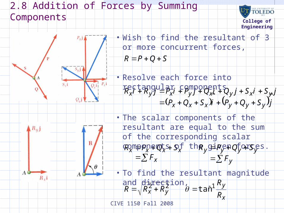
2.8 Addition of Forces by Summing Components
SQPR
• Wish to find the resultant of 3 or more concurrent forces,
jSQPiSQP
jSiSjQiQjPiPjRiR
yyyxxx
yxyxyxyx
• Resolve each force into rectangular components
x
xxxxF
SQPR
• The scalar components of the resultant are equal to the sum of the corresponding scalar components of the given forces.
y
yyyy
F
SQPR
x
yyx R
RRRR 122 tan
• To find the resultant magnitude and direction,

CIVE 1150 Fall 2008
College of Engineering
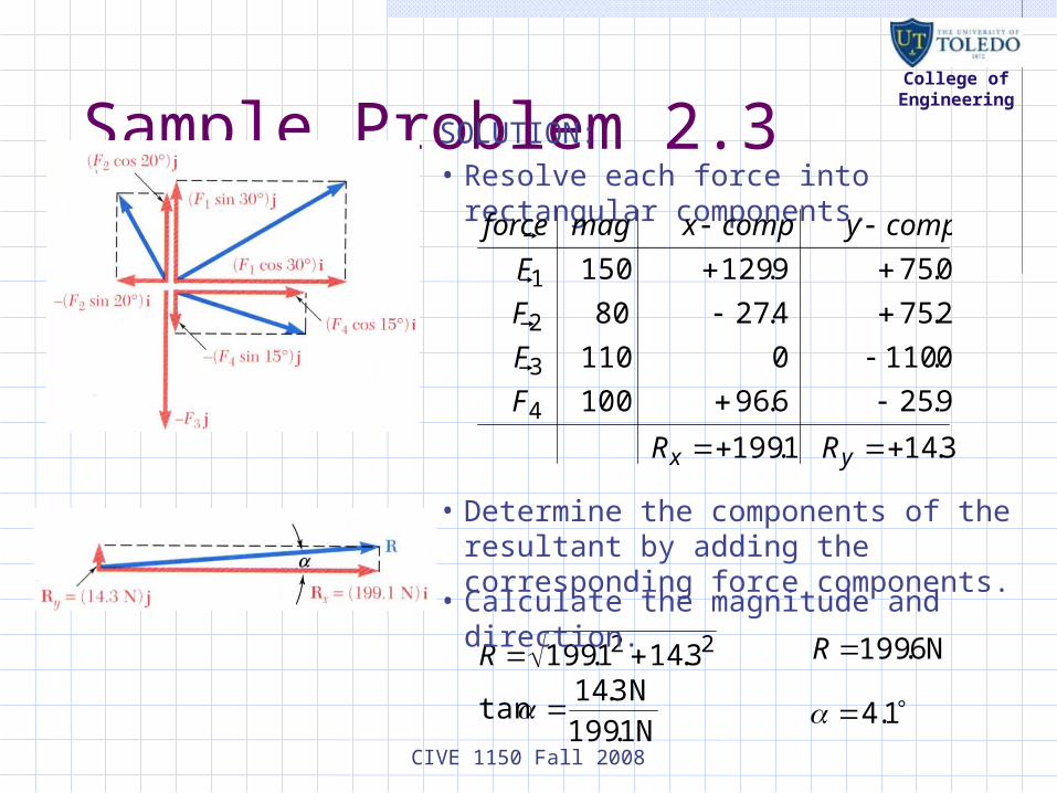
Sample Problem 2.3
Four forces act on bolt A as shown. Determine the resultant of the force on the bolt.
SOLUTION:
• Resolve each force into rectangular components.
• Calculate the magnitude and direction of the resultant.
• Determine the components of the resultant by adding the corresponding force components.
CIVE 1150 Fall 2008
College of Engineering
Sample Problem 2.3SOLUTION:
• Resolve each force into rectangular components.
9.256.96100
0.1100110
2.754.2780
0.759.129150
4
3
2
1
F
F
F
F
compycompxmagforce
22 3.141.199 R N6.199R
• Calculate the magnitude and direction.
N1.199
N3.14tan 1.4
• Determine the components of the resultant by adding the corresponding force components.
1.199xR 3.14yR

CIVE 1150 Fall 2008
College of Engineering
Equilibrium of a Particle• When the resultant of all forces acting on a particle is zero, the particle is in equilibrium.
• Particle acted upon by two forces:
- equal magnitude
- same line of action
- opposite sense
• Particle acted upon by three or more forces:
- graphical solution yields a closed polygon
- algebraic solution
00
0
yx FF
FR
• Newton’s First Law: If the resultant force on a particle is zero, the particle will remain at rest or will continue at constant speed in a straight line.

CIVE 1150 Fall 2008
College of Engineering
Free-Body Diagrams
Space Diagram: A sketch showing the physical conditions of the problem.
Free-Body Diagram: A sketch showing only the forces on the selected particle.

CIVE 1150 Fall 2008
College of Engineering
Sample Problem 2.4
In a ship-unloading operation, a 3500-lb automobile is supported by a cable. A rope is tied to the cable and pulled to center the automobile over its intended position. What is the tension in the rope?
SOLUTION:
• Construct a free-body diagram for the particle at the junction of the rope and cable.
• Apply the conditions for equilibrium by creating a closed polygon from the forces applied to the particle.
• Apply trigonometric relations to determine the unknown force magnitudes.

CIVE 1150 Fall 2008
College of Engineering
Sample Problem 2.4SOLUTION:
• Construct a free-body diagram for the particle at A.
• Apply the conditions for equilibrium.
• Solve for the unknown force magnitudes.
58sin
lb3500
2sin120sinACAB TT
lb3570ABT
lb144ACT

CIVE 1150 Fall 2008
College of Engineering
Sample Problem 2.6
It is desired to determine the drag force at a given speed on a prototype sailboat hull. A model is placed in a test channel and three cables are used to align its bow on the channel centerline. For a given speed, the tension is 40 lb in cable AB and 60 lb in cable AE.
Determine the drag force exerted on the hull and the tension in cable AC.
SOLUTION:
• Choosing the hull as the free body, draw a free-body diagram.
• Express the condition for equilibrium for the hull by writing that the sum of all forces must be zero.
• Resolve the vector equilibrium equation into two component equations. Solve for the two unknown cable tensions.

CIVE 1150 Fall 2008
College of Engineering
Sample Problem 2.6SOLUTION:
• Choosing the hull as the free body, draw a free-body diagram.
25.60
75.1ft 4
ft 7tan
56.20
375.0ft 4
ft 1.5tan
• Express the condition for equilibrium for the hull by writing that the sum of all forces must be zero.
0 DAEACAB FTTTR

CIVE 1150 Fall 2008
College of Engineering
Sample Problem 2.6• Resolve the vector equilibrium equation into two component equations. Solve for the two unknown cable tensions.
jT
iFT
R
iFF
iT
jTiT
jTiTT
ji
jiT
AC
DAC
DD
ACAC
ACACAC
AB
609363.084.19
3512.073.34
0
lb 06
9363.03512.0
56.20cos56.20sin
lb 84.19lb 73.34
26.60coslb 4026.60sinlb 40

CIVE 1150 Fall 2008
College of Engineering
Sample Problem 2.6
jT
iFT
R
AC
DAC
609363.084.19
3512.073.34
0
This equation is satisfied only if each component of the resultant is equal to zero
609363.084.1900
3512.073.3400
ACy
DACx
TF
FTF
lb 66.19
lb 9.42
D
AC
F
T

CIVE 1150 Fall 2008
College of Engineering
Rectangular Components in Space
• The vector is contained in the plane OBAC.
F
• Resolve into horizontal and vertical components.
yh FF sin
F
yy FF cos
• Resolve into rectangular components
hF
sinsin
sin
cossin
cos
y
hy
y
hx
F
FF
F
FF

CIVE 1150 Fall 2008
College of Engineering
Rectangular Components in Space
• With the angles between and the axes,F
kji
F
kjiF
kFjFiFF
FFFFFF
zyx
zyx
zyx
zzyyxx
coscoscos
coscoscos
coscoscos
• is a unit vector along the line of action ofand are the direction cosines for
F
F
zyx cos and,cos,cos

CIVE 1150 Fall 2008
College of Engineering
Rectangular Components in Space
Direction of the force is defined by the location of two points,
222111 ,, and ,, zyxNzyxM
d
FdF
d
FdF
d
FdF
kdjdidd
FF
zzdyydxxd
kdjdid
NMd
zz
yy
xx
zyx
zyx
zyx
1
and joining vector
121212

CIVE 1150 Fall 2008
College of Engineering
Sample Problem 2.7
The tension in the guy wire is 2500 N. Determine:
a) components Fx, Fy, Fz of the force acting on the bolt at A,
b) the angles x, y, zdefining the direction of the force
SOLUTION:
• Based on the relative locations of the points A and B, determine the unit vector pointing from A towards B.
• Apply the unit vector to determine the components of the force acting on A.
• Noting that the components of the unit vector are the direction cosines for the vector, calculate the corresponding angles.

CIVE 1150 Fall 2008
College of Engineering
SOLUTION:
• Determine the unit vector pointing from A towards B.
m 3.94
m30m80m40
m30m80m40
222
AB
kjiAB
• Determine the components of the force.
kji
kji
FF
N 795N 2120N1060
318.0848.0424.0N 2500
kji
kji
318.0848.0424.0
3.94
30
3.94
80
3.94
40
Sample Problem 2.7

CIVE 1150 Fall 2008
College of Engineering
Sample Problem 2.7
• Noting that the components of the unit vector are the direction cosines for the vector, calculate the corresponding angles.
kji
kji zyx
318.0848.0424.0
coscoscos
5.71
0.32
1.115
z
y
x