color atlas of endodontology
TRANSCRIPT

Endodontology

Color Atlas of Dental MedicineEditors: Klaus H. Rateitschak and Herbert E Wolf
EndodontologyRudolf Beer, Michael A. B aumann,and Syngcuk Kim
Translated byRichard Jacobi, D. D. S.Belton, TX, U.S.A.
1533 Illustrations
ThiemeStuttgart . New York . 2000
iv
Authors' Addresses
Editors' Addresses
Rudolf Beer, D. D. S., Ph. D.
Syngcuk Kim, D. D. S.,
Klaus H. Rateitschak, D.D.S., Ph.D.Dentist in Private Practice
M. Phil., Ph. D.
Dental Institute, Center for Dental MedicineEssen, Germany
Professor and Chairman
University of BasleSchool of Dental Medicine
Hebelstr. 3, 4056 Basle, SwitzerlandMichael A. Baumann,
Department of EndodonticsD. D. S., Ph. D.
University of Pennsylvania
Herbert F. Wolf, D.D.S.Department of
Philadelphia, PA, USA
Private PractitionerConservative Dentistry
Specialist of Periodontics SSPOral and Maxillofacial ClinicLowenstrasse 55, 8001 Zurich, SwitzerlandUniversity of CologneCologne, Germany
Library of Congress Cataloging-in-"" Important Note: Medicine is anPublication Data
In the Series
Color Atlas of Dental Medicine"
ever-changing science undergoingcontinual development. Research
Beer, R. (Rudolf) [Endodontologie.
and clinical experience are contin-English] Endodontology/Rudolf
K.H. & E.M. Rateitschak, H.F. Wolf,
ually expanding our knowledge, inBeer, Michael A. Baumann, and
T.M. Hassell
particular our knowledge of properSyngcuk Kim ; translated by Richard* Periodontolo
, 2nd edition
treatment and drug therapy. InsofarJacobi ; [illustrations by Albrecht
gy,
as this book mentions any dosage orRuech]. p. cm. - (Color atlas of
application, readers may rest assureddental medicine) Includes biblio-
A.H. Geering, M. Kundert, C. Kelsey
that the authors, editors, and pub-graphical references and index.
lishers have made every effort toISBN 3-13-116461-1 (hardcover :
• Complete Denture and Overdenture
ensure that such references are inGTV). - ISBN 0-86577-856-6
Prosthetics
accordance with the state of knowl-l. Endodontics Atlases.
edge at the time of production of2. Root canal therapy Atlases.
the book.1. Baumann, Michael A. 11. Kim,
G. Graber
Nevertheless this does not in-Syngcuk. 111. Title. IV. Series.
Removable Partial Dentures
volve, imply, or express any guarantee[DNLM: 1. Dental Pulp Diseases
or responsibility on the part of theAtlases. 2. Root Canal Therapy-
publishers in respect of any dosageinstrumentation Atlases. 3. Root
F.A. Pasler
instructions and forms of applicationCanal Therapy-methods Atlases.
stated in the book. Every user isWU 17 B415e 1999] RK 351.B4413
• Radiology
requested to examine carefully the1999 617.6'342-dc21 DNLM/DLC
manufacturers' leaflets accompany-for Library of Congress 99-28377
ing each drug and to check, if neces-CIP
T. Rakosi, I. Jonas, T.M. Graber
sary in consultation with a physician
Orthodontic Diagnosis
or specialist, whether the dosage
Illustrations by
schedules mentioned therein or the
Albrecht Ruech, Spay
contraindications stated by theH. Spiekermann
manufacturers differ from the state-
This book, including all parts
* Implantology
ments made in the present book.
thereof, is legally protected by
Such examination is particularly
copyright. Any use, exploitation, or
important with drugs that are either
commercialization outside the
H. F. Sailer, G. F. Pajarola
rarely used or have been newly
narrow limits set by copyright
* Oral Surgery for the General Dentist
released on the market. Every
legislation, without the publisher's
dosage schedule or every form of
consent, is illegal and liable to
application used is entirely at the
prosecution. This applies in particu-
R. Beer, M. A. Baumann, S. Kim
user's own risk and responsibility.
lar to photostat reproduction, copy-
The authors and publishers request
ing, mimeographing or duplication* Endodontology
every user to report to the publishers
of any kind, translating, preparation
any discrepancies or inaccuracies
of microfilms, and electronic data
noticed.
processing and storage
Some of the product names,and registered designs
This book is an authorized transla-
patents referred to in this book are in facttion of the German edition publishedand copyrighted 1997 by Georg
registered trademarks or proprietary
Thieme Verlag, Stuttgart, Germany.
names even though specific refer-
Title of the German edition:
ence to this fact is not always made
Endodontologie
in the text. Therefore, the appearanceof a name without designation as
© 1999 Georg Thieme Verlag, Rudi-
proprietary is not to be construed asgerstr. 14, 70469 Stuttgart, Germany
a representation by the publisherThieme New York, 333 Seventh
that it is in the public domain.Avenue, New York, N.Y 10001 USATypesetting by G. Miiller, HeilbronnPrinted in Germanyby K. Grammlich, Pliezhausen
ISBN 3-13-116461-1 (GTV)ISBN 0-86577-856-6 (TNY) 1 2 3

In recent years development was rapidly accelerated by
A few completely new techniques that are finding in-the introduction of rotating instruments made of nickel-
creasing usage have the potential to change our under-titanium alloys. With these instruments the root canal
standing of, and approach to, endodontic treatment. Forsystem can be prepared more efficiently, more predict-
example, diagnosis may be complemented by true sen-ably, more precisely, and with greater conservation of
sitivity testing through laser Doppler measurements.tooth structure than before. Continuing perfection of
Use of magnetic resonance techniques to produce im-the alloys and new improvements in cutting designs,
ages in the microscopic range would open the way to aalong with reliance on the fixed ISO standards of taper
three-dimensional reproduction of the endodontiumand cutting lengths, have contributed to vigorous
without the ionizing radiation of conventional radio-advancement in the field.
graphs, and perhaps will even reveal the histopatho--Gutta-percha, now as before, is considered the mate-
logic condition of the pulp tissue.rial of choice, and very good results can be achievedwith it using a wide range of thermoplastic filling
Unlike conventional textbooks, this atlas of endodon-methods.
tology covers a large number of endodontic cases in-The apicoectomy has been completely redefined
their entirety through the extensive use of illustrations,through the use of ultrasonic device and microinstru-
and demonstrates the practical interchangeability of thements under the surgical microscope, making it
methods presented. Through the familiar step-by-steppossible to operate more precisely and with less
manner of presentation that has proven so effective insacrifice of tooth structure.
previous Color Atlases of Dental Medicine, the prac--The operating microscope has already commanded
ticing dentist is provided with a convenient guide.an important place for itself in that, since I999, allpostgraduate courses in dental schools have madeits use mandatory. This adds to endodontic treatment
Essen, Cologne, and Philadelphia,a greater measure of sureness, precision, quality, and
in the summer of I999efficiency. The presence of four or more canals in
Rudolf Beer,maxillary molars will be recognized more frequent-
Michael A. Baumann,ly, many complications (e.g., fractures of instru-
and Syngcuk Kimments) will be avoided, removal of posts with newlyintroduced instruments will be facilitated, and moni-toring of treatment progress will be made simpler.
V
Preface

VI
Acknowledgments
Thanks are due first to those colleagues who by their
The essential component of an illustrated atlas forcontributions from their special areas have helped
conveying the scientific content is visualization. There-make this presentation of endodontology as complete
fore we must thank Albrecht Ruech who, with greatas possible:
expertise, breathed life into the drawings. He com-bines, in a unique way, the artistic gift with the ability
Dr. Adrian Lussi, Chief Physician of the Clinic for
to illustrate technical concepts. Throughout the projectConservative Dentistry, Dental Clinics of the Univer-
he maintained a spirit of enthusiasm and joy, and al-sity of Bern, Switzerland for his contributions related
ways kept an open ear to any discussion or suggestionsto certain aspects of caries diagnosis and especially for
dealing with the presentation.his new ideas on preparation and filling of the rootcanal system.
Mr. Stephan Gutbier and Mr. Thies Schoning (Depart-ment of Photography of the Dental Clinic, University
Dr. Christoph Benz, Professor and Chief Physician in
of Cologne) expertly produced a large portion of thethe Polyclinic for Conservative Dentistry and Peri- photographs of instruments and materials. We areodontology, Ludwig-Maximilians University, Munich,
grateful to them, as well as to Mrs. Susanne UrbanekGermany for his contribution on radiovisiography.
(MTA of the Department of Conservative Dentistryand Periodontology, Dental Clinic, University of
Dr. Theodore P. Croll, Doylestown Pediatric Dentistry,
Cologne) who prepared the SEM images of the instru-Doylestown, USA, for his cooperation with the topic
ments, and to Dr. Gerd Mayerhofer for the excellentof microabrasion and bleaching of teeth.
prosthetic treatment shown in some of the cases.
Dr. Matthias Frentzen, Professor and First ChiefPhysician at the Polyclinic for Conservative Dentistryand Periodontology, Rhenish Friedrich Wilhelms Uni-versity, Bonn, Germany. He prepared the chapter onlasers in endodontia.
Dr. James L. Gutmann, Professor and Director of theBaylor College of Dentistry, Dallas, USA, who con-tributed photographs for the chapters Root CanalObturation and Traumatic Tooth Injuries.
Dr. Markus D. W. Lipp, Clinic for Anesthesiology,Johannes Gutenberg University, Mainz, Germany,who presented information on local anesthesia.
Dr. Clifford J. Ruddle, Assistant Professor, Depart-ment of Graduate Endodontics, University of Cali-fornia, Los Angeles, and Santa Barbara, USA, whomade a contribution concerning vertical condensationof gutta-percha.

From the people at Thieme Verlag we always received
Such a large and comprehensive project as this Atlasideal support and attention to all details and questions
of Endodontology arises from the effective and open-that arose. In this regard our very special thanks are
minded interaction of all those involved. Therefore wedue to Dr. Bergman for his attention to the English
would like to thank not only those mentioned by name,language publications, and to Dr. Urbanowicz, Mr.
but everyone who contributed to its success by givingFleischmann, and Mr. Pohlmann. In addition, Mr.
a part of themselves, be it in the form of a photograph,Schwarz from the Reproanstalt Porupsky in Stuttgart
a useful piece of information, a technical consultation,had a large part in the transposition of all the illustra-
or simply a word of encouragement.tions and the excellent technical production of theentire atlas. We thank the two editors of the series
It requires more than an ideal medium for the successColor Atlases of Dental Medicine, Prof. Dr. Klaus
of an idea. Therefore the special thanks we give toRateitschak and Dr. Herbert F. Wolf, for their many
Dentsply Endodontics applies as well to all the othervaluable suggestions during the planning and forma-
firms that gave us their generous assistance.tion of the book into its present layout in keeping withthe unique spirit of the series.
Acknowledgments vii

v Prefacevi Aknowledgementviii Table of Contents
1
Pathology and Diagnosis
59
Instruments and Materials2
Diagnosis of Proximal Caries
60
The Three Basic Instruments...
4
Diagnosis of Fissure Caries
61
. . . and Their Modifications7
Smooth Surface Caries
62
I nstruments from Titanium Alloys
8 Reversible Pulpitis
64 Engine-Driven Instrumentation10 Acute Irreversible Pulpitis
66
Sonic and Ultrasonic Systems12 Presumptive Diagnosis
68 Microsurgical Endodontics14 Carious Pulp Exposure
69 Lasers in Endodontics16
Necrosis of the Pulp Tissue
70
-Vitality Test with the Laser Doppler Probe18
I ntentional Devitalization
70
-Laser Treatment of Cut Dentin and the Pulp
20
Filling Materials and Pulp Necrosis
71
-Vital Amputation22
Bacterial Infection in the Root Canal
71
-Sealing the Root Canal24
Treatment of Bacterial Infection
72
-Root Canal Preparation
26
Acute Apical Periodontitis
72
-Root Canal Disinfection28
Periapical Abscess
73
I rrigating, Drying, and Medicated Dressings30
Chronic Apical Periodontitis
74
Gutta-percha32
Chronic Apical Periodontitis and Radicular Cysts
76
Cold and Warm Condensation of Gutta-percha34
Radicular Cysts77
Rubber Dam35
Examination and Diagnosis
78
Rubber Dam Material36 Extraoral Examination
79 Rubber Dam Clamps37 Intraoral Examination
80 Additional Preparations38
Sensitivity Tests
81
Placing the Rubber Dam39
Clinical Examination and Selection of Therapy
81
-Rubber Dam Application I (Bow Technique)40
Radiographic Diagnosis and Interpretation
82 -Rubber Dam Application II (Wing Technique)42 Radiography in Endodontics
84 -Rubber Dam Application III (Rubber First)44
Digital Radiographic Technique
85
-Rubber Dam Application IV (Clamp First)44 -Intraoral Systems
86 Special Cases44 -Contrast Enhancement44
-Positive-Negative Representation
87
Local Anesthesia44 -False Color Representation
88 Anesthetic Solutions44 -Millimeter Grid
90
Selection45 -Resolution
90 Side Effects45 -Dynamic45 -Filters
91
Access Preparation45 -Projection Angle
92
I nterim Restorations
46
Uses of Digital Radiography
94
Opening the Pulp Chamber95
Uncovering the Canal Entrances47 Anatomy
96
Probing the Canal Entrances
48
Methods of Reproducing Root Canal Anatomy
98
Straight-Line Access to the Canals49
-Three-dimensional Computer Reconstruction
100
Obliterated Root Canals50
-Magnetic Resonance Imaging (MRI)
102
Locating Canals with the Surgical Operation Microscope51
Fundamentals
104 Chemical Aids51
-Classification of Canal Configurations52
-Maxillary Anterior Teeth
107
Root Canal Preparation
53
-Mandibular Anterior Teeth
108
Radiographic Length Determination54 -Maxillary Premolars
110
Difficulties in Length Determination55
-Mandibular Premolars
112
Loss of Working Length
56
-Maxillary Molars
114 Working Length with Apical Resorption
57
-Characteristics of Maxillary First Molars
116
Electronic Length Determination58
-Mandibular Molars
118
Cleaning and Shaping
VIII
Table of Contents

Table of Contents
ix
120
Balanced Force Technique
209
Retreatment of Endodontic Failures122
Step-Back Technique
210
Failures and Root Canal Anatomy124
Step-Down Technique (Crown-Down Technique)
212
I ndications for Retreatment126
Problem Solving during Instrumentation
214
Pain Following Root Canal Treatment126 -Step Formation
216 Removal of Post-Cores126
-Funnel Formation
218
Retreatment of Gutta-percha filled canals127 -Perforation
222
Removal of Broken Instrument Fragments127 -Overinstrumentation
228 Bypassing Fractured Instruments128
Surface of the Canal Wall Following Hand
230
Repair of Lateral PerforationsI nstrumentation
232
Repair of Coronal Perforations130
I nstrumentation under the Surgical Microscope132
I nstrumentation of Maxillary Molars
233
Microsurgical Endodontics134
Engine-Driven Canal Instrumentation
234
Principles of Endodontic Microsurgery136
I nstrumentation with Profile
235
Illumination and Magnification138
I nstrumentation with Tri Auto ZX
236
I ndications for Surgical Procedures140
I nstrumentation with the Quantec Series 2000
237
Presurgical Examination142
I nstrumentation with Lightspeed
238
Flap Design144
Canal Surface After Engine-Driven Instrumentation
238
-Mucoperiosteal Flap239 -Full Thickness Flaps
145 Disinfection
240 Apical Resection146
Microbial Infection of Root Canals
241
Resection Angle148
Root Canal Irrigation
242
Hemostasis150
I rrigation of the Periapical Lesion
243
Microscopic Inspection of the Resected Surface152
Ultrasonic Root Canal Irrigation
244
I sthmus154
Removal of the Smear Layer
246
Clinical Treatment of the Isthmus156 Antibacterial Interim Dressings
248
Retrograde Preparation with Ultrasonic Instruments158
Application of Calcium Hydroxide (Ca[OHj2)
250
Drying the Retrograde Preparation160
I nterim Dressing for Chronic Apical Periodontitis
251
Retrograde Obturation162
I nterim Dressing for Acute Apical Periodontitis
252
Super EBA (ethoxybenzoic acid) Cement164
Clinical Results
254
Effect of Sutures on Soft-Tissue Healing
165
Root Canal Obturation
255
Traumatic Tooth Injuries166 Biological Properties
256 Classification167 Physical Properties
258 Crown Fractures168
Prerequisites for Filling the Root Canal
260
Crown-Root Fractures170
Lateral Condensation of Gutta-percha
262
Vertical Root Fractures172
Adaptation of Gutta-percha
264
Cracked Teeth176 Corrections During Condensation178
Gutta-percha Master Point Too Long
267
Postendodontic Restoration180
Gutta-percha Master Point Too Short
268
Provisonal Coronal Seal182
Thermomechanical Condensation
270
Fracture Risk and Partial Veneer Crowns183 Thermafil
272 Coronal Restoration184 Thermoplastic Injection Technique
274
Endodontic Posts186 Three-Dimensional Gutta-percha Fillings
278 Cast Post-Cores188 Vertical Condensation: Part I
280
Coronal Restorations and Treatment Results190 Vertical Condensation: Part II
282
Restoration of Hemisected Teeth192 Clinical Results194
Fully Automatic Method of Root Canal Preparation
283
Bleaching of Teeth196
Fully Automatic Method of Root Canal Obturation
284
Causes of Tooth Discoloration198 Heated Gutta-percha
286 Thermocatalytic Bleaching287 Walking Bleach Technique
199
Endodontics in the Deciduous and Mixed Dentitions
288
Microabrasion Method200
Pulpotomy in the Deciduous Dentition
290
Nightguard Vital Bleaching202
Pulpectomy in the Deciduous Dentition203
Direct Pulp Cap
293
References204
Pulpotomy in the Mixed Dentition206
Teeth with Developmental Defects
305
Illustration credits206 -Dens Invaginatus207 -Lingual Groove in the Root
306
Index208 Apexification

My thanks go to my wife Mariannewho substantially furthered the success of this workthrough her special contributions.
Rudolf Beer
My wife Uta Annette andour daughter Helena Uta Reginadeserve my special thanks for their loving support.
Michael A. Baumann
1
Pathology and Diagnosis
Intensive microbiologic, immunologic, and morphologic research investigations, especiallyduring the past decade, have shown that colonization of tooth surfaces by pathogenic bacteria isaccompanied by humoral and cellular defense mechanisms of the organism not only during themore advanced stage of infection, but also throughout the initial stages. Penetration of thesecomplex defenses, which is usually of limited duration, disturbs the equilibrium of the system andresults in disease. Within the dental pulp, this biologic equilibrium has to do with the balancedcalcium and phosphate ion exchange during the continuous demineralization and remineralizationof the enamel and exposed dentin. As long as a disease process is reversible, as is incipient caries,the capacity for progression and regression is present. Carious breakdown means that enamel isbeing demineralized by acidogenic plaque more rapidly than it can be remineralized. Now, in itsearly stages, the caries has become a chronic destructive process, in which irreversible structuralchanges will preclude any further remission.
If one looks at the dynamics of demineralization and remineralization, and the etiology ofcaries against the epidemiologic background, and compares these with the results of therapy, apattern of active disease spurts alternating with resting phases emerges. During these periods ofremission, the chronic destructive process is not reversed, but is only brought to a standstill. Thisconcept of progression and stagnation (Socransky et al. 1984) is strongly influenced by thedefensive capability of the organism.
Progression is defined by invasion of caries into dentin with inflammation and loss of connec-tive tissue. Stagnation means the defenses are increased, there are defensive inflammatory cellsin the tissues, and connective tissue is being replaced by secondary dentin or granulation tissue.Histologically, this ever-changing dynamic process in carious teeth is recorded over the yearsthrough deposition and destruction of dentin.
For the practitioner, the obvious questions that arise are how to classify the histopathologiccondition of the pulp and the apical periodontal tissues, and how to initiate treatment that isappropriate, considering the background of stagnation or progression. Based upon clinicalfindings, differentiations are made between a clinically sound pulp, reversible pulpitis,irreversible pulpitis, a necrotic pulp, and apical periodontitis. These distinctions are based solelyupon clinical observations; generally, a correlation between certain symptoms and a specificpathologic entity cannot be expected. Making the distinction between reversible and irreversibleinflammations of the pulpal tissues can be a diagnostic problem, because they can present similarclinical symptoms. Histologically, the diagnosis of acute inflammation is based upon thepredominance of neutrophilic granulocytes. However, this diagnostic picture does not alwayscoincide with the appearance of pain symptoms because neutrophilic granulocytes can also befound in cases where there is no pain (Langeland 1981, Lin and Langeland 1981 b, Lin et al.1984).

1
Incipient enamel cariesA Extracted tooth with incipient
proximal caries just below thecontact point.
B The histologic preparation de-monstrates an intact surfacelayer (10-30 pm thick). It issharply demarcated from thebody of the lesion. This regionshows a markedly decreasedmineral content. In the adjacentdark zone there are relativelyl arge as well as small micro-pores. The first carious structuralchanges appear in the transpar-ent zone.
C Clinical appearance of a brown-spot lesion with cavitation.
D A completely intact surfacel ayer can no longer be distin-guished. The body of the carieshas already penetrated throughthe enamel as early dentinalcaries.
2
Pathology and Diagnosis
Diagnosis of Proximal Caries
Caries begins with microscopic demineralization of the
man and van der Weele 1990, Noar and Smith 1990).affected enamel or cementum surface. As it progresses,
Most studies found that where there is a dentinal le-the enamel first becomes chalky, then its surface is bro-
sion, there is a surface that has been broken through,ken through. In this stage, the caries is easy to detect,
which precludes any chance for remineralizationbut has frequently progressed so far that extensive re-
(Marthaler and Germann 1970; Bille and Thylstrupstorative and endodontic treatment in necessary. More
1982; Mejare and Malmgren 1986). Even though thedifficult to diagnose, on the other hand, are lesions that
actual extent of caries is underestimated with the ra-are in their early stages and dentinal lesions with
diograph, it may be concluded that the specificity, thatmacroscopically intact surfaces. Finally, a decision
is, the ability to recognize sound teeth as sound, is ap-must be made as to whether preventive measures will
proximately 95% (Mileman and van der Weele 1990).suffice or whether invasive restorative measures must
New, more sensitive X-ray films seem to be the equalbe taken.
of earlier films as far as caries diagnosis is concerned.Epidemiologic studies have shown that-coincident
Because they produce the same degree of contrast withwith a general decrease in caries prevalence in indu-
significantly less radiation, their use is now highly re-strialized countries-the occlusal surfaces of the per-
commended. Preventive measures can impede furthermanent molars of children and young adults are the
penetration and even promote remineralization, provid-surfaces most frequently attacked by caries. In contrast
ed that the enamel surface has not yet been disrupted.to fissure caries, proximal and smooth surface caries is
The progression of caries can be monitored with peri-much less frequent. Radiographically evident incipient
odic radiographs. Their interval depends, among otherlesions in enamel of the proximal surfaces have like-
things, upon the individual's susceptibility to caries.wise shown a decline. In adults, the probability that
Patients at high risk of caries should be radiographedthese lesions would penetrate further has increased,
every year while those at very low risk need only beand this has caused the proportion of proximal caries to
radiographed every 2-4 years. The time in which itrise again.
takes caries to penetrate the enamel of a mature per-In the diagnosis of proximal caries, clinical exami-
manent molar in a patient with good oral hygiene cannation, bitewing radiographs, and fiberoptic transillu-
exceed 5 years. This offers the opportunity to post-mination (FOTI) can be called upon. During examina-
pone invasive restorative treatment and to observetion with an explorer, many carious lesions with cavity
whether the caries progresses or regresses. The rate atformation go undiagnosed. Bitewing radiographs are which penetration progresses can be estimated bystill the method of choice for the diagnosis of approxi-
comparing radiographs produced at different times bymal caries, and account for the detection of approxi-
a standardized technique. Recently erupted teeth, onmately three-fourths of dentinal carious lesions (Mile-
the other hand, demonstrate a markedly reduced pene-

Diagnosis of Proximal Caries
3
tration time (Marthaler and Wiesner 1973, Shwarz et
diograph should be inspected carefully under magnifi-al. 1984).
cation and away from the influence of any light comingIn order to minimize overlapping of the images of
from the sides.approximating tooth surfaces, a film holder is recom-
FOTI can be used in addition to bitewing radio-mended. A deviation of the horizontal angle of the X-
graphs if there is no interference from adjacent inter-ray tube by only a few degrees will result in a substan-
proximal fillings that are other than tooth colored.tial decrease in correct diagnoses. The image of enamel
More than 70% of dentinal lesions in anterior teeth cancaries projected into the dentinal area can lead to a
be detected by means of FOTI. Dentinal lesions in pos-false positive diagnosis. Radiolucency in dentin should
terior teeth, however, can be differentiated only withbe treated as invasive only if there is also an un-
great difficulty (Pieper and Schurade 1987, Choski etmistakable radiolucency in the enamel region. The ra-
al. 1994).
2 Extent of cariesThe radiograph does not reveal thefull extent of the caries.
View of the proximal surface of adeciduous tooth with i ncipientcaries.
Left: Radiograph of the deciduoustooth. The radiolucency barely ex-tends into the dentin.
3 Extent of cariesA histologic section through thecenter of the lesion reveals a defi-nite invasion into the dentin.
Left: A histologic section throughthe border of the lesion shows ex-tension into the dentin (UV light).
4 Clinical appearance andbitewing radiographThe bitewing radiograph revealsextensive destruction of toothstructure in both the mesial anddistal regions of the upper left firstmolar.
Left: Under clinical inspection, analteration of color can be clearlyseen only on the mesial of thesame molar.

4
Pathology and Diagnosis
Diagnosis of Fissure Caries
In addition to clinical examination, bitewing radio-
The electrical resistance between a tooth and a handgraphs, and fiberoptic transillumination, another diag-
electrode depends upon the condition of the tooth. Thenostic method that can be used is the measurement of a
greater the amount of tooth structure that has been de-tooth's resistance to an applied electrical current.
stroyed and replaced by a more conductive medium,Studies have clearly demonstrated that the additio-
the less the resistance (Lussi et al. 1995 a). This pro-nal use of an explorer does not improve the diagnostic
perty is utilized in caries diagnosis by means of the el-results (Lussi 1991, 1993). It appears that an explorer
ectric caries meter. It is expected that in the future, thesticks in a fissure more because of the anatomy than
measurement of electrical resistance will be used morebecause of caries. The explorer has additional disad-
and more. This method is especially valuable for de-vantages in that microorganisms are transferred from
tecting caries under a seemingly intact surface (Flaitzone place to another, and superficially decalcified areas
et al. 1986). Because the electric caries meter measurescan be damaged. In some situations, this can lead to ac-
the extent of caries only at individual points, we re-celerated caries progression. It is recommended, there-
commend that this method be used as additional verifi-fore, that the explorer-if it is to be used at all-be
cation when the clinical diagnosis is uncertain. Fur-used only as a tactile instrument with light pressure. It
thermore, it can be used for longitudinal observation ofcan also be used to remove plaque from the depths of
a suspicious area and provides information on the suc-the fissures.
cess of intensive preventive treatment.Bitewing radiographs, on the other hand, permit
FOTI of fissure caries is difficult to interpret be-more accurate diagnosis and should therefore be appre-
cause of interference from stained fissures and fillingsciated for their value in diagnosing fissure caries also.
that are not tooth colored. Apart from this, occlusalIt should be mentioned in this regard that only the
dentinal caries frequently affects only a small part ofocclusal caries that extends into the dentin can be iden-
the total mass of tooth that is transilluminated and there-tified on radiographs.
fore may not stand out clearly.
5 Fissure anatomyLeft: The fissure on this molar ex-tends almost to the dentinoenameljunction and exhibits varying areasof red-stained decalcification.
Right: Scanning electron micro-graph of the occlusal surface ofthis molar.
6 ECM caries meterLeft: Use of the ECM caries meteron a patient: air reaches the tooththrough the opening in themeasuring probe and dries it sothat the resistance between thetooth and hand electrode can bemeasured.
Right: This overview shows, fromleft to right, the measuring probe,air-flow regulator gauge, and thehand electrode.
Collection A. Lussi

7 Extent of fissure cariesA histologic section through thecenter of the fissure of a molar un-mistakably shows dentin involve-ment (UV light).
Left: Occlusal surface of the molarthat was judged to be intact by 20out of 26 dentists.
8 Extent of fissure cariesFarther toward the periphery thedentinal caries is still clearlyvisible (UV light).
Left: Radiograph with dentinalradiolucency.
9 Extent of fissure cariesEven a section through an areawith no overlying fissure shows de-finite decalcification (UV light).
Histology by H. Stich
10 Summary
Diagnosis of Fissure Caries
5

6
Pathology and Diagnosis
11
Breakdown of the enamelsurfaceDentinal lesions that are clearlyvisible on the radiograph frequent-l y show a breakthrough to the sur-face, especially in caries-activepatients. In these cases, reminera-lization is not possible. This radio-graph shows a distinct radiolucen-cy on the mesial of the lower rightfirst molar.
Right: Clinically, a breakdown ofthe mesial surface of the molar canbe seen.
12 Fiberoptic transillumination(FOTI)This is especially useful for exam-i ning anterior teeth and proximalsurfaces that are free of interferingopaque restorations.
13 Fiberoptic transillumination(FOTI)Transillumination clearly disclosescaries on the distal of the canine.
Collection A. Lussi
14 Summary

15 Incipient lesion(chalky spot)With good oral hygiene, smoothsurface caries progresses slowlyor may even become invisible overti me. The area of well-calcifiedenamel gingival to the lesion indi-cates that there has been a lengthycaries-inactive phase.
16 Incipient lesion(10 years later)The chalky area has increasedonly slightly. The minimal break-down of the surface in the distalportion of the incipient lesion doesnot require restoration at this time.
Collection A. Lussi
17 Summary
Smooth Surface Caries
7
Smooth Surface Caries
Today, facial and lingual smooth surface caries is seen
the chalky spot and the gingiva is evidence of aonly infrequently in Switzerland, Germany, other Eu-
prolonged inactive phase (Fig. 15). Smooth surfaceropean countries, and in the USA. If oral hygiene is
lesions with intact surfaces are "treated" with optimiz-good these lesions progress slowly, remain static, or ed prophylaxis, including fluoride applications. Aeven remineralize very well, as has been shown in the
restoration is necessary only when the surface hasclassic study by Baker-Dirks (1966). After a 7-year ob-
broken down.servation period with good oral hygiene, more thanhalf of the incipient lesions ("chalky spots") hadchanged so much that they were reclassified as sound.Very few of the initial lesions had developed intocavities 8 years later. A band of sound enamel between

8
Pathology and Diagnosis
Reversible Pulpitis
The first inflammatory reactions within the pulp occur
found large numbers of bacteria (Yamada et al. 1983).when caries from an enamel lesion invades the dentin
If a chronic superficial carious lesion is present, a(Langeland et al. 1973). Histologically, neutrophilic
small amount of tertiary dentin will have formed andgranulocytes, lymphocytes, and macrophages are seen
there will be a reduction of the odontoblastic borderin the odontoblastic layer. The odontoblastic processes
(Kuwabara and Massler 1966, Baume et al. 1970).end in a layer of sclerosed dentin, where at first most-
Arrested caries media is characterized by the forma-ly peritubular dentin is formed, followed by minera-
tion of tertiary dentin, reduction of the odontoblasticlization of the odontoblastic processes (Frank and Voe-
layer, and cellular infiltration. Where active caries isgel 1980). The processes in the uppermost layer of
present, there is not only damage to the odontoblasts,carious dentin exhibit fringed ends with membranous
but also massive infiltration of inflammatory cellsfragments in the lumens of the tubules. Here are also
(Massler and Pawlak 1977).
18 Dentinal caries and pulpitisA Slowly progressing dentinal ca-
ries with clear destruction of thedentinoenamel covering has ledto the formation of irregularstimulated dentin as protectionagainst further infiltration oftoxins.
B Within the coronal pulp tissue,several hard-tissue deposits orfibrodenticles can be seen.
C An enlarged section of theregion of stimulated dentinshows an odontoblastic layerthat is badly destroyed in places.The stimulated dentin (tertiarydentin) has relatively few tubulesand is bounded by a few, relati-vely newly differentiated, odonto-blasts. The adjacent pulp tissuei s nearly normal in structure.
D Fibrodenticles (as intrapulpaldentin) arise as the result ofpathologic stimuli. Atubularosteoid denticles are formed byremote pulpoblasts (Baume1 980).
19 Reversible pulpitisA There is no evidence of hard-
tissue formation in the pulphorn-endotoxins can penetrateunimpeded into the pulpaltissue.
B Close to the deepest part of thecaries the odontoblastic layerand capillary plexus are dis-rupted, and frequently onlyfragments can be found.
C Lysosomal enzymes causenecrosis of endothelial cells, in-creased vascular permeability,and extravascular edema.
D/E As bacteria move into the den-tinal tubules form the coronalside, neutrophilic granulocytesmigrate into the entrances ofthe corresponding tubules onthe pulpal side, decompose,and release tissue-destroyingenzymes.

21 Pain mechanismAfferent innervation of the dentalpulp is through thin myelinated Adelta fibers and nonmyelinated Cfibers. Both are responsible forconduction of pain signals. Theformer are said to mediate a sharp,well-localized pain sensation whilethe latter are associated with dull,diffuse pain.
Three theories of the origin ofdentinal pain will be discussed:first, the hydrodynamic theory withmovement of fluid within the dentin-al tubules; second, direct nervestimulation; and third, odontoblastsfunctioning as receptors and syn-aptic transmitters. Sensory nerveendings in an inflamed region maybe stimulated by an increase in in-trapulpal pressure, a change in pH,and through the release of pros-taglandin and other mediators ofi nflammation as well as decompo-sition products. This process isenhanced by the release of neuro-peptides from nerve fibers so thatnormally tolerable stimuli are per-ceived as painful (Raab 1993).
20 Nerve fibers in the pulpI rritation of free nerve endings canbe at the root of dentinal pain.Electron microscopic studies haveshown nonmyelinated nerve fiberscontiguous with odontoblastic pro-cesses at the dentinoenamel junc-tion (Frank and Nalbandian 1989).
Left: nonmyelinated nerve fibers.
Right: myelinated nerve fibers.
Transmission electron microscope(TEM): F. F. Eifinger
Reversible Pulpitis
9
Under the deepest part of the caries, dissolution of
regions within the coronal pulp, although damage tothe odontoblastic border and loosening of the capillary
the remaining pulp tissue is a real danger. Pathologicplexus occurs, and frequently only isolated fragments
mineralization along the canal wall and the first appea-of blood vessels can be seen (Gangler and Seinige
rance of denticles are further changes that occur (Lan-1979). The enzymes released by damaged granulocytes
geland 1981, Beer and Gangler 1986).and macrophages cause necrosis of the endothelial
If a restoration is performed at this stage, the endo-cells, and this results in increased vascular permeabili-
dontic inflammation is reversible, although changesty and extracellular edema (Torneck 1981). Nerve fi-
within the pulp tissue may remain as "scar tissue"bers appear to remain relatively undamaged in this
(Beer 1992b).stage of the carious attack (Torneck 1974). The inflam-mation gradually spreads, but is still confined to small

22 Caries and pulpitisA Advanced dentinal caries be-
neath the fissure has reachedthe pulp tissue, causing acircumscribed area of inflam-mation.
B The enlarged section shows acircumscribed area of odonto-blastic destruction with no for-mation of secondary dentin as aprotective reaction. There isalso massive infiltration of in-flammatory cells in the adjacentpulp tissue.
C The penetration of bacteria intothe dentinal tubules triggerschemotactic attraction of neu-trophilic granulocytes. Thesegranulocytes can be seen inboth the adjacent pulp tissueand the affected dentinal tubu-l es. "Empty spaces" within thesubodontoblastic l ayer areareas of micronecrosis with ac-cumulations of pus, and containadditional polymorphonucleargranulocytes.
23 Accumulation of inflamma-tory cellsA The region opposite the carious
destruction of the odontoblasticlayer is dominated by neutrophi-li c granulocytes. These can beseen both around and within theblood vessels; the expression ofa persistent chemotactic attrac-tion. The large "empty spaces"i ndicate incipient tissue necrosis.
B The surrounding tissue containsboth acute polymorphonucleargranulocytes and chronic mo-nonuclear granulocytes.
C In the adjacent area are plasmacells and lymphocytes that canproduce, among other things,lymphokines. A distinction ismade between factors that ac-tivate macrophages and denti-noclasts and those that impedecell migration. As lymphotoxinsthey can also have a direct de-structive effect upon tissues.
10
Pathology and Diagnosis
Acute Irreversible Pulpitis
As bacteria spread into the dentinal tubules, neutrophi-
The irritants that intensify the inflammatory reactionlic granulocytes migrate toward the entrances of the tu-
are bacteria, their metabolites and decomposition pro-bules bordering on the pulp, disintegrate, and in doing
ducts, and lastly, decomposition products of the affect-so release lysosomal enzymes that cause destruction of
ed dentin. At this time a vicious cycle is establishedpulp tissue. During the associated phagocytosis of the
and irreversible pulpitis becomes manifest (Langelanddestroyed tissue by polymorphonuclear and mo- 1981).nonuclear phagocytes, these leukocytes ingest cell
The pulp closely surrounding the necrotic region be-fragments, and release lysosomal enzymes that subse-
comes permeated by neutrophilic granulocytes thatquently cause tissue destruction and a chemotactic at-
phagocytize bacteria. This causes liquefaction of entiretraction of more inflammatory cells (Wright 1982).
regions of pulp tissue with the process spreading in anapical direction (Lin et al. 1984).

Acute Irreversible Pulpitis
11
The histologic picture of acute inflammation with a
reaction appears to be the penetration of toxins throughpredominance of acute inflammatory cells does not
intact radicular pulp tissue. Endotoxin that is releasedmean, however, that all the clinical symptoms of acute
from the outer membrane of Gram-negative bacteria isinflammation will be present. Langeland (1981) could
able to initiate a complement reaction. The activationuncover no history of pain symptoms in 81 of 224 teeth
of complement causes the release of biologically activewith deep caries, partial pulp necrosis, and severe in-
peptide, whereupon the vascular permeability increasesflammation. In addition, there was no correlation be-
and neutrophilic granulocytes and macrophages are at-tween the depth of caries and the occurrence of pain.
tracted. Enzymes that are released during phagocytosisFrequently in cases of irreversible pulpitis with necro-
then produce destruction of bone tissue (Pitts et al.sis within the pulp, widening of the apical periodontal
1982).space also occurred. The cause of this early periapical
24 Inflammation-free rootcanal pulp tissueA The carious invasion and the
region of inflammation in thecoronal pulp can be seen in thiswide-angle view, whereas thepulp of the root canal is vitaland free of inflammation.
B The root canal pulp contains afew diffuse calcifications andhard-tissue deposits on thedentin of the canal wall.
C The odontoblastic layer is intactwithout inflammatory cell infil-tration. In addition, the sub-odontoblastic space is normali n structure. The course of thedentinal tubules shows no irre-gularities that would indicatetoxic damage.
D Under higher magnification asingle calcification can be seeni n the root canal. The adjacentpulp tissue is vital and free ofi nflammation.
25 Periapical inflammationA The pulp of the root canal is
free of inflammation, but therei s granulation tissue in theperiapical region. A periapicalradiolucency is also visible onthe radiograph.
B The pulp of the root canal istotally free of inflammation. Thei solated hollow spaces are arti-facts caused by the preparationtechnique. The formation ofvacuoles can be the result ofdelayed fixation of the tissue,too short a fixation time, andfixation under pressure whichcan cause postmortem settlingof tissue. These are not relatedto degenerative changes (Lan-geland 1957, Beer 1 983).Mononuclear cells are visibleperiapically.
C In this enlarged view of the peri-apical region the adherent gra-nulation tissue can be identified.

26 Inadequate restorationsThis 31-year-old patient had com-posite fillings placed in the upperanterior teeth 3 months earlier,after which recurring pain was ex-perienced, initiated by eating anddrinking and ceasing only briefly.
The fillings are easily removedwith an explorer. Residual caries isfound under the defective fillingsi n the maxillary right incisors andcanine.
Right: Radiogaph of the affectedanterior teeth following caries re-moval.
27 Caries excavationAfter removal of the restorations,all secondary caries is removedunder anesthesia, care beingtaken not to expose pulp. It is im-portant during caries excavation touse radiographs to gauge theproximity to the pulp.
The photograph shows a fewsmall areas of residual caries.These must be completely removed.
Finally, a thick mix of zincoxide-eugenol (with no other addi-tives) is applied and left in placefor 24 hours.
28 Acute reactionThe next morning the patient pre-sents with pronounced swellingover the canine fossa. The pati-ent's general condition has alsodeteriorated. The diagnosis is re-vised to irreversible pulpitis in thei nvolved teeth. Treatment of thecarious lesions has precipitatedacute inflammation.
Right: The abscess is opened bymeans of an incision at the transi-tion to moveable mucosa with re-flection of the periosteum.
12
Pathology and Diagnosis
Presumptive Diagnosis
The objective of endodontic diagnosis is to determine
Tenderness to percussion of the tooth in question is
which teeth are to be treated and to define the patholog-
an early and sure sign of endodontic inflammation, but
is condition of the pulp and the periradicular tissue.
does not mean that there is complete necrosis. It is not
Aside from the clinical findings, the subjective pheno-
possible to differentiate precisely between a clinically
menon of pain presents an essential criterion for esti-
healthy pulp, reversible pulpitis, and irreversible pulpi-
mating the condition of the pulp, although generally a
tis by means of a sensitivity test. A positive reaction
direct correlation between the histopathologic conditi-
can occur even in the presence of a small periapical
on and the patient's clinical symptoms cannot be ex-
radiolucency (Lin et al. 1984). The radiographic
pected. Tooth pain is an expression of an irreversible
examination can support the differential diagnosis only
tissue change in only about one-third of patients.
in conjunction with the clinical examination.

Presumptive Diagnosis
13
Where there is reversible pulpitis the caries has not
The cavity is filled with a stiff paste of zinc oxide-yet entered the pulp. There may be exposed dentin or a
eugenol with no additives. After the tooth has beendefective restoration. Pain is initiated by cold, sweet,
asymptomatic for no less than 48 hours, it may beand sour stimuli with hypersensitivity of short dura-
restored by placing a biologically neutral base andtion. The radiograph usually shows a deep carious le-
covering this with a permanent filling material. If painsion or an old filling with nothing abnormal about the
persists or increases, we are dealing with irreversibleperiapical region. Treatment for the reported pain is
pulpitis. In this case the root canal(s) must be instruinitiated by removing old fillings and thoroughly exca-
mented and later filled.vating all caries. Under no circumstances should anycaries be left remaining. While waiting for the clinicalsymptoms to subside, a palliative filling is indicated.
29 Access preparations androot canal treatmentThree days following opening ofthe abscess, all three root canalsare instrumented under a rubberdam. Because the pulps are al-ready partially necrotic, the canalsshould not be obturated until atl east 3 weeks after canal prepara-tion. At this stage, therefore, thecanals were loosely filled with acalcium hydroxide paste by meansof a spiral filler.
Left: Preparations are completedi n all three root canals because thesource of infection cannot be moreprecisely determined.
30 Root canal preparationAt the next appointment, 3 weeksafter the initial preparation, thepatient is free of symptoms so thei nterim dressings are removed.The three root canals are cleanedto the depths of the master files,then dried with paper points.
At the same appointment thecervical cavities are restoredunder the rubber dam. Glass iono-mer bases are placed, the marginsbeveled, the cavities etched, treat-ed with a bonding agent, and filledwith a microfilled hybrid composi-te.
31
Root canal fillingThe root canals are filled aftermeasuring and insertion of thegutta-percha master points follow-i ng the lateral condensation tech-nique. A calcium hydroxide basedsealer is used. The primary gutta-percha points are of standard ISOsizes and are the same colors asthe corresponding master files.
Left: The control radiograph showshomogenous filling of the rootcanals. The patient has remainedsymptom-free.

32 Pulpitis aperta granulo-matosa, "pulp polyp"A Extensive carious exposure of
the pulp is observed. Bacteriareaching the pulp have causedulceration and a massivegathering of inflammatory cells.Granulation tissue has begun tosprout out of the ulcerated pulptissue and extrude through thecoronal opening.
B The coronal pulp tissue isepithelialized and composedpredominantly of firm connec-tive tissue. It is rich in collagenfibers with relatively few bloodvessels, and contains numerousnerve fibers reaching into theepithelium. Areas of chronic in-flammatory infiltration are alsopresent.
C The surface is colonized byepithelial cells from the gingiva.The stratified squamous epithe-li um corresponds to keratinizedgingival epithelium.
33
Necrosis of the pulp tissuei n the root canalA The bacterial infiltration of the
coronal pulp tissue leads tonecrosis with destruction of tis-sue. An accumulation of poly-morphonuclear leukocytes isfound within the ulcerated tis-sue bounded at the transition tothe root canal entrance by awall of mononuclear leukocytes.Granulation tissue can also beseen in the periapical region.
B The enlarged section of thecoronal third of the root canalexhibits infiltration with inflam-matory cells, tissue destruction,and disruption of the odonto-blastic layer.
C/D Monocytes dominate the in-flammatory infiltration. Afterlymphocytes, plasma cells arethe most numerous, indicating al ocal immune response.
14
Pathology and Diagnosis
Carious Pulp Exposure
With carious pulp exposure, a large number of dying
dentin in a deep cavity has been broken through, in-and necrotic cells can be seen within the pulp tissue
flammation will occur in the pulp after 7 days. Theunder the electron microscope. Lymphocytes, plasma
odontoblastic layer becomes disorganized and infiltrat-cells, and macrophages can be identified bordering on
ed with neutrophilic granulocytes. Bacteria, necrosis,the focus of necrosis. Polymorphonuclear leukocytes
and cell fragments are present, and there is very littledominate superficially, some intact and some frag-
production of tertiary dentin (Furseth et al. 1980).mented with organelles spread through the extracellu-
Injection of a bacterial extract into exposed pulp willlar space (Torneck 1981). Microorganisms can be
cause local abscess formation with resorption of bone,found inside neutrophilic granulocytes and macropha-
cementum, and dentin (Stabholz and Sela 1983).ges. The endothelial cells of the blood vessels are dam-aged and leukocytes have been released. If carious

Carious Pulp Exposure
15
Granulation tissue may begin to grow out from ex-
This chronic open pulpitis is, in contrast to theposed and ulcerated pulp and swell out of a wide coro-
closed forms of pulpitis, easy to diagnose clinically. Ifnal opening as an enlarging tissue mass. This pink glo-
the progression of caries has created a wide opening inbular tissue can become colonized by epithelial cells
the roof of the pulp chamber, secretions can flow outfrom the junctional epithelium and then become epithe-
and the clinical situation is painless. The treatmentlialized. A distinction is made between "young pulp
consists of first removing the pulp tissue down to thepolyps" that arise from hyperplastic granulation tissue,
entrance to the root canals, after which the canals areand "old pulp polyps" which are tough connective tis-
instrumented. Because tissue necrosis is present, thesue with epithelialized surfaces (Schroeder 1991).
canals are not filled until an intermediate dressing hasbeen in place for 1 month.
34 Open pulpitisHyperplastic pulp tissue has bro-ken through the buccal surface ofan upper molar. As a result of therelease of lymphokinin, dentino-clasts were activated in the surfaceof the tissue and these producedresorption of the buccal wall.
Four years previously a pulpo-tomy was performed due to pulpexposure during caries excavation.
Left: The tooth is anesthetized inpreparation for root canal treat-ment.
35 Tissue removalThe preoperative radiograph re-veals the pulp amputation and thecovering of the tissue stump with aradiopaque material. There isnothing remarkable about theperiapical tissues and no indica-tion of decreased bone density.
Left: The heavily bleeding, ulcera-ted pulp tissue is removed fromthe coronal pulp chamber to theorifices of the root canals bymeans of a bur rotating at highspeed. The entrances of the canalsare located and the root canalsprepared.
36 Treatment of the openpulpitisAfter preparation of all three rootcanals and absence of further cli-nical symptoms, the canals are ob-turated. The radiograph shows adense filling and a normal periapi-cal region.
Left: View during filling of the rootcanals by the lateral condensationtechnique.

16
Pathology and Diagnosis
Necrosis of the Pulp Tissue
Pulpal necrosis is an irreversible condition character-
According to a study by Lin et al. (1981 a), if cariesized by tissue decomposition. It can be localized in
has reached and exposed the pulp, necrosis will alwaysotherwise vital pulp tissue, or involve all the coronal
occur in the coronal pulp tissue. Partial or completeand radicular pulp. 'The primary cause of pulpal necro-
necrosis was found in the coronal pulp of all 15 teethsis is bacterial infection, in which case the amount of
studied, but in the radicular pulp of only nine. Bothnecrosis is correlated with the extent of the bacterial in-
acute and chronic inflammatory cells were found. Bac-vasion (Schroeder 1991). If a cavity is constantly
teria could be demonstrated in the coronal pulp of allexposed to contamination with saliva, after only 6 days
teeth, but in the root canals of only one-third of theextensive abscess formation and necrosis can be
teeth. In 14 cases, periapical radiolucencies had alreadydemonstrated even before bacteria have penetrated into
occurred.the pulp tissue (Lundy and Stanley 1969).
37 Carious exposure of thepulp with necrosisA The carious process has ex-
posed a wide area of coronalpulp tissue. The coronal pulp isnecrotic and an abscess hasformed. Surprisingly, the toothexhibits no painful symptoms.
B In the area where caries hasadvanced into the pulp cham-ber, hard-tissue deposits in theform of tubule-poor tertiary den-tin with relatively few tubulesare still visible. The odonto-blastic processes have beendamaged by bacterial toxinsl eading to an inflammatory re-action, and after limited de-struction of odontoblasts, stimu-lated (tertiary) dentin is formed.
C This tertiary dentin cannot stopthe penetration of smallamounts of bacterial toxins.Bacteria are present even in theatubular dentin.
38 Tissue necrosisA There is a large "empty" space
within the coronal pulp that cor-responds to an accumulation ofpus. The adjoining tissue isnecrotic and contains hard-tissue deposits.
B The coronal pulp is completelynecrotic. The adjacent tissuehas become liquefied and nol onger contains stainable cellnuclei.
C As the result of chronic inflam-mation, more denticles and dif-fuse mineral deposits are en-countered within the pulptissue. Denticles are round oroval formations of fibrodentinthat usually arise in response toexternal stimuli, chronic inflam-mation, or following cell de-struction.

39 The boundaries of necrosisA At the transition between coro-
nal and radicular pulp, the tis-sue is necrotic and surroundedby inflammatory cells. Fartherapical, no necrosis can beseen.
B Hard-tissue deposits and in-flammatory cells are also foundi n this enlarged section.
C Phagocytes engulf bacteria andat the same time excretelysosomal enzymes, thus bring-i ng about destruction of vitaltissue and ultimately necrosis,visible here as early space for-mation with microabscesses.
D Neutrophilic granulocytes arefound in areas of liquefied tis-sue.
E Polymorphonuclear
granulo-cytes are predominant.
40 Periapical inflammationA Soon after the onset of coronal
tissue necrosis the first signs ofperiapical inflammation appear,caused by the penetration ofendotoxins through vital pulptissue.
B The pulp at the transition to theapical foramen is vital and con-tains no bacteria. However, theperiapical periodontal tissue isclearly infiltrated by leukocytes.
C In this area of higher magnifica-tion the vital tissue within theapical root canal as well as theperiapical inflammation can beseen in the region of the apicalforamen.
D This further enlargement fromthe apical root canal revealsa few polymorphonuclear leuko-cytes as well as collagen fibrils.
Necrosis of the Pulp Tissue
17
The time at which carious infiltration of the pulp
indicative of an active process of phagocytosis.occurs cannot be determined clinically. The agents Simultaneously, lysosomal products that are releasedbringing early severe pulp destruction are bacterial
extracellularly destroy the pulp tissue. Only in areas oftoxins. High levels of endotoxins cause tissue necrosis,
necrosis do bacteria also penetrate into the adjoiningwhereas low levels cause more rapid cell division and
dentinal tubules.collagen synthesis as a defensive reaction (Pinero et al.
Lin et al. (1981 a) could find necrosis in the apical1983).
portion of the pulp in only one-third of cases in whichBacteria bring about tissue necrosis and are not seen
apical periodontitis
was
present.
Six root canalsoutside of the field of necrosis. As part of a normal host
contained no tissue necrosis, only vital tissue with areaction, the zone of necrosis becomes surrounded by
few inflammatory cells and no bacteria.neutrophilic granulocytes and macrophages, which is

18
Pathology and Diagnosis
Intentional Devitalization
An essential component of pastes for devitalizing pulps
In animal studies, cytotoxic, mutagenic, carcino-
is paraformaldehyde. The mechanism of released genic, and genotoxic changes have been observedformaldehyde rests upon the coagulation of cell wall
(Orstavik and Hongslo 1985, Judd and Kenny 1987,proteins, which leads to denaturization and finally to Waterhouse 1995). Using radioactively tagged para-disruption of vital cell functions. No extensive alter-
formaldehyde, a maximum level of radioactive meta-ation of tissue structure occurs as the tissue becomes
bolites was detected in the liver at 14 days after thefixed. This fixation of the pulp tissue is irreversible.
pulpectomy. In regional lymph nodes the maximalThe formaldehyde-tissue complex can disintegrate and
level appeared after only 1 hour (Block et al. 1983). Aact as a stimulus for immunologic reactions (Fried- systemic distribution was found in blood plasma,mann 1979).
kidneys, lungs, and brain (Hata et al. 1989).
41 Emergency treatmentTen days after visiting an emergen-cy service, the patient presented inour office with no subjective dis-comfort. The lower left secondmolar has an access preparationwith a temporary filling. Reddened,edematous swelling of the gingivais also present.
Right: A bony sequestrum about5 mm long is removed from thei nterdental region.
42 Condition following inten-tional devitalization of the pulpAfter removal of the interim fillingunder a rubber dam, a dark graydevitalization paste can be seen atthe entrance to the root canals.Remaining caries is also found atthe cavity floor.
43 Uncovering the entrancesto the root canalsThe caries is completely removedand the rubber dam clamp adjust-ed to provide a better seal.
Right: After extirpation of the fixedpulp tissue, the three root canalsmust be located and initiallywidened.

44 Root canal preparationFollowing radiographic determina-tion of their lengths, the three rootcanals are prepared to points justshort of their apices. Incompletepreparation of the canals will leavebehind not only necrotic tissue, butalso tissue that has been fixed withformaldehyde that can evoke al ong-term immune reaction.
Left: The root canals have beenfully prepared and enlarged.
45
Root canal fillingI f the tooth is comfortable, the rootcanals may be filled with gutta-percha and a sealer according tothe lateral condensation technique.The coronal cavity is then sealedwith a permanent restoration.
Left: The gutta-percha has beencleanly removed to the level of thecanal entrances, and the cavity isgiven a final cleaning.
46 Two-year recallTwo years following root canaltreatment the radiograph shows anormal periodontal ligament spaceat the apex with no evidence ofpersistent inflammation. There is,however, a slight vertical radiolu-cency between the roots.
I ntentional Devitalization
19
In animal experiments, Lost and Geursten (1984)
Hulsmann (1996c) reported serious consequenceswere able to demonstrate the penetration of formalde-
of using a devitalizing paste, including breakdown ofhyde past the margins of poorly condensed fillings.
bone, persistent discomfort, and nerve damage. Accord-After 7 days there was formation of sequestra in the ad-
ing to our present state of knowledge, intentional devi-jacent bone, which eventually led to loss of the teeth.
talization of pulp tissue is never indicated. TreatmentEven optimum condensation did not prevent formalde-
of pain is accomplished exclusively through extirpa-hyde from passing through interradicular connections
tion of the pulp tissue. The numerous side effects ofto reach and damage bone (Goldberg et al. 1987).
devitalization are out of proportion to its questionableHeling et al. (1997) reported a case in which necrosis
therapeutic value.of the interdental papilla and bone sequestrationoccurred.

20
Pathology and Diagnosis
Filling Materials and Pulp Necrosis
With the use of tooth-colored materials, teeth can be re-
is prepared without sufficient water cooling, displacedstored satisfactorily from a functional and esthetic per-
odontoblast nuclei and erythrocytes can be foundspective. Inappropriate selection and manipulation of histologically inside dentinal tubules. In the neigh-materials, however, frequently results in fillings that boring tissue, dilated capillaries with leukocytes andbecome defective with faulty, stained margins and gen-
extravascular erythrocytes are indications of an initialeralized discoloration, although they may appear per-
inflammatory reaction (Langeland 1957, Langeland etfect initially. While the carious hard substance is being
al. 1973).treated, tissue is present that has already been injured.
The
destructive
products
of
odontoblasts
andBiologically unacceptable treatment methods inflict
erythrocytes displaced into the dentinal tubules act asfurther trauma which can lead to irreversible reactions
chemotactic factors and cause migration of neutrophi-and ultimately to pulp necrosis (Beer 1989). If a tooth
lic granulocytes (Gangler and Langeland 1981).
47 Pulp response to acidetchingA Deep cavity preparation and
overlooked pulp exposure in apremolar. A weak acid solutionis applied for 10 seconds, thenthe cavity is rinsed and tightlypacked with a glass ionomercement. The tooth is extractedafter 30 days.
B Necrosis of pulp tissue can beseen next to the cavity. Adjacenti s the border of inflammatorycells.
C A section through the zone ofnecrosis. No dentinal bridgehas formed.
D The inflammatory infiltrate ismade up primarily of neutrophi-li c granulocytes, and walls offthe necrosis.
48 Necrosis and aspirationA Apical to the point of perforation
there is a thin layer of remain-i ng dentin. The odontoblasticborder in the adjacent pulp tis-sue is destroyed. In a morecoronal and central directiontissue necrosis permeated byi nflammatory cells can be seen.
B A section from the coronal re-gion with zones of necrosis,i ndividual spaces as microab-scesses, and neutrophilic granu-l ocytes as well as lymphocytes.
C Aspiration of odontoblast nucleiand inflammatory cells into ad-jacent dentinal tubules as anexpression of toxic tissue dam-age following application of theacid and filling material.
D Neutrophilic granulocytes canalso be seen within the dentinaltubules.

Filling Materials and Pulp Necrosis
21
A correlation can be shown between imperfect fill-ing margins and bacterial colonization of cavities withinflammatory infiltration in adjacent pulp tissue (Ber-genholtz and Warfvinge 1982).
After preparation of a cavity, briefly contaminatedwith saliva and then sealed with gutta-percha, the pulptissue became infiltrated with neutrophilic granu-locytes (Lilja et al. 1982).
Because microscopic gaps at filling margins permitpenetration of bacteria, attempts are made to achieve achemical bond of the filling material through utilizati-
on of a dentin adhesive. This requires conditioning ofthe cavity walls. The application of even low concen-trations of acids however, can lead to severe pulp reac-tions (Cotton and Siegel 1978, McInnes-Ledoux et al.1985, Beer 1995).
The final application of a dentin adhesive causes asevere tissue reaction only when bacteria are found onthe cavity floor. However, this is also evidence thatthere is inadequate adhesion of the filling material tothe dentin (Grieve et al. 1991).
49 Acute inflammationA 54-year-old patient presentedwith persisting pain. The intraoralexamination revealed a white coat-i ng and ulceration of the mucosai n the area of the mucolabial fold,which resulted from application ofan acetylsalicylic acid tablet. Thel ateral incisor has an intact com-posite restoration on the distal sur-face.
Left: On the radiogaph a periapi-cal radiolucency and a deep distalcavity can be seen on the laterali ncisor.
50 Root canal preparationLeft: A diagnostic radiograph wasused to determine the workingl ength at just short of the radio-graphic foramen.
Center: After the pulp chamber wasentered and the initial enlargementmade with a Hedstrom file, pusmixed with blood flowed from theroot canal.
Right: The root canal was prepa-red to the working length with asize 55 master file and flushed witha sodium hypochlorite solution.
51
Root canal fillingLeft: One month following the end-odontic treatment, the patient re-turned to the dental office. Thepulp chamber of the right centrali ncisor had already been openedi n an emergency clinic. Radiogra-phically, a periapical radiolucencyi s evident on the central as well asl ateral incisor.
Center: Endodontic treatment ofthe central incisor.
Right: Recall radiograph 2 yearsafter surgical intervention becauseof a persisting radiolucency. Thetooth is now symptom free.

22
Pathology and Diagnosis
Bacterial Infection in the Root Canal
The types of bacteria present in an infected root canalare small in number compared with the 300 or so thatmake up the total oral flora. Only one to twelve differ-ent strains can be isolated, while the number of indi-vidual bacteria can range from 100 to more than10 000 000. There is a direct relationship between thesize of a periapical lesion and the number of types ofbacteria as well as the total number of bacteria. Thus,most strains of bacteria can be isolated from the rootcanals of teeth with the largest lesions (Sundqvist1992).
The dynamics of bacterial infection in a root canalwere revealed in a series of animal experiments by Fa-bricius et al. (1982). In this study, teeth were infectedwith bacteria from saliva and then tightly sealed for atime span of up to 3 years. Significantly more faculta-tive anaerobes were isolated initially. After 6 months,however, the number of these bacteria had declined toless than 2%, while the percentage of strictly anaerobicstrains of bacteria increased. A selective mechanismwithin the root canal promoted the development ofspecific environmental conditions.
52 Penetration of caries intothe pulp tissueA The progression of caries has
led to exposure of the pulp withnecrosis of the coronal pulp tis-sue and part of the root canalpulp.
B In this necrotic section of thecoronal region, tissue destruc-tion is visible with borderingaggregation of foreign-bodyparticles.
C Bacteria in the necrotic tissueare stained red by the specialstaining method of Brown andBrenn.
D Bacteria are found within thedentinal tubules. Not even theirregular irritation dentin canprevent bacterial penetrationinto the pulp.
53 Necrosis in the root canalwith apical periodontitisA There is extensive necrosis of
the radicular pulp, and inflam-mation and adherent granula-tion tissue in the periapical re-gion.
B Necrosis of the root canal pulp:the gap on the left is a histo-l ogic artifact. Necrotic pulpwithout bacterial infection nevercauses a periapical lesion. Api-cal periodontitis develops onlywhen bacteria are present (Mol-ler et al. 1981).
C The first obliterations in the rootcanal take place with formationof irregular tertiary dentin inresponse to inflammatory stim-uli. Adjoining them, accumulati-ons of neutrophilic granulocytescan be seen.
D Formation of new hard tissue inthe form of a fibrodenticle.

Bacterial Infection in the Root Canal
23
Often, bacterial symbiosis can be observed in rootcanals. Thus Sundqvist et al. (1989) frequently foundFusobacterium nucleatum growing together with Pep-tostreptococcus micros, Wolinella recta, Porphyromo-nas endodontalis, and Selenomonas sputigena. Manyfactors can influence the bacterial colonization of theroot canal. For example, some bacteria may use meta-bolic products from other bacteria as nutrients (Loe-sche 1968), and bacteriocins, released from certainmicroorganisms, can inhibit the growth of other bacte-ria (Van Winkelhoff et al. 1987).
The bacteria present in infected root canals releaseenzymes that increase their pathogenicity. Thus immuneglobulin of the host organism can be inactivated by or-ganisms such as Parphyromonas asaccharolyticus andP. endodontalis. P. intermedia and p. gingivalis breakdown the complement factor C3. Both of these are im-portant opsonins for the phagocytosis of these bacteriaduring the defense process. P. gingivalis can at the sametime break down proteinase inhibitors that are importantfor maintaining the integrity of the tissue surroundingthe infection (Carlsson et al. 1984, Kato et al. 1984).
54 Bacteria within dentinA Stained histologic sections
allow differentiation betweennoninfected (yellow) and infect-ed (red) tissue. In the coronalregion bacteria can be found inthe dentinal tubules as well asi n the pulp tissue.
B The bacteria cause dissolutionof dentin resulting in widenedtubules, sacs, or caverns. Thecaverns are filled with bacteriaand remnants of matrix.
C/D Two enlarged dentinal tu-bules containing bacteria.
E The irritation dentin cannotcompletely block penetration ofbacteria in spite of the paucityand irregular course of its tu-bules.
55 Bacteria in the root canalA The tissue inside the root canal
i s necrotic, and the periapicalaccumulation of inflammatorycells can be clearly seen. Ofcourse, many bacteria are notclearly revealed by histobacte-riologic techniques.
B Both the coronal pulp and thecoronal portion of the root canalpulp contain bacterial aggrega-tions.
C High magnification also revealsi ntracellular bacteria insideneutrophilic granulocytes in themiddle portion of the root canal.
D Histologically, no bacteria canbe seen in the area of periapi-cal infiltration.

24
Pathology and Diagnosis
Treatment of Bacterial Infection
Because microorganisms and their toxic metabolic pro-ducts are responsible not only for pulpal necrosis butalso for periapical lesions, the goal of endodontic treat-ment is to eliminate pathogenic bacteria and preventreinfection. This is accomplished through cleansing ofthe root canal, the antibacterial effects of irrigating so-lutions and interim dressings, a closely adapted fillingof the root canal, and a good coronal seal to reduce therisk of new infection (Sundqvist 1992).
Mechanical cleansing without irrigation can reducethe number of bacteria by a factor of about 1000.Following instrumentation and irrigation of the canalwith saline solution, a bacteria-free root canal could beachieved in 20% of cases. It was also possible toeliminate all bacteria from the canals solely throughmechanical cleansing over several appointments. Onthe other hand, the canals could be rendered bacteria-free in a single appointment in 50% of the cases byflushing with sodium hypochlorite, and in 70% of casesby ultrasonic irrigation (Bystrom et al. 1985).
56 Bacterial infectionThe maxillary left lateral incisor isfractured at the level of the gingivaand is stained black by pigmentedbacteria. Palpation reveals a filled-i n mucogingival fold, and the toothis tender to percussion. The toothwas in this condition for approxi-mately 1 year before pain com-pelled the patient to seek dentalcare.
57 Apical periodontitisThis 41-year-old patient sufferedfor a week with increasing pain,i ntermittent at first, but constant forthe past day. A swelling of theupper lip extended into the caninefossa.
Right: A radiolucency is apparenton the radiograph. The pulp cham-ber was opened 1 year previouslyand then left open.
58 Emergency treatmentThe carious dentin is removed andthe entrance to the root canalcleared under a rubber dam andstrict aseptic conditions. The coro-nal portion is enlarged and flushedwith sodium hypochlorite.
Right: Before definitive endodontictreatment, an inadequate palatali ncision was made at a weekendemergency clinic. It would havebeen better to perform an excisio-nal opening to prevent the mucosafrom closing prematurely.

Treatment of Bacterial Infection
25
Remaining bacteria that are not removed by themechanical preparation and the antibacterial irrigatingsolutions can multiply and cause failure. Phenoliccompounds used in interim dressings result in bacteria-free root canals in 70% of cases. Calcium hydroxidehas an even better effect. Almost all root canals werealready free of bacteria after the first appointment(Bystrom et al. 1985). The application of an antibacte-rial dressing between appointments is absolutelynecessary.
An inadequate coronal seal is just as often the causeof failure as incomplete elimination of bacteria fromthe root canal. Therefore an impervious coronal fillingmust be inserted between each appointment as well asat the conclusion of root canal treatment to prevent re-contamination with bacteria. The temporary fillingmust be at least 3.5 mm thick. When coronal buildupsdid not adequately seal the preparation, bacteria werefound in the periapical tissues within 42 days in 50% ofcases where root canals had been filled by lateral con-densation (Torabinejad et al. 1990).
59 Removal of bacteriallyinfected material from the canalAfter establishing the workingl ength and a coronal referencepoint, the root canal is preparedfrom coronal to apical to removethe majority of the bacteria. It isthen irrigated with a 1% sodiumhypochlorite solution.
60 Interim dressing andcoronalsealAfter complete instrumentation ofthe root canal at the first appoint-ment, the canal is prepared for aprovisional restoration and thecoronal portion of the root canaltightly sealed.
Left: Calcium hydroxide is first in-troduced into the root canal withpaper points for its antibacterialeffect.
61
Root canal filling andcoronal restorationLeft: Three months after instru-mentation, the canal is sealed withgutta-percha and sealer using thel ateral condensation technique.
Center: At the third appointment astandardized screwpost and coreare placed in the canal and a pro-visional crown is cemented.
Right: When the tooth is asympto-matic, the permanent crown canbe cemented.

2 6
Pathology and Diagnosis
Acute Apical Periodontitis
A periapical lesion arises only in the presence of bac-teria within the root canal. Kakehashi et al. (1965)were able to demonstrate this with germ-free rats.These developed periapical inflammation only aftertheir teeth had been inoculated with bacteria. When thepulp chambers were opened and left exposed to thegerm-free oral environment, no apical periodontitisdeveloped. Similar results were obtained by Moller etal. (1981) in the teeth of apes: no periapical lesionsdeveloped after the pulp tissue had been necrotized,provided the access preparation was tightly sealed.
Of the 31 periapical lesions studied by Nair (1987),bacteria could always be demonstrated within the rootcanals, some of them adhering tightly to the dentinalwall and others within the dentinal tubules. In 18% ofthe cases investigated, bacteria were found in the peri-apical tissue, which in one case were unmistakably ac-tinomyces. In three other lesions, bacterial plaque wasadhering to the outer dentinal surface, continuing to thecenter of the apical periodontitis, and caused eitherlimited or extensive necrosis and acute inflammatorycell response.
62 Caries progression andapical periodontitisA Despite a thin layer of dentin,
bacteria and their productshave penetrated into the pulpchamber causing inflammationand, ultimately, destruction ofpulp tissue.
B Carious destruction of theenamel-dentin covering. Bacte-rial irritants promote a reactioni n the neighboring pulp withtissue necrosis.
C Acute periodontitis has devel-oped around the apex.
D In the area closely surroundingthe necrotic region, the pulp tis-sue is infiltrated by neutrophilicgranulocytes that phagocytizebacteria and release inflamma-tion-promoting lysosomal mate-rial.
63
Necrosis and lysis of theradicular pulpA Bacteria and necrosis can be
seen in the entire coronal pulpand extending into the rootcanal.
B Pulpal necrosis is characterizedby cell death and tissuedestruction that may appearlocalized within vital tissue orthroughout the entire root canal.
C Under high magnification, thedisrupted and necrotic tissue isvisible. I nflammatory cells,some intact and some destroy-ed, can be seen within the tis-sue. There is a progression to-ward complete liquefaction ofpulp-tissue areas with the pro-cess spreading in an apicaldirection. In many cases, nervefibers can be found with theirstructure still completely intact(Lin and Langeland 1981 a).

Acute Apical Periodontitis
27
Acute apical periodontitis is characterized histologi-cally by an exudate of PMNL limited to the periodon-tal space that has been widened by osteoclastic activity.Macrophages play a prominent role in the breakdownof immune and complement complexes, while the de-fense against foreign substances is dominated by theneutrophilic granulocytes. Macrophages take up bacte-rial antigens and raise the immunogenic potential. Thisbrings about a further massive accumulation of neutro-philic granulocytes with necrosis and liquefaction oftissue to the point of abscess formation.
Where there is a periapical abscess, the necrotic tissuearound the apex is permeated by bacteria and borderedby a wall of neutrophilic granulcoytes (Nair 1987).
The flora of a periapical abscess is polymicrobialwith the involvement of five types of bacteria. Gram-negative, anaerobic rods and peptostreptococci domi-nate the flora. Periapical abscesses contain black-pig-mented bacterial forms that are thought to play anactive role in the etiology of periapical lesions. P. inter-media can be found in 63% of the cases and P. end-odontalis in 53% (van Winckelhoff et al. 1985).
64 Inflammation in the apicalroot canal pulpA The apical portion of the pulp is
partially necrotic and infiltratedby inflammatory cells. The tox-i ns set free during this inflam-matory process cause a peri-apical inflammatory reaction. Atthe same time, sections pulpthat are still vital can be de-monstrated throughout by histo-pathologic methods.
B Necrotic coronal tissue is iden-tified. In a more apical locationthe tissue is vital and containsonly a few inflammatory cells.The formation of voids and se-paration of pulp tissue from thecanal wall are artifacts.
C Section from the coronal zoneof necrosis that is isolated fromthe adjacent pulp tissue by awall of neutrophilic granu-l ocytes.
65 Acute apical periodontitisA Periapically, an aggregation of
i nflammatory cells is visible. Atthe same time, resorption lacu-nae within the dentin are evi-dence of dentinoclastic andosteoclastic activity. The transi-tional zone within the root canalcontains significantly fewer in-flammatory cells.
B In addition to neutrophilic gra-nulocytes, eosinophiles, plasmacells, foreign-body giant cells,and mast cells can be identi-fied. The constant replenish-ment of inflammatory cells ischaracteristic.
C This enlarged section of the pe-riapical region shows a mass ofi nflammatory cells bordered bya collagen fiber-rich layer ofgranulation tissue.
D Periapical accumulation of neu-trophilic granulocytes.

2 8
Pathology and Diagnosis
Periapical Abscess
If infection persists, acute apical periodontitis canprogress into a periapical abscess.
The clinical symptoms of acute apical periodontitisare a sensation that the tooth is elongated and painelicited by percussion or axial pressure.
The abscess may be present in an acute form or ina chronic encapsulated form. At first, the acute abscessis not visible on the radiograph. The massive inflam-matory cell infiltration and the osteoclastic activitydo not bring about a visible bone defect until 3-4weeks later. During this time an acute abscess can
evolve into the chronic encapsulated form (Schroeder1991).
When chronic apical periodontitis is subject tosecondary bacterial infection, a "phoenix abscess"arises as an acute exacerbation. The radiograph willshow a periapical radiolucency. The clinical symptomsof a secondary acute abscess are the same as those of aprimary abscess: extreme sensitivity to percussion,tooth elongation, severe pain, and reddening of themucosa.
66 Palatal abscessA plum-sized, fluctuant swellinghas formed in the palate, causedby periapical inflammation extend-i ng from the upper first premolar.The tooth is definitely tender topercussion and appears to beelongated.
Right: Radiograph showing files inthe root canals and a clearlyvisible periapical radiolucency.
67 Opening and drainagethrough the root canalAfter making an opening into thepulp chamber, a large amount ofpus emerges from the root canal.The palatal swelling is noticeablyreduced within only a few minutes.
Right: Drainage of pus is accom-plished exclusively through theroot canal that is left open for ap-proximately 20 minutes. Thereafter,the canals are fully prepared.
68 Root canal preparationAfter allowing the greater portionof the pus and secretions to drainout through the root canal, the in-fected tissue is removed at the firstsitting and calcium hydroxideloosely spun into the canal. Threedays after the initial instrumenta-tion, there is a marked decrease inthe swelling.
Right: At the second appointmentthe working length is determinedwith a radiograph.

Periapical Abscess
29
Histologically, the periapical lesions of teeth asso-ciated with pain, swelling, or fistulae appear no differ-ent from those of teeth that are asymptomatic (Block etal. 1976). However, with spontaneous pain or painupon percussion, there is a much greater bacterialpresence within the root canal than with no clinicalsymptoms. Peptococci, peptostreptococci, eubacteria,porphyromonas, and Bacteroides are predominentlyassociated with percussion, pain, exudation, and swell-ing. The latter are responsible for the typical odor of aninfected root canal (Hashioka et al. 1992).
If the bacterial infection persists and the body'sdefenses weaken, the pus can break out into thesurrounding soft tissues with swelling or spontaneousdrainage, or osteomyelitis may develop. In these cases,systemic symptoms appear. The first priority of treat-ment is the evacuation of pus. If drainage can be estab-lished through the tooth, an incision is not necessary.An incision is indicated only when drainage cannot beaccomplished otherwise.
69 Interim dressingAfter the canals are prepared anddried, they are firmly packed withcalcium hydroxide. Only if the anti-bacterial dressing i s in contactwith the canal walls can a long-term effect be assured.
70 Antibacterial effectAfter 3 months the palatal swellingand the original clinical symptomshave disappeared. The temporaryfiling is still intact, protecting theroot canal from any renewed bac-terial infiltration.
Left: The filling was removedunder a rubber dam. The intacti nterim dressing can be seen inthe canals.
71
Root canal fillingThe root canals have been filledwith gutta-percha and a sealer,using the lateral condensationtechnique. A reduction in the sizeof the radiolucency i s alreadyvisible.
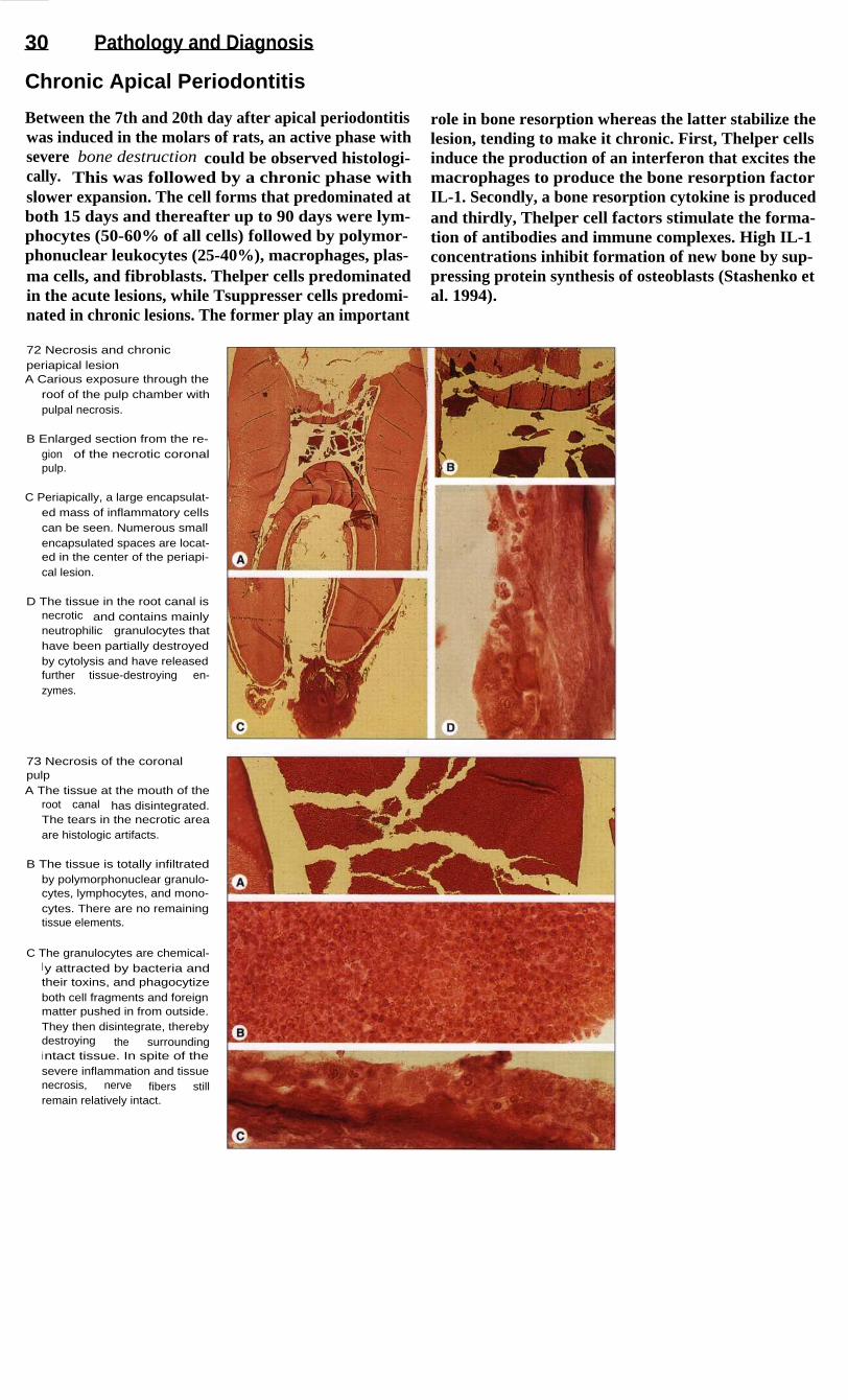
30
Pathology and Diagnosis
Chronic Apical Periodontitis
Between the 7th and 20th day after apical periodontitiswas induced in the molars of rats, an active phase withsevere bone destruction could be observed histologi-cally. This was followed by a chronic phase withslower expansion. The cell forms that predominated atboth 15 days and thereafter up to 90 days were lym-phocytes (50-60% of all cells) followed by polymor-phonuclear leukocytes (25-40%), macrophages, plas-ma cells, and fibroblasts. Thelper cells predominatedin the acute lesions, while Tsuppresser cells predomi-nated in chronic lesions. The former play an important
role in bone resorption whereas the latter stabilize thelesion, tending to make it chronic. First, Thelper cellsinduce the production of an interferon that excites themacrophages to produce the bone resorption factorIL-1. Secondly, a bone resorption cytokine is producedand thirdly, Thelper cell factors stimulate the forma-tion of antibodies and immune complexes. High IL-1concentrations inhibit formation of new bone by sup-pressing protein synthesis of osteoblasts (Stashenko etal. 1994).
72 Necrosis and chronicperiapical lesionA Carious exposure through the
roof of the pulp chamber withpulpal necrosis.
B Enlarged section from the re-gion of the necrotic coronalpulp.
C Periapically, a large encapsulat-ed mass of inflammatory cellscan be seen. Numerous smallencapsulated spaces are locat-ed in the center of the periapi-cal lesion.
D The tissue in the root canal isnecrotic and contains mainlyneutrophilic granulocytes thathave been partially destroyedby cytolysis and have releasedfurther tissue-destroying en-zymes.
73 Necrosis of the coronalpulpA The tissue at the mouth of the
root canal has disintegrated.The tears in the necrotic areaare histologic artifacts.
B The tissue is totally infiltratedby polymorphonuclear granulo-cytes, lymphocytes, and mono-cytes. There are no remainingtissue elements.
C The granulocytes are chemical-ly attracted by bacteria andtheir toxins, and phagocytizeboth cell fragments and foreignmatter pushed in from outside.They then disintegrate, therebydestroying the surroundingintact tissue. In spite of thesevere inflammation and tissuenecrosis, nerve fibers stillremain relatively intact.
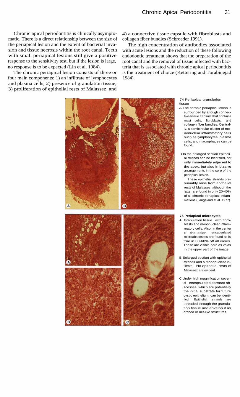
Chronic Apical Periodontitis
31
Chronic apical periodontitis is clinically asympto-matic. There is a direct relationship between the size ofthe periapical lesion and the extent of bacterial inva-sion and tissue necrosis within the root canal. Teethwith small periapical lesions still give a positiveresponse to the sensitivity test, but if the lesion is large,no response is to be expected (Lin et al. 1984).
The chronic periapical lesion consists of three orfour main components: 1) an infiltrate of lymphocytesand plasma cells; 2) presence of granulation tissue;3) proliferation of epithelial rests of Malassez, and
4) a connective tissue capsule with fibroblasts andcollagen fiber bundles (Schroeder 1991).
The high concentration of antibodies associatedwith acute lesions and the reduction of these followingendodontic treatment shows that the preparation of theroot canal and the removal of tissue infected with bac-teria that is associated with chronic apical periodontitisis the treatment of choice (Kettering and Torabinejad1984).
74 Periapical granulationtissueA The chronic periapical lesion is
surrounded by a tough connec-tive-tissue capsule that containsmast cells, fibroblasts, andcollagen fiber bundles. Central-l y, a semicircular cluster of mo-nonuclear inflammatory cellssuch as lymphocytes, plasmacells, and macrophages can befound.
B In the enlarged section epitheli-al strands can be identified, notonly immediately adjacent tothe apex, but also in bizarrearrangements in the core of theperiapical lesion.
These epithelial strands pre-sumably arise from epithelialrests of Malassez, although thel atter are found in only 20-40%of all chronic periapical inflam-mations (Langeland et al. 1977).
75 Periapical microcystsA Granulation tissue with fibro-
blasts and mononuclear inflam-matory cells. Also, in the centerof the lesion, encapsulatedmicroabscesses are found as istrue in 30-60% off all cases.These are visible here as voidsi n the upper part of the image.
B Enlarged section with epithelialstrands and a mononuclear in-filtrate. No epithelial rests ofMalassez are evident.
C Under high magnification sever-al encapsulated dormant ab-scesses, which are potentiallythe initial substrate for futurecystic epithelium, can be identi-fied. Epithelial strands arethreaded through the granula-tion tissue and envelop it asarched or net-like structures.

32
Pathology and Diagnosis
Chronic Apical Periodontitis and Radicular Cysts
Figures pertaining to the incidence of radicular cystsvary from 6 to 55%. Based upon a study of serial sec-tions, the incidence is around 15% (Nair 1995).
In one clinical-histologic study of 230 root tipbiopsies where periapical radiolucencies and clinicalsymptoms were present, only 14 cysts (6%) were con-firmed (Block et al. 1976).
The chronic periapical lesion is usually asymptoma-tic. Occasionally the tooth feels slightly elongated. Itmay be tender to percussion, and in 20% of casesfistulae can appear (Mortensen et al. 1970).
On the radiograph, chronic apical periodontitis ap-pears as a round or oval radiolucency that is usuallysharply demarcated. Sometimes a diffuse boundary isobserved. Average-sized radicular cysts are indistin-guishable from chronic periapical lesions. The percen-tage of radiolucencies that represent cysts rises amonglesions larger than 10 mm, although even among radio-lucencies that are 10-15 mm in diameter, less than 50%are likely to be cysts. Only a computer tomographicstudy can provide the differential diagnosis (Trope etal. 1989).
76 Fistula and radiographicperiapical lesionI n approximately 20% of cases ofchronic apical periodontitis andapproximately 10% of radicularcysts, a fistula occurs labial to thealveolar process. In the photo-graph a gutta-percha point, insert-ed to assist in the radiographici nterpretation, can be seen.
Right: This radiograph shows analmost plum-sized periapicalradiolucency as well as the insert-ed gutta-percha point.
77 Root canal preparationLeft: Because the central as wellas the lateral incisor give a negati-ve response to the sensitivity testand both are tender to percussion,the root canals of both teeth areprepared. The working lengths aremeasured radiographically. Over-i nstrumentration must be avoidedwhere there is apical resorption.
Right: Much of the infected tissueis removed with Hedstrom filesbefore the working length is de-termined.
78 Interim dressingOnce the canals have been fullyprepared they are given a final irri-gation, dried, and packed with athin mix of calcium hydroxide andwater using paper points as plug-gers. This is left in place for atleast 3 and a maximum of 6months.
Right: The root canals are instru-mented with Hedstrom files andK files and irrigated with a 1%sodium hypochlorite solution.
Chronic Apical Periodontitis and Radicul ar Cysts 33
Recently, a differentiation has been made betweenthe apical true cyst, which has a completely enclosedhollow space, and the pocket cyst, the lumen of whichis continuous with the root canal. Out of of 256 peri-apical lesions 9% were classified as true cysts and 6%as pocket cysts (Nair et al. 1995).
The existence of two different classes of radicularcysts and the inability to clearly distinguish a cyst fromchronic apical periodontitis clinically or radiographi-cally have therapeutic implications.
The treatment of periapical lesions consists ofpreparing the root canal and creating a bacteria-proofseal. Because no clear differential diagnosis basedupon radiographs can be made, and because the histo-logic status is unknown, periapical lesions are firsttreated in the conventional manner. Periapical pocketcysts will usually heal, where as true cysts will seldomrespond successfully to conventional treatment (Nair etal. 1993).
79 Clinical monitoringAfter 3 months the interim dressingis changed. The fistula is no longervisible. There are no further signsthat would indicate persistence ofthe periapical inflammation.
Left: After a further 3 months, thei nterim dressing is flushed out withsodium hypchlorite solution and aradiograph is taken to evaluate thedissolution of the periapical lesionas well as the fit of the gutta-percha points.
80 Root canal obturationLeft: After the sealer-coated gutta-percha points are inserted up tothe reference points and the firstl ateral condensation is accom-plished, a radiograph is taken sothat any overextension of the fill-ing, in the case of possible peri-apical resorption, can be detectedand corrected early in the proce-dure.
Right: The root canal filling iscompleted by lateral condensationof additional gutta-percha points.
81
Radiographic monitoring ofthe results of conservativetreatmentI n the follow-up radiograph 2 yearsl ater, there is further bony regene-ration around the periapical lesionwith ingrowth of bone trabeculae.However, a small radiolucency isstill visible at the apex of the leftl ateral incisor.
Left: Radiographic follow-up of theroot canal fillings 1 year after thebeginning of treatment. The peri-apical lesion is noticeably reducedi n size.

34
Path ology and Diagnosis
Radicular Cysts
The radicular "true" cyst is defined as a chronic peri-apical inflammation surrounding a closed, epithelium-lined space. It arises from chronic apical periodontitisin three developmental phases. In the first, or initiation,phase, dormant epithelial rests of Malassez begin toproliferate. During the second phase an epithelium-lined space is formed, and in the third phase cysticgrowth occurs as the result of osmotic and resorptionstimulating factors (Nair 1995).
An established radicular cyst is composed of aconnective-tissue capsule, a subepithelial zone ofinflammatory infiltrate, an epithelial cyst lining, anda cyst lumen. The lumen contains, in addition tosloughed necrotic epithelial cells, cholesterol crystals,inflammatory cells, and remnants of resorbed bonetissue. The cyst wall is a stratified squamous epithe-lium permeated by granulocytes, macrophages, andlymphocytes. The subepithelial zone contains T and Blymphocytes and plasma cells (Schroeder 1991).
82 Formation and componentsof a radicular cystA Cholesterol crystals are located
i n the lumen of an establishedradicular cyst, surrounded bythe epithelial lining and thesubepithelial zone with infiltra-tion of inflammatory cells. Theconnective-tissue capsule con-tains fibroblasts and collagenfiber bundles, and is closelyconnected with the periapicalperiodontal fibers.
B The epithelial cyst wall is madeup of stratified squamous epi-thelium with no stratum corneumand is a minimum of 20 and amaximum of 50 cell layers' thick.
C Within the cystic cavity a brown-ish-yellow l i quid containingcholesterol crystals and necro-tic tissue is found. Polymor-phonuclear granulocytes andmononuclear leukocytes arealso evident.
83 Contents of the cysticl umenA The organic components within
the cystic cavity liquify, the in-gredients of which can scarcelybe identified any longer; this isinterspersed with neutrophilicgranulocytes and individuallymphocytes that indicate acuteexacerbation with infection andinflammation.
B Remnants of lamellar bonewithin the cystic cavity testify tothe resorptive capability of thecystic tissue.
C Multinuclear giant cells are alsoevidence of a possible foreign-body reaction; neighboring plas-ma cells produce antibodies,principally IgG and IgA, and to alesser extent, IgM and IgE.
D The majority of the lymphocytesare T cells, with fewer B cells ina ratio of 3:1.

35
Examination and Diagnosis
The patient who comes to the dental office with a painful tooth introduces a diagnostic andtherapeutic challenge into an otherwise planned and orderly schedule. The goal of endodonticintervention is to remove the cause of the pain. The correct diagnosis can be arrived at throughconsideration of the subjective and objective symptoms, and treatment appropriate to the diagno-sis can then be begun. Because of anatomic limitations, however, diseased pulpal and periapicaltissues cannot be directly inspected in vivo. These limitations have led to the development ofindirect diagnostic methods. In addition to clinical findings, the subjective phenomenon of painis an essential criterion for evaluating the pathologic condition of the pulp, even though there isno direct correlation between the histologic condition of the pulp and the various symptoms,especially pain. When pain occurs, it must be determined if it is dental in origin or if it is radiat-ing from neighboring organs.
The examination of the patient includes a medical anddental history, extraoral and intraoral inspection, andpossible differential diagnoses. The patient must pro-vide information on past and present medical anddental diseases.
There are no medical contraindications to perform-ing root canal treatment, although medical conditionsand the patient's psychological state must be taken intoconsideration. The medical history should reveal allmedical conditions and medications that might influ-ence endodontic treatment or that might themselves beaffected by the dental procedures. The existence ofsystemic diseases such as rheumatic fever, coronaryheart disease, high blood pressure, and diabetes mustbe determined from the history. Patients at risk ofbacterial endocarditis must be covered by prophylacticantibiotics.
The dental history includes data important for thetreatment plan. Within the scope of a dental history, thepatient's history of pain must be explored. The deve-lopment of the present complaint is recorded briefly inthe patient's own words. The questions related to den-tistry should bring out information on any past trauma-tic injuries, and any connections with earlier dentaltreatments. The patient should report any swelling orspontaneous drainage, and whether pain is induced bypressure or chewing. The history of pain must be spe-cific with regard to the type of pain, the time at whichpain occurs, what initiates and relieves it, its location,and whether it radiates into other areas. There are alsoquestions concerning bleeding or suppuration from thegingivae, food impaction between the teeth, andincreased tooth mobility.
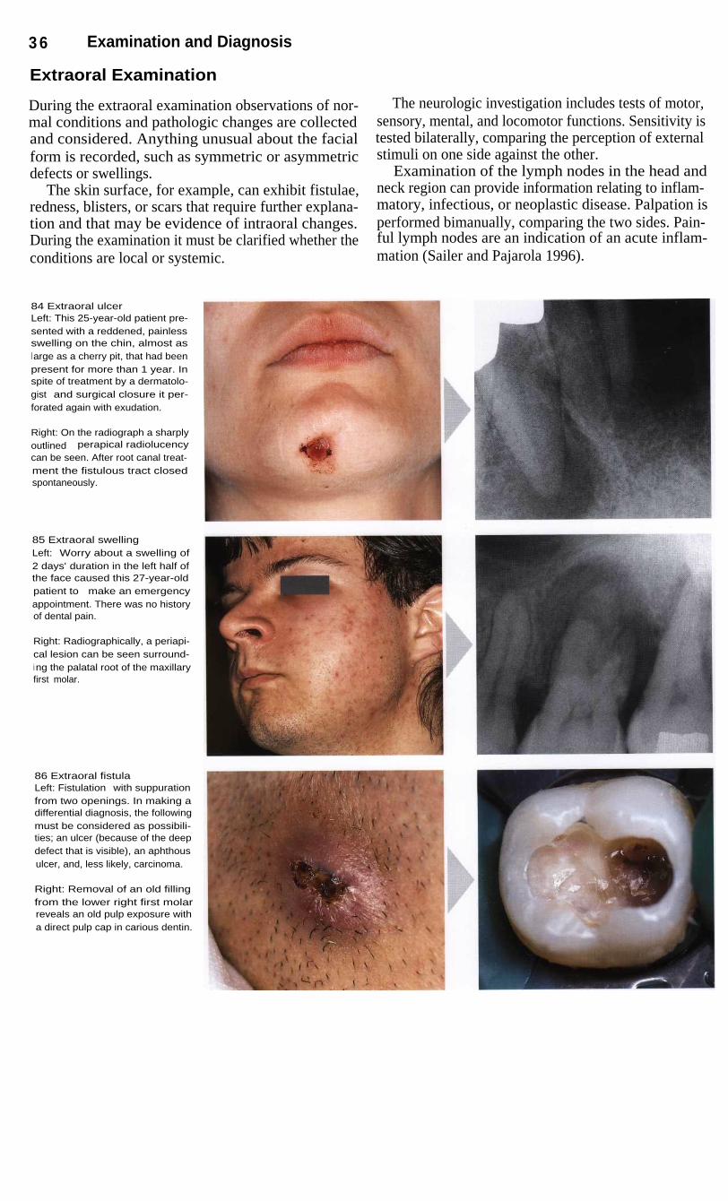
3 6
Examination and Diagnosis
Extraoral Examination
During the extraoral examination observations of nor-mal conditions and pathologic changes are collectedand considered. Anything unusual about the facialform is recorded, such as symmetric or asymmetricdefects or swellings.
The skin surface, for example, can exhibit fistulae,redness, blisters, or scars that require further explana-tion and that may be evidence of intraoral changes.During the examination it must be clarified whether theconditions are local or systemic.
The neurologic investigation includes tests of motor,sensory, mental, and locomotor functions. Sensitivity istested bilaterally, comparing the perception of externalstimuli on one side against the other.
Examination of the lymph nodes in the head andneck region can provide information relating to inflam-matory, infectious, or neoplastic disease. Palpation isperformed bimanually, comparing the two sides. Pain-ful lymph nodes are an indication of an acute inflam-mation (Sailer and Pajarola 1996).
84 Extraoral ulcerLeft: This 25-year-old patient pre-sented with a reddened, painlessswelling on the chin, almost asl arge as a cherry pit, that had beenpresent for more than 1 year. Inspite of treatment by a dermatolo-gist and surgical closure it per-forated again with exudation.
Right: On the radiograph a sharplyoutlined perapical radiolucencycan be seen. After root canal treat-ment the fistulous tract closedspontaneously.
85 Extraoral swellingLeft: Worry about a swelling of2 days' duration in the left half ofthe face caused this 27-year-oldpatient to make an emergencyappointment. There was no historyof dental pain.
Right: Radiographically, a periapi-cal lesion can be seen surround-i ng the palatal root of the maxillaryfirst molar.
86 Extraoral fistulaLeft: Fistulation with suppurationfrom two openings. In making adifferential diagnosis, the followingmust be considered as possibili-ties; an ulcer (because of the deepdefect that is visible), an aphthousulcer, and, less likely, carcinoma.
Right: Removal of an old fillingfrom the lower right first molarreveals an old pulp exposure witha direct pulp cap in carious dentin.

Intraoral Examination
37
Intraoral Examination
The visual intraoral examination includes a search forswelling, redness, fistulation, suppuration, periodontaldisease, dental caries, discolorations, loose teeth,fillings, and the overall condition of the dentition.Some or all of the following examination proceduresshould be employed: palpation, percussion, toothmobility test, periodontal examination, occlusal analy-sis, cracked tooth test, sensitivity test, transillumina-tion, selective anesthesia test, and a radiographic sur-vey.
Tenderness to percussion of an affected tooth is asure sign of an early pathologic conditon. The questionto be answered is whether the cause is periodontal orendodontic or perhaps occlusal trauma in combinationwith marginal gingivitis. Apical palpation over the roottips in the vestibule can reveal tenderness to pressure,inflammatory infiltration, swelling, or frank fluctuati-on. A fistula can be diagnosed if exudate comes out ofthe tissue upon light pressure applied in the area (Beer1992 b).
87 Caries and fillingLeft: Stained fillings must bechecked for marginal imperfec-tions. The inadequate oral hygienealso suggests bacterial penetra-tion.
Right: A maxillary lateral incisorwith deeply penetrating caries.This condition was present at theclinical examination, and the pati-ent's oral hygiene is good. Pre-sumably the carious destructionwas started by plaque accumula-tion in a foramen cecum (lingualpit).
88 Fistulae and perforationsLeft: Mandibular incisor region ina 32-year-old patient with a defec-tive full crown restoration coinci-dent with inadequate oral hygiene.The cause of the facial perforationi s tissue reaction to corrosion ofthe core buildup.
Right: In addition to discolorationof the crown of the tooth, the swell-i ng and fistulation are furtherevidence of a necrotic pulp withperiapical involvement. Even thoughthere is no pain, a meaningfuldiagnosis is possible.
89 Tooth discolorationLeft: Severe discoloration of a ma-xillary anterior tooth. The radio-graph reveals a root canal fillingthat is insufficient and extends intothe coronal cavity.
Right: This tooth continued to bepainful after emergency excavationof the caries. The cavity has beenfilled with a material that takes upmoisture during the setting reac-tion, bringing about pulp damage.

38
Examination and Diagnosis
Sensitivity Tests
Electric or thermal sensitivity tests provide informationon whether the pulp tissue is severely damaged or not.Cold tests are the most informative of these. As a rule,a precise differentiation between a clinically soundpulp and reversible or irreversible pulpitis by this testalone is not possible, because intact nerve tissue can befound even in areas of severe inflammation and tissuenecrosis. It is even possible to perform a positive sen-sitivity test in the presence of a small periapical radio-lucency (Lin et al. 1984).
Nevertheless, a test of the pulp's sensitivity, whichhas erroneously been called a "vitality test", is helpfulin differentiating pulp diseases. The cold test with car-bonic acid snow (dry ice) has great advantages over allother sensitivity tests. Because of the insulating layerof vapor that the CO 2 snow gives off at temperaturesabove 0 °C, this test is harmful to neither the tooth northe surrounding tissue. Enamel crazing will not occuruntil after a 2-minute exposure (Peters et al. 1986).
90 Cold testApplication of cold for 4 secondsl owers the temperature to between26 and 30 °C, eliciting pain. Withinthe pulp the temperature is lower-ed by only 0.2 degrees (Lutz et al.1 974).
Cones of ice reach temperaturesas low as -20 °C; Frigen (US equi-valent Freon) from spray contain-ers applied to a tooth surface bymeans of a pellet can lower thetemperature to minimum of -40 °C.
Right: Compressed carbonic acidsnow reaches -70 °C.
91
Electric pulp testThe electric sensitivity test is simpleto use and usually reliable. Thetooth surface must be dry. The tipof the pulp tester is moistened.Gloves can result in false resultsbecause of their insulating effect.The easiest way to create a closedelectrical circuit is to have thepatient's hand touch the metal partof the pulp tester.
Right: Electric pulp tester withadjustable current intensity.
The electric pulp test is based upon the uniquerelative conductivity of dental hard tissues. In the testapparatus, the series of voltage-regulated stimulatingimpulses is so tuned to the impedance of the tooth thatshould there be an unintended bypass circuit throughthe mucous membrane, the electric current is interrupt-ed and a false positive reading is avoided. The moist-ened electrode, usually made of conducting rubber, isrested upon the dry tooth surface. The electrical circuitflows from the handpiece through the body of the op-erator to the body of the patient via a mouth mirror.
The test can be used in both deciduous and perma-nent teeth. Young teeth with wide open apical forami-na do not yet have a fully developed sensitivity, thusfalse negative readings may occur. Furthermore, follow-ing trauma the sensitivity test may give a negativeresult for days or even several weeks. The electric pulptest cannot be used on teeth with metal crowns becauseof short circuiting, or with ceramic crowns because oftheir insulating effect. False negative readings canoccur where extensive caries is present. The test is con-traindicated in patients with cardiac pacemakers.

Clinical Examination and Selection of Therapy
Clinical Examination and Selection of Therapy
39
The initial diagnosis can be supplemented and finalizedby means of a whole series of tests. Extraoral swellingor discoloration may be obvious and can be differen-tiated as soft, firm, hard, and/or painful throughpalpation. The condition of the lymph nodes, whetherunilateral or bilateral, provides information on inflam-matory processes. Inside the mouth, the appearance ofthe teeth (including discolorations) and of the gingiva,as well as palpation of the roots in the vestibule andpalate all contribute toward a differential diagnosis.
In addition to the radiograph, transilluminationmakes it possible to detect caries, fractures, and otherabnormalities. Selectively anesthetizing a single toothcan help identify which tooth is diseased. Furthervaluable information for a differential diagnosis can begained through percussion to determine if a tooth istender to vertical or horizontal tapping. Biting on awooden tongue blade can reveal fractures and fissuresthrough pain elicited by application or release ofpressure.
92 PalpationDigital palpation of soft and hardtissues provides important infor-mation for a diagnosis.
Left: Extraoral bimanual palpationof the lymph nodes.
Center: The root surface is palpat-ed all the way to the apex in thevestibule, and the patient is askedto report any unusual sensations.
Right: In the palate the roots andthe overlying tissues are palpated.
93 Percussion and biting testSensitivity of a tooth to tapping is asign that periapical inflammation ispresent. Fractures can also bedetected through percussion or thebiting test.
Left: The response of a tooth tovertical percussion is always com-pared with the response of theteeth immediately adjacent to it.
Center: Horizontal percussion.
Right: Biting test using a woodentongue blade. Pain in response tobiting pressure is always evidenceof a tooth fracture.
A compilation of the results of these examinationprocedures, combined with clinical experience, make itpossible to identify a clinically healthy pulp, reversiblepulp disease, irreversible pulpitis, or pulp necrosis, andto select the appropriate treatment. The clinicallyhealthy pulp is characterized by absence of pain, whilewith reversible pulpitis the pain can be initiated bycold. In both of these cases the caries has not yet reach-ed the pulp. With irreversible pulpitis pain occurs spon-taneously, there may still be a positive response to thesensitivity test, and the results of the percussion testmay be either negative or positive.
If there is a history of short or long-lasting conti-nuous pain, the caries must be completely removed asa diagnostic measure. Allowing even small amounts ofsoftened dentin to remain in the cavity floor is abso-lutely contraindicated. If the pulp becomes exposedduring excavation of caries an emergency pulpitistreatment is carried out. Under local anesthesia thecoronal pulp is sharply removed to the entrance of theroot canal, the entrance is covered with a cotton pelletand the cavity is tightly sealed. At a second appoint-ment the root canal is instrumented and an interimdressing and temporary filling are placed.
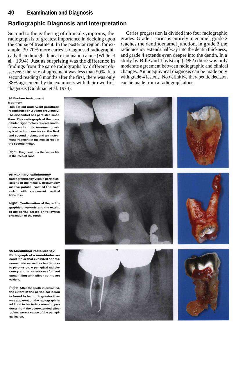
40
Examination and Diagnosis
Radiographic Diagnosis and Interpretation
Second to the gathering of clinical symptoms, theradiograph is of greatest importance in deciding uponthe course of treatment. In the posterior region, for ex-ample, 30-70% more caries is diagnosed radiographi-cally than through clinical examination alone (White etal. 1994). Just as surprising was the difference infindings from the same radiographs by different ob-servers: the rate of agreement was less than 50%. In asecond reading 8 months after the first, there was only88% agreement by the examiners with their own firstdiagnosis (Goldman et al. 1974).
Caries progression is divided into four radiographicgrades. Grade 1 caries is entirely in enamel, grade 2reaches the dentinoenamel junction, in grade 3 theradiolucency extends halfway into the dentin thickness,and grade 4 extends even deeper into the dentin. In astudy by Bille and Thylstrup (1982) there was onlymoderate agreement between radiographic and clinicalchanges. An unequivocal diagnosis can be made onlywith grade 4 lesions. No definitive therapeutic decisioncan be made from a radiograph alone.
94 Broken instrument
fragment
This patient underwent prostheticreconstruction 2 years previously.
The discomfort has persisted since
then. This radiograph of the man-dibular right molars reveals inade-
quate endodontic treatment, peri-apical radiolucencies on the first
and second molars, and an instru-
ment fragment in the mesial root ofthe second molar.
Right: Fragment of a Hedstrom filein the mesial root.
95 Maxillary radiolucency
Radiographically visible periapicallesions in the maxilla, presumably
on the palatal root of the first
molar, with concurrent verticalbone loss.
Right: Confirmation of the radio-
graphic diagnosis and the extent
of the periapical lesion followingextraction of the tooth.
96 Mandibular radiolucency
Radiograph of a mandibular se-cond molar that exhibited sponta-
neous pain as well as tenderness
to percussion. A periapical radiolu-cency and an unsuccessful root
canal filling with silver points areevident.
Right: After the tooth is extracted,the extent of the periapical lesion
i s found to be much greater than
was apparent on the radiograph. Inaddition to bacteria, corrosion pro-
ducts from the overextended silverpoints were a cause of the periapi-
cal lesion.

Radiographic Diagnosis and Interpretation 41
With a mineral content of 52% in cortical bone,there must be a 6.6% loss of bone mineral in order forthe lesion to become radiographically visible. Lesionsin the spongiosa of the mandible can be masked by thecortical layer of bone (Bender 1982). Only with de-struction of the transition zone between spongy andcortical bone, which shows no clear anatomic demar-cation, does a radiographic change become visible dueto the alterations in the trabecular bone structure(Shoha et al. 1974, van der Stelt 1985).
Lesions in the periapical region of the mandible donot become recognizable until half the thickness of thebuccal cortical bone has been eroded. Because no oneX-ray tube alignment is superior to any other in regardto revealing a lesion, Marroquin et al. (1995) recom-mend the orthoradial projection. Only if the findingsfrom this angle are unclear should an additional eccen-tric radiograph be taken. In spite of the problematicinterpretation of the apical radiograph, to forego thisuseful diagnostic tool would be unthinkable.
97 Alignment of X-raysRay directions for orthoradial, me-sial eccentric, and distal eccentricprojections. An eccentric projec-tion is usually necessary to sup-plement an orthoradial projectionwhen certain structures of bone ortooth are to be represented.
I n the mesial eccentric radiogra-phic technique the central ray isdirected more from the mesial. Inthe distal eccentric technique it isdirected more from the distal.
A distinction is also made be-tween apical and periodontalradiographic techniques, becausethe sharpest image and the leastdistortion are produced where thecentral ray passes through the tis-sue. In practice, however, one can-not forego making the image of thecrown and root on the same film. Ifin the apical technique the centralray is directed toward the apex, theimage of the alveolar crest will beof secondary significance.
98 Eccentric radiographLeft: The radiograph taken with or-thoradial ray alignment shows onlyone root canal in each premolar.Clinically, however, an additionalsecond canal was found in bothteeth. This can be explained byroot structures being superimpos-ed on the radiograph.
Right: Two separate root canalsare revealed in each tooth whenan eccentric ray alignment is used.

42
Examination and Diagnosis
Radiography in Endodontics
The radiograph is an indispensable aid in endodontics,not only in treatment planning but also during treat-ment and in monitoring the results of treatment. Theradiographs must be of high quality: films with poorcontrast and severe distortion are as worthless as noinformation at all. An example is a film that fails toshow the root tips. The radiograph must show a sharpoutline of the root and reveal the tooth length and thenumber of roots and canals as accurately as possible.The extent of the pulp chamber and the curves in theroots and canals should also be discernible. In addition,
the diagnostic radiograph must reveal any informationon calcifications, hard-tissue deposits, internal or ex-ternal resorption, the extent and origin of periapicallesions, and perforations and fractures.
Because radiographs are two-dimensional represen-tations of three-dimensional dental structures, the diag-nostic interpretation is limited. Magnifying loupes arerecommended for a more exact interpretation (Gulde-ner and Langeland 1993).
99 Diagnostic radiographThe first radiograph does not showall of the lower second molar thatis to be treated, but it does showdefective fillings with secondarycaries on all three teeth. The cavi-ty on the second molar has pene-trated the pulp, causing pulpalnecrosis.
100 First measurementradiographTo avoid overextending the instru-ments during preparation of thecanals and transporting bacteriafrom the infected coronal portionof the pulp apically, a radiographis taken for orientation and meas-urement.
Right: Clinical view with the distalfile inserted.
101 Working-lengthradiographDetermination of the workingl ength after insertion of files intothe three root canals. Because ofperiapical resorption, the distali nstrument is overextended, requir-i ng adjustment of the length. Thelack of sharpness and poor qualityof the radiograph means that aclear determination of the workinglength is difficult.
Right: I ntraoral view during thesubsequent enlargement of theroot canals.

Radiography in Endodontics
43
During root canal treatment additional radiographsare necessary, their number depending on the specificsituation. Besides the diagnostic radiograph, the mea-suring radiograph is essential. Yet another image withthe master points in place allows a recheck of the prep-aration depth and helps avoid overfilling or underfill-ing of the root canals. The radiographs of the complet-ed case and at the 1-year recall reveal the quality ofcanal obturation and any indications for surgical inter-vention.
The dentist cannot claim a patient's refusal to haveradiographs taken as a defense in a lawsuit if radio-graphs were a necessary part of the diagnosis or treat-ment. Neglecting to take preoperative radiographs canresult in a reversal in the burden of proof if there arerelated consequences, such as treatment of the wrongtooth. The patient no longer has to prove that treatmentwas faulty; rather the dentist must prove that the treat-ment was correct (Hulsmann 1995).
102 Master point radiographAfter enlargement of the threecanals, three gutta-percha pointsthe same size as the master filesare inserted, and their exact posi-tion on the radiograph is measur-ed. The lack of sharpness of theradiograph does not permit a cleari nterpretation.
Left: The clinical view shows thegutta-percha points with the work-i ng lengths marked by indenta-tions from pliers.
103
Filling the root canalsAfter removal of the three gutta-percha points the root canals arethoroughly dried and are ready forthe final root canal filling.
Left: I ntraoral view during filling ofthe canals. The working length istransferred to the finger spreaderby means of a silicone stop. Thegutta-percha is condensed lateral-ly with the finger spreader.
104 Radiographic evaluationof the root canal fillingAfter the root canal filling is com-pleted, the result is evaluated ra-diographically. In spite of the meas-urement of the working lengthand its monitoring before conden-sation, a slight apical overexten-sion of the filling is visible on themesial root. Even if there are nosymptoms, a recall radiograph isi ndicated after 1 year.

44
Examination and Diagnosis
Digital Radiographic Technique
Since the discovery of X-rays, radiographs have play-ed a more important role in dentistry than photographicprocesses. With the rapid developments in semicon-ductor technology, however, electronic procedures forrecording images now permeate all fields of medicine.For this new type of imaging the general term "digitalradiography" has been widely adopted.
Intraoral Systems
Digital technology made its entry into dentistry 10years ago in the form of the intraoral sensor. Diagnos-tic radiation is always invasive; this sometimes resultsin the patient refusing radiographs or the dentist, inhaste to deliver treatment, failing to take them. How-ever, it is precisely because of the difficult anatomicrelationships in the region of tooth roots that the treat-ment time and the success of endodontic proceduresbear a positive correlation with the number of (reason-able) radiographs taken.
Advantages of the new digital radiographic techni-que are the reduced radiation exposure (80% less thanwith the best conventional periapical film), the imme-diate availability of the image, an image presentationthat can be adapted to suit the problem, the lack of a
need for processing materials, electronic archiving, andthe ability to connect with data networks both insideand outside the office.
A digital image is formed when the image sensorfeeds information into a computer point by point, andeach point is coordinated with one of, for example,1024 (10 bit) to 4096 (12 bit) possible intensity grada-tions depending upon the radiation intensity registeredthere. This scale coordination or digitization is the pre-requisite for image processing in the computer.
Systems for intraoral dental radiographs can be clas-sified as either direct or indirect. For a direct image asemiconductor camera in the patient's mouth trans-forms the distribution of roentgen rays into an electro-nic signal that is transmitted to the computer over acable and immediately appears on the monitor. In theindirect process, a so-called storage phosphor platestores the image for transfer to the computer; it has nocable connection to the computer. After exposure it isread by a scanner. The appearance of the image isdelayed by the time required for scanning.
105
Sensor of an intraoraldigital systemThe accumulator foil of the GendexDigora System (center) is sealed ina foil envelope before it is used.The image surface of this foil cor-responds to a dental film (left) andi s wider than that of a CCD sensor(right).
The semiconductor camera (CCDcamera) as an example of a directi maging unit is shown on the right(Sirona).
Contrast EnhancementContrast is a measure of the difference in brightnessbetween neighboring areas of the picture. The humaneye has a threshold value at which the variations inbrightness of different areas of an image can first be re-cognized. Subsequently, the contrast can be increasedelectronically as desired.
Positive-Negative RepresentationFrom the negative image a positive picture can be pro-duced electronically. This corresponds more closely towhat the eye is accustomed to seeing than does theusual negative image on a radiograph.
False Color RepresentationThe rays falling upon the sensor can not only be trans-formed into shades of gray but also into differentcolors. The effect of this random color arrangementdepends upon the translating table used.
Millimeter GridWith the stroke of a key, a grid with 1-mm spacing,relative to the surface of the sensor, is made to appearon the monitor screen.
This aids in estimating lengths, but may not be usedas a substitute for the object ruler, however.

Digital Radiographic Technique
45
ResolutionResolution is expressed in line pairs per millimeter(Lp/mm). The higher the resolution, the smaller the de-tails that can be distinguished in the picture. A resolu-tion of at least 6 Lp/mm is necessary for clinical use.However, since complex filters generally make theimage more coarse, higher resolution capability is de-sirable.
DynamicThe dynamic indicates the number of possible gradesof intensity or number of gray scales that can be digi-tized. A greater dynamic with at least 1024 shades ofgray helps to avoid overexposure and underexposure.High dynamic combined with high resolution providesa greater choice for application of filters.
FiltersFilters serve to distinguish more clearly fine variationsin the structure of the object that are indistinguishableto the eye in the original image.
The selection ranges from simple filters (posi-tive-negative representations, contrast enhancers, rain-bow colors) to more involved processes such as sup-pression of occasional variations in intensity (noise),
sharpening the image in the corner areas, or even creat-ing the appearance of images in relief.
In general, the more involved filters make the imageresolution more coarse and, if used uncritically, canmake important regions disappear of create images ofstructures that do not exist in the object.
Apart from the "good feeling" of the operators, therehave been few scientifically based presentations on theusefulness of different filters. The relief filter, however,seems to be very helpful in endodontic procedures.
Projection AngleDigital technology has not changed the fundamentalsof producing an image. With the intraoral procedurethe objective now as ever is to obtain the best possiblerepresentation of the individual teeth. The old rules stillapply to projection angles. Positioning, at least with theCCD sensor, is made easier by a film holder that is tobe used with the right-angle technique, which more-over has advantages for producing quality images. Thelong cone technique produces a geometrically superiorprojection with the digital systems.
106 Digital measurementpicturePositive image
Left: Standard image
107 Digital measurementpictureRelief image
Left: Contrast enhancement
Collection C. Benz

46
Examination and Diagnosis
Uses of Digital Radiography
The digital technique has not yet revolutionized theviewing habits in the field of diagnostic radiography. Itcan, however, provide a completely new impetus tomeeting the main challenges in endodontics. Number-ed among these challenges is the representation of athree-dimensional tooth such that the disclosure of theposition and size of relevant structures is possible. Finevariations in the image, such as small-sized files in theroot canals of maxillary molars, are more readily iden-tified. The digital image, like X-ray film, only recordsa two-dimensional shadow of the object.
Gathering information in the third dimension iseasier with a digital CCD system than a film or a stor-age phosphor plate. The digital image can be seen im-mediately and the position of the sensor that produced itcan be maintained. Starting from this position, other an-gulations can be selected and multiple digital radio-graphs made without exceeding the radiation dose ofone conventional radiograph. The representation of finevariations in the object should be the showpiece of thedigital technique. That this is not yet the case is the faultof an insufficient number of gray scales in the system.
108 Digital follow-upradiograph (Sidexis)Standard image
Right: Positive image
109
Digital follow-upradiograph (Sidexis)Enhanced contrast
Right: Relief image
Collection C. Benz
A diagnostic radiograph must use an orthoradialprojection, i. e. the parallel technique, so that theproximal surfaces stand out clearly and distancesparallel to the tooth's main axis are reproduced withrelative accuracy. On a measuring radiograph the ima-ges of canals lying in the same faciolingual planeshould be separated. With mandibular molars this canbe done with a minimum of distortion by using a slight-ly distal-eccentric projection angle.
Also, in order to best display the tip of the instru-ment and the border between the radiographic apex andthe periodontal area, the sensor should be tipped sothat it diverges away from the long axis of the tooth
coronally. In this way root apices are more clearly visi-ble because the canal nearest the sensor will appearmore coronal than the canal farther from the sensor. Asystem that delivers a lower dose of radiation with eachexposure makes more exposures possible, varying theprojection angle until the goal is reached. Instrumentsdown to size 08 should be identifiable. If these instru-ments cannot be seen, the cause usually lies with errorsin the projection. In order to avoid overlapped images,the shortest distance through the object is chosen, i. e.horizontal and vertical projection angles near 90°(Benz 1992).

47
Anatomy
The interior of a tooth, the endodontium, is to a large extent hidden from direct inspection by theoperator. Even passing roentgen rays through the tooth provides only limited clues to the structure.For this reason, much time and energy have been invested in research into the "normal" anatomyand the statistical incidence of different variations in form (review: Baumann 1995). It is hoped thatthis information will be helpful in the daily practice of endodontics. This research has alreadycreated awareress of the complexity of the root canal system, which is not simply a conical tube,but rather a branching system with a pulp chamber, primary canals, lateral canals (communicatingwith the periodontium), and accessory canals (multiple ramifications in the apical third of the root).This knowledge is a basic requirement for successful endodontic treatment. The theoretical pulpalanatomy that we expect to encounter, though, can only provide initial orientation because the actualsituation encountered during treatment always reveals new variations.
110 Three-dimensionalreconstructionBy means of computer reconstruc-tion based upon serial histologicsections, the root tips of a maxil-l ary molar have been reproducedas a three-dimensional lattice workwith a computer-generated surfa-ce. The outer contours of the toothare colored blue, the root canalsare vellow-oranae.
The first detailed systematic description of root
he filled the pulp space with vulcanized India rubbercanal anatomy found in the literature is by Carabelli
and then dissolved the surrounding tooth substance(1844). The same manner of representation with longi-
with 50% hydrochloric acid. This acid dissolutiontudinal and transverse sections in different planes is
preparation showed for the first time, and very impres-still used in modern textbooks (e. g., Cohen and Burns
sively, the complex branching of the pulp tissues and,1994). Some of these illustrations go back to the origi-
with it, the root canal system. Whereas the previousnal sections and serial sections (Black 1902; Miller
sections, slides, and drawings were only two-dimensio-1904). In addition to direct observation with the unaid-
nal, now for the first time it was possible to see a spa-ed eye and the microscope, the chemical dissolution
tial representation of the entire root canal system. Hessmethod has provided much valuable information. In
studied 2800 teeth of the permanent human dentitionthis process the tooth is opened, the pulp digested, and
and his student Zurcher (1922) studied deciduous teeth.the empty pulp space filled. The famous Swiss pulp re-
Together they gathered statistical data on the number ofsearcher Hess (1917) perfected this technique in which
canals and their ramifications.

48 Anatomy
Methods of Reproducing Root Canal Anatomy
Most techniques require the destruction of the tooth.However, at the beginning of the twentieth century thetransparency method was developed (Adloff 1913) inwhich the integrity of the tooth and the spatial relation-ships of the root canal and its outer contours werepreserved. Various substances (from colored gelatinand paraffin to silicone) were introduced into the pulpspace through an access opening, and the tooth wasthen made transparent by means of oil of cedar, benzol,or salicylic acid compounds.
The work of Vertucci (1974-1984) deserves specialconsideration. While histologic sections have longprovided information on the structure of the root canaland the pulp tissue, Meyer (1955-1970) set new stan-dards. From serial sections of all 16 types of permanentteeth he made 50x scale models of the apical canals(the last 6 mm of each) of 800 teeth by projecting thecircumference of the canals and building wax modelslayer by layer. This study further clarified the comple-xity of the pulp space, from then on called the rootcanal system (Meyer 1955 b, 1960).
111
Methods for visualizingthe anatomy of the root canals 1Left: Histologic longitudinal sec-tion through a devitalized premolar(Collection W. Ketterl).
Center: Transparency technique.An opening is made into the tooth,the pulp digested, and the spacefilled with stained (Berlin blue) ge-latin. The hard structure is madetransparent by soaking in methylsa I icylate.
Right: Wax recontruction of thepulp of a premolar based uponhistologic serial sections.
Awareness of the existence of large numbers oflateral canals and diverticula renders obvious the im-possibility of full preparation of all the branches duringroot canal treatment. A significant outcome of this isthe technique of combined chemical-mechanical prep-aration. Meanwhile, after radiographs began to be usedin laboratory studies, images in two planes becamestandard. Pineda and Kuttler (1972) performed what isprobably the largest in vitro study on over 4000 teeth.Their study covered the extent of branching and varia-tions in canals, roots, and apical deltas, and the influ-ence of age on their occurrence.
Hession (1977a-d) showed the shape of the rootcanal system radiographically before and after in vitrotreatment. The abundant range of research tools iscomplemented by in vivo radiographs, microradio-graphs, scanning electron microscopy (SEM), compu-ter reconstructions, monographs of individual cases,and many other aids (Baumann 1995). Subsequently,an immense body of facts has been accumulated andthese are presented in excellent didactic style in books,videos, slide series, reports, seminars, and demonstra-tions. This new information should be offered in furthereducation courses (Baumann 1994, 1995).
112
Methods for visualizingthe anatomy of the rootcanals IILeft: Macroscopic anatomy of amolar.
Center: A radiograph of the samemolar allows a look at the innerconfiguration of the root canalsystem.
Right: Sectioned teeth have longserved to help visualize the internalarchitecture of the pulp chamber.The SEM makes possible detailedinspection and to some extentcreates the effect of spatial depth.

Methods of Reproducing Root Canal Anatomy
Three-dimensional Computer Reconstruction
49
From a historical perspective we see a long tradition ofstriving to better describe the anatomy of the teeth. Re-cently, preparations of 20-pm-thick frozen sectionswere continuously recorded on videotape, producingdata to serve as the basis for computerized three-dimensional reconstructions. In a contour-based recon-struction only the surface outlines of the tooth and thecanals are used for input (Baumann et al. 1993 d,1994b). From this emerges a contour line, surface, orsolid body model that can be viewed from any desiredangle.
Newer, faster computers permit the use of all shadesof gray in a video image to create a volume-based re-construction (volume rendering). Through ray-tracing,isotropic voxels (points in space) are created in whichthe raw unaltered data is drawn upon for three-dimen-sional reconstruction (Baumann 1995, Bauman et al.1993 d).
Images are created that can be viewed, sectioned,colored, zoomed, or rotated in any desired plane. Thismakes possible views into the endodontic space thatwere previously unknown.
113 Contour-basedreconstructionIn the beginning of three-dimen-sional reconstruction by computer,most attention was usually given tothe contours of the object. By limit-ing the essential image content(here: outer shell of the tooth andthe canals) the data to be process-ed was greatly reduced. The dentinmantle of the tooth in Figure 112 isrepresented here in the surfacemode and the pulp in solid bodymode. The cutaway allows a viewof the tooth's interior. The specialselection of colors increases theimpression of solid form in thereconstruction.
114 Volume renderingA sequence of histologic serialsections is transferred to a compu-ter as a digitized series of images.With special software, all shades ofgray in the video image are drawnupon to create a spatial recon-struction of the data set. The ima-ges thus generated are aligned bycoordinating the colors instead ofthe gray shades to allow observa-tion in any desired plane.
Left: Video image of a toothprepared by the frozen sectionmethod.

50 Anatomy
Magnetic Resonance Imaging (MRI)
Normally, only vague images of bone and tooth can beobtained by magnetic resonance tomography (MRT).Baumann (1995; Bauman et al. 1993 a-d) was the firstto succeed in producing a visual representation of theH+ protons of dental hard structures by using measure-ment sequences from solid body spectroscopy andespecially strong magnetic fields. The soft pulpal tissueis elusive because of the small scale of the MRI. Thefirst magnetic resonance images have now been realiz-ed with the Bruker spectrometer AMX 300 WB(7 tesla, 300 MHz).
Computer processing of data from the MRI permitscreation of two and three-dimensional reconstructionsthat can be rotated and sectioned (Bauman 1995; Bau-mann and Doll, in press). Now for the first time wehave a nondestructive method that does not use ioniz-ing radiation. Two-dimensional sections of molars giverise to the hope that it will be possible to depict diffe-rences in tissue texture, which would be a great aid inthe diagnosis of pulpitis. The spatial reconstruction ofan individual canal configuration would be a great en-lightenment for endodontic treatment.
115
MRI of an incisor toothLeft: Macrophotograph of the incisor.
Center: Two-dimensional recon-struction from the MRI data set.The cross-section (upper left)through the root shows the maincanal in the center and anotherwhite spot. On the longitudinalsection parallel to the horizontal(l ower left), the course of a lateralcanal can be recognized.
Right: The cutaway three-dimen-sional reconstruction clearly showsthe lateral canal in its course fromthe main canal to the outer labialsurface.
116
MRI of a molar ILeft: Macrophotograph of a man-dibular molar.
Center: Radiograph of the molar.
Right: The three-dimensional re-construction based on the MRIdata. The form and course of theroot canal system are visiblethrough a window cut electronical-ly through the tooth's outer surface.
117
MRI of a molar IILeft: The three-dimensional recon-struction of the molar at a viewingangle similar to the macrophoto-graph demonstrates the accuracyof and detailed reproduction of theMRI method.
Center: This two-dimensional re-construction shows up the differ-ences in texture in the pulp tissue,which in the left root resembles ablood vessel.
Right: A different three-dimensio-nal image shows the root canalsfrom yet another angle.

Fundamentals 51
Fundamentals
A detailed description of the forms of root canal sys-tems that are to be "normally" expected, with the num-ber and course of the canals, is a basic requirement forsuccessful endodontic treatment. The endodontiumconsists of a pulp chamber and the root canals. Thepulp chamber is a wide space in the coronal region thatis similar in shape to that of the outer contours of thecrown. It ends under the cusps in pointed pulp horns.The pulp chamber becomes progressively narrowerwith increasing age (Soeno 1977) or as a consequenceof caries, restorative treatment, or abrasion, and acqui-res an irregular shape. The root canal is the portionwithin the root of the tooth that tapers to the root tip.Here too, there may be obliteration by secondary den-tin. The natural entrance to the interior of the tooth isthe physiologic foramen, the constriction where rootdentin and cementum meet. Here, according to inter-national consensus, is where the root canal fillingshould end (review: Hulsmann 1989).
The great number of facts that had now become avail-able had to be integrated into dental practices. Thus,the profession changed many of its views: even thoughHess (1917, 1925 a, b) and Fischer (1912) had describ-ed much earlier the multiple branching in the apicaldelta, it was not until Meyer (1955-1970) produced hiswax models that lively discussion began over whetherit was at all possible to completely clean the complexcanal system. In a similar way, Rankine-Wilson andHenry (1965) shook the profession with their studyshowing that a second root canal was present inmandibular incisors much more frequently than hadpreviously been assumed.
Similar revelations unfolded with the maxillary firstmolar. Beginning with Weine et al. (1969), the obser-vation was confirmed that 30-60% (depending on thedesign of the study) of mesiobuccal roots have twocanals, and therefore, practically every other maxillaryfirst molar has four canals (review: Grossman et al.1988).
Another quantum leap was made at about that timewith the introduction of the surgical microscope forroot canal preparations and apicoectomies introducedby Pecora and Kim 1992.
Classification of Canal Configurations
In order to better grasp the many anatomic variations,different classifications have been proposed. Weine(1982) listed four categories for the pathways one ortwo canals may follow within one root. Here, however,the more comprehensive division by Vertucci (1984)will be presented and used. With it, distinctions aremade based on the number of canals that-begin at the floor of the pulp chamber,-arise along the course of the canal, and-open through an apical foramen.
Out of this grew eight types of canal configurations,which were derived from transparency preparations ofan abundant supply of extracted teeth:Type I
a single canal with one foramenType II
two canals that join in the apical thirdType III
one canal that divides into two that subse-quently reunite and exit as one
Type IV
two separate canals all the way to the apexType V
one canal that divides just short of the apexType VI
two canals that unite in the root and thendivide again at the apex
Type VII one canal that divides, reunites, and finallyexits through two apical foramina
Type VIII three separate canals in one root.
In conclusion, the classification of the grades ofdifficulty of endodontic treatment by Ingle (1976) ispresented:Type I
a canal that is only slightly curvedType II
anatomic difficulties such as pronouncedcurvature, complex apical region, bendingor dividing of the canals, and multipleapical foramina
Type III
open foramen, incompletely formed rootType IV
deciduous teeth, resorption of the root tip.
In spite of all the efforts to systematize and clarify allpossible canal configurations, the actual treatment situ-ation always confronts the dentist with a unique and in-dividual tooth form. Conventional radiographs havebeen helpful now for more than a century, but are un-fortunately only two-dimensional images and provideno information on the condition of the pulp tissue. Itwill still be some time before they are replaced bythree-dimensional magnetic resonance images thatmay be able to reveal the pathophysiologic state of thepulp.

52 Anatomy
Maxillary Anterior Teeth
All upper anterior teeth have one root and one canal.They belong, therefore, to Vertucci's type I. Exceptionsare very rare. Access preparations are made parallel tothe long axis-the roots normally lean distally.
The lumen of all pulp chambers is noticeably widerin the faciolingual direction than in the mesiodistal.This must be considered when preparing the tooth. Thecoronal pulp of the young tooth extends far incisallyand has three pulp horns in central incisors and two pulphorns in laterals. Any overhang of the pulp chamberroof must be removed to prevent later discoloration by
blood and tissue fragments retained there.In the elderly, the pulp is frequently not encountered
until the cervical region of the tooth is reached. There-fore, the access opening must usually be located nearthe incisal edge to create the necessary straight access!Even teeth of older patients that show no canal on theradiograph can often be treated well clinically becausethe canal may still be wide faciolingually. The lateralincisor has a rather oval canal; the root is often curvedtoward the buccal or distal and therefore appears shor-ter on the radiograph than it actually is.
118
Maxillary central incisorLeft: This labial view of a maxillarycentral incisor tooth shows thetypical shovel-shaped crown form.
Right: A lateral radiograph revealsthat the shape of the coronal pulpcorresponds to the outline of thecrown in the faciolingual plane.The lumen is substantially widerthan in the mesiodistal direction.This is not apparent with the nor-mal faciolingual projection used inpatients. In the root of the tooth thepulp runs thread-like and thin.
119
Maxillary lateral incisorLeft: The lateral incisor is a smal-ler version of the central incisor(l abial view).
Right: Lateral radiograph.
120 Maxillary canineLeft: The maxillary canine is thelongest and most massive tooth inthe human dentition. Because itfrequently extends close to theorbit it is also called the eyetooth.
Right: The radiograph from theside reveals that not only the coro-nal pulp, but also a portion of theradicular pulp, occupies a widespace that must be instrumentedand cleaned to its full extent dur-i ng root canal preparation.

Fundamentals 53
Mandibular Anterior Teeth
Usually, the lower incisors and canines have one rootand one canal each (type I = 60%; Rankine-Wilson andHenry 1965). According to Benjamin and Dowson(1974) two canals are encountered in 25-41.4% ofcases. The canals either join again past the middle third(type II) or are separate for their entire length (type IV).
The mandibular incisors are delicately formed. Inaddition, the root is especially narrow mesiodistallywith longitudinal concavities. If there is a single canalit is straight and lies more to the labial. If there is a se-cond canal, it courses more lingually and is definitely
curved. Therefore, the access opening must frequentlyinclude the incisal edge, and it has even been recom-mended that the crown be removed (Hulsmann 1992 a).
Clues that there are two canals are (Peters 1992 a):- an eccentric pulp chamber- an instrument in the first canal is bent and projects
out without touching the incisal edge- on a radiograph taken with a 20°-30° distal or me-
sial eccentric angulation, the instrument does notappear in the center of the root.
121
Mandibular central incisorLeft: Approximately one-fourth ofall mandibular central i ncisorshave two root canals. If the canalfound on an eccentric radiographdoes not lie in the center of thetooth, there is a strong possibilitythat a second canal is present.Center: The lateral radiographshows a greater faciolingual widthof the coronal pulp, as was thecase in the maxilla.Right: The mandibular central inci-sor is very delicate. During accesspreparation there is a danger ofperforating mesially or distally.
122 Mandibular lateral incisorLeft: Lateral radiograph.
Right: Unlike the maxillary laterali ncisor, the mandibular lateral inci-sor is larger and longer than itsadjacent central incisor. A secondroot canal is also more frequentlyfound in lateral incisors, butdouble canals in laterals are muchmore likely to have two separateforamina than in centrals.
123 Mandibular canineLeft: The lateral radiograph of thetooth shows a rare variation withtwo roots and two separate canals.
Right: Canines in the mandible arealso noticeably shorter than in themaxilla and have two root canalsi n up to 25% of cases, comparableto the lower incisors. Usually, how-ever, their canal form falls underthe type I classification (Vertucci1984) with one canal and one api-cal foramen.

54 Anatomy
Maxillary Premolars
Two distinct pulp horns under the cusp tips are charac-teristics of all premolars of the maxilla and can easilybe mistaken for the entrances to the root canals duringaccess preparation. The mesial concavity increases thedanger of lateral perforation. Everything that is com-mon in first premolars is rare and reversed in the secondpremolars. A preoperative radiograph is often helpfulbecause a single root with only one canal means therewill be a penetrable lumen. The presence of two canals,in either one or two roots, is usually clearly visible onlyin the cervical region (Peters 1992b).
The first premolar typically has two well-formedroots (56%) that divide in the middle third of the rootand lie buccal and lingual to one another. About 40%have only one root containing two canals (type IV) thatthen unite in a common foramen. Three-rooted firstpremolars are uncommon (4%) and frequently havethree canals and three foramina (type III; Vertucci andGegauff 1979). They then resemble molars in that thereare two buccal canals and one palatal canal. Besides thenumber of roots described here, it is the number ofcanals per root that is more relevant in endodontics.
124 Maxillary first premolarLeft: In the maxilla, the first andsecond premolars can be clearlydistinguished from one another. Amaxillary first premolar usually hastwo roots and two separate rootcanals, whereas a maxillary se-cond premolar usually has oneroot and one canal.
Right: The lateral radiogoraphshows the wide coronal pulp withdistinct diversion of the pulp hornstoward the cusp tips. The twocanals lie clearly divided withintwo sharply tapering roots.
125
Range of variations inroot canals of maxillary premo-l a rsThe data come from a survey byPeters (1992 b).
The first premolar presents itselfpredominantly with Vertucci's canaltypes IV-VII, i. e., with two canalsthat are either completely separateor that more or less run together.
The second premolar belongsapproximately half to type I, one-fourth to type II (27%), one-fourthto types IV-VII (24%), and onlyvery rarely to type VIII.
Canal configurations of types I and II are uncommonwith frequencies of 8% and 18% respectively (Fig.125). Most common are two canals that are separatethroughout (69%); only rarely are three canals present.At 21 mm, the first premolar is, on average, somewhatshorter than the second premolar. The typical secondpremolar has one root and one canal. The remainderhave two roots, each with a separate canal. The domi-nant canal configuration is type I with a frequency(48%) approximately the same as types II and IV-VIIcombined. With increasing age and deposition of sec-ondary dentin, the coronal pulp horns and the roof ofthe pulp chamber decrease in height.
Even when two canals of a premolar have the sameworking length, the difference in their position and thetrue canal lengths can cause problems. There are thentwo methods for distinguishing the two canals:
1. As the X-ray tube is displaced horizontally(eccentric projection), the image of an object nearer thefilm (palatal canal) is displaced less than that of anobject farther from the film (buccal canal) in accord-ance with the buccal rule.
2. An H file is placed in one canal and a K file in theother. These can then be identified on the radiographbecause the K file will appear smoother.
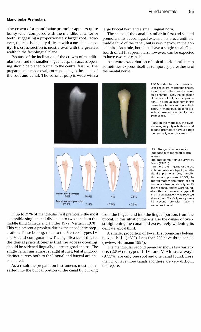
Fundamentals 55
Mandibular Premolars
The crown of a mandibular premolar appears quitebulky when compared with the mandibular anteriorteeth, suggesting a proportionately larger root. How-ever, the root is actually delicate with a mesial concav-ity. It's cross-section is mostly oval with the greatestwidth in the faciolingual plane.
Because of the inclination of the crowns of mandib-ular teeth and the smaller lingual cusp, the access open-ing should be placed buccal to the central fissure. Thepreparation is made oval, corresponding to the shape ofthe root and canal. The coronal pulp is wide with a
large buccal horn and a small lingual horn.The shape of the canal is similar in first and second
premolars. Its buccolingual extension is broad until themiddle third of the canal, but is very narrow in the api-cal third. As a rule, both teeth have a single canal. One-fourth of all first premolars, however, can be expectedto have two root canals.
An acute exacerbation of apical periodontitis cansometimes express itself as temporary paresthesia ofthe mental nerve.
126 Mandibular first premolarLeft: The lateral radiograph shows,as in the maxilla, a wide coronalpulp chamber. Only the extensionof the buccal pulp horn is promi-nent. The lingual pulp horn in firstpremolars is, as seen here, indi-stinct. In mandibular second pre-molars, however, it is usually morepronounced.
Right: In the mandible, the over-whelming majority of both first andsecond premolars have a singleroot and only one root canal.
127
Range of variations inroot canals of mandibular pre-molarsThe data come from a survey byPeters (1992 b).
I n the great majority of cases,both premolars are type I (mandib-ular first premolar 70%; mandib-ular second premolar 97.5%). Inapproximately one-fourth of firstpremolars, two canals of types IVand V configurations were found,while the occurrence of types IIand III configurations was reportedat less than 5%. Only rarely doesthe second premolar have asecond root canal.
In up to 25% of mandibular first premolars the most
from the lingual and into the lingual portion, from theaccessible single canal divides into two canals in the
buccal. In this situation there is also the danger of over-middle third (Pineda and Kuttler 1972, Vertucci 1978).
straightening the canal and excessively widening itsThis can present a problem during the endodontic prep-
delicate apical third.aration. These belong, then, to the Vertucci types IV
A smaller proportion of lower first premolars belongand V canal configurations. The significance of this for
to type II/III (<5%). Less than 2% have three canalsthe dental pracititioner is that the access opening
(review: Hulsmann 1994).should be widened lingually to create good access. The
The mandibular second premolar shows few variati-single canal runs almost straight at first, but at midroot
ons (2.5%) of types II, IV, and V Almost alwaysdistinct curves both to the lingual and buccal are en-
(97.5%) are only one root and one canal found. Lesscountered.
than 1 % have three canals and these are very difficultAs a result the preparation instruments must be in-
to prepare.serted into the buccal portion of the canal by curving

56 Anatomy
Maxillary Molars
The access opening should begin in the central fossatoward the lingual where the pulp is large and easy tofind. The opening should be made rectangular, corre-sponding to the floor of the pulp chamber up to themesial marginal ridge. With age, the chamber becomessmaller through deposition of secondary dentin in alldirections, increasing the risk of perforation throughthe furcation. Therefore, diamond stones should beused only in enamel and round burs in dentin. Devel-opmental concavities and discolorations are importantguides to the canals! Up to 75% of upper molars have
endoperiodontal canals (from the pulp chamber to thefurcation) that are very short and, if overlooked, cancause failure. The maxillary second molar is similar tothe first but somewhat smaller with less divergentroots. In about half of these teeth the roots are unitedand may have canals that are C-shaped in cross-sec-tion. Here too, 43% have a second canal in the mesio-buccal root. The distobuccal canal lies farther mesialthan in the maxillary first molar on a perpendicularguide line (Fig. 129 [2]). The third molar offers aconsiderable range of variations.
128
Locating the canals of amaxillary first molarLeft: A first look at the floor of thepulp chamber of a maxillary firstmolar reveals two buccal and onepalatal canal entrances. The canalwas instrumented and the toothwas pain free for a time. (Casecontinued in Fig. 130.)
Right: View after filling of the rootcanal system.
129 Geometric aidsA Line 1 connecting the mesio-
buccal and palatal cusps. Line2, perpendicular to line 1 at apoint one-third the intercanaldistance from the palatal canal,will pass over the distobuccalcanal.
B The distobuccal canal can liesomewhere along line 2.
C A fourth canal lies somewherealong line 3, which deviates ap-proximately 10°.
130 Significance of a fourthcanalAfter some time, the first molar(Fig. 128) again became sensitiveto temperature changes. Thisevolved into a constant pain. Aperiapical lesion was found on themesiobuccal root and was treatedby an apicoectomy. Even then thepain persisted and the tooth wasfinally extracted.
Left and Right: These views of theextracted molar show an additonalcanal in the mesiobuccal root thatwas not found in the initial rootcanal treatment and was not sealedduring the apicoectomy (arrow).

Fundamentals 57
Characteristics of Maxillary First Molars
The maxillary first molar has three roots and fourcanals. Special attention should be called to the mesio-buccal root, 60% of which have two canals accordingto in vitro studies, 95% when viewed under the micro-scope (Kulild and Peters, 1990). In in vivo studies, twocanals were found in only 18-33% (review: Harty1990). The second canal usually begins beyond a com-mon orifice (Fig. 132). The mesial canals (mesiobuccaland mesiolingual) run first toward the mesial, thenbuccally and in the apical third in a distolingual direc-tion.
Because the two canals of the mesiobuccal root liein a buccolingual plane, a 20° distal eccentric angula-tion should be used for the radiograph, which is not thecase for the other posterior teeth. The distobuccal rootusually has one canal in the center of the root. It is theshortest root and it runs first to the distal and curvesmesially in the apical third. The entrance to the canallies more central than distal. The lingual root (type I) isthe longest and has the largest lumen. The apical end isbent buccally so that the file used for the measuringradiograph should be pre-bent.
131
Complexity of themaxillary first molarsLeft: The buccal view shows thefamiliar configuration of two sepa-rate buccal roots, the tips of whichangle distally. Mesially there is alarge curvature distributed uni-formly along the root, while distallyonly the last two millimeters of theroot tip is sharply bent.
Right: In the mesial view the merg-i ng of the mesial and palatal rootscatches the eye (cf. Fig. 132 centerand right).
132 Various forms of themesiobuccal rootIn vitro studies report a secondcanal in the mesiobuccal root ofmaxillary first molars in 55-69% ofcases.
Left: Mesiobuccal and mesiolin-gual canals usually have a singlecommon opening into the pulpchamber.
Center: Commonly, both canalsexit apically through a single canalas a type II configuration.
Right: The variation with two sepa-rate canals and two foramina mustalso be considered.
133 Complexity of themaxillary second molarsLeft: This palatal view shows thefamiliar shape of a single massivel i ngual root. Here, too, the root tipturns distally, betraying a pro-nounced curve in the overallcourse of the canal.
Right: The distal view reveals awide separation of the buccal andl i ngual root. All root tips are turnedbuccal ly.

58 Anatomy
Mandibular Molars
The access opening for a mandibular molar is madefrom the center of the occlusal surface and approxi-mates a trapezoid shape with the wider base at themesial marginal ridge. It avoids the distal third of thecrown. As in maxillary molars, denticles are frequent-ly found, which must be removed before the canals areprepared. Usually one mesial and one distal root arefound, of which the distal is more slender and round.There are often five pulp horns, the lingual being thelongest and most pronounced. The dentin overhangingthe mesial orifice must be removed in order to reducethe danger of zipping.
The mandibular first molar has two roots; the mesialusually has two canals; ending in a common foramen.The mesiobuccal canal is the more difficult because ofits multiple curves. An initial mesial turn is followedby one to the distal in the middle third. The distobuccalcanal is wider and straighter, but may bend mesiallynear the apex. Between the two mesial canals there areoften complex anastomoses (Peters 1992 d). The singledistal canal is normally larger and oval shaped and in60% of cases exits short of the anatomic apex throughthe distal surface of the root (Tamse et al. 1988).
Furthermore, more than one-fourth of all mandibu-lar first molars have two canals in the distal root (Skid-more and Bjorndal 1971). According to Pineda andKuttler (1972), approximately equal numbers of theseare of type II (13%) and type IV (14%).
The mandibular second molar is similar to the first,except that the roots are shorter, the canals morecurved, and the range of variations broader. Very often(58%) the mesial root has either a single canal or twocanals of type II or IV (approximately 21% incidenceof each; Pineda and Kuttler 1972). In the distal rootthere is almost always only one canal, (>94%) rarelytype II(2.1%) or type IV (3.5%; ibid.).
The C-shaped canal is a unique feature. First de-scribed by Cooke and Cox (1979) with an incidence of8%, it is found predominantly in mandibular secondmolars, but may also occur in mandibular first molars,premolars, and maxillary molars (review: Simon1993 a). In the Chineses population, the incidence canbe 33-52%. The diagnosis is difficult. Clinical clues toits presence are constant residual pain, intermittentbleeding from the canal, and confluent lumina. In theradiograph the roots appear rather conical or fused andthe furcation can barely be seen, if at all (Peters1992 d).
134 Canal entrances in amandibular molarLeft: As a rule, the mesial root hastwo canals (87%) and the distalone canal (73%). The mesialcanals are rather round, and in40-45% of cases terminate in acommon foramen (type II). The dis-tal canal is oval, wider than themesial, and usually ends on thedistal surface of the root short ofthe anatomic apex (Peters 1992 d).
Right: Approximately one-fourth ofall mandibular molars have asecond canal in the distal root,equally distributed between type Iand type IV.
135 Mandibular molarsLeft: As a rule, one mesial rootand one distal root are found inboth first and second lower molars.The end of the mesial root fre-quently curves distally as it doeshere, making instrumentation moredifficult. A characteristic of firstmolars that bears mentioning isthe presence of three buccalcusps: mesiobuccal, mediobuccal,and distobuccal.
Right: The radiograph shows the ex-pected form of a wide coronal pulpchamber with its prominent mesialpulp horn. In this projection eachroot appears to have only one canal.

59
Instruments and Materials
From the access preparation through the root canal obturation to the follow-up procedures (e. g.,apicoectomy, post-core), root canal treatment requires a large, varied armamentarium. Whilesome aids have remained virtually unchanged for decades, important developments have occurredin other areas, such as Ni-Ti instruments, thermoplastic gutta-percha filling techniques, andretrograde ultrasonic preparations. In the 1950's, endodontic instruments were standardized. TheAmerican Dental Association's Council on Dental Materials, Instruments, and Equipment(CDMIE, founded 1966) has been in existence for only a little more than 30 years. The governingauthority is the American National Standard Institute (ANSI). Internationally the TC-106 JW6-1Group (Technical Committee, Joint Working Group) under the mandate of the InternationalStandards Organization (ISO) and the Federation Dentaire Internationale (FDI) is concerned withestablishing standards, of which ISO 3630 (^--' ANSI 28.58.63.71) is the best known (Miserendino1994, Orth 1995).
136 ISO standardizationThe dimensions of endodontic in-struments arranged according tothe recommendations of the Inter-national Standard Organization.Color coding permits rapid visuali dentification of the diameter. Afterthe three smallest sizes #6 pink, #8gray, #10 violet, the sequencewh ite-ye I low-red-bl ue-g reen-blacki s repeated three times.
Left: The cutting section is, in ac-cordance with the ISO standard,16 mm long (1 1 ). Three diametersare specified: d1 at the tip, d 2 atthe end of the cutting portion1 6 mm from the tip, and d3 3 mmfrom the tip.

60 Instruments
The Three Basic Instruments...
All instruments for preparing canals come from threebasic forms: K reamer, K file, and Hedstr6m file. Firstmade of carbon steel, since the 1960's they have beenmade from Cr-Ni stainless steel that is less affected byfrequent sterilization. K types are made by twisting asteel wire of square (for smaller sizes) or triangular(#30 and larger) cross-section. The square shape ismore stable and rigid; its smaller chip space (36%)does not allow the removal of much loosened material.The triangular shape is more flexible, has a larger chipspace (60%), but is more susceptible to fracture. The
angle between the long axis of the instrument and thecutting edge (cutting edge angle) is an indication ofhow it works and its effectiveness. With angles lessthan 45°, a rotating-scraping technique works best.This applies to K reamers (with -20° the smallest) andK files (~40°). H files, with their sharp edges milledfrom round steel wire and an angle of approximately60°, are extremely efficient. They are clearly superiorto K files, which are often recommended for a purelyfiling technique, even though they are more effectivewhen rotated (Schafer 1995 a).
137 K reamersLeft: The K reamer is one of thebasic types of endodontic instru-ment. From left: VDW, Kerr, Mail-lefer.
Center: The SEM picture at 25xmagnification shows the number ofcutting edges and the geomtry of areamer (0.5-1.0 turn/mm).
Right: While the triangle is thesymbol for a reamer, the smallestsizes are quadrangular in cross-section with smaller chip spaces(flutes) of 36%. Larger sizes are tri-angular with 60% chip space.
138
K fileLeft: As early as 1915 the KerrManufacturing Corporation obtaineda patent for all instruments laterknown as K-type instruments, e.g.the K file.
Center: Note: the greater numberof cutting edges (1.5-2.5 turn/mm)compared with the K reamer.
Right: K files also have a cross-section that is quadrangular in thefinest sizes and triangular in largersizes. Their symbol, however, is thequadrangle. The cutting edgeangle, at 25°-40° is approximatelytwice as large as that of a reamer.
139 H files (Hedstr6m files)Left: Hedstr6m files, in contrast tothe K types, are milled from a steelrod of round cross-section.
Center: The SEM picture (25xmagnification) clarifies the differentgeometry with the helical cuttingedge.
Right: The cross-section of an Hfile is round with a spiral milledi nto it, permitting a chip space of35%. Its symbol is a circle. Theangle of the cutting edge is60°-65°.

...and Their Modifications
In order to overcome the disadvantages of the original
with Flexofiles and Flexoreamers. Otherwise, the Flex-types, hybrid instruments were developed in attempts
R is a modification of the K type because of its trian-to combine the advantages of the K types with the
gular cross-section, but it is milled out of a round steelaggressive cutting ability of the H types. Higher flexi-
blank like the H file. Unifiles and S files with thebility was achieved by changing the cross-section and
double helix are also made in a similar manner. In someby using special steel (Flexicut). With the introduction
instruments (Canal Master U, Flexogates, Heliapical)of the Flex-R file (Roane et al. 1985) a new era began.
the cutting portion has been made short in order toIt was recognized that the sharp angles at the instru-
minimize distortion.ment's tip were causing some of the preparation mis-
Because until recently the ISO numbers increasedtakes, and so they were beveled in conformance with
linearly, whereas the diameter increased in steps, inter-the non-cutting tin principle. This was also effected
mediate sizes were introduced-
140 Flexible instrumentsLeft: The square cross-section islarger and therefore more rigid thanthe triangular one. Newer instru-ments are therefore triangular, eveni n the smaller sizes (A-C). Therhomboid (D) is also more flexible,but allows only two cutting edges.
Center: The number of edges ofthe Flexofile (B) is substantiallyhigher. In the K-Flex (D), thickersections alternate with thinner be-cause of the rhomboid form.
Right: A = Flexicut (VDW), B =Flexofile (Maillefer), C = Flexorea-mer (Maillefer), D = K-Flex (Kerr).
141
Non-cutting tipThe Flex-R file by Roane (1985) isthe first to utilize a noncutting tipthat helps avoid ledge formation incurved canals.
Left: The principle of the Flex-R isbased upon removal of the sharpcorners at the instrument tip (dualconical form).
Center: The SEM reveals the geo-metry of the tip (200x magnification).
Right: The intermediate sizes(# 12-37) of the Maillefer GoldenMediums are also made withnoncutting tips.
142 Further modificationsSome manufacturers have greatlyreduced the length of the cuttingportion of their instruments, leav-i ng a longer shaft of round steel.
Left: The simple helicoidal cross-section of the Hedstrom file is mo-dified to a double helix in the S fileand a triple helix in the Helifile( Micro-Mega).
Center: Flexogates (Maillefer) witha 2-mm-long cutting portion.
Right: Heliapical (Micro-Mega)with a 5-mm-long cutting portion.
The Three Basic Instruments...
61
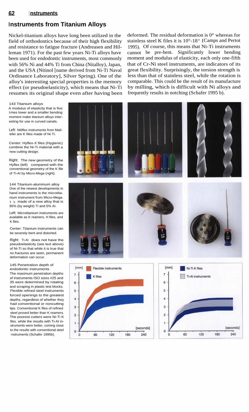
62 I nstruments
Instruments from Titanium Alloys
Nickel-titanium alloys have long been utilized in the
deformed. The residual deformation is 0° whereas forfield of orthodontics because of their high flexibility
stainless steel K files it is 10°-18 ° (Camps and Pertotand resistance to fatigue fracture (Andreasen and Hil-
1995). Of course, this means that Ni-Ti instrumentsleman 1971). For the past few years Ni-Ti alloys have
cannot
be
pre-bent.
Significantly
lower
bendingbeen used for endodontic instruments, most commonly
moment and modulus of elasticity, each only one-fifthwith 56% Ni and 44% Ti from China (Nitalloy), Japan,
that of Cr-Ni steel instruments, are indicators of itsand the USA (Nitinol [name derived from Ni-Ti Naval
great flexibility. Surprisingly, the torsion strength isOrdinance Laboratory], Silver Spring). One of the
less than that of stainless steel, while the rotation isalloy's interesting special properties is the memory
comparable. This could be the result of its manufactureeffect (or pseudoelasticity), which means that Ni-Ti by milling, which is difficult with Ni alloys andresumes its original shape even after having been
frequently results in notching (Schafer 1995 b).
143 Titanium alloysA modulus of elasticity that is fivetimes lower and a smaller bendingmoment make titanium alloys inter-esting for use in curved canals.
Left: Nitiflex instruments from Mail-lefer are K files made of Ni-Ti.
Center: Hyflex-X files (Hygienic)combine the Ni-Ti material with anew cutting design.
Right: The new geometry of theHyflex (left) compared with theconventional geometry of the K fileof Ti-AI by Micro-Mega (right).
144 Titanium-aluminum alloyOne of the newest developments inhand instruments is the microtita-nium instrument from Micro-Mega.It i s made of a new alloy that is95% (by weight) Ti and 5% AI.
Left: Microtitanium instruments areavailable as K reamers, H files, andK files.
Center: Titanium instruments canbe severely bent and distorted.
Right: Ti-AI does not have thepseudoelasticity (see text above)of Ni-Ti so that while it is true thatno fractures are seen, permanentdeformation can occur.
145 Penetration depth ofendodontic instrumentsThe maximum penetration depthsof instruments ISO sizes #25 and35 were determined by rotatingand scraping in plastic test blocks.Flexible refined steel instrumentsforced openings to the greatestdepths, regardless of whether theyhad conventional or noncuttingtips. Conventional K files of refinedsteel proved better than K reamers.The poorest cutters were Ni-Ti Kfiles, while the results with Ti-AI in-struments were better, coming closeto the results with conventional steeli nstruments (Schafer 1995b).
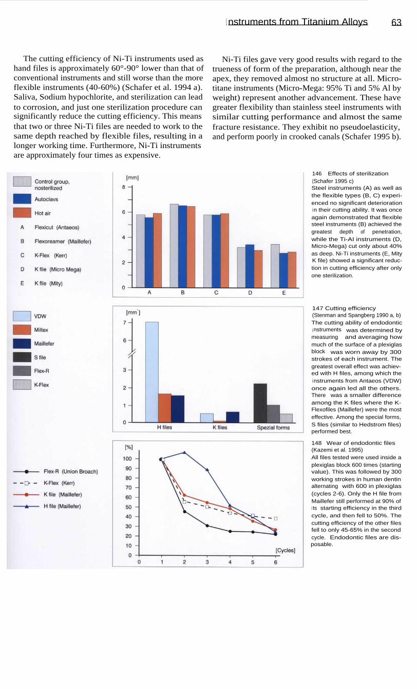
146
Effects of sterilization(Schafer 1995 c)Steel instruments (A) as well asthe flexible types (B, C) experi-enced no significant deteriorationi n their cutting ability. It was onceagain demonstrated that flexiblesteel instruments (B) achieved thegreatest depth of penetration,while the Ti-AI instruments (D,Micro-Mega) cut only about 40%as deep. Ni-Ti instruments (E, MityK file) showed a significant reduc-tion in cutting efficiency after onlyone sterilization.
147 Cutting efficiency(Stenman and Spangberg 1990 a, b)The cutting ability of endodontici nstruments was determined bymeasuring and averaging howmuch of the surface of a plexiglasblock was worn away by 300strokes of each instrument. Thegreatest overall effect was achiev-ed with H files, among which thei nstruments from Antaeos (VDW)once again led all the others.There was a smaller differenceamong the K files where the K-Flexofiles (Maillefer) were the mosteffective. Among the special forms,S files (similar to Hedstrom files)performed best.
148 Wear of endodontic files(Kazemi et al. 1995)All files tested were used inside aplexiglas block 600 times (startingvalue). This was followed by 300working strokes in human dentinalternating with 600 in plexiglas(cycles 2-6). Only the H file fromMaillefer still performed at 90% ofi ts starting efficiency in the thirdcycle, and then fell to 50%. Thecutting efficiency of the other filesfell to only 45-65% in the secondcycle. Endodontic files are dis-posable.
I nstruments from Titanium Alloys
63
The cutting efficiency of Ni-Ti instruments used as
Ni-Ti files gave very good results with regard to thehand files is approximately 60°-90° lower than that of
trueness of form of the preparation, although near theconventional instruments and still worse than the more
apex, they removed almost no structure at all. Micro-flexible instruments (40-60%) (Schafer et al. 1994 a).
titane instruments (Micro-Mega: 95% Ti and 5% Al bySaliva, Sodium hypochlorite, and sterilization can lead
weight) represent another advancement. These haveto corrosion, and just one sterilization procedure can
greater flexibility than stainless steel instruments withsignificantly reduce the cutting efficiency. This means
similar cutting performance and almost the samethat two or three Ni-Ti files are needed to work to the
fracture resistance. They exhibit no pseudoelasticity,same depth reached by flexible files, resulting in a
and perform poorly in crooked canals (Schafer 1995 b).longer working time. Furthermore, Ni-Ti instrumentsare approximately four times as expensive.

64 I nstruments
Engine-Driven Instrumentation
It should be possible to prepare the complex root canal
(Excalibur).systems better and more quickly with engine-driven in-
The Giromatic System, with a recommended enginestruments. Over the past 40 years, a number of mechan-
speed of 3000 rpm for canal preparations, may be con-ical instrumentation techniques using various flexing
sidered the best-known engine-powered system. How-movements have been developed. Some of these em-
ever, its ability to shape the canals is criticized becauseploy reciprocal rotational movements (Giromatic), lift-
of step formation, deviation from the path of the canals,ing movements combined with quarter turn rotations
and overstraightening of curved canals. In 1984, the(Kerr Endolift), pure rotational movement (Endocursor),
Canalfinder System marked the transition to moreor pure lifting movements (Intra-Endo). Others use a
flexible drive systems with longitudinal movementscraping action on the pull strokes (Endoplaner) or
occurring at 1000 to 8000 rpm. However, it also pro-oscillations that vary with conditions inside the canal
duced canal straightening (Hulsmann 1993a).
149 Engine-driven preparationThe primary direction of movementwith the Canalfinder is longitudinali n a low-frequency range with avariable amplitude. If the rotationalspeed increases, the amplitudebecomes smaller, measuring0.3 mm at a speed of 2000 rpm.
Right: A selection of handpiecesfor mechanical preparation: Endo-l i ft (Kerr), Giromatic (Micro-Mega),and Canalfinder in titanium (SETSiemens).
150 Instruments for poweredhandpiecesSome of the instruments availablefor engine-powered preparationand filling of root canals.
Left: Spiral paste fillers (Lentulo) insizes 20 and 30, plugger;
Center: K files and Hedstrom files( Girofiles, Helifile);
Right: Hedstrom files in variousl engths.
151 Engine-driven instrumentsLeft: Giromatic instruments: RispiFile, Giro-File, and Heli-File.
Right: I n the SEM the Cleanser isshown on the left, the Giro-File(Hedstrom file) in the center, andthe Heli Giro-File (K file) on theright.

Engine-Driven Instrumentation
65
A major advance in engine-driven preparation tech-
The Quantec Series 2000 uses Ni-Ti instruments ofniques occurred with the introduction of Ni-Ti instru-
graduating tapers that range from the conventional 0.02ments. Ni-Ti instruments of the Profile Series 29 (Tulsa)
to a 0.06 taper. New design configurations include ahave either a 0.04 or a 0.06 taper and are characterized
more ideal cutting angle of the blades, flutes and wideby an increase in the cross-section of 29.2%. The rota-
radial lands, asymmetry of the cutting surfaces, and ational speed is 250 to 350 rpm. The GT File series con-
faceted cutting edge (Korzen 1996).sists of taper sizes 0.06, 0.08, 0.10, and 0.12. The stan-
Lightspeed instruments (Wildey and Senia 1993)dard file set consists of only four instruments, each
operate with an engine speed of 750 to 2000 rpm. Thewith the same tip diameter. This is a great departure
instrument set contains 22 sizes. The end of eachfrom ISO-tapered files, which come in 21 different tip
instrument has a noncutting pilot tip and a cuttingsizes (Buchanan 1998).
portion, and the shaft is thinner than the cutting head.
152 Profile instrumentsLeft: The Profile .04 is an instru-ment with a U-shaped cross-sec-tion and a taper of 0.04.
Right: The GT files come in fourdifferent tapers (0.06, 0.08, 0.10,and 0.12) and three differentlengths (21, 25, and 31 mm). Allfour files have the same tip dia-meter (0.02 mm), the same 1-mmmaximum flute diameter, and thesame variable-pitch flute pattern.
153 Quantec instrumentsThe Quantec instruments aremade of Ni-Ti and have graduatingtapers ranging from the conven-tional 0.02 taper to a 0.06 taper.These instruments are designed tobe used with a rotational speed ofapproximately 340 rpm. The teni nstruments all have a slightly po-sitive cutting angle permitting cut-ting of the dentin without plowingi nto the surface.
154 Lightspeed instrumentsA set of Lightspeed instrumentscontains 22 sizes with additionali ntermediate sizes. The head of thei nstrument consists of a noncuttingpilot tip and the working part inl engths of 0.25 to 1.75 mm, depend-i ng upon the instrument size. Thepilot tip becomes longer as thediameter of the head increases.The shaft is thinner than the cut-ting head and is very flexible.

155 InstrumentsLeft: The Sonic Air 1500 fromMicro-Mega. This sonic instrumentoscillates in the lower range of upto 6000 Hz.
Center: Instruments that oscillatei n the sonic range: Shaper, Rispi-sonic, Helisonic (Micro-Mega,beginning at the left) and the ultra-sonic Endosonore file (Dentsply-Maillefer, far right).
Right: The Shaper and Rispisonichave a new design with barbsspiraling around the instrument(l eft). On the right are ultrasonicfiles of the K-file design.
156 HandpiecesLeft: Handpiece for sonic instru-mentation: Mecasonic 1400 (Micro-Mega, left). Ultrasonic handpieces:Piezon Master 400 (System 401,EMS), Suprasson (Satelec), and themagnetorestrictive system of CaviEndo (De Trey).
Center: The K-file for ultrasonicuse exposes dentinal tubules. Thewall is clear.
Right: The diamond coated filecaused intensive roughness.
157 Piezo Ultrasonic SystemThe Piezo Ultrasonic System fromSpartan can be used for both or-thograde and retrograde endodon-tic instrumentation. CPR advancedendodontic instruments with a zir-conium nitride coating (left) weredesigned with a contra-angle bendand are scaled to improve opera-tive access in both anterior andposterior teeth. These tips can beused to eliminate pulp stones,break down dental restorationsand cores, dislodge posts and bro-ken instruments, and remove obtu-ration materials from canals.
66 Instruments
Sonic and Ultrasonic Systems
The first ultrasonic system goes back to Richman
the canal. Therefore, small instruments are more effec-(1957). A breakthrough was made 20 years later when
tive and sonic files have the advantage in that theyMartin and Cunningham (1976-1984) provided instru-
vibrate longitudinally under load and the tip of thements that were set into vibration at frequencies of instrument has a greater amplitude than ultrasonic25 000 to 40 000 Hz by magnetostriction or the piezo-
instruments.electric effect. Shortly thereafter, sonic vibration sys-
Furthermore, fractures and problems such as steptems were presented that were powered at frequencies
formation
and
compaction of filings
occur lessof 1500 to 5000 Hz by the air pressure from the dental
frequently with a sonic system because of the lowerunit. All systems produce a transverse vibration in the
frequency. The shaping of the canal as a whole andinstrument being used, but the motion is dampened if
preparation of the apical third are not optimal, so thatthe instrument is pressed against the wall or binds in
often it is used in combination with hand instruments.

Sonic and Ultrasonic Systems
67
For a long time, the cavitation effect was considered
combination of ultrasound and sodium hypochlorite isto be the essential mechanism in ultrasonic cleaning.
superior. Unfortunately, the actual preparation is againMeanwhile, it was recognized that only microacoustic
plagued by the problems of roughness, alterations ofcurrents with small primary vortices in the region of
shape, and blockages in the canal, so that hand instru-the oscillation crest and large secondary, or outer, vor-
ments cannot be dispensed with, even with ultrasound.tices produce shearing forces that tear apart tissue rem-
The field of application of ultrasound in endodontics isnants, bacteria, and blood cells. Since this effect only
now being widened by its use in micropreparationsoccurs in liquids, however, Martin and Cunningham
during apicoectomies. The fineness of the instruments(1984) coined the term "endosonic ultrasonic synergis-
and their quick, efficient cleansing action make it postic system." Therefore the use of an irrigating solution
sible to prepare excellent retrograde cavities.i s a basic prerequisite. Cleaning and disinfection with a
158 Ultrasonic apparatusThe Suprasson P-Max (Satelec) isset up as a multiclinic generator(MCG). Four different intensities(weak, medium, strong, and pow-der jet) are available from one ul-trasonic generator. In this way awide selection of dental applicati-ons, such as endodontics, retro-surgery, microretrosurgery, andgutta-percha condensation (not tomention calculus removal, peri-odontal therapy, crown and bridgeremoval, crown preparation, andcementation of inlays) are madeavailable by changing the hand-piece insert.
159 Retrosurgery withultrasoundLeft: The endodontia handpiecesfrom Satelec and EMS are quicklyadapted for use in retrogradepreparation of the root canalfollowing root resection by screw-i ng on specially formed microcut-ting tips.
Right: The no. 15 inserts are lon-ger and thinner and thereby de-signed for microretrosurgery. Again,they are paired, one for the upperright and lower left teeth and onefor the opposite sides. They arealso diamond coated (D).
160 RetrosurgeryThe diamond-coated tips shouldspeed up the canal preparationsand shorten the time required forthe entire operation.
Left: Diamond-coated tips withangles of 120° and 90° (S 12/90 Dand S 12/120 D from Satelec) areuniversally applicable for retrosur-gery.
Right: The S 13 LID retrotip inserton the left was designed for theupper left and lower right teeth. Itsmate on the right, the S 23 RD, isfor the upper right and lower left.

161 Apicoectomy handpiecesA direct size comparison showsthe great difference between thenew and the conventional instru-ments for apicoectomies and retro-grade canal preparation: ultrasonichandpiece with retrotips (EMS,left), surgical handpiece with car-bide steel drill (Impact Air 45,USA), and contra angle handpiecewith diamond stone (KaVo).
Right: Tips for retrograde prepara-tions CT 1-5 (universal, right, left,i nstrument removal, and isthmus)to be used with EMS, Enac, andspartan, satelec ultrasonic units.
162 Special instruments formicroapicoectomyOnly a few manufacturers offer acomplete microinstrumentarium forapicoectomies (shown here, Dep-peler, CH). Some of the instru-ments included are a microex-plorer (VA 7), spatula (VA 9, 10),plugger (VA 9-14), spoon (VA 16),and carver (VA 20) designed by Dr.Velvart.
Upper right: Microsurgical scal-pels CK1-5 (EIE: Excellence inEndodontics, USA).
Lower right: The micromirrors(Sapphire Plus Retro Mirrors, EIE)with a size 4 regular mouth mirrorfor size comparison.
68 I nstruments
Microsurgical Endodontics
Formerly, retrograde treatment of the root canal was
with the commonly used standard handpieces, areperformed when, for example, the conservative end-
avoided. Following the removal of 3 mm of the rootodontic treatment was not successful or the apical lesion
tip, a retrograde cavity is prepared another 3 mm intowas very large. In contrast to conventional procedures,
the root using special ultrasonic retrotips. These area sulcular entrance incision is made with a micro- very fine and suitably angled for optimum access.scalpel in microsurgery. A flap is then prepared and the
However, the miniaturization will not be fully complet-root tip is exposed. The tip is removed using a micro-
ed until improved visual microscopic monitoring of thehandpiece (e. g., Impact Air 45, EIE), the head of
preparation is available. The microset is rounded outwhich is already fixed at the 45° resection angle.
by precisely designed instruments for preparation andFurthermore, no air is exhausted at the working end of
filling, as well as a micromirror.the handpiece so that air emboli, which have occurred
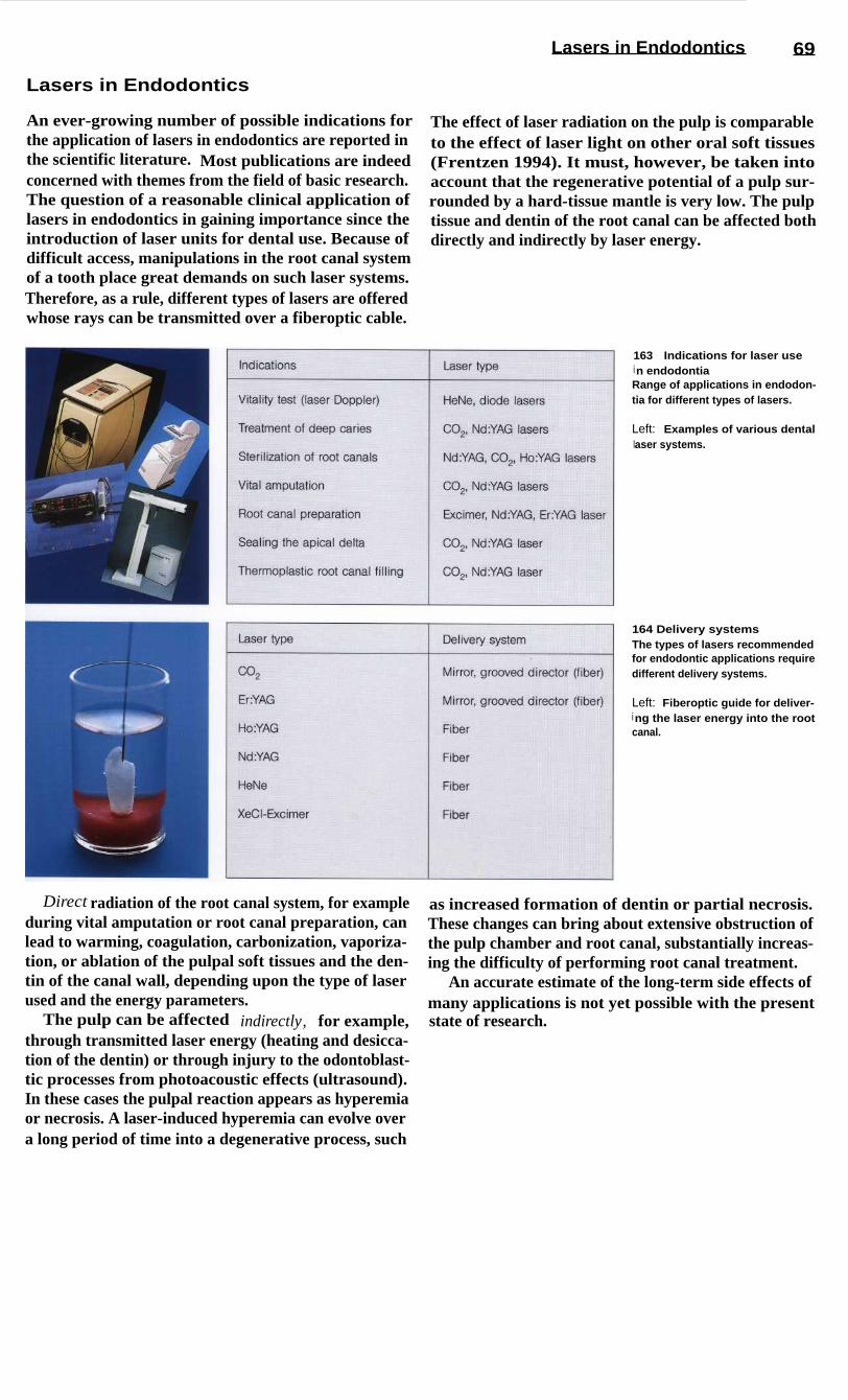
Lasers in Endodontics
69
Lasers in Endodontics
An ever-growing number of possible indications for
The effect of laser radiation on the pulp is comparablethe application of lasers in endodontics are reported in
to the effect of laser light on other oral soft tissuesthe scientific literature. Most publications are indeed
(Frentzen 1994). It must, however, be taken intoconcerned with themes from the field of basic research.
account that the regenerative potential of a pulp sur-The question of a reasonable clinical application of
rounded by a hard-tissue mantle is very low. The pulplasers in endodontics in gaining importance since the
tissue and dentin of the root canal can be affected bothintroduction of laser units for dental use. Because of
directly and indirectly by laser energy.difficult access, manipulations in the root canal systemof a tooth place great demands on such laser systems.Therefore, as a rule, different types of lasers are offeredwhose rays can be transmitted over a fiberoptic cable.
163
Indications for laser usei n endodontiaRange of applications in endodon-tia for different types of lasers.
Left: Examples of various dentallaser systems.
164 Delivery systemsThe types of lasers recommendedfor endodontic applications requiredifferent delivery systems.
Left: Fiberoptic guide for deliver-i ng the laser energy into the rootcanal.
Direct radiation of the root canal system, for example
as increased formation of dentin or partial necrosis.during vital amputation or root canal preparation, can
These changes can bring about extensive obstruction oflead to warming, coagulation, carbonization, vaporiza-
the pulp chamber and root canal, substantially increas-tion, or ablation of the pulpal soft tissues and the den-
ing the difficulty of performing root canal treatment.tin of the canal wall, depending upon the type of laser
An accurate estimate of the long-term side effects ofused and the energy parameters.
many applications is not yet possible with the presentThe pulp can be affected indirectly, for example,
state of research.through transmitted laser energy (heating and desicca-tion of the dentin) or through injury to the odontoblast-tic processes from photoacoustic effects (ultrasound).In these cases the pulpal reaction appears as hyperemiaor necrosis. A laser-induced hyperemia can evolve overa long period of time into a degenerative process, such

165
Principle of the laserDoppler flow measurementS SenderE Receiverv o Frequency of the emitted laser
beamv Frequency of the reflected laser
beamv Veloctiy of flow
166
Laser treatment of a"pulp wound"Left: Carbonization of the cavityfloor. A histologic preparationfollowing sealing of a cavity indentin with a C02 l aser.
Right: Schematic of the steriliza-tion and sealing of the cavity sur-face. After preparation and remov-al of the carious structure, altereddentin near the pulp is exposed toa C0 2 l aser beam. The laser-induced "sealing" of the dentin issupposed to stimulate the pulptissue to produce new dentin.
70 Laser
Vitality Test with the Laser Doppler Probe
One measuring procedure that has already proven itself
used in basic research to measure changes in the circu-in dental diagnosis is laser Doppler flowmetry (Ten-
lation of blood in the pulp due to influences such asland 1982). It can, for example, be used to determine
thermal stimuli or local anesthetics (Raab and Mullerthe circulation of blood in the pulp. The principle rests
1989, Raab 1989). It is already possible to use thisupon variations in the signals reflected from moving
procedure as a "true" vitality test of the dental pulperythrocytes when radiated with laser light, the varia-
following trauma. However, this still requires hightions depending upon the direction and speed of move-
technical expense in order to achieve reproducible,ment. HeNe or diode lasers are used for laser Doppler
valid diagnostic data.probes. Because of the greater penetration depth oflaser rays of 750-800 run, diode lasers are preferred forclinical measurement. Laser Doppler flowmetry can be
Laser Treatment of Cut Dentin and the Pulp
Removal of deep caries produces what may be called a
The infrared laser beam induces reactions in the pulpdentin wound. Usually, the possibility that the remain-
lying under the irradiated surface that apparently caning dentin might still be infected with bacteria cannot
lead to hyperemia followed by an increased formationbe excluded. In these cases it has been recommended
of tertiary dentin (Melcer et al. 1985, Yamamoto et al.that the floor of the cavity be irradiated with an infra-
1989). Still open to discussion is whether the thermalred laser beam (Melcer et al. 1984). In vitro studies
stimulation associated with conventional therapeutichave shown that the smear layer can be. fused. The
methods produces any chronic changes in the pulpdentinal tubules can be sealed through denaturation of
evoking chronic pulpitis, which in turn would makethe organic structural elements (Melcer 1982, Tani and
later endodontic treatment of the tooth more difficult.Kawada 1987). The biologic effect of the denatureddentin products had not previously been investigated.

Lasers in Endodontics
71
Vital Amputation
Vital amputation of the pulp of a deciduous toothsometimes becomes necessary during caries removal inorder to preserve the tooth as a space maintainer. Pulpamputation may also be indicated when there is incom-plete root growth to bring about apexification. As analternative to conventional procedures that utilize pulpamputation pastes, the vaporization or superficialcoagulation of the pulp stump with C02 and Nd: YAGlasers has been proposed. In vitro studies and experi-ments on animals have shown that this can producegood hemostasis.
The zone of coagulation following irradiation with aCO2 laser is approximately 100 pm deep, with appro-priate selection of the parameters (Shoji et al. 1985).The thermal load on the surrounding tissue is small(Arrastia et al. 1994). The tissue surface at the amputa-tion site suffers minimal trauma. Formation of a denti-nal bridge has been observed in the region of the am-putation following the application of both CO 2 lasersand Nd: YAG lasers (Kato et al. 1991, Mungo andRichardson 1993). Clinical studies on the efficacy oflaser amputation are not yet available, however.
167 Root apex after attemptedlaser sealing with an Nd: YAGlaserLeft: Pulp tissue and superficialcanal dentin were carbonized, for-mation of cracks into deeper den-tin layers (1.75 W; sectioned tooth).
Right: Enlarged section.
168 Root canal preparationwith Nd: YAG laser (1.75 W;sectioned tooth)Left: Carbonization of the dentinsurface. The effect of the laserbeam is dependent upon the sur-face structure of the canal wall. Auniform result was not achieved.
Right: Fractured delivery fiberfrom an attempt to prepare the rootcanal with an XeCl* laser. The fiberfragment (arrow) could not be re-moved (nondemineralized thinsection at 30x magnification).
Sealing the Root Canal
Fundamental studies are primarily concerned with thequestion of whether the walls of the root canal can besealed and sterilized through laser irradiation (Dede-rich et al. 1984). The ability of dyes to diffuse throughthe dentinal surface is reduced by treatment with an in-frared laser (Tani and Kuwada 1987). The main reasonfor this is the laser-induced fusion of the smear layer.The surface of the root canal is covered by a glass-likelayer of melted dentin, interrupted by hairline cracks.Attempts have been made to seal the apex by meltingthe dentin near the apex into a glass-like mass with
higher energy levels (Weichmann and Johnson 1971).However, the high thermal load from the infrared ra-diation leads to a loss of continuity between the variouslayers of dentin and cementum, and so this method isnot applicable in clinical use at the present time. An in-teresting variation is the melting of dentin chips into amore or less homogenous mass in the periapical region(Zakariasen et al. 1985).

72 Laser
Root Canal Preparation
A few studies have been directed at the possibility oflaser preparation of root canals (Levy 1992, Liesenhoffet al. 1989). Attempts to perform root canal prepara-tions with an Nd: YAG laser, however, have producedsubstantial changes in the canal wall (Fig. 168, left).With the XeCl* laser, an ablation of pulp tissue anddentin, primarily through its side effects, is possible;the ability to remove material is poor, however. In vitrostudies have shown that the ablation threshold couldnot yet be reached (Fig. 169). Furthermore, the effectof pressure from the expansion of plasma in the root
canal cannot be ignored, as it could damage the peri-apical tissues.
Because of their low level of effectiveness, it isdoubtful whether these procedures will have any clini-cal usefulness (Frentzen et al. 1991). One special prob-lem in the use of fiberoptic conductors in endodonticsis the danger of fibers breaking; the fiber fragmentscannot usually be removed (Fig. 168, right).
169 Histologic investigationsfollowing root canal preparationMechanical systems are superiorto laser applications; in all casesthe histologic result was improvedby the use of sodium hypochloritesolution.
170 "Burnt-off" fiber endsThe light-conducting fibers fre-quently develop signs of wear inthe form of melting and chippingaway of the ends. The biologiceffect of this burn-off has not yetbeen clarified.
Left: Fiber bundle.
Right: Fiber tip.
Root Canal Desinfection
It is usually not possible to achieve a thoroughly cleanpreparation of a curved root canal with hand instru-ments or an engine-driven instrument system alone be-cause of the morphology of the canal walls. Therefore,the canal is also flushed with a tissue-dissolving disin-fecting solution to complete the mechanical prepara-tion and create the most aseptic conditions possible forthe canal filling.
The use of lasers has been suggested to complementthese methods. Comparative studies verify that anti-microbial effects comparable to those of conventional
methods (e.g. irrigation with NaOCI) can be achieved(Hardee et al. 1990). At this time, the problem in dis-infecting root canals with laser beams lies in guidingthe beam within the canal. Most of the energy from alight-conducting fiber is emitted in the axial directionand not toward the canal wall. Because of this, laser-in-duced necrosis in the periapical region has been de-monstrated following attempts to "sterilize" the rootcanal, especially with the Nd:YAG laser beam (Bahcallet al. 1992).

I rrigating, Drying, and Medicated Dressings
Irrigating, Drying, and Medicated Dressings
73
As an irrigating solution, sodium hypochlorite is usedalmost exclusively today. A 1 % solution has the uniqueability to selectively dissolve necrotic tissue withoutinjuring the vital pulp tissue. Its disinfecting andbleaching effects are additional advantages. It isimportant to flush the canal frequently (after everychange to the next size of instrument) with a largequantity (5 ml) of solution. It is necessary to carefullydry the canal before the introduction of each and everymaterial.
If treatment cannot be completed at an appointmentbecause of time constraints or medical reasons (exuda-tion, bleeding, fetid odor, etc.) a medicated dressingmust be applied. Strong disinfectants or antibiotic-con-taining substances have been promoted for a long time,but today we know that every endodontic-related le-sion will heal if the canal is carefully prepared, cleans-ed, and then tightly sealed (Ehrmann 1987). The onlydressing needed, therefore, is a thin suspension of cal-cium hydroxide, which has very good biocompatibili-ty, stimulates osteoblastic activity, and is a disinfectant.
171
Paper points for dryingcanalsThe chemical-mechanical prepara-tion must be followed by thoroughdrying. For this purpose, paperpoints in ISO sizes # 15-140 areavailable. In addition to the con-ventional white points, paperpoints are becoming increasinglyavailable in colors correspondingto the ISO coding (center).
Left: Close-up photograph ofcolor-coded paper points # 15-40.
Right: Sealed packets containingsmall numbers of sterilized paperpoints, both white and colored, arealso available.
172 Interim dressingA thin aqueous suspension of cal-cium hydroxide can be used as amedicated dressing. The mostfamiliar brand is Calxyl (OCO-Praparate). The addition of barium(Calxyl Blue) provides good visibil-ity in radiographs. Calxyl Red isbarium-free. The suspension canalso be used for irrigation.
Left: Calxyl is also offered in asyringe system to facilitate appli-cation into the canal. It is importantthat the cap is airtight whenreplaced because otherwise thesuspension will quickly dry out.
173 Application system(paste fillers)Full spirals have long been used toplace final pastes and cements.Today, because of their high risk offracture, they should only be usedfor inserting provisional dressings.
Left: The #4 full spiral (Maillefer,black) is i ndicated for sizes# 70-90 canals. Attached to theshank of the VDW instrument(right) there is a safety spiral toreduce the danger of fracture.
Right: The gutta-percha condens-er (Maillefer) is especially suitedfor inserting Calxyl.

74 Gutta-percha
Gutta-percha
The term "getah pertja" is Malay and means "threadsfrom sticky plant sap." The gutta-percha tree producesthe raw substance (a gray, translucent mass with a pinksheen) for dental material. Chemically, it is the trans-form of polyisoprene, that is harder, more brittle, andless elastic than the more familiar natural rubber.Through the addition of wax and resins as softeners(1-4%), metal sulfate for radiopacity (1-15%), andzinc oxide filler as the main component (59-76%), thefamiliar consistency of the gutta-percha point is reach-ed (Weine 1994). Gutta-percha exists in different mod-
ified forms:- a form 42-49 °C- B form (room temperature; 53-59 °C)- ,y form (56-62 °C).
The gutta-percha used in dental practice is usually inthe form. The warm gutta-percha technique (e. g.,Obtura, Ultrafil, Thermafil) was the first to utilize thea form. At high temperatures, gutta-percha behaveslike a thermoplastic synthetic resin: softening above65 °C, melting at 100 °C and, in the a form, fluid with-out decomposition above 160 °C.
174 Gutta-perchaThe sap of the isonandra gutta treeis the raw material for gutta-per-cha. Chemically, it is the polymerof the trans-form of the isoprenemolecule. Normally, gutta-perchaoccurs in the 0-form (dental gutta-percha points at room tempera-ture). When it is heated to soft-ening (65 °C) and cooled slowly(0.5 °C/h), at 42-49 0C the (x-formappears, which is sticky, fluid, andtoo soft to be condensed.
Right: Standardized gutta-perchapoints in ISO sizes # 15-40.
175 Standardization of gutta-perchaGutta-percha points often exhibitsuperficial irregularities (SEM at130x magnification).
Upper right: The dimensions of agutta-percha point are specified inseveral measurements. The stan-dards identify three points (d1 atthe tip, d3 , and d 16), and also de-scribe nonstandard points. On thel eft a standardized gutta-perchapoint is represented and on theright, one that is nonstandard ized.
Lower right: A gauge (Maillefer) isi ndispensable for determining thetrue diameter, because gutta-per-cha points can have a tolerance of± 0.04 mm.
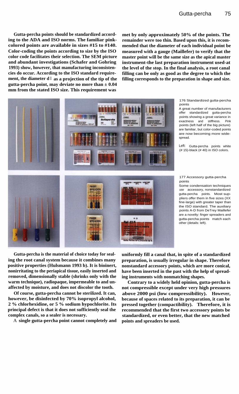
Gutta-percha 75
Gutta-percha points should be standardized accord-ing to the ADA and ISO norms. The familiar pink-colored points are available in sizes #15 to #140.Color-coding the points according to size by the ISOcolor code facilitates their selection. The SEM pictureand abundant investigations (Schafer and Gohring1993) show, however, that manufacturing inconsisten-cies do occur. According to the ISO standard require-ment, the diameter d l as a projection of the tip of thegutta-percha point, may deviate no more than ± 0.04mm from the stated ISO size. This requirement was
met by only approximately 50% of the points. Theremainder were too thin. Based upon this, it is recom-mended that the diameter of each individual point bemeasured with a gauge (Maillefer) to verify that themaster point will be the same size as the apical masterinstrument-the last preparation instrument used-atthe level of the stop. In the final analysis, a root canalfilling can be only as good as the degree to which thefilling corresponds to the preparation in shape and size.
176 Standardized gutta-perchapointsA great number of manufacturersoffer standardized gutta-perchapoints showing a great variance inexactness and stiffness. Pinkpoints (left half of the big picture)are familiar, but color-coded pointsare now becoming more wide-spread.
Left: Gutta-percha points white(# 15)-black (# 40) in ISO colors.
177 Accessory gutta-perchapointsSome condensation techniquesuse accessory, nonstandardizedgutta-percha points. Most sup-pliers offer them in five sizes (XXfine-large) with greater taper thanthe ISO standard. The auxiliarypoints A-D from DeTrey Mailleferare a novelty: finger spreaders andgutta-percha points match eachother (details: left).
Gutta-percha is the material of choice today for seal-ing the root canal system because it combines manypositive properties (Hulsmann 1993 b). It is bioinert,nonirritating to the periapical tissue, easily inserted andremoved, dimensionally stable (shrinks only with thewarm technique), radiopaque, impermeable to and un-affected by moisture, and does not discolor the tooth.
Of course, gutta-percha cannot be sterilized. It can,however, be disinfected by 70% isopropyl alcohol,2 % chlorhexidine, or 5 % sodium hypochlorite. Itsprincipal defect is that it does not sufficiently seal thecomplex canals, so a sealer is necessary.
A single gutta-percha point cannot completely and
uniformly fill a canal that, in spite of a standardizedpreparation, is usually irregular in shape. Thereforenonstandard accessory points, which are more conical,have been inserted in the past with the help of spread-ing instruments with nonmatching shapes.
Contrary to a widely held opinion, gutta-percha isnot compressible except under very high pressuresabove 2000 psi (low compressibility). However,because of spaces related to its preparation, it can bepressed together (compactibility). Therefore, it isrecommended that the first two accessory points bestandardized, or even better, that the new matchedpoints and spreaders be used.

76 Gutta-percha
Cold and Warm Condensation of Gutta-percha
While the insertion of a single gutta-percha cone is ob-solete, vertical and lateral condensation with hand orfinger instruments is still used today.
The technique of lateral condensation uses a well-fitting master point with friction at the apical reagion.Then a spreader is chosen which is 1 mm short of theworking length. The remaining space is filled with onegutta-percha point after the other, working "step back"1 mm until a dense compaction is reached. Pluggersenable a vertical compaction.
Starting with the "sectional gutta-percha technique"(Coolidge 1946) warm condensation techniques havebeen widespread within the last decade. Vertical con-densation (3D obturation) by Schilder (1967) can beexcellent, but is complex and time-consuming, needingspecial instruments. A variety of other systems areavailable:-Obtura (Yee et al. 1977)-Thermafil (Johnson 1987)-Ultrafil (Michanowicz and Czonstokowsky 1984)-System B, SuccessFil, JS Quick-fill, Trifecta, etc.
178 Hand spreadersHand spreaders in sizes # 30-60for the lateral condensation ofgutta-percha (Hu-Friedy). Manyhand spreaders are calibrated sothat the depth of insertion can bemonitored during condensation.
179 Finger spreadersLeft: Finger spreaders are oftenpreferred because of a finer senseof feel for the direction of thecanal, the resistance met, and theforce being exerted.
180 Hand pluggersThe working end of the hand plug-gers has markings every 5 mm toenable measurement of the pe-netration depth (#30-#60 by Hu-Friedy).
Right: The heat carrier plugger(Dentsply Maillefer) have onespreader-like end and one plug-li ke end with diameters of 0.5, 0.6,0.8, and 1 mm. They can be usedeither for cold or warm condensa-tion (3D technique after Schilder).

77
Rubber Dam
During endodontic treatment, use of a rubber dam to keep the tooth absolutely dry is mandatory.Only in this way can we fulfill the requirement of creating an aseptic field and thereby protectboth the patient and the treatment team from infection. In spite of the numerous additionaladvantages (such as protection from aspirating and swallowing instruments, improved view andaccess to the operating field, saving of time, etc.) there is still widespread skepticism andreluctance among dentists to use the rubber dam. According to one survey, the rubber dam is usedin 60% of endodontic procedures in the United States and Scandinavia, whereas in Germany 5%of the respondents used the rubber dam in all cases and 65% never used it (Winkler 1991). Thereasons for this nonacceptance are many, often repeated, but nonetheless obscure. A quotationfrom Cragg (1972) describes the phenomenon well:
"The most time-consuming thing about the rubber damis the time required to convince the dentist to use it."
Trends have emerged in recent years that are bringingabout increased use of the rubber dam. For one thing,some very good books (e. g., Reid et al. 1991; Winkler1991, with videotape) and articles (e. g., Zeppenfeld1990) have appeared. For another, many continuingeducation courses are being offered on use of the rub-ber dam, and dentists are sure to be motivated by these.
Furthermore, the increasing use of adhesive bondingand luting of ceramic and composite restorations isproviding insight into the necessity and usefulness ofthe rubber dam and, very importantly, future dentistsare becoming more and more familiar with the rubberdam as a routine procedure and will later incorporate itinto their practices.
Much time has passed since the innovative idea oc-curred to the New York dentist S. Bamum, who on 15March, 1864, while treating a lower molar, sponta-neously made a hole in a sheet of rubber and stretchedit over the tooth to keep it dry. Even though rubber damclamps in their present form were developed only laterand rubber dam frames did not yet exist, many of theaspects of rubber dam utilization have been modified
only slightly since then. As early as 1894 one wouldhave found the Ivory clamps that are still used today,the Ainsworth hole-punch (almost unchanged today)and a large number of other highly developed acces-sory items. In the 1920's the New York Academy ofMedicine emphasized the importance of rubber damuse in endodontics, although at that same time the be-ginning of the focal infection theory, the use of silveramalgam, and improved suction techniques led to adecline in its use. Throughout its tumultuous history,the rubber dam's value in endodontics and placementof gold foil restorations was further emphasized in text-books (Winkler 1991).
It is intended that the following pages will giveadded support to this development process, in that thepreferred instruments and materials introduced forutilizing the rubber dam in endodontics and the actualapplication technique are presented in a series of pic-tures. Those with further interest may deepen theirknowledge through the books, reports, and articlesdealing exclusively with the rubber dam that are men-tioned.

78
Rubber Dam
Rubber Dam Material
A sheet of rubber 6 inches square (15 cm x 15 cm) isthe most commonly used rubber dam material. The rawmaterial for this, as well as for latex gloves, is the sapof the caoutchouc tree. This is primarily cis-1,4 poly-isoprene (as opposed to gutta-percha which is thetrans-form). Of the five thicknesses available, themedium, heavy, and extra heavy are preferred in end-odontia. Latex allergies are becoming more and morecommon and this must be taken into account. Conse-quently, a PVC or silicone material must be substitutedif the patient is allergic to latex (Denis and Ott 1993).
During endodontic treatment it is usually necessaryto isolate only one tooth, and therefore a single hole,centrally located or slightly off-center, is often all thatis necessary. For isolation of larger areas, hole patternsor stamps can be used to orient the holes. The Ivoryrubber dam punch is recommended for making theholes. Shaving soap, Vaseline, or special lubricantsmake it easier to slide the rubber dam over the teeth.The patient's comfort is greatly increased by spreadinglotion on the lips and by applying a paper napkin thatis either commercially prepared or cut at chairside.
181 ArmamentariumLatex rubber sheets come in var-i ous thicknesses and colors. Thesize is 5 in x 5 in (12.5 cm x 12.5cm) (green) or 6 in x 6 in (blue,cream). The napkin prevents therubber from resting directly againstthe skin. A silicone rubber (brightgreen) has recently become avail-able for patients allergic to latex.
Lubricants
(e. g.,
Dentaglide,Sigma Dental, or Vaseline) make iteasier to pull the rubber dam overthe teeth. The spacing of the holesi s facilitated by using a template ora stamp.
182
Latex allergyRedness appeared around themouth of this patient shortly afterplacement of a latex rubber dam.Vesiculopapular changes in theskin and itching also occurred.This is an immediate allergic reac-tion (type I according to Coombsand Gell).
Latex allergies are known to rap-idly grow worse, and the conditioncan progress to a life-threateningstate of shock. Therefore, the den-tist must uncover any history ofsuch reactions beforehand and beable to correctly comprehend thesituation.
183 Rubber dam punchesThe Ivory rubber dam punch is thebest instrument for perforating therubber sheet (left). It is constructedso that it can reach quite far to-ward the center of the dam. Theplacement of the hinge ahead ofthe hole plate permits a precise,almost vertical, punching motion.
The Ainsworth punch (right) hasremained unchanged for approxi-mately 100 years.
Right: This close-up view of theI vory punch shows the hole platewith six openings ranging in sizefrom 1-2 mm.

Rubber Dam Clamps
79
Rubber Dam Clamps
In the early days of rubber dam usage, the rubber sheetwas held in place by wooden wedges or dental floss.Soon, many different forms of clamps appeared thatwere designed to fit the individual teeth and irregularareas. Today, steel clamps are the most prevalent,although there are a few available that are made ofsynthetic resin.
The clamp should make only point contacts with thetooth. In addition to retention, which is achievedthrough spring action and the engagement of under-cuts, retraction of the gingiva is also desirable.
Rubber dam clamps can be divided into the follow-ing types:-normal clamps (with wings, Fig. 185)-wingless clamps (wingless = W)-distal clamps (distal = D)
,-anterior tooth, premolar, and molar clamps-cervical or labial clamps-retention clamps (to hold the rubber sheet)
retraction clamps (to press down the gingiva; e. g.,Brinker tissue retractors, Schultz clamps).
185 Clamp selectionBecause three are so many differ-ent shapes of rubber dam clampsand so many manufacturers, thechoice is not easy. Therefore, aclasp set can serve as a goodorientation aid. The selectionshown here is from the Ivory com-pany and contains eight types:
8A
Molar with broken-down crown14A Molar, partially erupted8
Maxillary molar7
Mandibular molar212 Anterior teeth0
Premolar (high bow)1
Premolar, general2
Mandibular premolar
186
I ndividual types of claspsLeft: The #212 clasp for anteriorteeth (and some premolars). Thetwo bows hold the rubber dam outof the way on both sides, or can beused to atttach Kerr compound tothe dental arch.
Center: Molar clamps. The jaws ofthe #7 lie in a flat plane. The in-wardly curved jaws of the #8Ahelp secure the clamp on a badlydamaged tooth.
Right: Two wingless clamps: Hy-genic B 2 (mandibular molar left)and Hygenic B 3 (maxillary molarright).
184 Rubber dam clamp
1 Clasp arm(lingual and buccal) with:1.1 central wing1.2 anterior wing
2 Bow (distal)3 Jaws4 Contact point5 Notch6 Perforation

80
Rubber Dam
Additional Preparations
Once the rubber dam material and clamp have been se-lected, the rubber dam forceps is used to grasp andspread the clamp. The Ivory model is preferred becauseinjury to the gingival tissues is more easily avoided.
Rubber dam frames are available in a wide array ofmodels. Some authors prefer plastic frames becausethey will not show up on radiographs and therefore thedam need not necessarily be removed for radiographs.On the other hand, plastic frames undergo deteriorationduring autoclaving so that they become unsightly andthe pegs break off. Metal frames should be provided
with plastic caps on the ends to protect the patient'sskin and eyes from injury. To facilitate and speed upthe procedure, the assistant should routinely prepare acomplete rubber dam tray in advance. Wedjets, dentalfloss, and either composite, cement, or impressioncompound (e. g. Kerr) should be within reach to useas retentive aids. Cavit or periodontal dressing canbe used for sealing the rubber dam after it is in thepatient's mouth.
187 Clamp forcepsThe Ivory clamp forceps is pre-ferred. A steel spring behind thehinge combined with a slidingsteel strap can hold the forceps atany desired degree of opening.The working arms are bent at twoangles, facilitating introduction intothe mouth.
Right: The Ivory forceps has reten-tion pegs that join the arms at awide surface, which helps preventthe pegs from projecting throughthe clamp's perforations and injur-i ng the gingiva.
188 Rubber dam framesMany of the frames for stretchingthe rubber dam are U-shaped sothat the lower bar lies against thechin and the open part is near thenose. Among these are plasticframes (upper left) and radiopaquemetal frames such as the 5 in (12.5cm) and 6 in (15 cm) sizes fromYoung, shown on the lower right. Anew development is the foldingframe by Sauveur (lower left) thathas hinges so that one side can befolded away from the mouth for theplacement of an X-ray film.
189 Complete rubber dam trayAdvance preparation of a rubberdam tray by the assistant facilitatesand speeds up the placement of arubber dam. A prepunched rubbersheet, frame, clamp forceps,clamp, and hemostat lie ready foruse.
Right: Some examples of addition-al aids for securing the rubberdam are Wedjets (rubber bands indifferent thicknesses from a dis-penser), dental floss, woodenwedges, and Kerr impression com-pound.

Placing the Rubber Dam
81
Placing the Rubber Dam
There are many methods for applying the rubber dam.In the following text, four commonly used techniqueswill be described. In general, it is a good idea to keepthe following considerations in mind:-If the clamp is attached to the rubber before it is
carried to the mouth, ligation with dental floss toprevent the clamp from being swallowed is notnecessary.
-Having the rubber already stretched over the framemakes it easier to mount it symmetrically and re-duces the time it takes to apply it in the mouth.
Rubber Dam Application I (Bow Technique)
The bow technique can be employed without an assis-tant if the steps outlined here are followed. An additio-nal advantage is that it provides a good view into themouth as the clamp is being placed on the tooth. Adisadvantage is that the rubber must be stretched overthe wings and this can cause it to tear. To avoid this, thelargest punch should be used for making the hole. Theframe cannot be applied until last.
190 The bow techniqueLeft: First, the retaining pegs of theforceps are placed through theperforations in the clamp. Then thei ndex finger is used to press thedam against the forceps at thel evel of the hinge. The dam isstretched with the other hand andpulled over the bow of the clamp.
Right: The opening in the rubbersheet is pulled completely over thebow of the clamp, and the rubberi s gathered together for betterhandling.
191
I nsertion phase ILeft: The rubber-clamp-forceps as-sembly is placed against the pa-tient's mouth.
Center: The clamp is attached tothe tooth. With this technique theview is unobstructed and thei nvolved tooth can be easily found.
Right: The dam material is pulledbuccally over the central wing ofthe clamp.
192
I nsertion phase IILeft: The buccal wing is complete-l y exposed.
Right: The rubber dam lies in itsfinal position after it has beenpulled over the lingual wing also.

82
Rubber Dam
Rubber Dam Application II (Wing Technique)
One widely used method for placing the rubber dam isto insert both wings of the clamp into the hole punchedin the dam, hence the name wing technique. It is con-sidered to be the most simple technique (Winkler 1991)and permits a single-handed application.
It can be divided into two stages: the preliminarysteps (shown in the pictures on this page) that can beaccomplished by the assistant working alone, and theactual placement (pictures on following page) that iscompleted in the patient's mouth.
Starting with a tray holding all the necessary instru-ments, the assistant, without the help of a second per-son, inserts the selected clamp into the hole in the rubber sheet at an angle of 45° with the bow toward thedistal, relative to the dental arch. Next comes theattachment to the rubber dam frame during which it ishelpful and practical to first stretch the rubber diago-nally. If the position of the dam relative to the frame isplanned correctly, two pockets can be formed at thelower edge of the frame to catch liquids for evacuation.
193 Tray for the wing techni-queA rubber sheet with holes punched,#7 Ivory clamp for mandibularmolars, Young rubber dam frame(6 in x 6 in), and Ivory clampforceps are ready on the tray.
194 Preparatory phase ILeft: The clamp is picked up withthe clamp forceps. The index fin-ger lies on the hinge of the forcepsor on the steel strap.
Center: Next the free hand is usedto pull the rubber sheet first overone wing, then over the other.
Right: The rubber dam is stretcheddiagonally from one upper end ofthe frame to the opposite lowercorner.
195 Preparatory phase IILeft: The rubber sheet is pulledover all the small pegs on theframe so that it extends somewhatbeyond the base of the frame.
Center: The overextension is usedto form pockets right and left byfolding the rubber on the sides tothe inside and then stretchingeach lower corner up to the uppercorner of the frame on the sameside.
Right: The patient assists by hold-i ng the napkin in front of her faceand mouth.

Rubber Dam Application
83
Assembling the clamp, forceps, rubber sheet, andframe as a unit reduces the necessary intraoral workingtime to a minimum. Disadvantages of the wing tech-nique are the reduced visibility as the dam is brought tothe mouth and the resistance of the rubber dam as theclamp is guided into the correct position, especially onthe more distal teeth. In addition, care must be takennot to pinch or injure soft structures such as the tongue,lips, or cheeks. Before the clamp is carefully placedinto undercut areas of the tooth, the patient must beinstructed to signal if there should be any pinching or
discomfort in the gingiva. Once the rubber dam isreleased from the wings of the clamp with the aid of aspatula and adapted interproximally with dental floss,the placement is completed.
Many situations can be handled quickly and effec-tively with the technique just described. It should bepart of the standard repertoire of every practice.
196 Application phase IThe rubber dam, frame, clamp,and clamp forceps are guided tothe patient's mouth as a unit. Bygently spreading the clamp,enough of an opening is made forthe operator to find the involvedtooth.
197 Application phase IILeft: The clamp is guided over thefirst molar, and the forceps is dis-engaged from the clamp.
Center: A spatula is helpful instretching the dam over the lingualwing.
Right: The rubber dam is pulledover the buccal wing, also with theaid of the spatula, and now liesagainst the buccal and lingualsurfaces of the tooth.
198 Application phase IIILeft: Finally, dental floss is used toguide the rubber gingivally into thei nterproximal spaces, thus com-pleting the circular adaptation tothe tooth.
Center: Application of the rubberdam is now complete. The cornersof the clamp jaws make pointcontacts with the cervical region ofthe tooth.
Right: This full facial view showsthe napkin and rubber dam inplace with the pockets that facili-tate evacuation of irrigating fluids.
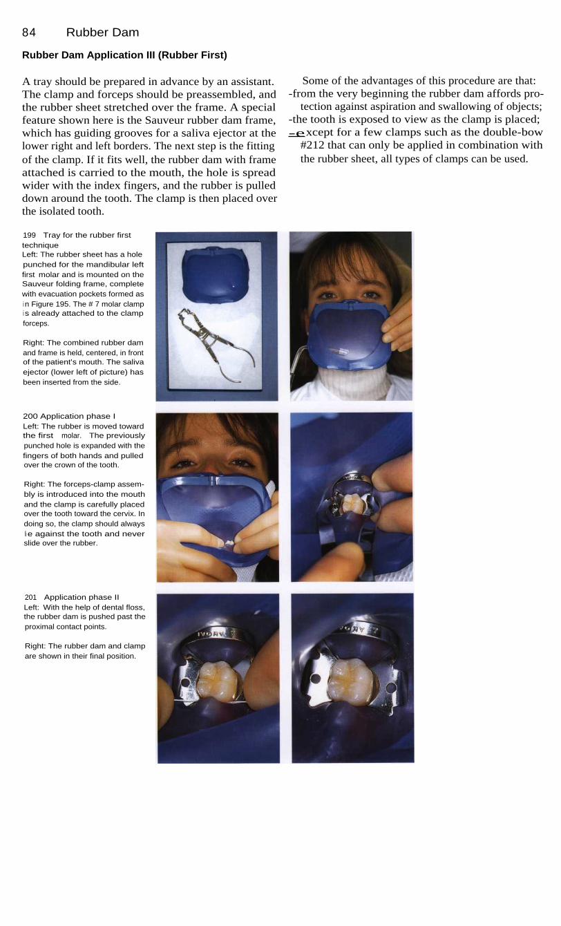
84
Rubber Dam
Rubber Dam Application III (Rubber First)
A tray should be prepared in advance by an assistant.The clamp and forceps should be preassembled, andthe rubber sheet stretched over the frame. A specialfeature shown here is the Sauveur rubber dam frame,which has guiding grooves for a saliva ejector at thelower right and left borders. The next step is the fittingof the clamp. If it fits well, the rubber dam with frameattached is carried to the mouth, the hole is spreadwider with the index fingers, and the rubber is pulleddown around the tooth. The clamp is then placed overthe isolated tooth.
Some of the advantages of this procedure are that:-from the very beginning the rubber dam affords pro-
tection against aspiration and swallowing of objects;-the tooth is exposed to view as the clamp is placed;-except for a few clamps such as the double-bow
#212 that can only be applied in combination withthe rubber sheet, all types of clamps can be used.
199
Tray for the rubber firsttechniqueLeft: The rubber sheet has a holepunched for the mandibular leftfirst molar and is mounted on theSauveur folding frame, completewith evacuation pockets formed asi n Figure 195. The # 7 molar clampi s already attached to the clampforceps.
Right: The combined rubber damand frame is held, centered, in frontof the patient's mouth. The salivaejector (lower left of picture) hasbeen inserted from the side.
200 Application phase ILeft: The rubber is moved towardthe first molar. The previouslypunched hole is expanded with thefingers of both hands and pulledover the crown of the tooth.
Right: The forceps-clamp assem-bly is introduced into the mouthand the clamp is carefully placedover the tooth toward the cervix. Indoing so, the clamp should alwaysli e against the tooth and neverslide over the rubber.
201 Application phase IILeft: With the help of dental floss,the rubber dam is pushed past theproximal contact points.
Right: The rubber dam and clampare shown in their final position.

Rubber Dam Application
85
Rubber Dam Application IV (Clamp First)
With this technique the clamp is placed on the toothfirst. As in application III, the two combinations ofclamp-forceps and rubber sheet-frame should be pre-assembled. Only the order in which they are brought tothe mouth is reversed. It is essential that the clamp besecured against the possibility of its slipping into thepharyngeal cavity. This is accomplished by looping along piece of dental floss over the bow of the clampand letting it hang out of the mouth where it can bequickly grasped in an emergency.
One special problem arises during placement of therubber dam in that the hole must be stretched wide topass over the selected clamp. Therefore, the use ofwingless clamps is recommended because their smallerwidth makes it less likely that the dam will tear. Onegreat advantage is the unobstructed view as the clampis being applied.
No matter which technique is used, the final step isto disinfect the operating field as for any surgical pro-cedure. Chlorhexidine is a suitable disinfecting agentfor dental use.
202 Clamp first techniqueA wingless clamp (Hygenic B 1),with a piece of dental floss at-tached to prevent aspiration, isplaced directly on the first molarusing a clamp forceps. As this isdone, the operator should feel theclamp pass over the height of con-tour and to the level of the gingiva,then slowly release the tension onthe clamp forceps.
203 Rubber-frame assemblyLeft: The rubber sheet has pre-viously been attached to the Sau-veur folding frame. The dam ispulled over the frame at the lowerl eft and lower right so that a water-proof pocket is formed on eachside. The folding frame shown hasa groove at the lower border thatcan serve as a guide and retainerfor a saliva ejector.
Right: Next, the rubber dam ispulled over the bow of the clamp.
204 Securing the damLeft: The fingers are used to pullthe rubber sheet over the lingualwing of the clamp.
Right: Finally, the rubber dam ispushed into the proximal spaceswith dental floss.

86
Rubber Dam
Special Cases
In a few cases, the techniques just described will haveto be modified in order to achieve a well-placed, tight-ly fitting rubber dam. Some aids such as dental floss,Wedjets, Kerr compound, or even a second clamp havealready been mentioned.
Patients with fixed orthodontic appliances pose spe-cial problems. Even in these difficult situations, it ispossible to place a rubber dam by using one's imagina-tion and ingenious variations of the accessory materi-als. Dental floss ligatures serve well here.
Teeth with fixed prostheses frequently need end-odontic treatment also. Where only a single tooth isinvolved, it is often a good idea to remove the crown toobtain a better view. If, as is frequently the case, theunderlying tooth is severely damaged, it may be neces-sary to attach the dam to the adjacent teeth or to em-ploy a clamp designed especially for deeply damagedteeth. For radiographic exposures it is often necessaryto unfasten part of the dam from the pegs on the frame.For these situations, the Sauveur folding frame with itshinges offers an elegant alternative.
205 Application of a rubberdam over a fixed orthodonticapplianceThe adaptation of the rubber sheetcan be difficult in many treatmentsituations. With some ingenuity,however, a solution can always befound.
Here, in spite of brackets, ligaturewire, tight spacing, and multipleangles, a rubber dam is success-fully applied by carefully pullingthe perforated dam over the teethand then securing it by means of aclamp on the canine and a dentalfloss ligature on the premolar.
206 Deep coronal destructionEven teeth with extensively damag-ed crowns can and should have arubber dam applied.
Left: Here, three holes are punchedi n the rubber dam that is anchoredby means of a clamp on each ofthe two teeth adjacent to the toothunder treatment. This tooth is thenexposed by tucking the border ofthe middle hole into the sulcus.
Right: This molar with no crown isi solated using a wingless clampwith a safety line of dental flossattached.
207 Radiograph with rubberdam in placeNormally the rubber dam framemust be partially or completely re-moved. The Sauveur folding framehas centrally placed hinges thatallow one side to be opened.
Left: The maxillary right first molaris isolated. This lateral view showsthe frame folded to the right side inpreparation for a radiograph.
Right: The patient is instructed tohold the film in the desired posi-tion with a hemostat.

87
Local Anesthesia
Local anesthesia is regarded as the primary form of pain control for endodontic treatment (Cavinoand Vasallo 1977, Lipp 1992). Only in extreme and exceptional situations is it necessary to useconscious sedation (e. g. with patients at risk because of medical conditions) or, more rarely,general anesthesia (e. g. absolute contraindication to local anesthetia) (Tolksdorf 1985, Daub-lander 1989 a, b). Lidocaine, mepivacaine, or articaine can be used for eliminating pain inendodontia, depending upon the depth of anesthesia required and the medical risk factors present.The types of injection used are infiltration and conduction (block) anesthesia, and less frequent-ly, intraligamental injection.
Topical anesthesia serves primarily to reduce thepain of the injection, which more than two-thirds ofpatients consider to be uncomfortable or anxiety pro-ducing. The local anesthetic of choice here is lidocaine,which is the only amide that has a strong topical effect.The mucosa should be dried first to enhance the effect.After spraying or swabbing the anesthetic onto themucosa, 2.5 or 3 minutes should be allowed for theonset of anesthesia.
For infiltration anesthesia the solution is injectedunder the mucosa to make direct contact with bone.Subperiosteal injection should be avoided because ofthe severe pain it produces. The local anesthetic mustdiffuse through spongy bone to the terminal nerveendings. This is possible only where the cortical layeris thin. Therefore, infiltration anesthesia can only beused in the maxilla of adults, but in both jaws of child-ren. In the mandible of children, 4% articaine isrecommended.
Conduction anesthesia makes it possible to anesthe-tize a large treatment area with only a small amount ofanesthetic. For successful conduction anesthesia it isnecessary to precisely deposit the anesthetic solutionimmediately adjacent to the corresponding nerve. Asmall deviation of the needle tip can lead to a "missedblock."
For an intraligamentary injection a very fine(0.3 mm) needle is introduced approximately 2-4 mminto the gingival sulcus (Einwag 1985, Erlemeier1990). Its alignment should be parallel to the long axisof the tooth. To anesthetize a tooth, multiple injections,each of approximately 0.2 ml of solution, are made me-sial and distal to the root. Four injections are made fora molar and two for other teeth. For most systems,0.2 ml corresponds to one stroke of the syringe. Duringthe actual injection, definite resistance should be feltbecause a "resistance free" injection means the needleis improperly placed. If the needle is not placed deepenough, anesthetic solution will flow out of the gingi-val sulcus and into the oral cavity. Furthermore, it is es-sential that the local anesthetic be injected slowly. It isrecommended that each injection take 20 to 30 se-conds. After the injection, the anesthetic solutionspreads to the marginal sections of alveolar bone and tothe surrounding gingiva. Results of recent research in-dicate that the pressure of an intraligamentary injectioncauses the anesthetic solution to enter the circulatorysystem. The anesthetic effect may be the result ofselective perfusion of the material into arterioles of thealveolar process and blocking of the nerve endings ofthe pulp and periodontium.

88
Local Anesthesia
Anesthetic Solutions
Lidocaine is the first classic amide preparation. It wasindtroduced into clinical use in 1948 and has becomethe most widely used local anesthetic around the world.Lidocaine has replaced procaine as the reference stan-dard for toxicity and effectiveness. Epinephrine is al-most always added as a vasoconstrictor because lido-caine alone is a strong vasodilator and would be rapidlycarried away from the injection site. Lidocaine with aadded vasoconstrictor produces profound pulpalanesthesia for 30 to 60 minutes and soft-tissue anesthe-sia for 120 to 150 minutes.
Mepivacaine was approved for use in 1960. It differsfrom lidocaine in that it can be used for local anesthesiawithout the addition of vasoconstrictors. This chemicalhas its own vascoconstrictor effect which, however, isnot very strong. Mepivacaine is the agent of choice forpatients with contraindications to added vasoconstric-tors, patients with an allergic predisposition, and asth-matic patients (no preservative or sulfite additives).The duration of anesthesia when no vasoconstrictor isadded is 20 to 40 minutes in the pulp and 45 to 90minutes in the soft tissues.
208 Anesthesia of thenasopalatine nerveThe anesthetic solution is depos-ited at the exit of the nasopalatinecanal directly under the incisivepapilla. Anesthesia extends throughthe palatal mucosa in the region ofthe incisor teeth.
Right: Field of anesthesia and in-j ection site.
209 Anesthesia of the posteri-or superior alveolar nerveThe needle is inserted near the tu-berosity at the posterior surface ofthe maxilla at an angle of approxi-mately 30° to all reference planes.The insertion depth is 0.5-1.0 cm.Contact with bone is verified be-fore depositing the solution.
210 Anesthesia of the posteri-or superior alveolar nerveAnesthesia is produced in the mo-lars and buccal gingiva of the max-i ll a. A complication can occur ifcontact with the bone is lost andthe needle is inserted too deeply,namely puncture of the maxillaryartery with formation of a retromax-illary hematoma. In the photographthe injection site and field ofanesthesia have been highlighted.

Anesthetic Solutions
89
Since its introduction 20 years ago, articaine hasbeen the dominant anesthetic agent in dentistry and isdistinguished by its good ratio of strength to toxicity(from 2.5-3). In addition to its long duration of actionwhen injected with epinephrine added (pulpal anesthe-sia 75-100 minutes, soft-tissue anesthesia up to 240minutes), it has a pronounced ability to penetrate bone.It is also the agent of choice in pregnant patientsbecause its high plasma protein binding ability reducesits passage across the placenta.
Epinephrine is the only vasoconstrictor worthrecommending. In concentrations of 1 : 100 000 or1 : 200 000 it exerts extensive vasoconstriction at theinjected area. Complications such as tachycardia, in-creased blood pressure, arrhythmias, and angina pecto-ris occur only with high doses or inadvertent intravas-cular injection. Because of its short plasma half-life(2-3 minutes) these symptoms are not prolonged,however. Norepinephrine is obsolete because of itssignificantly higher rate of side effects and the longerduration of its effect.
211
Anesthesia of themandibular nerveThe injection is made in the sulcuscolli mandibulae over the mandib-ular foramen approximately 1 cmabove the occlusal plane. Thisanesthetizes the teeth and thevestubilar mucosa in that half ofthe mandible, except for the buccalmucosa in the molar region.
212 Anesthesia of themandibular nerveA needle that is correctly positionedwill deposit the local anestheticsolution above the lingula and themandibular foramen. 1-1.5 ml solu-tion will provide satisfactory localanesthesia if the position is correct.
213 Problems with incorrectpositioningIf the tip of the needle stops ante-rior to the lingula (left) or is insertedbeyond it (right), the anestheticmay be deposited away from thetargeted nerve. A side effect ofinjection too far posteriorly isanesthesia of the facial nerve.
Figures 212-213 are taken from:Lipp, M.D.W. Die Lokalanasthesie.Berlin: Quintessenz Verlag; 1992.

90
Local Anesthesia
Selection Side Effects
Criteria for selecting a local anesthetic agent in the pres-ence of a systemic illness include the type and durationof the procedure and the experience of the operator withthe anesthetic agents under consideration. The recom-mendations below will serve as a decision-making aid.The decision for or against a particular agent must be anindividual one. To provide safe local anesthesia whenthere is suspicion of a cardiac risk factor and whenmonitoring is not available, it is prudent to employ theappropriate procedure; for example, unaugmented mepi-vacaine on patients with cardiac arrhythmia (Lipp 1992).
It is important to recognize the early signs of untowardreactions (such as a metallic taste from anesthetic in-toxication or increasing tachycardia because of a hy-persensitivity to epinephrine) and to implement appro-priate emergency procedures: discontinue injection,remove foreign objects, position the patient correctly,check (and if necessary, restore) the vital functions, andcall for qualified assistance. In the rare event of anemergency arising from local anesthesia, immediateemergency treatment by the dental team is crucial tothe outcome.
214 Anesthesia for surgicalendodontic procedures in themaxillaLeft: Anterior region.
Begin with injections at threeseparate sites labial to the targetedtooth (here, right central incisor),then inject into the palate for thenasopalatine nerve.
Right: Posterior region.Begin the injections buccal to
the targeted tooth (right secondmolar) and finish with a palatal in-j ection. The right half of the draw-i ng shows the injection for an op-eration on the lingual root of theleft first molar.
215 Anesthesia for surgicalendodontic procedures in themandibleLeft: Anesthesia in the posteriorregion.
The injections begin with a man-dibular block (conduction anesthe-sia of the mandibular canal),followed by injections buccal andlingual to the involved tooth.
Right: Anesthesia in the anteriorregion.
First, a mandibular block, follow-ed by additional labial and linguali njections.

91
Access Preparation
Root canal treatment begins with the creation of an access opening in the tooth, which should beperformed under a rubber dam. Difficulties in instrumenting the root canal are usually the resultof inadequate access preparation and lack of straight-line access to the root canals. Direct visual-ization into the canal orifice is essential. This is aided by the use of loupes or an operation micro-scope. A substantial amount of coronal tooth structure must be preserved, of course, and only asmuch enamel and dentin may be removed as is absolutely necessary. However, locating the en-trances to the canals must never be hindered by an access preparation that is too small. Mistakesin forming the access preparation can generate a multitude of problems throughout the entire end-odontic procedure. Among these mistakes is the failure to remove all caries as well as weak andunsupported tooth structure. Incomplete removal of inadequate and leaky fillings and crownsleads to contamination of the prepared root canals with saliva and, therefore, with bacteria. Lackof direct access to the root canal orifices can result in overstraightening of curved canals and per-forations. Knowledge of tooth and root canal anatomy is important to the proper formation of theaccess preparation because the access preparation should represent an elongated version of thepulp chamber.
Compromised treatment during root canal instru-mentation is usually the result of an inadequately form-ed access preparation. Endodontic treatment includesat the very beginning the complete removal of allcarious lesions and defective prosthetic restorations.Caries removal reduces the risk of bacterial contamina-tion of the root canals. Ortherwise, bacteria could betransported by an instrument from the coronal regioninto the apical portion of the canal and could set off apostoperative reaction. Insufficient excavation of car-ies and leaving old fillings or defective crowns in placecan result in diffusion of saliva and contamination ofthe root canal. Bacteria can thereby spread into the rootcanal system and penetrate unhindered into the apicalportions of the canal with long-term endodontic failureas a possible consequence.
Bacteria can penetrate as much as 700 hum into den-tinal tubules, attach themselves there, multiply rela-tively unhindered, and later initiate periapical inflam-mation and bone destruction (Perez et al. 1993). If oldrestorations are not completely removed, particles offilling material may become loosened during root canalinstrumentation and block the canal. If an existing fill-ing is intact and shows no evidence of leakage on theradiograph, it may be left in place. On the other hand,it is only through complete removal of previous resto-rations that the extent of carious penetration and thepresence of leaking margins can be determined for cer-tain, the canals can be found more readily, and straightline access for canal instrumentation can be facilitated.This does require additional effort in that either aninterim crown or an adhesively bonded filling mustbe made to protect the tooth from fracture betweenappointments (Gutmann et al. 1991).

92
Access Preparation
I nterim Restorations
Only those teeth that have a favorable prognosis andthat can be successfully restored should be included inthe endodontic treatment plan.
After removal of all previous restorations, it isdesirable to construct an interim restoration. This willprovide a coronal reference point for determining theworking length, as well as protect the tooth from anoverload fracture between appointments. Furthermore,a tight seal against the oral environment is important inpreventing contamination with salvia. The interim res-toration can be a direct composite filling, a composite
inlay with adhesive cement, or a cemented syntheticresin crown. The latter can also serve as a short-term orlong-term provisional restoration. The amount of toothstructure missing and the length of time the restorationmust be worn determine which type should be used.Glass ionomer cements provide very good marginaladaptation initially, but during function they undergoextensive occlusal wear and deterioration of marginalintegrity (Krejci et al. 1996b).
216 Destruction of hardtissuesThe hard structures of the teethhave been severely damaged andmust be restored before root canaltreatment is started. The first andsecond premolar both show inade-quate amalgam restorations. Themissing cusp will make the build-up more difficult.
Right: A crown with impermeablemargins must be placed so that areproducible working-length mea-surement can be established.
217 RadiographOn this diagnostic radiographtaken at the beginning of rootcanal treatment, destruction of thetooth structure of the secondpremolar is evident. The periapicalregion appears normal. Radio-graphically the root canal filling inthe first premolar appears intactand well condensed. Retreatmentis not necessary.
218 Preparation andi mpressionThe filling in the second premolaris completely removed. The shapeof the cavity preparation is largelydictated by the extensive loss oftooth structure. Next, a sectionali mpression is made to include theaffected tooth as well as the twoi mmediately adjacent teeth.
Right: Making of the impressionwith an addition reaction siliconematerial. Finally, a direct compos-i te provisional restoration is madeat chairside.
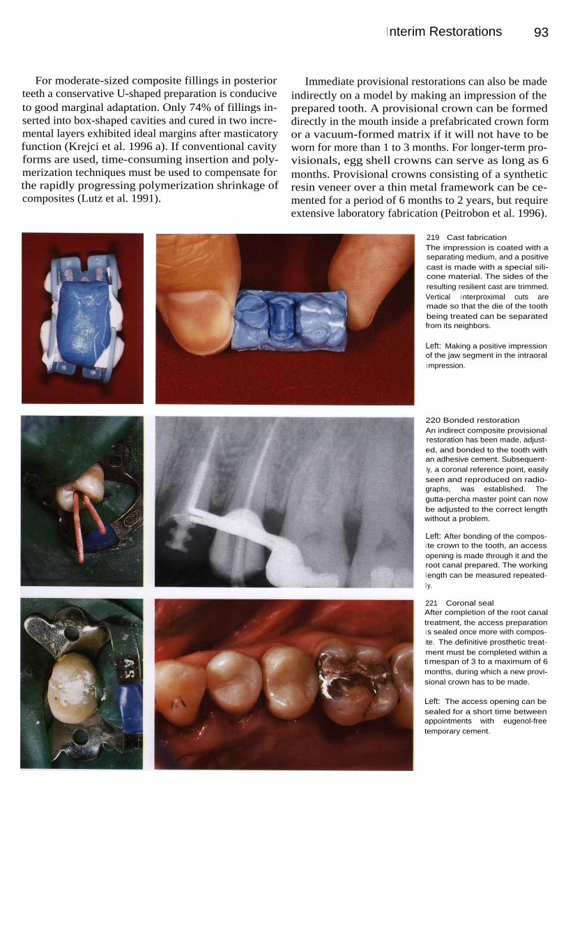
I nterim Restorations
93
For moderate-sized composite fillings in posteriorteeth a conservative U-shaped preparation is conduciveto good marginal adaptation. Only 74% of fillings in-serted into box-shaped cavities and cured in two incre-mental layers exhibited ideal margins after masticatoryfunction (Krejci et al. 1996 a). If conventional cavityforms are used, time-consuming insertion and poly-merization techniques must be used to compensate forthe rapidly progressing polymerization shrinkage ofcomposites (Lutz et al. 1991).
Immediate provisional restorations can also be madeindirectly on a model by making an impression of theprepared tooth. A provisional crown can be formeddirectly in the mouth inside a prefabricated crown formor a vacuum-formed matrix if it will not have to beworn for more than 1 to 3 months. For longer-term pro-visionals, egg shell crowns can serve as long as 6months. Provisional crowns consisting of a syntheticresin veneer over a thin metal framework can be ce-mented for a period of 6 months to 2 years, but requireextensive laboratory fabrication (Peitrobon et al. 1996).
219
Cast fabricationThe impression is coated with aseparating medium, and a positivecast is made with a special sili-cone material. The sides of theresulting resilient cast are trimmed.Vertical i nterproximal cuts aremade so that the die of the toothbeing treated can be separatedfrom its neighbors.
Left: Making a positive impressionof the jaw segment in the intraorali mpression.
220 Bonded restorationAn indirect composite provisionalrestoration has been made, adjust-ed, and bonded to the tooth withan adhesive cement. Subsequent-ly, a coronal reference point, easilyseen and reproduced on radio-graphs, was established. Thegutta-percha master point can nowbe adjusted to the correct lengthwithout a problem.
Left: After bonding of the compos-i te crown to the tooth, an accessopening is made through it and theroot canal prepared. The workingl ength can be measured repeated-l y.
221
Coronal sealAfter completion of the root canaltreatment, the access preparationi s sealed once more with compos-ite. The definitive prosthetic treat-ment must be completed within atimespan of 3 to a maximum of 6months, during which a new provi-sional crown has to be made.
Left: The access opening can besealed for a short time betweenappointments with eugenol-freetemporary cement.

9 4
Access Preparation
Opening the Pulp Chamber
Besides insufficient preparation of the access cavity, aprimary source of problems in opening into the pulpchamber is incorrect estimation of the angle betweenthe long axes of the crown and root. This makes findingthe entrances to the canals more difficult. The diagnos-tic radiograph is helpful in locating the canal orifices.When large restorations are present, an additionalbitewing radiograph should be taken. To help avoidperforation or excessive dentin removal at the floor ofthe cavity, the alignment of the diamond cutting instru-ment should be determined on the radiograph.
The first depth cut is made with a round diamondstone, while cylindrical burs are good for extending thecavity laterally. A useful combination of instrumentsfor making the entire access preparation is the EndoAccess bur by H. Martin (Maillefer) and a cylindricalor tapered fissure bur with a rounded, noncutting end.If trouble is encountered in finding the canal orifices,the largest root canal is used for orientation. The floorof the coronal pulp chamber gives clues to the numberand location of the canal orifices by its ridges and de-pressions. The roof must first be completely removed.
222 Rotary instrumentsLeft: Spherical and cylindrical dia-mond cutting instruments that canbe used for making the accesspreparation. The Endo Access burby Dr. Martin (right) is ideal.
Center: Round burs with differentshaft lengths.
Right: Cylindrical and taperedburs with smooth, round ends aresimilar to ordinary fissure bursexcept for the noncutting tip thatprevents perforating the floor ofthe pulp chamber.
223 Uncovering and probingcanal orificesLeft: The most important instru-ments for finding a root canal en-trance are long, rigid explorers thatdo not penetrate into sound dentinbut will catch in a canal orifice,and so help locate it.
Center: Hand instruments forprobing and locating root canalentrances.
Right: Spoon excavators are usedto remove soft-tissue remnantsfrom the floor of the pulp chamber.
224 Exploring and enlargingLeft: If the explorer catches in den-tin at the floor of the access prep-aration, a fine file of size 6, 8, or 10or a Pathfinder is used to deter-mine whether a root canal or aperforation is present.
Center: Gates-Glidden drills areused for the initial coronal enlarge-ment of canals. The size is indicat-ed by the number of rings.
Right: Differing shapes of instru-ments for enlarging canal en-trances (Gates, Peeso).

Uncovering the Canal Entrances
95
Uncovering the Canal Entrances
The circumferential form of the endodontic accesspreparation should correspond to the outline of the roofof the pulp chamber. The cavity outline form in maxil-lary incisors is triangular and lies in the center of thelingual surface. It must be widely extended mesiallyand distally to include all of the pulp horns and allowremoval of any soft-tissue remnants. Any tissue left be-hind can later cause discoloration of the clinical crown.The pulp chamber is prepared at a 45° angle to the longaxis of the tooth (Peters 1992 a).
The outline form of the access preparation on man-
dibular molars is trapezoidal. The cavity is started inthe center of the tooth with the axis of the bur directeddistally because the space over the distal canal is theeasiest to locate (Peters 1992 b).
In maxillary molars the access preparation beginscentrally with the bur directed toward the mesiolingualcusp where the pulp space is greatest. After the pulpchamber is reached, the cutting instrument is movedbuccally, maintaining noncutting contact with the floorof the pulp chamber, to remove the overhanging roof(Peters 1992 c).
225 Access preparations inmaxillary teethLeft: Anterior teeth are openedfrom the lingual aspect. The cavityis triangular and the canal, usuallysingle, lies in the center of thetooth.
Center: In premolars the prepara-tion is oval-shaped and orientedbuccolingually.
Right: The access preparation formaxillary molars is rhomboidal ortrapezoidal. The majority have afourth orifice opening into a mesio-li ngual canal in the mesiobuccalroot.
226 Overall view of possiblecanal locationsThe drawings of the maxilla (left)and the mandible (right) show thenumber of root canals commonlyencountered at the floor of thepulp chamber and their usual po-sitions in relation to the occlusalsurface..
227 Access preparations inmandibular teethLeft: Mandibular anterior teethhave two root canals in up to 25%of cases. A triangular preparationis made from the lingual.
Center: Premolars are openedwith a buccolingually orientedoval-shaped access preparationthrough the occlusal surface.
Right: In mandibular molars theopening should be trapezoidal,usually wider mesially than distally,and bordered mesially by the mar-ginal ridge.
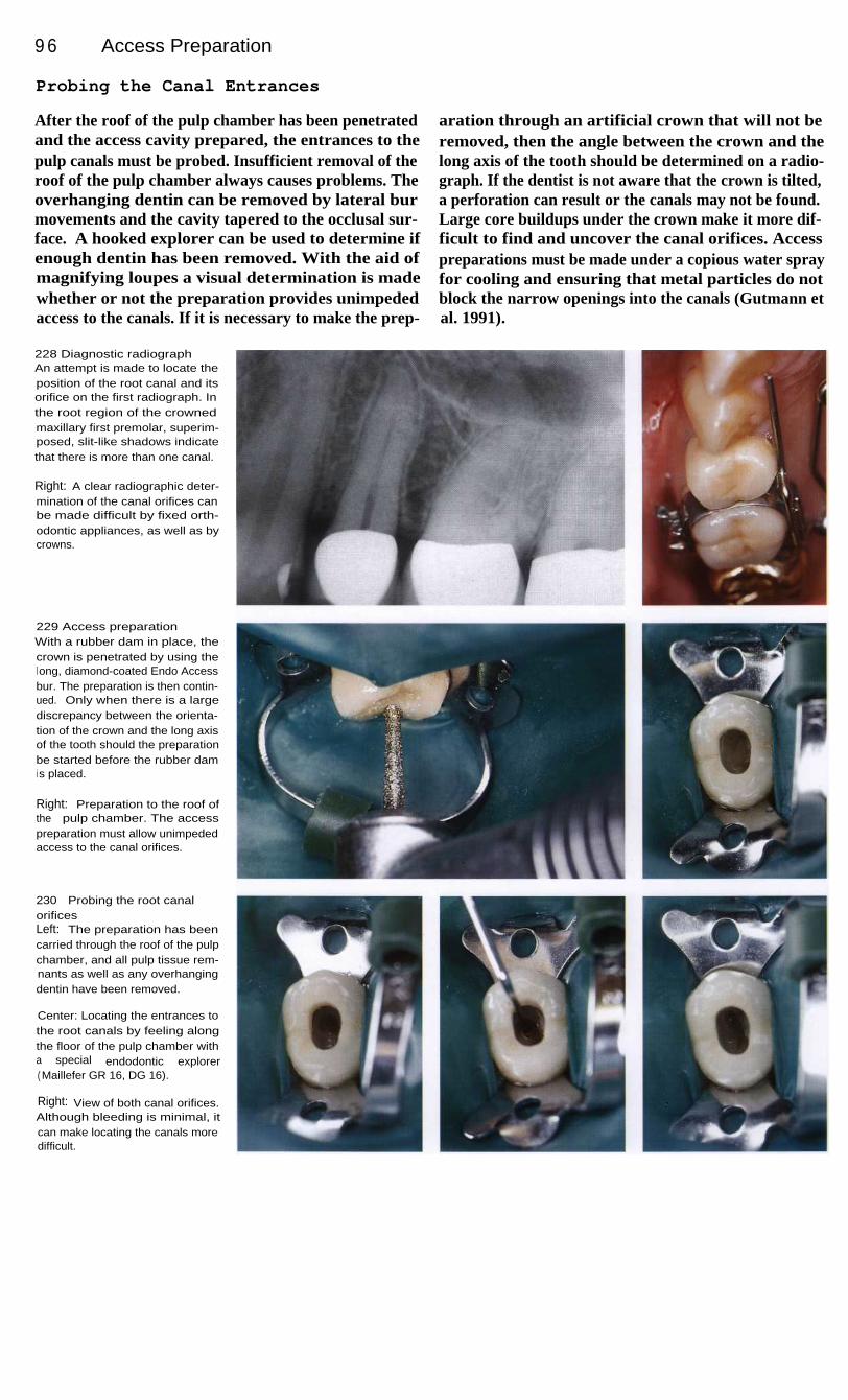
9 6
Access Preparation
Probing the Canal Entrances
After the roof of the pulp chamber has been penetratedand the access cavity prepared, the entrances to thepulp canals must be probed. Insufficient removal of theroof of the pulp chamber always causes problems. Theoverhanging dentin can be removed by lateral burmovements and the cavity tapered to the occlusal sur-face. A hooked explorer can be used to determine ifenough dentin has been removed. With the aid ofmagnifying loupes a visual determination is madewhether or not the preparation provides unimpededaccess to the canals. If it is necessary to make the prep-
aration through an artificial crown that will not beremoved, then the angle between the crown and thelong axis of the tooth should be determined on a radio-graph. If the dentist is not aware that the crown is tilted,a perforation can result or the canals may not be found.Large core buildups under the crown make it more dif-ficult to find and uncover the canal orifices. Accesspreparations must be made under a copious water sprayfor cooling and ensuring that metal particles do notblock the narrow openings into the canals (Gutmann etal. 1991).
228 Diagnostic radiographAn attempt is made to locate theposition of the root canal and itsorifice on the first radiograph. Inthe root region of the crownedmaxillary first premolar, superim-posed, slit-like shadows indicatethat there is more than one canal.
Right: A clear radiographic deter-mination of the canal orifices canbe made difficult by fixed orth-odontic appliances, as well as bycrowns.
229 Access preparationWith a rubber dam in place, thecrown is penetrated by using thel ong, diamond-coated Endo Accessbur. The preparation is then contin-ued. Only when there is a largediscrepancy between the orienta-tion of the crown and the long axisof the tooth should the preparationbe started before the rubber dami s placed.
Right: Preparation to the roof ofthe pulp chamber. The accesspreparation must allow unimpededaccess to the canal orifices.
230
Probing the root canalorificesLeft: The preparation has beencarried through the roof of the pulpchamber, and all pulp tissue rem-nants as well as any overhangingdentin have been removed.
Center: Locating the entrances tothe root canals by feeling alongthe floor of the pulp chamber witha special endodontic explorer( Maillefer GR 16, DG 16).
Right: View of both canal orifices.Although bleeding is minimal, itcan make locating the canals moredifficult.

Probing the Canal Entrances
97
The canal entrances are found by feeling with a thin,stiff explorer. If the explorer sticks in a spot, a size 15Hedstr6m file is used to verify that the spot is indeedthe entrance to a root canal and not a perforation. Onlythen is the opening gently enlarged. Narrow root canalsmust first be enlarged coronally with a Hedstr6m filebefore the deep preparation can be started. While Kfiles are certainly flexible enough to get past curvesand calcifications, they do cause blockages within theroot canal more frequently.
Because the 16-mm-long cutting segments of the in-struments are about 0.32 mm larger in diameter nearthe handle than at the tip, they frequently bind in themidroot area. For this reason, a narrow root canal is en-larged in segments by advancing the instrument 1 mmat a time, aided by a chelating agent. Only after thecanal is made patent is the coronal portion preparedwith a Gates-Glidden drill. The entire root canal canthen be instrumented without problems.
231
I nitial enlargementLeft: The entrance to the canal iscarefully widened with a smallGates drill.
Center: Working millimeter by milli-meter from the coronal opening to-ward the apex with a size 15 Hed-str6m file, the canal is carefullyenlarged as necrotic pulp tissue isremoved. No attempt is made towiden an area before it can bepenetrated.
Right: View into the cavity showingthe widened coronal portions ofboth canals.
232 Length determinationAfter the initial coronal enlarge-ment and before preparing thedeeper apical portion of the rootcanals, the length is measured ona radiograph. (The fixed orthodon-tic appliance interfered with pre-cise placement of the X-ray film.)
Left: For easier differentiation onthe radiograph, different types ofi nstruments were inserted into thetwo root canals: a Hedstr6m file inthe lingual and a Flexicut file in thebuccal canal.
233 Root canal treatmentAfter preparing both canals, theyare filled with gutta-percha and asealer, and the result of the treat-ment is evaluated by means of afinal radiograph.
Left: Following determination ofthe working length, instrumentationis continued before the canals arefilled.

9 8
Access Preparation
Straight-Line Access to the Canals
Initial penetration of the pulp chamber of an uppermolar is made over the orifice of the lingual canal. Thecavity is then extended to its final outline. The lingualcanal serves as a reference point for finding the othercanals. The diamond-cutting instrument is moved buc-cally while contacting the floor of the pulp chamber inorder to remove the overhanging roof and uncover themesiobuccal and distobuccal canals. The preparation isthen completed using a smooth-tipped cutting instru-ment. The cavity walls should be made to divergeslightly (Peters 1992 a-d).
The final shape creates unimpeded access to all rootcanals. This is the only way to ensure that the instru-ments can be inserted straight into the canals. Becausemany canals are curved at their coronal ends, thecervical ledge, or coronal bulge, must be carefullyremoved. In cases where the pulp chamber is difficultto find, the cavity is dried and the preparation isextended to a depth of 2 mm toward the presumedlocations of the canal orifices by means of a slowlyrotating round bur. Chelating agents are of no real helpin finding the entrances to canals.
234 Radiographic diagnosisMaxillary first molar with deep,penetrating secondary caries onthe distal surface. The depth of thecavity can be determined from itsrelation to the proximal box of therestoration.
Right: Emergency pulp extirpationat the first appointment: only thecanal orifice that was easiest tofind is opened, and the largest rootcanal (here the lingual) instrument-ed.
235 Working-lengthradiographTo avoid superimposition of the lin-gual root canal on the radiograph,the buccal root canals may bemeasured separately. The over-hanging dentin has yet to be com-pletely removed.
Right: Removal of the old crownfacilitates removal of all caries anddentin overhangs and createsstraight-line access for the instru-ments.
236
Preparation of the rootcanalsThe root canal instruments mustbe able to enter the root canals ina straight line and pass unimped-ed to the working length.
Right: I nitial situation before mak-i ng the access preparation. Thisshows the dentin overhanging theentrances to the root canals thatwill have to be removed before thecanals are instrumented.

Straight-Line Access to the Canals
99
The floor of the pulp chamber lies 1-2 mm below thelevel of the cementoenamel junction. If the location ofthe pulp chamber is difficult to find, the distance can bemeasured on a radiograph and transferred to the EndoAccess bur. Measurements made with a periodontalprobe are also helpful for avoiding perforations. Nor-mally, maxillary first molars have three roots with fourroot canals; the fourth canal, the mesiolingual, is locat-ed in the mesiobuccal root. Images of the two mesialcanals may be superimposed on the radiograph. Theycan be better differentiated on an eccentric projection.
One complication is the curvature to the distal andlingual near the apex. Before instrumenting this por-tion, the direction of the curve must be determinedtactually with a prebent instrument. First, the notch onthe rubber stop is turned to face in the direction of thebend and then the instrument is inserted into the canal.The mark on the stop will indicate the course of thecanal and the direction of the curve. The stop providesthe only check on the orientation of the instrumentwithin the root canal.
237 Coronal enlargementThe three root canals are first en-l arged in their coronal portionsand then fully prepared. Visibilityi nto the cavity is excellent, andunimpeded i nstrumentation ispossible.
Left: The walls of the access prep-aration have been made parallelso that the instrument can passi nto the root canal in a straightl i ne.
238
Root canal fillingRemoval of the old restoration, agenerous access preparation, andunimpeded root canal preparationfacilitate fitting and adjusting of thethree gutta-percha points withease.
Left: At the conclusion of lateralcondensation, the portions of thegutta-percha points protrudingcoronally are removed.
239 Follow-up radiographSix months after the beginning ofroot canal treatment and beforecementation of the permanentrestoration, the periapical regionappears normal on the radiograph.
Left: The radiograph taken imme-diately after treatment shows adense root canal filling that sealsthe canals completely.

100
Access Preparation
Obliterated Root Canals
The ability of pulp tissue to form hard tissue is not lim-ited to the odontoblastic layer. Fibrodentin can also bedeposited in the center of pulp tissue as denticles (pulpstones). These can be found not only in erupted teethbut also in teeth that are still unerupted, in deciduous aswell as permanent teeth, and in both young and oldteeth (James et al. 1959).
With increasing age comes increased formation ofintrapulpal dentin with narrowing of the root canals.These hard-tissue formations are mostly the result ofinflammatory processes. With the exception of well-
organized tubular denticles that are formed by odonto-blasts, atubular osteoid or lamellar dentinoid hard-tissue formations consist of fibrodentin. They arethought to be formed by spaced pulpoblasts that areidentical to the mesenchymal cells of the dental papil-la (Baume 1980). There are different hypothesesregarding the origins and classification of denticles. Inresponse to external influences some cells within thepulp die, and concentric denticles form around them.Temperature changes may also play a role.
240
Preoperative clinicalappearanceClinical appearance of a 63-year-old patient before replacement offixed restorations.
Right: Removal of the cosmeticallyand functionally unsatisfactoryfixed partial denture extendingfrom the maxillary right canine tothe left first premolar reveals apost-core on the first premolar.
241
Preoperative radiographicappearanceThe second premolar appears tohave a single root canal with ani nadequate root canal filling and adistinct periapical radiolucency.The first premolar has a post-corethat is much too short and no rootcanal filling. The root canal is par-tially obliterated and barely identi-fiable.
Right: Opening through the artifi-cial crown on the second premolarunder copious water spray.
242
Root canal situationAfter making an access prepara-tion through the metal-ceramiccrown on the second premolar, lowmagnification loupes are used tofind a single canal that has beenfilled with cement and one gutta-percha point according to the cen-tral point technique.
Right: The inadequate root canalfilling of gutta-percha and cementis removed and the canal flushedwith sodium hypochlorite solution.
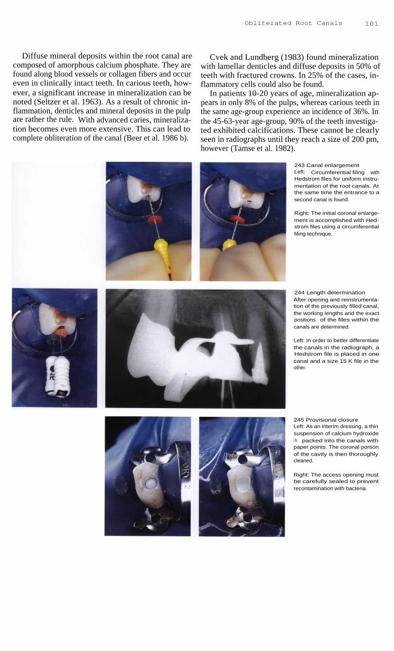
Obliterated Root Canals
101
Diffuse mineral deposits within the root canal arecomposed of amorphous calcium phosphate. They arefound along blood vessels or collagen fibers and occureven in clinically intact teeth. In carious teeth, how-ever, a significant increase in mineralization can benoted (Seltzer et al. 1963). As a result of chronic in-flammation, denticles and mineral deposits in the pulpare rather the rule. With advanced caries, mineraliza-tion becomes even more extensive. This can lead tocomplete obliteration of the canal (Beer et al. 1986 b).
Cvek and Lundberg (1983) found mineralizationwith lamellar denticles and diffuse deposits in 50% ofteeth with fractured crowns. In 25% of the cases, in-flammatory cells could also be found.
In patients 10-20 years of age, mineralization ap-pears in only 8% of the pulps, whereas carious teeth inthe same age-group experience an incidence of 36%. Inthe 45-63-year age-group, 90% of the teeth investiga-ted exhibited calcifications. These cannot be clearlyseen in radiographs until they reach a size of 200 pm,however (Tamse et al. 1982).
243 Canal enlargementLeft: Circumferential filing withHedstrom files for uniform instru-mentation of the root canals. Atthe same time the entrance to asecond canal is found.
Right: The initial coronal enlarge-ment is accomplished with Hed-strom files using a circumferentialfiling technique.
244 Length determinationAfter opening and reinstrumenta-tion of the previously filled canal,the working lengths and the exactpositions of the files within thecanals are determined.
Left: In order to better differentiatethe canals in the radiograph, aHedstrom file is placed in onecanal and a size 15 K file in theother.
245 Provisional closureLeft: As an interim dressing, a thinsuspension of calcium hydroxidei s packed into the canals withpaper points. The coronal portionof the cavity is then thoroughlycleaned.
Right: The access opening mustbe carefully sealed to preventrecontamination with bacteria.

102
Access Preparation
Locating Canals with the Surgical Operation Microscope
The surgical operation microscope has been used formicrosurgical procedures in the head and neck regionfor years. Microsurgery was introduced approximately38 years ago in a report by Jacobsen and Suarez (1960)in which they described suturing tiny blood vesselsunder a microscope. As much as 40 years earlier, otor-hinolaryngologists had recognized that operations onthe smallest structures were limited primarily by thecapacity of the human eye. Nylen employed a mono-cular microscope for surgery on the inner ear as earlyas 1924.
Viewing the root canal by means of a surgicalmicroscope demanded a completely new system of in-strument use. The operator must work in the 12-o'clockposition with the help of a mirror for both maxillaryand mandibular teeth, and the working time is signifi-cantly increased. The working field must be dried morefrequently for a better view. A specially developed irri-gating syringe (Stropko, EIE) is well suited for this.The surgical operation microscope is brought intoposition to search for the canal orifices only after theaccess cavity has been prepared.
246 Access preparationWith the use of a surgical opera-tion microscope at 10x magnifica-tion, two separate root canals canbe seen in the second premolar,which appears on the radiograph(Fig. 241) to have only one canal.
247 Locating obliterated canalentrancesI n the clinical case described onpages 100 and 101, the two sepa-rate root canal orifices can beseen very clearly under highermagnification.
Also, the floor of the pulp cham-ber can be probed and the straightportions of the root canals can befollowed visually.
Right: Evaluation of the accesspreparation under 25x magnifica-tion.
248
Filling the root canalsFollowing completion of instru-mentation, the two gutta-perchamaster points are fitted. Their exactposition is then checked with arad iogaph.
Right: The working length is mark-ed on the gutta-percha points bymarking them with cotton pliers.Both points are then placed intothe canals.

Locating Canals with the S urgical Operation Microscope 103
Once the entrance to a root canal has been located, asize 08 K file, 21 mm long, is slowly inserted. A size10 instrument is too thick for the initial entry and a size06 is too flexible. The apical portion of the instrumentis prebent and the direction of the bend is identified bythe notch on the rubber stop. The 21-mm size 08 file isflexible enough to work past calcifications and curveswithout contributing to an iatrogenic blockage. Duringthe preparation a switch can then be made to larger andlonger instruments.
The instrument is inserted into the root canal withonly light pressure. The correct position and insertiondepth must be repeatedly checked with measurementradiogaphs in order to prevent creating a false path.Each time the file is removed, it is thoroughly cleanedand sterilized before reinsertion. Copious irrigationwith sodium hypochlorite will not only remove dentinfilings but will also dissolve the pulp tissue. Ultrasonicfiles must not be used until after the working length hasbeen reached with hand instruments (Gutmann et al.1991).
249 Radiographic evaluationBy using an eccentric radiographthe two separate root canal fillingscan be easily followed all the wayto the radiographic foramina.
Left: Before the final filling of theroot canals, they are thoroughlydried with paper points and evalu-ated once more with the surgicaloperation microscope.
250 Opening obliterated rootcanalsLeft: One canal of the first premo-lar (case presented in Fig. 240) iscarefully opened millimeter bymillimeter using a K file and achelating agent.
Center: A radiograph is taken todetermine the location of the file.When the correct working lengthhas been reached it is measuredand recorded.
Right: A final radiograph is takeni n the orthoradial direction to eval-uate the root canal filling.
251
Radiographic follow-upOn this radiograph taken at aneccentric angle 4 months after rootcanal treatment, two separatecanals can be clearly distinguish-ed in each of the two maxillarypremolars. Those of the first pre-molar unite shortly before the apexto form a single canal.

104
Access Preparation
Chemical Aids
Some of the dangers associated with the initial instru-mentation of curved root canals are blockage with den-tin chips, excessive apical enlargement, and perfora-tion. Obstructions in the apical regions of root canalsare seldom present before treatment is started. Themajority are created by improper instrumentation.These obstructions can only rarely be overcome. Alubricant that contains ethylendiamine tetraacetic acid(EDTA) should be used prophylactically to avoid creat-ing obstructions.
Such lubricants can prevent compaction of pulp-tissue remnants and dentin fillings until the coronalportion of the canal has been enlarged enough to permitsufficiently deep penetration of the irrigating solution.As early as 1957, Nygaard-Ostby employed the chelat-ing agent as an aid in endodontic instrumentation. Itdecalcifies dentin by binding the calcium in an electro-negative complex, and in this way can overcomeblockages within the root canal (Burck 1988).
252 Obliterated canalsMandibular first molar with peri-apical radiolucency and necroticpulp. On the radiograph it appearsthat all canals are patent. What ap-pears to be a pulp exposure thathas been directly capped can beseen in the mesial part of thecrown.
Right: After removal of the crown,the orifices of the root canals,especially that of the distal, werenot easy to identify.
253 Locating the canalsAfter successful location of theentrances to the canals with an ex-plorer, the distal canal proves to beblocked so that the file cannot bei nserted into the entire length ofthe canal. On the first working-l ength radiograph the shallowpenetration depth can be seen,although the file is within the rootcanal.
Right: Before penetrating deeper,the length of the root canal mustbe determined with a measuringgauge.
254 Overcoming obstructionsi n the root canalsThe second working-length radio-graph shows that both mesialcanals have been penetrated,though not yet all the way to theapical constriction. The distalcanal is still largely blocked.
Right: I ntraoral view of files inplace for radiographic determina-tion of their progess.

Chemical Aids
105
EDTA can increase dentin permeability and therebyhave a positive effect of the debridement of the rootcanal (Goldberg and Abramovich 1977). Because ofthe slow action of this hard-tissue demineralizingagent, decalcification of the dentin is not very apparent.Stewart et al. (1969) recommended use of the productRC-Prep (Premier Dental; 15% EDTA and 10% ureaperoxide in a water-soluble glycol base) during instru-mentation. RC-Prep has a very good lubricating andcleansing action.
To establish initial penetration of an obliterated rootcanal, the tip of a K file is moistened with a smallamount of RC-Prep and then inserted into the rootcanal with small rotating motions. Working past anobstruction is very time-consuming. Immediately afterremoval from the canal, the file must be carefullycleaned with a sterile gauze sponge. Finally the canal isflushed with Sodium hypochlarite solution that in-creases the dentin permeability, releases more oxygen,and neutralizes the EDTA.
255 Coronal enlargementUsing K files and gentle quarter-turn motions, the distal canal is in-strumented until clear passage isachieved. In order to avoid block-ages, file sizes are increased byhalf steps.
Left: Once the root canal has beenmade patent manually, it is careful-l y enlarged with Gates-Gliddendrills so that the working part ofthe files will not bind.
256 Chelating agentsDeeper penetration was not possi-ble without the help of a chelatingagent for demineralizing and lubri-cating the canals. On the radio-graph, penetration of the mesialcanals appears to be almost com-plete, but the distal file is still wellshort of the final working length.
Left: RC-Prep contains EDTA andurea peroxide. It has very goodl ubricating and cleansing proper-ties.
257 Working depthThe obliteration is finally clearedafter a lengthy procedure usingfinger instruments and the chemi-cal solution. The fourth radiographverfies that pasage through thecanal has been achieved.
Left: Different types of files are in-serted into the two mesial canalsfor easier radiographic differentia-tion. The stops are set at the coro-nal reference point.

106
Access Preparation
258 InstrumentationLeft: Enlargement of the rootcanals is started with a size 15 Kfile to the working length as deter-mined on the radiograph.
Right: Because the canals are nar-row and more sharply curved inthe apical region, it is necessary touse intermediate-sized files in thei nitial phase of instrumentation. Toavoid creating a blockage, instru-ment sizes are not increased byfull-step increments until after size
1 7.5.
259 Conical shapingThe root canal is prepared throughthree of four instrument sizes andthen enlarged more coronally tocreate a conical form. Notice thealmost circular and substantiallywider cross-section of the rootcanals.
Right: The conical canal form canbe achieved either with the step-back technique using only K filesor by engine-driven instrumenta-tion.
260 Root canal obturationAfter drying the canal it is tightlypacked with gutta-percha and asealer. The excess is then removedat the level of the canal orifices.
Right: The root canals are filledwith gutta-percha using the lateralcondensation technique.
261 Final radiographAfter filling all three canals, thedistal canal is prepared for athreaded post-core which is ce-mented at the same sitting. Aradiograph is taken to evaluate theendodontic treatment. Comparisonwith the initial radiograph (Fig.252) shows that it is possible toachieve good length and enlarge-ment of the canals even thoughthey were originally very narrowand partially obliterated.

107
Root Canal Preparation
The goals of root canal preparation are to clean all bacteria and necrotic pulp-tissue remnantsfrom the canal and to give it a shape that will allow the entire canal to be filled with a biologi-cally inert material. The preparation should extend to the narrowest part of the root canal, theapical constriction. The prognosis of root canal treatment is then clearly at its best (Beer andBaumann 1994 a).
In most teeth the apical constriction corresponds to the dentinocemental junction, which is wherethe dentin of the root canal meets cellular cementum. The apical foramen is the circumference atthe end of the root canal where pulp tissue is continuous with the apical periodontal tissue.
In 1931, Grove recommended the dentinocemental junction as the ideal end-point for rootcanal preparation. Kuttler (1955) further developed this idea with his extensive histologicinvestigation on more than 400 teeth, and described very precisely the location of the apicalconstriction and its relationship to the apical foramen. In 56% of the teeth studied the dentino-cemental junction was found to be at the same level on both sides of the root canal. In the re-maining teeth it lies at different levels on the two sides of the canal. The mean distance betweenthe center of the apical foramen and the apical constriction in people younger than 25 years of agewas 0.52 mm, and 0.66 mm in those older than 55 years. However, the reference point for thismeasurement was not the radiographic apex.
262
Details of the apexA Histologic section of the lingual
root canal of a maxillary firstmolar with necrosis and ulcerat-i ng pulpitis. The root canal ispartially constricted by hard tis-sue, contains pathologic calci-fications, and has an S-shapedcurvature with a bend to thedistal near the apex.
B The constriction above the api-cal foramen lies at the level ofthe dentinocemental junction.The apical foramen opens later-ally above the anatomic apex.
C This enlarged section shows thedentinocemental junction thatlies at different levels on the twosides of the apical constriction.

108
Root Canal Preparation
Radiographic Length Determination
The root canal preparation should end shortly beforethe apex. The anatomic apex is defined as that point onthe root that is farthest from the incisal edge or occlu-sal surface. The radiographic apex, on the other hand,is the furthermost point on the radiograph. Its locationmay be different from that of the anatomic apex. Theapical foramen is the opening at the end of the rootwhere pulp tissue and periodontal tissue merge. Theapical constriction lies within the root canal just coro-nal to the apical foramen and represents the narrowestpart of the canal (Simon 1993b).
The exact determination of the working length is oneof the most important steps in endodontic treatment andmakes the difference between success and failure. Thisdetermination can be made on the radiograph and maybe supported by tactile feedback and electronic aids.Blood or exudate on the paper point while the canal isbeing dried are also important clues to the workinglength. Blood on the tip is evidence of excessive enlar-gement of the apical foramen with overinstrumentation,while blood on the side of the paper point indicates aslit-like lateral perforation (Beer 1995).
263 Diagnostic radiographA radiograph taken before treat-ment for diagnostic purposes canprovide information on the ana-tomy of the root canals.
Right: Schematic representation ofthe anatomic details in the apicalregion showing the apical constric-tion (2) as the narrowest part of theroot canal and the anatomic apex(3). Necrotic and infected tissuemay be present between the be-ginning of the apical curve (1) andthe apical constriction.
264 First working-lengthradiographAfter making an access opening inthe lower second molar and identi-fying the canal orifices, the rootcanals were probed. The two mesi-al canals are superimposed andso they were measured one at atime. The K file in the mesiobuccalcanal is 2 mm too short.
Right: The next measurement ofthe distal and mesiolingual canalsshows that the preparations in bothof these canals are also too short.
265 Measurement correctionMeasuring instruments for transfer-ring the determined working lengthto the root canal instruments.
Above left: Guldener measuringblock. Below this is a measuringdevice (Maillefer) to be worn overthe ring finger.
Right: Ruler with a sponge to holdfiles (by Buchanan).

Radiographic Length Determination
109
Because the apical constriction cannot be directlydetermined on the radiograph, the tooth length is deter-mined by the distance between a coronal referencepoint and the radiographic apex. For this a radiopaqueobject must be placed in the root canal. The working-length radiograph with a size 15 steel file inserted intothe canal(s) provides information on, among otherthings, root canal anatomy, the number of root canals,and the direction of canal curves. The establishment ofa reproducible fixed reference point is essential for de-termining the working length. If the images of multiple
canals might be superimposed on the radiograph, aHedstrom file is placed in one canal and a K file in theother. In additon,,another exposure can be taken eccen-trically with the X-ray tube directed more mesially ormore distally.
The canal length can be somewhat altered during theinstrumentation process through reduction of the cur-vature of the canal, so that additional working-lengthradiographs may become necessary. Deviations inlength greater than 2 mm must be clarified and correct-ed with the help of an additional radiograph.
266 Radiograph with rubberdamThe metal frame must be removedwhen the working-length radio-graph is taken. Plastic frames orfolding frames can be left in place.However, this does make exactplacement of the film more difficult.
Left: After the film is exposed therubber dam is stretched over theframe again. In the meantime theradiograph is developed by arapid process.
267 Master point radiographAfter completion of the root canalpreparation, three gutta-perchamaster points are inserted andmeasured on another radiographso that the preparation can berevaluated. Corrections of the rootcanal treatment can be made atthis stage without great expendi-ture of time.
Left: The working length is markedon each gutta-percha point bymaking an indentation with pliers.This is a relatively imprecise indi-cator, however.
268 Immediate postoperativeradiographAfter completion of the root canalfilling, the result is evaluated with afinal radiograph. The filling lengthi s correct, being neither overfillednor underfilled.

11 0
Root Canal Preparation
Difficulties in Length Determination
The tooth length corresponds to the distance betweenthe coronal reference point and the anatomic apex,while the working length is that between the coronalreference point and the apical constriction. The apicalconstriction, however, cannot be definitely determinedclinically. The philosophy of the correct end-point forroot canal instrumentation is derived from a study byKuttler (1955) who determined the average distancebetween the apical constriction and the center of theapical foramen to be 0.52 mm. The preparation shouldend 0.5 mm short of the radiographic apex (Voss 1993).
This arbitrarily chosen end-point should protect theapical foramen from being enlarged and help preventbacteria from being forced into the periapical space.To be sure, this length determination can leave massesof bacteria remaining in the critical apical zone so thata periapical lesion can develop after endodontictreatment. The critical zone comprises the apical 3 mmof the canal. Therefore, to completely eliminate allbacteria and their products it makes sense to instru-ment all the way to the radiographic apex (Simon1993b).
269 First instrumentationAt the first appointment, the canalof the left central incisor is instru-mented and irrigated with sodiumhypochlorite, and a corticosteroid-antibiotic dressing is spun into thecanal.
Right: The first radiograph showsthat the file is 4-5 mm short of thedesired working length, and a cal-culated correction is made. How-ever, no definite length determina-tion is made, thus bacteria are stillpresent in the uninstrumented api-cal portion of the canal.
270 OverinstrumentationOne week later the root canal isreopened, completely instrument-ed, and filled with calciumhydroxide as an interim dressing.Twenty-four hours later the patientreturns with severe swelling.
Right: The cause of the acutepostoperative reaction with mas-sive pus formation was a slightoverextension of the measurementfile with transportation of bacteria.
271
Emergency treatmentBecause drainage of pus cannotbe accomplished through the rootcanal, it is necessary to make ani ncision. This brings about an im-mediate improvement in the clini-cal symptoms.
Right: When the length determina-tion is incorrect, bacteria can mul-tiply in the untreated portion of thecanal and then be transported pastthe apex into the periapical spaceby instruments, causing an acutepostendodontic infection.

The radiographic apex is the only point that can beused for measurements. The distance between the apexand the constriction cannot be clearly determined. Vande Voorde and Bjorndahl (1969) found that on average,the distances from the anatomic apex are 1.1 mm to theapical constriction and 0.3 mm to the apical foramen.The working length was determined with absoluteprecision in 75 % of cases (Negm 1983). Forty-fivepercent of instruments that ended slightly short of theradiographic apex actually extended out of the apicalforamen (Chunn et al. 1981).
Difficulties in Length Determination
111
Upon visual evaluation after surgical exposure, only30% of the measurement files were found to be in thecorrect position (Kollmann 1985). One-fourth of rootcanal treatments that appeared correct radiographicallyproved to be inadequate after the teeth were extracted(Kersten et al. 1987). A direct adjustment of the work-ing length from the radiogaph is hardly possible be-cause of distortion due to the projection technique. Theright-angle technique increases the true tooth length byapproximately 7% (Rocke 1993).
272 Length determinationFive days after incision and drain-age the symptoms have subsidedand the root canal is reinstrument-ed. Calcium hydroxide is thentightly packed into the canal.
Left: Determination of the workingl ength before further instrumenta-tion. The radiograph reveals theposition of the K file and the needfor an additional correction of ap-proximately 1 mm.
273
Root canal filling andcoronalsealTwo months after the beginning ofroot canal treatment there are noclinical symptoms, and the canal isobturated with gutta-percha. Theexisting composite restoration isthen completely removed and twothreaded parapulpal pins areplaced in the mesial portion of thecavity.
Left: The root canal filling is cov-ered with a glass ionomer cement,over which an interim compositerestoration will be placed.
274 Radiographic evaluationThe restoration has been polishedand the rubber dam removed.Slight scarring can be seen wherethe previous incision has healed.
Left: The final radiograph showsthe root canal filling to be wellcondensed and at the correctl ength.

112
Root Canal Preparation
Loss of Working Length
During instrumentation of the root canals, an uninten-tional blockage of the canals may occur. This is causedby the accumulation of dentin shavings that have notbeen removed, compression of pulp-tissue remains, orthe creation of an apical step with collection of hard-tissue and soft-tissue fragments. As a result, unimped-ed access of the file to the apical constriction is im-possible. Constant monitoring of the position of thestop, which controls the depth of insertion, and carefulintroduction of the root canal instrument can preventblockage.
275 Apical periodontitisOn this diagnostic radiographtaken using the parallel technique,a radiolucency the size of a cherrypit can be seen on the mesial rootof the mandibular left first molar.Although the root canals appear tobe rather narrow, difficulty in in-strumenting the canals because ofobliteration is not expected.
276 Working-lengthradiographOn this radiograph the measuringfile in the mesiolingual canal isslightly overextended because ofapical root resorption. The file inthe distal canal is still short of thedesired working length by 1.5 mm.
277 Working-lengthradiographDifferent types of files are placedi n the two mesial canals for easierdifferentiation. The K file in themesiolingual canal has reachedthe working length but the Hed-strom file in the mesiobuccal canalis still too short. In the distal canalno change in the working lengthcan be seen compared with thefirst working-length radiograph.
Compression of soft tissue can be avoided by carefulextirpation of the pulp. After clearing the entrance tothe canal, it should first be instrumented exclusivelywith a size 15 Hedstrom file, rotating it gently toremove the pulp and avoid compressing it. Clinicalexperience has shown that RC-Prep used at this stageof treatment emulsifies the pulp stump and breaks upthe collagen fibers. Irrigating solutions will not reachdeeply enough into the canals to dissolve the tissue atthis stage (Baumgartner and Mader 1987).

If compression of the pulp tissue does occur, a lu-bricant must be used in the depth of the root canal. It isonly through gentle rotating motions of a size 15 Hed-strom file that these tissue impactions can be penetrat-ed. The file must be repeatedly cleaned and sterilizedbetween insertions. If a loss of working length doesoccur during instrumentation, forceful instrumentationof the deep canal region in an attempt to overcome theobstruction should be avoided. Spinning a demineraliz-ing substance into the canal as an interim dressing isabsolutely contraindicated. Dentin fragments can
Loss of Working Length
11 3
collect in the apical region during canal preparationwith a rotating K file or the Canal Master system (Beer1993 c). The use of engine-driven NiTi-instruments isnot contraindicated both for preparation of the apicalportions of very narrow canals and for overcoming ob-structions, because the very important tactile sense isnot lost. The preparation of a wide coronal access ca-vity with Gates-Glidden burs and frequent irrigationcan help prevent a blockage. Such an obstruction canonly be passed by using a prebent Hedstrom File (Westet al. 1994).
278 Adjustment of workinglengthLeft: The working length of themesiobuccal instrument is length-ened by 1.5mm but the stop hasnot yet reached the coronal re-ference point.
Center: Because of slippage of therubber stop an incorrect workingdepth is reached with the Hed-strom file.
Right: The incorrect setting of theworking length with the rubberstop causes the mesiobuccal canalto become blocked.
279
Root canal obturationI n the absence of clinical symp-toms the root canals are filled withgutta-percha and a calcium hydro-xide sealer. During lateral conden-sation another radiograph is takenso that any corrections can bemade if necessary. The masterpoints and a finger spreader canbe seen in the canals.
Left: A schemactic illustration show-i ng accumulation of dentin chipsas the result of inadequate workingl ength.
280 Follow-up radiographThis radiograph taken 3 monthsafter preparation of the root canalsand treatment with a calciumhydroxide dressing shows a signif-i cant reduction in the periapicalradiolucency. The iatrogenic block-i ng of the mesial canals that werepatent at the beginning of treat-ment cannot be surmounted. Inspite of this, healing is takingplace.

11 4
Root Canal Preparation
Working Length with Apical Resorption
Chronic apical periodontitis is characterized by fourmain components: a focal inflammatory infiltration ofpredominantly plasma cells and lymphocytes, granula-tion tissue with fibroblasts and capillary branching,proliferating strands of stratified epithelium, and aconnective-tissue capsule (Schroeder 1991). Bacteriaare found in the apical portion of the root canal, bound-ed by a wall of neutrophilic granulocytes. Bacteria ven-ture out of the apical foramen into the periapical tissuesonly when there is an acute exacerbation (Nair 1987).
281 Periapical lesionFistulas in the mucolabial fold overthe root tips of both central inci-sors with no other symptoms areevidence of chronic apical peri-odontitis with periodic acute exac-erbation; both teeth give a nega-tive response to the sensitivity testand a positive response to percus-sion.
Right: Because of the periapicalresorption process there is no lon-ger a periapical constriction.
282 Root canal preparationLeft: Following coronal canal en-largement, size 15 files are insert-ed into the canals until the firstresistance is felt.
Center: The radiograph reveals asubstantial overextension of thefiles past the apices and into theareas of resorbed periapical bone.
Right: I ll ustration of the creation ofan apical stop.
283 Adjustment of the prepa-ration depths and apical stopsAfter the working length has beenadjusted the root canals are instru-mented. The last files used aregiven a few final counterclockwiseturns to create an apical stop outof dentin filings. These must not bei nfected, however.
Right: On the monitoring radio-graph, slight overinstrumentationcan be seen. The length must becorrected further and a new apicalstop made using a larger instru-ment.
The surrounding periapical bone contains osteo-clasts, and the root apex in an area of chronic inflam-mation shows signs of resorption of cementum anddentin. At the same time, wide areas of resorption canbe found along the canal wall, not just in the apical partof the root, but even farther coronally.
Chronic apical periodontitis shows not only resorp-tion with enlargement of the apical canal region andapical constriction, but also signs of repair with depo-sition of cementum (Delzangles 1988).

Most root canals associated with periapical lesionsno longer have an apical constriction or dentinocement-al junction and for this reason an apical stop should beprepared. This should lie as close as possible to the api-cal foramen so that all the bacteria located in this areawill be eliminated through the instrumentation. Thearbitrary procedure of setting the instrumentation depthat 0.5-1.5 mm from the apex does not fulfill the objec-tive of endodontic treatment, which is to completelycleanse the infected apical region (Simon 1993).
Working Length with Apical Resorption
The apical stop helps prevent overextension of theroot canal filling. The reaction of periapical tissue tooverinstrumentation is acute inflammation with resorp-tion of bone and root. This can evolve into persistentchronic inflammation (Seltzer et al. 1973). When api-cally transported dentin filings are used to create anapical stop ("dentinoplasty") just short of the apex atthe conclusion of instrumentation, the histologic resultsare good, almost without exception (Tronstad 1978).
284 Interim dressingAfter the canals have been instru-mented they are tightly filled with acalcium hydroxide dressing, whichi s supposed to stimulate regenera-tion of the apical hard tissues.After 3 months it is removed againand the canals are irrigated.
Left: Just 3 weeks after the firstappointment the two fistulas are nol onger visible.
285 Master point radiographThe working length is marked oneach gutta-percha point by ani ndentation made with pliers.
Left: The master point radiographpermits important evaluation of theworking length. Here, the gutta-percha points still need to beshortened slightly.
286 Root canal obturationAn artificially created apical stopensures a root canal filling of thecorrect length.
Center: Radiographic evaluationof the root canal filling; good re-generation of the periapical lesi-ons can also be seen.
Right: After the gutta-percha mas-ter points have been shortenedapically, the canals are obturatedfollowing the lateral condensationtechnique.

116
Root Canal Preparation
Electronic Length Determination
Methods of determining the working length with thehelp of electricity are based upon the measurement ofabsolute impedance, changes in electrode impedance,or the measurement of an impedance profile. Most ofthe devices available today incorporate the measure-ment principle put forth by Sunada (1961): when theresistance between the measurement electrode and itscounter electrode is a certain value, the instrument tiphas reached the apex. Sunada observed that teeth thathad not had the canal contents removed offered a re-sistance of 6.5 kW.
287
Principle of measuringabsolute impedanceA root canal instrument is connect-ed to the measuring device with aclip. An electric current is passedthrough the file into the root canal.A lip or hand electrode serves asthe opposite electrode. The deviceindicates the apical foramen by anabsolute resistance value that ispresented by the manufacturer.Currents alternating at different fre-quencies minimize the influence ofelectrochemical polarizing pro-cesses (Voss 1993).
288 Clinical measurementThe apex finder produces a right-angled measuring current of20 mA at a frequency of 800 Hz.The root canal instrument isconnected to the circuit by meansof a clip, and the U-shaped oppos-i ng electrode is hung over the pa-tient's lip.
Right: Diagnostic radiograph of amaxillary lateral incisor with necro-tic pulp but no clear indication ofperiapical radiolucency.
289 Voltage dropThe drop in voltage measured be-tween the two electrodes is shownon a scale of light-emitting diodes.The digital display does not givethe true distance of the file fromthe apical foramen, however, butshould be considered only as acomplement to the diode scale.
Right: Newer endodontic measur-i ng devices, which operate with theroot canal filled with an electrolyte,provide a narrower range of varia-tion with repeated measurements.
This principle of length measurement defines eitheran absolute resistance or a range of resistance. Theimpedance of the tissue between the apex and themucosa cannot be measured directly, however. If, dur-ing the measurement procedure, the root canal is dry allthe way to the apical foramen, the measurement circuitis closed upon contact with the periapical tissue. Themargin of error increases with the diameter of thecanal. If the root canal is moist and contains pulp-tissueremnants, the preset resistance value will be reachedbefore the instrument is at the apex (Voss 1988).

When electronically and radiographically deter-mined canal lengths are compared, significant differ-ences are found. The rate of correct length determinationis 83.5% with radiographs and 73.1% with electronicmeasurement (Hembrough et al. 1993). If the canalsare dry the accuracy rate is between 67% and 90%; ifthey are filled with ethanol the rate is from 50-73%,depending upon the type of apparatus used; when filledwith Sodium hypochlorite, exact measurements are ob-tained in 37-73% of cases (Fuad et al. 1993 a).
Electronic Length Determination
117
Even the newer units, which register the change inimpedance as the electrode leaves the canal, cannotreveal the exact apical constriction. It is only throughmeasurement of an impedance profile that the locationof the apical constriction can be determined. However,present-day endometric technology cannot accomplishthis consistently. For it is only by means of a radio-graph that the position of an instrument within thecanal can be recorded (Voss 1993).
290 Working-lengthradiographAfter the canal is irrigated, and be-fore the electrical measurement ismade, it is dried with paper pointsso that the measurement will notbe influenced by the amount ofelectrolyte contained within theroot canal.
Left: On the radiograph the file hasreached the working depth andreveals an apical curvature of thecanal. Using electronic measure-ment alone, without subsequentradiographic confirmation, is toouncertain (Cohen 1986).
291
Root canal preparationAfter the final determination of theworking length is made, the rootcanal is prepared using prebentfiles. Meanwhile, the length can bemonitored electronically.
Left: Although electronic measure-ments have been made, a radio-graph with the master cones inplace should be taken to ensurethe accuracy of the obturationl ength.
292 Radiographic monitoringLeft: When the root canal filling iscompleted, a radiograph is takento evaluate the result as well as toserve as a permanent record. Itshould show a dense filling and aclear picture of the apical obtura-tion.
Right: An additional postoperativeradiograph shows a threaded postwell situated within the root canal.The core can now be prepared fora crown.

11 8
Root Canal Preparation
Cleaning and Shaping
Almost 30 years ago, Schilder (1967) introduced theconcept of "cleaning and shaping." Most obturationproblems are really problems of cleaning and shaping.Cleaning refers to the removal of all contents of the rootcanal system. Shaping refers to a specific cavity formwith five objectives: develop a continously taperingconical form in the root canal preparation (1), make thecanal narrower apically, with the narrowest cross-sec-tional diameter at its terminus (2), make the preparationin multiple planes (3), never transport the foramen (4),and keep the foramen as small as is practical (5).
293 Access openingAfter the rubber dam is applied tothe anterior teeth, the dam andteeth are disinfected and then thepulp chamber is opened and thecanal orifice identified.
Right: I n the diagnostic radiographthe upper right central incisor isseen to have a root canal filling,and has apparently undergoneapical resection. The left centralexhibits a periapical radiolucencyand a canal that is almost perfect-ly straight.
294 ExtirpationAfter probing of the entrance to theroot canal, a barbed broach is in-serted, rotated, and withdrawn toseparate the pulp tissue, or what isl eft of it, from the dentinal wall andto remove it from the canal.
295 Canal preparationLeft: Using gentle rotational move-ment, an instrument is introducedi nto the canal until it reaches theapical region.
Right: The working length is deter-mined with a radiograph. Instru-mentation is begun with the inser-tion of the K file to the apex withlight rotating motions. This isfollowed by in-and-out movementswith an amplitude of 1-2 mm.
With a good access cavity and the use of RC-Prep(Premier), the precurved #10 K file is guided gentlyinto the root canal. The dentist must tactually feel withthe instrument and follow the path to the radiographicterminus. If the file does not bypass denticles or ob-structions, it is withdrawn. After gentle irrigation with5% sodium hypochlorite, the sequence is repeated untilthe apical terminus is reached. Once the first instru-ment has reached the terminus, the file is moved in ver-tical strokes of a 1-2 mm amplitude. The fundamentaltechniques are patency confirmation and serial carving.

The first K file loosens dentin mud and after with-drawing the file the root canal is irrigated. The #15 K filefollows in the same manner as the #10 file. Once theK file is loose, the canal is irrigated and a precurved #20reamer will slide short of the radiographic terminus.Reamers are for carrying away dentin shavings anddebris, and for carving. Random sculpting occurs onwithdrawal of the reamer and this is how to avoid ledges.Reamers carve in relatively straight canals. Now a pre-curved #25 reamer shaves the dentinal walls to a pointof resistance and is withdrawn in a carving fashion.
Cleaning and Shaping
119
No. 30-45 Reamers are used in the same way. Gates-Glidden drills are used in the coronal third of the rootcanal. In the first recapitulation the #20 K file and thereamer advance to the foramen, and all following in-struments should advance deeper into the root canal.After irrigation, the smallest instrument confirms paten-cy and a second recapitulation begins. Patency is alsoconfirmed before the third recapitulation. If recapitula-tion is done properly, no instrument reaches to the sameplace twice, but extends deeper. The cleaning and shap-ing is complete when the cone fits (West et al. 1994).
296 PreparationLeft: Following i nstrumentationwith the K file, reamers are in-serted and then pulled out of thecanal as they are twisted clock-wise. Random sculpting occurs onwithdrawal of the reamer.
Right: The reamer shaves the den-tinal walls at the point of maximumresistance.
297 IrrigationLeft: Any dentinal shavings orother debris that has accumulatedwithin the root canal will be drawnaway.
Center: Between each change ofi nstruments the canal must begenerously irrigated with sodiumhypochlorite.
Right: Calcium hydroxide is firmlypacked into the root canal. After3 months the periapical radio-l ucency has almost completelydisappeared.
298
Root canal fillingLeft: The canal of the left lateral in-cisor has been prepared in themeantime. After removal of the in-terim dressing from the left central,both canals are obturated withgutta-percha.
Right: Regeneration of the peri-apical tissues can be seen in the1-year follow-up radiograph, indi-cating success of the instrumenta-tion and filling technique on theseanterior teeth with virtually straightroot canals.
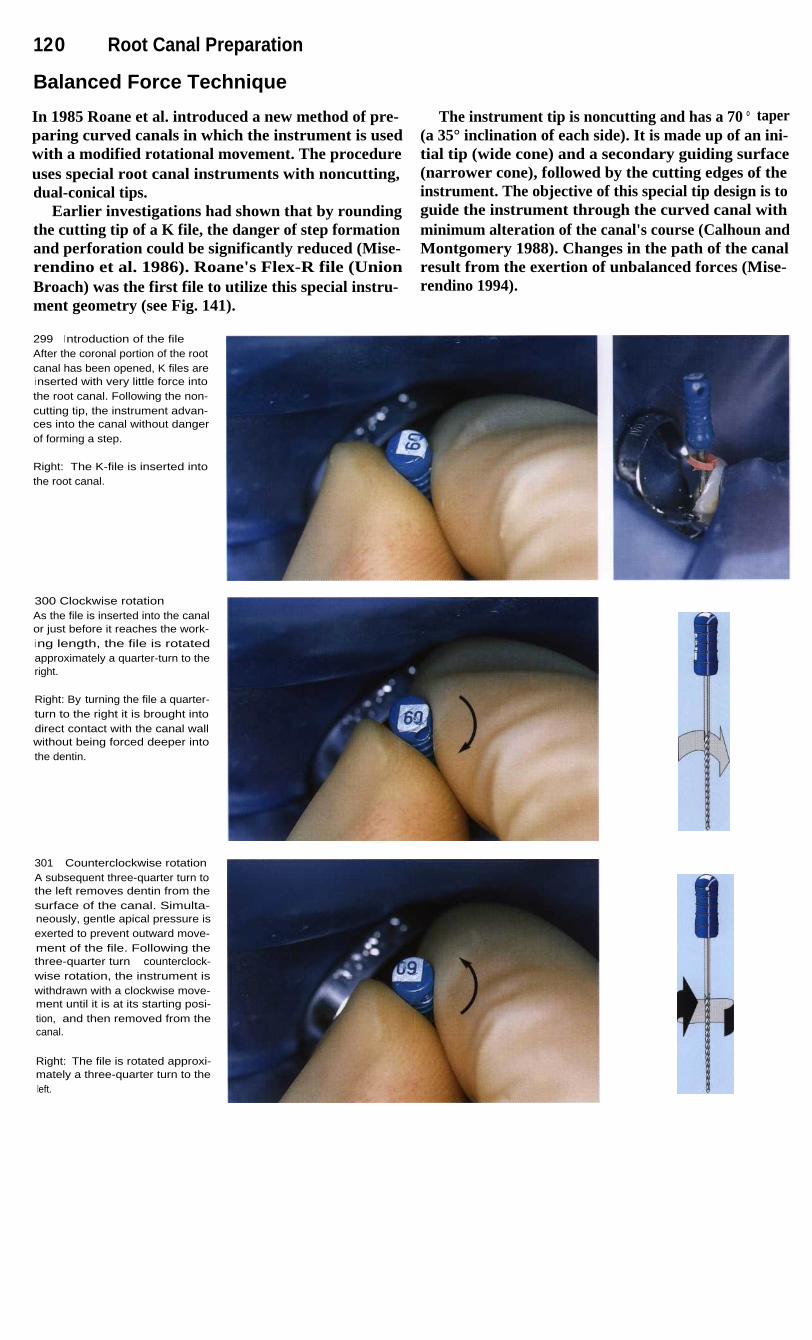
120
Root Canal Preparation
Balanced Force Technique
In 1985 Roane et al. introduced a new method of pre-paring curved canals in which the instrument is usedwith a modified rotational movement. The procedureuses special root canal instruments with noncutting,dual-conical tips.
Earlier investigations had shown that by roundingthe cutting tip of a K file, the danger of step formationand perforation could be significantly reduced (Mise-rendino et al. 1986). Roane's Flex-R file (UnionBroach) was the first file to utilize this special instru-ment geometry (see Fig. 141).
299
I ntroduction of the fileAfter the coronal portion of the rootcanal has been opened, K files arei nserted with very little force intothe root canal. Following the non-cutting tip, the instrument advan-ces into the canal without dangerof forming a step.
Right: The K-file is inserted intothe root canal.
300 Clockwise rotationAs the file is inserted into the canalor just before it reaches the work-ing length, the file is rotatedapproximately a quarter-turn to theright.
Right: By turning the file a quarter-turn to the right it is brought intodirect contact with the canal wallwithout being forced deeper intothe dentin.
301
Counterclockwise rotationA subsequent three-quarter turn tothe left removes dentin from thesurface of the canal. Simulta-neously, gentle apical pressure isexerted to prevent outward move-ment of the file. Following thethree-quarter turn counterclock-wise rotation, the instrument iswithdrawn with a clockwise move-ment until it is at its starting posi-tion, and then removed from thecanal.
Right: The file is rotated approxi-mately a three-quarter turn to theleft.
The instrument tip is noncutting and has a 70 ° taper(a 35° inclination of each side). It is made up of an ini-tial tip (wide cone) and a secondary guiding surface(narrower cone), followed by the cutting edges of theinstrument. The objective of this special tip design is toguide the instrument through the curved canal withminimum alteration of the canal's course (Calhoun andMontgomery 1988). Changes in the path of the canalresult from the exertion of unbalanced forces (Mise-rendino 1994).

Balanced Force Technique
121
With the balanced force technique, the K file is in-troduced into the canal without exerting force. Simul-taneously the instrument is rotated one-quarter turn tothe right (clockwise). This movement moves the cut-ting blades of the instrument against the dentinal wall.Next the file is given a three-quarter turn to the left(counterclockwise) while maintaining light apical pres-sure to keep the file at the same depth in the canal andprevent if from moving outward. During this turningmovement dentin is scraped from the canal wall with-out a high risk of instrument fracture. Next the dentin
shavings are picked up by half a turn clockwise and re-moved from the canal with the instrument. Using thistechnique, 80% of crooked canals up to size 40 can beprepared without altering their course (Southard et al.1987). Furthermore, significantly less dentin debris ispushed out through the apical foramen than with thestep-back technique (McKendry 1990).
302 Working lengthI nstrumentation with rotationalmovements is continued until thefull working length, previouslymeasured on a radiograph, isreached.
303 Master pointRotational instrumentation of astraight canal produces a roundcross-section, which facilitatesaccurate placement of a gutta-percha point. The length is verifiedby means of a master cone radio-graph.
304 EvalutaionA dense, homogenous root canalfilling can be seen on the imme-diate postoperative radiograph. Itwas placed by the lateral conden-sation technique.

122
Root Canal Preparation
Step-Back Technique
The demise of the silver point filling and its replace-ment by plastic, inert gutta-percha required a change inthe concept of root canal preperation. The relativelyparallel walled preparation form with very little taperwas abandoned in favor of a more conical canal form.This instrumentation technique forms an apical stopand thereby avoids irritation of the periapical tissues bymedicaments or filling material. Because there is verylittle canal enlargement and removal of dentin near theapex, the danger of perforation is reduced.
In a study by Goldman et al. (1988) the cleanlinessof root canals as well as their form and course wereevaluated following instrumentation with K files, Hed-strom files, and Unifiles. The only file that created adefinite apical stop, an almost round canal cross-section, a good apical preparation without irregularwidened areas, and a conical canal form from apex tothe cervical region was the K file used with the step-back technique. However, 46% of the curved canalsstudied showed an alteration in their course in the api-cal region (Cinnis et al. 1988).
305 Apical preparationLeft: At the beginning of instru-mentation, the length of the canaland the size of the initial apical file(I AF) are determined on a radio-graph. Notice the periapical radio-l ucency and the slight overexten-sion of the measurement file.
Right: Starting with the IAF, theroot canal is enlarged to the work-i ng length through four file sizes.
306 Step-back techniqueAfter the root canal has been en-larged throughout its entire lengthto the size of the apical master file,here size 35, the subsequent filesare each made 1 mm shorter thanthe previous file. Thus, the inser-tion length of the size 40 K file isshortened by 1 mm, size 45 by2 mm, size 50 by 3 mm, and size55 by 4 mm. The drawing clearlyshows the tapered root canal pre-paration that is formed by this pro-cedure. The steps are smoothedby the intermittent reintroductionof the AMF. This simultaneouslyprevents blockage of the apicalcanal by dentin chips and verifiesaccessibility to the apical constric-tion. K files are used exclusively inthis preparation technique.

Step-Back Technique
123
In the step-back technique, the apical portion isinstrumented first, and then the coronal portion isshaped. After the access opening is made, the workinglength is determined on a measurement radiograph.The first file that binds in the canal at the workinglength is considered the initial apical file (IAF). Theroot canal must then be enlarged by circumferentialfiling through an additional four instrument sizes.During this initial phase of preparation, no instrumentsizes may be skipped or a blockage may be created.
The last file manipulated to the working lengthshould remove only white dentin shavings, and is des-ignated the apical master file (AMF). Its size deter-mines the size of the gutta-percha master point that willbe used later. Next, the coronal portion of the root canalis instrumented in step-back fashion through four addi-tional sizes. Each subsequent larger size K file is setI mm shorter than the preceding size so that a conicalcanal configuration with a definite apical stop isformed. Frequent recapitulation with the AMF ensuresthat the canal remains patent.
307
First stepLeft: The canal is prepared to theapex with the AMF The radiographshows the corrected workingl ength.
Center: The first file after the AMFprepares the canal to a depth1 mm shorter than the AMF Thel ength is marked with a rubberstop.
Right: The radiograph shows thecorrect working length and areduction of the periapical radio-lucency after 3 months with adressing in place.
308
Final fileLeft: A size 50 K file has a workingl ength approximately 3 mm shorterthan that of the AMF
Center: The final file enlarges theroot canal to a depth 4 mm lessthan the original working length.
Right: After the conical canal formi s created, a gutta-percha point thesame size as the AMF is fitted.
309
Filling the canalLeft: The tapering shape of theroot canal permits lateral conden-sation to near the apex.
Center: By condensing multiplegutta-percha points, a biologicallyneutral obturation can be created.
Right: On the final radiograph ahomogenous, lightly tapering rootcanal filling with an apical stopcan be seen.

124
Root Canal Preparation
Step-Down Technique
Narrow, curved root canals are prepared by means ofthe coronal-apical ("crown down") instrumentationtechnique. In this method the coronal portion is enlarg-ed first, and only then is the apical region of the rootcanal prepared. An advantage of this technique overthe apical-coronal technique is that the coronal en-largement makes it possible to insert the irrigatingcanula quite deeply into the root canal. During the finalinstrumentation of the apical region necrotic pulptissue is thus loosened and flushed away with sodiumhypochlorite.
After the access preparation is made, the canal prep-aration is begun by assuring complete patency of thecanal. This is done by inserting a size 15 Hedstrom file,employing one-eighth circle rotations and only lightpressure. Next the root canal is enlarged coronally witha Gates-Glidden drill to the beginning of the canal'scurvature using the step-back technique. It is importantto coat the tip of the instruments with a lubricant (e. g.RC-Prep) in order to prevent binding within the canal.
310 PatencyOn the first radiograph themeasuring instrument has beeni nserted only into the coronal thirdbecause of the narrowness of theroot canal. Excessive force mustbe avoided.
Right: A Hedstrom (coated withRC-Prep) file has been advancedthrough gentle rotational move-ments to test the patency of thecanal.
311
Coronal enlargementLeft: The Hedstrom file hasreached the farthest extent of thepatent canal.
Center: The canal is carefullyenlarged through circumferentialfiling. There is no danger of creat-i ng a blockage during this phaseof preparation.
Right: The coronal portion of thecanal is widened with Gates drillsbefore the deep preparation iscompleted.
312 Apical preparationLeft: Widening of the coronal por-tion makes it possible to irrigatethe root canal. A prebent K file isthen advanced to the apical re-gion.
Right: The instruments must beprebent to conform to the curva-ture of the canal.

Step-Down Technique
125
Following enlargement of the coronal portion, theworking length is determined radiographically with asize 15 K file in place. If the instrument tip falls morethan 2 mm short, a second measurement radiograph ismade after further careful instrumentation. If the rootcanal is too narrow to allow the K file to be inserted tothe working length, passage to the apex must be care-fully established with a Hedstrom file also. Only thencan the size of the initial apical file be determined andthe canal enlarged by four sizes.
Apical preparation is accomplished by alternatinginstruments-first a Hedstom file is used for circum-ferential filling and this is followed by a K file (non-cutting tip) in a rotating working movement (balancedforce technique). Following this, the canal is widenedcoronally with a size 20 Hedstrom file, and finally theentire root canal is instrumented to the working lengthwith a prebent size 20 K file. If this file does not reachthe working length, under no circumstances should anyattempt be made to advance the instrument apically byrotating it.
313 Balanced forceLeft: The root canal is enlargedalong its entire length by using thebalanced force technique: first thei nstrument is introduced into thecanal with rotations to the right.Then the file is rotated to the left tocut dentin from the canal wall.
Center: A prebent K file prior toapical instrumentation.
Right: The instrument has becomeslightly straightened after beingrotated apically.
314 Creating a conical formLeft: Following preparation of theapical region, the canal is taperedby circumferential filing with Hed-strom files.
Right: Finally, the entire canal issmoothed by using the #35 AMFwith balanced force rotations.
315
Root canal fillingLeft: In order to prevent discolor-ation of the crown of the tooth byi ngredients of the root canal fillingmaterial, the filling must be re-moved to a level 2 mm below thecementoenamel junction.
Center: Follow-up evaluation ofthe composite restoration 2 yearsafter the root canal treatment.
Right: Radiograph of the treatedtooth showing slight straighteningof the canal.

12 6
Root Canal Preparation
Problem Solving during Instrumentation
Step Formation Funnel Formation
Root canal files must be prebent in order to preventstep formation or other blockage in the apical 4 mm.Inadequate working space can be a problem whenusing instruments 25 mm or more in length, or whenmouth opening is restricted. During the initial enlarge-ment, therefore, the instrument should be rotated intothe mesial canals of molars first. The notch in the stopindicates the direction of the bend and faces firsttoward the mesial, then toward the distal.
An apical funnel is the result of improper instrumenta-tion and straightening of the apical portion of the rootcanal. To avoid this, the apical end of the instrumentmust be bent even more than the curvature of the canalon the radiograph. Only by sufficiently prolongedinstrumentation with thin, flexible files can apical en-largement be avoided. Following every rotation duringthe balanced force technique the instrument must beremoved from the canal, carefully cleaned, and rebent.
316 Working lengthSize 15 files that were not prebentare inserted into the three rootcanals of the maxillary first molarto determine the working lengths.The curvature of the canals isnoted at the same time.
317 Prebending the instru-mentsLeft: The apical segment of eachi nstrument is bent more sharplythan the curvature of the canal,and the direction of the bend ismarked by the point of the stop,which initially points toward themesial.
Center: I nsertion of the instrument.
Right: The instrument is insertedi nto the mesiobuccal canal with itscurvature opposite that of thecanal.
318
Rotation of the instrumenti nto the canalLeft: The file is rotated as it is ad-vanced farther into the root canalwith almost no force. The point ofthe silicone stop indicates theamount of rotation.
Center: The K file was able to berotated into the root canal to theworking length with no problem.The point on the stop now facesdistally.
Right: Rotation of the instrumentby 180°.

Problem Solving during Instrumentation 127
Perforation Overinstrumentation
Excessive initial enlargement of the mesial canal of amolar can lead to penetration of the canal wall. Thepath of the root canal must be carefully evaluated onthe diagnostic radiograph before the decision to useGates-Glidden drills is made. Hedstrom files up to size25 can be used just as well for the initial enlargementof the canal. Excessive removal of dentin can be avoid-ed by filing toward the curvature of the canal.
Enlargement of the apical constriction can result inpostendodontic reactions. This danger can be reducedby accurate radiographic determination of the lengthwith identification of the correct apical reference point,which can be different for every root canal.
Additional radiographs make it possible to correctchanges in the canal length brought about by thestraightening of curved sections of the canal.
319 Canal instrumentationThe curved root canals have beencompletely prepared by this instru-mentation technique.
Left: Shaping of the coronal regionand tapering of the canals bymeans of flexible Hedstrom files.
320
Root canal fillingThe three canals are filled withgutta-percha to the apical refer-ence point by means of the lateralcondensation technique. Nostraightening of the paths of thecanals has occurred.
321
Radiographic follow-upAn examination 2 years aftercompletion of the endodontic andrestorative treatment revealsnothing unusual. There are nosigns of pathologic changes andthe patient is free of discomfort.

128
Root Canal Preparation
Surface of the Canal Wall Following Hand Instrumentation
During hand instrumentation of the root canal withhand instruments, dentin and pulp-tissue fragments aremacerated and most of these are removed from the rootcanal by the instruments and by irrigation. Some rem-nants, however, do remain on the surface of the canaland can be pressed against the canal wall and into theadjacent dentinal tubules. The adhesion of this smearlayer on the underlying dentin is not especially pro-nounced (Kockapan 1995).
This 2-5-pm-thick superficial deposit consists of amixture of ground and fragmented dentin and pre-dentin and, if canal enlargement is inadequate, somebacterially infected necrotic pulp tissue (McComb etal. 1976). In the SEM the surface of the canal appearsrelatively smooth. The dentin tubules are covered withdeposits of abraded dentin. The coarse dentin particles(smear plugs) can be demonstrated as deep as 40 gmwithin the tubules (Mader et al. 1984).
322 Root canal afterextirpationA After extirpation of the pulp and
before instrumentation almostall soft tissue has been re-moved from the root canal sur-face. A uniform covering of thecanal wall with residual pulptissue can be seen.
B At higher magnification pulp-tissue fragments, which havebeen torn from the canal wall,and partially opened dentinaltubules are visible.
C The residual tissue holds odon-toblastic processes that havebeen torn away and may bei nfected with bacteria.
(SEM images)
323 Root canal after instru-mentation with Hedstrom filesA In its middle portion the root
canal is smooth and free of re-sidual pulp tissue, althoughthere are large longitudinalgrooves resulting from nonuni-form circumferential filing.
B The dentin of the canal wall hasbeen smoothed. A smear layerpartially covers the orifices ofthe dentinal tubules, althoughuncovered sections are alsopresent.
C At higher magnification the en-trances to the dentinal tubulesare visible. The canal has beeni rrigated with sodium hypochlo-rite solution during instrumenta-tion.
( SEM image)

Surface of t he Canal Wall Following Hand Instrumentation 129
Following pulp extirpation alone, larger pulp-tissueremnants are found on the surface of the root canalwith individual pieces of tissue torn loose from the un-derlying dentin. Instrumentation of straight root canalswith Hedstrom files produces a surface that is free oflarger tissue remnants, but the canal walls exhibit lon-gitudinal grooves. The middle third of the canal isclean with partially opened dentinal tubules. Only rota-tional instrumentation with reamers leads to a smoothsurface with no large dentinal fragments (Beer andGangler 1989). Straight root canals can be fully pre-
pared and filled at the same sitting, irrespective of themethod of instrumentation used. Approximately 80%of curved canals can be cleaned well over their entirelengths with either Hedstrom files or K files (Haikeland Alleman 1988). Regardless of which technique isused, curved canals can be only incompletely cleansedof infected pulp-tissue remnants. The anatomy of theroot canal has a greater influence on the effectivenessof canal preparation than does the specific method ofpreparation (Langeland et al. 1985).
324 Instrumentation withrat-tail files
A The surface of the prepared
root canal appears roughened.I rregularities and l ongitudinal
grooves are visible.
B The dentin is fissured and torn.
There is no regular smear layer
visible.
C At higher magnification dentinflakes of various sizes can be
seen loosely covering the den-
tin. The entrances to the dentin-al tubules, however, are wide
open and not plugged with den-tin shavings.
(SEM image)
325 Instrumentation with
K filesA After rotational instrumentation
using the balanced force tech-
nique the apical region of theroot canal is likewise smooth
and free of residual tissue. A
lateral canal is occluded withdentin shavings.
B The surface of the canal is uni-formly covered by a smear layer
as the result of direct contact bythe instruments.
C At higher magnification theclean canal surface is visible
with complete closure of the
dentinal tubules.
(SEM image)

130
Root Canal Preparation
I nstrumentation under the Surgical Microscope
There is a limit to our ability to make ever finer detailsmore visible simply by bringing the observed objectcloser to the eye. When the object comes too close tothe eye it no longer appears sharp because of the limit-ed ability of the eye to accommodate. Adults with nor-mal vision can still perceive objects sharply if they areat least 10 cm away from the eye, but fatigue occursrapidly at this distance. Only when the distance isincreased to 25 cm can the object be seen clearly forlonger periods of time without special effort. Thisdistance is referred to as the conventional visual dis-
tance (Gerlach 1985). At this distance an observer candistinguish two points equally if they are at least 0.15mm from one another, which corresponds to a visualangle of 2 minutes of angle. In a microscope the lightfrom the object being viewed passes through the objec-tive lens and its image is projected toward infinity. Thelens inside the tube projects an intermediate image tothe ocular lens in the eyepiece, which presents the en-larged image to the eye. The resulting visual angle isnow much larger so that much smaller details can berecognized (Kapitza 1994).
326 TrepanationLeft: The patient experiencedacute symptoms from the mandib-ular left canine following cementa-tion of an extensive fixed prosthe-sis.
Center: An access opening ismade and enlarged through thecrown.
Right: The working-length radio-graph taken at a slightly eccentricangle suggests a second rootcanal.
327 Access preparationLeft: With a 20x magnifying surgi-cal microscope, the entrance to asecond canal can be seen lingualto the first instrumented canal.
Right: At 25x magnification thesecond canal entrance can beeasily located.
328 Length determinationLeft: After the length from the firstradiograph is adjusted, the filereaches the apical constriction. Toavoid overlapping, the two canalscan be measured separately.
Center: Two different types of filesare inserted into the root canals.
Right: The course of the two in-struments reveals that there aretwo separate canals with two sepa-rate foramina.

I nstrumentation under the Surgical Microscope
In 1894, Greenough recommended the use of twoseparate tubes, each fitted with an objective and anocular and inclined toward one another at an angle of14°-16° so that the object could be viewed with botheyes simultaneously. This angle corresponds to theconvergence angle of the eyes when accommodated toan object at a distance of 25 cm. To ensure that theimage will not appear reversed in either its vertical orhorizontal orientation, an image-erecting Porro prismis incorporated between the objective and ocular lenses(Czapski and Gebhard 1897).
Stereoscopic vision with the surgical microscope isbased upon the fact that because of the distance be-tween the eyes, the viewing angle is different for eacheye, and therefore the two retinal images are not quiteidentical. Only in the brain are they processed into onesingle overall impression that produces a three-dimen-sional representation of the object. The stereoscopiceffect is possible only if the object viewed is within thearea of sharp focus (depth of field), which is shallowerat higher magnifications. Therefore, the surgical micro-scope is used only at lower magnifications.
329 Deep preparationLeft: Preparation under a micro-scope begins with enlargement ofthe canal with Hedstrom filesunder 10-16x magnification.
Center: To help open the rootcanals a lubricant containing EDTAis placed on the tip of the file.
Right: After progressive enlarge-ment, the canal is instrumentedwith the final AMF.
330 Use of a microscopeLeft: Between changes of files thefloor of the cavity is checked with1 6-25x magnification. Because ofthe better overall view, instrumen-tation should be carried out underlower magnification.
Right: The two root canals areconnected by an isthmus that stillcontains tissue fragments. Thesecond canal is now completelyi nstrumented also.
331
Root canal obturationLeft: With the absence of clinicalsymptoms at the second appoint-ment, the gutta-percha points arefitted.
Center: The two master points areplaced into the canals up to thei ndentations that mark the workingl engths.
Right: The canals are filled usingthe lateral condensation techniqueand a final radiograph is taken thatshows a precise apical fit.
131
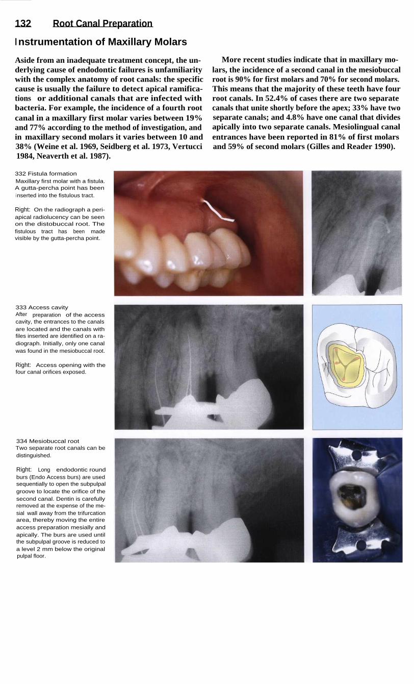
132
Root Canal Preparation
I nstrumentation of Maxillary Molars
Aside from an inadequate treatment concept, the un-derlying cause of endodontic failures is unfamiliaritywith the complex anatomy of root canals: the specificcause is usually the failure to detect apical ramifica-tions or additional canals that are infected withbacteria. For example, the incidence of a fourth rootcanal in a maxillary first molar varies between 19%and 77% according to the method of investigation, andin maxillary second molars it varies between 10 and38% (Weine et al. 1969, Seidberg et al. 1973, Vertucci1984, Neaverth et al. 1987).
More recent studies indicate that in maxillary mo-lars, the incidence of a second canal in the mesiobuccalroot is 90% for first molars and 70% for second molars.This means that the majority of these teeth have fourroot canals. In 52.4% of cases there are two separatecanals that unite shortly before the apex; 33% have twoseparate canals; and 4.8% have one canal that dividesapically into two separate canals. Mesiolingual canalentrances have been reported in 81% of first molarsand 59% of second molars (Gilles and Reader 1990).
332 Fistula formationMaxillary first molar with a fistula.A gutta-percha point has beeni nserted into the fistulous tract.
Right: On the radiograph a peri-apical radiolucency can be seenon the distobuccal root. Thefistulous tract has been madevisible by the gutta-percha point.
333 Access cavityAfter preparation of the accesscavity, the entrances to the canalsare located and the canals withfiles inserted are identified on a ra-diograph. Initially, only one canalwas found in the mesiobuccal root.
Right: Access opening with thefour canal orifices exposed.
334 Mesiobuccal rootTwo separate root canals can bedistinguished.
Right: Long endodontic roundburs (Endo Access burs) are usedsequentially to open the subpulpalgroove to locate the orifice of thesecond canal. Dentin is carefullyremoved at the expense of the me-sial wall away from the trifurcationarea, thereby moving the entireaccess preparation mesially andapically. The burs are used untilthe subpulpal groove is reduced toa level 2 mm below the originalpulpal floor.
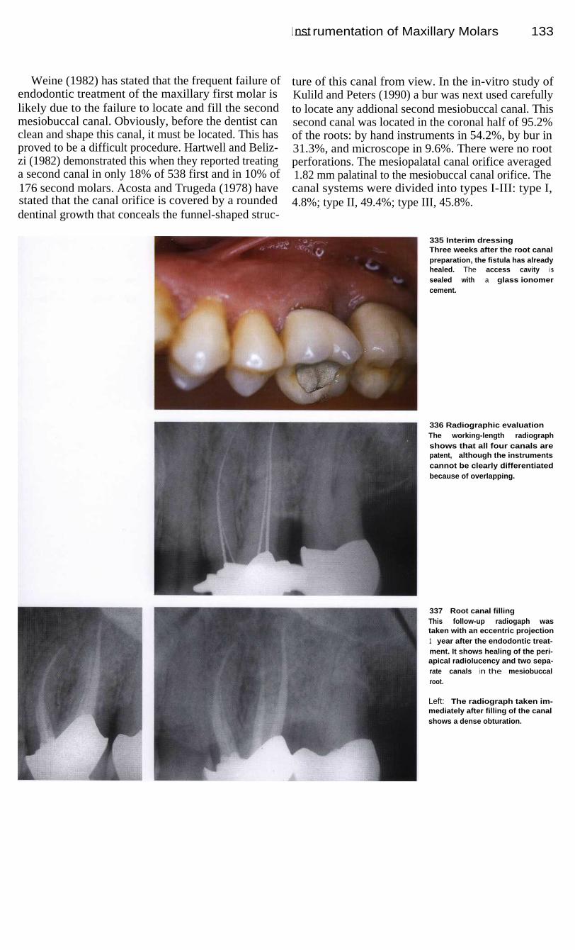
I nst rumentation of Maxillary Molars
133
Weine (1982) has stated that the frequent failure ofendodontic treatment of the maxillary first molar islikely due to the failure to locate and fill the secondmesiobuccal canal. Obviously, before the dentist canclean and shape this canal, it must be located. This hasproved to be a difficult procedure. Hartwell and Beliz-zi (1982) demonstrated this when they reported treatinga second canal in only 18% of 538 first and in 10% of176 second molars. Acosta and Trugeda (1978) havestated that the canal orifice is covered by a roundeddentinal growth that conceals the funnel-shaped struc-
ture of this canal from view. In the in-vitro study ofKulild and Peters (1990) a bur was next used carefullyto locate any addional second mesiobuccal canal. Thissecond canal was located in the coronal half of 95.2%of the roots: by hand instruments in 54.2%, by bur in31.3%, and microscope in 9.6%. There were no rootperforations. The mesiopalatal canal orifice averaged1.82 mm palatinal to the mesiobuccal canal orifice. Thecanal systems were divided into types I-III: type I,4.8%; type II, 49.4%; type III, 45.8%.
335 Interim dressingThree weeks after the root canalpreparation, the fistula has alreadyhealed. The access cavity i ssealed with a glass ionomercement.
336 Radiographic evaluationThe working-length radiographshows that all four canals arepatent, although the instrumentscannot be clearly differentiatedbecause of overlapping.
337
Root canal fillingThis follow-up radiogaph wastaken with an eccentric projection1 year after the endodontic treat-ment. It shows healing of the peri-apical radiolucency and two sepa-rate canals in the mesiobuccalroot.
Left: The radiograph taken im-mediately after filling of the canalshows a dense obturation.

134
Root Canal Preparation
Engine-Driven Canal Instrumentation
As early as 1899 a needle-shaped root canal drill drivenby a dental motor was developed by Rollins to facili-tate the fatiguing, time-consuming task of root canalinstrumentation for the dentist. In order to minimizeinstrument fracture, the rotational speed was laterlimited to 100 rpm. However, it was not until the intro-duction of the Racer file handle in 1958 and the Giro-matic handpiece in the year 1964 that the epoch ofengine-driven root canal instrumentation began in ear-nest (Hulsmann 1993 a).
The Racer file handle allows the intrument to make
a piston-like movement. The Giromatic handpiece pro-duces reciprocating one-quarter turns and has been imi-tated by many other handpieces. The Intra-Endo 3LDutilizes alternating 80° rotations. The Endolift 1, in ad-diton to making reciprocating quarter turns, also pro-duces vertical strokes. The primary movement of theCanalfinder system is a vertical stroke with an ampli-tude that depends upon the rotational speed and theresistance offered by the canal. In the Excalibur hand-piece, the files execute multilateral movements, or so-called aleatoric oscillations.
338 Beginning situationDiagnostic radiograph of a maxil-lary molar with distally curving rootcanals. Ideally, engine-driven in-strumentation should produce uni-formly tapered canals without en-larging the apical foramen, and atthe same time prepare apicalstops. The canal walls should becompletely cleansed of all residualnecrotic tissue.
339 Working lengthAfter the access cavity has beenprepared, the working lengths ofthe root canals are determinedwith the help of radiographs.Because of the tendency of allengine-driven aids to straightencurved root canals, sometimes to agreat extent, the working lengthsmay become shortened.
340 Mode of operationThe mode of operation of the Giro-matic and Endolift 2 instruments isa reciprocating quarter-turn move-ment. In the latter system, regularhand instruments can be latchedonto the handpiece.
Right: During clinical use theworking length must be maintainedwith a stop. The instruments areprebent and must be frequentlychecked for surface integrity.
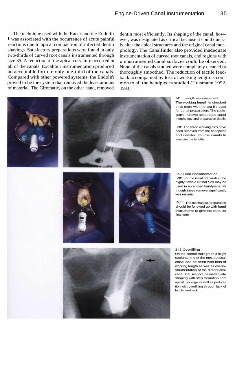
Engine-Driven Canal Instrumentation 135
The technique used with the Racer and the EndoliftI was associated with the occurrence of acute painfulreactions due to apical compaction of infected dentinshavings. Satisfactory preparations were found in onlytwo-thirds of curved root canals instrumented throughsize 35. A reduction of the apical curvature occurred inall of the canals. Excalibur instrumentation producedan acceptable form in only one-third of the canals.Compared with other powered systems, the Endoliftproved to be the system that removed the least amountof material. The Giromatic, on the other hand, removed
dentin most efficiently. Its shaping of the canal, how-ever, was designated as critical because it could quick-ly alter the apical structures and the original canal mor-phology. The Canalfinder also provided inadequateinstrumentation of curved root canals, and regions withuninstrumented canal surfaces could be observed.None of the canals studied were completely cleaned orthoroughly smoothed. The reduction of tactile feed-back accompanied by loss of working length is com-mon to all the handpieces studied (Hulsmann 1992,1993).
341 Length reassessmentThe working length is checkedonce more with the last file usedfor canal preparation. The radio-graph shows acceptable canalmorphology and preparation depth.
Left: The three working files havebeen removed from the handpieceand inserted into the canals toevaluate the lengths.
342 Final instrumentationLeft: For the initial preparation thehighly flexible Nitinol files may beused in an angled handpiece, al-though these remove significantlyl ess material.
Right: The mechanical preparationshould be followed up with handi nstruments to give the canal itsfinal form.
343 OverfillingOn the control radiograph a slightstraightening of the mesiobuccalcanal can be seen with loss ofworking length as well as overin-strumentation of the distobuccalcanal. Causes include inadequateshaping with step formation andapical blockage as well as perfora-tion with overfilling through lack oftactile feedback.

136
Root Canal Preparation
Instrumentation with Profile
A new generation of instruments has been developedfrom nickel-titanium that potentially allow shaping ofnarrow and curved canals. Himel et al. (1995) evaluat-ed Ni-Ti hand files using dental students to preparecurved canals. These preparations were rated higherthan preparations using stainless steel files with signifi-cantly less zipping and ledging. Ni-Ti instruments withincreased taper have been developed in the hope thatgreater flare along the shaft would automatically createthe flare required in the canal shape. The taper of theseinstruments (0.04 mm/mm) is twice that of convention-
al instruments that have a taper of 0.02 mm/mm. The in-crease in taper, when used in a modified crown-downtechnique, allows the smaller files to function underreduced stress and higher tactile sensation at workinglength. The Profiles (Tulsa-Dentsply) are made bygrinding three equally spaced, U-shaped groovesaround the Ni-Ti shaft. The instruments have flutes withflat outer edges, known as radial lands, which cut witha planing action. The Profile 04 Series 29 has a novelrange of sizes including a series that increases in dia-meter by a consistent 29% (Wolcott and Himel 1997).
344 Diagnostic radiographThe maxillary first molar has anecrotic pulp, but no visible peri-apical radiolucency. The patientreported continuous pain that in-creased in the evenings. The rootcanals are slightly curved and bothbuccal roots are shorter than thepalatal root.
345 Coronal enlargementLeft: First the coronal portions ofthe canals are enlarged with aOrifice shaper, followed by Profile06 and than by Profile 04 withoutreaching the working lengths.
Right: The canals are furtherwidened with the Profile 04 andi rrigated with sodium hypochloritesolution.
346 Gates-Glidden drillsLeft: The coronal portions of thecanals are given a conical shapewith Gates-Glidden drills, sizes 1through 4.
Right: Shaping with Gates-Gliddendrills is necessary only if thecanals are to be obturated byusing lateral or vertical condensa-tion techniques. If a Thermafilfilling is to be placed, these drillsneed not be used.

I nstrumentation with Profile
137
The type of root canal instrumentation used with theProfile system varies depending upon the filling tech-nique to be used later. If the canals are to be filled bythe Thermafil technique, instrumentation is startedwith a size Orifice shaper, preparing only the straightportion. The files rotate at speeds of 350 rpm. If thefirst file reaches this length and rotates freely in thecanal, a Profile 06 is inserted to the same workinglength. A profile 04 is then used in the apical segmentof the canal. Only then is the size 2 Profile inserted tothe entire working length. Apical enlargement is ac-
complished with Profile instruments of sizes 3 through7. No further coronal enlargement is performed. If, onthe other hand, the canal is to be filled by lateral con-densation, Gates-Glidden drills are used again as in thestep-down technique to form a more strongly taperedpreparation. Rotary Ni-Ti Profiles provide a more cen-tered preparation with less apical transportation thanhand files (Cotti et al. 1998). Even students with no en-dodontic experience can easily learn to use Profile withsuccess and achieve good root canal geometry (Bau-mann and Roth 1999).
347 CleaningLeft: I nstrumentation at a secondsitting following emergency treat-ment with the Profile 04.
Right: Apical enlargement by threeto four sizes and the beginning ofconical shaping with the Profile 06.
348 ShapingLeft: For lateral condensation theroot canals are tapered further withGates-Glidden drills.
Right: Each canal is tapered withGates-Glidden drills using wipingmovements from the midcanal re-gion outward. This will facilitate thel ater condensation of gutta-perchapoints.
349 Radiographic evaluationRadiograph of the completed rootcanal filling showing well-formedcanals and no periapical abnor-malities.

138
Root Canal Preparation
I nstrumentation with Tri Auto ZX
In an effort to obtain complete debridement of a rootcanal system, debris such as dentinal filings, necroticpulp tissue, bacteria, or irrigants may be extruded intoperiradicular tissue. This debris may lead to postopera-tive pain and discomfort. Hand or engine-driven in-strumentation with Ni-Ti files that uses rotation seemsto reduce significantly the amount of debris extrudedapically when compared with a push-pull (filing) tech-nique (Reddy and Hicks, 1998). Significantly more de-bris was extruded when filing was performed up to theapical foramen, irrespective of the technique used
(Beeson et al. 1998). Safety features include AutoApical Reverse (AAR) to prevent overinstrumentation.In a study, 60 extracted teeth were instrumented. Onaverage, the electronic length was 0.54 mm shorterthan the actual length, and the instrumented length wasshorter than the electronic length. Instrumentation toAAR level 1.0 consistently approximated and fre-quently violated the apical constriction, without conse-quent extrusion of vertically condensed gutta-percha(Campbell et al. 1997).
350 Clinical situationThe diagnostic radiograph of amaxillary second molar with pene-trating secondary caries revealscurved mesiobuccal and distobuc-cal root canals. The tooth is verypainful but does not yet react topercussion.
351 Access OpeningThe inlay is removed and the ca-ries excavated under anesthesia,exposing the pulp.
Right: Following preparation of theaccess cavity and extirpation of thepulp tissue, patency of the canalsi s established.
352 Tri Auto ZXThis low-speed handpiece, com-bined with the technology of theRoot ZX, gives the clinician thecapability to electronically monitorthe root canal before, during, andafter instrumentation.
Right: The Tri Auto ZX has threefunctions: automatic start/stop (1),automatic torque reverse (2), andautomatic apical reverse (AAR) (3).The handpiece stops and reversesthe rotation of the file when the tipreaches the apex or when toomuch pressure is applied.

I nstrumentation with Tri Auto ZX
139
Ni-Ti endodontic instruments were introduced tofacilitate instrumentation of curved canals. Despitetheir increased flexibility, separation is still a concernwith Ni-Ti instruments, and they have been reported toundergo unexpected fracture. Separation can occurwithout any visible signs of previous permanent defor-mation, apparently by forces within the elastic limit ofthe instrument (Pruett et al. 1997). In a study byRowan et al. (1996), Ni-Ti files with 0.02 taper fractu-red significantly earlier than comparable steel files.Wolcott and Himel (1997), however, demonstrated a
higher load strength for Ni-Ti instruments with a 0.04taper than for instruments of the same material with0.02 taper. Therefore, a second safety feature of the TriAuto ZX handpiece is the inclusion of an automatictorque reversal to prevent file breakage. Canal instru-mentation with a handpiece setting of 1.0 consistentlyallowed approximation of the apical constriction with-out file breakage or canal transportation (Campbell &Friedman 1997). Breakage of Ni-Ti files is less likelyif the file is run at the lowest recommended speed(Dietz et al. 1998).
353 Engine-powered canalenlargementRadiographic evaluation for paten-cy of the root canals. There isdistinct bending of the measuringfiles near the apices.
Left: The initial mechanical enlar-gement with Gates-Glidden drills isfollowed by apical instrumentation.
354 Master pointAfter preparation of the curved rootcanals with a combination of steeland Nitinol files and before obtura-tion of the canals, the preparationis evaluated with gutta-perchapoints inserted.
Left: Visual evaluation of the result-i ng preparation.
355 FillingAfter the root canal filling has beenplaced the results of the treatmentare checked with a radiograph.

140
Root Canal Preparation
Instrumentation with the Quantec Series 2000
The Quantec Series 2000 uses Ni-Ti instruments ofgraduating tapers. The Quantec instrument incorpo-rates many new design configurations including a moreideal cutting angle of the blade, flutes designed to helpremove the dentin debris as it is being formed, wide ra-dial lands to prevent crack formation in the instrumentand help deflect the instrument around curvatures,asymmetry of the cutting surfaces to help maintain theintegrity of the central axis of the canal, and, finally, afaceted cutting tip to help prepare narrow, curved, cal-cified canals. The Quantec instruments prepare the root
canal in three stages. The Quantec #1, a 17-mm-longsize 25 instrument with a 0.06 taper, is used as an ori-fice opener. The Quantec #2, a size 15 instrument witha 0.02 taper, is used to estimate the working length. Inthe second stage, the apical seat is enlarged to a size 25.The Quantec #5, a 0.03-tapered size 25 instrument, isused to merge the coronal and apical preparation in thebeginning of the third stage. The Quantec #8, a 0.06-tapered size 25 instrument completes the flaring of thecanal.
356 Pretreatment situationThe diagnostic radiograph of thelower right first and second molarsreveals penetrating secondary car-ies and a periapical radiolucencyon the second molar. The firstmolar already shows probablesigns of inflammation from thesecondary caries under the deepfilling.
Right: The Quantec # 1, a 17-mm-l ong instrument with a 0.06 taper,i s used to open the orifices.
357 Working lengthAfter preparation of the accesscavity, the working lengths of thecanals in the first molar are deter-mined with a radiograph. Thesecond molar has already beenendodontically treated, and rege-neration of the periapical radio-l ucency is clearly evident.
Right: Three files with stoppers arei nserted into the canals.
358 Apical enlargementLeft: The Quantec 2 and 3 (# 20), a0.02 tapered # 15 file, is carried tothe estimated working length.
Middle: Quantec 4 (#25) instru-ment is then taken to the full work-i ng length.
Right: The Quantec 5, a 0.03 ta-pered #25 instrument, is used tomerge the different regions of thepreparation.

I nstrumentation with the Quantec Series 2000
Quantec instruments yielded higher centering ratiosat the apical level. There were no differences in the di-rection of canal transportation. Canal preparation timewas the shortest for Profile, followed by Fley-R files inthe Endo Gripper, the Quantec system, and ShapingHedstrom files in the M 4 handpiece (Kosa et al. 1998).The SEM examination of the internal surface of theprepared root canal showed a smooth internal surfaceafter hand preparation with Flexofile but with scratchesin the axial direction. Quantec instrumentation showedsmoother and straight cutting surfaces with no axial
scratching. Quantec instruments were effective in theremoval of major amounts of tissue from the root canalbut this removal was incomplete (Jeong-along et al.1998). The purpose of the study by Uemura et al.(1998) was to quantify the amount of remaining obtu-ration material on the canal walls, extruded debris, andthe retreatment time when Quantec, K files, and Hed-strom files were used. The Hedstrom file group requi-red less time; the automated devices did not prove to bebetter than hand instrumentation techniques.
359 ShapingLeft: During the first phase of api-cal instrumentation the canal is en-l arged from size 15 to size 25 allthe way to the working length.
Right: I n the second phase of api-cal preparation the root canal isflared with instruments that are allsize 25 but of progressively incre-asing taper (0.03, 0.04, 0.05, and0.06). Finally, the last two 0.02tapered instruments (#40 and#45) can be used in step-backfashion for further enlargement.
360 EvaluationThe depth of the preparation isevaluated on the master pointradiograph.
361
Root canal fillingThe final radiograph of the com-pleted endodontic treatment re-veals well-formed root canals.
141

142
Root Canal Preparation
I nstrumentation with Lightspeed
In 1989 Wildey and Senia introduced a new instru-ment, the Canal Master, which has a noncutting tip, avery short cutting blade, and a constant-diameter flex-ible shaft. This instrument was reported to producerounder canal preparations, cause less transportation,remain more centered, and show less apical extrusion ofdentin debris (Leseberg and Montgomery 1991, Myers& Montgomery 1991). However, these stainless-steelinstruments were disposed to rapid wear and breakage(Zuolo et al. 1992, Massa et al. 1992). A more recentchange in the Canal Master design was made possible
by the introduction of nickel-titanium. This alloy led tothe development of Lightspeed with good flexibility. Arecent study showed that Lightspeed instrumentationwas faster than hand instrumentation and also produceda better quality of root canal preparation (Closson et al.1996). In the study of Ramirez-Salomon (1997), six in-struments separated during treatment. Five of themwere bypassed and treatment was completed. Cycles tofailure significantly decreases as the radius of curvatu-re decreases from 5 mm to 2 mm and as the angle ofcurvature increases beyond 30° (Pruett et al. 1997).
362 Diagnostic radiographA maxillary premolar with a directpulp cap that failed, resulting inpersistent pain. The root canal isslightly curved to the distal. Thereis no sign of periapical radiolu-cency.
363 Coronal enlargementLeft: First the patency of the rootcanal is established with a size 15K file. Next a # 1 Gates-Gliddendrill is used to enlarge the canal toits middle third.
Center: Progressively l argerGates-Glidden drills are inserted,each 1 mm shallower than theprevious one, in the step-backtechnique.
Right: Crown-down preparationwith Gates-Glidden drills.
364 Length determinationLength determination on a radio-graph following coronal enlarge-ment. Preflaring of the coronal por-tion enables precise determinationof the working length and preventsbinding of the files in the canal. Italso facilitates irrigation of thedeepest parts of the canal.
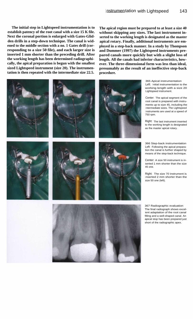
I nstrumentation with Lightspeed
143
The initial step in Lightspeed instrumentation is toestablish patency of the root canal with a size 15 K file.Next the coronal portion is enlarged with Gates-Glid-den drills in a step-down technique. The canal is wid-ened to the middle section with a no. 1 Gates drill (cor-responding to a size 50 file), and each larger size isinserted 1 mm shorter than the preceding drill. Afterthe working length has been determined radiographi-cally, the apical preparation is begun with the smallestsized Lightspeed instrument (size 20). The instrumen-tation is then repeated with the intermediate size 22.5.
The apical region must be prepared to at least a size 40without skipping any sizes. The last instrument in-serted to the working length is designated as the masterapical rotary. Finally, additional instruments are em-ployed in a step-back manner. In a study by Thompsonand Dummer (1997) the Lightspeed instruments pre-pared canals more quickly but with a slight loss oflength. All the canals had inferior characteristics, how-ever. The three-dimensional form was less than ideal,presumably as the result of an ineffective step-backprocedure.
365 Apical instrumentationLeft: I nitial instrumentation to theworking length with a size 20Lightspeed instrument.
Center: The apical segment of theroot canal is prepared with instru-ments up to size 45, including thei ntermediate sizes. The Lightspeedi nstruments are used at a speed of750 rpm.
Right: The last instrument insertedto the working length is designatedas the master apical rotary.
366 Step-back instrumentationLeft: Following the apical prepara-tion the canal is further shaped bymeans of the step-back technique.
Center: A size 50 instrument is in-serted 1 mm shorter than the size45 one.
Right: The size 70 instrument isi nserted 2 mm shorter than thesize 50 one (left).
367 Radiographic evaluationThe final radiograph shows excel-lent adaptation of the root canalfilling and a well-shaped canal. Anapical stop has been prepared justshort of the radiographic apex.
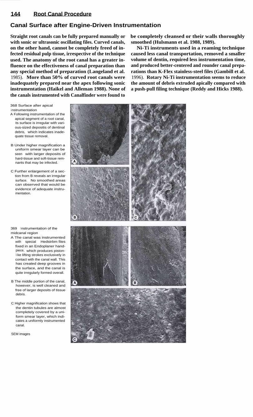
144
Root Canal Procedure
Canal Surface after Engine-Driven Instrumentation
Straight root canals can be fully prepared manually orwith sonic or ultrasonic oscillating files. Curved canals,on the other hand, cannot be completely freed of in-fected residual pulp tissue, irrespective of the techniqueused. The anatomy of the root canal has a greater in-fluence on the effectiveness of canal preparation thanany special method of preparation (Langeland et al.1985). More than 50% of curved root canals wereinadequately prepared near the apex following sonicinstrumentation (Haikel and Alleman 1988). None ofthe canals instrumented with Canalfinder were found to
be completely cleansed or their walls thoroughlysmoothed (Hulsmann et al. 1988, 1989).
Ni-Ti instruments used in a reaming techniquecaused less canal transportation, removed a smallervolume of dentin, required less instrumentation time,and produced better-centered and rounder canal prepa-rations than K-Flex stainless-steel files (Gambill et al.1996). Rotary Ni-Ti instrumentation seems to reducethe amount of debris extruded apically compared witha push-pull filing technique (Reddy and Hicks 1988).
368 Surface after apicali nstrumentationA Following instrumentation of the
apical segment of a root canal,its surface is irregular with vari-ous-sized depositis of dentinaldebris, which indicates inade-quate tissue removal.
B Under higher magnification auniform smear layer can beseen with larger deposits ofhard-tissue and soft-tissue rem-nants that may be infected.
C Further enlargement of a sec-tion from B reveals an irregularsurface. No smoothed areascan observed that would beevidence of adequate instru-mentation.
369
I nstrumentation of themidcanal regionA The canal was instrumented
with special Hedstrbm filesfixed in an Endoplaner hand-piece, which produces piston-l i ke lifting strokes exclusively incontact with the canal wall. Thishas created deep grooves inthe surface, and the canal isquite irregularly formed overall.
B The middle portion of the canal,however, is well cleaned andfree of larger deposits of tissuedebris.
C Higher magnification shows thatthe dentin tubules are almostcompletely covered by a uni-form smear layer, which indi-cates a uniformly instrumentedcanal.
SEM images

145
Disinfection
Bacteria can still be present in the root canal after intrumentation is completed, and can beresponsible for the return of painful symptoms. The use of antibiotics cannot compensate for in-adequate instrumentation or failure to employ appropriate disinfectants. Medications appliedthrough the root canal should eliminate all remaining bacteria, reduce the periapical inflamma-tion, and stimulate bone repair. The dressing must serve as a barrier in case there is coronalleakage, combat embedded microorganisms, and prevent the entry of apical secretions into theinstrumented root canal (Chong and Pitt Ford 1992).
If the root canal is not filled with a disinfecting dressing between appointments, bacteria canmultiply and approach the numbers present at the beginning of the root canal treatment (Bystromand Sundqvist 1981). In clinical practice it is recommended either that an interim dressingcontaining an antibacterial agent be placed (Bystrom et al. 1985), or that the root canal beobturated at the first appointment in order to deprive the microorganisms of nutrients and spaceto multiply (Soltanoff 1978, Oliet 1983).
It is true that the localized application of a corticosteroid (e.g. Ledermix) will eliminateclinical symptoms, but at the same time, it reduces the overall regenerative ability. Corticosteroidsreduce all stages of inflammation, but they likewise inhibit the transformation of fibroblasts andthe production of antibodies. Because inflammation is not primarily a pathologic state, but rathera useful defense reaction of tissue, a corticosteroid dressing does not treat the cause of the prob-lem (Raab 1993).
The interim dressing should also loosen remnants of tissue that could not be reached during thefirst appointment. Two studies (Turek and Langeland 1982, Langeland et al. 1985) reportedfailure to achieve totally clean dentin surfaces in root canals that were crooked, partiallyobliterated, or altered by resorption, regardless of the method of instrumentation used. Not onlynecrotic tissue cells but also bacteria or their metabolic byproducts can be found within dentinaltubules and pulp-tissue remnants. Therefore, in addition to their antimicrobial effect, disinfectantirrigating solutions and interim dressings have as their objective the loosening and removal ofremaining areas of soft tissue (Spangberg et al. 1973, Barnett et al. 1985).
Because medications can diffuse into the pulp tissue or be transported through the apicalforamen during root canal instrumentation, strong antimicrobial agents can cause considerablepostendodontic problems (Walton and Langland 1978).
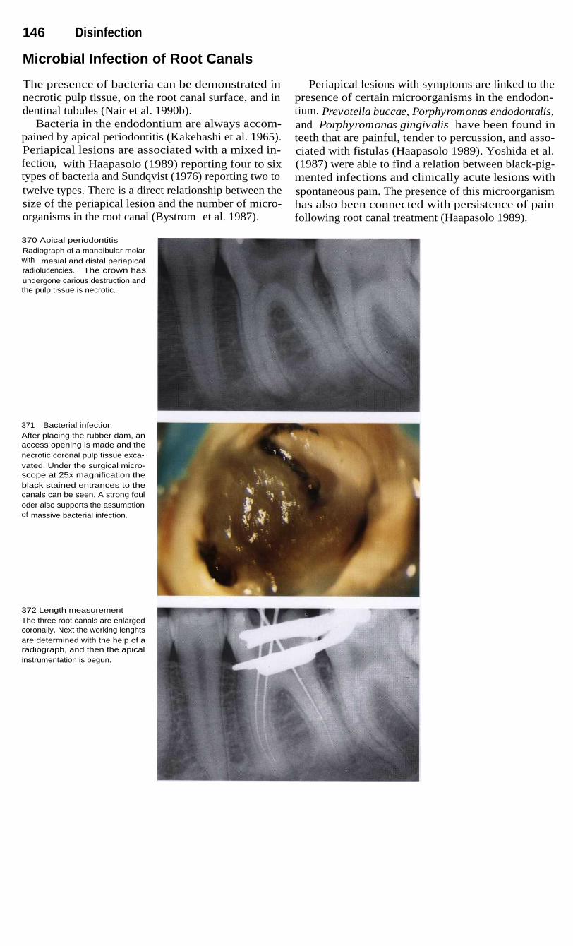
146 Disinfection
Microbial Infection of Root Canals
The presence of bacteria can be demonstrated innecrotic pulp tissue, on the root canal surface, and indentinal tubules (Nair et al. 1990b).
Bacteria in the endodontium are always accom-pained by apical periodontitis (Kakehashi et al. 1965).Periapical lesions are associated with a mixed in-fection, with Haapasolo (1989) reporting four to sixtypes of bacteria and Sundqvist (1976) reporting two totwelve types. There is a direct relationship between thesize of the periapical lesion and the number of micro-organisms in the root canal (Bystrom et al. 1987).
Periapical lesions with symptoms are linked to thepresence of certain microorganisms in the endodon-tium. Prevotella buccae, Porphyromonas endodontalis,and Porphyromonas gingivalis have been found inteeth that are painful, tender to percussion, and asso-ciated with fistulas (Haapasolo 1989). Yoshida et al.(1987) were able to find a relation between black-pig-mented infections and clinically acute lesions withspontaneous pain. The presence of this microorganismhas also been connected with persistence of painfollowing root canal treatment (Haapasolo 1989).
370 Apical periodontitisRadiograph of a mandibular molarwith mesial and distal periapicalradiolucencies. The crown hasundergone carious destruction andthe pulp tissue is necrotic.
371 Bacterial infectionAfter placing the rubber dam, anaccess opening is made and thenecrotic coronal pulp tissue exca-vated. Under the surgical micro-scope at 25x magnification theblack stained entrances to thecanals can be seen. A strong fouloder also supports the assumptionof massive bacterial infection.
372 Length measurementThe three root canals are enlargedcoronally. Next the working lenghtsare determined with the help of aradiograph, and then the apicali nstrumentation is begun.

Microbial Infection of Root Canals
14 7
In another study Orstavik et al. (1991) investigatedthe effect of root canal instrumentation and placementof a dressing upon the endodontic bacterial flora. Atotal of six symptomatic and 17 asymptomatic periapi-cal lesions received endodontic treatment, duringwhich 22 of the 23 teeth tested positive for bacteria.Following rotational instrumentation with size 25 filesand irrigation with physiologic saline, 20 of the rootcanals still contained bacteria. After they were enlargedto size 35, 14 of the canals were still infected. Furtherenlargement through size 80 did not result in any
significant improvement. After 7 days with calciumhydroxide dressings in place, only eight root canalswere infected with bacteria. Following one more en-largement of each canal by one instrument size, onlyone or two dentin samples were still infected. Theresults of this study clearly demonstrate how importanta purely mechanical instrumentation of the root canal isfor reducing the bacterial flora, and they document theantimicrobial effect of the interim dressing.
373 InstrumentationLeft: With the help of RC-Prep thecanals are enlarged coronally andthen, using the balanced forcetechnique, are shaped apically.Canals are irrigated with a sodiumhypochlorite solution.
Right: The complete instrumenta-tion of the root canals has elimi-nated most of the bacteria.
374 Antibacterial effectThe zone of inhibition around thecalcium-hydroxide-filled test tubei n the center indicates antibacteri-al activity.
Left: A zone of inhibition on anagar dish inoculated with Bacte-roides.
Right: A zone of inhibition on anagar dish inoculated with Strepto-coccus.
375 Clinical effectTreatment is accomplished bymechanical cleansing and the anti-bacterial action of medicated irri-gants and dressings. It is importantto allow enough time for the medi-caments to exert their full effect.
Left: Condition immediately afterroot canal obturation.
Right: Regeneration of the peri-apical radiolucency after 8 months.

148 Disinfection
Root Canal Irrigation
Martin (1976) compared the effects of sodium hypo-chlorite solution and a saline solution (PBS) used toirrigate infected teeth. Only the use of sodium hypo-chlorite solution brought about a reduction in micro-organisms. This has also been confirmed in the teeth ofdogs and humans by Bystrom and Sundqvist (1983)and Barnett et al. (1985). Compared with a 0.5% sodi-um hypochlorite solution, the antibacterial effect of a2.5% solution was 3.5 times greater, and that of a5.25% solution was 5.5 times greater (Yesilsoy et al.1995).
However, as a 5% solution, sodium hypochlorite isdistinctly toxic, and for this reason Spangberg et al.(1973, 1986) recommend a 1 % solution. Yesilsoy et al.(1995) determined that subcutaneous injections of 2.5%and 5.25% sodium hypochlorite solutions and a 0.12%chlorhexidine solution produced inflammation andforeign-body reactions after 2 weeks. While irrigatingwith 11.6% alcohol is hardly toxic, it does not developany antibacterial activity. From a biological perspec-tive therefore, only the 1 % and 2 % sodium hypo-chlorite solutions can be recommended (Beer 1989).
376 Apical periodontitisDuring the extraoral examination, aswelling at the right border of thelower jaw is apparent. A dentalorigin can be assumed from thetenderness to pressure, the symp-toms described, and the intraoralexamination.
Right: The mandibular right sec-ond premolar is slightly tender topercussion, but otherwise exhibitsno symptoms. A distinct periapicalradiolucency is visible on the ra-diograph.
377 Access openingThe tooth (mirror image) has beenfilled with amalgam. After makingthe access opening, a rubber dami s placed.
Right: A wisp of cotton is removedfrom the root canal. The patient re-membered undergoing root canaltreatment more than a year ago.There was no periapical radio-l ucency at the first radiographicexamination.
378 Instrumentation andi rrigation of the root canalLeft: After the coronal portion ofthe canal is opened and the work-i ng length determined; the canal isi nstrumented all the way to the api-cal constriction.
Right: I ntermittently before everychange of files, the canal is irrigat-ed with at least 2 ml of a 1% sodi-um hypochlorite solution.
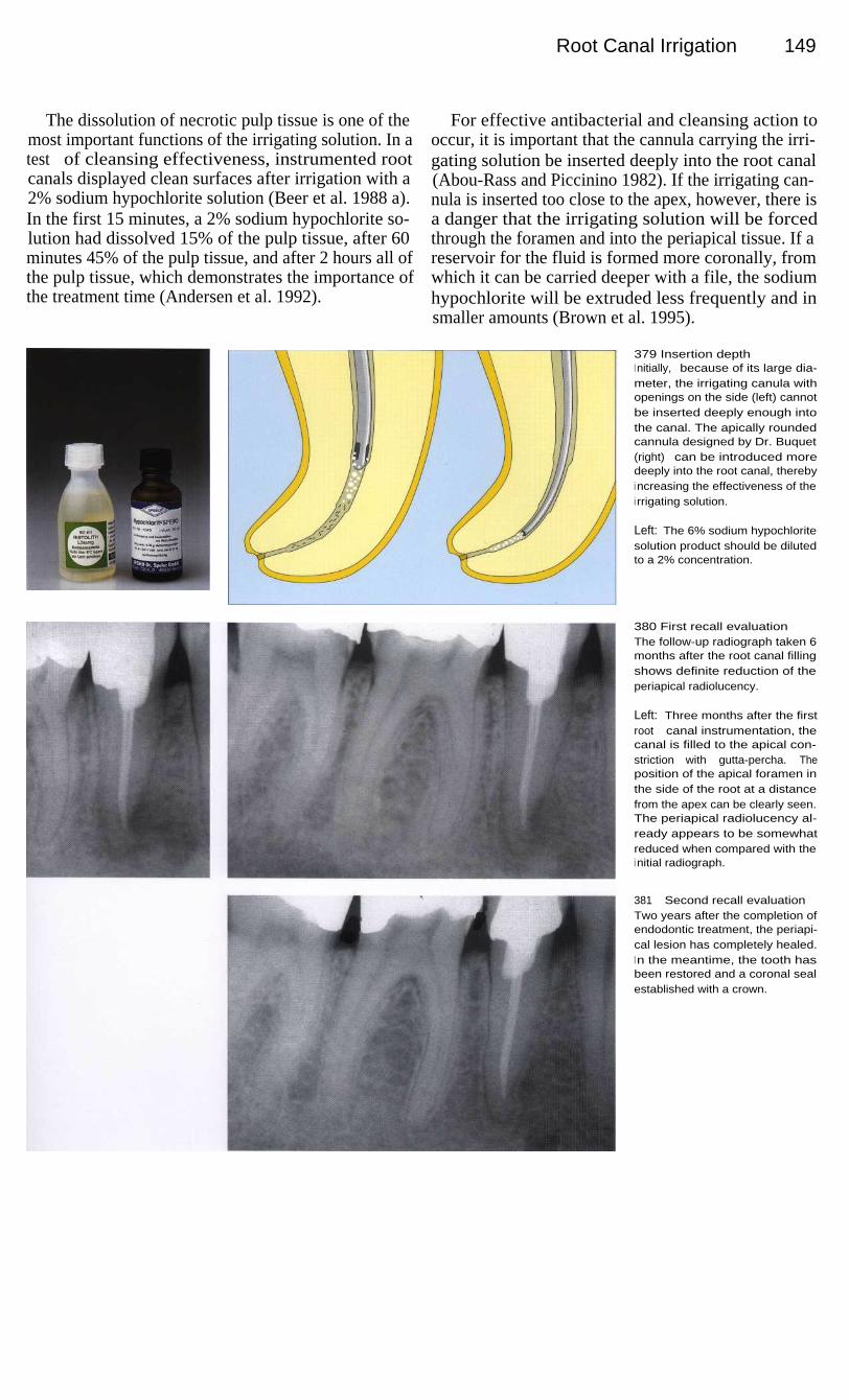
Root Canal Irrigation
149
The dissolution of necrotic pulp tissue is one of themost important functions of the irrigating solution. In atest of cleansing effectiveness, instrumented rootcanals displayed clean surfaces after irrigation with a2% sodium hypochlorite solution (Beer et al. 1988 a).In the first 15 minutes, a 2% sodium hypochlorite so-lution had dissolved 15% of the pulp tissue, after 60minutes 45% of the pulp tissue, and after 2 hours all ofthe pulp tissue, which demonstrates the importance ofthe treatment time (Andersen et al. 1992).
For effective antibacterial and cleansing action tooccur, it is important that the cannula carrying the irri-gating solution be inserted deeply into the root canal(Abou-Rass and Piccinino 1982). If the irrigating can-nula is inserted too close to the apex, however, there isa danger that the irrigating solution will be forcedthrough the foramen and into the periapical tissue. If areservoir for the fluid is formed more coronally, fromwhich it can be carried deeper with a file, the sodiumhypochlorite will be extruded less frequently and insmaller amounts (Brown et al. 1995).
379 Insertion depthI nitially, because of its large dia-meter, the irrigating canula withopenings on the side (left) cannotbe inserted deeply enough intothe canal. The apically roundedcannula designed by Dr. Buquet(right) can be introduced moredeeply into the root canal, therebyi ncreasing the effectiveness of thei rrigating solution.
Left: The 6% sodium hypochloritesolution product should be dilutedto a 2% concentration.
380 First recall evaluationThe follow-up radiograph taken 6months after the root canal fillingshows definite reduction of theperiapical radiolucency.
Left: Three months after the firstroot canal instrumentation, thecanal is filled to the apical con-striction with gutta-percha. Theposition of the apical foramen inthe side of the root at a distancefrom the apex can be clearly seen.The periapical radiolucency al-ready appears to be somewhatreduced when compared with thei nitial radiograph.
381
Second recall evaluationTwo years after the completion ofendodontic treatment, the periapi-cal lesion has completely healed.I n the meantime, the tooth hasbeen restored and a coronal sealestablished with a crown.

150 Disinfection
Irrigation of the Periapical Lesion
In the great majority of cases, periapical lesions resolveafter conservative endodontic treatment. A clinicalstudy by Morse et al. (1983) reported a success rate of94.5%. In 458 root canals treated, the failure rate was1.8% when there had been vital pulp extirpation and6.7% when the pulp was already necrotic. The successrate achieved through conservative treatment dependsstrongly upon the absence of bacteria, which can beachieved through effective canal instrumentation, anti-bacterial irrigation, and a bacteria-proof coronal seal(Beer and Mayerhofer 1995).
If a periapical lesion is greater than 20 mm in dia-meter, it can generally be assumed that it is a cyst (La-londe 1976), although no clear distinction can be madefrom the clinical or radiographic appearance (Block etal. 1976, Lin et al. 1996). When treating such a largeperiapical lesion, communication with the oral cavitycan be established through marsupialization, evenwithout the surgical removal of bone as in a cystotomy.The communication can be established by inserting asmall tube from the vestibular side (Freedland 1963,Wong 1991).
382 Periapical lesionLeft: A lower first molar with afistula in the buccal vestibule. Thetooth is tender to pressure andpercussion, but otherwise there innothing remarkable in its history.
Right: A large periapical radio-l ucency, approximately 20 mm indiameter, can be seen on the diag-nostic radiograph. The lesion doesnot appear sharply defined againstthe surrounding bone.
383
Fistulous tractLeft: A gutta-percha point hasbeen inserted into the fistuloustract to determine its origin.
Right: On the radiograph the pathof the fistulous tract is revealed bythe radiopaque gutta-percha pointthat ends near the tip of the distalroot.
384 InstrumentationLeft: After making the accesspreparation under the rubber damand carefully instrumenting thecanals, a large amount of pusempties from the distal root canal.
Right: In conjunction with thecoronal instrumentation the work-i ng length to the apical constric-tion is determined on the radio-graph.

I rrigation of the Periapical Lesion
151
Decompression can also be achieved by opening theperiapical lesion through the root canal. After the canalhas been enlarged with Gates-Glidden drills, a 1.2-mmdiameter stainless-steel tube is cemented in the canal.The patient is called back to the office once each weekto have the canal flushed with a 0.9% sodium chloridesolution. At the same appointment, the tube is cleanedultrasonically. After 3-4 months it can be removed, theexudation evaluated, and an interim dressing inserted(Tsurumachi and Saito 1995).
The enlargement of the apical constriction and irri-gation of the periapical lesion brings with it a numberof dangers. If the bacterially infected root canal is over-instrumented, a bacteremia will occur in almost everycase, with peptostreptococci, fusobacteria, and othermicroorganisms being found in the bloodstream (Debe-lian et al. 1992, 1995). The infusion of sodium hypo-chlorite solution produces acute reactions with pain,swelling, and tissue necrosis necessitating immediatesurgical intervention (Gatot et al. 1991) and must there-fore be avoided as a routine endodontic procedure.
385 Apical enlargementAs the root canal is instrumented itshould be enlarged in the coronaland middle thirds to a diameter ofat least 1.2 mm.
Left: The apical constriction isintentionally enlarged to allowdrainage through the root canal.A great risk is associated with thisprocedure, however.
386 Periapical irrigationThe root canal and the periapicall esion can be irrigated through ahollow needle every 2 days withsaline solution, but under no cir-cumstances should sodium hypo-chlorite (!) be used here. Once aweek the needle should be re-moved from the canal, cleaned,and sterilized.
Left: A cannula or stainless-steelneedle is cemented in the canaland the coronal portion of thecavity sealed with a provisionalfilling.
387 DangersSix months after filling the rootcanals, the overextended apicalgutta-percha has separated; a sur-gical procedure is indicated. Thetreatment procedure did not meetthe challenge.
Left: After 8 weeks of marsupia-l ization and another 3 months withan interim dressing, the rootcanals are filled. Even though thegutta-percha points are measuredand fitted, the absence of an apicalstop allows a severe overextensionto occur.

152 Disinfection
Ultrasonic Root Canal Irrigation
The ultrasonic frequencies of the units used range from25-40 kHz. During instrumentation the energy is trans-mitted mainly in the longitudinal direction with only asmall portion being converted into transverse oscilla-tions. Only a small load is required to inhibit the oscil-lations. Two important ultrasonic phenomena are cavi-tation and microstreaming. While the cavitation effectcan be observed at the tip of an ultrasonic scaler, it doesnot occur within the root canal (Ahmad et al. 1987,Lumley et al. 1988, Walmsley and Williams 1989).
Microstreaming is apparently the only advantagethat is useful in endodontics. It can be defined as theproduction of a steady unidirectional circulation offluid in direct proximity to a small, oscillating object.Numerous small eddy currents can arise, the most rapidof which are observed at the tip of the root canal in-strument. These vortices have the effect of producing adirected stream of fluid (Ahmad et al. 1987). Thisacoustic microstreaming can cause the disintegrationof bacteria and enzymes (Stock 1992).
388 Access openingLeft: Radiograph of a lower pre-molar showing an inadequate rootcanal filling and a periapical radio-l ucency. The tooth is tender to per-cussion.
Right: The pulp tissue is necroticand decomposed by bacteria,evidenced by a foul odor duringextirpation of the tissue remnants.Sodium hypochlorite i rrigationremoves the contents of the pulpchamber and begins the antibacte-rial action.
389 InstrumentationLeft: The root canal preparation isi nitiated with hand instrumentationbeginning with coronal enlarge-ment and then instrumentation ofthe apical region.
Right: The coronal portion of thecanal is further enlarged withGates-Glidden drills to permit freeoscillation of an ultrasonic filewithin the root canal.
390 Mode of actionLeft: The oscillation at right anglesto the long axis is made up ofoscillation nodes with minimumamplitude and antinodes, or loops,with maximum amplitude. The tipof the file vibrates freely with themaximum amplitude (Stock 1992).
Right: Magnetostriction occurswhen a bar-shaped ferromagneticbody is exposed to an alternatingmagnetic field. This producesmechanical vibrations.

Ultrasonic Root Canal Irrigation
153
In studies on models, Krell et al. (1998) have shownthat during the use of ultrasound the irrigating solutionreaches the end of the root canal only if the file canoscillate freely. If, on the other hand, oscillation isprevented by interference from the canal wall, the irri-gating solution does not get past the first oscillationnode. Only size 15 K files are recommended and theyshould be bent to fit the course of the canal so thatreduction of canal curvature and step formation will beavoided (Lumley et al. 1992).
A final manual rinsing with a 1 % sodium hypochlo-rite solution has proved effective in reducing the num-ber of microorganisms. This is followed by a 2% irri-gating solution. Ultrasonic irrigation with sodiumhypochlorite solutions have a definitely weaker anti-bacterial effect (Briseno et al. 1991). A histologic studyfailed to demonstrate any difference between periapicaltissue response after ultrasonic instrumentation andafter manual instrumentation. Necrotic tissue rem-nants, partially infiltrated with bacteria, were still pres-ent after both procedures (Watts and Patterson 1993).
391 IrrigationLeft: When using ultrasound, at aflow-through rate of 20 ml per min-ute, it takes at least 30 seconds forthe irrigating solution to reach theapical region of the root canal( Krell et al. 1988).
Right: After the root canal hasbeen irrigated and dried, it ispacked with calcium hydroxide asan antibacterial interim dressing.
392 Radiographic follow-upThree months after the beginningof root canal treatment the canal isfilled. The follow-up radiographshows that the periapical radio-l ucency is beginning to reduce insize compared with the initialradiograph (Fig. 388).
393 Radiographic follow-upAfter 1 year there is definite,although not yet complete, regen-eration of bone in the area of theperiapical lesion.
Whether it is clinically advanta-geous to use ultrasound as an aidi n root canal irrigation is stilldebated. The necessity of irrigationwith a sodium hypochlorite solu-tion remains undisputed, however,and the method shown in Fig. 388appears to be completely sufficient(Briseno et al. 1991).

154 Disinfection
Removal of the Smear Layer
The smear layer is formed on the canal surface as theresult of instrumentation, and closes the openings ofthe tubules. Even ultrasonic instrumentation of the rootcanals does not prevent formation of the smear layer(Baumgartner and Cuenin 1992, Lumley et al. 1992). Adistinction is made between the dentin shavings press-ed into the dentinal tubules and the smear layer lyingsuperficially on the wall of the canal. Under the elec-tron microscope the smear layer cannot be clearlydifferentiated from the remaining dentin of the root(Kockapan 1987).
The smear layer forms a diffusion barrier that re-duces the permeability of the dentin by 25-30%(Pashley et al. 1988). When the smear layer is re-moved, medicated dressings can penetrate more readilyinto the dentin of the canal wall and the antibacterialactivity is increased (Orstavik et al. 1990). The use ofEDTA and ethylenediamine as a final rinse removesthe smear layer completely and also enlarges the tubuleopenings by dissolving peritubular dentin (Goldbergand Abramovich 1977, Aktener and Bilkay 1993).
394 Smear layerA SEM picture of a root split length-
wise showing a root canal thatwas prepared with hand instru-ments.
B A closed smear layer and dis-placed dentin can be seen onthe surface of the canal.
C The smear layer is formed as aresult of instrumentation of theroot canal. Larger particles ofdentin can be seen.
D The smooth surface of thesmear layer is characteristic.The entrances to the dentinaltubules cannot be seen be-cause of the covering of abrad-ed dentin. The smear layer iscomposed of innumerable smallparticles, and it can even seallateral canals.
395 Root canal surface withand without the smear layerOn the surface to the left the smearlayer is represented in white. (Nor-mally there is no clear demarca-tion between the smear layer andthe underlying dentin.) Coarsedentin plugs block the dentinal tu-bules to depths of up to 5 lm. Thesmear layer can delay or even pre-vent penetration of microorga-nisms into the tubules.
On the right side of the drawing,i rrigation with an acidic solutionhas removed the smear layer andexposed the openings of the den-tinal tubules. This promotes thepenetration of microorganisms.The tubules can be entered andcolonized by bacteria more rapidly(Drake et al. 1994).

Removal of the Smear Layer
155
It is relatively easy for bacteria to adhere to the smearlayer. The removal of the smear layer with 6% citricacid solution and a final irrigation with sodium hypo-chlorite reduces the number of bacteria by 15% as itsimultaneously cleans the canal wall (Calas et al. 1994).
However, there are also inherent dangers in remov-ing the smear layer with chelating agents and acids.Safavi et al. (1989) removed the smear layer with 50%citric acid and inoculated the root canals. Three weekslater they found deep penetration of Streptococccusfaecium into the adjacent dentinal tubules.
In the control group without removal of the smearlayer, bacteria were observed only on the surface of thecanals. Drake et al. (1994) also found that an intactsmear layer made it more difficult for bacteria to ad-here and penetrate. It should be pointed out, however,that the smear layer can only delay and not prevent thepenetration of bacteria into the tubules (Akpata andBlechman 1982). Twenty-one days after inoculation,the test bacteria had penetrated through the dentin allthe way to the outer root surface (Nii et al. 1994).
396 Surface after removal ofthe smear layerA The root canal surface is
depicted under the SEM afterfinal rinsing with 6% citric acidand 2% Sodium hypochloridesolutions.
B The root canal surface is clean,the smear layer has beenremoved, and the dentinal tubu-les are open.
C Under higher magnification theopenings of the dentinal tubulescan be clearly seen. Removal ofthe smear layer should increasetheir permeability (Cohen et al.1970). However, no increase inpermeability through the rootcould be determined whenthere was no external root re-sorption and the cementum wasi ntact (Tao et al. 1991).
397 Bacterial penetrationA This microscopic photograph of
a transverse section of dentinshows completely open dentintubules.
B After removal of the smear layerand inoculation of the dentinalsurface with a test microorgan-i sm, bacteria penetrate deeplythe dentinal tubules.
C Tubules sectioned transverselydisplay bacteria as well as earlydemineralization.
D The prolonged action of demin-eralizing substances from bac-teria can lead to dissolution ofhard tissue and failure of end-odontic treatment.

156 Disinfection
Antibacterial Interim Dressings
In an infected root canal there can be more than 10 8bacteria (difficult-to-detect anaerobes) in each millili-ter of canal contents (Bystrom and Sundqvist 1991).Instrumentation of the root canal physically reducedtheir numbers by a factor of 1000; sodium hypochloriteirrigation reduced them again by 50% (Sundgvist1992). Medicated interim dressings used after thoroughinstrumentation and irrigation can kill remainingmicroorganisms and prevent reinfection (Staehle1993).
Medications in fluid form are carried into the canalon paper points, while paste dressings are inserted witha rotating spiral. Because bacteria are present in thedentinal tubules, interim dressings must make directcontact with the wall (Armitage et al. 1983). In onestudy of infected root canals, medicated dressings wereremoved from the canals after periods of l, 3, 7, and 45days, and their antibacterial effect was determined.After only 1 day, fluid medications exerted no furtherantibacterial activity (Tronstad et al. 1985).
398 Pulp necrosisA crowned mandibular first molarwith periapical radiolucency andpulp-tissue necrosis. Leaking mar-gins of the restorations and sec-ondary caries have led to infectionof the root canals. Viable bacteriacan be found in dentinal tubulesup to 2 mm from the canal wall(Ando and Hoshino 1990). Endo-toxins can also penetrate as far as300 mm into the dentinal tubules(Horiba et al. 1990).
399 Emergency treatmentAfter coronal opening and pulpextirpation the working length isdetermined and the root canals in-strumented. A cortisone-antibioticpreparation can be used as ashort-term dressing to prevent thepainful symptoms of irreversiblepulpitis, but its use is contraindicat-ed when the pulp is necrotic andthe root canal is infected becausei t will interfere with the body's owndefense mechanisms (Seltzer andNaidorf 1985).
400 InstrumentationMost of the bacteria are eliminatedby instrumenting the canals to theapical constriction and irrigatingthem with sodium hypochloritesolution. Interim dressings havesome ability to kill bacteria anddissolve tissue, but they cannotcompensate for inadequate me-chanical and chemical cleansing.
Right: One component of effectivei nstrumentation is the determina-tion of the working length.

Antibacterial Interim Dressings
157
Phenolic compounds such as cresol, thymol, andchlorophenol are expected to produce microorganism-reducing and, to some extent, pain-alleviating effects.In a risk-benefit comparison, the microorganism-re-ducing effect outweighed the intrinsinc toxic propertiesonly in the short term (Tronstad 1991). Fehr et al(1992) warn strongly against the use of formaldehydeand its derivatives because of possible allergeniceffects; Belanger (1988) refers to their mutageniceffects. Similar side effects can be expected fromglutaraldehyde (Yacobi et al. 1991).
There is no indication for the use of dressings con-taining cortisone and antibiotics in asympotomaticteeth, nor can these be depended upon to preventpostendodontic pain (Trope 1990). Cortisone prepara-tions can impair the body's own defense meachanismsand may have undesirable side effects. The inflamma-tory process, which is necessary for defense and heal-ing, is suppressed and the pulp tissue is thereby mademore susceptible to bacterial invasion and toxins (Selt-zer and Naidorf 1985, Staehle 1993).
401
Interim dressingThe most prominent temporarydressing medication at the presenttime is calcium hydroxide (Ca[OH]2)that is placed into the root canal asan aqueous suspension by meansof a rotating spiral.
Left: Calcium hydroxide (Calxyl) iseasy to apply and remove. It has avery good antimicrobial actionwhen in direct contact with dentinand no undesirable side effects.
402 Treatment resultAfter at least 1-3 months the inter-i m dressing is flushed from thecanal with sodium hypochlorite so-l ution. Further instrumentation isnot desirable. The canals are driedand filled with gutta-percha.
Left: After every treatment theaccess opening must be tightlysealed to prevent bacterial reinfec-tion.
403 Radiographic follow-upA radiograph taken after 1 yearshows complete regeneration ofthe periapical bony lesion. Theoverfilling of the root canal withi odoform to "sterilize" the pulptissue is without any scientificfoundation, leads to uncontrolledi nflammation, and is indicated nei-ther as an interim dressing nor asa definitive filling (Martin 1991).
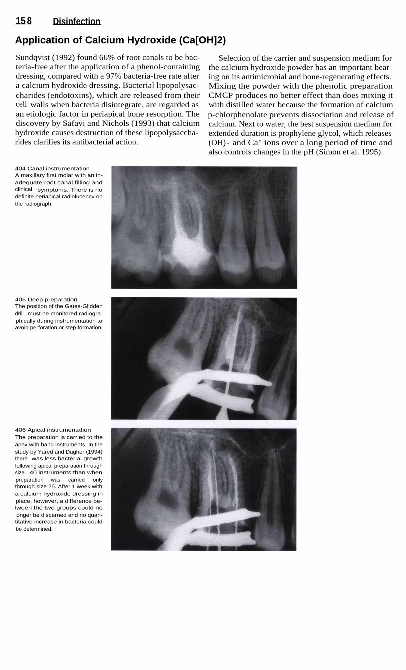
15 8 Disinfection
Application of Calcium Hydroxide (Ca[OH]2)
Sundqvist (1992) found 66% of root canals to be bac-teria-free after the application of a phenol-containingdressing, compared with a 97% bacteria-free rate aftera calcium hydroxide dressing. Bacterial lipopolysac-charides (endotoxins), which are released from theircell walls when bacteria disintegrate, are regarded asan etiologic factor in periapical bone resorption. Thediscovery by Safavi and Nichols (1993) that calciumhydroxide causes destruction of these lipopolysaccha-rides clarifies its antibacterial action.
Selection of the carrier and suspension medium forthe calcium hydroxide powder has an important bear-ing on its antimicrobial and bone-regenerating effects.Mixing the powder with the phenolic preparationCMCP produces no better effect than does mixing itwith distilled water because the formation of calciump-chlorphenolate prevents dissociation and release ofcalcium. Next to water, the best suspension medium forextended duration is prophylene glycol, which releases(OH)- and Ca" ions over a long period of time andalso controls changes in the pH (Simon et al. 1995).
404 Canal instrumentationA maxillary first molar with an in-adequate root canal filling andclinical symptoms. There is nodefinite periapical radiolucency onthe radiograph.
405 Deep preparationThe position of the Gates-Gliddendrill must be monitored radiogra-phically during instrumentation toavoid perforation or step formation.
406 Apical instrumentationThe preparation is carried to theapex with hand instruments. In thestudy by Yared and Dagher (1994)there was less bacterial growthfollowing apical preparation throughsize 40 instruments than whenpreparation was carried onlythrough size 25. After 1 week witha calcium hydroxide dressing inplace, however, a difference be-tween the two groups could nolonger be discerned and no quan-titative increase in bacteria couldbe determined.

Application of Calcium Hydroxide (Ca[OH] 2) 159
Calcium hydroxide powder alone can be introducedinto sharply curved root canals only incompletely andwith difficulty, and therefore must be mixed with aliquid. When a paste of calcium hydroxide suspended insyntetic glycerin is spun into curved root canals with aLentulo spiral, a more complete and homogenous fillingis produced than when the calcium hydroxide is mixedwith sterile water. A dense filling of the apical third wasachieved in half of the canals by using this glycerin-based paste, but in none of the canals when the aqueousmixture was used (Rivera and Williams 1994).
For curved canals prepared throught size 25, flexibleMcSpadden Compactors or Lentulo Spiral Paste Fillersare recommended. With these the interim dressing canbe conveyed to the apical region in 87% of cases. Theinjection technique adequately filled 48% of the rootcanals, and a K file rotated counterclockwise placedthe paste correctly in only 21.7% of the cases. Over-extended calcium hydroxide is quickly resorbed butcan cause a brief acute inflammatory response (Ors-tavik et al.1991).
407 Interim dressingDuring instrumentation the workinglength and the efficiency of canalenlargement are monitored radio-graphically with files in place.Finally, an interim dressing isi nserted. The antibacterial dressingshould reach any remaining bacte-ria that were not removed duringi nstrumentation and that wouldotherwise multiply rapidly betweenappointments if the canals remain-ed unfilled (Bystrom et al. 1985,1 987).
408
Insertion of the interimdressingLeft: The three root canals havebeen instrumented, irrigated, anddried.
Center: A McSpadden Compactorcoated with an aqueous calciumhydroxide suspension is insertedi nto the root canal while rotating atlow speed.
Right: As the rotating compactor iswithdrawn from the canal with acircumferential movement, thedressing is applied to the canalwalls.
409
Root canal obturationThe presence of a calcium hydro-xide interim dressing for 1 weekenables a more tightly sealedgutta-percha root canal filling. In astudy, the linear penetration of adye past the gutta-percha mea-sured 1.3 mm after a calcium hydr-oxide dressing had been used,compared with 6.6 mm in the con-trol group with no interim dressing(Porkaew et al. 1990). An interimdressing should always be usedregardless of the initial radiogra-phic appearance.

160 Disinfection
Interim Dressing for Chronic Apical Periodontitis
Because chemomechanical instrumentation alone doesnot remove all tissue remnants from curved canals(Langeland et al. 1985), the importance of the interimdressing is equal to that of root canal irrigation. Theanaerobic conditions within a sealed root canal have noinfluence on the dressing's tissue-removing properties.After 7 days calcium hydroxide had dissolved the tis-sue quite well. Its tissue-removing effect is slower andmore continuous than the initial rapid effect of sodiumhypochlorite solution (Yang et al. 1995).
Pulp tissue is loosened up after 3 hours in 0.5%sodium hypochlorite if the solution is renewed every30 minutes. In a calcium hydroxide suspension it iscompletely broken down after 12 days. If the tissue hasbeen pretreated in calcium hydroxide, it will be com-pletely broken down in sodium hypochlorite after only60 minutes (Hasselgren et al. 1988). A calcium hydrox-ide dressing in place for only 1 week will break up anuninstrumented odontoblastic layer, and a 4-weektreatment will erode a predentin layer with no furtherdissolution of hard tissue (Wakabayashi et al. 1995).
410 Apical periodontitisAccidental discovery of chronicapical periodontitis during radio-graphic examination preliminary toa prosthodontic reconstruction.There was no pain or other symp-toms associated with the mandibu-lar first premolar, and the patienthad reported no painful episodesi n the past.
411
Root canal irrigationAfter the pulp chamber is opened,the tissue remnants extirpated, andthe root canal instrumented, thecanal is irrigated freely with a 2%sodium hypochlorite solution. Theduration of this treatment has ani nfluence on the result. The irrigat-i ng solution should be allowed towork for at least 1 hour during in-strumentation, as this will flush out50% of the pulp-tissue remnants(Anderson et al. 1991).
Right: Drying of the root canal withpaper points.
412 Interim dressingThe dressing must be carefullypacked into the root canal withpaper points to ensure goodcontact with the dentin walls.
Right: Compacting the aqueoussuspension with dry paper pointsdraws out excess water and stabi-lizes the calcium hydroxide. In thisway a homogenous filling extend-i ng to the apex is achieved.

I nterim Dressing for Chronic Apical Periodontitis
Investigations under the light microscope indicatethat a 1-week dressing in conjunction with irrigationwith sodium hypochlorite during instrumentation willcompletely clean the isthmus of the mesial canals ofmandibular molars. The addition of ultrasonic oscilla-tions does not improve the cleansing effect (Metzlerand Montgomery 1989). Hydroxyl ions diffuse throughdentin with a maximum pH value when the dressing isin place for at least 3 weeks. The maximum pH valueof 10.8 is reached on the inner dentinal wall of thecanal after 24 hours (Nerwich et al. 1993).
The longer the interim dressing acts in the rootcanal, the better the regeneration of the inflamed pulptissue. Trope et al. (1995b) compared the short-termand long-term effects of calcium hydroxide histologi-cally in experimentally induced apical periodontitisand found that regeneration of bone occurred in only50% of the cases treated with a dressing for 1 week. If,however, the medication was changed every week for12 weeks, complete tissue regeneration with cementumapposition occurred.
413
Evaluation of the interimdressingA radiograph taken after the inter-i m dressing has been in place for3 weeks already shows incipientregeneration of the periapical lesi-on. While the additon of a radi-opaque substance to the calciumhydroxide interim dressing wouldfacilitate its radiographic identifica-tion, it would also make any peri-apically extruded paste less re-sorbable.
Left: The root canal is filled to justbelow the dentinoenamel junction.
414 Root canal obturationThe medicated dressing is changedafter 3 weeks because it was be-ginning to break down. After anadditional 3 months the interimdressing is loosened up with aHedstrom file and flushed out withsodium hypochlorite solution with-out further instrumentation of thecanal. The canal is then obturated.I n the meantime, the periapicalradiolucency has become substan-tially reduced.
415 Radiographic follow-upLeft: The 8-month radiographshows further regression of theperiapical lesion.
Right: After 1.5 years the periapi-cal lesion can no longer be seenon the radiograph.

162 Disinfection
I nterim Dressing for Acute Apical Periodontitis
With acute apical periodontitis the transition to an al-veolar abscess in the endosseous phase is fleeting andthis makes a clear diganosis difficult. Classic symp-toms are a pulsating, radiating pain, a feeling of toothelongation, and increased tooth mobility.
An access opening is made with a rubber dam inplace, and in many cases this is followed by sponta-neous drainage of purulent exudate, usually mixed withblood. Intensive irrigation with sodium hypochlorite iscarried out with interruptions for 15 minutes or moreuntil the exudation ceases. The root canal is dried and
a calcium hydroxide suspension is loosely insertedwith a rotating instrument. In one study, teeth with api-cal periodontitis that were obturated at the first ap-pointment were found after 9 months to have persistingacute inflammation with resorption of cementum anddentin. Eighty percent of these cases had abscess for-mation. If, on the other hand, a calcium hydroxidedressing was left in place for 7 days before obturation,the periapical lesion was replaced by new bone eventhough leucocytic infiltration could be observed in18.8% of these cases (Leonardo et al. 1995).
416 SwellingThe patient complained of severeproblems in the maxillary anteriorregion with radiating pain and aswelling that was visible extraoral-ly.
Right: The radiograph shows peri-apical radiolucencies on both cen-tral incisors. Based on the clinicaland radiographic findings, it is as-sumed that this is an acute exacer-bation of previously chronic apicalperiodontitis.
417 Intraoral appearancePrimary and secondary acute ab-scesses present the same clinicalsymptoms: increased tooth mobili-ty, sensitivity to pressure in the api-cal region, and vestibular swelling.Here the swelling is not yet fluc-tuant.
Right: The anesthetized tooth isstabilized while the pulp chamberis opened with a diamond stone ina high-speed handpiece with cool-i ng spray.
418 DrainageA Hedstrom file is inserted shortof the apical constriction. This isfollowed by a spontaneous out-flowing of pus.
Right: The root canal is enlarged,instrumented, and irrigated withsodium hypochlorite for 15 minu-tes or more until the exudationsubsides.

I nterim Dressi ng for Acute Apical Periodontitis 163
The access opening is sealed after the interim dress-ing is inserted. After 7 days the dressing is changed andcalcium hydroxide is packed into the root canal withpaper points. Acute reactions occur in only 5% of teethwith alveolar abscesses that had the coronal openingsealed (August 1982). The interim dressing and thedefinitive seal prevent reinfection and increase thesuccess rate for conservatively treated teeth to 61.1%compared with a success rate of 22.2% with no inser-tion of antibacterial dressing (Leonardo et al. 1994).
The second dressing is allowed to act for a longerperiod and should remain in the root canal for at least3 months. Calcium hydroxide exerts an excellent anti-microbial action within a sealed root canal. In vitro,anaerobic strains of bacteria such as peptostreptococci,porphyromonas, and fusobacteria could no longer befound (Georgopoulou et al. 1993). The relatively highpH value of 13.1 was kept constant for a period of 30days during the study so that a good antimicrobialeffect over a long period of time was assured (Fuss etal. 1996).
419 InstrumentationThe working length and the size ofthe initial apical files are deter-mined and then, at the first ap-pointment, both root canals arecompletely instrumented.
Left: Radiographic determinationof the working length. The lengthsare corrected for the underinstru-mentation in one and the overin-strumentation in the other.
420 Interim dressingIf there is little or no purulent exu-date the root canals are dried andfilled with calcium hydroxide.
Left: The radiographic follow-up at1 week shows resorption of the in-terim dressing. Because the initialsecretion persisted, it was neces-sary to change the dressing. Theclinical symptoms had alreadysubsided after the first appoint-ment.
421
Monitoring the course ofhealingLeft: Three months after instru-mentation there are no clinicalsymptoms, and the periapical le-sion shows signs of healing, theroot canals are therefore obturat-ed.
Center: At 6 months, further re-duction of the periapical radiolu-cency is visible.
Right: On the follow-up radiographafter 1.5 years no periapical le-sions are visible.

164 Disinfection
Clinical Results
When calcium hydroxide is used as an interim dress-ing, after 3 years there is complete regeneration of 82%of all periapical lesions, even the larger ones. In 18% ofthe cases periapical radiolucencies persist or are onlyslightly reduced. The greatest reduction of a periapicallesion occurs during the first year (Eriksen et al. 1988).The first evidence of healing is seen on the conven-tional radiograph after 12 weeks at the earliest, but canbe detected as early as 3-6 weeks in digitized images(Orstavik 1991).
Pain occurs much more frequently in small than inlarge periapical lesions (Torabinejad et al. 1988).Prophylactic administration of an antibiotic does notreduce postendodontic pain any more than a placebo(Walton and Chiapinelli 1993). If a tooth is left open,periapical inflammation, microabscesses, and resorp-tion of dentin, cementum, and bone can be observed. Ifthe canal is packed with an interim dressing, reparativecementum will form and the size of the periapicallesion will be reduced (Holland et al. 1992).
422 Apical periodontitisA mandibular molar with a defec-tive amalgam filling and extensiveperiapical lesion. This is locatedprimarily on the mesial root andextends into the bifurcation space.
Right: A vestibular fistula fromwhich pus drains periodically isvisible clinically.
423 Root canal treatmentThe root canal is instrumented,generously irrigated with sodiumhypochlorite solution, treated witha calcium hydroxide interim dress-i ng for 6 months, and then obturat-ed. Incipient regeneration of bonecan be seen radiographically inthe area of the periapical lesion.
424
Radiographic and clinicalfollow-upThe radiograph made after 1.5years shows complete healing ofthe once extensive periapicallesion.
Right: Clinically, the fistulous tractcan no longer be found. The teethcan now receive fixed restorations.

16 5
Root Canal Obturation
The last step in root canal treatment is to create the best possible hermetic seal with a fillingmaterial that is nonirritating to the tissues. The basic mechanical instrumentation and shaping ofthe canal is the most important prerequisite for endodontic success. If the root canal is onlypartially instrumented, successful treatment cannot be expected. The root canal filling shouldleave the tooth in the most biologically inert condition possible, and it must prevent reinfectionas well as growth of any microorganisms remaining in the canal (Beer 1993 a). In animal experi-ments it was found that resorbable pastes extruded into the periapical space led to infiltration ofacute inflammatory cells, resorption of the adjacent alveolar bone, and in a few cases, to abscessformation (Erausquin and Muruzabal 1969). When a canal was filled with a polyketone-basedsynthetic resin cement, the pulp tissue became inflamed with macrophages and foreign-body giantcells predominating. Here, too, an acute inflammatory reaction could be seen in a few instances(Erausquin and Muruzabal 1970). Over-filling with this cement prompted necrosis and varyingdegrees of resorption of cement and bone. After 80 days, a capsule had formed around the over-extended material. Resorption of the cement did not occur but there was a definite foreign-bodyreaction. Filling a root canal with the formaldehyde-containing root canal cement N2 broughtabout a foreign-body reaction: zones of necrosis and accumulations of leukocytes were observedbordering on the fixed tissue. This filling material is continuously resorbed and diffuses throughthe pulp tissue to be distributed throughout the entire body (Horsted et al. 1982).
The ideal root canal filling material would be nonirritating to the pulp tissue, would tightly sealthe canal both laterally and vertically, and would be dimensionally stable so as not to shrinkwithin the canal. It should not support bacterial growth and should even be bacteriostatic, whileat the same time being biologically compatible and nontoxic. The filling material should be easyto sterilize before use. It should be radiopaque and should not discolor the tooth. A root canalsealer should not harden too quickly and after hardening should exhibit good adhesion to both thedentin and the root canal filling. It should be insoluble in tissue fluids and have a slight expansion(Ngyuen 1994). No one formulation can fulfill all these requirements, however, and a greatnumber of different endodontic filling materials and techniques fall short. Filling the root canalwith gutta-percha points and a sealer is the most biologically favorable and surest method in thelong term (Orstavik et al. 1987). Widely used methods of gutta-percha application include lateralcondensation, vertical condensation, thermomechanical condensation, and injection techniques.

166
Root Canal Obturation
Biological Properties
All root canal cements are tissue irritants and onlygutta-percha is biologically inert (Beer 1986). Onehundred and eighty days after they implanted chloro-percha subcutaneously, Olsson et al. (1981) foundchronic inflammation with small foci of necrosisfollowed by a zone of disintegrated cells at the end ofthe carrier tube. Acute inflammation predominatedafter chloropercha had been implanted in bone for 180days, whereas chronic inflammation was evoked byAH-26 and Kerr Sealer. All sealers tested experiencedresorption by macrophages (Olsson et al. 1981).
Under clinical conditions, AH-26 produced severereactions in pulp tissue with infiltration of neutrophilicgranulocytes and macrophages after 7 days. Nobacteria could be found in any of the teeth investigated.After 30 days a chronic cellular infiltrate predomi-nated, regardless of which of the filling cements beingtested was used. The reaction to AH-26 was severe atfirst but markedly less so after 3 years. In contrast, thereaction to chloropercha was mild initially but becamesevere during the time frame of the study (Pascon et al.1991).
425 Subcutaneous implanta-tion of Grossman cementA Soft and hard cements can be
i nvestigated by using Teflontubes as carriers.
B A severe tissue reaction to thetest material can be seen facingthe opening of the tube.
C Accumulation of acute andchronic inflammatory cells.
D, E, F
An accumulation of mo-nonuclear inflammatory cellscomposed of lymphocytes,plasma cells, and macrophagesis an expression of a persistenti nflammatory stimulus. Particlesof the material found throughoutthe tissue as well as within themacrophages testify to its re-sorbabi I ity.
426 Tissue reaction toimplanted DiaketA The tissue tube has been re-
moved from the rat connectivetissue.
B, C Facing the opening of thetube a moderate inflammatoryreaction with massive lym-phocytic infiltration is found.
D The accumulation of macro-phages is evidence of activephagocytosis of cement par-ticles, and the appearance oflymphocytes and plasma cellsi n an expression of an immuno-logic reaction.
E The image under polarized lightreveals individual particles ofcement distributed both throughthe tissue and inside the phago-cytes.

Biological Properties
167
Physical Properties
Among the physical properties of a sealer are the capac-ity to provide a marginal seal, condensability, shrink-age, and viscosity. Many studies have been conductedto evaluate these criteria and have produced variousresults. Wiener and Schilder (1971) investigated thedimensional changes by filling micropipettes asmodels for root canals. The sealers that had detachedmost were also the first to show signs of shrinkage.Only AH-26 expanded slightly after 7 days, and thenexhibited a slight shrinkage after 30 days.
Orstavik (1982) investigated the film thicknesses of28 sealers. These ranged from 4.5 to 10 hum. There wasa relationship between the film thickness and the complete seating of the gutta-percha points: the greater thefilm thickness, the greater the force required to bringthe point to the measured position. The best valueswere achieved with Kerr sealer and Proco-Sol. Osinuset al. (1983) compared various sealers and obturationmethods: the best seal was obtained with the verticalcondensation technique and AH-26, and the techniquesthat used no sealer produced the worst results.
427
Dye penetration test of aglass ionomer cementExtracted teeth are instrumented,and their canals filled and subject-ed to a dye penetration test to eval-uate the tightness of the seal.
A Dye is found 1 mm above theapex between the root canalfilling and the canal wall.
B There is visible penetration 2 mmabove the apex.
C Only at a distance of 8 mm isthere almost no dye present.
D Dye between the canal wall andthe filling as well as within theglass ionomer cement indicatesan inadequate seal.
428
Dye penetration test ofAH-26I n comparing different obturationmethods the difference in theirsealing abilities is of great impor-tance. Penetration tests provide re-sults that, while not absolute, are abasis for comparison.
A 1 mm from the apex almost nodye penetration is seen; theroot canal is obviously well-sealed.
B At a distance of 2 mm the firstvoid is found within the fillingmaterial.
C This higher magnification showsa bubble formed within thematerial, which indicates insuffi-cient homogeneity.

168
Root Canal Obturation
Prerequisites for Filling the Root Canal
A root canal can be obturated when there is no pain,swelling, tenderness to percussion, or fistulation asso-ciated with the tooth, and when the instrumented canalis dry and free of odor. If the pulp is necrotic or a peri-apical lesion is present, the root canal cannot be filledbefore the second appointment. At the first appoint-ment vital pulp tissue can be completely removed bymeans of hand instruments or ultrasonic instrumentsfrom only 54% of root canals that have a 35° curvature(Walker and delRio 1989).
Therefore curved canals should also not be filleduntil the second appointment.
When apical periodontitis is present, endodontictreatment in a single visit produces a significantlypoorer result than treatment that includes antibacterialdressings in place between multiple appointments(Holland et al. 1992).
429
Initial clinical situationThe diagnostic radiograph shows aperiapical radiolucency at the tipof the mesial root of the maxillaryfirst molar. The gutta-percha pointreveals the origin of the fistuloustract.
Right: A gutta-percha point hasbeen inserted into the fistuloustract. Because of its radiolucency,the gutta-percha should point tothe origin of the fistula on theradiograph.
430 Canals disclosedAfter making the coronal accessopening, the working lengths of thethree root canals are determinedradiographically. Then they are in-strumented and filled with calciumhydroxide.
Right: Because the fistula per-sisted, the tooth is opened againand the floor of the pulp chamberi nspected for entrances to any ad-ditional canals.
431
Fourth root canalA fourth, mesiolingual canal isfound in the mesiolingual root. Twofiles are then inserted to determinethe patency and relationship of thetwo canals in the same root. Thefourth canal is located with thehelp of a small, long-shanked,round bur. Then it is carefullyprobed and instrumented.

Prerequisites for Filling the Root Canal 169
If the root canal is infected, the filling materialshould have a strong antibacterial action. In diffusiontests, the strongest antibacterial effect was produced byEndomethasone and N2, followed by AH-26 (Puma-rola et al. 1992). In biologic implantation tests, however,Endomethasone and N2 brought about the most severetissue reaction. AH-26 prompted a tissue reaction thatwas severe initially but became milder over the periodof the study, while Grossman cement caused a per-sisting moderate irritation (Orstavik and Mjor 1988).
Sealers containing calcium hydroxide were some-what more efficient in destroying bacteria than resinbased sealers (Canalda and Pumarola 1989). AH-26and Sealapex exhibited strong antibacterial activitywithin adjacent dentin tubules (Heling and Chandler1996). Their biologic reaction is objectionable, how-ever. Sealapex triggered a foreign-body reaction withinfiltration of giant cells and macrophages. The re-action in implantation tests intensified during the 30and 90 days of the investigation (Zmener et al. 1988).
432 Radiographic evaluationThe position of all four gutta-per-cha points within the root canals ischecked with the master pointradiograph.
Left: The root canals were notcompletely dried before the masterpoint radiograph and can still bei nstrumented further if necessary.
433 Optical evaluationThe results of the instrumentationare evaluated under the surgicaloperation microscope. Usingstronger magnification straight rootcanal segments can be "traveled"from their apical ends to theircoronal regions by adjusting thefocus.
Left: The view into the preparedcavity shows the canal enlarge-ment and the round-shaped rootcanal entrances.
434
Root canal fillingThe root canals are obturated withgutta-percha and a sealer by thelateral condensation technique.The image of the mesiobuccalcanal is superimposed over that ofthe fourth canal so that their fillingsappear as one.
Left: Under the surgical operationmicroscope the gutta-perchapoints are shown to be well con-densed. The working depth in themesiolingual canal is being re-checked with a spreader.

170
Root Canal Obturation
Lateral Condensation of Gutta-percha
The root canal filling procedure starts with the selec-tion of the gutta-percha master point. Gutta-perchashould not be stored too long or it will become brittleand weak and will no longer be easily condensed. Thisproblem can be traced back to its transformation intocrystalline form, which is accelerated by light and heat.Gutta-percha that has not dried out can be shaped morereadily (Kolokuris et al. 1992). When stored in a re-frigerator, gutta-percha contracts and becomes harder,but not more brittle (Best et al. 1963). Softer gutta-per-cha points can be better condensed (Hulsmann 1993 b).
Before the gutta-percha master point is tried in thecanal, a suitable spreader is selected. The compactnessachieved in a root canal filling depends upon the inser-tion depth and the shape of the spreader. The distancewithin the root canal between the tips of the gutta-percha point and the conically tapered D-11 spreader ismore than 2 mm. The ISO standardized finger spreader,on the other hand, can be inserted to 1 mm from the tipof the gutta-percha point, resulting in a more homo-genous and denser root canal filling (Chohayeb 1993).
435 Vital extirpationA maxillary incisor with irreversiblepulpitis. After the rubber dam isplaced, an access opening ismade and vital extirpation of thepulp is performed.
Right: The root canal is almoststraight with a slight distal curva-ture so that it can be prepared andobturated at the same appoint-ment.
436 Master pointLeft: The working length is deter-mined. The root canal is then pre-pared, irrigated, and dried.
Center: A gutta-percha masterpoint corresponding to the size ofthe AMF is selected and the work-i ng length marked by the imprint ofa pair of pliers.
Right: The gutta-percha point istried in the canal for correct fit andlength. It should end slightly shortof the apical extent of instrumenta-tion.
437 Root canal cementLeft: The cement is mixed andgiven the spatula test to determinethe desired consistency.
Center: The apical half of the mas-ter point is coated with sealer andi nserted into the canal to the pre-determined depth.
Right: Apexit, a resin-based sealercontaining calcium hydroxide,seals the root canal better thanSealapex and Tubliseal (Limkang-walmongkol et al. 1991).

Lateral Condensation of Gutta-percha
In slightly curved root canals, finger spreaders con-dense the gutta-percha better than hand spreaders of thesame shape, presumably because of the freer move-ment and rotation of the finger spreaders (Simons et al.1991).
The risk of a vertical fracture during condensation isvery small and depends upon the design of the spreader.Conical spreaders produce dentin deformation withexpansion four times more frequently than standardizedfinger spreaders. Vertical root fractures occurred in 5%of the obturated teeth (Dang and Walton 1989).
After the first condensation of the gutta-percha mas-ter point, additional accessory points are condensedagainst the canal wall. In a study by Jerome et al.(1988), root canal fillings that were placed with ISOstandardized size 25 accessory points using a fingerspreader were significantly more homogenous, bettercondensed, and exhibited no overfilling or crumpling.The use of nonstandardized fine-fine accessory pointsresulted in overfilling in 30% of the canals; the fillingsfrequently contained wrinkles, voids, and nonhomo-geneous areas.
438 Lateral condensation ofgutta-perchaLeft: The finger spreader is insert-ed between the canal wall and thepoint to a depth 1 mm short of theworking length.
Center: When the working lengthis reached, the spreader is left inplace for 15 seconds before beingwithdrawn. This will prevent re-bounding of the gutta-percha.
Right: The accessory point, coatedwith a small amount of sealer, iscondensed against the masterpoint with the finger spreader.
439 Accessory pointsLeft: The spreader is removed witha gentle rotating movement, and astandardized accessory point is in-serted into the space.
Center: Accessory gutta-perchapoints in sizes 25 and 20 are coat-ed with sealer and condensed oneupon another.
Right: The gutta-percha is con-densed to a homogeneous canalfilling.
440 Radiographic evaluationLeft: Vertical force applied to thespreader deforms the accessorypoint laterally.
Center: The gutta-percha pointsprotruding from the access prepa-ration are cut off 1 mm apical tothe canal entrance. The filling isthen evaluated for precision of fitand homogeneity.
Right: Radiographic follow-up 3years after the completion of end-odontic treatment shows noevidence of periapical irritation.
171
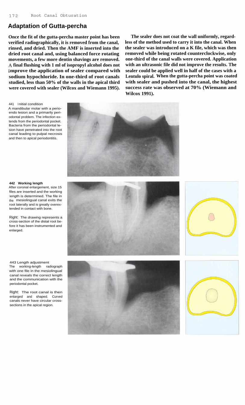
172
Root Canal Obturation
Adaptation of Gutta-percha
Once the fit of the gutta-percha master point has beenverified radiographically, it is removed from the canal,rinsed, and dried. Then the AMF is inserted into thedried root canal and, using balanced force rotatingmovements, a few more dentin shavings are removed.A final flushing with 1 ml of isopropyl alcohol does notimprove the application of sealer compared withsodium hypochloride. In one-third of root canalsstudied, less than 50% of the walls in the apical thirdwere covered with sealer (Wilcox and Wiemann 1995).
The sealer does not coat the wall uniformly, regard-less of the method used to carry it into the canal. Whenthe sealer was introduced on a K file, which was thenremoved while being rotated counterclockwise, onlyone-third of the canal walls were covered. Applicationwith an ultrasonic file did not improve the results. Thesealer could be applied well in half of the cases with aLentulo spiral. When the gutta-percha point was coatedwith sealer and pushed into the canal, the highestsuccess rate was observed at 70% (Wiemann andWilcox 1991).
441
Initial conditionA mandibular molar with a perio-endo lesion and a primarily peri-odontal problem. The infection ex-tends from the periodontal pocket.Bacteria from the periodontal le-sion have penetrated into the rootcanal leading to pulpal necrosisand then to apical periodontitis.
442 Working lengthAfter coronal enlargement, size 15files are inserted and the workingl ength is determined. The file inthe mesiolingual canal exits theroot laterally and is greatly overex-tended in contact with bone.
Right: The drawing represents across-section of the distal root be-fore it has been instrumented andenlarged.
443 Length adjustmentThe working-length radiographwith one file in the mesiolingualcanal reveals the correct lengthand the communication with theperiodontal pocket.
Right: The root canal is thenenlarged and shaped. Curvedcanals never have circular cross-sections in the apical region.

Adaptation of Gutta-percha
173
Fot the biologic evaluation of a root canal, the extentto which sealer comes into contact with the periapicaltissue is of great importance. A ratio of approximately95% biologically inert gutta-percha to 5% resorbablesealer is required. A study by Eguchi et al. (1985)reported a value of 94.5% gutta-percha at a distance of1 mm from the root rip using lateral condensation ofgutta-percha points dipped in chloroform with Proco-Seal as a sealer. Vertical condensation did not performas well with a value of 91.7%.
The film thickness of the sealer also influenced thecondensation of the root canal filling. AH-26 andSealapex were condensed to film thicknesses of0.3 mm, but Kerr sealer was best with a film thicknessof 0.05 mm (Georgopoulou et al. 1995). Nitinol spread-ers seemed to have an advantage over steel spreaders incondensing into curved root canals because theyinduced less stress. In straight canals, however, no dif-ference in the force developed nor in the condensationcould be discerned (Dwan and Glickman 1995).
444 Trial insertion of thespreaderAfter the canal has been complete-ly instrumented it is given a finali rrigation but is not completelydried. Some moisture facilitatesthe fitting of the spreader and thegutta-percha point. The model re-presents the root sectioned trans-versely 3 mm above the apex.
Left: A suitable finger spreader isselected. It should contact thecanal walls 1 mm before it wouldreach the working length. Thel ength can be marked by means ofa rubber stop.
445 Trial insertion of themaster pointsGutta-percha master points areselected that match the sizes of theAMFs. Their lengths and positionswithin the root canals aredetermined with a working-lengthradiograph.
Left: The cross-section demonstra-tes good wall contact by the firstgutta-percha point (green). It can-not completely fill the canal be-cause of the irregular shape of thel atter.
446 First condensationThe finger spreader is inserted be-tween the gutta-percha point andthe root canal wall with verticalforce as close as possible to thepremeasured depth, held there for1 5 seconds, and then removedagain with a rotating motion. Thegutta-percha is now pressedagainst the canal wall.
Left: The transverse section showsthe first condensation procedurewith lateral deformation of thegutta-percha.

174
Root Canal Obturation
447 Second gutta-perchapointLeft: The desired length has beentransferred to the gutta-perchapoint with plier beaks.
Center: The Nitinol spreader ispushed into the root canal to thedepth of the rubber stop, left therefor at least 15 seconds, and thenremoved with a gentle twisting mo-tion.
Right: A standardized size 20gutta-percha accessory point is in-serted into the space created bythe spreader.
448 Lateral condensationThe second gutta-percha point ispressed against the first point andthe canal wall by the spreader.Deformation of the gutta-perchacreates an empty space onceagain.
Right: The metal-colored spreadercondenses the second (blue)gutta-percha point against the first(green) master point.
(The colors of the gutta-perchacorrespond to the ISO colorcodes.)
449 Third gutta-percha pointThe third gutta-percha point is de-formed by yet another condensa-tion procedure with the spreaderand pressed against the first twopoints.
Right: In the cross-sectional draw-i ng, the third gutta-percha point(pink) is shown before lateralcondensation. The tips of all theaccessory points are dipped in asmall amount of sealer beforebeing inserted into the canal.
450 CondensationLeft: Condensation is continuedwith the finger spreader until it canbe inserted no farther than thecoronal one-third of the canal.
Center: Additional gutta-perchapoints are added and condensedto produce a homogeneous rootcanal filling.
Right: The drawing illustrates thelateral deformation of the thirdgutta-percha point against the firsttwo by the metal-colored spreader.

Adaptation of Gutta-percha 175
451
Radiograph during thecondensation procedureBefore the coronal excess of gutta-percha is removed, the positionand depth in the mesiobuccalcanal can be checked by insertinga finger spreader and taking a ra-diograph. In this way correctionscan still be made. The distal canalhas already been completely anddensely obturated.
452
Homogeneity of the rootcanal fillingThe cross-section shows the mold-i ng of the individual gutta-perchapoints into one homogeneousmass so that the proportion of sea-l er in the entire filling is less than5%.
Left: The drawing illustrates thelaterally condensed gutta-perchapoints. The white point fills the lastspace created by the spreader.
453
Removal of the excessgutta-percha from the crownThe gutta-percha protruding fromthe canals is removed with an ex-cavator that has been heated in analcohol flame.
454
Radiographic evaluationThe exact position of the root canalfilling is evaluated in a radiograph.The periodontal condition appearsto have become worse than it wasi nitially. Periodontal surgery willfollow the endodontic treatment.
Left: After the gutta-percha is sep-arated, it is condensed verticallywith a plugger.

176
Root Canal Obturation
Corrections During Condensation
Failure of the spreader to seat deeply enough when it istried in the canal is usually an indication that the rootcanal does not have the correct shape. The form andtaper must then be refined with prebent Hedstrom files.The cause could also lie in the wrong spreader size. Ifthe condensing instrument binds in the midregion ofthe canal, then either the canal should be widened coro-nally with a Gates-Glidden drill or a smaller spreadershould be selected. Wedge-shaped spreaders are con-traindicated because of the danger of vertical toothfracture (Lindauer et al. 1989).
The average force that can cause a fracture with aD-11 spreader is over 7.5 kg. This force fractured 3%of the teeth, whereas none were fractured during lateralcondensation with forces of 1-3 kg (Onnink et al.1994). Comparison of the apical density showed nodifference when condensation was carried out withforces between 1 and 2.5 kg (Hatton et al. 1988). Rootfractures occur when the dentin is overloaded becauseof local irregularities near the tip of the spreader (Telliet al. 1994).
455 Coronal enlargementA maxillary molar with periapicalradiolucency and a presumed re-sorption defect in the apical regionof the palatal root.
Right: Before the deep preparationis begun, the coronal portion is en-larged with Gates-Glidden drillsusing the step-down technique.
456 Working-lengthradiographThe first radiographic test of theworking length with size 15 files.The working length has not yetbeen reached in the lingual canal.
Right: The root canals are furtherprepared coronally and then in-strumented to the measured orcorrected working lengths.
457 Working-lengthradiograph
If the working length has to beadjusted by more than 2 mm, anadditional radiograph should betaken to verify the correctedlength.
Right: The root canals are instru-mented apically to the new work-ing length using the balancedforce technique.

Corrections During Condensation
177
During condensation, the gutta-percha is not onlydeformed laterally, but also pushed apically as thespreader is inserted. Total elongation is indeed, small,with an average value of 0.29 mm reported by Yaredand Dagher (1993). If an apical stop has been preparedthere should be no overextension. This danger doesarise, however, during vertical condensation and whenthere is an open apical foramen (Yared et al. 1992).
The usual causes of overextension of the gutta-percha filling are excessive instrumentation past theapical constriction, unexpected resorptive defects,
iatrogenic defects such as perforations, zips andfunneling, excessive force during condensation, andthe use of gutta-percha points that are too small (Gut-mann et al. 1991).
A radiograph of the master point is essential forevaluating its position and preventing overextension.Another radiograph can be taken during the condensingprocedure for monitoring purposes.
458 Master point radiographFollowing completion of the rootcanal preparation the three gutta-percha master points are fitted andevaluated with another radiograph.The length of the lingual pointmust be reduced by 2 mm.
Left: The three master points cor-respond in size to the AMFs andare inserted into the canals to thel ength mark (arrow). A size 40point is placed in the lingual canal.
459 Radiographic monitoringduring lateral condensationIf concerned that the lingual canalmight be overfilled, another radio-graph can be taken after the firstcondensation with the spreader inplace.
Left: A size 45 gutta-percha point,a size larger than the overextendedpoint, is condensed with a fingerspreader.
The overextended gutta-perchapoint is replaced by one a sizel arger (size 45), and the first con-densation with a finger spreader isrepeated.
460 Final evaluationA radiograph of the completed rootcanal filling is taken to evaluate itshomogeneity and apical seal. Atthis stage, corrections can bemade only through completeretreatment.
Left: Lateral condensation of addi-tional gutta-percha points in thelingual canal. The excess protrud-i ng from the tooth will then beremoved.

178
Root Canal Obturation
Gutta-percha Master Point Too Long
Root canal sealing cements are irritating to the tissuesand can be resorbed, whereas gutta-percha is biologi-cally inert. Because gutta-percha by itself does not ad-here to the walls to form a hermetic seal, a sealer mustbe used with it. If gutta-percha and Grossman cementare overextended, the tissue reaction in most cases isslight: a circumscribed inflammatory reaction sur-rounds extruded particles of sealer, and a thin connec-tive-tissue capsule with fibroblasts and scattered lym-phocytes forms around the gutta-percha point (Beer1989).
If overinstrumentation with enlargement of the api-cal constriction has occurred, the fitting of the gutta-percha master point must be given special attention. Anadvantage of the lateral condensation technique is thatcorrections are still possible during the condensationprocedure. On the other hand, the danger of extrudingpastes and cements into the periapical tissue with aspiral filler is relatively high (Kockapan 1993). Ehren-feld et al. (1992) report that when the excess fillingextended into the mandibular canal there was never fullrecovery in spite of microsurgical procedures.
461
Presenting conditionA lower molar with carious pulpexposure, pulpal necrosis, andperiapical radiolucency.
Right: With the rubber dam inplace, an access opening is made,the caries completely excavated,and the dentinal roof removed. Thecanal orifices are then probed andenlarged.
462 Working-LengthradiographAfter the pulp space is opened andenlarged coronally, the workinglength is estimated, checked with aradiograph, and adjusted if neces-sary.
Right: For better differentiation,different files are inserted in thethree root canals.
463 Master point radiographThe first working-length radio-graph after i nstrumentation i scompleted shows the distal gutta-percha point to be overextended.Mesially the working length is tooshort and has to be corrected byadditional instrumentation.
Right: The three gutta-perchapoints are inserted into the canalsto their working lengths.

Gutta-percha Master Point Too Long
179
If the master point is too long it is shortened by1 mm with a scalpel on a glass slab to leave a tip witha greater diameter. The cut end must then be smoothedby gentle rolling. Next, the gutta-percha point is dippedin a solvent and fitted to the shape of the individualroot canal. The root canal must not be completely dryor else the gutta-percha point will stick to the canalwall as it is being fitted. The apical 5 mm of the gutta-percha point is softened by either 5 seconds in chloro-form, 15 seconds in halothane, or 25 seconds in euca-lyptol (Yancich et al. 1989), Smith and Montgomery
1 992). In only 1 second gutta-percha absorbs 0.35 mgof solvent, of which 62% will have diffused away after3 minutes. Twenty percent chloroform remains on thesurface of the point (Metzger et al. 1988). The point isinserted into the canal to the depth marked and afterapproximately 15 seconds it is removed again. Afterthe canal is dried, the point is coated with sealer,reinserted, and condensed to a homogeneous, well-adapted filling (Moyer et al. 1995).
464 Master point radiographAfter shortening and customizingthe distal gutta-percha masterpoint and further enlarging the me-sial canals, the second masterpoint radiograph shows the threemaster points to be at the correctdepth.
Left: After a gutta-percha point isdipped in eucalyptol its surface issoftened (right), whereas it can bealmost completely broken down bychloroform (left).
465 Length correctionBecause gutta-percha points havea slight conical taper, an inter-mediate size can be made bytrimming 1 mm from the tip of astandard point.
Left: Only the first gutta-perchapoint matches the size of the rootcanal. Noncustomized, standardpoints are then added and con-densed laterally.
466 Gutta-percha fillingThe final radiograph of the com-pleted gutta-percha filling shows awell-adapted root canal filling.Comparison with the second ma-ster point radiograph shows thatthe filling in the distal root wasslightly displaced apically duringcondensation.
Left: Laterally condensed gutta-percha points in the distal canal.

180
Root Canal Obturation
Gutta-percha Master Point Too Short
If the gutta-percha master point does not extend to thefull working length it usually means that dentin shav-ings have accumulated in the apical third of the canaland blocked it. Other causes are coronal step forma-tion, a stepped transition from the middle to the apicalcanal section, flattening of the canal curvature withcreation of either an apical enlargement or a false path,or the gutta-percha point itself possibly being too thick.A blockage can be removed with twisting movementsof a Hedstrom file and RC-Prep (Beer and Baumann1994).
Acids and chelating agents can be used to help getthrough obliterations and blockages. However, the in-troduction of RC-Prep to overcome an obstruction canhave a negative influence on the root canal filling andits seal. Apparently some EDTA can remain on the sur-face of the canal and in the tubules and in the course oftime reduce the seal of the root canal filling (Cooke etal. 1976). If, on the other hand, the canal is rinsedintermittently with sodium hypochlorite and Salvizol,no difference in the seal can be detected (Biesterfeldand Taintor 1980).
467 Initial situationThe patient suffered indistinct dis-comfort in the maxillary posteriorregion, seemingly originating inthe second premolar, that had adeep resin filling with secondarycaries. The molar lying distal to itwas subsequently extracted be-cause of a fracture.
468 Access openingThe filling and caries are removed,an access opening made, and thecoronal segment of the canal en-l arged.
Right: During instrumentation ofthe root canal a blockage by den-tin shavings is encountered so thatthe Hedstrom file cannot be in-serted to the calculated workingl ength.
469 Master point radiographThe gutta-percha point fails toreach the desired working length.It is still short of the apical con-striction by 2.5 mm due to an ob-struction in the apical region.
Right: The gutta-percha masterpoint shown in the canal is re-moved.
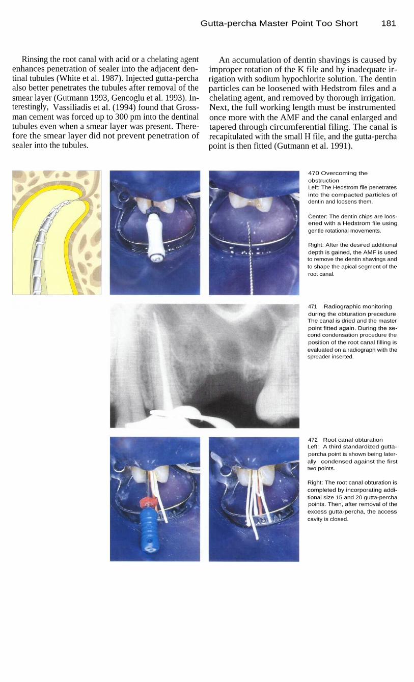
Gutta-percha Master Point Too Short
Rinsing the root canal with acid or a chelating agentenhances penetration of sealer into the adjacent den-tinal tubules (White et al. 1987). Injected gutta-perchaalso better penetrates the tubules after removal of thesmear layer (Gutmann 1993, Gencoglu et al. 1993). In-terestingly, Vassiliadis et al. (1994) found that Gross-man cement was forced up to 300 pm into the dentinaltubules even when a smear layer was present. There-fore the smear layer did not prevent penetration ofsealer into the tubules.
An accumulation of dentin shavings is caused byimproper rotation of the K file and by inadequate ir-rigation with sodium hypochlorite solution. The dentinparticles can be loosened with Hedstrom files and achelating agent, and removed by thorough irrigation.Next, the full working length must be instrumentedonce more with the AMF and the canal enlarged andtapered through circumferential filing. The canal isrecapitulated with the small H file, and the gutta-perchapoint is then fitted (Gutmann et al. 1991).
470 Overcoming theobstructionLeft: The Hedstrom file penetratesi nto the compacted particles ofdentin and loosens them.
Center: The dentin chips are loos-ened with a Hedstrom file usinggentle rotational movements.
Right: After the desired additionaldepth is gained, the AMF is usedto remove the dentin shavings andto shape the apical segment of theroot canal.
471
Radiographic monitoringduring the obturation precedureThe canal is dried and the masterpoint fitted again. During the se-cond condensation procedure theposition of the root canal filling isevaluated on a radiograph with thespreader inserted.
472
Root canal obturationLeft: A third standardized gutta-percha point is shown being later-ally condensed against the firsttwo points.
Right: The root canal obturation iscompleted by incorporating addi-tional size 15 and 20 gutta-perchapoints. Then, after removal of theexcess gutta-percha, the accesscavity is closed.
181

182
Root Canal Obturation
Thermomechanical Condensation
A compactor in the form of a reverse Hedstrom filerunning at 8000 rpm is inserted with light force parallelto the gutta-percha master point that has been coatedwith sealer and placed into the canal. The rotatingcompactor heats and condenses the gutta-percha and iswithdrawn while still rotating. Some disadvantages ofthis filling method are nonuniform heating of the guttapercha resulting in spiral-shaped sections of condensa-tion, as well as abrasion of dentin from the canal wall.In comparison, the lateral condensation technique pro-duces more homogeneous fillings (Wong et al. 1981).
Tagger et al. (1983) reported no difference betweenthe thermomechanical and the lateral condensationmethods in their ability to seal the root canal. A hybridtechnique, in which the master point is first condensedlaterally and then thermomechanically, was shown in adye penetration test to produce a better seal than lateralcondensation alone. However, the dangers of instru-ment fracture, overfilling, void formation, and incom-plete canal obturation have limited its use (Beer et al.1986 a).
473
I ntroduction of the gutta-percha master pointLeft: The straight root canal of themaxillary right central incisor is en-larged and tapered.
Right: A gutta-percha master pointequal in size to the AMF is triedand measured, then coated withsealer and inserted into the pre-pared root canal.
474 ThermomechanicalcondensationLeft: The rotating compactor is in-serted with light pressure alongthe canal wall until it is approxima-tely 2 mm short of the workingl ength.
Right: After 2-3 seconds, a defi-nite resistance is felt. This signifiesthat the gutta-percha has becomeheated and forced farther into thecanal.
475 Removal of the compactorLeft: A very homogeneous rootcanal filling is seen on the radio-graph. If an apical stop has beenprepared, the danger of overfillingis minimal.
Right: The still-rotating compactoris slowly withdrawn from the rootcanal as it compacts the gutta-percha.

Thermomechanical Condensation
183
Thermafil
By using the Thermafil system, root canals can befilled with gutta-percha with much less time and effort.This system uses standardized plastic points that arecoated with a-gutta-percha. The gutta-percha is soften-ed by heating and the root canal can then be obturatedin one step. However, canals that are enlarged to size25 are frequently underfilled, and while the pointalmost always reaches the apex after instrumentationthrough size 35, overfilling often results (Chohayeb1993).
In the study by Clark and E]Deeb (1993) overfillingoccurred more frequently with the Thermafil techniquethan with lateral condensation. Furthermore, the Ther-mafil fillings were less dense (Chohayeb 1992,McMurtrey et al. 1992). Gutta-percha tends to be par-tially stripped from the point during insertion so thatthe plastic carrier point comes into direct contact withthe periapical tissue (Juhlin et al. 1993).
476
Enlargement and fittingLeft: Special oven for warmingthe gutta-percha-coated Thermafilpoints.
Center: Instrumentation of thestraight root canal is carried outwith hand-held instruments throughsize 70.
Right: The working length ischecked with a radiograph.
477 Thermafil obturationLeft: Special synthetic resin pointscoated with gutta-percha. Beforethey are used, the gutta-percha isheated to make it plastic.
Center: The root canal preparationis evaluated with a carrier pointthat is not coated with gutta-per-cha.
Right: Sealer is conveyed into thedried root canal by means of a Kfile rotated counterclockwise.
478 Separation and radiogra-phic evaluationLeft: A Thermafil point is heated inthe oven immediately before it isused.
Center: The Thermafil point is in-serted in the root canal to thedepth marked by the rubber stop.The plastic carrier is then cut off atthe level of the canal entrance witha long-shank diamond stone.
Right: The final radiograph showsa filling that is somewhat short, but

184
Root Canal Obturation
Thermoplastic Injection Technique
The Ultrafil system was presented in 1984 by Micha-nowicz and Czonstokowsky: gutta-percha heated to70 °C (158 °F) is injected into the root canal by meansof a Peripress syringe, and is supposed to fill all rami-fications. Ampules containing gutta-percha are heatedfor 15 minutes in the apparatus to plasticize the gutta-percha. Gutta-percha is provided in three compositionsthat differ in their fluidity and hardening time. A shortcannula with a diameter of 0.7 mm is attached to eachampule.
It is recommended that the middle third of the canalbe instrumented through size 70 so that the injectingcannula can be inserted adequately (Heidemann andRamil-Diwo 1993). In the Trifekta technique, warmgutta-percha is rotated into the canal with a K file andcondensed vertically with a plugger. During the sub-sequent injection, care must be taken to ensure thatgutta-percha flows continuously through the injectioncannula. The cannula is pushed passively out of theroot canal by the gutta-percha exiting through the tip.
479 InstrumentationThere is irreversible pulpitis in themandibular second molar. First,the coronal portion of the rootcanal is enlarged, then the apicalportion is enlarged to size 30.
Right: To ensure penetration of a0.7-mm-thick cannula to an ade-quate depth, the coronal portionrequires additional enlargementafter the apical instrumentation.
480
Insertion of the cannulaThe root canals are thoroughly irri-gated and dried. Their cross-sec-tions are almost round because ofthe final instrumentation with en-gine-driven instruments.
481
Ultrafil setThe Ultrafil filling system uses am-pules that contain gutta-percha ofdifferent viscosities and hardeningti mes. The more rapidly the gutta-percha hardens, the greater is thepossible contraction during thecooling phase. As soon as 5 minu-tes after injection, distinct separa-tions from the canal wall occur andthese can be only slightly reducedthrough vertical condensation(Capurro et al. 1993).

Thermoplastic Injection Technique
185
In dye penetration tests on extracted teeth, signs of apoor seal were found in 23% of the canals filled withthe Ultrafil regular gutta-percha, but in only 11.8% ofcanals filled with Ultrafil Firm. Use of a sealer did notsignificantly improve the results. In contrast, all canalsfilled using lateral condensation and a sealer were wellsealed (Rata et al. 1995). The study by Hulsmann andMeinert (1994) also found the performance of theUltrafil system significantly inferior to that of lateralcondensation (dye penetration 2.1 mm versus 0.15 mm).
Similar results were obtained with Trifekta fillings(1.1 mm versus 0.5 mm for lateral condensation; Gold-berg et al. 1995). Thermoplastic injection more oftenleads to either overfilling or underfilling and to non-homogeneity in the body of the filling. The extrusionof gutta-percha past the apical foramen depends uponthe size of the canal. Canals prepared through size 40were overfilled with 1.94 mg more gutta-percha thanthose instrumented only through size 20 (0.53 mg;Ritchie et al. 1988).
482 Gutta-percha injectionThe gutta-percha is injected with amodified Peripress syringe.
Left: As the gutta-percha is inject-ed, its pressure "floats" the cannu-l a passively out of the root canal. Itis not possible to monitor thepenetration of the gutta-perchaduring the filling procedure so thatunderfillina is nossible.
483 Radiographic evaluationThe radiograph shows a satisfac-tory root canal filling. Overfillinghas been avoided by heavy coro-nal enlargement combined withli ghter apical instrumentation andpreparation of an apical stop.
484 One-year recallThe follow-up radiograph takenafter 1 year reveals no periapicali rritation. A dentist familiar with thei njection technique can producesatisfactory gutta-percha fillingswith it. The radiograph, of course,tells us nothing about any physicalchanges that may take place withinthe gutta-percha after it is applied.

Three-Dimensional Gutta-percha Fillings
The root canal system contains lateral canals that com-municate with the periodontal tissue in the furcation orat the apex (Hess 1925 a, b; Scianamblo 1977). Everyexit from the root canal is to be regarded as a possibleroute for decomposition products where there is anecrotic pulp (Ruddle 1989). The tendency for peri-odontal lesions of endodontic origin to heal dependsupon a number of factors, including complete filling ofthe root canal system in three dimensions. A techniqueto accomplish this was presented in 1967 by Schilder.
Walton and Langeland (1978) demonstrated the bio-logical importance of the root canal filling to the organ-ism as a whole. In an animal study, pulp tissue wasremoved from the coronal pulp chamber, sealer wasplaced over the pulp stumps, and the cavity was sealed.After 40 days particles of sealer were found in thelymph nodes. The systemic distribution of resorbablecements was also demonstrated by Block et al. (1983).They observed particles of radioactively marked sealernot only in lymph nodes but also in the kidneys andlivers of experimental animals.
485 Three-dimensional rootcanal fillingPostoperative radiograph of a max-i l lary first molar with a three-di-mensional filling of the complexroot canal system. Vertical conden-sation produced a slight overfillingwith gutta-percha that, unlikesealer, is biologically inert andtherefore tolerated by the tissues.
486 Filling of lateral canalsRadiograph taken after verticalcondensation in the root canal sys-tem of a mandibular first molarwith four root canals, anastomosesbetween the main mesial canals,and apical ramifications, all ofwhich have been filled with gutta-percha.
487 Periodontal lesionRadiograph of a root canal fillingi n a mandibular first molar. Theconnection of the root canal to theperiodontal lesion reveals the end-odontic origin of the periodontallesion caused by bacterial toxins.
186
Root Canal Obturation
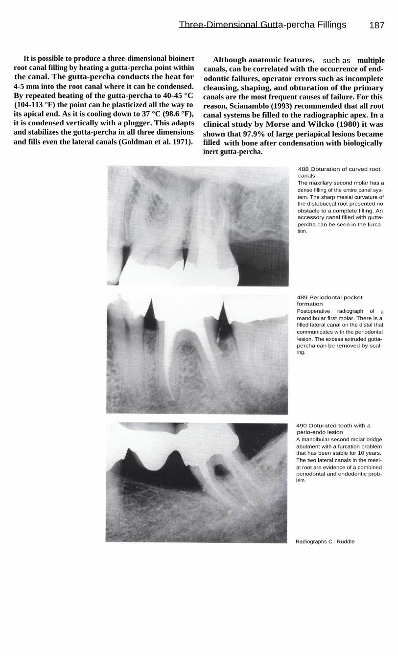
Three-Dimensional Gutta-percha Fillings 187
It is possible to produce a three-dimensional bioinertroot canal filling by heating a gutta-percha point withinthe canal. The gutta-percha conducts the heat for4-5 mm into the root canal where it can be condensed.By repeated heating of the gutta-percha to 40-45 °C(104-113 °F) the point can be plasticized all the way toits apical end. As it is cooling down to 37 °C (98.6 °F),it is condensed vertically with a plugger. This adaptsand stabilizes the gutta-percha in all three dimensionsand fills even the lateral canals (Goldman et al. 1971).
Although anatomic features, such as multiplecanals, can be correlated with the occurrence of end-odontic failures, operator errors such as incompletecleansing, shaping, and obturation of the primarycanals are the most frequent causes of failure. For thisreason, Scianamblo (1993) recommended that all rootcanal systems be filled to the radiographic apex. In aclinical study by Morse and Wilcko (1980) it wasshown that 97.9% of large periapical lesions becamefilled with bone after condensation with biologicallyinert gutta-percha.
488 Obturation of curved rootcanalsThe maxillary second molar has adense filling of the entire canal sys-tem. The sharp mesial curvature ofthe distobuccal root presented noobstacle to a complete filling. Anaccessory canal filled with gutta-percha can be seen in the furca-tion.
489 Periodontal pocketformationPostoperative radiograph of amandibular first molar. There is afilled lateral canal on the distal thatcommunicates with the periodontall esion. The excess extruded gutta-percha can be removed by scal-i ng.
490 Obturated tooth with aperio-endo lesionA mandibular second molar bridgeabutment with a furcation problemthat has been stable for 10 years.The two lateral canals in the mesi-al root are evidence of a combinedperiodontal and endodontic prob-l em.
Radiographs C. Ruddle
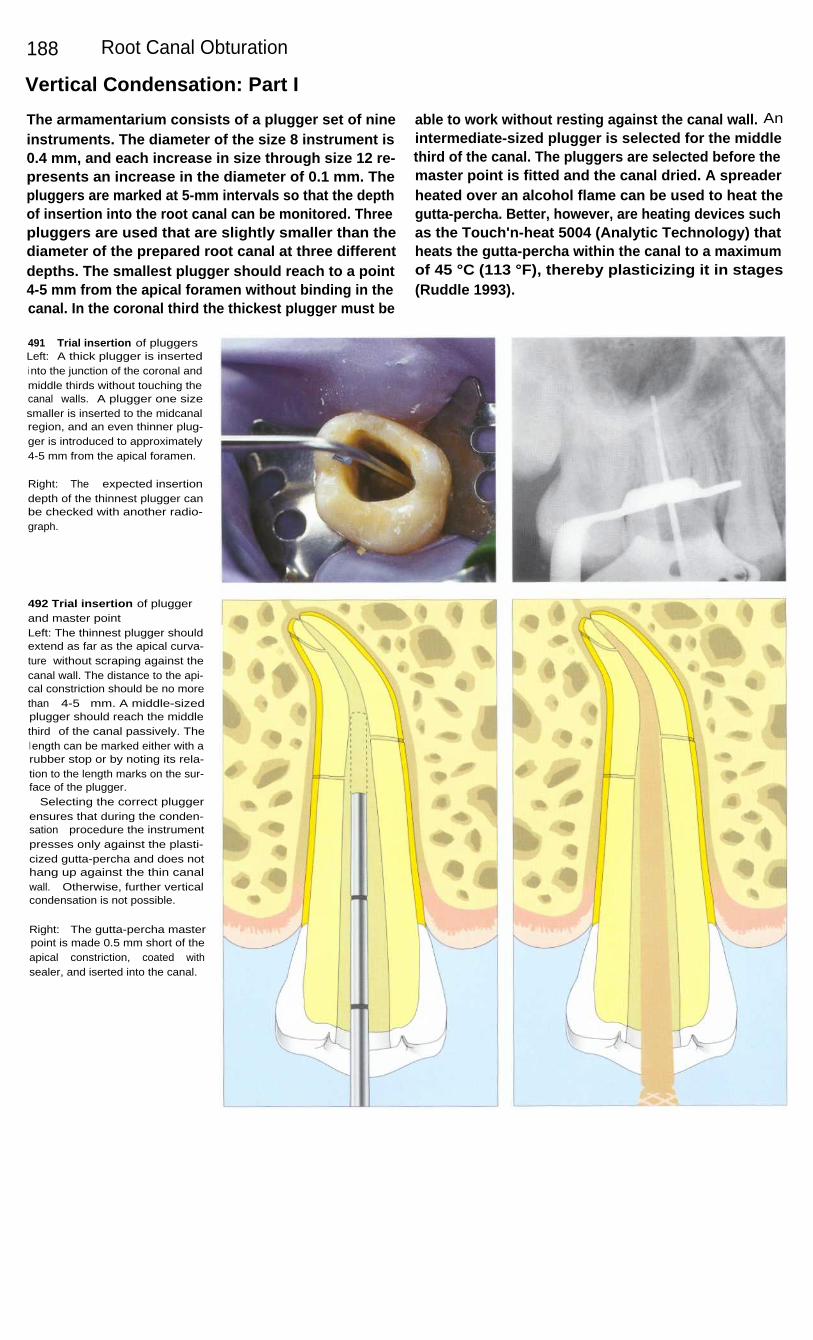
188
Root Canal Obturation
Vertical Condensation: Part I
The armamentarium consists of a plugger set of nineinstruments. The diameter of the size 8 instrument is0.4 mm, and each increase in size through size 12 re-presents an increase in the diameter of 0.1 mm. Thepluggers are marked at 5-mm intervals so that the depthof insertion into the root canal can be monitored. Threepluggers are used that are slightly smaller than thediameter of the prepared root canal at three differentdepths. The smallest plugger should reach to a point4-5 mm from the apical foramen without binding in thecanal. In the coronal third the thickest plugger must be
able to work without resting against the canal wall. Anintermediate-sized plugger is selected for the middlethird of the canal. The pluggers are selected before themaster point is fitted and the canal dried. A spreaderheated over an alcohol flame can be used to heat thegutta-percha. Better, however, are heating devices suchas the Touch'n-heat 5004 (Analytic Technology) thatheats the gutta-percha within the canal to a maximumof 45 °C (113 °F), thereby plasticizing it in stages(Ruddle 1993).
491
Trial insertion of pluggersLeft: A thick plugger is insertedi nto the junction of the coronal andmiddle thirds without touching thecanal walls. A plugger one sizesmaller is inserted to the midcanalregion, and an even thinner plug-ger is introduced to approximately4-5 mm from the apical foramen.
Right: The expected insertiondepth of the thinnest plugger canbe checked with another radio-graph.
492 Trial insertion of pluggerand master pointLeft: The thinnest plugger shouldextend as far as the apical curva-ture without scraping against thecanal wall. The distance to the api-cal constriction should be no morethan 4-5 mm. A middle-sizedplugger should reach the middlethird of the canal passively. Thel ength can be marked either with arubber stop or by noting its rela-tion to the length marks on the sur-face of the plugger.
Selecting the correct pluggerensures that during the conden-sation procedure the instrumentpresses only against the plasti-cized gutta-percha and does nothang up against the thin canalwall. Otherwise, further verticalcondensation is not possible.
Right: The gutta-percha masterpoint is made 0.5 mm short of theapical constriction, coated withsealer, and iserted into the canal.
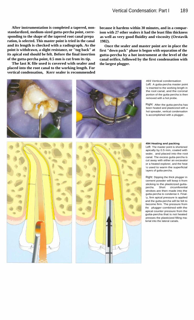
Vertical Condensation: Part I
189
After instrumentation is completed a tapered, non-standardized, medium-sized gutta-percha point, corre-sponding to the shape of the tapered root canal preparation, is selected. This master point is tried in the canaland its length is checked with a radiograph. As thepoint is withdrawn, a slight resistance, or "tug back" atits apical end should be felt. Before the final insertionof the gutta-percha point, 0.5 mm is cut from its tip.
The last K file used is covered with sealer andplaced into the root canal to the working length. Forvertical condensation, Kerr sealer is recommended
because it hardens within 30 minutes, and in a compar-ison with 27 other sealers it had the least film thicknessas well as very good fluidity and viscosity (Orstavik1982).
Once the sealer and master point are in place thefirst "down pack" phase is begun with separation of thegutta-percha by a hot instrument at the level of thecanal orifice, followed by the first condensation withthe largest plugger.
493 Vertical condensationLeft: A gutta-percha master pointi s inserted to the working length inthe root canal, and the coronalportion of the gutta-percha is thenremoved with a hot probe.
Right: After the gutta-percha hasbeen heated and plasticized with ahot spreader, vertical condensationis accomplished with a plugger.
494 Heating and packingLeft: The master point is shortenedapically by 0.5 mm, coated withsealer, and placed into the rootcanal. The excess gutta-percha iscut away with either an excavatoror a heated explorer, and the heati s used to warm the superficiall ayers of gutta-percha.
Right: Dipping the thick plugger incement powder will keep it fromsticking to the plasticized gutta-percha. Short circumferentialstrokes are then made into thegutta-percha to condense it. Final-l y, firm apical pressure is appliedand the gutta-percha will be felt tobecome firm. The pressure fromthe plugger combined with theapical counter pressure from thegutta-percha that is not heatedpresses the plasticized filling ma-terial into the lateral canals.

190
Root Canal Obturation
Vertical Condensation: Part II
After the first vertical condensation the Touch'n-heatprobe is again inserted into the gutta-percha, the heatconduction is interrupted at the handpiece, and after abrief moment the probe is withdrawn from the canal.During this procedure the metal cools and a smallamount of gutta-percha clings to the probe and is there-by removed. Now the smaller plugger can enter deeperinto the root canal and condense the heated gutta-percha. In this way gutta-percha and sealer are distrib-uted three-dimensionally over a 4-5-mm-long segmentand into any lateral canals.
During this last heating procedure, the heating probeextends to the apical region. The thinnest plugger isinserted to within 5 mm from the apical constrictionand condenses filling material into fine branches of theapical delta. In order to compensate for the thermalshrinkage, the plugger is held there with strong apical-ly directed force until the gutta-percha has cooled. Thedanger of overfilling is relatively small if the masterpoint has been shortened by 0.5 mm and fitted accu-rately to the root canal (Dagher and Yared 1993).
495 Apical condensationLeft: The surgical operationmicroscope can be focused on theroot canal from its coronal openingto its apical end, permitting in-spection of its entire length. Thecondensed gutta-percha can beseen in the apical region.
Right: After the first phase of verti-cal condensation ("down pack") iscompleted, the filled apical portionof the root canal is evaluated witha radiograph.
496 Apical condensationLeft: The heated probe is insertedto the apical region once againand pressed 3-4 mm into thegutta-percha, heating and plasti-cizing it. Upon withdrawal, theprobe removes a small amount ofgutta-percha.
Right: The smallest of the threepluggers condenses the heatedgutta-percha apically, thereby fill-i ng any lateral canals or apicalramifications. This process of heat-i ng and vertically condensing thegutta-percha is repeated three orfour times until the narrowest plug-ger reaches a point 4-5 mm fromthe previously determined workingl ength.
There is no danger of overfillingthe canal if it has been enlarged toa conical shape, the master pointhas been fitted accurately, the tem-perature does not exceed 45 °C(113 °F), and the heated probe isbrought no closer than 4 mm tothe apical foramen (Ruddle 1993).

Vertical Condensation: Part II
191
After completion of the first phase of vertical con-densation ("down pack"), a post can be inserted or therest of the canal completely filled with gutta-percha("back pack"). For the latter, a gutta-percha gun, theObtura 11, which heats the gutta-percha to 160 °C(320'F), can be employed (Yee et al. 1977). The tem-perature of the plasticized gutta-percha ranges from47'C (117 °F) to a maximum of 81 °C (178 °F) as itleaves the injection cannula. This does not damage theadjacent marginal periodontal tissue (Gutmann et al.1987 a, b).
The hot injection cannula warms the gutta-perchaalready condensed in the apical region, thereby provid-ing good adhesion to the portion of gutta-percha that ispressed into place next. The thinnest plugger is thenused to condense this 4-5-mm-long segment until it hascooled in the canal. More gutta-percha is alternatelyinjected and condensed until the root canal is complete-ly filled. Lugassi and Yee (1982) investigated howeffectively the canals of extracted teeth were sealed byvertical condensation and found that the root canal sys-tem was completely obturated when a sealer was used.
497 Coronal fillingLeft: After the apical portion of theroot canal has been filled, themore coronal portion is filled witha gutta-percha gun in the second"back packing" phase.
Right: The gutta-percha gun isbrought into direct contact with theapical filling and then gutta-per-cha, 4-5 mm long, is injected intothe canal.
498 Coronal fillingLeft: The cannula of the gutta-per-cha gun has contacted the apicalgutta-percha filling and softenedits surface. Then pressure on thecannula is gently released as asmall amount of gutta-percha isexpressed. One can feel the injec-tion cannula being pushed out ofthe root canal.
Right: The medium-sized pluggerpushes the gutta-percha apicallyand then, through circumferentialcondensation, a homogeneousfilling i s achieved. The pluggerremains in the canal until the gutta-percha has cooled. This additionalvertical condensation also fills anylateral canals that may be present.
Upon completion of the obtura-tion, its density is evaluated on aradiograph.

192
Root Canal Obturation
Clinical Results
In a clinical study by Morse et al. (1983) 458 rootcanals were filled by lateral condensation using euca-percha as a sealer. Some teeth had extensive periapicalradiolucencies. The success rate after 1 year was94.5%. Premolars, with a rate of 98.2%, were moresuccessful than molars with 92.5%. After vital extirpa-tion, failure occurred in only 1.8% of the cases,compared with a 6.7% failure rate for necrotic pulps. Ifthe root canal was underfilled the success rate was only71 %. Clinical success was recorded in almost 100% ofteeth with fillings all the way to the apical foramen.
From radiographs of 650 treated teeth, Weisz (1985)found that after 2 years 56% of the periapical bonedefects were two-thirds filled in and 40% were com-pletely filled in with new bone.
In a clinical study by Schilder (1962), 100 maxillaryanterior teeth with periapical lesions 8-35 mm in dia-meter were treated conservatively and filled with guttapercha by vertical condensation. Radiographs takenafter 6 months revealed 90-100% regeneration in 56%of the cases, and after 2 years the rate of healing was99%.
499 Down packLeft: A maxillary anterior toothserving as a bridge abutment hasa lateral radiolucency. A gutta-per-cha point has been placed into thefistulous tract. The old, inadequateroot canal filling will be replaced.
Right: A radiograph taken after thefirst phase of vertical condensationshows filled ramifications.
500 BackpackLeft: After the apical portion hasbeen filled, the coronal portion isfilled with a gutta-percha gun. Lat-eral canals, through which bacte-rial toxins presumably spread tothe lateral lesion, are now sealed.
Right: The follow-up radiograph at5 years shows complete healing ofthe lesion.
501 Apical deltaThree branches of the canal of thislower premolar have been filledduring the first phase of verticalcondensation.
Right: A radiograph of the maxil-lary incisor reveals three lateralcanals filled after the first phase ofcondensation. The remainder ofthe canal will be filled in thesecond phase using the Obtura IIsystem.

Clinical Results
193
502 Complex root canalsystemsThrough complete cleaning, shap-i ng, and vertical condensation, thecomplex root canal systems ofthese two maxillary teeth are suc-cessfully treated in a purely con-servative manner. The teeth shouldserve for a long time as bridgeabutments.
503
Root canal system andlateral lesionsRight: The 3-year follow-up radio-graph of this maxillary premolarshows regeneration of a bone lesi-on and the complex root canalanatomy with anastomoses be-tween the buccal and lingualprimary canals.
Left: Preoperatively there was anextensive lateral radiolucency onthe first premolar. A gutta-perchapoint inserted into the fistuloustract can also be seen.
504 Obturation of curvedcanalsRight: A postoperative radiographof an endodontically treated maxil-lary first molar with a slight overfillof gutta-percha. The two mesio-buccal primary canals separatenear the apex to form fourbranches.
Left: I n the mesial root of the lowersecond molar a filled lateral canalthat leads to the lesion in the bifur-cation can be seen. The canal ofthe distal root has four foramina.
505
Root canal filling andhemisectionThe lingual root of the first molarhas been amputated and themesiobuccal and distobuccal rootsare included in the fixed recon-struction. The mesial root canalhas three filled apical foramina.
Treatment C. Ruddle

194
Root Canal Obturation
Fully Automatic Method of Root Canal Preparation
The objective of endodontic treatment as a tooth-saving measure is the complete elimination of irrevers-ibly damaged and infected pulp tissue and sealing ofthe root canal system against bacterial penetration. Thecomplex anatomy of the root canal presents an obstacleto the realization of this objective. Even though goodclinical results are obtained with the previouslypresented instrumentation techniques, it is not alwayspossible to prepare and seal all the accessory canals.With a new fully automatic method the entire root
canal system can be reached, prepared, and filled(Lussi et al. 1993, Portmann and Lussi 1994, Lussi etal. 1995 c).
The biologic compatibility of endodontic irrigatingand cleaning solutions plays a dominant role in achiev-ing successful therapy (Barnes and Langeland 1966,Block et al. 1983). A 5% sodium hypochlorite solutiondissolves not only necrotic tissue but also vital pulptissue. Hence Spangberg et al. (1986) recommend amaximum concentration of I%.
506 Anatomy of the end-odontium with lateral canalsLeft: A lateral canal in the apicaregion is seen on a histologic slid(
Center: A higher magnification ofthe lateral canal with granulationtissue, cementum, and root dentin.
Right: The incomplete root canaltreatment led to pain and, ultimate-ly, to extraction of the tooth.
507
Mechanism of fullyautomatic cleaningWith pulsating pressure changes,bubbles are repeatedly formedand imploded. This process takesplace under low pressure andl eads to hydrodynamic turbulencethat in turn agitates and exchangesthe irrigating solution.
508 Schematic drawing of thecleaning apparatusA motor generates pressure oscil-l ations which create the bubbles.The storage vessel for the sodiumhypochlorite irrigating solution(left), the system of tubes, and thecontainer for the used irrigatingsolution are all designed and con-structed so that the cleaningprocess can take place undernegative pressure. This preventspassage of the cleaning solutioni nto the periapical tissue.
Right: Size comparison of thecleaning apparatus.

Fully Automatic Method of Root Canal Preparation 195
An opening is made through the crown of the tooththat is to be endodontically treated, and the interior ofthe tooth is isolated so that the cleansing can be carriedout under reduced pressure. Rapid pressure changesunder a partial vacuum cause bubbles to form that thenimplode (cavitation). This process takes place at up to250 times per second and produces an intense ex-change of the sodium hypochlorite cleaning solutionwithin the primary and secondary canals. The strongtissue-dissolving effect of sodium hypochlorite (Barnettet al. 1985, Baumgartner and Cuenin 1992) removes the
pulp tissue within 10-15 minutes. It is not necessary toexpose the canal orifices; it is sufficient to merelycreate an access opening into the pulp chamber.
The bubbles, which have a maximum diameter of50 pm, act to distribute the sodium hypochlorite solu-tion throughout the entire root canal system. Penetra-tion of the periodontal tissue by the solution is sup-posed to be prevented by the influx of blood at theforamina.
509
Prepared root canalsThe teeth have been sectionedlongitudinally for histologic prepa-ration and then stained.
Left: The apical delta is clearlyshown. Tissue remnants can beseen in the accessory canal on theleft.
Right: Two root canals that reuniteat the apex. Small tissue remnantsare still present there.
510
Prepared root canalsLeft: The root canal system is wellcleaned except for small tissueremnants in the apical third of theleft canal.
Right: Hard-tissue deposits (den-ticles) do not interfere with thepreparation. The bubbles that pro-duce the turbulence have a maxi-mum size of 50 pm and can stillbring about an exchange of thecleansing solution in spite of ob-structions.
511
Prepared root canalLeft: The SEM image of the toothin the picture on the right clearlyshows calcospherites with opendentinal tubules. No smear layer isvisible.
Right: A clean root canal systemwith the pulp tissue completely re-moved. The white particles wereproduced by cutting the tooth inhalf to expose the canal.
Histology by A. Lussi
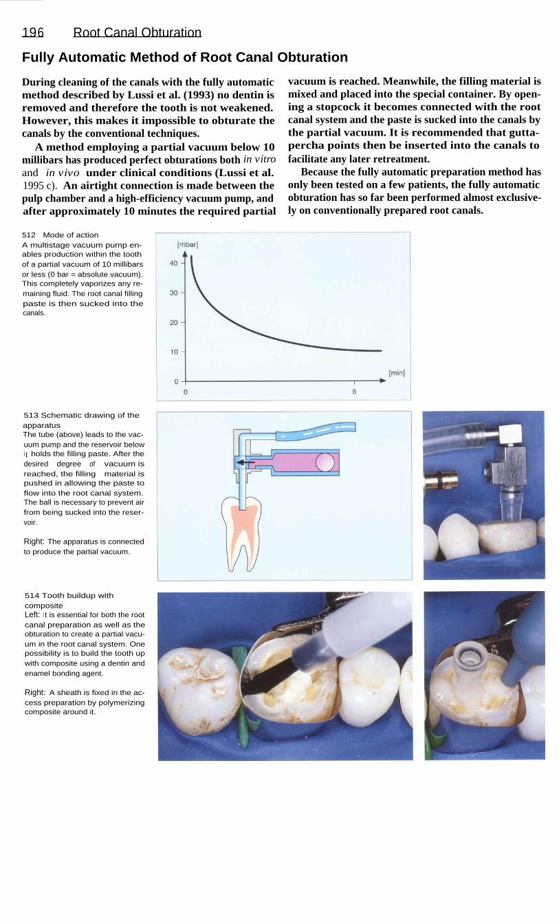
196
Root Canal Obturation
Fully Automatic Method of Root Canal Obturation
During cleaning of the canals with the fully automaticmethod described by Lussi et al. (1993) no dentin isremoved and therefore the tooth is not weakened.However, this makes it impossible to obturate thecanals by the conventional techniques.
A method employing a partial vacuum below 10millibars has produced perfect obturations both in vitroand in vivo under clinical conditions (Lussi et al.1995 c). An airtight connection is made between thepulp chamber and a high-efficiency vacuum pump, andafter approximately 10 minutes the required partial
vacuum is reached. Meanwhile, the filling material ismixed and placed into the special container. By open-ing a stopcock it becomes connected with the rootcanal system and the paste is sucked into the canals bythe partial vacuum. It is recommended that gutta-percha points then be inserted into the canals tofacilitate any later retreatment.
Because the fully automatic preparation method hasonly been tested on a few patients, the fully automaticobturation has so far been performed almost exclusive-ly on conventionally prepared root canals.
512
Mode of actionA multistage vacuum pump en-ables production within the toothof a partial vacuum of 10 millibarsor less (0 bar = absolute vacuum).This completely vaporizes any re-maining fluid. The root canal fillingpaste is then sucked into thecanals.
513 Schematic drawing of theapparatusThe tube (above) leads to the vac-uum pump and the reservoir belowi t holds the filling paste. After thedesired degree of vacuum isreached, the filling material ispushed in allowing the paste toflow into the root canal system.The ball is necessary to prevent airfrom being sucked into the reser-voir.
Right: The apparatus is connectedto produce the partial vacuum.
514 Tooth buildup withcompositeLeft: I t is essential for both the rootcanal preparation as well as theobturation to create a partial vacu-um in the root canal system. Onepossibility is to build the tooth upwith composite using a dentin andenamel bonding agent.
Right: A sheath is fixed in the ac-cess preparation by polymerizingcomposite around it.

Fully Automatic Method of Root Canal Obturation 197
515
Root canal obturationOnce the desired negative pres-sure is reached the filling paste issucked into the root canal system.To make the filling paste bubble-free, it too is subjected to a partialvacuum.
Left: The size of the sheath is se-lected according to the size of thetooth. The same sheath can beused for both cleaning and obtura-tion.
516 Filled canalsHistologic cross-section through tworoot canals. It is obvious that theanatomy of the canals was not alte-red by the cleaning process.The experimental filling paste isstained red.
Left: Two filled canals connectedby an isthmus.
517 Filled canalsThe histologic cross-section throughthe root canals shows penetrationof the root canal filling paste intothe dentinal tubules. This is possi-ble because no smear layer isformed during the cleaning proce-dure so that the pressure in thedentinal tubules is reduced as well.
Left: Dense obturation of two ovalcanals.
Collection A. Lussi
518 A clinical caseLeft: A maxillary second premolarwith a root canal instrument inplace. This was instrumented bythe Roane technique, and a cal-cium hydroxide interim dressingwas used.
Center: After obturation with thenew technique. An area of internalresorption has been filled.
Right: Additional lateral condensa-tion causes extrusion of fillingpaste into the periapical space.
Treated by B. Suter

198
Root Canal Obturation
Heated Gutta-percha
The final stage of endodontic treatment is to fill theentire root canal system and all its complex anatomicpathways completely and densely with nonirritatingagents. Total obliteration of the canal space and perfectsealing of the apical foramen at the dentin-cementumjunction and accessory canals at locations other thanthe root apex with an inert and dimensionally stablematerial are the goals for consistently successful end-odontic treatment (Nguyen 1994). Nearly 60% of end-odontic failures are apparently caused by incompleteobliteration of the canal system (Dow and Ingle 1955).
Complete filling of the root canal system in threedimensions prevents microleakage and reinfection andcreates a favorable biologic environment for tissuehealing. Over the years numerous methods and tech-niques of root canal obturation have been advocated,each with their own claims of ease, efficiency, orsuperiority. Four basic obturation techniques exist: thecold compaction of gutta-percha (1), softened and coldcompacted gutta-percha (2), thermoplasticized gutta-percha that has been injected and cold compacted (3)(Gutmann 1998).
519 Cleaning and shapingLeft: The success of endodonticcanal obturation is dependent onthe excellence of the cavity designand on thorough canal shapingand cleaning.
Right: Regardless of the methodemployed to obturate the canal, in-tensive efforts must be made to-ward obtaining total debridementand complete patency of the com-plex root canal system.
520 ArmamentariumLeft: Heat source: analytic Technol-ogy has developed several heatingunits designed to thermosoftengutta-percha (System B, 5004Touch 'n unit).
Right: Gutta-percha gun: followingthe down-packing and corking ofthe apical third, the most efficientway to back the root canal systemi s to use the Obtura II gun (Tex-ceed, California). I t uniformelysqeezes off heated aliquots ofgutta-percha against the corkedapex.
521 FillingLeft: Down-packing: following seal-er placement and gutta-percha-cone insertion, the heat carrier(and plugger) is activated. Thanthe same carrier-plugger is used tovertically pack the thermosoftenedgutta-percha apically.
Right: Back-packing: the hot andprecurved needle of the Obtura IIis inserted into the root canal, andcontrolled 4-5 mm segments ofthermosoftened gutta-percha arei njected against the previouslycorked apical third.

199
Endodontics in the Deciduous and Mixed Dentitions
Early loss of deciduous teeth can have an unfavorable effect upon the permanent dentition and theentire masticatory system. The majority of children today have little or no caries, and only in asmall minority is the caries index high. In order to maximize the effectiveness of preventivemeasures, the dentist has a duty to determine the patient's caries risk and to introduce an effective,individualized preventive program and early treatment. The same treatment concept is notindicated for all patients. Placing a patient in the "high caries risk" category remains a differen-tial diagnostic procedure specific to the patient and the conditions in which various individualfindings must be combined (Axelsson 1989, Lutz et al. 1990.)
The endodontic treatment of children and adolescents deserves special attention for manyreasons. For one thing, the psyche of the child must be considered. For another, the deciduousteeth have anatomic characteristics, such as thin dentin mantles and large pulp chambers that aredifferent from those of the permanent teeth. A basic prerequisite for successful therapy, moreover,is the cooperation of the young patient. The possibly limited benefit of endodontically treating adeciduous tooth must be weighed against the burden that will be placed upon the child. Merelyopening the tooth can be substituted as a compromise treatment for acute symptoms, but in thelong term it leaves an opening for bacteria, and is also an unsatisfactory solution insofar asmotivating the patient toward good oral hygiene is concerned (Staehle 1993).
The most important indications for endodontic treatment of deciduous teeth are traumaticinjury to the pulp of a vital tooth, carious pulp exposure, and symptoms of pulpitis. Contra-indications are a severely damaged or nonrestorable crown, resorption of more than half of theroot length, pronounced resorption of interradicular or periapical bone and a high degree of toothmobility, a severely neglected dentition, severe systemic disease, and insufficient cooperation bythe child (Leisebach et al. 1993).
Endodontic treatment in the deciduous dentition encompasses treatment of dentin near the pulpwithout opening into the pulp (indirect pulp cap), direct capping of the exposed pulp, pulpotomy(amputation of the coronal portion of the pulp), and pulpectomy followed by filling of the rootcanals with resorbable materials.
The main objective of endodontic treatment of a permanent tooth with incomplete root growthis to maintain its vitality and allow completion of root growth. Where the apical foramen is wideopen, conventional root canal treatment can be accomplished only under certain circumstances.In addition to direct pulp capping and pulpotomy, the therapeutic steps that may be requiredinclude apexification if the pulp tissue is necrotic, followed by root canal filling (Lenhard andStaehle 1996).

200
Endodontics in the Deciduous and Mixed Dentitions
Pulpotomy in the Deciduous Dentition
Pulpotomy means the complete amputation of thecoronal pulp down to the orifice of the root canal. Thespecial indication is an exposed pulp in a tooth that isvital. In deciduous teeth, pulpotomy is preferable todirect pulp capping. Contraindications are clinicalsymptoms such as pain, swelling, tenderness to percus-sion, fistulation, and abnormal tooth mobility. Radio-graphic contraindications are changes such as internaland severe external resorption, as well as periapicaland interradicular lesions (Staehle 1993).
When the pulp tissue is vital and exposed the pulp-otomy should be performed under local anesthesia. Thecoronal pulp tissue is removed with a high-speed dia-mond stone under irrigation with isotonic saline solu-tion. In this way the bleeding can best be controlled.After the pulp chamber has been cleared of all softtissue and irrigated with saline, bleeding is stopped byapplying pressure with a sterile cotton pellet. A pulpcapping material is then placed and the coronal cavityis tightly sealed with a restoration.
522 Tooth fractureA maxillary deciduous canine withl oss of a large part of the crownand pinpoint exposure of the pulp.The tooth is asymptomatic, gives apositive response to the sensitivitytest, and is not tender to percus-sion. There is no fistual or palpableswelling. A pulpotomy will be per-formed under local anesthesia.
523 Pulp amputationLeft: The coronal pulp tissue isremoved with a diamond burturning at high speed, and the pulpchamber is cleaned of all tissue,remnants and irrigated with iso-tonic saline solution.
Right: Vital pulp tissue is severedcleanly at the level of the rootcanal orifice under constant irriga-tion with sterile saline solution.
524 HemostasisA sterile cotton pellet is pressedagainst the remaining pulp tissueand changed several times until thebleeding has completely stopped.If hemostasis cannot be achieved,severely inflamed pulp tissue maybe present. In this case a pulpo-tomy is no longer indicated (Leise-bach et al. 1993).

After placement of calcium hydroxide, deciduousteeth too can form a bridge of hard tissue. If hemostasisis inadequate, a coagulum forms that will inducechronic inflammation and subsequent internal rootresorption (Schroder 1985).
Clinical studies indicate a success rate of 31-100%of cases treated (Schroder 1978, Heilig 1984). Histo-logically, however, only 50% show a dentinal bridgeand healing while the rest show inflammation andinternal resorption (Doyle et al. 1962).
Pulpotomy in the Deciduous Dentition 201
Even today formocresol, a mixture containing 19%formaldehyde and 35% cresol, is still used in de-ciduous teeth. A 5-minute application leads to super-ficial fixation, bordered by vital, but chronically in-flamed pulp tissue. Pure zinc oxide-eugenol should beplaced on the remaining tissue and the cavity is thenfilled. In spite of the 94-98% clinical success rate(Verco et al. 1984, Hicks et al. 1986), the distributionof the chemicals throughout the system is an argumentagainst their use in deciduous teeth (Araki et al. 1993).
525 FormocresolA cotton pellet moistened withformocresol is applied against theexposed pulp tissue for 5 minutes.
Left: Formocresol must be broughti nto direct contact with the pulptissue for fixation to occur. Theunderlying tissue then becomespartially necrotic and infiltratedwith leukocytes.
526 Tissue reactionThe pulp tissue has a brownishcolor after removal of the cottonpellet. In spite of removal of theexcess formocresol, a systemic dis-tribution reaching the periodontalli gament, bone, liver, kidneys, andl ungs has been shown in animalexperiments (Pashley et al. 1980).Toxic effects can be avoided, how-ever, by using a concentration ofno more than 0.38 pM (Ranly 1985,1 987).
527 Coronal restorationOnly those endodontically treateddeciduous teeth that are restoredwith crowns will be long-term clini-cal successes.
The mutagenic and carcinogenicpotential of formocresol makes theuse of this type of therapy in de-ciduous teeth questionable (Gold-macher and Thilly 1983, Friedberget al. 1990).
Left: Pure zinc oxide-eugenol ce-ment is placed over the points ofamputation. This is covered withglass ionomer cement, then a pre-fabricated crown is inserted.

202
Endodontics in the Deciduous and Mixed Dentitions
Pulpectomy in the Deciduous Dentition
Root canal treatment of a deciduous tooth is indicatedwhen irreversible pulpitis or pulpal necrosis is present.Contraindications are an unrestorable tooth, radio-graphically visible internal resorption, carious ormechanical perforation of the floor of the pulpchamber, extensive pathologic resorption of more thanone-third of the root, bone resorption with furcationinvolvement, and a well-delineated periapical lesion. Ifthese cases are excluded, pulpectomy can have asuccess rate of 90% (Camp 1994).
In the anterior region the access opening is made on
528 Canal instrumentationLeft: With a rubber dam in placethe deciduous tooth is opened foraccess and the coronal pulp is re-moved. The floor of the pulp cham-ber is thinner than in permanentteeth, therefore the danger of per-foration is greater.
Right: The expected workingl ength is verified on a diagnosticradiograph. Then the canal is care-fully enlarged to the workinglength, 2-3 mm short of the apex.
529 Canal fillingLeft: Zinc oxide-eugenol withoutadditives is applied over the cavityfloor in a creamy consistency andpressed into the root canals with asterile cotton pellet.
Right: A plugger with the workingl ength marked is used to slowlypack the cement into the canalwithout overfilling it.
530 Radiographic monitoringRadiographs are taken immediate-ly after treatment and at 1 year and2 years afterward to evaluate thesuccess of the treatment, normalroot resorption, and resorption ofthe filling material. In a controlled2-year study on 1363 endodon-tically treated deciduous teeth,there were only seven failures. Therisk of damage to the tooth germ ofthe succedaneous tooth was nohigher than with formocresol pulp-otomies (Rabinowicz 1953).
the lingual, and in the posterior region the thin dentinat the floor of the pulp chamber must be considered.The canals are prepared with prebent hand instrumentsto a depth 2-3 mm shorter than the radiographic length.Care must be taken not to perforate the thin walls. Be-cause the apical ramifications cannot be instrumentedmechanically, they must be generously irrigated withsodium hypochlorite solution. In necrotic teeth thecanals of the unanesthetized tooth are filled with re-sorbable zinc oxide-eugenol without additives and thecrown of the tooth is restored (Goerig and Camp 1983).

Direct Pulp Cap
Direct capping of a permanent tooth with incompleteroot development means covering the exposed pulpwith a wound dressing that will induce formation ofnew hard tissue. The potential for regeneration is at itshighest if the pulp tissue is not inflamed at the begin-ning of treatment (Heys et al. 1985). If there is bacteri-al contamination due to caries or through contact withsaliva for more than 24 hours, treatment success cannotnormally be expected. It is also very important that therestoration provide a bacteria-tight seal (Cox and Ber-genholtz 1982).
Direct Pulp Cap
203
The greatest release of calcium ions, and thereforethe greatest stimulus for hard-tissue formation, isprovided by aqueous calcium hydroxide preparations(Schubich et al. 1978). However, the calcium necessaryfor a dentinal bridge is available from the body's owntissue (Pisanti and Sciaky 1964). Beneath the zone oftissue necrosis induced by the calcium hydroxide,differentiation of secondary odontoblasts takes place,and irregular osteodentin or tubular tertiary dentin isformed (Schr6der and Granath 1971, Fitzgerald 1979,Schr6der 1985).
531
Uncovering the pulpA pulp that does not appear in-flamed when it is uncovered duringthe access preparation has a highpotential for regeneration. Bleed-i ng is arrested with a sterile cottonpellet. If a blood clot forms be-tween the pulp and the cappingmaterial, the probability of healingis reduced by about 50% (Schr6-der 1973). In teeth with incompleteroot growth the prognosis is quitegood, but the chance of successdeclines with increasing age (Hor-sted et al. 1985).
532 Pulp cappingAqueous calcium hydroxide isthinly applied and gently con-densed with a sterile cotton pellet.Then it is observed for possibleoozing of blood. If blood appears,the capping material must beflushed out, hemostasis must beachieved, and new capping mate-rial applied. The paste form ofcalcium hydroxide is substantiallysuperior to cements because itsrate of ion release is twice as high( DeFritas 1982).
533 RestorationOnce again, a prerequisite for suc-cessful treatment is a perfectlysealed coronal restoration. Ifbacteria penetrate through theocclusal filling, inflammation willdevelop and the pulp tissue willbecome necrotic. The calciumhydroxide is covered with zincoxide-eugenol, which in turn canbe covered with either zinc phos-phate or glass ionomer cement; arestoration is then placed.

204
Endodontics in the Deciduous and Mixed Dentitions
Pulpotomy in the Mixed Dentition
The indication for a pulpotomy on an asymptomaticpermanent tooth with incomplete root development is awide pulp exposure with or without inflammationlimited to the coronal pulp. Pulp amputation is of aninterim nature. Besides formation of a hard-tissuebridge, islets of tertiary dentin are formed after4 months that can almost completely obliterate the rootcanal. After the completion of root development, rootcanal treatment should be performed even if the toothis asymptomatic (Subay et al. 1995).
534 Caries progressionThe bitewing radiograph in the leftposterior region of a 13-year-oldgirl reveals deep caries on the me-sial surface of the lower first molar.There have been no clinical sym-ptoms as yet. Carious lesions canalso be seen on the maxillarysecond premolar and first molar.
535 Access openingAn extensive opening into the pulpchamber is created during excava-tion of caries. As an interim treat-ment the coronal pulp tissue is re-moved, and only after completionof root growth is root canal treat-ment performed.
Right: A high-speed diamond buris used to remove the coronal pulptissue down to the level of thecanal orifices.
536 Root developmentBefore root canal treatment isbegun, a radiograph is taken todetermine the stage of root devel-opment. If root growth has pro-gressed sufficiently the pulpotomyi s viewed only as an interim mea-sure until the roots have complete-ly developed. Deposition of hardtissue can lead to blockage of theroot canals and complicate latercanal instrumentaion.
The goal of a pulpotomy is to maintain the vitalityof the pulp in the root canal for a limited period of timeso that further root development with the formation ofan apical constriction can take place (Magnusson1981). Under anesthesia the coronal pulp is removedwith a high-speed diamond bur, the cavity is rinsedwith isotonic saline solution, and a sterile cotton pelletis pressed over the entrances to the root canals forhemostasis. A blood clot between the capping mediumand the remaining pulp will delay or prevent theformation of a hard-tissue bridge (Masterton 1966).

Calcium hydroxide is applied thinly and the cavity is
checked for any oozing of blood. Then the layer is built
up to a thickness of 2 mm and covered with IRM and
glass ionomer cement. Calcium hydroxide is thematerial of choice for pulp capping in young perma-
nent teeth. When mixed with tricalcium phosphate it
induces hard-tissue formation without the initial de-
struction of the adjacent pulp tissue that is typical of
pure calcium hydroxide (Yoshiba et al. 1994). Heretoo, a tight coronal seal appears to be just as important
for success (Snuggs et al. 1993).
Pulpotomy in the Mixed Dentition
205
At regular recall appointments every 3-6 months the
treatment result is evaluated clinically and root
development is monitored radiographically. Sensitivity
tests on teeth with pulpotomies are of little value (Lei-
senbach et al. 1993). In a clinical investigation on 37
permanent teeth, 93.5% of the cases were successfulwith no clinical or radiographic evidence of disease.
Furthermore, pulpotomy achieved the desired objective
even in many cases of symptomatic teeth with peri-
apical lesions (Mejare et al. 1993).
537 Pulp capping materialCalcium hydroxide in an aqueoussuspension is applied as a thinl ayer over the pulp stump. A visualinspection then ensures that thereis no seepage of blood. Next, thelayer is built up to a thickness of1-2 mm and the coronal cavity istightly sealed.
Left: Before the capping materialis applied, complete hemostasis isachieved through pressure withsterile cotton pellets.
538 Root canal instrumenta-tionIf symptoms recur after the pulp-otomy, the amputation is expandedto an apexification procedure be-cause, with irreversible pulpitis, thepulp must be removed. If, on theother hand, no symptoms appear,root canal treatment is delayeduntil after completion of root deve-l opment. The tooth i s thenanesthetized, the working lengthdetermined with a radiograph, andthe root canals completely instru-mented.
539
Root canal obturationAfter treatment with an interimdressing, the canals are obturatedwith gutta-percha and a eugenol-free sealer. Then an adhesivebonding agent is used to seal thecavity and the tooth is prepared fora partial veneer crown.
Left: Before the canals are filled,gutta-percha points correspondingto the sizes of the AMFs are select-ed and their fit in the canalschecked by a master point radio-graph.

206
Endodontics in the Deciduous and Mixed Dentitions
Teeth with Developmental Defects
Dens Invaginatus
This developmental defect results from the invagina-tion of the mineralized part of the crown: the root mayalso be included. The incidence of such a dens in dentecan be as high as 10% of both deciduous and perma-nent teeth. It is most frequently found on maxillarylateral incisors. A dens in dente usually occurs with aconical crown and an enlarged root canal. An enlargedcrown and either a normal-sized or enlarged root canalso occur (Bimstein and Shteyer 1976). Pulpal necro-
540 Abscess formationA vestibular submucosal abscessat the level of the root tip of the lat-eral incisor. After drainage of theaccumulated pus the incision isi rrigated for 5 days and kept openby means of a rubber drain.
541 InstrumentationLeft: The radiograph shows an ab-normality in the coronal region thati ndicates a dens invaginatus. Acherry-sized periapical radiolucen-cy can also be seen.
Center: After the tooth is opened,a wider than usual access prepa-ration i s made through whichpieces of the invagination havealready been removed.
Right: The root canal is preparedto the working length with files.
542 CleansingThe root canal is cleaned withhand instruments. Because of thei rregular canal morphology, tissueremains behind. This has to beloosened and flushed out withgenerous and frequent sodiumhypochlorite irrigations.
sis can develop as soon as these teeth erupt into the oralcavity. The cause is bacterial invasion through thecoronal invagination. If the invagination is small, it canbe removed during preparation of the access cavity.When there is a complex invagination, instrumentationshould be carried out carefully following the anatomicform. If a dens invaginatus is diagnosed early, pulpalnecrosis can be prevented by sealing the coronal defect(Rotstein et al. 1992).

Lingual Groove in the Root
About 8.5% of teeth exhibit this developmental anom-aly. The most frequent location of this developmentaldefect is also on the maxillary lateral incisors. Lingualroot grooves can lead to periodontal bone resorption asa result of bacterial toxins along the groove (Whiters etal. 1981). The bone defect extends as far apically as thegroove. An extension of the groove beyond the cervicalregion is associated with a poor prognosis (Lee et al.1968).
Teeth with Developmental Defects
207
Pulpal necrosis can occur as a complication whenbacteria penetrate through deep root grooves into thepulp tissue. A lingual groove in a root can be diagnosedon the radiograph as a thin, radiolucent, parapulpalline. A gutta-percha point introduced into a fistuloustract will lead to the lateral periodontal defect. Conser-vative therapy consists of laying a surgical flap andeliminating, or at least reducing, the root groove bysmoothing the root or filling the defect (Rotstein et al.1992).
543 Interim dressingCalcium hydroxide is packed intothe dried root canal with paperpoints. If the exudate is heavy thei nterim dressing is changed after 7days and again after an additional30 days.
Left: After only a few days theswelling has receded and theblood supply to the mucosa isnearly normal.
544 Apical regenerationLeft: The last interim dressing isl eft in the root canal for another3-6 months to exert its tissue-dissolving and antibacterial effects.
Right: The radiograph taken after3 months shows definite regenera-
tion of the periapical bone. Theoutline of the root canal appearsi ndistinct because of the calciumhydroxide filling.
545
Root canal obturationLeft: After the gutta-percha masterpoint is fitted and adjusted, the rootcanal is obturated with additionalgutta-percha and sealer followingthe lateral condensation technique.
Center: The radiograph taken im-mediately after placement of thefilling shows a good apical seal.
Right: The follow-up radiographafter 1.5 years.

208
Endodontics in the Deciduous and Mixed Dentitions
Apexification
The indication for an apexification procedure on atooth with incomplete root development and eitherwith or without clinical and radiographic symptoms ispulpal necrosis. Further root development in a necrotictooth is unlikely. The walls of the root canal divergeapically, preventing the preparation of an apical stop.Treatment is therefore directed at inducing the forma-tion of a hard-tissue buttress than can help preventoverfilling of the canal. The material best suited to thispurpose appears to be calcium hydroxide (Heithersay1975).
546 Pulpal necrosisLeft: This maxillary right centrali ncisor of a 14-year-old girl isasymptomatic but has a vestibularfistula and an enamel defect that ispresumably of traumatic origin.
Center: The radiograph shows thetooth to have a periapical lesionand an apical foramen that, incomparison with the adjacenttooth, is wide open.
Right: The working length is set 2mm shorter than the length of thetooth as measured on the firstradiograph.
547 Root canal dressingFor a vital amputation (left) thepulp tissue (1) is covered with cal-cium hydroxide (2), glass ionomercement (7), and composite (8), anda dentinal bridge (5) is formed.
For apexification (center) onthe other hand, the entire rootcanal is filled with calcium hydrox-ide (2), and the coronal cavity issealed with ZnOE (3) and a denseprovisional filling (4).
After a period of no less than9 months (right) a hard-tissuebridge (5) will have formed at theapex and the canal can be filledwith gutta-percha (6).
548 Monitoring progressLeft: After careful instrumentation,the root canal is filled with calciumhydroxide. Because of its resorp-tion by periapical inflammation, thedressing has to be changed initial-l y every 4 weeks.
Right: After 20 months the dress-i ng is removed and the root canalfilled with gutta-percha. The radio-graph shows healing of the peri-apical lesion and a hard-tissuebridge.
The working length is set 2 mm shorter than normalto avoid overinstrumentation. Also, because of the thindentinal walls, the canal must not be widened exces-sively, and thus must be irrigated generously. If rootcanals with open apices are filled for 3 months withCalasept and if the dressing is changed every 4 weeks,the periapical radiolucency will regenerate with theformation of cementoid hard tissue. When the rootcanals are not filled with calcium hydroxide, theinflammation persists and an apical seal cannot beachieved (Leonardo et al. 1993).

Retreatment of Endodontic Failures
Endodontic failure following insufficient instrumentation and removal of microbial infections orinadequate obturation is often ultimately due either to carelessness of the operator, a misunder-standing of the treatment concepts, or the use of toxic materials. It could also be traced back toinadequate familiarity with root canal anatomy or failure to follow complex root canal systems(Scianamblo 1993). Reasons for retreatment include failure because of a root canal filling that istoo short, a significantly overfilled or underfilled root canal, or a perforation. A distinction ismade between retreatments of teeth without clinical symptoms or radiographic changes andretreatments in the presence of clinical symptoms and/or radiographic lesions. Retreatment isindicated with symptoms such as fistulation, swelling, pain, percussion tenderness, discomfortduring chewing, and in cases in which the apical lesion becomes larger or is not diminishing. Inthese cases there is chronic apical inflammation and persistence of the periapical radiolucency.Such failures are most common with paste fillings that not only fail to seal the root canalsufficiently, but are also resorbed to a greater or lesser extent over time. Retreatment of aninadequate root canal filling should eliminate the infection and prevent reinfection (Beer andBaumann 1994 a).
209
549
I nadequate root canalfillingA A paste filling that contains
formaldehyde in an incomplete-ly instrumented root canal. Thereis periapical accumulation of in-flammatory cells.
B A poorly adapted filling withvoids is visible at higher magni-fication.
C An even greater magnificationshows remnants of fixed pulptissue at the end of the pastefilling.
D The periapical region showssigns of inflammation.
E Particles of filling material aredistributed throughout the tis-sue and have attracted clustersof foreign-body giant cells andneutrophilic granulocytes.

210
Retreatment of Endodontic Failures
Failures and Root Canal Anatomy
Overlooked primary canals or apical ramifications arethe most common causes of endodontic failure. About40% of all mandibular incisors have two root canals,whereas two apical foramina are found in only 1%.During retreatment, both orthoradial and eccentricradiographs must be taken to better reveal anatomicvariations. Eighty-four percent of all maxillary firstpremolars and 58% of all maxillary second premolarshave a second root canal. Furthermore, 8% of the firstpremolars have three or more primary ramifications(Vertucci 1974).
550 Overlooked canalI n the access preparation of a max-i llary second premolar, one filledcanal and a second unfilled canalare found. Since completion of thefirst endodontic treatment thepatient has been complaining ofsevere spontaneous pain, but thisdid not lead the dentist who placedthe filling redoing the treatment.
551 Periapical radiolucencyLeft: A periapical radiolucencyand root canal filling, which ap-pears to be successful, can beseen in the diagnostic radiograph.The filling however, does not ex-tend into the apical curvature.
Right: The working-length radio-graph shows a patent secondcanal. The length is adjusted be-fore further instrumentation.
552 InstrumentationThe second canal is completelyinstrumented all the way to theapical constriction. It is decided toleave the filling in the first canal inplace, because on the radiographit appears to be well adapted.
Right: Calcium hydroxide ispacked firmly into the root canaland the cavity is then sealed with abonded restoration.
During embryonic development the mesiobuccaland mesiolingual root canals of the maxillary firstmolar originally have one primary canal each. Asdevelopment progresses, the tendency to invaginationand deposition of hard tissue arises so that the canal inthe lingual portion of the mesiobuccal root is reducedand becomes partially or completely obliterated (Pine-da 1973). When a failure occurs in a maxillary molar,failure to instrument and treat one or more canals orforamina is the probable cause.

Failures and Root Canal Anatomy
211
Mandibular premolars have the most complex rootcanal system. DeDeus et al. (1975) discovered twoprimary ramifications in approximately 31% of firstpremolars and 11 % of second premolars; 3% even hada third main canal. The root canals must be probed witha fine prebent size 08 file. Here the file is advancedalong the outer wall of the first canal located untilresistance or a branching is felt. The additional canal isthen made fully accessible through gentle rotatingmovements (Scianamblo 1993).
Secondary and tertiary ramifications as lateral oraccessory canals are branches of the primary root canalthat open into the periodontal space. More than 20% ofall anterior teeth and 50% of posterior teeth havemultiple ramifications (Burch and Hulen 1974). Thesebranches are difficult to find with instruments, but canbe cleaned effectively by copious irrigation withsodium hypochlorite. During reinstrumentation theyusually become closed by paste or dentin shavings sothat not all tissue can be completely removed(Scianamblo 1993).
553 Canal fillingThe interim dressing is flushed out3 months after it is placed, and thesecond root canal is filled withgutta-percha and sealer. The be-ginning of bone regeneration canbe seen in the area of the periapi-cal radiolucency.
554
Post and core buildupAfter an additional 2 months thecrown of the tooth is built up again.Two threaded posts (Endofix-A) areplaced passively into the preparedpost spaces, and their positionsare checked with a radiograph.
Left: Threads are cut into the postspaces and the posts are theni nserted with polycarboxylate ce-ment.
555 Crown restorationOne year after the beginning ofendodontic retreatment the peri-apical radiolucency has completelyhealed and the tooth is restoredwith a full coverage crown. The rootcanal treatment is not consideredcomplete until the definitive resto-ration is placed.
Left: Before the artificial crown ismade, the tooth is built up with abonded composite restoration,then the crown preparation is cut.

212
Retreatment of Endodontic Failures
I ndications for Retreatment
The primary cause of endodontic failure is bacteriaremaining in the root canal system. Grossman (1972)classified the causes as: (1) incorrect diagnosis, (2)poor prognosis, (3) technical difficulties, and (4)careless treatment. In the Washington study (Ingle1985) the primary cause of 76% of the failures wastreatment error, such as incompletely filled canals,unfilled canals, perforations, severe overfilling, andbroken instruments. Poor case selection was respon-sible for 22% of the failures.
Nair et al. (1990a) conducted a study with opticaland electron microscopes to determine the cause oftherapy-resistant periapical lesions associated withasymptomatic teeth. Within a time span of 4-10 years10% of the endodontically treated teeth required surgi-cal retreatment. Six out of nine biopsies revealedmicroorganisms in untreated apical sections of the rootcanals and four of these contained multiple bacterialspecies. In other cases without evidence of bacteria,giant cell granulomas were present as foreign-bodyreactions to the filling material.
556 Prosthetic treatmentThis pretreatment bitewing radio-graph of the right posterior regionof a 41-year-old patient shows in-adequate crowns and fillings withoverhanging margins, as well asrecurrent caries on the lowersecond premolar and first molar.The first molar exhibits no clinicalsymptoms and presumably end-odontic treatment had beenattempted earlier, as evidenced bythe remnants of root canal fillingmaterial found in the canals.
557 Access preparationWhen the access opening is madethrough the crown, carious de-struction of the hard structures isfound. All carious dentin is remov-ed to the level of the canal orificesand these are then probed.
Right: To prevent penetration ofthe root canals by saliva andmicroorganisms between appoint-ments. Cavit is placed in the cavityand condensed.
558 InstrumentationThe partially obliterated rootcanals are carefully probed withthin files and their locations veri-fied with a first radiograph.
Right: Copious i rrigation with sodi-um hypochlorite loosens tissueremnants and helps to overcomeobstructions.

I ndications for Retreatment
21 3
Indications for retreatment of endodontically treatedteeth are periapical radiolucencies that have not de-creased in size after 4 years, and newly formed peri-apical radiolucencies. Further indications are exclusive-ly clinical symptoms such as tenderness to percussion,apical pain as a response to pressure, fistula formation,and swelling of the soft tissues, all of which are indica-tions of apical periodontitis. Incomplete root canal fill-ings must be replaced before prosthodontic treatment,even if the teeth are asymptomatic. The same is true ofroot canal fillings that have been exposed to the oral
environment for any length of time. Neglecting to takeadequate radiographs can also lead to treatment failuresin endodontia. The dentist cannot plead that the patientdid not wish, or refused, to have radiographs takenwhen they were necessary for diagnostic purposes orfor selection of appropriate treatment (Hulsmann1995). According to Gunther (1967), the radiograph isindispensable for reviewing and complementing theclinical diagnosis, monitoring the progress of the rootcanal treatment, evaluating the filling, and for makingthe final restoration.
559 InstrumentationAfter the initial uncovering and en-l argement of the coronal segmentsof the root canals, a second radio-graph is taken to determine theworking length.
Left: The root canals are enlargedby four sizes to the apical constric-tion. The AMF is size 35.
560 Canal obturationAt the second appointment at least4 weeks later, the asymptomatictooth is filled with gutta-perchaand sealer. The interim crown isthen removed and a threaded posti s inserted into the distal canal.
Left: Gutta-percha points are fittedto evaluate the adequacy of thecanal enlargement. The mesiobuc-cal canal preparation has to belengthened by an additional 1 mm.
561 Artificial crownA core buildup is placed, the toothis prepared for a crown, and animpression is made for a full goldcrown. The fillings in the adjacentteeth are replaced or recontouredas needed. This radiograph taken3 years after root canal treatmentshows no indication of periapicalinflammation.

214
Retreatment of Endodontic Failures
Pain Following Root Canal Treatment
Within hours or a few days, pain in combination withswelling can appear. In the investigation by Walton andFuad (1992), pain occurred in only 32% of 946 end-odontically treated teeth. Pain was associated with anecrotic pulp in 6.5% of the cases, and with irreversiblepulpitis in only 1.3%. Nineteen percent of cases withsevere pain present at the beginning of treatment alsoexperienced postoperative problems, but postend-odontic problems occurred in only 1.7% of cases withslight initial pain.
In the study by Lin et al. (1991) more than half of150 failures were not associated with clinical symp-toms. Pain was present in only one-fourth of the cases.In two-thirds of the teeth bacteria were found, and theseverity of the inflammation was correlated with thepresence of bacteria in the canal. Bacteria were foundin 80% of teeth with pain as the only symptom, and in75% of teeth with swelling as the only symptom. Paincombined with swelling occurred only in the simulta-neous presence of bacteria, and bacteria were respon-sible for the formation of 84.6% of fistulas.
562 Postoperative painLeft: The mandibular first molarhad four canals endodonticallytreated and filled. In spite of this,the severe pain that was presentbefore treatment persisted.
Right: The crown and root canalfilling are removed and the rootcanals retreated. The canals aretemporarily filled with a predniso-l one-antibiotic mixture (Ledermix)to relieve the pain.
563 InstrumentationLeft: Due to persisting pain thei nterim dressing is removed andthe canals are filled with a calciumhydroxide paste.
Right: The dressing is removedagain within 1 week because thepatient described the pain asalmost unbearable.
564 Alleviation of painLeft: Due to persisting pain the sec-ond molar is also endodonticallytreated. This radiograph deter-mines the working length.
Right: After the interim dressingwas placed in the canals and thetooth was closed once again, thepatient was free of pain.
Pain Following Root Canal Treatment 215
Of all the parameters investigated in another study,only the following three were related to the occurrenceof postoperative pain: pain at the beginning of treat-ment, anxiety before treatment, and certain medica-tions administered after the endodontic procedure.When postoperative pain was mild, no difference wasfound between the placebo and a specified medication.However, when the pain was severe, ibuprofen andespecially erythromycin and penicillin were signifi-cantly more effective than a placebo (Torabinejad et al.
1 994).
The type and manner of instrumentation of the rootcanal and the extrusion of potentially infected dentinshavings into the pulp tissue favored the occurrence ofpostoperative pain (Bystrom and Sundqvist 1985). Theroot canal anatomy, however, can also influence thepostoperative results. In histologic sections of rootcanals that were C-shaped in cross-section (occurringin 13.9% of all molars), the amount of debris remainingand the portions of uninstrumented canal walls wereespecially noticeable, especially in the middle andapical thirds (Simon 1993 a).
565
Root canal obturationAfter the patient was free of painfor 4 weeks the root canals werefilled. This radiograph shows thefitted gutta-percha master points inboth teeth.
566
Root canal obturationA bacteria-impervious obturationof the seven root canals is accom-plished by lateral condensation,and the coronal openings of bothteeth are then sealed.
567 Freedom from painThe follow-up radiograph taken 2years after treatment shows normalperiapical bone structure. The pa-tient has been completely free ofpain since both teeth were end-odontically treated.

216
Retreatment of Endodontic Failures
Removal of Post-Cores
If the tooth has been treated with a post-core and crown,these should be removed before the tooth is retreated.Once the artificial crown has been removed, the toothanatomy can be better verified and a better access prep-aration can therefore be made. With the restorationremoved, it is easier to evaluate the diagnostic radio-graph in regard to perforations and the length of a silverpoint or other obstruction in the region of the canalorifices. A vertical fracture and the extent of cariousdemineralization can also be better evaluated with thecrown removed (Stabholz and Friedman 1988).
The preparation for a post-core weakens the toothstructure. When such a restoration must be removedthere is a risk of tooth fracture. The removal of a screwpost is usually less dangerous, with the risk rising indirect proportion to the increase in contact area. Ultra-sound weakens the adhesion to the canal wall andgreatly simplifies removal of the post. Cement rem-nants must be broken up with a sharp ultrasonic scalerbefore the post is loosened. Use of diamond or carbidesteel burs is contraindicated.
568
Pain as an indication forretreatmentThe mandibular first molar had anartificial crown, a post-core, and aroot canal filling that was too short.I ntermittent pain led to the deci-sion to repeat the 2-year-old end-odontic treatment, even thoughthere were no radiographic signsof pathology.
569
Removal of the core andthreaded postA relatively large occlusal cavity ismilled through the clinically accept-able crown and most of the corematerial is removed. All the ce-ment is then removed from aroundthe post with a sharp tapered ultra-sonic scaler.
Right: Next, a broad ultrasonic in-sert is guided around the threadedpost at a height of approximately2 mm to loosen it.
570
Locating the canal orificesAfter about 6 minutes the threadedpost became noticeably loosenedand was removed from the canalwith forceps.
Right: With the help of an operat-i ng microscope and an explorerthe floor of the cavity is inspected.No fracture line is found, but theentrance to a fourth canal isdetected next to the filled distalcanal.

Removal of Post-Cores
217
Parallel-sided paraposts were cemented with zinc-phosphate cement in preparations 4 mm deep withinroot canals. By using an ultrasonic device it waspossible to loosen them within 8 minutes and thenremove them with a Luer forceps, using a force ofapproximately 1 kg. Scalers vibrating in the sonicrange, on the other hand, were unable to even partiallyloosen the posts within 60 minutes, and therefore arenot indicated as an aid to post removal (Buoncristianiet al. 1994).
A very effective method for removing post-and-cores is by using the Gonon post remover. After thepost-core has been removed, the canal orifices must belocated, preferably with the help of magnifying loupesor an operating microscope. At this time the floor of thecavity should be examined visually for fracture linesthat would indicate that a vertical fracture had occurredduring removal of the post, and that the chance for asuccessful retreatment is greatly reduced. If no fractureis detected, the root canals are then reinstrumented.
571
Necrotic tissueThe cause of the pain is presumedto be the untreated fourth rootcanal that contains necrotic tissue,although no bacterial infection orperiapical radiolucency were ap-parent.
Left: The newly found root canal isi nstrumented and the three pre-viously treated canals are reinstru-mented. Files are shown in placefor a working-length radiograph.
572
Root canal obturationAfter 3 months with a calcium hy-droxide interim dressing in place,all four root canals of the nowasymptomatic tooth are filled withgutta-percha.
Left: The photograph shows gutta-percha being condensed by thelateral condensation technique.
573
Radiographic evaluationA radiograph taken after comple-tion of the retreatment shows great-er enlargement of the root canalsand a more dense obturation whencompared with the initial radio-graph. The distal canals end 2 mmabove the radiographic apex, ascan be seen by the laterally branch-i ng filling material.

218
Retreatment of Endodontic Failures
Retreatment of Gutta-percha Filled Canals
The success of retreatment of a gutta-percha root canalfilling depends on the quality of condensation, thelength of the filling, and the curvature of the canal.Coronal portions are softened and removed with a hotexplorer. Then a 3-mm-long section of gutta-percha isdrilled out with a Gates-Glidden drill or a GPX-instru-ment in order to create space for application of asolvent. Dissolution of the gutta-percha is indicatedwhen the filling is well condensed and not overextend-ed. The softened filling material is subsequentlyremoved with Hedstrom files.
Chloroform is an effective solvent for gutta-percha.A few years ago, however, chloroform was classifiedas a possible carcinogen. If the container is left openduring treatment, exposure to the dentist is twice ashigh as to the assistant. If the chloroform is kept in asyringe, on the other hand, exposure is greatly reducedand can be considered relatively harmless (Allard andAndersson 1992). Meanwhile, other chemicals such aseucalyptol and halothane are recognized as possessingalmost equally good solvent properties (Hunter et al.1991).
574 Diagnostic radiographOn the diagnostic radiograph themaxillary first premolar has a widen-i ng of the periapical space and apoorly adapted root canal filling.The patient reported discomfort tobiting pressure and the percussiontest elicited some tenderness.
575 Access openingAn opening is made through thesynthetic resin filling, and the ac-cess preparation is extended sothat the entrances to both rootcanals are clearly exposed. Thiscreates straight-line access for en-gine-driven instruments.
576 Gutta-percha removalA size 3 Gates-Glidden drill isused to remove the gutta-perchato a depth of approximately 4 mm.
Right: To prevent instrument frac-ture, excessive pressure must beavoided. The flutes of the drillshould be cleaned of gutta-perchafragments before reinsertion intothe canal

Retreatment of Gutta-percha Filled Canals 219
Eucalyptol is less irritating than chloroform. It does,however, produce a tissue reaction if forced into thepulp tissues (Friedman et al. 1990). Chloroform dis-solves gutta-percha to a depth of 1.1 mm, eucalyptolpenetrates to 0.9 mm, and halothane to 0.8 mm. Allthree solvents allow insertion of a Hedstr6m file to adepth of 10 mm into the softened gutta-percha within70 seconds (Hunter et al. 1991). Reinstrumentationwith halothane requires more time (Wilcox and Wie-mann 1995).
The softened filling can be removed in small in-
crements with Hedstr6m files. Ultrasonic instrumentsare of no help and do not make the removal of gutta-percha easier. Following irrigation with only sodiumhypochlorite, 0.1 % of the canal surface was still cover-ed with remnants of gutta-percha, and 20% with sealer.When a solvent was used, 0.6% was coated with gutta-percha, but only 12.6% was still covered with sealer(Wilcox 1989). The average time required for reinstru-mentation depended upon the sealer that had beenused, namely 7 minutes for AH 26 and more than 10minutes for Ketac-Endo (Moshonov et al. 1994).
577 Solvent injectionA small amount of the solventeucalyptol DAB 6 is injected with asyringe into the space created.This dissolves and softens thegutta-percha to a depth of approxi-mately 1 mm.
578
Removal of the fillingLeft: Using a size 20 Hedstr6m file,most of the remaining gutta-per-cha is removed millimeter by milli-meter. The file is cleaned aftereach insertion to help prevent iffrom binding within the root canal.
Center: The Hedstr6m file hasreached the expected workinglength.
Right: The coronal portions of theroot canals are carefully enlargedand smoothed.
579 Length measurementAfter most of the filling materialhas been removed from the rootcanals, the working length is deter-mined with a radiograph.
Left: For easier identification a dif-ferent type of file is inserted intoeach canal for measurement of theworking length.

220
Retreatment of Endodontic Failures
580 Length measurementTo avoid perforation of the apex,i nstrumentation should be fre-quently monitored with an electron-i c apex locator. However, electron-i c measurement is no substitute forthe working-length radiograph be-cause it does not provide informa-tion about the anatomy of thecanals.
581 Canal enlargementLeft: The root canals are enlargedwith hand-held instruments to theworking length and canal prepara-tion is completed. This removes allthe old filling material from thecanal walls.
Right: I n the apical portion K fileswere employed with rotatingmotions according to the BalancedForce technique to make thecross-sections of the canals asround as possible.
582 Interim dressingLeft: On average, reinstrumenta-tion has been found to increasethe diameters of straight canals by25% in the apical region and by3% in the coronal region (Wilcoxand van Surksum 1991).
Right: After final irrigation, thecanals are dried and calcium hy-droxide is inserted as an interimdressing.
583
Removal of the dressingAfter 3 months the tooth is reopen-ed. The interim dressing is loosen-ed with a fine Hedstrom file andflushed out with sodium hypo-chlorite solution.
Right: Before a dressing is remov-ed it should be inspected visuallyfor signs of dissolution by fluidsseeping through a poorly sealedinterim filling. If the dressing isi ntact, the root canals can be safe-ly obturated.

Retreatment of Gutta-percha Filled Canals
221
584 Trial insertion of themaster pointsAfter completion of the root canalpreparation, two gutta-percha mas-ter points are inserted and theirlengths measured. An eccentricradiograph makes it easy todistinguish the two gutta-perchapoints. The two canals unite nearthe apex and end in a commonforamen.
585
Final preparations forobturationLeft: After fitting the gutta-perchapoints, the AMFs are inserted tosmooth the surfaces of the canalsonce more.
Center: The canals are given afinal irrigation with sodium hypo-chlorite solution to remove anyremaining traces of tissue, fillingmaterials, or solvents.
Right: The canals are dried withpaper points.
586
Root canal obturationLeft: The gutta-percha master pointi s coated with a small amount ofsealer, i nserted, and pressedl aterally against the canal wall witha spreader.
Center: Additional gutta-perchapoints are inserted into the spacescreated by each condensationstep.
Right: After the excess gutta-percha is removed, the filling iscondensed vertically with a plug-ger.
587 Radiographic evaluationThe postoperative radiographshows good periapical bone regen-eration and a very well-adaptedroot canal filling. A post will beplaced in the lingual canal beforea crown is fabricated, and postspace has already been provided.

222
Retreatment of Endodontic Failures
Removal of Broken Instrument Fragments
Instrument fragments should be removed from the rootcanal whenever possible, and the canals should then bereinstrumented. In a study by Allen et al. (1989), suc-cessful retreatment was accomplished in 69% of 253defective silver point fillings and in 63% of 697 gutta-percha fillings. Eighty percent of broken instrumentswere successfully removed. Root canal fillings weresuccessfully placed in 47% of teeth that had alreadybeen retreated once, but in only 33% of casespreviously treated with surgery.
Rein strumentation should begin with an analysis of
the type of fragment present and its position in thecanal. The more coronal the broken piece lies withinthe canal, the better the chance of successful retreat-ment. When an instrument has been screwed into thedentin with excessive force, strong friction results sothat the chance of successful revision is minimal.When fracture is the result of fatigue, on the otherhand, the friction is less and the possibility of recoveryis good. Fractured spiral paste fillers are extremelyflexible and can be easily bypassed and removed(Hulsmann 1996 b).
588 Radiographic diagnosisThe 16-year-old patient complain-ed of indefinite discomfort andi ntermittent pain in the lower rightmolar region. Upon clinical inspec-tion his dentition was found to bealmost caries free. The bitewingradiograph reveals a root canalfilling in the mandibular first molar.
589
Radiographic diagnosisThis periapical radiograph takenduring endodontic retreatmentshows periapical radiolucencieson the mesial and distal roots, aroot canal filling that is too short,and a fractured spiral paste filler inthe mesiobuccal root.
Right: The plastic filling and ce-ment base are removed to exposethe entrances to the root canals.
590 Instrument fragmentI nspection using an operatingmicroscope at 25x magnificationreveals the broken instrument inthe entrance to the mesiobuccalcanal. The cement is removedfrom around it with a slender ultra-sonic scaler.

Removal of B roken Instrument Fragments 223
A generous access preparation with coronal enlarge-ment of the root canal facilitates determining the loca-tion of the broken instrument. Removal of instrumentfragments is a microscopic procedure. A lubricant con-taining EDTA facilitates reinstrumentation. A series ofGates-Glidden burs is modified with a carborundumdisk: The working end is flattened to the midbud level,creating a true side-cutting bur. These burs are used tocreate a straight-line path from coronal access to thelevel of the fragment. After the platform has been estab-lished, the root canal must be irrigated. A UT-4 ultra-
sonic tip is moved over the staging platform and theinstrument head. After a final rinse with 100% ethylalcohol the root canal is dried. If the fragment does notmove coronally, it can be removed with the Cancellierinstrument, a series of cannulas that can be attached toa threaded hand carrier. These instruments requires2 mm of exposed fragment. The Cancellier with cyano-acrylate glue is placed over the fragment. After the gluesets, gentle coronal pressure is used to deliver the frac-tured fragment. Even Ni-Ti instruments in the apicalthird can be removed (Carr 1994).
591
Loosening the fragmentThe cavity is filled with a chelatingagent to slightly soften the dentinand help loosen the close contactof the instrument with the canalwall.
Left: An ultrasonic file is workedaround the fragment in the rootcanal to loosen it.
592 ReinstrumentationThe coronal portion of the canal isenlarged with a Hedstrom file andthe poorly adapted root canalfilling is removed from around thefractured i nstrument, therebyfurther loosening the fragment.
593 Removal of the brokeninstrumentThrough repeated insertion of theultrasonic file and the Hedstromfile with a chelating agent, thespiral filler is freed.
Left: Once the instrument frag-ment is loose, it is grasped with amicrosurgical needle holder andremoved with no problem.

224
Retreatment of Endodontic Failures
594 Radiographic monitoringDuring location and instrumenta-tion of the root canals, radiographsmust be used to verify that thepaths of the canals are beingfollowed and that no perforationsare created. The radiographs alsoprovide information on the dis-tance of the files from the apices.
595 Deep preparationThe coronal and middle sectionsof the root canals are enlargedwith Gates-Glidden drills, therebyproviding unhindered access tothe apical sections for the irrigat-i ng solution.
Right: A Hedstrom file is carefullyworked through apical obstruc-tions by using one-quarter turnrotations as in winding a watch.
596 Working lengthThe working length is determinedwith a radiograph. In the mesialroot both files have almost reach-ed the working length, but the filei n the distal root is still at least3 mm short. Some of the old fillingmaterial is still visible distally.
Right: The working length is mea-sured with Hedstrom and K files.
597 Microscopic inspectionThe results of the reinstrumenta-tion are evaluated with the opera-tion microscope, and the straightportions of the root canals are ex-plored visually.
Right: I nspection of the distal rootcanal reveals a thin adjoining linewith residual necrotic tissue. A dif-ferential diagnosis has to be madebetween a fracture or an additionalcanal entrance.

Removal of Broken Instrument Fragments 225
598
Probing the canalentranceA long, stiff, sharp explorer is usedto evaluate whether this is anothercanal orifice or a perforation. Be-cause the tip of the explorer sticksfirmlv in the hole. it is assumed
599
Fourth root canalThe deeper portion of the rootcanal is explored with a fine file,then carefully enlarged beginningi n its more coronal section. Theabsence of bleeding from thecanal indicates that the tissue iscompletely necrotic.
Left: The canal is enlarged byusing a size 15 Hedstrem file anda chelating agent, and is thenprepared to the same depth as thedistobuccal root canal.
600 Working-lengthradiographThe length of the distolingual canali s determined with the file in place.By comparison with the first work-i ng-length radiograph (Fig. 596) itcan be seen that it follows a dif-ferent path.
Left: The fourth root canal is in-strumented further, and necrotictissue is removed.
601
Microscopic evaluationThe two distal root canals, separat-ed coronally only by a thin wall ofdentin, are seen through themicroscope. Excessive coronal en-largement must be avoided until avisual search has been made foran additional root canal orifice.Oherwise, the location of anysecond orifice will be shifted far-ther into the first canal.

226
Retreatment of Endodontic Failures
602 IrrigationDuring instrumentation the rootcanals must be irrigated frequentlywith 1 % sodium hypochloritesolution to loosen any remainingtissue, clear blockages, and neu-tralize remnants of the lubricant.
603 Working-lengthradiographThe third working-length radio-graph reveals that the apical con-striction has been reached in themesial canals and the obstructionsi n the distal canals have beenovercome. After a slight correctioni n the working length, the apicalcanal segments are enlarged bythree to four instrument sizes.
Right: Files are placed in all fourcanals. Both Hedstrom and K filesare used for better differentiation.
604 InstrumentationLeft: The apical instrumentation iscarried out by alternating instru-ments-Hedstrom files, then K files.Both are used to the workingdepth. Hedstrom files enlarge theroot canal purely by a filing action.
Right: Because of the special geo-metry of its tip, rotation of the K fileproduces an almost perfectlyround cross-section in the apicalregion.
605
Apical master fileThe root canals are enlarged api-cally by four sizes. Both distal rootcanals can be seen through themicroscope.
Right: The canals are enlarged tosize 30, and the last file used tothe full working length is designat-ed as the AMF

Removal of Broken Instrument Fragments
227
606 Irrigation and dryingThe effectiveness of reinstrumenta-tion and cleansing of the canals isevaluated with the operation micro-scope.
Left: After the final instrumentationthe root canals are extensively irri-gated and dried with paper pointsbefore being filled.
607
Master point fittingGutta-percha points the same sizeas the AMFs are marked with theworking length and then insertedi nto the still incompletely dried rootcanals. The length is checked witha radiograph to reveal the exactdepth of the gutta-percha points.
608
Root canal obturationThe root canals are filled withgutta-percha and the sealer AH-Plus. The gutta-percha that pro-truded occlusally is cut off and thecavity is cleaned with alcohol.
Left: First the master point (blue),then additional accessory pointsare molded against the canal wallby lateral force from a spreader toproduce a homogeneous filling.
609 Postoperative radiographThe radiograph taken 3 monthsafter retreatment of the formerly in-adequate root canal filling shows afilling that is homogeneous andends at the level of the apicalconstriction. The periapical radio-l ucency has also reduced in size.

228
Retreatment of Endodontic Failures
Bypassing Fractured Instruments
A detailed explanation must be given to the patientbefore an endodontic failure is retreated. Possiblecomplications during removal of an inadequate rootcanal filling include perforation of the root, instrumentfracture, and the pushing of filling material or afractured instrument beyond the apex. In consideringthe possible alternatives it is the patient who mustdecide whether or not he or she wants to undergo theexpenditure of time and the physical stress of attempt-ing to salvage the tooth.
Masseran (1966, 1972) developed a set of instru-ments consisting of trephining drills in differentlengths and diameters. These are used to cut around afractured instrument in the root canal so it can begrasped and removed with a small forceps. Their use islimited if the root is curved or slender and the fragmentlies apical to the curvature. Great enlargement of theroot canal by a trephine to a size 120 or 150 weakensthe root or can even cause perforation.
610
Instrument fractureDuring the initial exploration of thecanals a Hedstrom file fractured. Afragment approximately 3 mm longlies in the distal root canal. It can-not be dislodged but a K file isable to bypass it.
Right: The position of the brokenpiece in the distal canal is deter-mined with a Hedstrom file.
611
Exposure of the fragmentAfter patency is verified with handi nstruments, the coronal and mid-dle sections are enlarged with aGates-Glidden drill. Even the con-comitant insertion of an ultrasonicfile does not succed in looseningthe instrument fragment.
Right: The coronal portion of thecanal is enlarged with a Gates-Glidden drill.
612 InstrumentationWith extensive irrigation and thehelp of chelating agents, the frag-ment is bypassed with a file. Thecanal is then enlarged by threesizes.
Right: The distal root canal is en-larged to size 30 all the way to theapical constriction.

Bypassing Fractured Instruments
229
If an instrument breaks off in the apical third of anarrow, curved canal and the fragment is stuck tootightly to be removed, an attempt is made to bypass thefragment, to carefully enlarge the canal, and to fill itwith gutta-percha. Steel instrument fragments that areleft in the canal are classified by Eleazer (1991) asrelatively inert, and no signs of corrosion were detect-ed by either the SEM or by microanalytic methods.Silver point fragments, on the other hand, do corrodeand must be removed.
An acute inflammatory reaction may occur follow-ing removal of a defective root canal filling (13% ofcases) even if the tooth has previously been pain-free.With a periapical radiolucency the risk is even greater.In 69% of the cases the cause of this acute reaction isbacteria remaining in the canal, and in 10% of the casesit is bacteria forced through the apex during instrumen-tation (Lin et al. 1991). Therefore, after every reinstru-mentation, calcium hydroxide must be packed into thecanal and left there for 4-12 weeks.
613
Master point fittingAfter instrumentation and 3 weekswith an interim dressing in place,the gutta-percha points are mea-sured, fitted, and their exact posi-tions determined by means of amaster point radiograph. The loca-tion of the instrument fragment inthe distal canal is indicated by thered circle.
614
Root canal obturationThe root canals are obturated bylateral condensation of additonalgutta-percha points. The instru-ment fragment is enveloped withgutta-percha in the process andthe canals are tightly sealed.
Left: Coronal to the instrumentfragment the root canal is filledseparately with more gutta-perchapoints.
615 Follow-up radiographThe radiograph taken after 2 yearsshows no sign of periapical inflam-mation. There is a faint indicationof the fragment embedded in thegutta-percha.
Left: The schematic drawing indi-cates the position of the fracturedi nstrument in the canal. Its pres-ence is not considered to representa danger to the patient's systemichealth.

230
Retreatment of Endodontic Failures
Repair of Lateral Perforations
Perforations are considered to be the second mostcommon cause of endodontic failure. The prognosis ismost favorable if the perforation is sealed immediately,and improves with increasing distance from the apex(Sinai et al. 1989). If the perforation is in the coronalthird of the root, orthograde treatment and repair ispossible. A surgical flap is indicated most frequentlywith perforations in the middle third of the root, and anapicoectomy, amputation, or hemisection for perfora-tions in the apical third (Kaufman and Keila 1989).
Perforation of the root can be diagnosed by insertinga dry paper point into the root canal. Blood on the tipmeans apical overinstrumentation and blood on theside means lateral perforation or a slit root. After bleed-ing has been stopped, the exact location of the perfora-tion can be determined with an electronic apex locator.Next, a prebent K file is inserted and fixed at the coro-nal opening with IRM cement while a radiograph istaken to determine the distance to the reference point.The direction of the notch in the rubber stop keepstrack of the three-dimensional position.
616 PerforationLeft: The discoloration of thecrown of the maxillary lateral inci-sor, which is under considerationfor treatment with an artificialcrown, suggests an inadequateroot canal filling.
Right: A double perforation of theroot, which is filled with a cement,can be seen on the radiograph.The main canal has not beeni nstrumented or filled, and a peri-apical radiolucency is visible.
617 Localizing the perforationLeft: Blood on the paper point isevidence of a large lateral perfora-tion.
Center: After the coronal portion isopened, the old filling material iscarefully removed and the point ofperforation is located with a gutta-percha point.
Right: At the first appointment themain canal is not instrumented, buti nstead the root is perforated.
618 Finding the main canalThe true root canal is located andi nstrumented with a fine prebent Kfile. The radiograph with file insert-ed serves to determine the lengthand to verify that the root canalhas actually been found.
Right: The necrotic tissue isremoved and the main canal isthen enlarged.

Repair of Lateral Perforations
231
After the perforation has been located, a small pieceof denatured collagen (Gelfoam, Upjohn) is pushedwith a plugger through the perforation into the peri-odontal space, as indicated by the size and location ofthe perforation, to create a barrier to the filling materi-al. Next, a fine Hedstrom file is inserted into theprimary canal and left in place. Then the perforation issealed by placing small portions of a thickly mixedMTA cement into the perforating canal and packingthem against the Gelfoam barrier.
The tissue reaction to Gelfoam was found to be
acceptable when compared with other hemostaticagents; when placed in experimental defects thematerial resorbed completely and was replaced by newbone (lbarrola et al. 1985). Perforations that were re-paired with freeze-dried bone granules exhibited onlythe formation of connective-tissue capsules after 6months (Hartwell and England 1993). Mineralized tri-oxide (MTA), on the other hand, induced new forma-tion of osteoid cementum in both the short and longterm with a distinctly better tissue response than toamalgam (Pitt Ford et al. 1995).
619 Obturating the main canalLeft: At a second appointmentafter treatment with an interimdressing the canal length is mea-sured and the root canal comple-tely instrumented.
Center: The gutta-percha masterpoint is measured and fitted in thecanal.
Right: The main canal is com-pletely obturated and the gutta-percha is removed from theperforation.
620 Sealing the perforationLeft: Gelfoam (Upjohn) is placed inthe perforation and packed with aplugger to serve as a buttressagainst which the root canal fillingcan be condensed.
Center: A large gutta-percha pointi s made to fit the canal.
Right: Additional gutta-perchapoints are added to fill the secondcanal.
621 Follow-upLeft: Regeneration of the peri-apical bone is visible on the radio-graph taken 3 months after the re-treatment was initiated.
Right: The crown of the tooth isbleached and the defective com-posite filling replaced.

232
Retreatment of Endodontic Failures
Repair of Coronal Perforations
Perforations in the coronal portion of the root canoccur while preparing the access cavity, searching forobliterated root canals, and preparing an endodonticpost space. In addition to blood on a paper point, othersigns of a perforation are pain upon probing the canalat an unusually shallow depth and heavy bleeding afterthe root canal preparation is completed. Further diag-nostic indicators are tenderness to lateral percussionand exudation from the sulcus in an otherwiseinflammation-free gingiva (Seltzer et al. 1967, Alha-dainy 1994).
Perforations coronal to the gingival margin areeasily treated with a tooth-colored filling material.With a large, inaccessible perforation or a large amountof extruded filling material beneath the gingiva, a sur-gical procedure is necessary (Nichols 1962). A flap isreflected, the defect is exposed-with an osteotomywhen necessary-and the perforation exit is sealedwith IRM, ZOE-EBA cement, glass ionomer cement,or Cavit. The surface of the root is then smoothed and,if necessary, a resorbable membrane is placed (Molo-ney et al. 1993, Duggins et al. 1994).
622 PerforationA crown was planned for the end-odontically treated maxillary centrali ncisor, but the tooth was still pain-ful to pressure. Probing the facialsurface elicited pain and a flow ofexudate. When a mucoperiostealflap was reflected, a pinhead-sizedperforation filled with granulationtissue was discovered 3 mm belowthe gingival margin.
623 Sealing the perforationFrom the coronal access prepara-tion the perforation is identified,cleaned, and dried. Next, capsule-mixed glass ionomer cement isi njected into the perforation pathand adapted with a matrix over theperforation. After hardening, theouter surface is polished.
Right: Before the flap is replaced,the result is evaluated with a radio-graph.
624 Follow-upThe mucoperiosteal flap is sutured,a provisional crown is placed, andafter 7 days the sutures are re-moved. After 3 months the treat-ment is completed with cementa-tion of a crown. One year after thesurgical procedure the tooth isclinically free of problems andthere is no inflammation of the sur-rounding tissues.
Treatment by J. L. Gutmann

233
Microsurgical Endodontics
If conservative endodontic treatment does not result in complete healing, surgical interventionmay be indicated. In the early 1960's some dentists in Europe were already using the microscopefor dental operative procedures (Ducomin and Boussens 1977, Boussens and Ducomin 1982), butthe opportunities it presented were not fully appreciated at first. Its first use in endodontic surgerywas reported by the Italian Dr. Gabriela Pecora (Pecora and Abbondenos 1990, Pecora andAndreana 1993). In the mid 1980's the American Dr. Gary Carr was the first to design ultrasonictips and micromirrors for endodontic surgery under the microscope (Carr 1992).
At present more than one-fourth of all endodontic specialists in the USA use the microscope,and in Europe and Asia, too, there is a large movement toward microsurgical endodontics, asindicated by the success of international conferences on this topic. From 1998 on, all endodonticpostgraduate education programs in the United States are required to teach "endodontics andendodontic surgery under the microscope." It is possible that within 10 years all endodonticprocedures will be performed with the microscope as a basic instrument.
The primary advantage of microsurgery is the ability to make small osteotomies and shallowbevel angles which help preserve cortical bone and root structure. In addition, the microscopequickly reveals the anatomic details on the resected surface of the root. In conjunction with ultra-sonic instrumentation it is possible to make a conservative preparation in the root tip followingthe long axis of the tooth and to precisely place the filling. Surgical mistakes can be significantlyreduced or even eliminated. The differences between conventional surgery and microsurgery canbe summarized as follows:

234
Microsurgical Endodontics
Principles of Endodontic Microsurgery
The introduction of the surgical operating microscopeand ultrasonic instruments has elevated endodonticsurgery to a new, more rational level. The result of thistechnical innovation is microsurgical treatment.
Illumination, magnification, and instrumentationform the basic triad of microsurgery. The microscopeand new microinstruments specially designed for thedemands of microsurgery-have made the use ofmicrosurgery a practical reality. Surgical procedures onthe root tip can now be carried out with a higher degreeof precision and greater confidence than ever. The
uncertainty and imprecision of conventional surgeryhave thereby been conquered. With the bright, focusedlight all the details at the apex are visible, making moreprecise treatment possible. Smaller osteotomies withless sacrifice of bone mean quicker healing with lessdiscomfort for the patients. Therefore, the microscopehas brought about a fundamental change in howapicoectomies are performed (Carr 1994).
625 Microscopic surgeryThe resected surface of the root ofa maxillary first premolar is seen ina micromirror. At this low level ofmagnification (4x) few details arerecognizable. The field of vision isvery broad so that the neighboringstructures including the adjacentteeth are visible.
Right: A typical operating micro-scope (Zeiss) with a floor stand asit would be used in endodonticmicrosurgery.
626 Low magnificationAt the next level of magnification(6x) of the same tooth, no isthmuscan be seen between the buccaland lingual regions of the resectedroot surface.
All intraoral illustrations on thisand the facing page show imagesreflected in a round micromirror.
627 8x magnificationThe 8x magnification is well suitedfor many surgical manipulationsbecause the depth of field is greatenough and the field of vision issufficiently broad. Anatomic detailsare not yet completely clear, how-eve r.
Right: Components of the actualmicroscope: binocular eyepieces,videocamera, beam splitter, ob-jective lens.

Principles of Endodontic M i crosurgery 235
Illumination and Magnification
The microscope embodies two elements of the micro-surgical triad: illumination and magnification. A mirrorimage of the resected surface in the micromirror underfocused illumination and magnified up to 25 timesoffers the operator an impressive experience: exten-sions of the canal (lateral canals and blind diverticula),accessory apices, isthmus formations, microfractures,C-shaped apices, as well as poorly condensed ortho-grade and retrograde fillings.
To comfortably perform endodontic microsurgery,a surgical operating microscope is required with five-
stage magnification (4x, 6x, lOx, 16x, 25x), a 180°pivoting binocular, and a 200-250 mm objective lens.For more demanding work and greater efficiency, anautomatic zoom can be built in. Among the many typesof micromirrors, the rectangular type is the most practi-cal because the resected root surfaces of premolars andmolars are oriented with their greater dimension lyingin a buccolingual direction. The round micromirror iswell suited for the round or oval resected surfaces ofanterior teeth.
628 Mid-range magnificationThe 12x magnification is mostoften used for surgical proceduresbecause the characteristics of theresected surface can be clearlyrecognized at this level.
629
16x magnificationThe 16x magnification allows in-spection precise enough to dis-cover any peculiarities or abnor-malities on the cut root surface.Because of the shallow depth offield and narrow field of view, sur-gical manipulations are difficult atthis magnification.
Left: Three types of micromirrorsare pictured beside a regular den-tal mirror for size comparison.
630 Highest level ofmagnificationThe 25x magnification is suitablefor finding and examining the fin-est details that are not visible atlesser magnifications. Because ofthe physical laws, the depth of fieldand field of view are very restrict-ed, however.

236
Microsurgical Endodontics
I ndications for Surgical Procedures
Among the factors that must be considered in decidingwhether or not surgical intervention is indicated are:clinical signs such as pain, swelling, and fistulation;obvious radiolucencies in the periapical region; the ap-pearance of root canal filling defects on theradiographs; and the case history of the tooth. Essen-tially there are four main indications:1 Failures in conservative endodontic therapy.2 Enlargement or persistence of apical changes follow-
ing conservative endodontics and placement of a post.3 Anatomic deviations.
4 Mishaps during root canal treatment such as perfora-tion, instrument fracture within the canal, and over-filling of the root canal system.In addition, there are some cases in which the tooth
is symptomatic even though clinical and radiographicevaluations reveal nothing remarkable. In these casesan exploratory surgical procedure is indicated and willusually reveal the source of the problem. In thesesituations the final treatment plan is not decided until aflap has been reflected and the root surface observeddirectly.
631
Failed endodontic therapySurgical exposure of the root tip ofa mandibular anterior tooth revealsthat the root canal has been over-filled with gutta-percha. This exam-ple of failed endodontic treatmentcaused swelling and pain.
Right: The radiograph of this caseshows the "spaghetti" phenome-non that occurs when a root canali s grossly overfilled.
Right: Large periapical lesion as-sociated with an inadequate rootcanal filling, a fractured instrument,and a threaded post. With conven-tional retreatment there would be ahigh risk of root fracture.
633 Treatment errorThis example shows fractured in-struments that were left in the rootcanals, as well as inadequate rootcanal fillings.
Right: Persisting apical lesion withswelling and a large post-retainedrestoration. Here a microsurgicalprocedure would help preservemuch of the tooth structure, where-as an attempt to remove thethreaded post would require thesacrifice of more root structure andentail a high risk of fracture.
632 Additional failuresExample of failed endodonticsurgery with retrograde amalgamfillings. The periapical lesion hasnot healed and the patient report-ed persistent swelling and pain.
Presurgical Examination
237
Presurgical Examination
A thorough visual and radiographic examination of theinvolved teeth and the adjacent structures is essentialbefore surgery. The soft tissues must be carefully in-spected for any swellings or fistulous tracts. Further-more, access for the contemplated surgery must beevaluated, especially in the molar region. A radio-graphic examination is indispensable for this purposebecause it clarifies the spatial relationships betweenneighboring roots and the proximity to importantanatomic structures such as the mental foramen, infe-rior alveloar canal, and the maxillary sinuses.
For premolars and molars, two radiographs shouldbe taken at different projection angles: one perpendicu-lar to the root surface and another at an eccentric angleof 25°-30° from the mesial or distal to establish thespatial relationships of the roots before the operation isbegun. In this way it can be determined, for example, ifthe lingual root of a maxillary premolar is completelyseparated from the buccal root by thick bone, or if themesial roots of a mandibular molar are fused (Gutmann1984).
634
Planning the osteotomy ITo closely estimate the distancebetween the cusp tips and rootapices (tooth length) and thedistance to the inferior alveolarnerve, a periapical radiographmust be taken perpendicular to theocclusal plane. The radiographicdistance between cusps and roottips is transferred to the mouth anddetermines the location of the ini-tial osteotomy opening.
635
Planning the osteotomy IIThe curvature in the apical third ofthe roots must be evaluated inrelation to the cusp tips as showni n Figure 634. Precise radiographictechnique and exact measure-ments on the film are essential forestablishing the correct locationsof the osteotomies and determin-i ng their size.
636 Localizing the periapicall esionA gutta-percha point has beeni nserted in the mandibular canine-premolar area in order to visualizethe course of a fistulous tract.
Left: The radiograph reveals thepathologic situation in the peri-apical region of the mandibularfirst and second premolars withthreaded posts and crowns.

238
Microsurgical Endodontics
Flap Design
The two principle goals of an orderly preparation of thesoft tissue are adequate access and good healing of theosteotomy. According to the location of the tooth to betreated, one of the two preferred flap designs is usedwith one or two releasing incisions.
Mucoperlosteal FlapThis type is best suited for crowned teeth where theesthetic appearance of the gingival margin might beunfavorably affected by the surgical procedure. Anincision is made parallel to the gingival margins in the
center of the attached gingiva. The scalpel is held at a45° angle to the cortical bone because this will producea wider cut surface at the edges and facilitate later re-adaptation of the flap. One vertical releasing incision ismade mesially and another may be made distally. Thisallows adequate access without disturbing the integrityof the attached gingiva around the teeth and the crown.The vertical incision should follow the direction of themucosal fibers, which run straight toward the root tips.
637
Incision line for a muco-pereosteal flapThe photograph of the maxillaryanterior region clearly illustratesthe design of the mucopereostealflap. At a level half the height ofthe attached gingiva a scallopedi ncision has been made that ex-tends well to either side of thetooth to be treated.
Right: Schematic drawing of theflap design. Both releasing inci-sions are strictly vertical and followthe alignment of the mucosalfibers.
638 Schematic of themobilized mucoperiosteal flapA rectangular flap has beenprepared and retracted in the ante-rior region of the maxilla. This pro-vides the surgeon with excellentaccess to the apex and to the rootsurface.
Right: The incision begins in themidregion of the attached gingivawith a 15C scalpel or a Beavermicroblade.
639 Clinical appearanceThe mucogingival tissue has beenreflected with a small, sharp eleva-tor.

Full Thickness Flaps
239
Full Thickness Flaps
This flap design provides the best access with the leasttrauma. With only one releasing incision a triangularflap is produced, while two releasing incisions producea rectangular flap. Regardless of the incision variationthat is finally selected, this type of flap is the one mostfrequently used in endodontic microsurgery because ofits advantages. It leaves a scar that is barely visibleafter healing. The releasing incision is made one tooth-width mesial and/or distal to the involved tooth. For
anterior teeth the rectangular flap is preferred. It hasone disadvantage, however, in that it can cause gingivalrecession to occur around crowned teeth, and thereforefor esthetic reasons this flap design should not be usedon anterior teeth with artificial crowns (Harrison andJurosky 1991). In the posterior region the distal releas-ing incision produces no real advantage. Instead itcreates a problem in suturing because of the restrictedworking space. Therefore, the triangular flap is pre-ferred in the posterior region.
640 Full thickness flapClinical photograph of the maxillaryanterior region after an intrasul-cular incision for a full thicknessflap.
Left: Schematic drawing of the fullthickness flap with an incision linei n the sulcus. The vertical releasingi ncision is made parallel with andover the long axis of the tooth,simplifying the suturing. The scal-pel (15C or microblade) should cutthrough the full thickness of theattached gingiva.
641
Schematic of the fullthickness flapThe mucoperiosteal flap is mobi-li zed with an elevator. A verticalreleasing i ncision should beemployed.
Left: I ncision to release the gingi-va. The complete reflection of theattached gingiva deserves specialattention.
642 Clinical appearanceThere is excellent access to theopened surgical field. Generally,the bleeding following the releasingincision is minimal and the tissueheals with little or no scarring.

240
Microsurgical Endodontics
Apical Resection
The actual removal of the root tip would appear to be asimple matter. Nevertheless, there are two essentialquestions that have a bearing on whether or not themicrosurgery will be successful.
The first is how much of the apex should be re-moved, and the second is at what angle the cut shouldbe made. These questions are related to the frequencyand distribution of lateral canals and apical branchesnear the apex. In vitro resections of the apices ofhuman teeth at distances of 1, 2, 3, and 4 mm from theroot tip showed that branching of the root canal system
occurred in every one of these planes. However, at the3-mm level their numbers decreased to less than 10%.Therefore 3 mm of the root tip should be resected toensure elimination of 90% of the lateral canals andapical ramifications.
From the biologic point of view, a resection angle of0° would be optimum, that is the cut would be made ata right angle to the root. If the patient is positionedcorrectly, the angle of 10° that is used in practiceallows excellent visual access and a good workingposture (Gilheany et al. 1994).
643
Root tip resectionThe root tip of the maxillary firstpremolar has been separatedthrough a plane 3 mm from theapex and can now be removed inone piece.
Right: Schematic drawing of theresection. To remove the majorportion of the apical ramifications,the root must be shortened by3 mm. A resection angle of 10° hasproven to be reasonable and ade-quate.
644 Variations in the resectionangleIdeally, the root should be resectedat a right angle to the long axisalong line 3. This ensures removalof the greater part of the apicaldelta with the branchings of thecanal. Root tip resections that fol-low lines 1 or 2 will not be suc-cessfu I.
Right: A flat resection angle sparestooth structure without makingaccess to the root surface moredifficult.
645 Common errors inendodontic microsurgeryAn excessively large osteotomyand a steep bevel greater than 45°.
Right: I n the past, an angle of 45°was necessary to allow the sur-geon to see and prepare theentrance to the canal. Because ofthe present microinstrumentation,the removal of such a largeamount of root structure is nolonger necessary.

Resection Angle
241
Resection Angle
Until recently an angle of 45° was recommended intextbooks. There is no biologic or clinical need for this,however. The only basis for this style of preparationwas the surgeon's need for visual and operative accessto the resected surface to enable placing of the materi-al for the retrograde filling. In the process, however,the mesiobuccal surface of the root was extensivelyreduced, and this often resulted in communicationsbetween the periodontium and the endodontium. Inmany cases this resulted in loss of the tooth.
With use of the surgical operating microscope andmicrosurgical instruments, the amount of bone androot tip removed can be minimized. First of all, thesize of the opening made in the buccal bone isreduced, thus the tooth is left more stable. Secondly,fewer dentinal tubules are exposed, thus root perme-ability and contamination are reduced. Thirdly, poten-tial communications between the endodontium andperiodontium are avoided, thereby improving thechances of retaining the tooth. Figure 645 shows arepresentative case.
646 Overfilled root canalAfter removal of the granulationtissue, the excess gutta-perchacan be seen. The filling materialhas extruded through a clearlyvisible isthmus. The angle of theattempted resection is too steep.
647 Resection angleI f the root tip were cut away at dif-ferent angles, the resected surfacewhen viewed in the mirror wouldhave the different appearancesshown on the right.
With a shallow resection anglebut too conservative a cut, insuf-ficient tooth structure would beremoved (line 1). A steep angle (3and 4) results in the removal of al arge part of the buccal plate ofbone and may not even reach thelingual part of the root tip (line 3).An angle of 10° is ideal (line 2)with the removal of 3 mm of theroot tip.
648 A prepared isthmusThe root tip of the tooth in Figure646 is removed at an angle of 10°.Then the isthmus is prepared withan ultrasonic instrument.

242
Microsurgical Endodontics
Hemostasis
Successful hemostasis begins with effective localanesthesia. Normally, profound anesthesia with anagent containing 1:50 000 parts epinephrine is adequateto achieve a blood-free field. In many cases, however,it is necessary to employ additional hemostatic prepa-rations such as ferric sulfate solution, cotton pelletssoaked with epinephrine, bone wax, Gelfoam (Up-john), or Surgicel. The most effective way to arrestheavy bleeding from a bony cavity is to place a cottonpellet with epinephrine into the depths of the cavity,then cover it with several dry sterile cotton pellets and
hold them in place with light pressure. After a few mi-nutes these are removed one by one, except for the firstepinephrine-impregnated pellet that is left in place untilthe operation is completed. This procedure is effectiveeven when there is considerable bleeding from theblood vessels within the bone. After the surgical woundhas been closed with sutures, a gauze sponge moist-ened with saline solution and placed over the site willhelp to stabilize the flap and stop oozing of blood.
649 Hemostatic agentsFerric sulfate solution (Cut-Trol),epinephrine pellets (Racellet), andresorbable cellulose sponges (Sur-gicel) can be used to stop bleed-i ng.
650
Pellet techniqueTwo cavities in the bone left byremoval of the root tips and granu-lation tissue are packed withRacellet pellets impregnated withepinephrine.
Right: Schematic representation ofthe packing technique. Only thefirst pellet contains the hemostaticagent. The additional pellets num-bered 2-5 are untreated. Theseare pressed into the cavity with ablunt instrument and left for ap-proximately 3 minutes.
651
Blood-free operative fieldCut-Trot successfully stops thebleeding, and the resection cavityis free of blood.
Right: All pellets except the firstepinephrine-moistened pellet areremoved. This makes the operativesite accessible while the hemo-static effect continues.

Microscopic Inspection of the Resected Surface 243
Microscopic Inspection of the Resected Surface
Once hemostasis has been achieved the surface of theresected root is carefully examined with a CX-1 micro-explorer under 12-25x magnification. To make theanatomic structures more readily discernible, the sur-face of the root can be stained with methylene blue.After removal of the excess dye, the periodontal liga-ment and porous areas are clearly visible. Frequently,anatomic details will be recognized, such as anisthmus, C-shaped canals, accessory canals, canaldiverticula, apical microfractures, and unsealed canalsincompletely filled with gutta-percha and/or sealer.
Close inspection under the operating microscope of thecarefully prepared root surface and the area of thetreated canals also helps the operator to evaluate thequality of any root canal fillings that are encountered.One of the most frequent causes of failure of conven-tional as well as surgical endodontic treatment lies inthe poor marginal adaptation of the root canal fillingmaterial.
652 Searching out the rootcanalA frequent cause of endodonticfailure is an untreated root canalthat can only be found and filledusing the microscope. The explorer(CX-1) helps in finding the secondcanal entrance that was at firstoverlooked (12x magnification).
Left: The resection surface isstained with methylene blue tomake the circumference of thecanal and the periodontal tissuestand out visually (6x magnifica-tion).
653
I nspection of the resectedroot surfaceUnder 16x magnification an isth-mus that connects two apical fo-ramina can be clearly seen. Thebuccal canal has been filled butthe lingual canal remains untreat-ed and the isthmus is wide open,which means there are two rea-sons for failure of the previoustreatment.
654
Complexity of the root tipOne of the primary causes for thefailure of conventional and surgi-cal endodontic procedures is thefailure to remove necrotic tissuefrom an isthmus. With the complexform of isthmus shown here, anumber of apical foramina arei nterconnected (16x magnifica-tion). Such a situation can behandled very effectively throughultrasonic instrumentation.

244
Microsurgical Endodontics
Isthmus
The success rate of endodontically treated posteriorteeth is lower than that of anterior teeth. Friedman et al.(1991) reported success in only 44.1% of premolarsand molars retreated by apicoectomy. Other authorsindicate clinical success in 71-73% of molars withresected root tips (Altonen and Mattila 1976, Joannidesand Borstlap 1983). By contrast, the success rateamong anterior teeth is 85-90% (Rapp et al. 1991). Thetips of mesiobuccal roots of maxillary first molars arerelatively easy to resect, but the success rate is signifi-cantly lower than for mandibular first molars, even
though the surgical procedure can be more difficult forthe latter (Nordenram and Svardstrom 1970).
Preeminent among the possible causes of thesefailures are, besides the technical inaccessibility duringthe course of the operation, untreated canals and in-sufficient condensation of the filling. One underlyingcause of treatment failure that is greatly underestimatedis an undiscovered canal isthmus that represents acorridor, that is a lateral communication or anastomosisbetween two separate root canals (Pineda 1973).
655 IsthmusFailure resulting from an untreatedisthmus.
Right: Sections of a root that wascut off at a distance of 3-5 mmfrom the apex and stained withmethylene blue.
656
Root tip resection withoutidentification of the isthmusThe radiograph shows the condi-tion of a mandibular molar imme-diately following conventional sur-gery. Retrograde amalgam fillingsare placed in both root tips.
Collection S. Friedman
657 Failure after apicoectomyFollow-up radiograph after 3 years.Why has the distal root healed andnot the mesial? It is highly prob-able that an untreated isthmus ispresent.

Isthmus 245
An isthmus is a narrow connection between twoseparate root canals and may contain pulp tissue or, inthe case of a necrotic pulp, necrotic tissue that is infect-ed with bacteria. The frequency of occurrence variesaccording to the type of tooth, and in multirooted teethit also varies among the different roots. Thus anisthmus is found in only 15% of anterior teeth and in20% of the distal roots of maxillary molars. In a studyby Weller et al. (1995) 40% of the mesiobuccal roots ofmaxillary first molars had a single root canal and,conversely, there were two canals present in 60% of the
cases. An isthmus was encountered most frequently ata distance of 3-5 mm from the apex. All roots with twocanals also had an isthmus that either completely orpartially connected the canals.
A 2% methylene blue solution is useful not only inhistologic studies but also in clinical applications tohelp make an isthmus visible. Application of the dye tothe resected root surface stains the canal entrances andthe pulp tissue in the connecting corridor, and the lattercan then be removed with an ultrasonic retrotip.
658 Isthmus preparation ILeft: The schematic drawingrepresents the situation of ani sthmus between two canals. Thei sthmus is probed with a micro-explorer (CX-1).
Right: The CT-1 ultrasonic tip ispassed along the groove that wasprobed to prepare the isthmus.
659 Isthmus preparation IILeft: The preparation should bemade under copious irrigation to adepth of 3 mm using the full lengthof the ultrasonic tip.
Right: The CT-5 tip is used for thefinal preparation. With this thewalls can be made either parallelor slightly undercut for retention ofthe retrofilling. The drawing on thel eft represents an apical view ofthe completed preparation.
660 Isthmus preparation inclinical photographsLeft: The completed isthmus prep-aration is sharply demarcated andits lingual surface can be seennear the top of the photograph.
Right: The interior is seen herewith the help of a micromirror at16x magnification. The pink gutta-percha point seen at the floor ofthe cavity is within the canal at adepth of 3 mm from the resectedsurface.

246
Microsurgical Endodontics
Clinical Treatment of the Isthmus
The existence of an isthmus has been known on a theo-retical level for some time from anatomic and histo-logic studies (Hess 1925 a, b; Meyer 1955 a), but untilrecently there was no inference that the presence of anisthmus could also have therapeutic consequences andmust be taken into consideration when performing roottip resections in a dental practice.
Because a necrotic root canal contains infectiousmicroorganisms not only in the apical region but alsowithin the isthmus, a thorough cleaning followed by athorough seal is the primary objective of the micro-
surgical procedure. Our clinical investigations showthat the main cause of surgical failure in over 80% ofcases is an isthmus that was treated either improperlyor not at all. There is a wide range of variation in theshape of an isthmus. The ultrasonic preparation of thisanatomic structure demands a careful and delicatetouch, because the isthmus is located in a slender,fragile part of the tooth that can easily become per-forated or roughened.
661
Preoperative radiographThis mandibular left first molar hadbeen treated with surgery and aretrograde amalgam filling. Threeyears later the patient presentedwith a swelling of the cheek. Theradiograph shows a periapicalradiolucency on the mesial root,presumably associated with rein-fection.
662
Reflection of the flapI mmediately upon lifting the flapextensive bone destruction andgranulation tissue that adhered tothe root became visible. Here, too,the origin of the periapical lesion isan isthmus that contains tissuei nfected with bacteria.
663 Ultrasonic preparationThe bone cavity is thoroughly cu-retted and the old amalgam fillingremoved from the mesial rootcanals of the lower molar. Thecanals have been instrumentedpoorly and the isthmus not at all.Therefore the apical portion of thecanals as well as the isthmus arereinstrumented with ultrasonic in-struments in line with the long axisof the tooth.

Clinical Treatment of the Isthmus
247
The selection of the ultrasonic tips depends there-fore upon the shape of the root tip to be resected. If theisthmus lies in a delicate region of the root, the prep-aration should be made with the CT -1 tip that has asharp, pointed working end. If it lies in an area of moreabundant tooth structure, the ultrasonic insert CT-5 iseffective.
Normally, the isthmus runs in a buccal to lingualdirection. Instrumentation is performed initially inshort intervals without a cooling water spray so that theisthmus can be followed. A line is cut connecting the
two canals, and this is followed with quick, lightstrokes. An immediate check under moderate (12-16x)magnification will show whether the path of theisthmus has been followed and the correct location fordeepening the cavity has been established. The prep-aration is then continued with the CTS tip under aplentiful flow of water.
For retrograde preparation of the root canal theentire 3-mm length of the active working tip must beused. Finally, the form and cleanliness of the isthmusare evaluated at higher magnification (> 16x).
664
Retrograde fillingThe canals and isthmus are filledwith Super EBA, a reinforced zincoxide-eugenol cement. Then theflap is repositioned and sutured.
665 Postoperative radiographSuper EBA cement is not as radi-opaque as amalgam. The fillingconnects the two mesial canalsand so marks the isthmus location.Most fillings of an isthmus have asimilar radiographic appearance.Separated, round, dot-like retro-fillings (e.g., Fig. 661) will not beencountered in microsurgery onmolars in the future.
666 Follow-up examinationAt the 6-month recall appointmentthe radiograph shows definitesigns of regeneration of the bone.This confirms that the isthmus,overlooked at the initial treatment,was the cause of the previousproblem.

248
Microsurgical Endodontics
Retrograde Preparation with Ultrasonic Instruments
The third part of the microsurgical triad, the ultrasonicunit, is indispensable for proper cleaning and shapingof the root canal. A series of different ultrasonicinserts, called Carr Tips (CTI-5) after their originator,Gary B. Carr, are available in Germany through Satelecand EMS. With these it is possible to operate in thedifferent regions of the mouth because the workingends of the tips are manufactured with different an-gulations. The tips are shaped in accordance with theanatomy of the root canal systems so that it will not benecessary to remove additional tooth structure for the
sake of achieving good access to the operative site. Thewide selection of shapes and sizes of ultrasonic insertsavailable helps to overcome all the weak points ofconventional preparation with rotary instruments:1 Ultrasonic preparation requires substantially less
bone removal for access.2 The cavity can easily be extended in a buccolingual
direction.3 The cutting tip is aligned parallel with the long axis
of the root.4 The isthmus can be prepared easily.
667 Size comparison of theinstruments used for retrogradecavity preparationThe standardized ultrasonic tipdesigned by Carr is much moreslender than a small round bur in amicroangle handpiece. The ultra-sonic tip is 3 mm long and has adiameter of 0.25 mm, whereas themicrohandpiece and bur have acombined length of 10 mm.
Right: I nstruments for refining andfilling the retrograde cavity.
668 The CT-1 ultrasonic tipHere, the CT-1 tip is being activatedto begin a retrograde preparationon a mandibular first molar. Noticethe small size of the osteotomy.The ultrasonic tip is directed alongthe long axis of the tooth (see alsoFig. 671 left). The full 3 mm lengthof the tip will be sunk into thecanal as the cavity is prepared.
669 RetropreparationThe mesial root of the lower molari s now completely prepared byultrasonic instruments. Note theisthmus between the mesiobuccaland mesiolingual canals that hasalso been identified and prepared.

Retrograde Preparation with Ultrasonic Instruments 249
The main problem in conventional endodontic retro-surgery is the inability to follow the direction of theroot with the bur because of the relatively immensesize of even the smallest handpiece and the excessivelength of the burs. For this reason, perforations oftenoccurred in the lingual portion of the apex that lay onthe side turned away from the operative field and thatcould not be seen on the radiograph. Furthermore,preparation with rotary instruments requires a 10-mmosteotomy opening to create enough space for thehandpiece and bur. For ultrasonic instrumentation an
opening less than 5 mm in diameter is adequate be-cause the cutting tip of the ultrasonic insert is only 3mm long and the shaft is slender. The reduced traumato the bone means that healing of the osteotomy sitewill be substantially quicker and better another ex-ample of the superiority of microsurgical endodontics(Rubinstein and Kim 1996).
670
Histology of an ultrasonicpreparationA decalcified histologic section ofa dog's tooth that has been ultra-sonically prepared and filled fromthe apical end with Super EBA.The filling extends 3 mm into theroot canal.
Left: Staining with fluorochromedye provides even greater contrastbetween the retrofilling (yellow)and the surrounding root structure.
Histology by H. Plenck, Universityof Vienna
671 RetropreparationLeft: The ultrasonic tip is placed atthe canal entrance parallel with thel ong axis of the root.
Right: The schematic drawing il-l ustrates the problem encounteredwhen making a retrograde prep-aration with a rotating instrument.Because of the size and shape ofthe handpiece, the preparationcannot be made to follow the longaxis of the root. This frequentlyl eads to perforation of the root,especially when preparing lingualcanals that lie far to the lingual.
672
Histology of a retrofillingprepared with rotaryi nstrumentsA tissue section similar to the onei n Figure 670 reveals that the apexof this tooth has almost been per-forated by the conventional retro-preparation method. The resectionwas performed at an angle of 45°.
Left: The fluorochrome stain andgreater magnification of the regionof the resection clearly reveal thenear perforation at the apex.

250
Microsurgical Endodontics
Drying the Retrograde Preparation
None of the known materials used for retrogradeobturation-amalgam, cements based on zinc oxide,synthetic resin-can tightly seal the canal if the opera-tive field is wet. Paper points are often used for dryingthe cavity although they are usually not very effective.
A method that is much more effective and elegantemploys the Stropko Irrigator and Dryer (EIE, USA).This is a device that fits onto the standard multifunc-tion syringe (air, water, spray) and can be fitted with ablue Ultradent Microtip by means of a Luer-Lokconnection. Because the Microtip is very small, it can
be turned freely in all directions to completely dry theretropreparation.
The Endo Vacuum Set offered by the German firmDVG is a similar system that attaches to the vacuumhose and can be used for drying root canal prepara-tions. The Stropko attachment, however, fits onto thestandard water syringe and therefore can also be usedfor irrigating the retrograde prepration.
673 Drying the cavityAfter completion of the retroprep-aration, the apex is dried with theaid of paper points. Notice thepoor fit of the paper point, whichwill result in inadequate drying.
Right: Stropko Irrigator/Dryer. Afine, blunt canula is tightly connect-ed to the combination devicedeveloped by Stropko. This is usedto deliver compressed air into theretrograde preparation, therebydrying it completely.
674 Stropko insertUnder 6x magnification the Strop-ko insert can be seen at theentrance to the canal. This makescareful, precise drying of the retro-grade cavity possible.
675 Stropko DryerUnder high (16x) magnification theclose proximity of the special airblower to the canal preparation isdemonstrated. This makes effec-tive drying possible for the firsttime without the danger of emphy-sema.

Retrograde Obturation
251
Retrograde Obturation
The requirements of the ideal material for retrogradefilling of the resected root canal are:-biocompatibility-resistance to water
simplicity of use-hermetic seal of the preparation
dimensional stability (nonshrinking)-resistance to resorption-radiopacity.
At present, however, no one material satisfies all ofthese requirements.
For many decades silver amalgam was the materialof choice for reverse obturation following an apico-ectomy. Because of the controversy over the toxicity ofits mercury component, amalgam is now used lessfrequently. For some time it has been observed thatretrograde amalgam fillings exhibit signs of corrosionand produce discoloration in the periapical tissues andthe overlying mucosa and gingiva.
676
Depth of the retrogradefillingSuper EBA cement is rolled into asmall cone on a glass slab. Thecone is picked up with a cementcarrier and carried to the retro-cavity as shown in the drawing (A).Then the cement is packed into thecanal in small increments with thehelp of a microball burnisher (B)and a microcondenser (C).
Left: To ensure that the canal iswell sealed, a retrograde prepara-tion 3 mm deep is necessary.
Presently there is a wide selection of alternative materi-als for retrograde root canal fillings (Beer 1996, Bau-man and Gerhards 1996). While gold foil fillings andcomposite resins have not proven practical, and trialswith dentin bonding agents are still in their earlystages, the materials to be considered at this time areDiaket, gutta-percha, Biocem, glass ionomer cements,and above all the products most popular in the UnitedStates, Super EBA and IRM. Diaket, best known as asealer, and thermoplastic forms of gutta-percha are of asatisfactory consistency for obturation, but demandspecial skill in their application.
Biocem (equal parts of acrylate, hydroxyapatite, andzirconium dioxide) has received favorable evaluations,but has not been widely adopted in practice. Glassionomer cements in capsules are convenient to use andcan be polished after 10 minutes. If a few studies, bothin vivo and in vitro, they have exhibited good sealingability and biocompatibility, although there are fewerpositive investigation results (Beer 1989).
A new preparation that shows much promise isMineral trioxide aggregate (MTA), developed at LomaLinda University (Torabinejad et al. 1995).
677
Retrograde filling withSuper EBA cementLeft: Preparation of the 3-mm-deep cavity.
Right: The cement is shown carriedinto the cavity. If the entire cone canbe inserted successfully, additionalportions may not be necessary.

252
Microsurgical Endodontics
Super EBA (Ethoxybenzoic Acid) Cement
The material most frequently used in the United Statestoday is Super EBA cement (Bosworth). Its composi-tion is as follows:
Liquid: 37.5% eugenol, 62.5% o-ethoxybenzoic acid.-Powder: 60% Zinc axide, 30% aluminum oxide,
6% natural resin.
Super EBA is therefore a reinforced modification ofordinary zinc oxide-eugenol cement. The powder com-ponent is reinforced by the addition of natural resin andaluminum oxide, and the liquid is supplemented with
EBA that is familiar from its use in EBA cements andin the precursors of the glass ionomer cements.
Super EBA cement has produced excellent results inmany clinical as well as histologic studies. A retro-spective study of 94 of the investigatiors' own clinicalcases that had periapical lesions but intact corticalplates was completed recently. Super EBA was used asthe only reverse obturation material and resulted in ahealing rate of 96.8% within a period of 1 year(Rubinstein and Kim 1999).
678 Condensation of theSuper EBA cementLeft: A microball burnisher is wellsuited for condensing the filling.The excess is pressed into thecanal.
Right: The condensed Super EBAcement is carefully scraped withperiodontal curettes (e.g., Colum-bia) to remove the remaining ex-cess.
679 FinishingLeft: The condensed and trimmedsurface is smoothed with a dia-mond finishing bur under generouswater spray.
Right: At the final inspection, morethan just the quality of the filling isevaluated. It is also appropriate tolook for any possible problemspots or microfractures that werenot observed previously. This isnormally done under high magnifi-cation (26x) with the micromirror.
680 Postoperative radiographLeft: This radiograph of the man-dibular first molar was taken im-mediately after the microsurgicalprocedure. The retrograde obtura-tion material is Super EBA. Therei s an isthmus at both the mesialand distal apices.
Right: The follow-up radiograph ofthe mandibular molar after 1 yearreveals periapical regeneration.
Super EBA (Ethoxybenzoic Acid) Cement 253
The manufacturer's instructions call for a smallamount of liquid to be mixed with plenty of powder ona glass slab. When mixing is completed the consisten-cy should be such that the mixture still sticks to theglass slab and the surface has a slightly glossy appear-ance. The cement is carefully rolled on the glass slabinto a cone from 2-3 mm long and about 1 mm thick.A portion of the cement is then picked up and placedinto the retrograde preparation. The hardening processcan be accelerated by placing a cotton pellet that hasbeen dipped in hot water over the filling. Excess filling
material is removed and the resected root surface isfreshened with a fine diamond bur and then polished.Following this the surface is evaluated once moreunder the microscope to look for any anatomicirregularities or defects in the filling. The operativesteps are carried out under 6-12x magnification, andthe final inspection of the surgical field is performedwith 16-25x magnification.
681
Retrograde fillingLeft: The cement is formed into acone before it is carried to thetooth. At this consistency SuperEBA is soft enough for manipula-tion but already stiff enough to becondensed.
Right: After initial condensation, theexcess Super EBA is removed andcarefully adapted to the margins ofthe preparation with a microballburnisher.
682
Finishing with a diamondburLeft: As the retrofilling is smoothedwith a diamond bur, not all of theexcess Super EBA is removed, butit is given a smooth surface withclean margins.
Right: Final evaluation of the qualityof the retrograde preparation, thesurface of the filling, and the toothsurface under high magnification.
683 Radiographic follow-upLeft: Radiograph of a mandibularanterior tooth immediately aftersurgical intervention.
Right: At a recall examination 12months later, good bone regenera-tion can be seen.
254
Microsurgical Endodontics
Effect of Sutures on Soft-Tissue Healing
At the present time a smooth suture material such asNylon (Supramid) is used most frequently because itallows the accumulation of little or no plaque in thesutured area. For many years silk was the preferredsuture material, but because silk is braided it collectsfood debris and plaque much more readily. Special oralhygiene procedures are essential for good wound heal-ing. Therefore, the patient is instructed to rinse severaltimes each day with chlorhexidine or Listerine. Verticalincisions in the molar region have the tendency to openduring the healing phase. While this is undesirable, it is
not dangerous because the wound will still heal bysecondary intention with the ingrowth of granulationtissue. Healing will take longer, but will not result inscar formation. After successful suturing, the mostimportant factor in wound healing is strict adherence tooral hygiene instructions.
To achieve optimal regeneration the sutures shouldbe removed 2-3 days after the operation. A longerdelay increases the risk of secondary infections be-cause of the accumulation of food debris and plaquearound the sutures.
684
Clinical view at lowmagnificationLeft: The microsurgical procedurehas been carried out on the man-dibular right second premolar andfirst molar. Mesial to the surgicalsite only one vertical releasingi ncision was made and then threesmall osteotomies were created.
Right: At the end of a 1-monthevaluation period no scar tissue isvisible. Supramid is used as thesuture material and removed afteronly 48 hours.
685 Supramid suturesLeft: The full thickness flap withi ntrasulcular incision is closed withSupramid nylon suture material.The photograph on the left wasmade immediately after the sutureswere placed.
Right: When the sutures are re-moved 48 hours after the opera-tion, the tissue appears clean andwell adapted. There is no sign ofi nflammation or swelling.
686
Silk suturesLeft: Silk sutures were placedfollowing surgery on this molar. Thel arge diameter of this material isquite evident when compared withthe nylon Supramid thread in Fig-ure 685 (left).
Right: Healing is acceptable whenthe silk sutures are removed 1week after the operation. However,a slight swelling can be seen. Thepostoperative reaction of the tissuefollowing suturing with silk de-pends to a great extent upon thepatient's oral hygiene.

255
Traumatic Tooth Injuries
Tooth injuries are the most common injuries in the region of the face and jaws. Depending uponthe type and severity of the injury, arriving at the correct diagnosis and treatment plan can bedifficult. Treatment may involve surgical, restorative, endodontic, and prosthodontic procedures.While up to 30% of child and adolescent accident victims suffered injuries to their permanentteeth and up to 20% suffered injuries to the deciduous teeth, tooth injuries occurred in 24.2% ofadults injured in accidents (Zerfowski et al. 1995). Because of their exposed position, themaxillary central incisors were affected most frequently, comprising 75% of all tooth injuries,followed by the mandibular central incisors and the maxillary lateral incisors as well as thecanines and promolars with 6-8% (Forsberg and Tedestam 1990). Tooth luxation with andwithout displacement occurs in the deciduous dentition with a frequency of 81.4% and in thepermanent dentition with a frequency of 43%. Extra-alveolar tooth fractures are reported muchmore frequently in permanent teeth with a rate of 40.5%, compared with 5.7% in deciduous teeth.Avulsions occur equally frequently in both dentitions with a rate of 12-14% (Zerfowski et al.1995).
Tooth injury can be the result of either direct or indirect trauma. In direct trauma the tooth itselfis struck. Indirect trauma occurs when the mandible is pressed forcibly against the maxilla. Theforce of the impact, the elasticity and shape of the striking object, and the direction of theimpacting force determine the extent of the resulting injury. A heavy blow tends to fracture onlythe crown, whereas a dull blow transmits the force to the apical region and can produce a luxationor root fracture. If the tooth is struck by an elastic object or if the blow is dampened by the lip,the risk of a crown fracture is reduced and that of a luxation or fracture of the alveolar process isincreased. An impact at lower velocity produces more damage to the supporting structures of thetooth. At higher velocities a fracture of the crown is more likely to occur; the energy of impact isto a large extent expended in fracturing the crown and very little is transmitted to the root(Andreasen 1988).
Tooth injuries must always be regarded as emergencies. In cases studied, pulp necrosis occurredin 1% of those with enamel fracture only, in 3% with fracture of enamel and dentin, in 4% ofcomplicated crown fractures with pulp exposure, in 20% with root fracture, in 58% with lateralluxation, and in 85% with intrusion (Andreasen and Vestergaard 1985; Andreasen et al. 1986;Ravn 1981 a, b; Cvek 1978; Zachrisson and Jacobson 1975). Treatments of initial pulp exposuresthat were delayed more than 1 month after the trauma were followed by pulp necrosis in all 114cases investigated. Apical periodontitis also developed. Of all cases of enamel-dentin fracturewith no pulp exposures that were studied, tissue necrosis occurred in 53%, and 7% alreadyexhibited external root resorption (Al-Nazhan et al. 1995).

256
Traumatic Tooth Injuries
Classification
Extra-alveolar crown fractures can be further dividedinto uncomplicated fractures (without pulp exposure)and complicated fractures (with pulp exposure).Enamel fractures are uncomplicated fractures limitedto the enamel, and in a study of 2862 such teeth only1 % underwent pulp necrosis (Ravn 1981 a). Thisconfirms that enamel fractures present only a very lowrisk of injury to the pulp tissue. By comparison, tissuenecrosis occurred in 3.2% of 3044 teeth with un-complicated enamel-dentin fractures studied (Ravn1981 b).
Crown-root fractures involve cementum as well asenamel and dentin. Andreasen (1985) classified thistype of injury as a separate form of fracture in whichpulp exposure may also occur. Five percent of all in-juries to the permanent teeth and 2% of deciduousdentition injuries can be assigned to this class of frac-ture. Crown-root fractures are usually brought about bydirect trauma. Often only minimum displacement ofthe coronal fragment can be detected clinically, and forthis reason these fractures are sometimes overlooked,especially in the posterior region (Andreasen 1988).
687 Uncomplicated fractureLeft: Uncomplicated extra-alveolarenamel fracture without involve-ment of the dentin or direct expo-sure of the pulp tissue.
Right: Uncomplicated enamel-dentin fracture without exposure ofthe pulp, but with extensive dentini nvolvement and, therefore, expo-sure of dentinal tubules.
688 Complicated anduncomplicated fracturesLeft: Complicated extra-alveolarcrown fracture with involvement ofenamel and dentin and exposureof pulp tissue.
Right: Uncomplicated crown-rootfracture. An oblique fracture withi nvolvement of enamel, dentin, andcementum, but without pulp expo-sure.
689 Complicated fracturesLeft: Complicated crown-root frac-ture. This oblique fracture involvesenamel, dentin, and cementum.
Right: I ntra-alveolar transverseroot fracture in the apical third.There is involvement of dentin andcementum as well as exposure ofthe pulp.

Classification 257
Root fractures are injuries to dentin, cementum,pulp, and periodontal tissue combined. Fracturesoccurring in the apical and middle thirds usually runobliquely. A force impacting from the front moves thecoronal fragment lingually and slightly out of thesocket. Healing of the wound depends on whether ornot the pulp is severed and bacteria have enteredthrough the fracture line. Stable fixation is fundamen-tal to the success of treatment. In 20-44% of casespulpal necrosis will ensue (Andreasen 1985).
When there is luxation with avulsion from thealveolus the tooth must be immediately replanted,fixed with a splint for 4 weeks, endodontically treatedafter 7 days, and filled with calcium hydroxide for6-12 months. If the tooth is luxated without dis-location, it is simply left alone for 2-4 weeks. Aftersubluxation, pulpal necrosis may appear in 26-47% ofall cases. When there is luxation with incomplete dis-location, on the other hand, pulp necrosis occurs in64-98% of the cases, and in 24% the canal may be-come obliterated (Andreasen et al. 1995).
690 Uncomplicated crownfractureLeft: Fracture of a young perma-nent tooth with incomplete rootdevelopment. The pulp tissue is notexposed.
Right: No sign of root fracture orl uxation can be seen on the radio-graph. The exposed dentin is co-vered with a thin layer of calciumhydroxide and the tooth is restoredwith composite.
691
Radiographic monitoringLeft: Three months later the toothi s asymptomatic showing nothingextraordinary on the radiograph.Root development has progressedfurther.
Right: Six months after the traumathe tooth responds normally topercussion. The sensitivity test ispositive again, and the periapicalregion appears normal on the radio-graph.
692 Radiographic monitoringLeft: One year after the traumaticl oss of dentin the clinical and radio-graphic findings are within normall i mits.
Right: Three years after treatment,root development is completedand there is no indication of anapical lesion on the radiograph.
Treatment by J. L. Gutmann

258
Traumatic Tooth Injuries
Crown Fractures
In an extra-alveolar uncomplicated crown fracture thefracture lies entirely within enamel with no involve-ment of dentin. Immediately following the trauma thetooth should be evaluated for changes in color, alteredopacity (by transillumination), mobility, and possibleluxation. A sensitivity test should also be performed. Ifthe sensitivity test is positive and there is no discolora-tion of the crown, no immediate endondontic treatmentis indicated. The tooth must then be reevaluated every6 months because calcifications that would complicatelater root canal treatment may appear over time.
For small defects, smoothing of sharp edges andapplication of fluoride will suffice. For larger defectswith exposure of dentin, the dentin wound is coveredand a composite restoration is placed. Exposed dentinin deciduous teeth need not be treated except for therounding of sharp angles.
With a complicated crown fracture the untreatedopening to the pulp will eventually lead to necrosis.The selection of treatment from a variety of methodsdepends largely upon the tooth's stage of development.
693 Complex fractureMaxillary anterior tooth with a com-plex extra-alveolar enamel-dentinfracture and exposure of the pulpi n a 12-year-old boy. Sensitivitytests were negative. Because thetooth has already gone untreatedfor 1 week, it is necessary to pro-ceed from a partially necrotic pulp.
694 Access openingLeft: Diagnostic radiograph show-i ng an almost completely develop-ed root and ambiguous signs of aperiapical lesion.
Center: After a rubber dam is ap-plied, the still partially vital pulp isextirpated.
Right: First radiographic lengthdetermination. The working lengthstill requires correction.
695 InstrumentationLeft: Opening of the coronal rootcanal and preparation to the work-i ng length.
Right: After the working length isadjusted the canal is prepared2 mm deeper.

Crown Fractures
259
The exposed pulp of a young tooth with incompleteroot development should be treated by direct pulpcapping (Cvek 1988). With progressive root growthand the absence of symptoms or radiographic evidenceof periapical changes, there should be a successful out-come. Twenty-two percent of traumatically damagedteeth can develop an obliterated root canal over aperiod of 4 years, and for this reason, endodontictherapy should be initiated even if there are no clinicalsymptoms (Schindler and Gullickson 1988).
In a complex crown fracture the breaking away ofdentin leaves the pulp tissue exposed. Here direct pulpcapping gives a success rate of 90.5% with formationof a dentinal bridge if the root is incompletely formedthe success rate is 94% compared with 88% for teethwith completed root development (Ravn 1982). Pulpamputation at a level 2 mm below the exposure wassuccessful in 96% of young teeth, regardless of thelocation and size of the exposure or the time of treat-ment (Cvek 1978).
696 Interim dressingFollowing i nstrumentation andgenerous irrigation with sodiumhypochlorite solution the canal isdried and a calcium hydroxidedressing is packed firmly into it.After 3 months the dressing will bechanged and the new material lefti n place for an additional 6 monthswhile further development of theroot tip takes place.
697 Radiographic monitoringLeft: After 3 months the tooth isfree of symptoms and the radio-graph shows nothing unusual.Root development has progressedfurther.
Center: The gutta-percha masterpoint is fitted and measured.
Right: Nine months after the trau-ma the radiograph of the toothshows no periapical pathology andat the same time provides a checkon the position of the master point.
698
Root canal fillingLeft: Radiographic evaluation ofthe root canal filling. Even thei nternal resorption in the apicalregion of the canal has been filled.There is no sign of pathology inthe periapical area.
Right: The canals have been filledby lateral condensation. In con-j unction with the endodontic treat-ment, a new composite filling hasbeen placed.

260
Traumatic Tooth Injuries
Crown-Root Fractures
Crown-root fractures cause discomfort during chewingbut are otherwise asymptomatic. The clinical diagnosisis relatively simple when the coronal fragment isloosened, but radiographic diagnosis is difficult,especially of the lingual extent. If the fracture line runsperpendicular to the central ray, the crown-root fracturecannot be seen distinctly. Vertical fractures are difficultto diagnose radiographically if they run mesiodistallybut are easier to diagnose if they lie in a labiolingualplane (Andreasen and Andreasen 1992).
The coronal fragment must be removed to make anaccurate evalutation of the damage. If the pulp has notbeen exposed the coronal segment can be reattached bymeans of the acid-etch resin bonding technique, or thetooth can be restored with composite. In approximate-ly 20% of cases, a spontaneous loss of the adhesivelybonded crown fragment can be expected. During thefirst year this treatment failed in half of the 334 teethstudied. The overall 10-year success rate for teethrestored in this manner was 20-25% (Andreasen et al.1995).
699 Crown-root fractureTransverse fracture of both maxil-lary central incisors of a 22-year-old man resulting from a blow. Theteeth remained untreated for overa year and were clinically asymp-tomatic. The pulp tissue wasnecrotic.
Right: The radiograph shows nounequivocal signs of periapicalradiolucency in spite of the necro-tic pulps.
700 Canal instrumentationFollowing excavation of all cariesthe root surfaces are covered withCavit and a rubber dam is placed.The canal entrances are exposedthrough the Cavit and the rootcanals are instrumented.
Right: The working lengths aredetermined, and the depth ofi nstrumentation is subsequentlycorrected by 3 mm in one root and2 mm in the other.
701 Interim dressingBecause of the pulp-tissue necro-sis and the contamination by salivaand bacteria, placement of calciumhydroxide interim dressings isnecessary for a period of at least1 month after instrumentation.
Right: The dressings are seen tobe intact on the radiograph andthere are no signs of perapicalradiolucencies.
Treatment J. U. Piesold

Crown-Root Fractures
261
Fractures within the middle third of the root with nodislocation of the fragment carrying the crown weresplinted for 6-8 weeks. In young patients it is possibleto maintain pulp vitality. With adequate fixation of thetooth the fracture gap becomes bridged over withpartially mineralized connective tissue. If there is dis-location, the crown must be repositioned and splinted.If pulpal necrosis is revealed on the radiograph by aradiolucency or resorption, then the root canal must beprepared and filled temporarily with calcium hydrox-ide.
If the fracture is longitudinal or involves one-third ormore of the root, the tooth should be extracted. Whenthere is a complicated, deep crown-root fracture the sur-face of the fracture must be surgically exposed and boneremoved to a level 2 mm below the fracture line. If theroot is straight the canal can be obturated and a post andcore placed at the same sitting after the vital pulp isextirpated. Prefabricated post systems are well suitedfor this. If the canal is curved or the pulp is necrotic, thetooth must first be treated with an interim dressingbefore the canal can be filled and the tooth restored.
702
Root canal obturationAfter the interim dressing is flushedout, the canals are dried and thenfilled with gutta-percha and sealerby the lateral condensation tech-nique.
Left: Radiograph showing denseobturation of the root canals withgutta-percha.
703 Preparations for post-coresI mmediately after filling the twocanals the coronal portion of thegutta-percha is removed with a hotspreader; the canals are subse-quently enlarged with a standard-i zed drill system and a standard-i zed drill from the post kit.
Left: Approximately 3 mm of apicalroot canal filling should be left ineach canal.
704 RestorationAfter cutting internal threads in theroots, the canals are irrigated oncemore and dried. Then the twoposts are coated with Dureloncement and slowly screwed intoplace without creating stresses.
Left: Radiographic evaluation ofthe threaded posts. Next, interimcomposite crowns are built up onthe teeth.

262
Traumatic Tooth Injuries
Vertical Root Fractures
A vertical, longitudinal fracture includes both crownand root and usually involves the root canal. Predis-posing factors are a weakening of the root structure byheavy enlargement of the canal and mechanical stressfrom unfavorable placement of endodontic screws andposts. In a study by Morfis (1990) vertical fractureswere found in 3.7% of 460 endodontically treatedteeth. The age of patients experiencing vertical fracturewas usually between 40 and 50 years (Gher et al.1967). At 83% of the total, premolars and molars aremost frequently involved (Testori et al. 1993). Clinical
diagnosis is difficult because there are no unambiguoussymptoms for this type of root fracture. In 95% ofcases, periodontal pockets formed, in 66% dull painaccurred, in 28% there were periodontal abscesses, andin 13% fistula formation, according to a study byMeister et al. (1980). Further, clinical signs are bonedefects, suppuration, swelling, and loosening of thetooth (Tamse 1994). The average time elapsed betweenendodontic treatment and the diagnosis of a verticalfracture has been reported as 52 months (Gher et al.1987).
705 Vertical root fractureA mandibular first molar with a ver-tical fracture of the mesial root1 week after the first root canalinstrumentation. The patient hasonly slight pain. The radiographicdiagnosis is unequivocal andshows a separation in the mesialroot.
Right: The crown is also fracturedand the mesial segment is mobile.
706 Presurgical root canaltreatmentThe distal root will be retained. Theroot canal has been prepared,treated for 3 weeks with a calciumhydroxide interim dressing, andthen obturated. Next the crown isrestored with glass ionomer ce-ment to seal the canal entrance.
707 HemisectionOne week after the vertical rootfracture the periapical lesion on themesial root is still visible. The distalradiolucency has not increased,thus long-term retention of thedistal root can be expected.
Right: Using a sharp, tapereddiamond, the crown is sectionedbuccolingually at the expense ofthe half of the tooth that is to be re-moved.
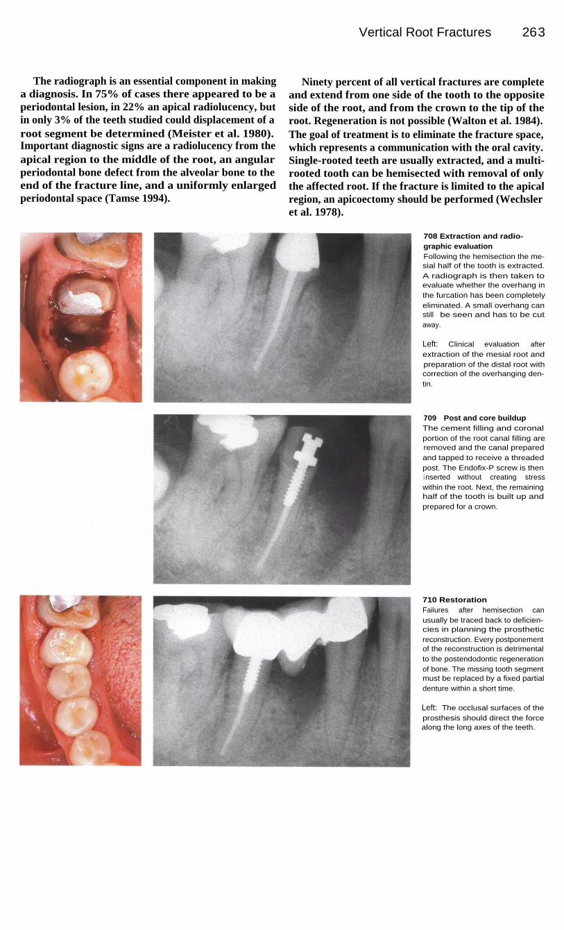
Vertical Root Fractures
263
The radiograph is an essential component in makinga diagnosis. In 75% of cases there appeared to be aperiodontal lesion, in 22% an apical radiolucency, butin only 3% of the teeth studied could displacement of aroot segment be determined (Meister et al. 1980).Important diagnostic signs are a radiolucency from theapical region to the middle of the root, an angularperiodontal bone defect from the alveolar bone to theend of the fracture line, and a uniformly enlargedperiodontal space (Tamse 1994).
Ninety percent of all vertical fractures are completeand extend from one side of the tooth to the oppositeside of the root, and from the crown to the tip of theroot. Regeneration is not possible (Walton et al. 1984).The goal of treatment is to eliminate the fracture space,which represents a communication with the oral cavity.Single-rooted teeth are usually extracted, and a multi-rooted tooth can be hemisected with removal of onlythe affected root. If the fracture is limited to the apicalregion, an apicoectomy should be performed (Wechsleret al. 1978).
708 Extraction and radio-graphic evaluationFollowing the hemisection the me-sial half of the tooth is extracted.A radiograph is then taken toevaluate whether the overhang inthe furcation has been completelyeliminated. A small overhang canstill be seen and has to be cutaway.
Left: Clinical evaluation afterextraction of the mesial root andpreparation of the distal root withcorrection of the overhanging den-tin.
709
Post and core buildupThe cement filling and coronalportion of the root canal filling areremoved and the canal preparedand tapped to receive a threadedpost. The Endofix-P screw is theni nserted without creating stresswithin the root. Next, the remaininghalf of the tooth is built up andprepared for a crown.
710 RestorationFailures after hemisection canusually be traced back to deficien-cies in planning the prostheticreconstruction. Every postponementof the reconstruction is detrimentalto the postendodontic regenerationof bone. The missing tooth segmentmust be replaced by a fixed partialdenture within a short time.
Left: The occlusal surfaces of theprosthesis should direct the forcealong the long axes of the teeth.
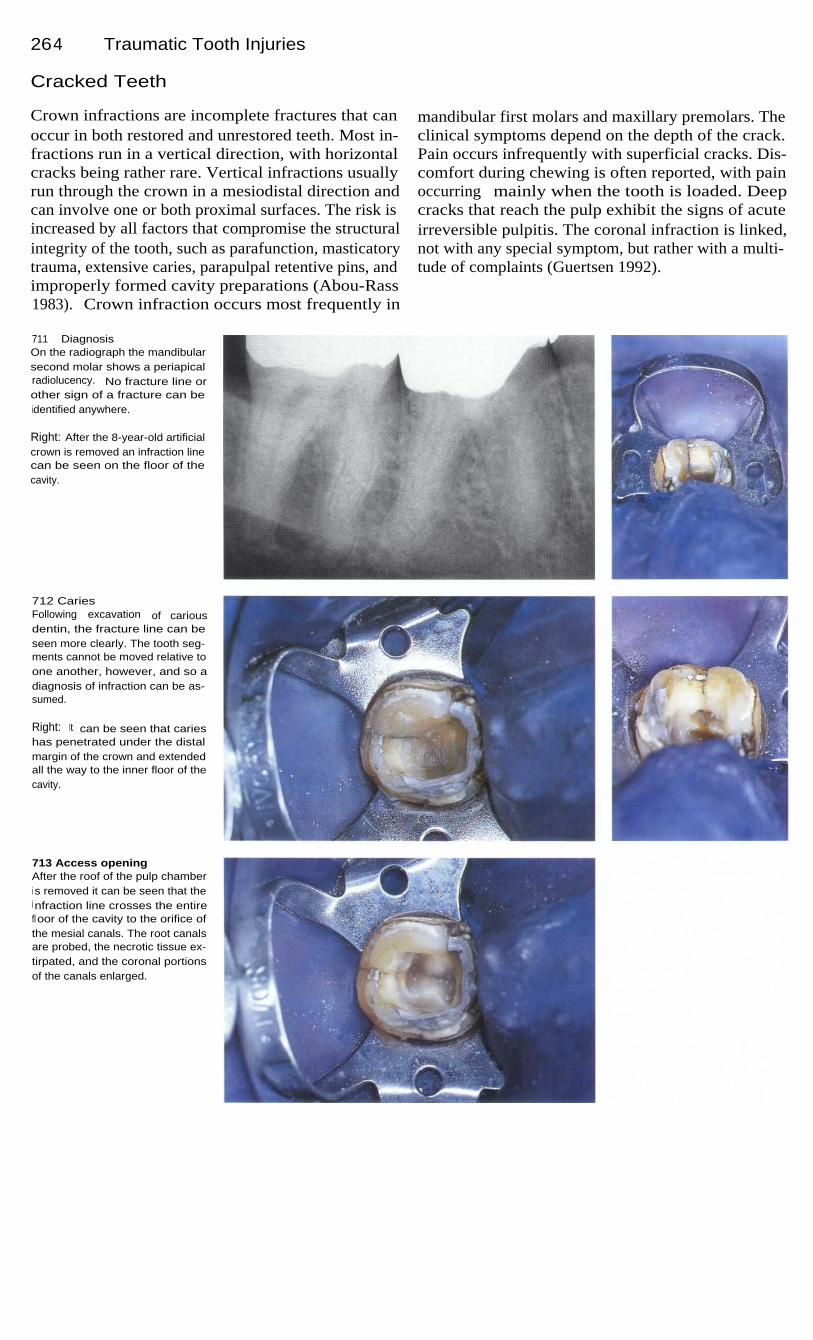
264
Traumatic Tooth Injuries
Cracked Teeth
Crown infractions are incomplete fractures that canoccur in both restored and unrestored teeth. Most in-fractions run in a vertical direction, with horizontalcracks being rather rare. Vertical infractions usuallyrun through the crown in a mesiodistal direction andcan involve one or both proximal surfaces. The risk isincreased by all factors that compromise the structuralintegrity of the tooth, such as parafunction, masticatorytrauma, extensive caries, parapulpal retentive pins, andimproperly formed cavity preparations (Abou-Rass1983). Crown infraction occurs most frequently in
mandibular first molars and maxillary premolars. Theclinical symptoms depend on the depth of the crack.Pain occurs infrequently with superficial cracks. Dis-comfort during chewing is often reported, with painoccurring mainly when the tooth is loaded. Deepcracks that reach the pulp exhibit the signs of acuteirreversible pulpitis. The coronal infraction is linked,not with any special symptom, but rather with a multi-tude of complaints (Guertsen 1992).
711 DiagnosisOn the radiograph the mandibularsecond molar shows a periapicalradiolucency. No fracture line orother sign of a fracture can beidentified anywhere.
Right: After the 8-year-old artificialcrown is removed an infraction linecan be seen on the floor of thecavity.
712 CariesFollowing excavation of cariousdentin, the fracture line can beseen more clearly. The tooth seg-ments cannot be moved relative toone another, however, and so adiagnosis of infraction can be as-sumed.
Right: It can be seen that carieshas penetrated under the distalmargin of the crown and extendedall the way to the inner floor of thecavity.
713 Access openingAfter the roof of the pulp chamberi s removed it can be seen that thei nfraction line crosses the entirefloor of the cavity to the orifice ofthe mesial canals. The root canalsare probed, the necrotic tissue ex-tirpated, and the coronal portionsof the canals enlarged.

Cracked Teeth
265
Next, a careful inspection of the affected region ismade with loupes, ultraviolet light, and the electroniccaries meter. If there is still doubt, the occlusal regionis stained with methylene blue. These techniques donot reveal the exact length, depth, or direction of thecrack. After other potential causes have been excludedthe patient should be asked to rapidly close the teethseveral times. Pain upon loading is evidence of anincomplete vertical fracture. The first therapeutic pro-cedure is the stabilization of the crown with a steelband (Liu and Sidhu 1995).
If symptoms of pulpitis are present the tooth isopened and endodontically treated. The root canalsshould not be enlarged excessively. If the tooth isasymptomatic after placement of an interim dressing,the canals are filled with thermoplastic gutta-percha.However, complications did not occur following rootcanal treatment of teeth in one study, irrespective ofthe technique used (Liu and Sidhu 1995). The coronalportion of the tooth is then sealed with an adhesivecement and composite material. The final restorationshould be an onlay or a crown (Friedman et al. 1993).
714 Working-length radio-graphAfter careful coronal enlargementof the canals, the first radiographi s taken to determine the workingl ength. The distal length is thencorrected.
Left: Different-sized measurementfiles were inserted into the rootcanals-size 15 in the mesial andsize 20 in the distal.
715 Working-lengthradiographAfter conservative instrumentationof the root canals to size 30 andwith no sign of heavy bleeding, asecond check of the length ismade with a radiograph. A slightreduction in the curvature of themesial root canals can be seen.The working length in the distalcanal is shortened once more.
Left: After irrigating and drying theroot canals, they are firmly packedwith calcium hydroxide.
716 ReinstrumentationAfter 3 months there are no clinicalsymptoms, and pain upon percus-sion is greatly reduced; thus thei nterim dressing is flushed out.Under the operating microscope at20x magnification the course of thei nfraction line can be followed intothe canal entrances.

266 Traumatic Tooth Injuries
717 InstrumentationLeft: The mesial root canals areonce more carefully instrumentedto the size of the AMF and irrigatedwith sodium hypochlorite.
Right: The surgical microscope isused to determine if any calciumhydroxide has remained in thedepths of the root canals.
718 Microscopic evaluationLeft: The distal course of the frac-ture is inspected under 25x magni-fication and all remnants of cariesare excavated.
Right: After the final irrigation thecanals are thoroughly dried and apaper point is used to test for thepresence of lateral bleeding, whichwould indicate a complete fracture.No lateral bleeding is found.
719
Root canal fillingLeft: After the size 30 gutta-perchamaster point is tried and adjustedto fit, the root canal filling is com-pleted with additional gutta-perchapoints, taking care not to exert ex-cessive lateral force.
Right: Next, the gutta-percha pro-truding from the canals is removedwith a hot excavator.
720 Evaluation and follow-upLeft: The gutta-percha should beremoved to a level at least 1 mmbelow the canal orifices. Anybleeding through the infractiongap would complicate the treat-ment, but no bleeding is seenthrough the microscope.
Right: The radiograph shows adense, homogeneous root canalfilling. Three months after the firstappointment the periapical radio-l ucency is seen to have greatlydiminished in size.

267
Postendodontic Restoration
The coronal restoration is an intergral component of the endodontic treatment. Obturated rootcanals can become recontaminated with microorganisms if the coronal restoration is delayed toolong, the temporary filling leaks between appointments, the restoration or tooth structure frac-tures, or the post space preparation extends too near the apex (Saunders and Saunders 1994).Klein et al. (1996) evaluated 742 root canal fillings and found the lowest success rate (46%) withboth a defective coronal restoration and an inadequate root canal filling. A defective restorationin combination with a good root canal filling led to success in 71 % of the cases. Treatment wasrated as successful in 79% of the cases with a good coronal restoration but a defective root canaltreatment, and in 86% of cases with a good seal of both the coronal and apical regions. Thisinvestigation showed that the quality of the coronal seal had as great an influence on success asdid the quality of the root canal treatment.
The choice of the coronal restoration also had a decisive effect on the overall success. In a 2-yearstudy by Safavi et al. (1987) the highest success rate at over 70% was found among end-odontically treated teeth that were restored with crowns. By comparison, temporary restorationsof IRM cement and amalgam fillings were significantly inferior with success rates of 57% and51% respectively. If no coronal seal was placed after endodontic instrumentation, bacteria wereable to penetrate through the unfilled root canal within 48 hours. Well-condensed root canalfillings over which the access preparation was left open were thoroughly contaminated withbacteria after 4-48 days. On the other hand, no bacterial penetration could be found in any of thecanals under tightly sealed access cavities (Torabinejad et al. 1990, Khayat et al. 1993). Bacterialendotoxins can also penetrate through exposed root canal fillings within 3 weeks, but no endo-toxins were found in canals of teeth that had tight coronal seals (Trope et al. 1995 a).
The temporary filling should be at least 3 mm thick in order to resist degradation and penetrationof bacterially contaminated saliva. Thinner fillings make it possible for bacteria to colonize thecanal. Within 3 days up to 85% of teeth that had inadequate temporary fillings becamecontaminated with saliva and bacteria. If a tooth is left open to the oral environment for more than3 days, the entire root canal must be reinstrumented and irrigated and a calcium hydroxide interimdressing placed before the final root canal filling. If a coronal filling or crown has been damagedand the canal has been exposed to salivary contamination for more than 3 months, the entire rootcanal filling must be removed and the canal completely reinstrumented (Magura et al. 1991).

26 8
Postendodontic Restoration
Provisonal Coronal Seal
The provisional restoration should tightly seal theaccess opening between appointments to preventbacterial penetration into the root canal system. Two ofthe most frequently used sealing materials are Cavitand IRM cement. In an investigation of the effective-ness of filling materials by Kazemi et al. (1994), Cavitpermitted partial penetration of a dye to a depth of4.3 mm through the filling material and 4.4 mm alongthe marginal interface.
IRM was penetrated to a depth of only 0.5 mm at thesurface, but 4.9 mm at the margins.
The depth of penetration allowed by these temporaryfilling materials counters the suggestion by Saundersand Saunders (1994) that a thickness of 3.5 mm isadequate. It would be much better to aim for a thicknessof 4 mm or more (Hansen and Montgomery 1993). Thepenetration of saliva into endodontically treated teethafter 3 months was equally severe, regardless ofwhether the access cavity was closed with a 3-mm-thickIRM filling or left open. These fillings should be re-placed within 1 month because thereafter the extent ofleakage more than doubled (Magura et al. 1991).
721
Access openingDue to pain in this mandibularsecond molar, the patient's firstdentist had instrumented the canalsand placed gutta-percha and N-2paste in them as an interim dress-ing. The canals were then reopenedsince the pain persisted.
Right: The first radiograph, takenprior to the initial treatment, showsa periapical radiolucency on thedistal root.
722 InstrumentationDue to leakage and partial loss ofthe provisional filling, bacteria haspenetrated the cavity and, pre-sumably, the canals. The canalsare completely reinstrumented andi rrigated with sodium hypochloritesolution.
Right: The working depth is deter-mined with a radiograph.
723 Interim dressingAfter instrumentation is completed,the root canals are subjected to afinal irrigation and dried. There isno evidence of foul odor or secre-tions. The interim dressing is theni nserted with a rotating spiral pastefiller.
Right: The aqueous mix of calciumhydroxide is packed firmly into thecanals to provide solid contactwith the dentinal walls.

Provisonal Coronal Seal
269
The type of provisional filling material can have anadverse influence on the seal of the definitive restora-tion. IRM cement, Cavit, and Dycal-but not Grossmancement reduced the adhesion of a composite materialto dentin to one-half that of the control specimens(Macchi et al. 1992). The type of interim dressingwithin the root canal had no significant effect on theability of the restorative material to seal the cavity,however. Neither eugenol, formocresol, nor chloro-phenol resulted in greater penetration around the finalfilling (Rutledge and Montgomery 1990). Placing a
cotton pellet over the canal entrance before insertion ofthe provisional filling is not recommended because itincreases the possibility of penetration. Cotton pelletswere placed on cavity floors directly under 5-mm-thickprovisional fillings; when IRM was used, the pelletswere discolored twice as often as when Cavit was used(Kazemi et al. 1994).
If the orifices of the canals are sealed with thetemporary filling material, it is very unlikely that theinterim dressing will be softened by saliva that mightpenetrate under the leaky margins of a crown or filling.
724 Provisional coronal fillingThree months after the initial treat-ment the integrity of the 4-mm-thick provisional zinc phosphatecement filling is evaluated undera rubber dam. Only a minimalamount of cement loss is detected.
Left: The interim filling placedafter the first sitting covers the en-trances to the canals and seals theaccess cavity from the oral environ-ment.
725 Checking the integrity ofthe interim dressingThe pulp chamber is reopened, allthe cement filling removed, and
the calcium hydroxide interimdressing checked. No breakdownis evident, thus contamination withsaliva can be ruled out.
Left: The master point radiographi s used to evaluate both the posi-tion of the gutta-percha point andthe reduction in size of the peri-apical radiolucency.
726
Evaluation of the final rootcanal fillingThe three canals are filled withgutta-percha and AH-Plus by thel ateral condensation technique.Then the gutta-percha is cut offbelow the canal orifices and thecavity sealed with zinc phosphatecement and an adhesive filling.
Left: The radiograph shows ahomogeneous root canal fillingwith a dense apical seal.

270
Postendodontic Restoration
Fracture Risk and Partial Veneer Crowns
Fractures of endodontically treated teeth are frequentlyattributed to reduced physical properties of the dentin.There is, however, no difference between the strengthof the dentin of endodontically treated teeth and that ofvital teeth. The type of access cavity and final restora-tion do influence the risk of fracture, however. Cuttinga small preparation reduces the load a tooth can with-stand to 81 % that of an intact tooth; a more extendedpreparation reduces it to 61 %. An endodontic accesspreparation further reduces the strength of the crownby half (Panitvisai and Messer 1995).
The dentin of endodontically treated teeth is no lessresistant to fracture than that of vital teeth. Neitherdehydration nor the age of the patient has a significanteffect on the elasticity of dentin (Huang et al. 1992). Itis the removal of the roof of the pulp chamber and themarginal ridges that substantially reduces the strengthof the tooth. Intact molars fractured under a load of241 kg, and an extended preparation reduced the maxi-mum load to 222 kg. Teeth that also had an endodonticaccess cavity fractured under a load of only 121 kg(Howe and McKendry 1990).
727 Access preparationThe mandibular first molar with athree-quarter crown is associatedwith clinical symptoms of pain andtenderness to percussion and alsohas a small radiolucency aroundthe tip of the distal root.
Right: After preparing a generousaccess cavity, the integrity of thecrown is evaluated. The coronalportion of each canal is subse-quently prepared with rotary drills.
728 NecrosisThe roof of the pulp chamber is re-moved and the entrances to theroot canals located. With the oper-ating microscope necrotic tissuecan be seen in all three canals.
Right: The canals are irrigated andi nstrumented with the help of RC-Prep.
729 InstrumentationAfter establishing the workingl enght on a radiograph, the threecanals are instrumented and theapical portions prepared to size30. The canals are enlarged coro-nally with Gates-Glidden drills.

Fracture Risk and Partial Veneer Crowns
271
The altered mechanical properties of the preparedtooth increase its susceptibility to fracture. The restora-tion of endodontically treated teeth with amalgam hasproduced rather disappointing results over an observa-tion period of 20 years. Teeth with MOD fillings frac-tured much more frequently than mesio-occlusodistal(MOD) teeth with intact marginal ridges. Only30-40% of premolars restored in this way were stillintact at the end of the observation period. Teeth withsmaller restorations had a much higher survival rate at80% (Hansen et al. 1990).
MOD amalgam restorations reduced the danger offracture and increased the strength of prepared teeth by61-82%; the load that could be withstood was increasedby 125% by binding the cusps together by means of castpartial veneer crowns. An amalgam restoration thatcovered the cusps increased the strength of the mesialcusp by 175%, and the distal cusp by 102%. End-odontically treated posterior teeth therefore should berestored with at least a metal casting that encompassesthe cusps to ensure protection against tooth fracture(Linn and Messer 1994).
730 Master pointAn interim dressing is left in placefor 4 weeks. At the second ap-pointment the root canals are irri-gated and dried and three gutta-percha master points are fitted andmeasured on a radiograph. At thesame time, the depth of the instru-mentation is verified.
731
Root canal obturationThe canals are completely filledwith gutta-percha points and aresin sealer. The results are thenchecked with a radiograph. Theroot canal treatment is successful,with freedom from clinical symp-toms and healing of the periapicall esion.
732 RestorationImmediately after the root canalfilling is placed the crown is builtup with glass ionomer cement. Thetooth is prepared for a new partialveneer crown, an impression ismade, and a provisional crownplaced. One week later the finalrestoration is cemented.
Left: The partial veneer crown,which protects the tooth from over-loading and recontamination, isevaluated for marginal adaptation.
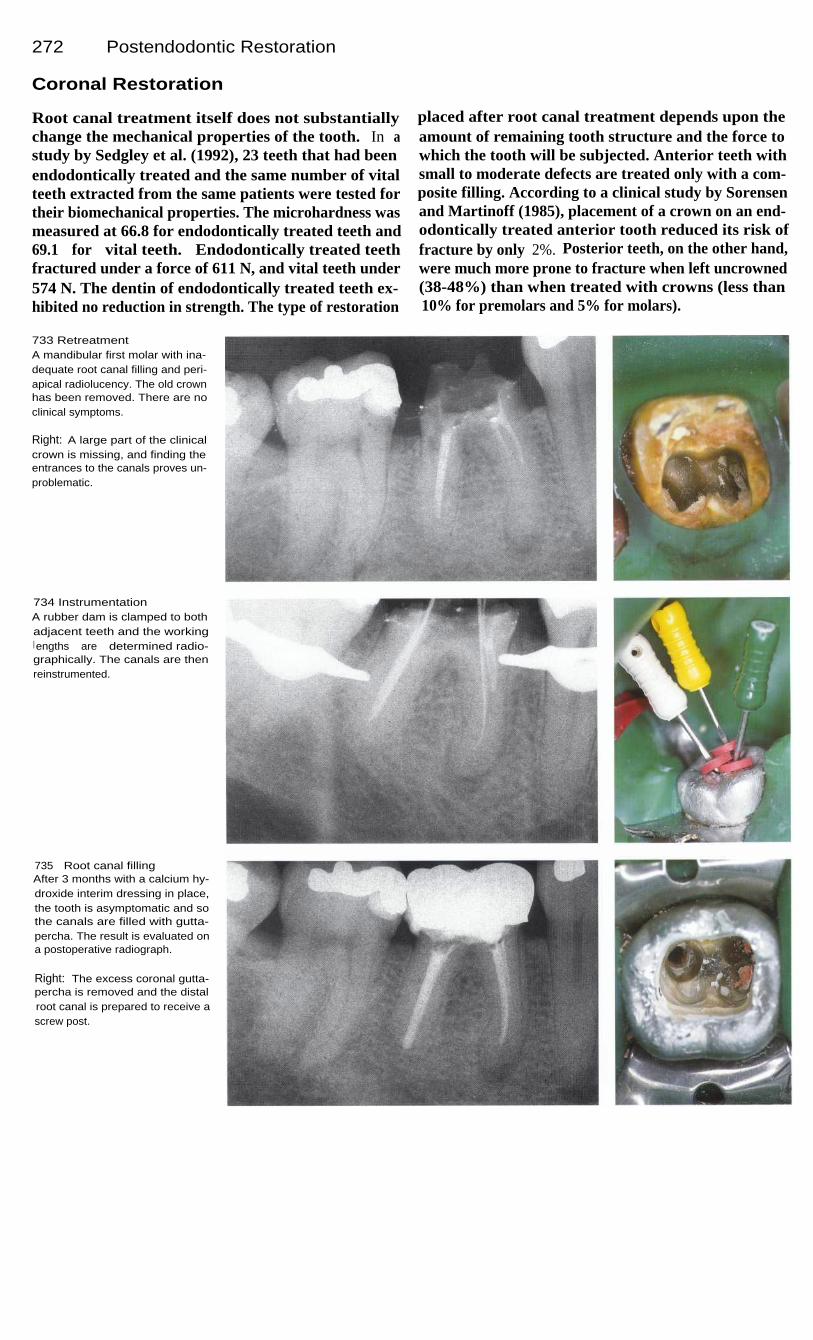
272
Postendodontic Restoration
Coronal Restoration
Root canal treatment itself does not substantiallychange the mechanical properties of the tooth. In astudy by Sedgley et al. (1992), 23 teeth that had beenendodontically treated and the same number of vitalteeth extracted from the same patients were tested fortheir biomechanical properties. The microhardness wasmeasured at 66.8 for endodontically treated teeth and69.1 for vital teeth. Endodontically treated teethfractured under a force of 611 N, and vital teeth under574 N. The dentin of endodontically treated teeth ex-hibited no reduction in strength. The type of restoration
placed after root canal treatment depends upon theamount of remaining tooth structure and the force towhich the tooth will be subjected. Anterior teeth withsmall to moderate defects are treated only with a com-posite filling. According to a clinical study by Sorensenand Martinoff (1985), placement of a crown on an end-odontically treated anterior tooth reduced its risk offracture by only 2%. Posterior teeth, on the other hand,were much more prone to fracture when left uncrowned(38-48%) than when treated with crowns (less than10% for premolars and 5% for molars).
733 RetreatmentA mandibular first molar with ina-dequate root canal filling and peri-apical radiolucency. The old crownhas been removed. There are noclinical symptoms.
Right: A large part of the clinicalcrown is missing, and finding theentrances to the canals proves un-problematic.
734 InstrumentationA rubber dam is clamped to bothadjacent teeth and the workingl engths are determined radio-graphically. The canals are thenreinstrumented.
735
Root canal fillingAfter 3 months with a calcium hy-droxide interim dressing in place,the tooth is asymptomatic and sothe canals are filled with gutta-percha. The result is evaluated ona postoperative radiograph.
Right: The excess coronal gutta-percha is removed and the distalroot canal is prepared to receive ascrew post.

Coronal Restoration
273
The loss of tooth structure can have an adverseeffect on the mechanical properties of a tooth. Thus itis the quantity of dentin remaining in the crown thatlargely determines the strength of an endodonticallaytreated tooth. If the tooth is prepared for an artificialcrown, its fracture resistance under an oblique load isreduced to 46 kg, compared with 54 kg for teeth thathave not been prepared. If the prepared dentin is pre-treated with EDTA and built up with composite, thetooth's resistance is once more comparable with that ofan untreated tooth (Sornkul and Stannard 1992).
Before a crown is made, an adhesively bonded coremust be place. Then a veneered cast crown can beplaced over it. Success is also influenced by the choiceof cementing agent. Under in vivo dye penetrationtests, crowns cemented with composite cement showedthe least leakage at 16%, followed by a glass ionomercement at 33.2%. More than half of the crowns ce-mented with polycarboxylate or zinc phosphate cementshowed marginal leakage (White et al. 1995).
736 Post-retained coreThreads are cut into the walls ofthe post space and the post isgently screwed into place. The re-maining tooth structure is etched,treated with a dentin bondingagent, and built up with composite.
Left: The screw post is coated withpolycarboxylate cement and slowlyscrewed into the distal canal.
737 Artificial crownAfter 1 more week the definitivecrown is cemented with glass ion-omer cement. This 1-year follow-up radiograph shows optimummarginal adaptation. The adjacentfilling has also been replaced.
Left: Screw posts for treating pos-terior teeth (Straumann).
738 Follow-upThe readiograph taken 3 yearsafter treatment shows almost totalregeneration of the periapical boneat the apex of the mesial root.
Left: The tooth can withstandnormal loading. Before the metal-ceramic crown is placed, the crownis lengthened surgically to providegreater retention.

274
Postendodontic Restoration
Endodontic Posts
A post-and-core anchored in the root canal was oncethought to actually strengthen the weakened root.However, laboratory studies have shown that the prep-aration of a post space further weakens the tooth struc-ture, and the placement of the post does not leave thetooth any stronger than it was before the preparationwas made. Posts anchored in the root canals have nostrengthening effect on the roots and serve only toprovide additonal retention for the core and artificialcrown (deCleen 1992).
The gutta-percha can be softened by placing a dropof organic solvent such as eucalyptol on the coronalend of the root canal filling. It can also be softened witha hot spreader. However, the apical seal is said to bebetter preserved after mechanical removal than afterchemical dissolution (Camp and Todd 1983). Basically,it makes no difference whether the post space is prep-ared as soon as the root canals are filled or whether thisis delayed to a later appointment. Portell et al. (1982)view the immediate removal of excess gutta-percha asadvantageous.
739 InstrumentationRadiographic length determinationfollowing preparation of the accesscavity on a mandibular first molar.
Right: Patency of the root canals istested with a size 15 Hedstrom file.Then the canal is enlarged by cir-cumferential filing.
740
Enlargement of thecoronal portionLeft: The straight portion of theroot canal is enlarged with Gates-Glidden drills of different sizesfollowing a modified step-downtechnique.
Right: The length and size of theGates-Glidden drill used is record-ed so that later the size of thepoint can be selected to match thecoronal enlargement.
741
Preparation of the deepportionI n spite of the initial length mea-surement, the canals were over-i nstrumented. The working lengthis checked again with the AMFsand found to require a reduction of1 mm in the distal root and 0.5 mmi n the mesial root.
Right: The two mesial root canalsare enlarged to size 30 and thedistal canal to size 35. They areshaped by using the balancedforce technique.
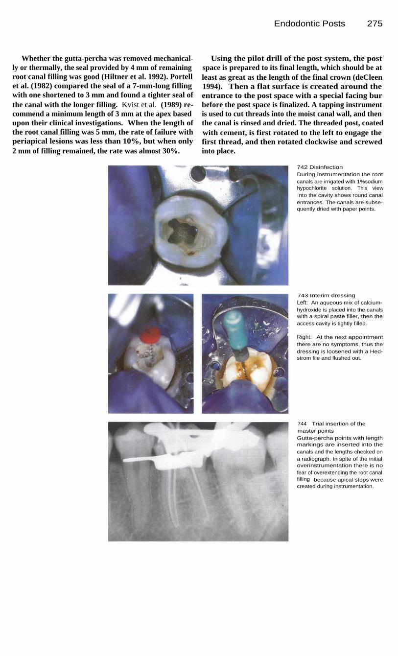
Endodontic Posts
275
Whether the gutta-percha was removed mechanical-ly or thermally, the seal provided by 4 mm of remainingroot canal filling was good (Hiltner et al. 1992). Portellet al. (1982) compared the seal of a 7-mm-long fillingwith one shortened to 3 mm and found a tighter seal ofthe canal with the longer filling. Kvist et al. (1989) re-commend a minimum length of 3 mm at the apex basedupon their clinical investigations. When the length ofthe root canal filling was 5 mm, the rate of failure withperiapical lesions was less than 10%, but when only2 mm of filling remained, the rate was almost 30%.
Using the pilot drill of the post system, the postspace is prepared to its final length, which should be atleast as great as the length of the final crown (deCleen1994). Then a flat surface is created around theentrance to the post space with a special facing burbefore the post space is finalized. A tapping instrumentis used to cut threads into the moist canal wall, and thenthe canal is rinsed and dried. The threaded post, coatedwith cement, is first rotated to the left to engage thefirst thread, and then rotated clockwise and screwedinto place.
742 DisinfectionDuring instrumentation the rootcanals are irrigated with 1%sodiumhypochlorite solution. This viewi nto the cavity shows round canalentrances. The canals are subse-quently dried with paper points.
743 Interim dressingLeft: An aqueous mix of calcium-hydroxide is placed into the canalswith a spiral paste filler, then theaccess cavity is tightly filled.
Right: At the next appointmentthere are no symptoms, thus thedressing is loosened with a Hed-strom file and flushed out.
744
Trial insertion of themaster pointsGutta-percha points with lengthmarkings are inserted into thecanals and the lengths checked ona radiograph. In spite of the initialoverinstrumentation there is nofear of overextending the root canalfilling because apical stops werecreated during instrumentation.

276
Postendodontic Restoration
745 Tooth fractureEven though the tooth was filledwith a glass ionomer cement afterthe initial treatment, the lingualwall of the crown has fracturedaway. This complication makes itnecessary to insert a post to in-crease the retention of the corebuildup.
746 Radiographic evaluationThis radiograph, taken immediatelyafter the root canals were filled withgutta-percha, shows dense, homo-geneous obturation of the apicesand verifies that there is no over-extension of the filling material.
Right: Next, part of the gutta-percha is removed with a Gates-Glidden drill.
747 PreparationLeft: A coronal portion of the gutta-percha is removed to a depth of4-5 mm with size 1 and size 2Gates-Glidden drills.
Center: The pilot drill specified inthe Radix Anchor system is usedto make a preliminary channel tothe desired depth.
Right: A flat seat is preparedaround the entrance to each postspace with the special diamond-coated instrument.
748 Monitoring radiographA radiograph is taken during prep-aration of the post spaces. This isrecommended to help avoid per-forations. It is evident that thei nstrument deviates slightly fromthe center of the canal, but this canstill be easily corrected.

Endodontic Posts 277
749 PreparationLeft: After the pilot hole is drilled, aspecial drill with a diameter corre-sponding exactly to the size of theRadix Anchor is used to finish pre-paring the post space.
Right: Next, the entrance to thechannel is flattened once more tominimize splitting forces.
750 Radix AnchorAfter the Radix Anchor is cemented,a radiograph is taken to check thedepth of the post and the length ofremaining root canal filling.
Left: A measuring gauge is usedto check the depth reached by thedrill before the internal threads arecut.
751
I nsertion of the postLeft: The post space is finishedwith a standardized drill.
Center: After cutting i nternalthreads, the Radix Anchor is coat-ed with cement and gently screw-ed into place.
Right: A composite core is built upover the fins radiating from thecoronal portion of the post.
752 Core buildupAfter both Radix Anchors havebeen cemented, the cavity is etchedand treated with a dentin bondingagent, and then a light-curingcomposite is applied. Thereafter,the tooth is prepared for a castcrown, and an impression is made.

278
Postendodontic Restoration
Cast Post-Cores
In order to test specific post-and-core systems, Plas-mans et all. (1988) inserted 7-mm-long post-cores intothe distal canals of extracted teeth and found thehighest fracture resistance (4460 N) with a cast post-core system. Every test ended with fracture of theentire tooth and so it was not possible to make morethan one restoration on the same tooth. Prefabricatedposts with composite cores withstood 2750 N but wereinsignificantly stronger than an adhesive compositebuildup extending 3 mm into the canal with no post.Here, however, only one fracture occurred within the
composite material.As with all systems, a cast post-core must have ade-
quate length. Increasing the length of the post from5 mm to 8 mm increased its retention by 47%. Guidelines for the length of the post space are: first, it shouldmeasure two-thirds of the total canal length; second, itshould be as long as the future crown length; and third,it should equal half of the bone-supported root length.Marginally, at least 2 mm of root dentin shouldsurround the cast post. This will double the resistanceto fracture (Wagnild and Mueller 1994).
753 Presenting conditionLeft: The lingual wall of the lowermolar has fractured off, leaving ani nadequate amalgam filling. Thereare no clinical symptoms. To savethis posterior-most tooth in thearch it would be necessary toperform endodontic treatment andplace a core and crown.
Right: The radiograph taken beforethe beginning of treatment showsnothing unusual in the periapicalregion.
754
Root canal treatmentLeft: The three root canals are in-strumented and a calcium hydroxi-de interim dressing is placed. Atthe second appointment gutta-percha points are condensed intothe canals and cut off at the levelof the canal orifices.
Right: Homogeneous root canalfillings can be seen on the post-operative radiograph.
755 Post-core preparationLeft: To create space for the post,some of the gutta-percha is re-moved from the distal canal andthe canal is widened with a Peesoreamer to half of the workinglength.
Right: The remaining coronal toothstructure is shaped to create resis-tance form and to permit a castingto embrace the tooth at the mar-gins. An impression is then madeof the arch, and a stone cast ismade in the laboratory.
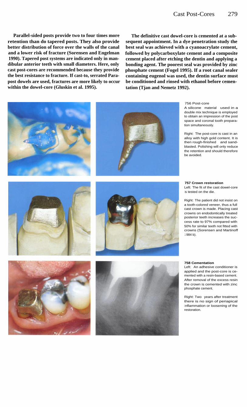
Cast Post-Cores
279
Parallel-sided posts provide two to four times moreretention than do tapered posts. They also providebetter distribution of force over the walls of the canaland a lower risk of fracture (Sorensen and Engelman1990). Tapered post systems are indicated only in man-dibular anterior teeth with small diameters. Here, onlycast post-cores are recommended because they providethe best resistance to fracture. If cast-to, serrated Para-post dowels are used, fractures are more likely to occurwithin the dowel-core (Gluskin et al. 1995).
The definitive cast dowel-core is cemented at a sub-sequent appointment. In a dye penetration study thebest seal was achieved with a cyanoacrylate cement,followed by polycarboxylate cement and a compositecement placed after etching the dentin and applying abonding agent. The poorest seal was provided by zincphosphate cement (Fogel 1995). If a root canal sealercontaining eugenol was used, the dentin surface mustbe conditioned and rinsed with ethanol before cemen-tation (Tjan and Nemetz 1992).
756 Post-coreA silicone material used in adouble mix technique is employedto obtain an impression of the postspace and coronal tooth prepara-tion simultaneously.
Right: The post-core is cast in analloy with high gold content. It isthen rough-finished and sand-blasted. Polishing will only reducethe retention and should thereforebe avoided.
757 Crown restorationLeft: The fit of the cast dowel-coreis tested on the die.
Right: The patient did not insist ona tooth-colored veneer, thus a fullcast crown is made. Placing castcrowns on endodontically treatedposterior teeth increases the suc-cess rate to 97% compared with50% for similar teeth not fitted withcrowns (Sorensen and Martinoff1 984 b).
758 CementationLeft: An adhesive conditioner isapplied and the post-core is ce-mented with a resin-based cement.After removal of the excess resinthe crown is cemented with zincphosphate cement.
Right: Two years after treatmentthere is no sign of periapicali nflammation or loosening of therestoration.
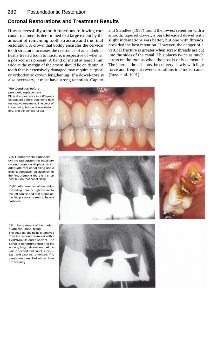
280
Postendodontic Restoration
Coronal Restorations and Treatment Results
How successfully a tooth functions following rootcanal treatment is determined to a large extent by theamount of remaining tooth structure and the finalrestoration. A crown that bodily encircles the cervicaltooth structure increases the resistance of an endodon-tically treated tooth to fracture, irrespective of whethera post-core is present. A band of metal at least 1 mmwide at the margin of the crown should lie on dentin. Atooth that is extensively damaged may require surgicalor orthodontic crown lengthening. If a dowel-core isalso necessary, it must have strong retention. Caputo
and Standlee (1987) found the lowest retention with asmooth, tapered dowel; a parallel-sided dowel withslight indentations was better, but one with threadsprovided the best retention. However, the danger of avertical fracture is greater when screw threads are cutinto the sides of the canal. This places twice as muchstress on the root as when the post is only cemented.The internal threads must be cut very slowly with lightforce and frequent reverse rotations in a moist canal(Ross et al. 1991).
759 Condition beforeprosthetic replacementClinical appearance in a 63-year-old patient before beginning newrestorative treatment. The color ofthe existing bridge is unsatisfac-tory, and the pontics jut out.
760 Radiographic diagnosisOn the radiograph the maxillarysecond premolar displays an in-adequate root canal filling and adistinct periapical radiolucency. Inthe first premolar there is a shortpost but no root canal filling!
Right: After removal of the bridgeextending from the right canine tothe left canine and first premolar,the first premolar is seen to have apost-core.
761
Retreatment of the inade-quate root canal fillingThe gutta-percha point is removedfrom the second premolar with aHedstrom file and a solvent. Thecanal is reinstrumented and theworking length determined. At thistime a second root canal is identi-fied and also instrumented. Thecanals are then filled with an inte-rim dressing.

Coronal Restorations and Treatment Results 281
The most important factor in preventing a fracture isnot the design of the post but the final crown. Themajority of studies on fractures of roots treated withposts were carried out with no coronal restorations inplace. However, the differences between the individualpost systems disappear when a crown is cemented(Gelfand et al. 1984). Sorensen and Martinoff (1984 a)showed in a clinical study that the frequency of fractu-res depends much less on the post than on the type ofcoronal restoration.
Weine et al. (1991) followed 138 teeth treated withparallel-sided posts and crowns and reported a failurerate of only 6.5% after 10 years. The quality of thecoronal restoration plays an important role in the suc-cess of the overall treatment. In an evaluation of 1010radiographs, teeth with good coronal restorations weresuccessful in 80% of the cases, while a good root canalfilling was associated with success in 75.7%. A poorcoronal restoration, however, was associated with aperiapical lesion in 48.6% of the cases and an inade-quate root canal filling in 30.2% (Ray and Trope 1995).
762
Root canal obturationThe radiograph shows a homo-geneous and well-adapted rootcanal filling. Because of the ec-centric projection angle, the sepa-rate canals can easily be seen.
Left: On the radiograph taken withan orthoradial projection thereappears to be only one root canal.The reason for this is the super-imposition of the two canals.
763
Bridge fittingWith the old bridge, the upper lipwould occasionally hang on thecervical edge of the pontics. Thenewly constructed fixed partialdenture exhibits a good arch form;the upper lip appears full againand glides over the cervical mar-gins of the pontics without inter-ference.
Left: A follow-up radiograph 2years after treatment shows regen-eration of the periapical bone andthe success of the treatment.
764 Completed restorationThe alveolar ridge is augmentedlabially with a subepithelial con-nective-tissue transplant. At thepatient's request, the amalgamtattoo is left in place. The ponticsare intentionally recessed slightlyinto the soft tissue.
Left: The teeth are bound togetherwith a custom-milled precisionattachment.
Prosthodontic treatmentby G. Mayerhofer

282
Postendodontic Restoration
Restoration of Hemisected Teeth
Through hemisection an unnecessary sacrifice of toothstructure can be avoided and the length and integrityof the dental arch maintained. Intact adjacent teethneed not then be included in the reconstruction. A pre-fabricated, standardized post is cemented into the rootcanal if there is still adequate coronal tooth structureremaining. With extensive loss of tooth structure, acast post-core is indicated. These post buildups do notserve to reinforce the root, but only to replace losttooth structure.
The prosthodontic reconstruction normally takesplace after wound healing, and is delayed only if theprognosis is doubtful. The crown must encircle theprepared tooth. If little dentin can be encompassed theferrule effect is reduced, causing less resistance to frac-ture (Milot and Stein 1992). Failures after hemisectioncan usually be traced back to deficiencies in therestoration. Langer et al. (1981) reported a failure rateof 38% that was frequently associated with a fractureof the tooth.
765 Root canal treatmentThe distal root of the mandibularfirst molar is endodontically treat-ed before the hemisection. Themesial root canals are obliteratedand their orifices cannot be found.
Right: The tooth has been treatedwith an amalgam filling and re-veals a wedge-shaped cervicaldefect that presumably led to ex-posure of the mesiobuccal portionof the pulp.
766 HemisectionThe tooth is separated through thehalf that is to be removed. Themesial root is then luxated andextracted. After the wound hashealed, a prefabricated post is ce-mented into the distal root canal.The core buildup and the firstpremolar are prepared for a fixedpartial denture and an impressionis made.
Right: A radiograph taken after thehemisection and before insertionof the post and core.
767 ReconstructionThe bridge is cemented with zincphosphate cement and the occlu-sion is adjusted. Due to financialconsiderations, the second molar isnot included in the reconstruction.The dentin of the treated root iscompletely encircled by the crownto provide maximum resistance tof ractu re.

283
Bleaching of Teeth
Discolorations of the crowns of endodontically treated teeth and even vital anterior teeth presentan esthetic problem. The cause of tooth discoloration can be a delayed reaction to trauma withrupture of blood vessels, or remnants of necrotic pulp tissue or root canal filling material in thecoronal pulp chamber. Discolorations can also be brought about by filling materials, medications,and external influences. If a root canal filling is not removed to a level at or below the cemento-enamel junction, ingredients of root canal filling pastes and metallic salts from silver points canpenetrate along the coronally curving dentinal tubules to discolor the clinical crown. Inadequateroot canal fillings must be replaced before the beginning of the tooth-bleaching procedure.Bleaching is a noninvasive method of lightening a tooth's color without resorting to prosthodontictreatment (Beer 1995).
Concerning the prognosis of the bleaching procedure,Brown (1965) reported relapse (i. e., renewed darken-ing of the tooth) in 25% of cases observed over aperiod of 5 years. One of the causes was leakagearound fillings that permitted penetration of stains orrecolonization of the cavity by bacteria. The risk ofrelapse also seemed to depend on the extent of theoriginal discoloration and the rapidity with which thediscoloration appeared. Over a period of 8 years Fried-man et al. (1988) found the color stability to be good inmore than half of the bleached teeth they followed, andstill acceptable in 29%.
Relapse does occur after the crowns of endodon-tically treated teeth have been bleached, but nowthe cases requiring subsequent restorative treatmentcan be reduced to half the number originally con-sidered necessary. Pre-eruptive deposits of tetracyclinerespond well for a short time to a combined bleachingprocedure, but the result does not always last. Relapseoften occurs quite soon so that repeated bleaching be-comes necessary after 1 year. Presumably the depositsof stain reoccur in the tooth, or the opaque effectdecreases with remineralization of the enamel surfaceand allows the deeper-lying discoloration to showthrough the enamel once more (Walton et al. 1982).
External root resorption can occur over a long peri-od of time following tooth bleaching. Harrington andNatkin (1979) described seven cases in which teethbleached with hydrogen peroxide activated by a heatsource experienced root resorption 2-7 years later.Lado et al. (1983) postulated that dentin was denaturedby the bleaching. In all the cases reported, however,resorption was preceded by trauma. Covering the rootcanal filling with a layer of cement approximately2 mm thick at a level 1 mm below the cementoenameljunction should impede the penetration of the dentinaltubules by hydrogen peroxide. It is assumed that thebleaching agent diffuses from the cavity throughdefects in the cement within the root, through thedentinal tubules, and into the periodontal tissue whereit can initiate an inflammatory reaction by altering the
In two studies conducted independently of oneanother, it was observed that with the application of amixture of sodium perborate and hydrogen peroxidethe pH value was reduced after 4-11 days to 6.5 in oneinstance, and increased to 8.3 in the other. Whencalcium hydroxide was placed in the cavity after thelast bleaching, the pH was neutral at 7.2 within 4-10days (Fuss et al. 1982, Kehoe 1987).

284
Bleaching of Teeth
Causes of Tooth Discoloration
Bacterial, mechanical, and chemical irritations can leadto necrosis of the pulp. Decomposition products pene-trate the dentinal tubules and stain the surroundingdentin. This discoloration can be removed by internalbleaching. Intrapulpal hemorrhage with lysis of eryth-rocytes can occur following traumatic injury.
Distintegration products such as iron sulfide pene-trate the dentinal tubules in these cases. If the pulptissue does not become necrotic the tooth discolorationwill fade. Remaining discolorations can be lightenedby internal bleaching (Freccia et al. 1982).
Traumatic injuries lead to destruction of bloodvessels and odontoblasts and this can stimulate theformation of large amounts of tertiary dentin, causingobliteration of the root canal. These crowns slowly losetheir translucency and may assume a yellowish-browncolor. In these cases, bleaching must be preceded byroot canal treatment (Jacobsen and Kerkes 1977).
Discolorations can also arise through the incorpora-tion of substances during tooth development. The bestknown of these are tetracycline and fluoride discolora-tions that can be bleached externally (Arens et al. 1972).
768 Crown discolorationThe maxillary central incisor is se-verely discolored and has a defec-tive composite filling. It no longerresponds to a sensitivity test.
Right: The radiograph shows ani nadequate root canal filling that istoo short apically but extends intothe coronal access cavity, ratherthan being cut off beyond thecanal orifice.
769 Stain depositsA section through the enamel sur-face under polarized light showsfracture lines and a broad area ofi ncipient caries. These are contra-i ndications to vital bleaching.
Right: Under the optical micro-scope, remnants of root canal fillingmaterial can be seen in the dentinaltubules. This causes the type of dis-coloration seen in the case shownabove.
770 RetreatmentThe root canal filling is removedunder a rubber dam and the canali s instrumented, irrigated, andfilled with a calcium hydroxidei nterim dressing. Ten days later thecanal is obturated.
Right: Radiograph of the rootcanal filling, removed to a level2 mm beyond the entrance to theroot canal and then covered with acement base.

Causes of Tooth Discoloration
285
In addition to natural causes, tooth discoloration canalso have iatrogenic causes. Root canal filling materialis the most frequent and important cause of tooth dis-coloration. Filling material left in the cavity results in agray-to-black discoloration of the tooth crown. Thiscan be lightened using the internal "walking bleach"method, alone or combined with external bleaching.The prognosis for the bleaching effect depends on thecomposition of the sealer: metal components are diffi-cult to remove and retreatment is often necessary afterthe bleaching procedure (Burgt and Plasschaert 1986).
Remnants of necrotic pulp tissue in the coronalcavity produce little discoloration but are easy toremove and bleach. Medications introduced into thecanal such as phenol or iodoform pastes can producevarious degrees of discoloration after long contact withdentin (Boksman et al. 1983). Poorly sealed compositefillings are penetrated by stains and bacteria. Place-ment of a lingual amalgam filling can result in a graydiscoloration of the crown that is difficult to bleach.
771
Stain depositsThe view into the opened cavityreveals the deposits of stainingmaterial that must be removed bythe bleaching process. The smearl ayer on the dentinal surfaceblocks entrance to the dentinaltubules and must be removed be-fore bleaching is attempted.
772
Etching the cavityA phosphoric acid gel is placed inthe cavity for 10-20 seconds andthen washed out with a water spray
for 30 seconds.
Left: A syringe can be used toapply the etching gel in a con-trolled manner.
773
Dentinal tubulesAfter the dentin in the cavity isetched, the dentinal tubules arewide open and the bleaching agentcan penetrate them unimpeded.However, because of the danger ofcausing external root resorption,the etching agent must be usedwith restraint and its use limited toseverely discolored teeth.

286
Bleaching of Teeth
Thermocatalytic Bleaching
The thermocatalytic method uses hydrogen peroxidesolution placed on gauze strips stretched over the toothsurfaces. This is warmed by means of a special lamp ora thermostatically controlled heating wand with thetemperature never exceeding 55 °C (130 °F). A briefetching of the surface with phosphoric acid is recom-mended before vital bleaching. Professional toothcleaning will remove the pellicle and superficial stains(Spasser 1961, Nutting and Poe 1967). The enamel iscleaned, the gingiva is coated with Vaseline to preventirritation of its surface, and an extra heavy rubber dam
is applied. When the discoloration is severe or the stainis especially stubborn, the entire enamel surface isetched for 10 seconds. Cotton pellets are pulled apartand loosely stretched over the tooth surface. Next, theyare moistened with a few drops of 30% hydrogen per-oxide and warmed with a special heating wand(Touch'n Heat) for 2 minutes. Fresh solution is thenapplied and the bleaching procedure is repeated aboutthree to five times.
774 Bleaching solutionThirty percent hydrogen peroxidesolution is dropped onto the sur-face of the tooth and warmed for2 minutes with a special heatingelement (Touch'n Heat, AnalyticTechnology).
Right: The patient's head is cover-ed with a surgical drape. Thebleaching agent must be changedseveral times and the bleachingprocedure can be repeated threeto five times. Then, all traces ofbleach must be thoroughly rinsedaway.
775
Lightening of the shadeA noticeable whitening is seenalready after the first bleachingprocedure. The bleaching can berepeated several times until thetooth assumes the same shade asits neighbors.
Right: Following bleaching, a fluo-ride preparation is applied to pro-mote remineralization.
776 Filling replacementBefore the crown of the tooth isbleached further, the old compositefilling i s removed and replacedtemporarily with a glass ionomerfilling.
Right: After being bleached fivetimes, the tooth has become muchl ighter in color. Through a combina-tion of other bleaching techniquesthe color can be brightened evenfurther.

Walking Bleach Technique
287
Walking Bleach Technique
This bleaching method is indicated only for endodonti-cally treated teeth. Any inadequate root canal fillingsmust be removed, replaced, and covered by a 2-mm-thick layer of glass ionomer cement. Next, a mixture ofhydrogen peroxide and sodium perborate is placed inthe cavity and the excess moisture is removed withpaper points. The walking bleach mixture is coveredwith Cavit or glass ionomer cement and changed in2-7-day intervals. Finally, Calxyl is inserted andcovered with Cavit. In a study by Ho and Goerig(1989) it was found that the effect of the bleaching
agent diminished with time, even with appropriateplacement. A mixture of fresh sodium perborate andfresh hydrogen peroxide lightened the tooth in 93% ofthe cases, whereas fresh sodium perborate mixed withhydrogen peroxide that had been stored for 1 yeareffectively bleached 73% of the teeth. Sodium perbo-rate mixed with water bleached only 55% of the dis-colored tooth crowns. Caution must be used with thismethod of bleaching because of the possibility of ex-ternal resorption (Cvek and Lindvall 1985).
777 Walking bleach pasteThe mixture of sodium perborateand hydrogen peroxide is carriedto the cavity, the excess liquid re-moved with a cotton pellet, and thebleaching agent compressed. Thebleaching agent is then coveredwith Cavit and left in the cavity for2-7 days.
778 Calcium hydroxideAfter the last bleaching treatment,calcium hydroxide is inserted.Bleaching agents cause a reduc-tion in the adhesion of compositefilling materials, but after storageof test teeth in water for 7 days, theadhesive strength is again restoredto that of untreated, acid-etchedenamel (Torneck et al. 1991).
Left: A view into the cavity show-ing the cement base. The color isalready significantly lighter.
779
Composite fillingAfter treatment with the interimdressing, the cavity is cleaned,i rrigated, and dried. Next, the tem-porary filling is removed, the cavityetched, and a bonding agentapplied. Then the cavity is filledwith a composite material corre-sponding in shade to that of thebleached tooth.
Left: The radiograph taken beforeplacement of the final compositerestoration shows no signs of ex-ternal resorption.

288
Bleaching of Teeth
Microabrasion Method
Croll (1989 a, b, 1993) used an abrasive slurry com-posed of 18% hydrochloric acid, carborundum, andsilica gel (Prema). During microabrasion of theenamel, up to 75 hum of the surface is polished away.Following this a definite smoothing of the surface canbe seen microscopically. Microabrasion erodes theenamel and wipes out smaller surface discrepancies.Thin sections of enamel that had been treated 20 timesshowed a noticeably denser surface layer when viewedunder the light microscope. The abrasion processseems to produce a more thoroughly mineralized sur-
face layer. This reduces the reflection of light andchanges the refraction and dispersion of incident lightrays. In this way, even deep-lying tooth stains can bemasked (Croll 1992). A stable, long-term improvementin superficial defects of mineralization can be achievedby this treatment with the microabraded surface takingon a smooth, glass-like appearance. The microabrasionprocedure can also be used to smooth the enamel forthe purpose of caries prophylaxis (Donly et al. 1992).
780 FluorosisThe teeth of a 15-year-old girl areall heavily discolored due toexcessive exposure to fluoride.White and brown discolorationsand pronounced roughness in theenamel surfaces can be observed.
781
Smoothing the enamelA rubber dam is placed before themicroabrasion treatment is begun.The enamel surfaces are thencarefully smoothed with a fine-finishing diamond stone.
Right: A microabrasion set con-sisting of Prema abrasion paste, amandrel with stiff rubber cylinders,and a hand-held applicator.
782 MicroabrasionWith the patient's eyes protectedby eyeglasses, the microabrasionpaste is picked up with the end ofa rubber cylinder, mounted on aspecial mandrel, and spread even-ly over the tooth.
Right: The mandrel is used in acontra-angle handpiece with a10:1 gear reduction.
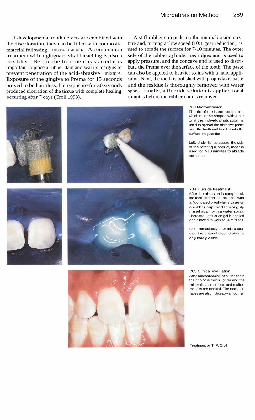
Microabrasion Method
289
If developmental tooth defects are combined withthe discoloration, they can be filled with compositematerial following microabrasion. A combinationtreatment with nightguard vital bleaching is also apossibility. Before the treatment is started it isimportant to place a rubber dam and seal its margins toprevent penetration of the acid-abrasive mixture.Exposure of the gingiva to Prema for 15 secondsproved to be harmless, but exposure for 30 secondsproduced ulceration of the tissue with complete healingoccurring after 7 days (Croll 1993).
A stiff rubber cup picks up the microabrasion mix-ture and, turning at low speed (10:1 gear reduction), isused to abrade the surface for 7-10 minutes. The outerside of the rubber cylinder has ridges and is used toapply pressure, and the concave end is used to distri-bute the Prema over the surface of the tooth. The pastecan also be applied to heavier stains with a hand appli-cator. Next, the tooth is polished with prophylaxis pasteand the residue is thoroughly removed with waterspray. Finally, a fluoride solution is applied for 4minutes before the rubber dam is removed.
783 MicroabrasionThe tip of the hand applicator,which must be shaped with a burto fit the individual situation, isused to spread the abrasive pasteover the tooth and to rub it into thesurface irregularities.
Left: Under light pressure, the sideof the rotating rubber cylinder isused for 7-10 minutes to abradethe surface.
784 Fluoride treatmentAfter the abrasion is completed,the teeth are rinsed, polished witha fluoridated prophylaxis paste ona rubber cup, and thoroughlyrinsed again with a water spray.Thereafter, a fluoride gel is appliedand allowed to work for 4 minutes.
Left: Immediately after microabra-sion the enamel discoloration isonly barely visible.
785 Clinical evaluationAfter microabrasion of all the teeththeir color is much lighter and themineralization defects and malfor-mations are masked. The tooth sur-faces are also noticeably smoother.
Treatment by T. P. Croll

29 0
Bleaching of Teeth
Nightguard Vital Bleaching
Carbamide peroxide solution, which corresponds to a3% hydrogen peroxide and 7% urea solution, is used tobleach individual teeth or entire groups of teeth. A 6%or 10% carbamide peroxide gel is also recommended.This uses a resin polymer of high molecular weight toincrease the viscosity and reduce diffusion during thenight. Depending upon the cooperation of the patient,the whitening of the teeth begins after 2-3 weeks andis completed after 5-6 weeks (Haywood 1992).
This home bleaching technique is indicated forexternal stains such as coffee, tea, or tobacco. Internal
discolorations can also be treated by using this methodin combination with other bleaching techniques.Bleaching may even be desirable for age-relatedchanges in tooth color. Because the bleaching solutionis allowed to work all night, questions naturally ariseconcerning its biological safety and possible damage tothe marginal gingiva. Woolverton et al. (1991) demon-strated that the solution is not mutagenic and elicitsonly a slight toxic reaction from isolated cells.
786 MicroabrasionA young female patient with gen-eralized brown and white mineral-i zation defects. The patient wasespecially unhappy with the ap-pearance of the maxillary anteriorteeth.
Right: Because the discoloration isl ocated deeper within the enamel,the teeth are microabraded beforeattempting bleaching with a mouth-piece.
787 Fabrication of the mouth-pieceA stone cast is made from an im-pression, and on this a mouthpiecei s vacuum-formed. The margins ofthe mouthpiece are then smoothed.
788 Bleaching gelThe bleaching gel is placed intothe mouthpiece by the patient. It isi mportant that the gel is placedonly in the regions to be bleachedand that it is applied sparingly. Ifthe mouthpiece is to be worn allday, the gel should be changedevery 2-3 hours.
Right: There are a number of vitalbleaching agents, besides car-bamide bleaching gel, that can beused either in a similar manner oras a tooth cream without a tray.

Nightguard Vital Bleaching
291
Before bleaching, the teeth are cleaned and a stonecast is made from an alginate impression. On the cast,resin spacers are placed on the labial surfaces of theteeth that are to be bleached. These are brought nocloser than 0.5 mm to the gingival margins to preventirritation. A thin, soft mouthpiece is then vacuum-formed over the cast. At the following appointment themouthpiece is first tried and the patient is instructedhow to wear it. After evening toothbrushing the patientplaces a small amount of the gel inside the mouthpiece,seats it slowly over the teeth, and removes the excess
gel with a cotton swab or a toothbrush. If the mouth-piece is worn only at night, treatment may require 4-6weeks. If the bleaching tray is also worn all day and thesolution or gel is changed every 2-3 hours, maximumwhitening can be achieved in only 7-10 days.
In a study by Haywood (1991) a success rate of 91 %is reported for this bleaching method. In 66% of the testsubjects, slight gingival irritation appeared and it wasnecessary to interrupt treatment for 1-2 days(Haywood et al. 1992).
789 Gel spacersSpacers are placed on the casts ofthe teeth to be bleached to createspaces for the bleaching gel. Thespacers should be placed no clos-er than 0.5 mm from the gingiva sothat the gel will not irritate themucosa. If the gingivae do becomei nflamed, bleaching should bei nterrupted for 2 days.
790 InsertionAfter the mouthpiece is lined withbleaching gel it is slipped over theteeth to be bleached with gentle,uniform pressure. Any overflowinggel is then removed with a cottonswab or a toothbrush.
791
Duration of treatmentThe teeth are significantly lighterafter 3 weeks of combined treat-ment. The mouthpiece is worn dayand night. The clinical photographshows the persisting results 8months after completion of treat-ment.
Treatment by T. P. Croll

292
Bleaching of Teeth
792 Clinical resultsLeft: Severe discoloration andsuperficial enamel defects as aresult of multiple fluoride applica-tions in an 11-year-old child. Thetwo central incisors were micro-abraded and then further bleachedwith carbamide peroxide gel for 21days.
Right: One year after treatment thetwo teeth no longer exhibit thebrownish discoloration.
793 Clinical resultsLeft: The upper central incisors ofthis 13-year-old girl were not asseverely discolored as in theprevious case. They were alsobleached by the combined tech-niques.
Right: Six months after treatmentthe discoloration is still gone andthe teeth are clearly whiter.
794 Treatment relapseLeft: Three years before this photo-graph was taken, the four maxillaryi ncisors were treated by microabra-sion because the patient had gene-ralized white demineralization. Theteeth subsequently assumed a lightyellow coloration.
Right: Six months after a 21-day-l ong vital bleaching procedurewith carbamide peroxide, all themaxillary teeth are harmonious incolor.
795 Partial successLeft: Severe defective mineraliza-tion of the enamel with brown andwhite spots in a 14-year-old girl.
Right: Fifteen months after micro-abrasion followed by the night-guard vital bleach method andimproved oral hygiene, the teethappear lighter and the brown dis-colorations are gone.
Treatment by T. P. Croll

293
References
The flood of new literature in the field of endodonticsis continuously increasing. For the dental practitioner,and even for the specialist, it is hardly possible tosurvey it all. The authors have attempted to documentas thoroughly as possible the originators of the clinicaland scientific innovations described in the text. The
list below makes no pretext of being all-inclusive,however. There are not only many historical works butalso newer publications that remain unmentioned. Acomprehensive list of references will gladly be madeavailable by the authors upon request.
A
Abou-Bass,
M.,
Frank, A. L.,
Glick,
D. H.: The
anticurvature
filingmethod to prepare the curved root canal. J. Am. Dent. Assoc. 101: 792,1980.Abou-Rass, M.: The elimination of tetracycline discoloration byi ntentional endodontics and internal bleaching. J. Endodont. 8: 101,1 982.Abou-Rass, M., Piccinino, M.: The effectiveness of four clinical irrigationmethods on the removal of root canal debris. Oral Surg. 54: 323, 1982.Abou-Rass, M.: Cracked lines: the precursors of tooth fractures-theirdiagnosis and treatment. Quintessence Int. 14: 437, 1983.Adloff, P: Das Durchsichtigmachen von Zahnen and unsere Wurzel-fullungsmethoden. Dtsch. Monatsschr. Zahnheilkd. 31: 445, 1913.Alhadainy, H. A.: Root perforations. A review of literature. Oral. Surg. 78:368, 1994.Akpata, II Blechman, H.: Bacterial invasion of pulpal dentinal wall invitro. J. Dent. Res. 61: 435, 1982.Aktener, B.O., Bilkay, U.: Smear layer removal with different concentra-ti ons of EDTA-ethylebamine mixtures. J. Endodont. 19: 228, 1993.AI-Nazhan, S., Andreasen, J.O., AI-Bawardi, S., AI-Rouq, S.:Evaluation of the effect of delayed management of traumatized per-manent teeth. J. Endodont. 21: 391, 1995.Allen, R. K., Newton, C. W., Brown, C.E.: A statistical analysis of surgicaland nonsurgical endodontic retreatment cases. J. Endodont. 15: 261,
1 989.Altonen, M., Mattila, K.: Follow-up study of apicoectomized molars. Int.J. Oral Surg. 5: 33, 1976.Andersen, M., Lund, A., Andreasen, J.O., Andreasen, FM.: In vitrosolubility of human pulp tissue in calcium hydroxide and sodiumhypochlorite. Endodont. Dent. Traumatol. 8: 104, 1992.Ando, N., Hoshino, E.: Predominant obligate anaerobes invading thedeep layers of root canal dentine. Int. Endodont. J. 23: 20, 1990.Andreasen, F, Vestergaard, B.: Prognosis of luxated permanent teeth -the development of pulp necrosis. Endodont. Dent. Traumatol. 1: 207,1 985.Andreasen, F, Zihjie, Y., Thomsen, B.: Relationship between pulpdimensions and development of pulp necrosis after luxation injuries inthe permanent dentition. Endodont. Dent. Traumatol. 2: 90, 1986.Andreasen, G. F, Hilleman, T. B.: An evaluation of 55-cobalt substitutedNitinol wire for use in orthodontics. J. Am. Dent. Assoc. 82: 1373, 1971.
Andreasen, J. O.: Luxation of permanent teeth due to trauma. Scand. J.Dent. Res. 78: 273, 1970.Andreasen, J.O.: Challenges in clinical dental traumatology. Endodont.Dent. Traumatol. 1: 45, 1985.Andreasen, J. O.: Traumatologie der Zahne. Schlutersche Verlagsanstalt,Hannover 1988.Andreasen, J.0., Borum, M. K., Jacobsen, H. L., Andreasen, F. M.:Replantation of 400 avulsed permanent incisors. Endodont. Dent.Traumatol. 11: 51, 1995.Arens, D. E., Rich, J. J., Healey, H.J.: A practical method of bleachingtetracycline-stained teeth. Oral Surg. 34: 812, 1972.Armitage, G.C., Ryder, M.I., Wilcox, S.E.: Cemental changes in theteeth with heavily infected root canals. J. Endodont. 9: 127, 1983.Arrastia, A. M., Wilder-Smith, P, Berns, M. W.: Thermal effects of C0 2l aser pulpotomy on human primary teeth. J. Dent. Res. 7 3 (Spec. Iss.318): Abstr. 1734, 1994.
B
Bahcall, J., Howard, P, Miserendino, L., et al.: Preliminary investigationof the histological effects of laser endodontic treatment on the periradi-cular tissues in dogs. J. Endodont. 18: 47, 1992.Baker Dirk, O.: Posteruptive changes in dental enamel. J. Dent. Res. 4 5(Suppl. 3): 503, 1986.Barnett, F, Trope, M., Khoja, M., Tronstad, L.: Bacteriologic status ofroot canal after sonic, ultrasonic and hand instrumentation. Endodont.Dent. Traumatol. 1: 228, 1985.Baumann, M.A., Appel, T., Zick, K.: New insights into dental anatomyusing NMR-microscopy. Eur. Microsc. Analys. 25: 7, 1993a.Baumann, M.A., Doll, G.M., Zick, K.: Stray-field imaging (STRAFI) ofteeth. Oral Surg. 75: 517, 1993b.Baumann, M.A., GroB, D., Lehmann, V., Zick, K.: Magnetresonanz-mikroskopie - Neue Perspektiven fur die Endodontie. Schweiz.Monatsschr. Zahnmed. 103: 1407, 1993c.Baumann, M.A., Schwebel, T., Kriete, A.: Dental anatomy portrayedwith microscopic volume investigations. Comput. Med. Imaging Graph.
1 7:221,1993d.Baumann, M.A.: A new approach to demonstration of root canalanatomy. J. Dent. Educ. 58: 704, 1994a.Baumann, M., Beer, R.: Der endodontische Notfall. Zahnarztl.Welt/Refor m 1 03: 584, 1994b.

29 4 References
Baumann, M.A., Scharf, H.: Moderne Bildverarbeitungsverfahren alsUnterstutzung der raumlichen Rekonstruktion histologischer Strukturen.Anat. Anz. 176: 185, 1994c.Baumann, M.A.: Die raumliche Darstellung des Endodonts. Hanser,Munchen 1995.Baumann, M.A., Gerhards, F: Die retrograde Wurzelkanalfullung.Quintessenz 47: 1463, 1996.Baumann, M.A., Roth, A.: Effect of experience on quality of canalpreparation with rotary nickel-titanium files. Oral Surg Oral Med OralPathol Oral Radiol Endod, 1999 (in press).Baumann, M. A., Doll. M. A.: Spatial
reproduction of the root canalsystem by magnetic resonance microscopy. J. Endodont 23: 49, 1997.Baume, L.J., Conne, F, Fiore-Donno, G.: L'etat de la pulpe sous lacarie dentaire et ses consequences therapeutiques. Rev. Fr. Odonto-stomatol. 4: 511, 1970.Baume, L.J.: The Biology of Pulp and Dentine. A Historic, Terminologic-Taxonomic, Histologic-Biochemical, Embryonic and Clinical Survey.Monographs in Oral Science, Vol. 8. Karger, Basel 1980.Baumgartner, J. C., Mader, C. L.: A SEM evaluation of four root canali rrigation regimens. J. Endodont. 13: 147, 1987.Baumgartner, J.C., Falkner, W.A.: Bacteria in the apical 5 mm ofi nfected root canals. J. Endodont. 17: 380, 1991.Baumgartner, J. C., Cuenin, P .R.: Efficacy of several concentrations ofsodium hypochlorite for root canal irrigation. J. Endodont. 18: 605, 1992.Beaudry, R.J.: Prevention of rubber dam hypersensitivity. J. Endodont.1 0: 544, 1984.Beckham, B. M., Anderson, R. W., Morris, C. F: An evaluation of threematerials as barriers to coronal microleakage in endodontically treatedteeth. J. Endodont. 19: 388, 1993.Beer, R., Gangler, P: Reaktionen des Endodonts bei Initialkaries - einehistopathologische Studie. Dtsch. Stomatol. 36: 491, 1986.Beer, R., Gangler, R, Beer, M.: In-vitro Untersuchungen unterschied-l i cher Wurzelkanalfulltechniken and -materialien. Zahn Mund Kieferheilkd.74:800,1986a.Beer, R., Gangler, P, Benkert, O.: Zur Entstehung and Klassifikationi ntrapulpaler Dentinbildungen. Zahn Mund Kieferheilkd. 74: 675, 1986b.Beer, R., Gangler, P: Rasterelektronenmikroskopische Untersuchungenzur Effektivitat unterschiedlicher Wurzelkanalspullosungen. Zahn MundKieferheilkd. 75: 476, 1987.Beer, R., Gangler, R, Rupprecht, B.: Investigation of the canal spaceoccupied by gutta-percha following lateral and thermomechanicalcondensation. Int. Endodont. J. 20: 271, 1987.Beer, R., Keitel, S., Gangler, P, Wutzler, P, Pfister, W.: Biologische andmikrobiologische Prufung chlorhaltiger Wurzelkanalspullosungen. Dtsch.Stomatol. 38: 513, 1988a.Beer, R., Wutzler, P, Gangler, P, Pfister, W.: Vergleichende biologischeand mikrobiologische Prufung von Wurzelkanalfullmaterialien. ZahnMund Kieferheilkd. 76: 473, 1988b.Beer, R.: Vergleichende biologische Prufung zahnarztlicher Fullungs-materialien. Med. HabiIitationsschrift, Erfurt 1989.Beer, R., Gangler, P: Rasterelektronenmikroskopische Untersuchung derWurzelkanalaufbereitung mit Ultraschall. Dtsch. Zahnarztl. Z. 44: 334,1989.Beer, R., Gangler, P, Krehan, F, Wutzler, P: Das Dentinbond ingmaterialScotchbond in der biologischen Testkette - ist eine haftvermittelndeComposite-Fullungstechnik pulpavertraglich? Zahn Mund Kieferheilkd.77:243,1989.Beer, R., Gangler, P, Wutzler, P, Krehan, F: Vergleichende biologischePrufung des Glasionomerzementes Ketac-Bond. Dtsch. Zahnarztl. Z. 45:202, 1990.Beer, R.: Biologische Prufung des Glasionomerzementes Ketac-Fil unterAnwendungsbedingungen. Zahnarztl. Welt/Reform 1 00: 756, 1991.Beer, R.: Optimale Wurzelkanalaufbereitung, welche Technik fuhrt zumZiel? Phillip J. 9: 261, 1992a.Beer, R.: Pathohistologische Grundlagen der Wurzelkanalbehandlung.Phillip J. 9: 69, 1992b.Beer, R.: Revision von MiBerfolgen in der Endodontie. Phillip J. 11: 531,1992c.Beer, R.: Die biologischen Eigenschaften von Wurzelkanalfullmaterialien.Zahnarztl. Praxis 44: 126, 1993a.Beer, R.: Prophylaxe in der Endodontie. Zahnarztl. Welt/Refor m 1 02: 596,1 993b.
Beer, R.: Maschinelle vs Hand instrumentation des Wurzelkanals: dasCanal master-System. Zahnarztl. Welt/Reform 1 02: 856, 1993c.Beer, R.: Glasionomerzemente - Biologisch unbedenkliche Fullungs-materialien? Quintessenz 45: 1073, 1994.Beer, R., Baumann, M.A.: Klinische Untersuchung der Guttapercha-wurzelkanalfullung mit Apexit als Sealer. Zahnarztl. Welt/Reform 1 03: 365,1 994a.Beer, R., Baumann, M.A.: Praktische Endodontie. Urban & Schwar-zenberg, Munchen 1994b.Beer, R.: Bleichen - ein zahnschonendes Verfahren zur Verbesserungder Asthetik. Quintessenz 46: 873, 1995.Beer, R., Mayerhofer, G.: Fortschritte in der Endodontie - Die operati-onsmikroskopgestutzte Wurzelkanalbehandlung. Quintessenz 46: 1437,1 995.Beer, R.: Kariesdiagnostik im Seitenzahnbereich. Quintessenz 47: 607,1 996a.Beer, R.: Biologische Einschatzung zahnarztlicher Fullungsmaterialien. InHeinenberg, B.J.: Innovationen fur die Zahnheilkunde, Teil 8. Spitta,Balingen 1996b.Beer, R.: Revision endodontischer MiBerfolge unter dem Operationsmi-kroskop. Zahnarztl. Welt/Refor m 1 05: 98, 1996c.Benjamin, K.A., Dowson, J.: Incidence of two root canals in humanmandibular incisor teeth. Oral Surg. 38: 122, 1974.Benkert, O., Beer, R., Gangler, P, Koch, I. L.: Biologisch-experimentelleUntersuchungen zahnarztlicher Fullungswerkstoffe im Anwendungstestam Hausschwein. Zahn Mund Kieferheilkd. 75: 555, 1987.Berbert, A., Filho, M. T., Ueno, A. H., Bramante, C. M., Ishikiriama, A.:The influence of ultrasound in removing intraradicular posts. Int.Endodont. J. 28: 100, 1995.Bergenholtz, G., Warfvinge, J.: Migration of leucocytes in the dentalpulp in response to plaque bacteria. Scand. J. Dent. Res. 90: 354, 1982.Berude, J. A., Hicks, L. M., Sauber, J. J., Li, S. H.: Resorption afterphysiologic and rigid splinting of replanted permanent incisors inmonkeys. J. Endodont. 14: 592, 1988.Biggs, J. T., Benenati, F W., Sabala, C. L.: Treatment of iatrogenic rootperforations with associated osseous lesions. J. Endodont. 14: 620, 1988.Bille, J., Thylstrup, A.: Radiographic diagnosis and clinical tissuechanges in relation to treatment of approximal carious lesions. CariesRes. 16: 1, 1982.Bimstein, E., Shteyer, A.: Dilated type of dense invaginatus in thepermanent dentition. J. Dent. Child. 43: 410, 1976.Black, G.V.: An investigation of the physical characters of the humanteeth in relation to their disease, and to practical dental operations,together with the physical characters of filling materials. Dent. Cosmos.37:353,1895.Black, G.V.: Descriptive Anatomy of the Human Teeth, 4th ed. White,Philadelphia 1902.Blinkhorn, A. S., Leggate, E. M.: An allergic reaction to rubber dam. Br.Dent. J. 156: 402, 1984.Block,
R. M.,
Lewis,
R. D.,
Hirsch, J., Coffey, J.,
Langeland,
K.:Systemic distribution of 14C-labeled paraformaldehyd incorporatedwithin formocresol following pulpotomies in dogs. J. Endodont. 9: 176,1 983.Block, R. M., Pascon, E. A., Langeland, K.: Paste technique retreatmentstudy: a clinical, histopathologic and radiographic evaluation of 50 cases.Oral Surg. 60: 75, 1985.Boussens, J., Ducomin, J.R: La microchirurgie dentaire (M.C.D.).Quintess. Int. 6: 1, 1982.Briseno, B. M., Wirth, R., Hamm, G., Standhartinger, W.: Efficacy ofdifferent irrigation methods and concentrations of root canal irrigationsolutions on bacteria in the root canal. Endodont. Dent. Traumatol. 8: 6,1 992Brock, H.: Geratekompendium Mikrochirurgie. Zeiss OberkochenProd uktmanagement Chirurgische Gerate, Oberkochem, 1988.Brown, D. C., Morre, B. K., Brown, C. E., Newton, C. W.: An in vitro studyof apical extrusion of sodium hypochlorite during endodontic canalpreparation. J. Endodont. 21: 587, 1995.Brown, G.: Factors influencing succesfull bleaching of discolored rootfilled tooth. Oral Surg. 20: 238, 1965.Buchanan, L. S.: Cleaning and Shaping the Root Canal System. In Cohen,S., Burns, R. C.: Pathways of the Pulp. Mosby, St. Louis, 1991 (p. 112).Burch, J.G., Hulen, S.: A study of the presence of accessory foraminaand the topography of molar furcations. Oral Surg. 38: 451, 1974

References 295
Buoncristiani, J., Seto, G. B., Caputo, A. A.: Evaluation of ultrasonic andsonic instruments for intraradicular post removal. J. Endodont. 20: 486,1 994.Bystrom, A., Claesens, R., Sundqvist, G.: The antibacterial effect ofcamphorated paramonochlorphenol, camphorated phenol and calcium-hydroxide in the treatment of infected root canals. Endodont. Dent.Traumatol. 1: 170, 1985.Bystrom, A., Sundqvist, G.: Bacteriologic evaluation of the efficiency ofmechanical root canal instrumentation in endodontic therapy. Scand. J.Dent. Res. 89: 321, 1981.Bystrom, A., Sundqvist, G.: Bacteriological evaluation of the effect of0,5% sodium hypochlorite in endodontic therapy. Oral Surg. 55: 307,1 983.
Caicedo, R., vonFraunhofer, J. A.: The properties of endodontic sealercements. J. Endodont. 14: 527, 1988.Calas, P, Rochd, T., Michel, G.: In vitro attachment of Streptococcussanguis to the dentin of the root canal. J. Endodont. 20: 71, 1994.Camp, L. R., Todd, M. J.: The effect of dowel preparation on the apicalseal of three common obturation techniques. J. Prosthet. Dent. 50: 664,1 983.Camps, J. J., Pertot, W. J.: Torsional and stiffness properties of nickel-titanium K files. Int. Endodont. J. 28: 239, 1995.Canalda, C., Pumarola, J.: Bacterial growth inhibition produced by rootcanal sealer cements with a calcium hydroxide base. Oral Surg. 68: 99,1 989.Capurro, M.A., Goldberg, F, Balbachan, L., Macchi, R. L.: Evaluationof the dimensional stability of different thermoplasticized gutta-perchafillings using simulated glass root canals. Endodont. Dent. Traumatol. 9:1 60, 1993.Carabelli, G.: Systematisches Handbuch der Zahnheilkunde. Braun-muller & Seidel, Wien 1844.Carr, G.: Microscope in endodontics. J. Calif. Dent. Assoc. 11: 55, 1992.Carr, G. B.: Surgical Endodontics. In Cohen, S., Burns, R.C.: Pathways ofthe Pulp. Mosby, St. Louis 1994 (p. 531).Carr, G. B.: Retreament. In: Cohen, S., Burns R.C., Pathways of the Pulp.7th ed., Mosby, St. Louis 1998 (p. 791).Chailertvnitkul, P, Saunders, W. P, Mackenzie, D.: The effect of smearl ayer on microbial coronal leakage of gutta-percha root fillings. Int.Endodont. J. 29: 242, 1996.Chohayeb, A.A.: Evaluation of the apical condensation of gutta-perchaby a tapered calibrated spreader/plugger. J. Endodont. 19: 167, 1993.Choksi,
S. K.,
Brady,
J. M.,
Dang,
D. H.,
Rao,
M. S.:
Detectingapproximal dental caries with transillumination: A clinical evaluation. J.Am. Dent. Assoc. 125: 1098, 1994.Chong, B.S., Pitt Ford, T. R.: The role of intracanal medication in rootcanal treatment. Int. Endodont. J. 25: 97, 1992.Cleen, M.J.H.: Richtlinien zur Restauration wurzelkanalbehandelterZahne. Endodontie 4: 289, 1994.Cohen, S., Burns, R.C.: Pathways of the Pulp, 6th ed. Mosby, St. Louis1 994.Colernen, C.L., Svec, T.A.: Analysis of Ni-Ti versus stainless steeli nstrumentation in resin simulated canals. J. Endod. 23: 232, 1997.Cooke, H.G., Cox, FL.: C-shaped canal configurations in mandibularmolars. J. Am. Dent. Assoc. 99: 836, 1979.Coolidge, E. D.: Clinical Pathology of Treatment of Dental Pulp. In DentalTherapeutics, 2nd ed. Lea & Febiger, Philadelphia 1946.Cooper, J. S., Bokmeyer, T. J., Bowles, W. H.: Penetration of pulpchamber by carbamid peroxide bleaching agents. J. Endodont. 18: 315,1 992.Corcoran, J. F, Zillich, R. M.: Bleaching of vital tetracycline stainedteeth. J. Mich. Dent. Assoc. 56: 340, 1974.Cotton, W. R., Siegel, R. L.: Human pulp response to citric acid cavitycleanser. J. Am. Dent. Assoc. 96: 639, 1978.Covino, B. G., Vasallo, H. G.: Local Anesthetics. Mechanism of Actionand Clinical Use. Grune & Stratton, New York 1977.Cragg, T. K.: The use of rubber dam in endodontics. J. Can. Dent. Assoc.38:376,1972.
Croll, T. P: Enamel microabrasion for removal of superficial discoloration.J. Esthet. Dent. 1: 14, 1989a.Croll, T. P: Enamel microabrasion: The technique. Quintess. Int. 20: 395,1 989b.Croll, T. P: Enamel microabrasion for removal of superficial dysminera-l i zation and decalcification defects. J. Am. Dent. Assoc. 120: 411, 1990.Croll, T. P: Enamel microabrasion followed by dental bleaching: a casereport. Quintess. Int. 23: 317, 1992.Croll, T. P, Kilian, C. M.: Zinc oxide-eugenol pulpotomy and stainlesssteel crown restoration of primary molar. Quintessence Int. 23: 383, 1992.Croll, T. P: Behandlung des Zahnschmelzes mit Mikroabrasion.Quintessenz, Berlin 1993.Croll, T. P: Tooth
bleaching for children and teens: a protocol andexamples. Quintess. Int. 25: 811, 1994.Cvek, M.: A clinical report on partial pulpotomy and capping withcalcium hydroxide in permanent incisors with complicated crownfractures. J. Endodont. 4: 232, 1978.Cvek, M., Lindvall, A. M.: External root resorption following bleaching ofpulpless teeth with oxygen peroxide. Endodont. Dent. Traumatol. 1: 56,1985.Cvek, M.: Prognosis of luxated non-vital maxillary incisors treated withcalcium hydroxide and filled with gutta-percha. Endodont. Dent.Traumatol. 8: 45, 1992.
D
Dang, D. A., Walton, R. E.: Vertical root fracture and root distortion: effectof spreader design. J. Endodont. 15: 294, 1989.Daublander, M.: Zahnarztliche Therapie bei Risikopatienten I. Quint-essenz 40: 741, 1989a.Daublander, M.: Zahnarztliche Therapie bei Risikopatienten II. Quint-essenz 40: 931, 1989b.Deardorf, K. A., Swartz, M. J., Newton, C. W., Brown, C. E.: Effect of rootcanal treatment on dentin permeability. J. Endodont. 20: 1, 1994.Debelian, G.J., Olsen, I., Tronstad, L.: Profiling of Propionibacteriumacnes recovered from root canal and blood during and after endodontictreatment. Endodont. Dent. Traumatol. 8: 248, 1992.Debelian, G.J., Olsen, I., Tronstad, L.: Bacteremia in conjunction withendodontic therapy. Endodont. Dent. Traumatol. 11: 142, 1995.Dederich,
D. N.,
K. L.
Zakariasen,
Tulip,
L.:
Scanning
electronmicroscopic analysis of canal wall dentin following Neodymium-Yttrium-Aluminium-Garnet laser irradiation. J. Endodont. 10: 428, 1984.DeDeus, O. D.: Frequency, location and direction of the accessorycanals. J. Endodont. 1: 361, 1975.Deemer, J. P, Tsaknis, P.J.: The effect of overfilled polyethylene tubei ntraosseous implants in rats. Oral Surg. 48: 358, 1979.Denis, R., Oft, K.H.R.: Kofferdam-Allergie - ein Fallbericht. Dtsch.Zahnarztl. Z. 48: 306, 1993.Donly, K.J., O'Neill, M., Croll, T.P: Enamel microabrasion: a micro-scopic evaluation of the ,abrosion effect`. Quintess. Int. 23: 175, 1992.Dow., P .R., Ingle, J. I.: Isotope determination of root canal failures. OralSurg. 8: 1100, 1955.Drake, D. R., Wiemann, A. H., Riviera, E. M., Walton, R. E.: Bacterialretention in canal walls in vitro: effect of smear layer. J. Endodont. 20: 78,
1 994.Driscoll, W. S., Herschel, S. H., Meyers, R. J.: Prevalence of dentalcaries and dental fluorosis in areas with optimal and above-optimal waterfluoride concentrations. J. Am Dent. Assoc. 107: 42, 1983.Duggins, L. D., Clay, J. R., van Himel, T., Dean, J. W.: A combinedendodontic retrofill and periodontal guided tissue regeneration techniquefor the repair of molar endodontic furcation perforation. Quintessence Int.25: 109, 1994.Drake D. R., Wiemann, A. H., Rivera, E. M., Walton, R. E.: Bacterialretention in canal walls in vitro: effect of smear layer. J. Endodont. 20: 78,
1 994.Dumsha, T., Hovland, E. J.: Pulpal prognosis following extrusive luxationi njuries in permanent teeth with closed apexes. J. Am. Dent. Assoc. 36:410, 1982.

29 6 References
Dwan, J. J., Glickman, G. N.: 2-D Photoelastic stress analysis of NiTi andstainless steel finger spreaders during lateral condensation. J. Endodont.21: 221, 1995.
E
Eguchi, D., Peters, D. D., Hollinger, J. O.: A comparison of the area ofthe canal space occupied by guttapercha following four gutta-perchaobturation techniques. J. Endodont. 11: 166, 1985.Ehrmann, E. H.: Konservative Behandlung groBer apikaler Lasionen. InGuldener, PH.A., Langeland, K.: Endodontologie, 2. Aufl. Thieme, 1987 (S.290).Einwag, J.: Die intraligamentare Anasthesie. Zahnarztl. Mitt. 75: 693,1 985.Ekstrand, K., Quist, V., Thylstrup, A.: Light microscopic study of theeffect of probing in occlusal surfaces. Caries Res. 21: 368, 1987.Ekstrand, K. R., Kuzmina, I., Bjorndal, L., Thylstrup, A.: Relationshipbetween external and histologic features of progressive stages of cariesin the occlusal fossa. Caries Res. 29: 243, 1995.Eleazer, P .D.: Lack of corrosion of stainless steel instruments in vivo byscanning electron microscope and microprobe analysis. J. Endodont. 17:346, 1991.Eriksen, H. M., Orstavik, D., Kerekes, K.: Healing of apical periodontitisafter endodontic treatment using three different root canal sealers.Endodont. Dent. Traumatol. 4: 114, 1988.Erlemeier, E. M.: Aktuelle Aspekte der intraligamentaren Anasthesie.Quintessenz 41: 471, 1990.
Frentzen, M.: Laseranwendungen in der Zahnerhaltung and Parodonto-l ogie - Eine Obersicht. Dtsch. Zahnarztl. Z. 49: 113, 1994.Friedman, S., Rotstein, I., Libfeld, H., Stabholz, A., Heling, I.:I ncidence of external root resorption and esthetic results in 58 bleachedpulpless teeth. Endodont. Dent. Traumatol. 4: 23, 1988.Friedman, S., Rotstein, I., Sharlev, S.: Bypassing gutta-percha rootfillings with automated device. J. Endodont. 15: 432, 1989.Friedman, S., Stabholz, A., Tamse, A.: Endodontic retreatment - caseselection and technique. J. Endodont. 16: 543, 1990.Friedman, S., Lustmann, J., Sharabany, V.: Treatment results of apicalsurgery in premolar and molar teeth. J. Endodont. 17: 30, 1991.Friedman, S., Moshonov, J., Trope, M.: Resistance to vertical fracture ofroots, previously fractured and bonded with glass ionomer cement,composite resin and cyanoacrylate cement. Endodont. Dent. Traumatol. 9:101, 1993.Fuad, A. F, Rivera, E. M., Krell, K. V.: Accuracy of the endex withvariations in canal irrigants and foramen size. J. Endodont. 18: 63, 1993a.Fuad, A. F, Walton, R. E., Rittman, B. R.: Healing of induced periapicallesions in ferret. J. Endodont. 19: 123, 1993b.Furseth, R., Mjor, I.A.: Electron microscopy of human coronal dentin -a methological study with emphasis on the aspiration of odontoblastnuclei. Acta Odontol. Scand. 27: 577, 1980.Fuss, Z., Szajkis, S., Tagger, M.: Tubular permeability to calciumhydroxide and to bleaching agents. J. Endodont. 15: 362, 1982.Fuss, Z., Rafaeloff, R., Tagger, M., Szajkis, S.: Intracanal pH changesof calcium hydroxide pastes exposed to carbon dioxide in vitro. J. End-odont. 22: 362, 1996.
G
F
Fabricius, L., Dahlen, G., 6hman, A. E., Mol1er, A. J. R.: Predominantindigenous oral bacteria isolated from infected root canals after variedti mes of closure. Scand. J. Dent. Res. 90: 134, 1982.Fairborne, D. R., McWalter, G. M., Montgomery, S.: The effect of fourpraparation techniques on the amount of apically extruded debris. J.Endodont. 13: 102, 1987.Fava, R.G.: The doubled flare technique: an alternative for biomecha-nical preparation. J. Endodont. 9: 76, 1983.Fischer, G.: Der heutige Stand der Wurzelbehandlung mit Rdcksicht aufdie feinere Anatomie menschlicher Wurzelkanale insbesondere amForamen apicale. Dtsch. Monatsschr. Zahnheilkd. 30: 81, 1912.Flaitz, C. M., Hicks, M.J., Silverstone, L. M.: Radiographic, histologicand electronic comparison of occlusal caries: An in vitro study. Pediatr.Dent. 8: 24, 1986.Fogel, B. B.: A comparative study of five materials for use in filling rootcanal spaces. Oral. Surg. 43: 284, 1977.Fogel, H. M.: Microleakage of posts used to restore endodonticallytreated teeth. J. Endodont. 21: 376, 1995.Foster, K. H., Kulild, J. C., Weller, R. N.: Effect of smear layer removal onthe diffusion of calcium hydroxide through radicular dentin. J. Endodont.19:136,1993.Frank, R. M., Voegel, J. C.: Ultrastructure of the human odontoblast andits mineralisation during dental caries. Caries Res. 14: 367, 1980.Frank, R. M., Nalbandian, J.: Development of Dentine and Pulp. InBerkovitz, B.K.B., Boyde, A., Frank, R. M., H6hling, H. J., Moxham, B. J.,Nalbandian, J., Tonge, C. H.: Teeth. Springer, Berlin 1989 (p. 73).Frank, R. M., Steuer, P, Hemmerle, J.: Ultrastructural study on humanroot caries. Caries Res. 23: 209, 1989.Freccia, W. F, Peters, D. D., Lorton, L., Bernier, W. E.: An in vitrocomparison of nonvital bleaching techniques in the discolored tooth. J.Endodont. 8: 70, 1982.Freedland, J. B.: Conservative reduction of large periapical lesions. OralSurg. 29: 455, 1970.Frentzen, M., Koort, H.J., Nolden, R.: Aufbereitung von Wurzelkanalenmit Excimer-Lasern. Dtsch. Zahnarztl. Z. 46: 288, 1991.
Gangler, P, Langeland, K.: Biologische Grundlagen der Endodontie.Zahn Mund Kieferheilkd. 69: 256, 1979.Galvan, D. A., Ciarlone, A. E., Pashley, D. H., Kulild, J. C., Primack,P .D., Simpson, M. D.: Effect of smear layer removal on the diffusionpermeability of human root. J. Endodont. 20: 83, 1994.Gambill, J. M., Alder, del Rio, C. E.: Comparison of nickel-titanium andstainless steel hand-file instrumentation using computed tomography. J.Endodont. 22: 369, 1996.Gatot, A., Arbelle, J., Leiberman, A., Yanai-Inbar, I.: Effects of sodiumhypochlorite on soft tissues after its inadvertent injection beyond the rootapex. J. Endodont. 17: 573, 1991.Gelfand, M., Goldman, M., Sunderman, E.J.: Effect of complete veneercrowns on the compressive strength of endodontically treated posteriorteeth. J. Prosthet. Dent. 52: 635, 1984.Georgopoulou, M., Kontakiotis, E., Nakou, M.: In vitro evaluation of theeffectiveness of calcium hydroxide and paramonochlorphenol onanaerobic bacteria from the root canal. Endodont. Dent. Traumatol. 9:249, 1993.Georgopoulou, M. K., Wu, M. K., Nikolaou, A., Wesselink, P .R.: Effectof thickness on the sealing ability of some root canal sealers. Oral Surg.80:338,1995.Geurtsen, W.: Die Kroneninfraktion posteriorer Zahne - klinischeMerkmale and Fallberichte. Int. J. Parodontol. Restaur. Zahnheilkd. 12:377, 1992.Gher, M. E., Dunlap, R. M., Anderson, M. H., Kuhl, L. V.: Clinical surveyof fractured teeth. J. Am. Dent. Assoc. 114: 174, 1987.Glosson, C. R., Haller, R. H., Dove, S. B., del Rio, C. E.: A comparison ofroot canal preparation using NiTi Hand, NiTi engine driven and K-Flexendodontic instruments. J. Endodont. 21: 146, 1995.Gluskin,
A. H.,
Radke,
R. A.,
Frost,
S. L.,
Watanabe,
L. G.:
Themandibular incisor: rethinking guidelines for post and core design. J.Endodont. 21: 33, 1995.Goerig, A. C., Michelich, R. J., Schultz, H. H.: Instrumentation of rootcanals in molars using the step-down technique. J. Endodont. 8: 550,1 982.Goldberg, F, Abramovich, A.: Analysis of the effect of EDTAC on thedentinal walls of the root canal. J. Endodont. 3: 101, 1977.Goldman, M., White, R. R., Moser, C. R., Tenca, J. I.: A comparison ofthree methods of cleaning and shaping the root canal. J. Endodont. 14:7, 1988.

References 29 7
Goldman, M., Laosonthorn, R, White, R. R.: Microleakage-full crownand the dental pulp. J. Endodont. 18: 473, 1992.Goldstein, R. E., Haywood, V. B., Heymann, H. O., Steiner, D. R., West,J.D.: Bleaching of Vital and Pulpless Teeth. In Cohen, S., Burns, R.C.:Pathways of the Pulp. Mosby, St. Louis, 1994.Grieve, A. R., Alani, A., Saunders, W. P: The effect on the dental pulp ofa composite resin and two dentin bonding agents and associatedbacterial microleakage. Int. Endodont. J. 24: 108, 1991.Grossman, L., Oliet, S., delRio, C.: Endodontic Practice, 11 th ed. Lea &Febiger, Philadelphia 1988.Grung, B., Molven, O., Halse, A.: Periapical surgery in a Norwegiancounty hospital: follow up findings of 477 teeth. J. Endodont. 16: 411,1 990.Guldener, RH.A., Langeland, K.: Endodontologie. 3. Aufl. Thieme,Stuttgart 1993.Gutierrez, J. H., Villena, F, Gigoux, C.: Microscopic and scanningelectron microscope examination of silver point corrosion caused byendodontic material. J. Endodont. 8: 301, 1982.Gutierrez, J. H., Herrera, V. R., Berg, E. H., Villena, F, Jofre, A.: The riskof intentional dissolution of the smear layer after mechanical preparationof root canals. Oral Surg. 70: 96, 1990a.Gutierrez, J. H., Jofre, A., Villena, F: Scanning electron microscopestudy on the bacteria action of endodontic irrigants on bacteria invadingthe dentinal tubules. Oral Surg. 69: 491, 1990b.Gutierrez,
J. H.,
Donoso,
E.,
Villena,
F,
Jofre,
A.:
Diffusion
ofmedicaments within root canal dentin. Oral Surg. 72: 351, 1991.Gutmann, J.L., Dumsha, T.C., Lovdahl, RE.: Problemlosungen in derEndodontie. Hanser, Munchen 1991.Gutman, J. L., Witherspoon, D. E.: Obturation
of the cleaned
andshaped root canal system. In: Cohen, S., Burns R.C., Pathways of thePulp. 7th ed., Mosby, St. Louis 1998 (p. 258).Gutmann, J.: Principles of endodontic surgery for the generalpractitioner. Dent. Clin. North Am. 28: 895, 1984.
H
Haapasalo, M., Orstavik, D.: In vitro infection and disinfection ofdentinal tubules. J. Dent. Res. 66: 1375, 1987.Haikel, Y., Frank, R. M., Voegel, J. C.: Scanning electron microscopy ofthe human enamel surface layer of incipient carious lesions. Caries Res.17: 1, 1983.Haikel, Y., Alleman, C.: Effectiveness of four methods of preparing rootcanals. J. Endodont. 14: 340, 1988.Haikel, Y., Gasser, P, Allemann, C.: Dynamic fracture of hybrid end-odontic hand instruments compared with traditional files. J. Endodont. 17:217, 1991.Hansen, E. K., Asmussen, E., Christiansen, N. C.: In vivo fractures ofendodontically treated posterior teeth restored with amalgam. Endodont.Dent. Traumatol. 6: 49, 1990.Hansen, S.R., Montgomery, S.: Effect of restoration thickness on thesealing ability of TERM. J. Endodont. 19: 448, 1993.Hardee, M., L. Miserendino, Kos, W.: Evaluation of the antibacterialeffects of intracanal Nd:YAG laser irradiation. J. Endodont. 16: 194, Abstr.20, 1990.Harrington, G., Natkin, E.: External resorption associated with bleachingof pulpless teeth. J. Endodont. 5: 344, 1979.Harrison, J.W., Jurosky, K.A.: Wound healing in the tissues of theperiodontium following periradicular surgery. J. Endodont. 17: 425, 1991.Harty, FJ.: Endodontics in Clinical Practice. Butterworth, London 1990.Hasselgren, G., Olsson, B., Cvek, M.: Effects of calcium hydroxide andsodium hypochlorite on the dissolution of necrotic porcine muscle tissue.J. Endodont. 14: 125, 1988.Hasselgren, G., Reit, C.: Emergency pulpotomy: pain relieving effectwith and without the use of sedative dressings. J. Endodont. 15: 254,
989.Hatton, J. F, Ferillo, R J., Wagner, G., Stewart, G. R: The effect ofcondensation pressure on the apical seal. J. Endodont. 14: 305, 1988.
Hawkins, R.W., Nii, C.T., Jacobsen, E.L., Murphy, R.A.: The smearlayer and bacterial penetration of radicular dentinal tubules. J. Endodont.20:196,1994.Haywood, V. B., Heymann, H. O.: Nightguard vital bleaching. Quintess.I nt. 20: 173, 1989.Haywood, V. B.: Overview and status of mouthguard bleaching. J. Esthet.Dent. 3: 157, 1991.Haywood, V. B., Heymann, H.O.: Nightguard vital bleaching: How safeis it? Quintess. Int. 22: 515, 1991.Haywood, V. B.: History, safety and effectiveness of current bleachingtechniques and applications of the nigthguard vital bleaching technique.Quintess. Int. 23: 471, 1992.Haywood, V. B., Lonard, R. H., Nelson, C.F.: Effectiveness of nightguardvital bleaching. J. Dent. Res. 71: 179, 1992.Healy, M.J.R.: The mathematics. Br. J. Oral Maxillofac. Surg. 22: 330,1 984.Heidemann, D., Ramil-Diwo, M.: Die Wurzelkanalfulltechniken miterwarmter Guttapercha: McSpadden-Technik, Endotec, vertikale Konden-sation, Ultrafil. In APW (Hrsg.): Endodontie: Neue Erkenntnisse aus Praxisand Wissenschaft. Hanser, Munchen 1993 (S. 107).Heithersay, G.S.: Calcium hydroxide in the treatment of pulpless teethwith associated pathology. J. Br. Endodont. Sec. 8: 74, 1975.Heling, I., Chandler, N. P: The antibacterial effect within dentinal tubulesof four root canal sealers. J. Endodont. 22: 257, 1996.Hembrough, J. H., Weine, F S., Pisano, J. V., Eskoz, N.: Accuracy of anelectronic apexlocator: a clinical evaluation in maxillary molars. J. End-odont. 19: 242, 1993.Hermann, B. W.: Calciumhydroxid als Mittel zum Behandeln and Fallenvon Wurzelkanalen. Med. Dissertation, Wurzburg 1920.Hess, W.: Zur Anatomie der Wurzelkanale, des menschlichen Gebissesmit Berucksichtigung der feineren Verzweigungen am Foramen apicale.HabiIitationsschrift, Zurich 1917.Hess, W.: Anatomy of the Root Canals of the Teeth of the PermanentDentition, Part I. Wood, New York 1925a.Hess, W.: The Anatomy of the Root Canals of the Teeth of the PermanentDentition. John Bale Sons & Danielson, London 1925b.Hession, R. W.: Endodontic morphology I - An alternative method ofstudy. Oral Surg. 44: 456, 1977a.Hession, R. W.: Endodontic morphology II - A radiographic analysis. OralSurg. 44: 610, 1977b.Hession, R. W.: Endodontic morphology III - Canal preparation. OralSurg. 44: 775, 1977c.Hession, R. W.: Endodontic morphology IV - A comparative study. OralSurg. 44: 915, 1977d.Hiltner, R. S., Kulild, J. C., Weller, R. N.: Effect of mechanical versusthermal removal of gutta-percha on the quality of the apical seal followingpost space preparation. J. Endodont. 18: 451, 1992.Ho, S., Goerig, A.C.: An in vitro comparison of different bleachingagents in the discolored tooth. J. Endodont. 15: 106, 1989.Horsted, P, Attar, K., Langeland, K.: Capping of monkey pulps withDycal and Ca-eugenol cement. Oral Surg. 52: 531, 1981.Holland, R., deSouza, V., Nery, M.J., deMelle, W., Bernabe, R F E.,Filho, J.A.O.: Reaction of rat connective tissue to gutta-percha andsilver points. Aust. Dent. J. 27: 224, 1982.Holland, R., Soares, I.J., Soares, I.M.: Influence of irrigation andi ntracanal dressing on the healing process of dogs teeth with apicalperiodontitis. Endodont. Dent. Traumatol. 8: 223, 1992.Holland, R., Alexander, A. C., Murata, S. S., dosSantos, C. A., Junior,E.D.: Apical leakage following root canal dressing with calcium hydroxide.Endodont. Dent. Traumatol. 11: 261, 1995a.Holland, R., Sakashita, M. S., Murata, S. S., Junior, E. D.: Effect ofdentine surface treatment on leakage of root fillings with glass ionomersealer. Int. Endodont. J. 28: 190, 1995b.Holmstrup, G., Palm, A.M., Lambjerg-Hansen, H.: Bleaching ofdicolored root-filled teeth. Endodont. Dent. Traumatol. 4: 197, 1988.Horiba, N., Maekawa, Y., Matsumoto, T., Nakamura, H.: A study of thedistribution of endotoxins in the dentin wall of infected root canals. J.Endodont. 16: 331, 1990.Howe, C. A., McKendry, D.J.: Effect of endodontic access preparation onresistance to crown root fracture. J. Am. Dent. Assoc. 121: 712, 1990.Huang, T. G., Schilder, H., Nathanson, D.: Effects of moisture contentand endodontic treatment on some mechanical properties of humandentin. J. Endodont. 18: 209, 1992.
298 References
Hulsmann, M.: Die endometrische Kanallangenbestimmung in derEndodontie - Indikation, Anwendung, Grenzen. Quintessenz 16: 1809,1 989.Hulsmann, M.: Das Auffinden zusatzlicher Wurzelkanale. Schweiz.Monatsschr. Zahnmed. 102: 84, 1992a.Hulsmann, M.: Das Canal-Finder-System - Wissenschaftliche Erkennt-nisse and klinische Erfahrungen. Endodontie 1: 45, 1992b.Hulsmann, M.: Die maschinelle Aufbereitung des Wurzelkanals. InSchriftenreihe APW. Endodontie: Neue Erkenntnisse aus Praxis andWissenschaft. Hanser, Munchen 1993a (S. 63).Hulsmann, M.: Guttapercha - Geschichte, Chemie, Eigenschaften andVerarbeitung. Endodontie 2: 115, 1993b.Hulsmann, M.: Endodontie. Thieme, Stuggart 1993c.Hulsmann, M.: Pramolaren mit drei Wurzelkanalen. Inzidenz, Diagnostikand Therapie. Endodontie 3: 277, 1994.Hulsmann, M.: Juristische Probleme in der Endodontie. Endodontie 4:93, 1995.Hulsmann, M.: Die Depotphorese - eine Standortbestimmung. End-odontie 5: 7, 1996a.Hulsmann, M.: Strategien zur Entfernung frakturierter Aufbereitungsin-strumente. Endodontie 5: 121, 1996b.Hulsmann, M.: Risiken and Nebenwirkungen bei der Devitalisierungpermanenter Zahne. Zahnarztl. Mitt. 86: 42, 1996c.Hulsmann, M.: Zur Geschichte der Wurzelkanalaufbereitung. Endodontie5:97,1996d.Hulsmann, M., Franz, B., Lorch, V.: Reproduzierbarkeit des periapicalprobability index (PRI). Zahnarztl. Welt/Reform 105: 366, 1996.Hulsmann, M., Rummelin, C., Schafers, F: Root canal cleanliness afterpreparation with different endodontic handpieces and hand instruments:a comparative SEM investigation. J. Endodont. 23: 301, 1997.
l e, Y. L., Verdonschot, E. H., Schaeken, M., vantHof, M. A.: Electricalconductance of fissure enamel in recent erupted molar teeth as relatedto caries status. Caries Res. 29: 94, 1995.I ngle, J. I.: Endodontics. Lea & Febiger, Philadelphia 1985.l oannides, C., Bortslap, W.A.: Apicoectomy on molars: a clinical andradiologic study. Int. J. Oral Surg. 12: 73, 1983.
J
Kaufman, A.Y., Keila, S.: Conservative treatment of root perforationusing apex locator and thermatic compactor. J. Endodont. 15: 267, 1989.Kazemi, R. B., Safavi, K. E., Spangberg, L.: Dimensional changes ofendodontic sealers. Oral Surg. 76: 766, 1993.Kazemi, R. B., Safavi, K. E., Spangberg, L.: Assessment of marginalstability and permeability of interim restorative endodontic material. OralSurg. 78: 788, 1994.Kazemi, R. B., Stenman, E., Spangberg, L.: The endodontic file is adisposable instrument. J. Endodont. 21: 451, 1995.Kehoe, J.C.: pH-reversal following in vitro bleaching of pulpless teeth. J.Endodont. 13: 6, 1987.Kerekes, K., Tronstad, L.: Long term results of endodontic treatmentperformed with a standardized technique. J. Endodont. 5: 83, 1979.Khayat, A., Lee, S.Y., Torabinejad, M.: Human saliva penetration ofcoronally unsealed obturated root canals. J. Endodont. 19: 458, 1993.Kiryu, T., Hoshino, E., Iwaku, M.: Bacteria invading periapicalcementum. J. Endodont. 20: 169, 1994.Klein, J., Wei, P, Shayegan, A., White, R., Goldman, P: Radiographicsuccess or failure compared with coronal restorations and radicularfilling. J. Endodont. 22: 191, 1996.Klimek, J., Kockapan, C., Borchert, J.: Haufigkeit and Qualitat vonWurzelkanalfullungen in den Jahren 1983 and 1991. Dtsch. Zahnarztl. Z.50:154,1995.Kockapan, C.: Elektronenmikroskopische Untersuchungen uber dieStruktur der Schmierschicht. Dtsch. Zahnarztl. Z. 42: 1028, 1987.Kockapan, C.: Die Bedeutung der Schmierschicht bei der Wurzelkanal-behandlung. Endodontie 4: 33, 1995.Kolokuris, I., Arvanitoyannis, I., Robinson, C., Blanshard, J.M.V.:Effect of moisture and aging on gutta-percha. J. Endodont. 18: 583, 1992.Kovarik, R. E., Breeding, L. C., Caughman, W. F: Fatigue life of threecore materials under simulated chewing conditions. J. Prosthet. Dent. 68:584, 1992.Krejci, I., Lohrer, C., Lutz, F: Modifizierte Kavitatenformen andTechniken fur mittelgroBe Kompositfullungen der Klasse II. Acta Med.Dent. Helv. 1: 96, 1996a.Krejci, I., Petrac, M., Lutz, F: Wear and marginal adaptation of resinreinforced glass ionomer class II restorations. Acta Med. Dent. Helv. 1:117,1996b.Kulild, J. C., Peters, D. D.: Incidence and configuration of canal systemsi n the root of maxillary first and second molars. J. Endodont. 16: 311,1 990.Kuttler, Y.: Microscopic evaluation of root apexes. J. Am. Dent. Assoc. 50:544, 1955.Kuwabara, R. K., Massler, M.: Pulpal reaction to active and arrestedcarious lesions. J. Dent. Child. 33: 190, 1966.Kvist, T., Rydin, E., Reit, C.: The relative frequency of periapical lesionsi n teeth with root canal retained posts. J. Endodont. 15: 578, 1989.
Jacobsen, E. L., Be Gole, E. A.: A comparison
of four root canalobturation methods employing gutta-percha. Endodont. Dent. Traumatol.8:206,1992.Jacobsen, I., Kerkes, K.: Long-term prognosis of traumatized permanentanterior teeth showing calcifying processes in the pulp cavity. Scand. J.Dent. Res. 85: 588, 1977.Jaquot, B. M., Panighi, M. M., Steinmetz, P, Sell, C.: Microleakage ofCavit, Cavit G and IRM by impedance spectroscopy. Int. Endodont. J. 29:256, 1996.Jerome, C. E., Hicks, L. M., Pelleu, G. B.: Compatibility of accessorygutta-percha cones used with two types of spreaders. J. Endodont. 14:428, 1988.Johnson, B.R., Remeikis, N.A.: Effective shelf-life of prepared sodiumhypochlorite solution. J. Endodont. 19: 40, 1993.Johnson, W. B.: A new gutta-percha technique. J. Endodont. 4: 184, 1987.
K
Kato, J., Hashimoto, M., Ono, H.: Pulp reactions after pulpotomy withNd:YAG laser i rradiation. J. Dent. Res. 70 (Spec. Iss. 384): Abstr. 943,1 991.
L
Lado, E.A., Stanley, H.R., Weisman, M.I.: Cervical resorption inbleached teeth. Oral Surg. 55: 78, 1983.Lake, F, ODell, N., Walton, R.: The effect of internal bleaching ontetracycline in dentin. J. Endodont. 11: 415, 1985.Langeland, K.: Tissue changes in the dental pulp. Odont. Tidskr. 65: 249,1 957.Langeland, K.: The histopathologic basis in endodontic treatment. Dent.Clin. North Am. 11: 491, 1967.Langeland, K., Dowden, W.E., Tronstad, L., Langeland, L. K.: HumanPulp Changes of latrogenic Origin. In Siskin, M.: The Biology of theHuman Dental Pulp. Mosby, St. Louis 1973 (p. 122).Langeland, K., Block, R. M., Grossman, L. I.: A histopathologic andhistobacteriologic study of 35 periapical endodontic surgical specimens.J. Endodont. 3: 8, 1977.Langeland, K., Cotton, W.: Recommended standard practices forbiological evaluation of dental materials. Int. Dent. J. 30: 140, 1980.Langeland, K.: Management of the inflamed pulp associated with deepcarious lesion. J. Endodont. 7: 169, 1981.

References 29 9
Lazarchik, D.A., Firestone, A. R., Heaven, T.J., Lussi, A.: Radiographicevaluation of occlusal caries: effect of training and experience. CariesRes. 29: 355, 1995.Lee, K.W., Lee, E.C., Poon, K.Y.: Palatogingival grooves in maxillaryi ncisor. Brit. Dent. J. 124: 14, 1968.Lee, Y. C., Yang, S. F, Hwang, Y. F, Chueh, L. H., Chung, K. H. C.:Microleakage of endodontic temporary restorative materials. J. Endodont.1 9: 516, 1993.Leisebach Minder, T., Hotz, RR.: Endodontie im Milchgebif3 and Fruh-stadium der bleibenden Dentition. In Guldener, P H.A., Langeland, K.:Endodontologie. 3. Aufl. Thieme, Stuttgart 1993 (S. 328).Leonardo, M. R., Almeida, W. A., Ito, I. Y., Bezerra da Silva, L. A.:Radiographic and microbiologic evaluation of posttreatment apical andperiapical repair of root canals of dogs teeth with experimentally inducedchronic lesions. Oral Surg. 78: 232, 1994.Leonardo, M. R., Almeida, W. A., Bezerra da Silva, L. A., Utrilla, L. S.:Histopathological observation of periapical repair in teeth withradiolucent areas submitted to two different methods of root canaltreatment. J. Endodont. 21: 137, 1995.Levy, G.: Une nouvelle instrumentation pour realiser mecaniquementl 'ensemble de la procedure endodontique: le canal finder. Rev. Fr. End-odont. 3: 11, 1984.Levy, G.: Interaction between silica and dentin during enlargement of a rootcanal with Nd:YAG laser beam during a fiber optic: A SEM investigation.I n Anderson, R.R., Katzir, A.: Proceedings of laser surgery. Advancedcharacterization, therapeutics, and systems III. SPIE 1643: 398, 1992.Liesenhoff, T., Lenz, H., Seiler, T.: Wurzelkanalaufbereitung mit Excimer-Laserstrahlen. Zahnarztl. Welt 98: 1034, 1989.Lilja, J., Nordenvall, K. J., Brannstrom, M.: Dentin sensitivity, odontob-lasts and nerves under dessicated or infected experimental cavities.Swed. Dent. J. 6: 93, 1982.Limkangwalmongkol, S., Burtscher, P, Abbott, P V., Sandier, A. B.,Bishop, B. M.: A comparative study of the apical leakage of four rootcanal sealers and laterally condensed gutta-percha. J. Endodont. 17:495, 1991.Lin, L., Langeland, K.: Innervation of the inflammatory periapical lesion.Oral Surg. 51: 535, 1981a.Lin, L., Langeland, K.: Light and electron microscopic study of teeth withcarious pulp exposures. Oral Surg. 57: 297, 1981b.Lin, L., Shovlin, P, Skribner, J., Langeland, K.: Pulp biopsies from theteeth associated with periapical radiolucency. J. Endodont. 10: 436, 1984.Lin, L.M., Pascon, E.A., Skribner, J., Gangler, R, Langeland, K.:Clinical, radiographic, and histologic study of endodontic treatmentfailures. Oral Surg. 11: 603, 1991.Lindauer, P A., Campbell, A. D., Hicks, M. L., Pelleu, G. B.: Vertical rootfractures in curved roots under simulated clinical conditions. J. Endodont.1 5: 345, 1989.Linn, J., Messer, H. H.: Effect of restorative procedures on the strength ofendodontically treated molars. J. Endodont. 20: 479, 1994.Lipp, M. D. W.: Die Lokalanasthesie in der Zahn-, Mund- and Kieferheil-kunde. Quintessenz, Berlin 1992.Lipp, M.D.W.: Notfalltraining fur Zahnarzte. 2. Aufl., SchlilterscheVerlagsanstalt, Hannover 1996a.Lipp, M. D. W.: Komplikationen bei der Lokalanasthesie. Merktafel. Schlu-tersche Verlagsanstalt, Hannover 1996b.Liu, H. H., Sidhu, S. K.: Cracked teeth treatment rationale and casemanagement: case report. Quintessence Int. 26: 485, 1995Lloyd, A., Thompson, J., Gutmann, J. L., Dummer, P M. H.: SealabiIityof the Trifecta technique in the presence or absence of a smear layer. Int.Endodont. J. 28: 35, 1995.Lumley, P J., Walmsley, A. D., Walton, R. E., Rippin, J. W.: Effect of pre-curving endosonic files on the amount of debris and smear layerremaining in curved root canals. J. Endodont. 18: 616, 1992.Lundy, T., Stanley, H.R.: Correlation of pulpal histopathology andclinical symptoms in human teeth. Oral Surg. 27: 187, 1969.Lussi, A.: Validity of diagnostic and treatment decision of fissure caries.Caries Res. 25: 296, 1991.Lussi, A.: Comparison of different methods for the diagnosis of fissurecaries without cavitation. Caries Res. 27: 409, 1993.Lussi, A., Nussbacher, U., Grosrey, J.: A novel non-instrumentedtechnique for cleansing the root canal system. J. Endodont. 19: 549,1 993.
Lussi, A., Firestone, A., Schoenberg, V., Hotz, P, Stich, H.: In vivodiagnosis of fissure caries using a new electrical resistance monitor.Caries Res. 29: 81, 1995a.Lussi, A., Hotz, P, Stich, H.: Die Fissurenkaries. Schweiz. Monatsschr.Zahnmed. 105: 1165, 1995b.Lussi, A., Messerli, L., Hotz, P, Grosrey, J.: A new non-instrumentaltechnique for cleaning and filling root canals. Int. Endodont. J. 8: 1, 1995c.Lutz, F, Krejci, I., Barbakow, F: Quality and durability of marginaladaptation in bonded composite restorations. Dent. Mater. J. 7: 107, 1991.
M
Macchi, R.L., Capurro, M. A., Herrera, C. L., Cebada, F R., Kohen, S.:I nfluence of endodontic materials on the bonding of composite resin tothe dentin. Endodont. Dent. Traumatol. 8: 26, 1992.Macko, D.J., Rutberg, M., Langeland, K.: Pulpal response to theapplication of phosphoric acid to dentin. Oral Surg. 45: 930, 1978.Madison, S., Walton, R. E.: Cervical root resorption following bleachingof endodontically treated teeth. J. Endodont. 16: 570, 1990.Magura, M. E., Kafrawy, A. H., Brown, C. E., Newton, C. W.: Humansaliva coronal microleakage in obturated root canals. J. Endodont. 17:324, 1991.Malamed, W. F: Handbook of Local Anesthesia. Mosby, St. Louis 1986.Mandel, E., Machtou, P, Torabinejad, M.: Clinical diagnosis andtreatment of endodontic and periodontal lesions. Quintess. Int. 24: 135,1 993.Marlin, J.: Injectable standard gutta-percha as a method of filling the rootcanal system. J. Endodont. 12: 354, 1986.Marsicovetere, E. S., Clement, D. J., delRio, C. E.: Morphometric videoanalysis of the engine driven Nickel-Titanium lightspeed instrumentsystem. J. Endodont. 22: 231, 1996.Marthaler, T. M., Germann, M.: Radiographic and visual appearance ofsmall smooth surface caries lesions studied on extracted teeth. CariesRes. 4: 224, 1970.Marthaler, T. M., Wiesner, V.: Rapidity of penetration of radiolucent areasthrough mesial enamel of first permanent molars. Helv. Odontol. Acta. 17:1 9, 1973.Martin, H.: Ultrasonic disinfection of the root canal. Oral Surg. 50: 566,976.
Martin, H., Cunningham, W.: The effect of endosonic and hand manipu-lation on the amount of root canal material extruded. Oral Surg. 53: 611,982.
Martin, H., Cunningham, W.: Endosonic endodontics: the ultrasoundsynergistic system. Int. Dent. J. 34: 198, 1984.Massler, M., Pawlack, J.: The affected and infected pulp. Oral Surg. 43:929, 1977.McCann, J. T., Keller, D. L., LaBounty, G. L.: Remaining dentin/cemen-tum thickness after hand or ultrasonic instrumentation. J. Endodont. 16:1 09, 1990.McInerney, S.T., Zillich, R.: Evaluation of internal sealing ability of threematerials. J. Endodont. 18: 376, 1992.Mc Spadden, J.T.: Self study course of the thermatic condensation ofguttapercha. Form no. 33410/80 USA, 1980.Meister, F, Lommel, T.J., Gerstein, H.: Diagnosis and possible causesof vertical root fracture. Oral Surg. 49: 243, 1980.Mejare, I., Cvek, M.: Partial pulpotomy in young permanent teeth withdeep carious lesions. Endod. Dent. Traumatol. 9: 238, 1993.Mejare, I., Malmgren, B.: Clinical and radiographic appearance ofproximal carious lesions at the time of operative treatment in youngpermanent teeth. Scand. J. Dent. Res. 94: 19, 1986.Melcer, J.: Apport du laser a C0 2 dans la sterilisation de certaines
i nfections d'origine dentaire. Rev. Stomatol. Chir. Maxillofac. 83: 146,1 982.Melcer, J., Chaumette, M.T., Melcer, F, et al.: Treatment of dentaldecay by C02 laser beam: preliminary results. Laser Surg. Med. 4: 311,1 984.Melcer, J., Chaumette, M.T., Melcer, F, et al.: Preliminary report on theeffect of the C0 2 laser beam on the dental pulp of the Macacca Mulattaprimate and the Beagle dog. J. Endodont. 11: 1, 1985.

300 References
Metzger, Z., Assif, O., Tamse, A.: Residual chloroform and plasticity incustomized gutta-percha master cones. J. Endodont. 14: 546, 1998.Metzler, R.S., Montgomery, S.: The effectiveness of ultrasonics andcalcium hydroxide for the debridement of human mandibular molars. J.Endodont. 15: 373, 1989.Meyer, W.: Die Darstellung der Wurzelkanale. Zahnarztl. Rdsch. 64: 532,1 955a.Meyer, W.: Die Probleme der sogenannten Gang ranbehandlung. Dtsch.Zahnarztl. Z. 10: 529, 1955b.Meyer, W.: Zu den anatomischen Grundlagen der Wurzelbehandlung.Dtsch. Zahnarztl. Z. 15: 777, 1960.Meyer, W.: Die Divertikel der Wurzelkanale. Dtsch. Zahnarztl. Z. 18: 520,1 963.Meyer, W.: Die Anatomie der Wurzelkanale, dargestellt an mikroskopi-schen Rekonstruktionsmodellen. Dtsch. Zahnarztl. Z. 25: 1064, 1970.Michanowicz, A., Czonstokowsky, M.: Sealing properties of ani njection-thermoplasticized low temperature (70°C) gutta-percha. Apreliminary study. J. Endodont. 10: 563, 1984.Mileman, P .A., Weele, L.T.: Accuracy in radiographic diagnosis. Dutchpractitioners and dental caries. J. Dent. Res. 18: 130, 1990.Miller, W.D.: Lehrbuch der konservierenden Zahnheilkunde. Thieme,Leipzig 1904.Milot, P, Stein, R. S.: Root fracture in endodontically treated teeth relatedto post selection and crown design. J. Prosthet. Dent. 68: 428, 1992.Miserendino, L.J.: Instruments, Materials and Devices. In Cohen, S.,Burns, R.C.: Pathways of the Pulp, 6th ed. Mosby, St. Louis 1994 (p. 377).Mitsis, F .J.: Flap operation technique for the treatment of certainendodontic and periodontic problems. J. Brit. Endod. Soc. 4: 6, 1970.Mjor, I.: Usage test for restorative materials. J. Endodont. 4: 308, 1978.Morfis, A.S.: Vertical root fractures. Oral Surg. 69: 631, 1990.Morgan, R. W., Carnes, D. L., Montgomery, S.: The solvent effects ofcalcium hydroxide irrigating solution on bovine pulp tissue. J. Endodont.1 7: 165, 1991.Morse, D. R., Esposito, J. V., Pike, C., Furst, M. L.: A radiographicevaluation of the periapical status of teeth treated by the gutta-percha -eucapercha method. Oral Surg. 56: 190, 1983.Moyer, P .W., Osetek, E. M., Ashkenaz, P, Gilbert, J. L.: Evaluation of asolvent softened gutta-percha obturation technique in curved canals.J. Endodont. 21: 459, 1995.MUller, H., Raab, W.H.M.: Temperaturabhangige Veranderungen derMikrozirkulation der Zahnpulpa. Dtsch. Zahnarztl. Z. 44: 496, 1989.Mungo, R., Richardson, J.: Use of the C0 2 l aser as a Non-Pharmacolo-gical Alternative to the Formocresol Vital Pulpotomy. A HistologicalComparison. In Powell, G.L.: Proceedings of the Third InternationalCongress on Laser in Dentistry. University of Utah Printing Services, Utah1993 (p.167).Myers, G. L., Montgomery, S.: A comparison of weights of debrisextruted apically by conventional filing and canal master techniques. J.Endodont. 17: 275, 1991.
Nguyen, T. N.: Obturation of the root canal system. In: Cohen, S., BurnsR.C., Pathways of the Pulp. 6th ed., Mosby, St. Louis 1994 (p. 219).Nichols, E.: Treatment of traumatic perforation of the pulp cavity. OralSurg. 15: 603, 1962.Noar, S. J., Smith, B. G. N.: Diagnosis of caries and treatment decision inapproximal surfaces of posterior teeth in vitro. J. Oral Rehabil. 17: 209,1990.Nordenram, A., Svardstrom, G.: Results of apicoectomy. Swed. Dent. J.63:593,1970.Nutting, E., Poe, G.: Chemical bleaching of discolored endodonticallytreated teeth. Dent. Clin. North Am. 11: 1967, 655.
Ohara, P .K., Torabinejad, M., Kettering, J.D.: Antibacterial effects ofvarious endodontic irrigants on selected anaerobic bacteria. Endodont.Dent. Traumatol. 9: 95, 1993.Oliet, S.: Single-visit endodontics: a clinical study: J. Endodont. 9: 147,
983.Olsson, B., Sliwkowski, A., Langeland, K.: Subcutaneous implantationfor the biological evaluation of endodontic materials. J. Endodont. 7: 355,
981.Onnink, P .A., Dvis, R. D., Wayman, B. E.: An in vitro comparison ofi ncomplete root fractures associated with three obturation techniques. J.Endodont. 20: 32, 1994.Orstavik, D., Kerekes, K., Eriksen, H. M.: Clinical
performance ofendodontic sealers. Endodont. Dent. Traumatol. 3: 178, 1987.Orstavik, D., Mjor, I.A.: Histopathology and X-ray microanalysis of thesubcutaneous tissue response to endodontic sealers. J. Endodont. 14: 13,
988.Orstavik, D., Haapsalo, M.: Disinfection by endodontic irrigants anddressings of experimentally infected dentinal tubules. Endodont. Dent.Traumatol. 6: 142, 1990.Orstavik, D.: Radiographic evaluation of apical periodontitis andendodontic treatment results: a computer approach: Int. Dent. J. 41: 89,
991.Orstavik, D., Kerekes, K., Molven, O.: Effects of extensive apical ream-i ng and calcium hydroxide dressing on bacterial infection duringtreatment of apical periodontitis. Int. Endodont. J. 24: 1, 1991.Orstavik, D., Mjor, I.A.: Usage test of four endodontic sealers in Macacafascicularis monkeys. Oral Surg. 73: 337, 1992.Orth, U.: Die chemisch-mechanische Wurzelkanalaufbereitung. Histo-rische Entwicklung der Wurzelkanalinstrumente, Spulmittel and Aufberei-tungsmethoden. Dissertation, Mainz 1995.
NP
Nair, P N. R., Sjogren, U., Krey, G., Sundquist, G.: Therapy resistantforeign body giant cell granuloma at the periapex of a root-filled humantooth. J. Endodont. 16: 589, 1990a.Nair, R.N.R., Sjogren, U., Krey, G., Kahnberg, K. E., Sundqvist, G.:I ntraradicular bacteria and fungi in root filled asymptomatic human teethwith therapy resistent periapical lesions. J. Endodont. 16: 580, 1990b.Nair, P N. R.: Eine neue Sicht der radikularen Zysten - sind sie heilbar?Endodontie 4: 169, 1995.Nakamura, M., Kawahara, H., Imai, K., Tomoda, S., Kawata, Y.: Longterm biocompatibility test of composite resins and glass ionomer cement.Dent. Mater. J. 2: 100, 1983.Neaverth, E.J., Burg, H.A.: Decompression of a large periapical cysticlesion. J. Endodont. 8: 175, 1982.Nerwich, A., Figdor, D., Messer, H. H.: pH changes in root dentin over a4-week period following root canal dressing with calcium hydroxide. J.Endodont. 19: 302, 1993.
Panitvisai, P, Messer, H.H.: Cuspal deflection in molars in relation toendodontic and restorative procedures. J. Endodont. 21: 57, 1995.Pascon, E.A., Introcaso, J.H., Langeland, K.: Development ofpredictable periapical lesion monitored by substraction radiography.Endodont. Dent. Traumatol. 3: 192, 1987.Pascon, E. A., Leonardo, R. M., Safavi, K., Langeland, K.: Tissuereaction to endodontic materials: methods, criteria, assessment andobservations. Oral Surg. 72: 222, 1991.Pashley, D. H., Tao, L., Boyd, L., King, G. E., Horner, J.A.: Scanningelectron microscopy of the substructure of smear layer in human dentine.Arch. Oral Biol. 33: 265, 1988.Pashley, D. H.: Clinical consideration of microleakage. J. Endodont. 16:70, 1990.Patterson, C. J. W.: Polydam - polythene sheet, a practical alternative torubber dam for patients allergic to rubber compounds. Int. Endodont. J.22:252,1989.

References 301
Pecora, G., Abbondenos, C.: The indications and advantages whenusing the operatory microscope in endodontic surgery. IAS 3: 47thannual section AAE April 25, 1990.Pecora, G., Andreana, S.: Use of dental operating microscope inendodontic surgery. Oral Surg. 75: 751, 1993.Peters, D. D., Baumgartner, J. C., Lorton, L.: Adult pulpal diagnosis. I.Evaluation of the positive and negative responses to cold and electricalpulp tests. J. Endodont. 20: 506, 1994.Peters,
L. B.:
Preparation
der
endodontischen
Zugangskavitat
andDarstellung der Kanale. Teil I: Schneidezahne and Eckzahne. Endodontie1: 57, 1992a.Peters,
L. B.:
Preparation
der
endodontischen
Zugangskavitat
andDarstellung der Kanale. Teil II: Pramolaren. Endodontie 1: 141, 1992b.Peters, L. B.:
Preparation
der endodontischen Zugangskavitat
andDarstellung der Kanale. Teil III: Obere Molaren. Endodontie 1: 225,1 992c.Peters,
L. B.:
Preparation
der
endodontischen
Zugangskavitat
andDarstellung der Kanale. Teil IV: Untere Molaren. Endodontie 1: 291,1992d.Pieper, K., Schurade, B.: Die Untersuchung mit der Kaltlicht-Diagnose-sonde. Eine Alternative zum Flugelbih-Status. Dtsch. Zahnarztl. Z. 42: 900,1 987.Pietrobon, N., Lehner, C. R., Scharer, P: Langzeitprovisorien in derKronen- and Bruckenprothetik. Schweiz. Monatsschr. Zahnmed. 106: 237,1996.Pineda, F, Kuttler, Y.: Mesiodistal and buccolingual roentgenographici nvestigation of 7275 root canals. Oral Surg. 33: 101, 1972.Pineda, F: Roentgenographic investigation of the mesiobuccal root ofthe maxillary first molar. Oral Surg. 36: 253, 1973.Pineda, F: Roentgenographic investigation of the mesiobuccal root ofthe maxillary first molar. J. Am. Dent. Assoc. 88: 119, 1974.Pinero, G. J., Kiatpongsah, S., Hutchins, M.O., Hoover, J.: The effectof endotoxins on the synthesis of connective tissue matrix components bypulp fibroblasts in vitro. J. Endodont. 9: 2, 1983.Pitt Ford, T. R., Torabinejad,
M.,
McKendry,
D. J.,
Hong, C. U.,Kariyawasam, S. P: Use of mineral trioxide aggregate for repair of furcalperforations. Oral Surg. 79: 756, 1995.Pitts, D. L., Williams, B. L., Morton, T. H.: Investigation of the role ofendotoxins in periapical inflammation. J. Endodont. 8: 10, 1982.Plasmans, P J. J. M., Welle, P R., Vijrehoef, M. M. A.: In vitro resistanceof composite resin dowel and cores. J. Endodont. 14: 300, 1988.Porkaew, P, Retief, D. H., Barfield, R. D., Lacefield, W. R., Soong, S.:Effect of calcium hydroxide paste as an intracanal medicament on apicalseal. J. Endodont. 8: 369, 1990.Portell, F R., Bernier, W. E., Lorton, L., Peters, D. D.: The effect ofi mmediate versus delayed dowel space preparation on the integrity of theapical seal. J. Endodont. 8: 154, 1982.Portmann, P, Lussi, A.: A comparison between a new vacuumobturation technique and lateral condensation: An in vitro study. J.Endodont. 20: 292, 1994.Pumarola, J., Berasategui, E., Brau, E., Canalda, C., deAnta, T. J.:Antimicrobial activity of seven root canal sealers. Oral Surg. 74: 216,1992.
Ravn, J. J.: Follow up study of permanent incisors with enamel dentinfractures after acute trauma. Scand. J. Dent. Res. 89: 355, 1981a.Ravn, J.J.: Follow up study of permanent incisors with enamel fracturesas a result of an acute trauma. Scand. J. Dent. Res. 89: 213, 1981 b.Ravn, J.J.: Follow up study of permanet incisors with complicatedfractures after acute trauma. Scand. J. Dent. Res. 90: 363, 1982.Ray, H. A., Trope, M.: Periapical status of endodontically treated teeth inrelation to the technical quality of the root filling and the coronalrestoration. Int. Endodont. J. 28: 12, 1995.Reddy, S. A., Hicks, M. L.: Apical extrusion of debris using two hand andtwo rotary instrumentation techniques. J. Endod. 24: 180, 1998.Rehman, K., Saunders, W. P, Foye, R. H., Sharkey, S. W.: Calcium iondiffusion from calcium hydroxide-containing materials in endodonticallytreated teeth. Int. Endodont. J. 29: 271, 1996.Reid, J. S., Callis, P .D., Patterson, C.J.W.: Rubber Dam in ClinicalPractice. Quintessence, London 1991.Richman, M.: Use of ultrasonics in root canal therapy and root resection.J. Dent. 12: 12, 1957.Rivera,
E. M., Williams,
K.:
Placement
of
calcium
hydroxide
i nsimulated canals: comparison of glycerin versus water. J. Endodont. 20:445, 1994.Roane, J., Sabala, C., Duncanson, M.: The balanced force conceptfor instrumentation of curved canals. J. Endodont. 11: 203, 1985.Robertson, W.D., Melfi, R.C.: Pulpal response to vital bleachingprocedures. J. Endodont. 6: 645, 1980.Rock, W. P, Grundy, M. C.: The effect of luxation and subluxation uponthe prognosis of traumatized incisors teeth. J. Dent. 9: 224, 1981.Ross, R. S., Nicholls, J. I., Harrington, G. W.: A comparison of strainsgenerated during placement of five endodontic posts. J. Endodont. 17:450, 1991.Rotstein, I., Friedman, S., Mor, C., Katznelson, J., Sommer, M., Bab, I.:Histological characterization of bleaching-induced external root resorptioni n dogs. J. Endodont. 17: 436, 1991.Rotstein, I., Friedman, S., Stabholz, A.: Endodontische Behandlungs-konzepte bei Zehnen mit entwicklungsbedingten MiBbildungen.Endodontie 1: 117, 1992.Rotstein, I., Zyskind, D., Lewinstein, I., Bamberger, N.: Effect of dif-ferent protective base material on hydrogen peroxide leakage duringi ntracoronal bleaching in vitro. J. Endodont. 18: 114, 1992.Rubinstein, R., Kim, S.: Results of 94 endodontic microsurgeries usingSuper EBA retrofill. AAE abstracts Vol. 22: 188, 1996.Ruddle, C.J.: Endodontic failures: The rationale and application ofsurgical retreatment. Rev. Odontol. Stomatol. 5: 17, 1988.Ruddle, C. J.: Dreidimensionale Wurzelkanalfullung. Endodontie 4: 7, 1995.Rudolphy, M.P, vanAmerongen, J. P, tenCate, J. M.: Radioopacities indentine under amalgam restorations. Caries Res. 28: 240, 1994.Rudolphy, M. P, vanAmerongen, J. P, Penning, C., tenCate, J. M.: Greydiscoloration and marginal fracture for the diagnosis of secondary cariesi n molars with occlusal amalgam restorations. Caries Res. 29: 371, 1995.Rupprecht, B., Beer, R., Beer, M., Rupprecht, P: Klinisch kontrollierteStudie zur Erfolgsbewertung der lateralen and thermomechanischenGuttaperchakondensation. Dtsch. Stomatol. 39: 83, 1989.Rutledge, R. E., Montgomery, S.: Effect of intracanal medicaments onthe sealing ability of TERM. J. Endodont. 16: 260, 1990.
RS
Raab, W.H.M.: Die Laser-Doppler-FluBmessung: Untersuchung zurMikrozirkulation der Zahnpulpa. Dtsch. Zahnarztl. Z. 44: 198, 1989.Raab, W.H.M., Muller, H.: Temperaturabhengige Verenderungen derMikrozirkulation der Zahnpulpa. Dtsch. Zahnarztl. Z. 44: 496, 1989.Raab, W.H.M.: Diagnose and Pathologie entzundlicher Pulpaerkran-kungen. In APW (Hrsg.): Endodontie. Hanser, Munchen 1993 (S. 9)Raiden, G. C., Gendelman, H.: Effect of dowel space preparation on theapical seal of root canal fillings. Endodont. Dent. Traumatol. 10: 109,1994.Rankine-Wilson, R. W., Henry, P: The bifurcated root canal in loweranterior teeth. J. Am. Dent. Assoc. 70: 1162, 1965.Rapp, E. L., Brown, C. E., Newton, C. W.: An analysis of success andfailure of apicoectomies. J. Endodont. 17: 508, 1991.
Safavi, K., Pascon, E.A., Langeland, K.: Evaluation of tissue reaction toendodontic materials. J. Endodont. 9: 421, 1983.Safavi, K.E., Horsted, P, Pascon, E.A., Langeland, K.: Biologicevaluation of the apical dentin chip plug. J. Endodont. 11: 18, 1985.Safavi, K. E., Dowden, W. E., Langeland, K.: Influence of delayedcoronal permanent restoration on endodontic prognosis. Endodont. Dent.Traumatol. 3: 187, 1987.Safavi, K. E., Spangberg, L., Langeland, K.: Smear layer removal onroot canal dentin tubule infection. J. Endodont. 15: 175, 1989.Safavi, K. E., Nichols, F .C.: Effect of calcium hydroxide on bacteriall i popolysaccharide. J. Endodont. 19: 76, 1993.

302 References
Sailer, F, Pajarola, G.G.: Orale Chirurgie. Farbatlanten der Zahn-medizin, Band 11, Thieme, Stuttgart 1996.Saunders, W. R, Saunders, E. M.: Coronal leakage as a cause of failurei n root-canal therapy. Endodont. Dent. Traumatol. 10: 105, 1994.Schafer, E., Gohring, C.: Untersuchungen zur Normierung von Wurzel-kanalinstrumenten and Guttaperchastiften. Endodontie 2: 269, 1993.Schafer, E., Tepel, J., Hoppe, W.: Vergleichende Untersuchungen vonWurzelkanalinstrumenten aus herkommlichem Stahl and Nickel-Titan-Legierungen. Endodontie 3: 185, 1994a.Schafer, E., Tepel, J., Hoppe, W.: Wurzelkanalinstrumente aus Nickel-Titan-Legierungen zur Wurzelkanalaufbereitung. Zahnarztl. Welt. 103: 90,1 994b.Schafer, E.: Das Instrumentarium zur manuellen Wurzelkanalaufbe-reitung. Teil 1: Wurzelkanalinstrumente aus EdelstahIlegierungen. End-odontie 4: 205, 1995a.Schafer, E.: Das Instrumentarium zur manuellen Wurzelkanalaufbe-reitung. Teil 2: Wurzelkanalinstrumente aus Titan leg ierungen. Endodontie4:305,1995b.Schafer, E.: Auswirkungen verschiedener Sterilisationsverfahren auf dieSchneidleistung von Wurzelkanalinstrumenten. Dtsch. Zahnarztl. Z. 50:
1 50, 1995c.Schiffer, E.: Das Instrumentarium zur manuellen Wurzelkanalaufbe-reitung. Endodontie 4: 205, 1995d.Schilder, H.: A New Concept in Instrument Design. In Cohen, S., Burns,R.C.: Pathways of the Pulp, 6th ed. Mosby, St. Louis 1994 (p. 386).Schilder, H.: Filling root canals in three dimensions. Dent. Clin. NorthAm. 11: 723, 1967.Schilder, H.: Cleaning and shaping the root canal. Dent. Clin. North Am.
1 8.269, 1974.Schrader, U., Granath, L. E.: Early reaction of intact human teeth tocalcium hydroxide following experimental pulpotomy and its significanceto the development of hard tissue barrier. Odontol. Rev. 22: 379, 1971.Schrader, U.: Effects of the calcium hydroxide-containing pulp cappingagents on pulp cell migration, proliferation and differentiation. J. Dent.Res. 64: 541, 1985 (Spec. issue).Schroeder, H. E.: Pathobiologie oraler Strukturen. Karger, Basel 1991 (S.117).
Scianamblo, M.J.: MiBerfolge nach Wurzelkanalbehandlung and derenRevision. Endodontie 2: 191, 1993.Sedgley, C. M., Messer, H. H.: Are endodontically treated teeth morebrittle? J. Endodont. 18: 332, 1992.Seghi, R.R., Denri, I.: Effects of external bleaching on indentation andabrasion characteristics of human enamel in vitro. J. Dent. Res. 71: 1340,1 992.Segura, A., Donly, K. J., Wefel, J. S.: The effect of microabrasion ondemineralization inhibition of enamel surface. J. Dent. Res. 72: 318, 1993.Seltzer, S., Bender, I. B., Smith, J., Freedman, 1., Nazimov, H.: End-odontic failures: an analysis based on clinical, roentgenographic, andhistologic findings. Oral Surg. 23: 500, 1967.Seltzer, S., Farber, P.A.: Microbiologic factors in endodontology. OralSurg. 78: 634, 1994.Shoji, S., Nakamura, M., et al.: Histological changes in dental pulpsi rradiated by C02 l aser: a preliminary report on lasers in pulpotomy. J.Endodont. 11: 379, 1985.Short, J. A., Morgan, L.A., Baumgartner, J. C.: A comparison of canalcentering ability of four instrumentation techniques. J. Endod. 23: 503,1 997.Shwartz, M., Grondahl, H. G., Pliskin, J., Boffa, J.: A longitudinal ana-l ysis from bite-wing radiographs of the rate of progression of approximalcarious lesions trough human dental enamel. Arch. Oral Biol. 29: 529, 1984.Sigurdson, A., Stancill, R., Madison, S.: Intracanal placement ofCa(OH) 2 : a comparison of techniques. J. Endodont. 18: 367, 1992.Silverstone, L. M.: Structure of carious enamel including the early lesion.Oral Sci. Rev. 3: 100, 1973.Simon, J.H.S.: Diagnostik and Behandlung C-formiger Wurzelkanale.Endodontie 2: 7, 1993a.Simon, J.H.S.: Der endodontische Behandlungserfolg in Abhangigkeitvon der Definition des Apex. Endodontie 2: 97, 1993b.Simon, S. T., Bhat, K. S., Francis, R.: Effect of four vehicles on the pH ofcalcium hydroxide and the release of calcium ions. Oral Surg. 80: 459,1 995.
Simons, J., Ibanez, B., Friedman, S., Trope, M.: Leakage after lateralcondensation with finger spreaders and D-11-spreaders. J. Endodont. 17:101, 1991.Siqueira, J. F, Goncalves, R. B.: Antibacterial activity of root canalsealers against selected anaerobic bacteria. J. Endodont. 22: 79, 1996.Skidmore, A. E., Bjorndal, A. M.: Root canal morphology of the humanmandibular first molar. Oral Surg. 32: 778, 1971.Snuggs, H. M., Cox, C. F, Powell, C. S., White, K. C.: Pulpal healing anddentinal bridge formation in an acidic environment. Quintessence Int. 24:501, 1993.Socransky, S. S., Haffajee, A. D., Goodson, J. M., Lindhe, J.: Newconcepts of destructive periodontal disease. J. Clin. Periodont. 11: 21, 1984.Soeno, K.: A roentgenological study of morphologic change of pulpcavity with aging of human lower first molar. Odontol. J. Nippon Dent.Univ. 64: 1389, 1977.Soltanoff, W.A.: A comparative study of single visit and the multiple visitendodontic procedure. J. Endodont. 4: 278, 1978.Sorensen, J.A., Martinoff, J.T.: Clinically significant factors in doweldesign. J. Prosthet. Dent. 52: 28, 1984a.Sorensen, J.A., Martinoff, J.T.: Intracoronal reinforcement and coronalcoverage: a study of endodontically treated teeth. J. Prosthet. Dent. 51:780,1984b.Sorensen, J.A., Martinoff, J.T.: Endodontically treated teeth as abut-ments. J. Prosthet. Dent. 52: 631, 1985.Sorensen, J. A., Engelman, M.J.: Ferrule design and fracture resistanceof endodontically treated teeth. J. Prosthet. Dent. 63: 529, 1990.Sornkul,
E.,
Stannard,
J. G.:
Strength
of
roots
before
and
afterendodontic treatment and restoration. J. Endodont. 18: 440, 1992.Spangberg, L.W.S., Barbose, S. V., Lavigne, G. D.: AH26 releasesformaldehyde. J. Endodont. 19: 596, 1993.Spangberg, L.W.S.: Endodontic Filling Materials. In Smith, D.C.,Williams, D.F: Biocompatibility of Dental Materials. CRC, Boca Raton1 982 (p. 213).Spasser, H. F: A simple bleaching technique using sodium perborate.N.Y. State Dent. J. 27: 332, 1961.Stabholz, A., Sela, M. N.: The role of oral microorganisms in the patho-genesis of periapical pathosis. J. Endodont. 9: 171, 1983.Stabholz, A., Friedman, S.: Endodontic retreatment-case selection andtechnique. Part 2. J. Endodont. 14: 607, 1988.Staehle, H. J., Pioch, T., Hoppe, W.: The alkalizing properties of calciumhydroxid compounds. Endodont. Dent. Traumatol. 5: 147, 1989.Staehle H. J.: Calciumhydroxid in der Endodontie. Endodontie 1: 19,1 992.Staehle, H. J.: Medikamentose Einlagen -Temporare Wurzelfullungen. Z.Stomatol. 90: 203, 1993.Staehle, H.J.: Endodontie im MilchgebifB. I n APW (Hrsg.): Endodontie.Hanser, Munchen 1993 (S. 135).Staehle, H.J., Spiess, V., Heinecke, A., Miiller, H.R: The effect of rootcanal filling materials containing calcium hydroxide on the alkalinity ofsoot dentin. Endodont. Dent. Traumatol. 11: 163, 1995.Stashenko, P, Yu, S. M., Wang, C. Y.: Kinetics of immune cell and boneresorptive responses to endodontic infections. J. Endodont. 18: 422,1992.Stenman, E., Spangberg, L.S.W.: Machining efficiency ofendodontic K-Files and Hedstroem Files. J. Endodont. 16: 375, 1990a.Stenman, E., Spangberg, L.S.W.: Machining efficiency of Flex-R, K-Flex, Trio-Cut, and S Files. J. Endodont. 16: 575, 1990b.Stuart, K. G., Miller, C. H., Brown, C. E., Newton, C. W.: The comparativeantimicrobial effect of calcium hydroxide. Oral Surg. 72: 101, 1991.Siibay, R. K., Suzuki, S., Suzuki, S.: Human pulp response after partialpulpotomy with two calcium hydroxide products. Oral Surg. 80: 330,1 995.Sundqvist, G., Johansson, E., Sjagren, U.: Prevalence of black-pig-mented Bacteroides species in root canal infections. J. Endodont. 15: 13,1989.Sundqvist, G.: Ecology of the root canal flora. J. Endodont. 18: 427,1992.Sundqvist, G.: Microbiology in endodontics. J. Endodont. 18: 427, 1992.Swanson, K., Madison, S.: An evaluation of coronal microleakage inendodontically treated teeth. J. Endodont. 13: 56, 1987.

References 303
T v
Tagger, M., Szajkis, S.: Revision of root canal fillings. J. Endodont. 16:338, 1990.Tamse, A., Littner, M. M., Kaffe, I., Moskona, D., Gavish, A.: Morpholo-gical and radiographic study of the apical foramen in distal roots ofmandibular molars. Part I. The location of the apical foramen on variousroot aspects. Int. Endodont. J. 21: 205, 1988.Tamse, A.: Atiologie, Diagnose and Behandlung vertikaler Wurzelfrak-turen bei endodontisch behandelten Zehnen. Endodontie 3: 175, 1994.Tani, Y., Kawada, H.: Effects of laser irradiation on dentin. I. Effect onsmear layer. Dent. Mater. J. 6: 127, 1987.Tavares, T., Soares, I. J., Silveira, N. L.: Reaction of rat subcutaneoustissue to implants of gutta-percha for endodontic use. Endodont. Dent.Traumatol. 10: 174, 1994.Tenland, T.: On Laser Doppler Flowmetry. Methods and MicrovascularApplications. Linkoping Studies in Science and Technology DissertationsNo. 83/ Linkoping University Medical Dissertations No. 136, Linkoping1 982.Testori, T., Badino, M., Castagnola, M.: Vertical root fractures inendodontically treated teeth: a clinically survey of 36 cases. J. Endodont.1 9; 87, 1993.Thylstrup, A., Bille, J., Quist, V.: Radiographic and observed tissuechanges in approximal carious lesions at the time of operative treatment.Caries Res. 20: 75, 1986.Titley, K. C., Torneck, C. D., Ruse, N. D.: The effect of carbamide-peroxide gel on the shear bond strength of a microfil resin to bovineenamel. J. Dent. Res. 71: 20, 1992.Tolksdorf, W.: Der preoperative Stref3. Springer, Berlin 1985.Torabinejad, M., Kettering, J. D., McGraw, J.D., Cummings, R.R.,Dwyer, T. G., Tobias, T.S.: Factors associated with endodontic interap-pointment emergencies of teeth with necrotic pulps. J. Endodont. 14: 261,1 988.Torabinejad, M., Ung, B., Kettering, J. D.: In vitro bacterial penetrationof coronally unsealed endodontically treated teeth. J. Endodont. 16: 566,1 990.Torneck, C. D.: Changes in the fine structure of the dental pulp in humancarious pulpitis.l. nerves and blood vessels. J. Oral Pathol. 3: 71, 1974.Torneck, C. D.: A report of studies into changes in the fine structure ofthe dental pulp in hurnian carious pulpitis. J. Endodont. 7: 8, 1981.Torneck, C. D., Titley, K. C., Smith, D. C., Adibfar, A.: Effect of waterl eaching on the adhesion of composite resin to bleached andunbleached bovine enamel. J. Endodont. 17: 156, 1991.Tronstad, L., Yang, Z. P, Trope, M., Barnett, F, Hammond, B. F:Controlled release of medicaments in endodontic therapy. Endodont.Dent. Traumatol. 1: 130, 1985.Trope, M., Tronstad, L.: Resistance to fracture of endodontically treatedpremolars restored with glass ionomer cement or acid etch compositeresin. J. Endodont. 17: 257, 1991.Trope, M., Ray, H.L.: Resistance to fracture of endodontically treatedroots. Oral Surg. 73: 99, 1992.Trope, M., Moshonov, R., Nissan, R., Buxt, P, Yesilsoy, J.: Short vsl ong term Ca(OH) 2 treatment of inflammatory root resorption. J. Endodont.20:196,1994.Trope, M., Chow, E., Nissan, R.: In vitro endodotoxin penetration ofcoronally unsealed endodontically treated teeth. Endodont. Dent.Traumatol. 11: 90, 1995a.Trope, M., Moshonov, J., Nissan, R., Buxt, P, Yesilsoy, C.: Short vsl ong-term calcium hydroxide treatment of established inflammatory rootresorption in replanted dog teeth. Endodont. Dent. Traumatol. 11: 124,
1 995b.Tsurumachi, T., Saito, T.: Treatment of large periapical lesions byi nserting a drainage tube into the root canal. Endodont. Dent. Traumatol.11: 41, 1995.Tveit, A. B., Espelid, I., Fjelltveit, A.: Clinical diagnosis of occlusal dentincaries. Caries Res. 28: 368, 1994.
Vahdaty, A., Pitt Ford, T. R., Wilson, R. F: Efficacy of chlorhexidine indisinfecting dentinal tubules in vitro. Endodont. Dent. Traumatol. 9: 243,1 993.Vanderas, A.P: Effects of intracanal medicaments on inflammatoryresorption or occurence of ancylosis in mature traumatized teeth. End-odont. Dent. Traumatol. 9: 175, 1993.Van der Burgt, T.P, Plasschaert, A.J.M.: Bleaching of tooth discolo-ration caused by endodontic sealers. J. Endodont. 12: 231, 1986.Van Winkelhoff, A. J., Kippuw, N., van Steenbergen, T.J.M., de Graaff, J.:Cross inhibition between black-pigmented Bacteroides species. J. Dent.Res. 66: 1663, 1987.Van Winkelhoff, A. J., van Steenbergen, T.J.M., de Graaff, J.: Porphy-romonas (Bacteroides) endodontalis: its role in endodontal infections. J.Endodont. 18: 431, 1992.Vassiliadis,
L. P,
Sklavounos,
S. A.,
Stavrianos,
C. K.:
Depthpenetration and appearance of Grossman sealer in the dentinal tubules:an in vitro studa. J. Endodont. 20: 373, 1994.Verdonschot, E. H., Rondel, P, Huysmans, M. C.: Validity of electricalconductance measurements in evaluating the marginal integrity ofsealant restorations. Caries Res. 29: 100, 1995.Vertucci, F.J.: Root canal anatomy of the mandibular anterior teeth. J.Am. Dent. Assoc. 89: 369, 1974.Vertucci, F J., Seelig, A., Gillis, R.: Root canal morphology of the humanmaxillary second premolar. Oral Surg. 38: 456, 1974.Vertucci, FJ., Williams, R.G.: Furcation canals in the humanmandibular first molar. Oral Surg. 38: 308, 1974.Vertucci, FJ.: Root canal morphology of mandibular premolars. J. Am.Dent. Assoc. 97: 47, 1978.Vertucci, FJ., Gegauff, A.: Root canal morphology of the maxillary firstpremolar. J. Am. Dent. Assoc. 99: 194, 1979.Vertucci, FJ.: Root canal anatomy of the human permanent teeth. OralSurg. 58: 589, 1984.Vertucci, F.J., Anthony, R. L.: A scanning electron microscopic investi-gation of accessory foramina in the furcation and pulp chamber floor ofmolar teeth. Oral Surg. 62: 319, 1986.Vire, D. E.: Failure of endodontically treated teeth, classification andevaluation. J. Endodont. 17: 338, 1991.Vof3, A.: Die Wurzelkanallengenbestimmung - Rontgenologisch and/oderendometrisch. In APW (Hrsg.): Endodontie. Hanser, Munchen 1993 (S.49).
W
Walia, H., Streiff, J., Gerstein, H.: Use of a hemostatic agent in therepair of procedural errors. J. Endodont. 14: 465, 1988.Walker, T. L., delRio, C.E.: Histological evaluation of ultrasonic and sonici nstrumentation of curved root canals. J. Endodont. 15: 49, 1989.Walton, R., Fouad, A.: Endodontic interappointment flare-ups: aprospective study of incidence and related factors. J. Endodont. 18: 172,1 992.Walton, E. E., Langeland, K.: Migration of materials of the dental pulpaof monkeys. J. Endodont. 4: 167, 1978.Walton, R. E., O'Dell, N. L., Myers, D. L., Lake, F .T., Shimp, R. G.:External bleaching of tetracycline stained teeth in dogs. J. Endodont. 8:536, 1982.Walton, R. E., Michelich, R. J., Smith, G. N.: The histopathogenesis ofvertical root fractures. J. Endodont. 10: 48, 1984.Webber, R.T., del Rio, C. E., Brady, J. M., Segall, R.O.: Sealing qualityof a temporary filling material. Oral Surg. 46: 123, 1978.Wechsler, S. M., Vogel, R. I., Fishelberg, G., Shovlin, RE.: latrogenicroot fractures. J. Endodont. 4: 251, 1978.Weichmann, J. A., Johnson, FM.: Laser use in endodontics, a prelimi-nary investigation. Oral Surg. 31: 416, 1971.Weine, F .S., Healey, H. J., Gerstein, H., Evanson, L.: Canal configu-ration in the mesio-buccal root of the maxillary fist molar and its end-odontic significance. Oral Surg. 28: 419, 1969.
304 References
Weine, F S.: Endodontic Therapy, 2nd ed. Mosby, St. Louis 1982.Weine, F S., Wax, A. H., Wenckus, C. S.: Retrospective study of tapered,smooth post systems in place for 10 years or more. J. Endodont. 17: 293,1991.Weine, FS.: Wurzelkanal-Fullungsmaterialien - ein Ausblick in das 21.Jahrhundert. Phillip J. 11: 227, 1994.Weine, S.W., Rice, R.T.: Handling previously treated silver point cases:removal, retreatment and tooth retention. Compend. Contin. Educ. Dent.7:652,1986.Weller, N., Niemczyk, S. P, Kim, S.: Incidence and position of the canalisthmus. J. Endodont. 21: 380, 1995.Weller, N. R., Kimbrough, W. F, Anderson, R. W.: Root surface tempera-tures produced during post space preparation. J. Endodont. 22: 304,1996.Wennberg, A., Orstavik, D.: Evaluation of alternatives to chloroform inendodontic practice. Endodont. Dent. Traumatol. 5: 234, 1989.Wenzel, A., Hintze, H., Mikkelsen, L., Mouyen, F: Radiographicdetection of occlusal caries in noncavitated teeth. Oral Surg. 72: 621,1 991.Wesselink, P .R.: Qualitatsrichtlinien endodontischer Behandlung.Endodontie 3: 263, 1994.West, J. D., Roane, J. B.: Cleaning and shaping the root canal system In:Cohen, S., Burns. R.C., Pathways of the Pulp, 7th ed., Mosby, St. Louis1998 (p. 203).White, S. C., Atchinson, K. A., Hewlett, E. R., Flack, V. F: Efficacy of FDAguidelines for ordering radiographs for caries detection. Oral Surg. 77:531, 1994.White, S. N., Furuichi, R., Kyomen, S.M.: Microleakage trough dentinafter crown cementation. J. Endodont. 21: 9, 1995.Wiemann, A. H., Wilcox, L.R.: I n vitro evaluation of four methods ofsealer placement. J. Endodont. 17: 444, 1991.Wilcox, L. R.: Endodontic retreatment: ultrasonics and chloroform as thefinal step in reinstrumentation. J. Endodont. 15: 125, 1989.Wilcox, L. R., van Surksum, R.: Endodontic retreatment in large andsmall straight canals. J. Endodont. 17: 119, 1991.Wilcox, L. R., Wiemann, A. H.: Effect of final alcohol rinse on sealercoverage of obturated root canals. J. Endodont. 21: 256, 1995.Williams, C., Reid, J. S., Sharkey, S. W., Saunders, W. P:
I n-vitromeasurements of apically extrudet irrigant in primary molars. Int. End-odont. J. 28: 221, 1995.Winkler, R.: Kofferdam in Theorie and Praxis. Quintessenz, Berlin 1991.Withers, J. A., Brunsvold, M. A., Killoy, W. J., Rake, A. J.: Therelationship of palatogingival grooves to localized periodontal disease. J.Periodontol. 52: 41, 1981.Wolcott, J., Himel, V.T.: Torsional properties of nickel-titanium versusstainless steel endodontic files. J. Endod. 23: 217, 1997.Wong, M.: Surgical fenestration of large periapical lesions. J. Endodont.1 7: 516, 1991.Woolverton, C. J., Haywood, V. B., Heymann, H.O.: A toxicologicscreen of two carbamide peroxide tooth whiteners. J. Dent. Res. 70: 558,1 991.Wright, D.G.: The Neutrophil as a Secretory Organ of Host Defense. InGallin, J.I., Fauci, A.S.: Advances in Host Defense Mechanisms, Vol I.Raven, New York 1982 (p. 75).
Yamada, T., Nakamura, K., Iwaku, M., Fusyama, T.: The extend of theodontoblast process in normal and carious human dentine. J. Dent. Res.62:798,1983.Yamamoto, H., Atsumi, K., Kusakari, H.: Laser in Dentistry. ExcerptaMedica, Amsterdam 1989.Yancich, P P, Hartwell, G. R., Portell, F R.: A comparison of apical seal:chloroform versus eucalyptol-dipped gutta-percha obturation. J. End-odont. 15: 257, 1989.Yang, S. F, Rivera, E. M., Baumgardner, K. R., Walton, R. E., Stanford,C.: Anaerobic tissue-dissolving abilities of calcium hydroxide and sodiumhypochlorite. J. Endodont. 21: 613, 1995.Yared, G. M., Chahine, T. I., Dagher, F E. B.: Master cone apical behaviorunder in vitro compaction. J. Endodont. 18: 318, 1992.Yared, G. M., Dagher, F E. B.: Elongation and movement of the gutta-percha master cone during initial lateral condensation. J. Endodont. 19:395, 1993.Yared, G. M., Dagher, E. B.: I nfluence of apical enlargement on bacteriali nfection during treatment of apical periodontitis. J. Endodont. 20: 535,1994.Yee, FS., Marlin, J., Krakow, A.A., Gron, P: Three-dimensionalobturation of the root canal using injection molded, thermoplasticizeddental guttapercha. J. Endodont. 3: 168, 1977.Yesilsoy, C., Whittaker, E., Cleveland, D., Phillips, E., Trope, M.:Antimicrobial and toxic effects of established and potential root canali rrigants. J. Endodont. 21: 513, 1995.Yoshiba, K., Yoshiba, N., Iwaku, M.: Histological observation of hardtissue barrier formation in amputated dental pulp capped with a-tricalcium phosphate containing calcium hydroxide. Endod. Dent.Traumatol. 10: 113, 1994.Yoshiba, K., Yoshiba, N., Iwaku, M.: Effects of antibacterial cappingagents on dental pulps of monkeys mechanically exposed to oralmicroflora. J. Endodont. 21: 16, 1995.
Z
Zachrisson, B., Jacobson, I.: Long term prognosis of 66 permanentanterior teeth with fractures. Scand. J. Dent. Res. 83: 345, 1975.Zakariasen, K. L., Dederich, D. N., Tulip, J.: Nd-YAG laser fusion ofdentin plugs in root canals. J. Dent. Res. 64: 239, 1985.Zeppenfeld, W.: Praxisgerechte Kofferdamtechnik. Zahnarztl. Mitt. 80:1485, 1990.Zerfowski, M., Bremerich, A., Sadowski, K., Dehbing, K. C.: Kiefer- andGesichtsverletzungen bei Kindern and Jugendlichen. Dtsch. Z. MundKiefer Gesichts Chir. 19: 299, 1995.Zmener, O., Dominques, F.V.: Corrosion of silver cones in the subcuta-neous tissue of the rat. J. Endodont. 11: 55, 1985.Zmener, O., Guglielmotti, M. B., Cabrini, R. L.: Biocompatibility of twocalcium hydroxide-based endodontic sealers: a quantitative study in thesubcutaneous connective tissue of the rat. J. Endodont. 14: 229, 1988.Ziircher, E.: Zur Anatomie der Wurzelkanale des menschlichen Milch-gebisses and der 6 Jahr-Molaren. Schweiz. Monatsschr. Zahnheilkd. 32:439, 1922.
Y
Yahya, A.S., EIDeeb, M. E.: Effect of sonic versus ultrasonic instrumen-tation on canal preparation. J. Endodont. 15: 235, 1989.

305
Illustration credits
Many of the illustrations in this atlas were generouslymade available to us for publication by the contri-butors listed below in alphabetical order. All otheroriginal photographs are by the principle authors.
Subdivisions of illustrations are indicated by L (left),C (center) and R (right).
Prof. Dr. C. Benz1 05 to 107
The following illustrations have been taken from the book Die Lokal-anasthesie (M. Lipp, Quintessenz Verlag, Berlin 1992): 208 to 213
Dr. T. P Croll780 to 795
Prof. Dr. F F Eifinger20, 21
Prof. Dr. M. Frentzen1 63 to 168, 170
Prof. Dr. S. Friedman656
Prof. Dr. J. L. Gutman n622 to 624, 690 to 692
The following illustrations have been taken by M.A. Baumann from thework Die raumliche Darstellung des Endodonts (M.A. Baumann,Hanser, Miinchen 1995): 110, 111 R, 112 L, C, 113, 114, 114 L, 115 C, R,116C,R, 117L,C,R
The following illustrations have been taken by R. Beer from the workPraktische Endodontie (R. Beer, M. A. Baumann, Urban & Schwarz-enberg, Miinchen 1994): 26 R, 28 R, 29, 31 L, 36, 44, 46, 66, 67 R, 70,71, 84 L, 96, 270, 271, 274 L, 284 L, 321, 376 R, 380 L, 381, 383, 399, 400,402, 416 R, 421 R, 422, 424, 461, 463, 464, 466, 474, 475 L, 522, 524 to526, 530, 531, 532, 534 to 539, 546 L, C, 548L, 553 to 555, 560, 561,562 L, 563 R, 564 L, 567, 616 R, 617 L, 619 R, 621 C, 706, 708, 710, 733,734, 737, 738 L, 753 R, 754 R, 758, 768 R, 772, 778
Prof. Dr. D. Heidemann111 C
Prof. Dr. Dr. W. Ketterl111 L
Prof. Dr. S. Kim625 to 686
PD. Dr. M. D. W. Lipp208 to 211
PD. Dr. A. Lussi2 to 7, 11 to 13, 15, 16, 506, 508 to 511, 513 to 517.
Dr. G. Mayerhofer763, 764
Prof. Dr. H. Plank670
Dr. C. J. Ruddle485 to 490, 501, 503 to 505
Dr. B. Suter518

306
Index
A
abscessalveolar 162, 163dens invaginatus 206palatal 28periapical 27, 28-9periodontal 262phoenix 28pulp 14
access cavity, endodontic 270acid-etch resin bonding technique 260AH-26 cement 166, 167, 169, 173Ainsworth punch 77, 78alveolar nerve anesthesia 88amalgam
endodontically treated teeth 271retrograde fillings 251tooth discoloration 285
anesthesia, localagent selection 90conduction 87i nfiltration 87i ntraligamentary injection 87mandibular surgery 90maxillary surgery 90solutions 88-9topical 87vasoconstrictors 89
antimicrobial preparations 145apex, radiographic 111apexification 208
deciduous teeth 199Apexit 170apical constriction 107
working length 110apical cyst see radicular cystsapical enlargement 140apical foramen 107
excessive enlargement 108apical master file (AMF) 123, 226
recapitulation 123apical periodontitis 1, 112
acute 26-7drainage 162i nterim dressing 162-3
bacteria 146, 172caries 26chronic 30-1, 114
i nterim dressing 160-1radicular cysts 32-3
instrumentation 148irrigation 148pulp necrosis 26retreatment indications 213root canal necrosis 22tooth injuries 255treatment 24, 168
apical regeneration 207apical resection 240-1
angle 240-1isthmus preparation 241
apical resorption, working length 114-15apical seal 208apical stop 177
working length 114, 115apical zone, critical 110apicoectomy 244
handpieces 68microsurgical endodontics 234ultrasound application 67vertical root fracture 263
articaine 87, 89, 90
B
back pack 191, 192bacteremia 151bacteria
apical periodontitis 114, 146calcium hydroxide dressings 147critical apical zone 110dentin 23dentinal tubule 26dentinal wall 26endodontic failure 212fistula association 146interim dressing 145, 147invasion in dens invaginatus 206li popolysaccharides 158pain association 146pulp tissue 146root canal 23, 26
i nfection 22-3smear layer adherence 155
bacterial endocarditis 35bacterial infection
secondary 28treatment 24-5
bacteriocins 23Bacteroides 29balanced force technique 120-1, 125,
1 76, 220biting test 39bleaching gel 290, 291bleaching of teeth 283-92
filling replacement 286home technique 290microabrasion method 288-9mouthpiece 290, 291prognosis 283relapse 283solution 286thermocatalytic 286walking bleach technique 287
bleaching tray 291bone
breakdown 19destruction in apical periodontitis 30freeze-dried granules 231resorption 14, 165
apical periodontitis 114
wax 242bridge
fitting 281fixation 282
bubbles, cavitation 195
Calasept 208calcium binding 104calcium hydroxide 25, 29, 111, 113,
1 58-9apexification 208application after bleaching 287bacterial flora 147carrier 158coronal restoration 272coronal seal 268crown-root fracture 261direct pulp capping 203dressing 73, 115, 119glycerin suspension 159i nterim dressing 157, 164, 260
apical periodontitis 160, 161, 162,1 63
i on release 203l i ngual root groove 207packing after re instrumentation 229paste 203powder 159pulpotomy
deciduous teeth 201mixed dentition 205
sealed root canal 163sealer 170suspension medium 158
calcium phosphate 101Calxyl 73, 287Canal Master 142Canalfinder system 64, 134, 135, 144Cancellier instrument 223canines
mandibular 53maxillary 52
carbamide peroxide 290, 292carbonic acid snow 38caries 1
apical periodontitis 26arrested media 8crown infractions 264dentinal 8excavation 12, 13fissure 4-6
diagnosis 4enamel breakdown 6extent 5
i ncidence in children 199i ndex 199mineralization 101pain 39
progression 1, 40, 204proximal 2-3pulp tissue penetration 22pulpal necrosis 16, 17with pulpitis 10radiographic diagnosis 40removal 91smooth surface 7stagnation 1
Carr Tips 248Cavit 232, 260, 268, 269cavitation
bubbles 195effect 67ultrasonic phenomenon 152
cellular defense mechanisms 1cement
application systems 73coronal restoration agent 273root canal 165, 166, 167
cementoenamel junction 283cementoid hard tissue formation 208cementum
deposition 114fracture 257resorption 14
chalky spots 7chlorhexidine 85
i rrigation 148mouth rinse 254
chloroform 218, 219chloropercha 166chlorophenol 269cleaning apparatus 194cleaning and shaping
Profile 04 137root canal filling 118-19
cleaning solution, biological compatibility1 94
cleansing, mechanical 24CO 2 l aser 71cold test 38collagen, denatured 231complement activation in irreversible pul-
pitis 11composite cement, coronal restoration
273composite filling, bleaching of teeth 287conservative endodontics 236contrast enhancement, digital radiog-
raphy 44, 45coronal destruction, rubber dam appli-
cation 86coronal filling, impervious 25coronal pulp chamber floor 94coronal reference point, working length
110coronal seal 267
calcium hydroxide 268i nterim dressing 268, 269provisional 268-9sodium hypochlorite irrigation 268
coronal-apical instrumentation technique1 24
C

I ndex 307
corticosteroids 145, 157
shavings
coronal perforations 232
filling material 212crown
accumulation 181
demineralization 216
formaldehyde 18, 19, 157, 201access preparation 212
endodontic failure 215
fractured instrument bypassing
root canal cement 165artificial 273
tertiary 8, 14, 70, 284
228-9
formocresol 201, 269discoloration 283
treatment in deciduous dentition 199
gutta-percha fillings 218-21
fractures, post removal 217flap design 239
tubular tertiary 203
i nterim dressings 214
funnel formation 126fracture 255, 258-9
dentinal bridge
lateral perforation repair 230-1
fusobacteria 151, 163complicated 258, 259
calcium requirement 203
pain 214-15
Fusobacterium nucleatum 23uncomplicated 257, 258
laser vital amputation 71
post-core removal 216-17pain 214
dentinal tubules 20, 128
radiographs 213partial veneer 270-1
bacteria 26
retreatment 209perforations 232
penetration 17
indications 212-13provisional 93
bleaching agent penetration 285
root canal anatomy 210-11
Gremoval 214, 216
closure 129
endodontic inflammation 12retreatment
decomposition product penetration
endodonticscompletion 213
284
failed therapy 198, 236
Gates-Glidden drills 97, 119indications 212
hydrogen peroxide penetration 283
lasers 69-72
canal shaping 136, 137stabilization 265
sealing 70
radiography 42-3
Lightspeed instrumentation 142, 143crown infractions
dentinocemental junction 107
treatment error 236
Gelfoam 231caries 264
dentinoplasty 115
endodontium 47
hemostasis 242pain 264
developmental defects in teeth 206-8
communication to periodontium 241
giant cell granuloma 212pulpitis 265
devitalization, intentional 18-19
components 51
gingiva examination 39root canal filling 266
diagnosis 35
Endolift 1134, 135
Giromatic system 64crown restoration 211, 267, 272-3
Diaket 166, 169
Endomethasone 169
handpiece 134, 135cast dowel-core 279
digital radiography
endosonic ultrasonic synergistic system
glass ionomer cement 92, 111, 232cementing agent 273
contrast enhancement 44, 45
67
coronal restoration 273failure rate 281
dynamic 45
Endosonore file 66
crown fracture 276fracture risk 272
false color representation 44
endotoxins, bacterial 11
dye penetration test 167temporary filling 267
filters 45
periapical bone resorption 158
partial veneer crowns 271treatment results 280-1
intraoral 44
pulp necrosis 17, 156
vertical root fracture 262crown-root fracture 256,260-1
millimeter grid 44
root canal filling penetration 267
Gonon post remover 217calcium hydroxide 261
positive-negative representation 44,
engine-driven instrumentation
Gram-negative bacteria 11complicated 261
45,46
canal surface 144
granulation tissue, periapical 31coronal fragment 260
projection angle 45
root canal preparation 134-5
granulocytes see polymorphonuclearcrown fragment bonding 260
resolution 45
epinephrine 89, 90, 242
leukocytespost-core 261
uses 46
epithelial rests of Malassez 34
Grossman cement 166, 169, 269pulp vitality maintenance 261
disinfection 145
erythrocytes 20
gutta-percha 74-5pulpal necrosis 261
dressings 145
erythromycin 215
adaptation 172-5root canal obturation 261
gutta-percha 75
ethoxybenzoic acid cement 252-3
condensation 173-5cyanoacrylate cement 223
posts 275
ethylenediamine, smear layer removal
corrections 176-7post cores 279
dowel-core, cast 279, 280
1 54
overextension 177, 178-9down pack 189, 190, 191, 192
eucalyptol 218, 219
condenser 73dressings
eugenol 269
disinfection 75disinfection 145
Excalibur handpiece 134
dissolution 218, 219medicated 73, 156-7
elongation 177dressings, interim 145, 147, 156-7
filling 179access opening sealing 163
balanced force technique 220apical periodontitis 160-1, 162-3
endodontic failure 218-21D-11 spreader 176
calcium hydroxide 164
F
interim dressing 220deciduous teeth, early loss 199
coronal restoration 272
removal 219demineralization 1
coronal seal 268, 269
retreatment 218-21bleaching of teeth 292
crown fracture 259
facial nerve anesthesia 89
three-dimensional 186-7endodontic failure 216
crown-root fracture 260
fi beroptic cables
working length measurementdens in dente 206
endodontic failure 214
breakage 72
219-20dens invaginatus 206
gutta-percha filling removal 220
laser transmission 69
finger spreaders 75dental floss
posts 275
fibroblasts
forms 74frames 84
drills, trephining 228
chronic apical periodontitis 30
hand spreaders 75rubber dam application 83, 86
Dycal 269
transformation 145
heated 76denticles 100
dye penetration test 167
fibrodentin 100
heating 188, 189, 191chronic inflammation 101
files 60
i nstruments 76reversible pulpitis 9
flexible 135
lateral condensation 170-1, 174dentin 128
nickel-titanium alloy 63
master point 139, 170adhesive 21
wear 63
apical condensation 190bacteria 23
E
filling material
broken instrument fragment re-in wall 26
foreign body reactions 212
moval 227balanced force technique 121
pulp necrosis 19-20
condensation 171carious 8
EDTA
root canal 165
coronal filling 191decalcification 104
lubricant 104, 105
fillings, bacterial penetration 37
fractured instrument bypassingendodontically treated teeth 270,
obstruction removal 180
fistula
229272,273
smear layer removal 154
bacterial association 146
i nsertion with posts 275excessive removal 127
electric caries meter 4
extraoral 36
i ntroduction 182exposure 258
electric pulp test 38
intraoral 37
overextension 177fracture 255, 257
enamel
maxillary molar 132
reinsertion 221fragment accumulation in apical
caries penetration 2
fistulous tract
short 180-1region 113
crown fracture 258
gutta-percha point 168
shortening 179, 190hydroxyl ion diffusion 161
fissure caries 6
irrigation 150
trial insertion 173intrapulpal 100
fracture 255
li ngual root groove 207
vertical condensation 189laser treatment 70
microabrasion 288-9
flaps, microsurgical endodontics 238-9
overextension 177lesions 2, 3
enamel-dentin fractures 256
Flex-R file 61, 120
point 74-5, 99, 100, 182overloading 176
Endo Access bur 94
Flexicut file 97
accessory 171peritubular dissolution 154
Endo Vacuum Set 250
Flexofile 61
fistulous tract 168permeability 105, 154
Endocursor 64
Flexogates 61
fitting with overinstrumentationradiolucency 3
endodontia, laser therapy 69
Flexoreamer 61
178removal 119, 181
endodontic diagnosis 12-13
fluoride treatment 289
inflammatory reaction 178resorption 14
endodontic failure
tooth discoloration 284
lateral condensation 179, 181root canal sealing 71
broken instrument fragment removal
fluorosis 288
master cone 123secondary deposition 56
222-7
foreign body reactions 165
master cone radiograph 121

308 I ndex
gutta-percha, pointobturation and operating micro-
scope 131pulpotomy in mixed dentition 205sealer coated 172, 173thermomechanical condensation
182working length 102working length marking 109, 115
posts 274removal 218root canal
filling 165obturation 111, 119, 169, 170-1packing 106
solvents 218, 219standardization 74, 75Thermafil system 183thermoplastic injection technique 184-5Trifekta technique 184, 185Ultrafil system 184-5vertical condensation 188-91zinc oxide filler 74
H
H file 60, 97halothane 218, 219handpieces, sonic instrumentation 66Hedstrom file see H fileHeidemann spatula 83Heliapical 61Helifile 61Helisonic instrument 66hemisection 282hemostasis
direct pulp capping 203microsurgical endodontics 242pellet technique 242pulpotomy
deciduous teeth 200, 201mixed dentition 205
humoral defense mechanisms 1hydrogen peroxide 286, 287
penetration 283hydroxyl ions 161hyperemia, infrared laser beam 70
i buprofen 215i mpedance measurement of tissue 116i mpression making 92i ncisors
canal entrance uncovering 95magnetic resonance imaging 50mandibular 53
second root canal 51maxillary 52
i nflammation 145corticosteroid suppression 157periapical 11, 17
i nflammatory reactionfractured instruments 229gutta-percha point 178
initial apical file (IAF) 122, 123instruments
broken fragment removal 222-7apical instrumentation 226apical master file 226canal entrance probing 225deep preparation 224drying 227i rrigation 226, 227master point fitting 227microscopic inspection 224, 225,
226radiographic diagnosis 222radiography 224, 225
reinstrumentation 223root canal obturation 227working length 224, 225, 226
bypassing fractured 228-9fragment exposure 228i nflammatory reaction 229i nstrumentation 228steel 229trephining drills 228
cutting efficiency 63engine-driven 64-5flexible 61microapicoectomy 68penetration depth 62retrograde microsurgery 68sonic systems 66-7standards 59sterilization 63titanium alloy 62-3ultrasonic systems 66-7
i nterleukin-1 (IL-1) 30I ntra-Endo 3LD 64, 134i odoform 157, 285I RM cement 232, 268, 269i ron sulfate 242i ron sulfide 284i rrigation 73
broken instrument fragment removal226, 227
canula 149fully automated cleaning 194medicated 147, 148-9microbial control 148-9necrotic pulp tissue dissolution 149periapical lesion 150-1recall evaluation 149root canal preparation 110sodium chloride 151sodium hypochlorite 194, 195solutions 67
biological compatibility 194ultrasonic 24, 152-3
ISO standardization 59isthmus 244-5
cleaning 246clinical treatment 246-7communication between root canals
244-5direction 247filling 247preparation 245shape 246
Ivory punch 77, 78
K
K file 60, 97step-back technique 122, 123titanium alloy 62ultrasonic 66
K flex 61K reamer 60Kerr compound 80Kerr Endolift 64Kerr sealer 167, 173
vertical condensation 189
l aserdelivery systems 69dentin treatment 70direct radiation of root canal 69Doppler probe vitality test 70endodontics 69-72i nfrared beam 70pulp treatment 70root canal
preparation 72
sealing 71vital amputation 71
lateral condensation technique 127latex allergy 78Lentulo spiral 73, 159, 172l idocaine 87, 88, 90Lightspeed instruments 65, 142-3l ingual canal 98l ingual root groove 207l ipopolysaccharides, bacterial 158Listerine 254lymph nodes of head and neck, exami-
nation 36, 39lymphokines 10
M
macrophages 8, 14, 17AH-26 pulp reaction 166apical periodontitis 27chronic apical periodontitis 30polyketone-based resin cement 165
McSpedden Compactors 159Maillefer 73, 74, 75mandible, radiographic diagnosis 41mandibular nerve anesthesia 89mandibular radiolucency 40mandibular teeth
access preparations 95anterior 53
marsupial ization 150master cone, radiograph 121maxillary radiolucency 40maxillary teeth
access preparations 95anterior 52
membrane, resorbable 232mepivacaine 87, 88, 90microapicoectomy 68microbrasion of teeth 288-9microscope, operating 235microstreaming, ultrasonic phenomenon
152microsurgery, retrograde 68microsurgical endodontics 233
apical resection 240-1cavity drying 250errors 240flap design/execution 238-9hemostasis 242il l umination 234, 235indications 236instrumentation 234isthmus 244-5
preparation 241magnification 234, 235osteotomy planning 237periapical lesion localization 237presurgical examination 237principles 234radiography 237resected surface inspection 243resection angle 240-1retrograde preparation 248-9
amalgam 251drying 250Super EBA cement 252-3
reverse obturation 250, 251Super EBA cement 252-3
sutures 254treatment error 236ultrasonic unit 248-9
microtitanium instruments 62, 63mineralization
advanced caries 101reversible pulpitis 9
mobilized flaps, microsurgical endodon-tics 239
MOD amalgam retorations 271molars
canal entrance uncovering 95magnetic resonance imaging 50mandibular 58
C-shaped canal 58crown infraction 264first 58second 58
maxillary 56-7access cavity 132distobuccal root 57embryonic development 210endodontic failure 210first 51, 57fistula 132fourth canal 56i nstrumentation for root canal
preparation 132-3l i ngual root 57mesiobuccal root 57, 132, 133mesiolingual entrance to canal
1 32mesiopalatal canal orifice 133second canals 132, 133
periapical lesion 36mucoperiosteal flap, microsurgical endo-
dontics 238
N
N2 cement 169nasopalatine nerve anesthesia 88Nd:YAG laser 71, 72neurologic investigations 36neutrophilic granulocytes 8, 10, 14, 17
AH-26 pulp reaction 166apical periodontitis 27migration 20, 21
nickel-titanium alloys 62-3corrosion 63
nickel-titanium instrumentation of canalsurface 144
nickel-titanium instrumentsengine-driven 65Profile 04 136separation 139
nightguard vital bleaching 290-1, 292Nitinol files 135Nitinol spreaders 173, 174
odontoblastic layer, calcium hydroxidedressing 160
odontoblasts 20secondary 203
oral hygiene 254orthodontic appliance, fixed 86osteoblasts 30osteoclasts 114osteodentin 203osteomyelitis 29osteotomy planning 237overinstrumentation 110
P
painbacterial association 146caries 39cracked teeth 264crowns 214endodontic failure 214-15history 35mechanism 9origin 35patient examination 39periapical lesions 164pulp condition 12, 13
L
0
I ndex 309pulp tissue extirpation 19reversible pulpitis 13root canal treatment 214-15
paper points 73, 103, 250paper tips 108Para-post dowels 279paraposts 217parapulpal pins 111pastes
application systems 73fillers 73, 159
patient examination 35clinical 39extraoral 36intraoral 37therapy selection 39
penicillin 215peptostreptococci 151, 163Peptostreptococcus micros 23percussion test
intraoral examination 37, 39tenderness 12
perforationscoronal 232lateral 230-1location 230-1repair 231sealing 231
periapical abscess 27, 28-9pus evacuation 29
periapical inflammation 11pulpal necrosis 17
periapical lesionapical enlargement 151coronal restoration 281decompression 151i rrigation 150-1localization for microsurgical endo-
dontics 237size 30sodium chloride irrigation 151therapy-resistant 212
periapical radiolucency, retreatment indi-cations 213
periapical resorption 42, 114periodontal abscess, root fracture 262periodontal fracture 257periodontal pocket
formation 187vertical root fracture 262
periodontium communication to endo-dontium 241
phenol, tooth discoloration 285phenolic compounds 25phosphoric acid etching 285Piezo Ultrasonic System 66plasma cells, chronic apical periodontitis
30pluggers 188, 189, 190, 191
pulpectomy in deciduous teeth 202polycarboxylate cement 273
post-cores 279polymorphonuclear leukocytes 10, 14
apical periodontitis 27, 30Porphyromonas sop. 23, 27, 29, 146,
1 63post
coronal portion enlargement 274disinfection 275endodontic 274-7insertion 211, 273, 277interim dressing 275parallel-sided 279prefabricated systems 261removal 216, 217screw 216tapered systems 279
post and crown, failure rate 281post space 274
preparation 275, 276, 277post-core 274
build-up 277cast 278-9cementation 279crown-root fracture 261hemisected teeth 282preparation 278
removal in endodontic failure 216-17vertical root fracture 263
postendodontic care 267postendodontic infection 110predentin 128
calcium hydroxide dressing 160Prema 289premolars
mandibular 55root canal system 211
maxillary 54crown infraction 264
Prevotella buccae 146Proco-Seal 173Proco-Sol 167Profile 04 136-7propylene glycol 158pulp
abscess 14amputation
crown fracture 259deciduous teeth 200mixed dentition 204vital 71
apical periodontitis 27bacteria 146capping
direct 199, 203, 259indirect 199material 205
carious exposure 14-17chamber
access for pulpotomy 204anatomy 51floor 99internal architecture 47, 48l ocation 99opening 94roof penetration 96roof removal 270
compression 113extirpation 112fracture 257i nnervation 9i ntentional devitalization 18-19l aser treatment 69, 70necrosis 14, 16-17, 156
apexification 208apical periodontitis 26bacterial penetration 172crown fracture 258crown-root fracture 261dens invaginatus 206endodontically treated teeth 270filling materials 19-20l ingual root groove 207tooth discoloration 284, 285tooth injuries 255, 257
necrotic tissue dissolution 149polyp 14, 15stump emulsification 112tissue
removal in deciduous teeth 200toxin penetration 11
vital extirpation 170pulpectomy, deciduous teeth 199, 202pulpitis 1
acute irreversible 10-11crown infractions 265i nflammatory cell accumulation 10i nflammatory reaction 10-11i rreversible 12, 13, 39reversible 8-9, 13, 39
pulpits aperta 14, 15chronic 15granulomatosa 14
pulpoblasts 100pulpotomy
deciduous teeth 199, 200-1mixed dentition 204-5
Quantec instruments 65series 2000 140-1
R
Racer System 134, 135radicular cysts 34
chronic apical periodontitis 32-3pocket 33true 33, 34
radiographic diagnosis 40-1endodontics 42-3
radiographydiagnostic 42digital technique 44-6eccentric 41endodontics 42-3first measurement 42lawsuit defense 43master point 43root canal anatomy 48rubber dam 86working length 42
radiolucencies, diagnosis 40Radix Anchor 277RC-Prep 112, 118
obstruction removal 180reamers 60, 119remineralization 1
smooth surface caries 7resin cement, polyketone-based 165retrosurgery
i nserts 67microscopic 68with ultrasound 67
reverse obturation 250, 251Super EBA cement 252-3
Rispisonic instrument 66root
development assessment 204external resorption 283growth completion 199perforation 230resected surface 243resorption with tooth injuries 255tip
apical palpation 37, 39complexity 243
root canalamputation 193anatomy 47, 51
3D computer reconstruction 49contour-based reconstruction 49histologica sections 48magnetic resonance imaging 50methods of reproduction 48-9radiography 48volume-based reconstruction 49
anterior mandibular teeth 53anterior maxillary teeth 52apical constriction 107, 108apical ramifications 210bacteria 23, 26
infection 22-3penetration 172
biological evaluation 173C-shaped 58configuration classification 51conical shaping 106curvature 98, 99curved 120-1, 129
calcium hydroxide filling 159obturation 187, 193
dressing for apexification 208drying 73, 103enlargement 101fourth 168
gutta-perchaobturation 111, 169, 170-1packing 106
i nfection 29, 169microbial 146-7
isthmus communication 244-5laser
expansion 72preparation 72treatment 69
lateral 194lateral canals 186-7length determination 101mandibular molars 58mandibular premolars 55maxillary molars 56-7maxillary premolars 54mineral deposits 101multiple ramifications 211obliterated 100-1obliteration 76
crown fracture 259obstructions 104overfilled 241overlooked primary 210periapical abscess 28pulp necrosis 14retrograde surgery 68sealer wall coating 172sealers 169, 170sealing 71straight 129system 193treatment
cast post-cores 278gutta-percha filling 97i rreversible pulpitis 13mishaps 236pain 214-15radiography 43tooth mechanical properties 272
root canal filling 13, 19, 21, 76, 102, 168apical 190bubble formation 198calcium hydroxide dressing 119cement covering 283chronic apical periodontitis 32, 33cleaning 118-19condensation 173, 174-5
i nadequacy 198coronal 191
restoration 25seal 111
crown infractions 266defective 213failure 198fully automated obturation 196-7glass ionomer cement 111gutta-percha points 99, 100
master 139obturation 119, 131reinsertion 221
hemisection 193i nadequate 209i nflammatory reaction to removal 229i nterim dressing 115lateral canals 186-7lateral condensation 259marginal adaptation 243material 165overextension prevention 115overfilling 135periapical abscess 29postoperative radiograph 109radiography 43, 117retrograde 251shaping 118-19step-down technique 125Thermafill 137, 183thermomechanical condensation 182thermoplastic injection technique
1 84-5three-dimensional 186-7tooth discoloration 285Ultrafil system 184vertical condensation 188-91see also working length

31 0 I ndex
root canal obturation 106, 113, 159, 161,1 65, 169broken instrument fragment removal
227crown-root fracture 261curved canals 193endodontic failure 217fractured instrument bypassing 229fully automated 196-7healing 192lateral perforation repair 231l i ngual root groove 207partial vacuum method 196-7retreatment 213, 215, 217success rate 192-3tooth fracture 271
root canal preparation 91, 107access opening 118
Tri Auto ZX 138acid rinse 180, 181after extirpation 128antimicrobial preparations 145apical enlargement 151apical instrumentation 144bacterial flora 147balanced force technique 120-1,
125, 176blockages 180bonding of provisional restoration 93broken instrument fragment removal
222-3canal enlargement 139canal entrance
probing 96-7uncovering 95
canal location 95, 97with surgical operation micro-
scope 102-3caries removal 91cast fabrication 93cervical ledge removal 98chelating agent rinse 180, 181chemical aids 104-6coronal enlargement 99, 223
Lightspeed 142Profile 04 136
crown penetration 96curved canals 120-1deep preparation 131dentin removal 119end-point 107entrance enlargement 97extirpation 118fully automated 194-5funnel formation 126glass ionomer cement 92impression making 92instrumentation 106, 110, 112, 113,
118, 119, 127apical periodontitis 148bacterial control 147bacterial elimination 156balanced force technique 176Canalfinder 144deciduous teeth 202endodontic failure 215, 217engine-driven 134-5H files 128K files 129Lightspeed 142-3maxillary molars 132-3midcanal 144periapical lesion 150problems 126-7Profile 04 136-7pulpotomy in mixed dentition 205Quantec series 2000 140-1rat-tail files 129smear layer formation 154step-down technique 176surgical microscope 130-1Tri Auto ZX 138-9ultrasonic irrigation 152
i nstruments 94prebending 126
interim restorations 92-3irrigation 110, 119, 148-9
apical periodontitis 160ultrasonic 152-3
lateral condensation technique 127length determination 97, 101l ubricants 104medication diffusion into pulp 145necrotic pulp removal 97, 98obliterated canal 100-1
entrance location 102, 104opening 103, 104
overinstrumentation 110, 127gutta-percha master point fitting
178patency
confirmation 119testing 124
perforation of wall 127previous restoration removal 91provisional closure 101provisional crowns 93pulp chamber
floor 99opening 94
pulp removal 118radiographic length determination
108-9reamers 119recapitulation 119re instrumentation 223retrograde 247shaping with Quantec series 2000
instrumentation 141step formation 126step-back technique 122-3
Lightspeed instrumentation 143step-down technique 124-5straight-line access 98-9surface
after engine-driven instrumenta-
silver amalgam, retrograde fillings 251silver point fragments 229smear layer removal 154-5smear plugs 128sodium chloride, irrigation of periapical
lesion 151sodium hypochlorite 24, 25
contraindication in bacteremia 151cytotoxicity 194i nterm dressing flushing 157i rrigation 73, 124, 148, 149, 194, 195
coronal seal 268gutta-percha filling removal 220root canal 103ultrasonic 152
tissue-dissolving 195ultrasound combination 67
sodium perborate 287soft tissue healing, sutures 254Sonic Air instrument 66spirals 73, 159spreaders 173
conical 171corrections during condensation
1 76-7finger 170, 171, 173hand 171i nsertion 173material 173
stagnation of disease 1stains, external 290step formation 126step-back technique 122-3
Lightspeed instrumentation 143step-down technique 124-5, 176
apical preparation 125i nstrumentation 124, 125l ubrication 124
sterilization of instruments 63
Tri Auto ZX 138-9file breakage prevention 139
tricalcium phosphate 205Trifekta technique 184, 185trioxide, mineralized 231Tubiseal 170
ulcer, extraoral 36Ultrafil system 184-5ultrasonic cleaning 67ultrasonic phenomena 152ultrasound
isthmus preparation 246, 247post removal 216retrograde preparation for micro-
surgical endodontics 248-9Unifiles 61
vasoconstrictors 89vitality test, laser Doppler probe 70
W
tion 144 Streptococcus faecium 155 walking bleach technique 287following manual instrumentation Stropko Irrigator and Dryer 250 Wedjets 80
128-30 Super EBA cement 252-3 Wolinella recta 23trepanation 130 Suprasson P-Max 67 working lengthwide coronal access cavity 113 surgical operation microscope 102-3 adjustment 113working length sutures 254 anatomic points 110
determination 111 apical resorption 112, 114-15l oss 112-13 apical stops 114, 115radiograph 108 balanced force technique 121
, oot fracture 176, 255, 257 determination 111,ubber dam 77 T electronic 116-17
bow technique 81 problems 110-11clamp first technique 85 engine-driven instrumentation 134clamps 79, 81, 86 T cells, radicular cysts 34 gutta-percha point marking 115forceps 80 T-helper cells 30 impedance profile 116, 117frames 80, 86 T-suppressor cells 30 Lightspeed instrumentation 142function 77 tetracycline 284 loss 112-13insertion phases 81 Thermafill technique 137, 183 measurement correction 108Ivory punch 77, 78 thermocatalytic bleaching 286 overinstrumentation 110latex allergy 78 thermoplastic injection technique 184-5 preparation length adjustment 114l ubricants 78 tissue remnant removal 145 Quantec series 2000 instrumentationmaterial 78 titanium alloy instruments 62-3 1 40operating field disinfection 85 titanium-aluminium alloy 62 radiographic determination 108-9placement 81-5 tooth radiographic distortion 111punches 78 developmental defects 289 radiographic measurement 117radiography 86 examination 39 resistance measurement 116root canal preparation 109 tooth discoloration 283 step-down technique 125rubber first procedure 84 causes 283, 284 wound healing 254tray 80 iatrogenic 285wing technique 82-3 tooth fracture
coronal restoration 272endodontic access cavity 270MOD amalgam retorations 271prevention 281
S protection 271risk 270 X-ray alignment 41
tooth injuries XeCl laser 72S files 61 classification 256-7Sealapex 169, 170, 173 complicated fracture 256sealer 169, 170 cracks 264-6
apical 177 l uxation with avulsion 257materials 268 pulp necrosis 257 Zpost-core 279 replanting 257root canal wall coating 172 stable fixation 257
Selenomonas sputigena 23 traumatic 255 zinc phosphate cement 273, 279sensitivity test 12, 38 uncomplicated fracture 256 ZOE-EBA cement 232Shaper instrument 66 Touch'n-heat probe 188, 190shaping, root canal filling 118-19 trepanation 130