colorado springs city traffic signal installation & parts specifications for contractors ·...
TRANSCRIPT

Revised 01/10/2006
COLORADO SPRINGS CITY TRAFFIC SIGNAL
INSTALLATION & PARTS SPECIFICATIONS
FOR CONTRACTORS
Current date is 01/10/06
Any changes or specific instructions to this manual will be addressed at the pre-
construction meeting. At that time, any questions from the contractor will also be
addressed.

Revised 01/10/2006
�PAGE �2�
COLORADO SPRINGS CITY TRAFFIC SIGNAL INSTALLATION & PARTS SPECIFICATIONS FOR CONTRACTORS
1.0 Traffic Signal Contractor Pre-Qualifications Traffic Signal Contractor Pre-Qualification Questionnaire
2.0 General Notes 3.0 Equipment approvals 4.0 Cable Splicing Policy 5.0 Span Wire Profile (Typical) 6.0 Standard Signal Cable Color Codes and Usage 7.0 Examples of Standard Coding as Applied to Different Cables 8.0 Underground Conduit and Pullbox Installation Instructions 9.0 Illuminated Street Name Sign 10.0 Combination Lighting and Traffic Signal Standards 11.0 Traffic Signal Standards and Pole Data 12.0 Loading Information (Mast-arm) / (Span Wire) 13.0 Traffic Signal Foundations Installation 14.0 Traffic Signal Pedestal (Aluminum) 15.0 Traffic Signal School Flasher (Steel, Solar) 16.0 School Flasher foundation 17.0 Power Meter Pedestal and Foundations 18.0 Wire Specifications 19.0 Galvanized Steel Cable 20.0 Traffic Signal Accessories 21.0 Conduit Outlet Bodies and Accessories 22.0 Traffic Signal Heads – Vehicle 23.0 Traffic Signal Heads LED Specifications 24.0 Break Away Tether Assembly 25.0 Entrance Fittings/Signal Head Hangers 26.0 Suspension Clamps 27.0 Upper Arm Assembly 28.0 Single Head Arm Brackets 29.0 Pole Mount Fittings 30.0 Mast Arm Mounting Bracket Assembles 31.0 Pedestrian Pushbuttons 32.0 Pedestrian Signals 33.0 Junction or Pullboxes 34.0 Rock Fiber Controller Base 35.0 Controller Cabinet Specs 36.0 Colorado Springs 170E Controller 37.0 Video Detection 38.0 Signals Inspection Checklist

Revised 01/10/2006
�PAGE �3�
1.0 TRAFFIC SIGNAL CONTRACTOR PRE-QUALIFICATIONS
Contractors hired for the modification or installation of traffic signals, within the jurisdiction of the City of Colorado Springs, shall meet the following requirements:
1.1 Shall provide documentation indicating actual installation and modifications of traffic signals completed in the past year. The statement shall include the name of the agency work was performed for and the date the work was completed and be provided to the Traffic Engineer, or Designee, prior to the start of work. (See attached form)
1.2 Contractor personnel must be competent in the construction and wiring techniques required for traffic signal installation, have an excellent knowledge of traffic signal controllers and have experience in the operation of traffic signal controllers. An IMSA Level II Traffic Signals Electrician or Technician is required for any work external to the traffic signal cabinet and required to be on job-site at all times to supervise construction. Contractor shall provide the City a copy of the individual’s certification prior to the start of work.
1.3 A pre-construction meeting will be required with the traffic signal contractor and a representative of the City Traffic Signal Section in attendance prior to the start of work to assure that all material, equipment and work specifications are understood.
1.4 Finished product should conform to current Traffic Signal standards for Cosmetics as well as Quality in workmanship.

Revised 01/10/2006
�PAGE �4�
1. TRAFFIC SIGNAL CONTRACTOR PRE-QUALIFICATION QUESTIONNAIRE
PROJECT: DATE:
The City of Colorado requires that prospective bidders on Traffic Signal Projects be pre-qualified. To aid in providing information upon which a decision can be made as to the qualifications of each bidder, the following information is requested. Failure to complete the form or false statements therein shall be reason for disqualification.
I. Company Name:
Address:
No. of Employees: Years in Existence:
Bonding Capacity:
II. EXPERIENCE RECORD YEARS DOLLAR VALUE CONSTRUCTED: Traffic Signals III. Have you contracted with other municipalities on traffic signal projects in the past year?
Yes No
If so, please list:
IV. Give details of work performed on similar projects: (Use additional sheets, if necessary) V. List the name(s) of employees(s) who have an IMSA certification as a Traffic Signals Level II
Electrician or Technician. (A copy of the certification shall be provided to the City Traffic Engineer prior to the start of work.)

Revised 01/10/2006
�PAGE �5�
TRAFFIC SIGNAL CONTRACTOR PRE-QUALIFICATION QUESTIONNAIRE (Continued)
VI. Any involvement in lawsuits? Yes No Explain: VII. References: List at least two (2) references (Name, Address and Telephone Number) having
knowledge of the type and quality of work you have performed. VIII. Additional Remarks IX. I CERTIFY THAT THE ABOVE STATEMENTS ARE COMPLETE AND TRUE:
(Signature) (Date)
THE FOLLOWING IS TO BE FILLED IN BY THE TRANSPORTATION DEPARTMENT.
Qualified: Not Qualified: Reason: Director, Transportation Dept. Date City Traffic Engineer Date Project Engineer Date

Revised 01/10/2006
�PAGE �6�
2.0 GENERAL NOTES
ALL WORK WILL BE DONE IN ACCORDANCE WITH:
2.1 The standards set by the Traffic Engineer, or Designee, at the pre-construction meeting.
2.2 In accordance with the Standards set forth in the “The Manual on Uniform Traffic Control Devices for Streets and Highways.”
2.3 The Traffic Engineer, or Designee, shall be responsible for initial location of pole bases. This shall be accomplished by “staking” the location for the contractor and indicating direction for conduit stub outs.
2.4 The Contractor shall be responsible for the location of utilities prior to any excavating; and if changes are required, having the Traffic Engineer or Designee relocate the facility.
2.5 The Contractor shall be responsible for all barricading, safety precautions (CFR1926), and removal of excess dirt and materials.
2.6 Contractor shall be responsible for the digging of pole base hole, providing forms, set up of bolts, conduit stubouts, J-box and the forming, pouring and finishing of concrete. The contractor shall provide all materials.
2.7 Concrete to be State Class B poured against virgin (undisturbed) soil. All bases shall be vibrated to eliminate air pockets. A copy of signed batch ticket must accompany billing.
2.8 Base shall be trowel finished with stub out directions scribed at edge. (See FIG. 1-3)
2.9 Contractor shall contact the Traffic Engineer, or Designee, for inspection of form, bolts and stubout layout 24 hours prior to intent of pour, and (2-hour minimum conformation) prior to
pouring concrete. (Pouring bases without an inspection will result in contractor removing
said base and installing a new one at contractor expense within one week). Exposed bolt threads and nuts shall be free of concrete and debris. The Traffic Signal Inspector prior to acceptance shall inspect finished base.
2.10 Contractor will be allowed a 10% charge above the normal for those bases that cannot be augured and must be hand dug.
2.11 Contractor must supply verification of pole data when furnishing own poles.
2.12 Finished product should conform to current Colorado Springs City traffic signals standards for
cosmetics & quality in workmanship as stated in this document. If contractor has any
questions or doesn’t understand something, then ask for interpretation before continuing
work to avoid doing something twice.
2.13 Conditional Acceptance: Once construction of a traffic signal has been satisfactorily completed, the signals are “conditionally accepted” by owner. At this time the signal is turned on and the “burn-in” period begins. The burn-in period will last between 30 and 45 days depending on the complexity of the project. During the burn-in period the signal system is allowed to operate under real world conditions. Any malfunction occurring during this period will require a repair or replacement and if the malfunction is serious enough, the burn-in period must be restarted.

Revised 01/10/2006
�PAGE �7�
2.14 Final Acceptance: After the burn-in period is completed, all punch list items have been corrected, the contractor has met all contract requirements (such as final clean up of work site), the signal will be accepted.
General Notes Continued:
2.15 Contractor shall guarantee materials and workmanship for a period of one year.
2.16 City of Colorado Springs Traffic Signals Division reserves the right to bill contractor for materials and labor for repair and/or replacement of contract work due to faulty craftsmanship during warranty period.
2.17 A minimum of two signal heads shall be maintained over traveled lanes when construction on live intersection requires traffic to move from normally traveled lanes. Signal head not over traveled lanes shall be bagged.
2.18 If contractor requests Signals Personnel during non-duty hours, (after business hours, weekends and holidays) contractor will be billed for any overtime of personnel. Minimum billing for
overtime personnel and vehicles is 2 hours at standard overtime rates. (This includes call person).
2.19 Upon completion of work, the contractor shall submit an “As-built” or corrected plan showing, in detail, all construction changes including but not limited to, wiring, cable, poles, controller cabinet, detection systems and location of conduits. Red lined signed, stamped plans may be submitted as “as-built” plans.
2.20 All traffic signal equipment that is removed shall remain the property of City of Colorado Springs. Such property is to be returned by the contractor to the 404 W. Fontanero, City Traffic Signals Shop. Contractor must contact Signal Shop (719-385-6720) to make arrangements for
delivery. All traffic signal equipment shall be returned in the same condition as removed. Poles
will be stripped clean of all attached parts before delivery.
2.21 Contractor shall at his sole expense, replace or reconstruct sidewalks, curbs, gutters, pavement and any other improvements removed, broken or damaged by him with material and methods that conform to current City Standards.
2.22 City of Colorado Springs Traffic signals shop or approved contractor shall install all video detection. Only TRAFICON system shall be used.
2.23 All intersections undergoing initial development or construction that is anticipated to require future signalization shall include signal conduits at the time of initial road construction, in conformance with City standards. Pull boxes shall be used at the termination points. Roadway developers shall consult with City planers and or Traffic Engineering to identify intersections to which this requirement applies.
2.24 The contractor shall have full maintenance responsibility of the traffic signal from the time of Notice to Proceed to the initial acceptance and/or completion of removals in the case of rebuild of modifications.
2.25 All new installations require all vehicle and pedestrian indications to be City of Colorado
Springs approved LEDs. All new signal heads shall have one piece back-plates.

Revised 01/10/2006
�PAGE �8�
2.26 Contractors that damages Traffic Signal Systems will be billed for all materials used as well as Double time for staff whom are pulled off existing jobs to make the repairs.
2.27 Contractors installing signal foundations shall terminate the signal conduits into a standard j-box with bell ends attached on conduits. One 8’ ground rod shall be installed in each signal j-
box. Contractor shall furnish all material.

Revised 01/10/2006
�PAGE �9�
3.0 EQUIPMENT LIST AND APPROVALS:
3.1 Bid Requirements
3.2 Contractor shall submit with bid a list of equipment and materials, which he proposes to furnish. Items include all equipment and materials as identified on the plans or in the specifications by manufacturer’s name to identify such equipment and materials.
3.3 Item included on the list are: Signal poles and Mast arms, Traffic Signal Controllers and
Cabinets, Vehicle and Pedestrian Signal Heads, Pre-emption Devices, Mounting Hardware, Street Name Signs, Pull Boxes, Video Detection System, Wire and any additional items indicated in the project special provisions or requested at the pre-construction meeting.
3.4 Inspection or sampling of any materials, other than those already approved, must be made by the Engineer prior to installation. Whenever particular material or equipment is identified by manufacturer name in the plans or specifications, the term “or approved equivalent” is implied. If the contractor proposes a substitution, contractor shall provide
additional information with the bid to prove the substitution item is of equal or superior quality, and it shall be the City of Colorado Springs Traffic Signals Representative and/or the Engineers discretion whether to approve such substitutions. If not approved, contractor shall agree to supply the originally stated material or equipment at no additional costs. Otherwise, the Engineer may reject the bid as non-responsive.
3.5 The Contractor shall attach to the bid a statement that all material to be supplied is either
in exact accordance with the specifications, or shall list in detail any and all substitutions and request the approval of the Engineer for the substitution.
3.6 During execution of the work, the supplying of equipment that is not in accordance with
the specifications and which the contractor has not received the Engineer’s approval shall be cause for rejection. Correction of the non-specification item will be entirely at the contractor’s expense.

Revised 01/10/2006
�PAGE �10�
4.0 CABLE SPLICING POLICY (New and temporary installations)
4.1 No splice shall be made in an inaccessible location or in a location unduly exposed to
weather. With the exception of loop wire to detector lead-in splices, absolutely no splices
will be permitted in pullboxes. All wiring shall be designed to minimize number of
splices. All cables shall be continuous from point of termination in controller cabinet
to point of usage in field. Unless special permission is granted, this continuous cable requirement shall apply to all signal cables, detector lead-ins, and power cables. Underground fed signals, (i.e. mastarms), may be spliced at the pole base handhole but individual cables for each signal head must be brought to the handhole and shall not be spliced elsewhere. In general, splices are permissible in signal cables only where individual feed cables enter the main cable. Detector lead cables can be used for one loop only and shall be continuous to cabinet. Likewise, power cables shall be continuous.
4.2 GENERAL- All signal cable color-coding shall be in accordance with City standards. All conductors with white sheathing shall be reserved for AC neutral returns and no other color shall be used for a return. All whites shall be connected in the cabinet and must be continuous to the AC neutral at any point of the traffic signal cable. If a splice is permitted in a shielded cable, the shield shall be spliced also. All splicing shall be carried out in the neatest possible fashion, and cables not involved in a particular splice may not be interwoven with the conductors of a splice. All functions and voltages shall be terminated at the point of last usage, i.e. last head splice, with the exception of ground lines. Sufficient cable shall be reserved to facilitate possible resplicing.
4.3 MATERIALS- Splices to power cables shall be made with the appropriately sized compression connectors. Crimps on power cables shall be made with appropriate
compression tool. Screw type connectors such as Kerney or split bolt connector shall
not be used. (No wire nuts). For 14 AWG wire, such as signal cable or detector lead, shall
be made using only uninsulated butt splices for 14-16 AWG wire or 10-12 AWG splices
for 2 pairs of 14 AWG wires. 10-12 AWG butt splices shall not be crimped with 1 14
AWG wire inserted per end. Termination of wires in controller cabinets shall be made
with uninsulated crimp-on forks sized to the wires used. Only one wire shall be used per
fork. All crimps on 14 AWG or 10-12 AWG wires shall be made with VACO #1900 crimping tool or equal #. Pin of crimp tool will make contact 180 degrees from seam of butt connectors. Proper sized crimp-on connectors for wires shall be used. Under no circumstances, shall circular mil area of wire be reduced to fit crimp-on connector.
Insulating tape used shall be Scotch Brand #88 or #33 only. No substitutes shall be
allowed. Some splices require usage of self-vulcanizing rubber tape, in these applications, Okonite low voltage rubber tape or equal shall be used.
4.4 TAPING-Electrical tape shall be applied in such a fashion that no wrinkles are present in the tape. Taping shall be done in the neatest possible fashion to minimize possibilities of moisture entering the splice and to minimize the possibility of tape unraveling and exposing
the splice. Scotch #88 or #33 shall be used to insulate splices and shall be applied so
that no less than one tape width extends beyond any live metal and shall be no less

Revised 01/10/2006
�PAGE �11�
than three wraps thick. On overhead splices Okonite shall be used to replace the cable sheathing. Okonite shall be applied to adequate thickness to smooth and encase entire splice and shall be “diapered” at tap points to moisture proof cables exiting a splice
adjacently. Overall abrasion and moisture protection shall be provided by no less than
three tape wraps. Each wrap shall overlap the previous wrap by ½ the width of the
tape. All neutrals shall be insulated and taped like any other conductor. Tape shall be
handled in such a manner as to prevent dirt or other materials from contaminating the
splice. Any nicked conductors shall be taped as if it were a splice.
4.5 HANDHOLE SPLICE-Splices made in the pole base handholes require attention to ensure that all cables enter the splice in a parallel fashion so that the splice can be pulled safely out
of the pole base handhole. No splice shall be made so that repairs or inspection are
forced to take place inside the pole. Overall Okoniting is not required on handhole splices. Spare conductors shall not be cut back. All neutrals will be spliced at pole drop ends. Pole drops shall extend 18” out of handhole and strip sheathing from end of cable to handhole.
4.6 OVERHEAD SPLICE Like cables in conduit, overhead cables shall be pulled continuously from controller termination to the pole drop. Splices for feeder cables to individual heads are made on this main cable. With the exception of neutrals, all phases are terminated at the point of last usage. Sheathing is removed at point of splice and only those conductors needed in a given splice may be cut, all other conductors shall remain intact. The splice shall be made in such a fashion so as to prevent any conductor from becoming shorter than another. Taping and sheathing replacement shall be per Paragraph (4). Signal head splice shall be placed 12 inches from the signal hanger. At least one cable support ring
shall be located between the splice and the signal head. All splices, on overhead cables,
shall be placed on the side of signal head closest to controller with the signal entrance
fittings turned in the same direction. A service and drip loop shall be provided at the
signal head in the individual head’s feed cable. This loop shall be 2 coils of cable 12
inches in diameter and taped to the main cable at the top. Slack in the main cable
shall be pulled out and the cable taped to the span wire grips at ends of the span with
2” electrical tape. Drip loop shall be provided at the poles for the main overhead cable, and for any detector cables present. These loops also shall be about 12 inches in diameter
and also taped to span wire grips. Overhead splices shall be made only by employees
exhibiting the utmost in workmanship and reliability. Always wire the inside head as if it would have a left turn movement, i.e., use a 7-conductor.
4.7 PEDESTRIAN PUSH BUTTONS- Pedestrian push buttons shall have a dedicated wire lead-in to the 170 controller cabinet. Mount pushbuttons between 42” and 48” above the sidewalk
4.8 CABLE SUPPORT RINGS-All 3” cable support rings shall be 18” apart. This is easy to achieve by placing rings at a distance between the elbow and tip of little finger.
Revised 01/10/2006
�PAGE �12�
A. Cables entering signal pole in such a manner that the smaller gauge cable lays on top of the heavier gauge cable.
4.9 HANGING HEAD- Heads shall be installed at a minimum of 17 feet and a maximum of 20 feet from street to the bottom of the tether clamp. Heads should be installed with each head attached to the tether. Tether shall remain level from eyebolt to eyebolt (look level across the bottom of all heads from one side to the other). Tether should not look like a sine wave. All thread used to hang heads shall be painted yellow or black to match head color. Pole mount and Ped head equipment must be bolted onto fluted poles. Equipment should also be bolted to galvanized poles. ASTRO-BRAC assembly or approved equivalent shall attach heads to the mast-arm.
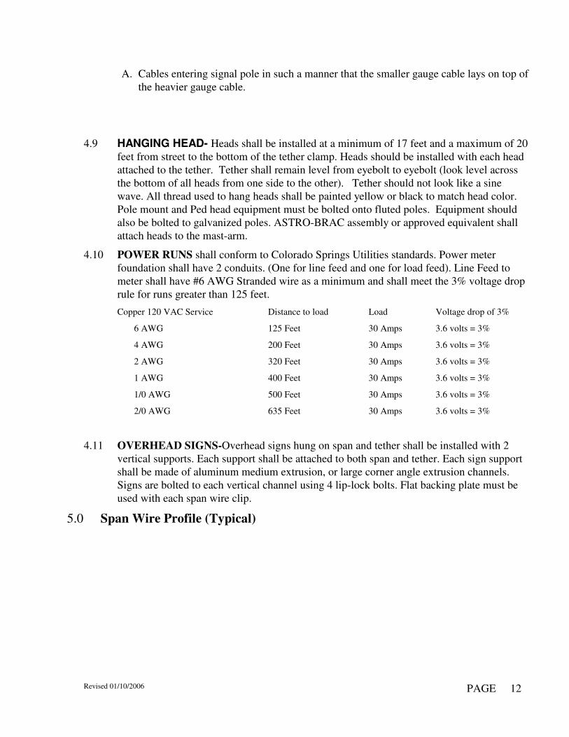
4.10 POWER RUNS shall conform to Colorado Springs Utilities standards. Power meter foundation shall have 2 conduits. (One for line feed and one for load feed). Line Feed to meter shall have #6 AWG Stranded wire as a minimum and shall meet the 3% voltage drop rule for runs greater than 125 feet.
Copper 120 VAC Service Distance to load Load Voltage drop of 3%
6 AWG 125 Feet 30 Amps 3.6 volts = 3%
4 AWG 200 Feet 30 Amps 3.6 volts = 3%
2 AWG 320 Feet 30 Amps 3.6 volts = 3%
1 AWG 400 Feet 30 Amps 3.6 volts = 3%
1/0 AWG 500 Feet 30 Amps 3.6 volts = 3%
2/0 AWG 635 Feet 30 Amps 3.6 volts = 3%
4.11 OVERHEAD SIGNS-Overhead signs hung on span and tether shall be installed with 2 vertical supports. Each support shall be attached to both span and tether. Each sign support shall be made of aluminum medium extrusion, or large corner angle extrusion channels. Signs are bolted to each vertical channel using 4 lip-lock bolts. Flat backing plate must be used with each span wire clip.
5.0 Span Wire Profile (Typical)

Revised 01/10/2006
�PAGE �13�
6.0 CABLE COLOR CODES AND USAGE
6.1 The purpose of this instruction is to develop and codify standard color-codes for signal cables and to develop a basis for selecting color codes for nonstandard applications.
6.2 All cable purchased by Traffic Engineering for signal use comes under the IMSA 19-1 1984 specification which sets insulation and performance standards as well as establishing a color sequence. The conductor base color is overlaid with a tracer giving a distinctive and unique color combination for each conductor. The six base colors are:
BLACK GREEN WHITE ORANGE RED BLUE
6.3 For a multiconductor cable these colors are repeated as necessary with an appropriate tracer color. The first twenty (20) conductors are:
1) BLACK 11) BLUE/BLACK 2) WHITE 12) BLACK/WHITE 3) RED 13) RED/WHITE 4) GREEN 14) GREEN/WHITE 5) ORANGE 15) BLUE/WHITE 6) BLUE 16) BLACK/RED 7) WHITE/BLACK 17) WHITE/RED 8) RED/BLACK 18) ORANGE/RED 9) GREEN/BLACK 19) BLUE/RED 10) ORANGE/BLACK 20) RED/GREEN
6.4 As the same colors are used for the tracers as for the base color, it is obvious that the tracer
color cannot be applied to its same color, which limits a given tracer color to less than six, but

Revised 01/10/2006
�PAGE �14�
the base colors do nonetheless repeat by groups of six. The IMSA specification also sets a required pattern for cable construction so that for all manufacturers, the cable will be at the center and Black/White will be adjacent to the Blue/Black. This can help locate a conductor if the tracers have been rubbed off. The manufacturer may choose to wrap primary base colors again. When this occurs, the primary base colors will be those closest to the inside wrap and the secondary colors will be those closest to the outside wrap. Secondary colors will be referred to as red 2nd, green 2nd, and black 2nd, etc.
6.5 Conductor colors are always in both written or spoken communications described with the base color first, and the tracer color next. IN print, the (/) is usually used to separate the colors. Verbally, the phrase “with a” is usually inserted to separate the colors. Abbreviated versions of the colors are often used for convenience, these are:
BLACK - BLK GREEN - GRN WHITE - WH YELLOW - YEL RED - RED BLUE - BLU
7.0 COLOR CODE: TRAFFIC SIGNAL WIRING
PHASE 25/C 19&20/C 12&15/C 2&6 RD RD RD RD AMB AMB AMB AMB GRN GRN GRN GRN DW RD/WH RD/WH RD/WH(15/C) W GRN/WH GRN/WH GRN/WH(15/C) 4&8 RD RD/BLK RD/BLK RD/BLK AMB AMB/BLK AMB/BLK AMB/BLK GRN GRN/BLK GRN/BLK GRN/BLK DW BLK/WH BLK/WH W BLU/WH BLU/WH 1&5 RD LT RD 2nd (RD/BLU) RD/GRN (20/C) AMB LT BLK BLK BLK GRN LT BLU BLU BLU 3&7 RD LT BLK/RD BLK/RD AMB LT AMB/RD AMB/RD BLK/WH GRN/LT BLU/RD BLU/RD BLU/BLK SPARES RD/GRN BLU/BLK BLU/WH(15C) AMB/GRN BLK 2ND (BLK/GRN) (Lighted Arterial Signs) GRN 2ND (GRN/AMB) BLU/BLK COMMON WH WH WH

Revised 01/10/2006
�PAGE �15�
WH 2ND WH/BLK WH/BLK WH/BLK WH/RD WH/RD
8.0 UNDERGROUND CONDUIT AND PULLBOX INSTALLATION INSTRUCTIONS.
8.1 Underground conduit shall be a minimum of 3 inches (inside diameter) and shall be C Schedule 80 Poly Vinyl Chloride (PVC) conduit. Conduit shall be buried not less than 24 inches, 30 inches for all power runs. Proper conduit fittings and PVC cement shall be used to connect conduit. Under no circumstances shall improvised fittings or taped together joints be made. Under no circumstances shall size of conduit be changed in a continuous run. Conduit shall be installed in a manner that shall not cause problems in the installation of wire or shall not cause hazards to conduit or cabling due to crush hazards or settling of soil.
8.2 Conduit crossing under paved streets, alleys or sidewalks shall always include no less than
two runs of conduit, and more runs shall be included if specified. Conduit runs crossing under streets shall be C Schedule 80 Poly Vinyl Chloride (PVC) conduit only Conduit runs
for mast arm intersections shall utilize 2-3” and 1-2” conduits minimum, (one 2” for StreetLights and two for Traffic Signals). All other underground conduit runs shall be run in pairs unless single conduit runs are specified. All conduits shall be continuous, free of dirt and debris, and ends of conduit shall be taped to prevent entrance of dirt and water and rodents.
8.3 Backfilling: All trenches must be backfilled in lifts. Each lift (approx. 8”) must be tamped
or compressed. All soil removed from trench shall be placed back in trench.
8.4 Bends in conduit shall be made by means of factory prepared radius bends and appropriate couplings. Bends made by heating and bending conduit shall not be allowed unless special
permission is granted. Additive total of bends (in degrees) shall under no circumstances
be more than 360 degrees between openings of conduit, including upturn bends at
pullboxes and bell ends shall be installed on each conduit in j-box.
Revised 01/10/2006
�PAGE �16�
8.5 Conduit entering steel poles shall enter pole base under ground level and thus into pole
using PVC conduit. Pole base may not be cut above ground level nor shall conduit cross concrete base.
8.6 Pullboxes shall be approximately (Plus or minus 1”) 27 inches long x 16 inches wide x 12
inches minimum depth. Pullboxes shall be 20K rated polymer rock fiber concrete or reinforced fiber (No PVC). Removable top shall be imprinted “TRAFFIC SIGNAL” and shall be secured by stainless steel bolt (1/2” x 13 NC pentahead bolt with washer). Must have easy clean out holes. Under no circumstances shall any underground conduit be terminated at anything but a pole riser or a pullbox. Pullboxes shall be installed so that the
pullbox cannot sink. A minimum depth of six inches of gravel shall be placed in the
bottom of each pullbox and extend out 6” from box on all sides.
8.7 Contractor shall provide and install pullboxes next to each pole base to receive the Traffic Signal conduits extending from the base and insert one ground rod per foundation.

Revised 01/10/2006
�PAGE �17�
UNDERGROUND CONDUIT AND PULLBOX INSTALLATION INSTRUCTIONS- (continued)
6"
6"
6"
6"
GRAVEL
CONCRETE CO
NCRETE
6"
10" 10"
TRAFFICSIGNALS
CONCRETE
COLLAR
Top View
8.8 Pull boxes shall have a concrete collar placed around them when used on Highway
projects and when Signals inspector determines a need. Pullbox shall be placed so that top of box is 1 inch above grade to prevent water from entering box, with the exception of pullboxes placed in a sidewalk which shall be at grade. Side of pullbox shall not be cut to allow entrance of conduit unless special permission is granted. All conduits entering pullboxes shall be equipped with a 90-degree bend placed so that wire can be pulled out of
the box without rubbing against the pullbox. Conduit bends shall be installed so that
open end of bend is between 6 and 8 inches to top of pullbox cover. Conduits shall
be within 3 inches of the side from which conduit enters the pullbox. Where rigid conduit enters pullbox, plastic bushings shall be provided at open end of bend. Rebuilding of underground conduit could involve special circumstances and permission is required from the Traffic Engineer or designee regarding deviations from standards.
8.9 Underground conduit runs shall have a pullbox installed every 300 feet maximum, or
centered in the run if over 300 feet long. Less than 300 feet requires a pullbox only at terminations.
8.10 All underground conduit runs shall have a single 14 AWG (min) THHN wire installed
from pullbox to pullbox for locating purposes. 8.11 All underground conduits shall have a single ¼ “ Nylon pull rope installed from pullbox
to pullbox with a minimum of 3’ of slack in each box.
8.12 Conduits shall terminate in J-boxes with bell ends installed on each conduit.

Revised 01/10/2006
�PAGE �18�
9.0 Illuminated Street Name Signs (Optional, may be required).
9.1 Sign should be 8’ x 18”. Frame will be aluminum alloy to match galvanized poles and should be powder coated black to match black poles. Sign can be 6’ x 18” for short street names.
9.2 Photocell shall be mounted on the side of the sign.
9.3 Sign panel on back of sign shall be blank. (unless ordered differently)
9.4 Lettering shall be 8” with Highway Gothic EM font. Numbers shall be 4”. White legend
and border on a Highway Green field.
9.5 Two fixed length swing sign brackets shall be used to install illuminated street name signs. (Hawkins M10J-OCB250FL(S)).
9.6 Illuminated sign will be attached to Sign Mount Arm with 2 fixed length swing arm brackets when used with span wire poles.

Revised 01/10/2006
�PAGE �19�
10.0Combination Lighting and Traffic Signal Standards
10.1GENERAL-Fluted poles shall consist of tapered pole, round, curved tapered traffic signal mast arm (if required), luminaries arm, hand hole covers, anchor bolts, washers / nuts for anchor bolts and base plate.
10.2CALCULATIONS- Calculations, if required, shall include mast arm, luminaries arm, pole, base plate, and anchor bolt analysis. Tube drag coefficients shall be increased to include the effects of fluted shapes. Maximum loads and stresses shall be determined for the most critical wind direction. The pole shall be analyzed in its final deflected position, at the arm to pole connection(s) and pole base. Maximum arm and pole loads, stresses and combined stress ratios (CSR) shall be provided for the specified loading combinations, as well as maximum top of pole dead load rotation. Shaft dimensions shall be equivalent in strength for the loads shown on the drawings.
10.3POLE-The 16 flute pole shall be formed from tubes conforming to ASTM A595 Grade A with a minimum yield strength of 55 ksi, and have a constant linear taper of 0.14 in/ft. The flutes shall terminate approximately 2” from the base plate connection to facilitate welding and for aesthetic appeal. The shaft shall be one piece, and contain no circumferential welded butt splices. Laminated tubes are not permitted. The pole shall have a reinforced 4.0" x 6.5" handhole with cover located 1'-6" from the pole base. Each pole shall be provided with a decorative end cap secured in place with setscrews. The pole shall be hot dip galvanized and powder coated as specified in the contract documents.
10.4MASTARM- The mast arms shall be round, curved and formed from tubes conforming to ASTM A595 Grade A with a minimum yield strength of 55 ksi, and have a constant linear taper of 0.14 in/ft. Mast arms up to 50’ in length shall be manufactured and shipped in one piece. Circumferential welded tube butt splices and laminated tubes are not permitted. Each arm shall be provided with an end cap secured in place with setscrews. The mast arm shall be hot dip galvanized and powder coated as specified in the contract documents.
10.5FLUTING PROCESS-The pole shall be cold rolled over a precision hardened steel mandrel to form a 16-flute shaft. The fluted shaft shall have uniform, equally spaced flutes. The flutes shall be formed with rollers in full contact with the material from the top of the crest, through the valley of the flute, to the top of the next crest. Individually rolled flutes or round poles with a separate fluted sheathing are not permitted.
10.6BASE PLATE-Base plates shall conform to ASTM A36. Plates shall be integrally welded to the tubes with a telescopic welded joint, and is hot dip galvanized and powder coated as specified in the contract documents.

Revised 01/10/2006
�PAGE �20�
10.7ANCHOR BOLTS- Anchor bolts shall conform to the requirements of AASHTO M314 Grade 55. The upper 12" of the bolts shall be hot dip galvanized per ASTM A153. Each anchor bolt shall be supplied with two hex nuts and two flat washers. The strength of the nuts shall equal or exceed the proof load of the bolts. A decorative cast aluminum nut cover shall be provided for each anchor bolt. Each nut cover shall be attached to the pole with a 0.25” stainless steel, self-tapping, hex head screw.
10.8 DESIGN-Design shall be in accordance with the 1994 AASHTO "Standard Specifications for Structural Supports for Highway Signs, Luminaries and Traffic Signals." Loading shall be based on wind velocity of 90 mph times a 1.3 gust factor. Calculations and detailed drawings shall be submitted demonstrating compliance with the AASHTO specification.
10.9FABRICATOR- The Fabricator shall be certified under Category I, "Conventional Steel Structures" as set forth by the American Institute of Steel Construction Quality Certification Program. Proof of this certification will be required prior to bid opening to ensure that the fabricator has the personnel, organization, experience, procedures, knowledge, equipment, capability and commitment to fabricate quality Traffic Pole Structures.
10.10 WELDING-All welding shall be in accordance with Sections 1 through 8 of the American Welding Society (AWS) D1.1 Structural Welding Code. Tackers and welders shall be qualified in accordance with the code. Tube longitudinal seam welds shall be free of cracks and excessive undercut, performed with automatic processes, and be visually inspected. Longitudinal welds suspected to contain defects shall be magnetic particle inspected. All circumferential butt-welded pole and arm splices shall be ultrasonically and radiographically inspected.
10.11 MATERIAL CERTIFICATIONS-All materials and products shall be manufactured in the United States of America, and comply with ASTM or AASHTO specifications. Mill certifications shall be supplied as proof of compliance with the specifications.
10.12 COMBINATION COATING GALVANIZED-POWDER TOP COAT- (Surface Preparation)-Prior to being incorporated into an assembled product, steel plates ¾ inches or more in thickness shall be blast cleaned when required to remove rolled-in mill scale, impurities and non-metallic foreign materials. After assembly, all weld flux shall be mechanically removed. The iron or steel product shall be degreased by immersion in an agitated 4.5%-6% concentrated caustic solution elevated to a temperature ranging from 150 to 190 degrees Fahrenheit. It shall then be pickled by immersion in a heated sulfuric acid solution of 6%-13% concentration, with a controlled temperature between 150-190 degrees Fahrenheit. It shall next be rinsed clean from any residual effects of the caustic or acid solutions by immersion in a circulating fresh water bath. Final preparation shall be accomplished by immersion in a concentrated zinc ammonium chloride flux solution heated to 130 degrees Fahrenheit. The solution’s acidity content shall be maintained between 4.5-5.0 pH. The assembly shall be air dried to remove any moisture remaining in the flux coat and/or trapped within the product.

Revised 01/10/2006
�PAGE �21�
10.13 ZINC COATING-The product shall be hot-dip galvanized to the requirements of either ASTM A123 (fabricated products) or ASTM A153 (hardware items) by immersion in a molten bath of prime western grade zinc maintained between 810-850 degrees Fahrenheit. The entire product shall be totally immersed with no part of it protruding out of the zinc (no double dipping). This it to limit a risk of trapped contaminates containing chlorides and reduce the risk of bare spots (bare spots can occur when flux on the steel surface is burned away by heat of the first dip). Maximum aluminum content of the bath shall be 0.01%. Flux ash shall be skimmed from the bath surface prior to immersion and extraction of the product to assure a debris free zinc coating.
10.14 EXTERIOR CAOTING-All galvanized exterior surfaces shall be coated with a Urethane or Triglycidyl Isocyanurate (TGIC) Polyester Powder to a minimum film thickness of 2.0 mils (0.002”). Prior to application, the surfaces to be powder coated shall be mechanically etched by brush blasting (Ref. SSPC-SP7) and the zinc coated substrate preheated to 450 degrees for a minimum of one hour in a gas fired convection oven. The coating shall be electrostatically applied and cured in a gas fired convection oven by heating the zinc coated substrate to a minimum of 350 degrees Fahrenheit and a maximum of 400 degrees Fahrenheit. The thermosetting powder resin shall provide both intercoat as well as substrate fusion adhesion that meets 5A or 5B classifications of ASTM D3359.
10.15 POWDER COATING-Poles shall be powder coated over galvanizing Semi Gloss
Black/ Polyester TGIC or equivalent.
10.16 PACKAGING-Prior to shipment small poles shall be wrapped in 0.188” thick Ultraviolet-inhibiting plastic backed foam. Larger poles shall be cradled in a 1.0” rubberized foam base.
10.17 Delivery of Mastarms/Poles-The Bidder shall advise the City of delivery date and time, one (1) week prior to delivery. This is to assure that equipment is available for unloading. Failure to do so will result in delay in off loading. NO DELIVERIES WILL BE ACCEPTED ON MONDAY, FRIDAY, WEEKENDS AND HOLIDAYS.
10.18 Penalty-Material must be delivered within 18 weeks after the date of purchase order or
a $50.00 a day penalty will be assessed.

Revised 01/10/2006
�PAGE �22�
11.0 Traffic Signal Standards and Pole Data. (Valmont pole this page)

Revised 01/10/2006
�PAGE �23�
11.1 POLE DATA
TABLE 3: (Valmont)
16 FLUTE POLES (CS-SW- (60-150))
Span Pole Data Pole Base Data Anchor Bolt Data *
Signal Span (Ft)
Base DIA. (IN)
Top DIA. (IN)
Length
(FT) Gauge Or Thick (IN)
Square “S” (IN)
Bolt Circle “Y” (IN)
Thick “M” (IN)
DIA. “K” (IN)
Length “J” (IN)
Hook “H” (IN)
Thread Length “U” (IN)
Small 13.50 9.02 32.00 .250 17.00 16.00 2.00 1.75 84.00 6.00 10.00
Up to 150’
16.00 11.52 32.00 .250 23.00 22.00 2.00 2.00 84.00 6.00 10.00
TABLE 3A: (Union Metal)
16 FLUTE POLES
Pole Data Span Pole Base Data Anchor Bolt Data #
Design number
Gauge or Thick (IN) Base DIA. (IN) Top DIA. (IN)
Length (FT)
Signal Span (Ft)
Square “S” (IN)
Bolt Circle “Y” (IN)
Thick “M” (IN)
DIA. “K” (IN)
Length “J” (IN)
Hook “H” (IN)
Thread Length “U” (IN)
T50055 Y4
F3--11.50--7.02--32.00 Up to 120’
17.00 16.00 1.75 1.75 90.00 6.00 8.00
T50055 Y5
F3--15.00--10.52--32.00
121’ to
150’
23.00 22.00 2.00 2.00 90.00 7.00 12.00
T50055 Y6
F3--17.00--12.52--32.00
151’ to
175’
25.00 24.00 2.00 2.00 90.00 7.00 12.00
All Poles ordered shall include hand hole covers, luminaire arm,.anchor bolt, nuts & washers.

Revised 01/10/2006
�PAGE �24�
11.2 Typical pole and mast arm (With Decorative Globe)
Used for the downtown only. Color is (Federal Green RAL 6004 with Corothane) Sherwin Williams should be able to match this. . 250W HPS, 120V, Dark Green Housing, Optical Type III, Spike Finial, Bands & Ribs, Button Style Photocontrol. An example order would look like: WA-250HPS-12-N-3-Z-6-PR.
Cast aluminum split pedestal baseW/(2) access doors @ 180*(optional)
15'
5'
pressed stl. end capw/ stn. stl. screw
2'-1 1/2" DIA.
3" X 5" Handholeopposite armw/ cover & J-hook
cast aluminum finial
Washington Postlite Luminaires withfinial, ribs, band and medallions
Removable ballast assembly
(2) sets (3) eachs/s 1/4"-20 set screws
3 1/2" O.D.tenon welded to tube

Revised 01/10/2006
�PAGE �25�
11.3 Typical Pole and Mast arm With Luminaries (Union Metal)
ANCHOR BOLTHOLE
arm spread per design chart (.14" taper/ft
.
16 Flute tape
red stl m
onotub
e 32'-0"
(.14 in/ft taper)
.15'-0" NOM
(4.6m)
60'-o" RAD(18.3m)(except 44' RAD on 25' arm)(13.4m)
3" x 5" HandholeOpposite arm w/cover & J-hook
Round steel monotube
Pressed steel endcap w/stn stl screw
42"
(1067)
Cast alum pole topw/ J-hook weldedinside pole 11GA round arm
(3.0)
(11.67 mm/m)
Field Joints Forarms over 40 Ft.
18" (45')(457)
21" (50' & 55')(555)
Telescopic Joint
(1.5m) 5'-0" Nominal RiseArm Plate to tangent @ arm (with loads applied)
1/2" Dia galv stud with (2)"ANCO" locknuts, 3/4" DiaHole factory drilled in outboardtube, field drill inboard tubeto assume snug fit.
5'
.
6"(152
)
STRUCTURE FINISH:FINISH COAT; TCIG OR URETHANE POLYESTER POWDER.COLOR - SEMI GLOSS BLACK
DESIGN CRIERIA:1994 AASHTO "STANDARD SPECIFICATIONS FOR STRUCTURALSUPPORT FOR HIGHWAY SIGNS, LUMINAIRES AND TRAFFICSIGNALS.90MPH WIND ZONE TO SUPPORT CUSTOMER LOADING.
4" X 8" CURVED HANDHOLE FRAMEW / 1/2"-13 GRD. LUG & COVER@ 0° ON ALL DESIGNSORIENT AWAY FROM TRAFFIC FLOW
FOUNDATION SURFACEMUST BE LEVEL
NOTE:1). THE EXPOSED LENGTH OF THEANCHOR BOLT BETWEEN THE TOP OFTHE FOUNDATION AND THE BOTTOM OFTHE LEVELING NUT SHOULD NOTEXCEED ONE BOLT DIAMETER.
40 1/2" (#230)
(1028.7)
41 7/8" (#260)
(1063.7)
11 1/2" (#230)
(292.1)
14" (#260)
(355.6)(638.2)
25 1/8" (# 230)
31 1/4" (# 260)
(793.8)
MATERIAL SPECIFICATIONSTUBES: CHEM. & PHYSICAL PROP. OF ASTM A595 GR. A.PLATE.BAR: ASTM A36ANCHOR BOLTS: ASTM F1554 GR. 55NUTS: (INC ANCHOR) ASTM 563 GR. A.MISC. HOWE: (STN. STL) AISI 300 SERIES (18-8)ALUMINUM CASTINGS: AA319.OF
(Optional)
Optional--Nut Covers
12' or 20'

Revised 01/10/2006
�PAGE �26�
11.4 POLE and MAST-ARM SCHEDULE (Union Metal)
Design # Arm Length Arm Size Pole Size Foundation Size
T50608-Y12 25’-0” (7.6m)
3E - 7.00 x 3.40 x 25’-9” (6.4E-178 x 85 x 7.8m)
30” x 10’
T50608-Y13 30’-0” (9.1m)
3E – 8.00 x 3.70 x 30’-9” (6.4E –203 x 94 x 9.4m)
3F – 11.50 x 7.02 x 32’
(6.4F – 292 x 178 x 9.8m)
16” B.C. 30” x 10’
T50608-Y14 35’-0” (10.7m)
3E – 9.00 x 4.00 x 35’-9” (6.4E – 229 x 102 x 10.9m)
3’ x 10’ (1m x 3m)
T50608-Y15 40’-0” (12.2m)
3E – 9.50 x 3.80 x 40’-9” (6.4E – 241 x 97 x 12.4m)
3F – 13.00 x 8.52 x 32’-0”
(6.4F – 330 x 216 x 9.8m)
22” B.C. 3’ x 10’
(1m x 3m)
T50608-Y16
45’-0”
(13.7m)
3E – 10.00 x 6.01 x 28’-6” (6.4E – 254 x 153 x 8.7m) 7E – 6.62 x 4.00 x 18’-9” (4.6E – 168 x 102 x 5.7m)
3’ x 10’
(1m x 3m)
T50608-Y17 50’-0”
(15.2m)
3E – 11.50 x 7.09 x 31’-6” (6.4E – 292 x 180 x 9.6m) 7E – 7.70 x 4.80 x 20’-9” (4.6E – 196 x 122 x 6.3m)
3’ x 10’
(1m x 3m)
T50608-Y18 55’-0”
(16.8m)
3E – 11.50 x 7.09 x 32’-0” (6.4E – 292 x 180 x 9.6m) 7E – 7.70 x 4.10 x 25’-9” (4.6E – 196 x 104 x 7.6m)
3’ x 12’
(1m x 3.7m)
T50608-Y33 60’-0”
(18.3m)
3E – 11.50 x 7.09 x 32’-0” (6.4E – 292 x 180 x 9.6m) 7E – 7.70 x 3.40 x 30’-9” (4.6E – 196 x 86 x 9.4m)
3F– 15.50 x 11.02 x 32’-0”
(6.4F – 394 x 281 x 9.8m)
22” B.C.
3’ x 12’
(1m x 3.7m)
T50608-Y 65’-0”
(19.8m)
3E-12.50 x 6.90 x 40’-0” [6.4E – 318 x 175 x 12.2m] 7E – 7.54 x 3.69 x 27’-6” [4.6E – 192 x 94 x 8.4m]
3’ x 18’ (1m x 4.9m)
T50608-Y 70’-0” (21.3m)
E – 13.50 x 8.32 x 37’-0” [6.4E –343 x 211 x 11.3m] 7F – 8.96 x 3.99 x 35’ 6” [4.6E – 228 x 101 x 10.8m]
3F-17.00” x 12.52" x 32’-0” [6.4F – 394 x 280 x 9.8m]
22 ½ “ B.C. 3’ x 18’
(1m x 4.9m)

c:\data\misc\tsspecs.doc � DATE �10/27/2009�
�PAGE �27�
11.5 POLE and MAST-ARM SCHEDULE (Valmont)
Pole Data Base Plate Data Anchor Bolt Data Mast Arm Data
Base DIA (in)
Top DIA (in)
Length (ft)
Gauge or THK
square “S”
(in)
Bolt Circle “Y”
(in)
THK “M”
(in)
DIA “K” (in)
Length “J”
(in)
Hook
“H” (in)
thread length
“U” (in)
Fixed End Dia (in)
Free End Dia (in)
Gauge Span (Ft)
Rise (Ft)
Attach -ment Height
(Ft)
12.5” 8.02 32.00 5 17” 16” 1.50 1.50 54.00 6.00 8.00 8.00 4.42 7 25’ 3’ 17’
12.5” 8.02 32.00 5 17” 16” 1.50 1.50 54.00 6.00 8.00 9.00 4.73 7 30’ 3’ 17’
13.0” 8.52 32.00 3 23” 22” 1.75 2.00 84.00 6.00 10.00 10.00 5.02 7 35’ 4’ 16’
13.0” 8.52 32.00 3 23” 22” 1.75 2.00 84.00 6.00 10.00 11.00 5.30 7 40’ 4’ 16’
15.5” 11.02 32.00 0.250 23” 22” 1.75 2.00 84.00 6.00 10.00 11.50 5.10 7 45’ 4’ 16’
15.5” 11.02 32.00 0.250 23” 22” 1.75 2.00 84.00 6.00 10.00 12.00 4.96 7. 50’ 4’ 16’
15.5” 11.02 32.00 0.250 23” 22” 1.75 2.00 84.00 6.00 10.00 13.00 5.59 Det.5 55’ 5’ 15’
15.5” 11.02 32.00 0.250 23” 22” 1.75 2.00 84.00 6.00 10.00 12.50 4.40 Det.5 60’ 5’ 15’
16.5” 12.02 32.00 0.250 23” 22” 1.75 2.00 84.00 6.00 10.00 14.12 5.50 Det.5 65’ 0 20’
17.5” 13.02 32.00 0.250 24” 23” 1.75 2.00 84.00 6.00 10.00 14.82 5.50 Det.5 70’ 0 20’

c:\data\misc\tsspecs.doc � DATE �10/27/2009�
�PAGE �28�
11.6 POLE and MAST ARM DETAILS (VALMONT)

c:\data\misc\tsspecs.doc � DATE �10/27/2009�
�PAGE �29�
12.0 LOADING INFORMATION (MAST-ARM)

c:\data\misc\tsspecs.doc � DATE �10/27/2009�
�PAGE �30�
12.1 LOADING INFORMATION (SPANWIRE)

c:\data\misc\tsspecs.doc � DATE �10/27/2009�
�PAGE �31�
13.0 TRAFFIC SIGNAL FOUNDATIONS
13.1 Foundation General notes:
13.2 Concrete = class B. Reinforced steal per AASHTO M31 specification, grade 420 for #29M, #16M, & #13M bars.
13.3 Shaft for concrete foundation to be drilled by mechanical auger.
13.4 Foundation design requires that the shaft be founded in compact sand, clay, or sandy clay. If
by visual inspection of the hole other material is present, the foundation design shall be modified as determined by the engineer.
13.5 Concrete shall be poured in lifts not exceeding 1m in depth. At the pouring of each lift,
concrete shall be mechanically vibrated to remove air pockets.
13.6 Foundation should be poured 7 to 10 days in advance of pole installation.
13.7 When ambient temperature is below (40*F) poured foundations shall be covered with blankets and /or straw per direction of the Engineer.
13.8 Concrtet poured at a depth greater than 14’ shall use a chute to pour.
13.9 All anchor bolts shall be ASTM F1554 Grade 55.
13.10 Foundation depths vary with the length of mast arms used. Basically, (up to 30 foot arm is
30” X 10’, 36” is ok), (35’to 50’ arm is 36” X 10’), (55’ to 60’ arm is 36” X 12’) and (65’ to 70’ arm is 36” X 18’). Span wire pole foundations will be 36” X 10’ until the distance between poles is greater than 120’. When greater than 120’ increase foundations to 36” X 14’. Some of the streets requireing 14’ minimum depth would be Academy Blvd, Powers, Garden of the Gods, Union, Research and Austin Bluffs.
13.11 Pole foundation may increase in depth and/or diameter as determined by Engineer. Project
Engineer may modify foundation design due to unforeseen conditions.
13.12 Contractor shall provide and install j-boxes and one ground rod at each foundation.

c:\data\misc\tsspecs.doc � DATE �10/27/2009�
�PAGE �32�
13.12 Foundation Typical Overview
#5 Stirrups
#8 Vertical bars
36" SQ. Formed base
22" Bolt circle
(bolt cicle may vary)
Typical conduit runs
Conduit risers
must be centered
Figure 1-2Figure 1-3
(Optional)
At Traffic Engineering requestRound Base Top (top view)
Traffic
Lights
Street
Signals2 - 3" Stubouts
#4 Hoops
one 2" Stubout
NOTES
1. Bolt positions shall be accurate to +/- 1/8”. Bolts shall be accurately square with curb line.
2. Conduit directions to be determined by traffic engineer or field representative.
3. Mark all conduit runs on top of concrete base. Marks should be 2” from perimeter of base.
4. Base dimensions may vary from standard due to engineering.
5. Base surface shall be smoothly finished with steel trowel and have a light broom finish.
6. Bolt circle may vary. (22” is standard).
7. Contractor shall provide and install J-boxes to receive conduits from each foundation.
8. Contractor shall provide and install one ground rod in signal j-box per foundation .
9. Install bell ends on each conduit.

c:\data\misc\tsspecs.doc � DATE �10/27/2009�
�PAGE �33�
13.13 TRAFFIC SIGNAL FOUNDATION (TYPICAL)
8"
3'
2'
36" DIA
6-#5 Stirrups at 12"=/-around anchor bolts.
nuts and washers.
Ground level
Undisturbed soil
11-#4 Hoo
ps @
11"-((3 0
" ) Dia. Ho op s)
9-#8 Vertical Bars
36" Base2" X 90" (Confirm Size)
1. Prior to pouring concrete, conduits shall be taped andanchor bolt threads shall be oiled.
3" PVC Longmedium sweeps
Top View
Base depth may be extended by T.E. due tosoil conditions or close proximity of trenches.
(ground)
SignalsJ-Box
2. Base shall be State Class B concret, Mix# 640821poured against virgin soil (undisterbed).
3. Concrete shall be vibrated.
4. Must maintain 3" minimum of concrete betweensides of hole and the steel cage.
8. Base surface shall be smooth finished withsteel trowel and have a light broom finish.
5. All conduit stubs shall extend freely 12" beyondthe pour and be fitted with a coupling on eachstub. Stubs shall be taped to prevent entry of dirtor concrete.
6. Loose dirt shall be removed from the bottom of thehole prior to pouring concrete.
7. Trash shall NOT be thrown into the hole.
9. Base top shall be flush to sidewalk grade orIf not attached to sidewalk, 1" above grade.
5"
10'
10. For mast arm lenghts 50' to 70' add to the depthof the foundation and increase reinforcing accordingly.
22" BoltCircle
anchor bolts W/Hex
J-Box
Stree
t lights
Bell Ends
8"
(Pole foundation may increase in depth and/or diameter as determined by Engineer). Project
Engineer may modify foundation design due to unforeseen conditions
Contractor shall provide and install conduit and J-boxes with each foundation.

c:\data\misc\tsspecs.doc � DATE �10/27/2009�
�PAGE �34�
14.0 TRAFFIC SIGNAL PEDESTAL (Aluminum for galvanized intersections and
Powder Coated Gloss Black when used with a black colored intersection)
14.1 Pedestal poles shall be designed to meet AASHTO 90 MPH wind velocity. Twelve feet threaded square base pedestal; to include pole, base and anchor bolts. Pole shall be aluminum 4.5 inches in diameter and twelve feet high with one end threaded for base. Base shall be cast aluminum with a 6-3/8 inch mounting radius, 15 inches high, threaded to receive 4.5-inch aluminum pole. Threads shall be 4” NPSM. Anchor bolts shall include nuts and washers, be ¾ inches in diameter, 18 inches in length and shall have an “L” bend
at the bottom. All hardware shall be bolted to the pole. Bottom of ped-head shall be mounted at 8’ above the sidewalk.
14.2 Foundations for pedestrian push button poles are the same except for the depth, which will be 24”.

c:\data\misc\tsspecs.doc � DATE �10/27/2009�
�PAGE �35�
15.0 TRAFFIC SIGNAL SCHOOL FLASHER
Pole and pole base shall be made of steel and black powder coated Semi-Gloss Black during fabrication. Pole shall be 4.5 inches in diameter, 15’ high and one end threaded for base. Threads shall be 4” NPSM. In the event poor soil conditions exist, base may be increased to 5’ in depth. Unit shall have 3 flashing indications. 2 indications shall face motorists as they approach school zone and wig-
wag. All hardware shall be bolted to pole
7'
8' Ground Rod
3/4" Agragate
Junction Box
Control Box
5'
Battery
SPEED
LIMIT
20WHEN
FLASHING
FINES DOUBLED
IN SCHOOL ZONES
SCHOOL
15'
3-#3hoops
4-#4vertical bars
Pole and base shall be black powder coatedSemi Gloss Black or equivalentAll hardware shall be black in color.
5'
6'
OptionalSteelScrew-inFoundation13" BC
16.0 SCHOOL FLASHER FOUNDATION
Prior to pouring base:
• Tape conduit ends and oil bolt threads.
• Concrete shall be vibrated.
• Base surface shall be smooth finished with steel trowel and have a light broom finish.
• Mark conduit runs on top surface of base.

c:\data\misc\tsspecs.doc � DATE �10/27/2009�
�PAGE �36�
FLASHER FOUNDATION
17.0 Power Meter Pedestal Specifications
17.1 All non-current carrying metallic parts to be bonded to neutral and effectively grounded. Color to be standard gray or power coated gloss black when required. (Intersection – 1PH-
120/240V 3Wire) METER SHALL BE RINGLESS PER CSU.
Procedure for power to an intersection: 1) Contact CSU electrical field engineer of the area to make sure of power source in the area. South District-668-5564, North District-668-4985 2) Obtain address from Regional Building, Flood Plain Division. 3) Fill out Load Data sheet and fax or mail to the proper CSU district, north or south. 4) Obtain permit from Regional Building-to be done by contractor. 5) Call in for inspections: Done by contractor.
6) Regional will contact CSU, so that they can inspect the installation. To find out the status of the power, you can call 668-5524 with the address.
7) .

c:\data\misc\tsspecs.doc � DATE �10/27/2009�
�PAGE �37�
The process from the time the inspection is called in to Regional, should take 10 to 12 working days.

c:\data\misc\tsspecs.doc � DATE �10/27/2009�
�PAGE �38�
18.0 SPECIFICATIONS FOR WIRE
18.1 PPB-Paired Cable shall comply with IMSA specification 19-1. Cable shall be minimum 6
conductors of 18 AWG. Cable shall be black PVC jacketed (.030 inches) overall with polyethylene insulation. Cable shall be shipped on sturdy wooden spools of 1,000 non-interrupted feet. Cable shall be equipped with a ripcord.
18.2 Signal Cables; shall comply with IMSA specification 19-1. Conductors are to be 14 AWG, comprised of no less than 7 strands and will be untinned. Conductor insulation shall be polyethylene. The cable jacket shall be of polyvinyl chloride only, and may not be unduly rigid. Tracer colors shall be painted onto the wire insulation but must be unremovable and a
spiral design is preferred. Cable shall be shipped 1,000 non-interrupted feet on spools. Spools shall be sturdy and constructed of wood. Spools shall be non-returnable. Cable shall be equipped with a ripcord.
18.3 Camera Cable/ Camera Power Cable: Composite, 6 conductors-2 elements; 16 AWG 5-conductors bare stranded copper (conductor colors shall be black, white, blue, red and brown), .016 polyethylene, 1 element equivalent to Belden 8281 with .030” PVC Jacket Black. This cable shall be suitable for installation in underground conduits or overhead with span wire applications. The coaxial cable, BNC connector and crimping tool shall be approved by Colorado Springs Traffic Engineering representative. Cable should be supplied
on sturdy wooded reels in lengths of 1000’ minimum. Any video cable not supplied by
City of Colorado Springs must be pre-approved before installation.
18.4 Aerial Telephone Drop Wire: 18.5 AWG parallel. Cat.No. ADR 182-PVC. (18.5 / 01P
SOL CCS Aerial). Cable shall be shipped 1,000 non-interrupted feet in pull-pac. (or equivalent).
18.5 Power Cable; From source to meter pedistal shall be a minimum #6 AWG THHN Stranded conductor. From Meter to cabinet PDA use #8 AWG THHN minimum.
18.6 Streetlight wire; #8 USE minimum for street lighting. For the wire in the pole from Cobra head to pole hand hole shall be #14-2/C min. All overhead splices shall be made in the hand hole at the base of the pole.

c:\data\misc\tsspecs.doc � DATE �10/27/2009�
�PAGE �39�
19.0 GALVANIZED STEEL CABLE
19.1 Cable is to be comprised of seven (7) strands of galvanized steel wire of gauge required to bring outside nominal diameter to specifications. Galvanizing must be class “A” (.9 oz. zinc per square foot) and each wire must be individually galvanized prior to cable assembly. Steel cable is to be Siemans-Martin Grade and minimum breaking strengths are to be:
3/16” 2,200 pounds 1/2” 12,100 pounds
19.2 Cable is to meet ASTM A475 Specifications. Cable shall be shipped on sturdy, non-returnable spools of 1,000 feet each; coils of wire not on spools shall be unacceptable.
20.0 TRAFFIC SIGNALS ACCESSORIES-
20.1 CONDUIT RUNNING THREAD-1 ½” x 3’ Galvanized steel conduit running thread (NPSM) used to space between top of signal head and ½” span wire. Finished product will be painted the same color as V-heads.
20.2 STRAND VISES-1/2” with long bale (Reliable #5254). To be used for ½”, 7 strand galvanized steel cable.
20.3 3/16” with long bale (Reliable #5249). To be used for 3/16”, 7 strand galvanized steel cable.
20.4 NOTE: Strand Vises to be attached to pole using 5/8 x 10” to 14” eye bolts two (2) each strand vises in each bolt eye. Thimble eye-bolt
21.0 CONDUIT OUTLET BODIES & ACCESSORIES
21.1 STANDARD MATERIALS- Mark 9 - Copper Free Aluminum, 3” Sand-Cast.
21.2 STANDARD FINISHES-Mark 9 - Aluminum Cellulose Lacquer
21.3 BLANK COVERS-To be sheet steel for Mark 9 conduit outlet bodies.
21.4 GASKETS-Neoprene
21.5 SERVICE ENTRANCE FITTINGS (WEATHER HEADS-Fittings shall have a clamp type cap to fit rigid conduit of specified sizes. Preferably hot dip galvanized.

c:\data\misc\tsspecs.doc � DATE �10/27/2009�
�PAGE �40�
22.0 TRAFFIC SIGNAL HEADS – VEHICLE 22.1 The housing shall be aluminum alloy and shall be of sectional construction to permit the
installation of additional sections for future needs. The tops and bottoms of signal sections shall be flat for interchangeability and have a 2-inch diameter hole in them.
22.2 The door shall be die cast aluminum alloy, which shall be hinged at the left side with a
substantial screw type fastener of stainless steel at the right side. The visor shall be of aluminum.
22.3 The door shall be gasketed to exclude dust and moisture.
22.4 Back of the signal head housing, outside of visor, backplates and doors, shall be powder
coated gloss black.
22.5 All gaskets shall be neoprene.
22.6 All signals shall have the terminal blocks in bottom half of red section with one common neutral.
22.7 All new installations will have backplates on each 3-section signal head.
22.8 All signals to be packaged one (1) per carton.
22.9 Traffic signal heads shall conform to the Manual on Uniform Traffic Control Devices.
22.10 Visors shall be tunnel type, open at bottom.
22.11 12” visors shall be 9 to 10 inches in length.
23.0 All Vehicle Signal Indications Shall Be LED Hi-Flux Expanded View. (LEDS shall be City of Colorado Springs approved)
23.1 All bidders are requested to read all specifications carefully and submit in writing any
exception they may have at least one week prior to the bid opening.
23.2 All LED’s shall be delivered to the City of Colorado Springs, Traffic Engineer, 420 West Fontanero, Colorado Springs, CO 80907. The City will take delivery in batches over a period of 12 months. Each batch will be delivered within 30 days from the date of the order or be subject to a $50.00 a day penalty.
23.3 Bidders may bid on any or all items. The City may award orders based on individual items,
categories, or total bid as is most advantageous to the City.
23.4 The City retains the right to reject any and all bids.
23.5 All material shall be F.O.B. City of Colorado Springs, Traffic Engineer, 402 West Fontanero, Colorado Springs, CO 80907.

c:\data\misc\tsspecs.doc � DATE �10/27/2009�
�PAGE �41�
23.6 LED Vehicle SIGNAL INDICATIONS: All signal indications shall be HI-FLUX Expanded
view. (All indications shall not show any strings of LEDS). Profile type Shall be full, not outlining for arrows.
23.7 TRAFFIC SIGNAL HEADS “LED”-LED Traffic Signal Section optical units shall meet or exceed ITE Adjustable Face Vehicular Traffic Control and Pedestrian Signal Head Standards. In addition to this, LED optical units shall conform to the following requirements:
23.8 Minimum number of LED’s per Optical Unit: The minimum number of LEDs per optical unit shall be as specified by the manufacturer to meet ITE luminance specifications for signal installation.
23.9 Circuit Configuration: The LEDs shall be connected to form multiple series circuits. All series circuits shall be interconnected at intervals, forming subcircuits not exceeding 15 LEDs for red ball and arrow signals, and 10 LEDs for the pedestrian hand symbol. In the event of an LED failure, these subcircuits shall limit the number of extinguished LEDs to no more than 2% of the total on the ball and pedestrian hand signal lamps, and 6% of the total on the red arrow lamp.
23.10 Enclosure; Shall be dust and water-resistant.
23.11 Voltage; Operating shall be between 80VAC and 135 VAC. Electronic circuitry shall assure proper operation of the load switch and monitor in the cabinet.
23.12 Wattage: � Max. 25 watts for 12” (300 mm) Ball. � Max. 15 watts for 12” (300 mm) arrow. � Maximum total harmonics current distortion (THD) shall be < 20%. � Power factor shall be >90%. � Load balance requirement: load in one phase shall not exceed the load in any other phase
by 15%.
23.13 Operating Temperature; Between –40 degrees C and +74 degrees C.
23.14 Note; THD and power factor requirements shall be waived for products designed to operate at less than 14 watts.

c:\data\misc\tsspecs.doc � DATE �10/27/2009�
�PAGE �42�
23.15 Lens: Shall be replaceable, polycarbonate (UV stabilized “Lexan”) convex lens; meet ITE color standards; minimum of 1/8 “ thickness; and minimum light transmittance of 92%, free from bubbles, flaws and other imperfections. Non-polycarbonate red tinted lenses will be accepted provided that these meet ITE color standards. Chromacity shall be measured uniform across the face of the lens. Non-polycarbonate lenses shall also meet 3-1/2 foot tests.
23.16 Candlepower Distribution; Shall meet minimum ITE specifications. Intensity shall be measured uniform across the face of the lens. Brightness shall be maintained in the event of a voltage fluctuation or voltage drop.
23.17 Beam Spread; 30 degrees to each side.
23.18 Warranty: The City requires a 5-year warranty on all traffic signal led’s. This warranty excludes acts of God or vandalism.
24.0 Break-away tether assembly
24.1 Consists of cast aluminum threaded assembly to fit bottom of signal head. Assembly unit shall have single stud for tightening.

c:\data\misc\tsspecs.doc � DATE �10/27/2009�
�PAGE �43�
25.0 ENTRANCE FITTING/SIGNAL HEAD HANGERS
25.1 Entrance fitting is a casting that couples to signal head to lower end and has a drilled rib at top to connect to cable suspension clamp. Rib is to have a series of holes beginning at centerline of signal head connector to allow for correct positioning of off-balance signal head assemblies. Pinholes are to be designed for 5/8” pin. Rib shall not be more than .625 in thickness. Integral path for wire shall be free of sharp edges and constrictions and shall have a plastic bushing at its head. Threads in entrance fitting shall also be 1 ½” NPSM. Fitting shall have 5/16” NC set screw inside to prevent chase nipple loosening. Bottom of entrance fitting shall either bear serration’s for standard 72 position signal grip or shall be equipped
with locking washer bearing standard 72 position signal grip. Shurlock rings shall be
constructed out of metal or aluminum. Plastic shurlock rings shall not be used. Chase nipple shall be grooved and shall include O-Ring to seal signal head. Both entrance fitting
and chase nipple shall be malleable iron and shall be painted gloss black.
26.0SPECIFICATIONS FOR SUSPENSION CLAMPS
26.1 Suspension clamps must be at least 7 inches long and is to be of malleable iron. Clamp and pin shall be galvanized (Class “A”, .9 oz. zinc per square foot). Hole drilled in tangs for pin shall be 5/8” and 5/8” pin shall be supplied. Width between tangs shall be .70” +/- .025”. Clamp bolts may be “J” bolts with two (2) nuts although “U” bolts with four (4) nuts are preferred. “J” or “U” bolts, nuts, and lock washers shall be cadium plated. 5/8” pin shall be drilled for minimum 1/8” diameter cotter pin, which shall be, supplied cadium plated. Minimum ultimate strength shall be 16,000 pounds. Clamp is to be usable on either 3/8” or ½” stranded steel cable.b Enterance fittings shall accept City of Colorado Springs standard all thread stock.

c:\data\misc\tsspecs.doc � DATE �10/27/2009�
�PAGE �44�
27.0UPPER ARM ASSEMBLY
27.1 Upper Arm Assembly must be used to mount five section left turn heads in a span wire configuration. This unit shall be universal to all signal heads with a 1 ½” serrate for Standard 72 position signal grip. Grip is to be compatible with Eagle Brand Signal Heads.
Unit shall be complete as shown. Unit shall be metal and painted gloss black. Upper arm
assembly shall not be constructed of 1 ½” conduits with set screws.

c:\data\misc\tsspecs.doc � DATE �10/27/2009�
�PAGE �45�
28.0SINGLE HEAD-Side of pole BRACKETS
28.1This bracket consists of a 1 ½” pipe nipple with an elbow at its end and a nipple and nut to retain the signal head. The pipe nipples are to be 1 ½” steel pipe with 1 ½” NPSM threads. The nuts are to be hexagonal, 2 9/16” across the flats, threaded 1 ½” NPSM, and shall be constructed of malleable iron. One nut shall be supplied for each nipple of the bracket. Conduit lock rings or nuts or chase nipples requiring special tools are not acceptable. The length of the leg shall be 13.5” c/c. The elbows shall be of malleable iron and will be threaded 1 ½” NPSM. The elbows shall be cast with serration’s to position the head, or washers with serration’s are to be supplied. Serrations are to be compatible with 72-position serrations on Eagle Brand signal heads. Brackets are to be shipped assembled and
are to be painted gloss black. Each pair of brackets is considered a unit, as it requires two (2) for each mounting.
29.0POLE MOUNT FITTINGS (BANDIT BRACKETS)
29.1Fittings to be cast aluminum, painted gloss black, with guides for 1” or ¾” steel bands. Radius of standard bracket to accommodate large diameter poles. Single threaded hub to be 1 ½” NPSM, threaded completely through. Guides shall be drilled with a ½” hole for mounting the bandit bracket with 3/8” bolts.

c:\data\misc\tsspecs.doc � DATE �10/27/2009�
�PAGE �46�
30.0Mast Arm Mounting Bracket Assembly
30.1One-way Bracket Assembly with Clamp Kit (Cable mount) and Variable Bracket Assembly with Clamp Kit (Cable mount).
30.2 General: One-way Bracket Assembly
• Standard Band Bracket Assembly
• Arm Kit, standard 9”
• Clamp Kit, Cable mount
• Gusseted Tube w/ Vinyl insert
30.3 General: Variable Bracket Assembly,
• 5-Sec. Cluster Assembly, band mount
• Arm Kit, 5-section cluster
• Clamp Kit, Cable mount
• Gusseted Tube w/ Vinyl insert

c:\data\misc\tsspecs.doc � DATE �10/27/2009�
�PAGE �47�
31.0PEDESTRIAN PUSHBUTTONS
31.1 The pedestrian pushbutton shall be shockproof, waterproof, freeze proof and ADA compliant in design. Pushbuttons shall use a mechanical set button. Special purpose pushbuttons may be ordered on specific projects. See examples below.
31.2
31.3ADA round compliant pushbuttons may be as follows:
31.3.1 Body Material: Round Aluminum, Powder coated gloss black. Retrofits existing housings, compatible with Automatic/Eagle, G.T.E., Pelco, Traffic Signal Hardware and others.
31.3.2 Actuator Button material: Large, 2-inch, Stainless or Aluminum, Hard nickel plated. Less than 3lbs of force activates the switch.
31.3.3 Solid State Switch: Cannot be made to stick on.
Operating Temperature: -34°C to +74°C. Operating Voltage: 30VDC Max. Switching Current: 1 Amp Max. Operating Life: Greater than 20 million operations.

c:\data\misc\tsspecs.doc � DATE �10/27/2009�
�PAGE �48�
PEDESTRIAN PUSHBUTTONS (Continued)
31.3.4 LED: Color, Ultra Bright Red (Easily seen in daylight). Luminous Intensity: > 1500 mcd
Optimum Viewing Angle: 30° Momentary: LED provides approximately 0.1-sec flash each time button is pressed. Uses power from existing wires. Works with 12-24 VDC.
31.3.5 Beeper: Different tones for press and release – 2.3 kHz & 2.6 kHz.
31.4Optional Vibro-Tactile ADA compliant 2” push button:
31.4.1 Ultra-bright red LED lights when the button is pushed and remains on until the walk phase goes into effect.
31.4.2 Audible “tick” sound is heard each time the button is pushed, as well as tactile
feedback given. 31.4.3 All audible sounds automatically adjust in volume in relation to ambient noise
level.
31.4.4 Accepts 12 to 48 V AC/DC imposed by connection to push button in parallel with existing traffic signal controller

c:\data\misc\tsspecs.doc � DATE �10/27/2009�
�PAGE �49�
32.0PEDESTRIAN SIGNALS
32.1 GENERAL-The subject pedestrian signal shall be designed to the same mounting brackets as employed by California Type A, B, and C Pedestrian Signals. Furthermore, construction design shall be compatible with clamshell mounting hardware.
The general construction shall include a single piece cast aluminum housing, a single piece cast
aluminum swing down door frame, a 6”cut-away sun visor, side-by-side filled LED indications and other hardware. The design shall optimize performance per unit of energy consumed.
Optically, the subject pedestrian signal shall be capable of displaying, brightly and uniformly, the alternate message symbols “HAND” in Portland orange and “WALKING PERSON” in white while being subject to strong ambient light conditions, the messages shall “Blankout” when the signal is not energized.
In order to facilitate installation and maintenance, the signal shall be designed so that all components are readily accessible from the front by merely opening the signal door.
32.2 DIMENSIONS-The maximum overall dimension of the signal shall be 18 1/8 inches wide, 18 ¾ inches high, and 9 inches deep and hinges. The distance between the mounting surfaces of the upper (non-shurlock) and the lower (shurlock) openings shall be 15 ¾ inches.
32.3 OPTICAL SYSTEM- The optical system shall consist of the following:
• Side-by-side solid LED indications.
•
32.4 HAND-WALKING PERSON MESSAGE LENS- Message shall be lunar white and Portland orange as defined in the Institute of Transportation Engineers Tentative Revised Standard “Adjustable Face Pedestrian Signal Head Standard.
32.5 The left half of the message when illuminated shall display the “HAND” message in Portland orange. The right half of the message when illuminated shall display the “WALKING PERSON” message in white.
32.6 The height of each symbol message shall be a minimum of 11 inches and shall be configured
as shown in the “Manual on Uniform Traffic Control Devices”. The width of the “HAND” symbol shall be a minimum of 7 inches. The width of the “WALKING PERSON” message shall be a minimum of 6 inches.
32.7 A one-piece sponge neoprene gasket fitted around the perimeter such that a weatherproof
seal is afforded whenever the reflector, lens, door, and case are properly mated.

c:\data\misc\tsspecs.doc � DATE �10/27/2009�
�PAGE �50�
PEDESTRIAN SIGNALS continued
32.8 CASE- The case shall be a one-piece corrosion resistant aluminum alloy die-casting complete with integrally cast top, bottom, visor, sides and back. Four integrally cast hinge lug pairs, two at the top and two at the bottom of each case, shall be provided for operation of a swing down door.
32.9 The case when properly mated to other pedestrian signal components and mounting
hardware shall provide a dustproof and weatherproof enclosure and shall provide for easy access to and replacement of all components.
32.10 Door Frame- The door frame shall be a one piece corrosion resistant aluminum alloy die casting, complete with two hinge lugs cast at the bottom and two latch slots cast at the top of each door. The door shall be attached to the case by means of two Type 304 stainless steel spring pins. Two stainless steel hinged bolts with captive stainless steel wingnuts and washers shall be attached to the top of the case with the use of stainless steel spring pins. Hence, latching or unlatching of the door shall require no tools.
32.11 CLAMSHELL MOUNTING HARDWARE
32.12 CONSTRUCTION-The subject mounting hardware shall be a two piece, cast aluminum alloy assembly. The two separate castings shall be joined in the final assembly by the use of stainless steel spring pins. The spring pins shall be factory installed into the hinge ears that shall be integrally cast into the “pole half” of the assembly. Final mating of the two halves shall be accomplished by inserting the spring pins into the drilled hinge ears of the head half of the assembly (loose fit).
32.13 APPLICABLE INSTALLATIONS- The pole half of the assembly shall be designed to adapt to a wide range of pole configurations (4-inch minimum diameter). The pole-mating surface shall be configured much like terminal compartments used for conventional bracket mounting.
32.14 The half of the assembly mounted to the pole shall not weigh more than 2.7 pounds thus
facilitating rapid installation.
32.15 ADAPTABLE MOUNTING- Unit construction shall allow for through-bolt, bolt to tapped pole, lag screw, and band-it type mounting. Through-bolt mounting shall accept two ½ inch diameter hex head bolts located on 9 inch centers. A channel with a recessed shoulder shall be included to retain the bolt head (or nut) and thus prevent rotation. Clearance shall be provided on the mating half of the assembly such that the bolt can extend through the nut when it is desired to bury the nut and bolt end inside rather than bury the bolt head inside. (Ped heads shall be mounted to the signal pole with bolts).
32.16 The clamshell mounting system shall include an option for bolting directly to a tapped pole
or lag screwing directly to a wood pole. Steel spacers with a 9/16-inch hole to slip over the shank and under the head of the mounting bolt or the lag screw shall be available as an extra cost accessory.

c:\data\misc\tsspecs.doc � DATE �10/27/2009�
�PAGE �51�
32.17 Band-it type mounting shall be provided by integrally casting two recessed slots near the
top and bottom of the pole half of the assembly. The corners of this slot shall be relieved to prevent damage to the band-it strapping material. Approximate dimensions of each slot shall be 7/8 inch wide and 1/8-inch deep thus adequately retaining ¾ inch strapping material.
32.18 30 DEGREE ADJUSTMENT-The bolthole shall be elongated from side to side and the recessed shoulder shall be curved to allow rotation of the installed assembly 15 degrees in either direction from center for a total of 30 degrees (when installed on a 4-inch pole).
32.19 PAINTING-Prior to final assembly, the case, door frame and the mounting hardware shall be thoroughly cleaned and a chromate conversion coating applied inside and out per Military Specification Mil-C-5541. A synthetic enamel conforming to Military Specification TTE-
0529 shall then be electrostatically applied. The color shall be gloss black. The color of the egg crate or z-crate visor shall be flat black. The finish shall be oven cured for a minimum of 20 minutes at 350 degrees F.
32.20 WARRANTY-The entire pedestrian signal (including message lens, case, door frame and the clamshell mounting hardware but not the AT-19 traffic signal lamps) shall be warranted for two years from the date of original shipment against defects in workmanship and/or materials.
32.21 Low Energy – High Performance LED Pedestrian Signal
32.32 CLAMSHELL MOUNTING HARDWARE

c:\data\misc\tsspecs.doc � DATE �10/27/2009�
�PAGE �52�
33.0 JUNCTION OR PULLBOXES
33.1The junction or pullboxes shall be approximately 27” long x 16” wide x 12” minimum depth and shall be constructed of reinforced fiber or gray polymer concrete and reinforced by a heavy weave fiberglass. Removable top shall be imprinted “TRAFFIC SIGNAL” and shall be secured by five sided stainless steel bolt (1/2” x 13 NC pentahead bolt with
washer). Drain holes shall be provided in boltholes for easy removal of debris. (This will
be the standard size). Loading shall be 20,000 Lb. 33.2Same as above except size: Approximately 33” long x 16” wide x 12” minimum depth.
(This size typically will be used next to the controller of intersections that utilize underground conduit runs to feed mast arm configuration and as fiber optics pull boxes.)
33.3General
• Description: Box Junction, Traffic Signal, Dimensions (No.1 or 2) equal to table above
• Unit of Measure: Each
• Use: Junction in Traffic Signal feeds
33.4Codes / Standards-Shall meet all the requirements of (AASHTO) H-20 loading as specified in Rule 232 of ANSI C2 1984 “National Electrical Safety Code”
33.5IDENTIFICATION- Standard Cover Logo: Traffic Signal
33.6MATERIAL-Open bottom gray polymer concrete and reinforced by a heavy weave fiberglass. Reinforced fiber is also acceptable
33.7MECHANICAL-Cover shall have a minimum of 0.50 coefficient of friction
33.8SECURITY-Shall be two (2) recessed ½” pentahead bolts furnished, which must be removed to remove cover. Debris clean-outs.

c:\data\misc\tsspecs.doc � DATE �10/27/2009�
�PAGE �53�
34.0 ROCK FIBER CONTROLLER BASE. (Used on CS332 cabinets)
24"
1-1/2"56" 52"
8"
6"
40 1/2"
25"
Applicationcabinet MFG. & No.Naztec "P" S tyleHennessy P-44/R-44Hennessy 332
Insert Pattern
40 1/2" 18 1/2"
25" 15"
1/2-13 UNC SS
Insert 8 PLCS
PB4044BA24335 Lbs
44"
15"18 1/2"
40"
Front
Back
34.1General:
• Description: Quazite PB4044BA24 or equivalent.
• Unit of Measure: Each
• Use: Traffic Signal controller foundation base
34.2Material-Open bottom gray polymer concrete and reinforced by a heavy weave fiberglass
34.3INSTALLATION: Base shall be level on a bed of crushed gravel (4” min depth) and should extend out of the ground 12”. Check with Area Field Tech to field fit for elevation and orientation. Underground conduits shall remain 6” to 8” below the hole at the top of base.

c:\data\misc\tsspecs.doc � DATE �10/27/2009�
�PAGE �54�
This Page Left Blank

c:\data\misc\tsspecs.doc � DATE �10/27/2009�
�PAGE �55�
35.0 Controller/Cabinet Specs:
Base Mount Cabinets shall be used on all new construction projects. New spec design as of Dec 2005. (332/CS cabinet with New 330 Rack Assembly). Do not include PROM Module or 400 modem.
35.1Base mount cabinet
• 332/CS Natural alum cabinet system to include the following:
• 1-332 cabinet shell w/o police door.
• 1-330S rack assembly (wired to Colo Spgs spec.)
• 1-Fan panel assembly
• 2-corbin door locks
• 1-Model 215 current monitor (Colo Springs Spec-LED compatible)
• 1-215 bypass cable
•
• 1-model 210SA conflict monitor(sts)
• 7-FTR’s
• 2-model 204 Flasher (PDC)
• 14-model 200 loadswitches (PDC)
• 10-242 DC Isolators (PDC)
• 1-170E Controller (w/reset on CPU board)
•
35.2Pole Mount Cabinets:
• 330S Natural alum cabinet system to include the following:
• 1-330S rack assembly (wired to Colo Spgs spec.)
• 1-Fan panel assembly
• 1-corbin door locks
• 1-Model 215 current monitor (Colo Springs Spec-LED compatible)
• 1-215 bypass cable
•
• 1-model 210SA conflict monitor(sts)
• 7-FTR’s
• 1-model 204 Flasher (PDC)
• 14-model 200 loadswitches (PDC)
• 10-242 DC Isolators (PDC)
• 1-170E Controller (w/reset on CPU board)
•
35.3 Colorado Springs Specs = Flush Mount Handles and NO Police panel access.
Contact Traffic signals shop for conformation on which cabinet will be
used on each project.

c:\data\misc\tsspecs.doc � DATE �10/27/2009�
�PAGE �56�
36.0 Colorado Springs 170E Controller
36.1 The 170E Controller shall be in full compliance with Caltrans’ Specification dated November 19, 1999, and any addendum’s. The unit shall be certified to be compliant with Colorado Springs SCTAP and Wapiti Microsystems software. The unit will have a reset switch easily accessible on the CPU board for SCTAP software. The top of the controller
shall be solid, no holes.
• The Model 170E Controller Unit shall consist of the following:
• Central Processing Unit (CPU)
• Input / Output Interface
• Unit Chassis
• Unit Power Supply with external power connection
• Unit Standby Power
• Front Panel Assembly
• Internal System Interface
• Connectors C1S, C2S, C20S, C30S, C40S, and T-1
• Communications System Interface
36.2 The 170E shall be delivered pinned for Configuration 1 Addressing.
36.3 The composition weight shall not exceed 25 pounds.
36.4 CENTRAL PROCESSING UNIT (CPU)- The CPU shall be provided with an MPU and shall properly execute object programs developed to operate on the MPU. The MPU interrupt requirements shall be as follows:
• Non-Maskable Interrupt (NMI) - The NMI is exclusively assigned to the Power Failure Function. A Power Failure shall cause the MPU NMI line to immediately go LOW. The line shall be held LOW until the RES goes LOW to prevent multiple NMI issuance.
• Reset Interrupt (RES) - The RES is exclusively assigned to Power Restoration and MPU Startup. The RES line shall go LOW 3 (±1) ms following the NMI going LOW. The line shall remain LOW until 150 (±75) ms after Power Restoration.
• Interrupt Request (IRQ) - The IRQ Line shall be jointly used by the RTC and Four ACIAs to initiate IRQ to the MPU.
• Real Time Clock (RTC) - Real Time Clock circuitry shall be provided to trigger an interrupt to the MPU on the IRQ line once every 1/60 of a second during the 270-degree to 330-degree portion of the AC Sine Wave. The AC Sine Wave shall be derived from the local power company's 120 VAC 60 Hz frequency. The RTC shall be READ at Bit 8, Address 5FFF (STATUS) and reset by a WRITE to Address.
• ACIA - Four ACIAs shall be provided, each capable of receiving and transmitting up to eight-bits of parallel data from the MPU for serial data communications. The ACIA shall have 4 registers that are addressable by the MPU. The MPU shall be capable of reading the Status Register (SR) and the

c:\data\misc\tsspecs.doc � DATE �10/27/2009�
�PAGE �57�
Receiver Data Register (RDR), and writing in the Transmit Data Register (TDR) and in the Control Register (CR).
• Each ACIA shall be provided with a 2-post type jumper between its IRQ output and the MPU IRQ input. The 170E shall be delivered with these jumpers installed.
• CPU Clock Timing - The CPU clock circuitry shall be provided to generate the MPU clock timing. The clock circuitry and the MPU shall provide two selectable MPU machine cycle times of 0.651 and 1.302 (±0.0015) us. The machine cycle time selection shall be by Post Jumper (Three Post Type) with jumper in for 1.302 us. The CPU clock circuitry shall be located no further than 50.80 mm from the MPU clock pin inputs.
• SRAM Memory, DALLAS 1235Y or equal, shall be provided.
• AN EPROM Memory, INTEL 24256A or equal, shall be provided in socket U6.
• Restart Timer – A Restart Timer Circuitry shall be provided to react to the duration of power outage. The Restart Timer output is normally HIGH. When the NMI line goes LOW, the Restart Timer shall begin timing. If the timer reaches 1.75 (±0.25) seconds, its output state shall go to LOW and remain in that state for 50 (±24) ms after the RES line goes HIGH. If power is restored prior to the timer timing out, the output shall remain HIGH and the timer shall be reset to “0”.
36.5 DOWNTIME ACCUMULATOR (DTA)
• A DTA shall be provided to accumulate time between Power Failure and Restoration. The
DTA shall start counting immediately upon NMI line going LOW and continue counting until
the RES line goes HIGH following Power Restoration.
• The DTA shall have 2 eight-bit binary registers counting the number of minutes and
seconds. DTA accuracy shall be ±1 second over the 255-minute range. The DTA shall stop counting when the Minutes register equals 255 decimal. Both DTA registers shall reset to 0 by a WRITE to Address 5000. The DTA shall READ Minutes at Address 5000 and Seconds at Address 500F. The Seconds Register shall count 0 to 59 seconds decimal in 1- second increments. At 60 seconds, the Minutes Register shall be incremented and reset the other register to "0".
• TOTAL CURRENT DRAIN FOR DTA AND RESTART TIMER CIRCUITRY
(Powerdown mode) shall not exceed 400 ua at 5 VDC, 35 0 C while timing and 100 ua at 5 VDC.
36.6 INPUT / OUTPUT INTERFACE
• Input / Output Interface shall utilize a ground true logic. The transfer of data between interface and working registers within the MPU shall be in eight-bit word increments, minimum. The steering of data from inputs or outputs for a given address shall be controlled by the state of the MPU read / write command at the time the given address is valid. Output Interface - The output interface shall consist of a minimum of 80 bits of buffered storage. Output data shall be latched at the time of writing from the MPU. This interface shall provide a NPN open collector output capable of driving up to 40 VDC and sinking up to 100 mA. A "1" from the MPU shall be presented as a grounded collector, and a "0" presented as an open circuit. Once a port is written into, the data shall remain

c:\data\misc\tsspecs.doc � DATE �10/27/2009�
�PAGE �58�
present and stable until either another word is written into it or until the power is turned off. The state of these output ports at the time of power up or below power failure threshold shall be an open circuit.
• Input Interface - The input interface shall consist of a minimum of 64 bits of gated inputs from external devices. Each logic level input shall be turned ON (true) when the input voltage is less than 3.5 VDC, shall be turned OFF (false) when the input current is less than 100 ua or the input voltage exceeds 8.5 VDC, shall pull up to 12 VDC, and shall not deliver in excess of 20 mA to a short circuit to logic level common. When the appropriate input address is impressed upon the input interface, the interface shall place its data on the data bus, which will be read by the MPU. Ground on any input shall be interpreted by the MPU as a "1" and an open on any input or the presence of a voltage greater than 8.5 VDC shall be interpreted as a "0" by the MPU when that input is read.
36.7 UNIT CHASIS - The controller unit shall be housed in a compact, portable metal enclosure suitably protected against corrosion. The controller unit shall mount in a standard EIA 19 inch rack. The enclosure shall be designed for convenient removal of PCBs without the use of tools.
36.8A power supply shall be provided to produce all DC power necessary to operate the controller unit. In addition, the supply shall provide the following voltages and current:
• 1000 mA at +12 VDC
• 300 mA at -12 VDC
• 500 mA at + 5 VDC
• 400 mA at - 5 VDC
36.9The DC ground shall not be connected to equipment ground.
36.10The maximum DC voltage generated shall not exceed 45 volts.
36.11 The Power Supply shall be so designed that no further filtering regulation is needed for the required DC voltages.
36.12 Radio frequency suppressors shall be provided on the AC+ and AC- power lines. The part shall be COR COM 3VS1 or equal.
36.13UNIT STANDBY POWER-
• A standby power supply shall be provided to retain power (minimum of 72 hrs) to the CPU Restart Timer, DTA and Internal RTCA during power failure in the controller unit. The supply shall consist of holdup Capacitors, capacitor charging circuitry and power sense transfer circuitry.
• The power sense / transfer circuitry shall sense power loss and transfer battery power immediately to the required circuits. The transfer circuitry shall isolate the capacitors by transistor or relay until power loss transfer. The circuitry shall sense power restoration and transfer back to the normal isolation mode.
• A charging circuit which shall, under normal operating conditions, fully charge and float the standby capacitors consistent with manufacturer’s recommendations.

c:\data\misc\tsspecs.doc � DATE �10/27/2009�
�PAGE �59�
36.14 Front Panel Assembly-
• The front panel shall be securely fastened to the chassis and removable without the need for tools. A continuous hinge shall be provided on the left side of the unit to permit opening of the front panel and ready access to the interior of the controller unit.
• The front panel shall be electrically connected by means of Connector C3. The front panel shall be connected to equipment ground through Connector C3.
• The character displays shall be hexadecimal with circuits to accept, store, and display four-bit binary data. The characters shall be 10.16 mm high, minimum. Each character shall have latch strobe and blanking inputs. The second character from the right (lower row) shall have a right decimal point. The face of the character display shall be scratch and solvent-resistant. The transfer of data from the MPU through the output interface to the display shall result in the display of each character in its non-inverted state.
• The front panel shall be provided with 10 LED CALL / ACTIVE indicators. Minimum of 50 ±17 ms beyond the NMI line going LOW. VDC when timeout is latches.
• A keyboard shall be provided. The transfer of data from the keyboard by way of the input interface to the MPU shall result in each character being received in its non-inverted state. The character shall consist of 4 bits of binary data, while the character control shall consist of 1 bit. A low state on the character control to the interface shall indicate the presence of a valid character. Each key shall be engraved or embossed with its function character, shall have a minimum surface area of 48.39 mm 2 and shall be mounted on a minimum of 12.7 mm centers; shall have an actuation force between 50 and 100 grams and shall provide a positive tactical indication of contact. Key contacts shall have a design life of over one million operations, shall be rated for the current and voltage levels used, and shall stabilize within 5 ms following contact opening.
• The front panel shall be provided with a toggle LOGIC switch to enable the stop timing function and shall be labeled "STOP TIMING".
• An ON-OFF toggle CONTROL switch and fuse shall be provided for AC power. The switch and fuse shall protrude through the front panel, but shall remain with the controller unit chassis when the front panel is removed. The fuse shall be a 3AG Slow Blow type, rated at either 1 or 2 amperes, dependent upon the controller unit power requirements.
• The front panel, under the legend "OPERATING INSTRUCTIONS", shall include a framework to retain a card, 101.60 mm wide by 152.40 mm high by 1.59 mm thick.
36.15 Internal System Interface:
• PCB to PCB Connector spacing shall be a minimum of 25.4 mm. Continuous nylon card guides (permanent locking type) shall be provided for the modules and all internal PCBs.
• Two PCB 22/44S Connectors shall be provided for the MODEM Modules MC1 and MC2, and two PCB 36/72S Connectors shall be provided for the M170 Connector / Program Module and the M170 Connector / M170E Auxiliary Board.

c:\data\misc\tsspecs.doc � DATE �10/27/2009�
�PAGE �60�
• The depth placement of the vertical M/170 Connector shall be such that the Program Module Front Panel shall be flush with the Model 170E Controller Unit Front Panel when the module is connected.
36.16 DATA AND ADDRESS BUS REQUIREMENTS
• All Data Bus Buffers and Data Bus Drivers shall be tri-state buffered devices enabling them to drive a load consisting of 10 TTL gates and 200 picofarads. The propagation delay time shall be less than 30 ns.
• All Address Bus Inputs shall be buffered and shall load the bus by 1 TTL gate load and 100 picofarads.
• A keyboard shall be provided. The transfer of data from the keyboard by way of the input interface to the MPU shall result in each character being received in its non-inverted state. The character shall consist of 4 bits of binary data, while the character control shall consist of 1 bit. A low state on the character control to the interface shall indicate the presence of a valid character. Each key shall be engraved or embossed with its function character, shall have a minimum surface area of 48.39 mm 2 and shall be mounted on a minimum of 12.7 mm centers; shall have an actuation force between 50 and 100 grams and shall provide a positive tactical indication of contact. Key contacts shall have a design life of over one million operations, shall be rated for the current and voltage levels used, and shall stabilize within 5 ms following contact opening.
• The front panel shall be provided with a toggle LOGIC switch to enable the stop timing function and shall be labeled "STOP TIMING".
• An ON-OFF toggle CONTROL switch and fuse shall be provided for AC power. The switch and fuse shall protrude through the front panel, but shall remain with the controller unit chassis when the front panel is removed. The fuse shall be a 3AG Slow Blow type, rated at either 1 or 2 amperes, dependent upon the controller unit power requirements.
• The front panel, under the legend "OPERATING INSTRUCTIONS", shall include a framework to retain a card, 101.60 mm wide by 152.40 mm high by 1.59 mm thick.
36.17 INTERNAL SYSTEM INTERFACE
• PCB to PCB Connector spacing shall be a minimum of 25.4 mm. Continuous nylon card guides (permanent locking type) shall be provided for the modules and all internal PCBs.
• Two PCB 22/44S Connectors shall be provided for the MODEM Modules MC1 and MC2, and two PCB 36/72S Connectors shall be provided for the M170 Connector / Program Module and the M170 Connector / M170E Auxiliary Board.

c:\data\misc\tsspecs.doc � DATE �10/27/2009�
�PAGE �61�
• The depth placement of the vertical M/170 Connector shall be such that the Program Module Front Panel shall be flush with the Model 170E Controller Unit Front Panel when the module is connected.
36.18 DATA AND ADDRESS BUS REQUIREMENTS
• All Data Bus Buffers and Data Bus Drivers shall be tri-state buffered devices enabling them to drive a load consisting of 10 TTL gates and 200 picofarads. The propagation delay time shall be less than 30 ns.
• All Address Bus Inputs shall be buffered and shall load the bus by 1 TTL gate load and 100 picofarads.
• Two 0.5 ohm, 10 watt wire-wound power resistors with a 0.2µH inductance shall beprovided (1 on the AC+ power line and 1 on the AC- line). Three surge arrestors rated for 20 Joules shall be supplied between AC+ and ground, AC- and ground, and between AC+ and AC-. A 0.68µF capacitor shall be added between AC+ and AC- coming off the 0.5-Ohm resistor going to the surge arrestors.
• A 3-conductor cable shall supply the AC power to the controller unit at least 3 feet in length. The cable shall terminate in a NEMA Type 5-15P grounding type plug.
Test points shall be provided for monitoring all power supply voltages. All test points shall be readily accessible when the front panel is opened. Any provided test point shall be isolated such that attaching a test probe shall not impact the operation of the controller unit. The test points shall be post type, 1.59-mm diameter and 4.76mm high, minimum. The clearance between test points and other components shall be 6.35 mm, minimum.
37.0 VIDEO IMAGE PROCESSING SYSTEM
37.1 INTENT: The intent of the following specifications is to describe the minimum requirements for providing a complete Video Detection System. Initially, the system shall be capable of providing presence vehicle detection at intersections. The video system shall be expandable without removing or replacing existing units.
37.2 OVERVIEW: Acceptable systems include that of any manufacturer whose system has successfully passed a 120 day City of Colorado Springs Traffic Engineering (CSTE) field test, provided such equipment meets all qualifying specifications identified herein. Using standard image sensor optics and in the absence of occlusion, the system shall be able to detect vehicle presence with 98% accuracy under normal conditions (day and nights), and 96% accuracy under adverse conditions (fog, rain, snow).
All items and materials furnished shall be new, unused, current production models installed and operational in a user environment and shall be items currently in distribution. The product algorithms shall have a proven record of field use at other installations for at least (3) years of service i.e., not including prototype field trials prior to installation.

c:\data\misc\tsspecs.doc � DATE �10/27/2009�
�PAGE �62�
37.3 GENERAL:
37.3.1 Video Vehicle Detection System-These technical specifications describe the minimum physical and functional properties of a video detection system. The system shall be capable of monitoring all licensed vehicles on the roadway, providing video detection for areas outlined in the construction drawings. The video detection system shall consist of the following:
• Video Image Processing Unit(s)
• Video camera(s) with IR filter, enclosure and sunshield
• Camera Lens
• Surge suppresser
• Power/Video Cable
• All other necessary equipment for operation
• Specification for video cable can be reviewed in section (18.4).
37.4 Hardware:
• The Video Image Processor (VIP) shall be modular by design and fit directly into Type 170/179 input files. The VIP shall be interchangeable without replacing or modifying existing VIP units.
• The system shall control from 1 to 4 VIP boards allowing for 1 to 8 camera inputs.
• The system shall be designed to operate reliably in the adverse environment of roadside cabinets and shall meet or exceed all NEMA TS1 and TS2, as well as Type 170/179 environmental specifications.
• Ambient operating temperature shall be from –35 to +75 degrees Centigrade at 0 to 95% relative humidity non-condensing.
• The system shall be powered by 12-40 VDC and draw less than 2 amperes.
• The system shall utilize cabinet 24 VDC for rack mount installations or external 24 VDC for stand-alone shelf installations.
• Surge ratings shall be set forth in the NEMA TS1 and TS2 specifications.
• Serial communications shall be through an RS232 serial port. This port can be used for communications to a modem or laptop to upload/download detector configurations, count data and software upgrades. RS485 on the rear edge connector shall facilitate communications to other VIP boards.
• Each VIP board shall have 4 opto-isolated open collector outputs. Twenty (20) additional outputs shall be available via the expansion port. The outputs shall be programmed for

c:\data\misc\tsspecs.doc � DATE �10/27/2009�
�PAGE �63�
signaling the presence, the arrival or the departure of vehicles in a minimum of 48 detection zones.
• Each VIP board shall allow for 20 digital inputs via the I/O Expansion port.
• Each VIP board shall have error detection. An output contact will open if the video signal is bad or the VIP board is not functioning properly. A user defined quality level will automatically put the VIP into a recall state in cases of severe degraded visibility (i.e., fog, blizzard, etc.). Normal detection resumes when visibility improves above the user defined quality level. Levels can be modified with a simple keyboard as well as time parameters for recall and normal operation.
• Operator selectable recall shall be available via the VIP front panel.
• A video select button on the VIP front panel will switch between camera images of the VIP.
• The VIP board shall have 2 video inputs (RS-170 NTSC or CCIR composite video) and one video out.
• The VIP board shall have a reset button on the front panel to reset video detectors to “learn” the roadway image.
• External surge suppression, independent of the VIP board shall separate the VIP from the image sensor.
• The VIP board shall have separate light emitting diodes (LEDs) that indicate:
� POWER Red to verify power supply.
� I/O COMM Red to indicate communications to expansion boards.
� VIDEO 1 & 2 Red to verify the presence of video input 75 Ohm.
� TX & RX Red to indicate communications via the serial port.
� OUT1- OUT4 Green if the corresponding detection group is active.
The VIP board shall also have 2 separate buttons for:
� RECALL Manually places call on detectors.
� RESET Manually reset detectors to “learn” new background.
VIDEO SELECT
• The VIP board shall also have a video out female RCA style connector, DB9 female Service port and DB9 I/O Expansion port.
• The VIP Expansion board shall also have separate LEDs that indicate:
� POWER Red to verify power supply.
� COMM Red to indicate communications to VIP board.

c:\data\misc\tsspecs.doc � DATE �10/27/2009�
�PAGE �64�
� I/O1- I/O4 Green if the corresponding detection group is active. � The VIP Expansion board shall have 8 dip switches that define inputs and outputs used (range: 1-12 or 13-24).
37.5 Functional Capabilities
• Real Time Detection
• 3.2-VIP board shall be capable of processing the video signal of 2 cameras. (3.1-VIP for 1 camera). The video signal shall be analyzed in real time (30 times per second).
• The system shall be expandable up to 8 cameras that may be connected to different VIP units and programmed independently.
• The system shall be capable of displaying detectors on the video image with associated outputs. Outputs/Inputs status will be indicated on the screen. Parameters will also include the ability to view raw video without any verbiage and/or detectors for surveillance purposes.
• Each VIP board will detect within the view of the connected camera the presence of vehicles in user defined zones. Detectors available shall be presence, count, delay, extension, or pulse mode of either arrival or departure of vehicles. Delay and extension shall be defined between .1 - 99 seconds and pulse mode between 20ms-100ms in 20ms increments.
• The VIP board shall be programmed without the use of a supervisor computer. A standard CCTV monitors and keypad plugged into the VIP serial port will facilitate detector programming.
• The VIP board shall store up to 8 detector configurations (4 per video input). It shall be possible to switch between detector configurations manually or automatically by time of day or input from the traffic controller.
• Via the serial port, detector configurations can be uploaded or downloaded with a laptop computer and stored on disk.
• Detectors may be linked to 24 outputs and 20 inputs using Boolean Logic features: AND, OR, NOT. It will be possible to generate conditional outputs based upon inputs from a controller.
• It shall be possible to make a detector directional sensitive. Options will include an omni-directional detector or a detector that only senses movement: from right to left, left to right, up to down or down to up as you look at the monitor.
• To facilitate “fine tuning” of detection zones a maximum of 10 lines and a minimum of 4 lines may be adjusted within the confines of the detector.
37.6 Functional Capabilities continued
• All detectors and parameters can be changed without interrupting detection. For example: when one detector is modified all existing detectors continue to operate, including the one

c:\data\misc\tsspecs.doc � DATE �10/27/2009�
�PAGE �65�
that is being modified. When the new position is confirmed, the new detector will enter a learning phase. Once the new detector is in function it will take over the job of the old one. In this way, the detector is always fully operational with no interruption on any detector, even during modification. Learning phases for new detectors shall not exceed 10 seconds.
• Six detectors per input may be used as count detectors. Count detectors will detect and store count data at user-defined intervals of .5, 1, 5, 10, 15, 30 & 60 minutes. It shall be possible for each VIP board to store up to 4000 intervals of count data in non-volatile memory.
• Associated software may be used with a PC to download count data and export to a spreadsheet. Software will also be used to upload/download detector configurations and update software versions of the VIP board.
37.7 IMAGE SENSOR- CAMERA (Rainbow BL58DF CCD)
• The unit shall be a high resolution, 1/3” image format CCD camera, designed for professional video surveillance systems. Incorporating the latest in CCD technology, the video camera shall provide detailed video without lag, image retention, or geometric distortion.
• Temperature range -10 to + 50 degrees C
• Humidity 0% to 95% relative, non-condensing
• Dimensions 83mm X 47mm X 47mm
• Weight 7.1-oz (200g.)
• Camera mounting slots 1/4-20, top and bottom
• Connectors BNC for video out
• Lens mount CS Power-in / pressure screw
Lens / 6-pin miniature “DIN” style
• Finish Off-white semi-gloss polyurethane
• Construction All metal housing
• Rated input voltage 24 VAC, 60 Hertz
• Voltage range 21 to 30 VAC
• Nominal power 6 Watts
• Imager Interline transfer CCD 1/3” format
• Imager spectral response 100% @ 550nm: 30% @ 400nm and 800nm
• Sync system EIA RS-170
• Active picture elements 768 H X 494 V
• Horizontal resolution 580 TVL
• Sensitivity (2856 K) Usable Full
Picture Video Scene Illumination fc 0.012 0.08
lx 0.12 0.8 Imager Illumination fc 0.0015 0.01

c:\data\misc\tsspecs.doc � DATE �10/27/2009�
�PAGE �66�
Lx 0.015 0.1 * F1.2 lens @ 75% highlight
• Signal to noise ratio More than 48dB 58 dB typical
• AGC 30 dB
• Light range (AGC on) 1,000,000:1 min. with f/1.4 to 360 auto-iris lens
• Video out 1.0 volts peak-to-peak +/- 0.1 volt @ 75 Ohms
• Gray scale At least 10 steps
37.8 CAMERA- LENS: Standard (Power Focus & Zoom) Wide-Angle Option(Manual Focus & Zoom)
37.8.1 CAMERA LENS – Standard View Power Zoom:
The camera lens shall be a Vari-Focal 6.5mm – 39mm. The lens shall use (2) two aspherical lenses for high-quality optics. The unit design shall be compacted utilizing a DC-iris, focus and zoom control.
• Image format 1/3 inch
• Focal length 6.5 - 39mm
• Iris f/1.0
• Focusing range 1.8m to Infinaty
• Back focus Length 9.25mm
• Weight 410g.
• Lens mount CS
• Angle of view 7 - 41 degrees
• Iris control 6 Pin DC control, Auto
• Focus control Motorized
• Zoom control Motorized
37.8.2 CAMERA LENS – Wide-Angle Manual Zoom:
The camera lens shall be a Vari-Focal 2.8mm – 6.4mm. The lens shall use (2) two aspherical lenses for high-quality optics. The unit design shall be compacted utilizing a DC-iris and manual focus and zoom control. Image format 1/3 inch
• Focal length 2.8 – 6.4mm
• Iris f/1.0
• Focusing range 1m(3.3 ft.) to Infinaty
• Back focus Length 10.05mm (0.4in.) in air
• Weight 97g. (0.213lb.)
• Lens mount CS
• Angle of view 41 – 89 degrees
• Iris control 6 pin DC control, Auto
• Focus control Manual
• Zoom Manual
37.9 IMAGE SENSOR- HOUSING
• The environmental housing shall be an aluminum enclosure designed for outdoor CCD camera installations.
• Temperature range -40 to +50 degrees C

c:\data\misc\tsspecs.doc � DATE �10/27/2009�
�PAGE �67�
• Dimensions 449mm x 97mm x 112mm
• Weight 1.4kg
• Housing mounting Three 1/4-20 tapped holes
• Camera mounting Removable cradle assembly
• Cable entry Three liquid-tight fittings that accept cable diameters of: One fitting - 2 to 7 mm Two fittings - 3 to 10 mm
• Finish Off-white semi-gloss polyurethane
• Construction Extruded aluminum housing, Aluminum rear-end cap, Aluminum front cap with glass face plate, and aluminum cradle. (A sunshield shall be included)
• Window 3 mm thick glass that includes a thermostatically-controlled window and Heater/defogger strip
• Rated input voltage 115 VAC 60 Hertz
• Voltage range 108 VAC to 132 VAC
• Output voltage 24 VAC 60 Hertz
• Nominal power 30 Watts
• Enclosure protection Waterproof and dust-tight in a NEMA-4, IP65, enclosure Type 3
37.10SURGE PROTECTION
• A video surge suppressor(s) shall be included with each camera, installed inside the traffic signal controller cabinet and properly grounded. The suppressor shall provide coaxial cable connection points to an EDCO CX06-BNCY or approved equal transient suppresser for each image sensor.
• Peak Surge Current (8 x 20 us) 5KA
• Technology Hybrid, Solid State
• Attenuation 0.1db @ 10Mhz
• Response Time <1 nanosecond
• Protection Line to Ground
• Shield to Ground (isolated shield modules)
• Clamp Voltage 6 volts
• Connectors BNC
• Impedance 75 Ohms
• Temperature -40 to +85 degrees C
• Humidity 0-95% non-condensing
• Dimensions 4.5” x 1.5” x 1.25”
• UL Listed UL 497B
37.11 Camera Cable / Power Cable:
• Composite, 6 conductors-2 elements; 16 AWG 5-conductors bare stranded copper (conductor colors shall be black, white, blue, red and brown), .016 polyethylene, 1 element equivalent to Belden 8281 with .030” PVC Jacket Black. This cable shall be suitable for installation in underground conduits or overhead with span wire applications. The coaxial cable, BNC connector and crimping tool shall be approved by Colorado Springs Traffic Engineering

c:\data\misc\tsspecs.doc � DATE �10/27/2009�
�PAGE �68�
representative. Cable should be supplied on sturdy wooded reels in lengths of 1000’ to 5000’
maximum. Any video cable not supplied by City of Colorado Springs must be pre-approved
before installation.
37.12 INSTALLATION (The contractor should obtain a copy of the appropriate standards &
specifications). The following special conditions apply:
37.13 General Construction Notes:
1. The City shall provide a written site survey identifying the location of the cameras for each
intersection. The installation contractor shall review the report, and clarify any concerns with the City prior to bid and installation of any work.
2. The City of Colorado Springs Traffic Signals Division reserves the right to bill contractor for
any materials and/or labor needed to repair and/or replacement any faulty work or craftsmanship during the 120 day warranty period.
3. All installation work shall be under the direct supervision of IMSA level II or higher certified
leadworker.
4. Power / Video cable shall be continuous from the controller cabinet to the video camera. Coaxial cable will be terminated at the surge suppressor before being connected directly to controller backboard. Power cable will be terminated into a fuse panel mounted at the PDA and connected to AUX 120 VAC+ on controller backboard. No splicing of video camera cable will be allowed. BNC plug connectors should be used at both the camera and cabinet ends.
5. Contractor shall install the video detection system in compliance with the manufacture’s and
City of Colorado Springs installation instructions and recommendations. The Contractor shall install, make fully operational, and test the system as indicated on the intersection drawings and this specification.
6. During construction projects it is common for contractors to used video detection systems for
temporary traffic signals. When construction projects last longer than the warranty period for equipment being used on the project, new equipment shall be installed on the final signal configurations before new signals will be accepted.

c:\data\misc\tsspecs.doc � DATE �10/27/2009�
�PAGE �69�
37.14 BID ITEMS 37.14.1 Cabinet Pre-wire & Video Surge Suppressor Installation:
Included in this item is the cabinet pre-wire, including mounting surge suppressors (one for each camera at the intersection) onto an attachment plate and mounting the assembly to the cabinet, terminating the video cables & attaching them to the suppressors, installing of fuse assemblies, and routing of cables & wire in the cabinet. This work shall be done only after the contractor personnel has received training & is certified to do the work in a satisfactory manner by the City signal technicians.
37.14.2 Video Camera & Cable Installation-Overhead (Span-Wire Signals):The coax cable shall be installed as a continuous unbroken run from the camera into the cabinet. Also included is attaching the camera mounting brackets with 3 clamps per bracket, installing & hook-up of the camera, pointing at the approaching lanes as indicated by the site survey, securing and testing the installation. Contractor is responsible for miscellaneous items such as any required tape, tie straps, BNC connectors, OH rings, hand tools, etc., and are included in this item and shall not be paid for separately.
37.14.2 Video Camera & Cable Installation-In Conduits (Mast Arm Signals) The coax cable shall be installed as a continuous unbroken run from the camera into the cabinet. Also included is attaching the camera mounting brackets with 3 clamps per bracket, installing & hook-up of the camera, pointing at the approaching lanes as indicated by the site survey. Miscellaneous items such as any required tape, cleaning minor amounts of debris from conduits, providing hand tools, ect. are included in this item and shall not be paid for separately.
37.15 WARRANTY
• The video detection system shall be warranted to be free of defects in material and workmanship for a period of two years from date of installation or thirty months from the date of shipment, whichever comes first. During the warranty period, the supplier shall repair with new materials, or replace at no charge, any product containing a warrantee defect. This warranty does not apply to products damaged by accident, misuse, abuse, improper operation, service by unauthorized personnel, or unauthorized modification.
• During the warranty period, technical support shall be available from the supplier via telephone within 4 hours of the time a call is made by a user, and this support shall be available from factory-certified personnel or factory-certified installers.
• During the warranty period, updates to software shall be available from the supplier without charge.
37.16 MAINTENANCE AND SUPPORT

c:\data\misc\tsspecs.doc � DATE �10/27/2009�
�PAGE �70�
• The supplier shall maintain an adequate inventory of parts to support maintenance and repair of the video detection system. These parts shall be available for delivery within 30 days of placement of an acceptable order at the supplier’s then current pricing and terms of sale for said parts. The supplier shall maintain an ongoing program of technical support for the video detection system.
• Installation or training support shall be provided by a factory authorized representative.
• The video detection Supplier shall provide all documentation necessary to maintain and operate the system. All product documentation shall be written in the English language.

c:\data\misc\tsspecs.doc � DATE �10/27/2009�
�PAGE �71�
38.0 Inspections
Date: To: Initials: From: City of Colorado Springs Traffic Signals Inspector Traffic Signals Inspection for
The Traffic Signals Inspector for the City of Colorado Springs has inspected the Traffic Signal installation portion of your project. Following is a listing of specific items inspected and the date of inspection. Items that do not meet City specifications are noted and shall be corrected to meet current City specifications prior to final acceptance of the installation.
UNDERGROUND:
All Junction boxes and underground conduit runs shall be installed in compliance with C.S. City Traffic Signals
specifications.
Inspection Items InspectionDate
Incomplete Approval Initials Contractor Initials
Conduit runs at proper depth. Conduit shall be schedule 80 PVC Underground conduits shall be swept into J boxes.
One trace wire (#14 stranded AWG) shall be installed inside conduit run from box to box without splices.
Conduits entering J box properly and terminate at proper height
All J boxes contain 6” of gravel at the base for water drainage to specifications.
J boxes level and at required elevation. Open trenches shall be inspected prior to backfilling.
Compaction shall comply with City of C/S Specs.
Conduit shall be properly bonded. Conduits shall be sealed. Proper slack in cable. All cable shall be properly labeled. Clearly and accurately draw as-builds for projects.
J-boxes shall be clearly identified during all new projects.
J-boxes along I/25 shall have a concrete collar.
NOTES:

c:\data\misc\tsspecs.doc � DATE �10/27/2009�
�PAGE �72�
POLE FOUNDATIONS: Date: To: Initials: From: City of Colorado Springs Traffic Signals Inspector Traffic Signals Inspection for Pole bases shall be installed in compliance with City of C.S. specifications. Foundations shall be inspected prior to pouring concrete or foundation will be rejected and removed and reinstalled at contractor’s expense. Used equipment shall not be allowed.
Inspection Items Inspection Date
Incomplete Approval Initials Contractor Initials
Initial base location staked by inspector or surveyed by contractor.
Pole foundation inspected for proper depth. (10’ minimum, poor soil conditions may require a deeper foundation).
Foundation is correct size. Foundation reinforced steel accurate and
properly installed.
Conduit stub outs properly installed in center of base.
Bolt circle correct for appropriate standard. (16”, 20”, 22”, other)
Bolt circle aligned with street. Anchor bolts complete. (2 nuts and washers for
each bolt)
#6 AWG solid bonded to reinforced steel and extended 3’ above foundation.
Foundation vibrated every 3’ during pour. State Class B mix used for foundations. Anchor bolts are clean of all debris from
concrete.
Conduits are clean of all debris. Base level and finished properly, (Grouted when
applicable) and marked for stub-outs
No trash in foundation hole.
NOTES:

c:\data\misc\tsspecs.doc � DATE �10/27/2009�
�PAGE �73�
TRAFFIC SIGNAL STANDARDS (poles): Date: To: Initials: From: City of Colorado Springs Traffic Signals Inspector Traffic Signals Inspection for City of C/S Signal specs book has the current data table for approved poles. Poles shall be 16 flute tapered steel monotube 32’-0”. (Special order for down town poles). Standards and mast arms shall be new, fully warranted equipment. Poles shall all match for each intersection.
Inspection Items Inspection Date
Incomplete Approval Initials Contractor Initials
Pole properly raked. (Box tether installation).
Pole properly raked. (Mast arm)
Anchor nuts tight top and bottom.
Pole grounded with #6 AWG solid to Ground rod.
Pole cap, hand hole cover, mast arm end cap, Anchor bolt caps and Ornamental base properly fastened
Mast arm properly fastened to manufactures recommendations.
Pole powder coated color is correct.
Luminaries properly installed per site survey.
Minimum of 16” of slack or cable tail extends from the hand hole.
Cables properly labeled.
Spare conductors properly terminated. (Taped over)
NOTES:

c:\data\misc\tsspecs.doc � DATE �10/27/2009�
�PAGE �74�
VEHICLE INDICATIONS; PEDESTRIAN INDICATIONS and PUSH BUTTONS: Date: To: Initials: From: City of Colorado Springs Traffic Signals Inspector Traffic Signals Inspection for Signal indications and equipment shall be new, fully warranted equipment. Used signal equipment may be used on temporary intersections if approved by Traffic Signals Shop Supervisor.
Inspection Items Inspection Date
Incomplete Approval Initials Contractor Initials
Signal indications properly mounted.
Signal heads and Pedestrian heads level.
Visor secured tightly.
Signal head color correct.
Minimum of 2 signal heads over any traveled road.
Heads properly aligned.
Vehicle heads separated by 8’ minimum.
Bottom of V-heads between 17’ and 19’.(preferred)
Pedestrian push buttons easily accessible. (Correct side of pole).
Pedestrian push button installed at 42” to 48”.
Pedestrian heads at proper elevation. (7’ to 10’)
Pole mount head elevation. (8’ to 19’).
V-head lenses properly installed.
All indications are LED.
NOTES:

c:\data\misc\tsspecs.doc � DATE �10/27/2009�
�PAGE �75�
VIDEO DETECTION: Date: To: Initials: From: City of Colorado Springs Traffic Signals Inspector Traffic Signals Inspection for
New traffic signal installations will utilize Video Image Detection Systems. (Traficon) Systems shall be new fully warranted components.
Inspection Items Inspection Date
Incomplete Approval Initials Contractor Initials
Components mounted to City standards.
City approved cable used. Color black.
City approved Composite cable. Color black.
Power and video cable continuous from component to controller cabinet termination.
Latest Version of software being used.
Latest Version of Camera used
Camera bracket has 3 clamps
NOTES: ____________________________________________________________________________________________________________________________________________________________________________________________________________________________________________________________________________________________________________________________________________________________________________________________________________________________________________________________________________________________________________________________________________________________________________________________________________________________________________________________________________________________________________________________________________________________________________________________________________________________________________________________________________________________________________________________________________________________________________________________________________________________________________________________________________________________________________________________________________________________________________________________________________________________________________________________________________________________________________________________________________________________________________________________________________________________________________________________

c:\data\misc\tsspecs.doc � DATE �10/27/2009�
�PAGE �76�
CONTROLLER CABINETS and Power Meter: Date: To: Initials: From: City of Colorado Springs Traffic Signals Inspector Traffic Signals Inspection for
Controller cabinet will be 330S or 332CS. (Confirm with Traffic Signals shop which cabinet will be
used on each project).
Inspection Items Inspection Date
Incomplete Approval Initials Contractor Initials
Controller and cabinet delivered to City Of C/S for programming.
Components verified.
Programming verified.
Controller installed properly. (Clear zone, Corner closest to power source and phone line, Level).
Cabinets clean and sealed.
Cabinet Grounded.
Power Meter set within 50’ of cabinet.
Meter Grounded.
#6 AWG Stranded or larger used for source.
Power meter level.
NOTES:

c:\data\misc\tsspecs.doc � DATE �10/27/2009�
�PAGE �77�
SPLICING and COSMETICS: Date: To: Initials: From: City of Colorado Springs Traffic Signals Inspector Traffic Signals Inspection for
All splicing will comply with City of C/S Specifications. (Applies to new, old or modified installations). Intersection cosmetics shall conform to MUTCD.
Inspection Items Inspection Date
Incomplete Approval Initials Contractor Initials
Only approved materials used. (3M 33 or 88 tape, Okinite rubber splicing tape
No wire nuts used.
Un-insulated crimp butts of correct size used.
Double butts have a filler wire before crimp.
All neutral wires spliced together.
Splices made on controller side of v-head.
Cable splicing complies with City Standards
Entrance fittings turned toward cabinet.
Drip loops doubled behind v-heads. (12” Dia)
Corner drip loops 12” to 14” Dia.
Cable hangers spaced evenly (18 inches apart).
V-heads level and aimed properly.
Unused heads bagged or removed.
Head heights ok.
Pedestrian push buttons accessible.
All trash and excess material removed from job site.
Landscaping installed and/or replaced satisfactorily.
NOTES: