colour changes in a natural scene due to the interaction between the light and the atmosphere raúl...
TRANSCRIPT
Colour changes in a natural scene due to the interaction between the light and the
atmosphere
Raúl Luzón Gonzá[email protected]
Colour Imaging LaboratoryDepartment of Optics, University of Granada

Members
Javier RomeroProfessor
Juan L. NievesAssociate Professor
Javier Hernández-AndrésAssociate Professor
Eva M. ValeroAssociate Professor
Clara PlataPost-graduate student
Raúl LuzónPost-graduate student
Juan OjedaPost-graduate student

3
Contents
• Introduction • Physical model• Method• Colour changes in the object with observation distance• Conclusions and future work• References
4
Contents
• Introduction • Physical model• Method• Colour changes in the object with observation distance• Conclusions and future work• References
5
Introduction
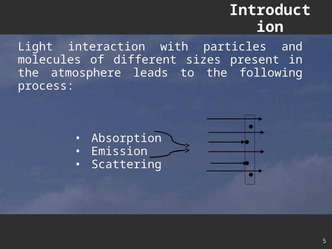
Light interaction with particles and molecules of different sizes present in the atmosphere leads to the following process:
• Absorption• Emission• Scattering
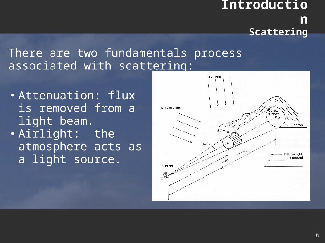
There are two fundamentals process associated with scattering:
IntroductionScattering
• Attenuation: flux is removed from a light beam.
• Airlight: the atmosphere acts as a light source.
6
7
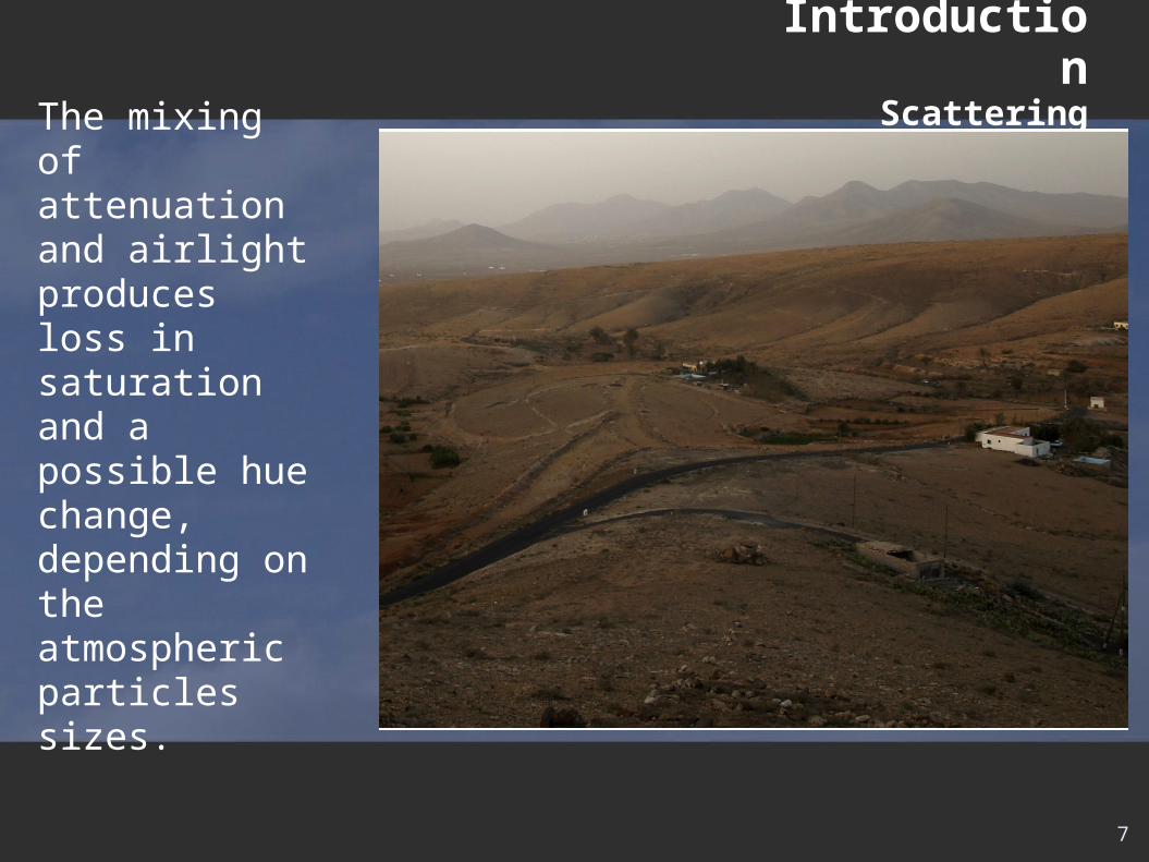
The mixing of attenuation and airlight produces loss in saturation and a possible hue change, depending on the atmospheric particles sizes.
IntroductionScattering
8
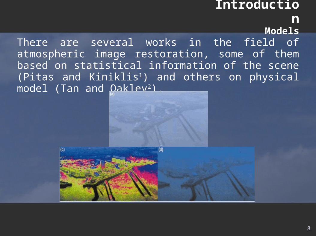
There are several works in the field of atmospheric image restoration, some of them based on statistical information of the scene (Pitas and Kiniklis1) and others on physical model (Tan and Oakley2).
IntroductionModels
The physics based models usually need information about meteorological conditions (Yitzhaky et al.3), distances from the objects (Narasimhan and Nayar4) or some images taken under different weather conditions (Narasimhan and Nayar6).
The better physics based models are those constructed over the dichromatic model (Narasimhan and Nayar7).
IntroductionModels
9
10
Contents
• Introduction • Physical model• Method• Colour changes in the object with observation distance• Conclusions and future work• References
11
Physical Model
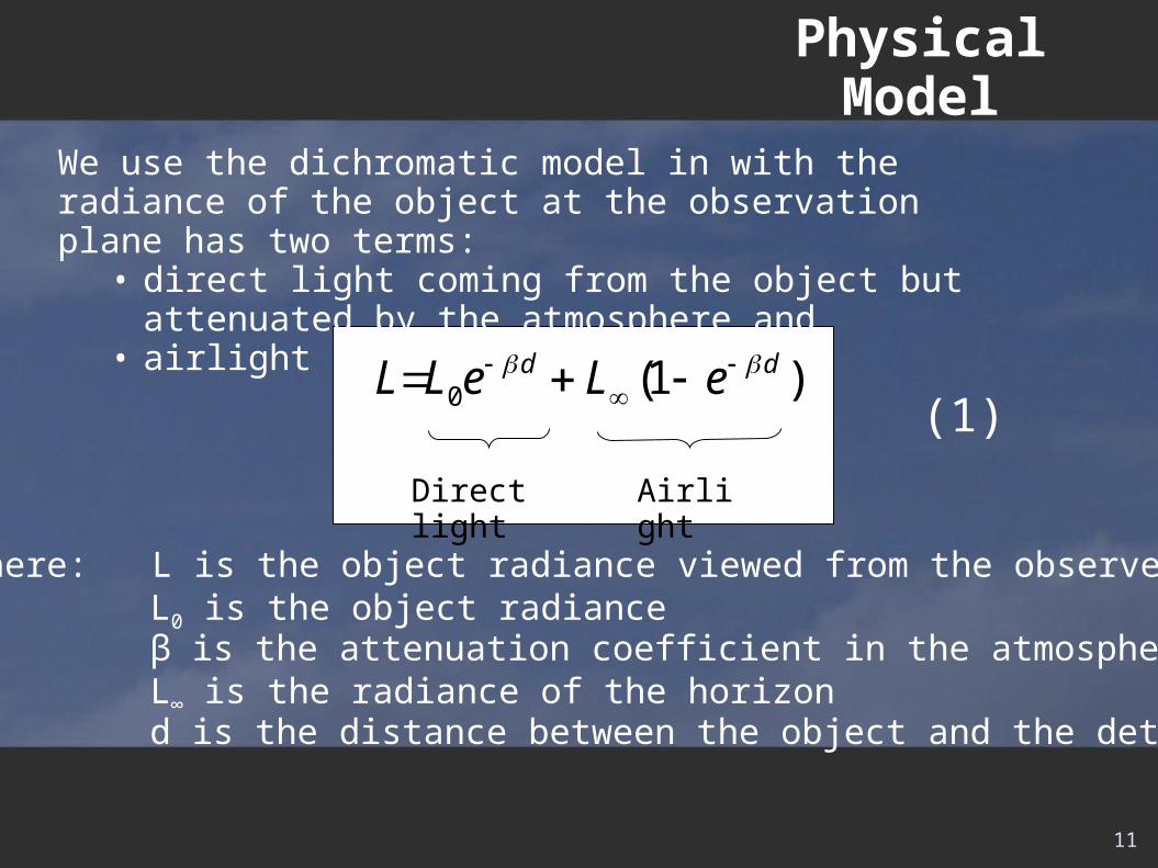
We use the dichromatic model in with the radiance of the object at the observation plane has two terms:
• direct light coming from the object but attenuated by the atmosphere and
• airlight
Where: L is the object radiance viewed from the observer plane L0 is the object radiance β is the attenuation coefficient in the atmosphere L∞ is the radiance of the horizon d is the distance between the object and the detector
Direct light Airlight
0 (1 )d dL L e L e
(1)
12
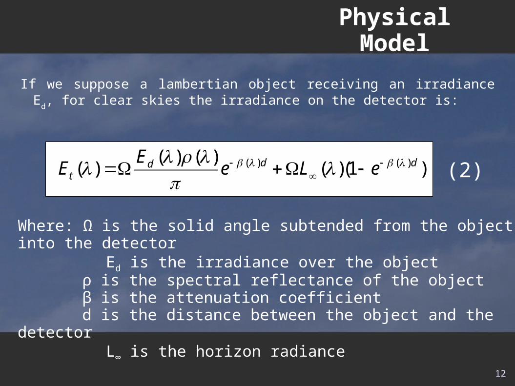
If we suppose a lambertian object receiving an irradiance Ed, for clear skies the irradiance on the detector is:
Physical Model
(2)( ) ( )( ) ( )( ) ( )(1 )d ddt
EE e L e
Where: Ω is the solid angle subtended from the object into the detector Ed is the irradiance over the object
ρ is the spectral reflectance of the object β is the attenuation coefficient d is the distance between the object and the detector
L∞ is the horizon radiance
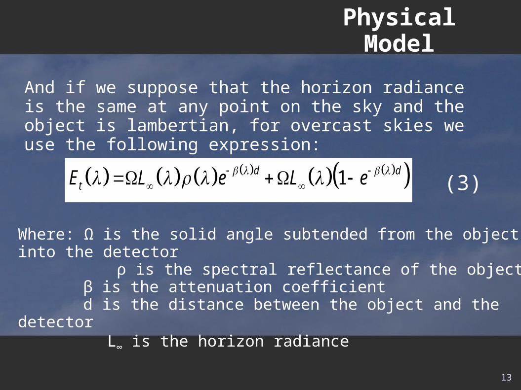
And if we suppose that the horizon radiance is the same at any point on the sky and the object is lambertian, for overcast skies we use the following expression:
1d dtE L e L e
(3)
Physical Model
13
Where: Ω is the solid angle subtended from the object into the detector ρ is the spectral reflectance of the object
β is the attenuation coefficient d is the distance between the object and the detector
L∞ is the horizon radiance

14
Contents
• Introduction • Physical model• Method• Colour changes in the object with observation distance• Conclusions and future work• References
15
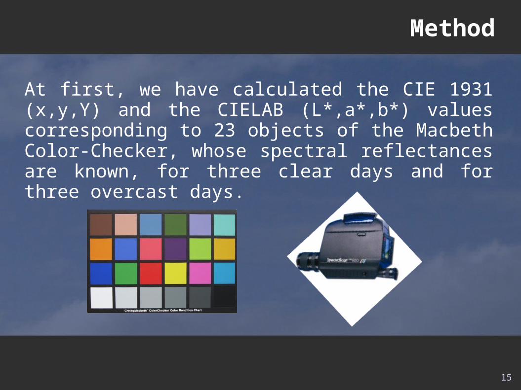
Method
At first, we have calculated the CIE 1931 (x,y,Y) and the CIELAB (L*,a*,b*) values corresponding to 23 objects of the Macbeth Color-Checker, whose spectral reflectances are known, for three clear days and for three overcast days.
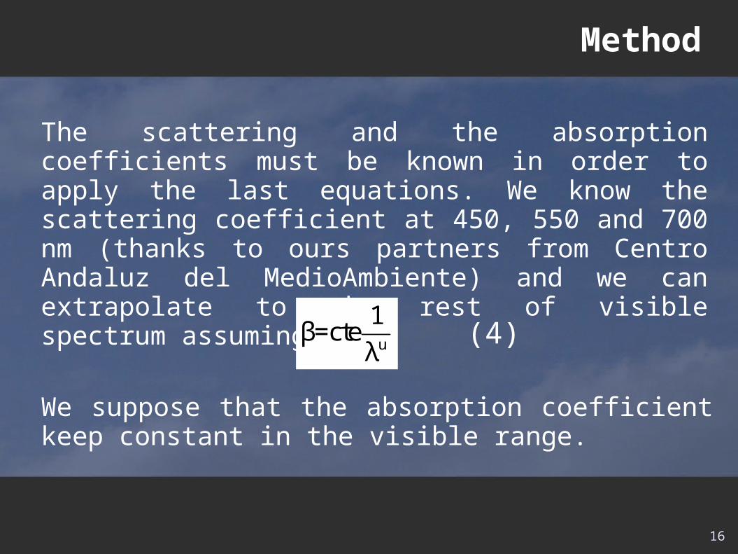
The scattering and the absorption coefficients must be known in order to apply the last equations. We know the scattering coefficient at 450, 550 and 700 nm (thanks to ours partners from Centro Andaluz del MedioAmbiente) and we can extrapolate to the rest of visible spectrum assuming that:
Method
u
1β=cte
λ
We suppose that the absorption coefficient keep constant in the visible range.
(4)
16
Method
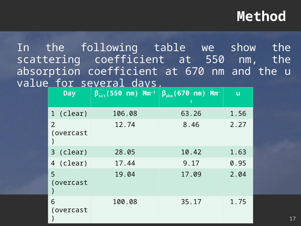
In the following table we show the scattering coefficient at 550 nm, the absorption coefficient at 670 nm and the u value for several days.
Day βsct(550 nm) Mm-1 βabs(670 nm) Mm-1 u
1 (clear) 106.08 63.26 1.56
2 (overcast) 12.74 8.46 2.27
3 (clear) 28.05 10.42 1.63
4 (clear) 17.44 9.17 0.95
5 (overcast) 19.04 17.09 2.04
6 (overcast) 100.08 35.17 1.75
17
18
Contents
• Introduction • Physical model• Method• Colour changes in the object with observation distance• Conclusions and future work• References
19
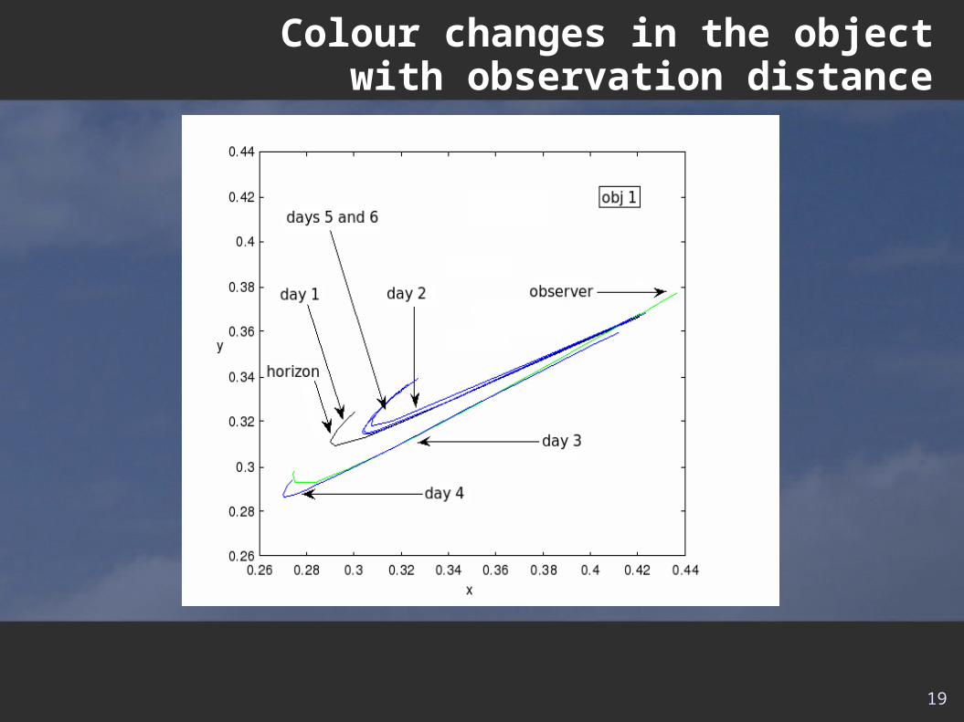
Colour changes in the object with observation distance
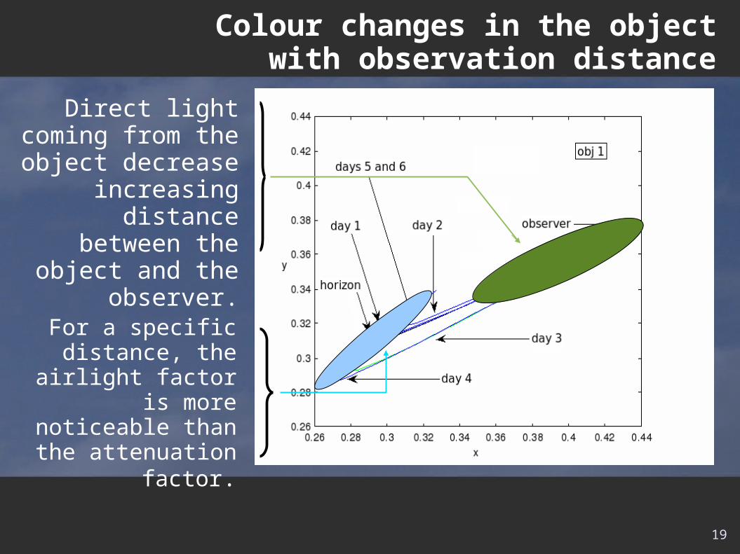
Direct light coming from the object
decrease increasing distance between the object and the
observer.
For a specific distance, the airlight
factor is more noticeable than the attenuation factor.
19
Colour changes in the object with observation distance
20
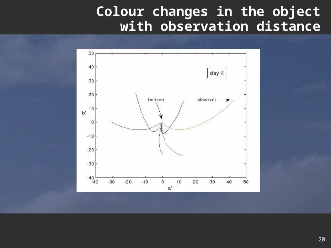
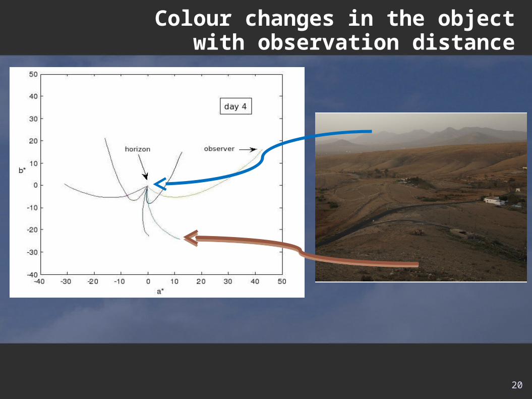
Colour changes in the object with observation distance
20
Colour changes in the object with observation distance
21
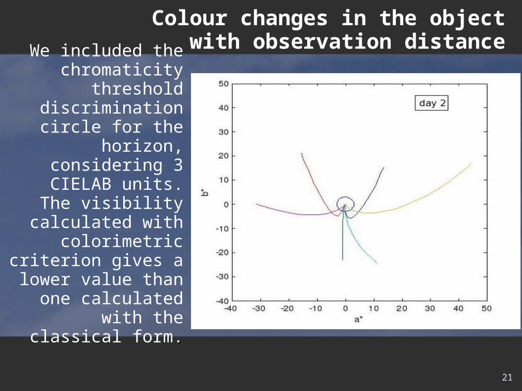
We included the chromaticity threshold
discrimination circle for the horizon, considering
3 CIELAB units.The visibility calculated
with colorimetric criterion gives a lower
value than one calculated with the
classical form..
Colour changes in the object with observation distance
22
Contents
• Introduction • Physical model• Method• Colour changes in the object with observation distance• Conclusions and future work• References
In this work we pretend to study the influence of the atmosphere in the objects color with the distance. Making a computational work based on a physical model we see how the objects loose their chromaticity.
For future work we pretend make more measures, including more meteorological conditions and improve the theoretical model.
Conclusions and future work
23
24
Contents
• Introduction • Physical model• Method• Colour changes in the object with observation distance• Conclusions and future work• References
25
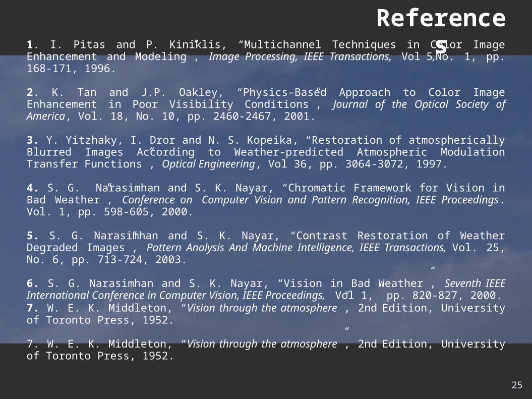
References1. I. Pitas and P. Kiniklis, “Multichannel Techniques in Color Image Enhancement and Modeling”, Image Processing, IEEE Transactions, Vol 5,No. 1, pp. 168-171, 1996.
2. K. Tan and J.P. Oakley, “Physics-Based Approach to Color Image Enhancement in Poor Visibility Conditions”, Journal of the Optical Society of America, Vol. 18, No. 10, pp. 2460-2467, 2001.
3. Y. Yitzhaky, I. Dror and N. S. Kopeika, “Restoration of atmospherically Blurred Images According to Weather-predicted Atmospheric Modulation Transfer Functions”, Optical Engineering, Vol 36, pp. 3064-3072, 1997.
4. S. G. Narasimhan and S. K. Nayar, “Chromatic Framework for Vision in Bad Weather”, Conference on Computer Vision and Pattern Recognition, IEEE Proceedings. Vol. 1, pp. 598-605, 2000.
5. S. G. Narasimhan and S. K. Nayar, “Contrast Restoration of Weather Degraded Images”, Pattern Analysis And Machine Intelligence, IEEE Transactions, Vol. 25, No. 6, pp. 713-724, 2003.
6. S. G. Narasimhan and S. K. Nayar, “Vision in Bad Weather”, Seventh IEEE International Conference in Computer Vision, IEEE Proceedings, Vol 1, pp. 820-827, 2000.7. W. E. K. Middleton, “Vision through the atmosphere”, 2nd Edition, University of Toronto Press, 1952.
7. W. E. K. Middleton, “Vision through the atmosphere”, 2nd Edition, University of Toronto Press, 1952.

Thank you for your attention!