column failures (credit for many illustrations is given to mcgraw hill publishers and an array of...
TRANSCRIPT

Column Failures (Credit for many illustrations is given to McGraw Hill publishers and an array of
internet search results)

Parallel Reading
10.1 Introduction10.2 Euler Buckling Load10.3 The Affect of End Conditions10.4 Eccentric Loading10.7 Design of Centrally Loaded Columns(Do Chapter 10 Reading Assignment Problems)
Chapter 10

Failed Columns
The Rush of the Crush The Shear Joy of It Wait a MinuteBack-UpThis is not Supposeto happen.

There Appears to be Another Mode by Which Columns Fail
Buckling Failures

We Find Columns in Some Unexpected Places

Can You Explain Why Somebody Would Brace a Floor in this Manner

One of Our Assumptions Has Been that Deformation Does not Change
Geometry
BBut if the Columnever deformsenough to affectgeometry we seeour eccentric loadingproblem formingagain.

The Stiffness and Inertia of the Column to Spring Back Becomes
Critical
A solution to this restriction is

The Term is Called Eulers Buckling Equation
Where

And r is the Radius of Gyration
A
Ir

So Lets Take Our Formula for a Test Drive
If E = 200 GPaHow much of a load can I put on this puppybefore it buckles
The key formulawill be

Working on Our Formula
12
2*200* I
Pcr
Looks like the only missing term is I

Finishing Up

Assignment 17
• Do problem 10.2-1
• Do problem 10.2-2

So What Kind of Load Will it Take to Buckle this Column?
For very fat columnsthe load to shear ona 45 or to crush willcome before abuckling load.

Lets Try Another Application
A circular Brass Column 2 feet in diameter is required to handle the maximum load possible. How tall call the column be before we have to worry about it failing by buckling?
Brass Compression Strength 130 Ksi Shear Strength 36 Ksi Young’s Modulus 15,000,000 psi

Lets See What it Will Take to Fail it In Compression or Shear
130,000 psi
Shear max will be 65,000 psi which is over the 36,000 psi we have available. The column will shear first.
I will trick Mohr’s Circle into giving me the answer
τ
σσ
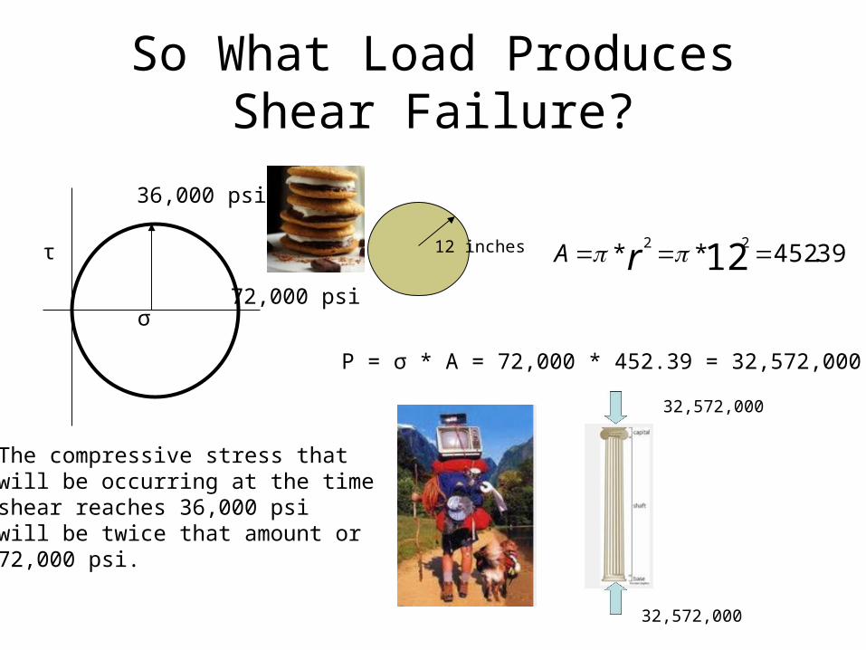
So What Load Produces Shear Failure?
12 inches 39.452** 1222 rA
36,000 psi
τ
σ72,000 psi
The compressive stress thatwill be occurring at the timeshear reaches 36,000 psiwill be twice that amount or72,000 psi.
P = σ * A = 72,000 * 452.39 = 32,572,000 lbs
32,572,000
32,572,000

Now We Get Ready to Solve Euler’s Buckling Equation for
Length
000,572,32
*000,000,15***22
IIEL
Pcr
Looks like we need to find I

I for a Circle
12 inches
I = 16,286 in4
000,572,32
*000,000,15***22
IIEL
Pcr
= 272 inches = 22 ft 8 inches

The Model Used for Eulers Buckling Equation Assumed Pin
Connected Ends
This is certainly a worse case scenario becausethe column is getting no help from its’surroundings.
But columns frequentlyappear much moreconfined than a pinconnection.

Extending Eulers Equation
If one end is confinedand the other is freeto move the columncan be only half as longas the equationindicates
(I’m looking forEffective Lengths)
I imagine there is a reason you don’t see alot of buildings built this way on purpose.

More Cases
If we stop the upper end from swinging,even if it is free to pivot then only 70% ofthe column length is considered inEuler’s Equation. A longer column ispossible.

Of Course the Best Case is to Confine Both Ends
Now we can double the column length.
Not surprisingly this ishow we try to designstructures.

Lets Try an Application
This column design is fully constrained at thebase, but for rotation about the z axis it is pinconnected on top and for rotation about the yaxis it is unconstrained.
The column is aluminum
What ratio of a to b will give the maximum bending resistance with the leastMaterial?

Looking at Eulers Buckling Equation for critical stress
We will be the most efficient with material when the critical stress forcolumn buckling is the same in both directions.
Obviously when the slendernessratio in the two directions is thesame the condition is satisfied.
Slenderness ratio

Lets Pick-Off the Effective Length Terms
Around theY axis weareunconstrainedso Le = 2*L
But around theZ axis we arepin connectedso Le = 0.7*L

Finding the Radius of Gyration about the Z axis
a
b

Now for the Radius of Gyration about the Y axis
b
a

Equate the Slenderness Ratios

Assignment 18
• Problem 10.3-1

For Our Next What If
What if someone loads the columnOff-Center?

Answer
We can equate a load that isOff-Center by a distance eas the same load at the centerplus a bending moment equalto the load times the off-centerdistance e.

Some Ugly Math
We’ll take derivativesOn that deflection distance
English translation – the column just buckled it two.

The Equation Allows Us to Get Critical Measurements and Loads
Remember.
A
h
b
Called the Secant Formula

It Provides a Rather Smoothed Curve

Lets Try Some Problems and See How this Thing Works
Once upon a time there lived aColumn of structural tubing withThe properties shown below.One day the good witch wantedto know how much of a loadcould be placed on the columnand still allow a factor of safetyof 2 against buckling. Along camethe good engineering studentto help the good witch find theanswer.

We Observe how the column is fixed
Fixed bottom, free movementAt top. So

Plugging into Eulers Buckling Equation
given
From effectiveLength calculation

Adjusting for Our Factor of Safety

But the Story Continues
Next a bad witch came along.The bad witch was very drunkAnd placed the load 0.75 inFrom the column center whereIt was suppose to be placed.Now how much load can theColumn take before failure?

Now We Use the Secant Formula
AA little error in loading made a big difference in stress(I wonder whether this explains why Engineers use safety factors)?
Note ourP/Pcr comesFrom 2 safetyfactor

Assignment 19
• Do Problem 10.4-2
• Do Problem 10.4-4

Of Course Real World Loading Scenarios are not perfect
Columns are not perfectly fabricated
Empirical results tend toFollow more of a smoothCurve.

Manufactures Have Empirical Guidelines for Materials
This empirical design formula is forAluminum
For
Dividing lineIs L/r = 66
C1 = 20.2 for Ksi or 139 for MPa
C2 = 0.126 for Ksi or 0.868 for MPa
C3 = 51,000 Ksi or 351,000 MPa
Where L is the column length
r is the radius of gyration
And L/r is the slenderness ratio

Different Materials or Formulations Have Different Guidelines
This empirical design formula is forAluminum
For
Dividing lineIs L/r = 55
C1 = 30.7 for Ksi or 212 for MPa
C2 = 0.23 for Ksi or 1.585 for MPa
C3 = 54,000 Ksi or 372,000 MPa
Where L is the column length
r is the radius of gyration
And L/r is the slenderness ratio

We Can Get Some Interesting Twists
Greater than 55I’m design r
I will use a formula basedon L/r
I don’t know r so I can’t knowwhich formula

Try this for a SolutionL/r must either be greater than or less than 55
Take a guess – in this case we will try >55
Use that formula to solve for r
Plug into L/r and see if your guess about L/rwas right.
If it was – you are done
If it was not – use the other formula

So We are off to the races
Using the L/r >55 formula
750 mm
Radius of Gyration fora circle
Check out the SlendernessRatio

Assignment 20
• Problem 10.7-14