combi b pc software 8213x installation and operating instructions
TRANSCRIPT
Combi B PC software 8213X
Installation and operating instructions
EN

Version 11/28/2013 Page 2 of 13
Installation and operating instructions Combi B PC software 8213X
Table of Contents
1 Important notes .................................................................................................................................................. 3
2 Glossary of abbreviations and terms............................................................................................................... 4
3 Symbols and special font types used .............................................................................................................. 5
4 Scope of delivery and functionalities .............................................................................................................. 5
4.1 Audit software ............................................................................................................................................................. 6
4.2 Programming software ............................................................................................................................................... 6
5 Installation of the PC software ......................................................................................................................... 6
6 Starting the PC software and establishing a connection to the lock ........................................................... 6
6.1 Initialization by means of the master code. .............................................................................................................. 7
6.2 Initialization by means of the inspection key............................................................................................................ 8
7 Disconnecting the lock from the PC ................................................................................................................ 8
8 Setting the language .......................................................................................................................................... 9
9 Reading out the audit ........................................................................................................................................ 9
10 Programming the lock via software (with dongle only) ............................................................................... 10
10.1 Time ............................................................................................................................................................................ 10
10.2 OD/OST (opening delay/opening stand-by time) .................................................................................................... 11
10.3 Options ....................................................................................................................................................................... 11
10.4 Authorizations ........................................................................................................................................................... 12
11 Exporting and importing configurations ....................................................................................................... 12
11.1 Exporting a configuration ......................................................................................................................................... 12
11.2 Importing a configuration ......................................................................................................................................... 12
12 Partial commissioning of the lock .................................................................................................................. 13
A Notes ................................................................................................................................................................. 13
List of Figures
Figure 1: Mini USB interface at the input unit .................................................................................................................................. 6 Figure 2: Selection of the lock ......................................................................................................................................................... 7 Figure 3: Confirming the Audit mode of the lock at the PC ............................................................................................................. 7 Figure 4: Entering the valid master code ........................................................................................................................................ 7 Figure 5: Disconnecting the connection to the lock ......................................................................................................................... 8 Figure 6: Setting the language ........................................................................................................................................................ 9 Figure 7: Selecting the language .................................................................................................................................................... 9 Figure 8: Reading out the audit ....................................................................................................................................................... 9 Figure 9: Time tab ......................................................................................................................................................................... 10 Figure 10: OD/OST tab (opening delay/opening stand-by time) ................................................................................................... 11 Figure 11: Options tab .................................................................................................................................................................. 11 Figure 12: Authorizations tab ........................................................................................................................................................ 12 Figure 13: Exporting a configuration ............................................................................................................................................. 12 Figure 14: Importing a configuration ............................................................................................................................................. 12
List of Tables
Table 1: Symbols ............................................................................................................................................................................ 5 Table 2: Initializing the software connection by means of the master code .................................................................................... 7 Table 3: Initializing the software connection by means of the inspection key ................................................................................. 8
Version 11/28/2013 Page 3 of 13
Installation and operating instructions Combi B PC software 8213X
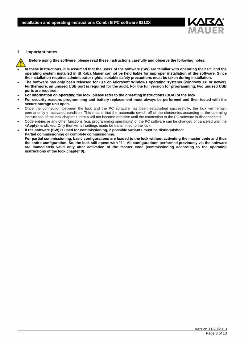
1 Important notes
Before using this software, please read these instructions carefully and observe the following notes:
In these instructions, it is assumed that the users of the software (SW) are familiar with operating their PC and the operating system installed in it! Kaba Mauer cannot be held liable for improper installation of the software. Since the installation requires administrator rights, suitable safety precautions must be taken during installation.
The software has only been released for use on Microsoft Windows operating systems (Windows XP or newer). Furthermore, an unused USB port is required for the audit. For the full version for programming, two unused USB ports are required.
For information on operating the lock, please refer to the operating instructions (BDA) of the lock.
For security reasons programming and battery replacement must always be performed and then tested with the secure storage unit open.
Once the connection between the lock and the PC software has been established successfully, the lock will remain permanently in activated condition. This means that the automatic switch-off of the electronics according to the operating instructions of the lock chapter 1 item 4 will not become effective until the connection to the PC software is disconnected.
Code entries or any other functions (e.g. programming operations) of the PC software can be changed or canceled until the <Apply> is clicked. Only then will all settings made be transmitted to the lock.
If the software (SW) is used for commissioning, 2 possible variants must be distinguished: Partial commissioning or complete commissioning. For partial commissioning, basic configurations are loaded to the lock without activating the master code and thus the entire configuration. So, the lock still opens with "1". All configurations performed previously via the software are immediately valid only after activation of the master code (commissioning according to the operating instructions of the lock chapter 8).
Version 11/28/2013 Page 4 of 13
Installation and operating instructions Combi B PC software 8213X
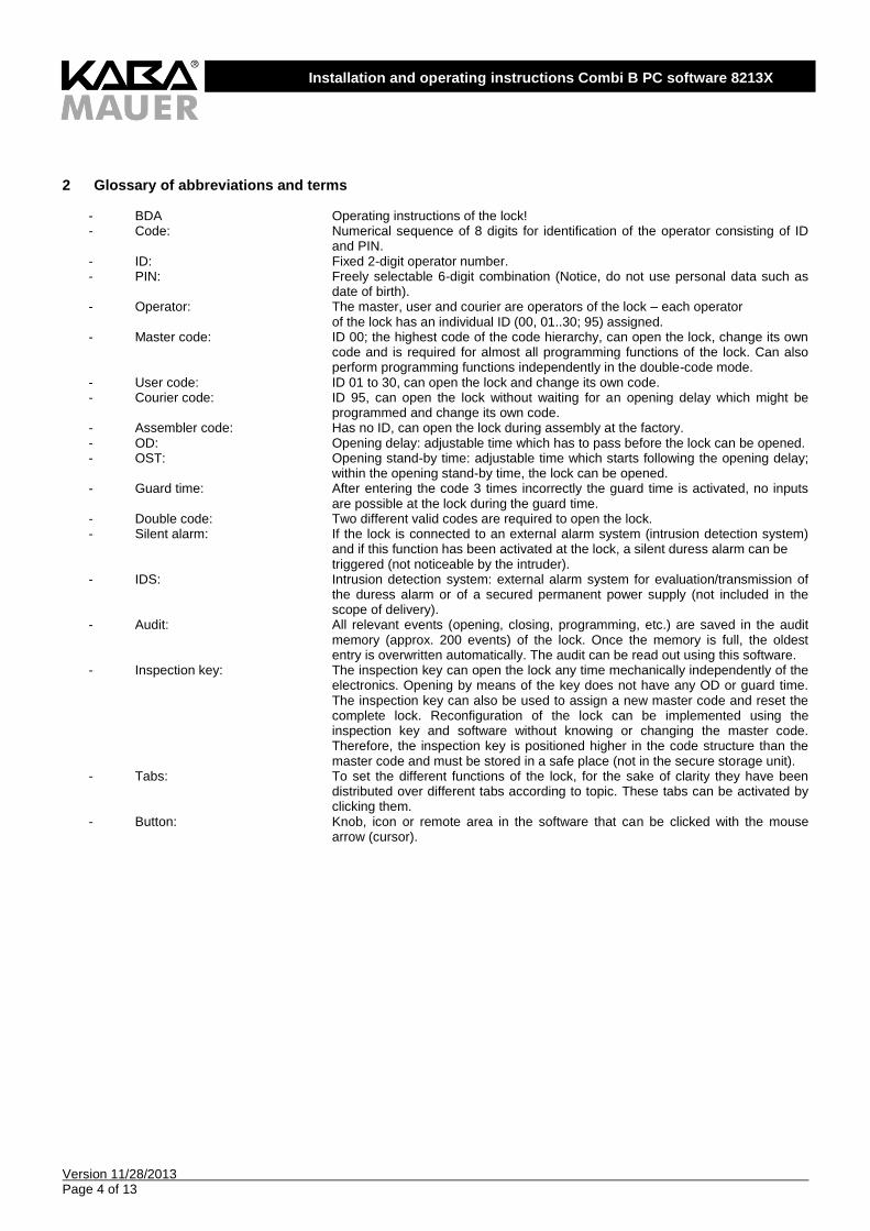
2 Glossary of abbreviations and terms
- BDA Operating instructions of the lock! - Code: Numerical sequence of 8 digits for identification of the operator consisting of ID
and PIN. - ID: Fixed 2-digit operator number. - PIN: Freely selectable 6-digit combination (Notice, do not use personal data such as
date of birth). - Operator: The master, user and courier are operators of the lock – each operator
of the lock has an individual ID (00, 01..30; 95) assigned. - Master code: ID 00; the highest code of the code hierarchy, can open the lock, change its own
code and is required for almost all programming functions of the lock. Can also perform programming functions independently in the double-code mode.
- User code: ID 01 to 30, can open the lock and change its own code. - Courier code: ID 95, can open the lock without waiting for an opening delay which might be
programmed and change its own code. - Assembler code: Has no ID, can open the lock during assembly at the factory. - OD: Opening delay: adjustable time which has to pass before the lock can be opened. - OST: Opening stand-by time: adjustable time which starts following the opening delay;
within the opening stand-by time, the lock can be opened. - Guard time: After entering the code 3 times incorrectly the guard time is activated, no inputs
are possible at the lock during the guard time. - Double code: Two different valid codes are required to open the lock. - Silent alarm: If the lock is connected to an external alarm system (intrusion detection system)
and if this function has been activated at the lock, a silent duress alarm can be triggered (not noticeable by the intruder).
- IDS: Intrusion detection system: external alarm system for evaluation/transmission of the duress alarm or of a secured permanent power supply (not included in the scope of delivery).
- Audit: All relevant events (opening, closing, programming, etc.) are saved in the audit memory (approx. 200 events) of the lock. Once the memory is full, the oldest entry is overwritten automatically. The audit can be read out using this software.
- Inspection key: The inspection key can open the lock any time mechanically independently of the electronics. Opening by means of the key does not have any OD or guard time. The inspection key can also be used to assign a new master code and reset the complete lock. Reconfiguration of the lock can be implemented using the inspection key and software without knowing or changing the master code. Therefore, the inspection key is positioned higher in the code structure than the master code and must be stored in a safe place (not in the secure storage unit).
- Tabs: To set the different functions of the lock, for the sake of clarity they have been distributed over different tabs according to topic. These tabs can be activated by clicking them.
- Button: Knob, icon or remote area in the software that can be clicked with the mouse arrow (cursor).

Version 11/28/2013 Page 5 of 13
Installation and operating instructions Combi B PC software 8213X
3 Symbols and special font types used In the instructions, different symbols and fonts are used (see below). Key presses on the keypad of the lock are always represented as a key symbol (e.g.: ). Likewise, feedbacks of the input unit, such as LEDs or tones, are represented as
symbols (e.g.: ).
In contrast, buttons to be pressed in the PC software are represented as bold text between the symbols < and > (e.g. <XXXX>).
Terms, options and tabs of the PC software are represented in italics with inverted commas (e.g. "XXXX").
In the further course of the instructions, the distinction between the PC software and the input input will no longer be mentioned, since the corresponding symbols and fonts can be clearly assigned to either of them.
Symbols / Special font types Meaning
Warning
NOTICE
Note
Symbol for 2-digit code ID (see also chapter 2) on making entries at the input unit
Symbol for individual numeric keys when entering the code at the input unit
Action performed
Action not performed
Short green LED signal from the input unit
Permanent green LED signal from the input unit
Short red LED signal from the input unit
Signal buzzer from the input unit
<XXXX> Button to be pressed in the PC software
"XXXXX" Option, tab or term from the PC software
Table 1: Symbols
4 Scope of delivery and functionalities Two software packages are on offer: the audit software package and the programming software. The two packages differ with respect to both the scope of delivery and their functionalities. These instructions describe the functionalities of both packages. When purchasing the audit software, the functions described in chapters 10 and 12 cannot be executed.
Version 11/28/2013 Page 6 of 13
Installation and operating instructions Combi B PC software 8213X
4.1 Audit software
The functionalities of the audit software are restricted to reading out, exporting and importing the audit (for details, see chapter 9). The audit software is available under the Kaba Mauer item number 82132Z0007. The scope of delivery includes:
1) Installation CD, incl. instructions 2) CB 30 PC stick 3) USB extension cord 2m
4.2 Programming software
In addition to the functions of the audit software, the programming software contains functions for programming the Combi B 30 lock (see chapters 10 and 12). This makes it possible to program the lock also via the software instead of the keypad (operator, double code, silent alarm, etc.). The complete programming software is available under the Kaba Mauer item number 82132Z0001. The scope of delivery includes:
1) Installation CD, incl. instructions 2) CB 30 PC stick 3) USB extension cord 2m 4) Dongle
5 Installation of the PC software
The installation of the software on a PC with Windows system requires administrator rights. For a first installation, insert Kaba Mauer CD into the drive of the target computer. If the installation is not started automatically from the CD, switch to the main directory of the CD drive and start the Setup.exe file.
Now select the target folder of the installation and confirm <Install>. The remaining installation proceeds automatically.
After successful completion of the installation, both the start menu and the desktop contain links that allow the program to be started. If during installation or commissioning of the software error messages occur, please first contact your administrator. If he is unable to solve the problem, please contact Kaba Mauer GmbH, giving an exact error description (the contact data can be found at www.kaba-mauer.de). We recommend a regular check of the software for updates. Whether a newer software version is available, can be found out by opening in your browser the Kaba Mauer website (www.kaba-mauer.de), opening the Combi B 30 under Products and clicking on "Software". There you can compare the software version with the installed version. If the version on the website is more up-to-date, download it and install it on your PC in the same way in which you installed it from the CD.
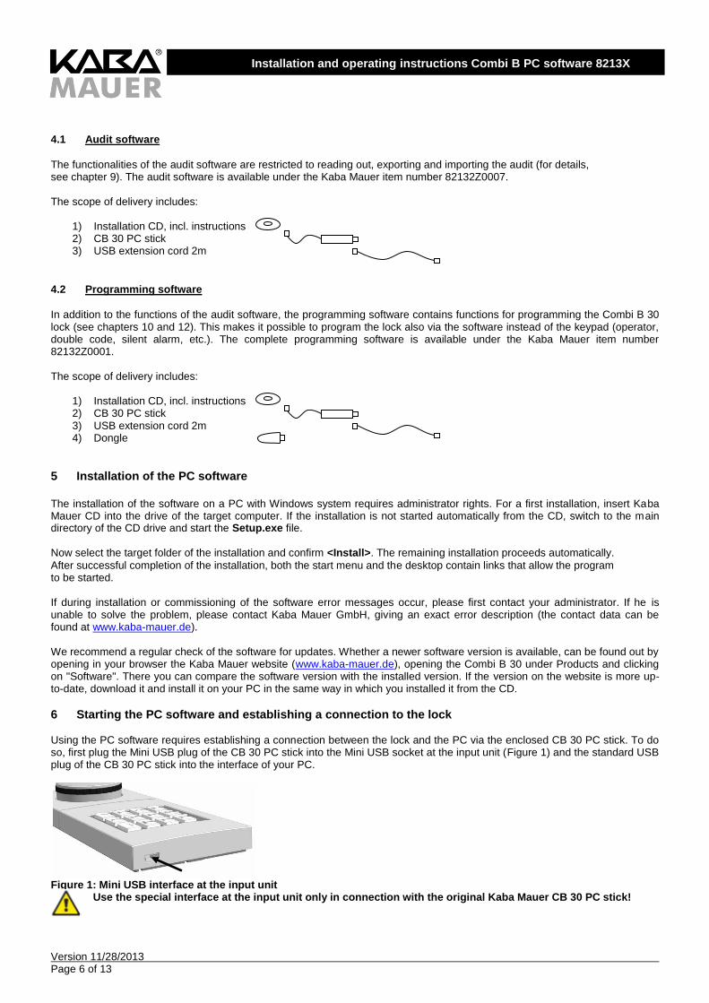
6 Starting the PC software and establishing a connection to the lock Using the PC software requires establishing a connection between the lock and the PC via the enclosed CB 30 PC stick. To do so, first plug the Mini USB plug of the CB 30 PC stick into the Mini USB socket at the input unit (Figure 1) and the standard USB plug of the CB 30 PC stick into the interface of your PC.
Figure 1: Mini USB interface at the input unit
Use the special interface at the input unit only in connection with the original Kaba Mauer CB 30 PC stick!
Version 11/28/2013 Page 7 of 13
Installation and operating instructions Combi B PC software 8213X
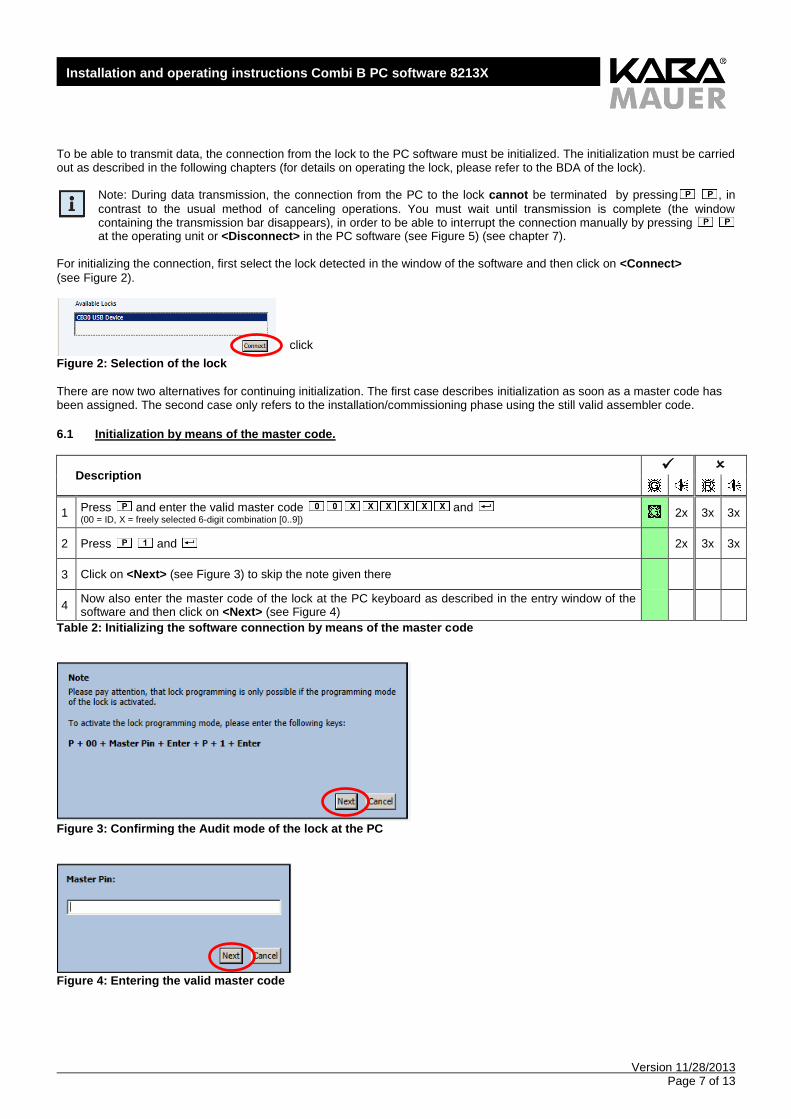
To be able to transmit data, the connection from the lock to the PC software must be initialized. The initialization must be carried out as described in the following chapters (for details on operating the lock, please refer to the BDA of the lock).
Note: During data transmission, the connection from the PC to the lock cannot be terminated by pressing , in
contrast to the usual method of canceling operations. You must wait until transmission is complete (the window containing the transmission bar disappears), in order to be able to interrupt the connection manually by pressing at the operating unit or <Disconnect> in the PC software (see Figure 5) (see chapter 7).
For initializing the connection, first select the lock detected in the window of the software and then click on <Connect>
(see Figure 2).
Figure 2: Selection of the lock
There are now two alternatives for continuing initialization. The first case describes initialization as soon as a master code has been assigned. The second case only refers to the installation/commissioning phase using the still valid assembler code.
6.1 Initialization by means of the master code.
Description
1 Press and enter the valid master code and (00 = ID, X = freely selected 6-digit combination [0..9]) 2x 3x 3x
2 Press and
2x 3x 3x
3 Click on <Next> (see Figure 3) to skip the note given there
4 Now also enter the master code of the lock at the PC keyboard as described in the entry window of the software and then click on <Next> (see Figure 4)
Table 2: Initializing the software connection by means of the master code
Figure 3: Confirming the Audit mode of the lock at the PC
Figure 4: Entering the valid master code
click
Version 11/28/2013 Page 8 of 13
Installation and operating instructions Combi B PC software 8213X
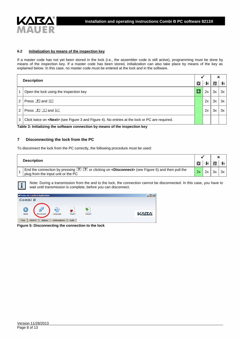
6.2 Initialization by means of the inspection key
If a master code has not yet been stored in the lock (i.e., the assembler code is still active), programming must be done by means of the inspection key. If a master code has been stored, initialization can also take place by means of the key as explained below. In this case, no master code must be entered at the lock and in the software.
Description
1 Open the lock using the inspection key 2x 3x 3x
2 Press and
2x 3x 3x
2 Press and
2x 3x 3x
3 Click twice on <Next> (see Figure 3 and Figure 4). No entries at the lock or PC are required.
Table 3: Initializing the software connection by means of the inspection key
7 Disconnecting the lock from the PC To disconnect the lock from the PC correctly, the following procedure must be used:
Description
1 End the connection by pressing or clicking on <Disconnect> (see Figure 5) and then pull the
plug from the input unit or the PC 2x 2x 3x 3x
Note: During a transmission from the and to the lock, the connection cannot be disconnected. In this case, you have to wait until transmission is complete, before you can disconnect.
Figure 5: Disconnecting the connection to the lock

Version 11/28/2013 Page 9 of 13
Installation and operating instructions Combi B PC software 8213X
8 Setting the language To set the language, click on <Language> (see Figure 6). By clicking on <Arrow down> (see arrow in Figure 7), the available languages for selection are displayed. Click on your preferred language and then on <Apply> and the corresponding language
will be set.
Figure 6: Setting the language
Figure 7: Selecting the language
9 Reading out the audit
The Audit memory is the event memory of the lock in which approx. the last 200 events (operating and programming ) of the lock are stored. To read out the audit, initialize the connection to the software as described in chapter 6 . After the connection has been established successfully, the read-out process can be started on the Audit tab by pressing the <Start read-out> button (see Figure 8).
Figure 8: Reading out the audit
The audit is now transmitted to the PC software. Meanwhile the counter of the currently transmitted audit entry is shown in the left footer and the total number of available entries or entries to be transmitted on the right (see Figure 8 arrow mark). After reading out the audit, it can be exported into a file in TXT, XML or encrypted format and thus a CBE format that can no longer be changed in a folder of your choice by pressing the <Export Audit> button and thus be saved. At a later stage, the
Version 11/28/2013 Page 10 of 13
Installation and operating instructions Combi B PC software 8213X
encrypted audit can again be imported into the software by pressing the <Import Audit> button or the TXT or XML format can
be evaluated in a different program (e.g. MS Excel).
Note: If the clock in the lock is or was not set by means of the "Time" tab (only available in the programming software,
see chapter 4), no real times will be saved to the audit and output (see chapter 10.1). In this case, a relative time is displayed (the clock then starts in each case after a battery change with the date 01/01/13 and the time 00:00).
10 Programming the lock via software (with dongle only) To carry out programming by means of the PC software, plug the authorization dongle included in the scope of delivery of the programming software into an unused USB port and then start the SW. Next initialize the connection to the software as described in chapter 6. After the connection has been established successfully, the software will first read out automatically the current configuration of the lock. Now you can change the settings as described in the following chapters. This can be followed by transmitting the changed configuration to the lock by pressing the <Apply> button. The individual settings have been distributed over the "Time", "OD/OST" (opening delay/opening stand-by time), "Options" and "Authorizations" tabs.
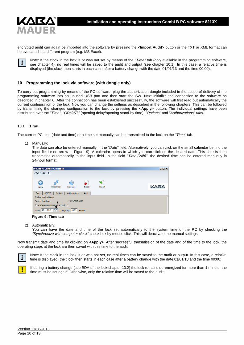
10.1 Time
The current PC time (date and time) or a time set manually can be transmitted to the lock on the "Time" tab.
1) Manually: The date can also be entered manually in the "Date" field. Alternatively, you can click on the small calendar behind the input field (see arrow in Figure 9). A calendar opens in which you can click on the desired date. This date is then transmitted automatically to the input field. In the field "Time (24h)", the desired time can be entered manually in
24-hour format.
Figure 9: Time tab
2) Automatically:
You can have the date and time of the lock set automatically to the system time of the PC by checking the "Synchronize with computer clock" check box by mouse click. This will deactivate the manual settings.
Now transmit date and time by clicking on <Apply>. After successful transmission of the date and of the time to the lock, the
operating steps at the lock are then saved with this time to the audit.
Note: If the clock in the lock is or was not set, no real times can be saved to the audit or output. In this case, a relative time is displayed (the clock then starts in each case after a battery change with the date 01/01/13 and the time 00:00). If during a battery change (see BDA of the lock chapter 13.2) the lock remains de-energized for more than 1 minute, the time must be set again! Otherwise, only the relative time will be saved to the audit.
Version 11/28/2013 Page 11 of 13
Installation and operating instructions Combi B PC software 8213X
10.2 OD/OST (opening delay/opening stand-by time)
The opening delay (0 - 99 minutes) and the opening stand-by time (0 - 19 minutes) can be set on the "OD/OST" tab and transmitted to the lock by clicking on <Apply> (see BDA of the lock chapter 9.3 opening delay and opening standby time).
Figure 10: OD/OST tab (opening delay/opening stand-by time)
Note: Both values (OD/OST) must be unequal to zero or, if this function is not desired, both values must be set to zero. Otherwise, this will result in an error message.
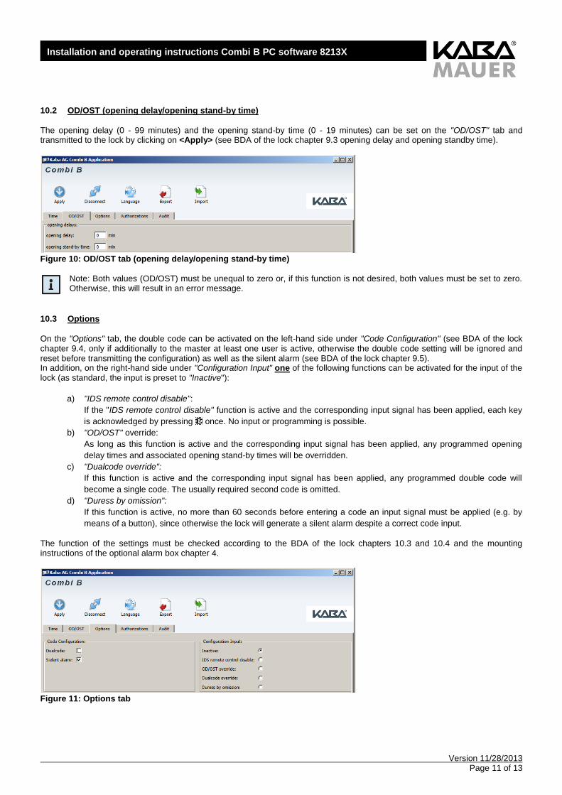
10.3 Options
On the "Options" tab, the double code can be activated on the left-hand side under "Code Configuration" (see BDA of the lock chapter 9.4, only if additionally to the master at least one user is active, otherwise the double code setting will be ignored and reset before transmitting the configuration) as well as the silent alarm (see BDA of the lock chapter 9.5). In addition, on the right-hand side under "Configuration Input" one of the following functions can be activated for the input of the lock (as standard, the input is preset to "Inactive"):
a) "IDS remote control disable":
If the "IDS remote control disable" function is active and the corresponding input signal has been applied, each key
is acknowledged by pressing once. No input or programming is possible.
b) "OD/OST" override:
As long as this function is active and the corresponding input signal has been applied, any programmed opening
delay times and associated opening stand-by times will be overridden.
c) "Dualcode override":
If this function is active and the corresponding input signal has been applied, any programmed double code will
become a single code. The usually required second code is omitted.
d) "Duress by omission":
If this function is active, no more than 60 seconds before entering a code an input signal must be applied (e.g. by
means of a button), since otherwise the lock will generate a silent alarm despite a correct code input.
The function of the settings must be checked according to the BDA of the lock chapters 10.3 and 10.4 and the mounting instructions of the optional alarm box chapter 4.
Figure 11: Options tab
Version 11/28/2013 Page 12 of 13
Installation and operating instructions Combi B PC software 8213X
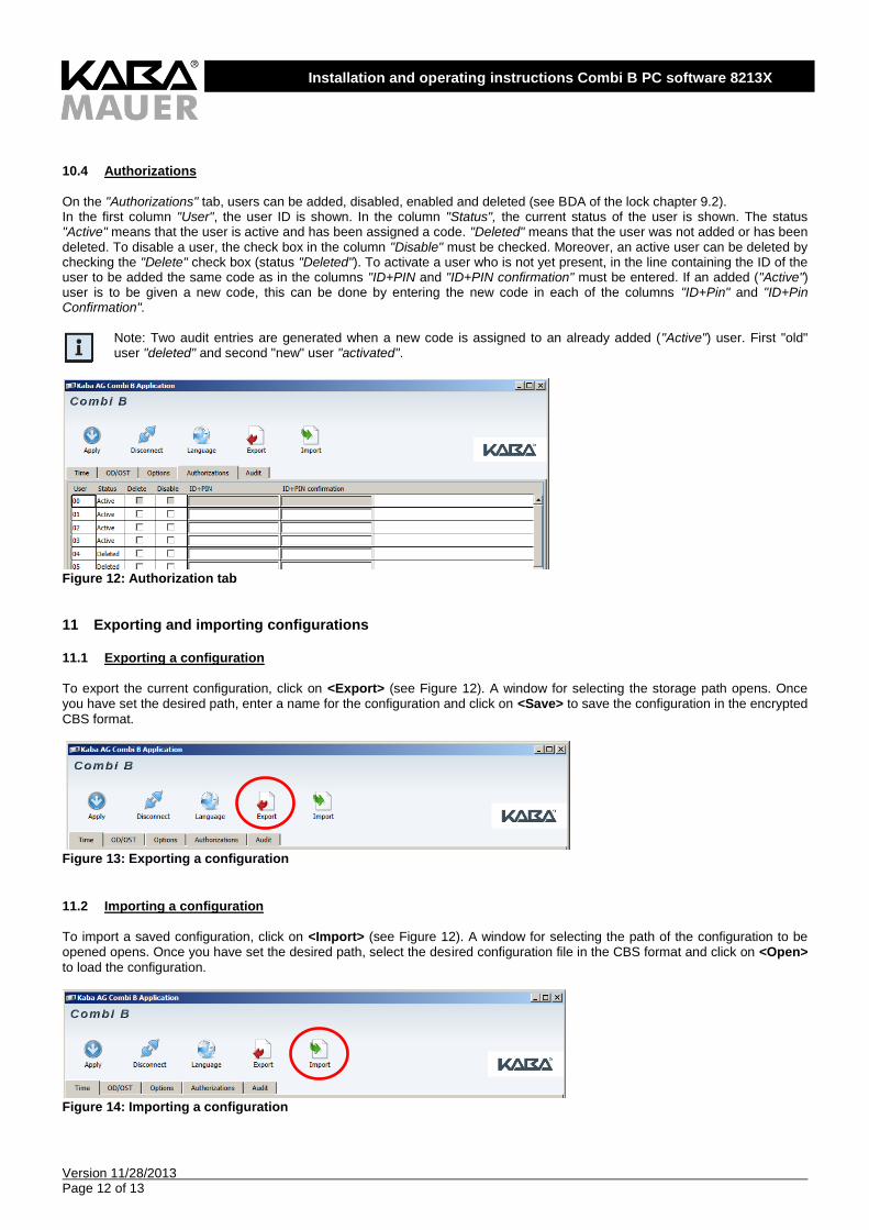
10.4 Authorizations
On the "Authorizations" tab, users can be added, disabled, enabled and deleted (see BDA of the lock chapter 9.2). In the first column "User", the user ID is shown. In the column "Status", the current status of the user is shown. The status "Active" means that the user is active and has been assigned a code. "Deleted" means that the user was not added or has been deleted. To disable a user, the check box in the column "Disable" must be checked. Moreover, an active user can be deleted by checking the "Delete" check box (status "Deleted"). To activate a user who is not yet present, in the line containing the ID of the user to be added the same code as in the columns "ID+PIN and "ID+PIN confirmation" must be entered. If an added ("Active") user is to be given a new code, this can be done by entering the new code in each of the columns "ID+Pin" and "ID+Pin Confirmation".
Note: Two audit entries are generated when a new code is assigned to an already added ("Active") user. First "old" user "deleted" and second "new" user "activated".
Figure 12: Authorization tab
11 Exporting and importing configurations
11.1 Exporting a configuration
To export the current configuration, click on <Export> (see Figure 12). A window for selecting the storage path opens. Once you have set the desired path, enter a name for the configuration and click on <Save> to save the configuration in the encrypted
CBS format.
Figure 13: Exporting a configuration
11.2 Importing a configuration
To import a saved configuration, click on <Import> (see Figure 12). A window for selecting the path of the configuration to be opened opens. Once you have set the desired path, select the desired configuration file in the CBS format and click on <Open>
to load the configuration.
Figure 14: Importing a configuration
Version 11/28/2013 Page 13 of 13
Installation and operating instructions Combi B PC software 8213X
12 Partial commissioning of the lock Partial commissioning is referred to a process in which a configuration is written into the lock without activating the associated functions. The precondition is that the lock is in the factory mode (lock opens displaying and ) and a programming software (see chapter 4.2) is available. The desired configuration is generated according to chapter 10 or imported according to chapter 11.2 and transmitted to the lock by pressing <Apply>, but it is not activated. This means that the lock will still open by
entering the assembler code. Partial commissioning has the advantage that the configuration is already being transmitted, but the lock still has to be opened via the assembler code for installation and test purposes. Accordingly, the lock externally still remains in factory mode (for operation, see BDA of the lock). The preset configuration will not be activated until a master code is set. If this type of configuration is to be done prior to delivery to the end customer, all configuration settings must be documented and communicated to the customer. For complete commissioning, follow the BDA of the lock (chapter 8).
A Notes
Kaba Mauer GmbH Frankenstrasse 8-12 D-42579 Heiligenhaus, Germany