combi-switch - dc disconnect and combiner … next standard fuse size would be a 12a, 600vdc fuse....
TRANSCRIPT

Combi-Switch Manual
i

Combi-Switch Manual
ii
Combi-Switch Manual
Copyright © 2009 SMA America, Inc. All rights reserved.
All rights reserved. No part of this document may be reproduced, stored in a retrievalsystem, or transmitted, in any form or by any means, electronic, mechanical,photographic, magnetic or otherwise, without the prior written permission of SMAAmerica, Inc.
SMA America makes no representations, express or implied, with respect to thisdocumentation or any of the equipment and/or software it may describe, including (withno limitation) any implied warranties of utility, merchantability, or fitness for any particularpurpose. All such warranties are expressly disclaimed. Neither SMA America nor itsdistributors or dealers shall be liable for any indirect, incidental, or consequential damagesunder any circumstances.
(The exclusion of implied warranties may not apply in all cases under some statutes, andthus the above exclusion may not apply.)
Specifications are subject to change without notice. Every attempt has been made tomake this document complete, accurate and up-to-date. Readers are cautioned,however, that SMA America reserves the right to make changes without notice and shallnot be responsible for any damages, including indirect, incidental or consequentialdamages, caused by reliance on the material presented, including, but not limited to,omissions, typographical errors, arithmetical errors or listing errors in the content material.
SMA America, Incorporated4031 Alvis Court
Rocklin, California 95677Tel +1 916 625 0870
Fax +11 916 625 0871www.SMA-America.com
Revision HistoryRev. No. Date By Description
1.0 Dec. 1, 2004 KS / JP Preliminary Release1.1 Dec. 10, 2004 JP Torque Update1.2 Aug. 2006 JP Wiring/Labeling Update1.3 Aug. 2006 JP Pos. Ground Update
iii

Combi-Switch Manual
IMPORTANT SAFETY INSTRUCTIONS*SAVE THESE INSTRUCTIONS*
This manual contains important instructions for the Combi-Switch that must be followed during the installation and use of the Combi-Switch.
The Combi-Switches are designed and tested according to international safety requirements, but as with all electrical and electronic equipment, certain precautions must be observed when installing the Combi-Switches. To reduce the risk of personal injury and to ensure the safe installation and operation of the Combi-Switches, you must carefully read and follow all instructions and warnings in this Installation Guide.
Safety and Hazard Symbols
This symbol is used to call attention to important information that you must have when installing and/or operating the Combi-Switches. Failure to read and follow instructions marked with this symbol could result in serious injury and/or damage to the equipment.
This symbol appears beside instructions and warnings that deal with dangerous voltages that can injure people who come in contact with them.
Warnings
WARNING: A Warning describes a hazard to equipment or personnel. It calls attention to a procedure or practice, which, if not correctly performed or adhered to, could result in damage to or destruction of part or all of the SMA equipment and/or other equipment connected to the SMA equipment or personal injury.
Warnings may also be accompanied by one or more of the safety and hazard symbols described above to indicate the type of hazard described therein.
Other Symbols
In addition to the safety and hazard symbols described previously, the following symbol is also used in this Installation Guide:
This symbol accompanies notes that call attention to supplementary information that you should know to ensure optimal operation of the system.
iv

Combi-Switch Manual
Warranty
All Combi-Switches sold in the USA have a one-year warranty, as indicated on the warranty card included in the shipping container. For warranty coverage, or if you have questions about the Combi-Switch warranty, contact SMA America at the address, telephone number, or Web site listed on page iii (to send E-mail, see the Contact section of the SMA America Web site: www.sma-america.com).
WARNING: All electrical installation must be done in accordance with the National Electrical Code ANSI/NFPA 70, local building codes and the requirements of the authority having jurisdiction.
WARNING:To prevent electrical shock or injury, all wiring and com-missioning procedures must be performed by qualified personnel.
WARNING: Before installing or using the Combi-Switch, read all of the instructions and warnings on the Combi-Switch and in this Installation Guide.
WARNING: PV arrays produce electrical energy when exposed to light and thus create an electrical shock hazard.
This GROUND symbol marks areas in the Combi-Switch for connecting equipment grounds only.
v

Combi-Switch Manual
This page intentionally left blank.
vi

Combi-Switch Manual Introduction
IntroductionSMA America’s Combi-Switches integrate PV series string fuses into a standard heavy-duty DC disconnect switch.
Combi-Switch features include:
• Visible blade, lockable DC disconnect switch• Four 10A, 600 VDC Fuses (included)• NEMA 3R enclosure• Pre-punched knockouts
Unpacking and InspectionAll SMA Combi-Switches are thoroughly checked before they are packaged and shipped. Although they are shipped in sturdy packaging, damage can still occur during shipping and delivery. It is important to carefully inspect the shipping container and contents prior to installation. If you detect any external damage after unpacking, report the damage immediately to your SMA dealer and shipping company that delivered the unit. If it becomes necessary to return the Combi-Switch, use the original packing material.
If you need assistance in dealing with a damaged unit, contact SMA America @ 530.273.4895
DC Disconnect SwitchThe Combi-Switch is listed to UL 1741 as a PV disconnect switch and combiner box. A lock may be installed through the hasp in the switch handle/switch body. The switch can be used to isolate the inverter from the PV array.
1
Installation Combi-Switch Manual
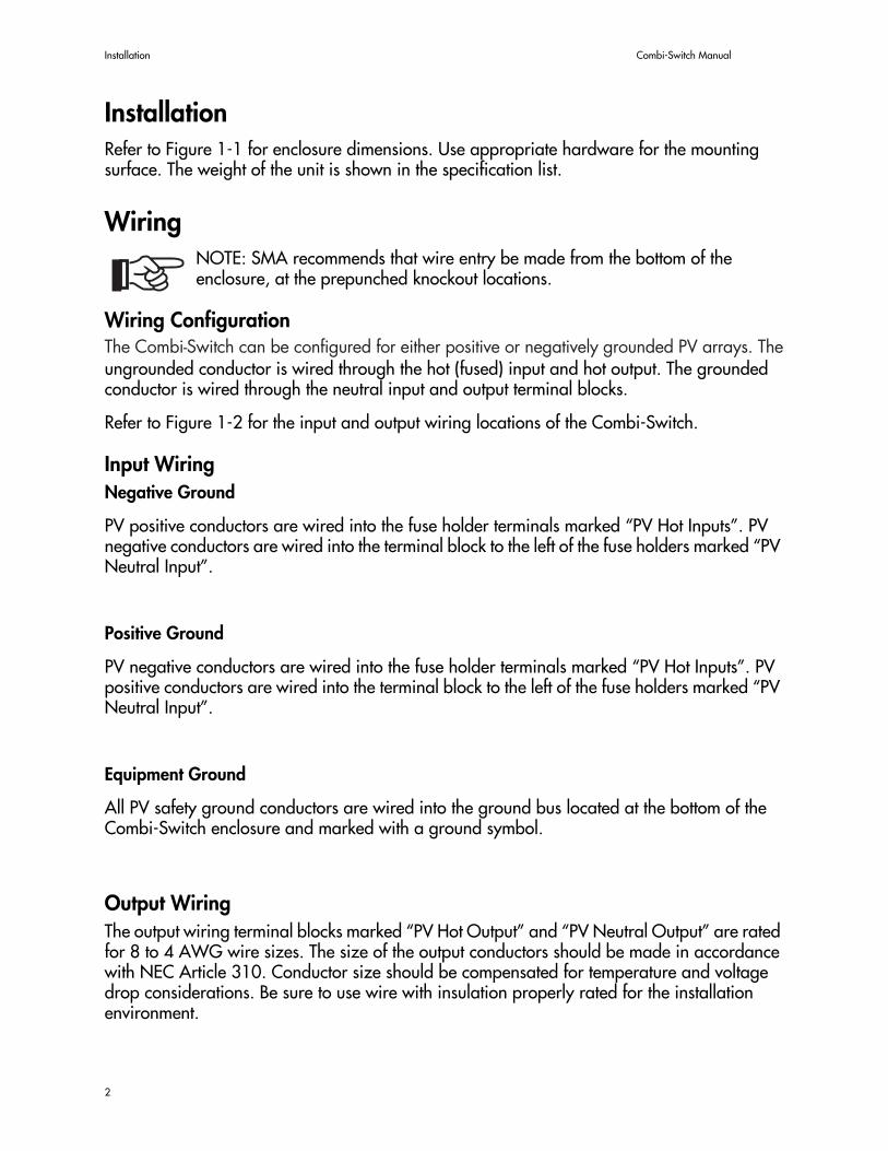
InstallationRefer to Figure 1-1 for enclosure dimensions. Use appropriate hardware for the mounting surface. The weight of the unit is shown in the specification list.
WiringNOTE: SMA recommends that wire entry be made from the bottom of the enclosure, at the prepunched knockout locations.
Wiring ConfigurationThe SBCD can be configured for either positive or negatively grounded PV arrays. The ungrounded conductor is wired through the hot (fused) input and hot output. The grounded conductor is wired through the neutral input and output terminal blocks.
Refer to Figure 1-2 for the input and output wiring locations of the Combi-Switch.
Input WiringNegative Ground
PV positive conductors are wired into the fuse holder terminals marked “PV Hot Inputs”. PV negative conductors are wired into the terminal block to the left of the fuse holders marked “PV Neutral Input”.
Positive Ground
PV negative conductors are wired into the fuse holder terminals marked “PV Hot Inputs”. PV positive conductors are wired into the terminal block to the left of the fuse holders marked “PV Neutral Input”.
Equipment Ground
All PV safety ground conductors are wired into the ground bus located at the bottom of the Combi-Switch enclosure and marked with a ground symbol.
Output WiringThe output wiring terminal blocks marked “PV Hot Output” and “PV Neutral Output” are rated for 8 to 4 AWG wire sizes. The size of the output conductors should be made in accordance with NEC Article 310. Conductor size should be compensated for temperature and voltage drop considerations. Be sure to use wire with insulation properly rated for the installation environment.
2

Combi-Switch Manual Wiring
Figure 1-1 Combi-Switch Schematic and Layout
PV N
EUTRA
L OU
TPUT
PV N
EUTRA
L INPU
T
PV H
OT O
UTPU
T
PV HOT INPUTS
15”
6.625”
1.125”
3

Wiring Combi-Switch Manual
Fuse SizingIn any electrical system, fuses are used to protect wiring and equipment from excessive currents that can cause damage, heating or in extreme cases even fire. If the fuse rating is too small it could open during normal operation. If the fuse rating is too large, it cannot provide the needed protection. In PV systems, the minimum and maximum size of the series fuse is determined by the electrical ratings of the PV module as well as by UL and National Electrical Code (NEC) requirements. Be sure to consult with your PV module manufacturer for appropriate fuse ratings.
The minimum size of fuses and wiring are calculated using the Short Circuit Current Rating (Isc) of the PV module. The NEC requires that all fuses and wiring be sized for a minimum of 1.56 times the Isc of the PV module used in the system.
The proper size PV string fuse is determined by calculating 1.56 x Isc (of the PV module) and then rounding up to the next standard fuse size.
Example: If the Isc of the PV module equals 6.9 Adc, then the fuse size is determined by 1.56 x 6.9 = 10.76. The next standard fuse size would be a 12A, 600Vdc fuse.
DC Disconnect RequirementsNEC 690.15-18 allows the use of fuse holders as a suitable means of disconnecting PV arrays for servicing. Additional DC disconnects external to the inverter may be required by the local authority having jurisdiction.
WARNING: Never open a fuse holder while it is under load. Electrical arcing and damage to the fuse holder will occur if a fuse holder is opened under load.
PV String FusesThe Combi-Switch is shipped with 10A, 600Vdc fuses in the fuse holders. Other fuse sizes are available from SMA America. Be sure to specify alternate fuse sizes when ordering the Combi-Switch from you distributor.
4

Combi-Switch Manual Specifications
Specifications
Number of Inputs 4 Hot and 4 Neutral
Wiring Configuration Positive or Negative Ground
Input Wire Size Positive 14 to 10 AWG
Input Wire Size Negative 14 to 10 AWG
Positive Input Terminal Torque Value 14 in-lb.
Negative Input Terminal Torque Value 35 in-lb.
Max Input Fuse Rating 10 A, 600 VDC, Midget Class
Max Output Current 40 A DC
Max Continuous Output Current 32 A DC
Number of Outputs 1 Hot and 1 Neutral
Output Wire Size Positive 8 to 6 AWG
Output Wire Size Negative 8 to 6 AWG
Output Terminal Torque Values 40 in-lb.
Enclosure Type 3R Rated
Weight 10 lbs. (approx.)
5

Specifications Combi-Switch Manual
6


4031 Alvis CourtRocklin, CA 95677USAPhone +1 916 625 0870Fax +1 916 625 0871www.SMA-America.com
www.SMA-America.com
For product and purchase inquiries contact:
www.ecodirect.com