combivert - endüstriyel otomasyon · the keb combivert f5 series motor control is designed...
TRANSCRIPT
C O M B I V E R T
02/2006
00.F
5.B
UM
-KA
02
Installation Guide & Operation Manual A-Housing1/2 - 1 hp 230 V
B Control
USA

This manual describes the KEB COMBIVERT F5 series motor control. This manual focuses attention on installation, connection as well as basic operation. Due to the various application possibilities and extensive programming capabilities with this unit, it was necessary to provide separet documentation which contains all of this detailed information. Please visit our Web site www.kebamerica.com or contact you local sales office. A list of addtional manuals is provided at the end of this book.
The icons below are used to draw draw attention to the reader. They have the following meanings:
Danger!Warning!Caution!
Attention!Observe atall costs!
InformationHintTip

3
Table of Contents1. Saftey and Operating Instructions ............................................5
2. Product Description ...................................................................6
2.1 Application .......................................................................................6
2.2 Part number identification ................................................................6
2.3 Technical Data .................................................................................72.3.1 230 V-class ..........................................................................................7
2.4 Dimensions and terminals ...............................................................8
3. Installation and Connection ......................................................9
3.1 Control Cabinet Installation .............................................................9
3.2 Good EMC Installation Techniques ................................................10
3.3 Connection of Power Circuit ........................................................ ..113.3.1 Wiring the connectors ..................................................................... ..113.3.2 Wiring instructions ........................................................................... ..113.3.3 Line connection terminal X1.A ...........................................................123.3.4 Motor connection ...............................................................................133.3.5 Motor Overload Protection ................................................................133.3.6 Connection of the braking resistor ................................................. ..14
3.4 Control Circuit: F5-BASIC .............................................................153.4.1 Terminal Strip Connections ...............................................................153.4.2 Connection of the control signals ......................................................153.4.3 Digital Inputs .....................................................................................163.4.4 Analog Inputs ....................................................................................163.4.5 Analog Output ...................................................................................163.4.6 Relay Outputs ...................................................................................16
4. Operation of the inverter..........................................................17
4.1 Digital Operator .............................................................................174.1.1 Keypad ..............................................................................................18
Contents

4
Contents
4.2 Parameter Summary .....................................................................19
4.3 Password Input ..............................................................................20
4.4 Operating Displays ........................................................................20
4.5 Basic Adjustment of the Drive ........................................................22
4.6 Special Adjustments ......................................................................25
4.7 The „Drive Mode“ ...........................................................................374.7.1 Start / Stop Drive ...............................................................................374.7.2 Changing the Direction of Rotation ...................................................374.7.3 Speed setting ....................................................................................374.7.4 Leaving the „Drive Mode“ ............................................................... ..37
5. Error Diagnosis ........................................................................38
6. Quick Reference .......................................................................41

5
1. General
AC motor controls, depending on their degree of protection, may have exposed live, uninsulated, and possibly also moving or rotating parts, as well as hot surfaces.
Removal of the protective covers, improper use, inproper instal-lation or misoperation, can be dangerous and result in serious personal injury and or damage to property.
This document must be read in its entirety before attemping to apply votlage to the KEB COMBIVERT F5.
All functions of, installation and commissioning as well as maintenance are to be carried out by skilled or certified technical personnel (Observe IEC 364 or CENELEC HD 384 or DIN VDE 0100 and IEC 664 or DIN/VDE 0110, NEC and all national and local codes and accident prevention rules!).
For the purposes of these basic safety instructions, ”skilled techni-cal personnel“ means persons who are familiar with the installation, mounting, commissioning and operation of the product and have the qualifications needed for the performance of their functions.
2. Intended use
AC motor controls are components designed for installation and operation in electrical installations or machinery.
In case of installation in machinery, commissioning of the drive converter (i.e. the starting of normal operation) is prohibited until the machinery has been proved to conform to the provisions of the directive 89/392/EEC (Machinery Safety Directive - MSD). Account is to be taken of EN 60204.
Commissioning (i.e. the starting of normal opertion) is admissible only where conformity with the EMC directive (89/336/EEC) has been established. The KEB COMBIVERT F5 motor controls meet the requirements of the low-voltage directive 73/23/EEC. They are subject to the harmonized standards of the series DIN EN 50178/ VDE 0160 in conjunction with EN 60439-1/ VDE 0660, part 500, and EN 60146/ VDE 0558.
The technical data as well as information concerning the sup-ply conditions shall be taken from the name plate and from the documentation and shall be strictly observed.
3. Transport, storage
The instructions for transport, storage and proper use shall be complied with.
The climatic conditions shall be in conformity with EN 50178.
Safety and operating instructions forAC motor controls
(in conformity with the low-voltage directive 73/23/EEC)
Important, please read
1. Saftey and Operating Instructions
4. Installation
The installation and cooling of the unit shall be in accordance with the specifications contained with in this document.
The unit shall be protected against excessive force or strain. In particular, no components must be bent or isolating distances altered in the course of transportation or handling. No contact shall be made with electronic components and contacts.
Drive converters contain electrostatic sensitive components which are can be damaged through improper use or handling. Electric components must not be mechanically damaged or destroyed (potential health risks).
5. Electrical connection
RISK OF ELECTRIC SHOCK! Allways disconnect the supply volt-age before installing or servicing the KEB COMIBIVERT F5 motor control! Wait five minutes for the before attempting to change any connections as the internal DC bus must first dicharge.
If it is necessary to work with the voltage supply turned on, always comply with the applicable national accident prevention rules (ex O.S.H.A.).
The electrical installation shall be carried out in accordance with the relevant requirements (NEC and local codes). For further information, see documentation.
Instructions for installation in accordance with EMC requirements, like sheilding, grounding, location of filters and wiring, are inculded in the documentation. They must always be complied with. Mo-tor controls bearing a CE marking do not preclude adherence to proper EMC installation requirements. Observance of the allowed values required by EMC law is the responsibility of the designer or manufacturer of the installation or machine.
6. Operation
Installations which include motor controls shall be equipped with additional control and protective devices in accordance with the relevant applicable safety requirements. Changes to the motor control by means of the operating software are admissible.
After disconnection of the motor control from the supply voltage, live parts and power terminals must not be touched because DC BUS capacitors may still be energized. Alwyas follow the printed warnings on the unit.
During operation, all covers and doors shall be kept closed.
7. Maintenance and servicing
The manufacturer’s documentation shall be followed.
KEEP SAFETY INSTRUCTIONS IN A SAFE PLACE!

6
Cooling1) 0: Standard
Interface type1)
0: none
Rated switching frequency1)
8 - 2 kHz9 - 4 kHzA - 8 kHz
Input identificationK: 230 VAC or 325 VDC
P/R/S/T1) Special or customer specification
Housing type A
Accessory0: None 3: Braking transistor and integrated EMI filter
Control typeB: BASIC
Series F5
Inverter size
Product Description
2. Product Description 2.1 Application
The KEB COMBIVERT F5 series motor control is designed exclusively for the control and regulation of induction motors. The operation of other electric devices and loads is prohibited and can lead to the destruction of the unit. The F5 series motor control is a component which is intended for the installation in elecric systems or machines.
2.2 Part number identification 07.F5.B0A–K900
1) For special untis the last three digits are custom defined

7
2.3 Technical Data 2.3.1 230 V-class
Product Description
Inverter Size 05 07Recommended Motor Power [hp] 1/2 1Housing size A AInput Ratings
Supply voltage [V] 180...260 ±0 (230 V rated voltage)Supply voltage frequency [Hz] 50 / 60 +/- 2
Input phases 1 1Rated input current [A] 4,6 8
Maximum input fuse [A] 10 15Recommended wire gauge [awg] 14 14
Output RatingsRated output power [kVA] 0,9 1.6Rated motor power [kW] 0.37 0.75
Rated output current [A] 2.3 4.0Peak current (30 seconds) [A] 4,1 7.2
Over current fault (E.OC) trip level [A] 5.0 8.6Overload curve (see annex) 1
Output voltage [V] 3 x 0...V inputOutput frequency [Hz] 0…400Hz
Rated switching frequency [kHz] 4 8Maximum switching frequency [kHz] 8 8Power loss at rated operation1) [W] 30 60
Stall current at 4kHz [A] 2.3 4Stall current at 8kHz [A] 2.3 4
Stall current at 16kHz [A] – –Braking Circuit
Min. braking resistance 2) [Ω] 100 100Typ. braking resistance 2) [Ω] 180 100
Max. braking current [A] 4.5 4.5Installation Information
Max. shielded motor cable length at 4 kHz 3) [ft] 30 30Max. shielded motor cable length at 8 kHz 3) [ft] 30 30Max. shielded motor cable length at 16kHz3) [ft] – –
Tightening torque for terminal strip [in lb] Not applicableEnvironmental
Max. heat sink temperature TOH [°C] 100°C / 212 °F 95°C / 203°FStorage temperature [°C] -25...70 °C / -13…158°F
Operating temperature [°C] -10...45 °C / 14…113°F Housing design / protection Chassis / IP20
Relative humidity max. 95% without condensationApprovals
Tested in accordance with… EN 61800-3 /UL508CStandards for emitted interference EN 55011 Class B / EN 55022 Class A
Standards for noise immunity IEC 1000-4-2 / -3 / -4 / -5/ -6Climatic category 3K3 in accordance with EN 50178
1) Rated operation means rated switching frequency, rated voltage, and rated output current.2) Only for units with the braking circuit installed.3) Maximum cable length is based on the the use of shield motor cables, ground current limitations, EMI levels
set forth in EN55011. Contact KEB for more information.

8
2.4 Dimensions and terminals
Pay attention to the input voltage, since both 230 V and 460 V units (3-phase) are pos-sible.
X1A Connection from the lineX1B Connection to the motor, brake resistor, temp sensorX2A Connectin for control cablesX4A Connection for Operator/display HSP5-Servicecable Connection for shield / ground
Weight 1/2 kg / 1 lb
Product Description

9
Installation and Connection
3. Installation and Connection 3.1 Control Cabinet Installation
Enclosure type: IP20 / Open TypeOperation temperature: -10...45°C / 14...113°FStorage temperature: -25...70°C / -13...158°Fmax. heat sink temperature: Size 05/230 V 100°C / 212°FSize 07/230 V 95°C / 203°FClimatic category: 3K3 in accordance with EN 50178Relative humidity: max. 95 % without condensationPower derating for high altitude: 1 % for every 100 m/330 ft above 1000 m/3300 ft Maximum altitude for operation: 2000 m / 6,600 ft
Installation requirements:• Mount in a stationary location with low vibration. Contact KEB
when mounting on a moving system.• Adhere to minimum clearance distances in diagram 3.1. Mul-
tiple units can be mounted side by side with zero clearance.• Most units have forced airflow from bottom to top using a ther-
mostatically controlled variable speed fan. Leave space above and below the unit for proper air flow.
• Prevent dust or debries from entering the unit, especially during the construction of the con-trol panel. Metal chips can cause internal shorts or malfunctions.
• Installation in a sealed enclosure requires proper cooling, be sure to over size control cabinet or provide suitable cooling device.
• Protect the unit against conductive and corrsive gases and liquids. • Water, mist, or steam should not be allowed into the unit.• Do not allow water to condence within the unit • The COMBIVERT F5 must not be installed in and “Explosion Proof” environment.
ANTRIEBSTECHNIK
ANTRIEBSTECHNIK
Dia. 3.1

10
3.2 Good EMC Installation Techniques
1) Mount the COMBIVERT F5 on a conductive (zinc or nickel plated not painted) sub plate. This sub plate serves as the central grounding point for the machine.
2) Always connect the shield of motor and control cables with maximum surface area, use metal cable clamp to contact cable shield on all sides. Using a single strand of the shield or the drain wire form the shield as the only connection can reduce the shield’s effectiveness by 70%.
3) The distance between control and power cables should be at least 10..20 cm / 4...8 inches.
4) Keep the motor and power cable spacially separated especially if running parallel.
5) If it cannot be avoided, cross control and power cables and motor cables at a right angle.
6) Install all cables as close as possible to the mounting plate - ideally in a metal wireway.
7) Ridged metal conduit can be used as a shield for the motor cables. Always observe the following points: • Remove all paint from the control panel where the conduit is to be secured.
• Securely fasten all conduit fittings. • Run only the motor wires through the conduit. All other wires must be pulled through a separete conduit. • Connect the control panel to the sub panel with a heavy ground strap.
8) If a KEB EMI (CE) filter is used, it must be mounted as close as possible and to the same subpanel as the COMBIVERT F5 motor control. The filter must have large bare surface contact with the subpanel. Use only the wires from the filter to connect to the inverter. Never add additional lengths of wire.
9) All ground connections should be as short as possible. Always avoid creating ground loops. NEC requires a ground conductor connected to every COMBIVERT F5 controller inspite of the metal on metal connection to the subplate.
You can find further instructions regarding EMC and proper wiring considerations by contacting KEB technical support or visiting the website www.kebamerica.de.
Installation and Connection

11
Installation and Connection
3.3 Connection of Power Circuit 3.3.1 Wiring the connectors
RISK OF ELECTRIC SHOCK! Always disconnect supply voltage before servicing the COMBIVERT F5. Wait 5 minutes before attempting to change the connections as the DC Bus capacitors may still be charged. Absolutely pay attention to the nameplate voltage of the KEB COMBIVERT and the connected line voltage. A 230V-unit will be immediately destroyed on a 460V-power supply. Never exchange the line and motor cables. The unit will be destroyed.
The COMBIVERT F5 motor controls specified in this manual are suitable for use on a circuit capable of delivering not more than 10kA rms symmetrical ampers at the rated maximum voltage.Connection of the F5 series motor control to voltage systems configured as corner grounded delta, center tap grounded delta, open delta, or ungrounded delta may defeat the internal noise suppression. With this type of voltage supply the maximum phase to ground votlage is 300VAC for 230 VACrms units. A balanced, center ground wye connection is always recommended. The three phase voltage imbalance must be less than 2% phase to phase. Greater imbalance can lead to destruction of the unit.
3.3.2 Wiring instructions
7
L1L2L3++--
E
Steps to wire the connectors • Remove the connector from the inverter housing by
grasping it firmly and pulling straight out• The maximum wire gauge is 14 awg or 1.5mm• Strip the insulation back 0.25 in (7mm)• The use of ferrules is optional• Press a flathead screwdriver into the upper
slot• Slide the bare wire into the lower slot• Remove the screw driver and check the
wire connection by pulling back on the wire to ensure it stays

12
Installation and Connection
3.3.3 Line connection terminal X1.A
DC-connection 230 V-class
250...370 V DC
For branch circuit protection use fuses rated for DC voltage. (Bussmann type FWP)
Line connection 230 V 3-phase
Line connection 230 V 1-phase
PEL1N/L2L3
++--
Terminal strip X1A Provides connections for: • 230 V AC / 1-phase (L1/L2) • 230 V AC / 3-phase (L1, L2, L3) • DC-Supply 250...370 V DC (++, --)
• Always note the rated voltage, select the appropriate over current protection devices, select a disconnect device, and select the proper wire size before begining the wiring process. Wire the COMBIVERT F5 according to NEC Class 1 requirements.
• Always use UL listed or CSA approved copper wire with a minimum temperature rating of 75°C. The wire gauge listed in the tables in section 2.3 is based on the maximum fuse rating, copper wire and a 75°C insulation rating (THHW or equivilant). If a lower level of overcurrent protection is used, it may be possible to reduce the size of the wire. Use 300V rated wire for 230V systems .
• A disconnect switch or contactor shall be provided as a means of turning off the supply voltage. Repetitive cycling on and off of the supply votlage more than once every 5 minutes can lead to damge of the unit.
• Class CC (Bussmann type LP-CC or equivilant) fuses or a circuit breaker with type D trip characteristic must be used to provide branch circuit protection of the COMBIVERT F5. The voltage rating of the fuse or circuit breaker shall be at least 250V for 230V units. See table in section 2.3 for over current protection amperage ratings.
• Power connection must be installed as indicated on the previous page. Always be sure to double check power connections for tightness.
• For installation requiring line side ground fault protection (GFI) consult KEB.• Line chokes can be used to reduce harmonics, conducted high frequency noise, and can
extend the lifetime of the unit. Consult KEB for more information.

13
3.3.5 Motor Overload Protection The COMBIVERT F5 motor control by default provides motor overload protection at 130% of the unit’s rated output current. See tables in section 2.3 for rated output current. Two additional motor overload protection systems are avaialble. Electronic Motor Overload ProtectionThis software function provides speed dependent I2t overload protection and is approaved by UL as a solid state overload protection device according to UL508C section 42 and NEC 430 Part C. The trip current is adjustable as well as whether the motor is self cooled or blower cooled. Consult the F5B/G Application instruction manual for adjustment details. Motor Winding Temperature Sensor• Connects to Terminals T1, T2• Trip resistance level 1.65...4 kΩ• Reset resistance level 0.75...1.65 kΩ• This function can be activated or deactivated through a software parameter. The default setting
is OFF!• Do not run temperature sensor wires in the same conduit or wire way as other control cables.
These sensor wires most likely are carrying high frequency noise from the motor. • If the sensor wires are part of the motor cable they must be shielded independently from the
motor wires.
Installation and Connection
3.3.4 Motor connection
The maximum m o t o r c a b l e length listed in
the tables in section 2.3 is based on several factors: use of shielded motor cables, ground current l imitat ions, increased EMI noise levels, voltage peaks at the motor terminals.
Connect shield to the mounting plate with maximum surface area
(use metal cable clamp)
Terminal X1B provides connections for:• ++, PB Braking resistor• U, V, W Motor• T1, T2 Temperature sensor
T2T1PB
PAWVU
PE
Terminal strip X1A Provides connections for: • 230 V AC / 1-phase (L1/L2) • 230 V AC / 3-phase (L1, L2, L3) • DC-Supply 250...370 V DC (++, --)

14
Installation and Connection
3.3.6 Connection of the braking resistor
Braking resistors can develop very high surface temperatures, therefore install away from other devices, above the motor control and where people can not inadvertantly come in contact with it.
Braking resistor connection with high temperature drive fault• The resistor has a PTC type sensor and is connected to the T1, T2
terminal on the COMBIVERT F5. If a motor temperature sensor is used it should be placed in series with the sensor of the braking resistor. Note: if the braking transistor in the unit fails, there is no guarantee the voltage to the resistor will be shut off!
Typical braking resistors for A housing COMBIVERT F5 motor controls F5 Size 230V Class Ohms PD P6 05 07.BR.100-1180 180 44 800 07 07.BR.100-1180 180 44 800 PD = continuous power disapation in watts, P6 = peak repetitive power disapation with a 6 sec on time and 120 sec cycle time. KEB can offer many types of braking resistors, please contact your sale representative for more information.

15
In order to prevent a malfunction caused by interference voltage on the control inputs, the following steps should be observed:
• Establish a common ground point for all ground connec-tions.
• Use shielded cable with twisted pair wires.• Terminate shield wires to earth ground, only at inverter.• Separate control and power wires 8" or more apart.• Control and power wires to cross at a right angle.
PIN Function Name Description
1 + Analog input 1 AN1 Voltage input for speed resolution: 11 Bit, 0...±10 VDC
^ 0...±CP.11, scan time: 2 ms
5 Analog output 1 ANOUT1 Analog output of the actual voltage range: 0...±10 VDC output frequency ^ 0...±100 Hz, Rout = 100 kΩ,
resolution: 12bit
7 +10V Output CRF Analog supply voltage for speed ref. +10 VDC +5%, max. 4 mA
8 Analog Common COM Common for analog In- and Outputs
10 Fixed frequency 1 I 1 I1 + I2 = Fixed frequency 3;
11 Fixed frequency 2 I 2 no input = analog voltage (speed) ref.
14 Forward F Preset rotation; Ri = 2.1 k Ohm
15 Reverse R Forward has priority scan time: 2 ms
16 Control release, Reset ST Inverter enable, disable;
Error Reset at opening
20 24V-Output Vout Approx. 24V Output (max.100 mA)
22 Digital Common 0V Common for digital In-/Outputs
24 Relay 1, NO contact RLA Relay output;
25 Relay 1, NC contact RLB fault relay(default);
26 Relay 1, switching cont. RLC Function can be changed with CP.31; max. 30 V DC, 1 A
27 Relay 2, NO contact FLA Relay output;
28 Relay , NC contact FLB frequency dependent switch (default);
29 Relay 2, switching cont. FLC Function can be changed with CP.32; max. 30 V DC, 1 A
Installation and Connection
3.4.2 Connection of the control signals
1 5 7 8 10 11 14 15 16 20 22 24 25 26 27 28 29
X2A
3.4.1 Terminal Strip Connections 3.4 Control Circuit: F5-BASIC
EMC

16
Installation and Connection
Internal analogspeed ref. setting
External analogspeed ref. setting
3.4.5 Analog Output
3.4.4 Analog Inputs
3.4.3 Digital Inputs
In case of inductive load on the relay output, protective wiring must be provided (e.g. free-wheeling diode)!
3.4.6 Relay Outputs
Rin = 2.1 kΩ
Use of external voltage supply
Use of internal voltage supply
20...30 VDC Regulated

17
As an accessory for displaying and editing "CP" parameter values, a "digital operator" is necessary. To remotely mount the digital operator, a operator remote cable is required (option: cable 00.F5.0C0-1xxx). To prevent malfunctions, the inverter must be brought into nOP status (remove signal from control release terminal 16) before connecting/ disconnecting the operator. When starting the inverter without an operator, it is started with the last stored values.
4. Operation of the inverter
Operation of the Drive
4.1 Digital Operator
Only use the operator interface for the serial data transfer to RS232, 485. The direct connection from PC to the inverter is only valid with a special cable (HSP5 Part No. 00.F5.0C0-0001), oth-erwise it will lead to the destruction of the PC-interface!
Standard Operator: Part No. 00.F5.060-1000Serial Operator: Part No. 00.F5.060-2000
5 4 3 2 1
9 8 7 6
ANTRIEBSTECHNIK
START
STOP
FUNC.
SPEED
ENTER
F/R
Double function keypad
Operating-Error displayNormal "LED on"Error "LED blinks"
5-digit LED Display
Serial CommunicationTransmit "LED on"(Ref.: 00.F5.060-2000)
RS232, RS485 (Ref.: 00.F5.060-2000)
PIN RS485 Signal Meaning 1 – – reserved 2 – TxD Transmitter signal, RS232 3 – RxD Receiver signal, RS232 4 A' RxD-A Receiver signal A, RS485 5 B' RxD-B Receiver signal B, RS485 6 – VP Voltage supply-Plus +5V (Imax = 10 mA)
7 C, C' DGND Data reference potential 8 A TxD-A Transmitter signal A, RS485 9 B TxD-B Transmitter signal B, RS485

18
When switching on the KEB COMBIVERT F5, the value of parameter CP.1 appears in the operator display. (see "Drive Mode" to switch the keypad function)
The function key (FUNC) changes be-tween the parameter value and parameter number.
With UP and DOWN, the value of the pa-rameter number is increased/decreased.
Generally; when a value is changed, parameter values are immediately accepted and stored nonvolatile. However, with some parameters it is not useful that the adjusted value is accepted immediately. In these cases (CP.17, CP.18, CP.22, CP.26, CP.29, CP.31, CP.32, CP.34, CP.35) the adjusted value is accepted an stored nonvolatile by pressing ENTER.
If a drive fault occurs during operation, the display changes to the drive fault message. The drive fault message in the display is cleared by press-ing ENTER.
Operation of the Drive
4.1.1 Keypad
Pressing ENTER only clears the fault message in the display. In the Inverter status display (CP. 3), the fault is still displayed until the inverter has been reset. In order to reset the fault itself the cause must be identified and removed, than a reset signal applied to terminal 17 terminal 16, F5-Basic or a power-on reset (cycle supply voltage off and then on) must occur.
FUNC.
SPEED
START
STOP
START
STOP
ENTER
F/R
error
19
Operation of the Drive
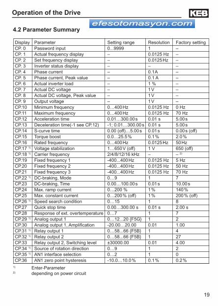
4.2 Parameter Summary
1) Enter-Parameter2) depending on power circuit
Display Parameter Setting range Resolution Factory settingCP. 0 Password input 0...9999 1 –CP. 1 Actual frequency display – 0.0125 Hz –CP. 2 Set frequency display – 0.0125 Hz –CP. 3 Inverter status display – – –CP. 4 Phase current – 0.1 A –CP. 5 Phase current, Peak value – 0.1 A –CP. 6 Actual inverter load – 1 % –CP. 7 Actual DC voltage – 1 V –CP. 8 Actual DC voltage, Peak value – 1 V –CP. 9 Output voltage – 1 V –CP.10 Minimum frequency 0…400 Hz 0.0125 Hz 0 HzCP.11 Maximum frequency 0…400 Hz 0.0125 Hz 70 HzCP.12 Acceleration time 0.01…300.00 s 0.01 s 5.00 sCP.13 Deceleration time(-1 see CP.12) -1; 0.01…300.00 s 0.01 s 5.00 sCP.14 S-curve time 0.00 (off)…5.00 s 0.01 s 0.00 s (off)CP.15 Torque boost 0.0…25.5 % 0.1 % 2.0 %CP.16 Rated frequency 0…400 Hz 0.0125 Hz 50 HzCP.17 1) Voltage stabilization 1…650 V (off) 1 V 650 (off)CP.18 1) Carrier frequency 2/4/8/12/16 kHz – – 2)
CP.19 Fixed frequency 1 -400...400 Hz 0.0125 Hz 5 HzCP.20 Fixed frequency 2 -400...400 Hz 0.0125 Hz 50 HzCP.21 Fixed frequency 3 -400...400 Hz 0.0125 Hz 70 HzCP.22 1) DC-braking, Mode 0…9 1 7CP.23 DC-braking, Time 0.00…100.00 s 0.01 s 10.00 sCP.24 Max. ramp current 0…200 % 1 % 140 %CP.25 Max. constant current 0…200 % (off) 1 % 200 % (off)CP.26 1) Speed search condition 0…15 1 8CP.27 Quick stop time 0.00…300.00 s 0.01 s 2.00 sCP.28 Response of ext. overtemperature 0…7 1 7CP.29 1) Analog output 1 0…12...20 F5G 1 2CP.30 Analog output 1, Amplification -20.00…20.00 0.01 1.00CP.31 1) Relay output 1 0…58...66 F5B 1 4CP.32 1) Relay output 2 0…58...66 F5B 1 27CP.33 Relay output 2, Switching level ±30000.00 0.01 4.00CP.34 1) Source of rotation direction 0…9 1 2CP.35 1) AN1 interface selection 0…2 1 0CP.36 AN1 zero point hysteresis -10.0…10.0 % 0.1 % 0.2 %

20
The parameters below provide the user with the ability to monitor various operating characteristics of the drive. These parameters are very useful during commissioning and trouble shooting.
Display of the actual output frequency with a resolution of 0.0125 Hz. The digital operator will display "noP" or "LS" if the enable (terminal 16) or the direction of rotation (terminal 14 or 15) are not energized (see CP.3). The rotation of the motor is indicated by the sign.
Output frequency 18.3 Hz, rotation forwardExamples: Output frequency 18.3 Hz, rotation reverse
4.4 Operating Displays
Actual frequency display
Inverter status display
The status display shows the actual working conditions of the inverter. Possible displays and their meanings are:
"no Operation" control release (terminal 16) signal removed, modulation off, output voltage = 0 V, drive is disabled.
" Low Speed " no direction signal at F or R (terminal 14 or 15), modulation off, output voltage = 0 V.
Display of the actual set frequency. The indication is done in the same manner as at CP.1. For control reasons the set frequency is displayed even if control release or direction of rotation are enable. If no direction of rotation is set, the set frequency for clockwise rotation (forward) is displayed.
Set frequency
Operation of the Drive
4.3 Password Input
FUNC.
SPEED
START
FUNC.
SPEED
ENTER
F/R
FUNC.
SPEED
START
FUNC.
SPEED
ENTER
F/R
Releasing the CP-Parameters
Locking the CP-Parameters(Read only)
From the factory, the frequency inverter is supplied without pass-word protection, this means that all parameters can be adjusted. After programming, the unit can be protected against unauthorized access thus preventing the values from being changed.

21
V-class Normal operation Over volt. (E.OP) Under volt. (E.UP) 230 V 290…330 V DC approx. 400 V DC approx. 216 V DC 460 V 530…700 V DC approx. 800 V DC approx. 240 V DC
"Forward Acceleration" drive accelerates with direction of rota-tion forward .
"Forward Deceleration" drive decelerates with direction of rotation forward.
"Reverse Acceleration" drive accelerates with direction of rota-tion reverse.
"Reverse Deceleration" drive decelerates with direction of rotation reverse.
"Forward Constant" drive runs with a constant speed and direc-tion of rotation forward.
"Reverse Constant" drive runs with constant speed and direction of rotation reverse.
Other status messages; such as error(E.xxx) and malfunction (A.xx) codes, are described towards the end of this manual.
Operation of the Drive
Phase current Display of the actual real-time phase current in ampere, (see also CP.5).
DC bus voltage Display of actual DC voltage in volts.Typical values:
CP.5 makes it possible to display the peak current within an operating cycle. The highest value of CP.4 is stored in CP.5. The peak value in memory can be cleared by pressing the" UP, DOWN or ENTER" key or by writing via serial communication any value you like to the address of CP.5. Switching off the inverter also clears the memory.
Phase current /Peak value
Actual inverter load Display of the actual inverter loading in percent. 100% rate of utilization is equal to the inverter rated current. Only positive values are displayed, meaning there is no differentiation between motor and regenerative operation.

22
This display makes it possible to recognize instantaneous voltage peaks within an operating cycle. The highest value of CP.7 is stored in CP.8.
The peak value in memory can be cleared by pressing the UP, DOWN or ENTER key or by writing any value you like to the address of CP.8. Switching off of the inverter also clears the peak value.
Display of the actual output voltage in volts rms.
4.5 Basic Ad-justment of the Drive
Actual DC voltage peak value
Output voltage
Minimum frequency
Maximum fre-quency
Operation of the Drive
The following parameters determine the fundamental operating data of the drive. They should be checked and/or adjusted for the application.The frequency the inverter outputs with 0V applied to the analog input or if
the activated fixed frequency (CP.19…CP.21) is lower than this value.
Adjustment range: 0...400 HzResolution: 0.0125 HzFactory setting: 0.0 Hz
The frequency the inverter outputs with 10V ap-plied to the analog input or if the activated fixed frequency (CP.19…CP.21) is greater than this value.
Adjustment range: 0...400 HzResolution: 0.0125 HzFactory setting: 70 Hz

23
The parameter determines the time needed to accelerate from 0 Hz to 100 Hz. The actual acceleration time is proportional to the frequency change. 100 Hz –––––– x actual acceleration time = CP.12 delta f
Adjustment range: 0.01...300.00 sResolution: 0.01 sFactory setting: 5.00 s
Example: actual acceleration time = 5s; the drive should accelerate from 10 Hz to 60 Hz, delta f = 60 Hz - 10 Hz = 50 Hz
CP.12 = (100 Hz / 50 Hz) x 5 s = 10 s
The parameter determines the time needed to decelerate from 100 Hz to 0 Hz. The actual deceleration time is proportional to the frequency change.
100 Hz –––––– x actual deceleration time = CP.13 delta f
Adjustment range: -1; 0.01...300.00 sResolution: 0.01 sFactory setting: 5.00 s
By depressing DOWN arrow key, one increment passed the 0.0, the display will show "=Acc". This means the same value stored in CP.12 (Decel=Accel time)!
Example: actual deceleration time = 5s; the drive should decelerate from 60 Hz to 10 Hz. delta f = 60 Hz - 10 Hz = 50 Hz
CP.13 = (100 Hz / 50 Hz) x 5 s = 10 s
For some applications it is advantageous when the drive starts and stops jerk-free. This is achieved by modifying the acceleration and deceleration ramps. This modification time; also called S-curve time, can be adjusted with CP.14.
Adjustment range: 0.00 (off)...5.00 sResolution: 0.01 sFactory setting: 0.00 s (off)
Basic Adjustment of the Drive
Acceleration time
Deceleration time
S-curve time
In order to define the ramps with the activated S-curve time, the acceleration and deceleration times (CP.12 and CP.13) must be adjusted higher than the S-curve time (CP.14).
100 Hz
CP. 12
f
t
100 Hz
CP. 13
f
t
24
Basic Adjustment of the Drive
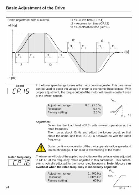
Boost
t1 t1 t1 t1
t2 t3
+f [Hz]
-f [Hz]
t [s]
t1 = S-curve time (CP.14)t2 = Acceleration time (CP.12)t3 = Deceleration time (CP.13)
t1t1
t2 t3
Ramp adjustment with S-curves
The inverter will output the applied input voltage or the voltage value adjusted in CP.17 at the frequency value adjusted in this parameter. This param-eter is typically adjusted for the motor rated frequency. Note: Motors can overheat when the rated frequency is incorrectly adjusted!
Adjustment range: 0...400 HzResolution: 0.0125 HzFactory setting: 60 Hz
Rated frequency
t1t1
In the lower speed range losses in the motor become greater. This parameter can be used to boost the voltage in order to overcome these losses. With proper adjustment, the torque output of the motor will remain constant even at the lowest speeds.
Adjustment range: 0.0...25.5 %Resolution: 0.1 %Factory setting: 2.0 %
Adjustment:Determine the load level (CP.6) with no-load operation at the rated frequency.Then run at about 10 Hz and adjust the torque boost, so that about the same load level (CP.6) is achieved as with the rated frequency.
During continuous operation; if the motor operates at low speed and too much voltage, it can lead to overheating of the motor.

25
Basic Adjustment of the Drive
4.6 Special Adjustments The following parameters serve for the optimization of the drive and the adaptation to certain applications. These adjustments can be ignored at initial start-up.
This parameter can be used to regulate the output voltage in relation to the rated frequency. With this function active, voltage variations at the input as well as on the DC bus will have only a small influence on the output voltage (V/Hz-characteristic). This function can be used to adapt the output voltage for special motors and can also prevent damage to the motor resulting from over or under voltage supply.
Adjustment range: 1...650 V (off)Resolution: 1 VFactory setting: 650 V (off)Note: Enter-Parameter
In the example below using a motor rated at 230 V / 60Hz, the output voltage is too high due to our supply being 250 V and CP.17 off. By setting CP.17 to the correct rated motor voltage of 230 V, the voltage is clamped thereby giving the motor the correct voltage.
If the supply voltage drops to190 V and CP.17=230 V, the inverter will still provide rated voltage to the motor up until 190V. The output voltage can not be increased further beyond the input therefore the motor will operate in field weakening. To calculate at which frequency this will occur use the following formula: f = (60Hz/ 230 V)*190 V= 50 Hz CP.17 = 230V Vsupply = 190V
* Both scenarios above, it is assumed no boost (CP.15=0%).
Voltage stabilization
VO at VI = 250V stabilized
VO at VI = 250V not stabilized
VO at VI = 190V stabilized
VO at VI = 190V not stabilized
VI = input voltageVo=output voltage

26
Fixed frequencies 1...3
Input I1
Input I2
Input I1 and I2
Three fixed frequencies can be adjusted. The fixed frequencies are selected with the inputs I1 (terminal 10), I2 (terminal 11) and I1 + I2.
Adjustment range: -400...400 HzResolution: 0.0125 HzFactory setting, CP.19: 5 HzFactory setting, CP.20: 50 HzFactory setting, CP.21: 70 Hz
If the adjusted values are outside of the fixed limits of CP.10 and CP.11, then the actual run frequency is internally limited to the values of CP.10 and CP.11. The negative rotation values (i.e. -50Hz) are only available in the "application mode". The rotation source of the fixed frequencies is not changed by CP.34, it always corresponds to CP.34 = 2 (Fwd/Rev direction selectable by terminal 14 or 15).
Adjustment range : 2/4/8/12/16 kHzResolution: 1Factory setting: _ (depending on power circuit) Note: Enter-Parameter
Low Switching Frequency Lower inverter heating Lower High Freq. ground current Reduced power lossLower radio interferences Reduced cogging at low speed
High Switching FrequencyLess audible noise producedImproved sine-wave simulationLess motor losses
Carrier frequency The frequency with which the power modules are switched can be changed depending on the application. The employed power stage determines the maximum switching frequency as well as the factory setting. Generally, the inverter can operate at frequencies higher than the rated value but not under continuous load.
Special Adjustments
At switching frequencies above 4 kHz pay absolute attention to the max. motor cable length especially when using shielded cables.

27
DC-braking Mode
Special Adjustments
If the braking time depends on the actual frequency (CP.22 = 2...7), it is calculated as follows:
CP.23 x freal tBrake = ––––––––– 100 Hz
Otherwise the braking time corresponds to CP.23.
Adjustment range: 0.00...100.00 sResolution: 0.01 sFactory setting: 10.00 s
DC-braking Timef
t
100 Hz
factual
tBrake CP.23
During DC-braking, the motor is not decelerated by a controlled ramp. Quick braking without regen voltage can be achieved by applying a DC voltage to the motor winding. Parameter values listed below, determine how the DC-braking is triggered.
Value DC-Braking Activation 0 Deactivated 1 Activates when direction signal is removed and the output frequency
has reached 0Hz. The braking time is dependent on CP.23 or until the next direction of rotation.
2* Activates as soon as the direction signal is removed. 3* Activates as soon as the direction signal is removed or
changed. 4* Activates as soon as the direction signal is removed and if the
real frequency goes below 4 Hz. 5* Activates when the real frequency goes below 4 Hz. 6* Activates as soon as the set value goes below 4 Hz. 7* Activates when input I4(terminal 13) is switched. 8 Activates as long as input I4 is switched. 9 Activates before the acceleration ramp when a direction signal is
given. The time is dependent on CP.23.
* Braking time depends on the actual frequency.
Adjustment range: 0...9Resolution: 1Factory setting: 7 Note: Enter-Parameter

28
This function acts as an adjustable current limit when operating at a con-stant speed. It can be used to prevent the load current from exceeding the inverter's over current level, thereby preventing shut down of the inverter with an E.OC fault. When the load level reaches the adjusted value, the output frequency is reduced until the load drops below the adjusted value, after which the frequency is increased again to the previous value. Setting the value too low may prevent the motor from running at the desired speed. CP. 3 displays "SSL" when the function is active.
Adjustment range: 0...200 % (off)Resolution: 1 %Factory Setting: 200 % (off)
t
fset
factual
on
off
on
off
CP.25
CP.24
LAD-stop
Current limit
t
t
t
Max. constant current
Utilization
This function acts as an adjustable current limit during acceleration or deceleration. It can be used to prevent the load current from exceeding the inverter's peak current rating, thereby preventing shut down with an E.OC fault. When the load level reaches the adjusted value, the acceleration or deceleration is stopped until the load drops below the adjusted value. Note: if this parameter is adjusted too low, the motor may not be able to accelerate to full speed. The motor will run at a low speed. CP.3 displays "LAS" when the function is active.
Adjustment range: 0...200 %Resolution: 1 %Factory setting: 140 %
Max. ramp current
Special Adjustments
29
Special Adjustments
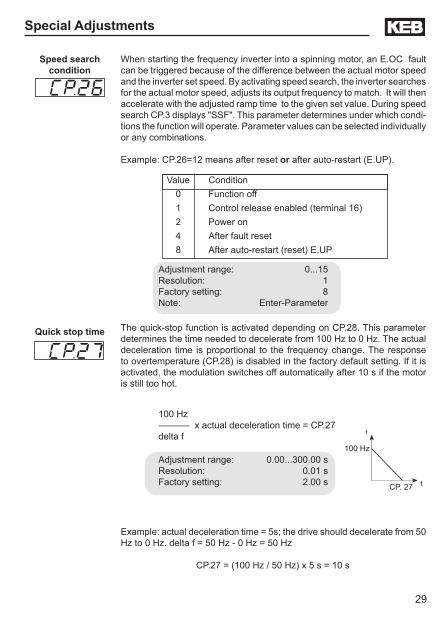
When starting the frequency inverter into a spinning motor, an E.OC fault can be triggered because of the difference between the actual motor speed and the inverter set speed. By activating speed search, the inverter searches for the actual motor speed, adjusts its output frequency to match. It will then accelerate with the adjusted ramp time to the given set value. During speed search CP.3 displays "SSF". This parameter determines under which condi-tions the function will operate. Parameter values can be selected individually or any combinations.
Example: CP.26=12 means after reset or after auto-restart (E.UP).
Speed search condition
Adjustment range: 0...15Resolution: 1Factory setting: 8Note: Enter-Parameter
Value Condition 0 Function off 1 Control release enabled (terminal 16) 2 Power on 4 After fault reset 8 After auto-restart (reset) E.UP
100 Hz
f
t
Quick stop time
CP. 27
The quick-stop function is activated depending on CP.28. This parameter determines the time needed to decelerate from 100 Hz to 0 Hz. The actual deceleration time is proportional to the frequency change. The response to overtemperature (CP.28) is disabled in the factory default setting. If it is activated, the modulation switches off automatically after 10 s if the motor is still too hot.
100 Hz –––––– x actual deceleration time = CP.27 delta f
Adjustment range: 0.00...300.00 sResolution: 0.01 sFactory setting: 2.00 s
Example: actual deceleration time = 5s; the drive should decelerate from 50 Hz to 0 Hz. delta f = 50 Hz - 0 Hz = 50 Hz
CP.27 = (100 Hz / 50 Hz) x 5 s = 10 s
30
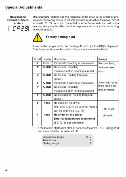
Response to external overtem-
perature
Adjustment range: 0...7Resolution: 1Setting range: 7
This parameter determines the response of the drive to the external tem-perature monitoring circuit. In order to activate this function the power circuit terminals T1, T2 must be connected in accordance with the instruction manual, see page 14. After that the response can be adjusted according to following table:
CP.28 Display Response 0 E.dOH Immediate disabling of modulation 1* A.dOH Quick stop, disabling modulation after reaching speed 0 2* A.dOH Quick stop, holding torque at speed 0 3 A.dOH Immediate disabling of modulation 4* A.dOH Quick stop, disabling modulation after reaching speed 0 5* A.dOH Quick stopping, holding torque at speed 0 6* none No effect on the drive; With CP.31, 32=9 an external module can be controlled (e.g. fan) 7 none No effect on the drive; External temperature monitoring (T1, T2) is not activated!
RestartRemove fault;Activate reset input.
Automatic reset,if the fault is no longer present
- No reset
allowed -
*) If the motor is still too hot after 10 seconds, the error E.dOH is triggered and the modulation is switched off!
Special Adjustments
If overheat no longer exists, the message E.ndOH (or A.ndOH) is displayed. Only then can the error be reset or the automatic restart initiated.
Factory setting = off

31
Special Adjustments
Analog output 1
Analog output 1Amplification
10V
CP.30
100%
-100% 100%
-100%
in
out
Adjustment example :The analog output shall give +10 V at 70 Hz instead of at 100 Hz: CP.30 = 1.43 100 Hz CP.30 = -––––– = 1.43 70 Hz
With the amplification (gain), the output voltage of the analog output can be tuned with respect to the signal. An amplification of 1 corresponds to ±100 % = ±10 V.
Adjustment range: 0...20Resolution: 1Factory setting: 2 Note: Enter-Parameter
Adjustment range: -20.00...20.00Resolution: 0.01Factory setting: 1.00
CP.29 defines the function of analog output 1. Value Function 0 Absolute actual frequency (CP.1) 100Hz= 100% 1 Absolute set frequency (CP.2) 100Hz= 100% 2 Actual frequency (CP.1) ±100Hz= 100% 3 Set frequency (CP.2) ±100Hz= 100% 4 Output voltage (CP.9) 500V= 100% 5 Actual DC voltage (CP.7) 1000V= 100% 6 Phase current (CP.4) 2 x rated current= 100% 7 Active current ± 2 x rated current= 100% 8 Digital ±100Hz= 100% 9 External PID output ±100Hz= 100% 10 Absolute external PID output 100Hz= 100% 11 Absolute active current 2 x rated current= 100% 12 Power module temperature 100 °C= 100% 13 Motor temperature F5G 150 °C= 100% 14 ReservedF5M 15 ReservedF5M 16 ReservedF5M 17 ReservedF5M 18 ReservedF5M 19 Reference frequency F5G ±140Hz= 100% 20 Absolute reference frequency F5G 140Hz= 100%

32
Relay output 1
Relay output 2
Special Adjustments
CP.31 and CP.32 determine the function of the two outputs.CP.31 for relay output 1 (terminal X2A.24...X2A.26)CP.32 for relay output 2 (terminal X2A.27...X2A.29)
The switching level of CP.32 is CP.33!
Value Function 0 No function 1 On; active when unit has voltage applied to it 2 Run signal; also by DC-braking 3 Ready signal (no error) 4 Fault relay 5 Fault relay (no auto-reset) 6 Warning or error message at abnormal stopping 7 Overload alert signal 8 Overtemperature alert signal power modules 9 External Overtemperature alert signal motor 10 Motor thermal relay tripped (OH2) 11 Overtemperature alert signal interior (OHI) 12 Cable breakage on analog input 1 (4...20 mA) 13 Cable breakage on analog input 2 (4...20 mA) F5G only 14 Max. constant current (stall, CP.25) exceeded 15 Max. ramp current (LA-Stop CP.24) exceeded 16 DC-braking active 17 Power off 18 Motor brake control 19 PID control difference > switching level F5G only 20 Actual value= set value (CP.3= Fcon, rcon; not at noP, LS
error,SSF) 21 Accelerate (CP.3 = FAcc, rAcc, LAS) 22 Decelerate (CP.3 = FdEc, rdEc, LdS) 23 Real direction of rotation = set direction of rotation 24 Actual load utilization (CP.6) > 100% 25 Active current > switching level 26 Actual DC voltage (CP.7)>switching level 27 Actual frequency (CP.1) > switching level 28 Set frequency (CP.2) > switching level 29 Ref. point run complete F5G only 30 Actual torque > level F5G only 31 Absolute speed on AN1 > switching level 32 Absolute speed on AN2 > switching level F5G only 33 Absolute. speed on AN3 > switching level F5G only 34 Set value on AN1 > switching level 35 Set value on AN2 > switching level F5G only

33
Value Function
Factory setting CP.31: 4Factory setting CP.32: 27Note: Enter-Parameter
*these functions are currently not supported by the F5G in the B housing.
Special Adjustments
36 Set value on AN3 > switching level F5G only 37 Timer 1 > switching level 38 Timer 2 > switching level 39 Reserved F5M 40 Hardware current limit active 41 Modulation on-signal 42 ANOUT3 PWM 43 ANOUT4 PWM F5G only 44 Inverter status (ru.0) = switching level 45 Power transistor temperature > switching level 46 Motor temperature > switching level 47 Ramp output > switching level 48 Phase current > switching level 49 Rotation forward 50 Rotation reverse 51 OL2 warning F5G only 52…58 Reserved F5M 59 Digital input (ru.22 "AND" > switching level F5B only* 60 Digital input (ru.22 "OR" > switching level F5B only* 61 Digital input (ru.22 "NAND" > switching level F5B only* 62 Digital input (ru.22 "NOR" > switching level F5B only* 63 Absolute value ANOUT1 > switching level F5B only* 64 Reserved F5B only* 65 Absolute speed on ANOUT1 > switching level F5B only* 66 Reserved F5B only* 67…69 Reserved F5M 70 Driver voltage aktiv ( safety relais) 71…72 Reserved F5M 73 Absolute value active power > switching level 74 active power > switching level 75…79 Reserved F5M 80 Active current > switching level 81 Real value channel 1 > switching level 82 Real value channel 2 > switching level 83 HSP5 bus synchronized 84 Reserved F5M

34
The source of the direction command is defined with this parameter. With CP.34 one does not modify the direction command of the fixed frequencies (CP.19... 21). This parameter is an "Enter" parameter.
Value Function 0 Digital selection (op.2); negative set values are set to zero 1 Digital selection (op.2); the sign of the value has no effect on
the direction of rotation 2 Setting by way of terminal strip forward/ reverse; negative
set values are set to zero (factory setting) 3 Setting by way of terminal strip forward/ reverse; the sign of
the set value has no effect on the direction of rotation; the speed is the absolute value of the set value
4 Setting by way of terminal strip run, stop (X2A.14) and forward, reverse (X2A.15); negative values are set to zero
5 Setting by way of terminal strip run, stop (X2A.14) and forward, reverse; the signs of the set value has no effect on the direction of rotation; speed is the absolute value
6 Set value dependent, positive value - clockwise rotation; negative value- counterclockwise rotation; with set value "0" the unit is switched into status "Low speed" (LS)
7 Set value dependent, positive value - clockwise; negative values - counterclockwise, however no (LS) at zero
8 Control word (sy.50); negative set values are set to zero 9 Control word (sy.50); the sign of the set value has no effect
on the direction of rotation
Special Adjustments
Relay output 2Switching level
This parameter determines the switching point for the relay output 2 (CP.32). After the switching of the relay, this value can move within a 0.5 Hz window (hysteresis), without the relay changing states. Since the operator display can only view 5 characters, the last digits are not displayed for the higher values.
Adjustment range: -30000.00...30000.00Resolution: 0.01Factory setting: 4.00Hysteresis Levels Frequency: 0.5 HzActual DC voltage: 1 VAnalog set value: 0.5 %Active current: 0.5 A
Source of rotation direction

35
Set value0-limited(Value 2 and 4)
Set valueabsolute(Value 3 and 5)
Adjustment range: 0...9Resolution: 1Factory setting: 2 Note: Enter-Parameter
10V100%
-100% 100%
-100%
extern
-10V
interninternal
external
10V100%
-100% 100%
-100%
extern
-10V
interninternal
external
AN1 Interface selection
The analog input 1 (AN1) can accept different types of signals. In order to correctly evaluate the signal, this parameter must be adjusted to match the signal source.
Value Analog reference signal 0 0...±10 V DC, Rin=56 kOhm 1 0...± 20 mA DC, Rin=250 Ohm 2 4...20 mA DC, Rin=250 Ohm
Adjustment range: 0...2Resolution: 1Factory setting: 0 Note: Enter-Parameter
Special Adjustments

36
Adjustment range: -10.0...10.0 %Resolution: 0.1 %Factory setting: 0.2 %
AN1 Zero point hysteresis
Noise coupled capacitively or inductively into the analog signal wires can cause the motor to drift in spite of the filtering of the analog input. The zero point hysteresis can be used to suppress this noise and therefore prevent the motor from drifting. With parameter CP.36 the analog signal AN1 (X2.1,X2.2) can be masked in the range of 0...±10.0% (0...±1.00V). The adjusted value is valid for both directions of rotation.
If a negative percentage value is adjusted then the hysteresis is not only effective at the zero point but also around the actual set value. This means changes to the set value during constant operation are accepted only when the change is larger than the adjusted hysteresis.
Special Adjustments

37
Drive Mode
4.7 The "Drive Mode"
The Drive Mode is a operating mode of KEB COMBIVERT that permits the manual starting of the through the keypad display unit. After applying a signal to the control release terminal 16, the set value (speed ref.) and rotation setting are effected exclusively over the keypad. In order to activate the Drive Mode the corresponding password (500) must be entered in CP.0. The display switches over as follows.
Direction of rotationF= forward, r= reverse
StatusnoP= "control release" deactivatedLS= neutral position
Set frequency can be changed with the UP/DOWN keys while holding the FUNC/SPEED key
4.7.1 Start / Stop Drive
4.7.3 Speed set-ting
4.7.2 Changing the Direction of Rotation
FUNC.
SPEED
STOPSTART
ENTER
F/R
To exit the Drive Mode the inverter must be in status “stop” (Display noP or LS). Press the FUNC and ENTER keys simultaneously for about 3 seconds to leave the Drive Mode. The CP-parameters appear in the display.
4.7.4 Leaving the "Drive Mode"
START
STOP
Modulation blocked,Drive in standby mode
Drive decreases to 0 Hz and switches the modulation off
Drive accelerates up to the adjusted set value (speed ref.)
Drive operates with adjusted set value (speed ref.)
Drive changes direction of rotation
The display changes when the FUNC/SPEED key is pressed. The set frequency is displayed.
FUNC.
SPEED + ENTER
F/Rfor 3 seconds

38
Error Diagnosis
5. Error Diagnosis KEB COMBIVERT Error messages are always represented with an "E.xx" and the appropriate error code in the display. Errors cause the immediate turn off of the output to the motor. Restart is possible, only after reset. Malfunctions are represented with an "A.xx" and the appropriate code. Responses to malfunctions can vary depending on the programmed condition.In the following table the error codes and their causes are described.
Display Description Value Meaning E. OP ERROR over voltage 1 Error: Overvoltage (DC-bus circuit)
Occurs, if DC-bus voltage rises above the permissible value. Causes: • poor control adjustment (overshooting) • input voltage too high • interference voltages at the input • deceleration ramps too short • braking resistor damaged or undersized
E. UP ERROR under voltage 2 Error: Under voltage (DC-bus circuit). Occurs, if DC-bus voltage falls below the permissible value. Causes: • input voltage too low or instable • inverter rating too small • voltage losses through wrong cabling • the supply voltage through generator / transformer breaks down at very short ramps • one phase of the input voltage is missing (ripple-detection) • with separate supply and switched off power circuit
E. OC ERROR over current 4 Error: Over current Occurs, if the specified peak current is exceeded. Causes: • acceleration ramps too short • the load is too big at turned off acceleration stop and turned off constant current limit • short-circuit at the output • ground fault • deceleration ramp too short • motor cable too long • EMC
E.OHI ERROR overheat internal 6 Error: Overheating in the interior: error can only be reset once the drive displays E.nOHI; this means the interior temperature has fallen by at least 3°C
E.nOHI no ERROR overheat int. 7 No longer overheating in the interior E.OHI, interior temperature has fallen by at least 3°C
E. OH ERROR overheat pow.mod. 8 Error: Overtemperature of power module. Error can only be reset at E.nOH. Causes: • insufficient air flow at the heat sink (soiled) • ambient temperature too high • fan clogged
E.dOH ERROR drive overheat 9 Error: Overtemperature signal from motor temperature sensor. Error can only be reset at E.ndOH, when sensor resistance decre-ases. Causes: • resistor at the terminals T1, T2 >1650 Ohm

39
Error Diagnosis
• motor overloaded • line breakage to the temperature sensor
E.nEd no ERROR detected 10 No defined error recognized (should not occur) E.ndOH no ERROR drive overheat 11 No longer overtemperature of motor Temperature SENSOR,
SENSOR is again low-resistance.E. PU ERROR power unit 12 Error: General power circuit fault NO.PU power unit not ready 13 Power circuit not ready E.PUIN ERROR power unit invalid 14 Error: Software version for power circuit and control card are
different. Error cannot be reset. E.LSF ERROR load shunt fault 15 Error: charging relay does not close after the DC bus voltage
reaches its normal operating level. Occurs for a short time during the switch-on phase, but must automatically be reset immediately (after 10 sec's E.UP). If the error message remains, the following causes may be applicable: • load-shunt defective • input voltage incorrect or too low • high losses in the supply cable • braking resistor incorrectly connected or damaged • braking module defective
E. OL ERROR overload 16 Error: Overload error can only be reset at E.nOL, if OL-counter has again reached 0%. Occurs, if an excessive load is applied longer than the permissible time (see technical data). Causes: • poor control adjustment (overshooting) • mechanical fault or overload in the application • inverter not correctly sized for application • motor incorrectly wired
E.nOL no ERROR overload 17 No more overload, OL-counter has reached 0%; after the error E.OL a cooling phase must elapse. This message appears upon completion of the cooling phase. The error can be reset. The inverter must remain switched on during the cooling phase.
E.buS ERROR bus 18 Error: Adjusted time (Watchdog) of communication between operator and communication bus has been exceeded.
E.OL2 ERROR overload 2 19 Error: Overload while running below 3 Hz. Can only be reset at E.nOL2, if cool-down time has elapsed.
E.nOL2 no ERROR overload 2 20 No more overload, the cool-down time is terminated.E.EEP E. EEPROM defective 21 Error: EEPROM defective. After reset the error is repeated. (para-
meter values changed are erased in the EEPROM) E.PUCO E. power unit common. 22 Error: Parameter value could not be written to the power circuit.
Acknowledgment from PC <> OKE.OH2 ERROR motor protection 30 Error: Electronic motor protective relay has tripped. E. EF ERROR external fault 31 Error: External error is triggered when a digital input is being
programmed as an external error input. E.ENC ERROR encoder 32 Error: Encoder cable and/or connection wiringE.nOH no E. over heat pow. mod. 36 Internal or external temperature has dropped to a safe level.E.SET ERROR set 39 Error: Set selection: It has been attempted to select a locked
parameter set. E.PRF ERROR prot. rot. for. 46 Error: Locked direction of rotation clockwise E.PRR ERROR prot. rot. rev. 47 Error: Locked direction of rotation counterclockwise E.PUCI E. power unit code inv. 49 Error: during the initialization the power circuit could not be recog-
nized or was identified as invalid. E.PUCH E. power unit changed 50 Error: Power circuit identification was changed; with a valid power
circuit this error can be reset by writing to SY.3 (application mode).E.DRI ERROR driver relay 51 Error: Driver relay. Relay for driver voltage on power circuit has
not picked up although control release was given. E.HYB ERROR hybrid 52 Error: Invalid encoder interface identifier

40
Error Diagnosis
E.CO1 ERROR counter overrun 1 54 Error: Counter overflow encoder channel 1 E.CO2 ERROR counter overrun 2 55 Error: Counter overflow encoder channel 2 E. BR ERROR brake 56 Error: This error can occur in the case of switched on brake cont-
rol, if the load is below the minimum load level Pn.58 (application mode) at start up.
E.INI ERROR initialization MFC 57 Error: MFC not booted E.HYBc ERROR hybrid changed 59 Error: Encoder interface identifier has changed, it must be confir-
med over ec.0 or ec.10 (application mode).E.ccd ERROR calculation drive 60 Error: during the automatic motor stator resistance measurementE.OS ERROR over speed 105 Error: Real frequency is bigger than the max. Output frequencyA.OHI ABN.STOP overheat int. 87 Warning: overtemperature in the interior A.nOH no A. overheat pow.mod. 88 Warning: no more overtemperature of power module A. OH A.STOP overheat pow.mod 89 Warning: Overtemperature of power module A. EF ABN.STOP external fault 90 Warning: external error A.ndOH no A. drive overheat 91 Warning: no more overtemperature of motor TEMPERATURE
SENSOR. Motor SENSOR is low-resistance again. A.nOHI no A.STOP overheat int. 92 Warning: no more overtemperature in the interior A.buS ABN.STOP bus 93 Warning: Watchdog for communication between operator/control
card has respondedA.PRF ABN.STOP prot. rot. for. 94 Warning: locked direction of rotation clockwise A.PRR ABN.STOP prot. rot. rev. 95 Warning: locked direction of rotation counterclockwise A.dOH ABN.STOP drive over heat 96 Warning: overtemperature of motor TEMPERATURE SENSORA.OH2 ABN.STOP motor protect. 97 Warning: electronic motor protective relay has tripped A.nOL no ABN.STOP overload 98 Warning: no more overload, OL counter has reached 0 %. A. OL ABN.STOP overload 99 Warning: Overload can only be reset at A.nOL, if OL counter has
again reached 0 %A.OL2 ABN.STOP overload 2 100 Warning: Overload can only be reset at A.nOL2, if cool-down time
has elapsed A.nOL2 no ABN.STOP overload 2 101 Warning: no more overload, the cool-down time has elapsed.A.SET ABN.STOP set 102 Warning: set selection: It has been attempted to select a locked
parameter set.

41
6. Quick Reference
Display Parameter Adjust. range Resolution Cust. settingCP. 0 Password input 0...9999 1 read onlyCP. 1 Actual frequency display – 0.0125 Hz read onlyCP. 2 Set frequency display – 0.0125 Hz read onlyCP. 3 Inverter status display – – read onlyCP. 4 Phase current – 0.1 A read onlyCP. 5 Phase current, Peak value – 0.1 A read onlyCP. 6 Actual load – 1 % read onlyCP. 7 Actual DC voltage – 1 V read onlyCP. 8 Actual DC voltage, Peak value – 1 V read onlyCP. 9 Output voltage – 1 V read onlyCP.10 Minimum frequency 0…400 Hz 0.0125 Hz ___________CP.11 Maximum frequency 0…400 Hz 0.0125 Hz ___________CP.12 Acceleration time 0.01…300.00 s 0.01 s ___________CP.13 Deceleration time(-1 see CP.12) -1; 0.01…300.00 s 0.01 s ___________CP.14 S-curve time 0.00 (off)…5.00 s 0.01 s ___________CP.15 Torque boost 0.0…25.5 % 0.1 % ___________CP.16 Rated frequency 0…400 Hz 0.0125 Hz ___________CP.17 1) Voltage stabilization 1…650 V (off) 1 V ___________CP.18 1) Carrier frequency 2/4/8/12/16 kHz – ___________CP.19 Fixed frequency 1 -400...400 Hz 0.0125 Hz ___________CP.20 Fixed frequency 2 -400...400 Hz 0.0125 Hz ___________CP.21 Fixed frequency 3 -400...400 Hz 0.0125 Hz ___________CP.22 1) DC-braking, Mode 0…9 1 ___________CP.23 DC-braking, Time 0.00…100.00 s 0.01 s ___________CP.24 Max. ramp current 0…200 % 1 % ___________CP.25 Max. constant current 0…200 % (off) 1 % ___________CP.26 1) Speed search condition 0…15 1 ___________CP.27 Quick stop time 0.00…300.00 s 0.01 s ___________CP.28 Response of ext. overtemperature 0…7 1 ___________CP.29 1) Analog output 1 0…12...20 F5G 1 ___________CP.30 Analog output 1, Amplification -20.00…20.00 0.01 ___________CP.31 1) Relay output 1 0…58...66 F5B 1 ___________CP.32 1) Relay output 2 0…58...66 F5B 1 ___________CP.33 Relay output 2, Switching level ±30000.00 0.01 ___________CP.34 1) Source of rotation direction 0…9 1 ___________CP.35 1) AN1 interface selection 0…2 1 ___________CP.36 AN1 zero point hysteresis -10.0…10.0 % 0.1 % ___________

42
When switching on the KEB COMBIVERT F5, the value of parameter CP.1 appears in the operator display. (see "Drive Mode" to switch the keypad function)
The function key (FUNC) changes between the parameter value and parameter number.
With UP and DOWN, the value of the parameter number is increased/de-creased.
Password Input
FUNC.
SPEED
START
FUNC.
SPEED
ENTER
F/R
FUNC.
SPEED
START
FUNC.
SPEED
ENTER
F/R
Releasing the CP-Parameters
Locking the CP-Parameters(Read only)
From the factory, the frequency inverter is supplied without pass-word protection, this means that all parameters can be adjusted. After programming, the unit can be protected against unauthorized access thus preventing the values from being changed.
Quick Reference
Parameter Display
FUNC.
SPEED
STARTSTOP
STARTSTOP

You can find supplementary manuals and intructions which can be downloaded from
www.kebamerica.com
General instructions• Part 1 EMC-and safety instructions for CE instalations (Must be supplied when unit is shipped to Europe)
Unit-specific instructions• Part 2 Power Circuit for complete power range • Part 3 Control Circuit for B/G, M, or S version
Service notes• Up/Download of parameter lists with KEB COMBIVERT• Error messages
Detailed Instructions and information for application design and development• Application Manual• Preparation of a user-defined parameter menu• Programming of the digital inputs
All documents are also available in printed version, please contact your local sales office. Some of the above doucmentation is free while some of it must be purchased.

© K
EB
00
.F5.
BU
M-K
A02
02
/200
6
Karl E. Brinkmann GmbHFörsterweg 36-38 • D-32683 Barntrup
fon: +49 5263 401-0 • fax: +49 5263 401-116net: www.keb.de • mail: [email protected]
KEB Antriebstechnik GmbH & Co. KGWildbacher Str. 5 • D–08289 Schneeberg
fon: +49 3772 67-0 • fax: +49 3772 67-281mail: [email protected]
KEB Antriebstechnik Austria GmbHRitzstraße 8 • A-4614 Marchtrenk
fon: +43 7243 53586-0 • fax: +43 7243 53586-21net: www.keb.at • mail: [email protected]
KEB AntriebstechnikHerenveld 2 • B-9500 Geraadsbergen
fon: +32 5443 7860 • fax: +32 5443 7898mail: [email protected]
KEB Power Transmission Technology (Shanghai) Co. Ltd.Industry Development District
No. 28 Dongbao Road Song JiangCHN-201613 Shanghai, PR. China
fon: +86 21 51 099 995 • fax: +86 21 67 742 701net: www.keb.cn • mail: [email protected]
KEB Antriebstechnik Austria GmbHOrganizační složka
K. Weise 1675/5 • CZ-370 04 České Budějovicefon: +420 387 699 111 • fax: +420 387 699 119net: www.keb.cz • mail: [email protected]
KEB EspañaC/ Mitjer, Nave 8 - Pol. Ind. LA MASIA
E-08798 Sant Cugat Sesgarrigues (Barcelona)fon: +34 93 897 0268 • fax: +34 93 899 2035
mail: [email protected]
Société Française KEBZ.I. de la Croix St. Nicolas • 14, rue Gustave Eiffel
F-94510 LA QUEUE EN BRIEfon: +33 1 49620101 • fax: +33 1 45767495
net: www.keb.fr • mail: [email protected]
KEB (UK) Ltd.6 Chieftain Buisiness Park, Morris Close
Park Farm, Wellingborough GB-Northants, NN8 6 XFfon: +44 1933 402220 • fax: +44 1933 400724
net: www.keb-uk.co.uk • mail: [email protected]
KEB Italia S.r.l.Via Newton, 2 • I-20019 Settimo Milanese (Milano)
fon: +39 02 33500782 • fax: +39 02 33500790net: www.keb.it • mail: [email protected]
KEB - YAMAKYU Ltd.15–16, 2–Chome, Takanawa Minato-ku
J–Tokyo 108-0074fon: +81 33 445-8515 • fax: +81 33 445-8215
mail: [email protected]
KEB Polskaul. Budapesztańska 3/16 • PL–80-288 Gdańskfon: +48 58 524 0518 • fax: +48 58 524 0519
mail: [email protected]
KEB Taiwan Ltd.No.8, Lane 89, Sec.3; Taichung Kang Rd.
R.O.C.-Taichung City / Taiwanfon: +886 4 23506488 • fax: +886 4 23501403
mail: [email protected]
KEB Korea SeoulRoom 1709, 415 Missy 2000
725 Su Seo Dong, Gang Nam GuROK-135-757 Seoul/South Korea
fon: +82 2 6253 6771 • fax: +82 2 6253 6770mail: [email protected]
KEB SverigeBox 265 (Bergavägen 19)
S-43093 Hälsöfon: +46 31 961520 • fax: +46 31 961124
mail: [email protected]
KEB America, Inc.5100 Valley Industrial Blvd. South
USA-Shakopee, MN 55379fon: +1 952 224-1400 • fax: +1 952 224-1499
net: www.kebamerica.com • mail: [email protected]