combustion noise s. moreau in modern aero-engines
TRANSCRIPT
Issue 7 - June 2014 - Combustion Noise in Modern Aero-Engines AL07-05 1
Aeroacoustics
Combustion Noise in Modern Aero-Engines
I. Duran(Cerfacs, Snecma)S. Moreau(Universite de Sherbrooke)F. Nicoud (Universite Montpellier)T. Livebardon(Cerfacs, Turbomeca)E. Bouty(Turbomeca)T. Poinsot(Institut de Mecanique des Fluides de Toulouse)
E-mail: [email protected]
DOI : 10.12762/2014.AL07-05
Combustion noise has recently been the subject of attention of both the aeroacoustic and the combustion research communities. Over the last decades, engine manu-
facturers have made important efforts to significantly reduce fan and jet noise, which increased the relative importance of combustion noise. Two main mechanisms of combustion-noise generation have been identified: direct combustion noise, generated by acoustic waves propagating to the outlet, and indirect combustion noise, caused by the acceleration of entropy waves (or hot spots) and vorticity waves through turbine blades. The purpose of this paper is to describe some of the predicting tools used in combustion noise, as well as to present an overview on some recent experimental studies.
Introduction
Noise emissions are a major concern for both aircraft and engine manufacturers. This is mainly caused by increasing restrictions and regulations regarding the global noise generated by aircraft during take-off and landing. At the same time, aircraft operators are concerned with passenger comfort and therefore demand a quieter cabin. Noise has become another pollutant source due to engines and airframe, which must be controlled both outside and inside air-craft and helicopters. For these reasons, the reduction of acoustic emissions is now a major field of research both for industry and research groups.
The first studies on the subject, carried out by Lighthill [32], showed the great importance of jet noise among the overall noise emissions. This was done in the context of the recently adopted jet engine, which was significantly louder than its helix-propelled predeces-sors. Lighthill showed that the jet-noise source scaled with the eighth power of the jet-exhaust speed, meaning that doubling the jet speed would lead to an increase of acoustic intensity level of nearly 50 dB. Jet speed reduction was at the time not only a noise concern, but also a performance requirement, since the propulsive efficiency increased significantly when the jet speed was reduced, increasing aircraft range and reducing cost. The turbofan engine used nowa-days achieved these goals, reducing jet speed and maintaining the total thrust by increasing the mass-flow using a by-pass design. The increase in the propulsive efficiency and the noise reduction were significant, but the increase in air trafic and the construction of airports near residential areas forced aircraft manufacturers to
further decrease the global noise emissions. At the same time, fuel costs and environmental concerns lead to further research on consumption reduction. The reduction of jet speed may reach a limit soon, since too high a by-pass ratio leads to heavier engines and therefore higher fuel consumption. Research on jet noise reduction continued in different directions, leading to solutions that were, in many cases, opposed to those reducing fuel consumption and for which a compromise had to be found. Chevrons, for example, were adopted to enhance the jet mixing at the outlet of the nozzle, in order to reduce jet noise, but this mechanism also had an impact on the propulsion, reducing the total thrust of the engine and therefore increasing the fuel consumption.
Other noise sources started to increase their relative contribution, as jet noise was significantly reduced. Firstly, the turbofan engine with high by-pass ratio reduced the jet noise, but at the same time added a significant contribution: the fan noise. As jet noise was being re-duced, research on fan and turbomachinery noise increased, since there was still significant room for improvement. Airframe, landing gear, flap and slat noise were also considered, since they mostly contribute under approach conditions. Combustion noise was ini-tially addressed in the work of Strahle [47], Chiu and Summerfield [5], Hassan [17], Marble and Candel [33], and Cumpsty and Marble [8], however, its relative contribution to the global aircraft acous-tic emissions was still low. It was not until the development of the new low NOx-emission combustion chambers, such as lean pre-mixed, rich-quench-lean or staged-injection combustion chambers, that noise emissions from the combustion chamber increased their relative contribution and started to be a major concern. These new

Issue 7 - June 2014 - Combustion Noise in Modern Aero-Engines AL07-05 2
combustion chamber concepts have been adopted to reduce NOx emissions [40], but their design has two major issues. On the one hand, they can present combustion instabilities when the turbulent flame interacts with the acoustics of the chamber in a constructive way, increasing the acoustic energy, which can lead not only to high levels of noise but also to severe damage of the combustion system, where noise levels can exceed 200 dB. On the other hand, and as the main subject of this paper, the turbulent flame induces larger heat release fluctuations as the mixture approaches the lean extinction point. These heat release fluctuations generate two types of waves, acoustic and entropy, which are responsible for the two combustion noise generation mechanisms discussed in the fol-lowing sections.
The rest of this paper is structured as follows: First, the two com-bustion noise generation mechanisms are presented. A description of computational methods to predict combustion noise in modern aero-engines is given and insights on previous, present and future expe-riments will follow. Conclusions and perspectives are finally drawn.
The two combustion noise generation mechanisms
Combustion noise is generated inside the combustion chamber and has to propagate through turbine blades. The problem of acoustic wave propagation through accelerating flows was first studied by Tsien [52] in a rocket engine combustion instability framework. It was Marble and Candel [33], however, who first included the pro-pagation of entropy waves through accelerating subsonic and su-personic nozzles, explaining the two combustion noise generation mechanisms: direct and indirect, as seen in figure 1. Direct noise is generated by the acoustic waves produced in the flame region, which travel downstream through the turbine stages to the outlet. Indirect combustion noise is generated by the entropy waves induced by the unsteady combustion process. These waves generate noise when propagating through non-homogeneous flows, such as the turbine stages.
Reactiveturbulent
flow
Acousticwaves
Entropywaves Indirect
noise
Directnoise
Turbineblades
Figure 1: The two combustion noise mechanisms
Indirect combustion noise
Any heat release generates entropy, as described by the equation
· lnwith vs Q pu s s ct T γρ ρ
∂+ ∇ = = ∂
(1)
where the usual definition of entropy is used. It is therefore straight-forward to conclude that an unsteady heat release q' of this heat
source (due to turbulence for example) generates a fluctuating entro-py term, s' , given by a linearization
· ,withp
s q p s pu s u u st T p c p
ρρ γ ρ
′ ′ ′ ′ ′ ′ ∂ ′ ′+ ∇ = − + ∇ = − ∂
(2)
as shown by Dowling et al. [9] where the mean steady quantities are represented by the non-primed variables for simplicity. This equation shows first that entropy fluctuations are generated by both the flame fluctuations ( ')q and by acoustic fluctuations in regions with mean heat release (second term on the right hand side). At the same time, it shows that once generated, in the region outside the flame where no mean or fluctuating heat release exists, the right-hand-side of Eq. (2) is zero and the entropy wave is just convected with the mean flow velocity ( )u when neglecting any flow mixing or diffusion. Marble and Candel [33] showed that a one-way coupling between entropy and acoustics appeared when a flow gradient existed in a quasi-1D nozzle. Using the quasi-1D linearized Euler equations for the flow through the nozzle (neglecting heat release and diffusion),
0p uu ut x p x uγ
′ ′ ∂ ∂ ∂ + + = ∂ ∂ ∂ (3)
22 ( 1)
p
u c p s u p duut x u u x p c u p dx
γγ γ
′ ′ ′ ′ ′ ∂ ∂ ∂ + + = − + − ∂ ∂ ∂ (4)
0p
sut x c
′∂ ∂ + = ∂ ∂ (5)
the coupling between the entropy and acoustics appears on the right hand side of eq. (4), where the entropy wave appears multiplied by the velocity gradient, du/dx. If the flow is homogeneous with no acce-leration, the right hand side of eq. (4) is zero and the well-known re-sult for acoustic propagation in non-zero but constant-Mach-number flows is recovered from eqs. (3) and (4). However, when considering a mean flow gradient, the coupling between convective and acous-tic waves appears: the entropy wave acts as a source term in the acoustic equation, generating entropy or indirect combustion noise. This mechanism, which converts entropy waves into acoustic noise, has been extensively studied from an experimental [2], analytical [53, 18, 44, 19, 31, 11, 20] and numerical point of view [24, 30, 50, 51].
Direct combustion noise
As seen in the second part of eq. (2), the entropy wave has an associated density fluctuation. In the near region of the flame, this density fluctuation is generated by the unsteady heat release and generates a velocity perturbation (acoustic wave) due to the mass conservation equation. This mechanism generates acoustic waves directly in the flame region as a monopole source [25], which pro-pagate through the turbine stages, generating direct combustion noise. In free space, an acoustic analogy can be used to propa-gate this noise source. For example, when considering Phillips’ analogy [38], which was extended to reactive flows by Chiu and Summerfield [5] and Kotake [25], the wave equation reads,
22
2 2( 1)
Ti i
D Dcx x DtDt c
π π γ ωρ
∂ ∂ −− = ∂ ∂
(6)
Issue 7 - June 2014 - Combustion Noise in Modern Aero-Engines AL07-05 3
where =(1/)ln(p/p∞) and Tω is the heat release of the flame. Only this direct combustion noise contribution has been retained, for simplicity, to illustrate the monopole nature of combustion noise at low Mach numbers. Direct combustion noise has been studied analytically [46, 47], combining numerical simulations and acoustic analogies [22, 21, 48, 49] and experimentally [41]. These studies are mostly performed for free unconfined flames, a situation that is never observed in an engine.
The indirect mechanism can be of great importance in modern aero-engines due to the large accelerations of the flow in the tur-bine blades, as seen by [4, 36, 39]. Leyko et al. [28] showed that, for a 1D model combustor with a choked nozzle, indirect noise can be one order of magnitude larger than direct noise, depending on the mean Mach number in the combustion chamber. An order of magnitude can be useful here: sending a 10K temperature fluctua-tion through a choked nozzle can produce a pressure oscillation of up to 40 Pa at the outlet.
Both combustion noise generation mechanisms depend strongly on the propagation of waves through turbine stages: direct noise is shielded by the effect of the turbine blades and the successive accelerations and decelerations of the mean flow, while entropy noise is, on the other hand, generated by these accelerations and decelerations. For this reason, the study and the prediction of combustion noise has focused both on the generation of waves by the flame in the chamber and on the propagation of waves through non-uniform flows, which is typical of turbine stages.
Predicting combustion noise in modern aero-engines
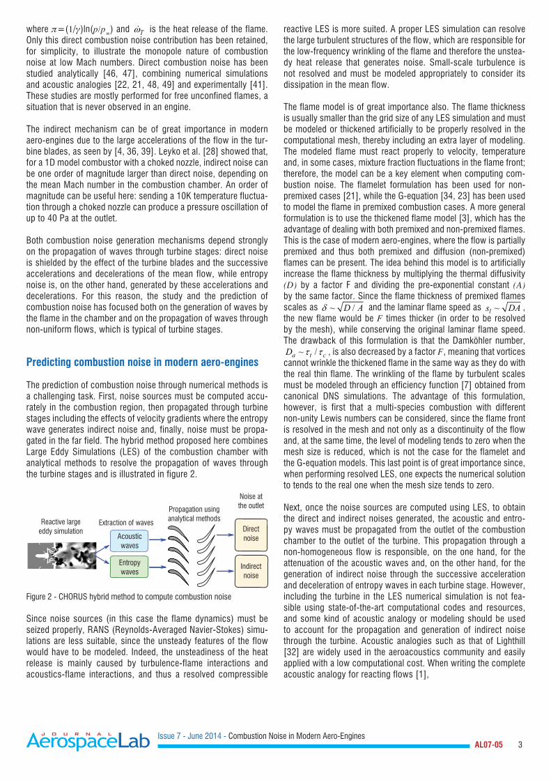
The prediction of combustion noise through numerical methods is a challenging task. First, noise sources must be computed accu-rately in the combustion region, then propagated through turbine stages including the effects of velocity gradients where the entropy wave generates indirect noise and, finally, noise must be propa-gated in the far field. The hybrid method proposed here combines Large Eddy Simulations (LES) of the combustion chamber with analytical methods to resolve the propagation of waves through the turbine stages and is illustrated in figure 2.
Entropywaves
Acousticwaves
Reactive largeeddy simulation
Propagation usinganalytical methodsExtraction of waves
Directnoise
Noise atthe outlet
Indirectnoise
Figure 2 - CHORUS hybrid method to compute combustion noise
Since noise sources (in this case the flame dynamics) must be seized properly, RANS (Reynolds-Averaged Navier-Stokes) simu-lations are less suitable, since the unsteady features of the flow would have to be modeled. Indeed, the unsteadiness of the heat release is mainly caused by turbulence-flame interactions and acoustics-flame interactions, and thus a resolved compressible
reactive LES is more suited. A proper LES simulation can resolve the large turbulent structures of the flow, which are responsible for the low-frequency wrinkling of the flame and therefore the unstea-dy heat release that generates noise. Small-scale turbulence is not resolved and must be modeled appropriately to consider its dissipation in the mean flow.
The flame model is of great importance also. The flame thickness is usually smaller than the grid size of any LES simulation and must be modeled or thickened artificially to be properly resolved in the computational mesh, thereby including an extra layer of modeling. The modeled flame must react properly to velocity, temperature and, in some cases, mixture fraction fluctuations in the flame front; therefore, the model can be a key element when computing com-bustion noise. The flamelet formulation has been used for non-premixed cases [21], while the G-equation [34, 23] has been used to model the flame in premixed combustion cases. A more general formulation is to use the thickened flame model [3], which has the advantage of dealing with both premixed and non-premixed flames. This is the case of modern aero-engines, where the flow is partially premixed and thus both premixed and diffusion (non-premixed) flames can be present. The idea behind this model is to artificially increase the flame thickness by multiplying the thermal diffusivity (D) by a factor F and dividing the pre-exponential constant (A) by the same factor. Since the flame thickness of premixed flames scales as ~ /D Aδ and the laminar flame speed as ~ls DA , the new flame would be F times thicker (in order to be resolved by the mesh), while conserving the original laminar flame speed. The drawback of this formulation is that the Damköhler number,
~ /a t cD τ τ , is also decreased by a factor F, meaning that vortices cannot wrinkle the thickened flame in the same way as they do with the real thin flame. The wrinkling of the flame by turbulent scales must be modeled through an efficiency function [7] obtained from canonical DNS simulations. The advantage of this formulation, however, is first that a multi-species combustion with different non-unity Lewis numbers can be considered, since the flame front is resolved in the mesh and not only as a discontinuity of the flow and, at the same time, the level of modeling tends to zero when the mesh size is reduced, which is not the case for the flamelet and the G-equation models. This last point is of great importance since, when performing resolved LES, one expects the numerical solution to tends to the real one when the mesh size tends to zero.
Next, once the noise sources are computed using LES, to obtain the direct and indirect noises generated, the acoustic and entro-py waves must be propagated from the outlet of the combustion chamber to the outlet of the turbine. This propagation through a non-homogeneous flow is responsible, on the one hand, for the attenuation of the acoustic waves and, on the other hand, for the generation of indirect noise through the successive acceleration and deceleration of entropy waves in each turbine stage. However, including the turbine in the LES numerical simulation is not fea-sible using state-of-the-art computational codes and resources, and some kind of acoustic analogy or modeling should be used to account for the propagation and generation of indirect noise through the turbine. Acoustic analogies such as that of Lighthill [32] are widely used in the aeroacoustics community and easily applied with a low computational cost. When writing the complete acoustic analogy for reacting flows [1],

Issue 7 - June 2014 - Combustion Noise in Modern Aero-Engines AL07-05 4
( )
( )
( )
2
2 2
2
2
2
2
1 2 2
1
ln
1 1
i j iji ji
k i iT k ij
k i jk
e jj
p u uc x xt x
J q uh Qx x xc
t D rDt
c p pDp Dc t D Dtc
ux t
p
t
ρ τ
γρ ω τρ
ρ
ρ ρρρ
ρ
∞
∞
∞
∞ ∞ ∞
∞
∂− = −
∂∂ ∂
−+ − + + ∂ ∂ ∂ ∂ + ∂
+
−+ − − ∂
∂+∂
∂ ∂
∂ ∂ ∂
∂
∑
(7)
the indirect combustion noise source (last line) appears on the right hand side of the wave equation, in terms of the excess density, e =(−∞)−(p −p∞)/c∞, i.e, the density fluctuation that arises over and above isentropic acoustic contributions and associated with entropy fluctuations. A first drawback, however, is that the mean flow is considered at rest in the propagation region and therefore indirect noise, generated where velocity gradients are strong in the mean flow, cannot be predicted using this method and must be given in advance. Moreover, an acoustic analogy requires the medium to be broken down into a source region and a propagation zone, which can hardly be done in the indirect noise context. Assuming that the sound can be split into generation and propagation, the source term given by the excess density (right hand side of Eq(7)) must be part of the sources solved by LES to be propagated by the wave operator (left hand side of Eq(7)), which remains a daunting task.
The alternative is to solve analytically (under several assumptions) the propagation of waves through the non-homogeneous flow. Marble and Candel [33] first solved the propagation of waves through a qua-si-1D subsonic and supersonic nozzle analytically using the compact assumption, where the wavelength of the waves is small compared to the nozzle transversal length (and therefore the result is valid in the low frequency range only). Thus, the linearized Euler equations (3)-(5) are assumed to be quasi-steady, giving three jump conditions between the inlet (i) and the outlet (o) corresponding to the mass, total temperature and entropy fluctuations, namely
i o
m mm m′ ′ =
(8)
t t
t ti o
T TT T ′ ′
= (9)
p pi o
s sc c
′ ′=
(10)
These matching conditions are written as a function of the dimen-sionless upstream and downstream acoustic propagating waves w+, w− and entropy wave ws defined in Eq((11), (12) and (13)) and solved analytically. Fully analytical solutions exist also when considering non-compact frequencies for a specific nozzle geometry [52, 33, 35, 15], for any nozzle geometry using an asymptotic expansion up to first order [45, 16] and, more recently, using the Magnus expansion for any frequency and any nozzle geometry [10]. These methods, however, are based on a quasi-1D formulation, neglecting the real 3D flow of the turbine and, in particular, the flow deviation imposed by the stator and rotor blades.
p uwp cγ γ
+ ′ ′= + (11)
p uwp cγ γ
− ′ ′= − (12)
s
p
swC′
= (13)
Cumpsty and Marble [8] used the same compact assumption as Marble and Candel [33] to write the jump conditions of the acoustic and entropy waves, as well as vorticity waves wv,
vw ξω′
= (14)
where ξ ′ is a vorticity fluctuation, through a two-dimensional sta-tor blade row combining Marble’s equation’s with the Kutta condition at the outlet of the row. This formulation is still based on the same compact assumption and is therefore only valid for low frequencies, but considers the 2D azimuthal component of the flow though neglec-ting radial effects, which are small below the radial cut-off frequency, which is typically of the order of 103 −104 Hz. The model includes the effects of flow deviation, vorticity, the different azimuthal modes present in the combustion chamber and their cut-off frequencies, being therefore more suitable for the propagation and generation of combustion noise in turbine stages.
Finally, once the acoustic waves are obtained at the outlet of the aero-engine (direct and indirect), an acoustic analogy or a linearized 3D computation is used to obtain the far field combustion noise spec-trum. The complete hybrid computation chain (named CHORUS) is illustrated in figure 2: The compressible unstructured reactive LES solver AVBP [42, 55] is used to compute the noise sources in the complex geometry of an actual combustion chamber. From this com-putation, the outgoing dimensionless waves defined above are extrac-ted at the outlet of the combustion chamber and propagated through the blade rows using analytical method [8]. The waves at the outlet of the turbine can be finally propagated to the far-field using the acoustic solver AVSP-F, which solves the 3D linearized Euler equations in a quiescent flow in the frequency domain.
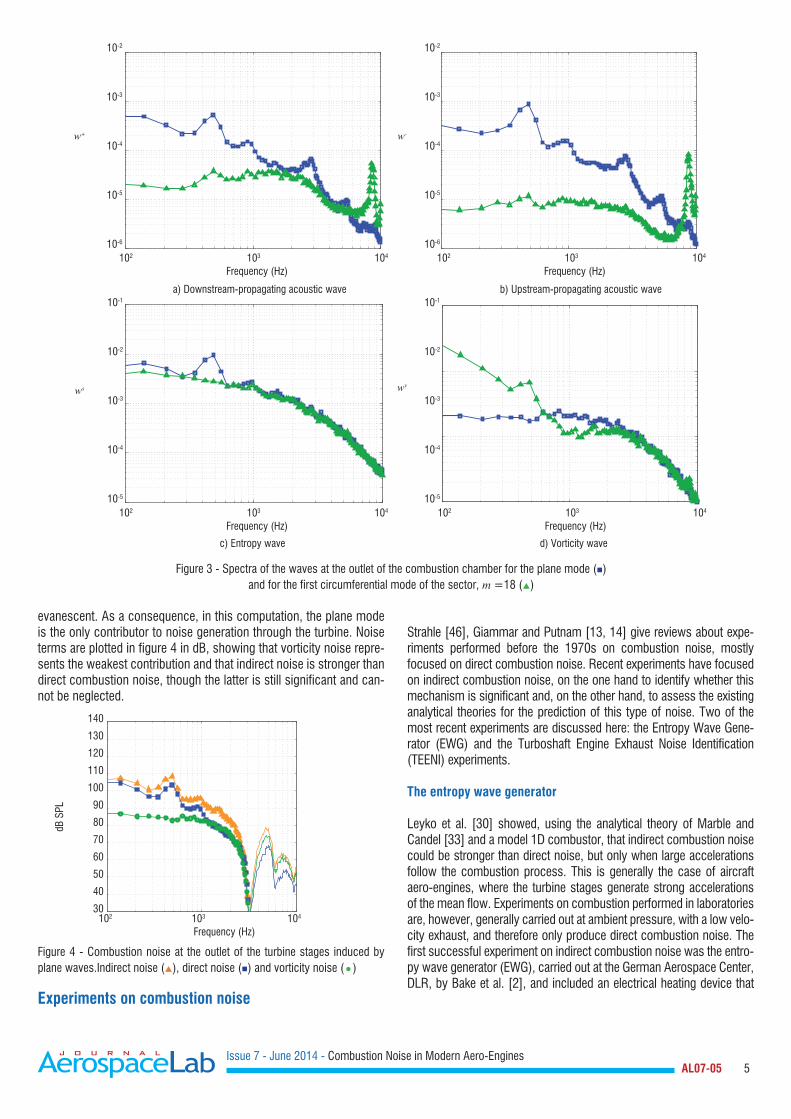
This hybrid method has been successfully applied in several state-of-the-art industrial aero-engines. The results of one of such simu-lations are presented here as an example. The LES simulations of the combustion chamber are performed on a single sector, using the unstructured compressible reactive code AVBP [42]. The waves at the outlet of the combustion chamber (acoustic, entropy and vor-ticity) are plotted in figure 3. It can be seen that the acoustic waves (figures 3(a) and 3(b)) are mainly longitudinal. It should be noted that, since the LES simulation is performed on a single sector, the low-order circumferential modes cannot be computed and only the plane mode will be taken into account. The circumferential mode in figure 3 corresponds to the first multiple of the number of sectors (m =18).
Using the analytical methods of Cumpsty and Marble [8], CHORUS is able to propagate these waves through the turbine stages and com-pute, on the one hand, direct combustion noise generated by acous-tic waves and, on the other hand, the contribution from entropy and vorticity waves in indirect combustion noise. Below 8400 Hz, the azimuthal mode, visible at the outlet of the chamber in figure 3, is
Issue 7 - June 2014 - Combustion Noise in Modern Aero-Engines AL07-05 5
evanescent. As a consequence, in this computation, the plane mode is the only contributor to noise generation through the turbine. Noise terms are plotted in figure 4 in dB, showing that vorticity noise repre-sents the weakest contribution and that indirect noise is stronger than direct combustion noise, though the latter is still significant and can-not be neglected.
102 103 104
Frequency (Hz)
140
130
120
110
100
90
80
70
60
50
40
30
dB S
PL
Figure 4 - Combustion noise at the outlet of the turbine stages induced by plane waves.Indirect noise (), direct noise () and vorticity noise (•)
Experiments on combustion noise
Strahle [46], Giammar and Putnam [13, 14] give reviews about expe-riments performed before the 1970s on combustion noise, mostly focused on direct combustion noise. Recent experiments have focused on indirect combustion noise, on the one hand to identify whether this mechanism is significant and, on the other hand, to assess the existing analytical theories for the prediction of this type of noise. Two of the most recent experiments are discussed here: the Entropy Wave Gene-rator (EWG) and the Turboshaft Engine Exhaust Noise Identification (TEENI) experiments.
The entropy wave generator
Leyko et al. [30] showed, using the analytical theory of Marble and Candel [33] and a model 1D combustor, that indirect combustion noise could be stronger than direct noise, but only when large accelerations follow the combustion process. This is generally the case of aircraft aero-engines, where the turbine stages generate strong accelerations of the mean flow. Experiments on combustion performed in laboratories are, however, generally carried out at ambient pressure, with a low velo-city exhaust, and therefore only produce direct combustion noise. The first successful experiment on indirect combustion noise was the entro-py wave generator (EWG), carried out at the German Aerospace Center, DLR, by Bake et al. [2], and included an electrical heating device that
102 103 104
Frequency (Hz) 102 103 104
Frequency (Hz)
102 103 104
Frequency (Hz) 102 103 104
Frequency (Hz)
10-2
10-3
10-4
10-5
10-6
10-2
10-3
10-4
10-5
10-6
10-1
10-2
10-3
10-4
10-5
10-1
10-2
10-3
10-4
10-5
ws wv
w+ w-
a) Downstream-propagating acoustic wave
c) Entropy wave
b) Upstream-propagating acoustic wave
d) Vorticity wave
Figure 3 - Spectra of the waves at the outlet of the combustion chamber for the plane mode () and for the first circumferential mode of the sector, m =18 ()

Issue 7 - June 2014 - Combustion Noise in Modern Aero-Engines AL07-05 6
modeled the combustion process, followed by a convergent-divergent nozzle, allowing both subsonic and supersonic flows with a shock wave. Figure 5 shows a sketch of the experimental set-up, where the heating device and the convergent-divergent nozzle are shown. Table 1 presents the main geometrical parameters.
Inlet
Mics250 250
l13
100
OutletElectrical heating
Figure 5 - Diagram of the Entropy Wave Generator experimental set-up (lengths are given in mm). Figure reproduced from Leyko [27]
Convergentlength
Divergentlength
Throatdiameter
Inletdiameter
Exitdiameter
13 mm 250 mm 7.5 mm 30 mm 40 mm
Table 1 - Main geometrical characteristics of the EWG nozzle
The flow through the nozzle could be either subsonic or supersonic with a shock wave, depending on the mass flow rate. Table 2 shows the main physical parameters of the EWG experiment for the supersonic case. When the heating device is triggered, it generates a temperature pulse shown in figure 6, due to the unsteady heat release. This unstea-dy heat release generates an entropy wave and an acoustic wave, as explained in § "The two combustion noise generation mechanisms".
Plenum pressure Outlet pressure Inlet Mach
117000 Pa 100800 Pa 0:037
Outlet Mach Pulse duration, Pulse amplitude
0.023 100 ms 9 K
Table 2 - Main physical parameters of the EWG experiment in the supersonic case with a shock wave.
0 0.05 0.10 0.15 0.20 0.25t(s)
60
40
20
0
-20
-40
P'(P
a)
Figure 6 - Temperature pulse of the EWG in the supersonic case: experimental data ( — ) and numerical simulations (---) [31]
The experimental configuration has been studied for both the super-sonic case [31] and the subsonic case [11, 15, 19, 29, 28]. For the supersonic case, the analytical model of Marble and Candel [33] was shown to correctly predict the entropy noise generated by the configu-ration, taking into account the propagation of waves through the nozzle and the interaction of these acoustic and entropy waves with the shock wave present in the divergent section [29, 31]. It was also shown that
the main noise source in this case was the indirect mechanism. The pressure waves at the outlet of the EWG are shown in figure 7, showing a perfect agreement between numerical simulations and analytical methods. The slight disagreement with the experimental data is pro-bably caused by the uncertainties on boundary conditions, as explained by Leyko et al. [31].
Howe [19] showed that, for the subsonic case, the large levels of pres-sure fluctuations measured experimentally at the outlet of the nozzle could not be attributed to the indirect mechanism. Duran et al. [11] showed that the heating device generated acoustic waves, due to the density fluctuations induced by the fluctuating heat release. These acoustic waves generated a direct noise contribution that was shown to be larger than the indirect source.
The EWG will be followed by the HAT nozzle with high pulsation ener-gies, within the scope of the RECORD project funded by the Seventh Framework Program (FP7) of the European Commission. In this experi-ment, other aspects of indirect noise will be studied, such as non-linear effects, since entropy waves generated in real combustion chambers are expected to be large enough to present non-linear effects. This ex-periment will study the generation of noise by large-amplitude entropy waves and how the dissipation of entropy waves should be taken into account. The RECORD project will also focus on the understanding of core noise generation and transmission mechanisms, in real combus-tors and academic burners, using LES simulations coupled with low-order models and validated with experimental data.
0 0.05 0.10 0.15 0.20 0.25t(s)
10
8
6
4
2
0
T'(K
)
a) Comparison between experimental data (—) and numerical simulations ( --- )
0 0.05 0.10 0.15 0.20 0.25t(s)
60
40
20
0
-20
-40
P'(P
a)
(b) Comparison between numerical simulations ( --- ) and analytical methods ( - + - )Figure 7 - Indirect noise measured at the outlet of the EWG nozzle in the supersonic case [31]TEENI: Full-scale combustion noise measurements

Issue 7 - June 2014 - Combustion Noise in Modern Aero-Engines AL07-05 7
The TEENI program (Turboshaft Engine Exhaust Noise Identification) funded by the FP7 of the European Commission is focused on tur-boshaft engine noise, where jet-noise is negligible since the outlet flow speed is very low. The main aim of the project is to determine which of the other noise sources (turbine, combustion noise, etc.) is dominant in such engines. To do so, the objectives of the program are to: • develop and test sensors that will allow the measurement of acoustic pressure and temperature fluctuations and are resistant to the engine environment (particularly high-temperatures); • discriminate the origin of the sound field generated at the outlet of the turboshaft; • understand the propagation of broadband noise through turbine blade rows; • develop noise-source breakdown techniques, in order to locate the origin of the noise inside the engine.
Though the purpose of the project has a very wide scope, there is a particular interest in combustion noise identification. Experimental iden-tification of other sources is relatively easy compared with combustion noise: turbine blades, for example, can be mounted in an experimental rig and tested individually; on the contrary, since combustion noise is generated both in the combustion chamber and caused by the propaga-tion of entropy waves through turbine blades (generating indirect com-bustion noise), any aim at identifying combustion noise experimentally must be done in a complete engine test-rig, where other noise sources will add up interfering with combustion noise. Traditionally, in turbo-fan engines, combustion noise was measured indirectly by subtracting the
individually tested noise contributions (such as compressor, turbine, fan and jet noise) from the noise of the complete test-rig, yielding what was usually known as ‘excess noise’, ‘excess broadband noise’ or sometimes simply ‘core noise’. One of the goals of TEENI is to develop sensors and experimental procedures that will allow combustion noise to be identified accurately in a full scale aero-engine, performing cross-correlations of the pressure signal at the outlet with the pressure and temperature signals measured inside the combustion chamber.
Combustionchamber
Temperature andpressure sensor
30 pressuresensors along the
circumference
High pressureturbine
Free turbines(FT1 and FT2)
Pressuresensors
CompressorsOulet nozzle
Figure 8 - Diagram of the TEENI experimental set-up
Figure 9 - PSD of pressure fluctuations (—) measured in the outlet nozzle and coherent PSD of pressure fluctuations correlated between different locations within the engine and this reference pressure probe using the three-sensor techniques (—).
0 500 1000 1500 2000 2500 3000 3500 4000frequency (Hz)
0 500 1000 1500 2000 2500 3000 3500 4000frequency (Hz)
0 500 1000 1500 2000 2500 3000 3500 4000frequency (Hz)
(a) Combustion Chamber
10dB 10dB
10dB
PSD
(Pa2 /H
z)
PSD
(Pa2 /H
z)
PSD
(Pa2 /H
z)
(b) High Pressure Turbine
(c) Free turbine

Issue 7 - June 2014 - Combustion Noise in Modern Aero-Engines AL07-05 8
The experimental set-up consists of an entire Turbomeca engine, modi-fied to install the instrumentation. A diagram of the configuration is shown in figure 8. Probes have been developed by the DLR to be adapted to the engine environment. Each pressure probe is a flush-mounted pin-hole with a remote microphone placed perpendicular to a semi-infinite tube, limiting standing wave effects [37]. To prevent microphone effects from hot combustion products, a cooling system injects a controlled air flow rate through the tube [12]. Temperature sensors were based on a twin thermocouple design, in order to be able to detect fluctuations of up to 700Hz. Since the project is aimed at identifying different noise sources, these sensors are placed in the combustion chamber, the high pressure turbine, the two free turbines and the exhaust nozzle. In total, 36 acous-tic internal probes, 9 twin thermocouples and 18 far-field microphones were used. The harsh conditions, especially in the combustion cham-ber, required an original probe design and a cooling system, ensuring high-quality measurements.
Due to broadband nature of combustion noise, characterization of this contribution in the core noise requires broadband-noise breakdown techniques. In particular, it is possible to extract coherent power spec-tral density (PSD) of pressure fluctuations between three probes, using the three-sensor technique [54, 43, 6, 26] applied between two probes within the engine and a reference probe in the outlet nozzle, or in the far-field. Results are plotted in figures 9 and 10.
A narrowband coherent PSD is visible in figure 9(a) in the frequency interval [200Hz, 400Hz], between the combustion chamber and the
outlet nozzle, which corresponds to the direct combustion noise, unlike the far-field reference microphone (figure 10(a)). On the other hand, the three-sensor technique applied in the high pressure turbine shows a glo-bal increase of coherent PSD in the interval [200 Hz, 1000Hz] in figures 9(b) and 10(b). However, the lack of noticeable spectral contents in temperature fluctuations in this frequency range does not allow indirect combustion noise to be clearly identified as major contributor. Finally, the three-sensor technique does not show an important contribution of the free turbine stages in the generation of coherent broadband PSD below 4000 Hz, as seen in figures 9(c) and 10(c).
Conclusions and perspectives
Combustion noise is a complex phenomenon involving at the same time combustion mechanisms, turbulence, chemistry, acoustics and turbo-machinery. This noise source is not the main one in industrial aero-en-gines, though it has been shown to have a direct impact on helicopter certification levels. Its influence increases as other noise sources are reduced. At the same time, new low-NOx emission combustion cham-bers have been found to generate more combustion noise than their predecessors. For this reason, research is being carried out in order to predict this noise source and to develop noise-reduction methods. The dificulty of predicting combustion noise lies in its nature: direct noise is generated in the combustion chamber, but can be attenuated when propagating through turbine stages, while indirect noise is due to the acceleration of the entropy waves (generated in the combustion
Figure 10 - Acoustic PSD (—) measured in the direction of maximum acoustic radiation at the far-field and coherent PSD of pressure fluctuations correlated between different locations within the engine and this reference microphone using the three-sensor techniques (—).
0 500 1000 1500 2000 2500 3000 3500 4000frequency (Hz)
0 500 1000 1500 2000 2500 3000 3500 4000frequency (Hz)
0 500 1000 1500 2000 2500 3000 3500 4000frequency (Hz)
(a) Combustion Chamber
10dB 10dB
10dB
PSD
(Pa2 /H
z)
PSD
(Pa2 /H
z)
PSD
(Pa2 /H
z) (b) High Pressure Turbine
(c) Free turbine

Issue 7 - June 2014 - Combustion Noise in Modern Aero-Engines AL07-05 9
chamber) when propagating through the blades. In this article, a hybrid method (CHORUS) is presented, in which large eddy simulations of the combustion chamber are combined with analytical solutions for the propagation of waves through turbine blades, in order to obtain the noise (direct and indirect) at the outlet of the aero-engine. The analytical method is based on strong assumptions, which must be validated with experimental data. With this purpose, the EWG experiment was per-formed, showing first the importance of indirect noise and allowing an experimental comparison with the analytical methods.
The TEENI experiment is also a good example of the progress being made by the combustion noise community. In this case, a complete turboshaft engine has been mounted and instrumented with state-of-the-art pressure and temperature probes, in order to identify combus-tion noise (and other sources) through detailed signal post-processing. These noise identification techniques are of great importance, since they allow the most significant noise sources to be identified. The objective is to later apply noise reduction technologies, such as acoustic liners, appropriately focused on the dominant source to obtain the largest pos-sible noise reduction.
In the near future, the RECORD project (funded by the 7th FP of the Euro-pean Commission) will further investigate combustion noise. In particu-lar, the first part of the RECORD project will study the influence of the pulse nature on the generation of waves. At the same time, the RECORD project will focus on the noise sources inside experimental combustion
chambers at high pressure (with an outlet nozzle), which will be then available for validation purposes, and on the propagation of acoustic and entropy waves through a real turbine stage, in order to validate the 2D analytical models
Nomenclature
c Sound velocity Vorticity
cp Specific heat at constant pressure Density
cv Specific heat at constant volume e Excess density
Jk Diffusion flux Ratio of specific heats
P Pressure ij Shear stress tensor
Q·
Unsteady heat release T· Heat release per unit volume
r Specific gas constant Pulsation
s Entropy t Total state
t Time i Inlet
T Temperature o Outlet
u Velocity vector ' Fluctuation
w Wave Far-field value
x Axial component + Upstream
- Downstream
Acknowledgements
The authors would like to thank Nancy Kings and Friedrich Bake from the DLR for providing the EWG data and fruitful inputs. This work was partly funded by Snecma and Turbomeca.
References
[1] C. BAILLY, C. BOGEY, S. CANDEL - Modelling of Sound Generation by Turbulent Reacting Flows. International Journal of Aeroacoustics, 9(4):461-490, 2010.[2] F. BAKE, C. RICHTER, B. MUHLBAUER, N. KINGS, I. ROHLE, F. THIELE, B. NOLL - The Entropy Wave Generator (EWG): a Reference Case on Entropy Noise. J. Sound Vib. , pages 574-598, 2009.[3] T.-D. BUTLER, P.-J. O'ROURKE - A Numerical Method for Two-Dimensional Unsteady Reacting Flows. Proc. Combust. Inst. , 16(1):1503-1515, 1977.[4] S. CANDEL - Acoustic Transmission and Reection by a Shear Discontinuity Separating Hot and Cold Regions. J. Sound Vib. , 24:87-91, 1972.[5] H. CHIU, M. SUMMERFIELD - Theory of Combustion Noise. Acta Astronautica , 1: 967-984, 1974.[6] J.-Y. CHUNG - Rejection of Flow Noise Using a Coherence Function Method. Journal of the Acoustical Society of America, 62(2):388-395, 1977.[7] O. COLIN, F. DUCROS, D. VEYNANTE, T. POINSOT - A Thickened Flame Model for Large Eddy Simulations of Turbulent Premixed Combustion. Phys. Fluids , 12(7):1843-1863, 2000.[8] N.-A. CUMPSTY, F.-E. MARBLE - The Interaction of Entropy Fluctuations with Turbine Blade Rows; a Mechanism of Turbojet Engine Noise. Proc. R. Soc. Lond. A , 357:323-344, 1977.[9] A. DOWLING, G.-J. BLOXSIDGE, N. HOOPER, P.-J. LANGHORNE - Active Control of Reheat Buzz. AIAA Journal, 26(7):783-790, July 1988. ISSN 0001-1452. doi: 10.2514/3.9970. URL http://doi.aiaa.org/10.2514/3.9970.[10] I. DURAN, S. MOREAU - Solution of the Quasi One-Dimensional Linearized Euler Equations Using Flow Invariants and the Magnus Expansion. Journal of Fluid Mechanics, 723: 190-231, May 2013.[11] I. DURAN, S. MOREAU, T. POINSOT - Analytical and Numerical Study of Combustion Noise Through a Subsonic Nozzle. AIAA Journal, 51(1):42-52, 2013.[12] U.-M.-F. BAKE, I. ROEHLE - Investigation of Entropy Noise in Aero-Engine Combustors. Proceedings of the ASME Turbo Expo 2006, 2006.[13] R.-D. GIAMMAR, A.-A. PUTNAM - Combustion Roar of Turbulent Diffusion Flames. Journal of Engineering for Power, 92(2):157-165, April 1970.[14] R.-D. GIAMMAR, A.-A. PUTNAM - Combustion Roar of Premix Burners, Singly and in Pairs. Combust. Flame , 18:435-438, 1972.[15] A. GIAUQUE, M. HUET, F. CLERO - Analytical Analysis of Indirect Combustion Noise in Subcritical Nozzles. J. Eng. Gas Turbines Power, 134(11):111202, 2012.[16] C.-S. GOH, A.-S. MORGANS - Phase Prediction of the Response of Choked Nozzles to Entropy and Acoustic Disturbances. Journal of Sound and Vibration, pages 1-15, June 2011. ISSN 0022460X. doi: 10.1016/j.jsv.2011.05.016. URL http://linkinghub. elsevier.com/retrieve/pii/S0022460X11004019.[17] H. HASSAN - Scaling of Combustion Generated Noise. J. Fluid Mech. , 66:445-453, 1974.

Issue 7 - June 2014 - Combustion Noise in Modern Aero-Engines AL07-05 10
[18] M.-S. HOWE - The Generation of Sound by Aerodynamic Sources in an Homogeneous Steady Flow. J. Fluid Mech. , 67(3):597-610, 1975.[19] M.-S. HOWE - Indirect Combustion Noise. J. Fluid Mech. , 659:267-288, 2010.[20] M. HUET, A. GIAUCQUE - A Nonlinear Model for Indirect Combustion Noise Through a Compact Nozzle. J. Fluid Mech. , 733:268-301, 2013.[21] M. IHME, H. PITSCH - On the Generation of Direct Combustion Noise in Turbulent Non-Premixed Flames. International Journal of Aeroacoustics, 11(1):25-78, 2012. [22] M. IHME, D. BODONY, H. PITSCH - Towards the Prediction of Combustion-Generated Noise in Non-Premixed Turbulent Flames Using Large-Eddy Simulation. CTR, pages 311-323, 2005. [23] A.-R. KERSTEIN - A linear Eddy Model of Turbulent Scalar Transport and Mixing. Combust. Sci. Tech. , 60:391, 1988.[24] M. KOSTKA, H. PITSCH - Direct Approach to the Prediction of Indirect Combustion Noise. Technical report, 2010. [25] S. KOTAKE - On Combustion Noise Related to Chemical Reactions. J. Sound Vib. , 42: 399-410, 1975.[26] E.-A. KREJSA - Combustion Noise from Gas Turbine Aircraft Engines Measurement of Far-Field Levels. Technical Report NASA Technical Report 88971, NASA, 1987.[27] M. LEYKO - Mise en œuvre et analyse de calculs aéroacoustiques de type SGE pour la prévision du bruit de chambres de combustion aéronautiques. Phd thesis, INP Toulouse, 2010.[28] M. LEYKO, F. NICOUD, S. MOREAU, T. POINSOT - Numerical and Analytical Investigation of the Indirect Noise in a Nozzle. Proc. of the Summer Program, pages 343-354, Center for Turbulence Research, NASA AMES, Stanford University, USA, 2008.[29] M. LEYKO, S. MOREAU, F. NICOUD, T. POINSOT - Numerical and Analytical Investigation of the Indirect Combustion Noise in a Nozzle. Comptes Rendus Mécanique, 337(6-7): 415-425, 2009a.[30] M. LEYKO, F. NICOUD, T. POINSOT - Comparison of Direct and Indirect Combustion Noise Mechanisms in a Model Combustor. AIAA Journal , 47(11):2709-2716, 2009b.[31] M. LEYKO, S. MOREAU, F. NICOUD, T. POINSOT - Numerical and Analytical Modeling of Entropy Noise in a Supersonic Nozzle with a Shock. J. Sound Vib. , 330(16, 1): 3944-3958, 2011.[32] M.-J. LIGHTHILL - On Sound Generated Aerodynamically. i. general theory. Proc. R. Soc. Lond. A , Mathematical and Physical Sciences, 211(1107):564-587, 1952.[33] F.-E. MARBLE, S. CANDEL - Acoustic Disturbances from Gas Nonuniformities Convected Through a Nozzle. J. Sound Vib. , 55:225-243, 1977.[34] M. MATALON, B.-J. MATKOWSKY - Flames as Gas Dynamic Discontinuities. J. Fluid Mech. , 124:239, 1982.[35] W. MOASE, M. BREAR, C. MANZIE - The Forced Response of Choked Nozzles and Supersonic Diffusers. Journal of Fluid Mechanics, 585:281-304, 2007. ISSN 0022- 1120. doi: 10.1017/S0022112007006647. URL http://journals.cambridge.org/ abstract\_S0022112007006647.[36] M. MUTHUKRISHNAN, W. STRAHLE, D. NEALE - Separation of Hydrodynamic, Entropy, and Combustion Noise in a Gas Turbine Combustor. AIAA Journal, 16(4):320-327, 1978.[37] S. PERENNES, M. ROGER - Aerodynamic Noise of a Two-Dimensional Wing with High-Lift Devices. AIAA Journal, 1998.[38] O.-M. PHILLIPS - On the Generation of Sound by Supersonic Turbulent Shear Layers. J. Fluid Mech. , 9:1-28, 1960.[39] G.-F. PICKETT - Core Engine Noise Due to Temperature Fluctuations Convecting Through Turbine Blade Rows. 2nd AIAA Aeroacoustics Conference - AIAA 1975-528, 1975.[40] T. POINSOT, D. VEYNANTE - Theoretical and Numerical Combustion. Third Edition (www.cerfacs.fr/elearning), 2011.[41] R. RAJARAM, T. LIEUWEN - Acoustic Radiation from Turbulent Premixed Flames. Journal of Fluid Mechanics, 637:357-385, 2009. ISSN 0022-1120. [42] T. SCHONFELD, M. RUDGYARD - Steady and Unsteady Flows Simulations Using the Hybrid Flow Solver AVBP. AIAA Journal , 37(11):1378-1385, 1999.[43] B.-N. SHIVASHANKARA - Gas Turbine Core Noise Source Isolation by Internal-to-Far-Field Correlations. J. Aircraft , 15(9):597-600, 1978.[44] Y. SINAI - The Generation of Combustion Noise by Chemical Inhomogeneities in Steady, Low-Mach-Number Duct Flows. Journal of Fluid Mechanics, 99, 1980. [45] S. STOW, A. DOWLING, T. HYNES - Reflection of Circumferential Modes in a Choked Nozzle. Journal of Fluid Mechanics, 467:215-239, 2002. ISSN 0022-1120. doi: 10.1017/S0022112002001428. [46] W.-C. STRAHLE - On Combustion Generated Noise. J. Fluid Mech. , 49:399-414, 1971.[47] W.-C. STRAHLE - Some Results in Combustion Generated Noise. J. Sound Vib. , 23(1): 113-125, 1972.[48] N. SWAMINATHAN, G. XU, A. P. DOWLING, R. BALACHANDRAN - Heat Release Rate Correlation and Combustion Noise in Premixed Flames. Journal of Fluid Mechanics, 681:80-115, 2011. ISSN 0022-1120. doi: 10.1017/jfm.2011.232. [49] M. TALEI, M. J. BREAR, E. R. HAWKES - Sound Generation by Laminar Premixed Flame Annihilation. Journal of Fluid Mechanics, 679:194-218, Apr. 2011. ISSN 0022-1120. doi: 10.1017/jfm.2011.131. [50] C.-K. TAM, S.-A. PARRISH, J. XU, B. SCHUSTER - Indirect Combustion Noise of Auxiliary Power Units. AIAA Conference, number June, Colorado Springs, 2012.[51] C.-K. TAM, S.-A. PARRISH, J. XU, B. SCHUSTER - Indirect Combustion Noise of Auxiliary Power Units. Journal of Sound and Vibration, 332(17):4004-4020, Aug. 2013. ISSN 0022460X. doi: 10.1016/j.jsv.2012.11.013. URL http://linkinghub.elsevier.com/ retrieve/pii/S0022460X12008619.[52] H.-S. TSIEN - The Transfer Functions of Rocket Nozzles. J. American Rocket Society , 22 (3):139-143, 1952.[53] J.-E.-F. WILLIAMS, M. HOWE - The Generation of Sound by Density Inhomogeneities in Low Mach Number Nozzle Flows. Journal of Fluid Mechanics, 70(3):605-622, 1975. [54] P.-H. WIRSCHING, T.-L. PAEZ, K. ORTIZ - Random Vibrations : Theory and Practice. Dover publications, 2006.[55] P. WOLF, G. STAFFELBACH, R. BALAKRISHNAN, A. ROUX, T. POINSOT - Azimuthal Instabilities in Annular Combustion Chambers. In N. A. U. Center for Turbulence Research, editor, Proc. of the Summer Program , pages 259-269, 2010.
Issue 7 - June 2014 - Combustion Noise in Modern Aero-Engines AL07-05 11
AUTHORS
Ignacio Duran graduated from Universidad Politécnica de Ma-drid (UPM) and Ecole Nationale Supérieure d’Ingénieurs de Constructions Aéronautiques (Ensica) in 2011 and received his Ph. D. Degree in Energetics in 2013. His Ph. D. thesis was fo-cused on the prediction of combustion noise in modern aero
engines combining Large Eddy Simulations and analytical methods at CER-FACS and financed by Snecma.
Stéphane MOREAU graduated from Ecole Nationale Supé-rieure d’Aéronautique de l’Espace (now Isae) in 1988 and re-ceived his PhD in Mechanical Engineering (with a minor in Ae-ronautics & Astronautics) from Stanford University in 1993. He joined the AC2 start-up on plasma propulsion in 1994. He then
worked in the Integration department at Snecma, Safran group in 1995. He then worked for Valeo, the Tier-1 automotive supplier on engine cooling fan systems, where he managed the research group from 1996 to 2008. He later joined the Mechanical Engineering faculty at Université de Sherbrooke in Qué-bec, Canada, where is now a full professor
Franck Nicoud graduated in 1990 from the National School of Engineering for Hydraulics, Electronics, Electrotechnics and Informatics in Toulouse (ENSEEIHT). He then received a Fel-lowship from the French Space Agency (Cnes) to do a PhD thesis at the French Aerospace Lab (Onera), under the gui-
dance of Prof. Ha Minh. After defending his experimental/numerical work about the prediction of heat transfers within solid rocket motors in 1993, he was hired by the European Center for Research and Advanced Training in Scientific Computing (Cerfacs) as a post-doctoral researcher. He became a senior scientist at Cerfacs in 1995 and participated in the development of Large Eddy Simulation tools for reacting compressible flows in complex geo-metries. He then accepted a research fellowship at the Center for Turbulence Research (CTR) of Stanford University and Nasa/Ames in 1998 and was ap-pointed Professor at University Montpellier in 2001. While his research acti-vity at Montpellier is now mainly focused on computational cardiovascular biomechanics and the development of the YALES2BIO solver, he is still wor-king in close connection with Cerfacs, addressing issues related to combus-tion noise, thermo-acoustic instabilities and wall modeling.
Thomas Livebardon obtained his engineering degree from Ensma (Ecole Nationale Supérieure de Mécanique et d’Aéro-technique) and his Master’s Degree in 2011. He is a PhD student working on the modeling of combustion noise in tur-boshaft engines at Cerfacs. This thesis is funded by TUR-
BOMECA.Éric Bouty: After a degree in lightning, acoustics and air condi-tioning, (Maîtrise de Sciences et Techniques, now ESIP) from Poitiers University, Éric Bouty graduated from Le Mans Univer-sity in Acoustics (DEA) in 1987. He joined Gaz de France as a research engineer and then Snecma in 1989. He worked main-
ly on fan noise, proposing innovative OGV designs. He participated in many European projects, including SILENCE(R), for which he acted as the Coordi-nator Technical Deputy. He has led the acoustic group of Turbomeca since 2006, with a recent focus on combustion noise.
Thierry Poinsot received his PhD thesis in heat transfer from Ecole Centrale Paris in 1983 and his Thèse d’Etat in combus-tion in 1987. He is a research director at CNRS, head of the CFD group at Cerfacs, senior research fellow at Stanford Uni-versity and a consultant for various companies. After his thesis
at Ecole Centrale Paris and after two years of post-doctoral work at Stanford, he started combustion activities at Cerfacs in 1992 and his group (60 per-sons in 2010) has produced a significant part of the recent research in the field of LES of turbulent combustion in gas turbines. He teaches numerical methods and combustion at many schools and universities (Ecole Centrale Paris, ENSEEIHT, Ensica, Supaero, UPS, Stanford, Von Karmann Institute, CEFRC Princeton and Beijing). He has authored more than 150 papers in refe-reed journals and 200 communications. He is the co-author of the textbook "Theoretical and numerical combustion" together with Dr D. Veynante and an associate editor of “Combustion and Flame”. He received the first Cray prize in 1993, the BMW prize in 2002, the Grand Prix of the French Academy in 2003 and an ERC advanced grant in 2013.
Acronyms
CHORUS (complete hybrid computation chain)EWG (Entropy Wave Generator)FP7 (Framework Program)HAT (Hot Acoustic Testrig)
LES (Large Eddy Simulations)PSD (Power Spectral Density)RANS (Reynolds-Averaged Navier-Stokes)TEENI (Turboshaft Engine Exhaust Noise Identification)