command list (array e) - lunar and planetary institute list (array e) ,.,. op 20 dati 8 march 197 2...
TRANSCRIPT
. n
~TM-930 D
Command List (Array E) ,.,. OP 20
DATI 8 March 197 2
This listing of command allocations is applicable to ALSEP Array E, with the following complement of experiments!
#1 Lunar Mass Spectrometer #2 Lunar Ejecta and Meteorites #3 Heat Flow #4 Lunar Surface Gravimeter #5 Lunar Seismic Profiling
Prepared by:~.£. f~. D. J. ~omas ·
Approved by:--~~ !)~ P'ithian · · ·
, .
. ')
~ ~DivlaiDn
Symbol
CD-32 CD-33 CD-34 CD-38 CD-39 CD-40 CD-41 CD-42 CD-5 CD-6 CD-7 CD-8 CD-43 CD-44
CD-47 ., CD-11
CD-12 CD-13 CD-14 CD-15 CD-16 CD-17
Command List (Array E)
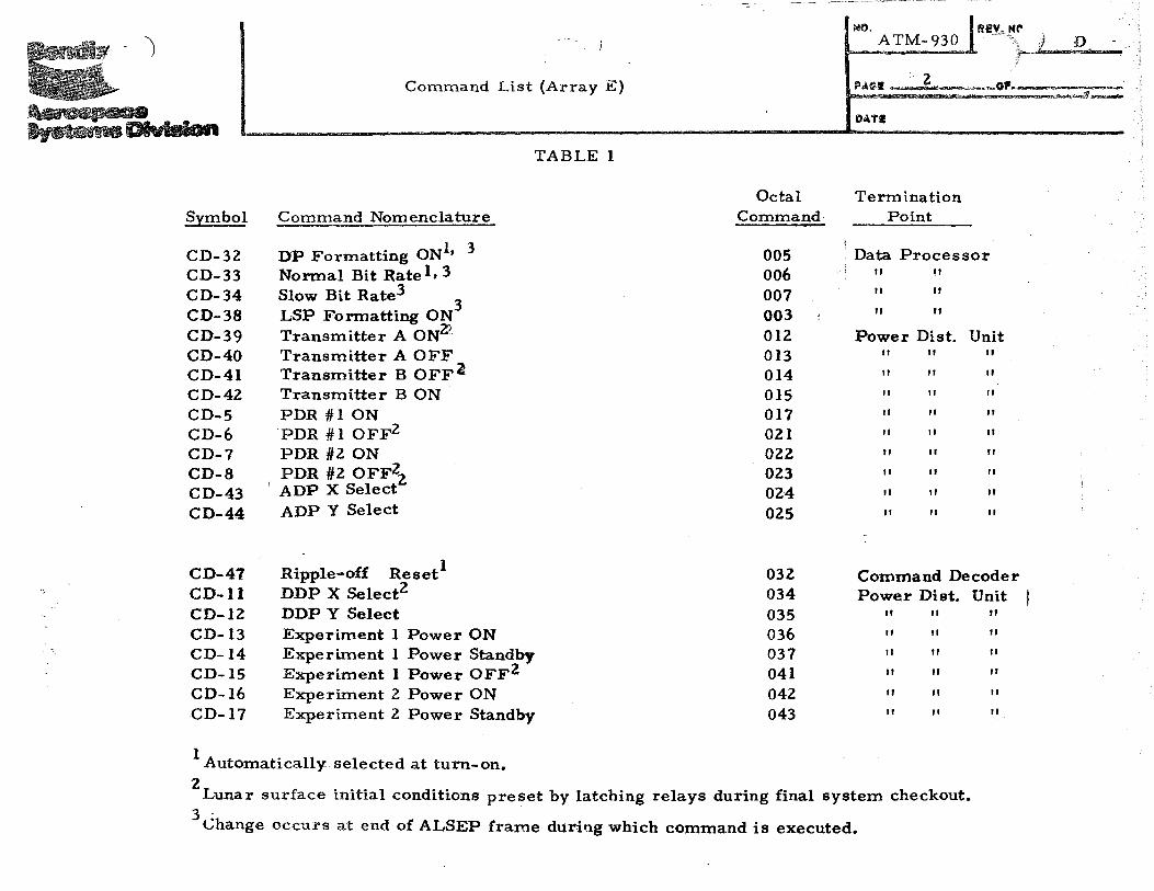
TABLE 1
Command Nomenclature
DP Formatting ON1• 3
Normal Bit Rate 1, 3 Slow Bit Rate3
3 LSP Fonnatting ON Transmitter A ONZ' Transmitter A OFF Transmitter B OFFa Transmitter B ON PDR #1 ON 'PDR #1 OFF2 PDR #2 ON PDR #2 OFF22.
' ADP X Select ADP Y Select
Ripple-off 1 Reset DDP X Select2 DDP Y Select Experiment 1 Power ON Experiment 1 Power Standby Experiment 1 Power OFF2 Experiment 2 Power ON Experiment 2 Power Standby
1 Automatically selected at turn-on.
Octal Comma~
005 006 007 003 1
012 013 014 015 017 021 022 023 024 025
032 034 035 036 037 041 042 043
MO. ATM-930 R~Y, .. ,~,... .;· R.,_·_
I '--~--I
. 2 . a.:A~I ;: : =---.c~~O'~-=
DATI
Termination Point
! Data Processor
'l II 11
II II
II II
Power Dist. Unit II II II
II II II
II II II
II II II
II II II
II II II
II II II
II II II
II II II
Command Decoder Power Dist. Unit
II II II
II " II
II II II
II II II
II II II
II II II
2Lunar surface initial conditions preset by latching relays during final system checkout.
3 Change occurs at end of ALSEP frame during which command is executed.
NO. ATM- 930 I~~~,"~,~-;r------
.Q
Command. List (A •• ay E) FAG!i
3
DATI
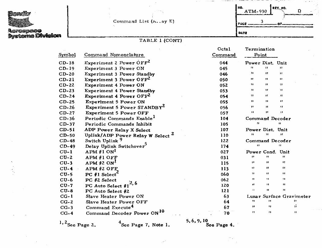
TABLE 1 (CONT)
Octal Termination Symbol Command Nomenclature Command Point
CD-18 Experiment 2 Power OFF2 044 Power Dist. Unit CD-19 Experiment 3 Power ON 045 II II II
CD-20 Experiment 3 Power Standby 046 II II II
CD-21 Experiment 3 Power 0 FF2 050 II II II
CD-22 Experiment 4 Power ON 052 II II II
CD-23 Experiment 4 Power Standby 053 II II II
CD-24 Experiment 4 Power OF~ 054 II II II
CD-25 Experiment 5 Power ON 055 II II II
CD-26 Experiment 5 Power STANDBY2 056 II II II
CD-27 Experiment 5 Power OFF 057 II II II
CD-36 Periodic Commands Enable 1 104 Command Decoder CD-37 Periodic Commands Inhibit 105 " " CD-51 ADP Power Relay X Select 107 Power Dist. Unit CD-50 Uplink/ADP Power Relay W Select 2 110 II II II
CD-48 Switch Uplink 9 5
122 Command Decoder CD-49 Delay Uplink Switchover 174 " " CU-1 APM #1 ONI 027 Power Cond. Unit CU-Z APM #1 OFF 031 II II " CU-3 APM /12 ON1 115 If If " CU-4 APM #Z OFF 113 " II " CU-5
. 2 060 II " II PC Ill Select
CU-6 PC /12. Select ;2 6
062 " II " CU-7 PC Auto Select /1 r ' 120 II II " CU-8 PC Auto Select /12 121 II If " CG-1 Slave Heater Power ON 63 Lunar Surface Gravimeter CG-2 Slave Heater Power OFF 64 " II II
CG-3 Command Execute4 67 If " " CG-4 Command Decoder Power ON 10 70 II " II
I 2 4 5, 6, 9, 10 ' See Page 2. See Page 7, Note 1. See Page 4.

NO. l RI!V. NO. ATM-930 ''"'\" D ~
Command List (.n ... ray E) FAUll! 4
GP
~ lh.ta~lldl. Dhtalon DATe
TABLE 1 (CONT)
Octal Termination Symbol Command Nomenclature Command Point
CG-5 Command Decoder Power OFF 71 II II
CG-6 Step Command Counter UP 7Z II II
CG-7 Step Command Counter DOWN 74 II II
CJ-17
LEAM Calibrate HIGH/ LOW (Periodic Command) Ill LEAM CJ-Z LEAM Mirror Cover Release llZ II
CJ-3 LEAM Sensor Cover Release 114 II
CJ-4 LEAM Heater ON/OFF/AUTO 117 It
4 See NOTE 1, page 7, for details of encoded LSG commands.
SA utomatic reset at turn-on ensures that CD-49 (Octal 174) is not effective until commanded. 6 : - .
7
This violates normal operating requirements. CU -8 (Octal 121) will be transmitted after satisfactory PC# 1 turn-on.
Also generated automatically within ALSEP as a pair of commands 3. 5 minutes apart, every 15.4 hours, Wl.less inhibited by execution of CD-37 (Oct~l 105).
9 Also generated automatically within ALSEP 7. 6 hours after turn-on, then every 61.8 hours, unless each potential switch is inhibited by the prior transmission of CD-49 (Octal 174). It is not possible to permanently inhibit the automatic generation of CD-48 (Octal 122) except by the regular transmit:Jsion of CD-49 at intervals not exceeding 61.8 hours.
10Transmission of command CG-4 will also clear the LSG command counter to 00000 (binary).
,_ ....... _
II
II
II

)
Symbol
CMf-1 8
CM-2 CM-3 CM-4 CM-5 CM-6 CM-7 CH-1 CH-2 CH-3 CH-4 CH-5 CH-6 CH-7 CH-8 CH-9
Command List (Array E)
Command Nomenclature
LMS Load Command # 1 LMS Load Command # 2 LMS Load Command #3 LMS Load Command #4 LMS Load Command #5 LMS Load Command #6 LMS Execute and Clear
TABLE 1 (CONT)
Normal (Gradient) Mode Select1
Low Conductivity Mode Select (Ring Source) High Conductivity Mode Select {Heat Pulse) HF Full Sequence Select! ·. HF Probe # 1 Sequence Select HF Probe #2 Sequence Select HF Subsequence #1 ·-, Command HF Subsequence #2 J Functions as shown HF Subsequence #3 in Note 3
8Encoding of the CM series is described in Note Z, page 9~·
Octal Command
123 124 125 127 132 133 134 135 136
1 140 141 142 143 144 145 146
.. it!IV,Nt" ""'·"·'"··\'\•\)), D ATM- i\)
~---------5 .
P'AGI! q.......__._oP-~ ..................... ·~
DATI
Termination Point
LMS Experiment II II
II II
II II
II II
II II
II II
Heat Flow Experiment II II II
II II II
II II II
II II II
II II II
II II II
II II II
" II II
) NO.
ATM-930 Rill""~" D-~\
'I I
Command List {Array E) 6 P'AGI! --·-·· -OP____..;..-
DATI
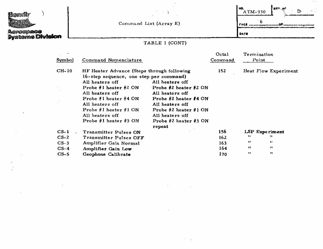
TABLE 1 (CONT)
Octal Termination Symbol Command Nomenclature Command Point
CH-10 HF Heater Advance (Steps through following 152 Heat Flow Experiment 16-step sequence, one step per command) All heaters off AU heaters off Probe # 1 heater #2 ON Probe liZ heater #2 ON All heaters off All heaters off Probe # 1 heater #4 ON Probe #2 heater #4 ON All heaters off All heaters off Probe # 1 heater # 1 ON Probe #2 heater# 1 ON All heaters off All heaters off Probe # 1 heater #3 ON Probe #2 heater #3 ON
repeat CS-1 ,,; Transmitter Pulses ON 156 LSP Experiment CS-2 Transmitter Pulses OFF 162 II II
CS-3 Amplifier Gain Normal 163 II II
CS-4 Amplifier Gain Low 164 II II
CS-5 Geophone Calibrate 170 II II

REi ... nve
ATM-930 D
Command List (Array E) PAGI
DATI!
Note I
LSG Commands
An expanded command capability is accomplished in the LSG experiment by decoding a 5-Stage, "Up-Down" Command Counter. Thirty of the possible thirty-two states of the counter are used to generate command functions. State of the Counter is read out through the telemetry link.
Three command line• are u•ed to step the command counter (up or down) and to generate a command execute function.
A list of all LSG experiment command counter states and the associated functional command assignments is provided below:
Command Symbol
CG-8 CG-9 CG-10 CG-11 CG-12 CG-13
Binary. Count
00001 00010 00011 00100 00101 00.110
Command Function
Read Shaft Encoder Mass Change Motor ON Bias In Bias Out Integrator, Normal Mode Integrator, Short Mode
Ofl

Symbol
CG-14 CG-15 CG-16 CG-17 CG-18 CG-19 CG-20 CG-21 CG-22 CG-23 CG-24 CG-25 CG-26 CG-27 CG-28 CG-29 CG-30 CG-31 CG-32 CG-33 CG-34 CG-35 CG-36 CG-37
ATM-930 ,-- D
Command List (Array E) ,.,. 8
DATI
LSG ELECTRONICS COMMAND ASSIGNMENT (CONT)
Binary Count
00111-01000 01001 01010 01011 01100 01101 01110 01111 10000 10001 10010 10011 10100 t0101 10110 10111 uooo 11001 11010 11011 11100 U101 11110
Command Function
Seismic Low Gain Seismic High Gain Sensor Beam Caged Sensor Beam Uncaged Coarse Screw Servo ON
Tilt, Mass Chg., Screw Servo & Press Trans. OF Pressure Tranducer ON Mass Change Increment Gross Slew Up/ Tilt Increment Up Gross Slew Down/ Tilt !ncr. Down Vernier -Slew Up Vernier Slew Down Fine Screw Servo ON North/ South Tilt Servo ON East/West Tilt Servo ON Temperature Relay #1 Temperature Relay #2 Temperature Relay #13 Temperature Relay #4 Temperature Relay #5 Temperature Relay fl:6 Temperature Reset Post Amp. Gain Increment Post Amp. Gain Reset
ATM-930 D
Command List (Array E) 9 OP Aaoapaca S,stema Dlvlelan DATI ~,.~- ~
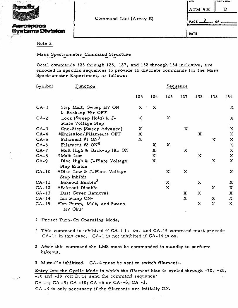
Note 2
Mass Spectrometer Command Structure
Octal commands 123 through 125, 127, and 132 through 134 inclusive, are encoded in specific sequences to provide 15 discrete commands for the Mass Spectrometer Experiment, as follows:
Symbol Function Sequence
123 124 125 127 132 133 134
CA-l Step Mult, Sweep HV ON X X & Back-up Htr OFF
CA-2 Lock (Sweep Hold) & J- X X Plate Voltage Step
CA-3 One-Step (Sweep Advance) X X CA-4 *Emission/ Filaments OFF X X CA-S Filament #1 ON3 X X CA-6 Filament #2 ON3 X X CA-7 Mult High & Back-up Htr ON X X CA-8 *Mult Low X X CA-9 Disc High & J-Plate Voltage X X
Step Enable CA-10 *Disc Low & J-Plate Voltage X X
Step Inhibit CA-ll Bakeout Enable2 X X CA-12 *Bakeout Disable X X CA-13 Dust Cover Removal X X CA-14 Ion Pump ON1 X X CA-15 *Ion Pump, Mult, and Sweep X X
HV OFF
* Preset Turn-On Operating Mode.
1 This command is inhibited if CA-l is on, and CA-15 command must precede CA-14 in this case. CA-l is not inhibited if CA-14 is on.
2 Mter this command the LMS must be commanded to standby to perform bake out.
3 Mutually inhibited. CA-4 must be sent to switch filaments.
Entry Into the Cyclic Mode in which the filament bias is cycled through -70, -25, -20 and -18 Volt D. Ct send the command sequence:
CA -4; CA -9; CA -10; CA. -_5o:;_ CA--6; CA -1. CA -4 is only necessary if the filaments are initially ON.
X
X
X X X X X X X
X
X X X X X

ATM-930 D
Command List (Array E) PAGI 10 OP
OATI
Note 3
Heat Flow Command Structure
Octal commands 144 through 146 are used to select subsets of the full heat flow measurement sequence as follows:
Command 144 selects a subset consisting of the four high sensitivity gradient measurements only.
Command 144 followed by command 145 selects a subset consisting of the four low sensitivity gradient measurements only.
Command 144 followed by command 146 selects a subset consisting of probe ambient temperature measurements only.
Command 145 followed by command 146 selects a subset consisting of thermocouple measurements only.

ftUo ICilY. ftUo
ATM 930 D Command List (Array E)
PAGI 11
DATI
Command Availability and Usage,and Test Commands
Command usage is summarized in Table 2, and is also displayed for all the 128 potential commands, which could be derived from the seven bit command word, in Table 3. The command functions shown in Table ~ are determined by the Command Decoder design; 104 commands are !
physically decoded, of which 79 are currently used to control the syst:em. I
i All25 spare command outputs are available at the Command Decoder connectors and 19 of these spares could be used without restriction. The remaining six spares have the following limitations:
(a) Unless inhibited, Octal Commands 065 and 131 are pulsed, automatically once every 15. 4 hours, in addition to any grounq transmissions. (See Octal Command 111, Page 4.) I
(b) Octal Commands 157, 167, 173 and 176 are primarily inte:nded to be test commands (see below). They will not be used for system control until all other spares have been used. i
I All tlle spare outputs, except those for Octal Commands 011, 033 andj 106, are rise- and fall-time controlled to between 2 microseconds and 10 microseconds.
Test commands are the fourteen Octal numbers which in their binary equivalents have only one 111 or one '0', in all the possible positions. They can be t:ransmitted, as required, to diagnose possible faults in the parity check and CVW circuits. Since most of the test commands are not physically decoded, and the four that are decoded are not used, there is no possibility of a test command in normal fault-free operation causing a system status change.
A TM- 93 0 l ~- ·;··-· Command List (Array E) PAGI 12
DATI
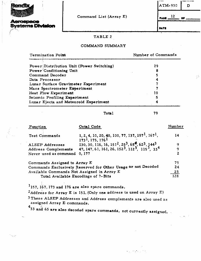
TABLE 2
COMMAND SUMMARY
Termination Point N~ber of Commands
Power Distribution Unit (Power Switching) Power Conditioning Unit Command Decoder
I
Data Processor Lunar Surface Gravimeter Experiment Mass Spectrometer E:Xperiment Heat Flow Experiment Seismic Profiling Experiment Lunar Ejecta and Meteoroid Experiment
Total
I
Function Octal Code
29 8 5 4 7 7
10 5 4
79
! :
Test Commands 1, 2, 4, 10, 20, 40, 100,77, 137, 157 1, 1671, 1731, 175, 1761 ;.
ALSEP Addresses Address Complements Never used as command
130, 30, 116, 16, 1512, 253, 65 .. 1, 623, 1443 47, 147,61, 161,26, 1523, u2l, 115 3, 334
0, 177
Commands Assigned to Array E Commands Exclusively ~eserved for Other Usage or not Decoded Available Commands Not Assigned in Array E
Total Available Encodings of 7- Bits
1157, 167, 173 and 176 are also spare eommands.
2Addr~ss for Array E is 151. (Only one address is used on Array E)
3 These ALSEP Addresses and Address complements are also used as assigned Array E cornmands.
4 .!,
33 and 65 are also decoded spare commands, not currently assigned •
l •' .. .
Number
14
9 9 2
79 24 25
128
) ) .Me). J ~ . .,,~ ... ,.
ATM-930 ,,,,, ·: D
Command List \- ray E) PAOli 13 OP·-----
DATI
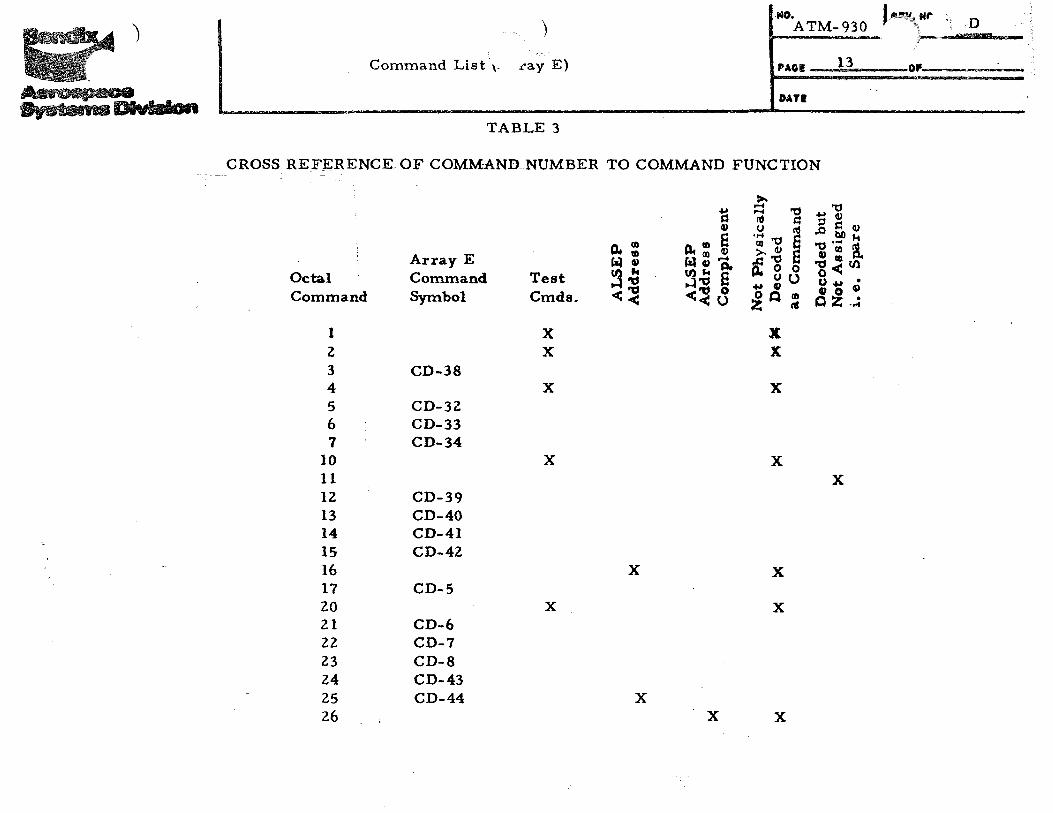
TABLE 3
CROSS REFERENCE OF COMMAND NUMBER TO COMMAND FUNCTION
Octal Command
1 z 3 4 5 6 7
10
Array E Command Symbol
CD-38
CD-3Z CD-33 CD-34
Test Cmds.
X X
X
X
ll.: ~ Q)
~~ <~
~ Q)
e " ., aJ ~co~ Czl G t:l. (I)"' E .,.l'tl 0
<~u
~ ~ 'tl ~ ~
..... nS co 'tl c >. aJ j;i
*'tiE ... 0 0 ... ~u ~Q=
X X
X
X
'tl .... aJ ~ d aJ
,.0 bO k 'tl·u; a CD.,Ul '0< 0 • 0 .... aJ Cl) zo • Q ....
11 X lZ CD-39 13 CD-40 14 CD-41 15 16 17 zo 21 2Z 23 24 25 26
CD-4Z
CD-5
CD-6 CD-7 CD-8 CD-43 CD-44
X X
X X
X X X

-;r.-'
.. r ~-\,"
'tl·' . " ..... ~·
)
Octal Command
27 3(} 31 32 33 34 35 36 37 40 41 42 43 44 45 46 47 50 51 52 53 54 55 56
)
Command List (Array E)
TABLE 3 (CONT)
Array E Command Symbol
CU-1
CU-Z CD-47
CD-11 CD-12 CD-13 CD-14
CD-15 CD-16 CD-17 CD-18 CD-19 CD-20
CD-21
CD-22 CD-23 CD-24 CD-25 CD-26
Test Cmds.
X
fl. {I) fa;l: tl)k ~'tJ
<~
X
NO. ATM-930
1'0
Rf~f~O.• D "\ .... '\
i :;._ ..
14 PAGII -- --·· --OP
.. s= Q)
e n !II Q) l"'t{l) ..... C:iiG>Il. U)ke ~ 'tJ 0 <~u
X
DATI
~ ..... ~ '8
·;;; "g a ~'8 a Jl. ~ 0 .uQt> ~ ro cf
X
X
X X
X
.-"0 =' ~ G) .a bO k
'"d .... "' G) Ul ll. '"dflltJl o< u ~ G) Q) 0
Q s= • ..;
X

) NO.
ATM-~30 IIEY.NO. 0
""''''~';;~
~ )
lS PAGII , -OP.~ Command List (Arr3.y E) ___.
OAT I
TABLE 3 (CONT)
~ ~ ~ ~ ~"" Q u ::s~ 4»
~ ~ i "E.,~ ,Q bll ... ll4 10
., .... , ~CII
Array E ~Ill S!af-88 .,~en
~~ 0< Octal Command Test "CC S ~u u.,.v Command Symbol Cmds.
ct;"' <"' 0 ~ ~ ~· < <o nt ....
57 CD-27 60 CU-5 61 X X 62 . CU-6 X 63 ' CG-1 64 CG-2 65 I X X 66 X 67 CG-3 70 CG-4 71 CG-5 72 CG-6 73 X 74 CG-7 75 X 76 X 77 X X
100 X X 101 X 102 X
103 X
104 CD-36

') )
Command List (Array E)
Octal Command
105 106
TABLE 3 (CONT)
Array E Command Symbol
CD-37
107 CD-51 110 CD-50 Ill CJ-1 112 113 114 115 116
CJ-2 CU-4 CJ-3 CU-3
117 CJ-4. 120 CD-7 121 CD-8 122 CD-48 123 CM-1 124 CM-2 125 126 127 130 131
CM-3
CM-4
132 CM-5
p..Ol ~: (I) ~of ...:i'O <~
X
X
fll .. l=l Q)
p..: ~ ~Q)-a (/.) ... e ~~ 0 << u
X
X
MO. lllt!M,,~~· D ATM-930 I, (
----------~- ! ~------
DATI
>-:::: ~ <1l l=l u <1l ·;;; ~ e >-. Q) e ~~0 """ou .. u 0 Q) II)
ZO"'
X
X
X
~ ..Q) :;j l=l Q) .obDJ,f ~· ... <1l Q) II) Po ~!I)Ul
o< • u., Q) Q) 0 • oz ....
X
X

)
~.,...
JveblNne Dlvlalun
Octal Command
133 134 135 136 137 140 141 142 143' 144 145 146 147 150 151
Command List (Array E)
TABLE 3 (CONT}
Array E Command Symbol
CM-6 CM-7 CH-1 CH-2
CH-3 CH-4 CH-5 CH-6 CH-7 CH-8 CH-9
Test Cmds.
X
152 CH-10 153 154 155 156 CS-1 157 160
X
10 .. s:: v
jl.IO ll. 10 8 fil: 10 v fzlGl ....
!3~ I'll k t1. ~"U e
«<:"1:1 <C'U 0 <C <CU
X
X
X , . ~ .
X
MO. ATM-930
' 17 PA~il!-~
DATI
>-..... ~"0 ..... ] "' ~~v .~ "U nS ..0 bQI-4
10 ~ a "d ..... "' >-"d a v 10 P.
P! 3 0 "diOUl o<C •
.. vu u .. 4) 0 Q 10 ~ 0 • z nS oz.~
X
X
X X
X X X
X X
Di
Of' • •
Octal Command
161 162 163 164 165 166 167 170 171 172 173 174 175 176 177 000
~ Command Lisi: (Array E)
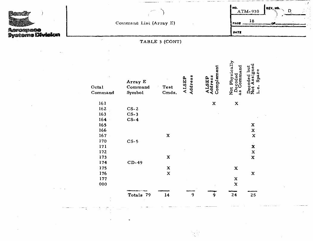
TABLE 3 (CONT)
Array E Command Symbol
CS-2 CS-3 CS-4
CS-5
CD-49
Test Cmds.
X
X
X X
-Totals 79 14
rn tlc rn r:il CD tl) ,...
H :g < <
9
1:i CD e
" rn CD .,..rn_ r:iiCDCl. ell ,... e H 00 o <~u
X
__,... 9
l NO.ATM-930.J ··~~,~~" D, ' ___ ....... __ 18
PA$1! .•• - """"'---OP __ .,. -
DATI
~ ....... "0 ~ ~
.... Cll rn~e >.CD
.Q 'tl e fl. 0 0 u +> CDU
~ 0 rn I'll
X
X
X X
24
'tl +>CD ::S ~ CD .obOJ.t
'tJ•;;; \1 CD rn ell
'&< . U..,_. CD CD 0 • oz ....
X X X
X X X
X
25
,I
ATM-930 D Command List (Array E)
ftAGI 19 Of
DATI
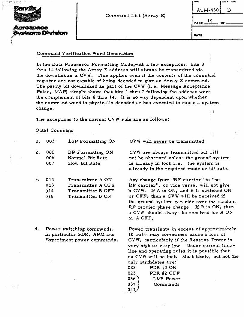
Command Verification Word Generation
In the Data Processor Formatting Mode,with a few exceptions, bits 8 thru 14 following the Array E address will always be transmitted via i
the downlink as a CVW. This applies even if the contents of the comma!nd register are not capable of being decoded to give an Array E command. The parity bit downlinked as part of the CVW (i.e. Message Acceptance Pulse, MAP) simply shows that bits 1 thru 7 following the address were the complement of bits 8 thru 14. It is no way dependent upon whether !
the command word is physically decoded or has executed to cause a system change.
The exceptions to the normal CVW rule are as follows:
Octal Command
1. 003
2. 005 006 007
3. 012 013 014 015
LSP Formatting ON
DP Formatting ON Normal Bit Rate Slow Bit Rate
Transmitter A ON Transmitter A OFF Transmitter B OFF Transmitter B ON
4. Power switching commands, in particular PDR, APM and Experiment power commands.
CVW will never be transmitted.
CVW are always transmitted but will not be observed unless the ground system is already in lock i.e., the system is already in the required mode or bit rate.
Any change from "RF carrier" to "no RF carrier", or vice versa, will not give a CVW. If A is ON, and B is switched ON or OFF, then a CVW will be received if the ground system can ride over the random RF carrier phase change. If B is ON, then a CVW should always be received for A ON or A OFF.
Power transients in excess of approximately 10 watts may sometimes cause a loss of CVW, particularly if the Reserve Power is very high or very low. Under normal tim~line and operating rules it is possible that no CVW will be lost. Most likely, but not the only candidates are: 022 PDR #2 ON 023 PDR #2 OFF
036) LMS Power 037 Commands 041
4.
5. 034 035
6. 122
7. 060 062
DDP X Select DDP Y Select
Switch Uplink
PC fH Select PC /12 Select
ATM-930 D Command List (Array E)
PAGI 20 Of 20
DATI
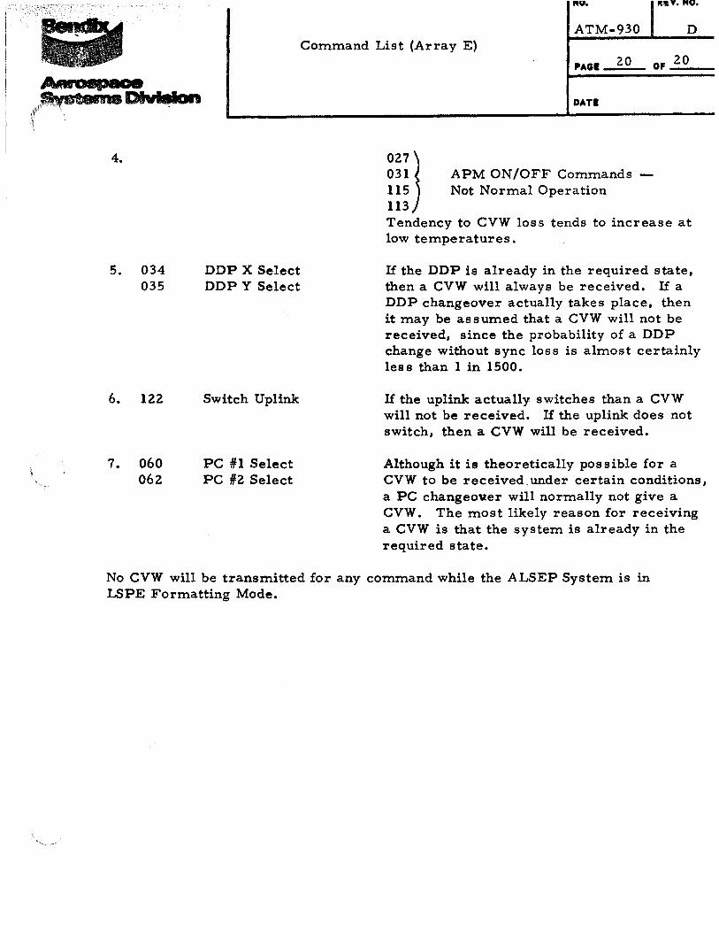
~;iJ APM ON/OFF Commands 115 Not Normal Operation 113 Tendency to CVW loss tends to increase at low temperatures.
If the DDP is already in the required state, then a CVW will always be received. If a DDP changeover actually takes place, then it may be assumed that a CVW will not be received, since the probability of a DDP change without sync loss is almost certainly less than 1 in 1500.
If the uplink actually switches than a CVW will not be received. If the uplink does not switch, then a CVW will be received.
Although it is theoretically possible for a CVW to be received. under certain conditions, a PC changeo~er will normally not give a CVW. The most likely reason for receiving a CVW is that the system is already in the required state.
No CVW will be transmitted for any command while the ALSEP System is in LSPE Formatting Mode.