comment#185-7: clause 86 mdi optical pin layout and connector
TRANSCRIPT

Clause 86 MDI Optical Pin Layout and Connector
Paul Kolesar, CommScopeSharon Lutz, USConec
IEEE P802.3baJanuary 2009

2
Outline
• MPO connector standards• MDI Pin Layout• Cabling Polarity Compatibility• Rationale for Choosing an MDI Connector• Proposed Content for Clause 86.5.1• Proposed Content for Clause 86.5.2• Proposed Content for Clause 86.10.2.3

3
MPO Intermateability Standardization• IEC 61754-7
– Within 61754-7, both 12- and 24-fiber variants of the MPO are standardized.
– Fiber hole and required interface dimensions are defined
– Guide pin & guide pin hole dimensions standardized for SM & MM
• TIA 604-5-D (FOCIS 5)– Harmonized with IEC intermateability
requirements for 12- and 24-fiber MPOs.– Defines up to 72-fiber in standard MPO footprint

4
MPO Outer Housing Dimensions
12.6 mm
7.7 mm

5
IEC fiber hole location standardization
X Y0.125
0.125
0.375 0.375
0.625 0.625
0.875 0.875
1.125 1.125
1.375 1.375
12 Fiber 24 Fiber
XY
0.125
0.125
0.375 0.375
0.625 0.625
0.875 0.875
1.125 1.125
1.375 1.375
0.2500.250

6
MPO Position Definition per TIA 604-5-D

7
MT Optical Interface Standardization
• IEC PAS 61755-3-31 & IEC 61755-3-32– Axial alignment, angular alignment, endface
geometry dimensional requirements for SM physical contact MT to MT connections.
• MM Optical Interface documents initiated in IEC SC86B, WG6

8
MPO Structured Cabling Standardization
• ISO/IEC 24764 (Data Centre Cabling)– Defines MPO as normative connector for
interfaces with > 2 fibers• TIA-568-C.0 & 568-C.3 / TIA-568-B.1-7
– Define Array Cabling Polarity methods and components for duplex and parallel links in structured cabling
– MPO is exemplary array connector

9
MDI Pin Layout
• Definition required to ensure interoperability– Parallel optics introduce more degrees of freedom
that must be constrained for interoperable connectivity • Optimal pin layout will be compatible
with structured cabling– The same array polarity in cabling systems
should support all array applications • without modification of permanent link cabling• with common patch cords
– Implies common connector
• Begin by examining existing array applications

10
Existing 4-Lane VariantsAll looking into the MDI receptacle with the keyway on top
Tx Rx1 2 3 4 4 3 2 1QSFP MSA
POP4 MSAInfiniBand 4xOIF VSR4-03
10GFC
Tx Rx0 1 2 3 3 2 1 0
All specify4 transmitters on left side4 receivers on right side4 unused positions in center
All specify the MPO connectorMale (pinned) in MDI receptacleFemale (unpinned) on patch cord
All require the same array cabling polarity that transposes signals laterally about a vertical center line
Differ in designation nomenclatureNumbering starts from 0 or 1
11
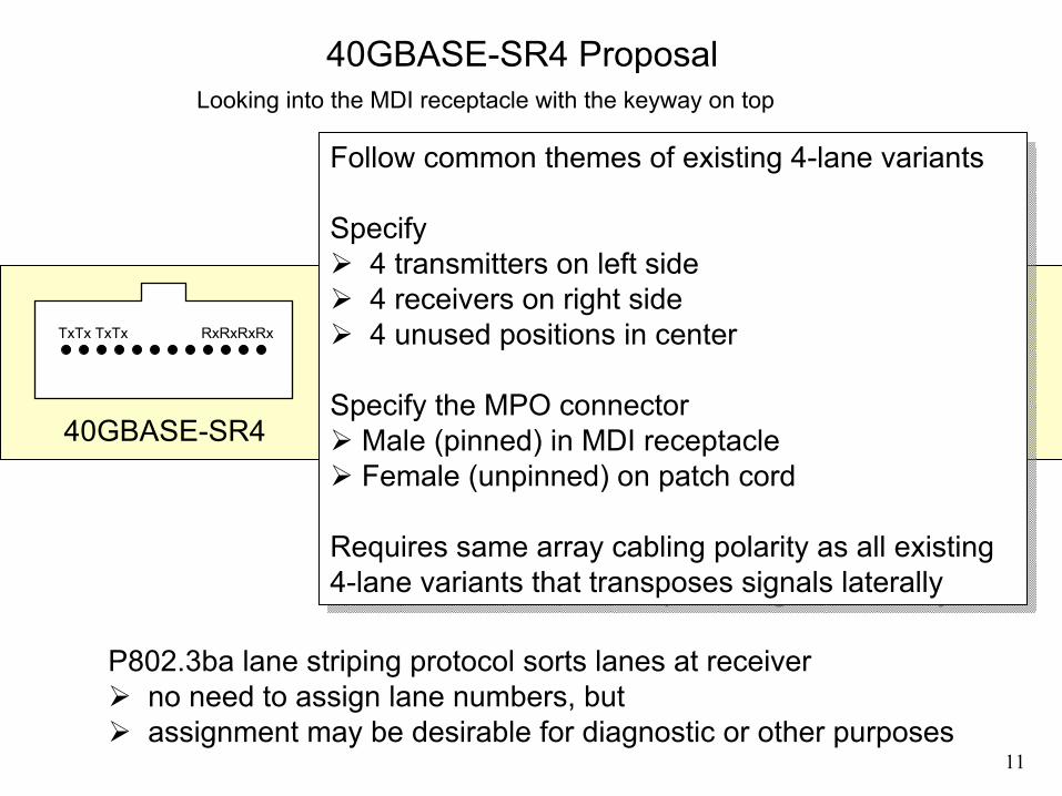
40GBASE-SR4 ProposalLooking into the MDI receptacle with the keyway on top
40GBASE-SR4
TxTx TxTx RxRxRxRx
Follow common themes of existing 4-lane variants
Specify4 transmitters on left side4 receivers on right side4 unused positions in center
Specify the MPO connectorMale (pinned) in MDI receptacleFemale (unpinned) on patch cord
Requires same array cabling polarity as all existing 4-lane variants that transposes signals laterally
P802.3ba lane striping protocol sorts lanes at receiverno need to assign lane numbers, but assignment may be desirable for diagnostic or other purposes
12
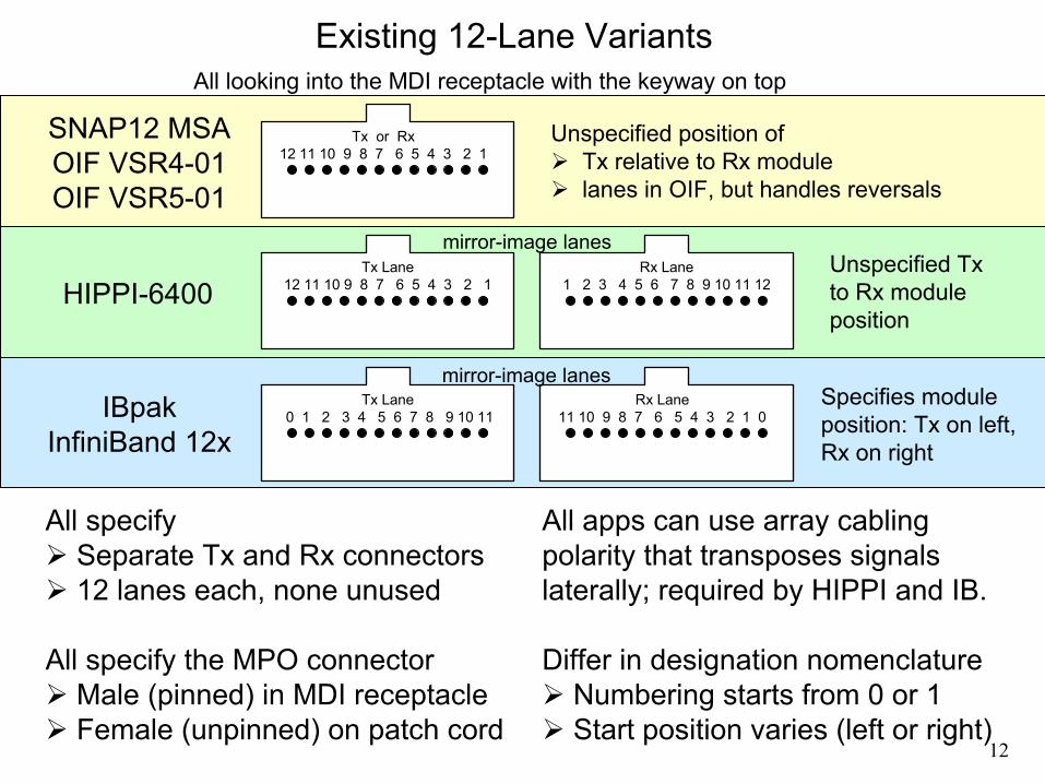
Existing 12-Lane VariantsAll looking into the MDI receptacle with the keyway on top
All specify Separate Tx and Rx connectors 12 lanes each, none unused
All specify the MPO connectorMale (pinned) in MDI receptacleFemale (unpinned) on patch cord
Tx or Rx 12 11 10 9 8 7 6 5 4 3 2 1
SNAP12 MSAOIF VSR4-01OIF VSR5-01
Unspecified position ofTx relative to Rx modulelanes in OIF, but handles reversals
All apps can use array cabling polarity that transposes signals laterally; required by HIPPI and IB.
Differ in designation nomenclatureNumbering starts from 0 or 1 Start position varies (left or right)
Tx Lane12 11 10 9 8 7 6 5 4 3 2 1 HIPPI-6400
Rx Lane1 2 3 4 5 6 7 8 9 10 11 12
Unspecified Txto Rx module position
mirror-image lanes
IBpakInfiniBand 12x
Tx Lane0 1 2 3 4 5 6 7 8 9 10 11
Rx Lane11 10 9 8 7 6 5 4 3 2 1 0
Specifies module position: Tx on left, Rx on right
mirror-image lanes

13
VerticallyStacked
Ports
ReceiverRxRxRxRxRxRxRxRxRxRx
TransmitterTxTx TxTxTx TxTxTx TxTx
SinglePort
RxRxRxRxRxRxRxRxRxRx
TxTx TxTxTx TxTxTx TxTx
100GBASE-SR10 ProposalThree variants, all looking into the MDI receptacle with the keyway on top
All variants can use the same 12-fiber array cabling polarity, required by HIPPI and IB, that transposes signals laterally,
because lane striping sorts lanes. See examples in later slide.
Side-by-Side Ports
TransmitterTxTx TxTxTx TxTxTx TxTx
ReceiverRxRxRxRxRxRxRxRxRxRx
Specify relative position of Rx and Tx
12-position rows with outer positions unused to mitigate alignment challenges
Specify the MPO connectorPinned (male) in MDI receptacleUnpinned (female) on patch cord
Specify relative position of Rx and Tx
12-position rows with outer positions unused to mitigate alignment challenges
Specify the MPO connectorPinned (male) in MDI receptacleUnpinned (female) on patch cord
Side-by-Side Ports follow IB Vertical and Single analogous

14
100GBASE-SR10 ProposalWhy 3 different configurations?
SinglePort
RxRxRxRxRxRxRxRxRxRx
TxTx TxTxTx TxTxTx TxTx
Most compact CXP MSA compatible
Side-by-Side Ports
TransmitterTxTx TxTxTx TxTxTx TxTx
ReceiverRxRxRxRxRxRxRxRxRxRx
Incumbent method SNAP12, IBpakCFP compatible
Vertically Stacked
Ports
ReceiverRxRxRxRxRxRxRxRxRxRx
TransmitterTxTx TxTxTx TxTxTx TxTx
Single-width linear pitchCompatible with traditional 12-fiber array patch cordsHigh-density switch ports
These represent all the likely variants that may be used, and therefore
collectively cover interoperability scenarios

15
Tx
Rx
Rx
Tx
RxTxTxRx
RxTx
TxRx
Polarity Examples Using TIA-568 Method B40GBASE-SR4
100GBASE-SR10
Common, Standard, Permanent-Link Cablingfor All Variants
Common Standard
Patch Cordsfor 3 Variants
RxRx
Tx Tx
Side-by-Side
Vertical
Single
Other polarity methods could also support these variants
16
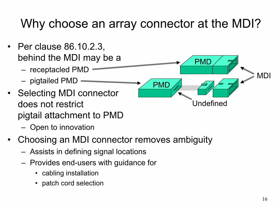
Why choose an array connector at the MDI?
• Per clause 86.10.2.3, behind the MDI may be a– receptacled PMD– pigtailed PMD
• Selecting MDI connector does not restrict pigtail attachment to PMD– Open to innovation
• Choosing an MDI connector removes ambiguity– Assists in defining signal locations– Provides end-users with guidance for
• cabling installation• patch cord selection
MDI
Undefined
PMD
PMD

17
Why choose the MPO as the array connector?
• All known array applications have chosen the MPO– OIF VSR4-03, OIF VSR4-01, OIF VSR5-01, – InfiniBand 4x, InfiniBand 8x, InfiniBand 12x– INCITS 10GFC, INCITS HIPPI-6400
• All known parallel optic MSAs have chosen the MPO– QSFP, POP4, SNAP12, IBpak
• Fully standardized component in TIA and IEC– TIA FOCIS 5, IEC 61754-7
• Chosen by structured cabling standards– Exemplary array connector in TIA-568 (Generic Cabling)– The only array connector in draft ISO 24764 (Data Centre)
• Widely available from many cabling vendors– The array connector of virtually all vendors– MTP® is a brand of MPO

18
Content for Clause 86.5.186.5.1 Optical lane assignments for 40GBASE-SR4The four transmit and four receive optical lanes of 40GBASE-SR4 shall occupy the positions depicted in Figure 86-3 when looking into the MDI receptacle with the connector keyway feature on top. The interface contains eight active lanes within 12 total positions. The transmit optical lanes occupy the leftmost four positions. The receive optical lanes occupy the rightmost four positions. The four center positions are unused. See 86.10.2.3 for MDI optical connector requirements.
Figure 86-3 -- 40GBASE-SR4 optical lane assignments when viewed looking into the MDI receptacle with keyway feature on top.
TxTx TxTx RxRxRxRx

19
Content for Clause 86.5.2 (1 of 4)
86.5.2 Optical lane assignments for 100GBASE-SR10
The ten transmit and ten receive optical lanes of 100GBASE-SR10 shall occupy the positions depicted in Figure 86-4a, or Figure 86-4b, or Figure 86-4c when looking into the MDI optical receptacle(s) with the connector keyway feature(s) on top. The interface contains 20 active lanes within up to 24 total positions arranged in two rows of at least 10 or 12 positions. One row is dedicated to transmit optical lanes and the other row to receive optical lanes. For the depicted 12-position rows, the optical signal lanes occupy the center ten positions of each row with the outermost positions unused. See 86.10.2.3 for MDI optical connector requirements.

20
Content for Clause 86.5.2 (2 of 4)
Figure 86-4a – 100GBASE-SR10 optical lane assignments for side-by-side MDI receptacles when viewed looking into the receptacles with keyway
features on top. Transmitter is on the left and receiver on the right.
TransmitterTxTx TxTxTx TxTxTx TxTx
ReceiverRxRxRxRxRxRxRxRxRxRx

21
Content for Clause 86.5.2 (3 of 4)
Figure 86-4b – 100GBASE-SR10 optical lane assignments for vertically stacked MDI receptacles when viewed looking into the receptacles with
keyway features on top. Receiver is on the top and transmitter on the bottom.
ReceiverRxRxRxRxRxRxRxRxRxRx
TransmitterTxTx TxTxTx TxTxTx TxTx

22
Content for Clause 86.5.2 (4 of 4)
Figure 86-4c – 100GBASE-SR10 optical lane assignments for single MDI receptacle when viewed looking into the receptacle with keyway feature on
top. Transmitter occupies the bottom row and receiver the top row.
RxRxRxRxRxRxRxRxRxRx
TxTx TxTxTx TxTxTx TxTx

23
Content for Clause 86.10.2.3 (1 of 2)86.10.2.3 Medium Dependent Interface (MDI) requirements
The MDI is the interface between the PMD and the “fiber optic cabling” (as shown in Figure 86–7). The 40GBASE–SR4 PMD is coupled to the fiber optic cabling through one connector plug into the MDI optical receptacle. The 100GBASE–SR10 PMD is coupled to the fiber optic cabling through one or two connector plugs into the MDI optical receptacle(s), depending on choice of implementation, as shown in Figures 86-4a, 86-4b, and 86-4c. Example constructions of the MDI include the following:
a) PMD with a connectorized fiber pigtail plugged into an adapter;b) PMD with receptacle.
The MDI adapter or receptacle shall meet the dimensional specifications of IEC 61754-7 interface 7-3, the MPO adapter interface. The plug terminating the optical fiber cabling shall meet the dimensional specifications of IEC 61754-7 interface 7-4, MPO female plug connector flat interface. The MDI shall optically mate with the plug on the optical fiber cabling. See Figure 86-XX. The MDI connection shall meet the interface performance specifications of IEC 61753-1-1 and IEC 61753-022-2.
NOTE—Compliance testing is performed at TP2 and TP3 as defined in 86.4.1, not at the MDI.

24
Content for Clause 86.10.2.3 (2 of 2)
Figure 86-XX – MPO female plug connector flat interface and MDI as a PMD receptacle using MPO adapter interface.