commercial feature testing closed link … feature nowadays ... of the test bench must be aware of...
TRANSCRIPT
METERING INTERNATIONAL ISSUE - 1 | 2011 89
COMMERCIAL FEATURE
Nowadays, electricity meter manufacturers and meter applicants are faced at meter testing with an increasing number of meters with closed links between the current and voltage measuring circuits (I-P links).
The former phantom load testing technique with disconnected voltage and current circuits and common current and voltage sources cannot be applied for interconnected links due to the multiple interconnection points at different potential levels. Elimination of the voltage and current path interaction through interconnection must be achieved via external individual isolation of each meter circuit.
Generally, the isolation method has an additional impact on the measurement accuracy. The test bench is the principal element in the chain. Therefore the accuracy of the test bench is crucial and is subject to mandatory regulations and evaluations. The operator of the test bench must be aware of all the influencing factors and limitations due to the application of components in the measuring chain and must assess their impact on the accuracy. The purpose of this article is to present the impact of isolation circuitry and assessment of the introduced error.
The techniques available for meter isolation are:• Voltage circuit isolation: For single phase meters with only
one current measuring circuit, the isolation can be provided for voltage circuits. The isolation device can be either an individual voltage transformer or a transformer having multiple secondary windings, one for each tested meter.
• Current circuit isolation: For meters with multiple current circuits like single phase meters with two current circuits or three phase meters, the isolation of voltage circuits is not applicable as common interconnection nodes cause unpredictable balance currents flowing between individual current circuits through low impedance voltage circuits. A possible solution for this case is the current isolation transformer.
• Hybrid circuit isolation: Simultaneous voltage and current isolation might be advantageous when an existing voltage circuit isolated test bench has to be extended to the testing of meters with multiple current circuits. The additional current isolation transformer might be an optimum cost solution.
Voltage traNsformersFor voltage circuit isolation either a voltage transformer with several galvanically isolated secondary windings (known as a multi-secondary voltage transformer, MSVT) or individual transformers for each meter position can be used. The individual transformers can be either passive devices with absolute and differential transfer accuracy specification of the group (distributed multi-secondary voltage transformer, D-MSVTTM) or electronically compensated transformers with absolute accuracy specification independent of the load impedance.
An MSVT requires more complicated wiring of the test bench, is designed for one nominal voltage, and in the case of a fault the
TESTING CLOSED LINK METERS MEASUREMENT ACCURACY ASSESSMENT
whole system becomes non-functional. The special wiring of an MSVT can be problematic at upgrade of existing systems.
The advantages of the individual transformer are its simple implementation into an existing test bench, variable nominal voltage operation along with accurate voltage multiplication or division, and the possibility of individual error compensation.
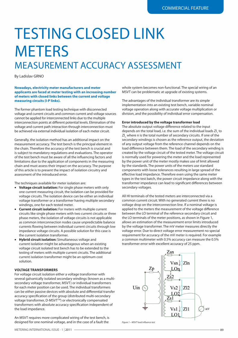
error introduced by the voltage transformer loadThe absolute output voltage difference related to the input depends on the total load, i.e. the sum of the individual loads Zl1 to Zln where n is the total number of secondary circuits. If one of the secondary windings is chosen as the reference output, the deviation of any output voltage from the reference channel depends on the load difference between them. The load of the secondary winding is created by the voltage circuit of the tested meter. The voltage circuit is normally used for powering the meter and the load represented by the power unit of the meter mostly makes use of limit allowed by the standards. The power units of the meters use standard components with loose tolerances resulting in large spread of the effective load impedance. Therefore even using the same meter types in the test batch, the power circuit impedance along with the transformer impedance can lead to significant differences between secondary voltages.
All HI terminals of the tested meters are interconnected via a common current circuit. With no generated current there is no voltage drop on the interconnection line. If a nominal voltage is applied to the meters the measurement of the voltage difference between the LO terminal of the reference secondary circuit and the LO terminals of the meter positions, as shown in Figure 1, allows an estimation of the measurement error limits introduced by the voltage transformer. The mV meter measures directly the voltage error. Due to direct voltage error measurement no special requirement for accuracy of the mV meter is required. For example a common multimeter with 0.5% accuracy can measure the 0.5% transformer error with excellent accuracy of 25 ppm.
By Ladislav GRNO
Figure 1 – MSVT load influence test
METERING INTERNATIONAL ISSUE - 1 | 201190
COMMERCIAL FEATURE
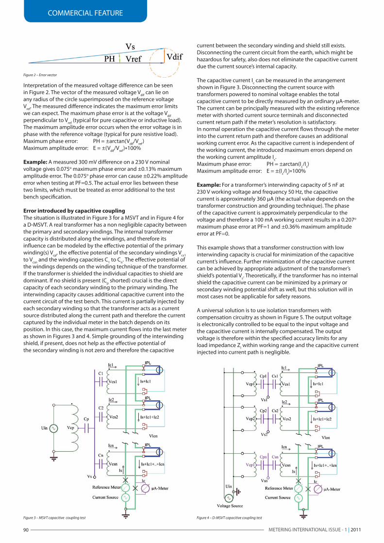
Interpretation of the measured voltage difference can be seen in Figure 2. The vector of the measured voltage Vdif can lie on any radius of the circle superimposed on the reference voltage Vref. The measured difference indicates the maximum error limits we can expect. The maximum phase error is at the voltage Vdif perpendicular to Vref (typical for pure capacitive or inductive load). The maximum amplitude error occurs when the error voltage is in phase with the reference voltage (typical for pure resistive load).Maximum phase error: PH = ±arctan(Vdif/Vref)Maximum amplitude error: E = ±(Vdif/Vref)*100%
example: A measured 300 mV difference on a 230 V nominal voltage gives 0.075o maximum phase error and ±0.13% maximum amplitude error. The 0.075o phase error can cause ±0.22% amplitude error when testing at PF=0.5. The actual error lies between these two limits, which must be treated as error additional to the test bench specification.
error introduced by capacitive couplingThe situation is illustrated in Figure 3 for a MSVT and in Figure 4 for a D-MSVT. A real transformer has a non negligible capacity between the primary and secondary windings. The internal transformer capacity is distributed along the windings, and therefore its influence can be modeled by the effective potential of the primary winding(s) Vcp, the effective potential of the secondary windings Vcs1 to Vcsn and the winding capacities C1 to Cn. The effective potential of the windings depends on the winding technique of the transformer. If the transformer is shielded the individual capacities to shield are dominant. If no shield is present (Cp shorted) crucial is the direct capacity of each secondary winding to the primary winding. The interwinding capacity causes additional capacitive current into the current circuit of the test bench. This current is partially injected by each secondary winding so that the transformer acts as a current source distributed along the current path and therefore the current captured by the individual meter in the batch depends on its position. In this case, the maximum current flows into the last meter as shown in Figures 3 and 4. Simple grounding of the interwinding shield, if present, does not help as the effective potential of the secondary winding is not zero and therefore the capacitive
current between the secondary winding and shield still exists. Disconnecting the current circuit from the earth, which might be hazardous for safety, also does not eliminate the capacitive current due the current source’s internal capacity.
The capacitive current Ic can be measured in the arrangement shown in Figure 3. Disconnecting the current source with transformers powered to nominal voltage enables the total capacitive current to be directly measured by an ordinary µA-meter. The current can be principally measured with the existing reference meter with shorted current source terminals and disconnected current return path if the meter’s resolution is satisfactory.In normal operation the capacitive current flows through the meter into the current return path and therefore causes an additional working current error. As the capacitive current is independent of the working current, the introduced maximum errors depend on the working current amplitude Is.Maximum phase error: PH = ±arctan(Ic/Is)Maximum amplitude error: E = ±(Ic/Is)*100%
example: For a transformer’s interwinding capacity of 5 nF at 230 V working voltage and frequency 50 Hz, the capacitive current is approximately 360 µA (the actual value depends on the transformer construction and grounding technique). The phase of the capacitive current is approximately perpendicular to the voltage and therefore a 100 mA working current results in a 0.207o maximum phase error at PF=1 and ±0.36% maximum amplitude error at PF=0.
This example shows that a transformer construction with low interwinding capacity is crucial for minimization of the capacitive current’s influence. Further minimization of the capacitive current can be achieved by appropriate adjustment of the transformer’s shield’s potential Vs. Theoretically, if the transformer has no internal shield the capacitive current can be minimized by a primary or secondary winding potential shift as well, but this solution will in most cases not be applicable for safety reasons.
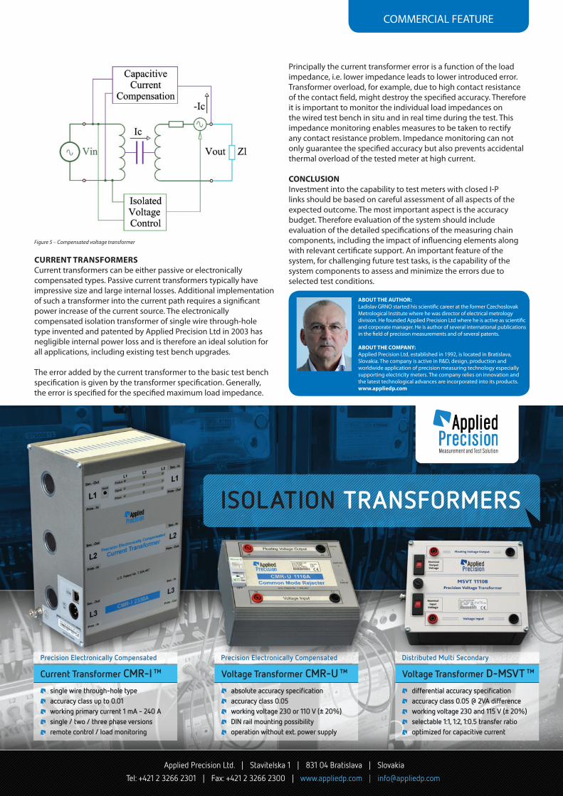
A universal solution is to use isolation transformers with compensation circuitry as shown in Figure 5. The output voltage is electronically controlled to be equal to the input voltage and the capacitive current is internally compensated. The output voltage is therefore within the specified accuracy limits for any load impedance Zl within working range and the capacitive current injected into current path is negligible.
Figure 3 – MSVT capacitive coupling test Figure 4 – D-MSVT capacitive coupling test
Figure 2 – Error vector
COMMERCIAL FEATURE
CurreNt traNsformersCurrent transformers can be either passive or electronically compensated types. Passive current transformers typically have impressive size and large internal losses. Additional implementation of such a transformer into the current path requires a significant power increase of the current source. The electronically compensated isolation transformer of single wire through-hole type invented and patented by Applied Precision Ltd in 2003 has negligible internal power loss and is therefore an ideal solution for all applications, including existing test bench upgrades.
The error added by the current transformer to the basic test bench specification is given by the transformer specification. Generally, the error is specified for the specified maximum load impedance.
aBout tHe autHor:Ladislav GRNO started his scientific career at the former Czechoslovak Metrological Institute where he was director of electrical metrology division. He founded Applied Precision Ltd where he is active as scientific and corporate manager. He is author of several international publications in the field of precision measurements and of several patents.
aBout tHe ComPaNY:Applied Precision Ltd, established in 1992, is located in Bratislava, Slovakia. The company is active in R&D, design, production and worldwide application of precision measuring technology especially supporting electricity meters. The company relies on innovation and the latest technological advances are incorporated into its products.www.appliedp.com
Figure 5 – Compensated voltage transformer
Principally the current transformer error is a function of the load impedance, i.e. lower impedance leads to lower introduced error. Transformer overload, for example, due to high contact resistance of the contact field, might destroy the specified accuracy. Therefore it is important to monitor the individual load impedances on the wired test bench in situ and in real time during the test. This impedance monitoring enables measures to be taken to rectify any contact resistance problem. Impedance monitoring can not only guarantee the specified accuracy but also prevents accidental thermal overload of the tested meter at high current.
CoNClusIoNInvestment into the capability to test meters with closed I-P links should be based on careful assessment of all aspects of the expected outcome. The most important aspect is the accuracy budget. Therefore evaluation of the system should include evaluation of the detailed specifications of the measuring chain components, including the impact of influencing elements along with relevant certificate support. An important feature of the system, for challenging future test tasks, is the capability of the system components to assess and minimize the errors due to selected test conditions.