commercial & industrial wall...
TRANSCRIPT

Commercial & Industrial Wall SystemsDesign Guide
HE324DG - CIWS December 2008

Hebel® CIWS Design Guide 2
1.0 Introduction 3
2.0 Hebel® Commercial & Industrial Wall Systems (CIWS) 3
3.0 Typical Applications 4
4.0 System Design 5
5.0 Design and Detailing Consideration 6
6.0 Structural Performance 8
7.0 Thermal Performance 10
8.0 Fire Performance 11
9.0 Acoustic Performance 12
10.0 Coatings 13
11.0 System Components 14
Appendix A - Hebel® Wall Panel Material Properties 16
Appendix B - Architectural Specification 17
Contents
The system and performance specifications detailed in this guide are guaranteed only for laboratory tested conditions. Actual site conditions should be checked, and advice obtained from an appropriate consultant. Any variations or substitution of materials or assembly requirements, or any compromise in assembly or in quality of the system components may result in failure under critical conditions.
It is the responsibility of the architectural designer and engineering parties to ensure that the details in the Hebel® CIWS Design Guide is appropriate for the intended application. The recommendations of this guide are formulated along the lines of good building practice, but are not intended to be an exhaustive statement of all relevant data. Hebel® accepts no responsibility for or in connection with the quality of the recommendations or their suitability for any purpose when installed.
Hebel® is continuously developing its products. This on-going development may result in changes to product specifications, range and the performance characteristics from time to time. The specifications, range and performance characteristics on which the Hebel® CIWS Design Guide is based, are those current in December 2008.

Hebel® CIWS Design Guide3
1.0 IntroductionCSR Panel Systems is a division of CSR Building Products Limited, one of Australia’s leading building products companies.
CSR Panel Systems manufactures Hebel® Autoclaved Aerated Concrete (AAC). The AAC in Hebel® products is manufactured from sand, lime and cement to which a gas-forming agent is added. The liberated gas expands the mixture, forming extremely small, finely dispersed air pockets, resulting in lightweight aerated concrete.
CSR Panel Systems has manufactured Hebel® products that have won wide acceptance as innovative and environmentally preferable building materials. This is due to their lightweight nature, excellent thermal, fire and acoustic properties and design versatility. These inherent properties of Hebel® products help achieve quick and cost efficient construction practices
as well as providing for comfortable operating environments inside the buildings all year round.
2.0 Hebel® Commercial & Industrial Wall Systems (CIWS)CSR Panel Systems has developed systems for commercial and industrial applications that harness the benefits of lightweight construction where thermal, acoustic and fire properties are desired.
The systems can be installed to either steel frame or concrete structure where a strong, durable, yet quick to install, non-loadbearing cladding is required
The key benefits of using Hebel® CIWS include:
Lighter loads on the structure compared to traditional masonry products reduces the size of structural components and craneage requirements.
Speed of installation and reduced structural sizes mean cost savings compared to traditional masonry construction.
Fast installation and assembly speeds with smaller construction crew requirements.
Excellent thermal resistance performance and effective sound transmission barrier between external and internal environments of the building.
Excellent fire rating properties with fire resistance level (FRL) up to -/240/240.
For further information on Installation elements refer to the Commercial and Industrial Walls Installation Guide available from hebelaustralia.com.au
Image. 2.1 East Gardens Shopping Centre, NSW

Hebel® CIWS Design Guide 4
3.0 Typical ApplicationsHebel® CIWS is designed for applications in buildings that have a commercial/industrial type of business activity purpose. These buildings can be; shopping centres, schools, sport or assembly halls, factories or factory units, clubs, plant or generator rooms, sheds, produce storage facilities, etc. The Building Code of Australia (BCA)generally classifies these buildings into class 5, 6d, 7b, 8, 9a and 9b.
Structurally, the CIWS walls are non-loadbearing, external and internal walls made out of Hebel® wall panels. The panels are steel-reinforced and secured to the structural support frame. The structural support frame is typically steel or portal frame, but it can also be concrete framed. The CIWS wall can be finished off with various combinations of external coatings and internal linings to suit project requirements.
There are two types of CIWS walls (See Table 3.1). The first of these is the CIWS-HZ in which the panels are assembled horizontally. The second is the CIWS-VT in which the panels are assembled vertically.
Table 3.1 System Selection Table for Hebel® CIWS
System Characteristics
• Column support spacing is ≤6m.
• Maximum wall height is ≤12m.
• Low cost solution.
• High speed construction.
• Simple construction techniques.
• High thermal insulation.
• Lightweight construction.
• Easy access to control joints for maintenance.
• High fire resistance level (FRL) rating characteristics.
• Accurate construction tolerances.
• Column support spacing is >6m.
• Maximum wall height is ≤ 6m.
• Low cost solution.
• High speed construction.
• Simple construction techniques.
• High thermal insulation.
• Lightweight construction.
• Easy access to control joints for maintenance.
• High fire resistance level (FRL) rating characteristics.
• Accurate construction tolerances.
CIWS Type
CIWS-HZ
CIWS-VT

Hebel® CIWS Design Guide5
4.1 How to Design a Hebel® CIWSSTEP 1. Determine the panel orientation to suit support frame location and overall wall geometry. The maximum panel length is 6m. Hebel® recommends the following:
The horizontal panel orientation requires structural supports (columns) at 6m maximum spacings. The panel length does not limit the overall wall height.
The vertical panel orientation is limited to wall with an overall wall height ≤ 6m. The spacings of the main building structure can be at distances greater than 6m.
STEP 2. Determine the location of secondary structural steelwork to support the panels, such as mullions or eaves beams between the main structural framing, and for openings (windows).
STEP 3. Design Criteria. Identify the Wall Performance Requirements.
Purpose of structure (Class and importance).
Imposed design actions (wind, local pressure regions).
De�ection criteria.
Thermal E�ciency (R-Value).
Fire Resistance Level (FRL).
Acoustic insulation performance (Rw + Ctr values).
STEP 4. Select a panel thickness and connection type to satisfy performance requirements.
STEP 5. Specify connection requirements to building structure ensuring suitable �re protection where required.
STEP 6. Specify adequate coating system to meet project weather tightness and aesthetic requirements.
4.2 Coastal AreasThe Hebel® CIWS can be used in coastal areas with additional precautions to ensure salt does not build up on the surface of the wall. For buildings which are 200m to 1000m from a shoreline or large expanse of salt water, such as, Swan River (west of the Narrows Bridge), Sydney Harbour (east of the Harbour Bridge or Spit Bridge), one of the following is required:
All horizontal and vertical control joints must be appropriately caulked; or
All walls must be su�ciently exposed from above so that rain can perform natural wash-down of the wall; or
Walls which are protected by so�ts above must be washed down twice per year, to remove salt and debris build-up, particularly at the joints.
In all cases, for steel components ensure appropriate corrosion protection is provided and suitable grade fasteners are selected.
For buildings less than 200m from the shoreline as de�ned above, CSR Panel Systems does not recommend that Hebel® CIWS be used without project speci�c consultation with Hebel® Engineering Services.
4.3 Building TolerancesDuring the construction of the building, there are tolerances to control the accuracy of the building dimensions and locations to an acceptable standard. Additionally, control joints are required in the walls to tolerate and accommodate the movement of the structure (see ‘Control joints’, Section 5.1). These tolerances are nominated in the appropriate speci�cation of the project.
Hebel® recommends that tolerances be speci�ed in the project documents to ensure that support elements, such as steel and concrete columns and slab edges, are fabricated within the surface plane. This will minimise on site trimming of panels and other unnecessary work.
4.0 System Design
IMPORTANTEarthquake loading has not been considered in this design guide.

Hebel® CIWS Design Guide 6
5.1 Control JointsControl joints are necessary to accommodate building movements and to relieve any induced stresses due to thermal expansion and contraction, differential movements between differing materials and support structure movements (i.e. lateral sway or vertical deflection).
Control Joint Placement
Vertical control joints should coincide with control joints in the supporting structure and anywhere that significant structural movement is expected, where the wall abuts a vertical structure, such as a column, or adjacent to large openings.
Horizontal control joints should be placed between the top of the wall and slab soffits/angles or roof structures. The horizontal joints should accommodate any expected vertical deflection from the structure.
Control Joint Width
The designer shall determine the joint width so that the sealant configuration can accommodate the calculated movements.
Typically the control joint widths are as follows:
10mm minimum for vertical control joints.
15mm minimum for horizontal control joints.
All control joints must be filled with an appropriate flexible sealant.
5.2 SealantsAll control joints and gaps between the panels and infill or penetration framing must be filled with an appropriate flexible sealant. The sealant should be designed and installed in accordance with the sealant manufacturer’s specifications. The specifications will provide information regarding priming the surface, geometry of sealant (width/depth ratio), sealant surface profile (i.e. concave), substrate preparation, etc. Typically a backing rod is used to control the depth of sealant and that the sealant is bonded on two sides only.
5.3 CondensationCondensation is a complex problem, and can occur under a variety of conditions, not just cold conditions. Literature on this subject is available from CSIRO/BRANZ/ASHRAE and must be consulted when building in areas where condensation is likely to occur.
5.0 Design and Detailing ConsiderationsIMPORTANT
Minimum specification for control joint details must include:
• 6m maximum distance between control joints on straight wall runs.
• At all corners in walls where movement and/or expansion and contraction is possible.
• At all junctions where Hebel® wall panels abut a structure of different material.
Control joint locations and geometry must be confirmed by the building designer.
The building designer must confirm all control joint widths as the magnitudes of expected horizontal and vertical movements (deflections) might vary from project-to-project.
NOTE Where different types of sealant
come in contact, the designer must ensure the sealants are compatible.
Depending on the type of sealant used the surface of Hebel® wall panels might require some preparation and/or priming.

Hebel® CIWS Design Guide7
5.4 Panel LayoutHebel® CIWS is essentially a flexible modular construction system. By adopting a few simple rules, significant savings can be gained in time and cost, as well as reducing waste and panel handling time.
This is achieved by:
Planning the panel layout with special attention given to the location of openings and penetrations.
Adjacent to openings (windows and doors), we recommend a 600mm wide panel be installed. For large openings, it may be necessary to provide additional structural steel to support the loads shed from the opening.
‘Good Practice’ and ‘Poor Practice’ layouts for vertically installed panels with various penetrations are illustrated in Figures 5.1 and 5.2. This mindset should be adopted for horizontally installed panels as well.
5.5 PenetrationsSmall service penetrations through the panel of the Hebel® CIWS wall should allow for differential movement between the panel and the service. All penetrations are a potential source of water ingress and should be sealed with an appropriate flexible sealant.
5.6 Wet Area Wall ConstructionAll wet area walls should be lined and waterproofed in accordance with Australian Standards and to BCA requirements. Gyprock™ Aquachek or Cemintel™ Wallboard are suitable lining materials for wet area applications.
5.7 Non Hebel® ComponentsComponents, which are not manufactured by Hebel®, such as the structural support elements, Gyprock™ plasterboard, sealants, coatings and others must be designed, installed and handled in accordance with their manufacture’s guidelines and recommendations.
5.8 Deflection Limits of SupportsThe Hebel® CIWS walls shall be considered masonry when selecting the deflection limits for the supporting structure. These deflection limits should include building movements such as:
Base support, the concrete foundation or steel beam support.
Top of wall, this should include the lateral deflection of the main structure of the building.
Sway movements. Lateral sway of the main structure of the building, so that excessive stress is not induced.
5.9 Additional Steel SupportsFor large openings or to allow connection of Hebel® wall panels to the main support structure additional structural steelwork will be required. The project engineer shall design this steelwork.
Hebel® wall panels can be installed to a height equivalent to 10 full panel widths before additional bearing plates are required for higher up panels.
Detail 5.1 Good practice panel/penetration layout.
Detail 5.2 Poor practice panel/penetration layout.

Hebel® CIWS Design Guide 8
6.1 OverviewThe span tables presented in 6.1 and 6.2 show the maximum panel lengths and connection types of the standard Hebel® panels for a range of applications. Panel lengths are denoted by colour code and connection types by letter code.
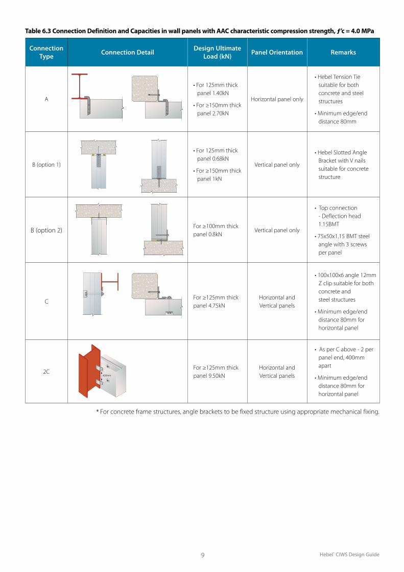
Table 6.3 shows the connection types for securing the Hebel® wall panels to the structural framing and connection capacities.
End Bearing
The wall panels must have a minimum of 50mm end bearing onto the support. Hebel® recommends detailing >50mm minimum end bearing as a construction tolerance to provide for support misalignment. The maximum design bearing stress of the autoclaved aerated concrete (AAC) is 0.5 MPa.
Hebel® panels that form the base of the wall need a minimum bearing length of 300mm between steel/concrete supports.
Cantilevered Panels
Contact Hebel® Engineering Services for advice on cantilevered limitations of the Hebel® wall panels.
Cut Panels
All exposed reinforcement to be painted with a liberal coating of the protection paint – Fentak dipcoat.
Internal Walls
For internal walls, a lateral load of 0.37kPa has been assumed.
Edge Loading
Where vertical loadings are imposed on the edge of Hebel® panels, a structural engineer must be consulted.
6.0 Structural Performance
Table 6.2 Vertical Panels
Pane
l Spa
n (m
)
5.89 B C C C C C C C 2C
5.75 B C C C C C C C 2C
5.5 B C C C C C C C 2C
5.25 B C C C C C C C C
5 B C C C C C C C C
4.75 B C C C C C C C C
4.5 B C C C C C C C C
4.25 B C C C C C C C C
4 B C C C C C C C C
3.75 B C C C C C C C C
3.5 B C C C C C C C C
3.25 B C C C C C C C C
3 B C C C C C C C C
0.375 0.75 1 1.25 1.5 1.75 2 2.5 3
UltimateWind Load (kPa)
Table 6.1 Horizontal Panels
Pane
l Spa
n (m
)
5.89 A A A C C C C C 2C
5.75 A A A C C C C C 2C
5.5 A A A A C C C C 2C
5.25 A A A A A C C C C
5 A A A A A C C C C
4.75 A A A A A C C C C
4.5 A A A A A C C C C
4.25 A A A A A C C C C
4 A A A C A C C C C
3.75 A A A C C C C C C
3.5 A A A A C C C C C
3.25 A A A A C C C C C
3 A A A A A C C C C
0.375 0.75 1 1.25 1.5 1.75 2 2.5 3
Ultimate Wind Load (kPa)
For projects with higher wind loads it may be neccessary to specify custom panels with an increase in reinforcing steel and/or panels in 250mm or 300mm thickness.
Colour Panel Thickness100mm
125mm
150mm
175mm
200mm
225mm
Hebel® CIWS Design Guide9
Table 6.3 Connection Definition and Capacities in wall panels with AAC characteristic compression strength, ƒ’c = 4.0 MPa
Connection Type Connection Detail Design Ultimate
Load (kN) Panel Orientation Remarks
A
• For 125mm thick panel 1.40kN
• For ≥150mm thick panel 2.70kN
Horizontal panel only
• Hebel Tension Tie suitable for both concrete and steel structures
• Minimum edge/end distance 80mm
B (option 1)
• For 125mm thick panel 0.68kN
• For ≥150mm thick panel 1kN
Vertical panel only
• Hebel Slotted Angle Bracket with V nails suitable for concrete structure
B (option 2)For ≥100mm thick panel 0.8kN
Vertical panel only
• Top connection - Deflection head 1.15BMT
• 75x50x1.15 BMT steel angle with 3 screws per panel
CFor ≥125mm thick panel 4.75kN
Horizontal and Vertical panels
• 100x100x6 angle 12mm Z clip suitable for both concrete and steel structures
• Minimum edge/end distance 80mm for horizontal panel
2CFor ≥125mm thick panel 9.50kN
Horizontal and Vertical panels
• As per C above - 2 per panel end, 400mm apart
• Minimum edge/end distance 80mm for horizontal panel
* For concrete frame structures, angle brackets to be fixed structure using appropriate mechanical fixing.
400mm

Hebel® CIWS Design Guide 10
7.1 OverviewBCA 2008 Section J requires minimum thermal performance for external walls on conditioned buildings.
The Performance Requirements for energy efficiency ratings are dependent upon the form of construction (i.e., walls or floors), Class of Building, and the type of areas being separated. The performance requirement is a value that is the Total R-Value, which is the cumulative total of the individual R-Values of the building system components.
The level of insulation provided in a wall is determined by the required Total R-value. The higher the required Total R-value the greater the insulation provided.
7.2 Thermal InsulationIt is recommended that insulation materials be installed to enhance thermal insulation properties and occupant comfort. Insulation also improves the acoustic performance of the wall against outside noise.
The following R-Values for the individual components were assumed in the calculation of the Total R-Value of the wall systems:
Outside air film (4m/s), Rso = 0.04 m2.K/W
Indoor air film (still air) Rsi = 0.12 m2.K/W
Coating system R=0.02 m2 k/w (texture coat and paint)
Hebel® wall panel :
• 100mm thick: 0.63 m2.K/W
• 125mm thick: 0.78 m2.K/W
• 150mm thick: 0.94 m2.K/W
• 175mm thick: 1.10 m2.K/W
• 200mm thick: 1.25 m2.K/W
• 300mm thick: 1.88 m2.K/W
Source: AIRAH Handbook 2007 and 2008, and AS4859
7.0 Thermal Performance
Table 7.1 Thermal PerformanceSystem R-Value (m2K/W)
Wall panel thickness
1. Wall panel only*
2. Wall panel + 25mm cavity
3. Wall panel + 25mm cavity +
sarking
4. Wall panel + 25mm cavity +
75mm PowerPanel™
5. Wall panel + 40mm cavity + R1.0 insulation
6. Wall panel + 90mm cavity + R2.0 insulation
100 0.81 1.03 1.36 1.50 1.87 2.87125 0.96 1.18 1.51 1.65 2.02 3.02150 1.12 1.34 1.67 1.81 2.18 3.18175 1.28 1.50 1.83 1.97 2.34 3.34200 1.43 1.65 1.98 2.12 2.49 3.49300 2.06 2.26 2.61 2.75 3.12 4.12
Meets BCA requirements for building fabric (walls) for Class 5-9b buildings in Climate Zones 1 to 7. Meets BCA requirements for building fabric (walls) for Class 5-9b buildings in Climate Zone 8.
*Wall panel only includes outside air film, coating, Hebel® panel, inside air film. Notes: 1. Cavities are unventilated. 2. Sarking = Bradford EnviroSeal (polymer weave) with e1 = 0.9, e2 = 0.05. 3. R1.0 insulation = Bradford R1.0 Specitel: thickness -
40mm, density-12kg/m3. 4. R2.0 insulation = Bradford R2.0 Gold Wall Batts; thickness - 90mm, density -10kg/m3.

Hebel® CIWS Design Guide11
Table 8.1 External Walls - FRL Detail
Maximum Height 100mm thick panel 100mm thick panel ≥125mm thick panel
Joint Profile Square edge Tongue and Groove Tongue and Groove
3600 -/90/90 -/120/120 -/240/240
4200 -/60/60 -/90/90 -/240/240
4500 -/60/60 -/60/60 -/240/240
6000 - - -/240/240
The Hebel® CIWS can be subjected to a fire loading as the result of either an external fire source, or an internal fire source. When the wall requires a fire resistance level (FRL) rating, Hebel® provides the following guidance.
Hebel® wall panels are primarily designed as non-loadbearing wall elements therefore the structural fire performance of a wall system must be achieved by the building structure.
8.1 External WallsAs shown in the table below all external wall system details (minimum 125mm panel thickness) can achieve a FRL of -/240/240 from an external fire source when constructed in accordance with this design guide.
Where necessary, the designer should ensure the structural support framing and its connections are adequate when subjected to fire conditions. The Building Code of Australia Volume 1 outlines a Functional Statement (CP5) for external walls in fire for a building with two storeys or less:
“Where an external concrete wall could collapse as a complete panel, it must be designed so that in the event of fire within the building, the likelihood of outward collapse is avoided.”
8.2 Internal WallsIf the Hebel® CIWS requires protection from an internal fire source, for example buildings of two storeys or less as
described below, the connection system will require additional fire protection and/or the connection fixed to the support by welding. Where an internal lining is provided, this can be designed as the fire protection system for the connections.
The steel frame manufacturer or project engineer shall approve the connection arrangements for any fire rated lightweight steel support framing.
8.3 Fire Certificates & ReportsCopies of the fire test reports and/or opinions can be obtained by contacting Hebel® Engineering Services.
8.4 Design ConsiderationsFire Stop Penetrations
Penetrations through a Hebel® CIWS to accommodate pipework, electrical cabling or ductwork will have to be protected (fire stop), to prevent the spread of fire through the penetration. The penetration can be protected with proprietary products, such as:
fire rated sealants;
fire collars and intumescent wraps;
fire rated mortars;
fire rated pillows;
fire rated switch boxes.
Hebel® recommends contacting the manufacturer to obtain the appropriate product/solution and installation method for the application and wall configuration.
NOTEThe FRL rating of the wall can be affected by the penetrations and the method adopted to protect these penetrations. A fire collar with a –/120/120 FRL rating will govern the FRL of the wall, even if the wall configuration has a FRL rating of –/240/240.
8.0 Fire Performance
Hebel® CIWS Design Guide 12
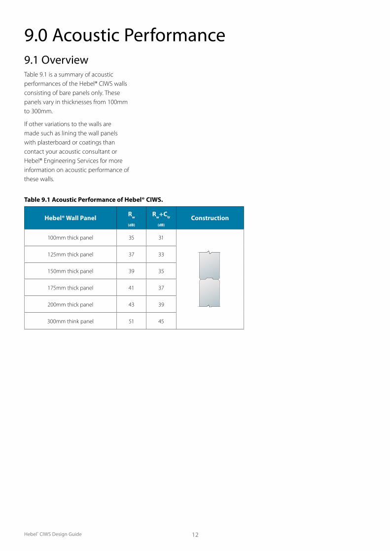
9.0 Acoustic Performance9.1 OverviewTable 9.1 is a summary of acoustic performances of the Hebel® CIWS walls consisting of bare panels only. These panels vary in thicknesses from 100mm to 300mm.
If other variations to the walls are made such as lining the wall panels with plasterboard or coatings than contact your acoustic consultant or Hebel® Engineering Services for more information on acoustic performance of these walls.
Table 9.1 Acoustic Performance of Hebel® CIWS.
Hebel® Wall Panel Rw
(dB)
Rw + Ctr
(dB)
Construction
100mm thick panel 35 31
125mm thick panel 37 33
150mm thick panel 39 35
175mm thick panel 41 37
200mm thick panel 43 39
300mm think panel 51 45

Hebel® CIWS Design Guide13
10.0 Coatings10.1 Internal Finishes Typically in commercial applications, the internal surface of the Hebel® CIWS panels is determined according to project specifications and the intended use of the building.
10.2 External FinishesThe Hebel® CIWS is a face-sealed cladding system and requires an appropriate external coating system and sealant detailing to ensure a water resistant and vapour permeable building envelope is achieved. The coating system should be specified in accordance with the Hebel® High Performance Coating Systems brochure.
The following are items to be considered when selecting a coating system:
Manufacturer approved:
• All coating systems applied to Hebel® external wall systems should be approved by the coating manufacturer as being appropriate for coating an AAC substrate.
Surface adhesion:
• The substrate preparation and coating application should be in accordance with the coating manufacturer’s instructions.
• Before applying finishes in coastal areas (refer to definition in system design), all panels must be thoroughly washed with fresh water to remove any salt residue. Refer to coating manufacturer’s instructions for any additional requirements.
Water resistance:
Refer to Hebel® High Performance Coating Systems brochure.
Vapour Permeability:
Refer to Hebel® High Performance Coating Systems brochure.
10.3 DurabilityThe durability of the Hebel® CIWS can be enhanced by periodic inspection and maintenance. Inspections should include examination of the coatings, flashings and seals. Paint finishes must be maintained in accordance with the manufacturer’s recommendations. Any cracked and damaged finish or sealants, which would allow water ingress, must be repaired immediately by recoating or resealing the effected area. Any damaged flashings or panels must be replaced as for new work.
The durability of the system can also be increased by additional treatment of steelwork, and by painting all exposed sealants to the sealant manufacturer’s recommendations.
Minimum Requirements:• The coating must be durable and
not deteriorate with exposure to light (UV) and weather.
• The coating must be able to bridge a 1mm minimum crack width.
• The coating manufacturer can specify the minimum design specification (thickness), so that the coating is serviceable.
NOTEThis list of performance requirements indicates that a specific fit-for-purpose coating system should be adopted, and that a simple paint coating would most likely be an inadequate coating system. Variations to the coating system should be approved by the coating system manufacturer or representative.
10.4 Coating SystemsHebel® Wall Panel
For Commercial and Industrial applications Hebel® has a number
of recommended coating systems including Monolithic and Express (Economical) options.
For detailed specifications please refer to the Hebel® High Performance Coatings Brochure.
NOTE Hebel® does not recommend cement based on-site renders be applied to Hebel® wall panels.
Concrete Edge Beam
Rendering may also be required to fill the misalignment between the in-situ concrete elements, such as slab edges and columns and the finished wall plane. To exploit the accuracy of the installed wall system and minimise the amount of rendering, Hebel® recommends establishing concrete tolerances that result in the unrendered concrete edge beam being located behind the finished wall plane. This will eliminate the need for scabbling of the edge beam and/or building out the wall surface.
10.5 SealantsAll control joints and gaps between the panels and framing around windows must be caulked with an appropriate flexible sealant. Refer to Section 5.2 for more information on sealants.
Silicone base sealants may not be compatible with coating systems, refer to coating manufacturers for approved sealants.
10.6 Wall FlashingsIn general, flashings shall be designed and installed in accordance with SAA – HB39 1997 - Installation Code for Metal Roofing and Wall Cladding. Stop ends shall be incorporated with all flashings.

Hebel® CIWS Design Guide 14
11.4 Hebel® AdhesiveFig. 11.3 Hebel® Adhesive
Hebel® Adhesive (supplied in 20kg bag) is used for gluing the panels together at vertical and horizontal joints.
11.0 System Components 11.1 General System ComponentsA summary of the components or their equivalents that Hebel® recommends for use in the CIWS is shown in Table 11.1
System component
CIWS Type Supplied by CSR Panel
SystemsCIWS-HZ CIWS-VT
Hebel® Wall Panel 3 3 3
Hebel® Adhesive 3 31 3
Hebel® Mortar 32 32 3
Hebel® Patch 32 32 3
Anticorrosion Coating Agent 32 32 3
DPC or Bond Breaker 32 32
Steel Base Angle 32 32
Fasteners/Fixings 3 3 33
Fire/Acoustic Sealants 3 3
CSR Gyprock Plasterboard 31 31
Coating Systems 31 31
Hebel® HighBuild 31 31 3Note: 1 Optional use as specified by project consultants.2 Use as required.3 Some fixings can be supplied by CSR Panel Systems.
11.2 Hebel® Wall Panel
100-300mm panel
thickness
Table 11.2 Standard & Custom manufactured panel sizes.
Panel type
Thickness (mm)
Length (mm)
Width (mm) Wt (kg/m2)
Standard
100 4500 600 71
125 4500 & 5990 600 89
150 4500 & 5990 600 107
Custom
100 Up to 4500 300 to 600 71
125 Up to 5990 300 to 600 89
150 Up to 5990 300 to 600 107
175 Up to 5990 300 to 600 125
200 Up to 5990 300 to 600 143
225* Up to 5990 300 to 600 160
250* Up to 5990 300 to 600 179
300 Up to 5990 300 to 600 214
Custom panel length and width sizes are available upon request. These are usually designed to suit wind loads and panel spans to suit project specifications, thus reducing installation time and off-cut waste. Custom panel lengths and widths can be produced to the nearest 5mm. Custom panels are subject to minimum order quantity.
Fig. 11.1 Hebel® wall panel x-Section.
The core component of Hebel® CIWS walls is the Hebel® wall panel. The panel is manufactured in a range of stock sizes as detailed in the Table 11.2.
Table 11.1 System components summary.
11.3 Hebel® MortarFig. 11.2 Hebel Mortar
Hebel® Mortar (supplied in 20kg bags) is used as thick bed mortar base to provide a level base for panel installation as well as providing acoustic and fire protection at the base of the panels.
* No Tongue & Groove profiles, only available in straight edge

Hebel® CIWS Design Guide15
11.7 Gyprock™ PlasterboardHebel® CIWS walls can be lined with Gyprock™ Plasterboard on the internal side of the wall if constructing office space or other such areas of the building. The type, thickness and densities of plasterboard will be as per project specifications. Additional information on the Gyprock™ Plasterboard is available through Gyprock™.
11.8 External Finishes
11.5 Anti-corrosion Coating AgentSteel reinforcing exposed on cut panels is to be coated with a liberal application of Fentak Dipcoat, anti-corrosion agent.
11.6 Hebel® PatchFig. 11.4 Hebel® Patch.
Minor Chips or damage to panels are to be repaired using Hebel® Patch (supplied in10kg bags).
Other FixingsFixings such as those required for securing cupboards and other furnishings to Hebel® wall panels are to be specified and installed in accordance with the fixing manufacturer’s instructions.
External finishes can be rendered systems or different types of coating systems. The manufacturer of the external finishes must confirm its suitability for application on AAC products. For more information on external finishes refer to the External Finishes section 10.2 of this guide.
Hebel® HighBuild render is the recommended product.
11.9 SealantAll gaps in internal and external junctions and control joints must be filled with appropriate sealants. For further information refer to sections 5.2 and 10.0 of this guide.
11.10 Brackets, Fasteners & FixingsHebel® Panel Brackets & FixingsFor securing Hebel® wall panels to various support structures a number of different brackets and fixings are available. These brackets & fixings are shown in Fig. 11.6 and they are:
1. Hebel® tension tie
2. Hebel® slotted angle bracket
3. Hebel® V-nails
For more information on how those brackets and fixings are used in various conection assemblies, please refer to connection details as shown in this guide.
Fig. 11.5 Hebel® HighBuild™
Fig. 11.6 Hebel® brackets and fixings.
1 2 3

Hebel® CIWS Design Guide 16
Appendix A: Hebel® Wall Panel Material PropertiesA.1 Manufacturing Tolerances
Length +0 to –1.5mm
Width +0 to –1.5mm
Thickness +1.5 to –1.5mm
Diagonals (max.) 1.5mm
Edge straightness deviation (max.) 1.5mm
A.2 Hebel® Wall Panel Physical Properties
For standard and custom Hebel® wall panel dimensions see Section 11.2.
Standard panel profile is tongue and groove (T&G).
Panel is reinforced with a double layer of steel mesh.
Nominal Dry density of AAC = 550kg /m3
Average working density of AAC = 715kg/m3 at 30% moisture content.
Average working density of panel (AAC + reinforcement) = 751kg/m3 at 30% moisture content.
Average service life density of AAC = 605kg/m3 at 10% moisture content.
Ignitability Index 0
Spread of Flame Index 0
Heat Development Index 0
Smoke Development Index 0-1
A.6 Hebel® Wall Panel Acoustic Ratings
150mm thick wall panel only with no plasterboard or other lining Rw = 39dB, Rw+Ctr = 35dB. For detailed information of acoustic properties for other wall panel thicknesses and CIWS variations please refer to Section 9.0 of this design guide.
A.7 Hebel® Wall Panel Thermal Ratings
R-Value of 150mm thick Hebel® wall panel only with no plasterboard or other lining = 0.94 (m2.K/W). For detailed information of thermal properties for other wall panel thicknesses and CIWS variations please refer to Section 7.0 of this design guide.
A.3 Hebel® Wall Panel Strength Properties
Characteristic Compressive Strength of AAC, f ’m = 4.0MPa
Mean Compressive Strength of AAC = 4.5MPa
Characteristic Modulus of Rupture of AAC, f ’ut = 0.60 MPa
A.4 Hebel® Wall Panel Fire Resistance Level (FRL) Rating1) For fire performance ratings of Hebel® wall panel and CIWS walls refer to Section 8.0 of this publication.
A.5 Fire Hazard IndicesHebel® AAC products have the following early fire hazard indices, determined in accordance with AS1530.3:1990:

Hebel® CIWS Design Guide17
Appendix B: Architectural Specification
This specification should be adopted as a guide only, and shall be superseded by the contract specifications of the project.
* Insert or select appropriate specifications.
Scope
The contractor shall furnish all material and equipment required to satisfactorily complete the installation and jointing of the non-load bearing Hebel® CIWS walls where indicated in the contract specification and/or on the layout drawings.
Materials
All AAC material shall be Hebel® wall panels, as manufactured by Hebel®.
All accompanying fixings shall be those supplied by Hebel® or approved by the project engineer.
All internal lining materials if required including fixings and finishing products shall be those manufactured or supplied by Gyprock™ (or products of equivalent or better performance). Plasterboard shall be manufactured to meet the dimensional requirements of AS/NZS2588 `Gypsum Plasterboard’.
CIWS Type
The contractor shall supply and install non-load bearing Hebel® *CIWS-….. wall, in accordance with CSR Hebel Commercial & Industrial Wall Systems Design and Installation Guides, HE324DG and HE312IG.
CIWS Wall Panel Type
The contractor shall install *……..mm thick Hebel® standard wall panel, as shown on the `Layout’ drawings and in accordance with Hebel® Commercial & Industrial Wall Systems Design and Installation Guides, HE324DG and HE312IG.
Internal Lightweight Steel Framing
Internal Lightweight steel framing *is/is not required. The lightweight steel framing should consist of the following:
*……mm offset from the face of Hebel® wall panels.
*……..mm steel stud/furring channel of *……..mm BMT.
Internal Linings
Internal lining *is/is not required. All internal lining material to be installed in accordance with the manufacturer’s literature.
Hebel® wall panel/lightweight steel frame shall be lined with *….. layer/s of *……mm Gyprock™ plasterboard (or products of equivalent or better performance).
All internal lining, jointing and finishing shall be carried out to *………Level of Finish, in accordance with Gyprock™ Steel Frame Wall System Installation Guide, NoGYP544 and other relevant Gyprock™ Technical Literature.
CIWS Walls Acoustic Field Performance Requirements
Installation of the CIWS walls including; wall panel installation, internal lightweight steel framing, external finishes, internal finishes linings and all other components should be carried out to the level specified for a field acoustic performance of:
*Rw of……...dB and/or Rw + Ctr of………dB.
CIWS Walls Fire Performance Requirements
Hebel® CIWS walls *are/are not required to have a Fire Resistance Level (FRL) rating.
The wall shall have a Fire Resistance Level rating of *FRL …../……/….. for an external fire source, and/or *FRL …../……/….. for an internal fire source, in accordance with the requirements of AS1530.4.
External Coatings and Finishes
Prior to application of external coatings, the contractor shall ensure that:
i) The panels are installed within the tolerances of the project specifications.
ii) All panel-to-panel joints are completely filled with Hebel® Adhesive.
iii) Minor chipping of panels is patched with Hebel® Patch, in accordance with Hebel® Panel Patching Procedure, Technical Bulletin No. HTB794.
iv) All sealants are installed as per manufacturer’s specifications.
Hebel® CIWS walls shall be externally coated with *…………………………………………………………………………………………………….. coating system, which shall be installed to the manufacturer’s specifications.
Internal Coatings and Finishes
Internal coatings and finishes shall be applied on the *Hebel® wall panels/linings.
Hebel® CIWS walls shall be internally coated with *…………………………………………………………………………………………………….. coating system, which shall be installed to the manufacturer’s specifications.
Sealing and Caulking
All control, control and abutment joints shall be caulked with *……………………backing rod and *…………………………………….sealant installed in accordance with the sealant manufacturer’s recommendations.

Available from:
Designed for future livingHebel® is a quality building product, and is backed by CSR Building Products Limited. Further details on engineering and building with Hebel® systems are available in the Hebel® Design Guides and Technical Manual. To obtain a copy, or for further sales or technical assistance, please visit our website.
Hebel® Website:hebelaustralia.com.auFor sales enquiries or further information, please telephone us from anywhere in Australia:
1300 369 448
CSR Panel Systems is a business of CSR Building Products Limited ABN 55 008 631 356.CSR™, PowerWall™ and PowerPanel™ are trademarks of CSR Building Products Limited.
CSR PANEL SYSTEMS112 Wisemans Ferry RoadSomersby NSW 2250Fax (02) 9495 7950
Health & SafetyInformation on any known health risks of our products and how to handle them safely is on their packaging and/or the documentation accompanying them. Additional information is listed in the Material Safety Data Sheet (MSDS). To obtain a copy of a MSDS, telephone 1800 807 668 or download from www.hebelaustralia.com.au > Resources > MSDS. Contractors are required by law to perform their own risk assessments before undertaking work. CSR Panel Systems has sample Safe Work Method Statements (SWMS) to assist in this. To obtain a sample SWMS, refer also to the above sources.
Performance & Certi�cationHebel® is a business of CSR™ Building Products Limited A.B.N. 55 008 631 356. It is a manufacturer and supplier of Hebel® Autoclaved Aerated Concrete (AAC) products. Because it is a manufacturer and supplier only, CSR Panel Systems does not employ people quali�ed as Accredited or Principal Certi�ers. CSR Panel Systems is therefore unable to provide Construction Compliance Certi�cates or Statements of Compliance. CSR Panel Systems conducts appropriate testing of its products and systems to determine performance levels. These include structural, �re and acoustic tests. Testing is conducted and certi�ed by appropriate specialists in these �elds. When using Hebel® products and systems in speci�c projects, such specialists should be consulted to ensure compliance with the Building Code of Australia and relevant Australian Standards.
GuaranteeCSR Panel Systems guarantees the products manufactured by itself and the systems described in Hebel® literature for 7 years, subject to the terms and conditions of the Hebel® Guarantee which can be inspected in the Hebel® website at hebelaustralia.com.au. CSR Panel Systems does not however guarantee the components, products or services, such as installation, supplied by others. Hebel® recommends that only products, components and systems recommended by it be used.
DisclaimerThe information presented herein is supplied in good faith and to the best of our knowledge was accurate at the time of preparation. The provision of this information should not be construed as a recommendation to use any of our products in violation of any patent rights or in breach of any statute or regulation. Users are advised to make their own determination as to the suitability of this information in relation to their particular purpose or speci�c circumstances. Since the information contained in this document may be applied under conditions beyond our control, no responsibility can be accepted by CSR Panel Systems‚ or its sta� for any loss or damage caused by any person acting or refraining from action as a result of misuse of this information.
Hebel® is a registered trademark of Xella Group.CSR Hebel is an exclusive licensee of Xella and a division of CSR Building Products Ltd.
HEBEL1735 08/12 (Update to HE324DG)