commercial wastewater treatment plants ecopod-c manual.pdf · taking effluent samples ... drip...
TRANSCRIPT

ECOPOD-C E200 SERIES
COMMERCIAL WASTEWATER TREATMENT PLANTS
Fixed Film WastewaterTreatment System Design ManualK4479 05/09
P.O. BOX 969, DENHAM SPRINGS, LA 70727
(225) 665-6162 – Telephone
(225) 664-9467 – Fax

2
TablE OF COnTEnTS
notice ................................................................................................................................................................................................ 3
Introduction ..................................................................................................................................................................................... 4
Process Description ..................................................................................................................................................................... 4
Specifications
General Specifications .......................................................................................................................................................... 5
Construction ............................................................................................................................................................................. 5
Electrical Controls ...............................................................................................................................................................5–6
Design Criteria ................................................................................................................................................................................ 7
Operation and Maintenance Manual
Major Components of the ECOPOD-C ............................................................................................................................ 8
Primary Chamber Treatment Tank .................................................................................................................................... 8
Flow Equalization Tank ......................................................................................................................................................... 8
Reactor Tank ............................................................................................................................................................................ 9
Blowers and Motors ............................................................................................................................................................... 9
Dosing Tank .............................................................................................................................................................................. 9
Electrical Controls ................................................................................................................................................................... 9
Sludge Removal ....................................................................................................................................................................... 9
Maintenance Equipment/Tools .......................................................................................................................................... 9
Maintenance Schedule ....................................................................................................................................................... 10
Operation and Maintenance Cost
Equipment Replacement Costs ....................................................................................................................................... 11
Equipment Life Cycle ........................................................................................................................................................... 11
Equipment Consumables ................................................................................................................................................... 12
Labor Time Estimates for Operation and Maintenance ........................................................................................... 12
Sample Requirements
Taking Effluent Samples ..................................................................................................................................................... 13
Solid Removal .............................................................................................................................................................................. 14
Seasonal Use Guidelines ......................................................................................................................................................... 14
Installation Instructions............................................................................................................................................................ 15
Troubleshooting Guide .............................................................................................................................................................. 16
Component Replacement Procedure .................................................................................................................................. 17
General Comments ..................................................................................................................................................................... 17
System layout Drawings .................................................................................................................................................... 18–25
Standard Details Drawings ...................................................................................................................................................... 26
nameplate ..................................................................................................................................................................................... 27
3
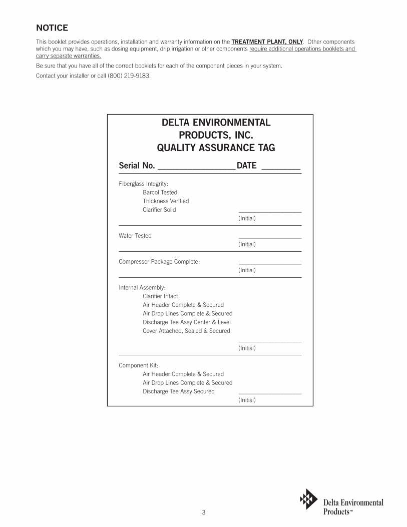
nOTICEThis booklet provides operations, installation and warranty information on the TREaTMEnT PlanT, OnlY. Other components which you may have, such as dosing equipment, drip irrigation or other components require additional operations booklets and carry separate warranties.
Be sure that you have all of the correct booklets for each of the component pieces in your system.
Contact your installer or call (800) 219-9183.
DElTa EnVIROnMEnTalPRODUCTS, InC.
QUalITY aSSURanCE TaG
Serial no. __________________DaTE _________
Fiberglass Integrity: Barcol Tested Thickness Verified Clarifier Solid _____________________ (Initial)
Water Tested _____________________ (Initial)
Compressor Package Complete: _____________________ (Initial)
Internal Assembly: Clarifier Intact Air Header Complete & Secured Air Drop Lines Complete & Secured Discharge Tee Assy Center & Level Cover Attached, Sealed & Secured _____________________ (Initial)
Component Kit: Air Header Complete & Secured Air Drop Lines Complete & Secured Discharge Tee Assy Secured _____________________ (Initial)
4
InTRODUCTIOn
a WORD abOUT YOUR DElTa aDVanCED WaSTEWaTER TREaTMEnT SYSTEM anD HOW IT WORKSThe ECOPOD-C® Fixed Film Wastewater Treatment System that you have purchased produces high quality water suitable for various disposal methods. It is used to enhance your on-site wastewater disposal system. You can be proud that in purchasing your ECOPOD-C® Fixed Film Wastewater Treatment System and with a minimum amount of maintenance, you can directly contribute to a cleaner, safer environment.
All wastewater treatment systems of this type work by using the bacteria that nature has provided. By pumping air into the system, the bacteria grow and thrive in much larger amounts than would occur naturally. The over population of bacteria speeds up the process of breaking down domestic wastewater, making it safe for release into the environment. This entire process takes place within the walls of your specially designed, self-contained ECOPOD-C® Fixed Film Wastewater Treatment System.
The result of this process is a clear, odorless discharge, which meets or exceeds state water quality standards.
By following the few simple steps that you find in this manual, your ECOPOD-C® Fixed Film Wastewater Treatment System will provide you with years of service and the knowledge that you are doing your part to protect public health, our ground water, lakes, rivers, and streams.
The ECOPOD-C® Fixed Film Wastewater Treatment System may be only one of several components required by your health department to provide a complete on-site system.
PROCESS DESCRIPTIOnWastewater enters a pretreatment/settling tank similar to conventional septic tanks. In this tank, debris and settleable solids settle to the bottom and are decomposed by anaerobic bacteria.
The effluent enters the ECOPOD-C® Fixed Film Wastewater Treatment System from the primary tank where it is introduced into an oxygen rich environment. In this oxygen rich environment, a colony of bacteria, called the biomass, develops and is capable of digesting (breaking down) biodegradable waste into carbon dioxide and water. This is a continuous process as long as the biomass is supplied with incoming wastewater and oxygen. The ECOPOD-C® Fixed Film Wastewater Treatment System is a specially designed containment device that houses an engineered plastic media specifically designed to treat domestic wastewater. The ECOPOD-C® Fixed Film Wastewater Treatment System is submerged in a tank of liquid, which operates as a dilution zone. An external air compressor is connected to the tanks to provide the necessary air to the system. There are no moving mechanical parts or filters in the ECOPOD-C® Fixed Film Wastewater Treatment System.
In this system, conditions are favorable only to attached growth bacteria. This means that the most common disadvantages of other types of systems are eliminated. No rising sludge, floating sludge or washouts can occur.
In addition to CBOD and TSS reduction, ammonia nitrogen is one of the contaminants. Wastewater nitrification of the ammonia and de nitrification of nitrates occur within the bacteria masses. A 60%+ removal rate of total nitrogen is common without any type of recirculation or cycling of the blower.
The result of this process is a clear, odorless discharge, which meets or exceeds state water quality standards.
5
SPECIFICaTIOnS
DESIGNED TO ANSI/NSF INTERNATIONAL STANDARD 40, CLASS 1
General SpecificationsThe advanced wastewater treatment system described by these specifications is a Delta Environmental Products, Inc. ECOPOD-C® Fixed Film Wastewater Treatment System Model E______. This device shall essentially consist of a media container, engineered media, air diffusion system, specially designed discharge outlet tee, blower assembly, and control/alarm panel. Additional features and accessories are as shown on the Delta Environmental job drawing or drawings and as hereinafter specified and described.
Operating Conditions
The treatment system shall be capable of treating _______ gallons per day average daily flow (ADF) of domestic raw sewage waste with an organic loading of ______ pounds of BOD5. A minimum of 4,850 cubic feet of aeration capacity shall be provided for each pound of BOD5.
ConstructionFiberglass
The tanks shall be constructed of _ inch minimum thickness fiberglass. The tank shall be molded of fiberglass reinforced polyester resin manufactured by the lay-up and spray technique to assure that the interior has a smooth resin rich finish.
Concrete
The tanks shall be constructed of CONCRETE. The top, bottom, and outer walls of all concrete tanks shall be 3" thick plus or minus l/4" and constructed of concrete with a minimum compressive strength of 3000 psi. The top, bottom and side walls shall also be reinforced uniformly and completely with 10 gauge steel wire on 6" centers both ways (6x6x10x10) or fiber mesh reinforcement at a minimum of 1.2 pounds per yard Harbor light or equal.
Primary Tank
A primary tank shall be provided as shown on the plans to receive the incoming flow. The pretreatment tank shall provide 24 hours hydraulic detention at the ADF rate. The primary tank shall be designed to collect large incoming solids. This shall be accomplished by extending the inlet pipe downward below the trash floatable zone and above the settling zone. The discharge pipe shall also be extended downward so as to draw pretreated sewage from the median zone, keeping both floatable and settle-able solids out of the reactor tank.
Reactor/Dilution Tank
The reactor tank shall be sized to provide a minimum of 33.6 hour hydraulic detention time at the average daily flow (ADF). The dilution zone shall also be designed as to provide optimum liquid-solid separation and shall be sized to provide 24 hours hydraulic detention at the ADF rate.
air Delivery System
Air delivery system shall be constructed of schedule 40 PVC pipe. Air ports shall be designed for non-clogging and shall be maintenance free.
Disinfection (Optional)
A disinfection system of chlorine or Ultraviolet light shall be included in the treatment system to achieve disinfection of the final effluent. Either the chlorinator or the Ultraviolet Light shall be manufactured by the wastewater treatment plant manufacturer.
aeration blower
Provide one aeration blower system with sufficient capacity to furnish the treatment units air requirements. The blower(s) shall be capable of delivering a minimum of 4,850 cubic feet per pound of BOD5 influent at required discharge pressure.
Piping
All necessary piping and valves inside the plant shall be PVC and be provided by the manufacturer. At the exterior wall of the plant, as shown on the plans, the manufacturer shall provide properly sized inlet and outlet connections. The manufacturer shall not be responsible for piping or valves outside the plant. Contractor or owner shall be responsible for necessary piping and valves between all systems.
Workmanship and Experience
All workmanship and materials shall be of the highest quality. The waste treatment plant shall be the product of an experienced manufacturer actively engaged in manufacturing and research and development of sewage treatment systems.
Electrical ControlsCP 13000 Series Duplex / ECOPOD-C PLC Controlled Electrical Panel
General
Furnish an automatic PLC control panel to provide unattended automatic operation of the system. The controller shall be completely assembled; wired and tested .The panel manufacturer shall be certified by Underwriters Laboratories, (U.L.) to manufacture U.L. 508A control panels and shall present their certification documentation with submittal drawings.
Electrical Control Panel
The control panel shall be enclosed in a Nema 4X weather-proof fiberglass enclosure with an inner safety door to isolate all power components and protect the operator. A locking hasp shall be provided on the exterior of the enclosure. Each pump shall be provided with a circuit breaker and a magnetic starter with Class 10 ambient compensated overload relays. HOA selectors and run lights shall be provided for each pump. An alternating relay shall be provided to alternate pumps on successive cycles of operation. Provisions shall be made to provide simultaneous operation of both pumps on high demand. A terminal strip shall be provided to connect all float switches and remote pilot devices. All electrical devices shall be finger safe or have finger safe covers to prevent incidental contact with energized components. Only control panels with high quality individual industrial components with high withstand capability to power surges will be acceptable. Unitized printed circuit board type control panels will not be meet this specification.
(continued on next page)
6
System Features
The Delta Environmental Products 13000 Series professional series control panel utilizes a programmable logic controller (PLC) to automate all functions in a NEMA 4X hinged door enclosure.
The PLC provides:
• Influentpumpcontrol
• MultipleE200Operation
• Adjustableoverridedosingtimes
• Accepts2,3,or4floatarrangements
• SimplexandDuplex
• Multiplepowercircuitscompatibility
• Overridecounter
• Highlevelcounter
• Switchtohandcounter
System Operation
The control panel contains a programmable logic controller (PLC) that periodically turns the influent pumps, located inside the flow equalization tank, on and off. The PLC is capable of time dosing each E200 independently and at different time settings. The control panel is furnished with a Hand-Off-Auto switch located in the panel. The hand mode overrides the PLC timer so the pump can be manually turned on. When the level of water in the flow equalization tank is low, the pump float switch will be in the off position, disabling the pump. The control panel also contains a high level alarm that will sound if a high level is reached in the dose tank which may indicate a system malfunction.
The control panel contains a programmable logic controller (PLC) that manages the pumps and the E200 air blowers. The CP13000 manages either a blower for each E200 or one for all E200s and can be operate a dual blower arrangement. The CP13000 has optional effluent pump circuit that operates simplex or duplex pumps, both on demand and timed dosed. The hand mode overrides the PLC timer so the pump can be manually turned on. When the level of water in the tanks is low, the pump float switch will be in the off position, disabling the pump. The control panel also contains a high level alarm that will sound if a high level is reached in the tanks which may indicate a system malfunction.
Enclosure
The enclosure shall be Nema 4X rated fiberglass and shall be equipped with an inner safety door.
The outer door shall be gasketed. All pilot devices shall be mounted on the inner door. All power and control devices shall be mounted behind the inner safety door on a painted white steel or aluminum sub-panel.
Transformer
A control power transformer (CPT) with fused primary and secondary shall be provided to reduce the control voltage to a maximum of 120 VAC and shall be sized to meet all control requirements. Provide a transformer when the voltage is 3/208 VAC , 3/240 VAC, 3 wire and 3/480 VAC. Transformer may be deleted where a neutral is supplied to provide 120 VAC line to neutral voltage.
Single Phase Motor Starting Modules
Furnish when required by the pump manufacturer, all necessary start relay(s), start capacitor(s) and run capacitors(s) needed for the correct operation of single phase motors. All start/run components and circuits shall be compatible with the pump motor(s) being used. (Applies to single-phase control panels only.)
Circuit breakers
The power system shall contain two back panel mounted branch thermal magnetic motor circuit breakers. The protector operating mechanism shall be quick make, quick break and trip free.
Motor Starters
The motor starters shall be full voltage, non-reversing, horsepower rated with Class 10 ambient compensated overload relays and sized for the specified pumps. The overload relays shall contain an additional N.O. (normally open) contact to provide a crossover circuit enabling the opposite pump to run on an overload trip.
Moisture Detection
Where submersible pumps that have moisture detectors utilized, a moisture detection circuit shall be provided to sense moisture in the pump seals. A warning light inside the panel shall illuminate upon this condition, but shall not cause the pump to lockout. However where the moisture detector is internally connected in series with the over temperature detector, it shall stop the pump.
Over Temperature Protection
The panel shall be wired to connect an over temperature device in or on the pump that will activate on high temperature and stop the pump. The temperature device shall automatically reset when the temperature drops to normal.
Options [Engineer to make selections if any. list is from most common to least common]
The following options shall also be provided:
• Maindisconnectswitchaccessiblefrominsidepanel.
• Lightningarrestertolimitpowersurges.
• Elapsedtimemeterstorecordpumpruntimes.
• Phasemonitortoprotectmotorsfromphasefailure(3phasepanels only)
• DuplexGFCIonoutsideofenclosure(120/240singlephasepanels only)
• Remotealarmlightinsteadofpanelmounted.
• Stainlesssteelenclosureinsteadoffiberglass.
• Greenrunlightsinsteadofred.
• NEMAratedstarters
• Hightemperaturelockoutwithmanualresetpushbuttonfornon-submersible pumps.
• Mountingpole,junctionbox,andsealbelowpaneltopreventgases from entering panel.
• Intrinsicallysaferelays.
• RemoteMonitor
7
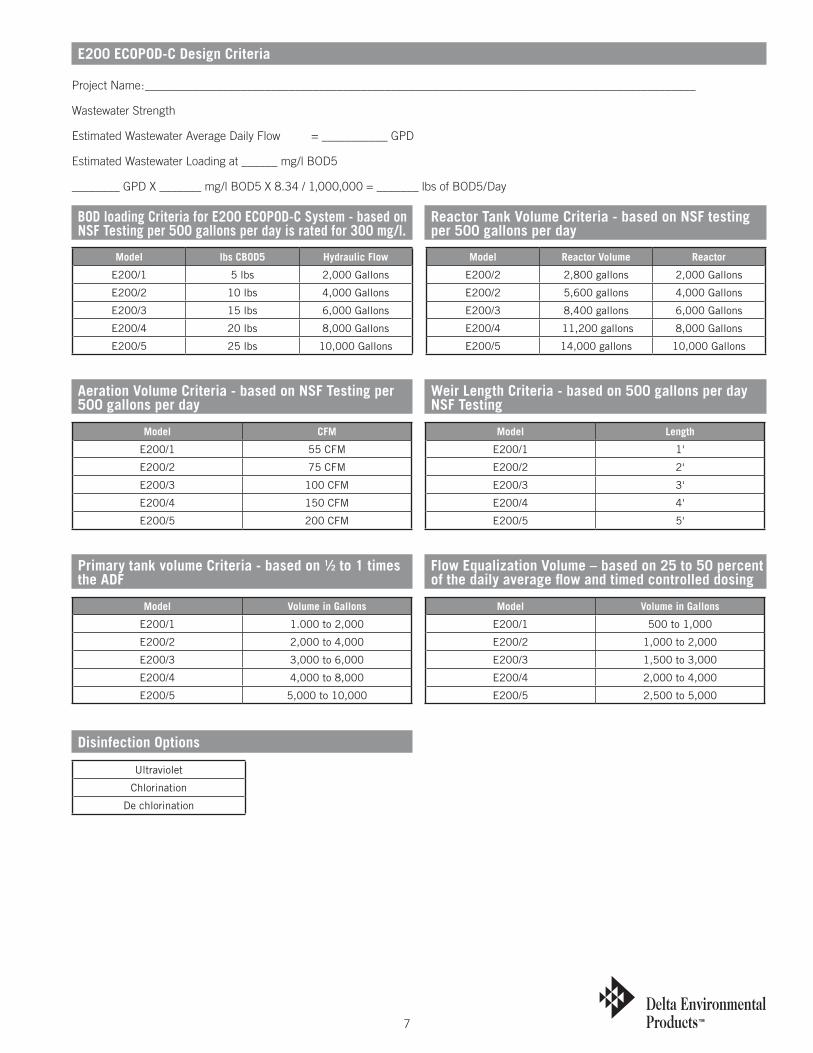
BOD loading Criteria for E200 ECOPOD-C System - based on NSF Testing per 500 gallons per day is rated for 300 mg/l.
Aeration Volume Criteria - based on NSF Testing per 500 gallons per day
Primary tank volume Criteria - based on 1⁄2 to 1 times the ADF
Disinfection Options
Weir Length Criteria - based on 500 gallons per day NSF Testing
Flow Equalization Volume – based on 25 to 50 percent of the daily average flow and timed controlled dosing
Reactor Tank Volume Criteria - based on NSF testing per 500 gallons per day
Model lbs CBOD5 Hydraulic Flow
E200/1 5 lbs 2,000 Gallons
E200/2 10 lbs 4,000 Gallons
E200/3 15 lbs 6,000 Gallons
E200/4 20 lbs 8,000 Gallons
E200/5 25 lbs 10,000 Gallons
Model Reactor Volume Reactor
E200/2 2,800 gallons 2,000 Gallons
E200/2 5,600 gallons 4,000 Gallons
E200/3 8,400 gallons 6,000 Gallons
E200/4 11,200 gallons 8,000 Gallons
E200/5 14,000 gallons 10,000 Gallons
Model CFM
E200/1 55 CFM
E200/2 75 CFM
E200/3 100 CFM
E200/4 150 CFM
E200/5 200 CFM
Model Volume in Gallons
E200/1 1.000 to 2,000
E200/2 2,000 to 4,000
E200/3 3,000 to 6,000
E200/4 4,000 to 8,000
E200/5 5,000 to 10,000
Ultraviolet
Chlorination
De chlorination
Model Length
E200/1 1'
E200/2 2'
E200/3 3'
E200/4 4'
E200/5 5'
Model Volume in Gallons
E200/1 500 to 1,000
E200/2 1,000 to 2,000
E200/3 1,500 to 3,000
E200/4 2,000 to 4,000
E200/5 2,500 to 5,000
E200 ECOPOD-C Design Criteria
Project Name:____________________________________________________________________________________________
Wastewater Strength
Estimated Wastewater Average Daily Flow = ___________ GPD
Estimated Wastewater Loading at ______ mg/l BOD5
________ GPD X _______ mg/l BOD5 X 8.34 / 1,000,000 = _______ lbs of BOD5/Day
8
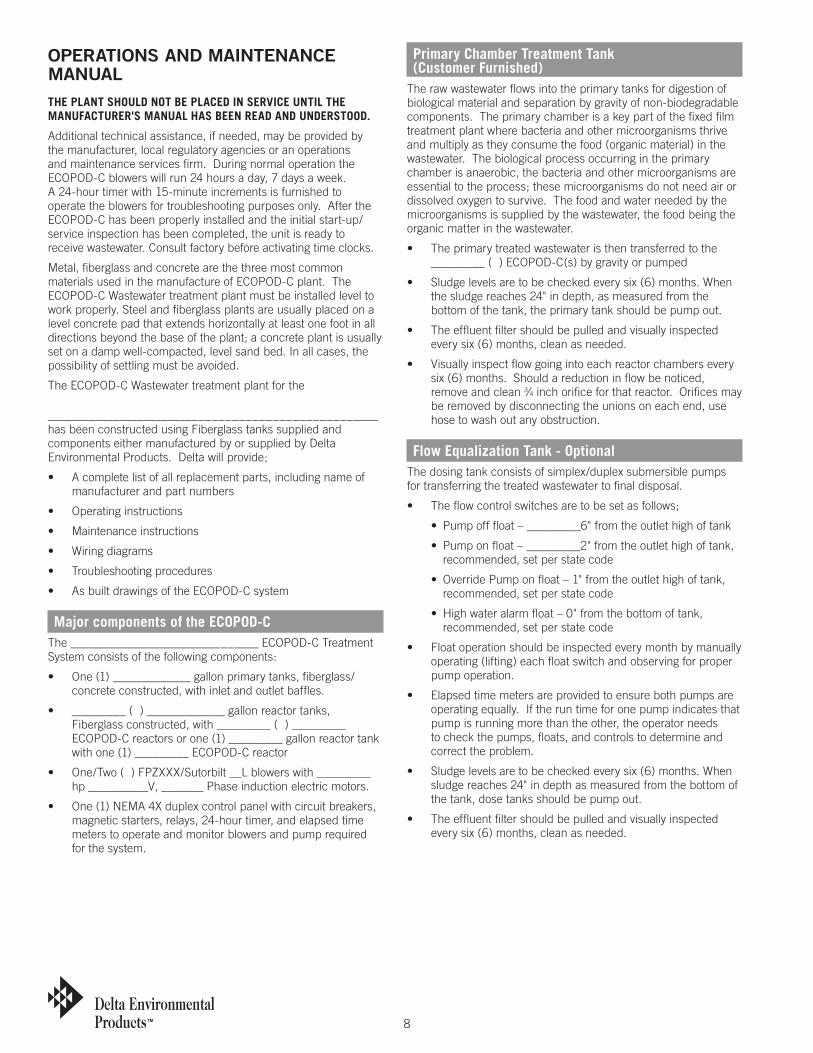
OPERaTIOnS anD MaInTEnanCE ManUalTHE PLANT SHOULD NOT BE PLACED IN SERVICE UNTIL THE MANUFACTURER'S MANUAL HAS BEEN READ AND UNDERSTOOD.
Additional technical assistance, if needed, may be provided by the manufacturer, local regulatory agencies or an operations and maintenance services firm. During normal operation the ECOPOD-C blowers will run 24 hours a day, 7 days a week. A 24-hour timer with 15-minute increments is furnished to operate the blowers for troubleshooting purposes only. After the ECOPOD-C has been properly installed and the initial start-up/service inspection has been completed, the unit is ready to receive wastewater. Consult factory before activating time clocks.
Metal, fiberglass and concrete are the three most common materials used in the manufacture of ECOPOD-C plant. The ECOPOD-C Wastewater treatment plant must be installed level to work properly. Steel and fiberglass plants are usually placed on a level concrete pad that extends horizontally at least one foot in all directions beyond the base of the plant; a concrete plant is usually set on a damp well-compacted, level sand bed. In all cases, the possibility of settling must be avoided.
The ECOPOD-C Wastewater treatment plant for the
____________________________________________________ has been constructed using Fiberglass tanks supplied and components either manufactured by or supplied by Delta Environmental Products. Delta will provide;
• Acompletelistofallreplacementparts,includingnameofmanufacturer and part numbers
• Operatinginstructions
• Maintenanceinstructions
• Wiringdiagrams
• Troubleshootingprocedures
• AsbuiltdrawingsoftheECOPOD-Csystem
Major components of the ECOPOD-CThe _______________________________ ECOPOD-C Treatment System consists of the following components:
• One(1)_____________gallonprimarytanks,fiberglass/ concrete constructed, with inlet and outlet baffles.
• _________()_____________gallonreactortanks,Fiberglass constructed, with _________ ( ) _________ ECOPOD-C reactors or one (1) _________ gallon reactor tank with one (1) _________ ECOPOD-C reactor
• One/Two()FPZXXX/Sutorbilt__Lblowerswith_________hp __________V, _______ Phase induction electric motors.
• One(1)NEMA4Xduplexcontrolpanelwithcircuitbreakers,magnetic starters, relays, 24-hour timer, and elapsed time meters to operate and monitor blowers and pump required for the system.
Primary Chamber Treatment Tank (Customer Furnished)
The raw wastewater flows into the primary tanks for digestion of biological material and separation by gravity of non-biodegradable components. The primary chamber is a key part of the fixed film treatment plant where bacteria and other microorganisms thrive and multiply as they consume the food (organic material) in the wastewater. The biological process occurring in the primary chamber is anaerobic, the bacteria and other microorganisms are essential to the process; these microorganisms do not need air or dissolved oxygen to survive. The food and water needed by the microorganisms is supplied by the wastewater, the food being the organic matter in the wastewater.
• Theprimarytreatedwastewateristhentransferredtothe_________ ( ) ECOPOD-C(s) by gravity or pumped
• Sludgelevelsaretobecheckedeverysix(6)months.Whenthe sludge reaches 24" in depth, as measured from the bottom of the tank, the primary tank should be pump out.
• Theeffluentfiltershouldbepulledandvisuallyinspectedevery six (6) months, clean as needed.
• Visuallyinspectflowgoingintoeachreactorchamberseverysix (6) months. Should a reduction in flow be noticed, remove and clean 3⁄4 inch orifice for that reactor. Orifices may be removed by disconnecting the unions on each end, use hose to wash out any obstruction.
Flow Equalization Tank - OptionalThe dosing tank consists of simplex/duplex submersible pumps for transferring the treated wastewater to final disposal.
• Theflowcontrolswitchesaretobesetasfollows;
• Pumpofffloat–_________6"fromtheoutlethighoftank
• Pumponfloat–_________2"fromtheoutlethighoftank,recommended, set per state code
• OverridePumponfloat–1"fromtheoutlethighoftank,recommended, set per state code
• Highwateralarmfloat–0"fromthebottomoftank,recommended, set per state code
• Floatoperationshouldbeinspectedeverymonthbymanuallyoperating (lifting) each float switch and observing for proper pump operation.
• Elapsedtimemetersareprovidedtoensurebothpumpsareoperating equally. If the run time for one pump indicates that pump is running more than the other, the operator needs to check the pumps, floats, and controls to determine and correct the problem.
• Sludgelevelsaretobecheckedeverysix(6)months.Whensludge reaches 24" in depth as measured from the bottom of the tank, dose tanks should be pump out.
• Theeffluentfiltershouldbepulledandvisuallyinspectedevery six (6) months, clean as needed.

9
Reactor TankAfter raw wastewater flows through the various devices where pretreatment occurs, it is pumped into the reactor tank/chamber and flows by gravity downward through the media and is re-circulated by the air entering below the media. The reactor chamber is the key part of the treatment system; where bacteria and other aerobic microorganisms attach to the media, thrive, multiply and consuming the food (organic material) in the wastewater. This biological process requires air/dissolved oxygen in order for the bacteria and other microorganisms to survive and thrive. The dissolved oxygen is supplied by pumping air through the air distribution system and allowing it to rise through the mead.
The reactor tank/chamber also houses the clarifier where the microorganisms are allowed to settle, there by producing a clear effluent to be discharged to final disposal.
The reactor tank must be visually inspected monthly.
• Observationshouldbemadeforclarityofeffluent,floatablesolids on the surface, and to ensure proper aeration is occurring.
• Olfactorytest(sniff)forodors.
• Sludgelevelsaretobecheckedeverysix(6)months.Whensludge reaches 24" in depth, as measured from the bottom of the tank, reactor tanks should be pump out.
Blowers And MotorsBlower maintenance such as changing oil and grease is important to successful operation.
• Seeattachedblowermanufacturer’soperationandmaintenance manual.
An air filter is attached to the intake of the blower. This filter may be of the disposable type (paper) or permanent (wire mesh), in either case they must be kept clean for maximum blower life and output.
• Seeattachedblowermanufacturer’soperationandmaintenance manual.
A check valve on the blower discharge piping is provided to prevent water from entering the drop pipe when the blower is off. This unit has duplex alternating blowers with a common manifold; a check valve must be located between the blower outlets and the common manifold to prevent the blower that is not in operation from having a vacuum created on it, causing a backward rotation resulting in damage.
• Ifbackwardrotationisnoticed,disassemblythecheckvalve/valves and check for proper operation or replace with a new valve.
• Ifwaterispresent,inoraroundtheblower,disassemblethecheck valve/valves and check for proper operation or replace with a new valve.
An electric motor is used to power the blower with V-belts transferring power from the motor to the blower. Bearings and belts may be damaged by over-tightening the V-belts;
• Greasefittingsprovidedonelectricalmotorsmonthly.
• TheoperatorshouldbeabletodepresstheV-beltapproximately one (1) inch at the midpoint between the blower and motor for a properly tensioned belt, adjust as needed, replace as required.
• Iftwo()V-beltsconnecttheblowerandmotorandonebecomes damaged, both should be replaced.
Dosing Tank – OptionalThe dosing tank consists of simplex/duplex submersible pumps for transferring the treated wastewater to final disposal.
• Theflowcontrolswitchesaretobesetasfollows;
• Pumpofffloat–_________"frombottomoftank
• Pumponfloat–_________"fromthebottomoftank,recommended, set per state code
• LagPumponfloat–_______"fromthebottomoftank,recommended, set per state code
• Highwateralarmfloat–______"fromthebottomoftank,recommended, set per state code
• Floatoperationshouldbeinspectedeverymonthbymanuallyoperating (lifting) each float switch and observing for proper pump operation.
• Elapsedtimemetersareprovidedtoensurebothpumpsareoperating equally. If the run time for one pump indicates that pump is running more than the other, the operator needs to check the pumps, floats, and controls to determine and cor-rect the problem.
• Sludgelevelsaretobecheckedeverysix(6)months.Whensludge reaches 24" in depth as measured from the bottom of the tank, dose tanks should be pump out.
• Theeffluentfiltershouldbepulledandvisuallyinspectedevery six (6) months, clean as needed.
Electrical ControlsElectrical controls panel should visually inspected during every plant inspection for proper operation of blowers and pumps as well as signs of physical damage. The ECOPOD-C blower operates 24 hours a day, 7 days a week. The blowers operate on an alternator, which switches each blower every 12 hours. Elapsed time meters are provided to ensure both blowers are operating equally.
• Checkandrecordelapsedtimeforblowersandpumps.
• Manuallyactivatetheaudibleandvisualalarmfunctions.
Sludge RemovalWhen sludge is remove by pump truck. Sludge removal is performed by placing a pump or hose from the pump truck at the bottom of the tanks until all of the sludge is removed.
Maintenance Equipment/ToolsMost large wastewater treatment plants are operated by trained individuals who use sophisticated equipment and procedures. Smaller plants are usually operated by personnel have limited training and use elementary testing procedures and simple equipment. Nonetheless, smaller plants can be operated successfully. Parameters that can be monitored easily and that give a good picture of the treatment plant's condition are:
• Settleability
• pH
• Color
• Dissolvedoxygen
Required test equipment includes: _________-Sludge Judge, DO test kit; pH test kit; two calibrated quart jars; and elbow-length rubber gloves.
10
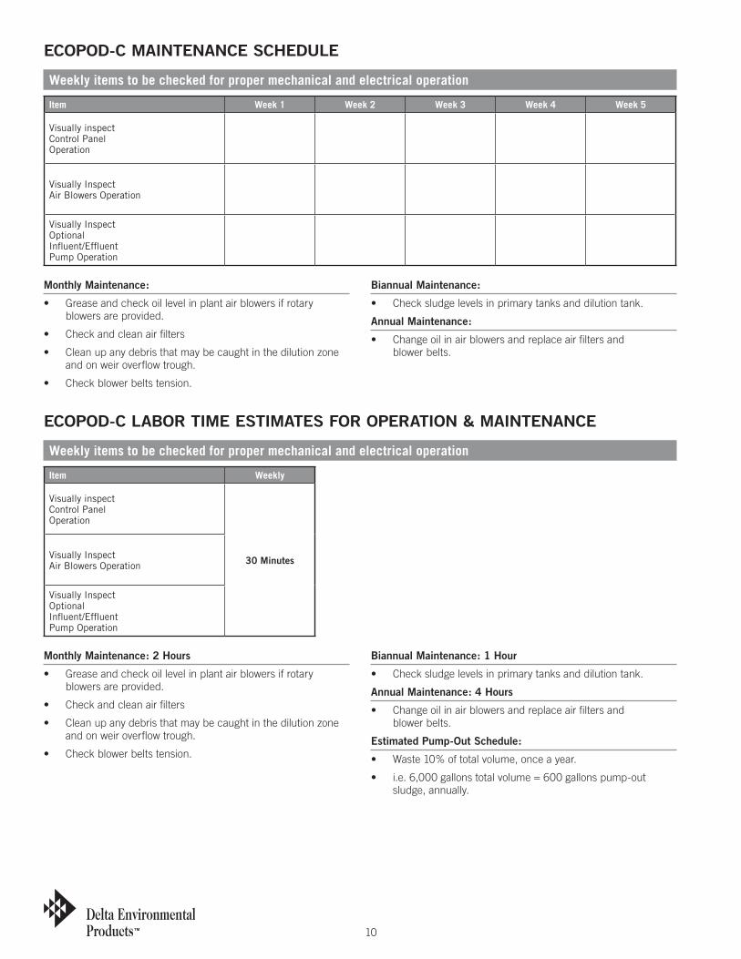
Item Week 1 Week 2 Week 3 Week 4 Week 5
Visually inspectControl PanelOperation
Visually InspectAir Blowers Operation
Visually InspectOptionalInfluent/Effluent Pump Operation
Item Weekly
Visually inspectControl PanelOperation
30 MinutesVisually InspectAir Blowers Operation
Visually InspectOptionalInfluent/Effluent Pump Operation
Weekly items to be checked for proper mechanical and electrical operation
Weekly items to be checked for proper mechanical and electrical operation
ECOPOD-C MaInTEnanCE SCHEDUlE
ECOPOD-C labOR TIME ESTIMaTES FOR OPERaTIOn & MaInTEnanCE
Monthly Maintenance:
• Greaseandcheckoillevelinplantairblowersifrotaryblowers are provided.
• Checkandcleanairfilters
• Cleanupanydebristhatmaybecaughtinthedilutionzoneand on weir overflow trough.
• Checkblowerbeltstension.
biannual Maintenance:
• Checksludgelevelsinprimarytanksanddilutiontank.
annual Maintenance:
• Changeoilinairblowersandreplaceairfiltersand blower belts.
Monthly Maintenance: 2 Hours
• Greaseandcheckoillevelinplantairblowersifrotaryblowers are provided.
• Checkandcleanairfilters
• Cleanupanydebristhatmaybecaughtinthedilutionzoneand on weir overflow trough.
• Checkblowerbeltstension.
biannual Maintenance: 1 Hour
• Checksludgelevelsinprimarytanksanddilutiontank.
annual Maintenance: 4 Hours
• Changeoilinairblowersandreplaceairfiltersand blower belts.
Estimated Pump-Out Schedule:
• Waste10%oftotalvolume,onceayear.
• i.e.6,000gallonstotalvolume=600gallonspump-outsludge, annually.
11
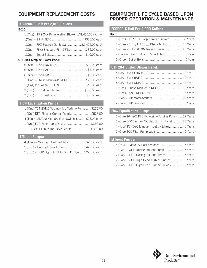
EQUIPMEnT REPlaCEMEnT COSTS
ECOPOD-C Unit Per 2,000 Gallons:E-2.0:
1(One)–FPZXXXRegenerativeBlower ...$1,425.00 each or
1(One) – 1 HP, TEFC ...................................... $325.00 each
1(One)–FPZSutorbilt2LBlower ................$1,425.00 each
1(One) – Filter Stoddard F64-2 Filter ............... $ 85.00 each
1(One) – Set of Belts ........................................ $40.00 each
CTF 284 Simplex blower Panel:
6 (Six) – Fuse-FNQ-R-1/2 ................................ $20.00 each
6 (Six) – Fuse-BAF-2 .......................................... $4.00 each
6 (Six) – Fuse-GMA-2 ........................................ $2.00 each
1 (One) – Phase Monitor-PLMU-11 ....................$70.00 each
1(One)Clock-FM-1STUZL .............................. $40.00 each
2 (Two) 3 HP Motor Starters ............................$150.00 each
2 (Two) 3 HP Overloads ................................... $50.00 each
Flow Equalization Pumps: 1 (One) T64-20115 Submersible Turbine Pump .......$225.00
1 (One) DFC Simplex Control Panel .........................$575.00
4 (Four) P2NO20 Mercury Float Switches......... $25.00 each
1 (One) ECO Filter Pump Vault ................................$350.00
1 (1) ECOFILTER Pump Filter Set Up .......................$360.00
Effluent Pumps: 4 (Four) – Mercury Float Switches .................... $25.00 each
2 (Two) – Dosing Effluent Pumps ................... $425.00 each
2 (Two) – 1⁄2HP High-Head Turbine Pumps ..... $225.00 each
EQUIPMEnT lIFE CYClE baSED UPOn PROPER OPERaTIOn & MaInTEnanCE
ECOPOD-C Unit Per 2,000 Gallons:b-2.0:
1(One)–FPZ1HPRegenerativeBlower ................8 Years
1 (One) – 2 HP, TEFC, __ Phase Motor ...................10 Years
1 (One) – Sutorbilt, 3M Rotary Blower .....................20 Years
2 (Two) – Filter Stoddard F64-2 Filter ......................... 1 Year
1 (One) – Set of Belts ................................................. 1 Year
CTF 284 Duplex Blower Panel: 6 (Six) - Fuse-FNQ-R-1/2 ..........................................2 Years
6 (Six) - Fuse-BAF-2 .................................................2 Years
6 (Six) - Fuse-GMA-2 ................................................2 Years
1 (One) - Phase Monitor-PLMU-11 ..........................10 Years
1(One)Clock-FM-1STUZL .......................................5 Years
2 (Two) 3 HP Motor Starters ....................................20 Years
2 (Two) 3 HP Overloads ..........................................10 Years
Flow Equalization Pumps : 1 (One) T64-20115 Submersible Turbine Pump .......12 Years
1 (One) DFC Simplex /Duplex Control Panel ............20 Years
4 (Four) P2NO20 Mercury Float Switches..................5 Years
1 (One) ECO Filter Pump Vault ..................................5 Years
Effluent Pumps: 4 (Four) – Mercury Float Switches .............................5 Years
2 (Two) – 1⁄2HP Dosing Effluent Pumps ......................5 Years
2 (Two) – 1 HP Dosing Effluent Pumps ......................5 Years
2 (Two) – 1⁄2HP High-Head Turbine Pumps ................5 Years
2 (Two) – 1 HP High-Head Turbine Pumps ................5 Years
12
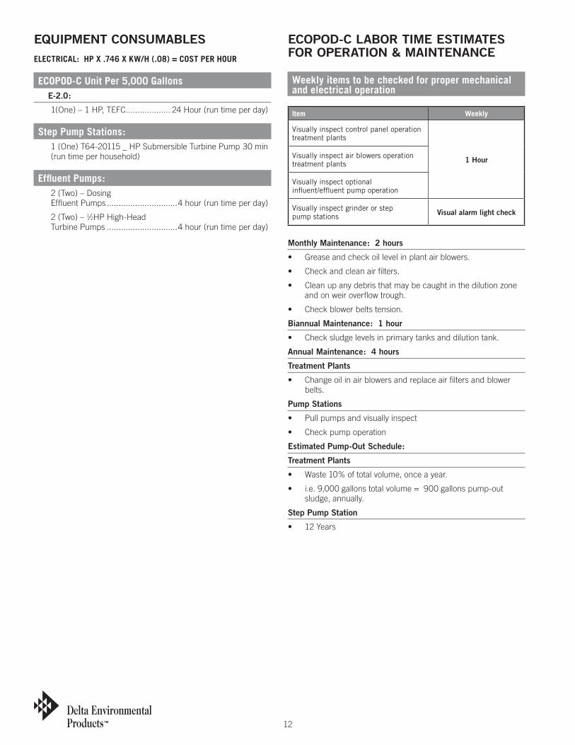
EQUIPMEnT COnSUMablESELECTRICAL: HP x .746 x KW/H (.08) = COST PER HOUR
ECOPOD-C Unit Per 5,000 Gallons E-2.0:
1(One) – 1 HP, TEFC ................... 24 Hour (run time per day)
Step Pump Stations: 1 (One) T64-20115 _ HP Submersible Turbine Pump 30 min
(run time per household)
Effluent Pumps: 2 (Two) – Dosing
Effluent Pumps ..............................4 hour (run time per day)
2 (Two) – 1⁄2HP High-Head Turbine Pumps ..............................4 hour (run time per day)
ECOPOD-C labOR TIME ESTIMaTES FOR OPERaTIOn & MaInTEnanCE
Weekly items to be checked for proper mechanical and electrical operation
Monthly Maintenance: 2 hours
• Greaseandcheckoillevelinplantairblowers.
• Checkandcleanairfilters.
• Cleanupanydebristhatmaybecaughtinthedilutionzoneand on weir overflow trough.
• Checkblowerbeltstension.
biannual Maintenance: 1 hour
• Checksludgelevelsinprimarytanksanddilutiontank.
annual Maintenance: 4 hours
Treatment Plants
• Changeoilinairblowersandreplaceairfiltersandblowerbelts.
Pump Stations
• Pullpumpsandvisuallyinspect
• Checkpumpoperation
Estimated Pump-Out Schedule:
Treatment Plants
• Waste10%oftotalvolume,onceayear.
• i.e.9,000gallonstotalvolume=900gallonspump-outsludge, annually.
Step Pump Station
• 12Years
Item Weekly
Visually inspect control panel operation treatment plants
1 HourVisually inspect air blowers operation treatment plants
Visually inspect optional influent/effluent pump operation
Visually inspect grinder or step pump stations Visual alarm light check
13
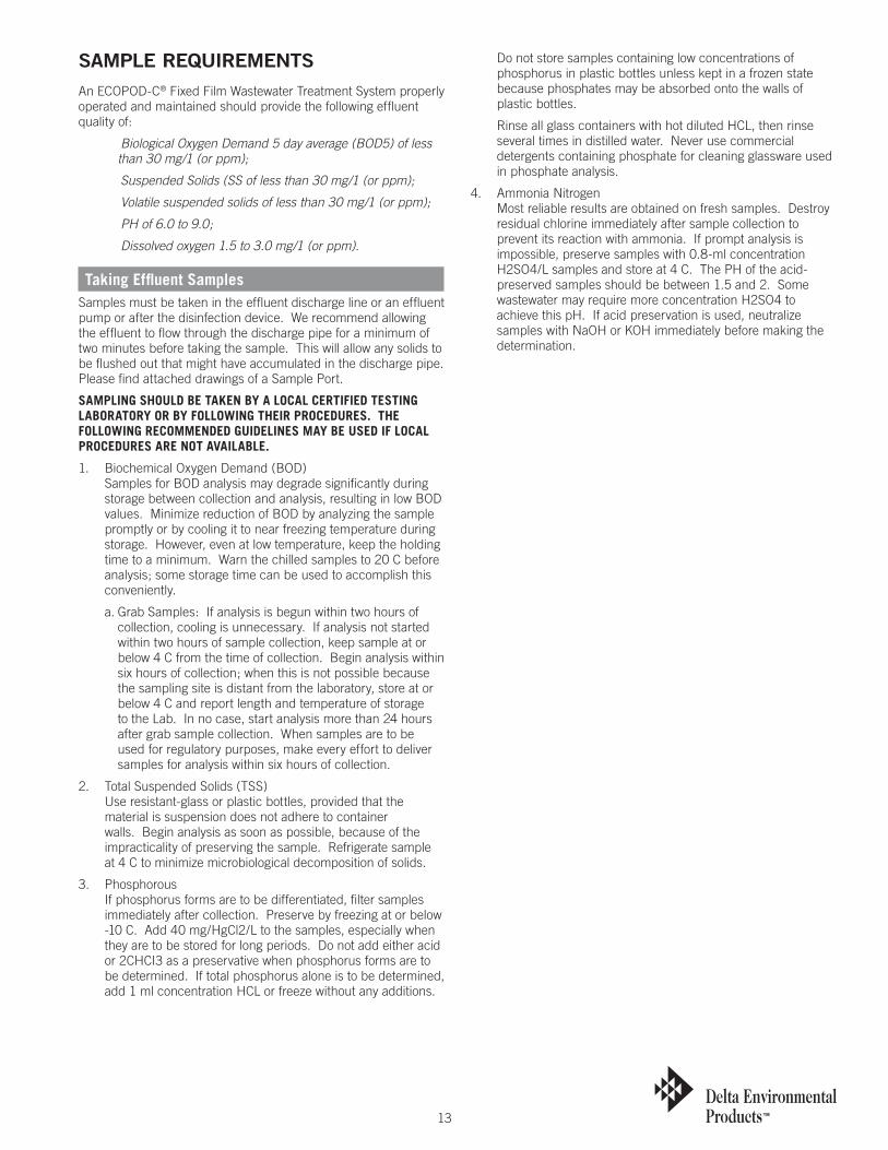
SaMPlE REQUIREMEnTSAn ECOPOD-C® Fixed Film Wastewater Treatment System properly operated and maintained should provide the following effluent quality of:
Biological Oxygen Demand 5 day average (BOD5) of less than 30 mg/1 (or ppm);
Suspended Solids (SS of less than 30 mg/1 (or ppm);
Volatile suspended solids of less than 30 mg/1 (or ppm);
PH of 6.0 to 9.0;
Dissolved oxygen 1.5 to 3.0 mg/1 (or ppm).
Taking Effluent SamplesSamples must be taken in the effluent discharge line or an effluent pump or after the disinfection device. We recommend allowing the effluent to flow through the discharge pipe for a minimum of two minutes before taking the sample. This will allow any solids to be flushed out that might have accumulated in the discharge pipe. Please find attached drawings of a Sample Port.
SAMPLING SHOULD BE TAKEN BY A LOCAL CERTIFIED TESTING LABORATORY OR BY FOLLOWING THEIR PROCEDURES. THE FOLLOWING RECOMMENDED GUIDELINES MAY BE USED IF LOCAL PROCEDURES ARE NOT AVAILABLE.
1. Biochemical Oxygen Demand (BOD) Samples for BOD analysis may degrade significantly during storage between collection and analysis, resulting in low BOD values. Minimize reduction of BOD by analyzing the sample promptly or by cooling it to near freezing temperature during storage. However, even at low temperature, keep the holding time to a minimum. Warn the chilled samples to 20 C before analysis; some storage time can be used to accomplish this conveniently.
a. Grab Samples: If analysis is begun within two hours of collection, cooling is unnecessary. If analysis not started within two hours of sample collection, keep sample at or below 4 C from the time of collection. Begin analysis within six hours of collection; when this is not possible because the sampling site is distant from the laboratory, store at or below 4 C and report length and temperature of storage to the Lab. In no case, start analysis more than 24 hours after grab sample collection. When samples are to be used for regulatory purposes, make every effort to deliver samples for analysis within six hours of collection.
2. Total Suspended Solids (TSS) Use resistant-glass or plastic bottles, provided that the material is suspension does not adhere to container walls. Begin analysis as soon as possible, because of the impracticality of preserving the sample. Refrigerate sample at 4 C to minimize microbiological decomposition of solids.
3. Phosphorous If phosphorus forms are to be differentiated, filter samples immediately after collection. Preserve by freezing at or below -10 C. Add 40 mg/HgCl2/L to the samples, especially when they are to be stored for long periods. Do not add either acid or 2CHCI3 as a preservative when phosphorus forms are to be determined. If total phosphorus alone is to be determined, add 1 ml concentration HCL or freeze without any additions.
Do not store samples containing low concentrations of phosphorus in plastic bottles unless kept in a frozen state because phosphates may be absorbed onto the walls of plastic bottles.
Rinse all glass containers with hot diluted HCL, then rinse several times in distilled water. Never use commercial detergents containing phosphate for cleaning glassware used in phosphate analysis.
4. Ammonia Nitrogen Most reliable results are obtained on fresh samples. Destroy residual chlorine immediately after sample collection to prevent its reaction with ammonia. If prompt analysis is impossible, preserve samples with 0.8-ml concentration H2SO4/L samples and store at 4 C. The PH of the acid-preserved samples should be between 1.5 and 2. Some wastewater may require more concentration H2SO4 to achieve this pH. If acid preservation is used, neutralize samples with NaOH or KOH immediately before making the determination.
14
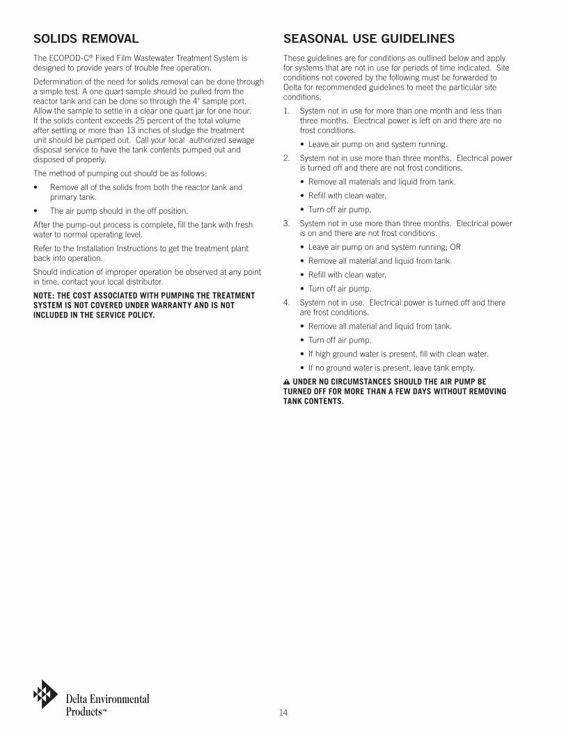
SOlIDS REMOValThe ECOPOD-C® Fixed Film Wastewater Treatment System is designed to provide years of trouble free operation.
Determination of the need for solids removal can be done through a simple test. A one quart sample should be pulled from the reactor tank and can be done so through the 4" sample port. Allow the sample to settle in a clear one quart jar for one hour. If the solids content exceeds 25 percent of the total volume after settling or more than 13 inches of sludge the treatment unit should be pumped out. Call your local authorized sewage disposal service to have the tank contents pumped out and disposed of properly.
The method of pumping out should be as follows:
• Removeallofthesolidsfromboththereactortankandprimary tank.
• Theairpumpshouldintheoffposition.
After the pump-out process is complete, fill the tank with fresh water to normal operating level.
Refer to the Installation Instructions to get the treatment plant back into operation.
Should indication of improper operation be observed at any point in time, contact your local distributor.
NOTE: THE COST ASSOCIATED WITH PUMPING THE TREATMENT SYSTEM IS NOT COVERED UNDER WARRANTY AND IS NOT INCLUDED IN THE SERVICE POLICY.
SEaSOnal USE GUIDElInESThese guidelines are for conditions as outlined below and apply for systems that are not in use for periods of time indicated. Site conditions not covered by the following must be forwarded to Delta for recommended guidelines to meet the particular site conditions.
1. System not in use for more than one month and less than three months. Electrical power is left on and there are no frost conditions.
• Leaveairpumponandsystemrunning.
2. System not in use more than three months. Electrical power is turned off and there are not frost conditions.
• Removeallmaterialsandliquidfromtank.
• Refillwithcleanwater.
• Turnoffairpump.
3. System not in use more than three months. Electrical power is on and there are not frost conditions.
• Leaveairpumponandsystemrunning;OR
• Removeallmaterialandliquidfromtank.
• Refillwithcleanwater.
• Turnoffairpump.
4. System not in use. Electrical power is turned off and there are frost conditions.
• Removeallmaterialandliquidfromtank.
• Turnoffairpump.
• Ifhighgroundwaterispresent,fillwithcleanwater.
• Ifnogroundwaterispresent,leavetankempty.
n UNDER NO CIRCUMSTANCES SHOULD THE AIR PUMP BE TURNED OFF FOR MORE THAN A FEW DAYS WITHOUT REMOVING TANK CONTENTS.
15
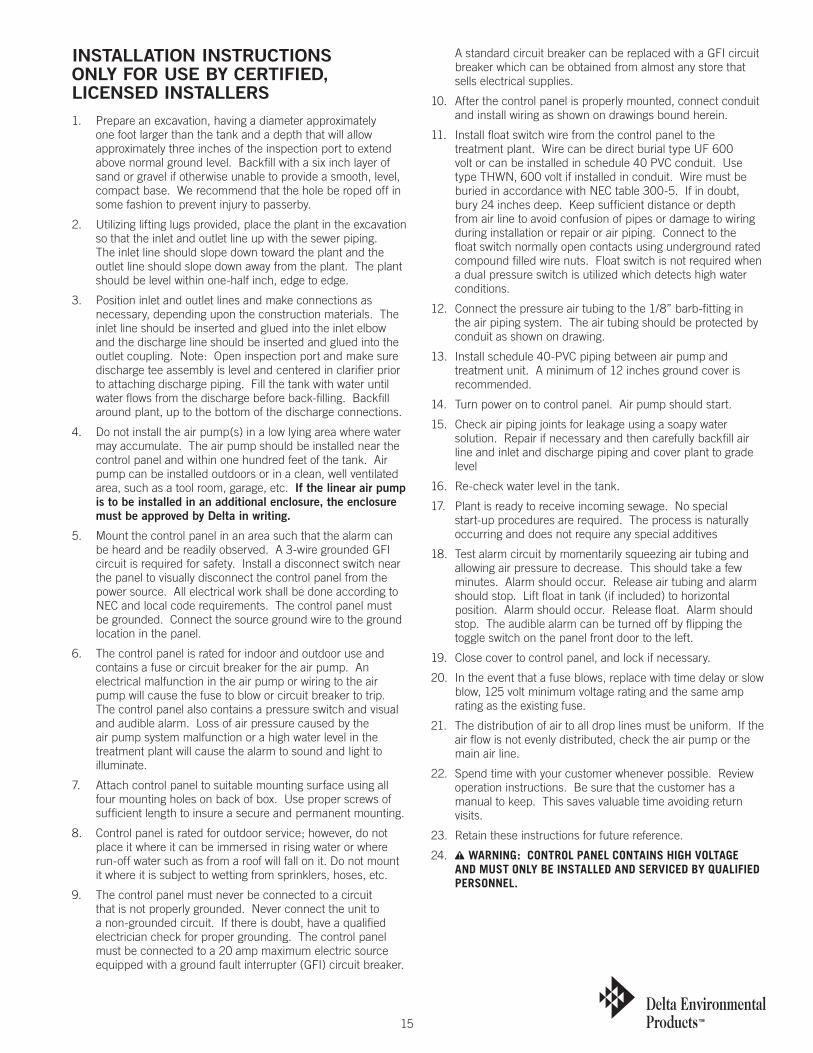
InSTallaTIOn InSTRUCTIOnS OnlY FOR USE bY CERTIFIED, lICEnSED InSTallERS 1. Prepare an excavation, having a diameter approximately
one foot larger than the tank and a depth that will allow approximately three inches of the inspection port to extend above normal ground level. Backfill with a six inch layer of sand or gravel if otherwise unable to provide a smooth, level, compact base. We recommend that the hole be roped off in some fashion to prevent injury to passerby.
2. Utilizing lifting lugs provided, place the plant in the excavation so that the inlet and outlet line up with the sewer piping. The inlet line should slope down toward the plant and the outlet line should slope down away from the plant. The plant should be level within one-half inch, edge to edge.
3. Position inlet and outlet lines and make connections as necessary, depending upon the construction materials. The inlet line should be inserted and glued into the inlet elbow and the discharge line should be inserted and glued into the outlet coupling. Note: Open inspection port and make sure discharge tee assembly is level and centered in clarifier prior to attaching discharge piping. Fill the tank with water until water flows from the discharge before back-filling. Backfill around plant, up to the bottom of the discharge connections.
4. Do not install the air pump(s) in a low lying area where water may accumulate. The air pump should be installed near the control panel and within one hundred feet of the tank. Air pump can be installed outdoors or in a clean, well ventilated area, such as a tool room, garage, etc. If the linear air pump is to be installed in an additional enclosure, the enclosure must be approved by Delta in writing.
5. Mount the control panel in an area such that the alarm can be heard and be readily observed. A 3-wire grounded GFI circuit is required for safety. Install a disconnect switch near the panel to visually disconnect the control panel from the power source. All electrical work shall be done according to NEC and local code requirements. The control panel must be grounded. Connect the source ground wire to the ground location in the panel.
6. The control panel is rated for indoor and outdoor use and contains a fuse or circuit breaker for the air pump. An electrical malfunction in the air pump or wiring to the air pump will cause the fuse to blow or circuit breaker to trip. The control panel also contains a pressure switch and visual and audible alarm. Loss of air pressure caused by the air pump system malfunction or a high water level in the treatment plant will cause the alarm to sound and light to illuminate.
7. Attach control panel to suitable mounting surface using all four mounting holes on back of box. Use proper screws of sufficient length to insure a secure and permanent mounting.
8. Control panel is rated for outdoor service; however, do not place it where it can be immersed in rising water or where run-off water such as from a roof will fall on it. Do not mount it where it is subject to wetting from sprinklers, hoses, etc.
9. The control panel must never be connected to a circuit that is not properly grounded. Never connect the unit to a non-grounded circuit. If there is doubt, have a qualified electrician check for proper grounding. The control panel must be connected to a 20 amp maximum electric source equipped with a ground fault interrupter (GFI) circuit breaker.
A standard circuit breaker can be replaced with a GFI circuit breaker which can be obtained from almost any store that sells electrical supplies.
10. After the control panel is properly mounted, connect conduit and install wiring as shown on drawings bound herein.
11. Install float switch wire from the control panel to the treatment plant. Wire can be direct burial type UF 600 volt or can be installed in schedule 40 PVC conduit. Use type THWN, 600 volt if installed in conduit. Wire must be buried in accordance with NEC table 300-5. If in doubt, bury 24 inches deep. Keep sufficient distance or depth from air line to avoid confusion of pipes or damage to wiring during installation or repair or air piping. Connect to the float switch normally open contacts using underground rated compound filled wire nuts. Float switch is not required when a dual pressure switch is utilized which detects high water conditions.
12. Connect the pressure air tubing to the 1/8” barb-fitting in the air piping system. The air tubing should be protected by conduit as shown on drawing.
13. Install schedule 40-PVC piping between air pump and treatment unit. A minimum of 12 inches ground cover is recommended.
14. Turn power on to control panel. Air pump should start.
15. Check air piping joints for leakage using a soapy water solution. Repair if necessary and then carefully backfill air line and inlet and discharge piping and cover plant to grade level
16. Re-check water level in the tank.
17. Plant is ready to receive incoming sewage. No special start-up procedures are required. The process is naturally occurring and does not require any special additives
18. Test alarm circuit by momentarily squeezing air tubing and allowing air pressure to decrease. This should take a few minutes. Alarm should occur. Release air tubing and alarm should stop. Lift float in tank (if included) to horizontal position. Alarm should occur. Release float. Alarm should stop. The audible alarm can be turned off by flipping the toggle switch on the panel front door to the left.
19. Close cover to control panel, and lock if necessary.
20. In the event that a fuse blows, replace with time delay or slow blow, 125 volt minimum voltage rating and the same amp rating as the existing fuse.
21. The distribution of air to all drop lines must be uniform. If the air flow is not evenly distributed, check the air pump or the main air line.
22. Spend time with your customer whenever possible. Review operation instructions. Be sure that the customer has a manual to keep. This saves valuable time avoiding return visits.
23. Retain these instructions for future reference.
24. n WARNING: CONTROL PANEL CONTAINS HIGH VOLTAGE AND MUST ONLY BE INSTALLED AND SERVICED BY QUALIFIED PERSONNEL.
16
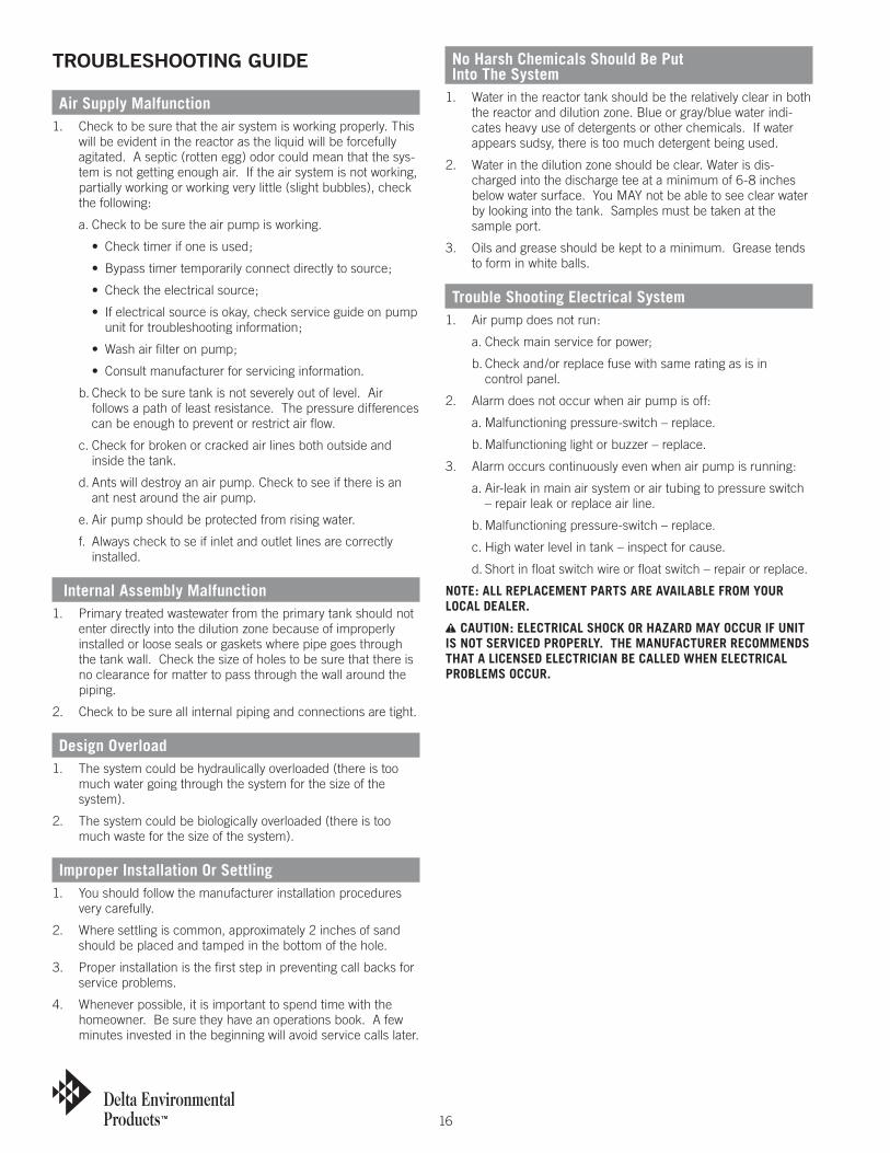
TROUblESHOOTInG GUIDE
Air Supply Malfunction1. Check to be sure that the air system is working properly. This
will be evident in the reactor as the liquid will be forcefully agitated. A septic (rotten egg) odor could mean that the sys-tem is not getting enough air. If the air system is not working, partially working or working very little (slight bubbles), check the following:
a. Check to be sure the air pump is working.
• Checktimerifoneisused;
• Bypasstimertemporarilyconnectdirectlytosource;
• Checktheelectricalsource;
• Ifelectricalsourceisokay,checkserviceguideonpumpunit for troubleshooting information;
• Washairfilteronpump;
• Consultmanufacturerforservicinginformation.
b. Check to be sure tank is not severely out of level. Air follows a path of least resistance. The pressure differences can be enough to prevent or restrict air flow.
c. Check for broken or cracked air lines both outside and inside the tank.
d. Ants will destroy an air pump. Check to see if there is an ant nest around the air pump.
e. Air pump should be protected from rising water.
f. Always check to se if inlet and outlet lines are correctly installed.
Internal Assembly Malfunction1. Primary treated wastewater from the primary tank should not
enter directly into the dilution zone because of improperly installed or loose seals or gaskets where pipe goes through the tank wall. Check the size of holes to be sure that there is no clearance for matter to pass through the wall around the piping.
2. Check to be sure all internal piping and connections are tight.
Design Overload1. The system could be hydraulically overloaded (there is too
much water going through the system for the size of the system).
2. The system could be biologically overloaded (there is too much waste for the size of the system).
Improper Installation Or Settling1. You should follow the manufacturer installation procedures
very carefully.
2. Where settling is common, approximately 2 inches of sand should be placed and tamped in the bottom of the hole.
3. Proper installation is the first step in preventing call backs for service problems.
4. Whenever possible, it is important to spend time with the homeowner. Be sure they have an operations book. A few minutes invested in the beginning will avoid service calls later.
No Harsh Chemicals Should Be Put Into The System
1. Water in the reactor tank should be the relatively clear in both the reactor and dilution zone. Blue or gray/blue water indi-cates heavy use of detergents or other chemicals. If water appears sudsy, there is too much detergent being used.
2. Water in the dilution zone should be clear. Water is dis-charged into the discharge tee at a minimum of 6-8 inches below water surface. You MAY not be able to see clear water by looking into the tank. Samples must be taken at the sample port.
3. Oils and grease should be kept to a minimum. Grease tends to form in white balls.
Trouble Shooting Electrical System1. Air pump does not run:
a. Check main service for power;
b. Check and/or replace fuse with same rating as is in control panel.
2. Alarm does not occur when air pump is off:
a. Malfunctioning pressure-switch – replace.
b. Malfunctioning light or buzzer – replace.
3. Alarm occurs continuously even when air pump is running:
a. Air-leak in main air system or air tubing to pressure switch – repair leak or replace air line.
b. Malfunctioning pressure-switch – replace.
c. High water level in tank – inspect for cause.
d. Short in float switch wire or float switch – repair or replace.
NOTE: ALL REPLACEMENT PARTS ARE AVAILABLE FROM YOUR LOCAL DEALER.
n CAUTION: ELECTRICAL SHOCK OR HAzARD MAY OCCUR IF UNIT IS NOT SERVICED PROPERLY. THE MANUFACTURER RECOMMENDS THAT A LICENSED ELECTRICIAN BE CALLED WHEN ELECTRICAL PROBLEMS OCCUR.
17
COMPOnEnT REPlaCEMEnT PROCEDURE1. Air Pump – Follow same procedure as outlined in the
“Installation Instructions”.
2. Float Switch – Remove Treatment Plant’s Riser or 24 inch cover. Locate float switch cable. Untie know. Cut float switch cable. Slip float switch cable through rubber grommet into the plant. Replace with exact replacement float switch. Reinstall by reversing procedure. Reconnect float switch wires using Underground Rated Compound filled wire nuts. See Float Switch Mounting Detail.
3. Pressure Switch – Turn all power off to control panel. Remove screws securing pressure switch as well as connectors and tubing. Reverse procedure to install new pressure switch.
4. Buzzer – Turn all power off to control panel. Remove screw attaching buzzer to back plate as well as connectors. Reverse procedure to install new buzzer.
5. Lamp-holder – Turn all power off to control panel. Remove lock nut securing lamp-holder to door as well as connectors. Remove lamp-holder. Install new lamp-holder with gaskets furnished. Continue with reverse procedure.
6. Lamp – Turn all power off to control panel. Remove red lamp cover from front of control panel. Remove and replace lamp which is a push in type. Replace lamp cover and cover gasket.
7. Fuse – Turn all power off to control panel. Pull top of fuse holder outward. Remove and replace fuse. Push fuse back into place.
8. Buzzer Switch – Turn all power off to control panel. Remove rubber boot on switch. Remove hex nut from switch on panel front as well as connectors on switch. Reverse procedure to install new switch.
GEnERal COMMEnTS1. Only factory approved equipment can be used for replace-
ment on individual treatment systems.
2. If the decision is made to pump out a system, be sure to contact a licensed waste hauler.
3. If a chronic problem develops and all items listed have been checked, consult with the factory.
4. Taking pictures of systems when troubleshooting will help document activity in the field.
5. Keep good records.
NOTE: IF THE ENTIRE COVER NEEDS TO BE REMOVED ON ANY ONE OF THE VARIOUS MODEL TREATMENT PLANTS, THE ExISTING SILICONE OR STRIP SEAL MUST BE REMOVED AND REPLACED WITH A NEW ONE. THIS WILL PROVIDE A POSITIVE SEAL WHICH WILL NOT ALLOW ANY INFILTRATION INTO OR OUT OF THE TREATMENT PLANT.
18
P. O
. BO
X 96
9 D
ENH
AM
SPR
ING
S, L
A 7
0727
DEL
TA E
NVI
RON
MEN
TAL
PRO
DU
CTS
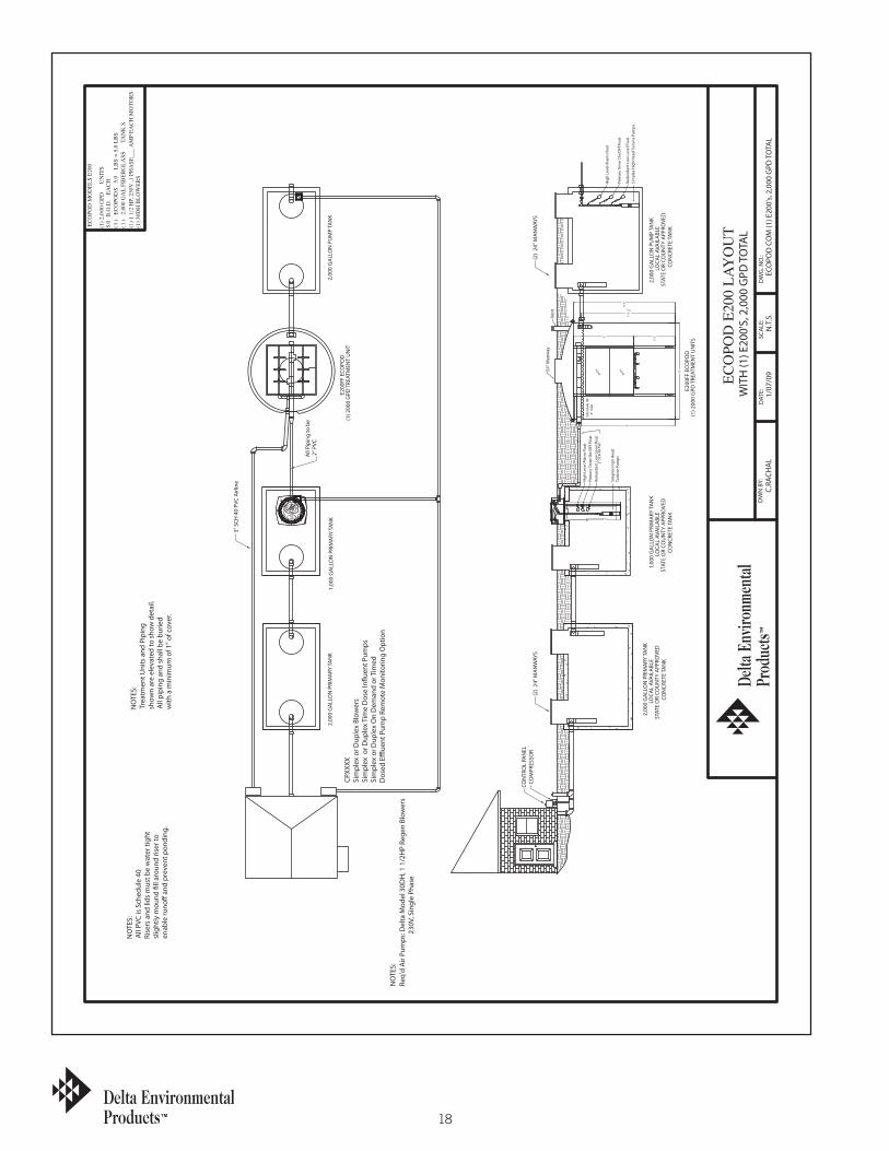
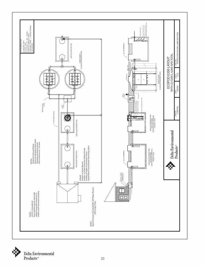
ECO
POD
MO
DEL
S E2
00
(1) 2
,000
GPD
U
NIT
S5.
0 B
.O.D
. E
AC
H
(1)
ECO
POD
S 5.
0 LB
S =
5.0
LBS
(1)
2,80
0 G
AL
FIB
ERG
LASS
TA
NK
S
(1) 3
0DH
BLO
WER
S
ECO
POD
E20
0 LA
YO
UT
DW
N B
Y:C.
RACH
AL
ECO
POD
CO
M (1
) E20
0's,
2,00
0 G
PD T
OTA
LN
.T.S
.1/
07/0
9D
ATE:
SCA
LE:
DW
G. N
O.:
WIT
H (1
) E20
0'S,
2,0
00 G
PD T
OTA
L
Vent
24" M
anw
ay
Sche
dule
40
4" I
nlet
2" S
CH 4
0 PV
C
Ø26.62
E200
FF E
COPO
D(1
) 200
0 G
PD T
REAT
MEN
T U
NIT
CON
CRET
E TA
NK
1,00
0 G
ALL
ON
PRI
MA
RY TA
NK
LOCA
L AV
AIL
ABL
E ST
ATE
OR
COU
NTY
APP
ROVE
D
(1) 2
000
GPD
TRE
ATM
ENT
UN
ITS
3" S
CH 4
0 PV
C A
irlin
e
E200
FF E
COPO
D
CON
TRO
L PA
NEL
COM
PRES
SOR
(2)
24" M
AN
WAY
S
STAT
E O
R CO
UN
TY A
PPRO
VED
LOCA
L AV
AIL
ABL
E 2,
000
GA
LLO
N P
RIM
ARY
TAN
K
CON
CRET
E TA
NK
All
Pipi
ng to
be
2" P
VC
1,00
0 G
ALL
ON
PRI
MA
RY TA
NK
2,00
0 G
ALL
ON
PRI
MA
RY TA
NK
Redu
ndan
t Low
Lev
el F
loat
Prim
ary
Tim
er O
n/O
Ff F
loat
Hig
h Le
vel A
larm
Flo
at
Sim
plex
Hig
h H
ead
Turb
ine
Pum
ps
(2)
24" M
AN
WAY
S
2,00
0 G
ALL
ON
PU
MP
TAN
K
Sim
plex
Hig
h H
ead
Turb
ine
Pum
ps
Hig
h Le
vel A
larm
Flo
at
Prim
ary
Tim
er O
n/O
Ff F
loat
Redu
ndan
t Low
Lev
el F
loat
STAT
E O
R CO
UN
TY A
PPRO
VED
LOCA
L AV
AIL
ABL
E 2,
000
GA
LLO
N P
UM
P TA
NK
CON
CRET
E TA
NK
NO
TES:
Trea
tmen
t Uni
ts a
nd P
ipin
g sh
own
are
elev
ated
to s
how
det
ail.
All
pipi
ng a
nd s
hall
be b
urie
dw
ith a
min
imum
of 1
" of c
over
.
NO
TES:
All
PVC
is S
ched
ule
40Ri
sers
and
lids
mus
t be
wat
er ti
ght
slig
htly
mou
nd �
ll ar
ound
rise
r to
enab
le ru
no�
and
prev
ent p
ondi
ng.
NO
TES:
Req'
d A
ir Pu
mps
: Del
ta M
odel
30D
H, 1
1/2
HP
Rege
n Bl
ower
s
2
30V,
Sin
gle
Phas
e
CPXX
XXSi
mpl
ex o
r Dup
lex
Blow
ers
Sim
plex
or D
uple
x Ti
me
Dos
e In
�uen
t Pum
psSi
mpl
ex o
r Dup
lex
On
Dem
and
or T
imed
Dos
ed E
�ue
nt P
ump
Rem
ote
Mon
itorin
g O
ptio
n
3'-5
"5'
MED
IA
8'
8'
8'-6
"7'
-91 2
"
MED
IA
(1) 1
1/2
HP,
230
V ,1
PH
ASE
___
AM
P EA
CH
MO
TOR
S
19
DEL
TA E
NVI
RON
MEN
TAL
PRO
DU
CTS
P. O
. BO
X 96
9 D
ENH
AM
SPR
ING
S, L
A 7
0727
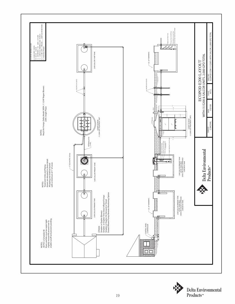
WIT
H (1
) E20
0 &
SA
LCO
R U
NIT
S, 2
,000
GPD
TO
TAL
DW
G. N
O.:
SCA
LE:
DAT
E: 1/07
/09
N.T
.S.
ECO
POD
CO
M (1
) E20
0's W
ITH
SA
LCO
R, 2
,000
GPD
TO
TAL
C.RA
CHA
LD
WN
BY:
ECO
POD
E20
0 LA
YO
UT(1
) 2,0
00 G
PD U
NIT
S5.
0 B
.O.D
. E
AC
H
(1)
ECO
POD
S 5.
0 LB
S =
5.0
LBS
(1)
2,80
0 G
AL
FIB
ERG
LASS
TA
NK
S (1
) 1 1
/2 H
P, 2
30V
,1 P
HA
SE__
_ A
MP
EAC
H M
OTO
RS
(1
) 30D
H B
LOW
ERS
ECO
POD
MO
DEL
S E2
00
Ø26.62
2" S
CH 4
0 PV
C
Sche
dule
40
4" I
nlet
24" M
anw
ayVe
nt
SALC
OR
3G U
V LI
GH
TS
Redu
ndan
t Low
Lev
el F
loat
Prim
ary
Tim
er O
n/O
Ff F
loat
Hig
h Le
vel A
larm
Flo
at
Sim
plex
Hig
h H
ead
Turb
ine
Pum
ps
2,00
0 G
ALL
ON
PU
MP
TAN
K
(2)
24" M
AN
WAY
S
Sim
plex
Hig
h H
ead
Turb
ine
Pum
ps
Hig
h Le
vel A
larm
Flo
atPr
imar
y Ti
mer
On/
OFf
Flo
atRe
dund
ant L
ow L
evel
Flo
at
2,00
0 G
ALL
ON
PRI
MA
RY TA
NK
1,00
0 G
ALL
ON
PRI
MA
RY TA
NK
All
Pipi
ng to
be
2" P
VC
CON
CRET
E TA
NK
2,00
0 G
ALL
ON
PRI
MA
RY TA
NK
LOCA
L AV
AIL
ABL
E ST
ATE
OR
COU
NTY
APP
ROVE
D
(2)
24" M
AN
WAY
SCO
MPR
ESSO
RCO
NTR
OL
PAN
EL
E200
FF E
COPO
D
3" S
CH 4
0 PV
C A
irlin
e
(1) 2
000
GPD
TRE
ATM
ENT
UN
ITS
STAT
E O
R CO
UN
TY A
PPRO
VED
LOCA
L AV
AIL
ABL
E 1,
000
GA
LLO
N P
RIM
ARY
TAN
K
CON
CRET
E TA
NK
(1) 2
000
GPD
TRE
ATM
ENT
UN
ITE2
00FF
ECO
POD
SALC
OR
3G U
V LI
GH
TS
CPXX
XXSi
mpl
ex o
r Dup
lex
Blow
ers
Sim
plex
or D
uple
x Ti
me
Dos
e In
�uen
t Pum
psSi
mpl
ex o
r Dup
lex
On
Dem
and
or T
imed
Dos
ed E
�ue
nt P
ump
Rem
ote
Mon
itorin
g O
ptio
n
NO
TES:
Req'
d A
ir Pu
mps
: Del
ta M
odel
30D
H, 1
1/2
HP
Rege
n Bl
ower
s
2
30V,
Sin
gle
Phas
e
NO
TES:
All
PVC
is S
ched
ule
40Ri
sers
and
lids
mus
t be
wat
er ti
ght
slig
htly
mou
nd �
ll ar
ound
rise
r to
enab
le ru
no�
and
prev
ent p
ondi
ng.
NO
TES:
Trea
tmen
t Uni
ts a
nd P
ipin
g sh
own
are
elev
ated
to s
how
det
ail.
All
pipi
ng a
nd s
hall
be b
urie
dw
ith a
min
imum
of 1
" of c
over
.
MED
IA
7'-9
9 16"
8'-6
"
8'
8'-0
3 16"
MED
IA
60.0
000
41.0
591
20
P. O
. BO
X 96
9 D
ENH
AM
SPR
ING
S, L
A 7
0727
DEL
TA E
NVI
RON
MEN
TAL
PRO
DU
CTS
ECO
POD
MO
DEL
S E2
00
(2) 2
,000
GPD
U
NIT
S5.
0 B
.O.D
. E
ACH
(2
) ECO
POD
S
5.0
LBS
= 1
0.0
LBS
(2) 2
,800
GA
L FI
BERG
LASS
TAN
KS
(1) 3
HP,
230
V ,1
PH
ASE
__
_ A
MP
EACH
MO
TORS
(1
) K05
BLO
WER
S
ECO
POD
E20
0 LA
YOU
T
DW
N B
Y:C.
RACH
AL
ECO
POD
CO
M (2
) E20
0's,
4,00
0 G
PD T
OTA
LN
.T.S
.1/
07/0
9D
ATE:
SCA
LE:
DW
G. N
O.:
WIT
H (2
) E20
0'S,
4,0
00 G
PD T
OTA
L
UTI
LITY
BOX
WIT
HZO
NER
UTI
LITY
BOX
WIT
HZO
NER
Vent
24" M
anw
ay
Sche
dule
40
4" I
nlet
2" S
CH 4
0 PV
C
Ø26.62
1 31 41 1
2
34
211
19 8 67
0 5
E200
FF E
COPO
D(2
) 200
0 G
PD T
REAT
MEN
T U
NIT
S
CON
CRET
E TA
NK
2,00
0 G
ALL
ON
PRI
MA
RY TA
NK
LOCA
L AV
AIL
ABL
E ST
ATE
OR
COU
NTY
APP
ROVE
D
(2) 2
000
GPD
TRE
ATM
ENT
UN
ITS
3" S
CH 4
0 PV
C A
irlin
e
E200
FF E
COPO
D
CON
TRO
L PA
NEL
COM
PRES
SOR
(2)
24" M
AN
WAY
S
STAT
E O
R CO
UN
TY A
PPRO
VED
LOCA
L AV
AIL
ABL
E 4,
000
GA
LLO
N P
RIM
ARY
TAN
K
CON
CRET
E TA
NK
All
Pipi
ng to
be
2" P
VC
2,00
0 G
ALL
ON
PRI
MA
RY TA
NK
4,00
0 G
ALL
ON
PRI
MA
RY TA
NK
Redu
ndan
t Low
Lev
el F
loat
Prim
ary
Tim
er O
n/O
Ff F
loat
Hig
h Le
vel A
larm
Flo
at
Sim
plex
Hig
h H
ead
Turb
ine
Pum
ps
(2)
24" M
AN
WAY
S
4,00
0 G
ALL
ON
PU
MP
TAN
K
Sim
plex
Hig
h H
ead
Turb
ine
Pum
ps
Hig
h Le
vel A
larm
Flo
at
Prim
ary
Tim
er O
n/O
Ff F
loat
Redu
ndan
t Low
Lev
el F
loat
NO
TES:
Trea
tmen
t Uni
ts a
nd P
ipin
g sh
own
are
elev
ated
to s
how
det
ail.
All
pipi
ng a
nd s
hall
be b
urie
dw
ith a
min
imum
of 1
" of c
over
.
NO
TES:
All
PVC
is S
ched
ule
40Ri
sers
and
lids
mus
t be
wat
er ti
ght
slig
htly
mou
nd �
ll ar
ound
rise
r to
enab
le ru
no�
and
prev
ent p
ondi
ng.
NO
TES:
Req'
d A
ir Pu
mps
: Del
ta M
odel
K05
, 3H
P Re
gen
Blow
ers
230
V, S
ingl
e Ph
ase
CPXX
XXSi
mpl
ex o
r Dup
lex
Blow
ers
Sim
plex
or D
uple
x Ti
me
Dos
e In
�uen
t Pum
psSi
mpl
ex o
r Dup
lex
On
Dem
and
or T
imed
Dos
ed E
�ue
nt P
ump
Rem
ote
Mon
itorin
g O
ptio
n
3'-5
"5'
MED
IA
8'
8'
8'-6
"7'
-91 2
"
MED
IA

21
ECO
POD
MO
DEL
S E2
00
(3) 2
,000
GPD
UN
ITS
5.0
B.O
.D.
EAC
H
(3)
ECO
POD
S
5.0
LBS
= 1
5.00
LBS
(3
) 2,
800
GA
L FI
BERG
LASS
TAN
KS
(1) 3
HP,
230
V ,1
PH
ASE
__
_ A
MP
EACH
MO
TORS
(1
) K05
BLO
WER
S
ECO
POD
E20
0 LA
YOU
T
DW
N B
Y:C.
RACH
AL
ECO
POD
CO
M (3
) E20
0's,
6,00
0 G
PD T
OTA
LN
.T.S
.1/
07/0
9D
ATE:
SCA
LE:
DW
G. N
O.:
WIT
H (3
) E20
0'S,
6,0
00 G
PD T
OTA
L
UTI
LITY
BOX
WIT
HZO
NER
UTI
LITY
BOX
WIT
HZO
NER
Vent
24" M
anw
ay
Sche
dule
40
4" I
nlet
2" S
CH 4
0 PV
C
Ø26.62
1 31 41 1 2
34
211
19 8 67
0 5
E200
FF E
COPO
D(3
) 200
0 G
PD T
REAT
MEN
T U
NIT
S
CON
CRET
E TA
NK
3,00
0 G
ALL
ON
PRI
MA
RY TA
NK
LOCA
L AV
AIL
ABL
E ST
ATE
OR
COU
NTY
APP
ROVE
D
(3) 2
000
GPD
TRE
ATM
ENT
UN
ITS
3" S
CH 4
0 PV
C A
irlin
e
E200
FF E
COPO
D
CON
TRO
L PA
NEL
COM
PRES
SOR
(2)
24" M
AN
WAY
S
STAT
E O
R CO
UN
TY A
PPRO
VED
LOCA
L AV
AIL
ABL
E 6,
000
GA
LLO
N P
RIM
ARY
TAN
K
CON
CRET
E TA
NK
All
Pipi
ng to
be
2" P
VC
3,00
0 G
ALL
ON
PRI
MA
RY TA
NK
6,00
0 G
ALL
ON
PRI
MA
RY TA
NK
Redu
ndan
t Low
Lev
el F
loat
Prim
ary
Tim
er O
n/O
Ff F
loat
Hig
h Le
vel A
larm
Flo
at
Sim
plex
Hig
h H
ead
Turb
ine
Pum
ps
(2)
24" M
AN
WAY
S
4,00
0 G
ALL
ON
PU
MP
TAN
K
Sim
plex
Hig
h H
ead
Turb
ine
Pum
ps
Hig
h Le
vel A
larm
Flo
at
Prim
ary
Tim
er O
n/O
Ff F
loat
Redu
ndan
t Low
Lev
el F
loat
NO
TES:
Trea
tmen
t Uni
ts a
nd P
ipin
g sh
own
are
elev
ated
to s
how
det
ail.
All
pipi
ng a
nd s
hall
be b
urie
dw
ith a
min
imum
of 1
" of c
over
.
NO
TES:
All
PVC
is S
ched
ule
40Ri
sers
and
lids
mus
t be
wat
er ti
ght
slig
htly
mou
nd �
ll ar
ound
rise
r to
enab
le ru
no�
and
prev
ent p
ondi
ng.
NO
TES:
Req'
d A
ir Pu
mps
: Del
ta M
odel
K05
, 3H
P Re
gen
Blow
ers
230
V, S
ingl
e Ph
ase
CPXX
XXSi
mpl
ex o
r Dup
lex
Blow
ers
Sim
plex
or D
uple
x Ti
me
Dos
e In
�uen
t Pum
psSi
mpl
ex o
r Dup
lex
On
Dem
and
or T
imed
Dos
ed E
�ue
nt P
ump
Rem
ote
Mon
itorin
g O
ptio
n
3'-5
"5'
MED
IA
8'
8'
8'-6
"7'
-91 2
"
MED
IA
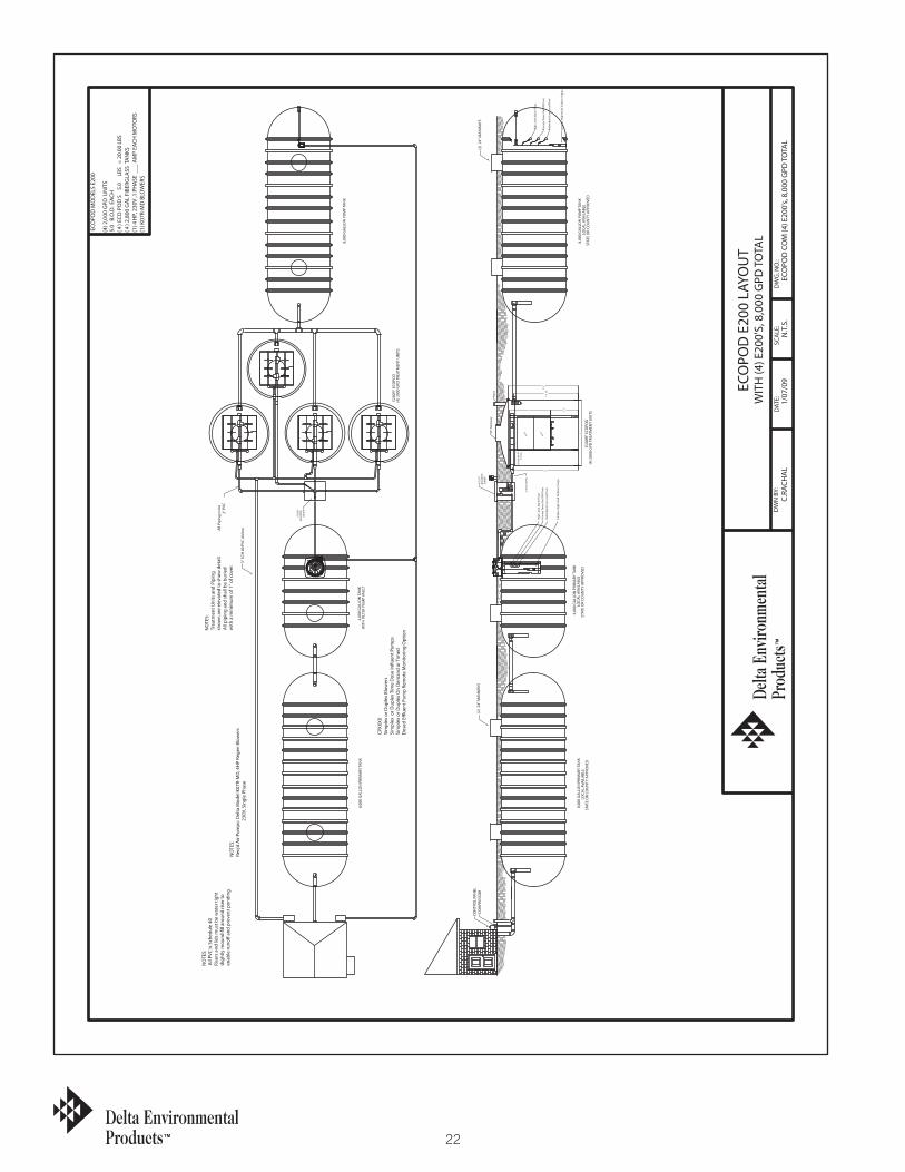
22
P. O
. BO
X 96
9 D
ENH
AM
SPR
ING
S, L
A 7
0727
DEL
TA E
NVI
RON
MEN
TAL
PRO
DU
CTS
ECO
POD
MO
DEL
S E2
00
(4) 2
,000
GPD
UN
ITS
5.0
B.O
.D. E
ACH
(4
) ECO
POD
S
5.0
LBS
= 2
0.00
LBS
(4
) 2,8
00 G
AL
FIBE
RGLA
SS T
AN
KS
(1) 4
HP,
230
V ,1
PH
ASE
__
_ A
MP
EACH
MO
TORS
(1
) K07
R-M
D B
LOW
ERS
ECO
POD
E20
0 LA
YOU
T
DW
N B
Y:C.
RACH
AL
ECO
POD
CO
M (4
) E20
0's,
8,00
0 G
PD T
OTA
LN
.T.S
.1/
07/0
9D
ATE:
SCA
LE:
DW
G. N
O.:
WIT
H (4
) E20
0'S,
8,0
00 G
PD T
OTA
L
UTI
LITY
BOX
WIT
HZO
NER
UTI
LITY
BOX
WIT
HZO
NER
Vent
24" M
anw
ay
Sche
dule
40
4" I
nlet
2" S
CH 4
0 PV
C
Ø26.62
1 31 411 2 34
2 1119 867
0 5
E200
FF E
COPO
D(4
) 200
0 G
PD T
REAT
MEN
T U
NIT
S
4,00
0 G
ALL
ON
PRI
MA
RY TA
NK
LOCA
L AV
AIL
ABL
E ST
ATE
OR
COU
NTY
APP
ROVE
D
(4) 2
000
GPD
TRE
ATM
ENT
UN
ITS
3" S
CH 4
0 PV
C A
irlin
e
E200
FF E
COPO
D
CON
TRO
L PA
NEL
COM
PRES
SOR
(2)
24" M
AN
WAY
S
STAT
E O
R CO
UN
TY A
PPRO
VED
LOCA
L AV
AIL
ABL
E 8,
000
GA
LLO
N P
RIM
ARY
TAN
K
All
Pipi
ng to
be
2" P
VC
4,00
0 G
ALL
ON
TAN
K
Redu
ndan
t Low
Lev
el F
loat
Prim
ary
Tim
er O
n/O
Ff F
loat
Hig
h Le
vel A
larm
Flo
at
Sim
plex
Hig
h H
ead
Turb
ine
Pum
psSi
mpl
ex H
igh
Hea
d Tu
rbin
e Pu
mps
Hig
h Le
vel A
larm
Flo
at
Prim
ary
Tim
er O
n/O
Ff F
loat
Redu
ndan
t Low
Lev
el F
loat
8,00
0 G
ALL
ON
PRI
MA
RY TA
NK
8,00
0 G
ALL
ON
PU
MP
TAN
K
8,00
0 G
ALL
ON
PU
MP
TAN
KLO
CAL
AVA
ILA
BLE
STAT
E O
R CO
UN
TY A
PPRO
VED
(2)
24" M
AN
WAY
S
WIT
H F
ILTE
R PU
MP
VAU
LT
NO
TES:
Trea
tmen
t Uni
ts a
nd P
ipin
g sh
own
are
elev
ated
to s
how
det
ail.
All
pipi
ng a
nd s
hall
be b
urie
dw
ith a
min
imum
of 1
" of c
over
.
NO
TES:
All
PVC
is S
ched
ule
40Ri
sers
and
lids
mus
t be
wat
er ti
ght
slig
htly
mou
nd �
ll ar
ound
rise
r to
enab
le ru
no�
and
prev
ent p
ondi
ng.
NO
TES:
Req'
d A
ir Pu
mps
: Del
ta M
odel
K07
R-M
D, 4
HP
Rege
n Bl
ower
s
2
30V,
Sin
gle
Phas
e
CPXX
XXSi
mpl
ex o
r Dup
lex
Blow
ers
Sim
plex
or D
uple
x Ti
me
Dos
e In
�uen
t Pum
psSi
mpl
ex o
r Dup
lex
On
Dem
and
or T
imed
Dos
ed E
�ue
nt P
ump
Rem
ote
Mon
itorin
g O
ptio
n
3'-5
"
5'
MED
IA
8'
8'
8'-6
"7'
-91 2
"
MED
IA
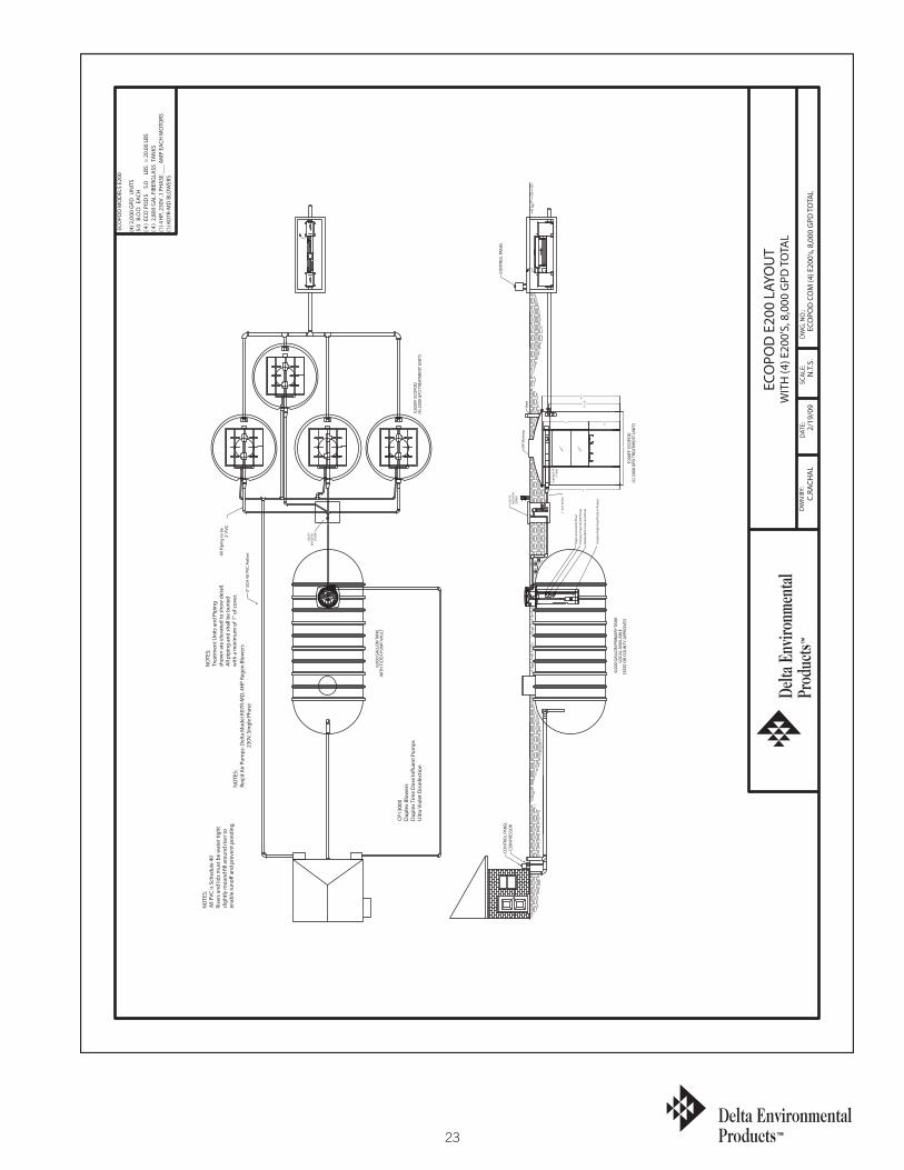
23
ECO
POD
MO
DEL
S E2
00
(4) 2
,000
GPD
UN
ITS
5.0
B.O
.D.
EACH
(4
) EC
OPO
DS
5.
0 LB
S =
20.
00 L
BS
(4)
2,80
0 G
AL
FIBE
RGLA
SS TA
NKS
(1
) 4 H
P, 2
30V
,1 P
HA
SE
___
AM
P EA
CH M
OTO
RS
(1) K
07R-
MD
BLO
WER
S
ECO
POD
E20
0 LA
YOU
T
DW
N B
Y:C.
RACH
AL
ECO
POD
CO
M (4
) E20
0's,
8,00
0 G
PD T
OTA
LN
.T.S
.2/
19/0
9D
ATE:
SCA
LE:
DW
G. N
O.:
WIT
H (4
) E20
0'S,
8,0
00 G
PD T
OTA
L
UTI
LITY
BOX
WIT
HZO
NER
UTI
LITY
BOX
WIT
HZO
NER
Vent
24" M
anw
ay
Sche
dule
40
4" I
nlet
2" S
CH 4
0 PV
C
Ø26.62
1 31 411 2 34
2 1119 867
0 5
FLO
W
FLO
WFL
OW
E200
FF E
COPO
D(4
) 200
0 G
PD T
REAT
MEN
T U
NIT
S
6,00
0 G
ALL
ON
PRI
MA
RY TA
NK
LOCA
L AV
AIL
ABL
E ST
ATE
OR
COU
NTY
APP
ROVE
D
(4) 2
000
GPD
TRE
ATM
ENT
UN
ITS
3" S
CH 4
0 PV
C A
irlin
e
E200
FF E
COPO
D
CON
TRO
L PA
NEL
COM
PRES
SOR
All
Pipi
ng to
be
2" P
VC
6,00
0 G
ALL
ON
TAN
K
Redu
ndan
t Low
Lev
el F
loat
Prim
ary
Tim
er O
n/O
Ff F
loat
Hig
h Le
vel A
larm
Flo
at
Sim
plex
Hig
h H
ead
Turb
ine
Pum
ps
WIT
H F
ILTE
R PU
MP
VAU
LT
CON
TRO
L PA
NEL
NO
TES:
Trea
tmen
t Uni
ts a
nd P
ipin
g sh
own
are
elev
ated
to s
how
det
ail.
All
pipi
ng a
nd s
hall
be b
urie
dw
ith a
min
imum
of 1
" of c
over
.
NO
TES:
All
PVC
is S
ched
ule
40Ri
sers
and
lids
mus
t be
wat
er ti
ght
slig
htly
mou
nd �
ll ar
ound
rise
r to
enab
le ru
no�
and
prev
ent p
ondi
ng.
NO
TES:
Req'
d A
ir Pu
mps
: Del
ta M
odel
K07
R-M
D, 4
HP
Rege
n Bl
ower
s
2
30V,
Sin
gle
Phas
e
CP13
000
Dup
lex
Blow
ers
Dup
lex
Tim
e D
ose
In�u
ent P
umps
U
ltra
Viol
et D
isin
fect
ion
3'-5
"5'
MED
IA
8'
8'
8'-6
"7'
-91 2
"
MED
IA
OU
TLET
INLE
T
TRO
JAN
SYS
TEM
UV
3000
TOP
BOTTOM2
LAMPSTATUS
1

24
50
768911 1
2 4 3
211 41 31
Ø26.62
2" S
CH 4
0 PV
C
Sche
dule
40
4" I
nlet
24" M
anw
ayVe
nt
UTI
LITY
BOX
WIT
HZO
NER
UTI
LITY
BOX
WIT
HZO
NER
WIT
H (5
) E20
0'S,
10,
000
GPD
TO
TAL
DW
G. N
O.:
SCA
LE:
DAT
E: 1/07
/09
N.T
.S.
ECO
POD
CO
M (5
) E20
0's,
8,00
0 G
PD T
OTA
LC.
RACH
AL
DW
N B
Y:
ECO
POD
E20
0 LA
YOU
T
(5) 2
,000
GPD
UN
ITS
5.0
B.O
.D.
EACH
(5
) EC
OPO
DS
5.
0 LB
S =
25.
00 L
BS
(5)
2,80
0 G
AL
FIBE
RGLA
SS T
AN
KS
(1) 5
HP,
230V
,1 P
HA
SE _
__ A
MP
EACH
MO
TORS
(1) K
08R-
MD
BLO
WER
S
ECO
POD
MO
DEL
S E2
00
WIT
H F
ILTE
R PU
MP
VAU
LT
(2)
24" M
AN
WAY
S
STAT
E O
R CO
UN
TY A
PPRO
VED
LOCA
L AV
AIL
ABL
E 10
,000
GA
LLO
N P
UM
P TA
NK
10,0
00 G
ALL
ON
PU
MP
TAN
K
10,0
00 G
ALL
ON
PRI
MA
RY TA
NK
Redu
ndan
t Low
Lev
el F
loat
Prim
ary
Tim
er O
n/O
Ff F
loat
Hig
h Le
vel A
larm
Flo
at
Sim
plex
Hig
h H
ead
Turb
ine
Pum
psSi
mpl
ex H
igh
Hea
d Tu
rbin
e Pu
mps
Hig
h Le
vel A
larm
Flo
atPr
imar
y Ti
mer
On/
OFf
Flo
atRe
dund
ant L
ow L
evel
Flo
at
5,00
0 G
ALL
ON
TAN
K
All
Pipi
ng to
be
2" P
VC
10,0
00 G
ALL
ON
PRI
MA
RY TA
NK
LOCA
L AV
AIL
ABL
E ST
ATE
OR
COU
NTY
APP
ROVE
D
(2)
24" M
AN
WAY
SCO
MPR
ESSO
RCO
NTR
OL
PAN
EL
E200
FF E
COPO
D
3" S
CH 4
0 PV
C A
irlin
e
(5) 2
000
GPD
TRE
ATM
ENT
UN
ITS
STAT
E O
R CO
UN
TY A
PPRO
VED
LOCA
L AV
AIL
ABL
E 5,
000
GA
LLO
N P
RIM
ARY
TAN
K
(5) 2
000
GPD
TRE
ATM
ENT
UN
ITS
E200
FF E
COPO
D
CPXX
XXSi
mpl
ex o
r Dup
lex
Blow
ers
Sim
plex
or D
uple
x Ti
me
Dos
e In
�uen
t Pum
psSi
mpl
ex o
r Dup
lex
On
Dem
and
or T
imed
Dos
ed E
�ue
nt P
ump
Rem
ote
Mon
itorin
g O
ptio
n
NO
TES:
Req'
d A
ir Pu
mps
: Del
ta M
odel
K08
R-M
D, 5
HP
Rege
n Bl
ower
s
2
30V,
Sin
gle
Phas
e
NO
TES:
All
PVC
is S
ched
ule
40Ri
sers
and
lids
mus
t be
wat
er ti
ght
slig
htly
mou
nd �
ll ar
ound
rise
r to
enab
le ru
no�
and
prev
ent p
ondi
ng.
NO
TES:
Trea
tmen
t Uni
ts a
nd P
ipin
g sh
own
are
elev
ated
to s
how
det
ail.
All
pipi
ng a
nd s
hall
be b
urie
dw
ith a
min
imum
of 1
" of c
over
.
MED
IA
7'-9
1 2"
8'-6
"
8'
8'
MED
IA
5' 3'-5
"

25
P.O. Box 969 Denham Springs, LA 70727Delta Environmental Products
24" Manway
Schedule 40 4" Inlet
VentControlPanel
Discharge
CONTROL PANEL
LOCKNUT
3/4" SCH. 40 PVC
TUBINGPRESSURE SWITCH
COMPRESSOR
CONDUIT
AIR PIPING TOTREATMENT PLANT
TOCONTROL PANEL
CP 20 SERIESOR
CP 22 SERIESMAIN DISCONNECT
FURNISHED BYINSTALLER
CIRCUIT BREAKERFROM GFI
MAIN POWER SUPPLY
CONTROL PANELTO
WIRE STRAIN RELIEFW/RUBBER BUSHING
PVC CONDUIT3/4" SCH. 40
TO TREATMENT PLANT HIGHLEVEL FLOAT SWITCH
THWN IN SCH. 40 PVC CONDUIT2#12 TYPE UF CABLE OR 2#12
1'-6"
2'-0"
COMPRESSOR
Pressure SwitchTubing
ToControl Panel
Wire Strain ReliefW/Rubber Bushing
3/4" Sch.40PVC Conduit
2" Airline
Control PanelTo
3/4" Sch.40PVC Conduit
7'-9 12 "
8'-6"
8'
E200FF ECOPOD 2,000 GPD UNIT
8'
MEDIAMEDIA
MEDIAMEDIA
5'
3'-5"
1) Never place tank directly on rock. Place at least six inches of sand bedding between the tank and rock surface.2) A small amount of soil or sand should be used around the bottom of the tank to hold it in place. Sand is best.If excavated soil is used, tamp it underneath the tank to provide a good base. 3) The plant should be level within 1/2 inch, edge to edge.4) Maximum burial depth - 2 feet from top of tank �ange with dome or 24" manways and 1 foot from top of tank�ange with �at lids. For burial depths beyond 2 feet contact the factory.
E200
2,000 TO 4,000
4
45-55 CFM108 SQ FT2/FT3
1.5
MEDIA SURFACE AREAAIR CFM
MEDIA
MODEL #
HP
ECOPOD COMMERCIAL
PRIMARY
PSI 2.5Air Pump Installation
DWG. NO.:
E200FF 2000 GPDSCALE:
N.T.S.C.RACHALDWN BY:
WASTEWATER TREATMENT UNITSMODEL E200FF 2,000 GPD UNIT
DATE:
12/15/08
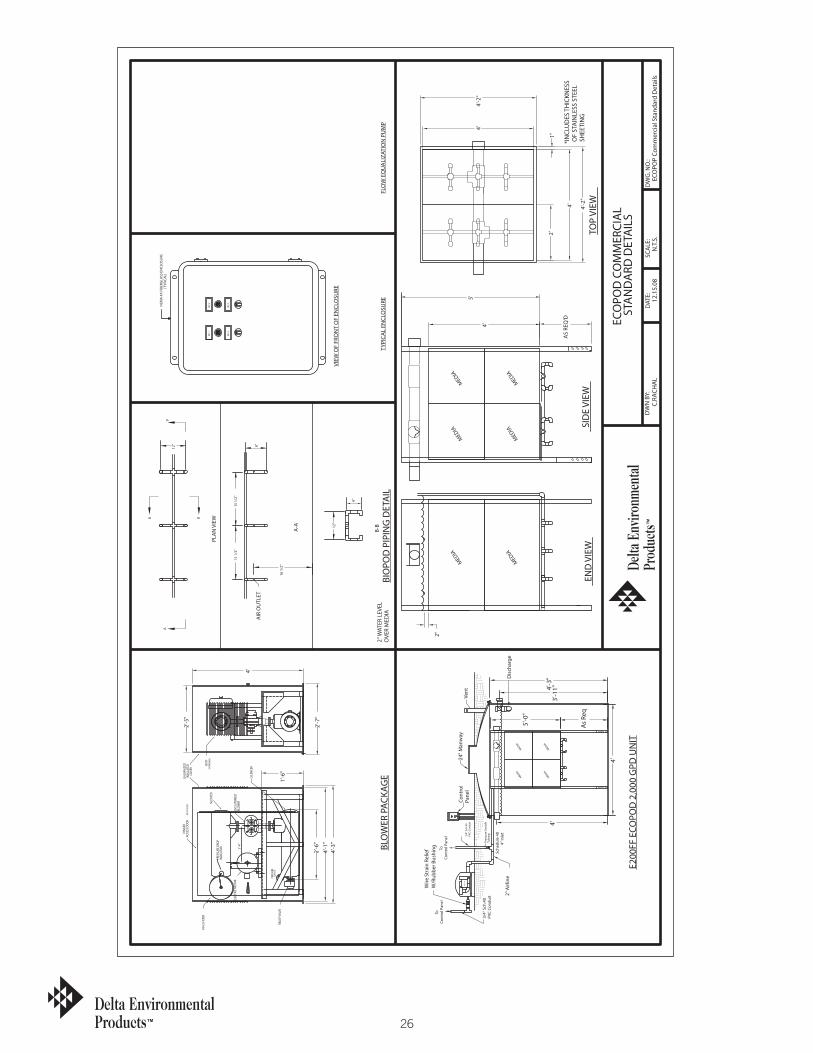
26
P. O
. BO
X 96
9 D
ENH
AM
SPR
ING
S, L
A 7
0727
DEL
TA E
NVI
RON
MEN
TAL
PRO
DU
CTS
ECO
POD
CO
MM
ERCI
AL
DW
N B
Y:C.
RACH
AL
STA
ND
ARD
DET
AIL
S
ECO
POP
Com
mer
cial
Sta
ndar
d D
etai
lsN
.T.S
.12
.15.
08D
ATE:
SCA
LE:
DW
G. N
O.:
*IN
CLU
DES
TH
ICKN
ESS
OF
STA
INLE
SS S
TEEL
SH
EETI
NG
TYPI
CAL
ENCL
OSU
REBI
OPO
D P
IPIN
G D
ETA
ILBL
OW
ER P
ACKA
GE
2" W
ATER
LEV
EL
OVE
R M
EDIA
END
VIE
WSI
DE
VIEW
TOP
VIEW
VIEW
OF
FRO
NT
OF
ENCL
OSU
RE
FLO
W E
QU
ALI
ZATI
ON
PU
MP
E200
FF E
COPO
D 2
,000
GPD
UN
IT
NP-
4
NP-
2
NP-
3
NP-
1
NEM
A 4
X FI
BERG
LASS
EN
CLO
SURE
(TYP
ICA
L)
1'-4
"
3/4"
Sch
.40
PVC
Cond
uit
ToCo
ntro
l Pan
el
2" A
irlin
e
3/4"
Sch
.40
PVC
Cond
uit
Wire
Str
ain
Relie
fW
/Rub
ber B
ushi
ngCo
ntro
l Pan
elTo
Tubi
ngPr
essu
re S
witc
h
COM
PRES
SOR
Dis
char
ge
Cont
rol
Pane
lVe
nt
Sche
dule
40
4" I
nlet
24" M
anw
ay
2"
4'
5'
4'
2'1"
4'-2
"
4'-2
"4'
4'-3
"
BLOW
ER
PRES
SURE
DRO
PIN
DICA
TOR
PRES
SURE
GAUG
E
1'-6
"
F64-
2 FI
LTER
SILE
NCER
2'-6
"
RELI
EF VA
LVE
2M SU
TORB
ILT
SILE
NCER
ELEC
TRIC
MOT
OR
GALV
ANIZ
EDIN
SULA
TED
COVE
RAC
CESS
DOO
R
VENT
(BOT
H EN
DS)
(BOT
H SI
DES)
HING
ED2'
-5"
4'-1
"2'
-7"
4'
AS
REQ
'D
MED
IAM
EDIA
MED
IA
As
Req
5'-0
"
MED
IAM
EDIA
MED
IAM
EDIA
4'
4'
4'-3
"3'
-11"
MED
IAM
EDIA
MED
IA
12"
6"
A-A
PLA
N V
IEW
16 1
/2"
AIR
OU
TLET
15 1
/2"
A
6"
15 1
/2"
A
B
12"
B
B-B
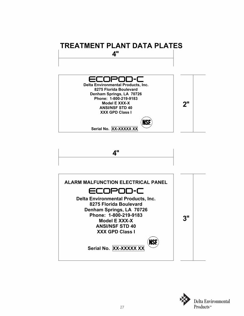
27
TREATMENT PLANT DATA PLATES
Delta Environmental Products, Inc.8275 Florida Boulevard
Denham Springs, LA 70726Phone: 1-800-219-9183
Model E XXX-XANSI/NSF STD 40XXX GPD Class I
Serial No. XX-XXXXX XX
2"
4"
ALARM MALFUNCTION ELECTRICAL PANEL
Delta Environmental Products, Inc.8275 Florida Boulevard
Denham Springs, LA 70726Phone: 1-800-219-9183
Model E XXX-XANSI/NSF STD 40XXX GPD Class I
Serial No. XX-XXXXX XX
3"
ECOPOD-C
ECOPOD-C
4"

K4479 05/09©2009 Delta Environmental Products