commission of the european communities nuclear science and
TRANSCRIPT

A1-s4e ISSN 1018-5593
Commission of the European Communities
nuclear science and technology
MANAGEMENT OF TRITIUM CONTAMINATED WASTES NATIONAL STRATEGIES AND PRACTICES
AT SOME EUROPEAN COUNTRIES, USA AND CANADA
Report
EUR 13592 EN
Blow-up from microfiche original


/
•
Commission of the European Communities
nuclear science and technology
MANAGEMENT OF TRITIUM CONTAMINATED WASTES
1992
:::NATIONAL STRATEGIES AND PRACTICES AT SOME EUROPEAN COUNTRIES,
USA AND CANADA
F. MANNONE '-
Commission of the European Communities Joint Research Centre
Institute for Safety Technology lspra Establishment 1-21020 lspra (VA)
FINAL REPORT
Directorate-General Science, Research and Development
Joint Research Centre

Published by the COMMISSION OF THE EUROPEAN COMMUNITIES
Directorate-General Telecommunications, Information Industries and Innovation
L-2920 LUXEMBOURG
LEGAL NOTICE
Neither the Commission of the European Communities nor any person acting on behalf of the Commission is responsible for the use which might be made of the following
information
Catalogue number: CD-NA-13592-EN-C
© ECSC - EEC - EAEC, Brussels - Luxembourg, 1992
•

III
ABSTRACT
The European Tritium Handling Experimental Laboratory (ETHEL) is the Commission of European Communities facility designed for handling multigram quantities of tritium for safety inherent R&D purposes. Tritium contaminated wastes in gaseous, liquid and solid forms will be generated in ETHEL during the experiments as well as during the maintenance operations. All such wastes must be adequately managed under the safest operating conditions to minimize the releases of tritium to the environment and the consequent radiological risks to workers and general population. This safety requirement can be met by carefully defining strategies and practices to be applied for the safe management of these wastes. To this end an adequate backgr01md information must be collected which is the intent of this report. Through an exhaustive literature survey current strategies and practices applied in Europe, USA and Canada for managing tritiated wastes from specific tritium handling laboratories and plant have been assessed. For some countries, where only tritium bearing wastes simultaneously contaminated with nuclear fission products are generated, the attention has been focused on the strategies and practices currently applied for managing fission wastes. Operational criteria for waste collection, sorting, classification, conditioning and packaging as well as acceptance criteria for their storage or disposal have been identified. Waste storage or disposal options already applied in various countries or still being investigated in terms of safety have also been considered. Even if the radwaste management strategy is submitted to a nearly continuing process of review, some general comments resulting from the assessment of the present waste management scenario are presented.


v
ACKNOWLEDGEMENTS
The author wishes to thank the indicated experts of Nuclear Research Centres, Laboratories, Plants and Projects involved in R&D activities and programmes dealing with tritium technology, namely:
- B. HIRCQ and P. PAILLARD of CEN Bruyeres le Chatel (CEA); - P. GIROUX of CEN Valduc (CEA); - G.B. BUTTERWORTH of Culham Laboratory, Abingdon, Oxon; - J.L. ANDERSON of TSTA (LANL) Los Alamos, NM.; - H.F. ANDERSON of EG&G Mound Plant, Miamisburg, Ohio; - M.L. ROGERS of EG&G Mound Applied Technologies, Miamisburg, Ohio; - A.B. MEIKLE and O.K. KVETON of CFFTP, Mississauga, Ontario; - W.T. SHMA YDA and J.P. KRASZNAI of Ontario Hydro, Toronto, Ontario;
for their kind cooperation in reviewing some sections of this report and/or providing valuable information and comments. Finally the valuable help of B.A. HUNT and P. ROCCO of JRC-Ispra in providing some interesting reports and review articles is also acknowledged.

VII
CONTENTS
ABSTRACT ACKNOWLEDGEMENTS
Page
III
v
1. INTRODUCTION .............................................................................................. 1
2. FRANCE ............................................................................................................ 2
3. FEDERAL REPUBLIC OF GERMANY......................................................... 16
4. UNITED KINGDOM ........................................................................................ 20
5. SWEDEN ............................................................................................................. 30
6. UNITED STATES .............................................................................................. 39
7. CANADA ........................................................................................................... 50
8. SUMMARY ........................................................................................................ 62
9. CONCLUSIONS ................................................................................................. 71
10. REFERENCES ................................................................................................... 77
APPENDICES ............................................................................................................. 81
APPENDIX I
APPENDIX II
Characteristics and Dose Rate Limits of Packages To Be Used for Deep Geological Disposal of Radioactive Wastes in FRG. ........................................................................................ 83
Features of Standard Waste Containers and Packages Currently Under Development in UK for the LLW and ILW Disposal Into a Deep Repository. .............................................................. 87
APPENDIX III : Characteristics and Dose Rate Limits of Packages To Be Used for the Shallow and Deep Geological Disposal of Radioactive Wastes in Sweden..................................................... 91
APPENDIX IV : Packaging Methods and Transport Containers Presently Available in the US for Tritium Shipping Purposes.................. 95
ABBREVIATIONS AND ACRONYMES ................................................................. 99
GLOSSARY ................................................................................................................ 1 03


:~. 1
1. INTRODUCTION
The European Tritium Handling Experimental Laboratory (ETHEL) located on the site of Ispra Joint Research Centre of the Commission of the European Communities (CEC), has been commissioned to experimentally develop various aspects related to the safety of tritium technology in fusion. However, since all experimental activities planned for the execution in ETHEL will by itselves generate tritiated wastes, current strategies and 'practices to be applied in ETHEL for the routine management of these wastes need to be defined.
To attain this target, an adequate background information is required. Alternative options concerning tritiated waste management which have so far been investigated or applied in many countries have recently been assessed ( 1 ).
The intent of this report is that of providing detailed information on how the problem of tritiated waste management has been solved especially in those countries where installations or laboratories are being specifically utilized for tritium handling purposes so that the management of tritiated waste arisings is a requirement to be met according to specific strategies, norms and practices.
Some additional information is also given in this context concerning the present strategies applied in some European countries for managing nuclear fission wastes. This is because the only tritium bearing wastes till now produced in these countries are those simultaneously contaminated with nuclear fission products and managed accordingly. Therefore a possible solution of the problem of the management of future fusion wastes which could be envisaged at present in this countries is that of adapting to such new waste forms the existing management strategies and practices till now applied for the current management of tritiated fission waste.

2
2. FRANCE
In France, beside the fuel reprocessing plants, other major sources of tritiated wastes are indeed the Tritium Extraction Facility at the LAUE-LANGEVIN Institute of Grenoble and the tritium research facilities at the nuclear centres of Valduc and Bruyeres le Chl\tel, both operated by the CEA-DAM (i.e. Direction des Applications Militaires of the french Atomic Energy Commission).
At Grenoble some hundred grams of tritium (-72 PBq) have been recovered from the heavy water of high flux reactors and other sources until 1986, i.e. during approximately sixteen years of plants operation (2). Significantly higher amounts of tritium have presumably been processed for military purposes at Valduc and Bruyeres le Chatel where a multiannual experience in handling and processing tritium have been reached. The CEN-Valduc started in 1965 its tritium handling experimental activities and is, since 1980, the only central storage deposit for all french tritiated wastes. A tritium experience of about twenty-five year has been reached at the CEN-Bruyeres le Chatel especially in the field of the basic DT gas processing as well as inherent routine operational and analytical support activities (3). Relying on this experience the Commission of the European Communities has assigned to this Centre the experimental development of some research activities within the framework of the European Fusion Technology and Safety Programme (3).
The various techniques and criteria applied for the management of tritium contaminated wastes produced at these Centres have been described by many papers presented at the Dijon Symposium in April 23-25, 1986 (4-13) and are here summarized.
2.1 Tritiated Waste Classification
The sorting and classification of french tritiated wastes are operations already initiated at source by each single waste producer. They are accomplished on the basis of their physical state (gaseous, liquid, solid), their nature (organic, inorganic, metallic, compressible, combustible, etc.) and their origin (gaseous streams from primary experimental circuits or secondary containment systems, solids and condensates from the treatment of these streams, process as well as structure components from equipment and containment systems, etc.).
Tritium contamination levels of gaseous and liquid wastes can be easily measured by sampling and counting techniques.
In the case of solid wastes such measurement techniques become complex and not sufficiently representative because of the non-homogeneous distribution of tritium in the waste material. Consequently the tritium contamination level of tritiated hardwares and miscellaneous solids is currently evaluated according to their origin, although only on a qualitative basis. To assist surface activity and outgassing rate measurements are normally applied.
It is worth noting that the processing of tritiated gaseous stream leads to the production of tritiated liquid condensates which are reprocessed for tritium recovery and recycle or wasted.
Depending on their origin tritiated soli.d wastes can be preliminarly subdivided into (4-6):
3
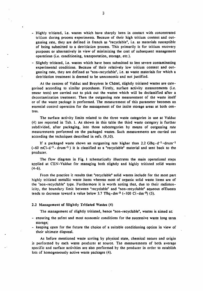
- Highly tritiated, i.e. wastes which have sharply been in contact with concentrated tritium during process experiments. Because of their high tritium content and outgassing rate, they are defined in french as "recyclable", i.e. as materials susceptible of being submitted to a detritiation process. This primarily is for tritium recovery purposes or alternatively in view of minimizing the cost of subsequent management operations (i.e. conditioning, transportation, storage, etc.).
- Slightly tritiated, i.e. wastes which have been submitted to less severe contaminating experimental conditions. Because of their relatively low tritium content and outgassing rate, they are defined as "non-recyclable", i.e. as waste materials for which a detritiation treatment is deemed to be uneconomic and not justified.
At the centres of Valduc and Bruyeres le CMtel, slightly tritiated wastes are categorised according to similar procedures. Firstly, surface activity measurements (i.e. smear tests) are carried out to pick out the wastes which will be declassified after a decontamination treatment. Then the outgassing rate measurement of the waste itself or of the waste package is performed. The measurement of this parameter becomes an essential control operation for the management of the insite storage areas at both centres.
The surface activity limits related to the three waste categories in use at Valduc (4) are reported in Tab. 1. As shown in this table the third waste category is further subdivided, after packaging, into three subcategories by means of outgassing rate measurements performed on the packaged wastes. Such measurements are carried out according the techniques described in refs. (9,10).
If a packaged waste shows an outgassing rate higher than 2.2 GBq. d-1 • drum-1
(-60 mCi·d-1 • drum-1) it is classified as a "recyclable" material and sent back to the producer.
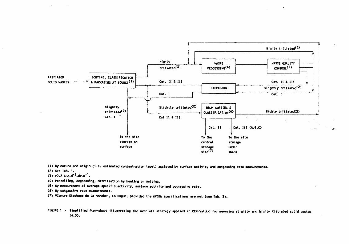
The flow diagram in Fig. 1 schematically illustrates the main operational steps applied at CEN-Valduc for managing both slightly and highly tritiated solid wastes (4-6).
From the practice it results that "recyclable" solid wastes include for the most part highly tritiated metallic waste items whereas most of organic solid waste items are of the "non-recyclable" type. Furthermore it is worth noting that, due to their radiotoxicity, the boundary limit between "recyclable" and "non-recyclable" aqueous effluents tends to decrease toward a value below 3.7 TBq ·dm-s (-100 Ci ·dm-3) (5).
2.2 Management of Slightly Tritiated Wastes (4)
The management of slightly tritiated, hence "non-recyclable", wastes is aimed at
- ensuring the safest and most economic conditions for the successive waste long term storage;
- keeping open for the future the choice of a suitable conditioning option in view of their ultimate disposal.
As before mentioned waste sorting by physical state, chemical nature and origin is performed by each waste producer at source. The measurements of both average specific and surface activities are also performed by the producer in order to establish lots of homogeneously active waste packages (4).

' •
TABLE 1 - Classification into categories applied at the Centre of Valduc for "non-recyclable" slightly tritiated solid wastes (4).
SURFACE ACTIVITY (A.cm-2) CAT.
kBq Ci
3.7x1o-3 <1> 10"4
<A< <A< 37x1o·3 10"3
II 37x1o·3 10-3 <A< <A< 1.85 5x1o·2
III >1.85
A >1 .85 >5x1o-2
B >1.85
c >1.85 >5x1o·2
GBq
<1.35x1o·3
1.35x1o·3 <A<
5.55x1o·2
5.55x1o·2 <A<
2.22(2)
Curies
<5x1o·5
5x10·5
<A< 1.5x1o·3
1.5x1o·3 <A<
6.0x1o·2
REMARKS
Structural waste materials with a low probability of having been in contact with tritium. They are stored at Valduc on a suitable site surface area and may be declassified in a short time.
Structural and component waste material slightly con· taminated by tritium. If their specific activity is <7.4 GBq•t·1 (<0.2 Ci• t-1) and the outgassing rate <5x1o·3x per day, they can be sent to a Central Storage Site.
Component waste materials having a tritium contamina· tion level superior to that of categories I & II. They are stored at Valduc inside different stores according to their outgassing rate (see Table 2).
(1) Solid wastes having a surface activity below this limit are considered as non-contaminated wastes. (2) Packaged wastes having an outgassing rate higher than this limit are deemed to be "recyclable" and sent back to the producer.
TRITIATED SOliD WASTES
SORTING, CLASSIFICATION & PACKAGING AT SOURCE(1)
Slightly tri ti ated<2> Cat. I ....
To the site storage on surface
\,. v
Highly WASTE tritiated<3> PROCESSIMG<4>
Cat. II & Ill
:r--1 PACKAGING
Cat. I
Slightly tritiated<Z>
Cat II & Ill
DRUM SORTING & ClASSIFICATION(6)
cat.
t To the central storage site<1>
II
·-·
cat. Ill
t To the site storage ~r
sheds
Highly tritiated<3>
WASTE QUALITY COHTROl(5)
1--
Cat. ll & III
Slightly tritiated<2>
Cat. t
Highly tritiated(3)
.
CA,B,C)
(1) By nature and origin Ci .e. estimated conta~~ination level) assisted by surface activity and outgassing rate ~~easurements. <2> See Tab. 1. (3) >2.2 Gaq.d·1.drum·1. (4) Parcelling, degreasing, detritiation by heating or melting. (5) By measurement of average specific activity, surface activity and outgassing rate. (6) By outgassing rate measurements. (7) "Centre Stockage de la Manche", La Hague, provided the ANORA specifications are met (see Tab. 3).
FIGURE 1 • Simplified flow·sheet illustrating the over·all strategy applied at CEN·Valduc for managing slightly and highly tritiated solid wastes (4,5).
-.
---

6
The measurements of tritium outgassing rate are performed both by the producer and the receiving service which is responsible for the management of such wastes.
Each drum is associated with a record on which information concerning the waste nature and origin as well as measurement data are reported.
The flow diagram in Fig. 2 illustrates the various handling operations applied at the CEN-Valduc for managing slightly tritiated gaseous, liquid and solid wastes.
2.3 Management of Highly Tritiated Wastes (5)
The management of highly tritiated (hence "recyclable") wastes is aimed at: - recovering and recycling an expensive radionuclide such as tritium; - ensuring the safest and most economic conditions for the waste managements opera-
tions at short and long terms; - achieving the knowledge needed in the field of tritiated waste management in view
of solving problems which will arise from the operation of future thermonuclear fusion reactors.
Four waste processing procedures are applied at the Centres of Valduc and Bruyeres le Chatel (5-8) for the management of highly tritiated gaseous, liquid and solid wastes. As summarized in Fig. 3 they entail:
I. The diffusion of non-oxygenated gaseous effluents from experimental tritium circuits (cat. I) through a membrane of Pd-Ag alloy at 650 K (-380°C). The diffusion is carried out after having adsorbed the HTO vapor by passing the gaseous stream on a molecular sieve (MS) bed. Tritiated hydrogen, tritium and hydrogen can be then separated from other gaseous components (CH8T, C02) which do not diffuse. Tritium traces in the residual not-diffused gaseous stream are then catalytically oxidized to HTO after air addition (7) (see Fig. 3).
II. The oxidation of tritiated gaseous effluents containing air (cat. II). They are usually originated by maintenance operation or accidental incoming of air into experimental tritium circuits (7) as well as by tritium contamination of glove-box ventilation atmosphere (8). After the catalytic oxidation of HT, the HTO vapor is adsorbed on a MS bed and then periodically desorbed and condensated for being recycled to the aqueous effluent treatment (see Fig. 3).
III. The reduction of tritiated water for recycling the recovered tritium. Depending on its tritium concentration, tritiated water may require to be previously submitted to an isotopic enrichment process (5) (see Fig. 3). The HTO reduction to HT may be accomplished by electrolysis or alternatively by chemical reaction in contact with metallic uranium at 775 K (-500°C). The resulting tritiated gaseous stream is then recycled to the gaseous effluent treatment, while the residual depleted water is handled as a slightly tritiated aqueous effluent (5, 7).
IV. The detritiation of solid waste materials. The management system employed at Valduc (5,6) for detritiating hard waste materials includes, along with installations for waste sorting and cutting two units for thermal treatments. The tatters are based on heating under depressure and inert gas stream or melting under vacuum of metallic wastes such as stainless steel, alloys, brass, nobel metal items, etc.

GASEOUS EFFLUENTS(1) !1.85 MBq·m·3 (!0.5 MCi·m·3)
LIQUID WASTES(2) <3. 7 TBq·dm·3
(102 Ci·dm-3)
SOLID WASTES(3) <2.2 G8q·d· 1·drum·1
(-60 mCi·d· 1• drum·1)
HT·CATALYTIC OXIDATION(4)
HTO HTO ADSORPTION HTO ON M.s.(7) TRACES
HTO DESORPTION & CONDENSATION
.---condensates j
FIXATION ON Cat. I
ABSORBERs(5) - Solid waste Drums coqx>sites
PACKAGING(S) l I Cat II
MONITORING
Cat. I
Cat. II
DRUM SORTING & 1----
CLASSIFICATION(9) Cat. IliA
& Ill Drums Cat. 1118, IIIC
WASTE SORTING & Cat. I , II & Ill
CLASSIFICATION(6) 1-- Solid wastes
>2.2 GBq·d·1·drum·1
(-60 mCi·d·1·drum·1)
DISCHARGE TO STACK(10)
SURFACE STORAGE ON THE SITE
TRANSPORTATION TO A CENTRAL
STORAGE SITE< 11 >
NON-VENTILATED STORAGE< 12>
VENTILATED STORAGE< 12>
HIGHLY TRITIATED SOLID WASTE
PROCESSING< 13>
FIGURE 2 · Schematic flow-diagram of handling operations applied at CEN·Valduc for managing slightly tritiated gaseous, liquid and solid wastes (4).

FIGURE 2 · (Continued).
(1) Dry air or inert ventilation atmosphere from glove-boxes. The initial tritium activity in the atmosphere depends on the kind of G·B handling operation.
(2) Tritiated waters. No tritiated oils. Other tritiated organics are collected and burnt with HTO separation from combustion gases. (3) Organic, inorganic (e.g. concrete debris) and metallic wastes. (4) ~ithin 420 to 700 K <-150° to 430°C). (5) Molecular sieves for aqueous effluents, vermiculite for organics. (6) By nature and origin (i.e. contamination history) assisted by surface activity measurements. (7) MS adsorption at room temperature, desorption at 520 K <-250°C). (8) ~ith and without volume reduction. (9) By outgassing rate measurements. (10) ~ithin the allowed discharge limit. ( 11) Centre de Stockage de La Manche. (12) See Tab. 2. (13) See Fig. 3.

GASEOUS EFFLUENTS - Cat. I <1)
3·30 PBq • m· 3
<-80·800 kCi • m·3>
- Cat. 11<2> 0.1·10 PBq ·m·3
<-3.0·300 kCi • m·3)
AQUEOUS EFFLUENTS(3) >3.7 TBq·an·3
c-1o2 ci ·an·3,
SOLID WASTE(4) >2.2 GBq•d-1•drun (>60 mCi·d·1·drum>
l HT HTO CH3T
- COz
Air HT HTO CH3T toz
HT traces Hz, HT traces< 14> To recycle T traces r------
r Tz, H
CH3T, COz
---- DIFFUSION ON r--!!!. ISOTOPIC - - - - -- -- l I -
PD/AG MEMBR.< 13> SEPARATION(15)
I I
'-- I HTO ADSORPTION -~
HT·CATALYTIC ON M.S. (8)
h Gaseous DISCHARGE
r _, MONITORING l OXIDATION(5) HTO ~ TO STACK(16) .- COz HTO DESORPTION residue< 12> \..I I
& CONDENSATION
T/IH<10" 2 Condensates
T/I H>10" 2
Tritiated gases
f SLIGHTLY
'\ HTO ISOTOPIC HTO Slightly tritiated water TRITIATED ~
I ENRICHMENT(6) REDUCTION(9) LIQUID WASTE SOLIDIFICATION< 17>
uo2 bed (T·traces) Tritiated gases
r SLIGHTLY TRITIATED
SIZE THERMAL QUALITY Slightly tritiated SOLID WASTE REDUCTION(7) TREATMENT(10) CONTROL< 11 > sol ids CONDITIONING< 17>
j >2.2 GBq ·d·1·drun + FIGURE 3 · Schematic flow·sheet of process treatments applied at CEN·Valduc and Bruyeres le Chatel for managing highly tritiated gaseous, liquid and
solid wastes (5·8).

FIGURE 3 · (Continued).
(1) Cat. I, non-oxygenated: HT, HTO, Argon, CH3T, co2 from centralized vacuum stations. (2) Cat. II, oxygenated: air, HT, HTO, Argon, CH3T, co2 from centralized vacuum stations. (3) Tritiated water condensates. (4) Metals, glasses, molecular sieves, catalysts, etc., into 200 ~drums. (5) Oxidation of tritiated hydrogen and methane within 420 to 700 K (-150° to 430°C) (8). (6) By isotopic exchange in liquid phase. (7) By dismantling or cutting. (8) HTO adsorption on molecular sieves at room temperature, desorption at 520 K <-250°C). (9) By electrolysis or alternatively by chemical reaction in contact with metallic uranium at 775 K <-500°C). (10) Heating under depressure in argon stream for molecular sieves, metallic valves, glasses and catalysts. Melting under vacuum for metals and
degassing inside a oven for organic materials. (11) By measurement of average specific activity, surface activity and outgassing rate. (12) Residual gas (C02, HT traces) having an activity <0.1 TBq ·m·3 (-3 Ci • m·3) and a reduced volume. (13) Permeation at 650 K <-380°C). Resulting gaseous fractions: product (HT) = 5·50 PBq·m·3; residue (HT traces, CH3T, C02) <0.5 PBq·m· 3• (14) To detritiation by HT oxidation (HTO) or compression and storage. (15) By gas-solid chromatography on Pd/Alumine columns within a temperature range of 230 to 270 K (·43° to ·3°C).
Initial feed T from SX to SOX; · Final head product : T > 99X
: H < 0.2X (16) Within the allowed discharge limit. (17) See Fig. 2.
....... 0

11
Furthermore a degassing oven is applied for detritiating organic waste materials suCh as organic components of valves, etc. Tritiated gases which are liberated from such wastes are sent to the gaseous effluent treatment (see Fig. 3).
As pointed out in ref. (6) after such pretreatments detritiated metallic wastes normally exhibit improved safety characteristics, namely:
- A significantly reduced tritium radioactivity on the waste surface and accordingly a reduced tritium outgassing, so that the handling of these waste forms become less hazardous. The best evidence of this advantage is indeed achieved in the case of melting of tritiated metallic wastes whereby, beside tritium contamination and outgassing, also the overall dimensions and specific surface of the resulting waste form are significantly reduced.
- A better distribution of residual tritium contamination (i.e. homogeneity) in the bulk of the ultimate waste form, so that more representative samplings are allowed for measurement purposes. However, this advantage is specific only to waste melting treatment.
2.4 Long Term Surface Storag~ of Tritiated Wastes at CEN-Valduc (4)
As shown in Fig. 3 slightly tritiated solid wastes after drummining and categorization by outgassing rate measurements are stored in adequate surface facilities.
Since I 980 various surface storage facilities have been made available at Valduc for the long term storage of tritiated waste packages produced by the Centre itself as well as by other french tritium handling sites (e.g. Centre of Bruyeres le CMtel).
The cat. I wastes are stored pending the declassification (i.e. the lowering of the surface activity to less than 3.7xlo-s kBq .cm-2) on a suitable surface area of the site.
As shown in Tab. 2, depending on the measured value of outgassing rate different types of surface storage facilities are utilized for the long term storage of drummed "non-recyclable" solid wastes (4).
2.5 Shallow Land Burial of Tritiated Wastes at CSM, La Hague
Cat. II tritiated solid wastes with a surface activity lower than 1.85 kBq ·em -2 are usually sent. for shallow burial to the "Centre de Stockage de La Manche" (CSM) at La Hague. This disposal option is however strongly limited in France by the specifications (i.e. the activity limits and the preparation guidelines) defined by ANORA, the french National Agency which is responsible of the management of long term waste storage centres. This is true for La Hague as well as for the second french site at Soulaine (Department de L'Aube). ·
According to the ANORA specifications, only two types of tritiated wastes can be accepted at La Hague for disposal (see Tab. 3): - miscellaneous soft and hard wastes with a tritium specific activity equal or below
7.4 GBq ·t-1 (0.2 Ci ·t-1); - hard wastes with a tritium specific activity within 7.4-74.0 GBq ·t-1 (0.2-2.0 "Ci·c1).

TABLE 2 · Characteristics of the various storage fa~ilities employed at CEN·Valduc for long term storage of tritiated waste drums (4).
TRITIATED WASTE DRUMS BUILDINGS VENTILATION SYSTEMS
Waste OUtgassing rate Bld. Surface Storage capacity Flow Exchange Stack category (A d" 1 drum) type (m2) (No. drum store-1) rate rate height
(No.) <ml h" 1> (No. h" 1> (m)
GBq Curies Maximum Stored
1.50x1o·4 4.0x10· 6 Hangar 1590(2) No ventilation,
IIIA< 1> <A< <A< (058) 400 2500 2400(3) no stack 1.35x1o·3 5.0x1o·5
1.35x1o·3 5.0x1o· 5 Hangar 2o3o<2>
IIIB< 1> <A< <A< (055) 1200 5000 28oo<3> 4x32000 15 none
5.55x1o· 2 1.5x1o·3
--'
5.55x1o· 2 1.5x1o·3 N Store
IIIC( 1) <A< <A< (026) 250 600 395< 2> 6000 20 20 2.22 6.0x1o·2
(1) Tritium surface activity >1.85 kBq cm·2 (5x1o·2 microCi cm" 2>. (2) Till 1986. (3) Till 1991.

TABLE 3 . Tritium activity limits fixed by ~NORA specifications for the acceptance of tritiated waste packages at the "Centre de Stockage de la
Manche" (La Hague, France).
WASTE PACKAGE IDENTIFICATION TRITIUM ACCEPTANCE LIMITS PER PACKAGES
T·SPECIFJC TYPE OF USEFUL TYPE OF DENSITY MAXIMUM MAXIMUM OUTGASSING RATE(4)
ACTIVITY PACKAGE VOLUME INCORP. (t • m·3) SPECIFIC ACTIVITY CGBq ·t-1)(Ci ·t-1) cml> MATRIX (% d"1) (kBq•d" 1) (microCi • d·1)
(GBq • t·1) (Ci•t" 1>
~7.4 ~0.2 drum<1> 0.2 none -1.5 7.4 0.2 Sx1o·3 111 3.0
7.4 0.2 to to drum<2> 0.2 cement -2.0 74 2.0 Sx1o·4 148 4.0
74.0 2.0
7.4 0.2 concrete to to shell <3> 1.0 cement -2.0 74 2.0 Sx1o·4 740 20
74.0 2.0
(1) Standard metal drums.
(2) Steel or epoxy resin (reinforced by glass fibers) drums lined with a 2 em thick layer of epoxy resin.
(3) Reinforced concrete shell (C1 type) internally lined with a 2·3 em thick layer of epoxy resin.
(4) At t = 20° ! 5°C. (5) Fractional leach rate by permanent immersion in water (at a pH within 7·8 and a salt content of 0.5 g·l-1).
MAX.LEACH RATE(S) REF.
ca·1)
9
5x1o·2 11
Sx1o·2 11
...... w

14
The first ones are accepted under any waste form they are without encapsulation requirement, but provided tritium outgassing rate at 20 ± soc do not exceed the value of 5xlo-s% per day. Conversely the second ones must be encapsulated by cement grout and. protected by an epoxy resin barrier (11) so that tritium outgassing rate of the waste composite at 20±5°C do not exceed the value of 5xl0-•01o per day. The above outgassing limits are referred to a maximum specific activity of 7.4 GBq • t-1 for the 1•t type and 74 GBq .t-1 for the 2nd type of wastes (1 I).
Package types that can be used for waste disposal at La Hague are: - Standard metal drums for the first waste type(< 7.4 GBQ·t-1). - Steel or reinforced epoxy resin drums as well as reinforced concrete shells, inter-
nally lined with an epoxy resin layer for the second waste type (7.4 GBq·t-1 < A < 74 GB·t-1).
The disposal of such wastes can be implemented by using two disposal structures, i.e. tumuli or reinforced concrete monoliths, depending on the package type and its surface dose rate (28).
Disposal in tumuli is carried out on drained concrete platforms in order to keep the packages isolated from the direct contact with the soil. Piled-up slightly irradiating concrete shells are employed to create the structural frame of each tumulus. Low surface activity drums are stacked inside this frame. When the stacking has been completed a backfilling material is poured into voids between packages to guarantee the stability of the structure. The disposal area is then protected against rain water by a thick layer of impermeable clay and then covered by farming soil.
Highly irradiating packages are disposed in trenches lined with steel reinforced concrete. They are stacked in successive layers and concrete grout is then poured to fill the voids between packages. Reinforcing steel is added to the last concrete layer to complete the concrete monolith that also provide the base necessary for a tumulus.
Both these disposal structures are aimed to protect the packages against external interferences and to minimize the consequences deriving from abnormal situations. This is provided by a set of barriers such as earth, gravel and clay of tumuli, package walls and encapsulation matrix in the waste packages.
The structures are earthquake resistant and inaccessible to rainfall and underground waters. To check their tightness to water, two separated monitoring networks, accessible by inspection pits, are placed respectively at the bases of monoliths and tumuli (35).
2.6 Alternative Options for Disposing of Fusion Wastes
As reported in ref. (12) the last campaign of waste sea dumping was organized in 1981 by NEA (OECD) for Netherlands, Belgium and Switzerland under the surveillance of a french observer designed by the NEA as its representative. After this campaign a stop of any such operations was decided in 1983 by the majority of countries for political and social reasons. This was maily because of strong pressions of some ecologist groups representing a part of the public opinion and supported by their national Governments. Therefore, taking account of the worse nowday situation as to the public acceptance of the risks associated with the nuclear energy, the restart of sea dumping operations is to be excluded at least for the near future.
15
Apart from sea dumping, two alternative options are being taken into consideration in France (13) such as the deep geological and the under sea-bed disposal. However there are some constraints to make such options practicable in a reasonably short time.
At first a considerable long time is required to identify, investigate and qualify geological sites which are the most suitable and safe candidates for waste repository purposes. Secondly very important investements and operational costs are involved by both such options. Consequently their application will be economically justified, only when a quantitatively important production of tritiated wastes can reasonably be expected.
Another rather critical point is the degree of public acceptance. Its importance is well pointed out by the increasing difficulties encountered by ANORA in developing a fission waste management strategy based on the waste disposal in a deep geological repository. To give an example, test drillings have been initiated by ANORA in December 1989 at four candidate underground sites for the construction of a so-called "in situ verification laboratory" with the aim of studying conditions for emplacing high level and alpha-bearing wastes. However less than three months later ANORA was forced to halt test drilling at all sites for "at least" one year. This decision was taken by the French Government because of the emotional protests of groups representing the population living in the area of the candidate underground sites (14).

16
3. FEDERAL REPUBLIC OF GERMANY
All tritiated wastes till now generated in the FRG were always contaminated with other nuclear fission products so that their management has been considered in the more general context of fission wastes, classified into heat-generating and non-heat or negligible heat generating wastes.
No shallow land burial being foreseen in the FRG, three deep geological repositories are presently considered for disposing of radioactive wastes ( 15, 16), namely: - The KONRAD repository, a closed-down iron ore mine, situated near Braunschweig
(Lower Saxony) in the Peine-Salzailter area, at a depth of 1000-1200 m. It is de-, signed for all types of non-heat generating radioactive wastes. The GORLEBEN repository situated about 300 km north-east of Braunschweig in a saltdome. The site is under investigation to check the suitability of the saltdome for the disposal of all types of radioactive wastes including heat generating wastes from reprocessing and spent fuel elements. The MORSLEBEN repository, a salt mine situated in the new (ex-DDR) Federal State of Sachsen-Anhalt, operated since 1981 as a repository for low and intermediate radioactive wastes with low alpha-emitter concentrations.
The Konrad mine is the first german repository on a commercial scale. PTB has been since November 1989 the Federal Government Agency designed by the Atomic Energy Act to carry out final waste disposal. It was consequently the legal responsible for the construction and operation of repositories for radwastes disposal ( 15). Following the Federal Government decision of October 1989 (16,18) a new body, i.e. the Federal Office for Radiation Protection (BfS) is now the responsible for the establishment and operation of federal installations for long-term storage and disposal of radwastes, including since October 1990 the Morsleben repository. Being the authorized applicant, formerly PTB and now BfS has to demonstrate the safety of a repository in the operational and post-closure phase. This objective is usually achievable by a safety assessment of the site including the geology and hydrogeology, the technical design of the repository including its anticipate modes of operation under normal and accidental conditions as well as the waste packages usable for disposal in it (16). On the basis of the results of such an assessment, specific waste acceptance requirements may be derived. These requirements have to be met by conditioners wishing to dispose of their radwaste and will provide guidance for waste conditioning procedures (15,16,17).
After the site-specific assessment had demonstrated the safety of the Konrad mine as a repository for radwaste with a negligible heat generation, PTB has started in 1982 the licencing procedure for the Konrad repository. Revised and complete licencing documents have thus been submitted to the responsible authority in 1986. Although the finalization of the procedure was expected by the end of 1989 (I 5), the licencing is still pending ( 16).
Specific requirements for waste acceptance in the Konrad repository (i.e. waste forms, packages features, activity limitations, packaging and transportation procedures, etc.) have been derived from the safety analysis of the Konrad mine (16). However, as the Konrad licencing is still pending the w~ste acceptance requirements are referred to as still preliminary (19,20).
General features and surface dose limits of waste packages (see Tab. 1 of Appendix I) usable for disposal in the Konrad repository as well as maximum permissible
17
annual inventory per nuclide or nuclide group have been established. Allowable individual nuclide activities per package have also been roughly derived (17 ,32).
The heat generation by radioactive decay will limit the total beta-gamma activity to 1.8-30 TBq (-50-800 Ci) per package, depending on the type of package usable for waste disposal in Konrad.
As to tritium activity restrictions in tritiated metallic wastes a maximum total tritium activity of 4.7 PBq·a-1 (-127 kCi·a-1) and 9.6 PBq·a-1 (256 kCi·a-1) will be accepted as the annual disposal limit for the Konrad repository using waste packages respectively without and with a specified package tightness ( 17). A rough estimation of tritium restrictions per package gives approximately an activity limit of 0.47 TBq (-12 Ci) and 0.96 TBq (-25 Ci) per package without and with specified tightness respectively.
The second german waste repository has been planned at Gorleben in a saltdome that would be suitable especially for disposing of high level heat-generating and longlived wastes. Such wastes will be placed in boreholes, 300-600 m deep, all other waste types in mined rooms (tunnels).
Above-ground and underground explorations for investigating the site-specific geology, hydrogeology and hydrology have been undertaken at the Gorleben site over an area of approximately 30 km2 (15, 17 ,32). The now completed above-ground investigations confirms this salt dome is suitable for radwaste disposal (16). Underground explorations, began with shaft sinking in 1984, will supply further data to complete the final site-specific assessment of the salt dome envisaged for the end of the 1990s (16). The results of these investigations will form the scientific basis for the Gorleben licencing procedure.
One has to point out that the Gorleben preliminary waste acceptance requirements will possibly be derived from the final safety assessment of the site, hence only after the end of the 1990s. Nevertheless since radwastes with a negligible heat generation will be disposed of in tunnels using an emplacement technique similar to that envisaged in the Konrad tunnels, the adoption as a guideline of the Konrad preliminary waste acceptance requirements is a possible option (21 ). This appears reasonable even if the identity of the two set of requirements is not expected to be complete, due to the differences in technical designs of the two repositories.
Still preliminary information is available on the characteristics of waste packages usable for disposal into the future Gorleben repository. The standardization of cylindrical packages and containers for radwaste and spent fuel elements (21) was done jointly by the waste procedures and the PTB, mainly on the basis of the existing waste package standardization for the Konrad repository. As indicated in Appendix I, Tab. 2, eight types of packages are envisaged for the disposal of heat generating wastes in the future Gorleben repository. Of the fourteen packages envisaged for negligible heat generating wastes, the first twelve are identical to those intended for disposal of non-heat generating wastes in the planned Konrad repository (see Appendix I, Tab. 1).
Due to the higher weight handling capacity in Gorleben, hence to the more shielding usable for packages, gamma activity restrictions for dose rate reasons appear less stringent than for Konrad. On the other hand a maximum surface temperature of

18
100° and 200oc per package disposable respectively in Gorleben tunnels and boreholes has been fixed. This will allow to contain a much higher beta-gamma activity in each package corresponding to several kW per package (17).
Tritium activity restrictions for acceptance of tritiated wastes in the future Gorleben repository will deal with the annual outgassing rate per package which will be limited to 0.11 GBq .a-1 (-3 mCi .a-1) for disposal in tunnels and 1.85 GBq. a-1
(-5 mCi. a-1) for disposal in boreholes (17). As pointed out in ref. (32) by comparing these values with the annual outgassing limit fixed by ANORA for acceptance of tritiated waste packages at french Central Storage Sites, i.e. -0.14 GBq ·t-1• a-1
(-4 mCi-t-1.a-1) it results that the disposal in tu.nnels of packages containing approximately 1 t of detritiated fusion steel· wastes per package would be a possible option. However it is worth noting that the restriction concerning the inventory of tritium per package is still unknown (17).
As to tritiated liquid wastes, which usually arise in fairly large amount from spent fuel reprocessing operations, specific investigations have been undertaken in the FRG (22,32) to study their separate disposal by the deep-well injection. This option would entail the injection of the liquid waste through a deep borehole situated into an appropriate receiving geological formation at a depth of 1000 m or more. Some specific requirements of the receiving stratum are to be met such as porosity and absence of vertical faults. Another important requirement is the presence at the upper and lower boundaries of other strata whose thickness as well as integrity and impermeability are adequate for isolating the receiving formation (22). Owing to the uncertainties existing in connection with the licencing of such a disposal option, it has been planned to immobilise tritiated water arising from fuel reprocessing by cement hydration and to package the solidified water for in situ storage. It has been found that the eventual emplacement of tritiated concrete waste packages in the Konrad repository along with all other tritiated wastes which have been designed for disposal in it, would be possible. The annual limit of disposable tritium in activity fixed for such a repository would thus result nearly completely exhausted.
As to the Morsleben repository the German Federal Minister for the Environment has decided in March 1991 to order the temporary stop in this salt mine of the operations for the ultimate disposal of low and intermediate radwastes. This was decided even if the same order was already delivered by the Court of Justice of the Magdeburg. Both the decisions are based on the fact that since October 1989 the responsibility for the operation of federal installation for long term disposal of radwaste is assigned to the German Federal Office for Radiation Protection (BfS).
The Minister was also convinced that the long-term safety of the Morsleben repository needs to be further demonstrated by the assessment of the geotechnic characteristics of the site. It is anticipated that the results of this study will not be available before two or three years. Consequently the stop of this repository is likely to become a critical problem for the new (ex-DDR) "Hinder" because of the scarcity of interim storage sites.
Since many years R&D activities on tritium have been carried out in the FRG at the Nuclear Research Centre of Karlsruhe (KfK) within the framework of nuclear fuel reprocessing and radioecology (23).

19
Due to the participation of KfK to the European Fusion Technology Programme these activities have been greatly expanded. The prominent target was that of providing technical means enabling experiments with tritium quantities typically representative of future fusion devices. Thus it has been decided to implement a tritium laboratory (TLK) in the KfK (23).
The future experimental work in TLK will mainly be concentrated on the development of advanced processes for plasma-exhaust fuel clean-up, tritium extraction from metal breeder materials as well as tritium removal from gaseous waste streams by catalysts and getters. The final goal is the development of fuel cycle components and systems for NET /ITER (23,24).
In the first phase of basic experiments, tritium inventory will be limited to 10 grams of tritium while in a second phase development work it will be pushed up to a technical or semitechnical scale with an inventory of 200 grams.
The laboratory building whose construction started in 1986, as well as the installation of the components for the service systems, has been ultimated (24). Meanwhile the detailed engineering planning of most of the tritium process systems has been completed and orders are placed with industry. The projected date for the start of "cold" commissioning is mid 1991 while "hot" commissioning is envisaged to start six months later.
As far as the problem of tritiated waste management is concerned, no specific tritiated waste conditioning operations have up to now been established at TLK.

20
4. UNITED KINGDOM
4.1 Wastes from Operation of Nuclear Power Stations and Fuel Reprocessing Plants
Also in UK no specific management strategies and procedures have been till now foreseen for tritium contaminated wastes other than those currently applied for low level (LL W) and intermediate level wastes (ILW) generated by nuclear power stations (CEGB) and fuel reprocessing plants (BNFL).
The following categorisation proposed by the Radioactive Waste Management Advisory Committee is currently used in UK (25,26):
a) Low Level Wastes (LLW) i.e. wastes containing activities higher than 0.4 MBq. t-1 (-I 0 microCi • t-1) but in which the limits of 4 GBq. t-1 (-0.1 Ci. t-1) for alpha activity and 12 GBq. t-1 (-0.32 Ci. t-1) for beta-gamma activity are not exceeded.
b) Intermediate Level Wastes ( /LW) i.e. wastes containing activities exceeding the above LL W alpha and beta-gamma activity limits but which can not be qualified as HLW.
c) High Level ( HLW) or Heat Generating Wastes ( HGW) i.e. wastes in which the heat generation rate may increase so significantly, due to the radioactivity, that this parameter has to be taken into account in designing their storage or disposal facilities.
It must be noted that in the UK, solid wastes with activity below 0.4 MBq • t-1
(I 0 microCi • t-1) are defined as Very Low Level Wastes (VLL W) and are exempt from the requirements for authorisation prior to disposal as radioactive wastes.
The above categorisation refers to a waste encapsulated for disposal without including any overpack needed for shielding. The heat generating waste category is not presently being considered for disposal in a deep repository and does not arise in the decommissioning of nuclear facilities.
The LL W and IL W conditioning entails process operations aimed at converting a waste into a form suitable for transportation and storage or disposal. These processes may include the conversion of the waste to another form, its confinement in containers and then its additional packaging.
Compactable and combustible wastes are generally reduced in volume by mechanical compaction and/or incineration. In many cases the compaction can be performed with the material inside the transport container. The incineration produces concentrated waste ashes which needs further conditioning by incorporation in solidifying matrices.
The conditioning of non-combustibile or non-compactable waste materials requires in most case their reduction in smaller pieces to attain a greatest and more economical utilization of the standard package volume. The size reduction will also facilitate the waste encapsulation, if appropriate, into the packaging container with a suitable encapsulating medium.
Liquid wastes usually consist of large volumes of dilute solutions containing dissolved or particulate contaminants. Such wastes are normally processed to separate the

21
radioactive nucleides from the liquid phase by techniques of ion-exchange, membrane separation, chemical treatment, filtration and evaporation. The purified liquid may result sufficiently decontaminated to allow its discharge to the environment, whilst the encapsulation of the solid residues is usually carried out before their disposal.
Since 1959 most LL W arising from the nuclear industry have currently been disposed of by shallow land burial in trenches at the BNFL's Drigg site, located in Cumbria, about 6 km south-east of Sellafield. Even if the majority of the wastes comes from Sellafield, other users of radioactive materials also use Drigg on a commercial basis. Dounreay in Scotland is another site where the shallow land burial of LL W takes place. Furthermore, untill the moratorium on sea disposal introduced in 1983, some LLW and ILW have also been disposed of by sea dumping in the northeast Atlantic Ocean (25).
Drigg has always been operated by BNFL itself. Nevertheless, as announced by the UK Government in 1982, the responsability of the planning development and operation of future new disposal facilities and services for LL W and IL W has become a concern of the Nuclear Industry Radwaste Executive (NIREX).
NIREX was set up with an agreement between the Government and the main UK waste producers (i.e. UKAEA, BNFL, CEGB and SSGB). In 1985 it was incorporated as UK NIREX Limited.
At present NIREX is not at all concerned with research on deep land disposal of heat generating wastes (HLW). This is because in 1981 it was announced by the Secre-:tary of State for the Environment that research on the HL W land disposal option would have to be shelved in favour of a review of the applicability to the UK of the findings from such a research in other countries. On the contrary research concerning ocean disposal options would have to continue (25).
HL W have consequently been stored at Sellafield pending the incorporation into glass blocks i.e. the starting of the Sellafield new waste vitrification plant. Then, before disposal, an interim storage of fifty years is envisaged for such waste composites (25).
TABLE 4 • Radioactive waste treatment plants planned for Sellafield (25).
PLANT
Waste Vitrification Plant
Encapsulation Plants CEP1, EP2)
Enhanced Actinide Removal Plant and associated Waste Packing Encapsulation Plant
waste Treatment Complex
FUNCTION
HLW vitrification
ILW immobilization in concrete
Liquid effluent treatment by floc precipitation and ultrafiltration
Plutonium contaminated mate· rial treatment and packaging
OPERATIONAL DATE
1990
1990 (EPI) 1992 CEP2)
1992
Early 1990s

22
Conversely the UK strategy for the managements of LLW and ILW continually evolves, due to a continuing process of review to which is currently submitted.
Accepting a recommendation from NIREX, the Government decided in May 1987 that instead of a new separate facility for the future near surface disposal of LL W, a single deep facility for disposing of both LLW and ILW should be developed. Consequently the initial programme of site investigation at four shallow disposal sites was halted. NIREX work was therefore reoriented towards the identification of routes for deep disposal of both radwaste types. Three disposal options were defined and investigated (25) by NIREX such as: - deep burial on land, e.g. in mined tunnels; - disposal under sea-bed, e.g. in tunnels beneath the sea-bed with access from the
shore; - disposal into sea-bed with access from an offshore structure.
Technical geological assessment studies on such options were undertaken and the identification of suitable repository sites was planned for 1989. By considering at first those sites where there was a measure of support for nuclear activities in the local community, NIREX decided in 1989 to limit, as a first step, site investigations to two locations, namely Dounreay in Caithness and Sellafield in Cumbria. Anyhow NIREX has not excluded the possibility of investigating other locations at a later stage or utilizing off -shore options.
A time period of about 18 months was planned by NIREX to carry out detailed geophysical investigations of the two potential sites. Beside the results of these studies the public acceptability as well as transport considerations and environmental factors, will also be taken into account by NIREX in coming forward with a proposal. At this stage a decision has to be made on whether either or both sites is suitable for the construction of a waste disposal centre. The final choice was foreseen to be made by the Government after a full public debate. Assuming permission is granted for construction, which could start in 1996. the operational availability of the repository has tentatively been anticipated around the year 2005.
At Dounreay the depth envisaged for the repository would be about 500 m below the ground level, while that at Sellafield could be somewhat deeper. Wastes should be placed by remotely operated overhead travelling cranes,while stacks of packages should be stabilized by a cement based backfilling.
As reported in ref. (32) the CEGB has reviewed waste management practices applied at all its nuclear power stations. In addition to waste incineration or compaction, some potential for further volume reduction has been found for LLW.
Even if rather low amounts of ILW (i.e. sludges, resin, fuel debris) from CEGB stations have been till now conditioned, immobilisation plant or increased storage capacity are foreseen for their future management. In the mean time a range of standard waste packages have been developed and qualified by NIREX in collaboration with UK waste producers for containment and transport of solid LL W and IL W immobilised in concrete. A summary description of these packages is given in Appendix II.
Although in future Drigg disposal site will be reserved only for L.L W arising at Sellafield, the authorization for disposal of radioactive waste at Drigg has been revised by the Her Majesty Inspectorate of Pollution (HMIP). Since 1•t April 1987, this body

23
is responsible under the Department of the Environment (DOE) for the achievement of the objectives of the Government policy.
The new authorization extends the 1971 authorization (alpha and beta activities and restriction for surface dose rates) to set units for individual waste consignments (<4 GBq -t-1 for alpha and <12 GBq. t-1 for beta-gamma emitters) and further limits for total annual quantities of group of radionuclides disposed at the site (25).
Furthermore BNFL was required to upgrade the Drigg facility. Accordingly, by the end of 1988, all trenches would have been capped to limit the ingress of rain, while for the future the use of a system of concrete lined vaults would have to be introduced. It was also planned to engineer future vaults in order to reduce the reliance on an impermeable host rock. Other developments concern the improvement of all the systems for the collection, sampling and discharge to sea of trench leachates. Further resear_ch on the assessment of the Drigg site have also been sponsored by the Department 'of Environment.
As to the gaseous waste management a new gaseous discharge authorization for Sellafield was issued on 1 January 1988 (25).
Concerning liquid waste discharges from the BNFL plant at Sellafield the limit of the radioactive content of these discharges has been reduced in recent years. This is the result of continuing major investment on liquid treatment plants (e.g. the Site Ion Exchange Plant).
Further reduction will be attained when plants for HLW vitrification, ILW immobilisation in concrete and treatment of liquid effluents and Pu contaminated material will become operational (see Tab. 4).
Nevertheless the Government has accepted that future discharges from Sellafield should be critically reviewed also in relation to those from similar plants in other countries (25).
4.2 Wastes from JET Experiment
The Joint European Torus (JET) is the first european experiment which will generate activated and tritiated wastes requiring disposal. Such wastes will mainly originate from two operation phases planned for JET such as the D-D and D-T phases.
As foreseen from the start (27) the JET plasma operations using hydrogen and deuterium should have been continued at Culham until the end of 1991, after which tritium should have been progressively introduced into the torus. However, according to a recent proposal, the completion of the D-D phase of the JET operation should be deferred to 1994 and that of the subsequent D-T phase to 1996 with the JET decommissioning being, in principle, only possible after this date.
0 perational Wastes
During the D-D phase the programme for JET operations includes tasks which are mainly restricted to vacuum vessel and will generate potentially radioactive wastes. To meet the physics objectives foreseen by this phase of the operational programme the internal component of the vessel must be modified. Waste materials generated

24
during D-D operations will be slightly contaminated with activation product and/or beryllium. They can be handled by hand-on methods and disposed of by using the existing routes currently applied in UK, i.e. shallow land burial at Drigg site. Typical components of such wastes are listed in Tab. 5 derived from ref. (27).
Before the introduction of tritium, the machine will be modified with the objective of reducing routine maintenance to a minimum during the D-T phase. Several diagnostic systems will be removed from the machine at this time. It seems however (27) that the arising of waste components from unscheduled maintenance cannot be excluded. Waste material will be activated and contaminated by tritium and beryllium.
The activation of the vacuum vessel during the D-T operation· will be due essentially to cobalt radioisotopes, i.e. mainly to Co-58 at decay times between one month and one year and Co-60 at longer decay times. Surface dose rates of 1.7 and 3.4 Sv · h- 1 (170-340 rems · h-1) have been calculated respectively for the outer and inner wall of the vacuum vessel at one month after the shutdown. This will obviously hinder man access for in vessel maintenance. Significant but lower activation levels will be obtained for other machine components with an impact on both maintenance and waste handling (27).
Activated and tritiated wastes generated during the D-T phase of JET operation can be subdivided into the following groups (27):
i) Process wastes consisting of tritiated compounds from the active gas handling system (AGHS). The arisings of this category are under review.
ii) Component wastes consisting of Be and/or tritium contaminated activated solid components removed from the JET machine and its auxiliaries, generally of Inconel, stainless steel or other metals during the operational phase.
iii) Housekeeping wastes consisting of protective clothing, swabs, plastic covers, etc., used in maintenance work and slightly contaminated.
iv) Bulk tritium contaminated water, whose amount is too large for being processed in the AGHS or adsorbed on MS beds and tritium activity level too high for being discharged.
v) Organic liquid wastes consisting mainly of oil from the turbomolecular vacuum pumps.
These waste groups are expected to arise from maintenance work on the machine and various radioactive handling support operations, including decontamination and maintenance of remote handling equipment. Whenever possible, a maintenance intervention on the machine will be preceded by a vessel bakeout at 350°C and glow discharge cleaning in 0 2. Under these conditions, the remote handling equipment in the vessel is estimated to pick up a tritium surface contamination of 10 Bq ·cm-2 (-0.3 microCi ·cm-2). Without such a treatment the equipment in the vessel may retain at the surface up to 2 MBq ·cm-2 (-50 microCi ·cm-2) of tritium. If the maintenance of highly contaminated remote handling (RH) equipment is necessary they will previously submitted to a remote decontamination inside the hot cell and then transferred to a dedicated unshielded active maintenance area for further decontamination and handon repair.

TABLE 5 • Estimated arising of solid & liquid radwastes expected during the JET D·D operations1>c27).
WASTE TYPE CATEGORY
SOLIDS
· Housekeeping2> LLW
LLW
LIQUIDS
· Washing water4> Suspect
· Washing waterS> LLW
SPECIFIC ACTIVITY (t-1)
(GBq) (mCi)
4x1o·4 to 0.1 10·2 to 2.7
0.1 to 12.0 2.7 to 320
4x1o·4 to 0.1 1o·2 to 2.7
CONTAMINANTS
Activ. Prod. + Beryllium
As above
Particulate + Beryllium
As above
ESTIM. AVER. VOLUMEs6 > Cnh
85
20
320
2.0
1) Total neutron flux during D·D phase< 3x1o19 nand in·vessel surface dose rate (1 week after shutdown) equal to 102 micro Sv·h· 1• 2) Clothings, swabs, plastic wrapping, etc.
3) Protection tiles, screens, protection plates, belt limiters, etc.
4) From ex·vessel washing operations. 5) From special tools, boom end effectors washing operations.
6) CClq)acted wastes.
n.m. = not mentioned.
DESTINATION
Drigg (via Harwell)
As above
n.m.
LLW Effluent treatment
N (.J'1
26
In Tab. 6 taken from ref. (27), are reported the volumes and specific activities expected for the above waste groups. However these figures represent only first estimates. Where possible volumes and activity levels will probably be minimized at source to the maximum practicable extent. A review for instance of the cooling water system will introduce such modifications that a signification reduction of tritiated water arising can be achieved. Another possible option is the detritiation of some component wastes that will enable their declassification to LLW, so that their tritium activity may fall within the limit (<2.22 GBq • m-3, -60 mCi • m-3) fixed for waste acceptance at Drigg (27).
Studies have been undertaken to investigate the options for waste treatment, storage, transportation and disposal.
Waste Managemem Facilities and Procedures
In addition to the existing torus hall and hot cell areas, extra facilities will be required for the support operations associated with the waste management and radioactive maintenance. These areas will be constructed before the introduction of tritium into the machine.
The new active handling facility, to be built in the assembly hall, adjacent to the hot cell, will include dedicated areas for the following tasks (27): - equipment decontamination,
warm workshops, storage of RH equipment, suit change area, suit maintenance and cleaning area, transit store for LLW, interim shielded store for ILW and tritiated waste, transfer airlock between hot cell and new area, main change area.
Activated and/or tritiated components removed from the machine during the operation phases will be transferred to the hot cell operating by RH equipment. No routine treatment for decontamination of these component is presently foreseen. After monitoring component wastes which will be classified into the IL W category (>12 GBq .t-1) or whose tritium specific activity will be higher than 2.22 GBq· m-s (-60 mCi .m-3) will be stored at JET in a shielded area within the hot cell or the AGH plant. Only LLW (<12 GBq ·t-1) will be disposed of at Drigg provided that site acceptance criteria are met, i.e. tritium specific activity lower than 2.22 GBq • m-s and tritium retention within the package ensured for at least 10 years (27).
In addition to the new areas for active handling, a holding tank system for collection and sentencing of aqueous liquid waste will be constructed prior to the D-T phase. This is however only a precautionary step since a significant reduction of tritiated waste water arisings would be achievable following the review of cooling water systems (27).
Decommissioning Wastes
The JET responsability for radioactive waste management is limited to wastes generated only during the machine operation phases. Structural components of the JET

TABLE 6 • Estimated arising of solid & liquid radwastes expected during the JET D·T operations1>c27).
SPECIFIC ACTIVITY ORIGINATING OPERATION CATEGORY ESTIMATED OR SYSTEM Activat. products Tritiun VOLUMES
(GBq ·t-1) (Ci •t" 1> (GBq • m·3) (Ci. m·3)
SOLIDS cm3>
· Housekeeping LLW < 12 < 0.32 Trace level 8.0
ILW > 12 > 0.32 < 3.7 < 0.1 7.0
• Components2> maintenance ILW > 12 > 0.32 - 3.7 - 0.1 139 ILW > 12 > 0.32 > 3.7 > 0.1 0.8
AQUEOUS EFFLUENTS3) (GBq• m" 3) (Ci • m·3) cm3 .y-1> N ""'-'
· Decontamination LLW 4) Trace level 50
ILW 4) 1o·2 0.21 E·3 55
· Air conditioning system ILW None 50 1.35 40
Exhaust detritiation system ILW None 75 2.0 20
NON-AQUEOUS EFFLUENTS ILW 5) > o.74 E3 > 20 2.0 E·3
AQUEOUS EFFLUENTs6> cm3 per event>
• Air conditioning systems ILW None ~ 1.0 E4 ~ 2.1 E2 2.0
· Exhaust detritiation system ILW None ~ 9.0 E4 ~ 2.4 E3 1.0
· Exhaust detritiation system ILW None ~ 3.7 E6 ~ 1.0 E5 5.0

TABLE 6 • (Cont 1d).
ORIGINATING OPERATION OR SYSTEM
COOLING WATER SYSTEM
• PF circuit leak
• NIB leak
• PIN! leak
· Vacuum vessel leak
CATEGORY
ILW
SPECIFIC ACTIVITY
Activat. products Tritiun
up to 0.2 E·3 up to 5.0 E·6
~ 37
~ 6.7 E5
~75
~ 1.8 E4
1) Total neutron flux during the D·T phase <1024 nand in·vessel surface dose rate (one month after shutdown) < 3.4 Sv·h· 1• 2) Similar to those items indicated in Tab. 5. 3) From normal routine operations.
4) Decontamination aqueous wastes may contain some residual beryll iun and activated or tritiated particulate. 5) Minimal activity due to activation products.
6) Due to a possible single abnormal event.
~ 1.0
~ 1.8 E4
~ 2.0
~ 5.3 eZ
ESTIMATED VOLUMES
2.0
5.0
5.0
5.0

29
machine which will be removed after the operation phases are classified as JET decommissioning wastes. The JET decommissioning as well as the disposal of the resulting wastes will be carried out under the responsability of the Host Organization, i.e. the United Kingdoms Atomic Energy Autority (UKAEA). Decommissioning of JET was originally planned as soon as the experimental project was completed. However, the starting of JET decommissioning is likely to be deferred for several years. Rather than to the extension of the JET operation this postponement will be mostly due to the change in the NIREX waste management strategy requiring the disposal of JET decommissioning wastes into a deep repository, whose operational availability has been tentatively anticipated around the year 2005.
Furthermore it must be also pointed out that, likewise the moratorium of the radwaste disposal at sea, this change of management strategy is expected to significantly increase the costs of JET decommissioning waste disposal.

30
S. SWEDEN
S.l Wastes from Nuclear Power Stations and NuClear Research Facilities
The strategy already developed and presently applied in Sweden for the management of radioactive wastes generated by nuclear power reactors is the natural basis for approaching the problem of fusion waste management. The most significant operational steps of the present swedish management strategy applied to nuclear power wastes are summarized in Fig. 4.
SWEDISH NUCLEAR POWER STATIONS (12 units)
.... ,,i .,,. .Jl.. • ... ,,, ~,.,,.. • ,, ..... ,_, components fuels dtcommissioning wastes ~
CENTRALIZED INTERMEDIATE STORAGE CCLAB, 1985)
I I
I I I I
FINAL PACKAGING & DEEP GEOLOGICAL DISPOSAL CSFL)
' To foreign reprocessing
(I neombl.ist. > ! ON·SITE CONDITIONING
& INTERIM STORAGE
SHALLOW GEOLOGICAL D I'SPOSAL C St:R >
STUDSVIK RESEARCH
CENTRE
ON·SITE SHALLOY·LAND
BURIAL
FIGURE 4 · Strategy and systems used in Sweden for managing nuclear power wastes. SFL = Final Storige Repository for alpha·bearing wastes spent fuels and reactor core
components (site still not decided). SFR = Final Storage Repository for reactor operating wastes (Forksmar). CLAB = Central Intermediate Store for spent fuels and reactor core components
COskarshamn>.
The primary responsability for the safe handling and disposal of swedish nuclear power wastes lies with the nuclear power utilities. They have formed a jointly owned company. The Swedish Nuclear Fuel and Waste Management Company (SKB), for the overall R&D work, transportation system, planning and operation of ex-reactor facilities, and for over-all cost estimates (17, 28-32).
The technical safety and safeguards control is supervised by the Nuclear Power Inspectorate (SKI), while radiation protection is regulated by the National Institute of Radiation Protection (SSI).

. 31
The overall R&D programme related to spent nuclear fuel, are supervised by the National Board for Spent Nuclear Fuel (SKN), which proposes to Government the fee to be paid yearly by waste producers to cover all future costs rel<}ted to the backend of ·the fuel cyCle- and also administrates the related funds (32).
The subdivision in categories of swedish radwastes arising from nuclear power plants and nuclear facilities is indicated in Tab. 7. where some detail~ are also given on the waste origin, properties and final destination.
It is worth noting that no vitrified high level wastes are presently being produced in Sweden. This is because, following the political decision taken in 1980 by the Swedish Parliament of limiting the use of nuclear power, the utilities have decided to avoid any reprocessing of spent fuel in Sweden and to dispose of them in a deep geological repository after an adequate .interim storage (32). This, however, .does not exclude an eventual fuel reprocessing at foreign plants.
Consequently since 1985 the spent nuclear fuels are temporarily stored in waterpools at a central facility (CLAB) close the Oskarshamn NPS (see Fig. 4). The storage capacity for spent fuels and core components is 3000 t with possible extension to 6000 t. A concept for encapsulation of the spent fuel in copper canisters has been worked out and tested in view of the future disposal in a deep geological repository (29,32).
As indicated in Tab. 7 power reactor operating wastes (i.e. ion-exchange resins, sludges and incombustible solid wastes) are conditioned at the reactor site by immobilisation in concrete or bitumen, or by compaction (33). Low level powder resins and filter material are simply dewatered. After conditioning and packaging these wastes are stored at the reactor site into an interim store, pending the shallow land burial on the site or the transfer to the centralized shallow geological repository (SFR- I).
Low level burnable wastes from nuclear power plant operation are largely sent to the Studsvik Research Centre for incineration. Ashes are then collected in 100 dm3 drums that are encapsulated in concrete into 200 dm3 drums.
One has to point out that all swedish research wastes and medical wastes from hospitals are sent to the Studsvik Centre where a Central Treatment Plant has been built in the frame of the AMOS project, aimed at the modernization of the site waste treatment facilities (29).
Both liquid and solid wastes, most medium level, will be processed in this plant. After sorting and, if needed, pre-treatment e.g. sectioning, cutting, compacting or melting, solid wastes will be cast into drums with concrete or into concrete moulds.
Liquid wastes will be submitted to chemical treatment and precipitation. The sludges and ion-exchange resins will be cemented to produce solid blockS.
After conditioning and packaging low and medium level wastes are temporarily stored into an underground cavity constructed on the site again in the framework of the AMOS project. Later on, such waste will be sent to the centralized shallow or deep geological repositories.
The management strategy applied at Studsvik to radwastes from internal and external sources is summarized in Fig. 5 (28).

TABLE 7 • Features and final destination of radwaste generated in Sweden.
WASTE TYPE RAOIATION ORIGIN WASTE FORMS OESTIHATION PROPERTIES
1 • Spent fuels High· level, heat Operation of nuclear Fuel rods eneapsu· SFL·1,z<1>, into bore holes generating. reactors lated in copper can· on tl.n'lel floor (2020> Long·lived nuclides isters
2. Transuranic· Low· to MediUII· level. Waste fr0111 the Studsvik Solidified in con· SFL-3,4<1>, into vertical bearing wastes long·tived nuclides research facility crete Shafts of concrete.silos
(2020)
3. Core cCft1)0nents low· to llledfUII· level. Scrap metal fr0111 inside Untreated or cast SFL·5(1), Into vertical and i nternats Some tong·l ived reactor vessels in concrete shafts of concrete troughs
nuclides arranged in a rOlf atq a rock cavem (2020) w
N
4. Reactor and nuclear low· to llllldi Ull· t evel. Operating waste fr0111 Sotiffed in concrete SFR·1(2), Forsmart (1988), facility operating Short·lived nuclides nuclear power reactors or bftUI!et\. C~ted vaults and tunnels for cone./ wastes and facilities (Studsvik, waste bit. and silos for concrete
ClAS) wastes
5. Deeoaaissioning wastes L011· to a.diUII·tevet. From dismentling of Untreated for the most SFR·3, Forsmark (2010) Short-lived nuclides nuclear facilities part
(1) Centralized deep geotogicat repository. (2) Centralized shall011 geological repository at Fo1"811!11118rt NPS.

33
INTERNAL WASTE SOURCE CR&D AND DECOMMISSIONING)
EXTERNAL WASTE SOURCE (FROM NPPS, FFPS, HOSPITALS,
INDUSTRIES, ETC.)
l .-------!j RECEPTION and SORTING '1------,
I J
Long· lived Low· and medium· Very low level Trace level short·l ived
CONDITIONINGC1>, PACKAGING(1) & INTERIM STORAGE(2)
Into SFL central
repository
DISPOSAL
Into SFR central
repository
On· site shat low land
burial
C1> In the Central Treatment Plant (AMOS project). (2) Into an underground cavity on Studsvik site (AMOS project).
DECLASSIFICATION & ON·SITE RELEASE(3)
(3) To the non-radioactive waste dump within the nuclear facility or to sewers.
FIGURE 5 ·Radioactive waste management strategy applied at the Studsvik Research Centre. NPPs = Nuclear Power Plant; FFPs = Fuel Fabrication Plants.
For all low and medium level waste six main container categories (see Appendix III) are being used in Sweden or are in the planning stage, including standard 200 dm3 drums, concrete moulds or cubes and steel containers of ISOstandard (17 ,34). These combine with the various waste forms to constitute different waste package types (1 7 ,32).
A quality assurance program assures the form given to the waste is adequate, so that safety, radiation protection and economy requirements. can be met for all the subsequent management operations. Before the waste is submitted to a temporary storage at the nuclear power stations and at Studsvik, a nuclide specific monitoring of each package is performed quarterly to the SKI.

34
Annually, a more detailed report of all waste in temporary storage is required by the SKI. For disposal, a QA programme has been worked out and is now in application (31 ).
On the basis of the new swedish law on nuclear activities (28) shallow land burial of wastes may be authorized by the SSI. Wastes with a total beta-gamma activity restricted to 10 TBq (-270 Ci) and alpha activity to 10 GBq (-270 mCi) are allowed for burial within the site of an existing nuclear facility. The Oskarshamn power station has started such an operation with the Forsmark station to follow. Also at Studsvik minor amounts of waste (60 GBq in 300 t of waste) will be disposed in this way (32).
Two types of geological repositories in crystalline rock will be used in Sweden for the disposal of radioactive waste (29-31): a shallow geological repository (SFR) for operating and decommissioning fission reactor wastes and deep geological repositories (SFL) for high-level wastes and wastes containing long-lived nuclides.
At SFR-1 ultimated and commissioned at Forsmark in 1988, the fission reactor operating wastes are placed in silos, vaults and tunnels located in granitic rock 50-60 m below the sea bottom and 1 km from the Baltic sea shore (29-32). The access to the disposal area is by two tunnels from the shore. Rock vaults and tunnels are used for low and certain types of medium level wastes (e.g. spent ion-exchange resins confined in concrete tanks or immobilised in bitumen). The silos are used for medium level wastes with the highest activity (e.g. spent ion-exchange resins immobilised in concrete) (29 ,31) and sealed off by concrete filling applied successively during the operation phase. Surrounding concrete, concrete wall, clay barrier and surrounding bedrock are the effective barriers for such wastes.
A repository for reactor decommissioning wastes (SFR-3) will be constructed towards year 2010, i.e. at the end of the reactor operation phase (29). SFR-3 is planned as an extension of SFR-1 (32). A layout of SFR-1 and SFR-3 repositories taken from ref. 31 is presented in Fig. 6. No tritium activity limits are fixed per packages placed in SFR. Only estimated total tritium inventories of 130 TBq (-3.5 kCi) and 200 TBq (-5.5 kCi) are anticipated for SFR-1 and 3 respectively (17) at the closing of each repository.
Spent fuels and core components will be transported in type B containers (see Appendix III) from CLAB to the conditioning facility at the SFL type repository ( 17) for final packaging.
The spent fuel disposal is envisaged at SFL-2, (see Fig. 7) situated in bedrocks and designed as two tunnel systems at a depth of 500 and 600 m below the ground level ( 17). The spent fuels packaged in copper containers will be placed in vertical holes in the bottom of the tunnel and isolated by bentonite mixed with sand. Fuel encapsulation, copper container, bentonite and surrounding bedrock will be thus the effective barriers for spent fuels.
At the SFL conditioning facility (i.e. encapsulation station) reactor core components will be enclosed in concrete containers. The final disposal of these packages in envisaged in SFL-5 (see Fig. 8) designed as a separate tunnel system at a depth of 500 m below the ground level ( 17). Concrete packages will be placed by a remotely controlled equipment into tunnels that will be successively filled with concrete grout covering the packages. Along with SFL-5 also SFL-3 and SFL-4 are designed in the same separate tunnel system for disposing of reactor operation and decommissioning wastes (LLW and MLW) respectively after the closing of SFR (17).

35
SFR3
FIGURE 6 · Layout of Swedish shallow geological repositories (SFR·1 & SFR·3) for reactor operation and decommissioning wastes (31).
The SFL location is still not decided but according to the present planning its commissioning is foreseen in the year 2020 (32,34). The SKN will develop a mechanism for the long-term responsibility for the repositories after their closure (32).
The estimated total tritium inventory that is anticipated to be moved to SFL with core components is of 12 PBq (-320 kCi) corresponding in average to 5 TBq (-135 Ci) per concrete container (17).
5.2 Wastes from Future Fusion Reactors
The Swedish Fusion Research Programme started in 1983 by Studsvik Energiteknik AB (Studsvik) and it is now being developed as a part of the European Fusion Technology Programme. In coordination with efforts of other european parties the swedish work has been focused on the problem of fusion waste management and specifically on shallow and deep geological disposal options along with the assessment of related safety and costs (28,30,31 ).
Taking account of the management strategy presently applied in Sweden for nuclear power wastes a tentative strategy for the management of future fusion reactor wastes has been defined at Studsvik mainly based on the following assumptions:
- Typical primary fusion wastes from future nuclear fusion reactors with stainless steel as construction material will mainly be steel components with neutron induced activity.
- Beside the activation products the activated fusion waste components are expected to contain also large amounts of tritium, compared with tritium content of typical components from fission reactors. Consequently after a short storage period for allowing the decay of very short lived nuclides, tritium contamination level of activated fusion waste components must be sufficiently reduced by a detritiation step or adequately contained to minimize gaseous tritium releases to the environment.

36
___ , ~ ___,...~ ... __..__.., _______ _ -· ··-J,F~&::'l;r.-_-_--"'----:--_ ,..,, _____ _
•. .J-.. ............. _,~~ . ..fi.\!.t.llt ••. =--- ·l" .
I
FIGURE 7 - Layout of the swedish two-level deep geological repository (SFL-2) for spent fuel (31).
Receiving station
Lift for waste
Lift for communication
FIGURE 8 - Layout of the swedish deep geological repository (SFL-5) for reactor core components (31).

37
- The most radioactive fusion wastes (i.e. the first wall and adjacent reaction components) will be similar to fission reactor core components. Therefore, like such wastes, fusion wastes would be transferred from the reactor to the central interim storage facility (CLAB) for decay. Then they would be transported in type B containers to the future deep repository (SFL) where, after packaging for final disposal, waste packages would be disposed of in bedrock caverns or tunnels at a depth of about 500 m (17,32). However, because of the larger tritium content of spent fusion reactor components a storage facility like CLAB would be suitable for an interim storage of such wastes only if adequate detritiation and/or tritium containment steps are applied before their storage. This in order to minimize the risks of unacceptable tritium releases to the environment by outgassing and to avoid too expensive gaseous treatments of the store atmosphere (28).
- Apart from the most radioactive fusion wastes all other activated steel components will be similar to medium and low level wastes arising from the operation of fission reactors.
Fig. 9 taken from refs. (28,31) schematically illustrates a tentative strategy for conditioning and disposing of fusion wastes. The indicated tritium activity limits have been taken as proposed in ref. (28). The beta-gamma activity limits are tentative values, as swedish licensing authorities have not established fixed limits for specific activities.
Therefore as it results from assessment studies the disposal of future swedish fusion wastes appears feasible by utilizing the repositories envisaged by the present swedish strategy for fission waste disposal. The mandatory requirement is a sufficient intermediate storage of activated fusion wastes to be applied before disposal. Furthermore, to carry out this storage under the safest conditions, tritium outgassing of such wastes must, in most cases, be reduced by providing before the storage an additional waste detritiation for tritium removal or a waste overpacking for improving tritium containment.

(1)
38
FUSION WASTES
SHORT TERME
STORAGE
SORTING
SIZE REDUCTION
COMPACTION
(2)
DETRITIATION
TRITIUM
RECOVERY
(4)
l DEEP GEOLOGICAL
DISPOSAL (SFL)
IMMOBILIZATION
& PACKAGING
INTERMEDIATE
STORAGE
1
SHALLOW
GEOLOGICAL
DISPOSAL (SFR)
(3)
(5)
SHALLOW LAND BURIAL
(ON· SITE)
(6)
DECLASSIFICATION
& RECYCLE
(1) A(3H) > 40 TBq •t·1 (-1o3 Ci •t"1);
( 2) A ( 3 H) > 4 TBq • t · 1 ( -1 02 C i • t. 1 ) ; (3) A< 3H) < 4 TBqat·1;
(4) A<P,y> > 40 GBq•t·1 <-1 Ci ·t·1, t'h > 102 a);
(5) ACP,y> < 1 GBq .t· 1 <-0.03 Ci •t" 1>; (6) ACP,y> < 4 MBq ·t·1 C-1o·4 Ci • t·1 ).
FIGURE 9 ·Tentative strategy conceptually developed at Studsvik for the conditioning and
disposal of future fusion wastes.

39
6. UNITED STATES
By some tens of years multigram quantities of tritium have currently been handled for research, development and analytical purposes in various US installations such as Sandia Tritium Research Laboratory (TRL) at Livermore, Tritium System Test Assembly (TST A) at Los Alamos and Mound Plant (MP) at Miamisburg. As a consequence suitably tailored procedures and facilities have been developed and are currently being applied at these laboratories for the safe management of tritium bearing wastes resulting from the operation of the respective tritium handling systems and facilities (35-46).
On the other hand the production of tritiated wastes from a thermonuclear fusion facility will soon become a reality in US. The Tokamak Fusion Test Reactor (TFTR) at Princeton Plasma Physic Laboratory (PPPL,NJ) has been planned to begin using tritium as fuel and, therefore, producing tritiated wastes in 1993, while the start of the Compact Ignition Tokamak (CIT), also at Princeton, has been foreseen around 1996.
It is in view of this long term programme that the Tritium System Test Assembly (TSTA) was built in 1984, at Los Alamos with the aim of providing tritium handling technology for future fusion power devices by simulating the proposed fuel cycle of a future full-scale D-T fusion reactor.
An advantage of the TST A operation is also that tritiated wastes produced at TFTR, CIT and future full scale fusion power devices using tritium will be similar to the types and amounts currently produced at TST A (37).
Routine practices applied at TRL, TST A and MP for conditioning and packaging tritium contaminated wastes are summarized in the following subsections.
6.1 The Tritium Research Laboratory (TRL)
The construction of the Tritium Research Laboratory (TRL) was begun by Sandia Livermore Laboratories (SLL) at Livermore, California in August 1973. The laboratory, designed as a research facility to be used for a diverse range of experimentation using multi-gram amounts of tritium was fully operational in October 1977 (35,36). The Tritium Research Laboratory employs a secondary containment system (glove boxes) connected to the Gas Purification System (GPS) and the Vacuum Effluent Recovery System (VERS).
The GPS, is used to remove tritium and tritiated water from the sealed glove box atmosphere, while the VERS, is used to remove tritium, tritiated water, and tritiated hydrocarbons from the gases exhausted from the laboratory vacuum systems before venting them to the stack. Both systems are capable of reducing tritium concentration to the low ppb level (35,36).
Tritium containing wastes generated by the facility will be in gaseous, liquid, and solid form (36). Tritiated gaseous effluents are minimized by the use of the GPS and VERS decontamination systems. There will be no scheduled release of tritium to the 30-meter stack. However, some low level tritium will be released in the laboratory areas, glove boxes and GPS room, due largely to maintenance procedures. Tritium may be released either as the elemental gas (HT) or in chemical combinations such as tritiated water or methane. Each glove box and laboratory room contains tritium monitors.

40
The stack effluent is continuously monitored with a real-time, auto-ranging monitor (37 KBq to 74 TBq • m·3, I Ci to 2 kCi. dm-S) (36).
Liquid effluents containing low concentrations of tritiated water are collected in two 8.8 ms stainless steel holding tanks. All of the laboratory drains, with the exception of the toilets, drain into these tanks. When a tank is full, an aliquot is withdrawn after mixing the waste and is analysed using liquid scintillation techniques. If the concentration is below the applicable discharge limits, the hold tank is emptied to the sewer stream, the outfall of which is monitored (36).
Liquid effluents containing higher concentrations of tritium are generated by the GPS regeneration cycle and by vacuum pumps used to pump high level tritium. The concentrations of tritium in the vacuum pump oil will vary up to about 1.1 Bq dm-3
(30 Ci dm -s). The oil is withdrawn from the vacuum pump into an evacuated vessel filled with Linde 13X molecular sieve, vermiculite, or some other suitable sorbent matrix. These small containers are sealed and inserted into a 30-gal drum. If the assay of the oil (by liquid scintillation for very low levels or by calorimetry for high levels) requires handling as high level waste, the 30-gal container is inserted and sealed in a 55-gal drum with asphalt liner. Drummed wastes produced at SLL are shipped to Atlantic Richfield Hanford Company for burial. Low specific activity wastes ( <11 MBq • g·1, 0.3 mCi • g·l) are sealed in a 55-gal drum and shipped to burial (36).
High level tritiated water will be generated by the GPS. When the dryers are regenerated, the water is trapped and collected in vessels filled with 13X molecular sieve. These DOT approved vessels hold approximately 2 dms of water. The vessels are removed from the regeneration lines and sealed in a secondary container. After assay by calorimetry, the container is sealed in a 55-gal DOT specification 17 H or 17 C metal drum and shipped to Mound Plant for recovery (36).
In addition to the solidified liquid wastes described above, other solid wastes will be generated during normal operations (such as gloves, wipes, shoe covers, tools and equipment). Some of tools and equipment will be decontaminated and refurbished in the contaminated maintenance shop. Otherwise, wastes will be packaged in 55-gal drums and shipped to a suitable disposal site (36).
6.2 Tritium System Test Assembly (TSTA)
TSTA is built on the site of Los Alamos National Laboratory (LANL). This facility is devoted to the experimental demonstration of tritium handling systems required by the fuel cycle of tritium burning fusion reactors. It is sized to process the full flow of gaseous effluents from a fusion reactor (i.e. 360 mol. D-T per day) and a variety of impurities.
The facility has been fully operating with tritium since mid-1984. It was initially commissioned with 10 grams of tritium and reached its full design capacity of 120 grams of tritium into the testing process loop in July 1987 (37,38).
TST A produces gaseous, liquid and solid tritiated wastes. All gaseous wastes generated from the TSTA process loop, glove-box atmosphere purge systems or vacuum systems which could possibly contain tritium are treated in a Tritium (gaseous) Waste Treatment (TWT) System (39) before their release to the environment.

41
Processed gaseous effluents from TWT (<8.3 MBq ·m-3, 225 micro Ci· m-3) and gases captured in portable ventilation ducts during the planned maintenance operations or accidental releases into the room air are routed to the TST A stack (30 m height), where they are monitored for tritium concentration. At TST A a target of less than 7.4 TBq (200 Ci) per year has been fixed for environmental gaseous tritium releases (as HT & HTO) (40).
Different types of tritiated liquid wastes are generated at TST A: glycol from bubbles, oils from pumps, aqueous detergents from decontamination and cleaning operations, tritiated waters from the primary cooling water loop and molecular sieves regeneration.
Low tritium level water and glycol are released after monitoring, through the building acid waste system. The tritium release limit by this route is less than 7.4 GB (0.2 Ci) per month, including also the discharges from a second tritium facility located at the same LANL site.
Higher tritium level waters and tritiated oils are solidified by sorption on 13X molecular sieves and Pell-E-Cell (corn cob fraction) respectively and drummed as solid wastes.
Solid waste having aT-specific activity below 3.7 TBq·m-3 (100 Ci·m-3) is contained in a 30-gal ( -115 dm3) drum coated with roofing tar asphalt with no additional over-pack.
Water having a T -specific activity above 3.7 TBq • m-3 (100 Ci • m-3) is added to 15-gal (-57 dm3) container pre-filled with molecular sieve. This container is then placed in a 55-gal (-210 dm3) drum. The annular space is then filled with Pell-E-Cell mixed with an asphalt based emulsion. Both containers are DOT approved.
A modification is now being applied for conditioning higher tritium level water. All water categories will be collected in 30-gal drums containing molecular sieves. Drums with higher activity water will then be placed in a larger, unlined, 55-gal drum. The interspace between the drums will be filled with Pell-E-Cell mixed with undercoating. This mix, which sets to a durable finish, is expected to provide an improved HTO barrier to the previous technique used.
The drums are transported as medium and high tritium level solid wastes and buried as recoverable wastes. They are deposited into shafts. Any normal and abnormal outgassing is detected by suitably located monitors.
No tritiated water recovery is envisaged at this time from loaded adsorbers, even though the waste containers are designed to be retrievable for 20 years.
Tritiated oils are conditioned like water. Vermiculite is used as the solidifying medium instead of molecular sieves. The specific activity of tritium in pump oils may even raise up to about 1.1 TBq • dm-3 (-30 Ci •dm-3).
From past experience, excessive tritium losses from a drum, during the water solidification process, are quickly identified from local room monitors.
In addition to solidified liquid wastes other tritiated solid wastes are currently generated at TST A such as metallic hard wastes from plant modification and maintenance, exhausted tritium storage beds, laboratory trash such as gloves and papers. These wastes are classified into three categories and differently packaged for burial as indicated in Tab. 8.
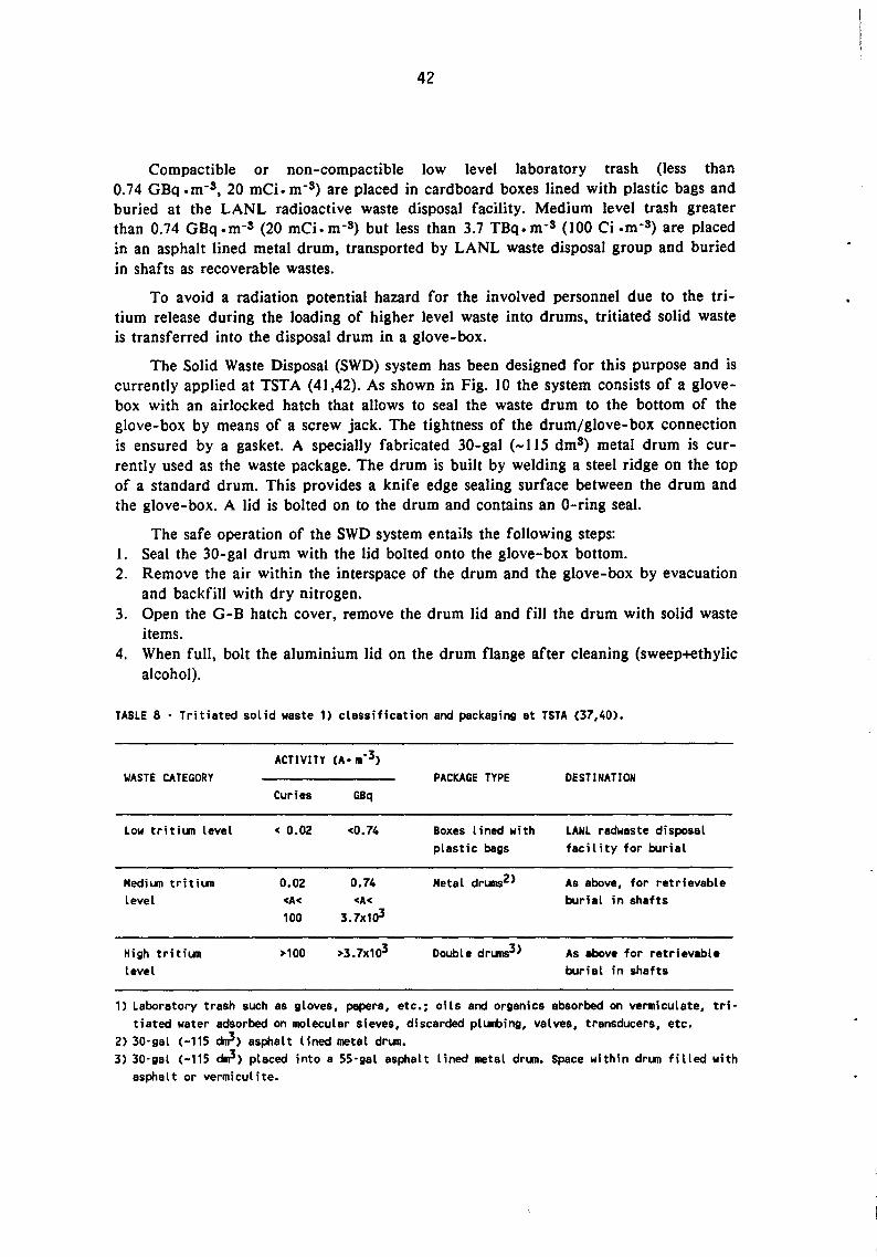
42
Compactible or non-compactible low level laboratory trash (less than 0.74 GBq .m-s, 20 mCi. m-3) are placed in cardboard boxes lined with plastic bags and buried at the LANL radioactive waste disposal facility. Medium level trash greater than 0.74 GBq.m-s (20 mCi.m-S) but less than 3.7 TBq.m-s (100 Ci .m-3) are placed in an asphalt lined metal drum, transported by LANL waste disposal group and buried in shafts as recoverable wastes.
To avoid a radiation potential hazard for the involved personnel due to the tritium release during the loading of higher level waste into drums, tritiated solid waste is transferred into the disposal drum in a glove-box.
The Solid Waste Disposal (SWD) system has been designed for this purpose and is currently applied at TST A ( 41 ,42). As shown in Fig. 10 the system consists of a glovebox with an airlocked hatch that allows to seal the waste drum to the bottom of the glove-box by means of a screw jack. The tightness of the drum/glove-box connection is ensured by a gasket. A specially fabricated 30-gal (-115 dm3) metal drum is currently used as the waste package. The drum is built by welding a steel ridge on the top of a standard drum. This provides a knife edge sealing surface between the drum and the glove-box. A lid is bolted on to the drum and contains an 0-ring seal.
The safe operation of the SWD system entails the following steps: I. Seal the 30-gal drum with the lid bolted onto the glove-box bottom. 2. Remove the air within the interspace of the drum and the glove-box by evacuation
and backfill with dry nitrogen. 3. Open the G-B hatch cover, remove the drum lid and fill the drum with solid waste
items. 4. When full, bolt the aluminium lid on the drum flange after cleaning (sweep+ethylic
alcohol).
TABLE 8 • Tritiated solid waste 1) classification and packaging at TSTA (37,40).
ACTIVITY (A• m·3) WASTE CATEGORY PACKAGE TYPE DESTINATION
Curies GBq
Low tritium level < 0.02 <0.74 Boxes lined with LANL radwaste disposal plastic bags facility for burial
Medium tritium 0.02 0.74 Metal drums2> As above, for retrievable level <A< <A< burial in shafts
100 3.7x10³
High tritium >100 >3.7x10³ Double drums3> As above for retrievable level burial in shafts
1) Laboratory trash such as gloves, papers, etc.; oils and organics absorbed on vermiculate, tri· tiated water adsorbed on molecular sieves, discarded plumbing, valves, transducers, etc.
2) 30·gal C-115 ~>asphalt lined metal drum. 3) 30·gal C-115 ~)placed into a 55·gal asphalt lined metal drum. Space within drum filled with
asphalt or vermiculite.

INTERS!' ACE
:BOLTED L[D
43
GL!JVEBOX
BCL TED COVER
~ASTE DRUM
~ S:CREV JACK
FIGURE 10 · Schematic of the Wastes Disposal System applied at TSTA
5. Close the G-B hatch cover, evacuate the space between the drum lid and the glove-box hatch cover and backfill with dry nitrogen several times.
6. Remove the (filled and lidded) 30-gal drum and check for contamination by swipe testing the surface of the lid. A low contamination, ( < I 000 dpm), is accepted at TST A as a current practice. According to the Los Alamos standard, a surface concentration less then 1000 dpm/100 cm2 is regarded as non-contaminated.
Final shipping containers are checked for outgassing with a portable monitor. The container surface activity is also checked by counting filter papers from smear tests performed before the container removal from tritium area for shipping.
After monitoring tritiated waste drums are transported by the LANL Waste Disposal Group to LANL Radwaste Disposal Site for ground burial (low level) or retrievable burial in shafts (medium and high level). Medium and high level wastes are transported in DOT approved shipping overpacks. The overpacks are reusable containers designed to protect the waste container from damage during an accident, but do not provide a gas tight seal. The waste containers are removed from the overpacks at the waste disposal site before being buried.
6.3 Mound Plant (MP)
The Mound Laboratory of Monsanto Research Corporation at Miamisburg, Ohio, now Mound Plant (MP) operated by EG&G has been processing tritium since 1958. Operations performed at this laboratory (43) include the routine handling of multigram quantities of tritium in various research development and analytical systems. These

44
operations produce large amounts of tritiated wastes that must be conditioned and disposed. According to ref. (44) in 1986 Mound has disposed of nearly 850 m3 of tritiated solid and solidified wastes including 16 drums of solidified high activity (100-1000 Ci • dm -3) water, 914 drums of solidified low activity ( 1-1000 microCi. dm -3).
Traditional solid wastes were packaged in 507 drum, 143 wooden boxes, 27 welded steel boxes. Typically solid wastes contain less than 1.3 GBq·m-3 (35 mCi • m-3).
Since 1972 the gaseous effluents generated by tritium handling operations at Mound are continuously processed by the Effluent Removal System (ERS) in order to remove tritium, tritium oxide and tritiated pump oil vapors before release to the environment. Appreciable quantities of tritium contaminated liquid wastes are collected as a result of gaseous decontamination processes. Tritiated liquids are also generated by vacuum and transfer pumps, processing and decontamination function, dry-box purification processes. Most of tritiated water is produced by the ERS with smaller quantities being generated in dry-box systems (43).
To minimize tritium release to the environment a considerable effort has been expended in areas of the safe management and disposal of tritiated liquid wastes. Facilities and methods have been developed at Mound for the safe handling and packaging of this liquid wastes.
The Liquid Waste Packaging Facility (L WPF) built at Mound in 1973 is designed to effectively reduce the hazard of handling liquid radioactive waste, both to the operating personnel during processing and to the environment after burial. The facility provides measurement, assay and packaging for burial of tritiated water and liquid organics under total containment conditions (43).
Tritiated liquid wastes are subdivided as shown in Tab. 9 according to their specific activity and their chemical nature. To meet burial ground criteria they are converted to solid forms by cementation or sorption on a solid matrix (44).
Low tritium specific activity water (see Tab. 9) normally includes mop and shower waters, decontamination solution and process cooling water (44). It is collected in two approximately 14 mS tanks prior to be processed. Twentyfive gallons (-94 dmS) of this water is transferred to a calibrated tank. A 17 H 55-gal (-210 dm3) drum already containing three 94-pound (-43 kg) bags of cement and one 50-pound (-23 kg) of FLORCQ(*) is placed in a fumehood located below the calibrated tank. As the water is added slowly, the contents of the drum are mixed mechanically and a second bag of FLORCO is added (44). The waste water is previously sampled and the total amount of tritium calculated to ensure that the package contains less than quantity allowed for the type A waste category (see Tab. 10).
High tritium specific activity water (Tab. 9) includes contaminated water resulting from the oxidation/adsorption process currently applied to strip elemental tritium from gaseous effluent streams. As described in refs. (43,44) the process for solidifying high activity tritiated waste waters consists of adding 25 dms of contaminated water into a 28-gal (-106 dmS) high density polyethylene drum having a thickness of 40 mil (-0.98 mm) and containing 24-gal (-90 dm3) of a I to 3 cement-plaster mixture. Water
(*) It is the commercial name of an aluminium silicate clay (Mount morillonite) put on the market by the FLORIDIN Co.

45
TABLE 9 · Tritiated liquid waste classification, solidification and packaging at Mound (44).
IJASTE SOLIDIFICATION PACKAGE TYPE DESTINATION CATEGORY Curies GBq PROCESS
Low T·activity <1 <37 Cement at i on4 > Standard water1> drun<7)
High T·activity >105 >37x105 CementationS> Multidrun water2> package8> Burial·grourd9)
High T·activity ~O.Sx105 ~18.5x1o5 Fixation on As above organics3> sorbent
materials6>
1) Mop and shower waters, decontamination and cleaning solutions, process loop cooling water. 2) llater from detritiation (oxidation/absorption process) of tritiated gaseous waste effluents. 3) Oils from punps and other organics. 4) By slow addition of water to a cement/"FLORCO" mix. with mechanical mixing and further addition
of 11 FLORC011 •
5) By slow addition of water to 1:3 mixture of cement/perlited gypsun plaster (11/C = 0.33) without mechanical mixing.
6) Vermiculite (org./verm. = 2) or "Absorbal" (org./abs. = 0.66). 7) SS·gal DOT specification 17 H druns qualified for a type A shipment. 8) 30·gal DOT specification 17 H steel drun, internally and externally coated with 0.25 to 0.75 mm
thick asphalt, lined with a 28·gal (-105 ~) DOT specification 2S HOPE drun and placed into a SS·gal DOT 17 H steel drum. The annular voids between the two drun are filled with asphalt and vermiculite. The overpack must by qualified for a type 8 shipment.
9) At Nevada Test Site.
is added to the cement-plaster mix at the rate of 0.5 to I dm3 .min-1 through a flexible polyethylene tube placed into the void space of the drum liner, on top of the cement-plaster mix (45). No mechanical mixing is necessary. The polyethylene liner is contained in a 30-gal (-115 dmS) steel drum coated with asphalt-bearing paint on the inner wall. To provide containment for the tritium and protection for the operator the 30-gal steel drum is sealed up against the bottom of a glove-box by means of a gasket.
When the complete solidification is reached, the bung is replaced on the polyethylene liner and sealed with a silicone rubber adhesive (GE RTV-102). The partially complete package is unsealed from the glove-box and lowered into a fumehood. The interspace between the top of the poly-liner and the lid of the 30-gal drum is filled with a non-hardening tar before the lid is replaced. The 30-gal package is then placed into a 55-gal steel drum, several inches of non-hardening tar having previously been placed in the bottom of the 55-gal drum. The 30-gal drum is centered into the 55, and the annular space is filled with absorbent material. Tar is also placed between the top of the 30-gal drum and the lid of the 55-gal drum. Fig. 11 shows a schematic view of this package.
According to the most recent information (45) high tritium activity water (>37xJ02 Bq·dm-3, 100 Ci·dm-3) is no longer routinely buried at Mound, where the processing of this waste is pursued for tritium recovery. Conversely the solidification
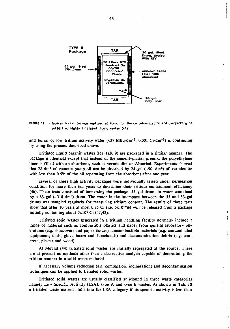
TYPE B Package
55 gal. Steel 17H Drum
46
TAR
25 Uter• HTO Unmixed On
50/50 Concrete/
Plaater
Organic• On V•rmlcullte
TAR
30 gal. Steel Drum, Sealed With RTV
Annular Space Filled With Abaorbent
28 gal. Poly-lln•r
FIGURE 11 • Typical burial package employed at Mound for the containerization and overpacking of solidified highly tritiated liquid wastes (44).
and burial of low tritium activity water (<37 MBq.ctm-3 , 0.001 Ci·dm-3) is continuing by using the process described above.
Tritiated liquid organic wastes (see Tab. 9) are packaged in a similar manner. The package is identical except that instead of the cement-plaster premix, the polyethylene liner is filled with an absorbent, such as vermiculite or Absorbal. Experiments showed that 28 dm3 of vacuum pump oil can be absorbed by 24-gal ( -90 dm3) of vermiculite with less than 0.5% of the oil separating from the absorbent after one year.
Several of these high activity packages were individually tested under permeation condition for more than ten years to determine their tritium containment efficiency ( 46). These tests consisted of immersing the package, 55-gal drum, in water contained by a 83-gal (-318 dmS) drum. The water in the interspace between the 55 and 83-gal drums was sampled regularly for measuring tritium content. The results of these tests show that after 10 years at most 0.25 Ci (i.e. 5xl0-4%) will be released from a package initially containing about 5xlO" Ci (47,48).
Tritiated solid wastes generated in a tritium handling facility normally include a range of material such as combustible plastics and paper from general laboratory operations (e.g. shoecovers and paper tissues) noncombustible materials (e.g. contaminated equipment, tools, glove-boxes and fumehoods) and decontamination debris (e.g. concrete, plaster and wood).
At Mound (44) tritiated solid wastes are initially segregated at the source. There are at present no methods other than a destructive analysis capable of determining the tritium content in a solid waste material.
If necessary volume reduction (e.g. compaction, incineration) and decontamination techniques can be applied to tritiated solid wastes.
Tritiated solid wastes are usually classified at Mound in three waste categories namely Low Specific Activity (LSA), type A and type B wastes. As shown in Tab. 10 a tritiated waste material falls into the LSA category if its specific activity is less than

47
II MBq (0.3 mCi) per gram. Strong tight packages such as drums or wooden boxes are required for packaging such a waste category but still more stringent requirements are to be met for the type A waste category with a specific activity up to 37 TBq (I03 Ci) per package. A type A package must be qualified for a type A shipment (see footnote 6 of Tab. 10). If the total tritium activity of the package is more than 37 TBq (103 Ci) a type B container or an overpack must be used. the latter being qualified as described in the footnote 7 of Tab. IO.
TABLE 10 · Tritiated solid waste classification and packaging at Mound (44).
WASTE CATEGORY
Low specific activity CLSA)1)
ACTIVITY CA • m·3)
Curies GBq
<0.3 mCi <11 MBq per gram per gram
>0.3 mCi >11 Bq
PACKAGE TYPE
Drums4> or wooden boxes5>
Containers qualified for
DESTINATION
per gram per gram type A shipments6> surial·gr~> <103 Ci
per package
Type s3> >103 Ci per package
<37 TBq per package
>37 TSq per package
Package or over· packs qualified for type B shipments7>
1) Compressible and combustible laboratory wastes such as plastic shoecovers, paper tissues, etc.; incompressible wastes such as piping and ductwork from outside the glove·box as well as decon· tamination debris such as concrete, plaster, wood, etc.
2> Uncombustible wastes coming from the interior of glove-boxes or fumehoods, i.e. contaminated equipment, tools, glove·boxes and fumehoods.
3) Hydrated cement matrices and absorbent materials arising from the solidification of tritiated water and liquid organic effluents.
4) 55·gal c-210 ~> DOT specification 17 H steel drums. 5) 48x52x87 inches (i.e. 1.2x1.3x2.2 m) wooden boxes. 6) A 50·gal C-190 am3> steel drum liner that is inserted into a 55·gal DOT specification 17 H or
17 C steel drum as well as welded steel boxes for largest waste items and eventually for too offgassing waste drums. A type A package must withstand (without affecting its integrity) a water spray, temperatures from ·40 to 130°F (·22 to 72°C), a four·foot drop test onto an unyielding surface, a compres· sion equal to five times the package weight and a pressure differential of 0.75 atmosphere.
7> For package of solidified tritiated liquid waste effluents see Tab. 9, footnote 8. A type B package must meet all type A criteria and withstand (without affecting its integrity) a 30·foot drop test, a 40·inch drop test onto a 6·inch pin and 800°C fire.
8> At Nevada Test Site.
Laboratory wastes (shoecovers. wastepaper, etc.) are considered to be non-offgassing and are packaged in 55-gal DOT approved 17 H steel drums. These wastes are compacted (VRF=4). and the resulting package is monitored for offgassing before it is shipped. Larger pieces of laboratory wastes such as piping or ductwork from outside the glove-box are placed into wooden boxes which met LSA but not type A criteria. These boxes are also monitored for outgassing before they are shipped.

48
Solid wastes coming from inside the glove-box or fumehood have a greater potential for offgassing and are more likely to exceed the LSA limit. Such waste materials are placed into a 50-gal (-190 dm3) steel drum liner that is sealed, placed into a 55-gal steel drum and monitored for outgassing. If the waste items are too large to fit into a drum a welded steel box must be used. These steel boxes are available in several sizes and all meet type A package acceptance criteria.
If single drummed laboratory waste is found to be offgassing, the drum is placed into a steel box. All steel boxes are also checked for offgassing before they are shipped.
6.4 Tritium Packaging and Shipping Requirements for new US Fusion Facilities
The starting of TFTR operation at the Princeton Plasma Physic Laboratory (PPPL,NJ) is planned for 1993 using tritium with deuterium as a fuel. The current tritium inventory limit fixed at the TFTR is 5 grams or 1.85 PBq (5xl04 Ci). The relatively small inventory of tritium allowed on the site requires that tritium be cycled through the facility as rapidly as possible to provide fresh quantities of tritium to be used in the TFTR.
Also CIT will employ tritium handling techniques very similar to those used at TFTR. Consequently TFTR's tritium handling equipment will be incorporated in its design and the same tritiated wastes handling procedures set-up by TFTR will be applied (37).
The amount of tritiated wastes which will be produced and handled at TFTR and CIT on a regular basis is expected to be comparable to the actual types and amounts currently produced at TSTA.
In addition to the delivery of tritium to TFTR for plasma fueling and the shipping of plasma exhaust (i.e. hydrogen isotopes with some impurities) the packaging and shipping of tritiated water sorbed on MS and other tritiated solid wastes will be a specific requirement envisaged for TFTR (37).
All the tritium handling systems of TFTR will take place in the Tritium Vault, the Tritium Waste Handling Area, and the Tritium Clean-Up System Room, that are located in the TFTR basement. Since all the installed equipment uses most area of the existing rooms it is therefore imperative that the tritium containers which are used are as small and easy to handle as possible and have a sufficiently large capacity.
The selection of containers to be used at TFTR must therefore take into account the container design and certification as well as transportation rules and regulations.
An additional requirement at TFTR is that shipments of tritium may not exceed 0.92 PBq (-2.5xl04 Ci), i.e. approximately 2.5 grams of tritium per container (37).
Furthermore in conformity with a specific requirement of the State of New Jersey shipments above 740 GBq (20 Ci) of tritium must be reported to the Department of Environmental Protection/Bureau of Radiation Protection for an approved transportation route.
To met tritium shipping requirements of TFTR, CIT and future full scale thermonuclear fusion devices many DOT approved containers are presently available in the U.S. (see Tab. I in Appendix IV).

49
A review study on tritium packaging has been carried out at PPPL specifically aimed at individuating suitable means to satisfy tritium transport needs of TFTR (37,49). The conclusions of the study on tritium containers for TFTR published in 1988 (49) were that: I. Tritium must be delivered in LP-12 containers. 2. Plasma exhaust gas would be best handled by using the Oak Ridge getter bed con
tainer. 3. Tritiated water should be transported in DOT approved containers, under a solidi
fied state, i.e. after it has been adsorbed on molecular sieve beds. 4. Tritiated solid waste (i.e. room trash, clothing and contaminated equipment) will be
segregated and classified as Low Specific Activity or Type A or Type B wastes and transported to a waste disposal facility in standard strong-tight waste containers.
At TFTR the LP-12 container will be used for incoming shipments of tritium, while outgoing shipments could be handled by one of other containers outlined in Tab. 1 of Appendix IV.
All these containers are DOT approved so that they can be used for transporting tritium from fusion facilities to another site for reprocessing or disposal. This is a significant advantage because in this context the DOT regulation for radioactive material containers is any how a final bottleneck point which must be dealt.
Specific and general tritium packaging requirements are defined by the US Department of Transportation (DOT) (50).
The certification of solid waste shipping containers according to the DOT requirements include maintenance of integrity during specified temperature excursions, drop tests, compression tests, pressure differential and water spray. As indicated in Section 6.3, Tab. 10, the certification will depends on the specific and/or total tritium activity typical of the waste material placed in the container.
The movement of tritium gas and plasma exhaust gas to and from the fusion facility may be done by air freight or ground transportation.
In the case of tritiated gas in approved 12 dms or 50 dms containers, shipment by air freight is a common method of transport, being the air transportation usually favored over ground transportation, for economic reasons. In some cases for land transportation the container must be transported on a truck which is specially dedicated to that shipment and an "Exclusive Use Rate" is charged for the vehicle.
All tritium contaminated radioactive waste transported on public roads which contains more than 1.1 PBq (-3xl04 Ci) per container is designated as "Highway Route Controlled Material" and requires a specially trained driver.

50
7. CANADA
No particular problems have arisen in Canada for the management of radioactive wastes produced by the operation of CANDU (CANadian Deuterium Uranium) PHW reactors, because of tritium content of such wastes. Therefore also in this country no specific waste management procedures have till these last years been applied other than those currently envisaged for transporting, processing and storing typical Candu type reactor wastes.
For the next years however the production of considerable amounts of tritiumcontaminated wastes including highly tritiated liquids and solids is expected in Canada, due to the operation of the two presently largest industrial scale tritium removal plants, i.e. the Tritium Removal Facility at Darlington and the Tritium Extraction Plant at Chalk River.
7.1 Wastes from Candu Reactor Operation
All CANDU reactors, operated by utilities in Ontario, Quebec and New Brunswick, use natural uranium fuel and heavy water as moderator and coolant. Tritium is produced in both heat transport and moderator systems by neutron activation of deuterium atoms while in the reactor core, with consequent ever-increasing tritium concentration in all heavy water systems of such reactors (51,52).
The management of canadian radioactive wastes is shared between Atomic Energy of Canada Limited (AECL), a federal agency, and the provincial utilities that are responsible for the management of low and intermediate level wastes. Due to its committed nuclear capacity of 13,600 MWe, Ontario Hydro is the major producer of radwastes.
CANDU reactor operating wastes are composed of a wide variety of materials and shapes. A major volume component is "non-radioactive" housekeeping wastes from areas of the station in which radioactivity is present; these materials are procedurally treated as "radioactive". Typical reactor wastes include discarded protective clothing, temporary floor coverings used for contamination control, mopheads, wood, vermiculite, heavy water purification media such as filters and ion exchange resins, solidified liquid waste, discarded piping, valves, tools and other hardwastes arising from the maintenance of reactor systems (51,52).
Waste segregation into combustible, compactible, and non-processible categories is carried out at the stations. In view of transporation to the waste site in 1 m3 type A metal containers, wastes are collected, packaged and sealed in clear polyethylene bags (53).
In addition to the miscellaneous wastes, also tritiated heavy water purification media such as filters and ion exchange resins require storage. Spent filters are dewatered, sealed in metal containers and shipped to the waste storage site in type B transportation flasks. Most of the spent ion exchange resins are handled in bulk and are effectively detritiated by dedeuteration (water washing) and dewatering and shipped to the storage site in 3 ms carbon steel cylinders (53).
Only a small volume of low specific activity tritiated aqueous waste is presently generated by Ontario Hydro which is diluted to very low levels before release to the environment.

51
Ontario Hydro operates the transportation, processing and storage of its own reactor wastes. The Radioactive Waste Operations Site (RWOS) at the Bruce Nuclear Power Development (BNPD) site located in Tiverton, Ontario, about 250 km northwest of Toronto and operated by Ontario Hydro, is specifically dedicated to radwaste volume reduction, packaging and storage of reactor wastes (51 ,52).
At the Bruce RWOS the combustible and compactible wastes are processed into the Waste Volume Reduction Facility (WVRF) whereas the non-processible wastes are sent directly to the Waste Storage Facilities (52).
7.1.1 Waste Volume Reduction Facility (51-53)
The WVRF at the Bruce RWOS, is equipped with an incinerator, a baler, a compactor and some storage facilities. No significant volumes of tritiated liquid waste requiring solidification are produced in CANDU reactors, so that an immobilisation system is not normally required.
Combustible wastes with a dose rate of less than 0.6 mSv ·h-1 (i.e. 60 mr ·h-1) are volume reduced (50: 1) by incineration and, in doing so, the small quantity of tritiated contamination is eliminated from wastes. No attempt is made to recover the tritium released from wastes during incineration, the incineration exhausts being discharged directly to the stack. The tritium free incinerator ash is unloaded into 2.5 m3 sealed metal containers which are placed in engineered storage structures.
Compactible wastes of less than 2 mSv h-2 (i.e. 200 mr · h- 1) are volume reduced by mechanical compaction. As with the incinerator, no attempt is made to recover tritium released into ventilation system exhausts during the baling or compacting processes. The plastic bags containing the waste are compacted into 0.4 m3 cardboard boxes w .. hich are then secured with steel straps and double plastic bagged.
Baler and compactor exhausts discharge directly into the exhaust stack of the building ventilation system, thus minimizing occupational dose.
Ventilation system and incineration exhaust stack discharges are monitored for tritium and gamma-emitting radionuclides.
Tritium emissions from the WVRF, mainly controlled by limiting incineration to wastes with a maximum dose rate of 0.6 m Sv · h-1, are less than 0.1% of the Derived Emission Limit of 5.2 PBq (1.4xi05 Ci) per week (53).
A typical flowsheet of reactor solid waste management is shown in Fig. 12 taken from ref. (51).
7.1.2 Waste Storage Facilities (51-53)
The following operational criteria are applied by Ontario Hydro to operate its own radwaste storage facilities at the Bruce RWOS (51,52): I. All radioactive materials are stored in a retrievable manner in facilities having a
design lifetime of 50 to 100 years. 2. No radioactive materials are placed directly in soil; engineered structures are used. 3. Only solids are placed in storage; liquids, which are potentially much more mobile
and hence harder to isolate from the environment, are first immobilised.

Purifocation System Filters
Miscellaneous lncinerable
Waste
Miscellaneous Compect8ble
Waste
Miscellaneous Non-Processable
Waste
Spent Rasin In DzO
Systems
Spent Resin in H20
Systems
Moscellaneous Reactor
Core Components
52
r-1
------------, I
I I I I Drip. I I Type 'B' r ln.St8tion I I t Cent I Truck _
Shielding Transportation Flasks
--.. 1 Flask I
I
..... ·~ I I I ~ .....,I
r----------1 I I Incinerator I
.. I I
r-------. I I I I I 1-1- I
ln.St8tion I Type A Truck
orLSA I I Baler Transporter I P1Ck8ging r+-
I Compecter --... I I I ln.St8tion Solid I I I Wute Management I I Bruce NPO Wlaste
I Area I I Volume Reduction Facility
[ __ -- -- ...J L ________ ...J
-...
Type'S' f-. Transportation
I 1/S L w 1/S I Flask
Flask Flask I OzO ....... ~ Recovery .... ....... ln.St8tion Bulk
Pope lone Wet ~ Resin Storage Container
Pipeline
I Type 'B' I 1-------------1 Transportation 1--------...:T.:.•u;:;;ck:.;,;.... _____ ,. I Flask I •
Storage
Storage
Storage
Storage
Storage
Storage
FIGURE 12 Reactor solid waste management flowsheet (51). Waste storage is carried out at Bruce
NPO Waste Storage Facilities.

53
4. All waste emplacement is treated as an interim storage. A certain component of the waste stored may outlive the expected lifetime of the storage structures and hence may need to be retrieved and sent to ultimate disposal.
Various types of engineered storage facilities are used to provide during the interim storage multiple confinement envelopes between the waste materials and the subsurface environment.
Storage structures have been constructed on a dense clay till deposit. The clay till provides a natural confinement barrier in which low permeability (lo-6 to 10-7 em ·s-1), and geochemical retardation ensures that any radioactivity escapes from the engineered storage facility and under-drainage system will move very slowly. Figs. 13 to 16 show a view of the different engineered storage facilities. Their features may be summarized as follows (51-53):
- Concrete trenches (Fig. 13) Concrete trenches are shallow inground reinforced structures designed to receive processed and non-processible low level reactor wastes having radiation fields of 10 to 50 m Sv ·h-1 (1-5 rem ·h-1). Because of the modest radioactivity levels much of this waste can be manually loaded. On completion of loading, 0.31 m thick precast concrete lids are sealed to the trenches using neoprene gaskets. The trench internal dimensions are 3 m wide x 3 m deep x 40.3 m long and each trench is divided into three compartments. Trench walls are 0.38 m thick. The bottom of each trench compartment slopes to a sump and standpipe to permit water detection and removal. A granular filled interspace is provided between the trench and the dense, low permeability clay till underneath. This interspace is serviced by a monitored underdrainage system. Surface drainage collection/sampling and ground water sampling systems are also provided.
- lnground containers (IC-2, IC-12) Concrete tile holes (0.69 m i.d. by 3.5 m deep) have formerly been utilized for highly radioactive wastes such as cartridge filters and packaged ion exchange resins having a typical contact radiation field of less than 1 Sv ·h-1 (100 rem ·h-1). After waste loading tile holes were backfilled with a high slump concrete to form a monolithic cylindrical structure. However these facilities are no longer in use as they have been replaced with inground containers of the IC-2 type. Typically they consist of two concentric cylindrical steel liners (0.6 m and 0.76 m diameter and approximately 7.65 m long) placed into an inground non-shrink concrete envelope. Typical IC-2 features are illustrated in Fig. 14. Other storage facilities also no longer is use are the quadricells. These above ground structures (6.0 m square by 5.5 m high) divided into four cells and primarily used in the past for bulk spent ion exchange resins were also designed for the eventual storage of high level reactor core components. Proving to be too expensive, these structures have been replaced with inground containers of the IC-12 type. Typically they consist of a welded cylindrical steel liner (approximately 1.7 m internal diameter x 8.2 m deep) placed into an inground concrete envelope, where four 3 m3 bulk resin containers can be loaded together with a terminal plug for shielding. A typical IC-12 arrangement is schematically illustrated in Fig. 15.
Storage building (Fig. 16) The low level waste storage building (LLSB), is an above ground prestressed concrete structure, 50 m long x 30 m wide x 8 m high, used primarily for incinerator

Multiple Envelopes of Control
54
S =Sampling Location
FIGURE 13 - Shallow sub-Surface Multiple Envelopes of Control.
FIGURE 14 - Inground Container IC-2.
Tap Ctwer/_ Pipe Cap
. 0
0 . -1~==~==~111)" - Samplng Pipe
.. a
0
.. 0
eoncrete ~ : I ~ ~-l!:t:==t:=:::::I::II.: 0
0
1r::- Typical Waoto Loading !-{ Four 3 m' Bull Reeln Coi1ta1nen1
.. 0
:.,====r=~~~--:---i"cll Welded steel Uner
(l<pprox. 5' ff' Ilia X 27' Long) . 0
FIGURE 15 - A Typical IC-12 Arrangement.

55
FIGURE 16 - Perspective view of low-level storage building.
ash containers and baled waste. It is equipped with fire extinguishing, lighting, smoke detection, ventilation and drainage systems. All wastes are packaged in plastic or in sealed metal containers to minimize the spread of contamination. Inside the LLSB the free standing metal containers are stacked to a height of 6.25 m. Loading of the wastes is accomplished by a front end loading vehicle similar to a forklift. Only wastes which exhibit radiation fields less than 2 mSv · h · 1 (200 mrem · h-1) will be loaded and stored in the LLSB. The LLSB is designed to complement rather than to supplement the roles of the other structures in use at the site. The use of the storage building for the low level waste will allow the capacity of the inground trenches to be reused once the waste in this category, which is stored there, is retrieved and placed in the LLSB. The Low Level Storage Building (LLSB) is monitored for tritium and gamma-activity levels. The limit for airborne tritium level in the LLSB is typically 37 kBq · m·3 (I J,.£Ci • m·3). Respiratory protection is used when airborne tritium level exceed the 370 kBq · m-3 limit (53).
7.2 Wastes from the Darlington TRF Operation
In the late 1970's Ontario Hydro decided to construct a centralized Tritium Removal Facility (TRF) at the Darlington NGS site to reduce the level of tritium in the heavy water inventories of all its own nuclear generating stations, with a consequent beneficial reductions of the occupational dose and tritium environmental emissions. The early operating phase of the Darlington Tritium Removal Facility (DTRF) has started in 1988 after its commissioning. At maturity the DTRF will extract about 740 PBq ·a-1 (-20 MCi ·a-1) of tritium primarily from the moderator (D20) of all CANDU nuclear reactors (54). The elemental tritium extracted in the DTRF will be immobilised using containers with titanium metal getters, containing about 19 PBq (-500 kCi) each and placed into a long term storage vault. Portions of tritium will be packaged and sold for commercial applications (54).

56
The operation and maintenance of the DTRF will indeed result in the generation of tritiated wastes. Tritium will be the dominant isotope of such wastes. The contribution of all other radioisotopes usually produced in a typical nuclear generating stations (i.e. fission and corrosion products) is expected to be negligible.
In view of the DTRF operation Ontario Hydro has been forced to consider in detail what kind of tritiated wastes are expected to be generated by such a facility as well as what processing facility and procedures will be required for their safe immobilisation, packaging and storage. An estimate of tritiated waste activities and volumes expected from the operation and maintenance of the DTRF is reported in Tab. 11 & 12 derived from data reported in refs. (53,54).
The estimated volumes of tritiated wastes reported in these tables are based .on the design conditions foreseen for the various DTRF systems. But during an actual operation waste generation may be different because of the various operational and maintenance strategies, so that the mentioned volumes are to be considered only as indicative.
The following management procedures have been proposed (54) for such wastes. Tritium present as T 2 and T 20 in the DTRF building atmosphere (because of small chronic gaseous leaks of the various DTRF subsystems) will be normally discharged and the DTRF Building Ventilation System (BVS) through the stack into the environmental atmosphere. Chronic tritium releases into the BVS exhaust will be monitored prior to discharge via the stack, whereas abnormal tritium releases into DTRF rooms will previously be cleaned up by the Air Clean up System (ACS).
However the ACS shall be bypassed when the accidental concentration of hydrogen isotopes in its inlet stream is higher than 6%. This is to be done in order to prevent the formation of an explosive mixture in the ACS equipment even if these situations are deemed to be very rare events. At the site boundary the individual dose expected from such uncontrolled releases will be in any case less than 0.1 microSv (0.0 1 mrem).
As to the waste water collected in the D20 collection tank they will be sampled and handled as follows (54): - water from the Tritium Immobilization System glovebox cleanup system and from
the recombiner are sent automatically to the DTRF Feed Water Tank for processing. all remaining water streams which have low activity levels are sent in one of two directions depending on their deuterium content, namely: a) if the D20 concentration is less 0.3%, the waste water is forwarded to the
Station's Active Liquid Waste Collection/Drainage System for discharge provided the activity level is below 0.22 GBq ·dm-8 (5.9 mCi ·dm-8) and the discharge will not exceed 0.9% of the Derived Emission Limit (DEL) for the month;
b) if the D20 concentration is greater than 0.3%, the waste water is forwarded to one of the D20 upgraders for processing.
Waste light water, such as from the decontamination of commercial tritium containers, will be directed to the station Active Liquid Waste Collection/Drainage System for discharge. This water is expected to have a typical tritium concentration of less than 37 kBq (1 microcurie) per litre.

TABLE 11 - Estimate of tritiated liquid waste arisings expected from Darlington TRF operation (54).
WASTE GENERATING GENERATING T·ACTIVITY ESTIMATED MAX ITEM OPERATION SYSTEM OR AREA LEVEL PRODUCTION RATE REMARKS
OR EQUIPMENT <ml•a" 1>
o2o Accidental DTRF extraction High Produced by abnormal TRF subsystem operation. leakages subsystems Collected by the DzO Collection System and
or spills Stored in a tank.
Condensates Molec. Sieves ACS Low to High Collected in a tank of the downgraded o2o Trans-Regeneration fer System. Returned to o2o Upgrader.
T20 adsorber TAP High 35 No direct contact with T2• In case of T2 leakage, Regeneration GBCS T2 is present. Returned to TRF feed tank.
Decontam. lTC TAP Low1> 200 Low activity water from decontamination of sales H2o Decontam. Decontam. containers. Directed to the Active Liquid Waste
c..n Station Drainage System for discharge. ......,
Electrolyte Electrolyser OMS Low to 0.025 Waste solution from electrolyser to be eventually Solution Solution Meditd) processed for o2o recovery and then i nmobil i sed (25 wX KOO) Replacement for storage as solid wastes.
Oils Vacuun P~ Low to High 0.075 To be immobilised prior to storage as solid Maintenance waste. & Periodic Oil Changes
• TIS & TAP Low (TIS & TAP) 0.005 (each) Low exposure to tritiun normally expected. High vacuun Mediun to High 0.02 (tot.)3> P~et (TAP)
·CD Low to High 0.01 (each) Low degree of T·contamination expected. If
Diffusion 0.03 (tot.)4) T-leakage into cryogenic cold box occurs Vacuun T·activities as high as 1 to 1.8 TBq·dm-3 p~ (30 to 50 Ci·dm-3) may be present.

TABLE 11 - Cont.ed.
1./ASTE ITEM
GENERATING OPERATION
GENERATING SYSTEM OR AREA
OR EQUIPMENT
- CD Rotary Backing p~
• TIS & TAP Air-lock Evacuat. p~
T·ACTIVITY LEVEL
low to High
Low
ESTIMATED MAX PRODUCTION RATE
<ml·a-1)
0.005 (each) 0.015 (tot.)
0.005 (each> 0.010 (tot.)
REMARKS
As above.
Low exposure to tritiun normally expected.
1) From 0.37 to 55 MBq·m-3 (0.01 to t.5 mCi·m-3) depending on the I'Uib!r of TAP sales containers and average level of tritiun surface contamination. Typically a concentration of less than 37 MBq·m-3 is expected.
2) From 18 to 37 GBq•kg-1 (0.5 to 1 Ci•kg"1). If the OMS uses virgin heavy water the tritiun content of the electrolyte section will be negligible. 3) Up to 550 GBq•dm-3 (15 Ci·dm-3). 4) Normally non-contaminated. Up to 0.74-1.11 TBq~·3 (20-30 Ci·dm-3) in the event ofT-leaks into cryogenic cold boxes. ACS = Air Clean-up System. BVS = Building Vent il. System. CD = Cryogenic Distill. System. OMS = Dz Make-up System. GBCS = G·B Clean·up System. LTC = Low Tritiun Colunn (CD). HTC = High Tritiun Colunn (CD). lTC = Immobilisation Tritiun Container. TAP = Tritiun Application Plan. TIS = Tritiun Immobilisation System (TiT3).
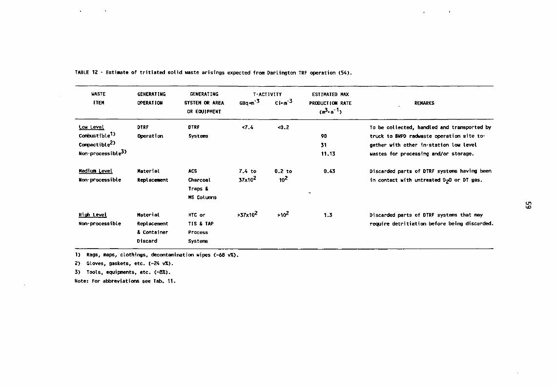
TABLE 12- Estimate of tritiated solid waste arisings expected from Darlington TRF operation (54).
~ASTE
ITEM
Low Level Combustible 1> Compactible2>
Non-processible3>
Medium Level
Non-processible
High Level
Non·processible
GENERATING
OPERATION
DTRF
Operation
Material
Replacement
Material
Replacement & Container
Discard
GENERATING
SYSTEM OR AREA
OR EQUIPMENT
DTRF
Systems
ACS
Charcoal
Traps & MS Columns
HTC or
TIS & TAP Process
Systems
T·ACTIVITY GBq·m·3 Ci• m·3
<7.4 <0.2
7.4 to 0.2 to
37x102 102
>37x102 >102
1) Rags, maps, clothings, decontamination wipes (-68 v%).
2) Gloves, gaskets, etc. C-24 v%).
3) Tools, equipments, etc. (-8%).
Note: For abbreviations see Tab. 11.
ESTIMATED MAX
PRODUCTION RATE
cml•a · 1 >
90
31
11.13
0.43
1.3
REMARKS
To be collected, handled and transported by
truck to BNPD radwaste operation site to·
gether with other in-station low level
wastes for processing and/or storage.
Discarded parts of DTRF systems having been
in contact with untreated D20 or DT gas.
U"' 1..0
Discarded parts of DTRF systems that may
require detritiation before being discarded.

60
Approximately 22 kg ·a-1 of electrolyte solution (25 w% KOD with a tntiUm content of up to 0.5 - 1 Ci ·kg-1) will be produced by the semiannual replacement of the 11 kg holdup of the D2 Makeup System electrolyser. By using the virgin heavy water to make up the electrolyte solution, the tritium content of such a solution becomes negligible. A treatment of this highly caustic solution is planned entailing the absorption of the liquid to minimize dispersion and the containerization of the medium into HDEP. Furthermore it may be economically viable to recover heavy water from the electrolyte prior to storage.
Up to 75 dm8 per year of waste vacuum pump oil will be produced in total due to the maintenance vacuum pumps of the LTC, HTC, TIS and TAP system (see Tab. 11). Tritium concentrations of up to 1.85 TBq ·dm-8 (50 Ci ·dm-8) are possible for these oils if they have been in contact with tritium. Waste oils will require immobilisation prior to being sent to Bruce Radwaste Operation Site for storage as solid wastes.
Due to the low tritium contamination of low level solid wastes from DTRF (tritium activity levels are similar to general station LL W), this type of waste should be handled the same way as other similar type radioactive solid waste produced in the station. Local collection stations should be set up at the DTRF Building and the existing in-station solid radioactive waste collection routes should be expanded to include these stations. No segregation of low level wastes produced by the DTRF from other in-station low level wastes is required (54).
The low level tritiated solid waste generated by the DTRF, should be transported by truck to Bruce Radwaste Operation Site together with other low level wastes produced by the Darlington NGS, for processing and/or storage in trenches or in the Low Level Storage Building (LLSB).
Since the estimated volume of medium and high tritium level solid wastes are very small (see Tab. 1 0) it appear convenient to group them for the subsequent treatment or processing. They should therefore be collected together, sealed in double plastic bags and temporarily stored in closed drums or containers, in a designated storage area. When containers are full these wastes should be processed or further packaged and sealed at the Darlington site before being sent to the Bruce Radwaste Operation Site for final storage. The packages for transportation to Bruce site (Type A or B overpacks) as well as the final disposition into the various waste storage facilities of the site (see Section 7.1) will depend upon the activity level and the method of immobilisation/packaging.
At Darlington a TRF associated waste processing facility aimed at the application of selected waste immobilisation and packaging techniques is therefore required for the management of tritiated liquid wastes as well as medium/high level tritiated solid wastes. The procurement of this facility has been recommended by the Nuclear Management Department of Ontario Hydro as one of the main specific actions for a new approach to the management of tritium bearing waste in Canada (54).
Within the perspective of finding proven techniques and effective barrier materials suitable for the safe storage or disposal of highly tritiated wastes, an extensive R&D programme has been initiated at Ontario Hydro Research Division since late 1984 (52). When the work started, Ontario Hydro had a policy to develop low and intermediate level waste disposal facilities by 1992. Although in 1987 the early disposal
" '

61
concept was abandoned in favour of a continued retrievable storage, the Ontario Hydro research programme continued with the intent to condition and package tritiated wastes in such a way that they did not have to be further processed for later permanent disposal.
Results of the experimental work have been published in some Ontario Hydro Research Division reports (55-59) and presented at some Topical Meetings (53,59). A survey of these results has also been performed at JRC Ispra (I).
More recent information received from Ontario Hydro (60) confirm that the tritiated waste management strategy to be applied at Darlington in the new waste processing facility will reflect the main significant conclusions attained by the previous Ontario Hydro experimental work on tritiated wastes, namely: - The immobilisation (i.e. sorption or solidification) of tritiated liquid wastes retards
the release rate of tritium from the waste not so adequately as expected from a completely effective barrier. Therefore liquid waste immobilisation is recommended only to prevent dispersion of the package contents, should the container be damaged accidentally.
- The primary effective barrier against tritium loss from the package is therefore the container.
- Based on the permeability of HT and HTO through various plastic container materials, I em thick high density polyethylene (HOPE) has been chosen as the primary container material for all tritiated wastes.
- By packaging highly tritiated metallic wastes into I em HOPE containers and backfilling the void volume with moist sand the tritium release from the package is further reduced by a factor of 30, i.e. from 3xi0-3% per day to lxi0-4% per day.
The experimental work on tritiated wastes is continuing at Ontario Hydro, mainly focused on the optimization of the sealing of the HOPE primary container as well as on the minimization of the gas production by radiolysis. This is in order to reduce the risks of unacceptable overpressures inside the container (60).
At present no acceptance criteria based on a fixed limit of tritium outgassing rate are envisaged for an application to tritiated waste packages.

62
8. SUMMARY
8.1 France
In addition to tritium amounts currently recovered since 1970 at the "Institute LAUE-LANGEVIN of Grenoble from heavy water of high flux reactors and other sources, considerable amounts of elemental tritium have certainly been processed in France also for military purposes into the facilities located on the sites of the Nuclear Centres of Valduc and Bruyeres le CMtel. In these research centres, operated under the responsability of the Direction of Military Application (DAM) of the French Atomic Energy Commission (CEA), the large amounts of tritium contaminated wastes there generated, have required the set up of specific waste management strategy and practices. On this matter very interesting information have been obtained at the "Journees du Tritium" held in 1986 at Dijon (4-9, 11-13).
The strategy and practices presently under application in France for managing tritiated wastes from tritium handling facilities of both centres can be summarized as follows:
- The CEN-Va1duc is the only central site for temporary storage of all french tritiated wastes generated by specific tritium handling facilites.
- Most french tritiated wastes are produced under a final solid state. Even tritiated gaseous waste streams lead, after the detritiation process, to tritiated liquid condensates that, if not reworked for tritium recovery, are usually solidified before wasting.
- According to their contamination "history" and with the help of outgassing rate measurements, french tritiated solid wastes are subdivided into "recyclable" and "non recyclable". This is to distinguish highly tritiated materials, for which a detritiation treatment is justified for tritium recovery purposes and/or management cost savings, from slightly tritiated wastes for which such a treatment cannot economically be justified.
- "Non recyclable" tritiated solid wastes, are waste materials having a tritium outgassing rate lower than 2.2 GBq· d-1 ·drum-1 (60 mCi ·d-1 •drum-1). The lower limit of these wastes is represented by the surface activity value of 3.7x1 o-3 kBq • cm-2
( -1 o-• microCi. cm-2). Below this limit value wastes are considered as non-contaminated. The boundary limit between "recyclable" and "non recyclable" tritiated aqueous effluents tends to decrease to a value below 3.7 TBq ·dm3 (-100 Ci •dm-3)
because of their radiotoxicity.
- "Non recyclable" slightly tritiated liquid and solid wastes are managed in order to ensure the safest and most economic conditions for a long term storage. Liquid effluents are fixed on sorbent matrices to give solid wastes that are then packaged into standard drums. No encapsulating media are utilized to immobilise solid wastes into drums. This is in order to keep open for the future the application of an optimized immobilisation procedure, if the choice of the ultimate disposal route would finally be decided.
- "Recyclable" highly tritiated wastes are submitted to detritiation treatments with the aim of recovering and recycling their tritium content. This will also render less hazardous and more economic the storage of resulting detritiated wastes.
63
Tritiated hydrogen present in gaseous effluents from experimental tritium circuits is purified from impurities (e.g. CH3 T, C02) and then recovered by isotopic separation and enrichment processes. Tritiated hydrogen present in gaseous effluent containing air is catalytically oxidised to HTO vapor which is adsorbed on MS and periodically desorbed and condensated. The condensate is then treated to reduce HTO to HT by electrolysis or chemical reaction on metallic U catalyst at 500°C. Depending on their tritium concentration a previous step of isotop-ic enrichment could be applied to the liquid phase before the reductions. The gaseous stream resulting from the HTO reduction is then directed to the tritiated gaseous effluent treatment. Highly tritiated metallic wastes such as stainless steel, alloys, brass, nobel metals, etc. are detritiated, i.e. depleted of permeated tritium by thermal treatments. These treatments include waste heating under depressure and inert gas stream as well as melting under vacuum. Organic waste materials such as organic components of valves, etc. are detritiated by degassing into an oven. All tritiated gases released by such wastes are sent to the gaseous effluent treatment. The best advantages in terms of thermal detritiation of metallic wastes can be achieved by the melting process. In addition to a significant reduction of tritium contamination at the surface and permeation into the bulk of the waste item, after such a treatment a better homogeneity in the distribution of the residual tritium can also be attained.
- After drumming and categorization by outgassing measurements slightly tritiated waste packages are long term deposited in suitable stores which have different features according to the category of drummed wastes being destined to them.
- Slightly tritiated solid wastes with a tritium surface activity lower than 1.85 kBq ·cm-2 are packaged and transferred for long term storage at CSM, la Hague, provided the following specifications are met: . non-encapsulated waste packages with a tritium specific activity and a tritium out
gassing rate equal or below 7.4 GBq ·t-1 (-0.2 GBq ·t-1) and 5xlo-3 % d-1 ·drum-1 respectively;
. cemented wastes and internally lined epoxy packages with a tritium specific activity within 7.4-74 GBq ·t-1 (0.2-2.0 Ci ·t-1) and a tritium outgassing rate equal or below 5xl0-4% d-1 ·drum-1.
- The sea dumping is an option potentially applicable for disposing of also fusion wastes, but it is for the moment impracticable for political and social reasons. Because of the strong pression of a part of the public opinion on the respective national governments its application for fission wastes has been halted in 1983 following the moratorium decision of the majority of countries that had partecipated to the preceding sea dumping campaigns.
- The waste disposal under sea-bed as well as in deep repositories are other alternative options whose application cannot be envisaged at short term. This is primarily due to several problems entailed by the implementation of such options, namely the high investment and operational costs and the long time to identify, investigate and qualify the suitable geological sites. Another constraint will be the degree of public acceptance. The importance of this aspect is well demonstrated by all the obstacles encountered by ANORA in developing a fission waste management strategy based
64
on a deep disposal route. Following a moratorium announcement of the french government, ANORA has been forced to halt any exploratory activity concerning the identification and qualification of candidate underground sites for disposing of fission wastes in a deep geological repository. This was essentially due to the strong pressure on the french government of some groups representing the population living in the regions where candidate sites were located.
8.2 FRG, UK and Sweden
No specific strategy and practices have so far been set-up in FRG, UK and Sweden which could be applied for managing tritium contaminated wastes that will be generated from future thermonuclear fusion reactors. At present the only possibility of facing this problem is that of extending the existing management practices, currently applied for fission wastes, to such new wastes. On the other hand one has to point out that most national strategies for the management of fission wastes are continually evolving, due to a continuing process of review to which they are currently submitted. It is likely however that the situation will substantially change in the near future for some countries. This will be due for instance to the starting of the operation of the tritium Laboratory of Karlsruhe, and the progress of the research activities performed in Sweden, in the framework of the European Fusion Technology Programme (see sections 3 and 5).
Furthermore studies have been undertaken at Culham and Harwell laboratories to investigate the options for treatment, storage, transportation and disposal of differing waste streams expected from the 0-D and 0-T phases of the JET plasma operation. The construction of extra facilities to support waste management and radioactive maintenance operations inherent to the 0-T phase has been planned. Its completion is envisaged before the introduction of tritium into the machine.
8.3 United States
Since several tens of years multigram quantities of tritium have been routinely handled in USA for tritium research, development and analytical purposes especially at the Tritium Research Laboratory (TRL) of Sandia Livermore Laboratories (Livermore, California), Tritium System Test Assembly (TSTA) of Los Alamos National Laboratory (Los Alamos, NM) as well as at Mound Plant (MP) operated by EG&G (Miamisburg, Ohio).
Suitably tailored waste management practices are applied at these sites for the safe conditioning, containment and transportation of tritium contaminated wastes generated from their tritium handling systems.
Waste conditioning and packaging procedures applied at Sandia TRL, TST A and Mound are here summarized. The most significant data have been collected in Tab. 13, so that a comparison between the various practices can be made.
1. SANDIA TRL (Livermore)
- Tritiated gaseous effluents are minimized by the use of Gas Purification System (GPS) and the Vacuum Effluent Recovery System (VERS). The former decontamination system is used to remove tritium and tritiated water from sealed glove-box atmosphere while the latter one to remove tritium, tritiated water and

Table 13 Comparison among conditioning procedures and packaging containers applied for tritiated waste management at some US tritium handling installations.
SANDIA TRL TSTA MOUND PLANT
WASTE T·Act. CONDITIONING PACKAGE TYPE OVERPACK. T·Act. CONDITIONING PACKAGE TYPE OVERPACK T·Act. CONDITIONING PACKAGE TYPE OVERPACK. CATEGORY MODE MODE MODE
LIQUIDS
Low Activ. Effluents · water Sol idificat. 55·gal None 5) Sol idificat. 30·gal None 9) Solidificat. 55·gal None
(MS?) drum 4) (MS) drum 3) (cement) drum 4, 10) · oil 1) Solidificat. 55-gal None
(vermiculite drum 4) - - - - - -or equiv.)
High Activ. Effluents - water n.a. Sol idificat. 2 an3 vessel 55-gal 6) Sol idificat. 15-gal or 55-gal 11) Solidificat. 30-gal drum 3) 55-gal
(MS) into a second drum (MS) 30-gal drum drum (cement) with HDEP drum container 4,8,14) 3,7) 4,8, 14) liner 13) 4,8,14)
- organics 2) Sol idificat. Small cont. 55-gal Sol idificat. 30-gal drum As above 12) Sol idificat. As above As above (vermiculite into 30-gal drum (vermiculite) 3) (vermiculite) or equiv.) drum 4, 14)
SOLIDS
LSA or None 55-gal drum None 15) None Plast. bag None 18) Compaction 55-gal drum None Low Level 4) lined box (VRF=4) or wooden box
Type A or None 30-gal drum 55-gal 16) None 30-gal drum None 19) None 50-gal steel 55-gal Medium Level 3) drum 4, 10) 3) liner or steel drum 4,10>
box 10)
Type B or None 2 an3 vessel 55-gal 17) None 30-gal drum 55-gal 20) None 30-gal drum 3) 55-gal High Level into a second drum 3) drum with HDEP drum
container 4, 14) 4,8,14) liner 12) 4,8,14)
15-gal =57~; 30-gal = 115 ~; 50-gal = 190 ~; 55-gal = 210 ~-

Table 13 : (continued)
1) Specific T·activity below 11 MBq og·1 (-0.3 mCi og-1).
2) Specific T·activity up to 1.1 TBqodm-3 (-30 Cio dm-3).
3) Internally asphalt coated DOT specification 17 Cor 17 H 30-gal steel drum (37,43,44).
4) Internally asphalt coated DOT specification 17 Cor 17 H 55-gal steel drum (37,43,44).
5) Specific T·activity below 3.7 GBqodm-3 (0.1 Ciodm-3).
6) Specific T·activity above 3.7 GBqodm·3 (0.1 Cio dm-3).
7) A new procedure using a 30-gal drum is now being considered.
8) Annular interspace between two drums filled with vermiculite, an asphalt layer being poured at the top and bottom of the 55·gal drum (43,44).
9) Specific T·activity below 37 MBqodm-3 (1 mCi odm-3).
10) Certified for Type A shipment.
11> Specific T·activity above 37 TBq odm-3 (100 Ci o dm·3).
12) Specific T·activity up to 1.8 TBqodm-3 (50 Ciodm-3).
13) DOT specification 2S, 40 to 90 mil (- 1 to 2.2 mm) thick High Density Polyethylene (37,43,44).
14) Certified for Type B shipment.
15) Specific T·activity below 0.74 GBqom·3 (20 mCio m·3).
16) Specific T·activity within 0.74 GBqom·3 and 3.7 TBqom·3 (100 Ciom-3).
17) Specific T·activity above 3.7 TBqom·3 (100 Ci o m·3).
18) Specific T·activity below 11 MBq og·1 (-0.3 mCi o g·1).
19> Specific T·activity less than 11 MBqog·1 but less than 37 TBq (103 Ci) per package.
20) More than 37 TBq per package.

67
tritiated hydrogen from the gaseous exhausts of the laboratory vacuum systems before venting to the stack. The stack effluent is continuously monitored with a real-time monitor capable of reading from 37 kBq to 74 TBq .m-3 (1 microCi to 2 kCi. m-3).
- Aqueous effluents containing low concentrations of tritiated water are collected, analysed using liquid scintillation techniques and, if within the applicable discharge limit, released to the sewer, whose outfall is monitored.
- Liquid effluents containing too high tritium concentration for being released to sewer are added to small containers, prefilled with vermiculite or molecular sieves (MS), which are sealed and then inserted in a 30-gal (-liS dm3) drum. Since the radioactivity of tritium in the pump oils may raise up to 1.1 TBq •dm-3 (-30 Ci. dm-3), if it is the case the 30-gal drum may be in turn inserted and sealed in a 55-gal (-210 dm3) drum, provided with an asphalt liner and shipped to a proper burial site (Hanford). Solidified liquid wastes with a specific activity below 11 MBq .g-1 (-0.3 mCi· g-1) are sealed into a 55-gal drum and shipped to burial.
- High level tritiated water produced as a condensate by the regeneration of the GPS dryer columns is collected in vessels filled with molecular sieves. These are DOT approved vessels that contain approximately 2 dm3 of water. They are sealed and inserted into a secondary container and the latter into a 55-gal DOT specification 17H or 17C steel drum. The final package is then shipped to Mound for recovery.
- Solid wastes other than solidified liquid wastes (e.g. gloves, wipes, shoe covers, tools and equipment) will be generated during normal and maintenance laboratory operations. Apart from some tools and equipment that will be refurbished after decontamination, other wastes will be packaged in 55-gal drums and shipped to a suitable disposal site.
2. TST A (Los Alamos)
- Tritiated gaseous wastes arising from tritium handling systems are decontaminated into a Tritium (gaseous) Waste Treatment (TWT) System and then sent to the TSTA stack where they are monitored for tritium concentration and released. The activity limit for gaseous tritium relase to the environment is less than 7.4 TBq. y-1 (200 Ci· y-1) as HT and HTO.
- Low tritium level water and glycol are released after monitoring, through the building acid waste system, the tritium release limit by this route being less than 7.4 GBq (0.2 Ci) per month.
- Higher tritium level waters and tritiated oils are solidified by sorption on molecular sieves and Peli-E-Cell (a corn cob fraction) respectively and then drummed as solid wastes. Water having a T -specific activity above 3. 7 TBq • m-3 (1 00 Ci • m-3) is sorbed on MS into a 15-gal (-57 dm3) container that is then placed into a 55-gal drum. The annular space between the two containers is filled with Pell-E-Cell mixed with an asphalt based emulsion. The solidified waste having a lower T -specific activity is contained in a coated 30-gal drum with no additional overpack.
- Because of uncertainty in assuring the integrity of the asphalt liner the sorption on MS of all tritiated water into a 30-gal drum is now being applied. Those drums

68
containing the, highest tritium level waters will be then placed in larger unlined 55-gal drums. A~nular interspaces between the drums will be filled with Peli-E-Cell mixed with undercoating.
- Low tritium level solid wastes (<0.74 GBq·m-3, <20 mCi ·m-3) are placed in boxes lined with plastic bags, medium level (0.74 GBq. m-3 < A < 3.7 TBq. m-3, 20 mCi. m-3 < A < 100 Ci .m-3) in a 30-gal asphalt lined metal drum and high level (>3.7 TBq • m-3) in a double drum asphalt lined package, with the annular void between the 30-gal and 55-gal drums being filled with either asphalt or vermiculite.
- To avoid radiation potential hazards for the personnel operationally involved, tritiated solid wastes transfers from the glove box into the drum package under the fume hood via the pass-box have been cancelled. A Solid Waste Disposal (SWD) system has been designed for this purpose.
- Final shipping containers are checked for outgassing with a portable monitor and for surface contamination by counting filter papers from smear tests.
- After monitoring tritiated waste packages are transported by the Waste Disposal Group to the LANL Radwaste Disposal Site for ground burial (low level) or retrievable burial in shafts (medium and high level).
3. MP (Miamisburg)
- Tritiated gaseous effluents are continuously processed to remove tritium, tritium oxide and tritiated pump oil vapors before release to the environment. Appreciable quantities of tritium contaminated liquid wastes are thus collected as a result of gaseous detritiation processes. Tritiated liquids are also generated by vacuum and transfer pumps, processing and decontamination function, dry-box purification processes.
- Tritiated liquid wastes are subdivided according to their specific activity and their chemical nature. To meet burial ground criteria they are converted to solid forms by cementation or sorption on a solid matrix.
- Low tritium specific activity waters (i.e. <37 GBq ·m-3, 1 Ci .m-3) including mop and shower waters, decontamination solutions and process cooling waters are collected and solidified by mechanical mixing with a cement-aluminium silicate clay mixture into a 55-gal (-210 dm3) drum.
- High tritium specific activity waters (i.e. >3.7 TBq ·dm-3, 102 Ci. dm-3) such as condensates from detritiation of gaseous effluents have till now been routinely solidified by hydration of a cement-plaster mixture into a 30-gal (-115 dm3) drum lined with a high density polyethylene container. No mechanical mixing was applied. The 30-gal package was placed into a 55-gal steel drum, the interface between the two drum being filled with non-hardening tar and vermiculite. However such tritiated waters are no longer routinely solidified, the recovery of tritium being now pursued.
- Tritiated liquid organic wastes are solidified and packaged with a similar procedure. The package is identical except that instead of the cement-plaster premix, the polyethylene liner is filled with an absorbent, such as vermiculite or equivalent.

69
- Tritiated solid waste materials including plastics, shoecovers and wastepaper, contaminated equipment and tools, glove-boxes fumehoods, concrete, plaster and wood are segregated at source. If necessary compaction, incineration as well as detritiation techniques can be applied to them.
- Low specific activity solid wastes (i.e. <II MBq ·g-1, -0.3 mCi ·g-1) such as laboratory wastes (e.g. plastics, shoecovers, wastepaper, etc.) are compacted and contained into a 55-gal steel drum. The package is monitored for outgassing before shipment. Larger pieces from outside the glove-box (e.g. piping and ductwork) are placed into wooden boxes, which are also monitored before shipment.
- Solid wastes coming from the inside the glove-box or fumehoods and exceeding the LSA limit are placed into a 50-gal ( -190 dm3) steel drum liner that is sealed, placed into a 55-gal steel drum and monitored for outgassing. Larger waste items are placed into welded steel boxes and monitored. Both types of outer packaging containers meet type A package acceptance criteria for type A shipment.
8.4 Canada
No particular problems have till now arisen in Canada for the management of wastes produced by the operation of heavy water Candu-type reactors, because of their tritium content.
Also in this country no specific management practices have been applied to such wastes other than those currently set-up for transporting, processing and storing typical fission reactor wastes. It is worth noting in this context that no significant volumes of tritiated liquid wastes requiring solidification have been produced by the Candu reactor operation.
However, considerable amounts of tritiated wastes including highly tritiated liquids and solids become to be produced in Canada, due to the recent start up of Tritium Removal Facility (TRF) at Darlington and Tritium Extraction Plant (TEP) at Chalk River. Some basis operational criteria have been established to manage DTRF wastes. They can be summarized as follows:
- No further processing of gaseous streams from the DTRF will be required as the eventual release of airborne tritium will be below the DTRF allowable release target.
- Tritiated organic liquid waste (0.075 m3 per year pump oil) will require immobilisation prior to transport to Bruce Radwaste Operations Site.
- Some tritiated aqueous waste (e.g. electrolyte solution) will require immobilisation or processing for D20 recovery prior to storage.
The Low Level Tritiated Solid Wastes can be collected and processed/stored at the Bruce site along with other similar type radioactive solid wastes produced in the Darlington NGS.
- The Medium/High Tritium Level Solid Wastes should be collected together and temporarily stored at the Darlington site. Then they could be either processed or further packaged before being sent to the Bruce site for storage into the inground facilities or the LLSB.

70
Since for the safe management of such wastes specific conditioning-packaging procedures and appropriate handling facilities are needed, an extensive experimental R&D program was undertaken at Ontario Hydro to test and set up suitable tritium immobilisation and containment techniques.
When the work started (1984) Ontario Hydro had the policy to develop low and intermediate level waste disposal facilities by 1992. Although in 1987 the early disposal concept was abandoned in favour of a continued retrievable storage, the research program continued with the intent to condition and package tritiated wastes in such a way that they did not have to be further processed for later permanent disposal.
The results of the above experimental research programme have indicated that:
- The immobilisation (i.e. sorption or solidification) of tritiated liquid wastes is only to prevent dispersion of the package contents, should the container be damaged accidentally.
- The primary container is the most effective barrier against tritium loss from the package, if its construction material is suitably selected.
- Based on its lowest permeability to tritium, high density polyethylene (HOPE) is recommended as the optimum container material for all tritiated wastes.
- The packaging of highly tritiated metallic wastes by HOPE containers and the backfilling of the void volume with moist sand enables to further reduce tritium releases from the packaged wastes.
- No acceptance criteria based on a tritium outgassing limit are established for waste packages. The sealing at the best of the primary container combined with the careful metering of tritium amount placed in it is deemed to be e!lough to avoid any overpressure and consequently the eventual tritium outgassing from the waste package.

7l
9. CONCLUSIONS
9.1 General Remarks
Based on the information available from the literature and summarized in the present report as well as in ref. (1 ), the following general comments can be made concerning the present and the near future situation of tritiated waste management in some european countries, USA and Canada:
- Very few laboratories and industrial scale facilities appear to be operated up to date in the world, being specifically designed for tritium processing purposes. This is of course without taking account of weapons facilities working in various countries, on which most information is, as a rule, strictly classified.
- As to the european countries the largest known experience in managing tritium bearing waste materials has been cumulated in France at the Nuclear Centres of Valduc and Bruyeres le CMtel, where also weapons facilities are installed and operated. The CEN-Valduc is presently the only central site for temporary storage of all french tritiated wastes from specific tritium processing facilities.
- Apart from France, no specific strategies and practices suitable for managing tritiated wastes from future fusion facilities have so far been set up in most european countries other than those currently applied for fission radwastes. However the situation will change in the near future for FRG, UK and Sweden mainly because of the operation of Tritium Laboratory at Karlsruhe (FRG), the starting of the D-T operation phase for JET at Culham and the research activities being going on in this field in Sweden, in the framework of the European Fusion Technology and Safety Programme.
- The management of tritiated wastes in the USA relies on a well established scenario. Since many years suitably tailored procedures and facilities have there been developed and currently applied for the safe management of tritiated wastes generated by some US installations handling multigram quantities of tritium.
- No specific tritiated waste management practices have been till now applied in Canada other than those currently set-up for trasporting, processing and storing or disposing of typical Candu reactor wastes. A much larger production of tritiated liquid and solid wastes is expected for the next future due to the start up of Tritium Removal Facility at Darlington and Tritium Extraction Plant at Chalk River. A new strategy for conditioning tritiated wastes is being established in Canada, based on the results of R&D programme developed at Ontario Hydro as well as on the eventual construction of a new Waste Conditioning Facility at Darlington. After packaging shallow sub-surface interim storage as currently practised at the Bruce site for Candu reactor wastes will be also extended to such wastes.
- Long term surface storage and shallow ground burial are the options being at present currently practised respectively in France and USA for disposing of tritiated wastes from their specific tritium processing facilities. However the surface storage at Valduc would be an interim solution for some tens of years, pending the application of the deep disposal option.
- In the UK the shallow disposal option has been abandoned for low level fission wastes in favour of the deep geological disposal of both low level and intermediate

72
level fission wastes together. The disposal, in a deep geological repository can, of course, be extended also to future fusion wastes. The operational availability of such a repository has been anticipated around the year 2005.
- In both the FRG and Sweden separate deep geological repositories have been respectively selected for low and medium level (non-heat generating) wastes and for high level (negligible heat generating) and long-lived wastes, that will be generated by fission reactor operation and decommissioning. The same destination is intended for future fusion wastes packaged into suitably selected containers. The final site specific assessment of the Gorleben salt dome is envisaged to be completed for the end of the 1990s, while the commissioning of the Swedish repository (SFL) is anticipated around the year 2020, although its location is still not decided.
- In spite of the differences existing from country to country in terms of regulations for the radwaste disposal, the deep geological disposal of fission and future fusion waste, is likely to become the required choice also for most european countries. Of course such a disposal route will be practicable only at long term, due to the long time required to identify, investigate and qualify the underground sites. But in many cases this may also be enhanced by the opposition of most population living in the regions where candidate underground sites are located.
- Another option already applied by some european countries (UK, NL, B, CH) for disposing of fission waste and well suitable also for future fusion wastes, i.e. the sea dumping, is for the moment impracticable for political and social reasons. The radwastes disposal at sea was halted in 1983 following an international moratorium agreement applied by the majority of the involved national governments. This was owing to the strong pressure from ecologist groups representing in each country a non negligible fraction of the public opinion.
- As a consequence of the above mentioned changes in the national and international radwaste management strategies significant increases are finally expected for the disposal costs of fission and future fusion wastes. About this conclusion are obviously concerned JET, NET, ITER and other future fusion experimental machines as well as future fusion power reactors.
9.2 Basis Operational Criteria for Tritiated Waste Management
The assessment of available options, either investigated to date or currently practised for managing tritium contaminated wastes, allows to anticipate the main basis operational criteria on which the strategy and practices for the safe management of future fusion wastes should rely.
These criteria can be summarized as follows:
9.2.1 Waste Minimization at Source
The safety problems posed by the management of tritiated waste require at first that all reasonable attempts be made in order to minimize at source tritiated wastes arising from tritium processing operations.
To this end all operations which may generate such wastes must satisfy the following requirements:

73
- Confinement, i.e. segregation and recycle of tritium must be promoted or enhanced in those parts of a plant or facility where tritium is produced and/or processed. This is to reduce to a minimum the tritium "spreading" through any effluent streams.
.. Tritium losses must be recovered in the most concentrate form. All reasonable at' tempts are to be made to avoid any possible isotopic dilutions.
- Ancillary operations' originating non-radioactive solid wastes must be carried out as far as possible outside the controlled areas. This is in order to avoid that, because of
. their origin, such wastes would have to be managed like as truly tritium contaminated wastes, even if they are only "suspected" of tritium contamination.
9.2.2 Waste Sorting and Classification
Sorting and classification into categories of tritium contaminated wastes are essential operations to be carried out as much as possible at source according to critera which may vary from plant to plant.
In principle the classification of tritium contaminated waste materials takes into account their:
- physical state (gaseous, liquid or solid);
- chemical nature (organic, inorganic);
- ability to accept or not a volume reduction treatment (e.g. compressible or uncompressible, combustible or incombustible materials);
- level of tritium contamination (i.e. the specific activity of tritium) so that suspect, slightly, medium and highly tritium contaminated wastes may be defined. The boundary between wastes of low, medium and high tritium specific activity will depend of course on standards and regulations applied at the country of the considered plant or laboratory. As an example in the US the boundary limits between low, medium and high level tritiated solid and liquid wastes varies from Sandia TRL to TST A and Mound Plant. Furthermore while the determination of the specific activity of a tritiated liquid, is currently done by sampling and scintillation counting, for tritiated hardwares and miscellaneous solid a specific activity measurement based on such a technique often may result complex and not sufficiently representative. This is due to the massive or miscellaneous nature of solid wastes as well as to the non-homogeneous distribution of tritium in them. Their contamination level is at first evaluated through their previous contamination "history", eventhough this method only offers a rough estimate of their actual tritium content. To assist, other complementary techniques based on the measurement of the surface activity (i.e. smeart tests) and the outgassing rate can also be employed.
9.2.3 Detritiation of Gaseous Waste Effluents
Tritiated gaseous effluents mostly consist of the ventilation atmospheres of tritium containment enclosures.
These atmospheres need to be continually purified to reduce tritium releases to working areas and external environment. Their detritiation is achieved by passing the gaseous effluent stream through an adequate detritiation unit. Depending on the mode

74
of ventilation applied to each enclosure, the detritiated gaseous stream is then recycled (recirculatory mode) or discharged to the stack (one-through mode). According to the waste minimisation requirement tritium dilution into such ventilation atmospheres must be kept at minimum by reducing as far as possible the size, hence the volume, of tritium containment enclosures. This will enable to reduce the proportional volume of exhausted dryers or liquid condensates from the detritiation unit and consequently also the tritium dilution in them.
9.2.4 Liquid Waste Collection. Monitoring and Controlled Discharge
Aqueous effluents of low tritium specific activity such as mop and shower waters, decontamination solutions and process cooling waters are usually collected in suitable holding tanks and analysed using liquid scintillation techniques. Then, if within the applicable site discharge limits, they are released to sewers under controlled conditions.
9.2.5 Liquid Waste Solidification and Packaging
- Aqueous condensates from regeneration cycles of gaseous detritiation systems having tritium specific activities too high for being released to sewers are solidified and packaged for disposal. This is usually carried out by adding the waste water to a steel drum that is prefilled with a solidifying media. To give some examples MS are employed into a ·30-gal ( -115 dm8) drum at TST A and a cement/ At-silicate mixture into a 55-gal (-210 dm8) at Mound.
- Aqueous condensates, having a higher tritium specific activity (but not enough to justify a tritium recovery) are also solidified and wasted. This is usually carried out by adding the waste water to differently sized containers prefilled with MS. To give some practical examples 2 dms vessels are employed at Sandia, 28-gal (- 105 dm8)
polyethylene containers into 30-gal (-ll5 dm8) steel drums at Mound, 15-gal (-57 dm8) or 30-gal steel drums at TSTA. Most of these containers are secondary contained into a 30 or 55-gal steel drum. Filling or coating or both materials are usually placed into the drum interspaces of the resulting multidrum package. This is in order to provide one or more additional barriers against tritium release to the environment.
- Aqueous condensates having a tritium specific activity for which tritium recovery appears economically justified are sent to a rework unit where tritium is isotopically separated and enriched. Beyond the market value of pure tritium, its separation from liquid effluents may be also applied to minimize the costs of the subsequent waste conditioning step. In general the decision on whether and how to recover tritium is the results of a careful balance between considerations of radiological risk and process costs.
- Organic waste effluents such as tritiated oils from vacuum pumps may attain even high tritium specific activities (e.g. up to 1.1 TBq·dm-s, -30 Ci·dm-S). They are conditioned at TST A and Mound like highly tritiated waste waters using vermiculite or equivalent as solidifying medium. At Sandia high tritium level pump oils are at first placed into a small container prefilled with MS or vermiculite. This container is sealed and inserted into a 30-gal drum which in turn is placed and sealed into a 55-gal drum with an asphalt liner.

75
9.2.6 Solid Waste Conditioning, Packaging and Overpacking
- Tritiated solid wastes and solidified liquid wastes are usually drummed, without encapsulating media being added for their immobilisation inside the container. However at La Hague (CSM, France) solid waste of a tritium specific activity within 7.4 and 74 GBq • t-1 (0.2 and 2.0 Ci • t-1) are accepted for shallow land burial only if they are encapsulated in a concrete medium coated with an epoxy resin layer.
- Before drumming tritiated solid wastes may be submitted, if suitable, to volume reduction treatments (e.g. compaction, cutting, incineration) as well as detritiation treatments (wet chemical and thermal treatments).
- The standard 55 gal (- 210 dm3) steel drum is most frequently used especially in the USA either as the unique waste packaging container or the outer one of a multidrum waste packaging system (i.e. overpack).
- For large size non processable hardwastes higher volume (400-500 dm3) containers or various size welded steel boxes are also employed.
- The outer waste container may also be used as a waste transport package. For this end it must be qualified according to the requirements of type A or B shipment, whose choice is governed by the category of packaged wastes.
9.2.7 Monitoring of Packaged Wastes for Outgassing
- Most of tritiated waste packages have a non negligible potential of releasing tritium under elemental or oxide gaseous forms with a considerable risk for waste shippers as well as surface store and burial ground operators. This aspects make mandatory all the packaged wastes be monitored for the outgassing rate control before they are transferred to store or disposal. In general, if a monitored drum is found to be offgassing beyond the acceptable level, the waste is usually repackaged or the leaking drum placed in a larger drum or a steel box, which are in turn checked for outgassing before they are transferred.
- In France a limit value of tritium outgassing rate is one of criteria to be met for accepting some tritiated waste packages at the CSM of Ia Hague. At the CENValduc the outgassing rate measurement is currently applied to classify tritiated drummed wastes into various categories and to certify their acceptance for storage in the different stores of the Centre.
- At Mound packaged wastes are monitored for outgassing before they are shipped.
- At TST A shipping containers are checked for outgassing with portable monitors and for surface contamination by counting filter papers from smear tests.
- After waste packaging no tritium outgassing tests are applied in Canada for packaged waste containing tritium. An optimization of container sealing and the metering of tritium content are deemed as the best way to avoid any outgassing from waste packages.
9.2.8 Long Term Storage and/or Disposal of Packaged Wastes
- After packaging and eventual monitoring for outgassing, tritiated waste packages are usually transferred to a proper surface storage area or a suitable disposal site.

76
- Long term surface storage is the option applied in France (CEN-Valduc) for tritiated waste drums. Differently ventilated and monitored stores are used according to the individual category of the drum determined by outgassing measurements. However this would be only an interim solution pending the availability of a more adequate disposal option.
- In the USA LSA, type A and type B tritiated solid wastes are disposed of by shallow ground burial. No disposal of liquid wastes and limited disposal of gas (cylinder) are the main burial ground acceptance criteria to be met at Mound. Burial of LSA solid wastes generated at TST A is carried out at the LANL waste disposal site. Medium and high tritium level waste are there buried in shafts in a retrievable manner.

77
10. REFERENCES
(1) Mannone F., Management of Tritium Contaminated Wastes. A Survey of Alternative Options, Report EUR-12526 EN (1989).
(2) Pautrot G.P., The Tritium Extraction Facility at the Institute Laue-Langevin. Experience of Operation with Tritium, Proc. of 3rd CNS Topical Meeting on Tritium Technology in Fission.
(3) Hircq B., Tritium Activities for Fusion Technology in Bruyeres le Chatel Center, CEA, France ibidem p. 424.
(4) Mangin D. and Cortella J., La Gestion des Dechets Solides Trities Non-Recyclables, SFRP, Actes des Journees du Tritium, Dijon 23-25 Avril 1986, CENSaclay (1986) 407.
(5) Giroux P. and Ochem D., Gestion des Dechet Trities Recyclable, ibidem, p. 331.
(6) Ochem D. and Giroux P., Traitement des Dechets Metalliques Recyclables, ibidem, p. 339.
(7) Rabot R., Boucquey Ph. and Peyrat M., Retraitement des Effluents de centrale de vide. 1ere Partie, ibidem, p. 347.
(8) Rabot R., Regeneration d'Atmospbere de Boite-a-Gants - 2eme Partie, ibidem, p. 355.
(9) Paillard Ph., Mesures de Degazage du Tritium au Niveau des Normes des Centres de Stockage de Surface, ibidem, p. 249.
(10) Paillard Ph. and Clerc H., Low Level Tritium Waste Management and Associated Controls at Bruyeres le Chatel Centre, to be published.
(11) Coste G., Bourton J.Ph. and Boulitrop D., Conditionnement des Dechets Trities Issues du Reacteur EL3, ref. 4, p. 391.
(12) Pescayre M.G. and Piton M.L., Experience d'Immersion de Dechets Radioactifs. Application du Tritium, ibidem, p. 419.
(13) Barthoux A., L'Evacuation des Dechets Trities, ref. 4, p. 441.
(14) Nucleonics Week, Vol. 31, No. 7, February 15, 1990.
(15) Hiibenthal K., Policy of the Federal Republic of Germany Concerning Management of Low and Intermediate Level Wastes, Proc. of IAEA Symposium on Management of Low and Intermediate Level Radioactive Wastes, Stockholm, May 16-20, 1988, IAEA Vienna (1989) IAEA-SM-303/157, p. 13.
(16) Brennecke P.W., German Radwaste Acceptance Requirements, Konrad and Gorleben Repository Projects, Nuclear Europe Worldscan, No. 1/2 Jan./Febr. 1991, 40.
(i 7) Olsson G. and Hultgren A., Main Criteria and Parameters Related to the Disposal of NET Waste in German and Swedish Scenarios, STUDSVIK/NP-88/62 (1988).

78
(18) Gesetz fiber die Errichtung eines Bundesamtes fUr Strahlenschutz, vom 9, October 1989, Bundesgesetzblatt, 1989 Volume, Part I, pp. 1830-1832, Bonn, quoted in ref. 16.
(19) Brennecke P. and Warnecke E., Requirements on Radioactive Wastes for Disposal (Preliminary Waste Acceptance Requirements, November 1986), Konrad Repository, Report PTB-SE-17, Braunschweig 1987, quoted in ref. 16.
(20) Brennecke P. and Warnecke E., Requirements on Radioactive Wastes for Disposal (Preliminary Waste Acceptance Requirements, April 1990), Konrad Repository, BfS Report ET-4/90, Salzgitter 1990, quoted in ref. 16.
(21) Warnecke E. and Ermlsch K., The Planned Gorleben Repository - Present Status, New Data Provided by the Utilities on Wastes Produced and Future Directions, K. Ebert, R.v. Ammon eds., Safety of the Nuclear Fuel Cycle, Vol. 4, pp. 297-319, VCH, Weinheim 1989, quoted in ref. 16.
(22) IAEA, Management of Tritium at Nuclear Facilities, IAEA Technical Report Series No. 234, IAEA, Vienna, 1984.
(23) Utter E., et al., Conceptual Design of the Tritium Laboratory of the Karlsruhe Nuclear Research Centre, Fusion Technology, 8 (1985) 2520.
(24) Ache H.J. et al., The Tritium Laboratory Karlsruhe: R&D Work and Laboratory Layout, Fusion Eng. and Design, 12 (1990) 331.
(25) Dotchin N. and Carlyle S., Strategies for Management of Low and Intermediate Level Radioactive Wastes in the United Kingdom, Proc. of IAEA Symposium on Management of Low and Intermediate Level Radioactive Wastes, Stockholm, May 16-20, 1988, IAEA, Vienna (1989), IAEA-SM-303/97, p. 53.
(26) Butterworth G.J., Radioactive Waste Management in the UK, Culham Fusion Report AEA FUS 68 (1990).
(27) Booth S.J., Management of Operational Active Wastes on JET, JET Joint Undertaking, Abingdon, Oxon. paper presented to IAEA Technical Meeting on Fusion Reactor Safety, 4-7 April 1989 Jackson Hole, Wyoming, USA.
(28) Broden K., et al., The Handling and Disposal of Fusion Wastes, Progr. Rep. February 1985, STUDSVIK/NW-84/830 (1985), NET Report No. 35, EURFU /XII-361 /85/35.
(29) Broden K., et al., Storage and Disposal Facilities for Spent Nuclear Fuel and Radioactive Waste in Sweden, STUDSVIK/NW-85/893 (1985).
(30) Broden K., et al., Geological Disposal of Fusion Wastes, Report of IAEA Technical Committee on Fusion Reactor Safety, Culham, November 3-7, 1986, IAEA, Vienna, 1987 IAEA-TECDOC-440, p. 271.
(31) Broden K., et al., The Handling and Disposal of Fusion Wastes, Progr. Rep. January 1987, STUDSVIK/NS-87 I 149 (1987).
(32) Ultgren A., National Conditions Pertaining to Radioactive Wastes in France, FRG, Sweden and UK, STUDSVIK/NP-88/332 (1988).
(33) Forsstrlim H., et al., Management of Radioactive Waste at Swedish Nuclear Power Plants, Proc. of the IAEA Seminar on the Management of Radioactive Wastes, Karlsruhe, October 5-9, 1981, IAEA-SR-57/18, IAEA-TECDOC-276 (1983) 121.

79
(34) Linder P., et al., Programme for Conditioning and Intermediate Storage of Waste from a Nuclear Research and Development Centre Studsvik, STUDSVIK/NW-85/932 (1985).
(35) Gildea P.D., Birnbaum H.G. and Wall W.R., Modification and Testing of the Sandia Laboratories Livermore Tritium Decontamination Systems, Sandia Laboratories, Livermore, Rep. SAND78-8647 (1978).
(36) Gildea P.D., et al., "A Tritium systems test facility, Vol. II: Appendices", Sandia Laboratories, Livermore, Rep. SAND76-8053 (Oct. 1976) 77.
(37) Gruetzmacher K.M., et al., Transportation of Tritiated Waste from Fusion Facilities, Proc. of 3rd CNS Topical Meeting on Tritium Technology in Fission, Fusion and Isotopic Applications, Toronto, Can., May 1-6, 1988, Fusion Technology, 14 (1988) 966.
(38) Anderson J.L., et al., Experience of TSTA Milestone Runs with 100 Grams-level of Tritium, ibidem, 438.
(39) Carlson R.V., et al., Early Operating Experience with the Tritium System, Proc. of 2nd ANS National Topical Meeting on Tritium Technology in Fission, Fusion and Isotopic Applications, Dayton, Ohio, April 29 - May I, 1985, 2184.
(40) Jalbert R.A. and Carlson R.V., Tritium Contaminated Waste Management at the Tritium System Test Assembly, oral presentation at the Am. Chern. Soc. Annual Meeting, Denver, Colorado, April 5-10, 1987.
(41) Nasise J.E., Performance and Improvements of the Tritium Handling Facility at the LASL, Proc. of ANS Topical Meeting on Tritium Technology on Fission, Fusion and Isotopic Application, Dayton, Ohio, April 29 - May I, 1980, CONF-800427 ( 1980) 347.
(42) Anderson J.L., et al., Some Tips on Tritium Technology, ibidem, 2413.
(43) Mershad E.A., et al., Packaging of Tritium-Contaminated Liquid Waste, Nucl. Tech. Vol. 32, (1977) 53.
(44) Rogers M.L., Treatment and Disposal of Tritium Containing Waste at Mound, paper presented at the Am. Chern. Soc. Annual Meeting, Denver, April 5-l, 1987.
(45) Rogers M.L., Mound Private communication (May 1990).
(46) Gibbs G.E. and Dauby J.J., Management of High Specific Activity Tritiated Liquid Wastes, Tritium Waste Control, MLM-2620 (October 1978 - March 1979); MLM-2669 (April - September 1979); MLM-2784 (April - September 1980); MLM-2844 (October 1980 - March 1981); MLM-2903 (April - September 1981); MLM-2969 (October 1981 - March 1982).
(47) Colvin C.M. and Gibbs G.E., Management of High Specific Activity Tritiated Liquid Wastes, Tritium Control, MLM-3128 (April - September 1983).
(48) Colvin C.M. and Gibbs G.E., Management of High Specific Activity Tritiated Liquid Wastes, Tritium Control, MLM-3332 (October 1984 - September 1985).
(49) Sissingh R.A.P. and Stencel J.R., Tritium Container Study for Princeton Plasma Physics Laboratory, Report No. DTSD-R-6 PPPL (Jan. 1988), quoted by ref. (37).
(50) DOE 49 - CFR 173 - Shippers - General Requirements for Shipments and Packaging, Sections 401-416 Radioactive Materials (Oct. 1986), quoted by ref. (37).

80
(51) Carter T.J., Radioactive Waste Management Practices at a Large Canadian Electrical Utility, Proc. of the IAEA Seminar on the Management of Radioactive Waste from Nuclear Power Plant, Karlsruhe, October 5-9, 1981, IAEA-SR-57/1.
(52) Canadian Tritium Experience, Canadian Fusion Fuel Technology Project, Ontario Hydro (1984).
(53) Krochmalnek L.S., et al., Conditioning and Handling of Tritiated Wastes at Canadian Nuclear Power Facilities, CFFTP-G-87013, Paper presented at the Am. Chern. Soc. Annual Meeting, Denver, April 5-10, 1987.
(54) Garamszeghy M., Darlington TRF: Summary of Radioactive Waste Generation Handling and Storage, Ontario Hydro Nuclear Materials Management Dept. Rep. No. 8509, March 1985.
(55) Hawthorne S.H., Conditioning of Tritiated Wastes Part I - Tritiated Water Immobilization, Ontario Hydro Research Division Report No. 82-531-K, (1982).
(56) Hawthorne S.H., Immobilization of Radioactive Waste Oil, Part I - Non-active Oil Studies, Ontario Hydro Research Division, Report No. 83-350-H (1985).
(57) Hawthorne S.H., Conditioning of Tritiated Wastes, Part II - Solidification and Encapsulation, Ontario Hydro Research Division Report No. 84-6-K (1984).
(58) Krasznai J.P., Tritiated Waste Conditioning, Part III - Performance of Containerized and Encapsulated Waste Forms, Ontario Hydro Research Division Report No. 85-279-K (1985).
(59) Krasznai J.P., Conditioning of Tritiated Wastes from a Tritium Removal Facility, ANS International Topical Meeting on Waste Management and Decontamination, Niagara Falls, N.Y., Sept. 1986.
(60) Krasznai J.P., Private communication, (July 1990).

81
APPENDICES


83
Appendix I : CHARACTERISTICS AND DOSE RATE LIMITS OF PACKAGES TO BE USED FOR DEEP GEOLOGICAL DISPOSAL OF RADIOACTIVE WASTES IN FRG.
1. KONRAD Repository
TABLE 1 - Standardized containers envisaged for the disposal of non-heat generating radiactive waste in the planned Konrad repository (1).
External dimensions
Nr. Designation Length/
diameter (nm)
,_ Concrete container type 14) Ill 1060 2. Concrete container type 114) Ill 1060 3. Concrete container type 1114) Ill 1400
4. Cast iron container type 14) Ill 900 5. Cast iron container type 114) Ill 1060 6. Cast iron container type 1114) Ill 1000
7. Large rectangular container 1600 type 15)
8. Large rectangular container 1600 type 115)
9. Large rectangular container 3000 type 1115)
10. Large rectangular container 3000 type 1vS>
11. Large rectangular container 3200 type vS>
12. Large rectangular container 1600 type VIS)
1) Height: 1370 nm + 90 nm lifting lug= 1460 nm 2> Height: 1510 nm + 90 nm lifting lug= 1600 nm 3) and 1370 nm height, type KfK 4) Delivery on pool pallet
Width (nm)
1700
1700
1700
1700
2000
2000
5) Container materials: e.g. steel, cast iron, reinforced concrete 6) Stacking height: 1400 nm
Height (nm)
137o1> 1s1o2> 20003.1
11500.7 1Soo3> 1240
14506)
1700
1700
14506)
1700
1700
1.2 1.4
1.3( 1.2) 1.0
3.8
4.6
8.7
7.4
10.9
5.4
As shown in Table 1 taken from ref. (1) six types of cylindrical and six types of rectangular standardized containers can be utilized depending on the dimension of the waste item to be packaged. If standard steel drums are used as a primary container. they must be placed in one of the container from type 7 to 12 and cemented in place before transportation to the repository. Also the cylindrical concrete containers (I to 3) require to be placed into a container. One has to point out therefore that only cast iron containers (types 4 to 6) and various material containers (types 7 to 11) will be handled inside the Konrad repository (1 ).

84
The maximum weight to be handled in the repository is 20 t which also corresponds to the maximum weight to be transported to Konrad site as no conditioning operations will be carried out at the repository before disposal.
Since unshielded waste packages will be handled in the repository the related dose rate limits are the following: - At surface the dose rate limit must not exceed 2 mSv • h-1 (200 mr • h-1) although
10 mSv· h-1 (IR· h-1) is a dose rate value locally accepted. - At 1 m distance from cylindrical form packages the dose rate limit must not exceed
0.1 msv. h-1 (10 mro h-1). - At 2 m distance from a rectangular section package the dose rate limit must not
exceed 0.1 mSv· h-1 (10 mr· h-1).
2. GORLEBEN Repository
The waste containers preliminarly envisaged for disposing of negligible heat generating wastes are the same as for Konrad. Two supplementary containers (types 13 and 14) are to be included in the list of Table I, namely:
Nr. Designation
13. Large rectangular container type VIS)
14. Large rectangular container type vu 5>
External dimensions
Length/ Width diameter (nm)
(nm)
2000 2000
2800 2000
Height (nm)
1600
1600
Gross volune
cml>
6.4
9.0
The waste containers preliminarly envisaged for disposing of heat-generating wastes are listed in Table 2 taken again from ref. (1). Two containers (types 15 and 16) are designed for containing vitrified wastes from reprocessed spent fuels. Transported and handled in the repository inside a type B flask. they will be disposed of in the repository boreholes. Packagings using similar BE-Kokilles are anticipated for the direct disposal of spent fuels. Cylindrical steel-plate or cast iron BE-containers (types 17 to 20) should probably be cemented in rectangular containers before disposal in the repository tunnels. Types 21 and 22 containers are designed for the direct disposal of integral spent fuel rods without any previous fuel cutting step. They are type-D containers to be disposed of in the repository tunnels. They may also be used as containers for intermediate storage (I).
For waste packages to be disposed in tunnels (i.e. containing non-heat generating wastes) as well as for those containing integral spent, fuels the dose rate will tentatively be limited to 2 mSv. h-1 (200.mr h-1). while for waste packages to be disposed in borehole higher surface dose rates will be accepted. This is because transport and handling operations in the repository will be performed with the waste package inserted into a retrievable shielding flask (I).

85
TABLE 2 ·Standardized containers for the disposal of heat generating radioactive waste in the planned Gorleben repository (1).
External dimensions Gross
Nr. Designation volume Diameter Width Height cm3>
(IIIII) (IIIII) (IIIII)
15. "Kokille11 Type I 430 13351) 0.19 16. 11Kokille11 Type II 430 26001) 0.38
17. BT·Container Type 12) 624 927 0.28 18. BT·Container Type 113) 775 1150 0.54 19. BT·Container Type 1114) 800 1185 0.60 20. BT·Container Type lv5> 1136 1707 1.73
21. BE-Container Type I 1500 5500 9.7 22. BE-Container Type II 1600 5000 10.0
1) Stacking height is about 80 11111 lower 2) WAK container with fungiform lid 3) WAW container with fungiform lid 4) BNFL container 5) COGEMA (Type POLLUX) container
References
(I) Olsson G. and Hultgren A., Main Criteria and Parameters Related to the Disposal of NET Wastes in German and Swedish Scenarios, STUDSVIK/NP-88/62 (1988).


87
Appendix II : FEATURES OF STANDARD WASTE CONTAINERS AND PACKAGES CURRENTLY UNDER DEVELOPMENT IN UK FOR THE LLW AND ILW DISPOSAL INTO A DEEP REPOSITORY.
In view of considerable quantities of LL W and IL W decommissioning wastes expected from future dismantling of nuclear facilities and in compliance with the Governement decision of disposing of LL W and IL W in the same deep repository (see Section 4) the packaging concepts concerning both these waste categories have indeed to be compatible with the deep repository requirements and at the same time suitable for all producers of decommissioning wastes.
According to the indications of repository design studies the number and types of different containers that should be used must be kept to a minimum. However, if necessary, also some non-standard containers could be accepted.
Furthermore, as pointed out in ref. (1 ), until the geological characteristics of the disposal site are identified, the repository designed, the site licenced and the waste disposal authorized, not all waste packaging requirements can be defined with the due certainty, especially for ILW. Nevertheless some general specifications have been identified for the container designs providing a firm basis for the packaging and disposal of most of ILW in a deep repository.
The design of waste containers must fulfill the following basic requirements: - utilization as process vessels during filling - handling and transport - handling and interim storage at the repository - storage and post-disposal containment function for at least 50 years.
The waste package design must be compatible with automatic or semi-remote handling requirements as well as with transport by road or rail or sea, depending on the location of waste producing site and repository. In the case of decommissioning wastes the package is intended to be suitable for direct disposal in the repository without any further treatment.
A range of standard waste containers has been proposed and is being developed by NIREX in collaboration with the UK waste producers for packaging LL W and IL W (2). According to refs. (1,2,3) their features are summarized in Table I.
1. Standard containers for LLW
Since low level wastes contain rather low concentrations of radioactive nuclides, they can be packaged in normal commercial steel drums and containers. Most operational wastes types will be suitable for containment in standard 200 dm8
drums which can be transported in reusable standard freight containers, 60 drums per container. Drummed wastes may be compacted in situ or before disposal at the repository up to about 20% of their original volume (1,2,3). The compressed drums can then be stacked in a steel box and the voids filled with cement grout. If waste items are too large for 200 dms drums they may be packaged and transported in a standard 3 m3 or 12 m8 steel box. The void spaces may be filled with cement grout prior to disposal.
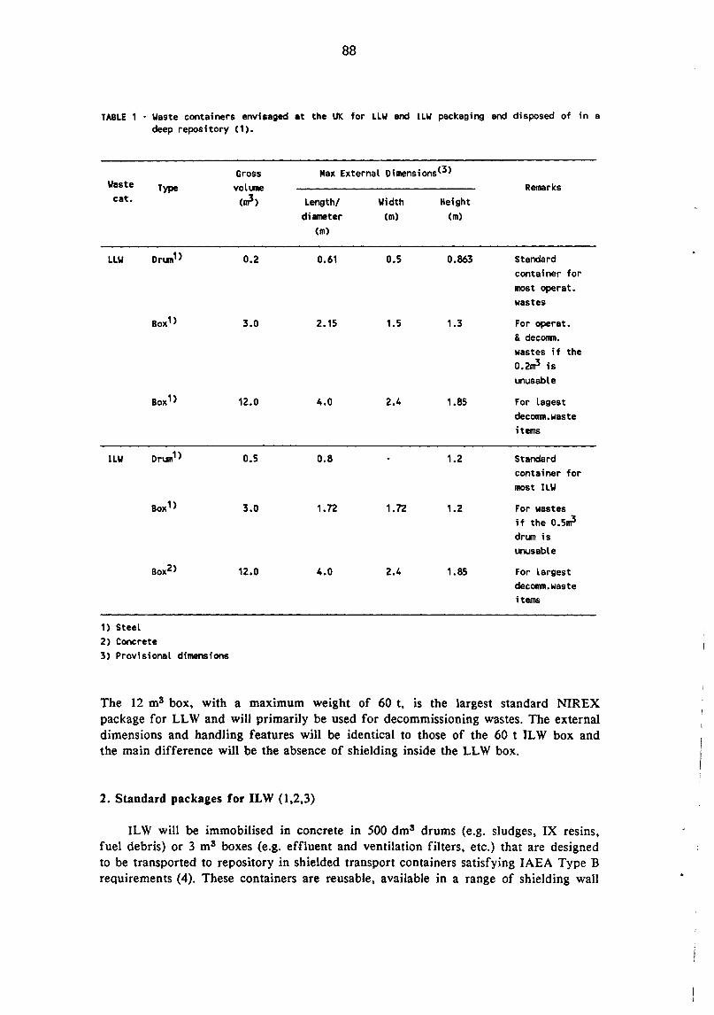
88
TABLE 1 • Waste containers envisaged at the UK for LLW and ILW packaging and disposed of in a deep repository (1).
Gross Max External Dimensions<3> Waste Type volune Remarks cat. cml> Length/ Width Height
diameter Cm) Cm> (m)
LLW Drun1 > 0.2 0.61 0.5 0.863 Standard container for most operat. wastes
Box1> 3.0 2.15 1.5 1.3 For operat. & dec011111. wastes if the 0.2ml is unusable
Box 1> 12.0 4.0 2.4 1.85 For lagest dec011111.waste items
ILW Drun1> 0.5 0.8 1.2 Standard container for most ILW
Box1> 3.0 1.72 1.72 1.2 For wastes if the 0.5ml drun is unusable
Box2> 12.0 4.0 2.4 1.85 For largest dec011111.waste items
1) Steel 2> Concrete 3) Provisional dimensions
The 12 m3 box, with a maximum weight of 60 t, is the largest standard NIREX package for LL W and wilJ primarily be used for decommissioning wastes. The external dimensions and handling features will be identical to those of the 60 t IL W box and the main difference will be the absence of shielding inside the LL W box.
2. Standard packages for ILW (1,2,3)
ILW will be immobilised in concrete in 500 dm3 drums (e.g. sludges, IX resins, fuel debris) or 3 m3 boxes (e.g. effluent and ventilation filters, etc.) that are designed to be transported to repository in shielded transport containers satisfying IAEA Type B requirements (4). These containers are reusable, available in a range of shielding wall

89
thicknesses between 70 mm and 280 mm of steel. As illustrated in Figs. 11.1 and 11.2 they will carry four 500 dm3 drums or one 3 m3 ILW box. The weight of the loaded transport container will range from about 20-60 t depending on the wall thickness (2). To demonstrate their capability to withstand (abnormal) conditions of transport, the 500 dms drum and a quarter scale model of the shielded transport container have been subjected to 9 m and 36 m drop tests. Fire (800°C) resistence tests have been also carried out (5).
Figure 11.1 ·Nirex ILW Transport Container. Figure 11.2 ·Nirex ILW Transport Container. Carrying Four 500 Litre Drums. Carrying a 3 ~ Box.
The 12 m3 box is a disposable self-shielding concrete container designed for packaging decommissioning wastes i.e. large bulky items or large amounts of waste that meet IAEA LSA III requirements (4). It differs from the other two ILW containers in that it incorporates its own shielding so that it is simultaneously a transport as well as a disposable package (2,3).
All IL W will be immobilised into the above three types of containers using cement grout or some other suitable matrix.
References
(1) Butterworth G.J., Radioactive Waste Management in the UK, Culham Fusion Report AEA FUS 68 (1990).
(2) Bennet D. et al., Radioactive Waste Transport to a NIREX Repository, Proc. of the Int. Conf. on Radioactive Waste Management 2, Brighton, May 2-5, 1989, BNES, London, Vol. 1, p. 45.
(3) Smith M.J.S. et al., Packaging of Radioactive Waste for Disposal in a Deep Repository, ibidem, Vol. 2, p. 85.

90
(4) Regulation for the Safe Transport of Ra(lioactive Wastes, IAEA Safety Series No 6, 1895 Edition, Supplement 1988 (1988).
(5) Ultgren A., National Conditions Pertaining to Radioactive Wastes in France, FRG, Sweden and UK STUDSVIK/NP-88/332 (1988).

91
Appendix III: CHARACTERISTICS AND DOSE RATE LIMITS OF PACKAGES TO BE USED FOR THE SHALLOW AND DEEP GEOLOGICAL DISPOSAL OF RADIOACTIVE WASTES IN SWEDEN.
1. Shallow geological repository (SFR) at Forsmark
TABLE 1 ·Standard packages for disposal of radioactive wastes into SFR at Forsmark (1,2)
External Dimensions Gross Maxi nun volLIIle weight
Waste est./Designation Length Diam/ Height width
(m) (m) (m) cml> (t)
LLW Steel dr1.111 0.6 0.9 0.2 Steel box 1.1 0.7 1.0 0.7 Steel box 1.4 1.1 1.0 1.4 Steel box 1.4 1.0 2.8
Container 3.0 2.4 2.6 15.5 25t Container 6.0 2.4 2.6 32 all Container 6.0 2.4 1.3 15.5
MLW Stell dr1.111 0.6 0.9 0.2 5 t per
4 dr1.111s
Concrete container (10 em wall) 1.2 1.2 1.2 1.0 5
Concrete container (25 em wall) 1.2 1.2 1.2 0.4 5
Concrete container with dri.IIIS 1.2 1.2 1.2 < 0.4 5
Steel container 1.2 1.2 1.2 1.6 5
Concrete tank 3.3 1.3 2.1 7 25
Steel container type B for 200 ~ drum 1.1 1.6 0.2 7
Drums and boxes containing LL W are placed before to be transported or disposed of into one of the container types listed in Table 1. No extra shielding is used for LL W packages. ML W packages are transported in a reusable shielding and remotely handled in the repository. Maximum weights are listed for types of packagings normally handled in the repository, i.e. max 25 t for LL W and 5 t for ML W packages. For unshielded LL W packages the maximum permissible surface dose rate is fixed by the transportation limit which must not exceed 2mSv• h-1 (200mr• h-1).

92
In case of ML W disposal the repository is dimensioned to handle packages having surface dose rates up to 500 mSv·h-1 (50 rem·h-1). The heat generation in the SFR from wastes is not a problem because of the limited activity inventory in the repository (1 ).
2. Deep geological repository (SFL)
TABLE 2 ·Standard packages envisaged for disposal of spent fuels, core c~ents and other
radioactive wastes into the future SFL (1,3).
External Dimensions Gross Maxi nun
Waste type/Designation Length Diam/ ·Height volume weight
width (m) em> Cm> cml> (t)
Spent fuel (SFL 2> To the reeesitor~: B·flask TN17/Mk2 6.2 1.95 3.1 76 containing: 17 BWR assembly 4.4 0.14 0.14 0.3 6·7 PWR assembly 4.1 0.214 0.214 0.65 zn the reegsitor~: Copper capsule 4.5 0.8 18.5·22 (for 2·2.3 t fuel>
Core components (SFL 5) To the reQQsitocx: B· flask TN17 or similar with cassette 4.6 0.8 0.8 2.9 -76 In the reeesitor~: Concrete blocks 5.3 1.25 1.25 5
React. operat. waste (SFL 3> Steel drum 0.6 0.9 0.2 Concrete container 1.2 1.2 1.2 1.0 Steel container type B for 200 dml 1.1 1.44 0.2
Decommissioning waste CSFL 4) Concrete container 2.4 2.4 2.4 8 Plus the same as for SFL 3
As indicated in Table 2 the Spent fuel and the core components will be transported in a type B flask to the conditioning facility at the respective repository (SFL 2 and 5) where appropriate packages for final disposal will be produced. The handling in the conditioning station and repository will be done under shielding and/or remotely controlled conditions, allowing high surface dose rates on the primary waste material.

93
Dose rate limits for LLW and MLW entering the repository (SFL 3 and 4) without conditioning will depend on the transportation system. The same limits as for SFR could be used as a preliminary assumption. The heat generation from spent fuels after 40 years of cooling is about 1 kW per ton of uranium. The spacing of tunnels and bore holes depends on the heat generation. For the other waste types the heat generation will be several orders of magnitude lower.
References
(1) Olsson G. and Hultgren A., Main Criteria and Parameters Related to the Disposal of NET Waste in German and Swidish Scenarios, STUDSVIK/NP-88/62 (1988).
(2) SKB - Swedish Nuclear Fuel and Waste Management Co. Repository for Reactor Waste. SFR Final Safety Report SFR-1, October 1987, quoted by ref. (1).
(3) SKB - Swedish Nuclear Fuel and Waste Management Co. Nuclear Power Back End Stage. Plan 86 Costs for the waste products from nuclear power generation. June 1986, quoted by ref. (1).


95
Appendix IV : PACKAGING METHODS AND TRANSPORT CONTAINERS PRESENTLY AVAILABLE IN THE US FOR TRITIUM SHIPPING PURPOSES.
Tritium containers presently applied in the U.S. for shipping purposes are listed in Table I derived from ref. (I).
Any container used for tritium transportation must be either DOE certified (ref. Directory of DOE Certificates of Compliance) or DOE/NRC certified. Current United States Department of Transportation regulations allow transport of gaseous tritium as air freight in DOT approved 12 dm3 (LP-12) and 50 dm3 (LP-50) containers at a maximum pressure of 113 kPa (850 torr) and 160 kPa (1200 torr) at 25°C, respectively.
The LP-12 container (see Table I) is a package for handling and transporting medium quantities of tritium. It is a nominal 12 litres, 347 stainless steel vessel with a 1.57 mm wall thickness and fitted with a stainless steel vacuum valve assembly. It is secured within a closed and sealed aluminum bucket with 0.25 m O.D., 0.51 m high, and a minimum wall thickness of 4.76 mm. The aluminum bucket is centered and supported within a 18-gauge, 0.49 m O.D. by 0.76 m high steel drum using celotex insulation. The shipping drum is secured by use of a bolted locking ring. The maximum tritium activity allowable in it for shipping purposes is of 1.2 PBq (-3.3xl04 Ci or 3.3 grams of tritium).
The LP-50 is a package for large quantities of tritium. Its construction closely parallels the LP-12 construction taking into account the larger capacity of the LP-50. The maximum tritium activity allowable in it for shipping purposes is of 7.16 PBq (-1.94xl05 Ci or 19.4 grams of tritium). Both these containers are currently used by the Savannah River Plant for transporting tritiated gas in the United States. Note that Savannah River is the only DOE-owned tritium production facility in the U.S. Their safe performances are well documented and many of such containers are presently available in the U.S.
A tritiated gas can also be be transported on depleted uranium beds as UT 3 and then it is a handled as if it was a tritiated solid waste. ORNL has designed a getter bed container which uses 250 g of depleted U-238 as getter material. The usable inside dimensions of the inner getter bed container are approximately 0.11 m ID by 0.25 m high. The assembly is made of 316 stainless steel. The overpack is an outer drum having a 16-gauge locking ring with a 7.94 mm diameter bolt and consists of a nominal 10-gal (-38 dm3) metal drum 0.38 m OD by 0.46 m high. Celotex rings are used to fill the annular interspace between the walls of two drums. The maximum tritium activity allowable in such a container for shipping purposes is of 1.85 PBq (5xl04Ci or 5 grams of tritium).
Tritiated water destined to be reprocessed can be transported in DOT approved containers after it has been solidified by adsorption on a molecular sieve bed. Tritiated water to be disposed of as a waste may be solidified by sorption on molecular sieves (e.g. TST A) or by a dry cement mix hydration (e.g. Mound Plant). Tritiated composites are then shipped to the reprocessing facility or disposal site into a DOT specification

TABLE 1 • Packages presently used at some U.S. laboratories for safe transportation of tritiated gases for reprocessing or tritiated solid wastes for disposal.
Container External Dimensions(m) Usefull OVerpack Gross Shipped type Volume Dimens.(m) weight Material or Remarks Ref.
Lenght Diam or width Height (dnh Oiam. Height (Kg) Matrix
LP·'t2 0.24 0.28 12 0.49 0.76 59 Pure gas DOT approv. SRP ss vessel for medium tritium shipments (3.39 g.T max>
LP·50 n.a. n.a. 50 n.a. n.a. 11& Exhausted DOT approv. S1W ss vessel for Tritiated large tritium shipment Gas (19.49 g. T max)
U·getter 0.106 0.25 2.2 0.38 0.46 27.2 250g. of DOT approv. ORNl depteted ss container U·238 tritide (5 g. T 1118lt)
Al·MI·5 n.a. n.a. n.a. n.a. n.a. HTO on For shipment to a MS 1 1.0 Molecular regeneration facility ~
Sieves (10 g.T max)
Standard 55·gal 210 none if certified Tritiated DOT specification 17 H or 17 C Steel 1.2, 3 steel drum for type B shipment solid drums,certified for type A or B
wastes shipments used at TSTA & Mound
N·55 overpack (*) n.a. Packaged For being used as a type B shipment tritiated container solid wastes
Strong· tight (*) none var. Wipes, shoe, Standard DOT 17 H steel drums & boxes covers,paper drums or wooden boxes for
products and LSA solid waste shipments other LSA to burial ground solid wastes
(*) Standard dimensions for steel drums, 1.2x1.3x2.2 m for wooden boxes. n.a. =not available.

97
17 H or 17 C 55-gal steel drum. Depending on tritium content the outer drum must be qualified for type A orB shipment or transported inside a N-55 overpack (see Tab. I). Type A packages (~ 103 Ci of tritium per package) must withstand normal conditions of transport (see Tab. I 0, footnote 6) while type B packages (2:. I 03 Ci of tritium per package) must survive normal as well as moderately severe accidental conditions (see Tab. 10, footnote 7). Tritiated molecular sieves or hydrated cement are contained in a standard 90 mil (-2.3 mm) or a high density 40 mil (-Imm) polyethylene liner. The liner is placed in a 30-gal ( -115 dm3) DOT specification 17 H or 17 C steel drum which is asphalt lined. The 30-gal drum is then inserted in a 17 H or 17 C asphalt lined 55-gal (-210 dm3) steel drum, the annular void between the two concentric drums being filled with asphalt or vermiculite (see Tab. 9 footnote 8). The container developed and applied at Mound since several years for packaging disposable solidified tritiated liquids also met the DOT requirements for solid wastes (3) but the limited number of such containers presently available will be insufficient for packaging and shipment of solidified tritiated waste water from new fusion facilities (I).
References
(I) Gruetzmacher K.M. et al., Transportation of Tritiated Waste from Fusion Facilities, Proc. of 3rd CNS Topical Meeting on Tritium Technology in Fission, Fusion and Isotopic Applications, Toronto, Can., May 1-6, 1988, Fusion Technology, 14 (I 988) 966.
(2) Mershad E.A. et al., Packaging of Tritium-Contaminated Liquid Waste, Nucl. Tech. Vol. 32, (I 977) 53.
(3) Rogers M.L., Treatment and Disposal of Tritium Containing Waste at Mound, paper presented at the Am. Chern. Soc. Annual Meeting, Denver, April 5-l 0, 1987.


99
ABBREVIATIONS AND ACRONYMES
ACS
AECL
AGHS
ANORA
BfS
BNFL
BNPD
BVS
CANDU
CEA
CEC
CEGB
CEN
CIT
CLAB
CSM
DAM
DOE
DOE
DOT
DTRF
EEC
ERS
GDS
GPS
GWT
HOPE
HGW
HLW
HMPI
ILW
ITER
Air Clean-up System.
Atomic Energy of Canada Ltd.
Active Gas Handling System.
Agence National pour Ia gestion de Dechets RAdioactifs.
Bundesamt fi.ir Strithlenschutz (FRG), the Federal Office for Radiation Protection.
British Nuclear Fuel Limited (UK).
Bruce Nuclear Power Development (Ontario Hydro, CAN.).
Building Ventilation System.
CANadian Deuterium Uranium reactors (Ontario, Quebec, New Brunswick, 0 H).
Commission Energy Atomique (F).
Commission of European Communities.
Central Electricity Generating Board (UK).
Centre d'Etude Nucleaire (F).
Compact Ignition Tokamak (Princeton, NJ).
Swedish Central Intermediate Storage Facility for Spent Nuclear Fuels.
Centre de Stockage de Ia Manche (La Hague, F).
Division Application Militaires (F).
Department of the Environment (UK).
Department of Energy (USA).
Department of Transportation (USA).
Darlington Tritium Recovery Facility (Ontario Hydro, CAN).
European Economic Communities.
Effluent Removal System.
Gas Detritiation System.
Gas Purification System.
Gaseous Waste Treatment.
High Density Poly-Ethylene.
Heat Generating Waste.
High Level Waste.
Her Majesty Inspectorate of Pollution (UK).
Intermediate Level Waste.
International Thermonuclear Experimental Reactor.

JET
LANL
LLSB
LLW
LSA
LWPF
MLM
MP
MLW
MS
NEA
NET
NGS
NIREX
NPS
NRC
OECD
PHW
PPPL
PTB
RH
RWOS
SFL
SFR
SKB
SKI
SKN
SLL
SSGB
SSI
SWD
TEP
TFTR
100
Joint European Torus (EEC). Abingdon (UK).
Los Alamos National Laboratory (NM).
Low Level waste Storage Building (R WOS).
Low Level Waste.
Low Specific Activity.
Liquid Waste Packaging Facility (MP).
Mound Laboratory of Monsanto Research Corporation (now MP). Miaimisburg (Ohio).
Mound Plant Miamisburg (Ohio) operated by EG&G, formerly MLM.
Medium Level Waste.
Molecular Sieves.
Nuclear Energy Agency (OECD).
Next European Torus. the European Community Project aimed at constructing a thermonuclear experimental power reactor of the Tokamak type.
Nuclear Generating Station (CAN).
Nuclear Industry Radwaste EXecutive (UK).
Nuclear Power Station.
Nuclear Regulatory Commission (USA).
Organisation for Economic Co-operation & Development.
Pressurized Heavy Water (reactor).
Princeton Plasma Physic Laboratory (NJ).
Physikalisch Technische Bundesanstalt (FRG). the German Agency for construction and operation of radwaste repositories (now BfS).
Remote Handling (equipment).
Radioactive Waste Operation Site (BNPD).
Swedish Centralized Deep Geological Waste Repository.
Swedish Centralized Shallow Geological Waste Repository (Forsmark).
Swedish Nuclear Fuel & Waste Management Company.
Swedish Nuclear Fuel Inspectorate.
Swedish National Board for Spent Nuclear Fuel.
Sandia Livermore Laboratories (Calif.).
South Scotland Generating Board (UK).
Swedish National Institute for Radiation Protection.
Solid Waste Disposal system (TSTA).
Tritium Extraction Plant (Chalk River, AECL, CAN).
Tokamak Fusion Testing Reactor, Princeton (NJ).

TLK
TRF
TRL
TSTA
TWT
UKAEA
VLLW
VERS
VRF
WVRF
101
Tritium Laboratory Karlsruhe (FRG ).
Tritium Recovery Facility (Darlington, Ontario Hydro, CAN.).
Sandia Tritium Research Laboratory, Livermore (Calif.).
Tritium System Testing Assembly, Los Alamos (NM).
Tritium gaseous Waste Treatment system (TSTA).
United Kingdom Atomic Energy Authority.
Very Low Level Waste.
Vacuum Effluent Recovery System (TRL).
Volume Reduction Factor.
Waste Volume Reduction Facility (RWOS).


I
103
GLOSSARY
Terms that appear to be identified or explained sufficiently in the text are not included.
Composite
Conditioning
Container
Deep geological disposal
Disposal
Encapsulation
Encapsulating agent (or matrix or medium)
Filling material
The solid mixture of the incorporated waste form and the immobilisation matrix.
Those operations that transform wastes into forms suitable for transportation and/or storage and/or disposal. They usually include conversion of waste to more stable forms by radioactivity immobilisation, containerisation, and additional packaging.
The outer shell of package into which waste is placed.
Permanent confinement of radwaste packages into the mined cavities (e.g. vaults, silos, tunnels, boreholes, etc.) of a repository located in a deep geological formation. The emplacement of waste packages is usually carried out by a remotely operated equipment. As the waste emplacement proceeds, concrete grout is successively added for sealing the packages into the cavity (silos, boreholes) or more simply to cover waste packages for stabilisation purposes (tunnels).
Permanent confinement of radioactive wastes under safe conditions in order to keep them isolated from mankind and his environs. No retrieval is envisaged so that it is defined as "ultimate or final". Confinement concepts include: - emplacement in shallow sub-surface engineered
structures; - emplacement in deep geological formations; - emplacement on, into or beneath the sea-bed.
The operation involving the emplacement of the solid or solidified radwaste into an encapsulating matrix to form a solid composite. See also immobilisation.
A hardening material such as concrete or cement-based grout, asphalt, polymers, etc. having the capability of immobilising the solid radwaste so that a solid composite incorporating the solid waste item and its contaminant radionuclides is formed.
A free-flowing material (e.g. concrete grout, or absorbers, or asphalt) that is used to fill the void space within a package or between stacked packages.

Geological formation
Interim (or intermediate) storage
lmmobilisation
lmmobilisation agent (or matrix, or medium)
Package
Packaging
Permanent or final storage
Pre-treatmellt
Repository
Retrievabi lity
Sea disposal
Sea dumping
104
Persistent bodies of igneous, metamorphic or sedimentary rocks, lying within a continental environment, being isolated from the biosphere and considered as potential host media for ultimate disposal of radioactive waste. Distinguished from other concepts focussed on marine environment, such as, for instance, the sediments of ocean abyssal plains.
Storage operations of temporary nature entailing the possibility of waste retrieval. They involve: - monitoring and surveillance;
subsequent waste handling operations including treatments, transportation and eventually final disposal.
The operation involving either the solidification of liquid or fluid radwastes or the encapsulation of solid radwastes by an immobilisation matrix in order to prevent their dispersion in the environment, in case of an accidental breaching of the waste containment package.
A solid material that is used for solidifying liquid and encapsulating solid radwastes. More specifically these materials are defined as solidifying and encapsulating media.
The assembly of the container(s), the conditioned radioactive waste, along with the filling material (if required) and the closure cap.
The act of manufacturing a package.
Storage operations for which it may be anticipated: - no expectation of subsequent waste treatment and
transportation (no waste retrieval after emplacement); - possible conversion to ultimate disposal.
Those operations that modify the original waste conditions and characteristics for economy and safety reasons. They usually include waste sorting and volume reduction and often a partial waste decontamination.
A location containing wastes in storage or disposal.
The specific condition of some waste packages that may be removed from its interim storage location.
Confinement of a radwaste material into the sea, such as by dumping.
Any deliberate disposal at sea of radwastes from vessels, aircraft, platforms or other man-made structures at sea. •
..
•
I
Shallow land (or ground) disposal (or burial)
Solidification
Solidifying agent (or matrix, or medium)
Surface storage or disposal
Under sea bed disposal
105
Permanent confinement of radwaste packages into subsurface engineered facilities (e.g. reinforced concrete lined trenches) where a backfilling material is poured between packages. It is synonymous with near surface disposal and shallow subsurface disposal.
The operation aimed at processing a liquid or fluid radwaste to immobilise and convert it to a dry stable solid. See also immobilisation .
A solid material such as cement powder, dryers, absorbers, etc., having the capability of solidifying liquid or gaseous radwastes by hydration or sorption phenomena, so that a solid composite incorporating the contaminant radionuclides is formed.
Confinement of radwaste packages on specially prepared drained areas that enable to keep them out from the soil contact (e.g. concrete platforms, asphalt pads, etc.). Packages are stacked on these areas in successive layers, protected against rain water with a thick layer of impermeable clay or plastic covers and then covered by forming soil (e.g. tumulus). It can be retrievable (storage) or permanent (disposal). In the latter case a backfilling material is poured between packages.
Permanent confinement of radwastes in tunnels located beneath the sea-bed with access from the shore .

106
For up-to-date information on European Community research
tllllll
I 1111111 CORDIS
consult
CORDIS The Community Research
and Development Information Service
CORDIS is an on-line service set up under the VALUE programme to give quick and easy access to information on European Community research programmes.
The CORDIS service is at present offered free-of-charge by the European Commission Host Organisation (ECHO). A menu-based interface makes CORDIS simple to use even if you are not familiar with on-line information services. For experienced users, the standard Common Command Language (CCL) method of extracting data is also available.
CORDIS comprises eight databases:
RTD-News: short announcements of Calls for Proposals, publications and events in the R&D field
RTD-Programmes: details of all EC programmes in R&D and related areas
RTD-Projects: containing 14,000 entries on individual activities within the programmes
RTD-Publications: bibliographic details and summaries of more than 50,000 scientific and technical publications arising from EC activities
RTD-Results: provides valuable leads and hot tips on prototypes ready for industrial exploitation and areas of research ripe for collaboration
RTD-Comdocuments: details of Commission communications to the Council of Ministers and the European Parliament on research topics
RTD-Acronyms: explains the thousands of acronyms and abbreviations current in the Community research area
RTD-Partners: helps bring organisations and research centres together for collaboration on project proposals, exploitation of results, or marketing agreements.
~ ~ For more information and CORDIS registration forms, contact
ECHO Customer Service CORDIS Operations
BP 2373 L-1 023 Luxembourg
Tel.: (+352) 34 98 11 Fax: (+352) 34 9812 34
' If you are already an ECHO user, please indicate your customer number.
.. '
•
•

