commodore 64 programmers reference · pdf filegraphics overview all of the graphics abilities...
TRANSCRIPT
GRAPHICS OVERVIEW
All of the graphics abilities of the Commodore 64 come from the 6567Video Interface Chip (also known as the VIC-II chip). This chip gives avariety of graphics modes, including a 40 column by 25 line text display,a 320 by 200 dot high resolution display, and SPRITES, small movableobjects which make writing games simple. And if this weren't enough,many of the graphics modes can be mixed on the same screen. It ispossible, for example, to define the top half of the screen to be in highresolution mode, while the bottom half is in text mode. And SPRITESwillcombine with anything! More on sprites later. First the other graphicsmodes.
The VIC-II chip has the following graphics display modes:
A) CHARACTER DISPLAYMODES
1) Standard Character Modea) ROM charactersb) RAM programmable characters
2) Multi-Color Character Modea) ROM charactersb) RAM programmable characters
3) Extended Background Color Modea) ROM charactersb) RAM programmable characters
B) BIT MAP MODES
1) Standard Bit Map Mode2) Multi-Color Bit Map Mode
C) SPRITES
1) Standard Sprites2) Multi-Color Sprites
100 PROGRAMMING GRAPHICS
GRAPHICS LOCATIONS
Some general information first. There are 1000 possible locations onthe Commodore 64 screen. Normally, the screen starts at location 1024($0400 in HEXadecimal notation) and goes to location 2023. Each ofthese locations is 8 bits wide. This means that it can hold any integernumber from 0 to 255. Connected with screen memory is a group of1000 locations called COLOR MEMORY or COLOR RAM. These start at
location 55296 ($D800 in HEX) and go up to 56295. Each of the colorRAM locations is 4 bits wide, which means that it can hold any integernumber from 0 to 15. Since there are 16 possible colors that the Com-modore 64 can use, this works out well.
In addition, there are 256 different characters that can be displayed
at any time. For normal screen display, each of the 1000 locations inscreen memory contains a code number which tells the VIC-II chip whichcharacter to display at that screen location.
The various graphics modes are selected by the 47 CONTROL regis-ters in the VIC-II chip. Many of the graphics functions can be controlledby POKEing the correct value into one of the registers. The VIC-II dhip islocated starting at 53248 ($DOOOin HEX)through 53294 ($D02E in HEX).
VIDEO BANK SELECTION
The VIC-II chip can access ("see") 16K of memory at a time. Sincethere is 64K of memory in the Commodore 64, you want to be able tohave the VIC-II chip see all of it. There is a way. There are 4 possibleBANKS (or sections) of 16K of memory. All that is needed is some meansof controlling which 16K bank the VIC-II chip looks at. In that way, thechip can "see" the entire 64K of memory. The BANKSELECT bits thatallow you access to all the different sections of memory are located inthe 6526 COMPLEX INTERFACEADAPTERCHIP #2 (CIA #2). The POKEand PEEK BASIC statements (or their machine language versions) areused to select a bank by controlling bits 0 and 1 of PORT A of CIA#2(location 56576 (or $DDOOHEX». These 2 bits must be set to outputs bysetting bits 0 and 1 of location 56578 ($DD02.HEX) to change banks. Thefollowing example shows this:
POKE 56578,PEEK(56578)OR 3 :REM MAKE SURE BITS 0 AND 1 ARESET TO OUTPUTSPOKE 56576,(PEEK(56576)AND 252)OR A:REM CHANGE BANKS
"A" should have one of the following values:
PROGRAMMING GRAPHICS 101
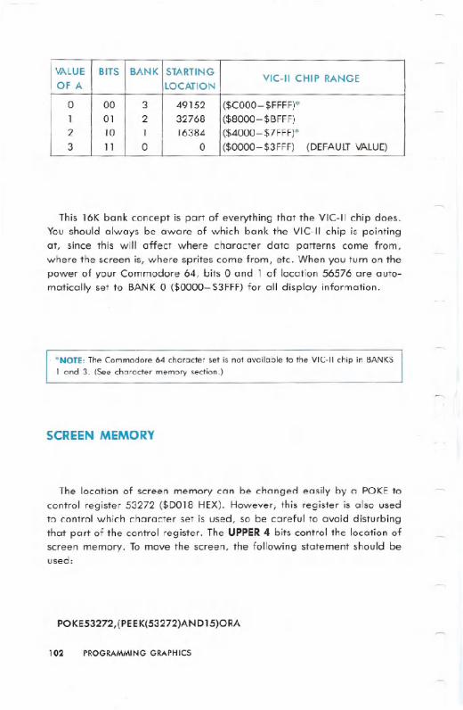
This 16K bank concept is part of everything that the VIC-II chip does.You should always be aware of which bank the VIC-II chip is pointing
at, since this will affect where character data patterns come from,
where the screen is, where sprites come from, etc. When you turn on the
power of your Commodore 64, bits 0 and 1 of location 56576 are auto-matically set to BANK 0 ($0000-$3FFF) for all display information.
.NOTE: The Commodore 64 character set is not available to the VIC-II chip in BANKS
1 and 3. (See character memory section.)
SCREEN MEMORY
The location of screen memory can be changed easily by a POKE to
control register 53272 ($DOI8 HEX). However, this register is also used
to control which character set is used, so be careful to avoid disturbing
that part of the control register. The UPPER 4 bits control the location of
screen memory. To move the screen, the following statement should beused:
POKE53272,(PEEK(53272)AND15)ORA
102 PROGRAMMING GRAPHICS
VALUE BITS BANK STARTINGVIC-II CHIP RANGE
OF A LOCATION
0 00 3 49152 ($COOO-$FFFF)*1 01 2 32768 ($8000-$BFFF)2 10 1 16384 ($4000- $7FFF)*3 11 0 0 ($0000-$3FFF) (DEFAULT VALUE)
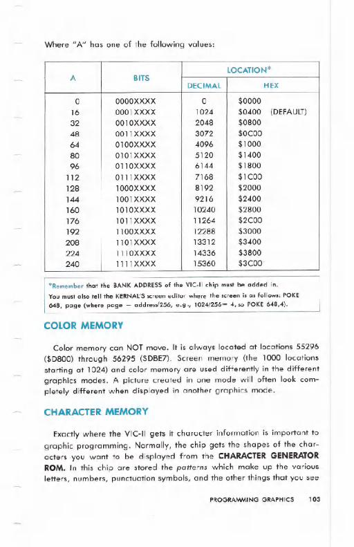
Where" A" has one of the following values:
'Remember that the BANK ADDRESS of the VIC-II chip must be added in.
You must also tell the KERNAL'Sscreen editor where the screen is as follows: POKE
648, page (where page = address/256, e.g., 1024/256= 4, so POKE 648,4).
COLOR MEMORY
Color memory can NOTmove. It is always located at locations 55296($D800) through 56295 ($DBE7). Screen memory (the 1000 locationsstarting at 1024) and color memory are used differently in the differentgraphics modes. A picture created in one mode will often look com-pletely different when displayed in another graphics mode.
CHARACTER MEMORY
Exactly where the VIC-II gets it character information is important tographic programming. Normally, the chip gets the shapes of the char-acters you want to be displayed from the CHARACTERGENERATORROM. In this chip are stored the patterns which make up the variousletters, numbers, punctuation symbols, and the other things that you see
PROGRAMMING GRAPHICS 103
LOCATION*A BITS
DECIMAL HEX
0 OOOOXXXX 0 $000016 0001 XXXX 1024 $0400 (DEFAULT)
32 0010XXXX 2048 $080048 0011XXXX 3072 $OCOO64 0100XXXX 4096 $100080 0101XXXX 5120 $140096 0110XXXX 6144 $1800
112 0111XXXX 7168 $lCOO128 1000XXXX 8192 $2000144 1001XXXX 9216 $2400160 1010XXXX 10240 $2800176 1011XXXX 11264 $2COO192 1100XXXX 12288 $3000208 1101XXXX 13312 $3400224 1110XXXX 14336 $3800240 1111 XXXX 15360 $3COO.

on the keyboard. One of the features of the Commodore 64 is the abilityto use patterns located in RAM memory. These RAM patterns arecreated by you, and that means that you can have an almost infinite setof symbols for" games, business applications, etc.
A normal character set contains 256 characters in which each c.har-acter is defined by 8 bytes of data. Since each character takes up 8bytes this means that a full character set is 256*8=2K bytes of memory.Since the VIC-II chip looks at 16K of memory at a time, there are 8possible locations for a complete character set. Naturally, you are freeto use less than a full character set. However, it must still start at one ofthe 8 possible starting locations.
The location of character memory is controlled by 3 bits of the VIC-IIcontrol register located at 53272 ($DOI8 in HEX notation). Bits 3,2, and1 control where the characters' set is located in 2K blocks. Bit 0 is ig-nored. Remember that this is the same register that deterrt.ines wherescreen memory is located so avoid disturbing the screen memory bits. Tochange the location of character me{T1ory,the following BASIC state-ment can be used:
POKE 53272,(PEEK(53272)AND240)OR A
Where A is one of the following values:
'Remember to add in the BANKaddress.
104 PROGRAMMING GRAPHICS
VALUEI
LOCATION OF CHARACTER MEMORY*BITS
of A DECIMAL HEX
0 XXXXOOOX 0 $0000-$07FF2 XXXXOOIX 2048 $0800-$OFFF
4 XXXXOI0X 4096 $1000-$17FF ROM IMAGE in BANK
o & 2 (default)6 XXXXOIIX 6144 $1800-$1 FFF ROM IMAGE in BANK
0&2
8 XXXX 1 OOX 8192 $2000-$27FF10 XXXXI0IX 10240 $2800-$2FFF12 XXXXII0X 12288 $3000-$37FF14 XXXXIIIX 14336 $3800-$3FFF

The ROM IMAGE in the above table refers to the character generator
ROM. It appears in place of RAM at the above locations in bank O. It
also appears in the corresponding RAM at locations 36864-40959($9000-$9FFF) in bank 2. Since the VIC-II chip can only access 16K of
memory at a time, the ROM character patterns appear in the 16K block
of memory the VIC-II chip looks at. Therefore, the system was designed
to make the VIC-II chip think that the ROM characters are at 4096-8191($1000-$1 FFF) when your data is in bank 0, and 36864-40959
($9000-$9FFF) when your data is in bank 2, even though the character
ROM is actually at location 53248-57343 ($DOOO-$DFFF). This imaging
only applies to character data as seen by the VIC-II chip. It can be used
for programs, other data, etc., just like any other RAM memory.
NOTE: If these ROM images get in the way of your own graphics, then set the BANKSELECT BITS to one of the BANKS without the images (BANKS 1 or 3). The ROM
patterns won't be there.
The location and contents of the character set in ROM are as follows:
Sharp-eyed readers will have just noticed something. The locationsoccupied by the character ROM are the same as the ones occupied bythe VIC-II chip control registers. This is possible because they don't oc-cupy the same locations at the same time. When the VIC-II chip needs to
PROGRAMMINGGRAPHICS 105
ADDRESS VIC-II CONTENTSBLOCK DECIMAL HEX IMAGE
0 53248 DOOO- D1FF 1000- 11FF Upper case characters53760 D200- D3FF 1200-13FF Graphics characters
54272 D400- D5FF 1400-15FF Reversed upper casecharacters
54784 D600- D7FF 1600- 17FF Reversed graphicscharacters
1 55296 D800- D9FF 1800- 19FF Lower case characters
55808 DAOO- DBFF 1AOO- 1BFF Upper case & graphicscharacters
56320 DCOO- DDFF 1COO- 1DFF Reversed lower casecharacters
56832 DEOO-DFFF 1EOO- 1FFF Reversed upper case &graphics characters

access character data the ROM is switched in. It becomes an image inthe 16K bank of memory that the VIC-II chip is looking at. Otherwise,the area is occupied by the I/O control registers, and the character ROMis only available to the VIC-II chip.
However, you may need to get to the character ROM if you are goingto use programmable characters and want to copy some of the char-acter ROM for some of your character definitions. In this case you mustswitch out the I/O register, switch in the character ROM, and do yourcopying. When you're finished, you must switch the I/O registers back inagain. During the copying process (when I/O is switched out) no inter-rupts can be allowed to take place. This is because the I/O registers areneeded to service the interrupts. If you forget and perform an interrupt,really strange things happen. The keyboard should not be read duringthe copying process. To turn off the keyboard and other normal inter-rupts that occur with your Commodore 64, the following POKE should beused:
POKE 56334,PEEK(56334)AND254 (TURNS INTERRUPTS OFF)
After you are finished getting characters from the character ROM,and are ready to continue with your program, you must turn thekeyboard scan back on by the following POKE:
POKE 56334,PEEK(56334)ORI (TURNS INTERRUPTS ON)
The following POKE will switch out I/O and switch the CHARACTERROM in:
POKE l,PEEK(1)AND251
The character ROM is now in the locations from 53248-57343 ($DOOO-
$DFFF).To switch I/O back into $DOOOfor normal operation use the following
POKE:
POKE l,PEEK(l)OR 4
106 PROGRAMMING GRAPHICS
STANDARD CHARACTER MODE
Standard character mode is the mode the Commodore 64 is in when
you first turn it on. It is the mode you will generally program in.Characters can be taken from ROM or from RAM, but normally they
are taken from ROM. When you want special graphics characters for aprogram, all you have to do is define the new character shapes in RAM,and tell the VIC-II chip to get its character information from there in-stead of the character ROM. This is covered in more detail in the nextsection.
In order to display characters on the screen in color, the VIC-II chipaccesses the screen memory to determine the character code for thatlocation on the screen. At the same time, it accesses the color memoryto determine what color you want for the character displayed. Thecharacter code is translated by the VIC-II into the starting address of the8-byte block holding your character pattern. The 8-byte block is locatedin character memory.
The translation isn't too complicated, but a number of items are com-bined to generate the desired address. First the character code you useto POKE screen memory is multiplied by 8. Next add the start of char-acter memory (see CHARACTERMEMORYsection). Then the Bank SelectBits are taken into account by adding in the base address (see VIDEOBANK SELECTIONsection). Below is a simple formula to illustrate whathappens:
CHARACTER ADDRESS = SCREEN CODE*8+(CHARACTERS ET* 2048) + (BAN K* 16384)
CHARACTER DEFINITIONS
Each character is formed in an 8 by 8 grid of dots, where each dotmay be either on or off. The Commodore 64 character images arestored in the Character Generator ROM chip. The characters are storedas a set of 8 bytes for each character, with each byte representing the
dot pattern of a row in the character, and each bit representing a dot.A zero bit means that dot is off, and a one bit means the dot is on.
The character memory in ROM begins at location 53248 (when the I/Ois switched off). The first 8 bytes from location 53248 ($DOOO)to 53255($D007) contain the pattern for the @ sign, which has a character codevalue of zero in the screen memory. The next 8 bytes, from location
PROGRAMMINGGRAPHICS 107

53256 ($D008) to 53263 ($DOOF), contain the information for forming the
letter A.
Each complete character set takes up 2K (2048 bits) of memory, 8
bytes per character and 256 characters. Since there are two character
sets, one for upper case and graphics and the other with upper and
lower case, the character generator ROM takes up a total of 4K loca-
tions.
PROGRAMMABLE CHARACTERS
Since the characters are stored in ROM, it would seem that there is no
way to change them for customizing characters. However, the memory
location that tells the VIC-II chip where to find the characters is a pro-
grammable register which can be changed to point to many sections of
memory. By changing the character memory pointer to point to RAM,
the character set may be programmed for any need.
If you want your character set to be located in RAM, there are a few
VERY IMPORTANT things to take into account when you decide to actu-
ally program your own charadter sets. In addition, there are two other
important points you must know to create your own special characters:
1) Itisan allor nothing pr0gess. Generally, ifyou use your own char-
acter set by telling the Vlt-II chip to get the character information
from the area you have prepared in RAM, the standard Commo-
dore 64 characters are unavailable to you. To solve this, you must
copy any letters,numbers, or standard Commodore 64 graphics
you intend to use intoyour own character memory in RAM. You can
pick and choose, take only the ones you want, and don't even
have to keep them in order!
108 PROGRAMMING GRAPHICS
IMAGE BINARY PEEK** 00011000 24**** 00111100 60** **
011 0011 0 102****** 01111110 126** **
011 0011 0 102** ** 01100110 102** **
011 0011 0 102
00000000 0
2) Your character set takes memory space away from your BASICprogram. Of course, with 38K available for a BASIC program,most applications won't have problems.
WARNING: You must be careful to protect the character set from being overwritten
by your BASIC program, which also uses the RAM.
There are two locations in the Commodore 64 to start your characterset that should NOT be used with BASIC: location 0 and location2048. The first should not be used because the system stores importantdata on page O. The second can't be used because that is where yourBASIC program starts! However, there are 6 other starting positions foryour custom character set.
The best place to put your character set for use with BASIC whileexperimenting is beginning at 12288 ($3000 in HEX). This is done byPOKEing the low 4 bits of location 53272 with 12. Trythe POKE now, likethis:
POKE 53272,(PEEK(53272)AND240)+ 12
Immediately, all the letters on the screen turn to garbage, This isbecause there are no characters set up at location 12288 right now. . .only random bytes. Set the Commodore 64 back to normal by hittingthe .:mlr~'111111key and "then the .~j:l-'1(oI~j:llkey.
Now let's begin creating graphics characters. To protect your char-acter set from BASIC, you should reduce the amount of memory BASICthinks it has. The amount of memory in your computer stays thesame. . . it's just that you've told BASIC not to use some of it. Type:
PRINT FRE(O)-(SGN(FRE(O»<O)*65535
The number displayed is the amount of memory space left unused. Now
type the following:
POKE 52,48:POKE56,48:CLR
Now type:
PRINT FRE(O)-(SGN(FRE(O»<0)*65535
PROGRAMMINGGRAPHICS 109

See the change? BASIC now thinks it has less memory to work with. Thememory you just claimed from BASIC is where you are going to put yourcharacter set, safe from actions of BASIC.
The next step is to put your characters into RAM. When you begin,there is random data beginning at 12288 ($3000 HEX). You must putcharacter patterns in RAM (in the same style as the ones in ROM) for theVIC-II chip to use.
The following program moves 64 characters from ROM to your char-acter set RAM:
5 PRINTCHR$(142) :REMSWITCH TOUPPER CASE10 POKE52,48:POKE56,48:CLR :REM RESERVE MEMORYFOR CHARACTERS20 POKE56334, PEEK (56334) At.m254 :REt1 TURt.~OFFKEYSCAN INTERRUPTTIMER30 POKE1,PEEK(1)AND251 :REMSWITCH INCHARACTER4121 FOR I=0T0511 :POKE I+ 12288., PEEK ( 1+53248) : t~E:":T
50 POKE1,PEEK(1)OR4 :REM SWITCH IN I/O60 POKE56334,PEEK(56334)OR1 :REM RESTARTKEYSCAN INTERRUPT TIMER70 Et~D
Now POKE location 53272 with (PEEK(53272)AND240)+ 12. Nothinghappens, right? Well, almost nothing. The Commodore 64 is now gettingit's character information from your RAM, instead of from ROM. Butsince we copied the characters from ROM exactly, no difference can beseen. . . . yet.
You can easily change the characters now. Clear the screen and typean @ sign. Move the cursor down a couple of lines, then type:
FOR I = 12288 TO 12288+7:POKE I, 255 - PEEK(I): NEXT
You just created a reversed @ sign!
TIP: Reverse.d characters are just characters with their bit patterns in character memoryreversed.
Now move the cursor up to the program again and hit ...again to re-reverse the character (bring it back to. normal). By looking atthe table of screen display codes, you can figure out where in RAMeachcharacter is. Just remember that each character takes eight memorylocations to store. Here's a few examples just to get you started:
110 PROGRAMMING GRAPHICS

Remember that we only took the first 64 characters. Something else
will have to be done if you want one of the other characters.
What if you wanted character number 154, a reversed Z? Well, youcould make it yourself, by reversing a Z, or you could copy the set ofreversed characters from the ROM, or just take the one. character you
want from ROM and replace one of the characters you have in RAM that
you don't need.Suppose you decide that you won't need the> sign. Let's replace the
> sign with the reversed Z. Type this:
FOR 1=0 TO 7: POKE 12784 + I, 255-PEEK(I+12496): NEXT
Now type a > sign. It comes up as a reversed Z. No matter how
many times you type the>, it comes out as a reversed Z. (This changeis really an illusion. Though the> sign looks like a reversed Z, it still acts
like a >in a program. Try something that needs a > sign. It will still
work fine, only it will look strange.)
A quick review: You can now copy characters from ROM into RAM.You can even pick and choose only the ones you want. There's only one
step left in programmable characters (the best step!) . . . making yourown characters.
Remember how characters are stored in ROM? Each character is
stored as a group of eight bytes. The bit patterns of the bytes directlycontrol the character. If you arrange 8 bytes, one on top of another,and write out each byte as eight binary digits, it forms an eight by eightmatrix, looking like the characters. When a bit is a one, there is a dot atthat location. When a bit is a zero, there is a space at that location.
When creating your own characters, you set up the same kind of tableIn memory. Type NEWand then type this program:
10 FOR I = 12448 TO 12455 : READ A: POKE I,A: NEXT
20 DATA 60, 66, 165, 129, 165, 153, 66, 60
PROGRAMMING GRAPHICS 111
CHARACTER DISPLAYCODE CURRENTSTARTINGLOCATION IN RAM
@ 0 12288A 1 12296! 33 12552
> 62 12784
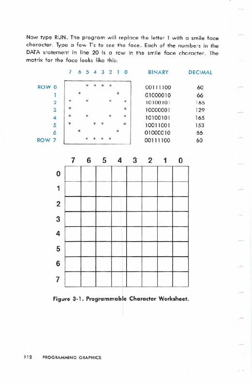
Now type RUN. The program will replace the letter T with a smile facecharacter. Type a few 1's to see the face. Each of the numbers in theDATA statement in line 20 is a row in the smile face character. Thematrix for the face looks like this:
1
7 6 5 4 2 1 oo
2
3
4
5
6
7
Figure 3-1. Programmable Character Worksheet.
112 PROGRAMMING GRAPHICS
7 65432 1 0 BINARY DECIMAL
ROW 0 * * * * 001111 00 601 * * 01000010 662 * * * * 10100101 1653 * * 10000001 1294 * * * * 10100101 1655 * * * * 10011001 1536 * * 01000010 66
ROW 7 * * * * 001111:00 60
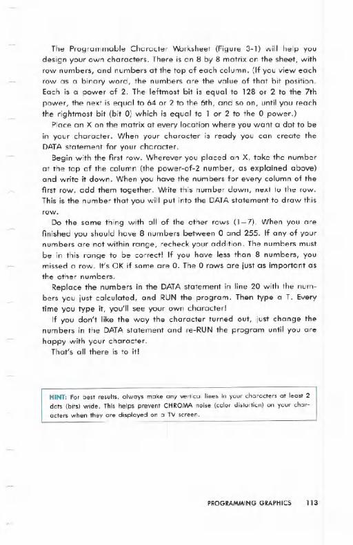
The Programmable Character Worksheet (Figure 3-1) will help youdesign your own characters. There is an 8 by 8 matrix on the sheet, withrow numbers, and numbers at the top of each column. (If you view eachrow as a binary word, the numbers are the value of that bit position.Each is a power of 2. The leftmost bit is equal to 128 or 2 to the 7thpower, the next is equal to 64 or 2 to the 6th, and so on, until you reachthe rightmost bit (bit 0) which is equal to 1 or 2 to the 0 power.)
Place an X on the matrix at every location where you want a dot to bein your character. When your character is ready you can create theDATAstatement for your character.
Begin with the first row. Wherever you placed an X, take the numberat the top of the column (the power-of-2 number, as explained above)and write it down. When you have the numbers for every column of thefirst row, add them together. Write this number down, next to the row.This is the number that you will put into the DATAstatement to draw thisrow.
Do the same thing with all of the other rows (I -7). When you are
finished you should have 8 numbers between 0 and 255. If any of yournumbers are not within range, recheck your addition. The numbers mustbe in this range to be correct! If you have less than 8 numbers, youmissed a row. It's OK if some are o. The 0 rows are just as important asthe other numbers.
Replace the numbers in the DATAstatement in line 20 with the num-bers you just calculated, and RUN the program. Then type a T. Everytime you type it, you'll see your own character!
If you don't like the way the character turned out, just change thenumbers in the DATAstatement and re-RUN the program until you are
happy with your character.That's all there is to it!
HINT: For best results, always make any vertical lines in your characters at least 2
dots (bits) wide. This helps prevent CHROMA noise (color distortion) on your char-
acters when they ore displayed on a TV screen.
PROGRAMMING GRAPHICS 113

Here is an example of a program using standard programmablecharacters:
10 REM* EXAMPLE1 *2121REM CREATING PROGRAMMABLE CHARACTERS31 POKE56334.PEEK(56334)AND254:POKE1,PEEK(I)AND251:REM TURN OFF KB AND 11035 FORI=0T063:REM CHARACTER RANGE TO BE COPIEDFROt1 ROM36 FORJ=0T07:REM COPY ALL 8 BYTES PER CHARACTER37 POKEI2288+I~8+J,PEEK(53248+I*8+J);REM COpy AB'r'TE38 NEXTJ:NEXTI:REM GOTO NEXT BYTE OR CHARACTER39 POKE1,PEEK(I)OR4:POKE56334,PEEK(56334)OR1;REMTURN ON 1/0 AND KB40 POKE532?2,(PEEK(53272)AND240)+12:REM SET CHARPOINTER TO MEM. 122886121FORCHAR=60TOG3:REM PROGRAM CHARACTERS 6121THRU 638121FORBYTE=I21TO?;REM DO ALL 8 BYTES OF A CHARACTER10121READ NUMBER:REM READ IN 1/8TH OF CHARACTER DATA12121POKE 12288+ (S*-CHAR)+B'r'TE.. NUMBER: REM STORE THEDATA I t.~ t1EMOR'T'14121 NEXTBYTE:NEXTCHAR;REM ALSO COULD BE NEXT BYTE,CHAR15121 PRINTCHR$(147)TAB(255)CHR$(60);155 PRINTCHR$(61)TAB(55)CHR$(62)CHR$(63)160 REM LINE 150 PUTS THE NEWLY DEFINED CHARACTERSOt~ THE SCREEN170 GETA$:REM WAIT FOR USER TO PRESS A KEY18121 I FA$=" "THE~~GOTO171.::1: REM I F ~m KE'r'S ~.jERE PRESSED,
TR'T' AGAIN!19121POKE53272,21:REM RETURN TO NORMAL CHARACTERS21210 DATA4.G,?,5,7,?3,3:REM DATA FOR CHARACTER 612121121 DATA 32,96,224, 16121,224,224,192,192;REM DATAFOR CHARACTER 6122121 DATA?,7,7.31,31,95, 143,127:REM DATA FORCHARACTER 6223121 DATA 224,224.224,248,248,248,24121,224:REM DATAFOR CHARACTER 63240 END
114 PROGRAMMING GRAPHICS
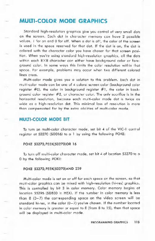
MULTI-COLOR MODE GRAPHICS
Standard high-resolution graphics give you control of very small dotson the screen. Each dot in character memory can have 2 possiblevalues, 1 for on and 0 for off. When a dot is off, the color of the screenis used in the space reserved for that dot. If the dot is on, the dot iscolored with the character color you have chosen for that screen posi-tion. When you're using standard high-resolution graphics, all the dotswithin each 8 X 8 character can either have background color or fore-ground color. In some ways this limits the color resolution within thatspace. For example, problems may occur when two different coloredlines cross.
Multi-color mode gives you a solution to this problem. Each dot inmulti-color mode can be one of 4 colors: screen color (background colorregister #0), the color in background register #1, the color in back-ground color register #2, or character color. The only sacrifice is in thehorizontal resolution, because each multi-color mode dot is twice aswide as a high-resolution dot. This minimal loss of resolution is morethan compensated for by the extra abilities of multi-color mode.
MULTI-COLOR MODE BIT
To turn on multi-color character mode, set bit 4 of the VIC-II control
register at 53270 ($D016) to a 1 by using the following POKE:
POKE 53270,PEEK(53270)OR 16
To turn off multi-color character mode, set bit 4 of location 53270 to a
o by the following POKE:
POKE 53270,PEEK(53270)AND 239
Multi-color mode is set on or off for each space on the screen, so thatmulti-color graphics can be mixed with high-resolution (hi-res) graphics.This is controlled by bit 3 in color memory. Color memory begins atlocation 55296 ($D800 in HEX). If the number in color memory is less
than 8 (0-7) the corresponding space on the video screen will bestandard hi-res, in the color (0-7) you've chosen. If the number locatedin color memory is greater or equal to 8 (from 8 to 15), then that spacewill be displayed in multi-color mode.
PROGRAMMINGGRAPHICS 115
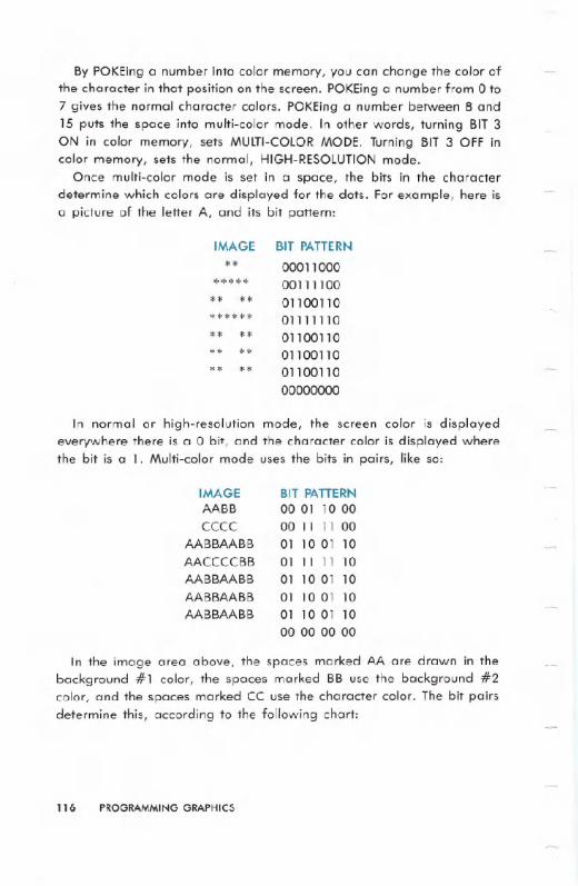
By POKEing a number into color memory, you can change the color ofthe character in that position on the screen. POKEing a number from 0 to7 gives the normal character colors. POKEing a number between 8 and15 puts the space into multi-color mode. In other words, turning BIT 3ON in color memory, sets MULTI-COLORMODE. Turning BIT 3 OFF incolor memory, sets the normal, HIGH-RESOLUTIONmode.
Once multi-color mode is set in a space, the bits in the characterdetermine which colors are displayed for the dots. For example, here isa picture of the letter A, and its bit pattern:
In normal or high-resolution mode, the screen color is displayedeverywhere there is a 0 bit, and the character color is displayed wherethe bit is a 1. Multi-color mode uses the bits in pairs, like so:
IMAGEAABB
CCCCAABBAABB
AACCCCBBAABBAABB
AABBAABBAABBAABB
BIT PATTERN
00 01 10 0000 11 11 0001 10 01 1001 11 11 1001 1001 1001 10 01 1001 10 01 1000 00 00 00
In the image area above, the spaces marked AA are drawn in thebackground #1 color, the spaces marked BB use the background #2color, and the spaces marked CC use the character color. The bit pairsdetermine this, according to the following chart;
116 PROGRAMMING GRAPHICS
IMAGE BIT PATTERN** 00011 000
***** 00111100** ** 0110011 0****** 01111110** ** 01100110** ** 011 00110** ** 011 0011 0
00000000

NOTE: The sprite foreground color is a 10. The character foreground color is a 11.
Type NEW and then type this demonstration program:
lee POKE53281,I:REM SET BACKGROUND COLOR i0 TO~IHITE110 POKE53282,3:REM SET BACKGROUND COLOR il TO CYAN1213 POKE53283,8:REM SET BACKGROUND COLOR i2 TOORANGE1313 POKE5327ehPEEK (53270) OR16 : REt1 TURr~ Ot~t'1ULTI COLOR t10DE1413 C=13*4096+8*256:REM SET C TO POINT TO COLORt1Et10RY1513 PRItHCHR$( 147) "AAAAAAAAAA"
.1613 FORL-=13T09179 POKEC+L,8:REM USE MULTI BLACK1813 t'~E;:n
The screen color is white, the character color is black, one color regis-ter is cyan (greenish blue), the other is orange.
You're not really putting color codes in the :space for character color,you're actually using references to the registers associated with thosecolors. This conserves memory, since 2 bits can be used to pick 16 colors(background) or 8 colors (character). This also 'makes some neat trickspossible. Simply changing one of the indirect registers will change everydot drawn in that color. Therefore everything drawn in the screen and
PROGRAMMINGGRAPHICS 117
BIT PAIR COLOR REGISTER LOCATION
00 Background #0 color (screen color) 53281 ($D021)01 Background #1 color 53282 ($D022)10 Background #2 color 53283 ($D023)11 Color specified by the color RAM
lower 3 bits in color memory

background colors can be changed on the whole screen instantly. Hereis an example of changing background color register #1:
10121 POKE53270.PEEK(5327e)OR16:REM TURN ON~IULTI COLOR t10DE110 PRINTCHR$(147)CHR$(18),
Aa12121PR I ~n" ;:t~"; : REM TYPE C= ~\ 1 FOR ORANGE ORMULTICOLOR BLACK BACKGROUND130 FORL=1T022: PRINTCHR$(65) ,: NEXT135 FORT=1T0500:NEXT
140 PRI ~n" =f.7~1;';~ TYPE CTRL .!\ 7 FOR BLUE COLORCHA~jGE145 FORT=1T0500:NEXT
~a150 PRINT"8HIT A KEY"1610 GETI'=!$:I FA$=" "THEN 160170 X=INT(RND(1)~16)18121 POKE 53282.X19121GOTO 160
By using the [I key and the COLOR keys the characters can bechanged to any color, including multi-color characters. For example,type this command:
POKE 53270,PEEK(53270)OR 16:PRINT " II ";: REM LT.RED/
MULTI-COLORRED t ~
~The word READY and anything else you type will be displayed in
multi-color mode. Another color control can set you back to regular text.
118 PROGRAMMING GRAPHICS
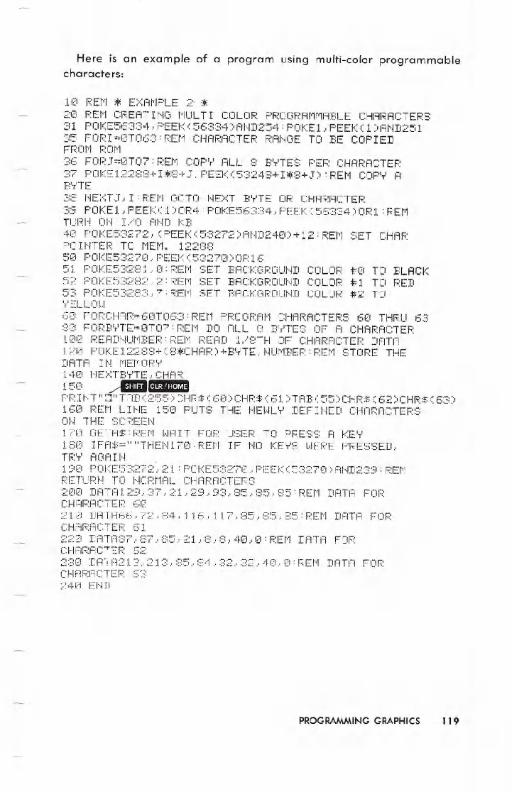
Here is an example of a program using multi-color programmablecharacters:
10 REM ~ EXAMPLE 2'~
2(1 REt1 CF.:EAT II.m t1ULT I COLOR PROGRAt1t1ABLE CHARACTERS31 POKE56334,PEEK(56334)AND254:POKE1,PEEKC1)AND25135 FOP I =OT063 :REt1 CHARACTER F.:ANGETO I:E COP IEDFRor1 F.:or1
36 FOR,J=0TCi?: REt1 COP'r' ALL 8 B'T'TES PEF.:CHAF.:ACTER37 POKE 1228:::+U:::+,J.'PEEK(5:;:248+I~8+J): REt1 COP',.'AB'T'TE
38 NEXTJ,I:REM GOTO NEXT BYTE OR CHARACTER
:39 POKE 1 , PEEK ( 1 ::00F.:4 : POKE56334, PEEK (56:;;:34) OF.:1 : R:Et1TURN ON I/O AND KB4C1 POKE5::'=:272.. (PEEK (5:;;:272) AHD24E:1) + 12 : REM SET CHAF.:
POINTER TO MEM. 1228850 POI<E53270., PEEJ<(5327121) OF.:1651 POKE532:::! 1 .' (I : REt1 SET BACKGROUI.m52 POKE53282,2:REM SET BACKGROUND53 POKE53283,7:REM SET BACKGROUND\'ELLm..16121FORCHI"!R=6(1T06:;:: R:Et'1 PROGRAt'1 CHARACTEF.:S 60 THRU 63:30 FORB'T'TE=(IT07: F.:Et1 DO ALL 8 1;:'T'TES OF A CHARf'iCTEF.::l00 F::EADHUt1BEF.::PEt'1 REi"1D 1 ':::TH OF CHARACTEF.: DATA120 POKEI2288+(8*CHAR)+BYTE,NUMBER:REM STORE THEDATI"! I~1 t'IEt'IOR''''
140 NEXTBYTE,CHAR
15121 ~rDImPRINT"~"TAB(255)CHR$(60)CHR$(61)TAB(55)CHR$(62)CHR$(63)160 REt'l L I t.jE 150 PUTS THE l.jEJ,1L'T'DEFI HED CHARACTEF.:SON THE SCREEI'-.I1 ;'[1 GET I,,!:$::PEr1 J,1f'iI T FOF.: USEF.: TO PF.:ESS A I<E'T'1:3121 I FfU:=" "THEI..j 1 7(1 : REt'1 IF 1.10 KE',.'S t.JEF.:E PRESSED.,TR'T' AOA Hj19121 POKE53272'., 21: POI<E5:;;:27121.. PEEI«53271)AI.jIf239: F.:Et1RETIJRN TO NORMAL CHARACTERS200 DATAI29,37,21,29,93.85,85,85'REM DATA FORCHARACTER 6121210 DRTA66,72,84,116,117,85,85,85:REM DATA FORCHAF.:~1CTEF.' 61220 DATA87,87,85,21,8,S,40,O:REM DATA FORCHI=IF::AC"':::R 6;<:238 DR-' fQ 13, 213.. 85.. :::4., 32.. 3Z~., 40.. 0 : F.:Et'1 DATA FORCHf~F.:ACTEF.: 6::"24~:1 EI.m
COLOR #0 TO BLACKCOLOR #1 TO F.:ED
COLOR #2 TO
PROGRAMMINGGRAPHICS 119
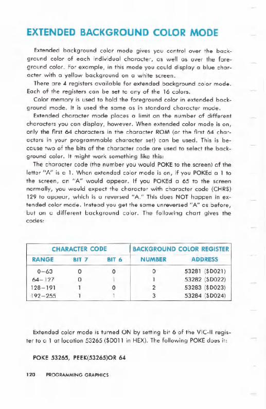
EXTENDED BACKGROUND COLOR MODE
Extended background color mode gives you control over the back-ground color of each individual character, as well as over the fore-ground color. For example, in this mode you could display a blue char-acter with a yellow background on a white screen.
There are 4 registers available for extended background color mode.Each of the registers can be set to any of the 16 colors.
Color memory is used to hold the foreground color in extended back-ground mode. It is used the same as in standard character mode.
Extended character mode places a limit on the number of differentcharacters you can display, however. When extended color mode is on,only the first 64 characters in the character ROM (or the first 64 char-acters in your programmable character set) can be used. This is be-cause two of the bits of the character code are used to select the back-
ground color. It might work something like this:The character code (the number you would POKE.to the. screen) of the
letter "A" is a 1. When extended color mode is on, if you POKEd a 1 tothe screen, an "A" would appear. If you POKEd a 65 to the screennormally, you would expect the character with character code (CHR$)129 to appear, which is a reversed "A." This does NOT happen in ex-tended color mode. Instead you get the same unreversed "A" as before,but on a different background color. The following chart gives thecodes:
Extended color mode is turned ON by setting bit 6 of the VIC-II regis-ter to a .1at location 53265 ($D011 in HEX). The following POKE does it:
POKE 53265, PEEK(53265)OR 64
120 PROGRAMMING GRAPHICS
CHARACTERCODE BACKGROUND COLOR REGISTER
RANGE BIT 7 BIT 6 NUMBER ADDRESS
0-63 0 0 0 53281 ($D021)64-127 0 1 1 53282 ($D022)128-191 1 0 2 53283 ($D023)192-255 1 1 3 53284 ($D024)

Extended color mode is turned OFF by setting bit 6 of the VIC-II regis-ter to a 0 at location 53265 ($D011). The following statement will do this:
POKE 53265, PEEK(53265)AND 191
BIT MAPPED GRAPHICS
When writing games, plotting charts for business applications, orother types of programs, sooner or later you get to the point where youwant high-resolution displays.
The Commodore 64 has been designed to do just that: high resolutionis available through bit mapping of the screen. Bit mapping is themethod in which each possible dot (pixel) of resolution on the screen isassigned its own bit (location) in memory. If that memory bit is a one,the dot it is assigned to is on. If the bit is set to zero, the dot is off.
High-resolution graphic design has a couple of drawbacks, which is
why it is not used all the time. First of all, it takes lots of memory to bitmap the entire screen. This is because every pixel must have a memorybit to control it. You are going to need one bit of memory for each pixel(or one byte for 8 pixels). Since each character is 8 by 8, and there are40 lines with 25 characters in each line, the resolution is 320 pixels (dots)by 200 pixels for the whole screen. That gives you 64000 separate dots,each of which requires a bit in memory. In other words, 8000 bytes ofmemory are needed to map the whole screen.
Generally, high-resolution operations are made of many short, sim-ple, repetitive routines. Unfortunately, this kind of thing is usually ratherslow if you are trying to write high-resolution routines in BASIC. How-ever, short, simple, repetitive routines are exactly what machine lan-guage does best. The solution is to either write your programs entirely inmachine language, or call machine language, high-resolution sub-routines from your BASIC program using the SYS command from BASIC.That way you get both the ease of writing in BASIC, and the speed ofmachine language for graphics. The VSP cartridge is also available toadd high-resolution commands to COMMODORE 64 BASIC.
All of the examples given in this section will be in BASICto make themclear. Now to the technical details.
BITMAPPING is one of the most popular graphics techniques in thecomputer world. It is used to create highly detailed pictures. Basically,when the Commodore 64 goes into bit map mode, it directly displays an
PROGRAMMING GRAPHICS 121

8K section of memory on the TV screen. When in bit map mode, you candirectly control whether an individual dot on the screen is on or off.
There are two types of bit mapping available on the Commodore 64.They are:
1) Standard (high-resolution) bit mapped mode (320-dot by 200-dotresolution)
2) Multi-color bit mapped mode (160-dot by 200-dot resolution)
Each is very similar to the character type it is named for: standard hasgreater resolution, but fewer color selections. On the other hand, multi-color bit mapping trades horizontal resolution for a greater number ofcolors in an 8-dot by a-dot square.
STANDARD HIGH-RESOLUTION BIT MAP MODE
Standard bit map mode gives you a 320 horizontal dot by 200 verticaldot resolution, with a choice of 2 colors in each 8-dot by 8-dot section.Bit map mode is selected (turned ON) by setting bit 5 of the VIC-IIcontrol register to a 1 at location 53265 ($DOll in HEX). The followingPOKE will do this:
POKE 53265,PEEK(53265)OR 32
Bit map mode is turned OFF by setting bit 5 of the VIC-II controlregister to 0 at location 53265 ($D011), like this:
POKE 53265,PEEK(53265)AND 223
Before we get into the details of the bit map mode, there is one moreissue to tackle, and that is where to locate the bit map area.
HOW IT WORKS
If you remember the PROGRAMMABLECHARACTERSsection you willrecall that you were able to set the bit pattern of a character stored in
RAMto almost anything you wanted. If at the same time you change thecharacter that is displayed on the screen, you would be able to changea single dot, and watch it happen. This is the basis of bit-mapping. The
122 PROGRAMMING GRAPHICS

entire screen is filled with programmable characters, and you makeyour changes directly into the memory that the programmable char-acters get their patterns from.
Each of the locations in screen memory that were used to control whatcharacter was displayed, are now used for color information. Forexample, instead of POKEing a 1 in location 1024 to make an "A" ap-pear in the top left hand corner of the screen, location 1024 now con-trols the colors of the bits in that top left space.
Colors of squares in bit map mode do not come from color memory,as they do in the character modes. Instead, colors are taken fromscreen memory. The upper 4 bits of screen memory become the color ofany bit that is set to 1 in the 8 by 8 area controlled by that screenmemory location. The lower 4 bits become the color of any bit that is setto a O.
EXAMPLE:Type the following:
5 BASE=2~4096:POKE53272,PEEK(53272)OR8:REM PUT BITMAP AT 819210 POKE53265,PEEK(53265)OR32:REM ENTER BIT MAP MODE
Now RUN the program.Garbage appears on the screen, right? Just like the normal screen
mode, you have to clear the HIGH-RESOLUTION(HI-RES) screen beforeyou use it. Unfortunately, printing a CLRwon't work in this case. Insteadyou have to clear out the section of memory that you're using for yourprogrammable characters. Hit the .:UIlr~"IIIJ:1and .:I~"IIII:I:IIkeys, thenadd the following lines to your program to clear the HI-RES screen:
20 FORI=BASETOBASE+7999:POKEI,0:NEXT:REM CLEAR BITMAP30 FORI=1024T02023:POKEI,3:NEXT:REM SET COLOR TOC'T'At.~ Arm BLACK
Now RUN the program again. You should see the screen clearing, thenthe greenish blue color, cyan, should cover the whole screen. What wewant to do now is to turn the dots on and off on the HI-RES screen.
PROGRAMMING GRAPHICS 123

To SET a dot (turn a dot ON) or UNSETa dot (turn a dot OFF) you mustknow how to find the correct bit in the character memory that you haveto set to a 1. In other words, you have to find the character you need tochange, the row of the character, and which bit of the row that youhave to change. You need a formula to calculate this.
We will use X and Y to stand for the horizontal and vertical positionsof a dot. The dot where x=o and y=o is at the upper-left of the dis-play. Dots to the right have higher X values, and the dots toward thebottom have higher Y values. The best way to use bit mapping is toarrange the bit map display something like this:
O__n___n_n_n___u_nn_n__nn___n_n_n__ X 000000_00__00_00_0000_0000_00_00_00_00___00 319
y
199 _nOnn_nnn___ __nn_n___nn_nn_n_nn___nn_n_n__nn nnn_nnnnnn_n___
Each dot will have an X and a Y coordinate. With this format it is easyto control any dot on the screen.
124 PROGRAMMING GRAPHICS

However, what you actually have is something like this:
w ~
Zo=;3!l.0OCr!1-- ~
BYTE 0
BYTE 1BYTE 2.
BYTE 3BYTE 4
BYTE 5_
BYTE 6BYTE7
BYTE 8
BYTE 9
BYTE 10
BYTE 11BYTE 12
BYTE 13
BYTE 14
BYTE 15
BYTE 16 BYTE 24 . . . . . . . . .BYTE 312
BYTE313BYTE314BYTE315BYTE316BYTE317BYTE318BYTE319
BYTE 320 BYTE 328 BYTE 336- BYTE 344 . . . . . . .BYTE 632
BYTE 321 BYTE 329 BYTE 633BYTE 322 BYTE 330 BYTE 634BYTE 323 BYTE 331 BYTE 635
BYTE 324 BYTE 332 BYTE 636
BYTE 325 BYTE 333 BYTE 637BYTE 326 BYTE 334 BYTE 638
BYTE 327 BYTE 335 BYTE 639
°3ZoOCr!u~w(/)
The programmable characters which make up the bit map are ar-ranged in 25 rows of 40 columns each. While this is a good method oforganization for text, it makes bit mapping somewhat difficult. (There isa good reason for this method, See the section on MIXED MODES.)
The following formula will make it easier to control a dot on the bitmap screen:
The- start of the display memory area is known as the BASE. The rownumber (from 0 to 24) of your dot is:
ROW = INT(Y/8) (There are 320 bytes per line.)
The character position on that line (from 0 to 39) is:
CHAR = INT(x/8) (There are 8 bytes per character.)
The line of that character position (from 0 to 7) is:
LINE = Y AND 7
PROGRAMMING GRAPHICS 125
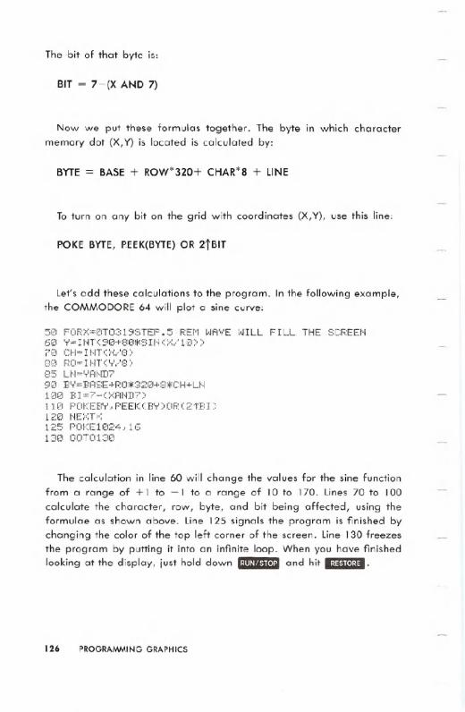
The bit of that byte is:
BIT = 7-(X AND 7)
Now we put these formulas together. The byte in which charactermemory dot (X,Y) is located is calculated by:
BYTE = BASE+ ROW*320+ CHAR*8+ LINE
To turn on any bit on the grid with coordinates (X,V), use this line:
POKE BYTE, P.EEK(BYTE) OR 2jBIT
Let's add these calculations to the program. In the following example,the COMMODORE 64 will plot a sine curve:
5121 FOR:X:=0T0319STEP. 5: REr1 WAVE WILL FILL THE SCREE~I60 Y=INTC9121+80:f.SINCX/1121»7(1 CH= I tH C;";/8::-8121 RO=INTC'T'/8::-85 UI='r'AND790 B'T'=BASE +RO*32121+8*CH+L~11121121BI=7-C:X:AND7)11121 POKEB'r'" PEEK CB'r' ::0OR 0:2 t:E: I ::-12121 t'IE:":n~125 POKE1024..1613121 GOT0130
The calculation in line 60 will change the values for the sine functionfrom a range of + 1 to -1 to a range of 10 to 170. Lines 70 to 100calculate the character, row, byte, and bit being affected, using theformulae as shown above. Line 125 signals the program is finished bychanging the color of the top left corner of the screen. Line 130 freezesthe program by putting it into an infinite loop. When you have finishedlooking at the display, just hold down .:m/'~"tI'I:Iand hit .'1:1.'11I1'1:11.
126 PROGRAMMING GRAPHICS

As a further example, you can modify the sine curve program to dis-playa semicircle. Here are the lines to type to make the changes:
50 FORX=0T0160:REM DO HALF THE SCREEN55 'T' 1 '" 1 iZII21+SC!F: ( 161?!,jo::x:-:;<::t.;:.::)
56 Y2=100-SQR(160:t.X-X*X)60 FORY=Y1TOY2STEPY1-Y27121 CH= nn (:x:/:::)80 RO=U-ITCT'/8)85 .U'I='T'AND7
90 BY=BASE+RO*320+S:t.CH+LN10tC1 E:I=7-C<:At'1Dn
1 H3 POKEB'T'., PEEK (B'T') OR (2 'T'BI )114 ~IEXT
This will create a semicircle in the HI-RES area of the screen.
WARNING: BASIC variables can overlay your high-resolutionscreen. If you need
more memory spaceyou must move thebottomof BASIC above the high-resolution
screen area. Or, you must move your high-resolutionscreen area. Thisproblem will
NOT occur in machine language. ItONLY happens when you're writingprograms inBASIC.
MULTI-COLORBIT MAP MODE
Like multi-color mode characters, multi-color bit map mode allows youto display up to four different colors in each 8 by 8 section of bit map.And as in multi-character mode, there is a sacrifice of horizontal resolu-tion (from 320 dots to 160 dots).
Multi-color bit map mode uses an 8K section of memory for the bitmap. You select your colors for multi-color bit map mode from (1) thebackground color register 0, (the screen background color), (2) the videomatrix (the upper 4 bits give one possible color, the lower 4 bits an-other), and (3) color memory.
Multi-color bit mapped mode is turned ON by setting bit 5 of 53265($D011) and bit 4 at location 53270 ($D016) to a 1. The following POKEdoes this:
POKE 53265,PEEK(53625)OR 32: POKE 53270,PEEK(53270)OR 16
PROGRAMMING GRAPHICS 127
Multi-color bit mapped mode is turned OFF by setting bit 5 of 53265($0011) and bit 4 at location 53270 ($0016) to a O. The following POKEdoes this:
POKE 53265,PEEK(53265)AND 223: POKE 53270,PEEK(53270)AND 239
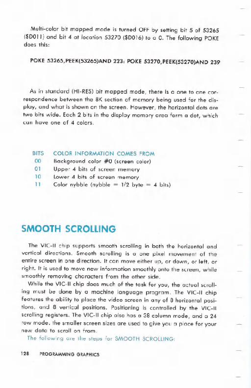
As in standard (HI-RES) bit mapped mode, there is a one to one cor-respondence between the 8K section of memory being used for the dis-play, and what is shown on the screen. However, the horizontal dots aretwo bits wide. Each 2 bits in the display memory area form a dot, whichcan have one of 4 colors.
BITS00011011
COLOR INFORMATION COMES FROM
Background color #0 (screen color)Upper 4 bits of screen memorylower 4 bits of screen memoryColor nybble (nybble = 1/2 byte = 4 bits)
SMOOTH SCROLLING
The VIC-II chip supports smooth scrolling in both the horizontal andvertical directions. Smooth scrolling is a one pixel movement of theentire screen in one direction. It can move either up, or down, or left, orright. It is used to move new information smoothly onto the screen, whilesmoothly removirlg characters from the other side.
While the VIC-II chip does much of the task for you, the actual scroll-ing must be done by a machine language program. The VIC-II chipfeatures the ability to place the video screen in any of 8 horizontal posi-tions, and 8 vertical positions. Positioning is controlled by the VIC-IIscrolling registers. The VIC-II chip also has a 38 column mode, and a 24
row mode. the smaller screen sizes are used to give you a place for yournew data to scroll on from.
The following are the steps for SMOOTH SCROLLING:
128 PROGRAMMINGGRAPHICS
1) Shrink the screen (the border will expand).
2) Set the scrolling register to maximum (or minimum value depend-ing upon the direction of your scroll).
3) Place the new data on the proper (covered) portion of the screen.4) Increment (or decrement) the scrolling register until it reaches the
maximum (or minimum) value.
5) At this point, use your machine language routine to shift the entirescreen one entire character in the direction of the scroll.
6) Go back to step 2.
To go into 38 column mode, bit 3 of location 53270 ($D016) must beset to a O. The following POKE does this:
POKE 53270,PEEK(53270)AND 247
To return to 40 column mode, set bit 3 of location 53270 ($D016) to a1. The following POKE does this:
POKE 53270,PEEK(53270)OR 8
To go into 24 row mode, bit 3 of location 53265 ($D011) must be set toa O. The following POKE will do this:
POKE 53265,PEEK(53265)AND 247
To return to 25 row mode, set bit 3 of location 53265 ($DOll) to a 1.The following POKE does this:
POKE 53265,PEEK(53265)OR 8
Whe, scrolling in the X direction, it is necessary to place "the VIC-IIchip into 38 column mode. This gives new data a place to scroll from.When scrolling LEFT,the new data should be placed on the right. Whenscrolling RIGHT the new data should be placed on the left. Please notethat there are still 40 columns to screen memory, but only 38 are visible.
When scrolling in the Ydirection, it is necessary to place the VIC-II chipinto 24 row mode. When scrolling UP, place the new data in the LASTrow. When scrolling DOWN, place the new data on the FIRSTrow. Un-like X scrolling, where there are covered areas on each side of the
screen, there is only one covered area in Y scrolling. When the Y scroll-
PROGRAMMINGGRAPHICS 129

ing register is set to 0, the first line is covered, ready for new data.When the Y scrolling register is set to 7 the last row is covered.
For scrolling in the X direction, the scroll register is located in bits 2 too of the VIC-II control register at location 53270 ($DOI6 in HEX). Asalways, it is important to affect only those bits. The following POKEdoesthis:
POKE 53270, (PEEK(53270)AND 248)+X
where X is the X position of the screen from 0 to 7.For scrolling in the Y direction, the scroll register is located in bits 2 to
o of the VIC-II control register at location 53265 ($DOII in HEX). Asalways, it is important to affect only those bits. The following POKEdoesthis:
POKE 53265, (PEEK(53265)AND 248)+Y
where Y is the Y position of the screen from 0 to 7.To scroll text onto the screen from the bottom, you would step the
low-order 3 bits of location 53265 from 0-7, put more data on thecovered line at the bottom of the screen, and then repeat the process.To scroll characters onto the screen from left to right, you would step thelow-order 3 bits of location 53270 from 0 to 7, print or POKE anothercolumn of new data into column 0 of the screen, then repeat the pro-cess.
If you step the scroll bits by -I, your text will move in the oppositedirection.
EXAMPLE:Text scrolling onto the bottom of the screen:
10 POKE53265,PEEK(53265)AND247INTO 24 ROW MODE2121PRINTCHR$(147)CLEAR THE SCREEN30 FORX=lT024:PRINTCHR$(17); :NEXTTHE CURSOR TO THE BOTTOM40 POKE53265,(PEEK(53265)AND248)+7:PRINTPOSITION FOR 1ST SCROLL5121 PRItHII HELLOII;6121FORP=6T00STEP-170 POKE53265,(PEEK(53265>AND24S)+P8121FORX=lT050:NEXT :REMDELAo,.' LOOP
910 t~E:>o:T:GOT041O
:REM GO
:REM
:REM MOVE
:REr1
130 PROGRAMMING GRAPHICS

SPRITES
A SPRITE is a special type of user definable character which can be
displayed anywhere on the screen. Sprites are maintained directly bythe VIC-II chip. And all you have to do is tell a sprite "what to look like,""what color to be," and "where to appear." The V/C-II chip will do therest! Sprites can be any of the 16 colors available.
Sprites can be used with ANY of the other graphics modes, bit":lapped, character, multi-color, etc., and they'll keep their shape in allof them. The sprite carries its own color definition, its own mode (HI-RESor multi-colored), and its own shape.
Up to 8 sprites at a time can be maintained by the VIC-II chip auto-matically. More sprites can be displayed using RASTER INTERRUPTtechniques.
The features of SPRITESinclude:
1) 24 horizontal dot by 21 vertical dot size.2) Individual color control for each sprite.3) Sprite multi-color mode.4) Magnification (2X) in horizontal, vertical, or both directions.5) Selectable sprite to background priority.6) Fixed sprite to sprite priorities.7) Sprite to sprite collision detection.8) Sprite to background collision detection.
These special sprite abilities make it simple to program many arcadestyle games. Because the sprites are maintained by hardware, it is evenpossible to write a good quality game in BASIC!
Th( r.3 are 8 sprites supported directly by the VIC-II chip. They arenumbered from 0 to 7. Each of the sprites has it own definition location,position registers and color register, and has its own bits for enable andcollision detection.
DEFINING A SPRITE
Sprites are defined like programmable characters are defined. How-ever, since the size of the sprite is larger, more bytes are needed. Asprite is 24 by 21 dots, or 504 dots. This works out to 63 bytes (504/8
PROGRAMMINGGRAPHICS 131

-Co)
..,""00
Z "'II0 10.0 c
iiJ..,Co)J:n .to.)en .VI"U...:;:CDCCD:!)
:;:irD:J
0-n
COLUMN 00 01 02 03 04 05 06 07 08 09 10 11 12 13 14 15 16 17 18 19 20 21 22 23NUMBER
BIT 7 6 5 4 3 2 1 0 7 6 5 4 3 2 1 0 7 6 5 4 3 2 1 0
BITDATAVALUES 128 64 32 16 8 4 2 1 128 64 32 16 8 4 2 1 128 64 32 16 8 4 2 1(ON .dxVAL)
ROW0
ROW1
ROW2
ROW3
ROW4
ROW5
ROW6
ROW7
ROW8
ROW9
ROW10
ROW11
ROW12
ROW13
ROW14
ROW15
ROW16
ROW17
ROW18ROW19
ROW20
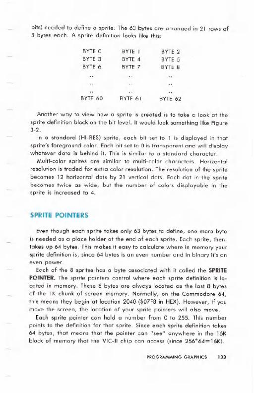
bits) needed to define a sprite. The 63 bytes are arranged in 21 rows of3 bytes each. A sprite definition looks like this:
BYTE0BYTE3BYTE6
BYTE1BYTE4BYTE7
BYTE2BYTE5BYTE8
BYTE 60 BYTE 61 BYTE 62
Another way to view how a sprite is created is to take a look at the
sprite definition block on the bit level. It would look something like Figure3-2.
In a standard (HI~RES)sprite, each bit set to 1 is displayed in thatsprite's foreground color. Each bit set to 0 is transparent and will displaywhatever data is behind it. This is similar to a standard character.
Multi-color sprites are similar to multi-color characters. Horizontal
resolution is traded for extra color resolution. The resolution of the spritebecomes 12 horizontal dots by 21 vertical dots. Each dot in the spritebecomes twice as wide, but the number of colors displayable in thesprite is increased to 4.
SPRITE POINTERS
Even though each sprite takes only 63 bytes to define, one more byteis needed as a place holder at the end of each sprite. Each sprite, then,takes up 64 bytes. This makes it easy to calculate where in memory yoursprite definition is, since 64 bytes is an even number and in binary it's aneven power.
EC'ch of the 8 sprites has a byte associated with it called the SPRITEPOINTER.The sprite pointers control where each sprite definition is lo-cated in memory. These 8 bytes are always located as the last 8 bytesof the 1K chunk of screen memory. Normally, on the Commodore 64,this means they begin at location 2040 ($07F8 in HEX). However, if youmove the screen, the location of your sprite pointers will also move.
Each sprite pointer can hold a number from 0 to 255. This numberpoints to the definition for that sprite. Since each sprite definition takes64 bytes, that means that the pointer can "see" anywhere in the 16Kblock of memory that the VIC-II chip can access (since 256*64= 16K).
PROGRAMMING GRAPHICS 133
If sprite pointer #0, at location 2040, contains the number 14, forexample, this means that sprite 0 will be displayed using the 64 bytesbeginning at location 14*64 = 896 which is in the cassette buffer. Thefollowing formula makes this clear:
LOCATION = (BANK * 16384) + (SPRITEPOINTER VALUE* 64)
Where BANK is the 16K segment of memory that the VIC-II chip is look-ing at and is fr~m 0 to 3.
The above formula gives the start of the 64 bytes of the spritedefinition block.
When the VIC-II chip is looking at BANK0 or BANK 2, there is a ROMIMAGE of the character set present in certain locations, as mentionedbefore. Sprite definitions can NOT be placed there. If for some reasonyou need more than 128 different sprite definitions, you should use oneof the banks without the ROM IMAGE, 1 or 3.
TURNING SPRITES ON
The VIC-II control register at location 53269 ($D015 in HEX) is known
as the SPRITE ENABLE register. Each of the sprites has a bit in thisregister which controls whether that sprite is ON or OFF. The registerlooks like this:
$D015 7 6 5 4 3 2 1 0
To turn on sprite 1, for example, it is necessary to turn that bit to a I.The following POKE does this:
POKE 53269,PEEK(53269)OR 2
A more general statement would be the following:
POKE 53269,PEEK(53269}OR (2tSN)
where SN is the sprite number, from 0 to 7.
NOTE: A sprite must be turned ON before it con be seen.
134 'PROGRAMMING GRAPHICS
TURNING SPRITES OFF
A sprite is turned off by setting its bit in the VIC-lIcontrol register at53269 ($0015 in HEX) to a O. The following POKE will do this:
POKE 53269, PEEK(53269)AND (255-2jSN)
where SN is the sprite number from 0 to 7.
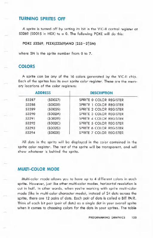
COLORS
A sprite can be any of the 16 colors generated by the VIC-II chip.Each of the sprites has its own sprite color register. These are the mem-ory locations of the color registers:
5328753288
5328953290
5329153292
5329353294
ADDRESS
($0027)
($0028)
($0029)
($002A)
($0026)
($002C)
($0020)
($002E)
DESCRIPTION
SPRITE 0 COLOR REGISTER
SPRITE 1 COLOR REGISTER
SPRITE 2 COLOR REGISTERSPRITE 3 COLOR REGISTER
SPRITE 4 COLOR REGISTER
SPRITE 5 COLOR REGISTER
SPRITE 6 COLOR REGISTER
SPRITE 7 COLOR REGISTER
All dots in the sprite will be displayed in the color contained in thesprite color register. The rest of the sprite will be transparent, and willshow whatever is behind the sprite.
MULTI-COLOR MODE
Multi-color mode allows you to have up to 4 different colors in eachsprite. However, just like other multi-color modes, horizontal resolution iscut in half. In other words, when you're working with sprite multi-colormode (like in multi-color character mode), instead of 24 dots across thesprite, there are 12 pairs of dots. Each pair of dots is called a BIT PAIR.Think of each bit pair (pair of dots) as a single dot in your overall spritewhen it comes to choosing colors for the dots in your sprites. The table
PROGRAMMING GRAPHICS 135
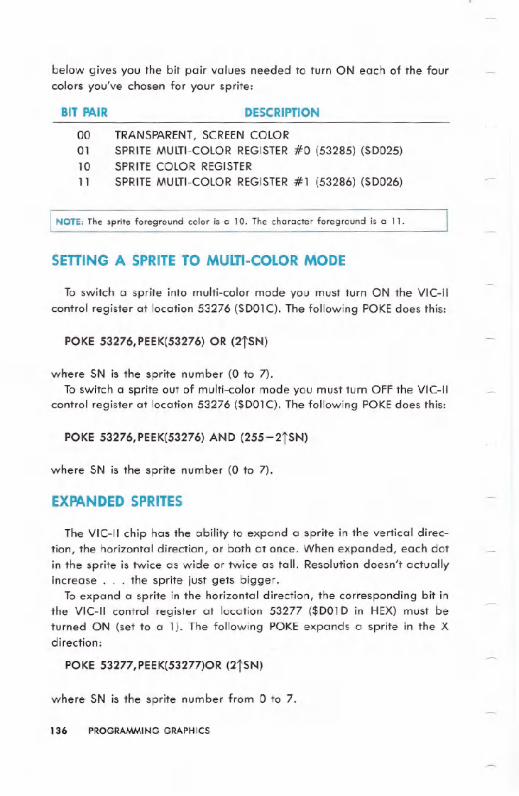
below gives you the bit pair values needed to turn ON each of the fourcolors you've chosen for your sprite:
BIT PAIR DESCRIPTION
00 TRANSPARENT,SCREEN COLOR01 SPRITE MULTI-COLORREGISTER#0 (53285) ($D025)10 SPRITE COLOR REGISTER
11 SPRITEMULTI-COLORREGISTER#1 (53286) ($D026)
NOTE: The sprite foreground color is a 10. The character foreground is a 11.
SEnlNG A SPRITE TO MULTI-COLORMODE
To switch a sprite into multi-color mode you must turn ON the VIC-IIcontrol register at location 53276 ($D01C). The following POKEdoes this:
POKE 53276,PEEK(53276) OR (2tSN)
where SN is the sprite number (O to 7).To switch a sprite out of multi-color mode you must turn OFF the VIC-II
control register at location 53276 ($D01C). The following POKEdoes this:
POKE 53276,PEEK(53276) AND (255-2tSN)
where SN is the sprite number (O to 7).
EXPANDED SPRITES
The VIC-II chip has the ability to expand a sprite in the vertical direc-tion, the horizontal direction, or both at once. When expanded, each dotin the sprite is twice as wide or twice as tall. Resolution doesn't actuallyincrease. . . the sprite just gets bigger.
To expand a sprite in the horizontal direction, the corresponding bit inthe VIC-IIcontrol register at location 53277 ($D01D in HEX)must beturned ON (set to a 1). The following POKEexpands a sprite in the Xdirection:
POKE 53277,PEEK(53277)OR (2tSN)
where SN is the sprite number from 0 to 7.
136 PROGRAMMING GRAPHICS
To unexpand a sprite in the horizontal direction, the corresponding bitin the VIC-II control register at location 53277 ($DOID in HEX) must beturned OFF (set to a 0). The following POKE "unexpands" a sprite in theX direction:
POKE 53277,PEEK(53277)AND (255-2tSN)
where SN is the sprite number from 0 to 7.
To expand a sprite in the vertical direction, the corresponding bit inthe VIC-II control register at location 53271 ($DOI7 in HEX) must beturned ON (set to a 1). The following POKE expands a sprite in the Ydirection:
POKE 53271, PEEK{53271)OR (2tSN)
where SN is the sprite number from 0 to 7.
To unexpand a sprite in the vertical direction, the corresponding bit inthe VIC-II control register at location 53271 ($DOI7 in HEX) must beturned OFF (set to a 0). The following POKE "unexpands" a sprite in theY direction:
POKE 53271,PEEK(53271)AND (255-2tSN)
where SN is the sprite number from 0 to 7.
SPRITE POSITIONING
Once you've made a sprite you want to be able to move it around thescreen. To do this, your Commodore 64 uses three positioning registers:
1) SPRITE X POSITION REGISTER
2) SPRITE Y POSITION REGISTER
3) MOST SIGNIFICANT BIT X POSITION REGISTER
Each sprite has an X position register, a Y position register, and a bitin the X most significant bit register. This lets you position your spritesvery accurately. You can place your sprite in 512 possible X positionsand 256 possible Y positions.
The X and Y position registers work together, in pairs, as a team. Thelocatkms of the X and Y registers appear in the memory map as follows:First is the X register for sprite 0, then the Y register for sprite O. Next
PROGRAMMINGGRAPHICS 137
comes the X register for sprite 1, the Y register for sprite 1, and so on.After all 16 X and Y registers comes the most significant bit in the Xposition (X MSB) located in its own register.
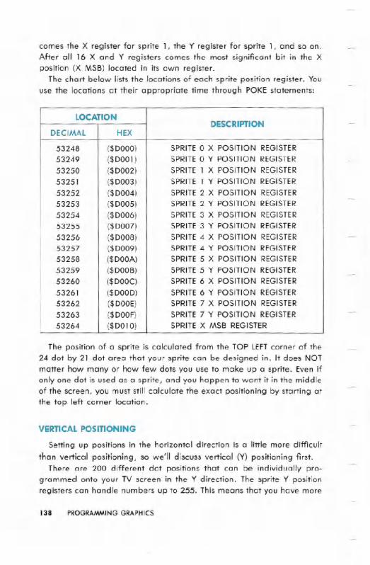
The chart below lists the locations of each sprite position register. You
use the locations at their appropriate time through POKEstatements:
The position of a sprite is calculated from the TOP LEFTcorner of the
24 dot by 21 dot area that your sprite can be designed in. It does NOTmatter how many or how few dots you use to make up a sprite. Even ifonly one dot is used as a sprite, and you happen to want it in the middle
of the screen, you must still calculate the exact positioning by starting atthe top left corner location.
VERTICAL POSITIONING
Setting up positions in the horizontal direction is a little more difficult
than vertical positioning, so we'll discuss vertical (Y) positioning first.
There are 200 different dot positions that can be individually pro-
grammed onto your TV screen in the Y direction. The sprite Y position
registers can handle numbers up to 255. This means that you have more
138 PROGRAMMINGGRAPHICS
LOCATIONDESCRIPTION
DECIMAL HEX
53248 ($DOOO) SPRITE 0 X POSITION REGISTER
53249 ($DOOI ) SPRITE 0 Y POSITION REGISTER
53250 ($D002) SPRITE 1 X POSITION REGISTER
53251 ($D003) SPRITE 1 Y POSITION REGISTER
53252 ($D004) SPRITE 2 X POSITION REGISTER
53253 ($D005) SPRITE 2 Y POSITION REGISTER
53254 ($D006) SPRITE 3 X POSITION REGISTER
53255 ($D007) SPRITE 3 Y POSITION REGISTER
53256 ($D008) SPRITE 4 X POSITION REGISTER
53257 ($D009) SPRITE 4 Y POSITION REGISTER53258 ($DOOA) SPRITE 5 X POSITION REGISTER53259 ($DOOB) SPRITE 5 Y POSITION REGISTER
53260 ($DOOC) SPRITE 6 X POSITION REGISTER
53261 ($DOOD) SPRITE 6 Y POSITION REGISTER
53262 ($DOOE) SPRITE 7 X POSITION REGISTER
53263 ($DOOF) SPRITE 7 Y POSITION REGISTER
53264 ($D010) SPRITE X MSB REGISTER
than enough register locations to handle moving a sprite up and down.You also want to be able to smoothly move a sprite on and off thescreen. More than 200 values are needed for this.
The first on-screen value from the top of the screen, and in the Ydirection for an unexpanded sprite is 30. For a sprite expanded in the Ydirection it would be 9. (Since each dot is twice as tall, this makes acertain amount of sense, as the initial position is STILLcalculated fromthe top left corner of the sprite.)
The first Y value in which a sprite (expanded or not) is fully on thescreen (all 21 possible lines displayed) is 50.
The last Y value in which an unexpanded sprite is fully on the screen is229. The last Y value in which an expanded sprite is fully on the screenis 208.
The first Y value in which a sprite is fully off the screen is 250.
EXAMPLE:
---mD~1121PRnn":T - : REt'1 CLEAF.: SCF.:EEt,120 POKE2040 , 13 :REM GET SPRITE 0DATA FROM BLOCK 1330 FORI=OT062:POKE832+I,129'NEXT:REM POKE SPRITEDATA INTO BLOCK 13 (13*64=832)40 V=53248 :REM SET BEGINNINGOF VIDEO CHIP5121POKEV+21" 1 : F.'Et1 EI"IABLE ~;PRITE160 pm~E""'+:39., 1COLOR71<:1POKE '+ 1 " 11210'T' POSITIO~I80 POKEV+16,0:POKEV,100>': POSITION
:REM SET SPRITE (1
:REM SET SPRITE 0
:REM SET SPRITE 121
HORIZONTAL POSITIONING
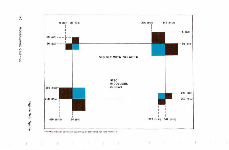
Positioning in the horizontal direction is more complicated becausethere are more than 256 positions. This means that an extra bit, or 9thbit is used to control the X position. By adding the extra bit when neces-sary a sprite now has 512 possible positions in the left/right, X, direc-tion. This makes more possible combinations than can be seen on thevisible part of the screen. Each sprite can have a position from 0 to 511.
However, only those values between 24 and 343 are visible on thescreen. If the X position of a sprite is greater than 255 (on the right sideof the screen), the bit in the X MOST SIGNIFICANTBITPOSITION registermust be set to a 1 (turned ON). If the X position of a sprite is less than
PROGRAMMINGGRAPHICS 139
-".o
...'"o
~ZC>C>~...:rnC/I
'ft
cO.e;Co)ICo)
en"U...:;:CD
o (SOO) 24 (S18)I II II II I
29 (S1D) -- - L _II50 (S32) ___I
208 ($DO)-
250 (SFA)-IIIIII
488 (S1E8)
III
24 (S18)
VISIBLEVIEWING AREA
NTSC'40 COLUMNS25 ROWS
.North American televisiontransmissionstandardsfor your home TV.
296 (S128)III
344 ($158)II
1 8 ($08)
IIII
320 (S140)
-- 50 ($32)
-- - 229 ($E5)
-- - 250 ($FA)
I1II
344 (S158)

~II>:;:cr~:rcon:s-a::I-!II
"'"oG')~~zG')
G')
~"J:nVI
~
7 ($07) 31 ($1F)I II II 1I II 1
33 ($211 __ - _1__1I
54 ($36) I
204 ($CCI- -
246 ($F6)- -,IIIIII
480 ($1EO)
131 ($1F)
VISIBLE VIEWING AREA
NTSC.38 COLUMNS24 ROWS
.North American television transmission standards for your home TV.
287 ($11FII111
335 ($14FIII1
, 1- _ _ _ _ _ _ 12 ($OC)
- - 54($36)
- ---225 ($E1)
- - - -246 I$F6)
1II11
311 ($137)
IIIIII
335 ($14FI
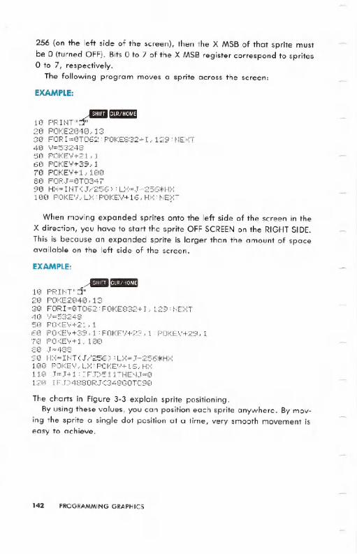
256 (on the left side of the screen), then the X MSB of that sprite mustbe 0 (turned OFF). Bits 0 to 7 of the X MSB register correspond to spriteso to 7, respectively.
The following program moves a sprite across the screen:
EXAMPLE:
--IDIIiI"10 PF.:It-IT"::T'-20 F'OKE2040.1330 FORI=0T062:POKE832+I.129:NEXT40 ..,.=5:324:350 POKE'.'!+21,. 16121POKE"'!+3S<..170 POKEV+ 1 " 1121(18121FOF(J=!3TOcH790 HX=INTeJ/256)'LX=J-256*HX100 POKEV.LX:POKEV+16.HX:NE~T
When moving expanded sprites onto the left side of the screen in theX direction, you have to start the sprite OFFSCREENon the RIGHTSIDE.Thisis because an expanded sprite is larger than the amount of spaceavailable on the left side of the screen.
EXAMPLE:
,ABI"1121pF.:nn":J"2(1 F'OKE2!~140. 1330 FORI=0T062:POKE832+I.129:NEXT4121 \.':=::5::':24850 POKE','!+21" 160 POKEV+39.1:POKEV+23.1:POKEV+29.170 POKE'.,!+1 . 10(~:3121J~48:::90 HX=INTeJ/256):LX=J-256*HX100 POKEV,LX:POKEV+16.HX110 J=J+l:IFJ)511THENJ=0120 IFJ)4880RJ<348GOT090
The charts in Figure 3-3 explain sprite positioning.
By using these values, you can position each sprite anywhere. By mov-ing the sprite a single dot position at a time, very smooth movement iseasy to achieve.
142 PROGRAMMING GRAPHICS
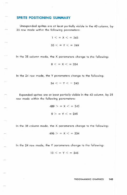
SPRITE POSITIONING SUMMARY
Unexpanded sprites are at least partially visible in the 40 column, by25 row mode within the following parameters:
1 < = X < = 343
30 < = y < = 249
In the 38 column mode, the X parameters change to the following:
8 < = X < = 334
In the 24 row mode, the Y parameters change to the following:
34 < = Y < = 245
Expanded sprites are at least partially visible in the 40 column, by 25row mode within the following parameters:
489 > = X < = 343
9 > = Y < = 249
In the 38 column mode, the X parameters change to the following:
1496> = X < = 334
In the 24 row mode, the Y parameters change to the following:
13 < = Y < = 245
PROGRAMMING GRAPHICS 143
SPRITE DISPLAY PRIORITIES
Sprites have-the ability to cross each other's paths, as well as cross infront of, or behind other objects on the screen. This can give you a trulythree dimensional effect for games.
Sprite to sprite priority is fixed. That means that sprite 0 has the high-est priority, sprite 1 has the next priority, and so on, until we get tosprite 7, which has the lowest priority. In other words, if sprite 1 andsprite 6 are positioned so that they cross each other, sprite 1 will be infront of sprite 6.
So when you're planning which sprites will appear to be in the fore-ground of the picture, they must be assigned lower sprite numbers thanthose sprites you want to put towards the back of the scene. Thosesprites will be given higher sprite numbers.
NOTE: A "window" effect is possible. If a sprite with higher priority has "holes" in it(areas where the dots are not set to 1 and thus turned ON), the sprite- with the lower
priority will show through. This also happens with sprite and background data.
Sprite to background priority is controllable by the SPRITE-BACK-GROUND priority register located at 53275 ($DOIB). Each sprite has abit in this register. If that bit is 0, that sprite has a higher priority thanthe background on the screen. In other words, the sprite appears infront of background data. If that bit is aI, that sprite has a lowerpriority than the background. Then the sprite appears behind the back-ground data.
COLLISION DETECTS
One of the more interesting aspects of the VIC-II chip is its collisiondetection abilities. Collisions can be detected between sprites, or be-tween sprites and background data. A collision occurs when a non-zeropart of a sprite overlaps a non-zero portion of another sprite or char-acters on the screen.
144 PROGRAMMINGGRAPHICS

SPRITE TO SPRITE COLLISIONS
Sprite to sprite collisions are recognized by the computer, or flagged,in the spite to sprite collision register at location 53278 ($DOlE in HEX) inthe VIC-II chip control register. Each sprite has a bit in this register. Ifthat bit is a 1, then that sprite is involved in a collision. The bits in thisregister will remain set until read (PEEKed). Once read, the register isautomatically cleared, so it is a good idea to save the value in a vari-able until you are finished with it.
NOTE: Collisions can take place even when the sprites are off screen.
SPRITE TO DATA COLLISIONS
Sprite to data collisions are detected in the sprite to data collisionregister at location 53279 ($DOlF in HEX)of the VIC-II chip control regis-ter.
Each sprite has a bit in this register. If that bit is a 1, then that spriteis involved in a collision. The bits in this register remain set until read(PEEKed). Once read, the register is automatically cleared, so it is agood idea to save the value in a variable until you are finished with it.
NOTE: MULTI-COLORdata 01 is considered transparent for collisions, even though it
shows up on the screen. When setting up a background screen, it is a good idea tomake everything that should not cause a collision 01 in multi-color mode.
PROGRAMMING GRAPHICS 145
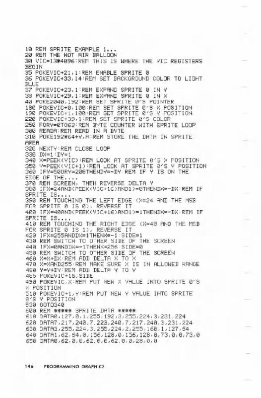
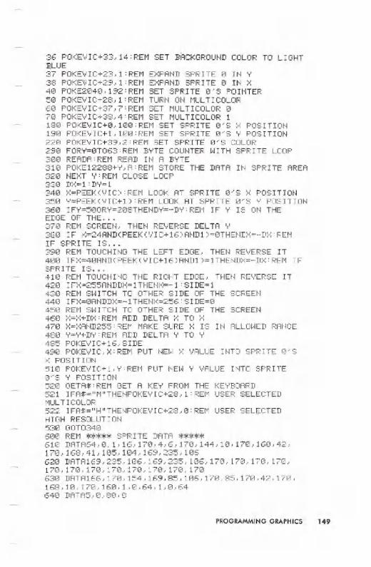
10 REM SPRITE EXAMPLE 1...20 REM THE HOT AIR BALLOON30 VIC=13~4096:REM THIS IS WHERE THE VIC REGISTERSBEGIN35 POKEVIC+21,1:REM ENABLE SPRITE 036 POKEVIC+33, 14:REM SET BACKGROUND COLOR TO LIGHTBLUE37 POKEVIC+23,1:REM EXPAND SPRITE 0 IN Y38 POKEVIC+29,1:REM EXPAND SPRITE 0 IN X40 POKE2040 ,192:REM SET SPRITE 0~S POINTER180 POKEVIC+0,100:REM SET SPRITE 0~S X POSITION190 POKEVIC+l, 100:REM SET SPRITE 0~S Y POSITION220 POKEVIC+39,1:REM SET SPRITE 0~S COLOR250 FORY=0T063:REM BYTE COUNTER WITH SPRITE LOOP300 READA:REM READ IN A BYTE310 POKE192*64+Y,A:REM STORE THE DATA IN SPRITEAREA320 I~EXT'T':REM CLOSE LOOP330 DX=l:DY=l340 X=PEEK(VIC):REM LOOK AT SPRITE 0~S X POSITION350 Y=PEEK(VIC+l):REM LOOK AT SPRITE 0~S Y POSITION360 IFY=500RY=208THENDY=-DY:REM IF Y IS ON THEEDGE OF THE....370 REt1 SCREEN, THEt~ REVERSE DELTA Y380 IFX=24AND(PEEK(VIC+16)AND1)=0THENDX=-DX:REM IFSPRITE IS....390 REM TOUCHIt~GTHE LEFT EDGE (>::=24 At~DTHE MSBFOR SPRITE 0 IS 0), REVERSE IT400 IFX=40AND(PEEK(VIC+16)AND1)=lTHENDX=-DX:REM IFSPRITE IS....410 REI1 TOUCHI.NG THE RIGHT EDGE (X=40 AND THE t1SBFOR SPRITE 0 IS 1), REVERSE IT420IFX=255ANDDX=lTHENX=-1:SIDE=1430 REM SWITCH TO OTHER SIDE OF THE SCREEN440 IFX=0ANDDX=-lTHENX=256:SIDE=0450 REM SWITCH TO OTHER SIDE OF THE SCREEN460 X=X+DX:REM ADD DELTA X TO X470 X=XAND255:REM MAKE SURE X IS IN ALLOWED RANOE480 Y=Y+DY:REM ADD DELTA Y TO Y485 POKEVIC+16,SIDE490 POKEVIC,X:REM PUT NEW X VALUE INTO SPRITE 0~SX POSITION510 POKEVIC+1,Y:REM PUT NEW Y VALUE INTO SPRITE0~S 'iPOSITION530 OOT0340600 REM ***** SPRITE DATA *****610 DATA0,127,0,1,255,192,3,255,224,3,231,224620 DATA7,217,240,7,223,240,7,217,240,3,231,224630 DATA3,255,224,3,255,224,2,255,160, 1,127,64640 DATAl,62,64,0,156,128,e,156,128,0,73,a,a,73,a650 DATA0,62,0,0,62,0,0,62,0,0,28,a,0
146 PROGRAMMING GRAPHICS

10 REt'l SPRITE E:":AMPLE 2...20 REM THE HOT AIR BALLOON AGAIN30 VIC=13*4096:REM THIS IS WHERE THE VIC REGISTERSBEGIN35 POKEVIC+21,63:REM ENABLE SPRITES 0 THRU 536 POKE"I IC+33., 14 :REM SET BACKGROUt.jD COLOR TO LIGHT:BLUE37 POKE"lIC+23.,:3: REf'l E:";PAND SPRITES 0 AND 1 IN 'T'38 POKEY IC+29., 3 : REt1 E>::PAt~D SPR IrES 0 AND 1 HI X40 POKE2040, 192:REM SET SPRITE 0~S POINTER50 POKE2041 ,193:REM SET SPRITE l~S POINTER60 POKE2042, 192:REM SET SPRITE 2~S POINTER70 POKE2043, 193:REM SET SPRITE 3~S POINTER80 POKE2044.. 192:REM SET SPRITE 4~S POINTER90 POKE2045, 193:REM SET SPRITE 5~S POINTER100 POKEVIC+4,30:REM SET SPRITE 2~S X POSITION110 POKEY I C+5, 58 :REM SET SPR ITE 2 ~ S ',JPOS ITI ON
120 POKEVIC+6,65:REM SET SPRITE 3~S X POSITION130 POKEVIC+7,58:REM SET SPRITE 3'S Y POSITION140 POKEVIC+8, 100:REM SET SPRITE 4~S X POSITION150 POKEVIC+9,58:REM SET SPRITE 4~S Y POSITION160 POKEVIC+10, 100:REM SET SPRITE 5'S X POSITION17(1 POKE..,.IC+ 11 , 58 :REM SET SPR IrE 5' S Y POS IT IO~!
J81J175 PRINT" i:(']"TAB(15) "THIS IS TWO HIRES SPRITES".;
'mil"176 PR HITTAB (55) "Ot.!TOP OF EACH OTHER"180 POKEVIC+0,100:REM SET SPRITE 0~S X POSITION190 POKEVIC+1, 100:REM SET SPRITE 0'S Y POSITION200 POKEVIC+2, 100:REM SET SPRITE l'S X POSITION210 POKEVIC+3, 100:REM SET SPRITE l~S Y POSITION220 POKEVIC+39,1:REM SET SPRITE 0'S COLOR230 POKEVIC+41,1:REM SET SPRITE 2~S COLOR240 POKEVIC+43,1:REM SET SPRITE 4'S COLOR.250 POKEV IC+40., 6 :REt1 SET SPFU TE l' S COLOF.:
260 POKEVIC+42,6:REM SET SPRITE 3'S COLOR270 POKEVIC+44,6:REM SET SPRITE 5'S COLOR280 FORX=192T0193:REM THE START OF THE LOOP THATDEFINES THE SPRITES290 FORY=0T063:REM BYTE COUNTER WITH SPRITE LOOP300 READA:REMREAD IN A BYTE:310 POKE~<::+:64+Y,A :F.:E~1STORE THE DATA It-! SPR ITE AREFI320 NEXTY,X:REM CLOSE LOOPS330 D>::= 1 :DY= 1
340 X=PEEK(VIC):REM LOOK AT SPRITE 0~S X POSITION350 Y=PEEK(VIC+l):REM LOOK AT SPRITE 0'S Y POSITION360 IF'T'=500RY=208THEND'r'=-DY: REt1 IF 'T' IS ON THE
EDGE OF THE...370 REM SCREEN, THEN REVERSE DELTA Y380 IFX=24AND(PEEK(VIC+16)AND1)=0THENDX=-DX:REMIFSPRITE IS...390 REM TOUCHING THE LEFT EDGE, THEN REVERSE IT
PROGRAMMING GRAPHICS 147

400 I FK=40FH.m 0::PEEK 0::I.,.'I C+ 16) At.m 1) =1THE~m>,;=- Dr.:: REt1 IFSPRITE IS...410 REM TOUCHING THE RIGHT EDGE, THEN REVERSE IT420 IFX=255ANDDX=1THENX=-1:SIDE=343(1 REt1 SJ..JITCH TO OTHER S I DE OF THE SCREEN440 IF:.:=0At.mm':=-1 THEN:X:=256: SIDE=0450 REM SWITCH TO OTHER SIDE OF THE SCREEN460 :.:=:.:+m,:: REt1 ADD DELTA ::-::TO :.:470 X=XAND255:REM MAKE SURE X IS IN ALLOWED RANGE480 Y=Y+DY:REM ADD DELTA Y TO Y485 POKEVIC+16,SIDE490 POKEVIC,X:REM PUT NEW X VALUE INTO SPRITE O'S?~ POSITIm~500 POKEVIC+2, >:::REt1 PUT ~~EW:x: I'..'ALUE uno SPRITE1 ':3 :.: POS IT ION510 POKEVIC+l.Y:REM PUT NEW Y VALUE INTO SPRITEO'S Y POSITIO~~520 POKEV!C+3,Y:REM PUT NEW Y VALUE INTO SPRITE1'S 'r POSITIO~~530 GOT0340600 REM ***** SPRITE DATA *****610 DATA0,255,0,3,153,192,7,24,224,7,56,224,14, 126,112,14,126,112,14,126,112620 DATA6, 126,96,7,56,224,7,56,224,i,56,128,O,153,0,0,90, (I, 0, 56.. °6313 DATAO,56,0,0,0,O,O,O,O,O,12G,e,e,42,e,0,84,e,o,413..0,0640 DATAo,e,O,0,102,0,0,231,0,0,195,0,i,129,128,1,129,128,1,129,128650 DATA1,12~,128,0,195,O,0,195,0,4,195,32,2,102,64,2,36,64,1,0,128660 DATA1,0,128,0,153,O,O,153,O,O,0,O,0,84,0,O,42,O,O,20,O,O
10 REt1 SPR ITE EXAMPLE3...213 REM THE HOT AIR GORF30 VIC=53248:REM THIS IS WHERE THE VIC REGISTERSBEGIN35 POKEVIC+21,1: REME~IABLESPRITE 0
148 PROGRAMMING GRAPHICS
36 POKEVIC+33, 14:REM SET BACKGROUND COLOR TO LIGHTB..LUE37 POKEVIC+23,1:REM EXPAND SPRITE 121IN ~38 POKE~IC+29,1:REM EXPAND SPRITE 121IN X40 POKE2€140, 192:REM SET SPRITE 0'8 PO HnEI':5121 F'OKEVIC+28, 1:REt1 TURN O~j MULTICOLOR60 POKEVIC+37,7:REM SET MULTICOLOR 1217121POKEVIC+38,4:REM SET MULTICOLOR 1180 POKEVIC+I2I, 1121121:REM SET SPRITE e's X POSITION19121POKEVIC+1., 112110:REM SET SPRITE et'S 'T'POSITION22121 F'OKEVIC+39.. 2: REt1 SET SPRITE I2I'SCOLOR2910 FORY=etT063:REM BYTE COUNTER WITH SPRITE LOOP3121121 READA:REM READ IN A BYTE31121POKE12288+Y,A:REM STORE THE DATA IN SPRITE AREA32121 NEXT Y:REM CLOSE LOOP33121 D;:<:= 1 :DY= 1
34121 X=PEEK(VIC):REM LOOK AT SPRITE I2I'SX POSITION35121Y=PEEK(VIC+1):REM LOOK AT SPRITE IZI'S~ POSITION36121IFY=500RY=21Z18THENDY=-DY:REM IF Y IS ON THEEDGE OF THE...87121REM SCREEN, THEN REVERSE DELTA Y38121 IF X=24AND(PEEK(,.lIC+16)At~D1 )=0THEI.m:x;=-D:x:: REt"1
IF SPRITE IS...39121REM TOUCHING THE LEFT EDGE, THEN REVERSE IT4121121IFX=40AND(PEEK(VIC+16)AND1)=1THENDX=-DX:REM IFSPRITE IS...41121REM TOUCHING THE RIGHT EDGE, THEN REVERSE IT42€1 I F;:':=255A~mDX= 1THE~jX=-1 :S I DE= 1
43121REM SWITCH TO OTHER SIDE OF THE SCREEN44121 IFX=I2IANDDX=-1THENX=256:SIDE=1ZI45121 REM SWITCH TO OTHER SIDE OF THE SCREEN46121 X=X+DX:REM ADD DELTA X TO X47121 >::=;x:At.JD255: REt1 MAKE SURE :";IS IH ALLm~ED RAt.JGE
48121 Y=~+D~:REM ADD DELTA Y TO Y485 POKEVIC+16,SIDE49121 POKEVIC,X:REM PUT HEW X VALUE IHTO SPRITE I2I'S:>0:POS IT I OI.j51121 POKEVIC+1.~:REM PUT HEW Y VALUE IHTO SPRITE12I"S 'T' POSITImJ52121 GETA$:REM GET A KE~ FROM THE KE~BOARD521 IFA$="M"THENPOKEVIC+28,1:REM USER SELECTEDMUL TI COLOR
52;;:; I FA$=" H" THENPOKEV IC+28., 121:REM USER SELF;:CTEDHIGH RESOLUTIOt.j53121 GOT034121
6121121 REM ***** SPRITE DATA *****61121 DATA64.12I,1,16, 17121,4,6,17121,144,1121, 170,16121,42,17121,168,41,105,11214,169,235,1121662121 DATA169,235.11216,169,235,10G,17121,170,170,170,170,170.170,170,170,170,170,17063121 DATA166, 17121,154,169,S5, 11216.17121,85, 170,42,170,
168,10,170,160,1,0,64,1,121,64640 DATA5 ..1;3,80 -'0
PROGRAMMING GRAPHICS 149
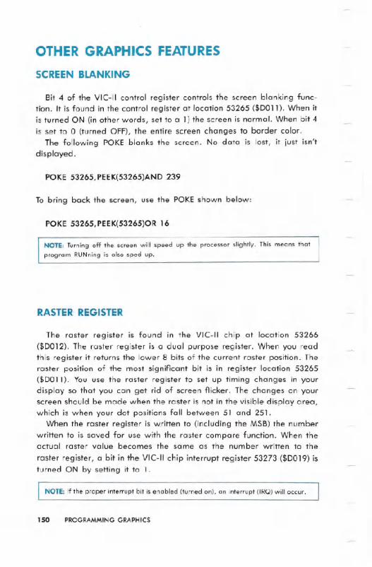
OTHER GRAPHICS FEATURES
SCREEN BLANKING
Bit 4 of the VIC-II control register controls the screen blanking func-tion. It is found in the control register at location 53265 ($D011). When itis turned ON (in other words, set to a 1) the screen is normal. When bit 4is set to 0 (turned OFF), the entire screen changes to border color.
The following POKE blanks the screen. No data is lost, it just isn'tdisplayed.
"POKE53265,PEEK(53265)AND 239
To bring back the screen, use the POKE shown below:
POKE 53265,PEEK(53265)OR 16
NOTE: Turning off the screen will speed up the processor slightly. This means that
program RUNning is also sped up.
RASTER REGISTER
The raster register is found in the VIC-II chip at location 53266($DOI2). The raster register is a dual purpose register. When you readthis register it returns the lower 8 bits of the current raster position. Theraster position of the most significant bit is in register location 53265($D011). You use the raster register to set up timing changes in yourdisplay so that you can get rid of screen flicker. The changes on yourscreen should be made when the raster is not in the visible display area,which is when your dot positions fall between 51 and 251.
When the raster register is w.ritten to (including the MSB) the numberwritten to is saved for use with the raster compare function. When theactual raster value becomes the same as the number written to the
raster register, a bit in the VIC-II chip interrupt register 53273 ($DO19) isturned ON by setting it to 1.
NOTE: If the proper interrupt bit is enabled (turned on), an interrupt (IRQ) will occur.
150 PROGRAMMING GRAPHICS
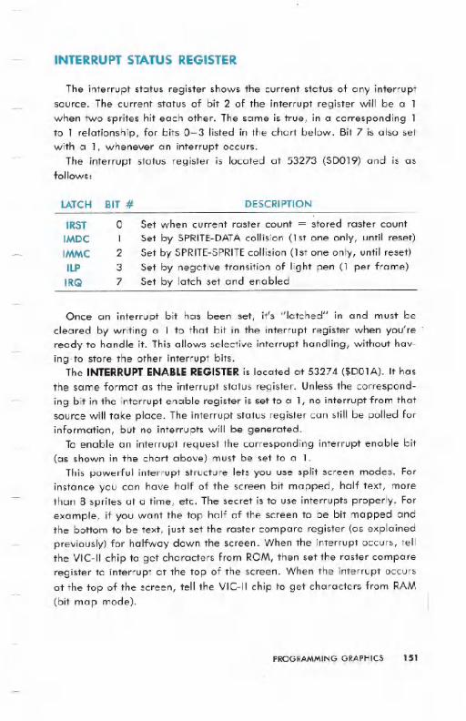
INTERRUPT STATUS REGISTER
The interrupt status register shows the current status of any interruptsource. The current status of bit 2 of the interrupt register will be a 1when two sprites hit each other. The same is true, in a corresponding 1to 1 relationship, for bits 0-3 listed in the chart below. Bit 7 is also setwith aI, whenever an interrupt occurs.
The interrupt status register is located at 53273 ($DOI9) and is asfollows:
BIT # DESCRIPTIONLATCH
IRSTIMDC
IMMC
ILP
IRQ
o Set when current raster count = stored raster count
1 Set by SPRITE-DATAcollision (1st one only, until reset)2 Set by SPRITE-SPRITEcollision (1st one only, until reset)3 Set by negative transition of light pen (1 per frame)7 Set by latch set and enabled
Once an interrupt bit has been set, it's "latched" in and must becleared by writing a 1 to that bit in the. interrupt register when you'reready to handle it. This allows selective interrupt handling, without hav-ing.to store the other interrupt bits.
The INTERRUPTENABLEREGISTERis located at 53274 ($D01A). It has
the same format as the interrupt status register. Unless the correspond-ing bit in the interrupt enable register is set to aI, no interrupt from thatsource will take place. The interrupt status register can still be polled forinformation, but no interrupts will be generated.
To enable an. interrupt request the corresponding interrupt enable bit(as shown in the chart above) must be set to a 1.
This powerful interrupt structure lets you use split screen modes. Forinstance you can have half of the screen bit mapped, half text, morethan 8 sprites at a time, etc. The secret is to use interrupts properly. Forexample, if you want the top half of the screen to be bit mapped andthe bottom to be text, just set the raster compare register (as explainedpreviously) for halfway down the screen. When the interrupt occurs, tellthe VIC-II chip to get characters from ROM, then set the raster compareregister to interrupt at the top of the screen. When the interrupt occursat the top of the screen, tell the VIC-II chip to get characters from RAM(bit map mode).
PROGRAMMING GRAPHICS 151
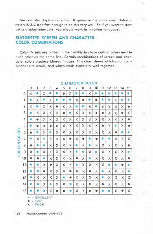
You can also display more than 8 sprites in the same way. Unfortu-nately BASIC isn't fast enough to do this very well. So if you want to startusing display interrupts, you should work in machine language.
SUGGESTEDSCREEN AND CHARACTERCOLOR COMBINATIONS
Color TV sets are limited in their ability to place certain colors next toeach other on the same line. Certain combinations of screen and char-acter colors produce blurred images. This chart shows which color com-binations to avoid, and which work especially well together.
CHARACTER COLORo 1 2 3 4 5 6 7 8 9 10 11 12 13 14 15
o
1
2
3
4
5a:9 68 7
~ 8w~ 9(/)
10
11
12
13
14
15
. = EXCELLENT. = FAIRX = POOR
152 PROGRAMMING GRAPHICS
x . X . . . X . . X . . . . . .. X . X . . . X . . . . . X . .X . X X . X X . . X . X X X X .. X X X X . . X X X X . X X . X
. . X X X X X X X X X X X X X .
. . X . X X X X X X X . X . X .
. . X . X X X X X X X X X . . .
. X . X X X . X . . . . . X X X
. . . X X X X . X . X X X X X .X . X X X X X . . X . X X X X .. . . X X X X . X . X X X X X .. . X . X X X . X X X X . . . .. . . X X X . X X . X . X X X .. X X X X . . X X X X . X X X X. . X . X X . X X X X . X X X .. . . X . . . X X . . . . X . X
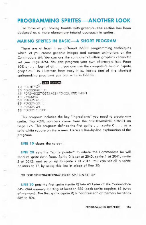
PROGRAMMING SPRITES-ANOTHER LOOKFor those of you having trouble with graphics, this section has been
designed as a more elementary tutorial approach to sprites.
MAKING SPRITES IN BASIC-A SHORT PROGRAM
There are at least three different BASIC programming techniques
which let you create graphic images and cartoon animations on theCommodore 64. You can use the computer's built-in graphics character
set (see Page 376). You can program your own characters (see Page108) or . . . best of all . . . you can use the computer's built-in "spritegraphics." To illustrate how easy it is, here's one of the shortestspritemaking programs you can write in BASIC:
102030405(1607080
AllDramEPR ItH "6' -
POKE2iZ14iZ1.. 13FOF:::;=8:32TO::::32+62 : POKES, 255 : t'~EXT11,"==5:3248
POKEV+21,lPOKE' +:39.. 1POKE'v'.' 24POKE + 1 .' 100
This program includes the key "ingredients" you need to create anysprite. The POKE numbers come from the SPRITEMAKINGCHART onPage 176. This program defines the first sprite . . . sprite 0 . . . as a
solid white square on the screen. Here's a line-by-line explanation of theprogram:
LINE 10 clears the screen.
LINE 20 sets the "sprite pointer" to where the Commodore 64 will
read its sprite data from. Sprite 0 is set at 2040, sprite 1 at 2041, sprite2 at 2042, and so on up to sprite 7 at 2047. You can set all 8 spritepointers to 13 by using this line in place of line 20:
20 FOR SP=2040T02047:POKE SP,13:NEXT SP
LINE 30 puts the first sprite (sprite 0) into 63 bytes of the Commodore
64's RAM memory starting at location 832 (each sprite requires 63 bytes
of memory). The first sprite (sprite 0) is "addressed" at memory locations832 to 894.
PROGRAMMINGGRAPHICS 153

LINE 40 sets the variable "V" equal to 53248, the starting address ofthe VIDEO CHIP. This entry lets us use the form (V+number) for spritesettings. We're using the form (V+number) when POKEing sprite settingsbecause this format conserves memory and lets us work with smallernumbers. For example, in line 50 we typed POKEV+21. This is the sameas typing POKE 53248+21 or POKE 53269 . . . but V+21 requires less
space than 53269, and is easier to remember.
LINE 50 enables or "turns on" sprite o. There are 8 sprites, numberedfrom 0 to 7. To turn on an individual sprite, or a combination of sprites,all you have to do is POKE V+21 followed by a number from 0 (turn allsprites off) to 255 (turn all 8 sprites on). You can turn on one or moresprites by POKEing the following numbers:
POKE V+21, 1 turns on sprite O. POKEV+21, 128 turns on sprite 7. Youcan also turn on combinations of sprites. For example, POKE V+21, 129turns on both sprite 0 and sprite 7 by adding the two "turn on" numbers(1+128) together. (See SPRITEMAKINGCHART, Page 176.)
LINE 60 sets the COLOR of sprite O. There are 16 possible spritecolors, numbered from 0 (black) to 15 (grey). Each sprite requires adifferent POKE to set its color, from V+39 to V+46. POKE V+39,1colors sprite 0 white. POKE V+46,15 colors sprite 7 grey. (See theSPRITEMAKINGCHART for more information.)
When you create a sprite, as you just did, the sprite will STAY INMEMORY until you POKE it off, redefine it, or turn off your computer.This lets you change the color, position and even shape of the sprite inDIRECTor IMMEDIATEmode, which is useful for editing purposes. As anexample, RUN the program above, then type this line in DIRECTmode(without a line number) and hit the .:~alll:U. key:
POKE V+39,8
The sprite on the screen is now ORANGE. Try POKEing some other num-bers from 0 to 15 to see the other sprite colors. Because you did this inDIRECTmode, if you RUNyour program the sprite will return to its origi-nal color (white).
154 PROGRAMMING GRAPHICS
LINE 70 determines the HORIZONTALor "X" POSITION of the spriteon the screen. This number represents the location of the UPPER LEFTCORNER of the sprite. The farthest left horizontal (X) position which youcan see on your television screen is position number 24, although youcan move the sprite OFF THE SCREENto position number O.
LINE 80 determines the VERTICALor "Y" POSITION of thE:'sprite. Inthis program, we placed the sprite at X (horizontal) position 24, and Y(vertical) position 100. To try another location, type this POKE in DIRECTmode and hit _t~:llIlt~/_:
POKE V,24:POKE V+l,50
This places the sprite at the upper left corner of the screen. To move thesprite to the lower left corner, type this:
POKE V,24:POKE V+l,229
Each number from 832 to 895 in our sprite 0 address represents oneblock of 8 pixels, with three 8-pixel blocks in each horizontal row of thesprite. The loop in line 80 tells the computer to POKE 832,255 whichmakes the first 8 pixels solid. . . then POKE 833,255 to make the second8 pixels solid, and so on to location 894 which is the last group of 8pixels in the bottom right corner of the sprite. To better see how thisworks, try typing the following in DIRECT mode, and notice that thesecond group of 8 pixels is erased:
POKE 833,0 (to put it back type POKE 833,255 or RUN your program)
The following line, which you can add to your program, erases theblocks in the MIDDLEof the sprite you created:
90 FOR A=836 TO 891 STEP 3:POKE A,O:NEXTA
Remember, the pixels that make up the sprite are grouped in blocks ofeight. This line erases the 5th group of eight pixels (block 836) and everythird block up to block 890. Try POKEing any of the other numbers from832 to 894 with either a 255 to make them solid or 0 to make themblank.
PROGRAMMING GRAPHICS 155
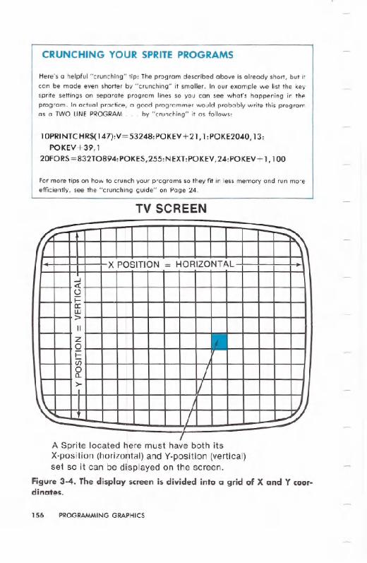
CRUNCHING YOUR SPRITE PROGRAMS
Here's a helpful "crunching" tip: The program described above is already short, but it
can be made even shorter by "crunching" it smaller. In our example we list the key
sprite settings on separate program lines so you can see what's happening in the
program. In actual practice, a good programmer would probably write this programas a TWO LINE PROGRAM. . . by "crunching" it as follows:
10PRINTCHR$(147):V=53248:POKEV+21, 1:POKE2040, 13:POKEV+39,1
20FORS =832T0894: POKES,255:NEXT:POKEV,24: POKEY+ 1,100
For more tips on how to crunch your programs so they fit in less memory and run more
efficiently, see the "crunching guide" on Page 24.
TV SCREEN
A Sprite located here must have both itsX-position (horizontal) and V-position (vertical)set so it can be displayed on the screen.
Figure 3-4. The display screen is divided into a grid of X and Y coor-dinates.
156 PROGRAMMING GRAPHICS
!IA \X POSITION = HORIZONTAL
...J«()
a:w>II
Z0
Ci50 /a.>- /
I/

POSITIONING SPRITES ON THE SCREEN
The entire display screen is divided into a grid of X and Y coordi-nates, like a graph. The X COORDINATE is the HORIZONTALpositionacross the screen and the Y COORDINATEis the VERTICALposition upand down (see Figure 3-4).
To position any sprite on the screen, you must POKE TWO SETTINGS. . . the X position and the Y position .. . these tell the computer where
to display the UPPER LEFTHAND CORNER of the sprite. Remember thata sprite consists of 504 individual pixels, 24 across by 21 down. . . so ifyou POKE a sprite onto the upper left corner of your screen, the spritewill be displayed as a graphic image 24 pixels ACROSS and 21 pixelsDOWN starting at the X-V position you defined. The sprite will be dis-played based on the upper left corner of the entire sprite, even if youdefine the sprite using only a small part of the 24X21-pixel sprite area.
To understand how X-Y positioning works, study the following dia-gram (Figure 3-5), which shows the X and Y numbers in relation to yourdisplay screen. Note that the GREY AREA in the diagram shows yourtelevision viewing area . . . the white area represents positions whichare OFF your viewing screen. . .
0--
50 -
::oa:u.Zit)=>",a:C\I(/)0ZI-
~t
o 24:~1
X POSITIONS RUN FROM 0 TO 255,THEN YOU MUST POKE V+16, 1 255
AND START OVER AT 0 TO 91 b' 'J1I .
X =255. Y = 50 I POKE V+16, 1 AND
\ 1 X =65, Y =50
X =231, Y = 50 ': \ I
I
i
: x = 24,Y = 50
:/
II
VIEWINGSCREENAREAIIIIIII
x =24, Y =229 X = 229, Y = 231 I
x = 24, Y =250 POKE V+16, 1 ANDX = 65,Y =229
Figure 3-5. Determining X-V sprite. positions.
PROGRAMMINGGRAPHICS 157

To display a sprite in a given location, you must POKE the X and Ysettings for each SPRITE . . . remembering that every sprite has its ownunique X POKE and Y POKE. The X and Y settings for all 8 sprites areshown here:
POKE THESE VAWES TO SET.X-Y SPRITE POSITIONS
POKEING AN X POSITION: The possible values of X are 0 to 255,counting from left to right. Values 0 to 23 place all or part of the spriteOUT OF THE VIEWINGAREAoff the left side of the screen. . . values 24
to 255 place the sprite IN THE VIEWING AREA up to the 255th position(see next paragraph for settings beyond the 255th X position). To placethe sprite at one of these positions, just type the X-POSITION POKE forthe sprite you're using. For example, to POKE sprite 1 at the farthest leftX position IN THE VIEWING AREA, type: POKE V+2,24.
X VALUESBEYOND THE 255TH POSIT10N: To get beyond the 255thposition across the screen, you need to make a SECOND POKEusing thenumbers in the "RIGHT X" row of the chart (Figure 3-5). Normally, thehorizontal (X) numbering would continue past the 255th position to 256,257, etc., but because registers only contain 8 bits we must use a "sec-ond register" to access the RIGHT SIDE of the screen and start our Xnumbering over again at O. So to get beyond X position 255, you mustPOKE V+ 16 and a number (depending on the sprite). This gives you 65additional X positions (renumbered from 0 to 65) in the viewing area onthe RIGHT side of the viewing screen. (You can actually POKE the rightside X value as high as 255, which takes you off the right edge of theviewing screen.)
POKEING A Y POSITION: The possible values of Yare 0 to 255, count-ing from top to bottom. Values 0 to 49 place all or part of the sprite OUTOF THEVIEWINGAREAoff the TOP of the screen. Values 50 to 229 placethe sprite IN THE VIEWING AREA. Values 230 to 255 place all or part ofthe sprite OUT OF THE VIEWING AREA off the BOTTOM of the screen.
158 PROGRAMMING GRAPHICS
SPRITEO SPRlTE1 SPRlTE2 SPRlTE3 SPRITE4 SPRITES SPRlTE6 SPRlTE7
SETX v,x V+2,X V+4,X V+6,X V+8,X V+10,X V+12,X V+14,X
SETY V+l,Y V+3,Y V+S,Y V+7,Y V+9,Y V+l1,Y V+13,Y V+1S,Y
RIGHTX V+16,1 V+16,2 V+16,4 V+16,8 V+16,16 V+16,32 V+16,64 V+16,128

let's see how this X-V positioning works, using sprite 1. Type this pro-gram:
-'!mil G!DD10 PRINT"~~3248:POKEV+21.2:POKE2041.13:FOP::;=832T0895 :POKES, 255 :t.jE:'<T
20 POKE' +41;):, 7
3(1 POKEV+2., 24
4(1 POKEV+3, 50
This simple program establishes sprite 1 as a solid box and positions itat the upper left corner of the screen. Now chclnge line 40 to read:
40 POKE V+3,229
This moves the sprite to the bottom left corner of the screen. Now let'stest the RIGHTX LIMITof the sprite. Change line 30 as shown:
30 POKE V+2,255
This moves the sprite to the RIGHTbut reaches the RIGHTX LIMIT,whichis 255. At this point, the "most significant bit" in register 16 must be SET.In other words, you must type POKEV+16 and the number shown in the"RIGHT X" column in the X-Y POKE CHART above to RESTARTthe Xposition counter at the 256th pixel/position on the screen. Change line 30as follows:
30 POKE V+16, PEEK(V+16)OR 2:POKE V+2,0
POKEV+ 16,2 sets the most'significant bit of the X position for sprite 1and restarts it at the 256th pixel/position on the screen. POKE V+2,Odisplays the sprite at the NEW POSITION ZERO, which is now reset to the256th pixel.
To get back to the left side of the screen, you must reset the mostsignificant bit of the X position counter to 0 by typing (for sprite 1):
POKE V+16, PEEK(V+16)AND 253
TO SUMMARIZE how theX positioning works . . . POKEthe X POSI-TION for any sprite with a number from 0 to 255. To access a positionbeyond the 255th position/pixel across the screen, you must use an ad-ditional POKE(V+ 16) which sets the most significant bit of the X positionand start counting from 0 again at the 256th pixel across the screen.
PROGRAMMINGGRAPHICS 159

This 'POKEstarts the X numbering over again from 0 at the 256th posi-tion (Example: POKE V+16, PEEK(V+16)OR 1 and POKE V,1 must beincluded to place sprite 0 at the 257th pixel across the screen.) To getback -to the left side X positions you have to TURNOFFthe control settingby typing 'POKE V+'16, PEEK(V+16)AND 254.
POSITIONING MUIIIPLE SPRITES ON THE SCREEN
Here's a program which defines THREE:DIFFERENTSPRITES(0, 1, and2) in different colors .and places them in different positions .on thescreen:
...raI!tJ!n10 PRI NT":i"~53248 : FORS=.832T0895 : POKES, 255 : t.jEXT2121FORt1=2040T02042 :'POKEM, .13 ::NE:><:T3(1 POKEV+21.,740 POKEV+.39,l: POKEV+4iZ1.,7 :P.OKEV+41, 850 POKEV,24:POKEV+l,50,513 POKEV+2., .12 : POKEV+3., 22970 POKEV+4,255:POKEV+5,50
For convenience, all 3 sprites have been defined as solid squares,getting their data from. the same place. The 'important lesson here ishow the 3 sprites are positioned. The white .sprite 0 is ot the. top lefthandcorner. The.yellow sprite 1 is at the bottom lefthand corner but'HALF thesprite is OFF THE SCREEN(remember, 24 is the leftmost X position in theviewing area. . . an X position less than 24 puts 'oll'or part of the sprite'off the screen and we .used an X position 12 here which put the s.pritehalfway off.the screen). Finally, the orange sprite 2 is at the RIGHT XLIMIT (position 255) . . . but what if you want to display a sprite in thearea to .the RIGHT of X position 255?
DISPLAYINGA SPRITE BEYOND THE 255TH X-POSITION
Displaying a sprite beyond the 255th X position requires a specialPOKEwhich SETSthe .most significant 'bit of the X position and starts overat the 256th pixel position across the screen. Here's how it works. . .
First, you POKE V+ 16 with the number for :the sprite you're using(check the "RIGHT X" row in the X-Y chart. . . we'll use sprite 0). Nowwe assign an X position, keeping in mind that the X counter starts .over
from 0 at the 256th position on the screen. Change line 50 to read asfollows:
50 POKEV+16,1:POKE V,24:POKE V+l,75
1-60 :PROGRAMMING GRAPHICS
This line POKEs V+16 with the number required to "open up" the right
side of the screen. . .the new X position 24 for sprite 0 now begins 24
pixels to the RIGHT of position 255. To check the right edge of thescreen, change line 60 to:
60 POKE V+16,1:POKE V,65:POKE V+l,75
Some experimentation with the settings in the sprite chart will give youthe settings you need to position and move sprites on the left and rightsides of the screen. The section on "moving sprites" will also increaseyour understanding of how sprite positioning works.
SPRITE PRIORITIES
You can actually make different sprites seem to move IN FRONT OF orBEHINDeach other on the screen. This incredible three dimensional illu-
sion is achieved by the built-in SPRITEPRIORITIESwhich determine whichsprites have priority over the others when 2 or more sprites OVERLAPonthe screen.
The rule is "first come, first served" which means lower-numbered
sprites AUTOMATICALLYhave priority over higher-numbered sprites. Forexample, if you display sprite 0 and sprite 1 so they overlap on thescreen, sprite 0 will appear to be IN FRONT OF sprite 1. Actually, spriteo always supersedes all the other sprites because it's the lowest num-bered sprite. In comparison, sprite 1 has priority over sprites 2-7; sprite2 has priority over sprites 3-7, etc. Sprite 7 (the last sprite) has LESSPRIORITYthan any of the other sprites, and will always appear to bedisplayed "BEHIND" any other sprites which overlap its position.
To illustrate how priorities work, change lines 50, 60, and 70 in theprogram above to the following:
182031Z1485121687121
~ I"'~.":I'IM:II .. II' _C:"'-' . ~_r'.'-t'-' C:-. f!"'. '-,IC:'!:':'. ...P~INT. .V-~3,48.FOR~-o~,T089~.POKE~,~~~.NE0T
FORt1=2048T02042 : POKEM, 13: t.1E:>I,T.POKEV+21,7POKEV+39,1:POKEV+40,7:POKEV+41,8POKEV., 24 : POKEV+ 1 , 5121: pm~E',...+16., (IPOKEV+2.34:POKEV+3,60POKEV+4,44:PC~EV+5,70
You should see a white sprite on top of a yellow sprite on top of an
orangesprite. Of course, now that you see how priorities work, you canalso MOVE SPRITESand take advantage of these priorities in your ani-mation.
PROGRAMMING GRAPHICS 161
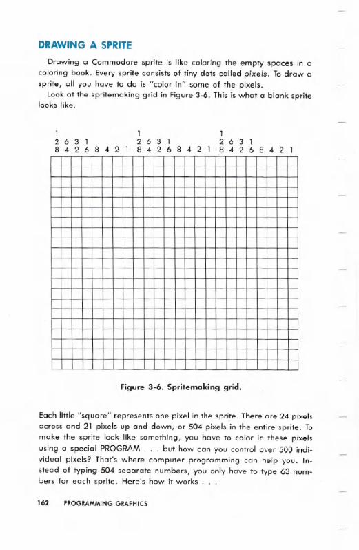
DRAWING A SPRITE
Drawing a Commodore sprite is like coloring the empty spaces in acoloring book. Every sprite consists of tiny dots called pixels. To draw asprite, all you have to do is "color in" some of the pixels.
Look at the spritemaking grid in Figure 3-6. This is what a blank spritelooks like:
163126314 2 6 842 1 8 4 2 6 842 1
1263 18 4 2 6 8 4 2 1
Figure 3-6. Spritemaking grid.
Each little "square" represents one pixel in the sprite. There are 24 pixelsacross and 21 pixels up and down, or 504 pixels in the entire sprite. Tomake the sprite look like something, you have to color in these pixelsusing a special PROGRAM . . . but how can you control over 500 indi-vidual pixels? That's where computer programming can help you. In-stead of typing 504 separate numbers, you only have to type 63 num-bers for each sprite. Here's how it works .
162 PROGRAMMING GRAPHICS

CREATING A SPRITE . . . STEP BY STEP
To make this as easy as possible for you, we've put together thissimple step by step guide to help you draw your own sprites.
STEP 1:
Write the spritemaking program shown here ON A PIECEOF PAPER.note that line 100 starts a special DATAsection of your program whichwill contain the 63 numbers you need to create your sprite.
~m:mm10 PR HIT":1" : POKE53;,80, 5 : POKE53281 , 620 V=53248:POKEV+34,330 POKE53269,4:POKE2042,1340 FORH=(;H062: READQ: POKE':'32+t.l.. Q : t.jEXT
100 DATA255,255,2551'211 DATAI28,0..1102 DATAI28..0.. 1103 DRTAI28, 0..11(14 DATAI44.0.1-105 Dt1TI"I144..0..1-106 DATAI44,0,1-107 DRTI"I144..0, 1-108 DATAI44,0,1-109 DATAI44,O,I-110 DATAI44,Q,1-111 DATAI44,0,1-112 DATAI44,0,1-113 DATAI44..(I, 1-114 DATAI28, 0..1-115 DATAI28, 0..1-116 DATAI28,O,I-117 DATA128, 0.. 1-11:3 DATA128..0..1-119 DATAI28,0,1-12121DATA255., 255., 255:2(10 :.<:=200: 'T'=1(1(1: POKE53252.. :":: POKE53253.. 'r'
STEP 2:
Color in the pixels on the spritemaking grid on Page 162 (or use a pieceof graph paper. . . remember, a sprite has 24 squares across and 21squares down). We suggest you use a pencil and draw lightly so you canreuse this grid. You can create any image you like, but for our examplewe'll draw a simple box.
STEP 3:
look at the first EIGHTpixels. Each column of pixels has a number (128,64, 32, 16, 8, 4, 2, 1). The special type of addition we are going toshow you is a type of BINARYARITHMETICwhich is used by most com-
PROGRAMMING GRAPHICS 163
2664 32 16 6 4 2 , 12864 32 16' 8 4 2 , 12864 32 '6 6 4 2 ,
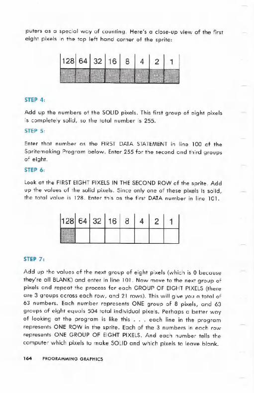
puters as a special way of counting. Here's a close-up view of the first
eight pixels in the top left hand corner of the sprite:
STEP4:
Add up the numbers of the SOLID pixels. This first group of eight pixelsis completely solid, so the total number is 255.
STEP5:
Enter that number as the FIRST DATA STATEMENTin line 100 of the
Spritemaking Program below. Enter 255 for the second and third groupsof eight.
STEP6:
Look at the FIRSTEIGHT PIXELSIN THE SECOND ROW of the sprite. Addup the values of the solid pixels. Since only one of these pixels is solid,the total value is 128. Enter this as the first DATAnumber in line 101.
1618 4 2 1
STEP7:
Add up the values of the next group of eight pixels (which is 0 because
they're all BLANK)and enter in line 101. Now move to the next group ofpixels and repeat the process for each GROUPOF EIGHTPIXELS(thereare 3 groups across each row, and 21 rows). This will give you a total of63 numbers. Each number represents ONE group of 8 pixels, and 63groups of eight equals 504 total individual pixels. Perhaps a better wayof looking at the program is like this . . . each line in the programrepresents ONE ROW in the sprite. Each of the 3 numbers in each rowrepresents ONE GROUP OF EIGHT PIXELS. And each number tells the
computer which pixels to make SOLID and which pixels to leave blank.
164 PROGRAMMING GRAPHICS

STEP 8:
CRUNCH YOUR PROGRAM INTO A SMALLER SPACE BY RUNNING TO-
GETHER ALL THE DATA'STATEMENTS, AS SHOWN IN THE SAMPLE PRO-
GRAM BELOW. Note that we asked you to write your sprite program ona piece of paper. We did this for a good reason. The DATA STATEMENT
LINES 100- 120 in. the program. in STEP 1 are only thereto help you. seewhich numbers relate to which 'groups of pixels in your sprite. Your finalprogram should be "crunched" like this:
~S!iImm1121"PRHlT":J" :'POI<E53280, 5: POKE53281., 62(1 V=5::::24:3: POKEV+34,. 330 POKE53269., 4 : POKE2042, 134121FOF.:I'I=0T062: READQ : POKE832+t.j, Q : NEi':T100 DATA255,255,255,128,(I,1,128,0,1,128,O.I,144,(I,1,144,0,1..144,0,1,144,(1,1101 DATAL44,0,1,144~0,1,144,O,1,144,e,I,144,0,1,144, 0., 1 .' 12:::., (I, L 128, 0, 111212DI=tTAI28, 10,1.,128.,121,1,128.,.(1,1.,128.. e.. 1..255.. 255, 25~l20tt ;<:=200: ITI=100 : POI<E53252., :x:: POKE53253., IT'
MOVING YOUR SPRITE ON THE SCREEN
Now that you've created your sprite, let's do some interesting things.with it. To move your sprite: smoothly across the screen, add these two
lines' to your program:
50 POKE V+5,100:FOR X=24T0255:POKE V+4,X:NEXT:POKEV+16,4'
55 FOR X=OT065:POKE V+4,X:NEXT X:POKE V+ 16,0:GOTO 50
LINE 50 POKEs the. Y POSITION at 100 (try 50 or 229 instead forvariety). Then it sets up a FOR . . . NEXT loop which POKEs the sprite
into X position 0 to X position 255, in order. When it reaches the 255th
position, it POKEs the RIGHT X POSITION (POKE V+ 16,4) which is re-quired to'cross to' the riglit.side of the s<:reen.
LINE55 hasa FOR. . . NEXTloop which continues to POKEthe spritein. the last 65 positions on the screen. Note that the X value was reset tozero but because you. used the RIGHT X setting (POKE V+ 16,2) X startsover on the right side of the screen.
This line keeps going back to itself (GOTO 50).. If you just. want thesprite to' move ONCE' across the screen and disappear, then take. outGOT050.
PROGRAMMINGGRAPHICS 165.
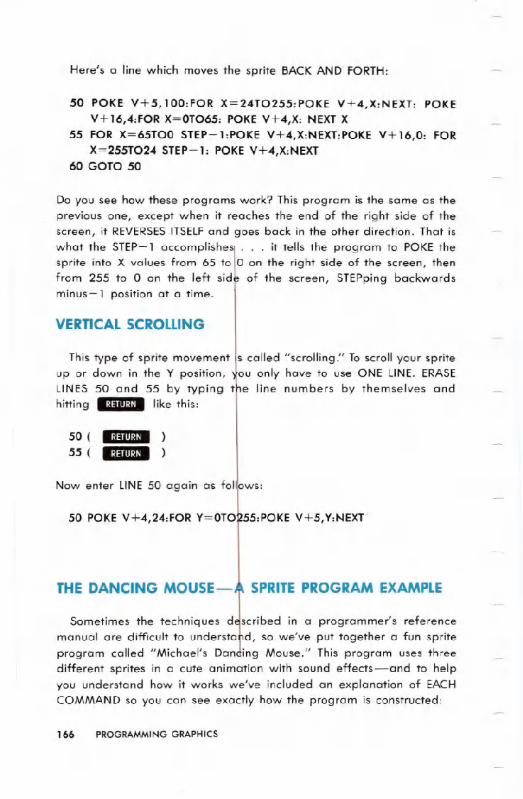
,Here's a line which moves the sprite BACKAND FORTH:
50 POKE V+5,100:FOR X=24T0255:POKE V+4,X:NEXT: POKEV+16,4:FOR X=OT065: POKE V+4,X: NEXT X
55 FOR X=65TOO STEP-l:POKE V+4,X:NEXT:POKE V+16,O: FORX=255T024 STEP-l: POKE V+4,X:NEXT
60 GOTO 50
Do you see how these programs work? This program is the same as theprevious one, except when it reaches the end of the right side of thescreen, it REVERSES.ITSELFand goes back in the other direction. That iswhat the STEP-l accomPlishe
~
. . . it tells the program to POKE thesprite into X values from 65 to 0 on the right side of the screen, thenfrom 255 to 0 on the left sid of the screen, STEPping backwardsminus-l position at a time.
VERTICAL SCROLLING
This type of sprite movement
tcalled "scrolling." To scroll your sprite
up or down in the Y position, 'ou only have to use ONE LINE. ERASELINES 50 and 55 by typing t e line numbers by themselves andhitting .:l:IIII~~I. like this:
50 (
55 (
Now enter LINE50 again as follOws:
50 POKE V+4,24:FOR Y=OT0I255:POKE V+5,Y:NEXT'
THE DANCING MOUSE-A SPRITE PROGRAM EXAMPLE
Sometimes the techniques d
!Cribed in a programmer's reference
manual are difficult to understa d, so we've put together a fun spriteprogram called "Michael's Dan ing Mouse." This program uses threedifferent sprites in a cute animation with sound effects-and to helpyou understand how it works we've included an explanation of EACHCOMMAND so you can see exactly how the program is constructed:
166 PROGRAMMING GRAPHICS
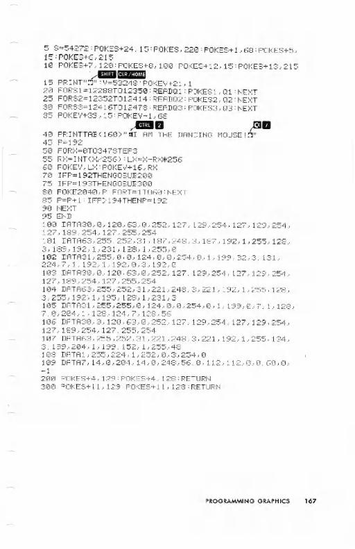
5 8=54272: POKES+24~, 15: POKES., 22121: POKES+ 1.-68 : POKES+5,15:POKES+6,2151121POKES+7,120:POKES+8,100:POKES+12,15:POKES+13,215
'~III.~.":I.h'JI:I
15 PRIHT":J": V=53248: POKEV+2L 12~ZI FORS 1 =12288TO 1235121 : READQ 1 : POKES 1 , Q1 : HE:":T
25 FORS2= 12352TO 12414 : F.:EAD02: POKES2., 02 : t.JE:":T30 FORS3=12416TOI2478:READQ3:POKES3,Q3:HEXT35 POKEV+39,15:POKEV+l,68
,,&lIB40 PF.:IHTTAB (16(1) "=11 At-! THE45 P=1925121FORX=I2IT0347STEP355 RX=INT(X/256):LX=X-RX*25660 POKE V, U<:: POKEV+ 16, f;:>~7(1 I FP= 192THE~JG08U:E:20075 IFP=193THEHGOSUB31211218121POKE204e,p:FORT=1T06121:HE>~:35 P=P+l:IFP>194THENP=1929121HE:":T95 EHD1121121DATi''I:3(1.-er, 12121.,63.- (I.- 252., 127, 129., 254., 127.- 129, 254,
DAtJC UJO t1iU I'''E;6Ia
- -"-' ! ~II
127~189~254~127~255J254101 DATA63,255,252,31,187J248J3,187,192Jl,255J128,3,189,192,1,231,128,1,255,121102 DATA31,255,O,0,124,0,0,254,0,1.199.32.3.131.224,7,1,192.1.192,0,3,192,121103 DATA30,12I. 12121,63.0,252,127,129,254,127, 129,254127J189J254J127J255.. 25411214 DATA63,255,252,31,221,248,3,221~192,1,255,128,3J255J192~1}195J128}lJ231J3105 DATA31)255J255)0)124)0)0)254~0)lJ199J0J7J1J128J7,0,21214,1.128,124,7,128,56106 DATA30,0.12121,63~0,252,127,129,254.127,129,254.127)189)254)127)255)254107 DATA63,255,252,31,221,248.3,221,192,1,255,134.3,189,204,1,199,152~1,255,48108 DATI'=!1 .255., 22"1., 1 .-252., 0., 3., 254., 0109 DATA7,14,0,204,14,O,248,56,0,112,112,O,O.60,O.-120121 POKES+4,129:POKES+4, 128:RETURN31210 POKE8+11 , 129:POKES+l1. 128:RETURN
PROGRAMMING GRAPHICS 167
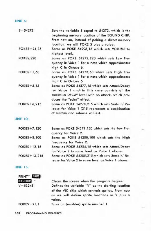
LINE 5:
5=54272
POKES+24, 15'
POKES,220
POKES+ 1,68
POKES+5,15
POKES+6~215
LINE' 10:
POKES+7,120
POKES+8,100
POKES+12,15
POKES'+13,2l5
LINE 15:
PRINT" Emil'1...~.j:I.]fll:l II
V=53248
POKfV+2l,1
Sets the variable 5 equal to 54272, which is thebeginning memory location of the SOUND CH1P.From now on, instead of poking a direct memorylocation, we will POKE 5 plus a value..Same, as POKE '54296,1-5 which sets VOLUME'tohighest leveL.Same as POKE- 54272,220 which sets Low Fre-
quency in Voice 1"for a note which approximates'high'C in Octave' 6.Same as POKE.54273~68' which sets High Fre'"quencyin Voice 1 for a. note: which approximateshigh- C. in Octave 6;Same as POKE 54277,15 which sets Attack/Decayfor Voice 1 and; in thi~ 'case co,nsists of the
maximum DECAYlevel' with no attack, which' pro'" .duces the "echo"'effect.Same as POKE 54278,21S'which sets' Sustain/ Re-lease. for Voice 1 (21"5 represents a combinationof sustain and release values). .
Same as POKE 54279, 120'which sets the-Low Fre-quency for Voice 2.Same as POKE 54280,100 which se1s the HighFrequency' for Voice .2.Same as POKE 54284,15 which sets Attack/Decayfor Voice 2 to same level .as Voice 1 above.Same' as POKE 54285;215,which sets Sustain/ Re-lease for Voice 2 to same level as Voice 1 above.
Clears the screen when the program begins.
Defines the variable "v" as the starting location
of the VIC chip which controls sprites. From now
on we will define sprite locations as V plus avalue.
Turns on (enables)' sprite number 1.
168 PROGRAMMING GRAPHICS

LINE 20:
FORS 1= 12288
TO 12350
READ Q 1
POKES1,Q1
NEXT
We are going to use ONE SPRITE(sprite 0) in thisanimation, but we are going to use THREEsets ofsprite data to define three separate shapes. Toget our animation, we will switch the POINTERSfor sprite ° to the three places in memory wherewe have stored the data which defines our three
different shapes. The same sprite will be rede-fined rapidly over and over again as 3 differentshapes to produce the dancing mouse animation.You can define dozens of sprite shapes in DATASTATEMENTS,and rotate those shapes throughone or more sprites. So you see, you don't have tolimit one sprite to one shape or vice-versa. Onesprite can have many different shapes, simply bychanging the POINTER SETTING FOR THATSPRITE to different places in memory where thesprite data for different shapes is stored. Thisline means we have put the DATA for "spriteshape 1" at memory locations 12288 to 12350.
Reads 63 numbers in order from the DATAstate-
ments which begin at line 100. Q1 is an arbitraryvariable name. It could just as easily be A, Z1 oranother numeric variable.
Pokes the first number from the DATA statements
(the first "Q1" is 30) into the first memory location(the first memory location is 12288). This is thesame as POKE12288,30.
This tells the computer to look BETWEENthe FORand NEXT parts of the loop and perform thosein-between commands (READQ1 and POKES1,Q1
using the NEXTnumbers in order). In other words,the NEXTstatement makes the computer READtheNEXTQ1 from the DATASTATEMENTS,which is 0,and also increments S1 by 1 to the next value,which is 12289. The result is POKE12289,0 . . .the NEXT command makes the loop keep goingback until the last values in the series, which arePOKE 12350,0.
PROGRAMMINGGRAPHICS 169
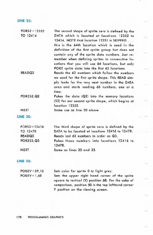
LINE 25:
FORS2 = 12352
TO 12414
READQ2
POKES2,Q2
NEXT
LINE 30:
FORS3= 12416TO 12478READQ3POKES3,Q3
NEXT
LINE 35:
POKEV+39,15POKEV+ 1,68
The second shape of sprite zero is defined by theDATA which is located at locations 12352 to12414. NOTE that location 12351 is SKIPPED. . .this is the 64th location which is used in the
definition of the first sprite group but does notcontain any of the sprite data numbers. Just re-member when defining sprites in consecutive lo-cations that you will use 64 locations, but onlyPOKE sprite data into the first 63 locations.Reads the 63 numbers which follow the numbers
we used for the first sprite shape. This READsim-ply looks for the very next number in the DATAarea and starts reading 63 numbers, one at atime.
Pokes the data (Q2) into the memory locations(52) for our second sprite shape, which begins atlocation 12352.Same use as line 20 above.
The third shape of sprite zero is defined by theDATAto be located at locations 12416 to 12478.
Reads last 63 numbers in order as Q3.Pokes those numbers into locations 12416 to12478.Same as lines 20 and 25.
Sets color for sprite 0 to light grey.Sets the upper right hand corner of the spritesquare to vertical (Y) position 68. For the sake ofcomparison, position 50 is the top lefthand cornerY position on the viewing screen.
170 PROGRAMMING GRAPHICS

LINE 40:
PRINTTAB(160)
I AM THEDANCINGMOUSE!
mil"
LINE 45:
P= 192
LINE 50:
FORX=OT0347STEP3
Tabs 160 spaces from the top lefthand CHAR-ACTERSPACE on the screen, which is the same as4 rows beneath the clear command. . . this starts
your PRINT message on the 6th line down on thescreen.
Hold down the B8 key and press the keymarked 11II at the same time. If you do thisinside quotation marks, a "reversed E" will ap-pear. This sets the color to everything PRINTedfrom then on to WHITE.
This is a simple PRINT statement.
This sets the color back to light blue when thePRINT statement ends. Holding down m and
II at the same time inside quotation markscauses a "reversed diamond symbol" to appear.
Sets the variable P equal to 192. This number 192is the pointer you must use, in this case to "point"sprite 0 to the memory locations that begin at lo-cation 12288. Changing this pointer to the loca-tions of the other two sprite shapes is the secret ofusing one sprite to create an animation that isactually three different shapes.
Steps the movement of your sprite 3 X positions ata time (to provide fast movement) from position 0to position 347.
PROGRAMMING GRAPHICS 171

LINE 55:
RX=INT(X/256)
LX=X-RX*256
LINE 60:
POKEV,LX
POKEV+16,RX
LINE 70:
IFP= 192THEN
GOSUB200
RXis the integer of X/256 which means that RXisrounded off to 0 when X is less than 256, and RXbecomes 1 when X reaches position 256. We willuse RXin a moment to POKE V+16 with a 0 or 1to turn on the "RIGHT SIDE" of the screen.
When the sprite is at X position 0, the formulalooks like this: LX= 0 - (0 times 256) or o. Whenthe sprite is at X position 1 the formula looks likethis: LX= 1 - (0 times 256) or 1. When the spriteis at X position 256 the formula looks like this: LX= 256 - (1 times 256) or 0 which resets X back too which must be done when you start over on theRIGHT SIDEof the screen (POKEV+16,1).
You POKE V by itself with a value to set the Hori-zontal (X) Position of sprite 0 on the screen. (SeeSPRITEMAKING CHART on Page 176). As shownabove, the value of LX, which is the horizontal
position of the sprite, changes from 0 to 255 andwhen it reaches 255 it automatically resets backto zero because of the LXequation set up in line55.
POKEV+16 always turns on the "right side" ofthe screen beyond position 256, and resets thehorizontal positioning coordinates to zero. RX iseither a 0 or a 1 based on the position of thesprite as determined by the RXformula in line 55.
If the sprite pointer is set to 192 (the first spriteshape) the waveform control for the first sound ef-fect is set to 129 and 128 per line 200.
172 PROGRAMMING GRAPHICS

LINE 75:
IFP=193THENGOSUB300
UNE 80:
POKE2040,P
FORT= lT060:NEXT
LINE85:
P=P+1
IFP>194THENP= 192
If the sprite pointer is set to '193 (the secondsprite shape) the waveform control for the secondsound effect (Voice 2) is set to 129 and 128 perline 300.
Sets the SPRITE POINTER to location 1-92 (re-member P=192 in line 451 Here's where we use
the P).A simple time delay loop which sets the speed at.which the mouse dances. (Try a faster or slowerspeed by increasing/decreasing the number t>0.)
Nowwe increase the value,of the pointer by add-ing 1 'to the original value ofP.We only w.ant to point the sprite YO3 memory lo-cations. '192 points to locations 1"2288 to ,12350,193 points to locatio'ns 12352 to 12414, and 194points to locations 12416 to 12478. This line tellsthe computer to reset P back to 192 as ,soon as Pbecomes 195 so P never really becomes 195. P is192, '193, 194 and then resets back to 192 andthe pointer winds up pointing consecutively to thethree sprite shapes in the three 64-byte groups ofmemory locations containing the' DATA.
PROGRAMMING GRAPHICS 173
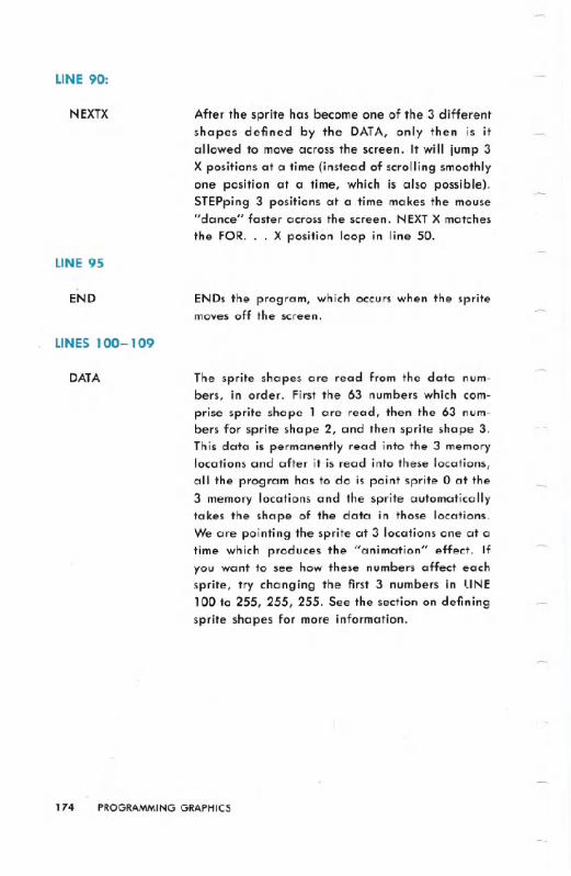
LINE90:
N EXTX
LINE 95
END
LINES100-109
DATA
After the sprite has become one of the 3 differentshapes defined by the DATA, only then is itallowed to move across the screen. It will jump 3X positions at a time (instead of scrolling smoothlyone position at a time, which is also possible).STEPping 3 positions at a time makes the mouse"dance" faster across the screen. NEXTX matches
the FOR. . . X position loop. in line 50.
ENDs the program, which occurs when the spritemoves off the screen.
The sprite shapes are read from the data num-bers, in order. First the 63 numbers which com-prise sprite shape 1 are read, then the 63 num-bers for sprite shape 2, and then sprite shape 3.This data is permanently read into the.3 memorylocations and after it is read into these locations,all the program has to do is point sprite 0 at the3 memory locations and the sprite automaticallytakes the shape of the data in those locations.We are pointing the sprite at 3 locations one at atime which produces the "animation" effect. Ifyou want to see how these numbers affect eachsprite, try changing the first 3 numbers in liNE100 to 255, 255, 255. See the section on definingsprite shapes for more information.
174 PROGRAMMING GRAPHICS

LINE 200:
POKES+4,129
POKES+4,128
RETURN
LINE 300:
POKES+11,129
POKES+ll,128
RETURN
Waveform control set to 129 turns on the soundeffect .Waveform control set to 128 turns off the soundeffect .Sends program back to end of line 70 afterwaveform control settings are changed, to resume
program.
Waveform control set to 129 turns on the sound"effect .Waveform control set to 128 turns off the soundeffect .Sends program back to end of line 75"to resume.
PROGRAMMING GRAPHICS 175
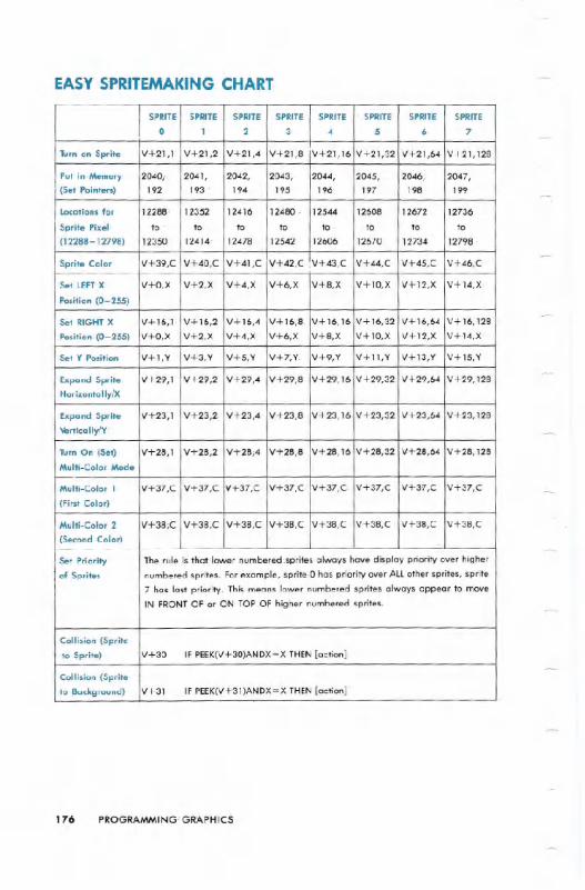
EASY SPR1TEMAKING CHART
176 PROGRAMMING' GRAPHICS
SPRITE SPRITE SPRITE SPRITE SPRITE SPRITE SPRITE SPRITE
0 1 2 3 .. 5 6 7
Turn on Sprite V+21,r V+21,2 V+21,4 V+21,8 V+21,16 V+21,32 V+21,64 V+21,128
Put in.Memory 2040, 2041, 2042, 2043, 2044, 2045, 2046, 2047,
(Set Pointers) 192 193 194 195 196 197 198 199
Locations for 12288. 12352 12416 12480. 12544 12608 12672. 12736
Sprite Pixel to to to to to to to to
(12288-12798) 12350 12414' 1247.8 12542 12606 12670 12734 12798
Sprite Color V+39,C V+40,C V+41,C V+42,C .V+43,C V+44,C V+45,C V+46,C
Set LEFTX V+O,X V+2,X V+4,X V+6,X V+8,X V+10,X V+12,X V+14,X
Position (0-255)
Set RIGHT X V+16,1. V+16,2 V+16,4 V+16,8 V+16,16 V+16,32 V+16,64 V+16,128
Position. (0- 255) V+O,X V+2,X V+4,X' V+6,X V+8,X V+10,X V+12,X V+14,X
Set Y Position V+I,Y V+3,Y V+5,Y V+7;Y. V+9,Y V+I1,Y V+13,Y V+15,Y
Expand Sprite V+29,1 V+29,2 V+29,4 V+29,8 V+29,16 V+29,32 V+29,64 V+29,128
Horizontally/)(
Expand Sprite V+23',1 V+23,2 V+23.4 V+23,8 V+23,16 V+23,32 V+23,64 V+23,128
Vertica lIylY
Tum On (Set) V+28,1 V+28,2 V+28;4 V+28,8 V+28,16 V+28,32 V+28,64 V+28,128
Multi-Color Mode
Multi-Color 1 V+37,C V+37,C V+37;C V+37,C V+37,C. V+37,C V+37,C V+37,C'
(First Color)
Multi-Color 2 V+38;C V+38,C V+38,C V+38,C V+38,C V+38,C V+38,C V+38,C
(Second Color)
Set Priority The rule is that lower numbered '.sprites always have display priority over higher
of Sprites numbered sprites. For example, sprite'O has priority over ALLother sprites, sprite
7 has last priority. This means lower numbered sprites always appearto moveIN FRONT OF or ON TOP OF higher numbered sprites.
Collision (Sprite
to Sprite) V+30 IF PEEK(V+30)ANDX=X THEN [action]
Collision (Sprite
to Background) V+31 IF PEEK(V+31)ANDX=X THEN [action]"
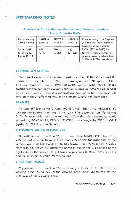
SPRITEMAKING NOTES
Alternative Sprite Memory Pointers and Memory LocationsUsing Cassette Buffer
TURNING ON SPRITES:
You can turn on any individual sprite by using POKE V+21 and the
number from the chart. . . BUT. . . turning on just ONE sprite will turnOFF any others. To turn on TWO OR MORE sprites, ADD TOGETHERthenumbers of the sprites you want to turn on (Example: POKEV+21, 6 turnson sprites 1 and 2). Here is a method you can use to turn one sprite offand on without affecting any of the others (useful for animation).
EXAMPLE:
To turn off just sprite 0 type: POKE V+21,PEEK V+21AND(255-l).Change the number 1 in (255-1) to 1,2,4,8,16,32,64, or 128 (for sprites0-7). To re-enable the sprite and not affect the other sprites currentlyturned on, POKEV+21, PEEK(V+2l)OR 1 and change the OR 1 to OR 2(sprite 2), OR 4 (sprite 3), etc.
X POSITION VALUESBEYOND 255:
X positions run from 0 to 255 . . . and then STARTOVER from 0 to255. To put a sprite beyond X position 255 on the far right side of thescreen, you must first POKE V+ 16 as shown, THEN POKE a new X valuefrom 0 to 63, which will place the sprite in one of the X positions at theright side of the screen. To get back to positions 0-255, POKE V+16,0and POKE in an X value from 0 to 255.
Y POSITION VALUES:
Y positions run from 0 to 255, including 0 to 49 off the TOP of theviewing area, 50 to 229 IN the viewing area, and 230 to 255 off theBOTTOM of the viewing area.
PROGRAMMINGGRAPHICS 177
Put in Memory SPRITE 0 SPRITE 1 SPRITE 2 If you're using 1 to 3 sprites(Set pointers) 2040,13 2041,14 2042,15 you can use these memory
locations in the cassette
Sprite Pixel 832 896 960 buffer (832 to 1023) butLocations for to 894 to 958 to 1022 for more than 3 sprites weBlocks 13-15 suggest using locations from
12288 to 12798 (see chart).

SPRITE COLORS:
To make sprite 0 WHITE, type: POKE V+39,1 (use COLOR POKE SET-TING shown in chart, and INDIVIDUALCOLOR CODES shown below):
0- BLACK1-WHITE2-RED3-CYAN
4-PURPLE5-GREEN6-BLUE7 - YELLOW
8-0RANGE 12-MED. GREY9-BROWN 13-LT. GREEN10-LT. RED 14-LT. BLUE
ll-DARK GREY15-LT. GREY
MEMORY LOCATION:
You must "reserve" a separate 64-BYTE BLOCK of numbers in thecomputer's memory for each sprite of which 63 BYTESwill be used forsprite data. The memory settings shown below are recommended forthe "sprite pointer" settings in the chart above. Each sprite will beunique and you'll have to define it as you wish. To make "all spritesexactly the same, point the sprites you want to look the same to thesame register for sprites.
DIFFERENT SPRITE POINTER SETTINGS:
These sprite pointer settings are RECOMMENDATIONSONLY.Caution: you can set your sprite pointers anywhere in RAM memory
but if you set them too "low" in memory a long BASIC program mayoverwrite your sprite data, or vice versa. To protect an especially LONGBASIC PROGRAM from overwriting sprite data, you may want to set thesprites at a higher area of memory (for example, 2040,192 for sprite 0at locations 12288 to 12350 . . . 2041,193 at locations 12352 to 12414
for sprite 1 and so on . . . by adjusting the memory locations from whichsprites get their "data," you can define as many as 64 different spritesplus a sizable BASIC program. To do this, define several sprite "shapes"in your DATAstatements and then redefine a particular sprite by chang-ing the "pointer" so the sprite you are using is "pointed" at differentareas of memory containing different sprite picture data. See the "Danc-ing Mouse" to see how this works. If you want two or more sprites tohave THE SAME SHAPE (you can still change position and color of eachsprite), use the same sprite pointer and memory location for the spritesyou want to match (for example, you can point sprites 0 and 1 to thesame location by using POKE 2040,192 and POKE 2041, 192).
178 PROGRAMMING GRAPHICS

PRIORITY:
Priority means one sprite will appear to move "in front of" or "behind"
another sprite on the display screen. Sprites with more priority always
appear to move "in front of" or "on top of" sprites with less priority. Therule is that lower numbered sprites have priority over higher numbered
sprites. Sprite 0 has priority over all other sprites. Sprite 7 has no priority
in relation to the other sprites. Sprite 1 has priority over sprites 2-7, etc.
If you put two sprites in the same position, the sprite with the higher
priority will appear IN FRONT OF the sprite with the lower priority. Thesprite with lower priority will either be obscured, or will "show through"
(from "behind") the sprite with higher priority.
USING MULTI-COLOR:
You can create multi-colored sprites although using multi-color moderequires that you use PAIRSof pixels instead of individual pixels in yoursprite picture (in other words each colored "dot" or "block" in the spritewill consist of two pixels side by side). You have 4 colors to choose from:Sprite Color (chart above), Multi-Color I, Multi-Color 2 and "BackgroundColor" (background is achieved by using zero settings which let thebackground color "show through"). Consider one horizontal 8-pixel blockin a sprite picture. The color of each PAIRof pixels is determined accord-ing to whether the left, right, or both pixels are solid, like this:
CD BACKGROUND (Making BOTH PIXELS BLANK (zero) lets the
INNER SCREEN COLOR (background) show
through.)
MULTI-COLOR 1 (Making the RIGHT PIXEL SOLID in a pair ofpixels sets BOTH PIXELS to Multi-Color 1.)
(Making the LEFTPIXEL SOLID in a pair of pixelssets BOTH PIXELS to Sprite Color.)_ MULTI-COLOR 2 (Making BOTH PIXELS SOLID in a pair of pixels
sets BOTH PIXELSto Multi-Color 2.)
SPRITE COLOR
PROGRAMMING GRAPHICS 179
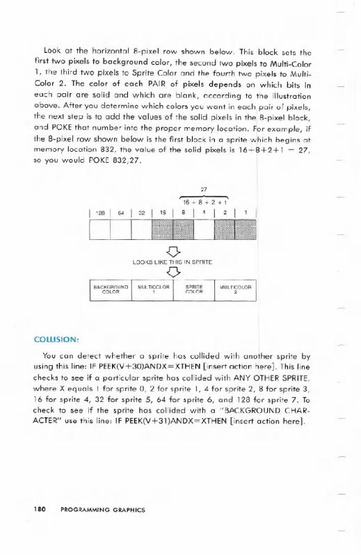
Look at the horizontal 8-pixel row shown below. This block sets thefirst two pixels to background color, the second two pixels to Multi-Color1, the third two pixels to Sprite Color and the fourth two pixels to Multi-Color 2. The color of each PAIR of pixels depends on which bits ineach pair are solid and which are blank, according to the illustrationabove. After you determine which colors you want in each pair of pixels,the next step is to add the values of the solid pixels in the 8-pixel block,and POKEthat number into the proper memory location. For example, ifthe 8-pixel row shown below is the first block in a sprite which begins atmemory location 832, the value of the solid pixels is 16+8+2+1 = 27,so you would POKE 832,27.
27
, 16 + 8 + 2 + l'
I 8 I 4 I 2 I 1 I
COLLISION:
You can detect whether a sprite has collided with another sprite byusing this line: IF PEEK(V+30)ANDX=XTHEN [insert action here]. This linechecks to see if a particular sprite has collided with ANY OTHERSPRITE,where X equals 1 for sprite 0, 2 for sprite 1, 4 for sprite 2, 8 for sprite 3,16 for sprite 4, 32 for sprite 5, 64 for sprite 6, and 128 for sprite 7. Tocheck to see if the sprite has collided with a "BACKGROUND CHAR-ACTER" use this line: IF PEEK(V+3l)ANDX=XTHEN [insert action here].
180 PROGRAMMING GRAPHICS
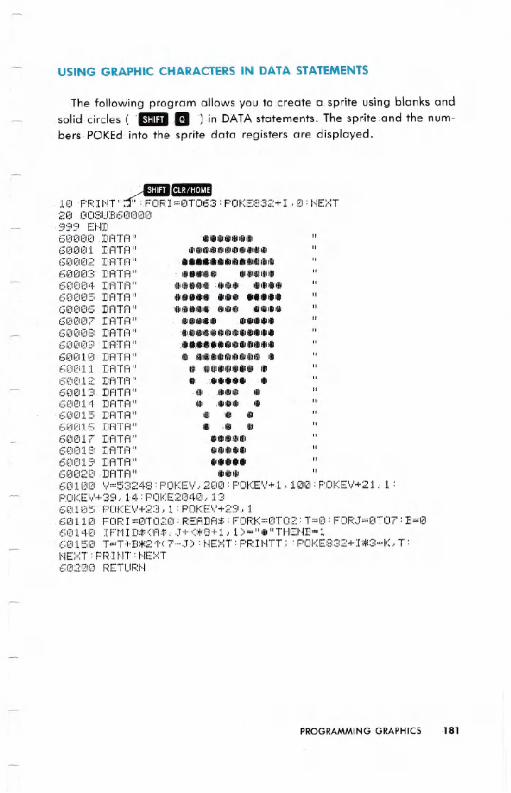
USING GRAPHIC CHARACTERS IN DATA STATEMENTS
The following program allows you to .create Q.sprite using blanks andsolid circles ( ').in DATAstatements. The spr~te:and the num-bers. POKEd .into the sprite data registers are displayed.
.:-BllilCIIiIII18 PR!NT" ~ :FiJRI =8T063 : POKE832+ I .' 8 : HE)<:T:;-~8GOSU:E:6iZ1000
.999 Et.m6IZU,;I0€1DATA".......613001 IIATA" GI1IiI..dill "61,miZ12DATA" ,Ii.6130103 DATA" 811I1111I'11I1106012ltNDATI=t" .'IIII.iP8 ....613£11215DATA" .... .....6013iZI6DATA" '1lilDiP....6121131217DATA" .....60808 DATA"...Ci.............6(18£19 DA'TA "..............6€11211121IIATA" . ...111..'11I"111'.'Ii612112111DATA" 11II...111... .68tH2 DATA" " .60813DATA"GI 1Ii1ill.613014DATA" . ,... ..60015 DATA" 011I. .68016 DATA" II .. ..613817DATA" .....601318DfiTI"i" .....68819 DATA" .....61302121.DATA" ...601£1(1 '11=53248: POKEV, 21313:POKEV+1.. 10121:POKEV+21, 1 :POKEV+39,14:POKE2848,136~U 1215F.'OKE'y'+23, 1 : POKEV+29, 16121110 FOR I =(1T020 :.READA$ : FORK=0T02 : T=13: FOF:J=1<n07 : B=13612114121IFtlID$(,A$.. J+K:+:8+1.. 1 )="."THEHB=l6015121 T=T+B*2'f'(7-~T): HEXT: PRIHTT.; : POKE832+I*:;:HK, T:NE:>::T : PFH t-n : t'IE>':T
612121210 RETUR:t.1
PROGRAMMING GRAPHICS .181