common document technical specification … · odisha power transmission corporation limited common...
TRANSCRIPT
ODISHA POWER TRANSMISSION CORPORATION LIMITED
COMMON DOCUMENT
TECHNICAL SPECIFICATION
VOLUME-II (PART-I)

CONTENTS OF THE TECHNICAL BIDDING DOCUMENTS (VOL-II)
CHAPTER No DESCRIPTION PAGES
E1 GENERAL CLAUSES 1-13
E2 GENERAL TECHNICAL CLAUSES FOR DESIGN 1-34
E3 SYSTEM DATA 1-2
E4 GENERAL METEROLOGICAL DATA 1-2
E5 DESIGN CLAUSES FOR SUB STATION 1-8
E6 CIVIL WORKS '1-84
E7 SWITCHYARD STRUCTURE 1-9
E8 DRAWING,TEST CERTIFICATE,O&M MANUALS 1-16
E9 ELECTRICAL EQUIPMENT INSTALLATION &
COMMISSIONING
1-12
E10 GENERAL EQUIPMENT & SUBSTATION
ACCESSORIES
1-25
E11 CIRCUIT BREAKER 1-55
E12 CURRENT TRANSFORMER 1-37
E13 ISOLATORS 1-16
E14 STATION TRANSFORMER 1-18
E15 SURGE ARRESTER 1-21
E16 IVT,CVT 1-29
E17 BATTERY & BATTERY CHARGER 1-30
E18 PLCC 1-35
E19 DISTRIBUTION BOARD 1-25
E20 CONDUCTOR,EARTH
WIRE,INSULATORS,HARDWARES, CLAMPS &
CONNECTORS
1-78
E21 CONTROL & PROTECTION PANEL,SAS & OUT
DOOR AC KIOSK
'1-98
E22 AIR CONDITIONER 1-3
E23 CONTROL &POWER & COAXIAL CABLES 1-30
E24 SUB STATION LIGHTING 1-10
E25 TESTING INSTRUMENTS &MAINTENANCE KITS 1-10
E26 TRANSMISSION LINES 1-91
E27 OPGW CABLE & ITS SYSTEM '1-39
E28 INDICATIVE DRAWING
E29 FIRE FIGHTING SYSTEM
E30 E30-GIS SS EQUIPMENT SPEC 220_33 KV GIS '1-42
E31 33 & 132 KV XLPE UG CABLE
E32 DIGITAL POWER LINE CAREER EQUIPMENT, TELEPROTECTION COUPLER & REMOTE TERMINAL UNIT (RTU)

E33 DISC / PORCELAIN LONG ROD INSULATORS FOR SUBSTATION AND TRANSMISSION LINE WORKS
E34 FOR HDG STEEL MONOPOLE
E35 FIBER OPTIC TERMINAL EQUIPMENT
VOL-II (TS) - -General-E1 Page 1/14
ODISHA POWER TRANSMISSION CORPORATION LIMITED
COMMON DOCUMENT
TECHNICAL SPECIFICATION
VOLUME-II (PART-I)
VOL-II (TS) - -General-E1 Page 2/14
GENERAL GENERAL CLAUSES
TABLE OF CONTENTS
1.4 Limit of contract ........................................................................................................................................... 4
2.GENERAL PARTICULARS OF SYSTEM ................................................................. 5
System description .............................................................................................................................................. 5
Substation description: ...................................................................................................................................... 5
Layout arrangement .......................................................................................................................................... 5
Meteorological data ............................................................................................................................................ 5
Soil data ............................................................................................................................................................... 6
Completeness and accuracy of information ..................................................................................................... 6
3.DRAWINGS ATTACHED WITH TENDER DOCUMENT........................................... 6
4.GUARANTEES TECHNICAL PARTICULARS ......................................................... 6
5.COMPLIANCE WITH SPECIFICATION .................................................................... 6
6.TEST AND MAINTENANCE EQUIPMENT ............................................................... 7
7.SPARES ................................................................................................................... 7
7.1 General .......................................................................................................................................................... 7
7.2 Mandatory spares......................................................................................................................................... 7
7.3 Optional spares ( shall not be considered for evaluation purpose). ......................................................... 7
8.0 TRAINING ............................................................................................................ 8
8.1 Hardware maintenance ................................................................................................................................ 8
8.2 Operator familiarisation .............................................................................................................................. 8
8.3 Software management .................................................................................................................................. 8
II.A) Installation and commissioning techniques ............................................................................................. 9
II.B) Proposals for training and manning ........................................................................................................ 9

VOL-II (TS) - -General-E1 Page 3/14
9.0 ERECTION AT SITE AND ACCOMMODATION ................................................. 10
10.0 SITE CONSTRUCTION SUPPLIES .................................................................. 10
11.0 SUPERVISION AND CHECKING OF WORK ON SITE ................................... 10
12.0 RESPONSIBILITY FOR THE RUNNING OF PLANT BY CONTRACTOR ....... 11
13.0 COMPLIANCE WITH REGULATIONS ............................................................. 11
14.0 MAINTENANCE AND CLEARING OF SITE ...................................................... 12
15.0 INSURANCE ...................................................................................................... 12
15.1 General ....................................................................................................................................................... 12
15.2 Workmen's Compensation Insurance ...................................................................................................... 12
15.3 Comprehensive auto mobile insurance .................................................................................................... 12
15.4 Comprehensive General Liability Insurance .......................................................................................... 13
16.0 PROTECTION OF MONUMENTS AND REFERENCE POINTS ...................... 13
17.0 WORK AND SAFETY REGULATIONS ............................................................ 13
18.0 FOREIGN PERSONNEL ................................................................................... 15

VOL-II (TS) - -General-E1 Page 4/14
1. GENERAL CONDITIONS
1.1 Responsibility of the Contractor
The Contractor shall also be responsible for the complete design and engineering, overall co-ordination
with internal and external agencies, project management, training of Employer’s manpower, loading,
unloading, storage at site, inventory management at site during construction, dismantling, re-erection of
installations as per Engg Incharge advice, handling, moving to final destination, obtaining statutory
authority’s clearance for successful erection, and testing and commissioning of the substation.
1.2 Specific exclusions:
The following items of work are specifically excluded from the Contractors scope of work unless
otherwise specifically brought out..
I. Substation site selection
II. Land acquisition
1.3 Interfacial point for line termination at substation
The line Contractor shall terminate the transmission line along with insulator hardware and other
essential fittings at the substation gantry. The substation Contractor shall provide necessary anchoring
plates in co-ordination with the transmission line contractor. The substation Contractor shall be
responsible for providing the necessary electrical interconnection from the line conductor to the
substation.
1.4 Limit of contract
The scope of work shall also include all work incidental for successful operation and commissioning
and handing over of works whether specifically mentioned or not. In general works are to be carried
out by the Contractor in accordance with stipulations in Conditions of Contract.
1.5 Quantity variation
The Employer reserves the right to order and delete such works which may be necessary for him within
the quantity variation option laid down in the conditions of the contract. This shall include but not be
limited to: the manufacture, supply, testing, and delivery to site, erection and commissioning as may be
required in accordance with the Conditions of Contract at the prices stated in the Schedules.
The Employer shall be at liberty to order from the Contractor such quantities of the apparatus at any
time before the expiration of the maintenance period of the scope of work, provided that such
quantities do not exceed the limitation of the Contract Value as defined in the Conditions of Contract.
Each separate order for Work at the Option of the Employer shall constitute a section for the purpose
of payment and taking over.
The Employer shall also be at liberty to delete from the Contractor such quantities of the apparatus at
any time before commencement of supply of works under the detailed scope of work.
1.6 Supply of non specified equipment/service during execution of contract.
The Employer may require the Contractor to supply and install a number of items such as testing and
measuring instruments, vehicles, repairing of existing equipment, removal and refurbishment of
plant/equipment from one place to another etc., which in the opinion of the Engg Incharge are to the
interest of the project execution. These items and services shall not be limited to proprietory goods
provided for the project.
Such supplies and services shall be reimbursed against supply and service invoices for
the materials or services actually supplied from the manufacturer or supplier of these items. The bidder
shall quote on cost for these items for the earmarked funds in appropriate schedules which shall be
considered in bid prices. How ever these costs shall be payable to the Contractor on pro rata basis for
the actual amount spent for procurement and availing of the services.

VOL-II (TS) - -General-E1 Page 5/14
For such items of supply the Contractor shall follow the fair principle of contracting
procedure to the satisfaction of Engg Incharge.
2. GENERAL PARTICULARS OF SYSTEM
System description
The following are the general particulars governing the design and working of the complete system of
which the Contract Works will eventually form a part:
Electrical energy is generated at a number of thermal and hydro power plants generally located in the
North, Central and Southern areas of Orissa State. The system is three phase, 50Hz and power is
transmitted at 400kV, 220kV and 132kV to the distribution system, via grid substations, which operate
at 33kV, 11kV and 400V. The 400kV and 220kV networks tie into the OPTCL's 400kV and 220kV
grid systems operated by OPTCL. The proposed works will increase the interconnection of, and will
thus reinforce the 400kV and 220kV networks within Orissa State. The detailed technical parameters
of the system are given in the schedules.
Substation description:
OPTCL has adopted the philosophy of installing open terminal air insulated substations. The busbars
for 400 KV rigid type and for 220 KV flexible strain type depending upon the choice of the designer
considering the overall suitability and economy of the substation to be installed.
Layout arrangement
The Contractor shall study the details of layout arrangements already indicated in the schedules details
for the existing substations. The bay width and height of the conductors for these substations shall be
achieved by the Contractor in case of extension substations. However the Contractor shall finalise the
layout arrangements in case of new substations in line with this Specification with the approval of the
Engg Incharge ,which shall be meeting at least the basic minimum electrical clearances as specified in
the schedules.
Location and site description
Details of the sub-substation locations, their approach , geography and topography has been provided
to the extent possible. The Bidder shall make necessary visit to the substation sites and fully appraise
himself before bidding. Deviations on account of inadequate data for substation works shall not be
acceptable and the Bid shall not be considered for evaluation in such cases.
Meteorological data
Appropriate meteorological data is given in the schedules.
Soil data
Detailed soil investigations in respect of various substations have not been made. However the general
characteristics of the soil are given in the schedules. The Contractor shall investigate the properties of
the substations and measure the soil resistivity as part of the scope of work.
Completeness and accuracy of information
The Contractor shall note that the information provided above and in the relevant schedules may not be
complete or fully accurate at the time of bidding. For his own interest the Contractor is advised to make
site visits and fully satisfy himself regarding site conditions in all respects, and shall be fully
responsible for the complete design and engineering of the substations.

VOL-II (TS) - -General-E1 Page 6/14
3. DRAWINGS ATTACHED WITH TENDER DOCUMENT
The various drawings and schedules provided are a part of the specification and for information
purposes only. These are not necessarily binding on the part of the Contractor. Bids shall be prepared
by the Bidder based on information provided in the drawings and schedules and that gathered by the
Bidder himself.
4. GUARANTEES TECHNICAL PARTICULARS
The Contract Works shall comply with the guaranteed technical particulars specified or quoted in the
bid. All plant and apparatus supplied under this Contract shall be to the approval of the Engg Incharge .
All plant and equipment supplied under this contract must have been type tested, have been in
manufacture and satisfactory service at identical ratings for at least two years. The bidder shall furnish
in his bid the necessary supporting data in specified formats for consideration during bid evaluation. If
during evaluation non compliance is identified the successful Contractor shall be bound to supply the
equipment from manufacturers complying with the stipulated requirements / OPTCL approval renders.
The Contractor shall be responsible for any discrepancies, errors or omissions in the particulars and
guarantees.
The Bidder for his own interest, shall establish the technical responsiveness of his bid, shall provide all
data in appropriate technical data sheets, general/ technical information, literature, and pamphlets etc.
along with the bid.
5. COMPLIANCE WITH SPECIFICATION
All apparatus should comply with this Specification. Any departures from the requirements of this
Specification shall be stated in the relevant Bid Proposal Schedules and will be considered during Bid
evaluation. Unless brought out clearly in the technical schedules, it will be presumed that the
equipment is deemed to comply with the technical specification.
In the event of there being any inconsistency between the provisions of the conditions of contract and
the provisions of this Specification in respect of commercial requirements, the provisions of the
conditions of contract shall take precedence for commercial matters and the provisions of this
Specification shall take precedence in respect of technical matters.
In case of inconsistency between technical specification & bid proposal sheet, quantities of various
items as specified in the bid proposal sheet shall be considered for quoting however the work shall be
executed as specified in the technical specification. Only brief description is given in the BPS & the
work shall be executed in line with the requirement given in the TS.
The manufacturer and places of manufacture, testing and inspection of the various portions of the
Contract Works shall be stated in the relevant Bid Proposal Schedules.
6. TEST AND MAINTENANCE EQUIPMENT
The Contractor shall supply the type and quantity of test and maintenance equipment specified in the
Schedules as part of the contract works.
7. SPARES
7.1 General
The Contractor shall provide the mandatory spares detailed in the Schedules. Provide a list of
recommended spare parts (optional spares) together with their individual prices, but that will not be
considered for evaluation. The Employer may order all or any of the Optional spare parts listed at the
time of contract award . Mandatory spares shall be supplied as part of the Works under this
VOL-II (TS) - -General-E1 Page 7/14
specification. Additional spares(Mandatory) may be ordered at any time during the contract at the rates
stated in the Price Schedule.
7.2 Mandatory spares
The Employer has indicated the requirement of mandatory spares as a percentage of the population of
main equipment together with proposed storage locations. The quantities shall be determined by the
Contractor and indicated in the relevant Bid Price Schedules. These quantities shall be considered for
evaluation of the bids.
7.3 Optional spares ( shall not be considered for evaluation purpose).
The Contractor may recommend a list of optional spare parts together with the quantity and usage rates
for their equipment in the relevant Bid Proposal Schedule. The Engg Incharge shall assess their
requirement and place orders.
The spares shall include consumable items sufficient for a plant operational period of five years after
commissioning, as well as essential replacement parts to cover the event of a break-down which would
affect the availability or safety of the plant. Spares shall be available during the life of the equipment
and the Contractor shall give 12 months notice of his, or any sub-contractor’s, intention to cease
manufacture of any component used in the equipment.
The Contractor shall ensure that sufficient spare parts and consumable items are available for his own
use during commissioning of the plant. Spares ordered by the Employer shall not be used by the
Contractor without the written consent of the Engg Incharge and any spares so used by the Contractor
during the commissioning of the plant shall be replaced by the Contractor at the Contractor’s expense.
Any spare apparatus, parts and tools shall be subject to the same specification, tests and conditions as
similar material supplied under the Scope of Works of the Contract. They shall be strictly
interchangeable and suitable for use in place of the corresponding parts supplied with the plant and
must be suitably marked and numbered for identification and prepared for storage by greasing or
painting to prevent deterioration.
All spare apparatus or materials containing electrical insulation shall be packed and delivered in cases
suitable for storing such parts or material over a period of years without deterioration. Such cases shall
have affixed to both the underside and topside of the lid a list detailing its contents. The case will
remain the property of the Employer.
8 .0 TRAINING
The Contractor will be required to provide suitable training for selected staff both on site and at the
Contractor's place of work. Details of the training considered appropriate shall be stated clearly, at the
bidding stage, based on the number of trainees specified. The cost of training including all course fees
shall be included.
The areas in which it is considered training should be provided, and duration of the training courses,
are given in this section. Alternative arrangements, where considered appropriate, should be suggested.
Four categories of training are considered appropriate namely :
I. Hardware maintenance.
II. Operator familiarisation.
III. Software management.
IV. Installation and commissioning techniques.

VOL-II (TS) - -General-E1 Page 8/14
8.1 Hardware maintenance
Courses for hardware maintenance shall identify techniques for preventative physical maintenance and
for identification, isolation and replacement of faulty components. This course shall take place before
equipment is delivered to site.
An essential part of the hardware maintenance course shall include highlighting the philosophy of
computer based preventive maintenance and identification of the various diagnostic/interrogation
facilities available. The Contractor shall supply adequate documented instructions to enable a detailed
interrogation and analysis process to be carried out using the diagnostic software facilities. All items of
hardware to be supplied shall be covered by the course.
8.2 Operator familiarisation
This course is intended to familiarise the operators with the system and its use in operating and
controlling the PLCC network. The course shall ensure that the control room staff are completely
familiar with all operational aspects of the equipment. The means of obtaining special data, report logs
and all other facilities which would enable the operators to be fully conversant with the system, shall
also be incorporated.
It is envisaged that it will be necessary for the Contractor to run operator familiarisation courses each
of approximately one week in duration at site for the training of the Employer's staff.
8.3 Software management
This course shall comprise two main areas and shall take place at the Contractor's works before
equipment is delivered to site .
I). A FORMAL COURSE ON THE SOFTWARE FOR EPAX ETC. DETAILING THE
VARIOUS MODULES USED AND THEIR INTERACTION.
II). A PRACTICAL COURSE ON EDITING THE DATABASE (TO INCORPORATE
EXTENSIONS TO THE POWER NETWORKS, INCLUSION OF ADDITIONAL
ANALOGUE/DIGITAL SIGNALS FROM EXISTING EQUIPMENT, ETC.) AND
GENERATING NEW LOGS, ALPHANUMERIC DISPLAYS, ETC.
It is envisaged that the software management courses shall extend for a period of approximately six
weeks.
II.A) Installation and commissioning techniques
The Employer's staff will be present during the installation and commissioning period and it is
essential that they be fully involved in any on-site corrections or modifications to hardware and
software equipment.
It is envisaged that it will be necessary for the Contractor to run installation and commissioning
techniques courses each of approximately one week in duration at site for the training of the
Employer's staff.
II.B) Proposals for training and manning
For each course recommended the following information shall be provided:
I. Course name and identification.
II. Short description of the curriculum.
III. Level of competency required for each course.
IV. Date and duration.
V. Maximum number of staff that can attend.
VI. Location.
VOL-II (TS) - -General-E1 Page 9/14
VII. Other important information.
The times at which the various training courses will take place shall be stated, and fully documented
notes shall be available to the Employer not later than two months before the commencement of the
course.
All training course notes and documentation shall be in the English language.
An estimate of the total number of the Employer's staff required to run, operate and service the works
covered by this Specification shall be given if this is different to the numbers specified.
The prices of the training courses shall be detailed in full such that additions or deletions to personnel
or courses can be calculated by the Employer without necessarily having to contact the Contractor.
This is particularly important for the 'Software management' courses where prices for formal course
days and practical course days shall be individually detailed.
9 .0 ERECTION AT SITE AND ACCOMMODATION
The Contractor shall provide, at his own cost and expense, all labour, plant and material necessary for
unloading and erection at the Site and shall be entirely responsible for its efficient and correct
operation.
The Contractor shall be responsible for arranging and providing all living accommodation services and
amenities required by his employees. He shall also provide suitable office accommodation at each
substation site for the sole use by the Engg Incharge (Divisional Engr.) for new substations only.
10 .0 SITE CONSTRUCTION SUPPLIES
The Contractor shall provide at his own cost and expense, any site supplies of electrical energy which
he may require for supplying power for heavy erection plant, welding plant or other tools and lighting
and testing purposes.
All wiring for such tackle and for lighting from the point of supply shall be provided by the Contractor
and all such installations shall comply with all appropriate statutory regulations to which the Employer
is subject.
Wiring shall be of the best quality double insulated flexible cable, suitably fixed, protected and
maintained. All necessary precautions shall be taken to ensure the safety of every person employed or
working on the Site and this shall include routine inspection of all temporary installations and portable
equipment.
The Engg Incharge or his authorised representative may require the disconnection or alteration of any
parts which he may consider dangerous.
As soon as any part or the whole of the Contractor’s installation is no longer required for the carrying
out of the works, the Contractor shall disconnect and remove the same to the satisfaction of the Engg
Incharge or his authorised representative.
The contractor shall be responsible for arranging construction water at his own cost.
How ever in case water is available at any substation site, Contractor may request Engg Incharge for
availing water at one point, which shall be charged to the contractor at prevailing rates for supply of
water by Govt. Dept. / Municipal Authorities.
In no case the work shall suffer on account of the Employer not making available the supply of water
and electricity for construction purposes.
11.0 SUPERVISION AND CHECKING OF WORK ON SITE
All work on site included in the Contract scope of works shall be supervised by a sufficient number of
qualified representatives of the Contractor.
VOL-II (TS) - -General-E1 Page 10/14
Before putting any plant or apparatus into operation the Contractor shall satisfy himself as to the
correctness of all connections between the plant and apparatus supplied under this and other contracts.
The Contractor shall advise the Engg Incharge in writing, giving the period of notice as specified in the
General Conditions of Contract, when the plant or apparatus is ready for inspection or energisation.
12 .0 RESPONSIBILITY FOR THE RUNNING OF PLANT BY CONTRACTOR
Until each Section of the Contract Works has been taken over or deemed to have been taken over under
the Conditions of Contract, the Contractor shall be entirely responsible for the Contract Works,
whether under construction, during tests, or in use for the Employer’s service.
The Contractor shall instruct the Employer’s operating staff in the recommended method of
operation of the plant supplied. Such instruction shall commence prior to the commissioning of the
plant and shall be followed by practical instruction for a period of up to one month after the plant is
taken over by the Employer. During this one month period the Contractor shall provide an engineer, on
each site that is taken over, to assist with operation of the plant and to provide on-site training of the
Employer’s operating staff. The training schedule and programme for each substation shall be
submitted to the Engg Incharge for approval, three months prior to the substation’s planned completion
date.
If the Employer shall so require, the Contractor shall provide the services of a skilled engineer
acquainted with the running of the plant for any period required by the Employer between commencing
of use of any portion of the plant (whether taken over or not) and the expiry of the period of
maintenance, the wages for such services being paid by the Employer to the Contractor, except in
respect of the carrying out of any work already covered by the Contractor’s obligations under this
Contract.
When the Contractor ceases to be obliged to maintain a supervising engineer on the Site under the
foregoing provisions of this clause, the Contractor shall, until the expiration of the period of
maintenance, make such arrangements as to ensure the attendance on site within 24 hours of being
called upon by the Engg Incharge of a competent supervising engineer for the purpose of carrying out
any work of maintenance or repair for which the Contractor shall be liable. During such part or parts of
the said period as the Engg Incharge shall deem it necessary the said representative shall be
continuously available on the Site.
Any work which may be necessary for the Contractor to carry out in pursuance of his obligations under
the Conditions of Contract shall be carried out with the minimum of interference to the normal
operation of the substation. Work on the Site shall be carried out at such time and during such hours as
the Engg Incharge may require.
13 .0 COMPLIANCE WITH REGULATIONS
All apparatus and material supplied, and all work carried out shall comply in all respects with such of
the requirements of all Regulations and Acts in force in the country of the Employer as are applicable
to the Contract Works and with any other applicable regulations to which the Employer is subject.
The Contractor shall fully inform himself of the requirements of the local Laws, Regulations and rules
in-force in the State of Orissa, especially with respect to local employment laws, licensing
requirements, electrical safety rules and regulations, building regulations and planning procedures.
The Contractor shall be responsible for applying for all necessary licenses; including Electrical
Contractors License, Workman’s Permits and Certificates of Competency for Supervisors, and local
government approvals required for the contract works and for the payment of all necessary fees
associated with such licenses and approvals.
Correspondence with the Electrical Inspector shall be conducted through the Engg Incharge (Divisional
Engr.), but the Contractor shall provide all necessary information, regarding the contract works, as may
be required by the Electrical Inspector.

VOL-II (TS) - -General-E1 Page 11/14
Additionally the Contractor shall also follow the minimum regulations on safety, employees welfare,
industry etc. as stipulated under the relevant Clause of this section.
14 .0 MAINTENANCE AND CLEARING OF SITE
The placing of materials and plant near the erection site prior to their being erected and installed shall
be done in a neat, tidy and safe manner. The Contractor shall at his own expense keep the site area
allocated to him and also the erection area of the Contract Works reasonably clean and shall remove all
waste material as it accumulates and as directed by the Engg Incharge from time to time.
15 .0 INSURANCE
15.1 General
In addition to the conditions covered under the Clause titled insurance in the Special Conditions of
Contract, the following provisions will also apply to the portion of works to be done beyond the
Suppliers own or his sub-Contractors manufacturing Works.
15.2 Workmen's Compensation Insurance
This insurance shall protect the Contractor against all claims applicable under the Workmen’s
Compensation Act, 1948 (Government of India). This policy shall also cover the Contractor against the
claims for injury, disability, disease or death of his or his sub-contractor's employees, which for any
reason are not covered under the Workman’s Compensation Act, 1948. The liabilities shall not be less
than;
I. Workmen’s’ Compensation As per statutory provisions
II. Employee's liability As per statutory provisions
* According to the Govt. rules.
15.3 Comprehensive auto mobile insurance
This insurance shall be in a such a form to protect the Contractor against all claims for injuries,
disability, disease and death to members of public including the Employer's men and damage to the
property of others arising from the use of motor vehicles during on or off the Site operations,
irrespective of the ownership of such vehicles. The minimum liability covered shall be as herein
indicated:
I. Fatal Injury : Rs. 100,000/- each person
II. Property : Rs. 200,000/- each occurrence
III. Damage : Rs. 100,000/- each occurrence
* As per latest prevailing Govt. rules.
15.4 Comprehensive General Liability Insurance
This insurance shall protect the Contractor against all claims arising from injuries, disabilities, disease
or death of members or public or damage to property of others, due to any act or omission on the part
of the Contractor, its agents, its employees, its representatives and sub-contractors or from riots, strikes
and civil commotion.
The hazards to be covered will pertain to all works and areas where the Contractor, its sub-contractors,
agents and employees have to perform work pursuant to the Contracts.
The above are only an illustrative list of insurance covers normally required and it will be the
responsibility of the Contractor to maintain all necessary insurance coverage to the extent both in time
and amount to take care of all its liabilities either direct or indirect, in pursuance of the Contract.

VOL-II (TS) - -General-E1 Page 12/14
16.0 PROTECTION OF MONUMENTS AND REFERENCE POINTS
The Contractor shall ensure that any finds such as relics, antiques, coins, fossils, etc. which he may
come across during the course of performance of his works either during excavation or elsewhere, are
properly protected and handed over to the Employer. Similarly, the Contractor shall ensure that the
bench marks, reference points, etc. which are marked either with the help of Employer or by the
Employer shall not be disturbed in any way during the performance of his works. If any work is to be
performed which disturbs such reference points, the same shall be done only after these are transferred
to other suitable locations under the direction of the Employer. The Contractor shall provide all
necessary materials and assistance for such relocation of reference points etc.
17 .0 WORK AND SAFETY REGULATIONS
The Contractor shall ensure safety of all the workmen, plant and equipment belonging to him or to
others, working at the Site. The Contractor shall also provide for all safety notices and safety
equipment required by the relevant legislation and deemed necessary by the Engg Incharge .
The Contractor will notify, well in advance to the Engg Incharge, his intention to bring to the
Site any container filled with liquid or gaseous fuel, explosive or petroleum substance or such
chemicals which may involve hazards. The Engg Incharge shall have the right to prescribe the
conditions under which such a container is to be stored, handled and used during the performance of
the works and the Contractor shall strictly adhere to and comply with such instructions. The Engg
Incharge shall also have the right, at his sole discretion, to inspect any such container or such
construction plant and equipment for which materials in the container is required to be used and if in
his opinion, its use are not safe, he may forbid their use.
No claim due to such prohibition or towards additional safety provisions called for by him
shall be entertained by the Employer.
Further, any such decision of the Engg Incharge shall not, in any way, absolve the Contractor of his
responsibilities and in case use of such a container or entry thereof into the Site areas is forbidden by
the Engg Incharge the Contractor shall use alternative methods with the approval of the Engg Incharge
without any cost implication to the Employer or extension of work schedule.
Where it is necessary to provide and/or store petroleum products or petroleum mixtures and
explosives, the Contractor shall be responsible for carrying out such provision and/or storage in
accordance with the rules and regulations laid down in Petroleum Act 1934, Explosives Act 1948 and
amendments thereof, and Petroleum and Carbide of Calcium Manual published by the Chief Inspector
of Explosives of India. All such storage shall have prior approval of the Engg Incharge. In case, any
approval is necessary from the Chief Inspector (Explosives) or any statutory authorities, the Contractor
shall be responsible for obtaining the same.
All equipment used in construction and erection by Contractor shall meet Indian or
International Standards and where such standards do not exist, the Contractor shall ensure these to be
absolutely safe. All equipment shall be strictly operated and maintained by the Contractor in
accordance with manufacturers operation manual and safety instructions and as per any existing
Guidelines/Rules in this regard.
Periodical examinations and all tests for all lifting and hoisting equipment and tackle shall be carried
out in accordance with the relevant provisions of Factories Act 1948, Indian Electricity (Supply) Act
and associated Laws/Rules in force, from time to time. A register of such examinations and tests shall
be properly maintained by the Contractor and will be promptly produced as and when desired by Engg
Incharge.
The Contractor shall provide suitable safety equipment of prescribed standard to all employees and
workmen according to the need, as may be directed by the Engg Incharge who will also have the right
to examine such safety equipment to determine it’s suitability, reliability, acceptability and
adaptability.

VOL-II (TS) - -General-E1 Page 13/14
Where explosives are to be used, the same shall be used under the direct control and supervision of an
expert, experienced and qualified competent person, strictly in accordance with the Code of
Practices/Rules framed under Indian Explosives Act pertaining to handling, storage and use of
explosive.
Contractors employing more than 250 workmen whether temporary, casual, probationer, regular or
permanent or on contract, shall employ at least one full time officer exclusively as Safety Officer to
supervise safety aspects of the equipment and workmen. Such an officer will co-ordinate with the
Project Safety officer of the Employer.
The name and address of the Safety Officer of the Contractor will be promptly informed in writing to
the Engg Incharge with a copy to the Safety Officer-in-charge before he starts work or immediately
after any change of the incumbent is made during currency of the Contract.
In case any accident occurs during the construction, erection or other associated activities undertaken
by the Contractor, thereby causing any minor or major or fatal injury to his employees due to any
reason whatsoever, it shall be the responsibility of the Contractor to promptly inform the same to the
Engg Incharge and also to all the authorities envisaged under the applicable laws.
The Engg Incharge shall have the right at his sole discretion to stop the work, if in his opinion the work
is being carried out in such a way as may cause accidents or endanger the safety of the persons and/or
equipment. In such cases, the Contractor shall be informed in writing about the nature of hazards and
possible injury/accident and he shall remove shortcomings immediately. The Contractor, after stopping
the specific work, can if felt necessary appeal against the order of stoppage of work to the Engg
Incharge within three days of such stoppage of work and the decision of the Engg Incharge in this
respect shall be conclusive.
The Contractor shall not be entitled for any damages or compensation for stoppage of work due to
safety reasons and the period of such stoppage of work will not be taken as an extension of time for
completion of work, nor will it be the grounds for waiver of any part of suppliers liability for timely
completion of the works.
The Contractor shall follow and comply with all Safety Rules, relevant provisions of applicable laws
pertaining to the safety of workmen, employees, plant and equipment as may be prescribed from time
to time without any demur, protest or contest or reservation. In case of any conflict between statutory
requirement and Safety Rules referred above, the most stringent clause shall be applicable.
If the Contractor fails in providing safe working environment as per Safety Rules or continues the
works even after being instructed to stop work by the Engg Incharge, the Contractor shall promptly pay
to the Employer on demand, compensation at the rate of Rs. 5,000/- per day or part thereof till the
instructions are complied with and so certified by the Employer. However, in case of accident taking
place causing injury to any individual, the provision contained in subsequent paragraph as here below
shall also apply in addition to the compensation mentioned in this paragraph.
If the Contractor does not take all safety precautions and comply with Safety Rules as prescribed by the
Engg Incharge or as prescribed under the applicable law, to safeguard equipment, plant and personnel
the Contractor shall be responsible for payment of compensation to the Employer as per the schedule
given below.
If the Contractor does not prevent hazardous conditions which may cause injury to his own employees,
employees of other Contractors, or the Employer or any other person at Site or adjacent thereto, the
Contractor shall be responsible for payment of compensation to the Employer as per the following
Schedule:
Fatal injury or accident causing death.
Rs. 100,000/- per
person
Applicable for injury or death to
any person whomsoever.
Major injuries or accident causing 25% or
more permanent disability.
Rs. 20,000/- per
person
Applicable for injury or death to
any person whomsoever.

VOL-II (TS) - -General-E1 Page 14/14
* As per prevailing Govt. rules.
Permanent disability shall have the same meaning as indicated in Workmen's Compensation Act. The
compensation mentioned above shall be in addition to the compensation payable to the
workmen/employees under the relevant provisions of the Workmen's Compensation Act and rules
framed thereunder or any other applicable law as applicable from time to time. In case the Employer is
made to pay such compensation, the Contractor will reimburse the Employer such amount(s) in
addition to the compensation indicated above.
18 .0 FOREIGN PERSONNEL
If necessary for the execution of the works, the Contractor shall bring foreign supervisors for the
execution of the Contract at his own cost. The Contractor shall submit to the Employer data on all
personnel he proposes to bring into India for the performance of the works under the Contract, at least
Sixty (60) days prior to their arrival in India. Such data shall include the name of each person, his
present address, his assignment and responsibility in connection with the works, and a short resume of
his qualifications and experience etc. in relation to the work to be performed by him.
Any person unsuitable and unacceptable to the Employer, shall not be brought to India. Any person
brought to India, and found unsuitable or unacceptable to the Employer shall be immediately removed
from Site and repatriated. If found necessary, he may be replaced by other personnel acceptable to the
Employer.
No person brought to India by the Contractor for the works shall be repatriated without the consent of
the Employer in writing, based on a written request from the Supplier for such repatriation giving
reasons for such an action to the Employer. The Employer may give permission for such repatriation
provided the Employer is satisfied that the progress of work will not suffer due to such repatriation.
The cost of passports, visas and all other travel expenses to and from India, shall be to the Contractor's
account. The Employer will not provide any residential accommodation and/or furniture for any of the
Contractors personnel including foreign personnel. Contractor shall make his own arrangements for
such facilities.
The Contractor and his expatriate personnel shall respect all Indian Acts, Laws, Rules and Regulations
and shall not in any way, interfere with Indian political and religious affairs and shall conform to any
other rules and regulations which the Government of India, and the Employer may establish on them.
The Contractor’s expatriate personnel shall work and live in close co-operation and co-ordination with
their co-workers and the community and shall not engage themselves in any other employment either
part-time or full-time nor shall they take part in any local politics.
The Employer shall assist the Contractor, to the extent possible, in obtaining necessary certificates and
other information needed by the Government agencies.

VOL-II (TS) E2-GENERAL TECHNICAL CLAUSE- Page 1 of 39
ODISHA POWER TRANSMISSION CORPORATION LIMITED
COMMON DOCUMENT
OFFICE OF THE SR. GENERAL MANAGER,
CENTRAL PROCUREMENT CELL,
JANAPATH, BHUBANESWAR – 751022.
TECHNICAL SPECIFICATION
FOR
GENERAL TECHNICAL CLAUSES
FOR DESIGN
GENERAL TECHNICAL CLAUSES
TABLE OF CONTENTS

VOL-II (TS) E2-GENERAL TECHNICAL CLAUSE- Page 2 of 39
............................................................................................................................. 1
ORISSA POWER TRANSMISSION CORPORATION LIMITED ................................. 1
1. GENERAL ................................................................................................................. 6
2. DESIGN AND STANDARDISATION ........................................................................ 6
3. 0 QUALITY ASSURANCE ........................................................................................ 7
3.1. General ......................................................................................................................................................... 7
3.2. Quality assurance programme ................................................................................................................... 7
3.3. Quality plans ................................................................................................................................................ 8
3.4. Inspection and testing ................................................................................................................................. 8
3.5. Non-conforming product ............................................................................................................................ 9
3.6. Monitoring of quality arrangements ......................................................................................................... 9
3.7. Sub-contractors ........................................................................................................................................... 9
3.8. Method statement ........................................................................................................................................ 9
4. 0 HEALTH, SAFETY AND ENVIRONMENT (HSE) PLAN ....................................... 9
4.1. General ......................................................................................................................................................... 9
4.2. Content of HSE Plan ................................................................................................................................... 9
4.3. General structure of HSE Plan ................................................................................................................ 10
4.4. Section 6 of HSE Plan ............................................................................................................................... 11
4.5. Standards, Procedures and Guidelines .................................................................................................... 11
4.6. Supervision strategy .................................................................................................................................. 11
5. 0 PROGRESS REPORTING ................................................................................... 11
6. 0 STANDARDS ....................................................................................................... 12
7. 0 LANGUAGE AND SYSTEM OF UNITS ............................................................... 13
8. 0 CORRESPONDENCE, DRAWINGS, APPROVAL PROCEDURE AND SAMPLES ................................................................................................................... 13
8.1. Correspondence ......................................................................................................................................... 13

VOL-II (TS) E2-GENERAL TECHNICAL CLAUSE- Page 3 of 39
8.2. Drawings and samples .............................................................................................................................. 13
8.3. Approval procedure .................................................................................................................................. 14
8.4. Final as-built drawings ............................................................................................................................. 15
8.5. Operation and Maintenance Manuals ..................................................................................................... 16
9. 0 MASS AND SIZE OF PARTS AND QUANTITIES OF OIL .................................. 16
10. 0 GENERAL REQUIREMENTS ............................................................................ 16
10.1. Bolts and nuts .......................................................................................................................................... 16
10.2. Galvanising. ............................................................................................................................................. 17
10.2.1. General .............................................................................................................................. 17
10.2.2. Galvanising ....................................................................................................................... 17
10.3. Cleaning, painting and tropicalisation ................................................................................................. 18
10.3.1. General .............................................................................................................................. 18
10.3.2. Works painting processes ................................................................................................. 18
10.3.3. Site painting ...................................................................................................................... 19
10.4. Provision for exposure to hot and humid climate ................................................................................. 21
10.4.1. Anti-condensation Provisions: .......................................................................................... 21
10.4.2. Fungistatic treatment ........................................................................................................ 21
10.4.3. Ventilating specifications ................................................................................................. 21
10.5. Labels and plates ..................................................................................................................................... 21
10.6. Padlocks ................................................................................................................................................... 22
10.7. Earthing .................................................................................................................................................. 23
10.8. Lubrication .............................................................................................................................................. 23
11. PRODUCTION PROCESS REQUIREMENTS ...................................................... 23
11.1. Castings .................................................................................................................................................... 23
11.1.1. General .............................................................................................................................. 23
11.1.2. Iron castings ...................................................................................................................... 23
11.1.3. Steel castings .................................................................................................................... 24
11.2. Forgings .................................................................................................................................................... 24
11.3. Fabricated components ........................................................................................................................... 24
11.4. Welding and welders qualifications ....................................................................................................... 24
11.4.1. General .............................................................................................................................. 24

VOL-II (TS) E2-GENERAL TECHNICAL CLAUSE- Page 4 of 39
11.4.2. Welding ............................................................................................................................ 25
11.4.3. Welding of pipes ............................................................................................................... 26
12. WIRING, CABLING AND CABLE INSTALLATION ............................................ 27
12.1. Cubicle wiring .......................................................................................................................................... 27
12.2. LV power cabling .................................................................................................................................... 29
12.3. Multi-core cables and conduit wiring .................................................................................................... 29
12.4. Laying and installing of cables ............................................................................................................... 30
12.4.1. General .............................................................................................................................. 30
12.4.2. Laying of cable ................................................................................................................. 30
12.4.3. Cable tags and markers ..................................................................................................... 31
12.4.4. Cable supports and cable tray mounting arrangements in control room........................... 31
12.4.5. Cable support structure in switchyard cable trenches ....................................................... 31
12.5. Termination of cables and wires ............................................................................................................ 32
13. 0 DEGREES OF PROTECTION ........................................................................... 32
14. 0 SUPPLY VOLTAGE ........................................................................................... 32
15. 0 MAINTENANCE TELEPHONE POSITIONS ..................................................... 33
16. 0 ERECTION CONDITIONS ................................................................................. 33
16.1. General ..................................................................................................................................................... 33
16.2. Regulation of local authorities and statutes .......................................................................................... 33
16.3. Inspection, testing and inspection certificates ....................................................................................... 33
16.4. Contractor's field operation ................................................................................................................... 34
16.4.1. General .............................................................................................................................. 34
16.4.2. Progress Report ................................................................................................................. 34
16.5. Facilities to be provided by the contractor ............................................................................................ 34
16.5.1. Unloading ......................................................................................................................... 34
16.5.2. Tools, tackle and scaffoldings .......................................................................................... 34
16.6. First-Aid and general hygiene ................................................................................................................ 34
16.7. Security..................................................................................................................................................... 35
16.8. Materials handling and storage .............................................................................................................. 35
17. 0 CONSTRUCTION MANAGEMENT ................................................................... 35
VOL-II (TS) E2-GENERAL TECHNICAL CLAUSE- Page 5 of 39
17.1. General ..................................................................................................................................................... 35
17.2. Field office records .................................................................................................................................. 35
17.3. Protection of property and Contractor's liability ................................................................................. 36
18. 0 CODE REQUIREMENTS ................................................................................... 36
19. 0 EMPLOYER'S SUPERVISION .......................................................................... 36
20. 0 TESTING AND INSPECTION ............................................................................ 36
21. 0 FIRE PRECAUTIONS ........................................................................................ 37
22. 0 PACKING, SHIPPING AND TRANSPORT ........................................................ 38
23. 0 ERECTION MARKS ........................................................................................... 39
24. 0 SPANNERS AND SPECIAL TOOLS ................................................................. 39
25. 0 RUNWAY BEAMS, EYE BOLTS AND LIFTING TACKLE ................................ 39
1. GENERAL
The following provisions shall supplement all the detailed technical specifications and requirements
brought out in accompanying Technical Specifications. The Contractor‟s proposal shall be based upon
the use of equipment and materials complying fully with the requirements specified herein. It is
recognised that the Contractor may have standardised on the use of certain components, materials,
processes or procedures different to those specified herein. Alternate proposals offering similar
equipment based on the manufacturers standard practice will also be considered, provided such
proposals meet the specified design standard and performance requirement and are acceptable to the
Engg. Incharge.
2. DESIGN AND STANDARDISATION
The Works covered by the specification shall be designed, manufactured, built, tested and
commissioned in accordance with the Act, Rules, Laws and Regulations of India. The Equipment(s)
shall also conform to the requirements detailed in the referred standards, which shall form an integral
part of the Specification, in addition to meeting the specific requirements called for elsewhere in the
Specification.
The Contract works shall be designed to facilitate inspection, cleaning and repairs, and for operation
where continuity of supply is the first consideration. Apparatus shall be designed to ensure satisfactory
operation in all atmospheric conditions prevailing at the Site(s) and during such sudden variation of
load and voltage as may be met with under working conditions on the system, including those due to
faulty synchronising and short circuit.
The design shall incorporate all reasonable precautions and provisions for the safety of those concerned
in the operation and maintenance of the Contract Works and of associated works supplied under other
contracts.
Where the Specification does not contain characteristics with reference to workmanship, equipment,
materials and components of the covered equipment, it is understood that the same must be new, of

VOL-II (TS) E2-GENERAL TECHNICAL CLAUSE- Page 6 of 39
highest grade of the best quality of their kind, conforming to best engineering practice and suitable for
the purpose for which they are intended.
In case where the equipment, materials or components are indicated in the specification as 'similar' to
any special standard, the Engg. Incharge shall decide upon the question of similarity. When required by
the Specification; or when required by Engg. Incharge the Contractor shall submit, for approval, all the
information concerning materials or components to be used in manufacture. Machinery, equipment,
materials and components supplied, installed or used without such approval shall run the risk of
subsequent rejection, it being understood that the cost as well as the time delay associated with the
rejection shall be borne by the Contractor.
The design of the Works shall be such that installation, future expansions, replacements and general
maintenance may be undertaken with a minimum of time and expense. Each component shall be
designed to be consistent with its duty and suitable factors of safety, subject to mutual agreements and
shall be used throughout the design. All joints and fastenings shall be so devised, constructed and
documented that the component parts shall be accurately positioned and restrained to fulfil their
required function.
All outdoor apparatus and fittings shall be designed so that water cannot collect at any point.
Grease lubricators shall be fitted with nipples and where necessary for accessibility, the nipples shall be
placed at the end of extension piping.
All water and oil pipe flanges shall be to IS 6392/BS 4504 or other equivalent standard, as regards both
dimensions and drilling, unless otherwise approved.
Cast iron shall not be used for chambers of oil filled apparatus or for any part of the equipment which is
in tension or subject to impact stresses.
Kiosks, cubicles and similar enclosed compartments shall be adequately ventilated to restrict
condensation. All contractor or relay coils and other parts shall be suitably protected against corrosion.
All apparatus shall be designed to obviate the risk of accidental short circuit due to animals, birds,
insects, mites, rodents or micro-organisms.
Corresponding parts shall be interchangeable. Where required by the Engg. Incharge the Contractor
shall demonstrate this quality.
3. 0 QUALITY ASSURANCE
3.1. General
To ensure that the supply and services under the scope of this Contract, whether manufactured or
performed within the Contractor‟s works or at his Sub-Contractor‟s premises or at Site or at any other
place of work are in accordance with the Specification, with the Regulations and with relevant Indian
or otherwise Authorised Standards the Contractor shall adopt suitable Quality Assurance Programmes
and Procedures to ensure that all activities are being controlled as necessary.
The quality assurance arrangements shall conform to the relevant requirements of ISO 9001 or ISO
9002 as appropriate.
The systems and procedures which the Contractor will use to ensure that the Works comply with the
Contract requirements shall be defined in the Contractor‟s Quality Plan for the Works.
The Contractor shall operate systems which implement the following:
Hold Point “A stage in the material procurement or workmanship process beyond which work shall
not proceed without the documented approval of designated individuals or organisations.”
The Engg. Incharge written approval is required to authorise work to progress beyond the Hold Points
indicated in approved Quality Plans.

VOL-II (TS) E2-GENERAL TECHNICAL CLAUSE- Page 7 of 39
Notification Point “A stage in material procurement or workmanship process for which advance
notice of the activity is required to facilitate witness.”
If the Engg. Incharge does not attend after receiving documented notification in accordance with the
agreed procedures and with the correct period of notice then work may proceed.
3.2. Quality assurance programme
Unless the Contractor‟s Quality Assurance System has been audited and approved by the Engg.
Incharge, a Quality Assurance Program for the Works shall be submitted to the Engg. Incharge for
approval a minimum of one month prior to commencement of the works, or such other period as shall
be agreed with the Engg. Incharge. The Quality Assurance Program shall give a description of the
Quality System for the Works and shall, unless advised otherwise, include details of the following:
The structure of the Contractor‟s organisation
The duties and responsibilities assigned to staff ensuring quality of work
The system for purchasing, taking delivery and verification of materials
The system for ensuring quality of workmanship
The system for the control of documentation
The system for the retention of records
The arrangements for the Contractor‟s internal auditing
A list of the administration and work procedures required to achieve and verify the Contract‟s
Quality requirements. These procedures shall be made readily available to the Engg. Incharge for
inspection on request.
3.3. Quality plans
The Contractor shall draw up for each section of the work Quality Plans which shall be submitted to
the Engg. Incharge for approval at least two weeks prior to commencement of the particular section.
Each Quality Plan shall set out the activities in a logical sequence and, unless advised otherwise, shall
include the following:
An outline of the proposed work and program sequence
The structure of the Contractor‟s organisation for the Contract
The duties and responsibilities assigned to staff ensuring quality of work for Contract
Hold and Notification points
Submission of engineering documents required by the Specification
The inspection of materials and components on receipt
Reference to the Contractor‟s work procedures appropriate to each activity
Inspection during fabrication/construction
Final inspection and test
3.4. Inspection and testing
The prime responsibility for inspection and testing rests with the Contractor. The inspection or its
waiver by the Engg. Incharge does not relieve the Contractor of any obligations or responsibilities to
carry out the work in accordance with the Contract.
VOL-II (TS) E2-GENERAL TECHNICAL CLAUSE- Page 8 of 39
The inspection and testing shall be documented such that it is possible to verify that it was performed.
Records of inspection shall include as a minimum the contract identity, operation/inspection, technique
used, acceptance standard, acceptability, identity of inspector/tester and date of inspection/test.
3.5. Non-conforming product
The Contractor shall retain responsibility for the disposition of non-conforming items.
3.6. Monitoring of quality arrangements
During the course of the Contract the Engg. Incharge may monitor the implementation of the Quality
Assurance arrangements. Monitoring will be by surveillance of the activities at work locations and/or
by formal audits of the adherence of the Contractor to the systems and procedures which constitute his
Quality Assurance arrangements. Corrective actions shall be agreed and implemented in respect of any
deficiencies
The Contractor shall provide any facilities, including access, which may be required by the Engg.
Incharge for monitoring activities.
The Engg. Incharge may participate on an agreed basis in the Contractor‟s monitoring of a sub-
contractor‟s Quality Assurance arrangements.
3.7. Sub-contractors
The Contractor shall ensure that the Quality Assurance requirements of this Specification are followed
by any sub-contractor appointed by him under the Contract.
The Contractor shall assess the sub-contractor‟s Quality Assurance arrangements prior to his
appointment to ensure its compliance with the appropriate ISO 9000 standard and the Specification.
Auditing of the sub-contractor‟s Quality Assurance arrangements shall be carried out by the Contractor
and recorded in such a manner that demonstrates to the Engg. Incharge the extent of the audits and
their effectiveness.
3.8. Method statement
Prior to commencing work, the Contractor shall submit a method statement setting out full details of
his method of working. This is a Hold Point.
Details of the Contractor‟s method of working shall also be submitted at the time of Bidding.
4. 0 HEALTH, SAFETY AND ENVIRONMENT (HSE) PLAN
4.1. General
Within one month of award of contract the Contractor shall produce a HSE Plan for the contract and
submit for the approval of the Engg. Incharge . The HSE Plan is described in the following sections.
The primary objective of the HSE Plan is for the contractor to demonstrate that he has the capability to
carry out the contract work in a cost effective manner, giving due consideration to the Health, Safety
and Environmental management of both his own employees, those of the Employer and anyone who
may be affected by his activities.
4.2. Content of HSE Plan
The general structure of the HSE Plan is outlined in 1.9.8.3. The HSE Plan will comprise two parts i.e.:
Part : I : Sections 1 to 5, covering general HSE management and controls.
The following would be attached as appendices, where appropriate:
Organisation chart showing the proposed Contractors HSE organisational structure

VOL-II (TS) E2-GENERAL TECHNICAL CLAUSE- Page 9 of 39
The CV‟s, duties and responsibilities of the following personnel:
(i) Contract Manager
(ii) Contractors Site Representatives
(iii) Safety Officer
(iv) Site Safety Officers
Part : II : Section 6, providing a summary of hazards and controls.
4.3. General structure of HSE Plan
The HSE Plan shall conform to the following general structure:
1. Contractors Policy Statement
2. Health
2.1 First Aid
2.2 Primary health care
2.3 Occupational health
3. Safety
3.1 Objectives and targets
3.2 Organisation and responsibilities
3.3 HSE meetings
3.4 Motivation and communication
3.5 HSE training
3.6 Audits and inspections
3.7 Emergency response
3.8 Safety function
3.9 Accident investigating and reporting
3.10 Standards
3.11 Personal protective equipment
4. Environment
4.1 Waste management
4.2 Chemicals management
4.3 Environmental impact
5. Critical areas
5.1 Subcontractors
6. Summary of hazards and controls
4.4. Section 6 of HSE Plan
In addition to general hazards and their controls, the following hazards have been identified as specific
to this contract and therefore the contractor should demonstrate that he is capable of providing the
necessary controls for the work:
Working within a Permit to Work system

VOL-II (TS) E2-GENERAL TECHNICAL CLAUSE- Page 10 of 39
Working adjacent to live high voltage equipment
Working adjacent to, and in the vicinity of, live high voltage overhead lines
Working at elevation
Lifting operations
Use of explosives
Use of heavy machinery including cranage, pile rigs and concrete mixers
Excavation works
Work in confined spaces
Working with insulating oil
Working with compressed gas
Rotating machinery
The Contractor should demonstrate his understanding of these hazards by either proposing specific
controls for each of them or by giving supporting documentation which demonstrates that such controls
already exist.
4.5. Standards, Procedures and Guidelines
The HSE Plan shall identify the Standards, Procedures and Guidelines that will be applicable to the
project. These will include the Indian Electricity Rules and The OPTCL Operations Safety Manual -
1997 (Draft), and will be subject to the approval of the Engg. Incharge (Divisional Engr.).
4.6. Supervision strategy
The Contractor will provide supervisors with a minimum of five years experience of this type of work
such that they are able to supervise the quality and standards of the work without intervention by the
Employer. The role of the Employer will be to monitor and audit the quality of the work to ensure that
it is of adequate standard and that it is being safely and successfully managed.
5. 0 PROGRESS REPORTING
The Contractor shall submit for approval, within four weeks of the issue of letter of award, an outline
of the design, engineering, material procurement, production, site mobilisation, man and machine
deployment, delivery, erection, testing, commissioning, and handing over programme. Within a further
period of 4 weeks the Contractor shall provide a detailed programme of all these activities in a form to
be agreed by the Engg. Incharge . The Contractor shall submit monthly progress reports to the Engg.
Incharge office not later than the fifth day of the following month. The reports shall show clearly and
accurately the position of all activities associated with design, material procurement, manufacture,
works tests, shipping, site erection, testing and commissioning with regard to the agreed contract
programme.
In addition to the routine monthly progress report the Contractor shall also submit to the Engg.
Incharge by the 25th day of every month, a man hour schedule for the following month, detailing the
man hours scheduled for that month, skill-wise and area-wise.
The preferred format for presentation of programmes is MS Project version 4.0 or any latest. The
programmes and monthly updates shall be submitted on CD.
The design aspect of the progress report shall include a comprehensive statement on drawing and
calculations submitted for approval.

VOL-II (TS) E2-GENERAL TECHNICAL CLAUSE- Page 11 of 39
The position on material procurement shall give the date and details of orders placed and indicate the
delivery date quoted by the manufacturer. If any delivery date has an adverse affect on the contract
programme the Contractor shall state the remedial action taken to ensure that delays do not occur.
The position on manufacture shall indicate the arrival of material, the progress of manufacture and date
at which the equipment will be ready for transport. Any events that may adversely affect completion in
the manufacturers works shall also be reported.
All works tests executed shall be listed and the test-results shall be remarked upon. Any test failures
shall be highlighted and the Contractor shall detail the necessary steps taken in order to avoid any
adverse affect on the contract completion dates.
The despatch of each order shall be monitored on the progress report giving the date by which the
equipment will be available for transport, the estimated time of arrival on site and the dates actually
achieved.
The site works shall be segregated into civil, mechanical and electrical works for reporting purposes
and each section of the site works shall be monitored giving the percentage completion and the
estimated completion date in accordance with the contract programme. The number of men working on
site, both labour and supervisory staff, shall be reported together with any incidents or events that may
affect the progress of site works.
Any delays which may affect any milestone or final completion dates shall be detailed by the
Contractor who shall state the action taken to effect contract completion in accordance with the
contract programme.
The contractor shall provide two copies of the progress report to the Engg. Incharge (Divisional Engr.)
office.
6. 0 STANDARDS
Except where otherwise specified or implied, the Contract Works shall comply with the latest edition
of the relevant Indian Standards, International Electrotechnical Commission (IEC) standards and any
other standards mentioned in this Specification. The Contractor may submit for approval, equipment or
materials conforming to technically equivalent National Standards. In such cases copies of the relevant
Standards or part thereof, in the English language shall be submitted with the Tender. In case of
conflict the order of precedence shall be (1) IEC, (2) IS and (3) other alternative standard.
Reference to a particular standard or recommendation in this Specification does not relieve the
Contractor of the necessity of providing the Contract Works complying with other relevant standards or
recommendations.
The list of standards provided in the schedules of this Specification is not to be considered exhaustive
and the Contractor shall ensure that equipment supplied under this contract meets the requirements of
the relevant standard whether or not it is mentioned therein.
7. 0 LANGUAGE AND SYSTEM OF UNITS
The English language shall be used in all written communications between the Employer, the Engg.
Incharge (Divisional Engr.) and the Contractor with respect to the services to be rendered and with
respect to all documents and drawings procured or prepared by the Contractor pertaining to the work,
unless otherwise agreed by the Employer.
It is required that danger plates, equipment designation labels or plates, instruction notices on plant and
general substation notices be written in English, Hindi and Oriya. Control switch and lamp labels,
indicator lamp and annunciator inscriptions shall be in English only.
The Contractor must furnish a schedule giving the English, Hindi and Oriya version of all labels,
notices, etc., for approval.
The design features of all equipment shall be based on the SI system of units.

VOL-II (TS) E2-GENERAL TECHNICAL CLAUSE- Page 12 of 39
8. 0 CORRESPONDENCE, DRAWINGS, APPROVAL PROCEDURE AND SAMPLES
8.1. Correspondence
All correspondence shall be addressed to the Sr. G.M, TP, OPTCL / Sr. G.M, C.P.C, OPTCL
8.2. Drawings and samples
A list of the drawings to be submitted by the Contractor with his Bid and a list of drawings and samples
to be submitted after the Commencement Date, are to be given in the Schedules. The Contractor shall
also provide free of charge any additional drawings and/or copies of any drawing required by the Engg.
Incharge. All design drawings and calculations shall be submitted for approval not later than 180 days
after commencement of the contract.
Within 30 days of contract commencement the Contractor shall submit, for approval by the Engg.
Incharge a schedule of the drawings to be produced detailing which are to be submitted for
“Approval” and which are to be submitted “For Information Only”. The schedule shall also provide a
programme of drawing submission, for approval by the Engg. Incharge that ensures that all drawings
and calculations are submitted within the period specified above.
Details of the loads and fixing arrangements of the circuit breakers and transformers, supplied under a
separate contract, shall be provided by the Engg. Incharge in order to enable the Contractor to design
the foundations for these items of plant.
All drawings submitted by the Contractor including those submitted at the time of bid shall be in
sufficient detail to indicate the type, size, arrangement, material description, Bill of Materials, weight
of each component, break-up for packing and shipment, the external connections, fixing arrangement,
and the dimensions, required for installation and interconnections with other equipment and materials,
clearances and spaces required for installation and interconnections between various portions of
equipment and any other information specifically requested in the specification.
The Contractor shall submit samples of materials for approval as required from time to time by the
Engg. Incharge .
All dimensions marked on drawings shall be considered correct although measurement by scale may
differ from general arrangement drawings. Detailed drawings shall be worked to where they differ
from general arrangement drawings.
All detail drawings submitted for approval shall be to scale not less than 1 : 20. All important
dimensions shall be given and the material of which each part is to be constructed shall be indicated on
the drawings.
All documents, drawings and samples shall be submitted in accordance with the provisions of this
Specification and shall become the property of the Employer.
All drawings and calculations, submitted to the Engg. Incharge shall be on international standard size
paper, either A0, A1, A2, A3 or A4. All such drawings and calculations shall be provided with a
contract title block and shall be assigned a unique project drawing number; the contact title block and
project numbering system shall be agreed with the Engg. Incharge .
All drawings for approval shall have the OPTCL-LOGO and the name of the Employer.
Technical drawings must be shown, in such a form that the information necessary to construct an
installation or part of an installation must be understandable by the technicians/skilled workmen
responsible for construction and supervision. The drawings must therefore conform to following
standards.
For presentation of design drawings and circuit documents IEC Publication 617 or equivalent standards
for graphical symbols are to be followed.
Script sizes and thickness of scripts and lines be selected so that if reduced by two stages the
alphanumeric characters and lines are still perfectly legible so as to microfilm them .
VOL-II (TS) E2-GENERAL TECHNICAL CLAUSE- Page 13 of 39
8.3. Approval procedure
The Contractor shall submit all drawings and samples for approval in sufficient time to permit
modifications to be made if such are deemed necessary, and the drawings and samples to be re-
submitted without delaying the initial deliveries or completion of the Contract Works. The following
schedule shall be adhered for submission, approval, re-submission and final distribution drawings/
documents.
Initial submission: All drawings, designs and documents requiring
approval of Engg. Incharge - not later than 100
days from award of contract.
Approval/comments of 1st
submission:
Within 30 days of receipt.
Re-submission where required: Within 21 days of receipt including postal time
both ways.
Approval/comments of re-
submission:
Within 15 days of receipt.
Submission of distribution copies: Within 15 days of approval.
Three copies of all drawings shall be submitted for approval and three copies for any
subsequent revision. The Engg. Incharge reserves the right to request any additional information that
may be considered necessary in order to fully review the drawings. Drawings for approval shall be
submitted as paper prints and shall bear the approved contract references. Submittal should where
possible be staggered to facilitate maintenance of the above schedule.
If the Engg. Incharge is satisfied with the drawing, one copy will be returned to the Contractor marked
with “Approved” stamp. If the Engg. Incharge is not totally satisfied with the drawing, then “Approved
subject to comment” status will be given to it and a comment sheet will be sent to the Contractor. If the
drawing does not comply with the requirements of the specification then it will be given “Not
Approved” status and a comment sheet will be sent to the Contractor. In both the latter cases the
Contractor will have to modify the drawing, update the revision column and resubmit for final
approval.
Following approval copies of final drawings will be required as given below.
Reproducible on Tracing Films or Papers : 3 copies
Hard Copies on paper (Blue print or Xerox) : 20 copies
Computer CD ROM : 1 copy
Any drawing or document submitted for information only should be indicated as such by the
Contractor. Drawings submitted for information only will not be returned to the Contractor unless the
Engg. Incharge considers that such drawings do need to be approved, in which case they will be
returned suitably stamped with comments.
Drawings, samples and models submitted by the Contractor and approved by the Engg. Incharge shall
not be departed from without the instruction in writing of the Engg. Incharge .
The Contractor shall be responsible for any discrepancies or errors in or omissions from the drawings,
whether such drawings have been approved or not by the Engg. Incharge . Approval given by the Engg.
Incharge (Divisional Engr.)to any drawing or sample shall neither relieve the Contractor from his
liability to complete the Contract Works in accordance with this Specification and the conditions of
contract nor exonerate him from any of his guarantees.
VOL-II (TS) E2-GENERAL TECHNICAL CLAUSE- Page 14 of 39
If the Contractor needs approval of any drawing within a period of less than four weeks in order to
avoid delay in the completion of the Contract Works, he shall advise the Engg. Incharge when
submitting the drawings and provide an explanation of the document‟s late submission. The Engg.
Incharge will endeavour to comply with the Contractors time scale, but this cannot be guaranteed.
8.4. Final as-built drawings
After completion of work on site all drawings shall be revised where necessary to show the equipment
as installed and three copies submitted duly signed by site-in-charge. Following approval, two
reproducible transparencies and twenty prints shall then be provided as required by the Engg. Incharge
and shall be of sufficient detail to enable all parts to be identified. The contractor shall also submit,
where possible, digitally stored copies of all as-built drawings on disc or CD-ROM in a format
compatible with the Employer‟s drawing system.
8.5. Operation and Maintenance Manuals
Six months prior to the contractual completion date for each substation site the Contractor shall
forward to the Engg. Incharge, two copies of the Operation and Maintenance Manual unique to the
substation site being handed over.
After approval by the Engg. Incharge the Contractor shall deliver ten (10) copies of the complete
manual .
The Taking Over Certificate will not be issued until the required number of approved copies of the
manuals have been provided by the Contractor.
The manuals shall be as complete and as specific as possible and shall incorporate documentation that
is specific to the materials and equipment used on the contract. Because the nature of the work varies
from site to site the manuals will have to be tailored to the specific needs of each site.
All precautions and warnings relative to the safety of life and equipment shall be included in the
manuals.
The manuals should also show exploded views wherever required.
9. 0 MASS AND SIZE OF PARTS AND QUANTITIES OF OIL
The mass and dimensions of any item of equipment shall not exceed the figures stated in the Schedules.
Each item shall be labelled to indicate its mass, quantity of oil (if any) and any special handling
instructions.
10. 0 GENERAL REQUIREMENTS
10.1. Bolts and nuts
All bolts, studs, screw threads, pipe threads, bolt heads and nuts shall comply with the appropriate
national standards for metric threads, or the technical equivalent.
Except for small wiring, current carrying terminal bolts or studs, for mechanical reasons, shall not be
less than 6 mm in diameter.
All nuts and pins shall be adequately locked.
Wherever possible bolts shall be fitted in such a manner that in the event of failure of locking resulting
in the nuts working loose and falling off, the bolt will remain in position.
All bolts, nuts and washers placed in outdoor positions shall be treated to prevent corrosion, by hot dip
galvanising or electro galvanising to service condition 4. Appropriate precautions shall be taken to
prevent electrolytic action between dissimilar metals.
VOL-II (TS) E2-GENERAL TECHNICAL CLAUSE- Page 15 of 39
Where bolts are used on external horizontal surfaces where water can collect, methods of preventing
the ingress of moisture to the threads shall be provided.
Each bolt or stud shall project at least one thread but not more than three threads through its nut, except
when otherwise approved for terminal board studs or relay stems. If bolts and nuts are placed so that
they are inaccessible by means of ordinary spanners, special spanners shall be provided.
The length of the screwed portion of the bolts shall be such that no screw thread may form part of a
shear plane between members.
Taper washers shall be provided where necessary.
Protective washers of suitable material shall be provided front and back on the securing screws.
10.2. Galvanising.
10.2.1. General
All machining, drilling, welding, engraving, scribing or other manufacturing activities which would
damage the final surface treatment shall be completed before the specified surface treatment is carried
out.
10.2.2. Galvanising
All metal surfaces shall be subjected to treatment for anti-corrosion protection. All ferrous surfaces for
external use shall be hot dip galvanised. High tensile steel nuts, bolts and spring washers shall be
electro galvanised to service condition 4. All steel conductors including those used for earthing and
grounding (above ground level) shall also be galvanised according to IS 2629.
All galvanising shall be applied by the hot dip process and shall comply with IS 2629, IS 2633, IS
4759, IS 1367 or IS 6745.
All welds shall be de-scaled, all machining carried out and all parts shall be adequately cleaned prior to
galvanising. The preparation for galvanising and the galvanising itself shall not adversely affect the
mechanical properties of the coated material.
The threads of all galvanised bolts and screwed rods shall be cleared of spelter by spinning or brushing.
A die shall not be used for cleaning the threads unless specially approved by the Engg. Incharge
(Divisional Engr.). All nuts shall be galvanised with the exception of the threads which shall be oiled.
Surfaces which are in contact with oil shall not be galvanised or cadmium plated.
Partial immersion of the work will not be permitted and the galvanising tank must therefore be
sufficiently large to permit galvanising to be carried out by one immersion.
Galvanising of wires shall be applied by the hot dip process and shall meet the requirements of
IS 2141.
The minimum weight of the zinc coating shall be 610 gm/sq.m and minimum thickness of coating shall
be 86 microns for all items thicker than 5 mm. For items of less than 5 mm thickness requirement of
coating thickness shall be as per BS 729. For surface which shall be embedded in concrete, the zinc
coating shall be a minimum of 800 gm/sq.m.
The galvanised surfaces shall consist of a continuous and uniform thick coating of zinc, firmly
adhering to the surface of steel. The finished surface shall be clean and smooth and shall be free from
defects such as discoloured patches, bare spots, unevenness of coating, spelter which is loosely
attached to the steel globules, spiky deposits, blistered surface, flaking or peeling off, etc. The presence
of any of these defects noticed on visual or microscopic inspection shall render the material liable to
rejection.
After galvanising no drilling or welding shall be performed on the galvanised parts of the equipment
excepting that nuts may be threaded after galvanising. Sodium dichromate treatment shall be provided
to avoid formation of white rust after hot dip galvanisation.

VOL-II (TS) E2-GENERAL TECHNICAL CLAUSE- Page 16 of 39
The galvanised steel shall be subjected to six one minute dips in copper sulphate solution as per IS
2633.
Sharp edges with radii less than 2.5 mm shall be able to withstand four immersions of the Standard
Preece test. All other coatings shall withstand six immersions. The following galvanising tests should
essentially be performed as per relevant Indian Standards.
Coating thickness
Uniformity of zinc
Adhesion test
Mass of zinc coating
Galvanised material must be transported properly to ensure that galvanised surfaces are not damaged
during transit. Application of zinc rich paint at site shall not be allowed.
10.3. Cleaning, painting and tropicalisation
10.3.1. General
All paints shall be applied in strict accordance with the paint manufacturer‟s instructions.
All painting shall be carried out on dry and clean surfaces and under suitable atmospheric and other
conditions in accordance with the paint manufacturer‟s recommendations.
An alternative method of coating equipment such as with epoxy resin-based coating powders will be
permitted, subject to the approval of the Engg. Incharge (Divisional Engr.), and such powders shall
comply with the requirements of IEC 455. The Contractor shall provide full details of the coating
process to the Engg. Incharge (Divisional Engr.)for approval.
It is the responsibility of the Contractor to ensure that the quality of paints used shall withstand the
tropical heat and extremes of weather conditions specified in the schedules. The paint shall not peel off,
wrinkle, be removed by wind, storm and handling on site and the surface finish shall neither rust nor
fade during the service life of the equipment.
The colours of paints for external and internal surfaces shall be in accordance with the approved colour
schemes .
10.3.2. Works painting processes
All steelworks, plant supporting steelworks and metalwork, except galvanised surfaces or where
otherwise specified, shall be shot blasted to BS 7079 or the equivalent ISO standard. All sheet steel
work shall be degreased, pickled, phosphated in accordance with the IS 6005 “Code of Practice for
phosphating iron and sheet steel”. All surfaces shall then be painted with one coat of epoxy zinc rich
primer, two pack type, to a film thickness of 50 microns. This primer shall be applied preferably by
airless spray and within twenty minutes but not exceeding one hour of shot blasting.
All rough surfaces of coatings shall be filled with an approved two pack filler and rubbed down to a
smooth surface.
The interior surfaces of all steel tanks and oil filled chambers shall be shot blasted in accordance with
BS 7079 or the equivalent ISO, and painted within a period of preferably twenty minutes, but not
exceeding one hour with an oil resisting coating of a type and make to the approval of the Engg.
Incharge (Divisional Engr.).
The interior surfaces of mechanism chambers, boxes and kiosks, after preparation, cleaning and
priming as required above, shall be painted with one coat zinc chromate primer, one coat phenolic
based undercoating, followed by one coat phenolic based finishing paint to a light or white colour. For
equipment for outdoor use this shall be followed by a final coat of anti-condensation paint of a type and
make to the approval of the Engg. Incharge (Divisional Engr.), to a light or white colour. A minimum
overall paint film thickness of 150 microns shall be maintained throughout.
VOL-II (TS) E2-GENERAL TECHNICAL CLAUSE- Page 17 of 39
All steelworks and metalwork, except where otherwise specified, after preparation and priming as
required above shall be painted with one coat metallic zinc primer and two coats of micaceous iron
oxide paint followed by two coats of either phenolic based or enamel hard gloss finished coloured paint
to the approval to an overall minimum paint film thickness of 150 microns.
Galvanised surfaces shall not be painted in the works.
All nuts, bolts, washers etc., which may be fitted after fabrication of the plant shall be painted as
described above after fabrication.
The painted metal works shall be subjected to paint qualification test as per draft ANSI/IEEE-Std 37.21
-1985 clause 5.2.5.
10.3.3. Site painting
After erection at site, the interior surfaces of mechanism chambers and kiosks shall be thoroughly
examined, and any deteriorated or mechanically damaged surfaces of such shall be made good to the
full Specification described above.
After installation/erection at site all surfaces of steelworks and metalwork shall be thoroughly washed
down. Any deteriorated or otherwise faulty paint-work removed down to bare metal and made good to
the full Specification described above, then painted one further coat of phenolic based undercoating
and one coat phenolic based hard gloss finishing paint to provide an overall minimum paint film
thickness of 200 microns.
Any nuts, bolts, washers, etc., which have been removed during site erection, or which may be required
to be removed for maintenance purposes shall be restored to their original condition.
All paint work shall be left clean and perfect on completion of the works.
10.3.4 Colour Schemes The Contractor shall propose a colour scheme for the sub-station for the
approval of Engg. Incharge (Divisional Engr.). The decision of Engg. Incharge (Divisional Engr.)shall
be final. The scheme shall include:
Finishing colour of indoor equipment
Finishing colour of outdoor equipment
Finish colour of all cubicles
Finishing colour of various auxiliary system equipment including piping.
Finishing colour of various building items.
All steel structures, plates etc. shall be painted with non-corrosive paint on a suitable primer. It may be
noted that normally all Employer‟s electrical equipment in Employer‟s switchyard are painted with
shade 631 of IS:5 and Employer will prefer to follow the same for this project also. All indoor cubicles
shall be of same colour scheme and for other miscellaneous items colour scheme will be subject to the
approval of the Engg. Incharge (Divisional Engr.).
Sl. No.
Equipment Application Environment
Indoor Outdoor
Colour Code
IS:5 Colour Code
IS:5
400kV/220kV/132kV Class Equipment 1 Transformers — — Light grey 631
2 Marshalling boxes, CTs, PT’s, CVT’s, surge counter casings, junction boxes etc.
Light Admiralty grey.
697 Light Admiralty grey.
697
3 Control and relay panels, PLCC cabinets etc. Smoke grey 692 — —
4 Porcelain parts i.e. insulators Dark brown 412 Dark brown 412
5 All structures/ metallic parts exposed to atmosphere
Hot dip galvanised

VOL-II (TS) E2-GENERAL TECHNICAL CLAUSE- Page 18 of 39
33kV Class equipment 6 Switchgear cubicles Smoke grey 692 Light grey 631
7 Control and relay panels Smoke grey 692 — —
LT switchgear
8 LT switchgear exterior Smoke grey 692 Light grey 631
9 ACDB/ MCC Smoke grey 692 Light grey 631
10 DCDB Smoke grey 692 — —
11 LT bus duct in side enclosure Matt Paint — —
12 LT bus duct outside enclosure Smoke grey 692 — —
13 Motors Smoke grey 692 Light grey 631
14 Diesel generator engine Smoke grey 692 — —
15 Diesel generator Smoke grey 692 — —
16 LT transformers Smoke grey 692 Light grey 631
17 Battery charger Smoke grey 692 — —
18 Mimic diagram 400kV 220kV
132kV 33kV 11kV
415V
Dark violet Golden yellow Sky blue Signal red Canary yellow Middle brown
796 356
101 537 309
411
— — — — — —
— —
— — —
—
Miscellaneous
19 Control modules and console inserts Smoke grey 692 Light grey 631
20 Lighting package equipment outside Light grey 631 Light grey 631
21 Lighting package equipment inside Glossy white Glossy white
22 Water pipes sea green 217 sea green 217
23 Air pipes Sky blue 101 Sky blue 101
24 Transformer oil pipes Light brown 410 Light brown 410
25 Fire Installations Fire red 536 Fire red 536
26 Insulating oil/ gas treatment plant Gulf red 473 Gulf red 473
Table 10.3.4. Recommended colour schemes
10.4. Provision for exposure to hot and humid climate
Outdoor equipment supplied under the Specification shall be suitable for service and storage under
tropical conditions of high temperature, high humidity, heavy rainfall and environment favourable to
the growth of fungi and mildew. The indoor equipments located in non air-conditioned areas shall also
be of same type.
10.4.1. Anti-condensation Provisions:
Space heaters where provided shall be suitable for continuous operation at 240V supply voltage. On-
off switch and fuse shall be provided.
One or more adequately rated permanently or thermostatically connected heaters shall be supplied to
prevent condensation in any compartment. The heaters shall be installed in the lower portion of the
compartment and electrical connections shall be made from below the heaters to minimise deterioration
of supply wire insulation. The heaters shall be suitable to maintain the compartment temperature at
approximately 10C, above the outside air temperature to prevent condensation. This shall be
demonstrated by tests.
10.4.2. Fungistatic treatment
Besides the space heaters, special moisture and fungus resistant varnish shall be applied to parts which
may be subjected or predisposed to the formation of fungi due to the presence or deposit of nutrient
substances. The varnish shall not be applied to any surface or part where the treatment will interfere
with the operation or performance of the equipment. Such surfaces or parts shall be protected against
the application of the varnish.

VOL-II (TS) E2-GENERAL TECHNICAL CLAUSE- Page 19 of 39
10.4.3. Ventilating specifications
In order to ensure adequate ventilation, compartments shall have ventilation openings provided with
fine wire mesh of brass or galvanised steel to prevent the entry of insects and to reduce to a minimum
the entry of dirt and dust. Outdoor compartment openings shall be provided with shutter type blinds.
10.5. Labels and plates
All apparatus shall be clearly labelled indicating, where necessary, its purpose and service positions.
Each phase of alternating current and each pole of direct current equipment and connections shall be
coloured in an approved manner to distinguish phase or polarity.
The material of all labels and the dimensions, legend, and method of printing shall be to approval. The
surface of indoor labels shall have a matt or satin finish to avoid dazzle from reflected light.
Colours shall be permanent and free from fading. Labels mounted on black surfaces shall have white
lettering. „Danger‟ plates shall have red lettering on a white background.
All labels and plates for outdoor use shall be of non corroding material. Where the use of enamelled
iron plates is approved, the whole surface including the back and edges, shall be properly covered and
resistant to corrosion. Protective washers of suitable material shall be provided front and back on the
securing screws.
Labels shall be engraved in Hindi, English and Oriya. Name plates shall be white with black engraved
lettering and shall carry all the applicable information specified in the applicable items of the
Standards.
Any other relevant information which may be required for groups of smaller items for which this is not
possible e.g. switch bays etc. a common name plate in Oriya with the title and special instructions on it
shall be provided.
No scratching, corrections or changes will be allowed on name plates.
All equipment mounted on front and rear sides as well as equipment mounted inside the panels shall be
provided with individual name plates with equipment designation engraved.
On the top of each panel on front as well as rear sides large name plates with bold size lettering shall be
provided for circuit/ feeder/ cubicle box designation.
All front mounted equipment shall be also provided, at the rear, with individual name plates engraved
with tag numbers corresponding to the one shown in the panel internal wiring to facilitate tracing of the
wiring. The name plates shall be mounted directly by the side of the respective equipment wiring.
Name plates of cubicles and panels may be made of non rusting metal or 3 ply lamicoid. These name
plates may be black with white engraved lettering.
The name plate inscription and size of name plates and letters shall be submitted to the Engg. Incharge
(Divisional Engr.)/Engineer for approval.
The nameplates of the apparatus shall include, at least, the information listed below, together with any
other relevant information specified in the applicable standards :
Concise descriptive title of the equipment
Rating and circuit diagrams
Manufacturer's name, trade-mark, model type, serial number
Instruction book number
Year of manufacture
Total weight (for capacitor racks indicate weight, for capacitors indicate quantity of liquid)
Special instructions, if any, about storage, transportation, handling etc.

VOL-II (TS) E2-GENERAL TECHNICAL CLAUSE- Page 20 of 39
Each measuring instrument and meter shall be prominently marked with the quantity measured e.g. kV,
A, MW etc. All relays and other devices shall be clearly marked with manufacturers name,
manufacturers type, serial number and electrical rating data.
Danger plates and plates for phase colours shall be provided as per requirement. The Contractor shall
devise a system to designate equipment and sub-systems. The nameplates/labels displaying these
designations shall be installed at appropriate locations. Whenever motion or flow of fluids is involved,
plates showing direction of motion or flow shall also be provided.
10.6. Padlocks
For each item of plant the Contractor shall provide a padlockable handle and a non-ferrous padlock
with different key changes in order to prevent access to control cabinets, cubicles and relay panels. The
Contractor shall provide two keys for each lock and a master key for each substation.
Cabinets for the accommodation of padlocks and keys, whilst not in use, shall be provided and shall be
suitably labelled so that keys will be readily identifiable.
10.7. Earthing
Metal parts of all equipment other than those forming part of an electrical circuit shall be connected
directly to the main earth system via two separate conductors of adequate capacity at two different
points.
All main members of structural steelworks shall be earthed by galvanised iron flat connections bonded
by welding or bolting to the steelworks.
Connections to apparatus and structures shall be made clear of ground level, preferably to a vertical
face and protected as appropriate against electrolytic corrosion. They shall be made between clean
surfaces and of sufficient size and pressure to carry the rated short circuit current without damage.
Earth bars installed directly into the ground should normally be laid bare and the trench back-filled
with a fine top soil. Where the soil is of a hostile nature, special precautions must be taken to protect
the earth bar, the method used being subject to the agreement of the Engg. Incharge (Divisional Engr.).
Joints in earth bars shall be welded and then coated with a suitable anti-corrosion protection treatment.
Facilities shall be provided on the earth bar run between equipment and the base of structures,
comprising a looped strip, so as to permit the attachment of portable earth connections for maintenance
purposes.
The cross sectional area of the earth bar and connections shall be such that the current density is not
greater than 100 A/mm2 for a 3 second fault duration.
10.8. Lubrication
Bearings which require lubrication either with oil or grease shall be fitted with nipples.
11. PRODUCTION PROCESS REQUIREMENTS
11.1. Castings
11.1.1. General
All castings shall be true to pattern, free from defects and of uniform quality and condition. The
surfaces of castings which do not undergo machining, shall be free from foundry irregularities. The
castings shall be subject to NDT, chemical, mechanical and metallographic tests. Details of the same
shall be furnished to Engg. Incharge (Divisional Engr.)for review/approval. Magnetic particle
inspection (MPI) test, wherever applicable, shall be carried out in longitudinal and transverse direction
to detect radial and axial cracks.

VOL-II (TS) E2-GENERAL TECHNICAL CLAUSE- Page 21 of 39
11.1.2. Iron castings
Iron casting material shall be in accordance with ASTM A 126 Class B. A copy of the ladle analysis
shall be sent to the Engg. Incharge (Divisional Engr.). Each casting shall have a test bar from which
tension test specimens may be taken. Test specimen shall be in accordance with ASTM A 370 and
tested in accordance with ASTM E8. The Contractor shall submit his procedures for testing and
acceptance for iron castings for approval by the Engg. Incharge (Divisional Engr.).
11.1.3. Steel castings
Steel castings shall be manufactured in accordance with ASTM A 27 and shall be subjected to
appropriate tests and inspection as detailed herein.
Copies of mandatory documentation, such as ladle analyses and mechanical test results, shall be sent to
the Engg. Incharge (Divisional Engr.). (Non-ferrous casting material and castings shall be
manufactured in accordance with the appropriate ASTM standards for the material concerned).
11.2. Forgings
When requested by the Engg. Incharge (Divisional Engr.), forgings will be subjected to inspection in
the regions of fillets and changes of section by suitable method. Magnetic particle, dye-penetration,
radiographic or ultrasonic, or any combination of these methods may be used to suit material type and
forging design.
The testing is to be carried out after the rough machining operation and is to be conducted according to
the appropriate ASTM standards.
MPI test on forging shall be carried out to detect both radial and axial cracks. Ferrous forgings shall be
demagnetised after such tests.
Any indentations which prove to penetrate deeper than 2.5% of the finished thickness of the forging
shall be reported to the Engg. Incharge (Divisional Engr.)giving location, length, width and depth. Any
indentations which will not machine out during final machining shall be gouged out and repaired using
an approved repair procedure.
Repair of rotating elements by welding will only be accepted subject to detailed examination of the
proposal by the Engg. Incharge (Divisional Engr.)prior to the repair being carried out.
The forging shall be tested for mechanical and metallographic tests as per ASTM. The details shall be
mutually discussed/agreed upon.
11.3. Fabricated components
All components machined or fabricated from plate, sheet or bar stock shall meet the material
requirements of ASTM or material specification approved by the Engg. Incharge (Divisional Engr.).
Structural steel, rolled shapes, bars, etc. shall comply with the latest ASTM for A36.
Plate steel shall be of a designation and quality suitable for the function it is intended to perform.
Insofar as it is compatible with its function, it shall comply with ASTM A283 structural quality.
All, or a representative number of such components, shall be subjected to one or more of the following
tests: visual, dye penetration, magnetic particle (transverse and longitudinal), ultrasonic or
radiographic. These tests shall be in accordance with the recommended practices of the ASTM. The
terms of reference for acceptance shall be the applicable ASTM Specifications.
11.4. Welding and welders qualifications
11.4.1. General
All welding shall be carried out by qualified welders only.
All welding shall be in accordance with the corresponding standards of the American Welding Society
or the American Society of Mechanical Engineers.

VOL-II (TS) E2-GENERAL TECHNICAL CLAUSE- Page 22 of 39
Other standards to determine the quality of welding process and qualifications of welders may be
considered, provided that sufficient information is first submitted for the approval of the Engg.
Incharge (Divisional Engr.).
Prior to the start of fabrication, the Contractor shall submit to the Engg. Incharge (Divisional Engr.)for
approval, a description of each of the welding procedures which he proposes to adopt, together with
certified copies of reports of the results from tests made in accordance with these procedures.
The Contractor shall be responsible for the quality of the work performed by his welding organisation.
All welding operators, to be assigned work, including repair of casting, shall pass the required tests for
qualification of welding procedures and operators. The Engg. Incharge (Divisional Engr.)reserves the
right to witness the qualification tests for welding procedures and operators and the mechanical tests at
the samples.
The Contractor shall bear all his own expenses in connection with the qualification tests. If the work of
any operator at any time appears questionable, such operator will be required to pass appropriate pre-
qualification tests as specified by the Inspector and at the expense of the Contractor.
11.4.2. Welding
All welding shall be performed in accordance with the appropriate standards. The design and
construction of welded joints subject to hydraulic pressure shall conform to the applicable requirement
of ASME “Boiler and Pressure Vessel Code” shall be qualified in accordance with Section IX of this
Code. The design and construction of welded joints not subjected to hydraulic pressure shall, as a
minimum, conform to the requirements of AWS “Specification for Welded Highway and Railway
Bridge” D2.0. Except for minor parts and items specifically exempted from stress relieving, all shop-
welded joints shall be stress relieved in accordance with the requirements of the ASME “Boiler and
Pressure Vessel Code” Section VIII.
In addition to satisfying the procedural and quality requirements set forth in the applicable code and/or
these Specifications, all welding shall meet the following requirements for workmanship and visual
quality:
Butt welds shall be slightly convex, of uniform height and shall have full penetration.
Fillet welds shall be of the specified size, with full throat and legs of equal length.
Repairing, chipping and grinding of welds shall be done in a manner which will not gouge,
groove or reduce the thickness of the base metal.
The edges of the member to be joined shall expose sound metal, free from laminations, surface
defects caused by shearing or flame-cutting operations or other injurious defects.
Welded joints subject to critical working stress shall be tested by approved methods of non-destructive
testing, such as radiographic and ultrasonic examination, magnetic particle and liquid penetration
inspection. All expenses in connection with these tests shall be borne by the Contractor. The extent of
testing shall be as stipulated by the ASME „Boiler and Pressure Vessel Code”, Section VIII, but
without prejudice to the rights of the Inspector or the Engg. Incharge (Divisional Engr.)to ask for
additional tests,
The arc-welding process to be used and the welding qualifications of the welders employed on the
work shall be used in accordance with AWS requirements and Section VIII and IX of the ASME
(American Society of Mechanical Engineers) Code, latest edition, as they may apply. All welding rods
shall conform to the requirements of the latest issue of Section It, part C of the ASME Code.
Gas shielded welding (TIG or MIG) used as appropriate for aluminium, stainless steel or other material
shall be carried out in accordance with the best commercial practice and the following standard
specifications:
Specifications for copper and copper-alloy welding rods (AWS A5.7, ASTM B259)
VOL-II (TS) E2-GENERAL TECHNICAL CLAUSE- Page 23 of 39
Specification for corrosion-resisting chromium and chromium-nickel steel welding rods and
bare electrodes (AWS A5.9, ASTM A371)
Specifications for aluminium and aluminium alloy rods and bare electrodes (AWS A5.10,
ASTM B285).
Specifications for nickel and nickel-base alloy bare welding filler metal (AWS A5.14, ASTM
B304).
Gas welding will not normally be used in the equipment. When a particular equipment manufacture
requires the use of gas welding, the proposed process and the welder‟s qualification shall be in
accordance with AWS B3.0.
Welding of galvanised components will not be allowed in the equipment.
Strict measures of quality control shall be exercised throughout the Equipment/ Works. The Engg.
Incharge (Divisional Engr.)may call for an adequate NDT test of the work of any operator, who in his
opinion is not maintaining the standard of workmanship. Should this NDT test prove defective, all
work done by that operator, since his last test shall be tested at the Contractor‟s expense. If three or
more of these tests prove defective, the operator shall be removed from the project.
A procedure for the repair of defects shall be submitted to the Engg. Incharge (Divisional Engr.)for his
approval prior to any repairs being made.
11.4.3. Welding of pipes
Before welding, the ends shall be cleaned by wire brushing, filing or machine grinding. Each weld-run
shall be cleaned of slag before the next run is deposited.
Welding at any joint shall be completed uninterrupted. If this cannot be followed for some reason, the
weld shall be insulated for slow and uniform cooling.
Welding shall be done by manual oxy-acetylene or manual shielded metal are process. Automatic or
semi-automatic welding processes may be done only with the specific approval of Engg. Incharge
(Divisional Engr.).
As far as possible welding shall be carried out in flat position. If not possible, welding shall be done in
a position as close to flat position as possible.
Downward technique is not allowed while welding pipes in horizontal position, unless permitted by the
Engg. Incharge (Divisional Engr.).
Combination of welding processes or usage of electrodes of different classes or makes in a particular
joint shall be allowed only after the welding procedure has been duly qualified and approved by the
Engg. Incharge (Divisional Engr.).
No backing ring shall be used for circumferential butt welds.
Welding carried out in ambient temperature of 5C or below shall be heat treated.
A spacer wire of proper diameter may be used for weld root opening but must be removed after tack
welding and before applying root run.
Tack welding for the alignment of pipe joints shall be done only by qualified welders. Since tack welds
form part of final welding, they shall be executed carefully and shall be free from defects. Defective
welds shall be removed prior to the welding of joints.
Electrodes size for tack welding shall be selected depending upon the root opening.
Tack welds should be equally spaced.
Root run shall be made with respective electrodes/filler wires. The size of the electrodes shall not be
greater than 3.25 mm (10 SWG) and should preferably be 2.3 mm (12 SWG). Welding shall be done
with direct current values recommended by the electrode manufacturers.

VOL-II (TS) E2-GENERAL TECHNICAL CLAUSE- Page 24 of 39
Upward technique shall be adopted for welding pipes in horizontally fixed position. For pipes with wall
thickness less than 3 mm, oxyacetylene welding is recommended.
The root run of butt joints shall be such as to achieve full penetration with the complete fusion of root
edges. The weld projection shall not exceed 3 mm inside the pipe.
On completion of each run craters, weld irregularities, slag etc. shall be removed by grinding or
chipping.
During the process of welding, all movements, shocks, vibration or stresses shall be carefully avoided
in order to prevent weld cracks.
Fillet welds shall be made by shielded metal arc process regardless of thickness and class of piping.
Electrode size shall not exceed 10 SWG. (3.25 mm). At least two runs shall be made on socket weld
joints.
12. WIRING, CABLING AND CABLE INSTALLATION
12.1. Cubicle wiring
Panels shall be complete with interconnecting wiring between all electrical devices in the panels.
External connections shall be achieved through terminal blocks. Where panels are required to be
located adjacent to each other all inter panel wiring and connections between the panels shall be carried
out internally. The Contractor shall furnish a detailed drawing of such inter panel wiring. The
Contractor shall ensure the completeness and correctness of the internal wiring and the proper
functioning of the connected equipment.
All wiring shall be carried out with 1.1 kV grade, PVC insulated, single core, stranded copper
wires. The PVC shall have oxygen index not less than ‘29’ and Temperature index not less than 250C.
The wires shall have annealed copper conductors of adequate size comprise not less than three strands
The minimum cross sectional area of the stranded copper conductor used for internal wiring shall be as
follows :
All circuits excepting CT circuits and energy metering circuit of VT 2.5 sq.mm
All CT circuits and metering circuit of VT 2.5
sq. mm
All internal wiring shall be supported, neatly arranged, readily accessible and connected to equipment
terminals and terminal blocks. Wiring gutters and troughs shall be used for this purpose.
Cubicle connections shall be insulated with PVC to IEC 227. Wires shall not be jointed or teed
between terminal points.
Bus wires shall be fully insulated and run separately from one another. Auxiliary bus wiring for AC
and DC supplies, voltage transformer circuits, annunciation circuits and other common services shall
be provided near the top of the panels running throughout the entire length of the panel suite.
Longitudinal troughs extending throughout the full length of panel shall be preferred for inter panel
wiring.
All inter connecting wires between adjacent panels shall be brought to a separate set of terminal blocks
located near the slots of holes meant for the passage of the inter connecting wires. Interconnection of
adjacent panels on site shall be straightforward and simple. The buswires for this purposes shall be
bunched properly inside each panel.
Wire termination shall be made with solderless crimping type and tinned copper lugs which firmly grip
the conductor. Insulated sleeves shall be provided at all the wire terminations. Engraved core
identification plastic ferrules marked to correspond with panel wiring diagram shall be fitted at both
ends of each wire. Ferrules shall fit tightly on the wire and shall not fall off when the wire is

VOL-II (TS) E2-GENERAL TECHNICAL CLAUSE- Page 25 of 39
disconnected from terminal blocks. Numbers 6 and 9 shall not be included for ferrules purposes unless
the ferrules have numbers underscored to enable differentiation. (i.e. 6 and 9 ).
Fuses and links shall be provided to enable all circuits in a cubicle, except a lighting circuit, to be
isolated from the bus wires.
The DC trip and AC voltage supplies and wiring to main protective gear shall be segregated from those
for back-up protection and also from protective apparatus for special purposes. Each such group shall
be fed through separate fuses from the bus wires. There shall not be more than one set of supplies to
the apparatus comprising each group. All wires associated with the tripping circuits shall be provided
with red ferrules marked “Trip”.
It shall be possible to work on small wiring for maintenance or test purposes without making a
switchboard dead.
The insulation material shall be suitably coloured in order to distinguish between the relevant phases of
the circuit.
When connections rated at 380 volt and above are taken through junction boxes they shall be
adequately screened and “DANGER” notices shall be affixed to the outsides of junction boxes or
marshalling kiosk.
Where connections to other equipment and supervisory equipment are required the connections shall be
grouped together.
12.2. LV power cabling
LVAC cable terminals shall be provided with adequately sized, hot pressed, cast or crimp type lugs.
Where sweating sockets are provided they shall be without additional clamping or pinch bolts. Where
crimp type lugs are provided they shall be applied with the correct tool and the crimping tool shall be
checked regularly for correct calibration. Bi-metallic joints between the terminals and lugs shall be
provided where necessary.
Terminals shall be marked with the phase colour in a clear and permanent manner.
A removable gland plate shall be provided by the Contractor. The Contractor shall be responsible for
drilling the cable gland plate.
Armoured cables shall be provided with suitable glands for terminating the cable armour and shall be
provided with an earthing ring and lug to facilitate connection of the gland to the earth bar.
12.3. Multi-core cables and conduit wiring
External multi-core cabling between items of main and ancillary equipment shall form part of the
Contract Works and shall consist of un-armoured multi-core cable with stranded copper conductors
PVC insulated and PVC over sheathed complying with the requirements of IEC 227 and 228 as
applicable.
Multi-core cable for instrumentation and control purposes shall be supplied with 2.5 mm2
stranded
copper cores. Multi-core cables for CT and VT circuits shall be supplied with two by 2.5 mm2 stranded
copper cores and the cores shall be identified by the phase colour.
Where conduit is used the runs shall be laid with suitable falls and the lowest parts of the run shall be
external to the equipment. All conduit runs shall be adequately drained and ventilated. Conduits shall
not be run at or below ground level.
Multi-core cable tails shall be so bound that each wire may be traced to its cable without difficulty. All
multi-core cables shall be provided with 20 % spare cores and the spare cores shall be numbered and
terminated at a terminal block in the cubicle. Where cables are terminated in a junction box and the
connections to a relay or control cubicle are continued in conduit, the spare cores shall be taken
through the conduit and terminated in the cubicle. The dc trip and ac voltage circuits shall be

VOL-II (TS) E2-GENERAL TECHNICAL CLAUSE- Page 26 of 39
segregated from each other as shall the circuits to main protective gear be segregated from those for
back-up protection.
The screens of screened pairs of multi-core cables shall be earthed at one end of the cable only. The
position of the earthing connections shall be shown clearly on the diagram.
All wires on panels and all multi-core cable cores shall be crimped with the correct size of crimp and
crimping tool and will have ferrules which bear the same number at both ends. At those points of
interconnection between the wiring carried out by separate contractors where a change of number
cannot be avoided double ferrules shall be provided on each wire. The change of numbering shall be
shown on the appropriate diagram of the equipment. The same ferrule number shall not be used on
wires in different circuits on the same panels.
The Contractor shall provide a two (2) metre loop of spare cable at both ends of all multi-core cable
runs and shall leave sufficient lengths of tails at each end of the multi-core cables to connect up to the
terminal boards. The Contractor shall also strip, insulate, ring through and tag the tails and shall also
seal the cable boxes. The Contractor shall be responsible for re-checking the individual cores and for
the final connecting up and fitting of numbered ferrules within all equipment provided on this contract.
The drilling of gland plates, supply and fitting of compression glands and connecting up of power
cables included in the Contract scope of work shall be carried out under this contract.
12.4. Laying and installing of cables
12.4.1. General
For cable laying the following shall apply:
Switchyard area In concrete cable troughs (cable trench having cable racks with cable `
trays)
Control Room On cable racks consisting of slotted type and ladder type cable trays
Buildings Conduits
Directly buried cables shall be used wherever necessary with the approval of Engg. Incharge
(Divisional Engr.).
12.4.2. Laying of cable
Cables shall be laid in concrete troughs provided under this contract or drawn into pipes or ducts or on
cable racks or directly buried as may be required by the Engg. Incharge (Divisional Engr.). Concrete
troughs shall be designed so that the cables are supported on cable support systems and the supports
shall be arranged so as to allow the segregation of power, control (including CT and VT circuits) and
communications cables onto different layers of cable supports. All cable supports shall be earthed in
accordance with IS 3043. The minimum vertical separation between layers of cable tray shall be not
less than 300 mm.
The cable support system shall be designed and constructed to carry the required cables without undue
crowding of the supports and without overloading the supports. The maximum number of layers of
cable that shall be permitted on a single cable support shall be three. The width of the cable supports
shall be selected to ensure that the supports are not crowded, the cable supports are not overloaded and
that sufficient space is provided in the cable trough to allow for personnel access during and after cable
installation. The width of cable supports should not exceed 750 mm.
Cables shall be laid direct in the ground only at the discretion of the Engg. Incharge (Divisional Engr.).
All cables laid direct in the ground outside buildings shall be laid in a trench and protected by
reinforced concrete slabs or cable tiles.
For auxiliary cables the top of the slab or tile shall be at a depth not less than 300 mm below the
surface of the ground and there shall be a layer of fine well packed riddled earth 75 mm thick in

VOL-II (TS) E2-GENERAL TECHNICAL CLAUSE- Page 27 of 39
between the cable and the bottom of the trench and between the top of the cable and the underside of
the slab.
The Contractor shall be responsible for the proper laying of all cables in the ground. Where cables in
the same trench are laid over each other, they shall be separated by not less than 75 mm of riddled
earth. The riddled earth used for this purpose shall have been passed through a screen having a 12 mm
square mesh.
Where cables pass under roadways they shall be laid in pipes at a depth not less than 800 mm below
the surface.
The Contractor shall be responsible for the excavation of trenches which shall include all pumping and
baling required and the provision of all necessary labour, plant, tools, water, additional soil, fuel or
motor power for such purposes.
Cables in trenches will be inspected by the Engg. Incharge (Divisional Engr.)before the trenches are
backfilled.
The running of communications and power cables along the same route shall be avoided as far as
possible. Where this is not possible they shall be segregated, the one group from the other. Power and
communication cables shall be laid in separate tiers. For other than directly buried cables the order of
laying of various cables shall be as follows:
Power cables on top tiers.
Control/ instrumentation and other service cables in bottom tiers.
12.4.3. Cable tags and markers
Each cable and conduit run shall be tagged with numbers that appear in the cable and conduit schedule.
The tag shall be of aluminium with the number punched on it and securely attached to the cable conduit
by not less than two turns of 20 SWG GI wire conforming to IS 280. Cable tags shall be of rectangular
shape for power cables and of circular shape for control cables.
Location of cables laid directly in the ground shall be clearly indicated with cable marker made of
galvanised iron plate.
Location of buried cable joints shall be indicated with a cable marker having an additional inscription
"Cable joint".
Cable markers shall project 150 mm above ground and shall be spaced at an interval of 30 meters and
at every change in direction. They shall be located on both sides of road and drain crossings.
Cable tags shall be provided on all cables at each end (just before entering the equipment enclosure),
on both sides of a wall or floor crossing, on each duct, conduit entry and at every twenty meters (20 m)
in cable tray/trench runs. Cable tags shall be provided inside switchgear, motor control centres, control
and relay panels etc.. and wherever required for cable identification when a number of cables enter
together through a gland plate.
The price of cable tags and markers shall be included in the installation rates for cables/conduits quoted
by the Bidder.
12.4.4. Cable supports and cable tray mounting arrangements in control room
The control room will normally be provided with embedded steel inserts on concrete floors/walls for
the purpose of cabling in the control room. The supports shall be secured by welding to these inserts or
available building steel structures. However, in cases where no such embedded steel inserts are
available, the same shall have to secured to the supports on walls or floors by suitable anchoring .

VOL-II (TS) E2-GENERAL TECHNICAL CLAUSE- Page 28 of 39
12.4.5. Cable support structure in switchyard cable trenches
The contractor shall fabricate and install cable support structures in cable trenches. These supports
shall be provided at 750 mm spacing along the run of cable trenches.
Cable supports and cable racks shall be fabricated from standard structural steel members, channels,
angles and flats of required size. The fabrication. welding and erection of these structures shall
conform to the relevant clauses of this Specification, in addition to the specification given herein.
12.5. Termination of cables and wires
Where cables leave the apparatus in an upward direction the cable boxes shall be provided with a
barrier joint to prevent leakage of cable oil or compound into the apparatus. Where cable cores are
liable to contact with oil or oil vapour the insulation shall be unaffected by oil.
PVC sheathed cables shall be terminated by compression glands complying with BS 6121 (or
equivalent).
Auxiliary PVC insulated cables shall be terminated with compression type glands, clamps or armour
clamps complete with all the necessary fittings.
Colours shall be marked on the cable box, cable tail ends and single core cables at all connecting points
and/or any positions the Engg. Incharge (Divisional Engr.)may determine. Cable boxes shall be
provided with suitable labels indicating the purpose of the supply where such supply is not obvious or
where the Engg. Incharge (Divisional Engr.)may determine.
All cables shall be identified and shall have phase colours marked at their termination.
All incoming and outgoing connections shall be terminated at a terminal block. Direct termination into
auxiliary switches will not be accepted.
13. 0 DEGREES OF PROTECTION
Degrees of protection shall be provided in accordance with IEC 144 and IEC 529 and be as follows:
For outdoor applications, IP 55.
For indoor applications where purpose built accommodation is provided, e.g. switch and control
and relay rooms in auxiliary plant buildings, IP 41.
Where dust can adversely affect equipment within the enclosure, this equipment should be
separately housed with a degree of protection of IP 51.
For indoor applications where the equipment is housed in the same building as that enclosing
water and steam operated equipment, the degrees of protection stated in the previous paragraph shall be
up-rated to IP 44 and IP 54 respectively.
Where more severe environments exist, e.g. steam and oil vapour or other deleterious chemical
environments, special measures will be necessary and the degree of protection required will be
specified separately.
The Contractor shall submit a schedule for providing the degree protection to various control boxes,
junction boxes etc. for the Engg. Incharge (Divisional Engr.)s approval.
14. 0 SUPPLY VOLTAGE
All incoming supplies of greater than 125 V to earth shall have their termination shrouded by a suitable
insulating material.
The auxiliary supply voltages on site shall be as follows:

VOL-II (TS) E2-GENERAL TECHNICAL CLAUSE- Page 29 of 39
Nominal
Voltage V
Variation Frequency
Hz or DC
Phase Wires Neutral
Connection
430 10% 505% 3 4 Solidly earthed
240 10% 505% 1 2 Solidly earthed
220 187V -
242V
DC DC 2 Isolated 2 wires
50 45V - 55V DC DC 2 +ve earthed
15. 0 MAINTENANCE TELEPHONE POSITIONS
Telephone jack plug points shall be provided at each circuit breaker, at each power transformer
marshalling kiosk and on each control and relay panel. At each substation these plug points are to be
connected in parallel to form a site telephone circuit for use during maintenance and testing operations.
16. 0 ERECTION CONDITIONS
16.1. General
The following shall supplement the conditions already contained in the other parts of these
specifications and documents and shall govern that portion of the work on this Contract to be
performed at Site.
16.2. Regulation of local authorities and statutes
The Contractor shall comply with all the rules and regulations of local authorities during the
performance of his field activities. He shall also comply with the Minimum Wages Act, 1948 and the
payment of Wages Act (both of the Government of India and Govt of Orissa ) and the rules made
thereunder in respect of any employee or workman employed or engaged by him or his Sub-Contractor.
All registration and statutory inspection fees, if any, in respect of his work pursuant to this Contract
shall be to the account of the Contractor. However, any registration, statutory inspection fees lawfully
payable under the provisions of the statutory laws and its amendments from time to time during
erection in respect of the substation ultimately to be owned by the Employer, shall be to the account of
the Employer. Should any such inspection or registration need to be re-arranged due to the fault of the
Contractor or his Sub-Contractor, the additional fees to such inspection and/or registration shall be
borne by the Contractor.
The Contractor shall ensure that he obtains, from the Government of Orissa, an Electrical Contractor‟s
Licence and a supervisory certificate of the appropriate grade to allow him to execute the electrical
works included in the Contract. The Contractor shall ensure that all workmen possess Workman
Permits, issued by the Government of Orissa, for engagement in the Contract Works.
16.3. Inspection, testing and inspection certificates
The provisions of the General Conditions of Contract shall also be applicable to the erection portion of
the Works. The Engg. Incharge (Divisional Engr.)shall have the right to re-inspect any equipment
though previously inspected approved by him at the Contractor's works, before and after the same are
erected at Site.

VOL-II (TS) E2-GENERAL TECHNICAL CLAUSE- Page 30 of 39
16.4. Contractor's field operation
16.4.1. General
The Contractor shall inform the Engg. Incharge (Divisional Engr.)in advance of field activity plans and
schedules for carrying-out each part of the works. Any review of such plans or schedules or methods of
work by the Engg. Incharge (Divisional Engr.)shall not relieve the Contractor of any of his
responsibilities towards the field activities. Such reviews shall not be considered as an assumption of
any risk or liability by the Employer or any of his representatives, and no claim of the Contractor will
be entertained because of the failure or inefficiency of any such plan or schedule or method of work
reviewed. The Contractor shall be solely responsible for the safety, adequacy and efficiency of plant
and equipment and his erection methods.
16.4.2. Progress Report
Progress reports shall be provided by the Contractor to the Engg. Incharge (Divisional Engr.)in
accordance with the relevant parts of this specification. Appropriate photographs shall accompany the
monthly progress reports.
16.5. Facilities to be provided by the contractor
16.5.1. Unloading
Contractor shall make his own arrangement for unloading the equipment at site.
16.5.2. Tools, tackle and scaffoldings
The Contractor shall provide all the construction equipment tools, tackle and scaffoldings required for
offloading, storage, pre-assembly, erection, testing and commissioning of the equipment covered under
the Contract. He shall submit a list of all such materials to the Engg. Incharge (Divisional Engr.)before
the commencement of pre-assembly at Site. These tools and tackles shall not be removed from the Site
without the written permission of the Engg. Incharge (Divisional Engr.).
16.6. First-Aid and general hygiene
The Contractor shall provide necessary first-aid facilities for all his employees, representatives and
workmen working at the site. At all times at least ten percent of all Contractors personnel assigned to
the worksite shall be shall be trained in administering first-aid.
The labour colony, offices and residential areas of the Contractor‟s employees and workmen shall be
kept clean and neat to the entire satisfaction of the Engg. Incharge (Divisional Engr.). Proper sanitary
arrangements shall be provided by the Contractor in work-areas, offices and residential areas of the
Contractor.
Waste oil shall be disposed of in a manner acceptable to the Engg. Incharge (Divisional Engr.). Under
no circumstances shall waste oil be dumped into uncontrolled drains.
16.7. Security
The Contractor shall have total responsibility for all equipment and material in his custody, stored,
loose, semi-assembled and/or erected by him at Site. The Contractor shall make suitable security
arrangements including employment of security personnel to ensure the protection of all materials,
equipment and works from theft, fire, pilferage and any other damages and loss.
16.8. Materials handling and storage
All the equipment furnished under the Contract and arriving at Site shall be promptly received,
unloaded and transported and stored in the stores by the Contractor.
Contractor shall be responsible for examining the complete shipment and notifying the Engg. Incharge
(Divisional Engr.)immediately of any damage, shortage, discrepancy etc. for the purpose of Engg.
Incharge (Divisional Engr.)'s information only. The Contractor shall submit to the Engg. Incharge

VOL-II (TS) E2-GENERAL TECHNICAL CLAUSE- Page 31 of 39
(Divisional Engr.)every week a report detailing all the receipts during the weeks. However, the
Contractor shall be solely responsible for any shortages or damages during transit, handling, storage
and erection of the equipment at Site. Any demurrage, wharfage and other such charges claimed by the
transporters, railways etc. shall be to the account of the Contractor.
The Contractor shall maintain an accurate and exhaustive record detailing all equipment received by
him for the purpose of erection and keep such record open for the inspection of the Engg. Incharge
(Divisional Engr.).
All equipment shall be handled carefully to prevent any damage or loss. All equipment stored shall be
properly protected to prevent damage. Equipment from the store shall be moved to the actual location
at an appropriate time so as to avoid damage of such equipment at Site.
All the materials stored in the open or dusty location shall be covered with suitable weather-proof and
flameproof covering material.
The Contractor shall be responsible for making suitable indoor facilities for the storage of all
equipment which requires to be kept indoors.
17. 0 CONSTRUCTION MANAGEMENT
17.1. General
Time is the essence of the Contract and the Contractor shall be responsible for performance of his
Works in accordance with the specified construction schedule. If at any time the Contractor is falling
behind the schedule, he shall take necessary action to make good for such delays by increasing his
work force or by working overtime to accelerate the progress of the work and to comply with schedule
and shall communicate such actions in writing to the Engg. Incharge (Divisional Engr.), providing
evidence that his action will compensate for the delay. The Contractor shall not be allowed any extra
compensation for such action.
17.2. Field office records
The Contractor shall maintain at his Site office up-to-date copies of all drawings, specifications and
other supplementary data complete with all the latest revisions thereto. The Contractor shall also
maintain in addition the continuous record of all changes to the above contract documents, drawings,
specifications, supplementary data, etc. effected at the field. On completion of his total assignment
under the Contract, such drawings and engineering data shall be submitted to the Engg. Incharge
(Divisional Engr.)in the required number of copies.
17.3. Protection of property and Contractor's liability
The Contractor will ensure provision of necessary safety equipment such as barriers, sign-boards,
warning light and alarms, personal protective equipment etc. to provide adequate protection to persons
and property. The Contractor shall be responsible for giving reasonable notice to the Engg. Incharge
(Divisional Engr.)and the owners of public or private property and utilities when such property and
utilities are likely to be damaged or injured during the performance of his works, and shall make all
necessary arrangements with such owners, related to removal and/or replacement or protection of such
property and utilities.
18. 0 CODE REQUIREMENTS
The erection requirements and procedures to be followed during the installation of the equipment shall
be in accordance with the relevant Indian/International Standards/Regulations, ASME codes, accepted
good engineering practice, drawings and other applicable Indian codes and laws and regulations..

VOL-II (TS) E2-GENERAL TECHNICAL CLAUSE- Page 32 of 39
19. 0 EMPLOYER'S SUPERVISION
To eliminate delays and avoid disputes and litigation, it is agreed between the Parties to the Contracts
that all matters and questions shall be referred to the Employer and without prejudice the Contractor
shall proceed to comply with the Employer's decision.
The work shall be performed under the direction and supervision of the Engg. Incharge (Divisional
Engr.). The scope of the duties of the Engg. Incharge (Divisional Engr.), pursuant to the contract, will
include but not be limited to the following:
Interpretation of all the terms and conditions of these documents and specifications.
Review and interpretation of all the Contractors drawing, engineering data etc.
Witness or authorise his representative to witness tests and trials either at the manufacturer's
works or at site, or at any place where work is performed under the Contract.
Inspect, accept or reject any equipment, material and work under Contract.
Issue certificate of acceptance and/or progressive payment and final payment certificates.
Review and suggest modification and improvements in completion schedules from time to time.
Supervise the Quality Assurance program implementation at all stages of the Works.
20. 0 TESTING AND INSPECTION
The Contractor shall carry out the tests stated in accordance with the conditions of this Specification,
without extra charge for such additional tests as in the opinion of the Engg. Incharge (Divisional
Engr.)are necessary to determine that the Contract Works comply with this Specification. The tests
shall be carried out generally in accordance with the relevant IEC‟s or IS or equivalent standards. The
specific details of testing and inspection are given in the appropriate section of this Specification.
The Contractor shall submit Type Test Reports for all equipment being supplied by him for the Engg.
Incharge (Divisional Engr.)‟s approval. The Engg. Incharge (Divisional Engr.)may also give
instruction to carry out Type Tests, routine tests or acceptance tests. Type Test Charges shall be paid as
per the rates indicated in the Price Schedules.
All materials used shall be subjected to such routine tests as are customary in the manufacture of the
types of plant included in the Contract Works. These materials shall withstand satisfactorily all such
tests.
All tests shall be carried out to the satisfaction of the Engg. Incharge (Divisional Engr.), in his
presence, at such reasonable times as he may require, unless agreed otherwise. Not less than three
weeks notice of all tests shall be given to the Engg. Incharge (Divisional Engr.)in order that he may be
represented if he so desires. As many tests as possible shall be arranged together. Six copies of the
Contractor‟s test reports and test sheets shall be supplied to the Engg. Incharge (Divisional Engr.)for
approval.
Measuring apparatus shall be approved by the Engg. Incharge (Divisional Engr.)and if required shall be
calibrated at the expense of the Contractor at an approved laboratory.
The Contractor shall be responsible for the proper testing of the work completed or plant or materials
supplied by a sub-contractor to the same extent as if the work, plant or materials were completed or
supplied by the Contractor himself.
All apparatus, instruments and connections required for the above tests shall be provided by the
Contractor, but the Engg. Incharge (Divisional Engr.)may permit the use for the tests on site, any
instruments and apparatus which may be provided permanently on site as part of the contract works
conditional upon the Contractor accepting liability for any damage which may be sustained by such
equipment during the test.

VOL-II (TS) E2-GENERAL TECHNICAL CLAUSE- Page 33 of 39
The contractor shall supply suitable test pieces of all materials as required by the Engg. Incharge
(Divisional Engr.). If required by the Engg. Incharge (Divisional Engr.), test specimens shall be
prepared for check testing and forwarded at the expense of the Contractor to an independent testing
authority selected by the Engg. Incharge (Divisional Engr.).
Any costs incurred by the Employer in connection with inspection and re-testing as a result of a failure
of the subject under test, or damage during transport, or erection on site before take-over by the
Employer, shall be to the account of the Contractor.
No inspection or lack of inspection or passing by the Engg. Incharge (Divisional Engr.)of work, plant
or materials, whether carried out or supplied by the Contractor or sub-contractor, shall relieve the
Contractor from his liability to complete the Contract Works in accordance with the Contract or
exonerate him from any of his guarantees.
21. 0 FIRE PRECAUTIONS
All apparatus, connections and cabling shall be designed and arranged to minimise the risk of fire and
any damage which might be caused in the event of fire. When cabling is carried out as part of this
Contract the Contractor shall be responsible for sealing all holes in floors, walls, roofs etc. through
which the cabling may pass.
The work procedures that are to be used during the erection shall be those which minimise fire hazards
to the maximum extent practicable. Combustible materials, combustible waste and rubbish shall be
collected and removed from the site at least once each day. Fuels, oils and volatile or flammable
materials shall be stored away from the construction site and equipment and material stores in
appropriate safe containers.
All Contractor‟s supervisory personnel and at least ten percent all of workers shall be trained for fire-
fighting and shall be assigned specific fire protection duties. At least ten percent of all personnel
assigned to site at any one time shall be trained for fire fighting.
The contractor shall provide sufficient fire protection equipment of the types and sizes for the ware-
houses, office temporary structures, labour colony area etc.. Access to such fire protection equipment
shall be easy and kept open at all time.
22. 0 PACKING, SHIPPING AND TRANSPORT
The Contractor shall be responsible for the packing, loading and transport of the plant and equipment
from the place of manufacture, whether this is at his own works or those of any Contractor, to Site, and
for off-loading at site.
All apparatus and equipment shall be carefully packed for transport by air, sea, rail and road as
necessary and in such a manner that it is protected against tropical climate conditions and transport in
rough terrain and cross country road conditions. The method of packing shall provide complete
protection to all apparatus and equipment during transport and storage at site in heavy rain. The method
of packing shall provide adequate protection to main items of plant and those parts contained within
and attached without, for transportation.
Precautions shall be taken to protect parts containing electrical insulation against the ingress of
moisture.
All bright parts liable to rust shall receive a coat of anti-rusting composition and shall be suitably
protected. The machined face of all flanges shall be protected by means of a blank disc bolted to each
face.
Where appropriate all parts shall be boxed in substantial crates or containers to facilitate handling in a
safe and secure manner. Each crate or container shall be marked clearly on the outside of the case to
show “TOP” and “BOTTOM” positions with appropriate signs, and where the mass is bearing and the
correct position for slings. Each crate or container shall also be marked with the notation of the part or
VOL-II (TS) E2-GENERAL TECHNICAL CLAUSE- Page 34 of 39
parts contained therein, contract number and port of destination. It shall be the Contractor‟s
responsibility to dispose of all such packing.
Any damage due to defective or insufficient packing shall be made good by the Contractor at his own
expense and within reasonable time when called upon by the Engg. Incharge (Divisional Engr.)to do
so. Four (4) copies of complete packing lists showing the number, size, marks, mass and contents of
each package shall be delivered to the Engg. Incharge (Divisional Engr.)immediately the material is
despatched.
The Contractor shall inform himself fully as to all relevant transport facilities and requirements and
loading gauges and ensure that the equipment as packed for transport shall conform to these
limitations. The Contractor shall also be responsible for verifying the access facilities specified.
The Contractor shall be responsible for all costs of repair or replacement of the equipment, including
those incurred by the Employer, arising from damage during transport, off-loading or erection on site,
until take-over by the Employer.
The Contractor shall be responsible for the transportation of all loads associated with the contract
works and shall take all reasonable steps to prevent any highways or bridges from being damaged by
his traffic and shall select routes, choose and use vehicles and restrict and distribute loads so that the
risk of damage shall be avoided. The Contractor shall immediately report to the Engg. Incharge
(Divisional Engr.)any claims made against the Contractor arising out of alleged damage to a highway
or bridge.
23. 0 ERECTION MARKS
Before leaving the Contractor‟s Works all apparatus and fittings shall be painted or stamped in two
places with a distinguishing number and/or letter corresponding to the distinguishing number and/or
letter on an approved drawing and material list. All markings shall be legible; weatherproof tags, where
used, shall be durable, securely attached and duplicated
The erection marks on galvanised material shall be stamped before galvanising and shall be clearly
legible after galvanising.
24. 0 SPANNERS AND SPECIAL TOOLS
A complete set of spanners shall be supplied for each station to fit every nut and bolt head on the
apparatus supplied under this Contract, together with all special tools required for the adjustment and
maintenance of the equipment. These tools shall be mounted in a lockable cabinet at each substation,
also to be provided under this Contract. Eye bolts which have to be removed after use shall be
accommodated in the cabinets.
Spanners and other maintenance equipment provided under the Contract shall not be used for the
purpose of erection of the contract Works.
Any special devices, slings or tackle necessary for the complete overhaul of the plant shall be handed
over to the Engg. Incharge (Divisional Engr.)in working order on completion of the Contract.
On delivering any or all of these tools to the Engg. Incharge (Divisional Engr.), a signature shall be
obtained from the Engg. Incharge (Divisional Engr.)‟s representative. Any tools not signed for shall be
deemed not to have been delivered.
25. 0 RUNWAY BEAMS, EYE BOLTS AND LIFTING TACKLE
Runway beams shall comply with the requirements of BS 2853, or its equivalent, and shall be tested
after erection in accordance with this standard and this Specification. The Contractor shall be
responsible for the provision of the appropriate test certificates which must be in accordance with
Appendix C of BS 2853.

VOL-II (TS) E2-GENERAL TECHNICAL CLAUSE- Page 35 of 39
All slings, eye bolts and other lifting tackle provided shall be proof tested to twice the safe working
load and suitably marked with embossed labels to show clearly the safe working loads.
VOL-II (TS) E3-SYSTEM DATA- Page 1 of3
ODISHA POWER TRANSMISSION CORPORATION LIMITED
COMMON DOCUMENT
TECHNICAL SPECIFICATION
FOR
SYSTEM DATA

NIT NO. 07/2012-13 (Package-07/2012-13 VOL-II (TS) E3-SYSTEM DATA- Page 2 of3
SYSTEM DATA
Sl.No Description of Technical Parameter
Unit System
1 Nominal system voltage kVrms 400kV 220kV 132kV 33kV
2 Maximum system voltage kVrms 420kV 245kV 145kV 36.kV
3 Power frequency with stand
voltage
kVrms 630kV
520kV
460kV
275kV 70kV
4 Switching surge withstand
voltage (for 250/2500s
1. Line to earth
2. Across isolating gap
kVp
1050kVp
900kVp+345
kVrms
Not
applicable
Not
applicable
Not
applicable
5 Lightning impulse withstand
voltage
1. Line to earth
2. Across isolating gap
kVp
(for 1.2
/50s)
1425kVp
1425kVp
240kVrms
1050kVp
1200kVp
650kVp
750kVp
170kVp 195kVp
6 One minute power frequency
withstand value
Dry
Wet
kVrms
kVrms
630
610
460
530
275
315
70
80
7 System frequency Hz 50
8 Variation in frequency % 2.5
7 Corona extinction voltage 320kV 156kV 105kV
8 Radio interference voltage 500V at
266KV
500V
at
167KV
1000V
at 93KV
9 System neutral rating Solidly earthed
10 Continuous current rating 2000A 2000A 1250A 800A
11 Symmetrical short circuit
current
kA 63/40 40 31.5 25
12 Duration of short circuit fault
current
Second 1 1 1 3
12 Dynamic short circuit current
rating
kAp 157.5/100 100 79
62.5kA
13 Air clearances
Phase to ground
Phase to phase
System to system within a
phase
meters
meters
meters
meters
3.5
4.2
-
2.1
2.4
-
1.3
1.3
480
530
14 Conductor spacing for AIS
layouts
Phase to ground
Phase to phase
meters
meters
meters
6.5
7.0
4.5
4.5
3
3
1.5
1.5
15 Design ambient temperatures oC 50
16 Pollution level as per IEC-815
and 71
III
17 Creepage distance mm 10500 6125 3625 900
18 Maximum fault clearing time ms 100 not exceeding
100ms
not exceeding
150ms

VOL-II (TS) E3-SYSTEM DATA- Page 3 of3
19 Safety clearances
1. Section clearance
2. Ground clearances(
between ground and bottom
most part of energised object)
3. Horizontal clearance
between the fence and
energised object
4. Horizontal clearance
between the road centre line
and energised part of the
nearby equipment
metres
metres
metres
metres
6.5
8
As per I.E.
Rules
As per I.E.
Rules
5
5.5
As per
I.E.
Rules
As per
I.E.
Rules
4
5
As per
I.E. Rules
As per
I.E. Rules
4
4
As per I.E.
Rules
As per I.E.
Rules
20 Bay width metres 27 18 11-13.1 5.5
21 Height of bus equipment
interconnection from ground
metres 8 5.5 5 4
22 Height of strung busbar metres >15 10.5 8.5 5.5
VOL-II (TS) E4-METEROLOGICAL- Page 1 of 2
ODISHA POWER TRANSMISSION CORPORATION LIMITED
OFFICE OF THE SR. GENERAL MANAGER,
CENTRAL PROCUREMENT CELL,
JANAPATH, BHUBANESWAR – 751022.
TECHNICAL SPECIFICATION
FOR
GENERAL METEOROLOGICAL
DATA

VOL-II (TS) E4-METEROLOGICAL- Page 2 of 2
METEROLOGICAL DATA
Description Data
Annual mean of maximum monthly
average temperature.
50
Annual mean of minimum monthly
temperature in oC
5
Average rain fall in mm 1500
Average thunder storms days per year 77days
Design ambient temperature in oC 50
Maximum wind velocity in meter/sec. 50
Maximum relative humidity in % 100
Average relative humidity in % 85
Seismic co-efficient 0.06g Hori
0.01g Vert

VOL-II (TS) E6-CIVIL WORKS- Page 1 of 84
ODISHA POWER TRANSMISSION CORPORATION LIMITED
OFFICE OF THE SR. GENERAL MANAGER,
CENTRAL PROCUREMENT CELL,
JANAPATH, BHUBANESWAR – 751022.
TECHNICAL SPECIFICATION
FOR
CIVIL WORKS

VOL-II (TS) E6-CIVIL WORKS- Page 2 of 84
CIVIL WORKS
TABLE OF CONTENTS
DESCRIPTION PAGE NO.
1. GENERAL 4
2. SITE CLEARANCE 4
3. STANDARDS 5
4. SOIL INVESTIGATION 6
5. MATERIALS AND WORKMANSHIP 10
6. EXCAVATION AND BACKFILL 12
7. SITE SURFACING 14
8. SITE DRAINAGE 15
9. SEWAGE SYSTEM 17
10. ROADS AND CULVERTS 18
11. AUTO TRANSFORMER / REACTOR FOUNDATION
, RAIL TRACK / ROAD CUM RAIL TRACK 19
12. FIRE PROTECTION WALLS 21
13. CABLE AND PIPE TRENCHES 23
14. FOUNDATION DESIGN 26
15. FOUNDATIONS AND R CC CONSTRUCTION 29
VOL-II (TS) E6-CIVIL WORKS- Page 3 of 84
16. FENCING 39
17. BUILDING 41
18. MISCELLANEOUS GENERAL REQUIREMENTS 47
19. INTERFACING 48
20. WATER SUPPLY 48
21. STATUTORY RULES 49
22. SECURITY WATCH TOWERS 49
23. SECURITY SHED 49
24. STORE SHED,PLATFORM,RAMP & WINCH 49
25. ANTIWEED TREATMENT 50
26. GARDEN & PLANTATION 51
27. RAIN WATER HARVESTING 52
1. 0 GENERAL
1.1 Scope of work
The scope of Civil works includes the following items.
The scope shall generally cover switch yard structures, including gantries and equipment support
structures and their foundations, cable trenches along with covers, cable trench crossings of road
and rails, sump pits, marshalling box/control cubicle foundations, switch yard levelling, site
clearance, soil investigation, roads, drains, fencing, gravel filling, transformer / reactor
foundations, firewalls, control room building, other auxiliary buildings. Any other items, not
specifically mentioned here but required for the commissioning of switch yard/substation shall be

VOL-II (TS) E6-CIVIL WORKS- Page 4 of 84
deemed to be included in the scope of this Specification. The scope shall further cover design,
engineering, erection, testing and commissioning of all civil works at each substation. All civil
works shall also satisfy the General Technical Clauses specified in other sections of this
specification and as detailed below.
Excavation, de watering, carriage of excavated earth, plain cement concrete (PCC), casting of
reinforced cement concrete (RCC) foundations, super-structures for switch yard structures,
equipment supports, their control cubicles, bus post supports, lighting poles and panels, brick and
stone masonry, cable trenches, pipe trenches with necessary pre cast RCC removable covers,
with lifting facility and sump pits, cable supports and their embodiment in cable trenches and
cable trench crossings road or rail track with backfilling complete as per drawings approved by
the OPTCL, shall be carried out by the contractor. The cable trenches inside the control room
shall be provided with MS chequered plate with angle stiffeners at the bottom for mechanical
strength and painting there of as per the standard practice.
The Contractor shall furnish all designs, (unless otherwise specified) drawings, labour, tools,
equipment, materials, temporary works, constructional plant and machinery, fuel supply,
transportation and all other incidental items not shown or specified but as may be required for
complete performance of the Works in accordance with approved drawings, specifications and as
per direction of the Engg Incharge (Divisional Engr.).
The work shall be carried out according to the design/drawings to be developed by the
Contractor, and approved by the Engg Incharge (Divisional Engr.) or supplied to the bidder by
the Engg Incharge (Divisional Engr.). For all buildings, structures, foundations etc. necessary
layout, levels and details shall be developed by the Contractor keeping in view the functional
requirement of the plant and facilities and providing enough space and access for operation, use
and maintenance based on the input provided by the Engg Incharge (Divisional Engr.). Certain
minimum requirements are indicated in this specification for guidance purposes only. However,
the Bidder shall quote according to the complete requirements.
2. 0 SITE CLEARANCE
2.1 Clearing and Grubbing
The work shall consist of numbering of trees, removing and disposing of all materials such as
trees, bushes, woods, shrubs, grass, stumps, rubbish, rank vegetation, roots, foreign materials,
etc., which in the opinion of the Engg Incharge (Divisional Engr.) are unsuitable for incorporation
in the works, from within the limits and such other areas as may be specified on the drawings or
directed by the Engg Incharge (Divisional Engr.). Clearing and grubbing shall be performed in
advance of earthwork operations and in accordance with the requirements of these Specifications.
During clearing and grubbing, the contractor shall take all adequate precautions against soil
erosion, water pollution etc., and where required undertake additional works to that effect.
2.1.1 Provision of plantation and developing a garden inside the sub-station.
At least, 100 nos. of fruit & 100 nos. flowers bearing plants as per the advice of OPTCL to be
planted along the road side and in and around the control room and DG room building after
making surface treatment. Also, provision of developing a garden in front of the control room
building, the land to be developed shall be of size 30mtrs X 20 mtrs. Garden grass with variety of
flowering plants and show plants with croutons are to be provided after making proper surface
treatment. Provision of water taps facilities at different locations for watering the plants.

VOL-II (TS) E6-CIVIL WORKS- Page 5 of 84
2.2 Setting out and making profiles
After the site has been cleared as per Clause 2.1 above, the limits of excavation shall be set out
true to lines, curves, slopes, grades and sections as shown on the drawings or as directed by the
Engg Incharge (Divisional Engr.). The Contractor shall provide all labour, survey instruments and
materials such as strings, pegs, nails, bamboos, stones, lime, mortar, concrete, etc., required in
connection with the setting out of works and the establishment of bench marks. A grid system of
co-ordinates shall be established by the Contractor at the site.
Masonry or concrete pillars shall be erected suitably at minimum of four places in the area to
serve as bench marks for the execution of the work. Each bench mark shall be protected from
damage or disturbance. These bench marks shall be connected with G.T.S. of any other
permanent bench mark approved by the Engg Incharge (Divisional Engr.). Necessary profiles
with pegs, bamboos and strings or ―Burjis‖ shall be made to show the correct formation levels
before the work is started and the same shall be approved by the Engg Incharge (Divisional
Engr.).
2.3 Programme
The Contractor shall construct the works in compliance with the outline programme appended to
the Bidding Document, and shall submit for the approval of the Engg Incharge (Divisional Engr.)
a detailed programme in accordance with the requirements of this Specification.
2.4 Inclement weather
As per relevant Code, during hot weather, precautions shall be taken to avoid premature stiffening
of the fresh mix and to reduce water absorption and evaporation losses. During hot weather (
atmospheric temperature above 40 degree C ) or cold weather ( atmospheric temperature at or
below 5deg.C ) concreting shall be done as per the procedure set out in IS 7861.
3. 0 STANDARDS
All Civil works shall be carried out as per applicable Indian Laws, latest revision of International
Standards and Codes. All materials shall be of best quality confirming to relevant Indian
Standards and Codes.
Civil works shall be designed to the required service conditions and /or loads as specified
elsewhere in this Specification or implied as per National and International Standards.
A list of code of practice and standards used for civil works in general is enclosed for reference.
In case of any conflict between I.S. Code and the Procedures specified herein, the later shall
prevail.
4. 0 SOIL INVESTIGATION
4.1 General
The Contractor shall perform a detailed soil investigation to arrive at sufficiently accurate general
as well as specific information about the soil profile/strata and the necessary soil parameters of
the site in order that the foundations of the various structures can be designed and constructed
safely and rationally. Foundation systems adopted by the contractor shall ensure that relative
settlement shall be as per provision in IS 1904 and any latest IS and other Indian Standards.
This Specification covers all the work required for detailed soil investigation and preparation of a
detailed report. The work shall include mobilisation of necessary equipment, provision of

VOL-II (TS) E6-CIVIL WORKS- Page 6 of 84
necessary engineering supervision and technical personnel, skilled and unskilled labour etc., as
required to carry out field investigation and tests, laboratory tests, analysis and interpretation of
data and results, preparation of detailed soil report including specific recommendations for the
type of foundations and the safe bearing capacity for different sizes of foundations at different
founding strata for the various structures of the substation. The Contractor shall make his own
arrangements for locating the coordinates and various test positions in field and also for
determining the reduced level of these locations with respect to the bench mark .All the test are to
be carried out before the OPTCL officials or before any agency engaged by OPTCL. Prior
intimation in this effect has to be given to OPTCL.
A report to the effect will be submitted by the Contractor for the Engg Incharge (Divisional
Engr.) specific approval giving details regarding his assumed data for Civil structures design.
Any variation in soil data shall not constitute a valid reason for any additional cost and shall not
affect the terms and condition of the Contract. Nothing extra what so ever shall be paid to the
Contractor on account of any variation in subsoil properties /or conditions. Tests must be
conducted under all the critical locations i.e. Control room building, autotransformer, lightning
mast, 400 kV/220 kV/132 kV column location etc. However, some of the soil parameters given
below for substations have to be determined and submitted to Engg Incharge (Divisional Engr.).
Dry density
Bulk density
Angle of internal friction/cohesion
* Specific gravity
Natural moisture content.
4.2 Bore holes
Drilling of a specified number of bore holes of 150 mm dia. in accordance with the provisions of
IS 1892 at approved locations to specified depths or to refusal which ever occurs earlier. (By
refusal it shall mean that a standard penetration blow count (N) of 100 is recorded for 30 cm
penetration). However, at least 3 boreholes shall be drilled to the required depth (15 mts.
approximately).
Performing Standard Penetration Tests at approximately 2.0 m intervals in the bore hole starting
from 0.5 m below ground onwards and at every change of stratum. The disturbed samples from
the standard penetrometer shall also be collected for necessary tests.
Collecting undisturbed samples of 100/75 mm diameter 450 mm long from the bore holes at
intervals of 2.5 m and every change of stratum starting from 1.0 m below ground level onwards.
The depth of Water Table shall be recorded in each bore hole.
All samples, both disturbed and undisturbed, shall be identified properly with the bore hole
number and depth from which they have been taken. The sample shall be sealed at both ends of
the sampling tubes with wax immediately after the sampling and shall be packed properly and
transported to the Contractor`s laboratory without any damage or loss.
The logging of the bore holes shall be compiled immediately after the boring is completed and a
copy of the borelog shall be handed over to the Engg Incharge (Divisional Engr.).
VOL-II (TS) E6-CIVIL WORKS- Page 7 of 84
4.3 Dynamic cone penetration test
Two Dynamic cone penetration tests under the locations of auto transformers shall be carried out
with the circulation of bentonic slurry at specified location and a continuous record of penetration
resistance (NG) upto 15 metre from natural ground level or refusal, shall be maintained by the
Contractor.
Dynamic cone penetration tests are conducted to correlate engineering properties such as
stratification density, bearing capacity, settlement, etc., of soils which are primarily cohesive in
nature. The tests shall be conducted by driving a standard size cone attached loosely or screwed
to a string of drill rods. The specification for the equipment and accessories required for
performing this test, test procedure, field observations and reporting of results shall confirm to IS
4968 part 11 latest revision. The driving system shall comprise of 65 kg weight having a free fall
of 75 cm. The cone size shall be 65 mm diameter, and provided with vents for continuous flow
of bentonite slurry through the cone and rods in order to avoid friction between the rods and soil.
The location for tests shall be as directed by the Engg Incharge (Divisional Engr.). On completion
of the test, the results shall be presented as a continuous record as the number of blows required
for every 300 mm penetration of the cone into the soil.
4.4 Trial pits
Trial pits shall be made at two locations as approved by the Engg Incharge (Divisional Engr.).
The trial pits shall two metres squar in size extending to (four) metres depth or as specified by the
Engg Incharge (Divisional Engr.). Undisturbed samples shall be taken from the trial pits as per
the direction of the Engg Incharge (Divisional Engr.).
4.5 Field California Bearing Ratio test
This test shall be carried out to obtain the properties of soil required for the construction of roads.
The equipment and accessories required for carrying out the test, test procedure, recording of
observations and presentation of results shall confirm to IS 2770 part XXXI. The test locations of
CBR test shall be on the road locations as per GA drawing. These tests shall be performed on
remoulded and undisturbed, soaked and un soaked samples.
4.6 Electrical resistivity test.
This test shall be conducted to determine the electrical resistivity of soil required for designing
safety grounding system for the entire station area. The specifications for the equipment and other
accessories required for performing electrical resistivity test, the test procedure, and reporting of
field observations shall confirm to IS 3043. The test shall be conducted using Wagner’s four
electrode method as specified in IS 1892, Appendix-B2. Unless otherwise specified at each test
location, the test shall be conducted along two perpendicular lines parallel to the coordinate axis.
4.7 Plate load test
Plate load test shall be conducted to determine the bearing capacity and load/ settlement
characteristics of soil at shallow depths by loading a plane and level steel plate kept at the desired
depth and measuring the settlement under different loads, until a desired settlement takes place or
failure occurs. The specification for the equipment and accessories required for conducting the
test, the test procedure, field observations and reporting of results shall conform to IS 1888. The
location and depth of the test shall be given by the Contractor and approved by the Engg Incharge
(Divisional Engr.). Undisturbed tube samples shall be collected at 1.0 m and 2.5 m depths from
the natural ground level for carrying out laboratory tests.

VOL-II (TS) E6-CIVIL WORKS- Page 8 of 84
The size of the pit shall not be less than five times the plate size and shall be taken upto
the specified depth. All provisions regarding excavation and visual examination of pit shall apply
here.
If the ground water table is at a depth higher than the specified test depth, the ground water table
shall be lowered and maintained at the test depth for the entire duration of the test. Dewatering
shall be at Contractor`s cost.
Unless othewise specified the reaction method of loading shall be adopted. Settlement shall be
recorded from dial guages placed at four diametrically opposite ends of the test plate. The test
plate shall be 600 x 600 mm size and at least 25mm thick. The bottom of the pit shall be levelled
before placing the plate in position for conducting the test.
A seating load of 70 gm/sq.cm shall be applied and after the dial gauge readings are stabilised,
the load shall be released and the intital readings of the dial gauges recorded after they indicate
constant reading. The load shall be increased in stages. These stages shall be 20, 40, 70, 100,
150, 200, 250, 300, 400. 500, 600 and 800 KN per sq.m. or as directed by the Engg Incharge
(Divisional Engr.). Under each loading stage, record of time versus settlement shall be kept as
specified in IS 1888.
The load shall be maintained for a minimum duration of one hour or till the settlement rate
reduces to 0.02 mm/m. whichever is latter. No extrapolation of settlement rate from periods less
than one hour shall be permitted.
Loading shall be carried out in stages as specified above till one of the following conditions
occurs:
Failure of the soil under the plate i.e. the settlement of the plate at constant load becomes
progressive and reaches a value of 40 mm or more.
Total settlement of the plate is more than 4Omm.
Load intensity of 800 kN/sq.m is reached without failure of the soil.
Backfilling of the pit shall be carried out as per the directions of the Engg Incharge (Divisional
Engr.). Unless otherwise specified the excavated soil shall be used for this purpose. The quoted
rates shall include backfilling.
Dial gauge readings for settlement shall generally be taken at 1, 2, 4, 6, 9, 16, 25, 60, 90 and 120
minutes from the commencement of each stage of loading. Thereafter the readings shall be taken
at hourly intervals upto a further four hours and at two hours intervals thereafter for another six
hours.
4.8 Water sample
Representative samples of ground water shall be taken when ground water is first encountered
before the addition of water to aid drilling of boreholes. The samples shall be of sufficient
quantity for chemical analysis to be carried out and shall be stored in air-tight containers.
4.9 Laboratory Test
The laboratory tests shall be carried out progressively during the field work after a sufficient
number of samples have reached the laboratory, in order that the test results of the initial bore
holes can be made use of in planning the later stages of the field investigation and quantum of
laboratory tests.
VOL-II (TS) E6-CIVIL WORKS- Page 9 of 84
All samples brought from field, whether disturbed or undisturbed shall be extracted/prepared
and examined by competent technical personnel, and the tests shall be carried out as per the
procedures laid out in the latest edition of the relevant IS Codes and Standards.
The following laboratory tests shall be carried out:
Visual and engineering classification.
Liquid limit, plastic limit and and shrinkage limit.
Natural moisture content, bulk density, dry density and specific gravity.
Grain size distribution.
Unconfined compression test.
Unconsolidated undrained test.
Swell pressure and free swell index determination.
California bearing ratio.
Consolidated undrained test.
Consolidated drained test.
Chemical tests on soil and water to determine the carbonates, sulphates, nitrates,
chlorides, Ph value, and organic matter and any other chemicals harmful to the concrete
foundation.
4.10 Test results and reports
The Contractor shall submit the detailed report in four (4) copies wherein information regarding
the geological detail of the site, summarised observations and test data, bore logs, and
conclusions and recommendations on the type of foundations with supporting calculations for the
recommendations. Initially the report shall be submitted by the Contractor in draft form and after
the draft report is approved, the final report in eight (8) copies shall be submitted.
The report shall include, but not be limited to the following :
A plan showing the locations of an exploration work i.e. bore holes, dynamic cone
penetration tests, trial pits, plate load test, etc.
Bore logs: Bore logs of each bore holes clearly identifying the stratification and type of
soil stratum with depth upto the refusal. The values of Standard Penetration Test (SPT) at the
depths where the tests were conducted on the samples collected shall be clearly shown against
that particular stratum.
Test results of field and laboratory shall be summarised strata wise as well in combined
tabular form. All relavant graphs, charts tables, diagrams and photographs, if any, shall be
submitted along with report.
Recommendation The report should contain specific recommendations for the type of
foundation for the various structures envisaged at site. The Contractor shall acquaint himself
about the type of structures and their functions from the Engg Incharge (Divisional Engr.).
The observations and recommendations shall include but not be limited to the following :
Geological formation of the area, past observations or historical data, if available, for the
area and for the structures in the nearby area, fluctuations of water table, etc..
VOL-II (TS) E6-CIVIL WORKS- Page 10 of 84
Recommended type of foundations for various structures. If piles are recommended the
type, size and capacity of pile shall be given.
Allowable bearing pressure on the soil at various depths for different sizes of the
foundations based on shear strength and settlement characteristics of soil with supporting
calculations for the recommendations.
Recommendations regarding slope of excavations and dewatering schemes, if required.
Comments on the chemical nature of soil and ground water with due regard to protective
measures.
If expansive soil is met with, recommendation on removal or retainment of the same
under the structure/road etc. shall be given. In the latter case detailed specification of any
special treatment required including specification for materials to be used, construction
method and equipment to be deployed etc. shall be furnished.
Recommendations for additional investigation beyond the scope of the present work, if
Contractor considers such investigation necessary.
5. 0 MATERIALS AND WORKMANSHIP
5.1 General
All materials used in the works shall be new and of the best quality of their respective kinds.
They shall comply with the requirements of the latest edition of any relevant Indian Standard or
Code of Practice where such exist, and current at the date of tendering.
All workmanship shall be of the highest standard, and shall be executed by competent men skilled
in their respective trades.
5.2 Samples
In addition to the special provisions made in this specification for sampling and testing of
materials by particular methods, samples of any materials and workmanship proposed to be used
in the Works may be called for at any time during the Contract by the Engg Incharge (Divisional
Engr.) and shall be furnished by the Contractor without delay and at the expense of the
Contractor. Samples when approved, shall be regarded as the acceptable standard, and any
material or workmanship subsequently not complying with that standard shall be rejected and
replaced by those of acceptable standard at the expense of the Contractor. Sample storage boxes
shall be provided by the Contractor free of cost if requested by the Engg Incharge (Divisional
Engr.).
5.3 Tests
Whenever considered desirable by the Engg Incharge (Divisional Engr.), Inspectors may be sent
to manufacturer’s or subcontractors’ premises to test materials or supervise their manufacture.
Where specified or requested the Contractor shall obtain from the manufacturer and send to the
Engg Incharge (Divisional Engr.) certificates of test, proof sheets, mill sheets, etc., showing that
materials have been tested in accordance with this Specification or the relevant Indian Standard.
Notwithstanding any tests which may be directed to be carried out at a manufacturer’s and/or
subcontractor’s works, the Engg Incharge (Divisional Engr.) may carry out any tests or further
tests he considers necessary or desirable after delivery of materials to the Site.
VOL-II (TS) E6-CIVIL WORKS- Page 11 of 84
The Contractor shall provide all labour, equipment and facilities necessary for carrying out the
tests both in works and on site.
The cost of routine tests required by IS and this Specification shall be borne by the Contractor.
The cost of other tests shall be borne in accordance with the Conditions of Contract.
5.4 Names of suppliers and copies of orders
If so required, and before ordering material of any description, the Contractor shall submit for
approval the names of makers or suppliers proposed. Copies of orders shall also be submitted if
so required. The Engg Incharge (Divisional Engr.) may at any time withdraw his previously
given approval to obtaining materials from any maker or supplier should such maker or supplier
fail to supply materials of the specified quality or quantity in the requisite time.
5.5 Rejection of materials and workmanship
The Engg Incharge (Divisional Engr.) shall at any time have power to reject materials and
workmanship not complying with this Specification or with the approved Drawings. Materials so
rejected shall be immediately removed from site and replaced by materials of an approved
standard at the expense of the Contractor. Rejected workmanship shall be broken out and
replaced by work of an acceptable standard including the supply of new materials by the
Contractor, at the expense of the Contractor, and without delay.
5.6 Explosives and Blasting
All rules under the Explosive Act or other local rules in force shall be fully observed. All blasting
works shall be done in accordance with the stipulation contained in IS 4081. Written approval
shall be obtained from the Engg Incharge (Divisional Engr.) before explosives are used for
excavating foundations in rock and the Engg Incharge (Divisional Engr.) may impose conditions
for their use. The Contractor shall be responsible for complying with local regulations
concerning the use of explosives and for the safe-keeping and handling of explosives. Proper
warning shall be given of all blasting operations. During operations involving the handling or use
of explosives, the Contractor shall be responsible for the safety of personnel, Site Works and
people or properties in the vicinity of the site. The Contractor shall make good at his own expense
any damage caused by the use or mishandling of explosives.
6. 0 EXCAVATION AND BACKFILL
Excavation and backfill for foundations shall be in accordance with the relevant Code. The back
fill around the foundations shall be compacted according to Clause 6.7 for Compaction.
Whenever water table is met during the excavation, it shall be dewatered and water table shall be
maintained below the bottom of the excavation level during excavation, concreting and
backfilling.
When embankments are to be constructed on slopes of 15% or greater, benches or steps with
horizontal and vertical faces shall be cut in the original slope prior to placement of embankment
material. Vertical faces shall measure not more than one metre in height.
Embankments adjacent to abutments, culverts, retaining walls and similar structures shall be
constructed by compacting the material in successive uniform horizontal layers not exceeding 15
cm in thickness, (of loose material before compaction). Each layer shall be compacted as
required by means of mechanical tampers approved by the Engg Incharge (Divisional Engr.).
Rocks larger than ten centimetres shall not be placed in embankment adjacent to structures.

VOL-II (TS) E6-CIVIL WORKS- Page 12 of 84
Earth embankments of roadways and site areas adjacent to buildings shall be placed in successive
uniform horizontal layers not exceeding 20 cm in thickness in loose stage measurement and
compacted to the full width specified. The upper surface of the embankment shall be shaped so as
to provide complete drainage of surface water at all times.
6.1 Rock excavation
The rock to be excavated shall be classified under the following categories :
6.1.1 Ordinary rock
Rock which does not require blasting, wedging or similar means for excavation is considered as
ordinary rock.. This may be quarried or split with crowbars or pickaxes and includes lime stone,
sand stone, hard laterite, hard conglomerate and reinforced cement concrete below ground level.
It will also include rock which is normally hard requiring blasting when dry but can be excavated
without blasting, wedging or similar means when wet. It may require light blasting for loosening
materials, but this will not any way entitle the material to be classified as hard rock.
6.1.2 Hard Rock
Any rock or boulder for the excavation of which blasting is required, for example quartzite stone,
granite, basalt, reinforced concrete (reinforcement to cut through but not seperated from concrete)
below ground level.
6.1.3 Hard Rock (Blasting prohibited)
This shall cover any hard rock requiring blasting as described in above but where blasting is
prohibited for any reason and excavation has to be carried out by chieselling, wedging or any
other approved method.
6.1.4 Authority for classification
The classification of excavation shall be decided by the Engg Incharge (Divisional Engr.) and his
decision shall be final and binding on the Contractor. Merely the use of explosives in excavation
will not be considered as a reason for higher classification unless blasting is clearly necessary in
the opinion of the Engg Incharge (Divisional Engr.).
6.2 Excavations for foundations and other purposes
Excavations shall be of the minimum sizes necessary for the proper construction of the works,
and excavations shall not be kept open for periods longer than that reasonably required to
construct the works. The Contractor shall take all precautions necessary to ensure that the
bottoms of excavations are protected from deterioration and that the excavations are carried out in
such a manner that adjacent foundations, pipes or such like are not undermined, damaged or
weakened in any way. Any excavation taken out below the proper level without approval shall be
made good at the expense of the Contractor using concrete or other material as directed.
All excavated materials obtained from excavation shall remain OPTCL`s property. The useful
portion shall be seperated from the useless one and deposited in regular stacks at places indicated
and as directed by the Engg Incharge (Divisional Engr.).
6.3 Support of excavations
The Contractor shall be responsible for the stability of the sides of the excavations. Excavations
shall be close timbered or sheeted, planked and strutted as and when necessary during the course
of the work and shall ensure the safety of personnel working within them. If any slips occur, they
shall, as soon as practicable, be made good in an approved manner at the expense of the

VOL-II (TS) E6-CIVIL WORKS- Page 13 of 84
Contractor. Shoring shall not be removed until the possibility of damaging the works by earth
pressure has passed. No payment for shoring or timber left in shall be made, unless agreed in
writing by the Engg Incharge (Divisional Engr.).
6.4 Works to be in dry
All excavations shall be kept free from water and the Contractor shall take whatever action is
necessary to achieve this. Pumping, well pointing and other means necessary to maintain the
excavations free from water shall be at the expense of the Contractor, and carried out in an
approved manner.
6.5 Backfill
As soon as possible after the permanent works are sufficiently hard and have been inspected and
approved, backfill shall be placed where necessary and thoroughly consolidated in layers not
exceeding two hundred (200) millimetres in depth.
On completion of structures, the earth surrounding them shall be accurately finished to the line
and grade as shown on the drawings. Finished surfaces shall be free of irregularities and
depressions.
The soil to be used for back filling purposes shall be from the excavated earth or from borrow
pits, as directed by the Engg Incharge (Divisional Engr.).
6.6 Disposal of surplus
Surplus excavated material not required or not approved for fill or backfill shall be loaded and
deposited either on or off site as directed. The Contractor shall not delay disposal of surplus
material after receipt of instructions from the Engg Incharge (Divisional Engr.). The contractor
shall arrange to transport the excavated earth by mechanical transport, not necessarily on Pucca
roads. The soil so transported shall be stacked and levelled neatly and dressed. The location
where the soil is to be stacked / disposed shall be as directed by the Engg Incharge (Divisional
Engr.).
6.7 Compaction
The method and equipment used to compact the fill material to a density that will give the
allowable soil bearing pressure required for the foundations, roads, etc. in each layer of fill
material. Each layer of earth embankment when compacted shall be as close to optimum
moisture content (OMC) as practicable. Embankment material which does not contain sufficient
moisture to obtain proper compaction shall be wetted. If the material contains an excess of
moisture, then it shall be allowed to dry before rolling. The rolling shall begin at the edges
overlaping half the width of the roller each time and progress to the center of the road or towards
the building as applicable. Rolling will also be required on rockfills. No compaction shall be
carried out in rainy weather.
At all times unfinished construction shall have adequate drainage. Upon completion of the road's
surface course, adjacent shoulders shall be given a final shaping, true alignment and grade.
The density to which fill material shall be compacted shall be as per relevant IS and as per
direction of Engg Incharge (Divisional Engr.). All compacted sand filling shall be confined as far
as practicable. Backfilled earth shall be compacted to minimum 95% of the Standard Proctor's
density at OMC. The subgrade for the roads and embankment filling shall be compacted to
minimum 95% of the Standard Proctor's density at OMC

VOL-II (TS) E6-CIVIL WORKS- Page 14 of 84
6.8 Requirement for fill material under foundations
The thickness of fill material under the foundations shall be such that the maximum pressure from
the footing, transferred through the fill material and distributed onto the original undisturbed soil
will not exceed the allowable soil bearing pressure of the original undisturbed soil.
Where compacted fill is required it shall consist of suitable sand, or other selective inorganic
material, subject to approval by the Engg Incharge (Divisional Engr.). The filling shall be done
with locally available sand. The filled in sand shall be kept immersed in water for sufficient time
to ensure compaction, if so desired by the Engg Incharge (Divisional Engr.).
7. 0 SITE SURFACING
7.1 Scope of Work
The contractor shall furnish all labour, equipment and materials required for complete
performance of the work in accordance with the drawings, specification and direction of the Engg
Incharge (Divisional Engr.).
7.2 General Requirement
The material required for site surfacing/gravel filling shall be free from all types of organic
materials and shall be of standard approved quality, and as directed by the Engg Incharge
(Divisional Engr.).
The Contractor shall furnish and install the site surfacing to the lines and grades as shown in the
drawing and in accordance with the requirements and direction of the Engg Incharge (Divisional
Engr.). The soil of the entire switchyard area shall be levelled before placing the site
surfacing/gravel fill material. After all the structures and equipment have been erected and
accepted the site shall be maintained to the lines and grades indicated in the drawing and rolled or
compacted by using three ton roller with suitable water sprinkling to form a smooth and compact
surface condition, which shall be matching with finished ground level of the switchyard area.
After due compaction of the surface of the entire switchyard area shall be provided with plain
cement concrete of 75 mm thickness after proper compaction, and antiweed treatment having
cement concrete ratio 1:4:8. Care shall be taken for proper gradient for easy discharge of storm
water.
After the PCC is applied and surface prepared to the required slope and grade a base layer of
uncrushed/crushed broken gravel of 20 mm nominal size shall be spread, rolled and compacted
by using 1/2 ton roller (30 width and 24 dia) with 4 to 5 passes and water sprinkling to form a
minimum 50 mm layer on the designed finished formation level of the entire switchyard area.
As a final surface course minimum 50 mm. uniform layers of un crushed /crushed broken metals
(gravel) of 20 mm. nominal size shall be spread over the base layer/course. This final surface
course shall be applied in all areas exclusive of roadways and shall extend beyond the fenced area
as indicated in the drawing. This surface course shall then be compacted by light roller using 1/2
ton steel roller (width 30 x dia 24) and 4 to 5 passes or any other means with water sprinkling
as directed by the Engg Incharge (Divisional Engr.). Water shall be sprinkled in such a manner
that bulking does not take place. The 20 mm. nominal size (for both layers) shall pass 100%
through IS sieve designation 37.5 mm and nothing through 16.0 mm. IS sieve.
In areas that are considered by the Engg Incharge (Divisional Engr.) to be too congested with
foundations and structures for proper rolling of the site base course material by normal rolling
VOL-II (TS) E6-CIVIL WORKS- Page 15 of 84
equipments, the material shall be compacted by hand, if necessary. Due care shall be exercised
so as not to damage any foundation structure or equipment during rolling or compaction.
Engg Incharge (Divisional Engr.) by no means shall relieve the contractor of their contractual
obligations as stipulated in General and Special Conditions of Contract.
7.3 Measurements
7.2.1 Payment of gravel filling
The measurement shall be based on square metre of finished area of minimum specified
compacted thickness of 100 mm above finished ground level. Nothing shall be paid extra for any
additional material labour etc. used for achieving the specified compacted thickness of 100 mm.
above finished ground level.
8. 0 SITE DRAINAGE
8.1 General
Adequate site drainage system shall be provided by the Contractor. The Contractor shall obtain
rainfall data and design the storm water drainage system, (culverts, ditches, drains etc.) to
accommodate the most intense rainfall that is likely to occur over the catchment area in one hour
period on an average of once per ten years. The surfaces of the site shall be sloped to prevent the
ponding of water.
The maximum velocity for pipe drains and open drains shall be limited to 2.4m/sec and 1.8m/sec
respectively. However, minimum non silting velocity of 0.6m/sec shall be ensured. Longitudinal
bed slope not milder than 1:1000 shall be provided.
For design of RCC pipes for drains and culverts, IS 456 and IS 783 shall be followed.
The Contractor shall ensure that water drains are away from the site area and shall prevent
damage to adjacent property by this water. Adequate protection shall be given to site surfaces,
roads, ditches, culverts, etc., to prevent erosion of material by water.
The drainage system shall be adequate without the use of cable or pipe trenches.
For pipe drains, concrete pipes of class NP2 shall be used. However, for road crossings higher
strength pipe of class NP3 shall be provided. For rail crossings, pipes conforming to railway
loading standards or at least NP4 class shall be provided. Manholes shall be provided at 30 m
intervals, at connection points and at every change of alignment. All manholes deeper than 1.2 m
shall be provided with galvanised M.S. foot rests. Foot rests shall be of 20 mm M.S. square bars.
Open surface drains shall comprise walls with bricks of class designation 75 in cement mortar 1:4
and100 mm thick bed concrete of grade 1:3:6, and surface with 12 mm thick cement plaster 1:4
with a floating coat of neat cement on the drain bed and exposed sides. Design and drawings shall
have the approval of the Engg Incharge (Divisional Engr.). For expansive soils, the guide lines of
IS 9451 shall be followed.
In general, all plant effluent drainage shall be through buried concrete pipes and all storm water
drainage shall be through open drains/pipe drains. Open storm water drains shall be provided on
both sides of the roads and shall be designed to drain the road surface as well as all the free and
covered areas.
Pipe drains shall be connected through manholes at an interval of maximum 30 m. Plant effluents
shall be suitably treated by the Contractor to meet all the prevalent statutory requirements and

VOL-II (TS) E6-CIVIL WORKS- Page 16 of 84
local pollution control norms and treated effluents shall be conveyed to the storm water drainage
system at a suitable location for their final disposal.
Invert of the drainage system shall be decided in such a way that the water can easily be
discharged above the High Flood Level (HFL) outside substation boundary at suitable location
and approved by Engg Incharge (Divisional Engr.). Pumping of drainage water, if required, shall
be provided by Contractor.
All internal site drainage systems, including the final connection and disposal to Engg Incharge
(Divisional Engr.) acceptance points shall be part of Contractor`s scope including all required
civil work, mechanical and electrical systems. The Contractor shall connect his drain(s) at one or
more points.
Precast manholes shall be preferred against cast-in-situ type. The drainage scheme may either
employ open drain system or underground pipe system or a combination of both. A man hole
shall be provided at every turn or corner in case of underground type in addition to the normal
requirement.
Suitable pumping arrangement shall be provided by the Contractor to pump out the water from
sump to the open channel; automatic float valve type pump shall be provided and installed by
Contractor.
The Contractor shall locate the outfall point outside the substation vicinity and the substation
storm drainage must be connected to this point.
The drainage scheme and associated drawings shall be subject to approval of the Engg Incharge
(Divisional Engr.).
8.2 Excavation and backfill
Trench excavations for drains shall be carried out with the minimum disturbance to adjacent
ground and in such a way that existing or new work shall not be undermined. No backfill shall be
placed until pipes, etc. have been inspected, tested and approved. Backfill shall be carefully
placed by hand tools round pipes, etc. and rammed in layers not exceeding one hundred
(100) millimetres thick in a manner which will not cause damage. When a minimum thickness of
three hundred (300) millimetres above the pipes has been so placed, normal methods of
backfilling and ramming may be adopted.
8.3 Laying Of Pipes
Pipes and fittings shall be of the types, qualities and sizes specified and shown on the approved
drawings. They shall be laid to the lines and levels shown, and the barrel of each pipe shall bear
firmly and uniformly on the trench bottom or prepared foundation bed, any projections in the
trench bottom which could cause damage to pipes being first removed. Pipes shall be kept clean
during and after laying, and open ends shall be provided with the temporary plugs to prevent
entry of foreign matter. Each pipe shall be accurately bonded to gradient between sight rails and
drain. Laying shall commence at the lowest end and proceed uphill. Pipes shall be laid with the
sockets leading uphill.
8.4 Testing of drains
All drains, other than open channels, stone filled drains and porous drains, shall be of watertight
construction, and all soil drains shall be subjected to a water test before backfilling of trenches is
commenced. Drains may be tested in sections, and manholes may be tested separately. The
Contractor shall submit to the Engg Incharge (Divisional Engr.) for approval his proposals for
testing. The drains shall withstand, without leakage, a water pressure of not less than one and one

VOL-II (TS) E6-CIVIL WORKS- Page 17 of 84
half (1.5) metres at any point for a period of 20 minutes or such other time as the Engg Incharge
(Divisional Engr.) may direct. All necessary plugs, temporary connections and other equipment
and all labour required for the tests shall be provided by the Contractor and at the expense of the
Contractor. For testing of pipes in areas where an adequate supply of water is not readily
available, the Engg Incharge (Divisional Engr.) will accept an air (smoke) pressure test, provided
that the method of testing is approved by the Engg Incharge (Divisional Engr.). Further testing
may be called for after backfilling of trenches to ensure that pipes have not been damaged during
that operation.
8.5 Regulations
The regulations and recommendations of any relevant drainage or sanitary authority shall be fully
observed, and the Contractor shall be responsible for acquainting himself with any such
regulations.
9. 0 SEWAGE SYSTEM
A sewage system shall be provided for all utility buildings including the Control room building
and other auxiliary buildings.
The Contractor shall construct suitable septic tank and soak pit for the discharge of effluents.
Sewers shall be designed for a minimum self cleansing velocity of 0.6m/sec and the maximum
velocity shall not exceed 2.4m/sec.
The sewage system shall consist of all necessary piping, pumps, if required, fittings, manholes,
clean - outs, piping connections and all other materials required for safe and efficient sewage
collection. Sewer pipes and fittings shall conform to the relevant Indian Standards.
Cast iron pipes shall be used below ground level for sewage disposal.
Manholes shall be provided at every 20 metres along the length, at connection points, and at
every change of alignment, gradient or diameter of a sewer pipe line.
10. 0 ROADS AND CULVERTS
The Contractor shall be responsible for constructing approach roads, sub-station roads and service
roads etc. within the substation area. Layout of the roads shall be based on general details and
arrangement drawings for the substation. Parking areas shall be provided for Site personnel and a
minimum of twenty numbers of visitors at convenient locations. Adequate turning space for
vehicles shall be provided and bend radii shall be set accordingly. Roads to the transformer bays
shall be as short and straight as possible. Where the substation layout warrants headroom safety
barriers shall be installed to prevent vehicles coming into contact with overlying conductors. Such
barriers shall be included as part of the scope of the work.
All substation roads shall be constructed so as to permit transportation of all heavy equipment. A
minimum seven metres black topping with 1.6 m wide shoulders on either side of the road shall
be constructed for double lane roads. The other service roads shall be with 3.75 m black topping
and 1.3 m wide shoulders on either side of the road.
Finished top (crest) of roads shall be a minimum of 300 mm above the surrounding grade level
(Formation level).
Road construction shall be as per Indian Road Congress (I RC) standards.
Adequate provision shall be made for road drainage.

VOL-II (TS) E6-CIVIL WORKS- Page 18 of 84
All culverts and allied structures required for road/rail, drain, trench crossings etc. shall be
designed for class AA loading as per IRC standard.
All roads shall be designed for class 'E' of traffic i.e. traffic intensity of 450-1500 vehicles per day
(heavy vehicles exceeding 3 tonnes laden weight) as per IRC-37-1984, Guide-lines for the design
of flexible pavements.'
California Bearing Ratio (CBR) method shall be followed for the design of roads. A detailed
CBR test which is an adhoc penetration test shall be carried out as per the procedure outlined in
IS 2720 (Part XVI).
The surface of the hardstanding shall be laid with falls to the drainage system. Care shall be
taken during the construction that no materials enter the drainage system.
At the junction of the hard standing and roads due to different thickness of foundations,
precautions shall be taken to ensure that sub-surface drainage from the hard standing does not
have a detrimental affect upon the road foundations.
A) CONCRETE ROAD:
All the roads except the main, approach and periphery roads shall be of concrete road. The side
shoulder of all the roads shall be with kerb stone at two sides. The kerb stones shall be painted
yellow and black alternatively. In case of switch yard road (concrete road) the shoulder would be
compacted earth 600 mm wide on the sides of the road. The concrete road shall have 100 mm
thick PCC (1:2:4 nominal ratio).Below it 100 mm thick PCC (1:4:8) shall be provided.300 mm
thick water bound macadam (WBM) in three equal layers of 100 mm each at the bottom.
PCC and WBM shall extend upto the shoulder width on both sides of the road out side switch
yard area as per drawing. In case of road within the switch yard area the PCC and WBM shall
placed only up to the width of the road. Polythene sheet of 125 microns shall be placed between
the RCC and PCC slab. Expansion joints (12mm thick) shall be provided at every 8 mtrs. In
addition, in case of 7 mtrs wide roads 100 mm Dia hume pipe (NP-3) shall be provided at every
100 mtrs interval across the length of the road for cable crossing.
B) BITUMINOUS ROAD:
The approach road, main road, periphery road and colony road shall be bituminous type. The
following procedure shall be followed for the construction of bituminous roads.
1. Compacted WBM at the bottom end of the road up to a thickness of 300 mm in three equal
layers 100 mm each. The compaction shall be done by laying stone aggregates of size 100mm.
each lair shall be laid and compacted with water spreading and using rollers as per the standard
practice adopted in the CPWD guide line.
2. Above, the compacted WBM 1st filing as stated under (!), 200 mm thick consolidated WBM in
two layers with stone aggregates of size 90 – 45mm shall be laid. Each layers shall be laid and
compacted with water spreading and using rollers as per recommended.
3. Above the compacted 2nd layer of WBM, 75 mm thick consolidated WBM in two layers with
stone aggregates of size 63mm-45mm shall be laid. Each layers shall be compacted with water
spreading and using rollers as per recommended.
4. Above the compacted 3rd layer of WBM, 75 mm thick consolidated WBM in two layers with
stone aggregates of size 53mm-22.4mm shall be laid. Each layers shall be compacted with water
spreading and using rollers as per recommended.
5. Above the 4th layer of compacted WBM, 25mm thick pre mix carpet surfacing has to be done.
The carpet surfacing shall be done with 2.25 cum and 1.12 cum of stone chippings of 13.2 mm
VOL-II (TS) E6-CIVIL WORKS- Page 19 of 84
size and 11.2 mm size respectively per 100 sq mtrs and 52 Kgs of hot bitumen per cum of stone
chippings. Complete with paving ASPHALT 80/100 heated and thin mixed with solvent
@70g/Kg of ASPHALT. Hot bitumen of grade 80/100 shall be spread on road surface @750g/Kg
per sqmtr. There shall be shoulder on both side of the roads as per given data. The curvature of
the road shall be R=7M and additional metalling for turning has to be maintained. The shoulder
shall also be made compacted morrum filling and other as specified.
1.1 Periphery roads out side the fencing:
Periphery roads to be constructed out side the fencing. The width of the road is 3.5 mtrs having
borm of 1 mtr each at both sides of the roads. The roads shall be bitumen grading and as per
Indian Road congress standards.
1.2 The width and type of other roads are:
a) Bituminous road:-Approach and main roads shall be 7 mtr wide with both side shoulder
of 1.75 mtrs. The roads shall be of bitumen grade type.
b) Other roads shall be (peripheral and colony) 3.75 mtrs width having shoulder of 1.3 mtr
at both the side. The roads shall be of bituminous type.
11. 0 AUTO TRANSFORMER / TRANSFORMER/REACTOR FOUNDATION, RAIL TRACK / ROAD CUM RAIL TRACK
11.1 General
The Contractor shall provide a permanent transfer track system integrated with the auto
transformer foundation to enable installation and the replacement of any failed unit with a spare
unit. The transfer track system shall be suitable to permit the movement of any failed unit fully
assembled (including OLTC, bushings) with integral radiators and oil, without the de-
energization of any other equipment in the station. The system shall enable the removal of any
failed unit from its foundation to a repair area and the installation of a spare unit. The system
shall not interfere with the normal internal road and trench system. If trench or drain crossings are
required then suitable R.C.C culverts shall be provided in accordance with IRC Code and /or
relevant IS.
Rail tracks shall be of RCC, M20(1:1.5:3 mix) grade. The space between the tracks shall be
suitably filled with local sand and 75 mm thick PCC of grade 1:3:6 placed over sand filling. The
top of PCC shall be up to the formation level. In case of road cum rail track, 75mm thick PCC of
grade 1:1.5:3 shall be placed up to the road level. Suitable drainage system between the tracks
shall be provided.
The rails shall be first quality 52 kg/m medium manganese steel as per Indian Railway
specification T-12-64 and its subsequent revision, joined together by fish plates as per Indian
Railway specification T-1/57, and 27 mm diameter fish bolts.
A pylon support system shall be provided for supporting the fire fighting system by the
Contractor.
For design of foundation for transformer refer the weightage of the transformer indicated in the
BPS (civil works)
VOL-II (TS) E6-CIVIL WORKS- Page 20 of 84
11.2 Oil Recovery System
11.2.1 General
An oil recovery system shall be provided for all transformers (containing insulating oil or any
flammable or polluting liquid) in order to avoid spread of fire by the oil, and for environmental
protection.
11.2.2 Description
Each auto transformer/transformer including oil conservator tank and cooler banks etc. shall be
placed in a transformer pit surrounded by retaining walls (pit walls). The clear distance of the
retaining wall from the transformer shall be 20% of the transformer height or 0.8 m whichever is
greater. The transformer pit thus formed shall have a capacity equal to volume of oil, usually
125%, in the transformers. The MS grating placed at the formation level shall be covered with
100mm thick gravel of 40 mm nominal size which acts as an extinguisher for flaming oil. The
bottom of the pit shall have an uniform slope towards the sump pit.
Each transformer pit shall be drained towards a common sump pit whose role is to recover the
infiltrating water and the drained oil from of the pit. The sump pit shall have sufficient capacity
to receive, without overflowing, the oil content of large transformers plus the water content of
any fixed fire fighting system and a certain quantity of rain water collected from the pit connected
to it. The system shall be provided with air vents large enough to avoid over-pressure during
operation. The whole internal surface of the sump pit should be impermeable.
11.2.3 Materials
The retaining walls which make up the transformer pit shall be made of fire resistant material
such as reinforced cement concrete, fire brick etc., and shall be impervious to oil.
The minimum height of the retaining walls shall be 15 cm above the finished level of the ground
to avoid ingress of water from outside.
The floor of the transformer pit shall be of plain cement concrete of concrete grade 1:2:4
11.2.4 Drainage
A device showing level of sump pit shall be fitted along with an automatic pumping system
which shall have sufficient capacity to evacuate the fire fighting and rain water from the sump pit.
The water/oil separation and drainage scheme shall be provided as described in the paper (23-
07/1972 Cigre Session) presented by working group 23.04 regarding oil pollution. The Contractor
may propose an alternative better scheme, which will be subject to the approval of the Engg
Incharge (Divisional Engr.).
11.2.5 Particular Specification
If the height of the retaining walls which form the transformer pit exceed 60 cm, steps shall be
provided to facilitate access to the transformer or auto transformer and reactor
When designing the transformer pit, the movement of the auto transformer must be taken into
account.
It must be assured that the coefficient of crushed stone (granular material) penetration which fills
the transformer pit will be retained regardless of the climatic conditions.
VOL-II (TS) E6-CIVIL WORKS- Page 21 of 84
12. 0 FIRE PROTECTION WALLS
12.1 General
Fire protection walls shall be provided in accordance with Tariff Advisory Committee (TAC)
recommendations.
12.2 Application criteria
A fire wall shall be erected between the transformers and or the reactors if the free distance
between the various pieces of equipment is less than 10 m, to protect each one from the effects of
fire on another.
Fire walls shall also be erected between the transformers, reactors, and auxiliary services
transformers if the free distance is less than ten metres.
12.3 Fire resistance
The fire wall shall have a minimum fire resistance of three hours. Partitions which are made to
reduce the noise level of the transformers shall have the same fire resistance where they are also
used as fire walls. The walls of buildings which are used as fire walls, shall also have a minimum
fire resistance of three hours.
Fire walls shall be designed in order to protect against the effect of radiant heat and flying debris
from an adjacent fire. The column of the fire walls shall be type be RCC, M20 (1:1.5:3 mix).
12.4 Mechanical resistance
Fire walls shall have the mechanical resistance to withstand local atmospheric conditions. If the
wall is intended to serve as a support for equipment such as insulators etc., its mechanical rigidity
must be increased accordingly.
Connecting the walls by steel or other structures, which may produce a reversing torque if
overheated, shall be avoided.
12.5 Dimensions
Fire walls shall extend at least two metres on each side of the power transformers or reactors and
at least one metre above the conservator tank or safety vent.
These dimensions might be reduced in special cases, and if TAC permits so, where there is lack
of space. A minimum of two metres clearance shall be provided between the equipments e.g.
reactors, transformers and fire walls.
Building walls which act as fire walls shall extend at least one metre above the roof in order to
protect it.
12.6 Materials
Fire walls may be made of reinforced concrete (M20 grade), fire brick, concrete blocks or
corrugated iron on a steel structure as per the system requirements. Materials used must conform
to the standards of the National Fire Prevention Association and TAC norms.
12.7 BOUNDARY WALL/COMPOUND WALL:
The scope includes the design, engineering and construction of the boundary wall all along the
property line of the OPTCL on each sub-station.

VOL-II (TS) E6-CIVIL WORKS- Page 22 of 84
The one and half brick wide boundary shall be constructed to a height of 2 mtrs above finished
ground level of the substation area and below virgin soil a minimum of 900 mm depth.
Galvanised barbed wire fencing shall be provided on top of the boundary wall to a height of 0.5
mtr. G.I Barbed wires(12 SWG) of 3-rows each limb of Y shaped frame (Total 6 nos) shall be
provided . A minimum length of 300 mm (bottom portion of the Y shaped frame) shall be grouted
and a clear height of 500 mm from the finished portion of the top of the wall shall be maintained
for the Y shaped frame with GI barbed wires. A 50mm height of finished concrete (ratio 1:2:4)
shall be provided on the top of the boundary wall. "Y" Post on the boundary wall shall be
provided at every 2mtrs interval.
A) The below mentioned brick works is for construction of pillar where the Y shaped frame shall
be grouted.
Inside the Virgin soil:-
The masonry work in foundation and plinth shall be done in 1:5 cement mortar above a
layer ( height of 75mm and width of 900 mm as per requirement) of cement concrete 1:3:6.The
Brick work shall be as per below.
1) First layer above the PCC of 75 mm: Height: 300mm & Width: 750 mm (as per
requirement)
2) Second layer above first layer brick: Height: 300mm & Width: 625 mm (as per
requirement)
3) Third layer above second layer brick: Height: 300mm & Width:500 mm (as per
requirement)
Above ground level:
1) DPC of 50 mm above the third layer of Brick work.
2) Brick work of thickness of 375 mm having height of 2 mtrs.
B) The below mentioned brick works is for the walls.
Inside the Virgin soil:-
The masonry work in foundation and plinth shall be done in 1:5 cement mortar above a
layer ( height of 75mm and width of 775 mm as per requirement) of cement concrete 1:3:6.The
Brick work shall be as per below.
1) First layer above the PCC of 75 mm: Height: 300mm & Width: 625 mm (as per
requirement)
2) Second layer above first layer brick: Height: 300mm & Width: 500 mm (as per
requirement)
3) Third layer above second layer brick: Height: 300mm & Width: 375 mm (as per
requirement)
Above ground level:
1) DPC of 50 mm above the third layer of Brick work.
2) Brick work of thickness of 250 mm having height of 2 mtrs.
The masonry work in super structure shall be done with 1:6 cement sand mortar, above 50 mm
thick layer of DPC at plinth level. Expansion joint shall be provided at 30 mtr interval of the
boundary wall.

VOL-II (TS) E6-CIVIL WORKS- Page 23 of 84
The even face of the brick work shall be plastered with 12mm thick in 1:6 cement sand and
uneven face shall be plastered with 18mm thick in 1:6 cement sand (in two layers) above the
ground level.
Both faces of the walls shall be provided with two coats of cement painting (weather proof) using
approved quality of cement paint.
The ―Y‖ post shall be galvanised one. The Y shape GI frame shall be grouted on the top of wall
inside a pocket of size 100 Sq mm X 300 mm deep with 1:2:4 Cement concrete. The size of the
GI angle shall be 50X50X6 mm. The height of the Y shaped frame shall be clear height of 500
mm from the finished portion of the top.
Boundary shall have one main gate as per stipulation elsewhere in the spec. The gate shall be
supported by gate pillars of RCC (1:1.5:3).A separate wicket gate shall be provided adjacent to
the main gate.
In case the stability of the boundary wall as mentioned is not suitable for the soil, the bidder has
to consider for putting RCC(1:1.5:3) tie beam to be rested on the RCC pillars. The size of the
beam and pillar has to be carried out as per the soil condition for proper stability of the boundary
walls.
12.8 CABLE AND PIPE TRENCHES
12.8.1 General
Cable trenches and pre-cast removable RCC covers (with lifting arrangement) shall be
constructed using RCC of M20 grade.
The cable trenches shall be designed for the following loads.
Dead load of 155 kg/ m length of cable support plus 75 kg on one tier at the end.
Triangular earth pressure plus uniform surcharge pressure of 2 tonnes per sq.metre.
Cable trench covers shall be designed for (i) self weight of top slab plus concentrated
load of 200 kg at centre of span on each panel and a surcharge load of 2 tonnes per sq. metre.
Cable trench crossings of road and rails shall be designed for class AA, class A and class 7OR
loading of IRC or relevant IS Code and should be checked for transformer loading.
Trenches shall be drained. Necessary sumps be constructed and sump pumps shall be supplied.
Cable trenches shall not be used as storm water drains.
The top of trenches shall be kept at least 250 mm above the finished ground level. The top of
cable trench shall be such that the surface rain water does not enter the trench.
All metal parts inside the trench shall be connected to the earthing system.
Cables from trench to equipments shall run in hard conduit pipes(GI pipe and necessary G.I bends
and sockets)
A suitable clear gap shall be maintained between trench walls and foundations.
A clear ( vertical ) space of at least 300 mm shall be available for each tier in cable trench. From
trench bed to lowest tier, a minimum clearance of 200 mm shall be available for one tier trench
and 300 mm for trenches having more than one tier. The spacing between stands shall be 400mm.
The trench bed shall have a slope of 1/500 along the run and 1/250 perpendicular to the run.

VOL-II (TS) E6-CIVIL WORKS- Page 24 of 84
All construction joints of cable trenches i.e. between base slab to base slab and the junction of
vertical wall to base slab, as well as from vertical wall to wall, and all expansion joints shall be
provided with approved quality PVC water stops of approximately 230 x 5 mm size for those
sections where the ground water table is expected to rise above the junction of base slab and
vertical wall of cable trenches.
Cable trenches shall be blocked at the ends if required with brick masonry in cement sand mortar
1:6 and plaster with 12mm thick 1:6 cement sand mortar.
Cable tray supports( all galvanised structures) shall be designed and constructed to be a single
complete fabrication or assembly such that every layer of the horizontal cable tray supports are
fixed, either bolted or welded, to a vertical steel support that is embedded in the concrete wall of
the cable trough. It shall not be permitted to embed a horizontal support beam directly into the
wall of the trough in order to use the concrete wall as a means of load bearing.
Concrete troughs shall be provided with concrete covers of suitable load bearing strength. Where
the cable troughs are run across or within 3 m of substation roads, the trough covers shall be
capable of bearing an accidental wheel load of 20 kN.
MORE ON CABLE TRENCH.
All the cable trenches shall be RCC type with mixing ratio 1:1.5:3.The size of MS rod to
be used for the same are of 8mm tor and 6mm.All the vertical rod shall be 8 mm
continuous and the wall and raft shall contain 2 nos 8 mm rods at two layers and spacing
shall be 150mm. The horizontal binders shall be of 6mm rod two nos in two layers and to
be placed at 200mm centre to centre for both on the wall and raft portion of the trench.
The mentioned rod placements are for section 1-1,2-2,and 3-3. For section 4-4 instead of
two 8mm and 6mm rods single rods can be used.
A frame of hot dip galvanized angles of size 50X50X6 mm having provision of
MS chairs on the grouting side on to the walls of the trench preferably at two locations(at
top and bottom) of the frame (these chairs have to be welded with the rods of the wall for
better rigidity). For section 1-1 there shall be of 4 tier mechanism for fixing of cable tray
having width of the angle 450mm (3 nos) and the top angle shall be of 300 mm, and the
quantity of such type of frame shall be 2 (for both way). For section 2-2 only one frame
of the above mentioned one shall be used. For section 3-3 there shall be one frame but
with three tier mechanism for fixing the cable trays. For section 4-4 two tier system of
angle width shall be 200 mm width at the bottom and 100 mm width at the top. Fixing of
the cable tray support stand (Frame) is to be fixed at a distance of 1 mtrs from one frame
to the other.
The thickness of the RCC wall of the trench shall be 100mm and thickness of the
raft shall be 75mm. All the frames for fixing of cable trays shall be of hot dip galvanized.
A running earth strip has to run all through the cable trench for proper earthing of the
cable trays and stand (frame).The size of the earth strip is of 50X6mm G.I flats. Welding
the GI flats to the frame to be carried out. Earthing strips to be welded with the running
earth mat at 10mtrs interval
The bidder also to supply and fix G.I perforated cable trays (of thickness 2mm) of
appropriate size before laying of cables on the cable tray stand.

VOL-II (TS) E6-CIVIL WORKS- Page 25 of 84
The other dimensions of the cable trench are as below.
Sl
No
Sectio
n
No of
tiers in
each
frame/
and no
of such
frame
Gap
between
the two
angles
in mm
Inside
clearance in
mm
Outside
clearance in mm
Concrete
thickness in mm
Top
to
Botto
m
Wall
to
wall
Top to
bottom
of wall
Raft
width
Wall Raft
1 1-1 Four
tiers/
Two
(both
way)
200 1275 1400 1350 1750 100 75
2 2-2 Four
tiers/sin
gle(one
way)
200 1275 900 1350 1450 100 75
3 3-3 Three/si
ngle
200 1075 900 1150 1450 100 75
4 4-4 Two/sin
ge
200 545 250 620 350 100 75
The covers of the slab are also of RCC with ratio mixing 1:1.5:3.The thickness of
the slab shall be 75mm for section 1-1(MS Rods to be used 10mm&8mm), section 2-2, 3-
3 shall be 60mm (MS Rod to be used 8mm) and section 4-4 shall be 50mm(MS Rods to
be used 8mm&6mm). The MS rods to be used shall be placed at 100 mm centre to centre
both way and properly binded .The cover slab shall have provision of lifting hooks at two
points for easy lifting of the slabs. Slabs having lifting hooks shall be placed at every 10th
slabs. The lengths of the cable trench cover slabs are as below.
Section Length of the slab Thickness of the slab
1-1 1600mm 75mm
2-2 1100mm 60mm
3-3 1100mm 60mm
4-4 400mm 50mm
The covers for the cable trench inside the control room shall be provided with MS chequered
plate with MS angle stiffeners at the bottom for proper mechanical strength.
12.9 Excavation
Excavation for cable ducts shall generally be carried out in accordance with Clause no. 6.2 of this
specification.
VOL-II (TS) E6-CIVIL WORKS- Page 26 of 84
12.10 Back fill
Except where ducts are to be encased in concrete, sand is to be packed and well tamped round the
duct until it is covered to a depth of 75 mm above the upper surface of the duct. Filling above
this level is to be with suitable excavated material free from large stones. In multiple duct runs the
interstices between the ducts are to be filled with sand and compacted. A cover of 75 mm above
the uppermost ducts shall be maintained. The sand used shall be the same quality as approved for
use in making concrete.
12.11 Laying of ducts
Telephone and electrical cable ducts shall be laid and jointed in accordance with the
Manufacturer’s instructions.
12.12 Multiple runs to ducts
Electrical cable ducts in multiple runs whether encased in concrete or not, shall be laid at
approved centres vertically and/or horizontally. The minimum concrete encasement where
required is to be 150 mm. The final jointing of ducts in multiple runs shall be done in the trench,
i.e. the duct shall be lowered and jointed singly not in groups, and duct joints shall be staggered
by approximately half the duct length in alternate lines.
12.13 Cutting of ducts
The Contractor shall carry out any necessary cutting of pipe ducts according to the requirements
of the work. Except where ducts enter the cable trench at an angle, they shall be cut at right
angles to the length of the duct. The inside edges of cut ducts shall be thoroughly rounded off or
so dressed before being placed in position so that there can be no possibility of damage to cables
from the edges of the ducts. All electrical ducts entering draw pits shall be provided with suitable
bellmouths.
12.14 Cleaning and testing of ducts
On completion of all electrical cable ducting, two mops of appropriate size connected one to each
end of an iron mandrel shall be passed twice through each way to clean the conduit and to remove
any foreign matter which may have entered. If any obstruction or other defect be discovered it
shall be removed or rectified forthwith.
12.15 Sealing of electrical ducts
As soon as every duct or set of ducts has been proved and its draw wire material installed, the
ends of the cut or its bellmouth where provided, shall be sealed to a depth of 5 mm with an
appropriate sealer, and a single coat of bitumastic paint shall then be applied over the end of the
ducts and the seal. The length of draw wire installed shall be such that at least one metre of draw
wire extends from each end of each duct. After the ends of ducts have been sealed the free ends of
draw wires shall be neatly coiled.
12.16 Concrete cable and pipe trenches
In-situ concrete trenches are to be provided inside and outside the Substation. The trenches are to
have falls in the floor and must be drained at regular intervals.
All trenches must have trench covers suitable for their location and loading. Any beams or
supporting covers must be as shallow as possible to avoid interfering with the pipes and cables in
the trench.

VOL-II (TS) E6-CIVIL WORKS- Page 27 of 84
Once the trench covers have been made they are to be stored and not laid until all trench cabling,
piping, etc. is finished. Any covers laid before this time which become damaged shall be
replaced at the Contractor’s expense.
Trench covers and bridging beams for covers, except where heavy duty, shall be light enough for
two men to lift.
12.17 Buried cables
Cables are to be laid in neat lines and at suitable levels. Their depth below ground level will
depend upon the voltage associated with the cables but in all cases the excavation must provide a
clear trench. Sand filling below, around and above the cables will always be required and
protection covers or tiles will be placed in position over the sand filling before final backfilling to
the ground level. The line of the cable trenches shall be marked with suitable posts as required by
relevant section of this Specification.
13. 0 FOUNDATION/RCC DESIGN
13.1 General
All foundations/RCC Design shall be of reinforced cement concrete. The design and construction
of RCC structures shall be carried out as per IS 456 and minimum grade of concrete shall be M20
corresponding to 1:1.5:3 (M20)nominal mix ratio with 12-20 mm coarse aggregate. Higher grades
of concrete than specified above may be used at the discretion of the Bidder without any financial
implication to the owner. Work covered under this clause of the specification comprises the
construction of foundations and other RCC constructions for switchyard structures,equipment
support,trenches,drains,jacking pad,pulling block,control cubicles,bus supports,Auto
transformer/power transformer/reactors, marshalling kiosks,auxiliary equipments and system
buildings, tank or for any other equipment or service and any other foundation required to
complete the work. Also applicable to other RCC constructions.
If the site is sloping, the foundation height will be adjusted to maintain the exact level of the top
of structures to compensate such slopes.
The switcyard foundations plinths and building plinths shall be minimum 300mm above finished
ground level respectively. Minimum 75 mm thick lean concrete shall be provided below
underground structures,foundations,trenches etc to provide a base for construction.
The design and detailing of foundations shall be done based on the approved soil data and sub-soil
conditions as well as for all possible critical loads and the combinations thereof. The special
footing or pile foundations as may be required based on soil/sub-soil conditions and superimposed
loads shall be provided.
Admixtures in concrete shall confirm to IS:9103. The water proofing cement additives shall
confirm to IS:2645. Concrete Admixtures/Additives shall be approved by the owner.
Limit state method of design shall be adopted unless stated otherwise in the Specification.
For design and construction of steel-concrete composite beams IS 11384 shall be followed.
For detailing of reinforcement IS 2502 and SP:34 shall be followed. Cold twisted deformed bars
(Fe= 415 N/sq mm) conforming to IS 1786 shall be used as reinforcement. However, in specific
areas, mild steel (Grade1) conforming to IS 432 can also be used. Two layers of reinforcement
(on inner and outer face) shall be provided for wall and slab sections having thickness of 150 mm
and above. Clear cover to reinforcement towards the earth face shall be minimum 40 mm.

VOL-II (TS) E6-CIVIL WORKS- Page 28 of 84
RCC water retaining structures such as storage tanks, cooling water basin etc. shall be designed as
uncracked sections in accordance with IS 3370 (Part 1 to IV) by working stress method and shall
also be tested for water tightness at full water level. However, water channels shall be designed as
cracked sections with limited steel stresses as per IS 3370 (Part 1 to IV) by working stress
method.
The procedure used for the design of the foundations shall be the most critical loading
combination of the steel structure and /or equipment and /or superstructure, and other conditions
which produce the maximum stresses in the foundation or the foundation component,and as per
the relevant IS Codes of foundation design. The design calculations shall be submitted by the
bidder showing complete details of piles/pile groups proposed to be used.
All foundations shall rest below virgin ground level and the minimum depth of foundation below
the virgin ground level shall be maintained.
Design shall consider any sub-soil water pressure that may be encountered.
Necessary protection to the foundation work, if required, shall be provided to take care of any
special requirements for aggressive alkaline soil, black cotton soil or any other type of soil which
is detrimental or harmful to the concrete foundations.
RCC columns shall be provided with rigid connection at the base.
All building sub-structures shall be checked for sliding and overturning stability during
both construction and operating conditions for various combinations of loads. Factors of safety
for these cases shall be as stated in relevant IS Codes or as stipulated elsewhere in the
Specifications.
Earth pressure for all underground structures shall be calculated using coefficient of earth pressure
at rest, coefficient of active or passive earth pressure (whichever is applicable). However, for the
design of substructures of any underground enclosures, earth pressure at rest shall be considered.
In addition to earth pressure and ground water pressure etc., a surcharge load of 2T/sq.m shall also
be considered for the design of all underground structures including channels, sumps, tanks,
trenches, and substructures of any underground hollow enclosure etc., to allow for vehicular
traffic in the vicinity of the structure.
The following conditions shall be considered for the design of water tanks, pump houses,
channels, sumps, trenches and other underground concrete structures such as basements etc.
Full water pressure from inside and no earth pressure, ground water pressure and
surcharge pressure from outside (applicable only to structures which are liable to be filled with
water or any other liquid).
Full earth pressure, surcharge pressure and ground water pressure from outside and no
water pressure from inside.
Design shall also be checked against buoyancy due to the ground water during construction and
maintenance stages. Minimum factor of safety of 1.5 against buoyancy shall be ensured ignoring
the superimposed loadings.
Base slabs of any underground enclosures shall be designed for empty condition during
construction and maintenance stages with maximum ground water table (GWT). Minimum factor
of safety of 1.5 against buoyancy shall be ensured ignoring the super-imposed loadings.
Base slab of underground enclosures such as water storage tank shall also be designed for the
condition of different combination of pump sumps being empty during maintenance stages with

VOL-II (TS) E6-CIVIL WORKS- Page 29 of 84
maximum GWT. Intermediate dividing piers of such enclosures shall be designed considering
water in one pump sump only and the other pump sump being empty for maintenance.
The foundations shall be proportioned so that the estimated total and differential movements of
the foundations are not greater than the movements that the structure or equipment is designed to
accommodate.
The foundation of the transformer and circuit breaker shall be of block type foundation. Minimum
reinforcement shall be governed by IS:2974 and IS:456.
The tower and equipment foundations shall be checked for a factor of safety of 2.2 for normal
condition and 1.65 for short circuit condition against sliding,overturning and pullout. The same
factor shall be used as partial safety factor over loads in limit state design also.
All underground concrete structures such as basements, pump houses, water retaining structures
etc. shall have plasticizer cum water proofing cement additive conforming to IS 9103. In addition,
the limit on permeability as given in IS 2645 shall also be met. The concrete surface of these
structures in contact with earth shall also be provided with two coats of bituminous painting for
water /damp proofing.
In case of water leakage in the above structures, leakage repair shall be achieved by the injection
method.
13.2 Machine Foundations
All machine foundations shall be designed in accordance the provisions of the relevant parts of the
latest revisions of IS 2974, IS 456 and IS 2911.The provisions of DIN 4O24 (latest) shall also be
followed.
All block foundations resting on soil or piles shall be designed using the elastic half space theory.
The mass of the RCC block shall not be less than three times the mass of the machine. Dynamic
analysis shall be carried out to calculate natural frequencies in all the modes including coupled
modes, and to calculate vibration amplitudes. Frequency and amplitude criteria as laid down by
the relevant IS codes and/or machine manufacturers, shall be satisfied. Minimum reinforcement
shall be governed by IS 2974 and IS 456.
For the foundations supporting minor equipments weighing less than one tonne, or if the mass of
the rotating parts is less than one-hundredth of the mass of the foundation, no dynamic analysis is
necessary. However, if such minor equipment is to be supported on building structures, floors etc.
suitable vibration isolation shall be provided by means of springs, neoprene pads etc. and such
vibration isolation system shall be designed suitably.
13.3 Other Foundations
All foundations shall be designed in accordance with the provisions of the relevant parts of latest
revisions of IS 2911 and IS 456.
Type of foundation system i.e. isolated footing, raft or piling shall be decided based on the load
intensity and soil strata.
A minimum three piles shall be provided in any pile group.
Gantry and tower foundations shall be designed for an additional factor of safety of 1.1 for
normal/ broken wire conditions and for short circuit condition.
Circuit breaker foundations shall be designed for impact loading and shall be strictly in
accordance with the Manufacturer`s recommendations.

VOL-II (TS) E6-CIVIL WORKS- Page 30 of 84
14. 0 FOUNDATIONS AND R CC CONSTRUCTION
14.1 General
Work covered under this Clause of this Specification comprises the design, supply and
installation of foundations and other RCC constructions for switchyard structures, equipment
supports, trenches, rains, jacking pads, pulling blocks, fencing, control cubicles, bus supports,
transformers, marshalling kiosks, auxiliary equipments and systems, buildings and tanks, or for
any other equipment or service and any other foundation required to complete the work. This
clause is as well applicable to the other RCC constructions.
Concrete shall conform to the requirements of IS 456 and all the tests shall be conducted as per
relevant Indian Standard Codes.
If the site is sloping, the foundation height will be adjusted to maintain the exact level of the top
of structures to compensate for such slopes.
Switchyard foundation plinths and building plinths shall be minimum 300 mm and 500 mm
above finished ground level respectively.
A minimum of 75 mm thick lean mix concrete (1:3:6) shall be provided below all underground
structures, foundations, trenches etc. to provide a base for construction.
Concrete made with portland cement(OPC-43 grade) shall be carefully cured and special
consideration shall be given during the placing of concrete and removal of shuttering.
The design and detailing of foundations shall be done based on the approved soil data and sub-
soil conditions as well as for all possible critical loads and combinations thereof. Spread footing
foundations or pile foundations as may be required based on soil and subsoil conditions and
superimposed loads shall be provided.
If pile foundations are adopted, the same shall be cast-in-situ, driven, bored, precast or
underreamed type as per relevant IS. Only RCC piles shall be provided. Suitability of the
adopted pile foundations shall be justified by way of full design calculations. Detailed design
calculations shall be submitted by the contractor showing complete details of piles and pile
groups proposed to be used. Necessary initial load tests shall also be carried out by the contractor
at their entire cost to establish the pile design capacity. Only after the design capacity of piles has
been established, shall the Contractor commence of piling. All the design and testing work shall
be planned in such a way that these shall not cause any delay in project completion.
14.2 Cement
The cement to be used shall be the best quality of its type.
All cement shall be sampled and tested in accordance with Indian Standards.
The Portland cement(OPC-43 grade) used in concrete shall confirm to IS 269.
Requirement of sulphate resistant cement (SRC) for substructural works shall be decided in
accordance with the Indian Standards based on the findings of the detailed soil investigation to be
carried out by the contractor.
High Alumina cement shall NOT be used.
14.3 Delivery and storage of cement
Cement shall be delivered to the site in bulk or in sound and properly sealed bags and while being
loaded or unloaded whether conveyed in vehicles or by mechanical means, and during transit to

VOL-II (TS) E6-CIVIL WORKS- Page 31 of 84
the concrete mixers, must be protected from the weather by effective coverings. Efficient screens
are to be supplied and erected to prevent wastage of cement during strong winds.
If the cement is delivered in bulk, the Contractor shall provide at his own cost approved silos of
adequate size and number to store sufficient cement to ensure continuity of work. The cement
shall be placed in these silos immediately it has been delivered on the site. Suitable precautions
shall be taken during unloading to ensure that the resulting dust does not constitute a nuisance.
If the cement is delivered in bags, the Contractor shall provide at his own cost perfectly
waterproof and well-ventilated sheds having a floor of wood or concrete raised at least 150 mm
above the ground. The sheds shall be large enough to store sufficient cement to ensure continuity
of work. Each consignment of each type of cement shall be stacked separately therein. On
delivery at site the cement shall at once be placed in these sheds and shall be used in the order in
which it has been delivered.
All cement shall be used within 3 months of the date of manufacture.
14.4 Aggregate
Coarse and fine aggregate shall conform to the requirements of IS 383-1970.
Sampling and testing of aggregates shall be in accordance with the relevant Indian Standard.
Fine and coarse aggregates shall be obtained from the same source and the Contractor shall
ensure that material from the source is known to have a good service record over a long period of
time.
Aggregate shall be hard and dense and free from earth, clay, loam and soft, clayey, shaley or
decomposed stone, organic matter and other impurities.
14.5 Storage of aggregates
Coarse and fine aggregates shall be stored on site in bins or on clean, dry, hard surfaces, and be
kept free from all sources of contamination. Aggregates of different gradings shall be stored
separately, and no new aggregate shall be mixed with existing stocks until tested, and approved
by the Engg Incharge (Divisional Engr.).
14.6 Approval of Supplies
As soon as possible after the Contract has been placed the Contractor shall submit a list giving
details of the sources from which he proposes to obtain concrete and mortar materials. Only
materials from approved sources shall be brought to site, but the Engg Incharge (Divisional
Engr.) will be prepared to extend his approval to other satisfactory sources of supply which may
be proposed by the Contractor. Approval of a source of supply shall not imply acceptance of
material found not to conform to this Specification
14.7 Water
Water used for mixing concrete and mortar shall be clean, fresh water obtained from an approved
source and free from harmful chemicals, oils, organic matter and other impurities. Normally
potable water may be considered satisfactorily for mixing and curing concrete and masonry work.
14.8 Steel bar reinforcement (FE500)
Reinforcement shall comply with the appropriate Indian Standards.

VOL-II (TS) E6-CIVIL WORKS- Page 32 of 84
All bar reinforcement shall be hot rolled steel except where the use of cold worked steel is
specified on the drawings or otherwise approved.
The bars shall be round and free from corrosion, cracks, surface flaws, laminations, rough, jagged
and imperfect edges and other defects.
The bar reinforcement shall be new, clean and of the lengths and diameters described on the
Drawings and Schedules. Bars shall be transported and stored so that they remain clean, straight,
undamaged and free from corrosion, rust or scale. Bars of different diameters shall be separately
bundled.
14.9 Bending of reinforcement
All steel bars are to be accurately bent cold to the shapes and sizes indicated on the Drawings and
Schedules unless otherwise approved. Re-bending of bars and bending in position in the works
shall not generally be allowed.
14.10 Welding of reinforcement
Spot or tack welding for positioning bars in heavily reinforced areas will only be allowed with the
express permission of the Engg Incharge (Divisional Engr.). Extension of lengths of
reinforcement by welding will not be permitted.
Welding will be approved only in low stress members, and lap welding will not be approved in
any circumstances.
14.11 Fixing of reinforcement
Before fixing in the works bars shall be seen to be free from pitting, mud, oil, paint, loose rust or
scale or other adherents harmful to the bond or strength of the reinforcement. Bars shall be fixed
rigidly and accurately in position in accordance with the working drawings, unless otherwise
approved by the Engg Incharge (Divisional Engr.). Reinforcement at all intersections shall be
securely tied together with 1.5 mm soft annealed tying wire the ends of which shall be cut and
bent inwards. Cover to the reinforcement shall be in accordance with Clause 15.12 of this
specification and sufficient spacers and chairs of precast concrete of approved design shall be
provided to maintain the specified cover and position. No insertion of bars in previously placed
concrete shall be permitted. Projecting bars shall be adequately protected from displacement.
The fixing of reinforcement in the works shall be approved by the Engg Incharge (Divisional
Engr.) before concrete is placed. Measurement will be based on the calculated weights of steel
actually used in tonnes corrected to second place of decimal.
14.12 Concrete cover to reinforcement
For durability the minimum concrete cover to any reinforcing bar shall be as follows:
Concrete above ground.
Internal faces of slabs 25 mm
Internal faces of beams and walls 30 mm
Exposed faces of slabs, beams and walls 50 mm
All faces of columns 50 mm
Concrete below ground (including piles).

VOL-II (TS) E6-CIVIL WORKS- Page 33 of 84
Faces in contact with soil including blinding concrete 75 mm
All other faces (i.e. internal
faces of basement wall) 50 mm
Only concrete or steel spacers shall be used to achieve the required minimum thickness of
concrete cover to reinforcement. Concrete spacers shall have non metallic ties. Timber blocks
for wedging the steel off the formwork will not be allowed.
14.13 Formwork
Form work shall be constructed from timber, metal, lined as necessary for special finishes and
designed with the quality and strength required to ensure rigidity throughout placing, ramming,
vibration and setting of the concrete, without detrimental effect.
Form work shall be erected true to line, level and shapes required using a minimum of approved
internal ties. Faces in contact with the concrete shall be true and free from defect, jointed to
prevent loss of water or fines, in panels or units which permit easy handling, and designed to
permit side forms to be struck independently of soffit shuttering. Ties or spaces remaining
embedded shall have the minimum cover specified for reinforcement. Forms for exposed
concrete beams, girder casings and columns shall provide for a twenty five millimetre chamfer on
external corners.
Wedges and clamps shall be kept tight during vibration operations. Before commencement or
resumption of concreting, the interior of forms shall be cleaned and free of sawdust, shavings,
dust, mud or other debris and openings shall be formed to facilitate this cleaning and inspection.
The inside of the forms shall be treated with a coating of an approved substance to prevent
adhesion. Care shall be taken to prevent this substance being in contact with the reinforcement.
14.14 Grades of concrete
Concrete shall be either ordinary or controlled and in grades designated M10, M15, M20 and
M25 as specified in IS 456 (latest edition ). In addition, nominal mixes of 1:3: 6 and 1: 4: 8 of
nominal size 40 mm maximum, or as indicated on drawings, or any other mix without any
strength requirements as per mix design shall be used where specified.
14.15 Ordinary concrete
Ordinary concrete shall be used for all plain cement concrete work and where shown on drawings
or allowed by the Engg Incharge (Divisional Engr.). Ordinary concrete shall not require
preparation of trial mixes.
In proportioning concrete, the minimum quantity of cement shall be as specified in Table 15.15.1
of this clause and the amount to be used shall be determined by actual weight. The quantities of
fine and coarse aggregate may be determined by volume, but preferably by weight.
The water cement ratio shall not be more than those specified in IS 456.
Grade of
Concrete
Minimum cement content
per c.m. of finished concrete
M 10 236 kg
M 15 323 kg
M 20 410 kg

VOL-II (TS) E6-CIVIL WORKS- Page 34 of 84
M 25 530 kg
Table - 15.15 Minimum Cement content.
14.16 Controlled concrete
14.16.1 Mix proportions
The mix proportions for all grades of concrete shall be designed to obtain strength corresponding
to the values specified in IS 456 for respective grade of concrete. Preliminary tests as specified in
the IS Code or as required by the Engg Incharge (Divisional Engr.), shall be carried out,
sufficiently ahead of the actual commencement of the work, with different grades of concrete
made from representative samples of aggregate and cement expected to be used on the job. The
purpose of this test is to ascertain the water cement ratio required to produce a concrete having
specified strength, and to demonstrate sufficient workability to enable it to be well consolidated
and to be worked into corners of shuttering and around the reinforcement.
14.16.2 Mix design
As a guide to perform the mix design properly, the relationship between water cement ratio,
aggregate to cement ratio, workability and strength of concrete will be as per relevant IS.
The cement /total aggregate ratio is not to be increased beyond 1: 9.0 without specific permission
of the Engg Incharge (Divisional Engr.). It should be noted that such high aggregate/cement ratios
will be required for concretes of very low slump and high water cement ratios which may be
required to be used in mass concrete work only.
The actual cement aggregate ratios are to be worked out from the specific gravities of coarse
aggregates and sand being used, and from trial mixes.
14.17 Strength requirements
The mix proportions for all grades of concrete shall be designed to produce the grade of concrete
having the required workability and a characteristic strength not less than the value given table
15.17.
Grade Designation Characteristic Compressive
Strength at 28 days
M 10 10 N / sq. mm
M 15 15 N / sq. mm
M 20 20 N / sq. mm
M 25 25 N / sq. mm
Table - 15.17 Strength Characteristic
The strength of concrete given above is the 28 days characteristic compressive strength of 15 cm
cube.
14.18 Workability
The workability of concrete shall be checked at frequent intervals by slump test, where facilities
exist and if required by the Engg Incharge (Divisional Engr.), alternatively the compaction factor
test in accordance with IS 1199 shall be carried out.

VOL-II (TS) E6-CIVIL WORKS- Page 35 of 84
14.19 Mixing of Concrete
Unless otherwise approved, concrete for foundations will be M 20 grade, corresponding
to nominal mix of 1:1.5:3 as per IS 456. The proportions of fine and coarse aggregate, cement
and water shall be as determined by the mix design or according to fixed proportions in case of
nominal mix concrete and shall always be approved by the Engg Incharge (Divisional Engr.). The
quantities of the cement, fine and coarse aggregates shall be determined by weight, the water
shall be measured accurately after giving proper allowance for surface water present in the
aggregate. Water shall be added to make a workable mix and it is important to maintain the
water-cement ratio at its correct value of 0.55 in accordance with the requirements of IS 456.
Water shall not be added to the mix until all the cement and aggregates constituting the batch are
already in the drum and dry mix for at least one minute. Mixing of each batch shall be continued
until there is uniform distribution of materials and the mass done for less than 2 minutes and at
least 40 revolutions after all the materials and water are in the drum.
When hand mixing is permitted by the Engg Incharge (Divisional Engr.) for concrete to be used
in unimportant locations it shall be carried out on a water tight platform and care shall be taken to
ensure that mixing is continued until the mass is uniform in colour and consistency. In case of
hand mixing, an extra 10% of cement shall be added to each batch and additional cost due to
extra cement will be borne by the Contractor.
14.20 Conveying Concrete
Concrete shall be handled and conveyed from the place of mixing to the place of final laying as
rapidly as practicable by approved means before the initial setting cement starts. Concrete should
be conveyed in such a way which will prevent segregation or loss of any of the ingredients. If
segregation does occur during the transport of concrete same shall be re-mixed. The
requirements to be fulfilled during trasportation are :
No segregation or seperation of materials in the concrete, and
Concrete delivered at the point of placing should be uniform and of proper
consistency.
14.21 Placing Concrete
Form work and reinforcement shall be approved in writing by the Engg Incharge (Divisional
Engr.) before concrete is placed. The forms shall be well wetted and all shavings, dirt and water
that may have collected at the bottom shall be removed before concrete is placed. Concrete shall
be deposited in its final position without segregation, re-handling or flowing. As far as possible
concrete shall be placed in the formwork by means approved by the Engg Incharge (Divisional
Engr.) and shall not be dropped from a height or handled in a manner which may cause
segregation. Any drop over 180 cm. shall have to be approved by the Engg Incharge (Divisional
Engr.). Once the concrete is deposited in its final position, it shall not be disturbed. Care should
be taken to avoid displacement of reinforcement or movement of formwork.
The placing of concrete shall be a continuous operation with no interruption in excess of
30 minutes between the placing of continuous portions of concrete. When fresh concrete is
required to be placed on previously placed and hardened concrete, special care should be taken to
clean the surface of all foreign matter. For securing a good bond and water tight joint, the
receiving surface should be made rough and a rich mortar placed on it unless it has been poured

VOL-II (TS) E6-CIVIL WORKS- Page 36 of 84
just before. The mortar layer should be about 15 mm thick with cement and sand proportion as
that of the mix in use, and have the same water-cement ratio as the concrete to be placed.
After the concrete has been placed it shall be thoroughly compacted by approved mechanical
vibration to a maximum subsidence without segregation and thoroughly worked around
reinforcement or other embedded fixtures into the correct form and shape. Vibrators must be
operated by experienced men and over vibration shall not be permitted. Care should be taken to
ensure that the inserts, fixtures, reinforcement and formwork are not displaced or disturbed during
placing of concrete. No concrete shall be placed in open while it rains. If there is any sign of
washing of cement and sand, the concrete shall be entirely removed immediately. Slabs, beams
and similar structure shall be poured in one operation normally. In special circumstances with
the approval of Engg Incharge (Divisional Engr.) these can be poured in horizontal layers not
exceeding 50 cm. in depth. When poured in layers, it must be ensured that the under layer is not
hardened. Bleeding of under layer if any shall be effectively removed.
14.22 Compaction of Concrete
Compaction is necessary for production of good concrete. After the concrete has been placed it
shall be thoroughly compacted by approved mechanical vibrator to a maximum subsidence
without segregation and thoroughly worked around reinforcement or other embedded fixtures into
the correct form and shape. Vibrators must be operated by experienced men. Care should be taken
to ensure that the inserts, fixtures, reinforcement and formwork are not displaced or disturbed
during the vibration of the concrete. The Contractors shall provide standby vibrators. Vibration is
commonly used method of compaction of concrete, the use of mechanical vibrators complying
with IS 2505, IS 2506, IS 2514 and IS 4656 for compacting concrete is recommended
For all practical purposes, the vibration can be considered to be sufficient when the air bubbles
cease to appear and sufficient mortar appears to close the surface and facilitate easy finishing
operations. The period of vibration required for a mix depends upon the workability of the mix.
14.23 Curing of Concrete
In order to achieve proper and complete strength of the concrete, the loss of water from
evaporation should be prevented. Eighty to eighty five per cent of the strength is attained in the
first 28 days and hence this 28-day strength is considered to be the criterion for the design and is
called characteristic strength. The concrete after setting for 24 hours shall be cured by keeping the
concrete wet continuously for a period of 10 days after laying.
The curing increases compressive strength, improves durability, impermeability and abrasion
resistance. Failure to carry out satisfactory curing can lead to cracking in the concrete. This in
turn can lead to salt attack of the reinforcement and consequential failure of the structure. If
cracks occur in a structure which are severe enough to affect the structure, the Contractor shall
cut out and replace the defective concrete at his own cost. The Contractor’s attention is, therefore,
drawn to this particular aspect of proper and adequate curing
14.24 Construction joints
Construction joints are a potential source of weakness and should be located and formed with
care and their number is kept to a minimum.
When the work is to be interrupted, the concrete shall be rebated at the joint to such shape and
size as may be required by the Engg Incharge (Divisional Engr.) or as shown on the drawings. All
vertical construction joints shall be made with water bars which are rigidly fixed and shall
provide a positive barrier against movement of water through the joint. Great care shall be taken
when placing concrete around water bars because the space is often congested. Concreting shall

VOL-II (TS) E6-CIVIL WORKS- Page 37 of 84
be carried out continuously up to construction joints. Construction joints, if not described on the
drawings, shall be in accordance with the following:
In a column, the joint shall be formed about 75 mm below the lowest sofit of the beams
framing into it, at the meeting points of the columns and the raft, and at the point of contraflexure
in the columns.
Concrete in a beam shall be placed throughout without a joint. However if the provision
of a joint is unavoidable, the joint shall be vertical and at the middle of the span.
A joint in a suspended floor slab shall be vertical at one of the quarter points of the span
and at right angle to the principal reinforcement.
Additional reinforcements and shear keys shall be provided at the construction joints.
In forming a joint, concrete shall not be allowed to slope away to thin edge. The locations of
construction joints shall be planned by the contractor well in advance of pouring and be approved
by the Engg Incharge (Divisional Engr.).
Construction joints in foundation of equipment shall not be provided without the approval of
Engg Incharge (Divisional Engr.).
14.25 Expansion and separation joints
Expansion joints shall be as shown on the drawings or as specified in the schedules. Expansion
joint filler boards conforming to IS 1838 and sealing strips shall have minimum transverse joints.
Joints shall be vertical and straight except where otherwise approved and concrete surfaces and
faces shall be flush on bothsides of the joint.
Separation joints shall be with standard water proof paper or with as alkathene sheets about 1 mm
in thickness. Lap length and sealing of laps shall be to the satisfaction of the Engg Incharge
(Divisional Engr.).
14.26 Removal of form work
Form work shall be kept in position fully supported, until the concrete has hardened and gained
sufficient strength to carry itself and any loads likely to be imposed upon it. Stripping must be
effected in such a manner and at such a time that no shock or other injury is caused to the
concrete. The responsibility for safe removal rests with the Contractor but the Engg Incharge
(Divisional Engr.) may delay the time of striking if he deems it necessary.
Minimum periods, in the absence of agreement to the contrary, between completion of concreting
and removal of forms are given below but due regard must be paid to the method of curing and
prevailing conditions during this period.
Removal of shuttering to sides of rafts, walls, beams and columns
2 days
Removal of shuttering to slabs, beams and arches (props left under)
6 days
Removal of props to slabs, beams and arches 16 days
Lifting of pre cast members 16 days

VOL-II (TS) E6-CIVIL WORKS- Page 38 of 84
14.27 Pre cast concrete members
Pre cast concrete members shall be used in the works only where specified on the Drawings or
approved by the Engg Incharge (Divisional Engr.).
The technical specifications for cement concrete, formwork and reinforcement covered under
earlier clauses shall form a part of these specifications and shall be followed for carrying out pre
cast concrete work.
Pre cast members shall not be disturbed or lifted until the minimum periods specified for
formwork removal have elapsed.
14.28 Load Test on Parts of Structures
The load test on concrete , if desired by the Engg Incharge (Divisional Engr.) shall be carried as
soon as possible after the expiry of 28 days from the time of placing of concrete as per the clause
16.5 to 16.6 of IS : 456.The structure shall be subjected to a load equal to full dead load of the
structure plus 1.25 times the imposed load for a period of 24 hours and then the imposed load
shall be removed. The entire cost of load testing shall be borne by the contractor and if any
portion of the structure found unacceptable under the relevant clause of IS : 456, the same shall
be dismantled and replaced by a new structure as per specification at no extra cost to the
Employer. If during dismantling any of the adjacent structure is damaged, the same shall be made
good free of charge by the contractor to the satisfaction of the Engg Incharge (Divisional Engr.).
14.29 Finish of concrete surface
14.29.1 Concrete cast against formwork.
The following finishes to concrete surfaces, unless otherwise specified or shown on the drawings,
shall be as follows—
Class A1: All permanently exposed surfaces, including
exposed sides of foundations.
Class A2: Surfaces to be covered by backfill, plasters or the
like.
Class A1 surfaces shall be dense, fair, smooth, even, free from honeycombing, water and air holes
and other blemishes, true to line and surface and free from board or panel marking. They shall be
of uniform colour. Rendering of defective surfaces shall not be permitted, and, if ordered by the
Engg Incharge (Divisional Engr.), the Contractor shall at his own expense cut out to expose
reinforcement and make good any unsatisfactory work. All areas so treated shall be rubbed down
and kept moist for several days.
Class A2 surfaces shall be dense, even, free from honeycombing and true to line and surface.
Any special finishes will be to details or instructions given by the Engg Incharge (Divisional
Engr.).
14.29.2 Concrete not cast against form work.
The following finishes shall be provided unless otherwise specified or shown on the drawings—
Class B1: All permanently exposed surfaces, including tops of equipment
foundations, wall copings, window sills, precast items (except paving flags ).
Class B2: Paving flags and paths. Floors and slabs to be surfaced with
blocks, tiles or waterproofing materials.

VOL-II (TS) E6-CIVIL WORKS- Page 39 of 84
Class B3: Roads, buried concrete and floors or slabs to be covered by
screed.
Class B1 surfaces shall first be levelled and screened to produce a true surface. After the
moisture film has disappeared, and the concrete has hardened sufficiently, the surface shall be
finished with a steel trowel under firm pressure to give a smooth, dense, even and hard surface
free from all marks and defects.
Class B2 surfaces shall be levelled and screened to produce a true surface, and be finished with
wooden or steel float to give a level surface free from screed marks. Excessive floating shall be
avoided.
Class B3 surfaces shall be levelled and screened to produce a true and uniform surface.
14.30 Holes, pockets, threaded inserts, etc.
The threaded inserts for casting into concrete shall be electro-galvanized and of malleable iron or
mild steel. Holes, cavities and fixings shall be provided in the works only at the positions
indicated on the drawings or as directed and they shall be incorporated as necessary during the
work of concreting. Unless otherwise agreed a tolerance in position of plus or minus five
millimetres shall be allowed. Inserts and bolts shall be fixed square in the works by means of
temporary bolts or nuts, and then concrete cast around them. The projecting portions of such
fixings, and concrete within fifty millimetres of them, shall be bitumastic painted and all threads
well greased on completion of the work. Holes and pockets shall be stripped down clean on
completion.
14.31 Blinding
Blinding concrete shall be made with nominal aggregate sizes of both 20mm and 40mm diameter.
They shall be referred to respectively as grade M 10/20 and M 10/40.
Under all foundations and elsewhere as indicated on the drawings a layer of concrete grade M10
(1:3:6) shall be laid immediately the excavation is carried down to foundation level. The blinding
surface shall be thoroughly cleaned before foundation concrete is deposited thereon. Sumps shall
be provided where necessary to facilitate the control of drained water. The grade shall be applied
as shown in Table 15.31.1
Location Grade Thickness of layer
Foundations and bases M 10 / 1:3:6 75 mm
Floors of ducts, trough and reinforced
slabs not exceeding 100 mm
M 10 / 1:3:6 50 mm
Table 15.31.1. Blinding layer thickness values
14.32 Admixtures and Additives
Only approved admixtures shall be used in the concrete for the Works. When more than one
admixture is to be used, each admixture shall be batched in its own batch and added to the mixing
water separately before discharging into the mixer. Admixtures shall be delivered in suitably
labelled containers to enable identification.
Admixtures in concrete shall conform to IS:9103. The water proofing cement additives shall
conform to IS:2645. Concrete admixtures and additives shall be approved by the Engg Incharge
(Divisional Engr.).

VOL-II (TS) E6-CIVIL WORKS- Page 40 of 84
The Contractor shall use an approved neutralized vinsol resin air-entraining agent in all concrete.
The Air entraining agent shall be supplied and batched as a solution with a solids content not
exceeding 15 percent by weight with suitable, stable and consistent pH.
The Contractor may propose and the Engg Incharge (Divisional Engr.) may approve the use of a
water-reducing set-retarding admixture in some of the concrete. The use of such an admixture
will not be approved to overcome problems associated with inadequate concrete plant capacity or
improperly planned placing operations and shall only be approved as an aid overcoming unusual
circumstances and placing conditions.
Water-reducing set-retarding admixture shall be an approved brand of lgno-sulphonate type
admixture.
Water proofing cement additives shall be used as required or advised by the Engg Incharge
(Divisional Engr.).
15. 0 FENCING
15.1 General
Fencing shall be designed for the most critical loading combination taking into account wind
forces, stability, tension on wires, minimum requirements as per this clause and relevant IS
recommendations.
The un climbable or security, or anti-intruder fencing shall consist of chain link mesh, all as soon
on the drawings and as specified below, supported on approved sections of structural steel. The
posts shall be erected truly vertical, and all posts and struts shall be set in concrete block
foundations.
Concrete kerbing shall be provided between the fence posts as shown on the drawings.
15.2 Areas requiring fencing
Fencing shall be provided for the following areas:
Site fencing for the complete station, complete with barbed wires on top. Separate gates
shall be provided for men and equipment.
Internal fence surrounding the various equipments (if) mounted on ground or a height
lower than 2.5 m, without barbed wires on top. Necessary gates shall be provided for each area
so surrounded.
Wherever necessary anti-reptile fixture/arrangement shall be provided along with
fencing.
15.3 Product materials
15.3.1 General
Chain Link fence fabric in accordance to IS :2721, and shall also meet the following
requirements.
Size of mesh 75 mm
Size of coated wire 3.15 mm diameter
VOL-II (TS) E6-CIVIL WORKS- Page 41 of 84
Width of chain link 2000 mm
Class of zinc coating medium
Zinc coated after weaving
Posts shall be as shown in Table.
The posts shall be of medium M.S tube of 50 mm diameter confirming toYst-22
(Kg / sq. mm ).The tubes shall be also confirm to IS:1161/IS 806.The length of the tubular
post shall be 3200mm.
An M.S base plate of size 160X160X6mm thick shall be welded with the tubular post.
The post shall be provided on the top with M.S plate.
The tubular post shall be welded with 8 numbers of M.S flat of size 50X6mm – 75 mm
long. Two numbers of 13.5 mm dia holes on each cleats shall be provided to bolt the fence
fabric panel. The cleats shall be welded at equal spacing in such a way that 4 nos of cleats
are on the opposite side and remaining 4 nos cleats are on the opposite side of the post.
The cleats on the corner posts shall be welded in such a way that it suits the site
requirement.
The whole assembly of tubular post shall be hot dip galvanised. The zinc coating shall be
minimum 615 gram per sq mm. The purity of the zinc shall be 99.95% as per IS:209.
Fence fabric panel:
Chain link fencing shall be fabricated in the form of panel 2000X2928 mm. An
MS flat of at least 50X6 mm size shall be welded all round fence fabric to form a panel.
Four pairs of 13.5 mm diameter holes on the vertical MS flat matching the spacing of
holes in cleats fixed with pipe shall be provided to fix the fence panel with tubular posts.
A washer shall also be provided below each nut. 12 mm diameter bolts and nuts including
washers shall also be supplied. All bolts, nuts and washer shall be hot dip
galvanised. The fence panel shall be provided with two GI flats of size 50X6 mm placed cross wise for rigidity of chain link.
Installations:
Fence shall be installed along switch yard line as per the approved GA drawing.
Post holes shall be excavated by approved method. All posts shall be 3 mtrs apart
measured parallel to ground surface.
Posts shall be set in 1:2:4 plain cement concrete block of minimum
0.4X0.4X1.2mtr depth. 75 mm thick PCC 1:4:8 shall be provided below concrete
block.
Fence posts shall be erected in vertical and kept for minimum 7 days curing before
fence fabri erection.
Fence fabric panel shall be fixed to the post at 4 nos. M.S flat each of 50X6
mm,75mm long through 2 nos of 12 mm dia bolts on each flat.
Paintings as per decision of the Engineer in charge have to be carried out.
Continuous running earth by using 50 X 6 mm GI flats to be provided for safety purpose.

VOL-II (TS) E6-CIVIL WORKS- Page 42 of 84
A 345/380 mm thick (one and a half brick size) toe wall of Brick/Rubble masonry, or concrete
with notches shall be provided below all fencing and shall be minimum 200 mm above and 500
mm below finished ground level. All exposed surfaces for brick toe wall shall be provided with
15 mm 1:6 cement sand plaster and coated with two coats of water proofing snowcem cement
paint. In case if rubble masonry is provided suitable pointing shall be done.
GATES:
Gates shall be installed in locations shown on drawings. Next to the main gate, a men gate (1.25
m wide, single leaf) shall also be provided.
Bottom of gates shall be set approximately 40 mm above ground surface and necessary guiding
mechanism (with roller on the bottom of the gate and fixed guider in the road)shall be fitted to
avoid hanging of the main gate.
15.3.2 Gates
Gate frames shall be of galvanized steel of 40 mm dia main pipe and vertical pipes of 15mm dia
@ 125 mm spacing (pipe to relevant IS) welded to the main pipe for frames or Black steel pipe
to relevant IS for frames with welded joints and shall be painted with one coat of steel primer and
two coats of synthetic enamel paints.
Gates shall be fabricated with welded joints or other approved methods to achieve rigid
connections. The gate frames shall be hot dip galvanized after welding.
Gates shall be fitted with galvanized malleable iron hinges, latch and latch catch. Latch and latch
catch shall be suitable for attachment and operation of padlock from either side of gates. Hinges
shall permit gates to swing through 180 degree back against fence.
Gates shall be fitted with galvanized chain hook or gate hold back to hold gates open. Double
gates shall be fitted with centre rest and drop bolt to secure gates in closed position.
15.3.3 Patching
Damaged galvanized surfaces shall be repaired. Damaged surfaces shall be cleaned with wire
brush removing loose and cracked spelter coating. Two coats of approved zinc pigmented paint
shall be applied to damaged areas in accordance with manufacturers instructions.
There shall be one gate located on boundary wall as main gate having wicket gate and one gate as
switchyard gate, located on the fencing.
16. 0 BUILDING
16.1 General
The scope includes the design, engineering and construction of control room and colony quarters
building. For control room and colony quarter building the tentative layout showing the facilities
to be provided is indicated some where and also to be proposed by the bidders for better utility
and aesthetic view. However, the size and layout of the building may be modified as per
requirements of Single Line Diagram (SLD) with the approval of the Engg Incharge (Divisional
Engr.).
16.2 Dimensions
An open space of one metre minimum shall be provided on the periphery of the rows of panels,
and equipment generally, in order to allow easy operator movement and access as well as
maintenance.

VOL-II (TS) E6-CIVIL WORKS- Page 43 of 84
The building design shall also take into consideration the layout of the panels, switchboards,
switchgear and other equipment in order to allow enough area for the future extension of
switchyard depending upon the availability of substation area.
16.3 Design
The buildings shall be designed:
to the requirements of the National Building Code of India. and the standards quoted
therein
for the specified climatic and loading conditions
to adequately suit the requirements of the equipment and apparatus contained in the
buildings and in all respects to be compatible with the intended use and occupancy
with a functional and economical space arrangement
for a life expectancy of structure, systems and components not less than that of the
equipment which is contained in the buildings, provided regular maintenance is carried out
to be aesthetically pleasing. Different buildings shall show a uniformity and consistency
in architectural design
to allow for easy access to equipment and maintenance of the equipment
with, wherever required, fire retarding materials for walls, ceilings and doors, which
would prevent supporting or spreading of fire
with material preventing dust accumulation
Suitable expansion joints shall be provided in the longitudinal direction wherever necessary with
provision of twin columns.
Individual members of the building frame shall be designed for the worst combination of forces
such as bending moment, axial force, shear force, torsion etc.
Permissible stresses for different load combinations shall be taken as per relevant IS Codes.
All cable vaults shall be located above ground level i.e. cable vaults shall not be provided as
basements in the buildings.
The building lighting shall be designed in accordance with the requirements of relevant section.
The building auxiliary services such as air conditioning and ventilation systems, fire protection
and detection systems and all other miscellaneous services shall be designed in accordance with
the requirements specified in relevant sections of this Specifications.
The doors and windows of the building shall be of aluminium extruded channels, angles etc. The
windows shall be provided with sliding shuttering facilities and also to be provided with
aluminium make grills.
16.4 Design Loads
Building structures shall be designed for the most critical combinations of dead loads, super-
imposed loads, equipment loads, crane loads, wind loads, seismic loads, and temperature loads. In
addition, loads and forces developed due to differential settlement shall also be considered.
Dead loads shall include the weight of structures, complete finishes, fixtures and partitions and
should be taken as per IS:1911 (latest revision).
VOL-II (TS) E6-CIVIL WORKS- Page 44 of 84
Super-imposed loads in different areas shall include live loads, minor equipment loads, cable
trays, small pipe racks/hangers, and erection, operation and maintenance loads. Equipment loads
shall constitute, if applicable, all load of equipments to be supported on the building frame.
For crane loads an impact factor of 30% and lateral crane surge of 10% of (lifted weight plus
trolley weight) shall be considered in the analysis of frame according to provisions of IS:875
(latest revision). The horizontal surge shall be 5% of the static wheel load.
For temperature loading, the total temperature variation shall be considered as two thirds of the
average maximum annual variation in temperature. The average maximum annual variation in
temperature for the purpose shall be taken as the difference between the mean of the daily
minimum temperature during the coldest month of the year and mean of daily maximum
temperature during the hottest month of the year. The structure shall be designed to withstand
stresses due to 50% of the total temperature variation.
Wind loads shall be computed as per IS:875. Seismic coefficient method shall be used for the
seismic analysis as per IS 1893 (latest revision), wind and seismic forces shall not be considered
to act simultaneously.
Floors/slabs shall be designed to carry loads imposed by equipment, cables, piping travel of
maintenance trucks and equipment and other loads associated with the building. In general,
floors shall be designed for live loads as per relevant IS and cable and piping loads not less than 5
kN/ sq.m hanging from the underside. In addition, beams shall be designed for incidental point
loads of 20 kN to be applied at any point along the beams. The floor loads shall be subject to the
approval of the Engg Incharge (Divisional Engr.).
For consideration of loads on structures, IS 875, ―Code of practice for structural safety of
buildings‖ shall be followed. The minimum superimposed live loads shown in Table 17.4.1. shall
be considered for the design.
Roo
f
150 kg / sq m. for accessible roofs.
75 kg / sq m. for non - accessible roof.
R C C Floors. 500 kg / sq m. for offices and minimum 1000 kg / sq m. for
equipment floors or actual requirement, if
higher than 1000 kg / sq m., based on
equipment component weight and layout
plans.
Stairs and
balconies.
500 kg / m.
Toilet Rooms. 200 kg / m.
Chequered
plate floor.
400 kg /sq. m
Walkways. 300 kg /sq. m.
Table 17.4.1. Superimposed live loads
16.5 Submission of data for approval
The following information shall be submitted for review and approval to the Engg Incharge
(Divisional Engr.):

VOL-II (TS) E6-CIVIL WORKS- Page 45 of 84
Design criteria for structural steel and reinforced concrete design. The criteria shall
comprise the codes and standards used, applicable climatic data including wind loads, earthquake
factors and maximum and minimum temperatures applicable to the building locations,
assumptions of dead and live loads, including equipment loads, impact factors, safety factors and
other relevant information.
Structural design calculations and drawings including those for construction and
fabrication for all reinforced concrete and structural steel structures.
Fully dimensioned floor plans, cross sections, longitudinal sections and elevations of
each building. These drawings shall be drawn at a scale not less than 1:50 and shall identify the
major building components.
Fully dimensioned drawings showing details and sections, drawn to scales of sufficient
size to clearly show sizes and configuration of the building components and the relationship
between them.
Product information of building components and materials, including walls, partitions,
flooring, ceilings, roofing, doors and windows and building finishes.
A detailed schedule of building finishes including colour schemes.
A door and window schedule showing door types and locations, door lock sets and latch
sets and other door hardware.
Approval of the above information shall be obtained before ordering materials or starting
fabrication or construction as applicable.
16.6 Electrostatic radio interference shielding
The building inside the energized area of the stations shall be electrostatically shielded to limit
the exposure of the equipment and personnel to specified electric field strengths. The shielding
system shall be grounded properly.
16.7 Control Room Building/Colony quarters
Design and construction, including anti termite treatment of control room building and colony
quarters for each sub- station or switchyard shall be in the scope of the contract. The control room
buildings and colony quarters shall be of RCC framed structure of concrete M20 grade. The
control room and some other rooms of the control room building shall be fully air conditioned.
16.8 Finish Schedule
The preliminary indicative finishing schedule is given in subsequent clauses. However, at the
time of detailed engineering, the Engg Incharge (Divisional Engr.) reserves the right to alter the
finishing schedule and specifications and such changes shall have no additional financial
implication whatsoever to the Employer.
16.9 Flooring (52 mm Thick)
5Omm thick cement concrete 1:2:4. & finishing with vitrified tiles in the main control room area,
conference room and MCCDB (AC & DC ) room. The other area flooring shall be with vitrified
tiles of reputed make. There shall be dado of 9 inches by the same. The toilets and bath rooms
shall be provided with antiskid ceramic tiles and the walls are also to be provided with ceramic
tiles of adequate height as per standard practice. The battery room floorings and walls (up to
VOL-II (TS) E6-CIVIL WORKS- Page 46 of 84
3mtrs height) shall be provided with acid proof industrial based tiles. The left over portion of the
walls shall be painted with acid proof paints.
16.10 Walls
Control room buildings shall have framed superstructure. All walls shall be non-load bearing
walls. Minimum thickness of external walls shall be 230 mm with 1:6 cement sand mortar. A 50
mm thick DPC shall be provided at plinth level before starting masonary work.
16.11 Plastering
All internal walls shall have minimum 12mm thick 1:6 cement sand plaster. The ceiling shall
have 6mm thick 1:4 cement sand plaster.
16.12 External Finish
All external surfaces shall have painted with weather proof synthetic paints over 18mm thick
cement sand plaster in two layers. Under layer 12mm thick cement plaster 1:5 (1 cement:5 coarse
sand) and a top layer 6mm thick cement plaster 1:3 (1 cement:3 coarse sand) finished rough with
sponge.
All ceilings shall be white based plastic emulsion paints and the internal walls are also to be
provided with plastic emulsion synthetic paints. The outer of the building shall be provided with
weather seal coats of synthetic paints.
16.13 Roof
Roof of the building shall consist of cast in situ R.C.C. slabs. Extra heavy water proofing
treatment shall be done after grading underbed with 1:4 cement sand plaster of 25mm thickness.
The under bed shall be laid to provide an ultimate run off gradient of 1:120. The extra heavy
treatment shall be concrete based with water proof treatment as per the standard to protect the
roof from damage due to water logging. Proper slope and adequate no of water drains outlets
shall be provided for easy discharge of water from the roof. These drains shall be connected to the
main drain.
16.14 Glazing (glass)
Minimum thickness of glazing shall be 6 mm. The glazing for the control room area ,which will
be air-conditioned shall be provided with double toughned glass each of 6mm thickness.
16.15 False Ceiling
The control room and all other air conditioned areas shall have closed aluminium ceiling system
comprising 84mm wide, 12.5mm deep panels of approved colour with a recessed flange of
23.9mm roll formed out of 0.5mm thick aluminium alloy 5050/5052/3003 or equivalent, coated
with chromatised and stone enamelled on both sides, panels to be fixed on roll formed carriers 32
mm wide 39 mm deep out of minimum 0.9 mm thick aluminium alloy strip with cut outs to hold
panels in a module of 100mm minimum at maximum 1.6 mc/c carrier suspended from roof by
4mm diameter galvanised steel wire rod hangers with special height adjustment springs/clips
made out of spring steel at maximum spacing of 1.5 m c/c hangers fixed to roof, J'hooks and
nylon insert including providing laying and fixing 25mm thick resin bonded mineral wool of
approved quality, encased in 100 G black polythene and laid over top of places panels, all
complete. The system is subject to approval by the Engg Incharge (Divisional Engr.) before
installation

VOL-II (TS) E6-CIVIL WORKS- Page 47 of 84
16.16 Doors and Windows
The doors and windows of the control room building shall be of aluminium with aluminium grill
and all the frames of doors and windows also of aluminium sections in accordance with the
relevant IS Codes. Size and shapes shall be adequate for entering in to the room. In the Air
conditioned area shall be double glass (toughened) and doors suitably made to have efficient air
conditioning. The windows shall be of sliding type. Anodised alumnium work for doors and
windows,ventilators and partitions shall be provided and fixed in the building with extruded built
up standard tubular and other sections approved make confirming to IS:733 and IS:1285,anodised
transparent or dyed to required shade according to IS:1868 (minimum anodic coating of grade AC
15) fixed with rawl plugs and screws with fixing clips, or with expansion hold fastners including
necessary filling up of gaps at junctions at top, bottom and sides with required PVC/neoprene felt
etc and joined mechanically wherever required including cleat angle, Aluminium snap beading
for glazing/panelling,C.P brass/stainless steel screws including glazing and fittings as specified.
16.17 Plumbing And Sanitation
All plumbing and sanitation work shall be executed to comply with the requirements of the
appropriate bye laws, rules and regulations of the Local Authority having juridiction over such
matters. The Contractor shall arrange for all necessary formalities to be met in regard to
inspection, testing, obtaining approval and giving notices etc.
An overhead water tank of adequate capacity depending on the number of users for 24 hours
storage shall be provided.
Galvanised MS pipe of medium class conforming to IS : 1239 shall be used for internal piping
works for portable water supply.
Sand C I pipes with lead joints conforming to IS:1729 shall be used for sanitary works above
ground level.
A list of toilet fittings will be approved by the Engg Incharge (Divisional Engr.), before
procurement by the contractor and same will be inspected by the Engg Incharge (Divisional
Engr.) before installation. Sufficient nos of toilets and bath rooms including separate urinal
provision shall be provided at both ground and first floors. Required nos of wash basins (stand
type) with good quality mirrors and other accessories as required are also to be provided at both
ground and first floor of control room building. Same procedure for colony quarters also.
16.18 Building storm water drainage
The building design shall provide for the collection of storm water from the roofs. This water
shall be collected in junction boxes and these boxes shall drain to the main drainage system of the
station.
Cast iron rain water downcomers conforming to IS:1230 with water tight lead joints or medium
class galvanised mild steel pipes conforming to IS:1239/ IS:3589, shall be provided to drain off
the rain water from the roof. These shall be suitably concealed with masonry work of cement
concrete or cladding material. The number and size of downcomers shall be governed by IS:1742
and IS:2527.
All drains inside the buildings shall have minimum 40 mm thick grating covers and in areas
subject to movement heavy equipment loads, precast RCC covers shall be provided in place of
steel grating.
For all buildings, suitable arrangement for draining water collected from equipment blowdowns,
leakages, floor washings, fire fighting etc. shall be provided for each floor.

VOL-II (TS) E6-CIVIL WORKS- Page 48 of 84
1.3 Flooring
Entire area around the control room building (out side)shall be provided with PCC paving starting
from the building upto 2 mtrs clear distance for the full length of the building.
The above specified PCC paving shall be with M15 mix grade concrete over suitable under bed
arrangement as specified for other ground floor slab.
Above the PCC paving suitable Cement pavers chequered plate of size as per the standard to be
provided. The colour of the chequered plate shall be fixed over the PCC paving by using cement
mortar and the colour of such plate shall be red.
The cable vault below the main control room shall have 50 mm thick smooth floor finish units of
cement concrete.
1.4 Provision of rooms in the control room building.
a) 220/132/33 KV S/S Building:
>The plinth area for the control room building shall be as below:-
Ground floor: 50mtrX25mtr
Ground floor portico: 5mtrX5mtr (at two locations)
First floor: 25 mtr X 25 mtr
i)Ground floor shall have cable vault, Battery room, Office rooms(3 nos),MCCB room,
Library, Conference room, Testing lab, Pantry room, Toilets and bath room(two nos
and one attached), Corridor with lounge, Portico at front and side, Ramp etc.
ii) First floor shall have control room, PLCC room, office room, toilets and bath room
etc.
* All internal walls shall 125 mm thick. (Excluding cement plastering)
* All external walls shall 250 mm thick. (Excluding cement plastering)
* For RCC works refer the relevant specification.
* The quarter shall be of framed RCC structure based.
* Concrete grade shall be 1:1.5:3 for all RCC works
* Reinforcement shall be Fe 415 Grade, confirming to IS:1786. All hooks,bands,laps shall be as
per IS:456-2000.All laps shall be staggered and minimum lap length shall be 50XDia of
Bar.
* Clear cover to main reinforcement for footing = 50mm,column=50mm,beam=25mm &
slab=20mm.
* Rain water pipes 100 sq mm to be provided at suitable location.
* The stair case width=1100mm, Tread=300mm, riser=148/150mm and suitable platform at
different level.
* The height of the ground floor of the building from the finished plinth level (minimum 1.0 mtr
from the finished ground level) shall be 3.9 mtrs and the height of the parapet wall shall
be 750mm. The height of the first floor from the top of the roof of the first floor shall be

VOL-II (TS) E6-CIVIL WORKS- Page 49 of 84
3.4 mtrs and the height of the parapet wall shall be 750mm.The stair case top shall be at a
height of 2.75 mtrs from the top of the parapet top.
* The stair case shall be RCC having Kotta stone fixing.
b) 132/33 KV & 220/33 KV S/S Building:
>The plinth area for the control room building shall be as below:-
Ground floor: 42mtrX13 mtr =546 Sqm
Ground floor portico: 5mtrX5mtr
First floor: 21 mtr X 13 mtr=273 Sqm
i)Ground floor shall have Control room( also can be kept on the first floor for better
visibility of switch yard area),PLCC room, Battery room, MCCDB room, ,Toilets and
bath room, Verandah & Portico etc..
ii) First floor shall have office rooms (3 Nos), a Library, a Conference room, a Rest room,
,Pantry room ,toilets(2 No.) and toilet cum bath room (1 no.) etc.
* All internal walls shall 125 mm thick. (Excluding cement plastering)
* All external walls shall 250 mm thick. (Excluding cement plastering)
* For RCC works refer the relevant specification.
* The quarter shall be of framed RCC structure based.
* Concrete grade shall be 1:1.5:3 for all RCC works
* Reinforcement shall be Fe 415 Grade, confirming to IS:1786. All hooks,bands,laps shall be as
per IS:456-2000.All laps shall be staggered and minimum lap length shall be 50XDia of
Bar.
* Clear cover to main reinforcement for footing = 50mm,column=50mm,beam=25mm &
slab=20mm.
* Rain water pipes 100 sq mm to be provided at suitable location.
* The stair case width=1100mm,Tread=300mm, riser=148/150mm and suitable platform at
different level.
* The stair case shall be RCC having Kotta stone fixing.
* The height of the ground floor of the building from the finished plinth level (minimum 1.0 mtr
from the finished ground level) shall be 3.9 mtrs and the height of the parapet wall shall
be 750mm. The height of the first floor from the top of the roof of the first floor shall be
3.4 mtrs and the height of the parapet wall shall be 750mm.The stair case top shall be at a
height of 2.75 mtrs from the top of the parapet top.
1.5 Provision of rooms in the colony quarter (building).
a) “D” Type quarter: Tentative plinth area shall be 120 sq mtrs (excluding the area of the
portico). D type quarter shall have two bed rooms of size 3.6 mtrX3.6 mtr having
porticos; one bed rooms of size 3.9 mtrX3.3 mtr having portico; one living room of size
4.2 mtrX3.6 mtr; one dining cum lobby of size 4.2 mtrX4.7 mtr; one kitchen of size
2.75mtrX3.3 mtr; Two nos attached toilet cum bath room of size 2.15 mtr X 1.5mtr, one
VOL-II (TS) E6-CIVIL WORKS- Page 50 of 84
no common toilet cum bath room of size 1.5mtr X 2.2 mtr, Portico and space for vehicle
parking. The kitchen shall have provision of Kitchen platform (granite one) two sides of
the wall with stainless steel sink having water tap provision as per standard practice.
Kitchen room shall have provision of cupboard for storing the kitchen utensils and other
items including locking arrangement of the cup board. Provision of cup-boards in all
other rooms as per standard practice shall be provided. Shall have stair case to go to the
top of the roof and have stair case head room. A portico of adequate size in front of the
quarter/flat to be provided to park the four & two wheeler vehicle.
b) “E” Type quarter: Tentative plinth area shall be 73 sq mtrs (excluding the area of the
portico) E type quarter shall have two bed rooms of size 3.3 mtrX3.3 mtr having
porticos; one no attached toilet cum bath room of size 2.15 mtr X 1.5mtr, one no common
toilet cum bath room of size 1.5mtr X 2.2 mtr, one living room of size 4.5 mtrX3.3 mtr
Portico and space for vehicle parking. The kitchen shall have provision of Kitchen
platform (granite one) two sides of the wall with stainless steel sink having water tap
provision as per standard practice. Kitchen room shall have provision of cupboard for
storing the kitchen utensils and other items including locking arrangement of the cup
board. Provision of cup-boards in all other rooms as per standard practice shall be
provided. Shall have stair case to go to the top of the roof and have stair case head room.
A portico of adequate size in front of the quarter/flat to be provided to park the four &
two wheeler vehicle.
* All internal walls shall 125 mm thick. (Excluding cement plastering)
* All external walls shall 250 mm thick. (Excluding cement plastering)
* For RCC works refer the relevant specification.
* The quarter shall be of framed RCC structure based.
* Concrete grade shall be 1:1.5:3 for all RCC works
* Reinforcement shall be Fe 500 Grade, confirming to IS:1786. All hooks,bands,laps shall be as
per IS:456-2000.All laps shall be staggered and minimum lap length shall be 50XDia of
Bar.
* Clear cover to main reinforcement for footing = 50mm,column=50mm,beam=25mm &
slab=20mm.
* Rain water pipes 100 sq mm to be provided at suitable location.
* The stair case width=1100mm,Tread=300mm, riser=148/150mm and suitable platform at
different level.
* The stair case shall be RCC having Kotta stone fixing.
* The height of the building from the finished plinth level (0.5 mtr from the finished ground
level) shall be 3.15 mtrs i.e. up to the terrace level. A clear 1.15 mtrs shall be above the
terrace and up to the top of the parapet. The stair case top shall be at a height of 2.75 mtrs
from the top of the parapet top.
* Details of doors & windows to be provided in the colony quarters are as indicated below.
All the frame of doors & windows shall be of M.S as per below.
The doors and windows of the colony quarters shall be of M.S with M.S grill and all the
frames of doors and windows also of M.S sections in accordance with the relevant latest
IS Codes for construction of building. Size and shapes shall be adequate for entering in to
the room. The windows shall be centre open & twin panel type, rigidly hinged on the

VOL-II (TS) E6-CIVIL WORKS- Page 51 of 84
frame with minimum three hinges on one side for windows & minimum four hinges for
doors. All the panel of the external doors and windows shall also be of M.S sheet having
minimum thickness of 03 mm, with proper support on the frame of the door for rigidity
& the support shall also be of M.S flat having minimum size of 25X5 mm. The Door
frames & Chaukat shall be of 45X45X6 mm M.S (G.I ) sections. The window frame &
Chaukat shall be of 25X25X6 mm M.S (G.I ) sections. Proper locking arrangement with
stoppers to be provided on the door and windows. Surface cleaning, application of red
oxide primer paint and two coats of synthetic enamel paint (Asian paints/Berger/Nerolac)
of the doors , windows & grill are to be provided. All the windows shall be provided with
M.S grill and care should be taken while designing the grill frame that the entering of cat
should be restricted.
The inside doors of the quarters shall be one side open & the panels shall be of flush type
, water ,termite & weather proof resistant hard board of minimum 32 mm thickness
(reputed make of ISI brand hard board flush type door) & the door shall be hinged with
the door frame with suitable support for rigidity. The Door frames / Chaukat shall be of
extruded aluminium sections suitably anodised. Surface cleaning, application of red
oxide primer paint and two coats of synthetic enamel paint (Asian paints/Berger/Nerolac)
of the inside doors are to be provided. Proper locking arrangement with stoppers to be
provided on the door. The size of the door frame/chaukat shall be as indicated in the
specification. Size of the door frame/ chaukat shall be 39 inchX78 inch ( inside to
inside). The flush door panel shall be of size 39 inchX78 inch. The door for the kitchen
and toiletcum bath room shall be of standard adequate size PVC door shall be provided.
Anodised aluminum work for inside doors and ventilators shall be provided and fixed in the quarters with extruded built up standard sections of approved make conforming to IS: 7333 and IS:1285, anodized transparent or dyed to required shade according to IS:1868 (Minimum anodic coating of grade AC 15) fixed with raw plugs and screws or with fixing clips, or with expansion hold fasteners including necessary filling up of gaps at junctions at top, bottom and sides with required PVC/neoprene felt etc and joined mechanically wherever required including cleat angle, Aluminium snap beading for glazing/paneling, C.P. brass/stainless steel screws including glazing and fittings as specified.
ventilators shall be provided and fixed with hinges/pivots fittings wherever required including PVC/neoprene gasket.
The building design shall provide for the collection of storm water from the roofs. This water
shall be collected in junction boxes and these boxes shall drain to the main drainage system of the
station.
Cast iron rain water downcomers conforming to IS:1230 with water tight lead joints or medium
class galvanised mild steel pipes conforming to IS:1239/ IS:3589, shall be provided to drain off
the rain water from the roof. These shall be suitably concealed with masonry work of cement
concrete or cladding material. The number and size of downcomers shall be governed by IS:1742
and IS:2527.
All drains inside the buildings shall have minimum 40 mm thick grating covers and in areas
subject to movement heavy equipment loads, precast RCC covers shall be provided in place of
steel grating.
For all buildings, suitable arrangement for draining water collected from equipment blowdowns, leakages, floor washings, fire fighting etc. shall be provided for each floor.

VOL-II (TS) E6-CIVIL WORKS- Page 52 of 84
17. 0 MISCELLANEOUS GENERAL REQUIREMENTS
Dense concrete with controlled water cement ratio, preferably 0.45, shall be used for all
underground concrete structures such as pump-house, tanks, water retaining structures, cable and
pipe trenches etc. for achieving water-tightness.
All joints including construction and expansion joints for the water retaining structures shall be
made water tight by using PVC ribbed water stops with general bulb. However, kicker type
(externally placed) PVC water stops shall be used for the base slab and in other areas where it is
required to facilitate concreting. The minimum thickness of PVC water stops shall be 5 mm and
minimum width shall be 230 mm.
All steel sections and fabricated structures which are required to be transported by sea shall be
provided with anti-corrosives paint.
All mild steel parts used in the water retaining structure shall be hot-dip galvanised. The
minimum coating of the zinc shall be 750 gm/sq.m. for galvanised structures and shall comply
with IS:2629 and IS:2633. Galvanizing shall be checked and tested in accordance with IS:2629.
The galvanizing shall be followed by the application of an etching primer and dipping in black
bitumen.
A screed concrete layer not less than 100 mm thick and of grade not weaker than M10
conforming to IS:456- 1978, shall be provided below all water retaining structures. A sliding
layer of bitumen paper or craft paper shall be provided over the screed layer to destroy the bond
between the screed and the base slab concrete of the water retaining structures.
Bricks having minimum 75kg/sq.cm compressive strength can only be used for masonry work.
Bidder shall ascertain himself at site regarding the availability of bricks of minimum 75kg/ sq.cm
compressive strength before submitting his offer.
Monorails, monorail girders and fixtures shall be provided, wherever required.
Doors and windows on external walls of buildings other than areas provided with insulated metal
claddings shall be provided with a RCC sun-shade over the openings with 300 mm projection on
either side of the openings. Projection of sunshade from the wall shall be minimum 450 mm over
window openings and 750 mm over door openings.
All stairs shall have maximum riser height of 180 mm and a minimum tread width of 250 mm.
Minimum width of stairs shall be 1200 mm. There shall be provision of of stair case to the roof of
the building.
Angles of 50x50x6 mm minimum with lugs shall be provided for edge protection all round cut
out and openings in floor slab, edges of drains with grating covers, edges of RCC cable/pipe
trenches with covers, edges of manholes with covers, edges of precast covers and any other place
where breakage of corners of concrete is expected.
Anti-termite chemical treatment shall be given to column pits, wall trenches, foundations of
buildings, filling below the floors etc. as per IS:6313 and other relevant Indian Standards.
Hand railing of a minimum height of 900 mm shall be provided around all floor or roof openings,
projections and balconies walk ways, platforms, steel stairs etc. All handrails and ladder pipes
shall be The railing of the staia-rcase shall be made of proper aluminium sections. All rungs for
ladders shall also be of aluminium as per IS:.
For RCC stairs, also hand railing with aluminium sections are to be provided.

VOL-II (TS) E6-CIVIL WORKS- Page 53 of 84
18. 0 INTERFACING
Proper coordination and execution of all interfacing civil works activities such as fixing of
conduits in roofs/walls/floors, fixing of foundation bolts, fixing of lighting fixtures, fixing of
supports/embodiments, provision of cut-outs etc. shall be the sole responsibility of the contractor.
He shall plan all such activities in advance and execute in such a manner that interfacing activities
do not become bottlenecks and such that dismantling, breakage etc. is reduced to minimum.
19. WATER SUPPLY
The Contractor shall be overall responsible for supply of water within switch yard for fire
fighting, drinking purposes and other miscellaneous purposes. Water shall be made available at a
single point by the Employer. The scope is also inclusive of supply and erection of all tanks,
pipes, fittings etc. required for the water supply to be taken from the terminal point to the
respective buildings. A scheme shall be prepared by the contractor indicating the layout and
details of water supply which shall subject to the approval of the Engg Incharge (Divisional
Engr.) before actual start of work. Any extra bore holes required shall be within the scope of the
contractor.
There shall be separate bore wells for the control room building and colony quarters. There shall
be pump houses for the bore wells and approach road to the pump houses shall be provided.
The Contractor shall have overall responsibility to provide a suitable arrangement for
permanent supply for and retention of water within switch yard building and to the yard
for watering to the earth pits, drinking purposes as well as for township and other
miscellaneous purposes. The scope is inclusive 0f supply and erection of all tanks, pipes,
fittings etc. required for the water supply to be taken from the terminal point/points to the
respective buildings. A scheme shall be prepared by the contractor indicating layout and
details of water supply which shall subject to the approval of the Engg Incharge
(Divisional Engr.) before commencement of work. Any extra bore holes required shall be
within the scope of this contract. The capacity of each submersible pump shall be 5 HP
and all control as per standard has to be provided. The no of bore holes shall be two nos ,
one for colony township and the other one for the switch yard building. Two nos pump
house as per standard are also within the scope of this contract. The height of the pump
house (LXW=3mtrsX3mtrs) shall be 3 mtrs and shall have RCC roof and brick walls
having MS doors. The capacity of RCC overhead tank for control room building shall be
2000 liters each .Two nos of overhead water tank for control room building and for
colony quarters each quarter shall have 1000 liters capacity.
There shall be interconnection between tow pump sections in order to meet any
exigencies.
20. 0 STATUTORY RULES
The Contractor shall comply with all the applicable statutory rules pertaining to Factories Act (as
applicable for ORISSA State), Fire Safety Rules of Tariff Advisory Committee, Water Act for
pollution control etc.
Provisions for fire proof doors, numbers of staircases, fire separation wall, plastering on structural
members (in fire prone areas) etc. shall be made according to the recommendations of Tariff
Advisory Committee.
Statutory clearance and norms of State Pollution Control Board shall be followed as per Water
Act for effluent quality from plant.

VOL-II (TS) E6-CIVIL WORKS- Page 54 of 84
21.0 SECURITY WATCH TOWERS:
There shall be provision of security watch tower at the corners of the switch yard. These
watch towers shall be of RCC type. Standard practice in this effect shall be followed. The
maximum numbers of such towers shall be 4.The size of the tower platform shall be
2.5mtrsX2.5mtrs and height as per standard practice.
22.0SECURITY SHED NEAR THE MAIN GATE.
There shall be one RCC type security shed near the main gate to be provided. The shed
shall have also provision of sitting arrangement for the guests. The shed shall be provided
with telephone internal, electrical lighting and ceiling fan facilities. There shall be
provision of gate lights. The size of the security cum guest shed shall be
5mtrsX3.5mtrsX3.5mtr(LengthXwidthXHeight).A portion of the shed shall be used for
the guest who comes for visit the sub-station. Adequate no of MS doors and windows are
also to be provided. Necessary paintings as per standard are also to be done.
23.0 PROVISION OF STORE SHED, PLAT FORM, RAMP AND WINCH FOR LIFTING MATERIALS & VEHICLE PARKING SHED.
23.1 One no store shed of size 15X15 mtr having brick walls and plastering with RCC
roof of 15X15 meters. The flooring shall be of 75 mm thickness PCC (mix ratio1:2:4)
over RR masonry works (as per standard practice of flooring). Provision of adequate nos
of MS racks (proper paintings also to be done as per the direction of site in charge) for
keeping the spare materials. The height of the shed shall be 4mtrs above the plinth.
23.2 One no platform outside the store shed RR masonry (compacted) with PCC at the
top for storing the transformer bushings, Instrument transformers, transformer oil drums
etc. The size of the platform shall be 20mtrX15 mtr. Details of flooring as mentioned
under 24.1. The platform shall have top covers by using TATA GC sheets.
23.3 Provision of a RCC based ramp of adequate size for loading and unloading of the
materials from the lorry near the store shed.
23.4 A winch is to be provided near the ramp for lifting and lowering of materials up
to 5 tons capacity. The two side vertical pillars shall be by MS Rail/joist and the top
horizontal also of same type. A chain pulley of 5 ton capacity is to be provided at the
centre of the frame on the horizontal bar.
23.5 Erection of Isolator Mechanism Box.
Separate RCC foundation to be provided for the Isolator Mechanism boxes.
23.6 There shall be one no vehicle parking shed inside the sub-station area. The size of
the parking area shall be 15mtrs X 15 mtrs, out of the entire area there shall be provision
of shed for 5 mtrs X 15 mtrs and rest of the area shall be without shed. The flooring of
the entire area of the vehicle parking shall be as mentioned under 23.1.
24.0 ANTIWEED TREATMENT AND SITE SURFACING
SCOPE OF WORK
The contractor shall furnish all labour, equipment and materials required for complete
performance of the work in accordance with the drawings, specification and direction of
the Engg Incharge (Divisional Engr.).

VOL-II (TS) E6-CIVIL WORKS- Page 55 of 84
General Requirement
The material required for site surfacing/gravel filling shall be free from all types of
organic materials and shall be of standard approved quality, and as directed by the Engg
Incharge (Divisional Engr.).
The Contractor shall furnish and install the site surfacing to the lines and grades as shown
in the drawing and in accordance with the requirements and direction of the Engg Incharge
(Divisional Engr.). The soil of the periphery area of the switchyard area shall be subjected
to sterilisation or anti-weed treatment before placing the site surfacing/gravel fill material
or strictly as per instruction or requirement of the manufacturer of the chemical required
for soil sterilisation or anti-weed treatment. After all the structures and equipment have
been erected and accepted, and soil sterilisation of the peripheral area (except the switch
yard area) as specified is complete, the site shall be maintained to the lines and grades
indicated in the drawing and rolled or compacted by using three ton roller with suitable
water sprinkling to form a smooth and compact surface condition which shall be
matching with finished ground level of the switchyard area.
Chemical to be used for soil sterilisation /anti-weed treatment:
The details of quantities and method of application of chemicals used for soil sterilisation
/and anti-weed treatment shall be as per manufacturer`s recommendations. Bidders are
required to submit the details of chemicals proposed to be used and recommendations of
manufacturer with required guarantee alongwith their bids for necessary approval of the
Engg Incharge (Divisional Engr.). Approval of the Engg Incharge (Divisional Engr.) by no
means shall relieve the contractor of their contractual obligations as stipulated in General
and Special Conditions of Contract.
25.0 PROVISION OF GARDEN INFRONT OF CONTROL ROOM BUILDING AND PLANTATION OF PLANTS (FRUIT BEARING & OTHER SHOW PLANTS):
A garden in front of the control room building is to be developed. It includes treatment of
the land of size (30mtrsX10mtrs), manuring, and plantations of sufficient flower based,
show based, crotons and entire portion shall be provided with garden grass. Proper land
slope also to be maintained for better and aesthetic looking. Provision of water taps and
garden lights at different locations are to be provided for watering the plants and lighting
of the garden.
100 nos fruit bearing plants and 100 nos other show plants along the road side, near
colony quarters and near control room building are required to be planted. Treatment of
the soil and manuring are to be done before plantation of these plants. Water taps at
different locations are to be provided for watering the plants.
26.0 RAINWATER HARVESTING:
In addition to drainage of rainwater, the contractor shall make arrangement for rainwater
harvesting also.
Rainwater harvesting shall be done by providing two numbers recharge structures with
bore wells. The recharge structures shall be suitably located with in the S/S. Branch

VOL-II (TS) E6-CIVIL WORKS- Page 56 of 84
drains from the main drain carrying rainwater from entire switchyard shall be connected
to the recharge structures.
The internal diameter of recharge shafts shall be 4.5 meter with 230mm thick lining of
brick work upto a depth of 2.0 meter from ground level and 345mm thick brickwork
below 2.0 meter depth. The brickwork shall be constructed with cement mortar 1:6 (1
cement : 6 coarse sand ). The overall depth of shaft shall be 5.0 meter below invert level
of drain. The shaft shall be covered with RCC slab for a live load of 300Kg. per Sq.m.
two openings of sizes 0.7X0.7 meter shall be provided in the RCC cover slab as shown in
the drawing. An iron cover made of 5mm thick chequered plate with hinges shall be
provided in the openings. Galvanized M.S. rungs of 20mm diameter at spacing of 300mm
shall be provided in the wall of the shaft below the opening of the RCC slab to facilitate
cleaning of shaft.
A 300mm diameter bore well shall be drilled in the centre of the shaft. The depth of bore
well shall be 5.0 meter more than the depth of the sub soil water.
A 100mm diameter medium duty MS pipe confirming to IS 1161 shall be lowered in the
bore well keeping bail plug towards bottom of bore well. The pipe shall have 1.58mm
holes for 4.0 meter length starting from 1.0 meter from bottom of bore well. Holes of
3.0mm dia. Shall be provided for a length of 2.0 meter starting from the bottom level of
coarse sand and downwards. The overall length of the pipe shall be equal to the total
depth of the bore well plus depth of shaft.
Gravel of size 3mm to 6mm shall be filled around 100 dia MS pipe in the bore well. The
shaft shall be filled with 500mm thick layers each from the bottom of shaft with boulders
of size 50mm to 150mm, gravel of size 5mm to 10mm, coarse sand having particle size
1.5mm to 2.0mm and boulders of size not less than 200mm respectively.
27.0 Fire water Tank: This is a lump-sum item. The contractor shall be required to
complete the work in all respect as per requirement.All the items including excavation,
compaction, brick work, roof truss, corrugated A.C.Sheet roofing, all types of
miscellaneous steel internal and external plastering, painting, etc shall be deemed to be
included in this lump-sum water tank. However the concrete (all types), reinforcement
and the steel embedments(except roof truss & purlins) shall be measured and paid on
lumpsum basis.

VOL-II (TS) E6-CIVIL WORKS- Page 57 of 84
MORE ON CIVIL WORKS I) WATER SUPPLY (EXTERNAL) (i) Water shall be made available by Owner (unless stated otherwise elsewhere) at
any feasible point near scope boundary at single point to the contractor. Contractor shall state the total water requirement both in terms of quantity and head to the Owner.
(ii) The contractor shall carry out all the external plumbing/erection woks required for supply of water to the control room building beyond the single point as at (i).
(iii) The contractor shall carry out all the plumbing/erection woks required for supply
of water to fire water tank beyond the single point as at (i).
(iv) A scheme shall be prepared by the contractor indicating the layout and details of water supply which shall be got approved from the Owner before actual start of work including all other incidental items not shown or specified but as may be required for complete performance of the works.
(v) Bore wells and pumps for water supply is not in the scope of contractor. II) TECHNICAL DETAILS OF THE BUILDINGS
1. 12mm cement plaster of mix 1:6 (1 cement: 6 fine sand) shall be provided on the smooth side of internal walls.
2. 6mm cement plaster of mix 1:3 (1 cement: 3 fine sand) to all ceiling. 3. 15mm cement plaster of mix 1:6 (1 cement: 6 fine sand) on rough side of single or half brick wall. 4. 12mm thick per-laminated three layer medium density (exterior grade) particle board Grdel, Type II conforming to IS: 12823 bonded with phenol formaldehyde synthetic resin, of approved brand and manufacture shall be provided in paneling fixed in aluminium doors, windows shutters and partition frames with C.P. brass/stainless steel screws etc. complete as per architectural drawings and directions of engineer-in charge. 5. Dis tempering on all internal walls and ceilings with oil bound washable distemper of approved brand and manufacture to give an even shade (two or more coats) over and including priming coat with cement primer. 6. Enamel Painting with synthetic enamel paint of approved brand and manufacturer of required colour to give an even shade shall be provided on the steel glazed doors, windows, ventilators and rolling shutters in various buildings as specified in drawings. Two or more coats over an under coat of suitable shade with primer paint of approved brand and manufacture. 7. Two or more coats of French spirit polishing with a coat of wood filler shall be provided on the wooden doors of Control Room building.

VOL-II (TS) E6-CIVIL WORKS- Page 58 of 84
8. ACDB and DCDB room in Conrtrol Room building and FPH building shall be provided 52mm thick cement concrete flooring with “Hardcrete” concrete hardener topping under layer 40mm thick cement concrete 1:2:4 (1 cement :2 coarse sand : 4 graded stone aggregate 20mm nominal size) and top layer 12mm thick metallic concrete hardener consisting of mix 1:2 (1 cement hardener mix:2 stone aggregate 6mm nominal size) by volume with which “Hardcrete” hardening compound of “Snowcem India Ltd” or equivalent is mixed @ litre “hardcrete” per 50kg of cement including cement slurry, complete. (In ACDB/DCDB Room and FFPH building only). 9. Cement plaster skirting (up to 15 cm height) with cement mortar 1:3 (1 cement:3 coarse sand) mixed with metallic concrete hardener in same ratio as for floor finished with a floating coat of heat cement. 21 mm thick in ACDB/DCDB room. 10. Floor tiles of Polished porcelain (vitrified) in different sizes with water absorption less than 1% and flexural strength not less than 30 N/mm2 in all colours and shades, laid on 20mm thick cement mortar 1:4 (1 cement: 4 coarse sand) including grouting the joints with white cemen5t and matching pigments shall be provided as mentioned in drawings. Size of Tile shall be 50X50 cm. 11. 1st Quality Ceramic glazed floor tiles (anti-skid) 300 x 300mm (thickness to be specified by the manufacturer) of 1st quality conforming to IS:13755 of NITCO, ORIENT, SOMANY, KAJARIA or equivalent shall be provided in toilet/pantry area in all colour shades as approved by Engg-incharge laid on 20mm thick cement mortar 1:4 (1 cement: 4 coarse and) including pointing the joints with white cement and matching pigment etc complete. 12. 1st quality ceramic glazed tiles confirming to IS:13753 of minimum thickness 5mm of approved make like NITCO, ORIENT, SOMANY, KAJARIA or equivalent make shall be provided in toilet/pantry area in all colours shades of any size as approved by Engg-incharge in dados (height as specified in drawings) over 12mm thick bed of cement mortar 1:3 (1 cement:3 coarse sand) and jointing with grey cement slurry @3.3kg per sqm including pointing in white cement mixed with pigment of matching shade complete. 13. 13mm polished granite in cement mortar 1:4, 20mm thick made to a level cut to size shall be provided and laid as specified in drawings. The joints are filled with jointing compound matching to the tiles. Wherever granite tiles are specified for the floor, 100mm granite skirting shall be provided with the walls. The granite outer surface shall be flushed to the plaster finish of the wall. 14. Granite counter shall be provided and fixed in the pantry with 18mm granite slab mounted on 75mm RCC slab supported by 115mm brick wall plastered on all sides as per the drawing. The shelves are made of 18mm thick well cut and polished white marble slabs. The outer side of the brick wall and the RCC slab visible in the front is finished with 18mm granite with edges molded on the exposed end. The shutters shall be finished with 19mm particle finished laminate edge lapping. The shutters are to be provided with 100mm handless and shutter locks. The inside of the shutter shall be painted with synthetic enamel paint.

VOL-II (TS) E6-CIVIL WORKS- Page 59 of 84
15. All Brick work shall be with cement mortar 1:6 (1 cement :6 coarse sand). Half brick work masonry shall be with cement mortar 1:4 ( 1 cement: 4 coarse sand). Bricks used shall be of class-75. 16. Anti termite treatment shall be carried out for all buildings. 17. M.S. Rolling shutters as per drawing shall be provided and fixed interlocked together through their entire length and jointed together at the end by end locks mounted on specially designed pipe shaft with brackets along with ball bearing for rolling shutter, side guides and arrangements for inside and outside locking with push & pull operation including the cost of providing and fixing necessary 15.5 cm long wire springs grade No.2 and M.S. top cover of required thickness for rolling shutters. 80 x 1.25mm M.S. laths with 1.25mm thick top cover. 18. Circular/hexagonal M.S. sheet ceiling fan box shall be provided in the ceiling with clam p of internal dia. 140mm, 73mm height, 3mm thick rim, top and bottom lid of 1.5mm M.S. sheet. Lids shall be screwed in to M.S. box by means of 3mm round headed screws, clamps shall be made of 12mm dia M.S bar bent to shape s peer standard drawing with over all length as 80 cm. 19. Anodised aluminum work for doors, windows, ventilators and partitions shall be provided and fixed in control room building with extruded built up standard tubular and other sections of approved make conforming to IS: 7333 and IS:1285, anodized transparent or dyed to required shade according to IS:1868 (Minimum anodic coating of grade AC 15) fixed with raw plugs and screws or with fixing clips, or with expansion hold fasteners including necessary filling up of gaps at junctions at top, bottom and sides with required PVC/neoprene felt etc and joined mechanically wherever required including cleat angle, Aluminium snap beading for glazing/paneling, C.P. brass/stainless steel screws including glazing and fittings as specified. Shutters of doors, windows and ventilators shall be provided and fixed with hinges/pivots fittings wherever required including PVC/neoprene gasket. (a) SPECTION FOR AL. WINDOWS: Shutters bottom section-61.85x37x45.5 WS 1027, 1.058 Kg/mt, side and top section 61.85X31.75, WS 1029, 0.650 Kg/mt, shutter sections, one side and both side open 40X18X10 WS 1023, 0.433 Kg/mt, Interlock sections 40X18X26.5X10, WS 1022, 0.530 Kg/mt, with 4 mm plain float glasses, PVC gaskets, Nylon wheels, Aluminium handles cum locks. Indal/Indal/Hinalco make as per drawing. (b) SECTION FOR AL. DOORS: Anodised aluminum work for doors, windows, ventilators and partitions shall be provided and fixed in control room building with extruded built up standard tubular and other sections of approved make conforming to IS: 7333 and IS:1285, anodized transparent or dyed to required shade according to IS:1868 (Minimum anodic coating of grade AC 15) fixed with raw plugs and screws or with fixing clips, or with expansion hold fasteners including necessary filling up of gaps at junctions at top, bottom and sides with required PVC/neoprene felt etc and joined mechanically wherever required

VOL-II (TS) E6-CIVIL WORKS- Page 60 of 84
including cleat angle, Aluminium snap beading for glazing/paneling, C.P. brass/stainless steel screws including glazing and fittings as specified. Shutters of doors, windows and ventilators shall be provided and fixed with hinges/pivots fittings wherever required including PVC/neoprene gasket.Anodised aluminum work for doors, windows, ventilators and partitions shall be provided and fixed in control room building with extruded built up standard tubular and other sections of approved make conforming to IS: 7333 and IS:1285, anodized transparent or dyed to required shade according to IS:1868 (Minimum anodic coating of grade AC 15) fixed with raw plugs and screws or with fixing clips, or with expansion hold fasteners including necessary filling up of gaps at junctions at top, bottom and sides with required PVC/neoprene felt etc and joined mechanically wherever required including cleat angle, Aluminium snap beading for glazing/paneling, C.P. brass/stainless steel screws including glazing and fittings as specified. Shutters of doors, windows and ventilators shall be provided and fixed with hinges/pivots fittings wherever required including PVC/neoprene gasket. with 5.5 mm plain float glasses and rubber gasket with bottom three feet pre-laminated sheet of 12mm thick of colour grey,ivory Jindal/Indal/Hindalco make as per drawing. (c) SECTION FOR AL. PARTITION: Outer frames 2-1/2 x 1-1/2, 63.5 x 38.10 X 1.5mm, DP 1212, 0.700 Kg/mt, to work as fixed partition & door with door verticals 44.45 x 47.62 x 1.5mm, DP 2022, 0,.850 Kg/mt, top and center pieces as per drawing. 20. Cement based water proofing treatment of roofs, balconies, terraces etc. shall be provided with average thickness of 120 mm and minimum thickness at Khurra as 65 mm and laid consisting of following operations:
(a) A slurry coat of neat cement using 2.75 kg/m2 of cement admixed with proprietary water proofing compounds conforming to IS: 2645 shall be applied and grouted over the RCC slab including cleaning the surface before treatment.
(b) Plain Cement concrete 1:5:10 (1 Cement : 5 fine sand : 10 burnt brick aggregate of 40 mm nominal size) admixed with proprietary water proofing compound conforming to IS:2645 over 20 mm thick layer of cement mortar of min :5 (Cement :5 coarse sand) admixed with proprietary water proofing compound conforming to IS: 2645 to required slope an treating similarly the adjoining walls upto 300 mm height including rounding of junctions of walls and slabs.
(c) After two day of proper curing, a second coat of cement slurry admixed with proprietary water proofing compound conforming to IS:2645 shall be applied.
(d) The surface shall be finished with 20 mm thick joint less cement mortar of mix 1:4 (1 cement :4 course sand) admixed with proprietary water proofing compound conforming to IS : 2645 and finally the surface shall be finished with trowel with neat cement slurry and making of 300 x 300 mm square.

VOL-II (TS) E6-CIVIL WORKS- Page 61 of 84
(e) The whole terrace so finished shall be flooded with water for a minimum period of two weeks for curing and for final test. All above operations shall be done in order an as directed and specified by the Engineer-in charge. 21.Unplasticised rigid PVC rain water pipes 110 mm dia shall be provided and fixed on the wall face conforming to IS : 13592 type A as per drawing including jointing with seat ring conforming to IS:5382 leaving 10 mm gap for themal expansion single socketed pipes. 22.Unplasticised PVC Moulded fittings / accessories including 110 mm bend and 110 mm shoes shall be provided and fixed for uplasticised rigid PVC rain water pipes conforming to IS : 13592 type A including jointing with seat ring conforming to IS : 5382 leaving 10 mm gap for thermal expansion.
Unplasticised PVC pipe clips of approved design shallbe provided and fixed to uplasticised 110 mm PVC rain water pipes by means of 50x50x50 mm hard wood plugs, screwed with MS screws of required length including cutting brick work and fixing in cement mortar 1:4 (1 cement : 4 coarse sand) and making good the wall etc.
Double action hydraulic floor spring of approved brand and manufacture IS: 6315 marked “hardwyn” make (model 3000) or equivalent for doors shall be provided and fixed at the following door including cost of cutting floors as required, embedding in floors and cover plates with brass pivot and single piece MS sheet outer box with slide plate etc. as per the direction of Engineer- in charge. With stainless steel cover plate:
(a) Main Entrance to Control Room Building. (b) Sub-Station In charge room (c) Conference Room (d) Control Room.
Plinth protection 50 mm thick of cement concrete 1:2:4 (1 cement :2 coarse sand : 4 graded stone) aggregate 20 mm nominal size) shall be laid over 75 mm bed of dry brick ballast 40 mm nominal size well rammed and consolidated and shall be grouted with fine sand including finishing the top smooth.
Coloured vitreous china pedestal type water closet (European type) with seat and lid, 40 mm flush bend, overflow arrangement with specials of standard make and mosquito proof coupling of approved municipal design including painting of fittings and brackets, cutting and making good the walls and floors shall be provided for all toilets.
Coloured vitreous china wash basin of size 630 x 450 mm with C.I / M.S brackets alongwith single 15 mm C.P brass pillar taps, Kingston / Gem / Techno / Parko. 32 mm C.P brass waste of standard pattern, shall be provided and fixed in the toilets including painting of fittings and brackets, cutting and making good the walls wherever required alongwith C.P brass trap and C.P brass union.

VOL-II (TS) E6-CIVIL WORKS- Page 62 of 84
All urinals shall be coloured vitreous china flat back half stall urinal of 580 x380x350 mm with 10 litre PVC automatic flushing cistern, Parryware / Hindware / Seabird / Orient (Coral) with fittings, standard size C.P. brass flush pipe, speaders with unions and clamps (all in C.P. brass) with waste fitting as per IS : 2556 C.I. trap with outlet grating and other couplings in C.P brass including painting of fittings and cutting and making good the walls and floors wherever required.
Following fittings shall be provided in all the toilets :
(a) Toilet paper roll holder. (b) Double type coat & hat hooks with flanges, fixed to wall / shutter, etc. with necessary screws, washers & plugs. (c) CP / PP liquid soap holder of approved make fixed with each wash basin to the wall with necessary CP / PP brackets, CP screws, washers, plugs etc. (d) 100 mm dia vitreous chinaware half round channel of approved make fixed to correct grade, level, opening for floor trap below urinals set in CM 1:3 & pointed using white cement etc. (e) CP brass bid cock 15 mm nominal bore of approved quality conforming to IS : 8931. (f) CP brass angle valve of 15 mm nominal bore provided and fixed in position for basin and cistern points of approved quality conforming IS : 8931. (g) Best quality marble partition slab provided and fixed in position for urinals, of size 610 x 1150 mm, 20 mm thick, polished on both sides & machine cut, exposed corners rounded etc. (h) Towel rail of approved make of 600 mm length, 25 mm dia with a pair of brackets or flanges provided and fixed to wall beside each wash basin / set of wash basin with necessary screws, plugs, etc. (i) 6 mm thick beveled edge mirror 1000 x 600 mm shall be provided and fixed mounted on 12 mm thick water proof plywood backing and hardwood beading all-round and mirror fixed to the backing with 4 Nos. of CP cap screws & washers, including fixing the mirror to the wall with necessary screws, plugs & washers etc, with each wash basin. (j) Salem Stainless steel A ISI 304 (18/8) Kitchen sink of 510 x 1040 mm Bowl depth 178 mm with drain board shall be provided and fixed as per IS: 13983 with C.I. Brackets and stainless steel plug 40 mm including painting of fittings and brackets, cutting and making good the wall.
23) GI Pipe work for Internal and External works: i) All concealed GI pipe shall be painted with anticorrosive bitumastic paint including cutting of chases and making good the wall.

VOL-II (TS) E6-CIVIL WORKS- Page 63 of 84
ii) All exposed GI pipes and fittings shall be painted with synthetic enamel paint of desired shade over a ready mixed priming coat, both of approved quality for new work.
iii) Wherever GI pipe are buried the same shall be provided and laid in position including trenching sand cushion and refilling, painted with anticorrosive bitumastic paint etc.
iv) Gun metal ball valve with operating levers, non-return valves conforming to IS specification shall be provided and fixed in position as per drawing or direction of Engineer-in-charge. 24) Masonry chamber for sluice valve shall be 600x600mm size in plan and depth 750mm, or matching with the site condition inside with 50 class designation brick work in cement mortar 1:5 (1 cement :5 fine sand) with CI surface box 100mm. Top diameter, 160mm bottom dia and 180mm deep (inside) with chained lid and RCC top slab 1:2 :4 mix (1 cement :2 coarse sand: 4 graded stone aggregate 20 mm nominal size) necessary excavation foundation concrete 1:5:10 (1 cement:5 fine sand :10 graded stone aggregate 40mm nominal size) and inside plastering with cement mortar 1:3 (1 cement : 3 coarse sand) 12 mm thick finished with a floating coat of neat cement complete as per standard design with FPS bricks of class 75. 25) Polyethylene water storage tanks (2 nos. of 2000 litres capacity each) shall be provided and placed on roof of control room building of approved brand and manufacturer with cover and suitable locking arrangement, float value and making necessary holes for inlet, outlet and overflow pipes.
26) PVC floor traps of self cleansing design shall be provided & fixed in position with outlet size of 75mm diameter of approved make, including making connection with PVC soil/waste pipes using rubber gaskets, embedding the trap in 150mm thick PCC 1:2:4, providing & fixing of top tile & strainer of CP or PVC on top of the trap etc.
27) Square-mouth SW gully trap grade “A” 100x100mm size P type with FPS Bricks class designation 75 shall be provided and fixed complete with CI grating brick masonry chamber with water tight C.I. cover with frame of 300x300mm size (inside) the weight of cover to be not less than 4.5 Kg and frame to be not less than 2.70 Kg as per standard design. 28) Glazed stoneware pipes of 150mm diameter grade „A‟ shall be provided, laid and jointed with stiff mixture of cement mortar in the proportion of 1:1 (1 cement: 1 fine sand) including testing of joints etc. complete. 29) Cement concrete 1:3:6 (1 cement:3 coarse sand:6 graded stone aggregate 40 mm nominal size) shall be provided and laid around S.W. pipes including bed concrete. 30) Brick masonry manhole shall be constructed in cement mortar 1:4 (1 cement:4 coarse sand) RCC top slab with 1:2:4 mix (1 cement:2 coarse sand: 4 graded stone aggregate 20mm nominal size) foundation concrete 1:4:8 mix (1 cement:4 coarse sand:8 graded stone aggregate 40mm nominal size) inside plastering 12mm thick with cement mortar 1:3 (1 cement:3 coarse sand) finished with floating cot of neat cement and making channels in cement concrete 1:2:4 (1 cement:2 coarse sand:4 graded stone aggregate 20mm nominal size) finished with a floating coat of neat cement complete3 as per standard design.

VOL-II (TS) E6-CIVIL WORKS- Page 64 of 84
a) Inside size shall be 90 x 80 cm and 60 cm deep including CI cover with frame (light duty)
455 x 610 mm internal dimensions total weight of cover and frame shall not be less than 38 kg (weight of cover 23 kg and weight of frame 15 kg) and shall be constructed with F.P.S. bricks with class designation 75.
b) Inside size shall be 120 x 90 cm and 90 cm or more deep including CI cover with frame (medium duty) 500 mm internal diameter total weight of cover and frame to be not less than 116 kg (weight of cover 58 Kg and weight of frame 58 kg0 with FPS Bricks class designation 75.
31) MS foot of 20 x 20 mm square rests shall be provided and fixed in manholes with 20 x20 x10 cm cement concrete blocks 1:3:6 ( cement : 3 coarse sand : 6 graded stone aggregate 20 mm nominal size) as per standard design.
32) Steel glazed doors, windows and ventilators of standard rolled steel section shall be provided and fixed in FFPH building, joints mitred and welded with 15 x 3 mm lugs, 10cm long, embedded in cement concrete blocks 10 x 10 x 10 cm of 1:3:6 (1 cement 3 coarse sand : 6 graded stone aggregate 20 mm nominal size0 or with wooden plugs and screws or rawls plus and screws or with fixing clips or with bolts and nuts as required, including providing and fixing of glass panes with glazing clips and special metal sash putty of approved make complete including applying a priming coat of approved steel primer, necessary hinges or pivots as required.
33) Pressed steel door frames manufactured from commercial mild steel sheet fo 1.25 mm thickness shall be provided and fixed in FFPH building including hinges jamb, lock jamb, bead and if required angle threshold of mild steel angle of section 50x 25 mm or base ties of 1.25 mm pressed mild steel welded or rigidly mixed together by mechanical means, adjustable lugs with split end tail to each jamb including steel butt hinges 2.5 mm thick with mortar guards, lock strike-plate and shock absorbers as specified and applying a coat of approved steel primer after pre-treatment of the surface as directed by Engineer-in-charge.
34) Asbestos cement 6 mm thick corrugated sheets roofing shall be provided and fixed with G, I, J or L hooks, blots and nuts 8 mm diameter G, I plain and bitumen washers complete excluding the cost of purlins, rafters and trusses for water tank.
(III) MODE OF MEASUREMENT
(a) Earthwork This shall include excavation in all kinds of soil including rock, all leads and lifts including back filling, compacting, de-watering (if required) and disposal of surplus earth to a suitable location. The quantity of excavation for foundations of towers, equipment structures, all transformers, rail-cum-road, firewall, cable trenches, water tank, reactors and buildings shall only be measured. The quantity of excavation for roads, drains, rainwater harvesting, septic tank, soak pit, external water supply system, site surfacing (graveling), chain link fencing (including gate0 shall not be measured separately and shall be deemed to be included in the composite rates quoted by the bidder for the respective works. All other excavation required for the completion of the work including fixing of lamp posts, plinth protection, flooring sewerage system, manholes, popes, earthmat etc. shall also not be paid for. The measurement of excavation of all concrete works shall be made considering dimension of the pit leaving 150 mm gap around the
VOL-II (TS) E6-CIVIL WORKS- Page 65 of 84
base pad (lean concrete) or actually excavated pit, whichever is less. The quantity shall be measured in cubic meters.
(b) PCC Providing and laying Plain Cement Concrete of all types and at all locations including all leads and lifts. The quantity shall be measured in cubic meters as per lines and levels indicated in the drawings. (i) PCC 1:2:4 (1 cement : 2 sand : 4 coarse aggregate 20 mm nominal size) shall be measured in flooring of buildings, plinth protection, fencing, transformer foundation, reactor foundation , rail track, drain, culverts, septic tank, chain link fencing, gate etc. as indicated in the drawings. (ii) PCC 1:4:8 (1 cement : 4 coarse sand : 8 stone aggregate, 40 mm nominal size) shall be measured below all foundations of buildings, cable trench, roads, under flooring, rail-cum-road, transformer foundation, reactor foundation, drain, water tank, culverts, gate etc. as indicated in the drawings. (iii) All other PCC required for the completion of the work including hold fasts of doors / windows / rolling shutters, fixing of plumbing pipes, bedding concrete for sewer lines, embedment of electrical conduits etc. shall not be measured and deemed included in the composite rates quoted by the bidder for respective works. Water proofing compound wherever specified shall be added without any extra cost.
(c) RCC Measurement of reinforced cement concrete at all locations shall be made and shall include all leads, lifts, formwork, grouting of pockets and underpinning, (but shall exclude reinforcement) of mix 1:1.5:3 (1 cement : 1.5 coarse sand : 3 stone aggregate 20 mm nominal size). This shall also include pre-cast RCC work and addition of water proofing compound wherever required for which no additional payment shall be made. The quantity shall be measured in cubic meters as per lines and levels indicated in the drawings. No deduction shall be made for volume occupied by reinforcement / inserts sleeves and for openings having cross-sectional area up to 0.1 sq.m. (d) Steel Reinforcement Reinforcement shall be measured in length (actual of theoretical as per drawing whichever is less) including hooks, if any, separately for different diameters as actually used in work, excluding overlaps. From the length so measured, the weight of reinforcement shall be calculated in tones on the basis of sectional weights as adopted by Indian Standards. Wastage, overlaps, couplings, welded joints, spacer bars, chairs, stays, hangers and annealed steel wire or other methods for binding and placing shall not be measured and cost of these items shall be deemed to be included in the rates for reinforcement. (e) Stone filling Measurement of stone (40mm nominal size) for transformer foundations shall be made as per theoretical volume of the space to be filled in the transformer foundation as per drawings. This shall be measured in cu.m. 1.1 Miscellaneous structural steel. Measurement for Supply, fabrication, transportation and erection of all miscellaneous structural steel work for mono rails (RS joists), rails for transformers/ reactors, trusses, frame work, purlins, gratings, steel tubes, built up sections along with

VOL-II (TS) E6-CIVIL WORKS- Page 66 of 84
all other steel fittings and fixtures, inserts and embedment in concrete shall be made as per drawings. The unit rate for this item shall be inclusive of cutting, grinding, drilling, bolting, welding, pre-heating of the welded joints, applying a priming coat of steel primer and anti corrosive bitumastic paint/ synthetic enamel paint etc. (wherever specified), setting of all types of embedment in concrete, etc. steel required for foundation bolts, nuts and bolt, doors, windows, ventilators, louvers, rolling shutters, chain link fencing, gratings in drains, soil pipes, plumbing pipes, floor traps, embedments required for rainwater harvesting, septic tank, soak pit, roof truss and purloins required for fire water tank, etc. shall not be considered for payment and measurement.
Quantity shall be measured in Kg. 1.2 Roads The measurement for the concrete roads shall be measured on LOT basis along with the entire line of the road and shall include all items such as excavation, compaction, rolling, watering, WBM, Kerb stone, grating, inter locking tiles etc. complete as per drawing but excluding concrete and reinforcement.
The measurement of bituminous road shall be measured on LOT basis along the center line of the road and shall include all items such as excavation, compaction, rolling, watering, sub case course, WBM, Bitumen, pre mix carpet complete as per drawing. 1.3 Drain The measurement of drains shall be measured on LOT basis along the center line of the drain and shall include excavation, compaction, brickwork, plastering, grating, weep holes etc. complete as per drawing but excluding concrete. (f) Antiweed Treatment and Stone Spreading The measurement shall be done on LOT basis for the actual area in square meters of stone spreading provided in the switchyard and shall include anti weed treatment including material and providing and spreading of 100mm thickness of uncrushed/crushed/broken stone of 40mm nominal size as per the specification for the specified area. (g) Chain Link Fencing and gate. The measurement shall be made in running meters of the fence provided as per drawing. The rate shall be including the post, fencing, MS Flat etc. complete but excluding the concrete. The gate shall be measured in numbers. (h) Fire Fighting Pump House This is lump sum item, Contractor has to assess the quantity as per drawings of control room cum administrative building, Fire Fighting Pump House and quote for the same for each building separately. This shall include following items.
1) External plastering: 18 mm cement plaster of mix: 1:4 (1 cement : 4 coarse sand) including all grooves as specified. 2) Providing and applying two or more coats of Novakote exterior flat paint over an under coat of suitable pliolite based primer nova prime on new cement plaster surfaces of the buildings inclusive of required tools, scaffolding, materials and other painting accessories etc. as per recommendations of manufacturer.

VOL-II (TS) E6-CIVIL WORKS- Page 67 of 84
(i) Hume Pipe
Hume pipe shall be measured diameter-wise and laid as per the drawings and shall be measured in running metres. The item shall be inclusive of excavation, laying, back filling, jointing etc. excluding concrete and reinforcement (if any). (j) Building. This is a lump sum item for each building. However, the quantity of excavation, concrete, reinforcement below the plinth level shall be measured as per described above. Quantity of concrete and reinforcement above the plinth level of the buildings shall be measured and paid under item mentioned above respectively. External finishing shall be measured and paid as mentioned in the BPS. The rest of the entire work required to complete the building in all respect as per the drawings furnished by the Owner shall be deemed to be included in this lump sum rate. (k) Rain Water Harvesting: This is a lump sum item. The contractor shall be required to complete the work in all respect as per drawings furnished by the Owner. All the items including excavation, miscellaneous steel, bricks work, fillings of boulders, gravel, sand, pipe etc. shall be deemed to be included in this lump sum rate. However, the concrete (all types) and the reinforcement shall be measured and paid under the item mentioned above. (l) Septic Tank and Soak Pit. This is a lump sum item. The contractor shall be required to complete the work in all respect as per drawings furnished by the Owner. All the items including excavation, masonary work, all types of fillings all types of pipes including plumbing and vent pipes, all type of fittings etc. shall be deemed to be included in this lump sum rate. However, the concrete (all types) and the reinforcement shall be measured and paid under the item mentioned above. (m) Fire Water Tank. This is a lump sum item. The contractor shall be required to complete the work in all respect as per drawings furnished by the Owner. All the items including excavation, compaction, brick work, roof truss, corrugated AC Sheet roofing, all types of miscellaneous steel, internal and external plastering, painting etc. shall be deemed to be included in this lump sum cost. However, the concrete (all types), reinforcement and the steel embodiments (except roof truss and puirlins) shall be measured and paid under the item mentioned above. (n) External water supply from Bore-well to Fire water tank. The external water supply from Bore-well shall be on LOT basis. It shall include all the items such as excavation, piping, fittings, painting, brick work, sand filling, concrete, valves, chambers cutting chases in walls, openings in RCC and repairs etc. required to complete the job. (III) MISCELLANEOUS GENERAL REQUIREMENTS: (a) Dense concrete with controlled water cement ratio as per IS-code shall be used for all underground concrete structures such as pump-house, tanks, water retaining structures, cable and pipe trenches etc. for achieving water-tightness. (b) All joints including construction and expansion joints for the water retaining structures shall be made water tight by using PVC ribbed water stops with central bulb. However, kicker type (externally placed) PVC water stops shall be used for the base slab and in other areas where it is required to facilitate concreting. The minimum thickness of PVC water stops shall be 5 mm and minimum width shall be 1230 mm.

VOL-II (TS) E6-CIVIL WORKS- Page 68 of 84
(c) All mild steel parts used in the water retaining structures shall be hot-double dip galvanized. The minimum coating of the zinc shall be 750 gm/sq.m. for galvanized structures and shall comply with IS:2629 and IS:2633. Galvanizing shall be checked and tested in accordance with IS:2633. The galvanizing shall be followed by the application of an etching primer and dipping in black bitumen in accordance with BS:3416. (d) Bricks having minimum 75 kg/cm2 compressive strength can only be used for masonry work. Contractor shall ascertain himself at site regarding the availability of bricks of minimum 75 kg/cm2 compressive strength before submitting his offer. (e) Angles 50x50x5 mm (minimum) with lugs shall be provided for edge protection all round cut outs/openings in floor slab, edges of drains supporting grating covers, edges of RCC cable/pipe trenches supporting covers, edges of manholes supporting covers, supporting edges of manhole precast cover and any other place where breakage of comers of concrete is expected. (f) Anti termite chemical treatment shall be given to column pits, wall trenches, foundations of buildings, filling below the floors etc. as per IS:6313 and other relevant Indian Standards. (g) For all civil works overed under this specification, nominal mix byu volume batching as per CPWD specification is intended. The relationship of grade of concrete and ratio of ingredients shall be below:
Sl.No. Nom Mix.
Cement Sand Coarse aggregate of 20mm down grade as per IS: 383
1. M 10 1 3 6
2. M 15 1 2 4
3. M 20 1 1.5 3
(h) The material specification, workmanship and acceptance criteria shall be as per relevant clauses of CPWD specification and approved standard Field Quality Plan,. Items/components of buildings not explicitly covered in the specification but required for completion of the project shall be deemed to be included in the scope. (IV) INTERFACING The proper coordination & execution of all interfacing civil works activities like fixing of conduits in roofs/walls/floors, fixing of foundation bolts, fixing of lighting fixtures, fixing of supports/embedment, provision of cut cuts etc. shall be the sole responsibility of the Contractor. He shall plan all such activities in advance and execute in such a manner that interfacing activities do not become bottlenecks and dismantling, breakage etc is reduced to minimum.
(V) STATUTORY RULES.
* Contractor shall comply with all the applicable statutory rules pertaining to factories act (as applicable for the State). Fire safety Rules of Tariff Advisory Committee. Water Act for pollution control etc.
* Statutory clearance and norms of State Pollution Control Board shall be followed as per Water Act for effluent quality from plant. * Requirement of sulphate resistant cement (SRC) for sub structural works shall be decided in accordance with the Indian Standards based on the findings of the detailed soil investigation.

VOL-II (TS) E6-CIVIL WORKS- Page 69 of 84
* All building/construction materials shall conform to the best quality specified in CPWD specifications if not otherwise mentioned in this specification. * All tests as required in the standard field quality plans have to be carried out.
1. ODISHA POWER TRANSMISSION CORPORATION LIMITED
STANDARD FIELD QUALITY PLAN FOR SWITCHYARD CIVIL WORKS.
Section: FOUNDATION MATERIALS
Sl. No.
Component/Operation & Description of Test
Sampling Plan with basis
Ref. Document & acceptance
Testing Agency.
Remarks Check
1. CHECKING OF FOUNDATION MATERIAL
A) CEMENT I) ii) iii) iv) v) vi)
Fineness Compressive Strength Initial & final setting time Soundness Heat of Hydration for low heat cement (Not applicable for OPC & PPC) Chemical Composition of Cement.
One sample per lot of 100 MTR or part thereof from each source for MTCs and one sample per lot of 200 MT or part thereof from each source for site testing. One sample per lot of 100 MT or part thereof from each for MTCs
IS:456, IS:269,IS:81l2IS:12269, IS:1489 & OPTCL specification. IS:456, IS:269,IS:8112 IS:1489 & OPTCL specification. ,
Manufacturer/ As per OPTCL approved lab. Manufacturer
Review of manufacturers test certificates (MTCs) and laboratory test results by OPTCL Review of manufacturers test certificates by OPTCL
B) COARSE AGGREGATES
I) ii)
Determination of Particle size (Sieve Analysis) Flakiness Index
One sample per lot of
IS:383, IS:2386 and
OPTCL approved lab.
Each source to be

VOL-II (TS) E6-CIVIL WORKS- Page 70 of 84
iii) iv) v) vi) vii) viii) ix)
Crushing Value Specific Gravity* Bulk Density* Absorption Value* Moisture Content* Soundness of Aggregate** Presence of deleterious materials. * Applicable Design concretes only
100 cubic meter or part thereof from each source for each size. ** Applicable to concrete work subject to frost action.
OPTCL specification
However, Moisture content test for design mix concrete shall be done on all day of concreting at site.
approved by OPTCL Review and acceptance of test result by OPTCL.
C) FINE AGGREGATE
I) ii) iii) iv) v) vi) vii)
Gradation/Determination of particle size (Sieve Analysis) Specific Gravity and density Moisture content Absorption Value Bulking Silt Content Test Presence of deleterious materials.
One sample per lot of 100 cubic meter or part thereof from each source
IS:383,IS:2386, IS:456 and OPTCL specification
OPTCL approved lab. However, Moisture content test for design mix concrete shall be done on all days of concreting at site.
Each source to be approved by OPTCL Review and acceptance of test result by OPTCL.
D) BRICKS
i) ii) iii) iv)
Dimension tolerance Compressible Strength Water Absorption Efflorescence
OPTCL Specification.
OPTCL approved Lab.
Approved by OPTCL
E) WATER
i) Cleanliness (Visual Check)
Random
IS:456, IS:3025 and OPTCL specification. The water used for mixing concrete
Contractor.
Each source to be approved by OPTCL

VOL-II (TS) E6-CIVIL WORKS- Page 71 of 84
Chemical & Physical properties of water for checking its suitability for construction purposes * Applicable to design mix concrete only.
One sample per source
shall be fresh, clean and free from oil, acids and alkalies, organic materials, or other deleterious materials.
IS:456,
IS:3025
&
OPTCL
specificat
ion.
Contractor/ OPTCL Approved Lab.
Approved by OPTCL
2. ODISHA POWER TRANSMISSION CORPORATION LIMITED (Quality Assurance & Inspection Deptt.)
Sl. No.
Component/Operation & Description of Test
Sampling Plan with basis
Ref. Document & acceptance norm
Testing Agency.
Remarks Check
1. REINFORCEMENT STEEL
I) ii) iii) iv) v)
Identification & size Chemical Analysis test Tensile Test Yield stress/proof stress Percentage Elongation
Random One sample per heat. One sample per lot of 40MT or part thereof for each size of steel conforming to IS:1139 and 5 MT
IS:432, IS:1139, IS:1786 & OPTCL Specification. IS:432, IS:1139, IS:1786 OPTCL Specification. IS:432, IS:1139, IS:1786 OPTCL Specification.
Contractor Manufacturer Manufacturers/ OPTCL approved Lab.
Approved by OPTCL
Review of manufacturers test certificate by OPTCL Review of manufacturers test certificates as well as lab. Test results by

VOL-II (TS) E6-CIVIL WORKS- Page 72 of 84
vi) vii)
Bent/re-bend Test Reverse Bend Test for HDS wire.
or part thereof for HDS wire for each size of steel as per IS:432. For steel as per IS:1786 under 10mm 1 sample for each 25 MT or part thereof. 20 mm-16 mm I sample for each 35 MT or part thereof. Over 16mm 1 sample for each 45 MT or part thereof. One sample per lot of 20MT or part thereof for each size of steel as per IS:432, IS:1139. For steel as per IS:1786 under 10mm-16mm 1 sample for each 25MT or part thereof 10mm-
IS:432, IS:1139, IS:1786 OPTCL Specification. IS:432, IS:1139, IS:1786 OPTCL Specification.
Manufacturers/ OPTCL Manufacturers/ OPTCL approved Lab.
OPTCL Review of manufacturers test certificates as well as lab. Test results by OPTCL Review of manufacturers test certificates as well as lab. Test results by OPTCL
VOL-II (TS) E6-CIVIL WORKS- Page 73 of 84
16mm 1 sample for each 45 Mt or part thereof. One sample per lot of 5MT or part thereof for each size.

VOL-II (TS) E8-DRG,TEST CERT,O&M MANUALS-Page 1 of 10
ODISHA POWER TRANSMISSION CORPORATION LIMITED
TECHNICAL SPECIFICATION
FOR MANUFACTURERS DRAWING, TEST CERTIFICATES
AND
(O &M) MANUALS

VOL-II (TS) E8-DRG,TEST CERT,O&M MANUALS-Page 2 of 10
SI.No. DESCRIPTION PAGE No.
1.0 DRAWINGS, TEST CERTIFICATES 3
OPERATING AND MAINTENANCE
MANUAL.
2.0 DRAWING 3
3.0 GENERAL 3
4.0 DETAILED DRAWINGS 4
5.0. RECORD DRAWING 7
6.0. SPECIFIC REQUIREMENT 7
7.0. SUBMISSION OF DRAWING 12
8.0 TEST CERTIFICATE 12
9.0 ROUTIN TEST CERTIFICATES 13
10.0 OTHER DOCUMENTS 13
11.0 OPERATING AND MAINTENANCE
MANUALS 14
VOL-II (TS) E8-DRG,TEST CERT,O&M MANUALS-Page 3 of 10
TECHNICAL SPECIFICATION FOR DRAWINGS, TEST CERTFICATE &
O&M MANUALS
1. 0 DRAWINGS, TEST CERTIFICATES, OPERATING AND
MAINTENANCE MANUAL.
2. 0 DRAWING
2.1 GENERAL
Separate drawings shall be prepared and submitted for equipment/installation pertaining
to each substation/site.
All drawings to be furnished by the Bidder shall be in standard size of sheets with
maximum size being A0. Drawings shall contain the following particulars in the title
block at lower right hand corner in addition to the Bidder‟s name, date, scale, drawing
number title, etc.
a) Client : OPTCL
b) Project Title:- PROJECT for System improvement for (*AS PER PACKAGE
DESCRIPTION)
A blank space of size 100 mm x 100 mm shall preferably be provided for the Employer‟s
approval stamp and provision shall also be made by way of a block for details of
revisions to be recorded. The drawing number shall be marked with a subsequent revision
number every time the drawing is revised. The drawing title shall also identify name of
the substation/site.
The equipment/systems which are to be bought our from the sub vendors are also
required to be approved by the Employer prior to placement of order. The relevant
technical literature/drawings pertaining to such equipment/systems shall be submitted for
approval.
Six copies of each of the drawings are to be submitted for approval of Employer. Bidder
shall ensure that the contents of copies of drawings are legible and are complete with all
details. Drawings that are not legible or are incomplete will not be reviewed.
Two copies of approved drawings will be furnished to the Bidder. Drawings returned
“not approved”/ “approved with comments” shall be resubmitted with Revision No. for
approved till the final approval is obtained.
Delays caused by submission of incomplete/ incorrect drawings shall be to Bidder
account.

VOL-II (TS) E8-DRG,TEST CERT,O&M MANUALS-Page 4 of 10
Drawings submitted by sub-vendor/sub-contractor shall carry Bidder‟s approval stamp
and the Bidder shall be responsible for their contents, accuracy and completeness. These
drawings shall also carry details indicated in this Clause in addition to the Bidder‟s name.
3. 0 DETAILED DRAWINGS
The bidder shall submit to the Employer all working drawings, equipment data and
detailed drawings. These shall include general arrangement, details of equipment,
foundations, cable routing, openings in walls and floors, wiring diagrams, cable
schedules, interconnection diagrams etc. necessary for the erection of plant. These
drawings/data having been corrected or amended as necessary based on the Employer‟s
comments shall become the approved drawings/data to be used for manufacture and
erection of plant.
Minimum details required on drawings of different categories are given below:
Type of Minimum details required.
Drawing.
List of Drawing : A detailed list of drawings which
The bidder proposes to prepare for
The substation in indicating therein
Drawing nos. and titles.
Programme: 1)All activities from the start
Date up to commissioning shall
Be included. Separate
Programme shall be furnished
for each of the activities.
2) Earliest and latest occurrence
of each activity.
3) Constraints, if any.
The activities for each of the items shall essentially cover time-table for activities
such as placement of order with sub-vendors, Empowering, submission of drawing,
review and approval by the Employer, manufacture, inspection, delivery, erection and
commissioning. All events shall be represented in a proper in proper sequence of
occurrence with due consideration for inter-dependent activities and all period shall be
counted from the start date.
Type of Drawing Minimum details required
Single line diagrams. 1. All equipment connection with
ratings, polarities, protection
and metering details, etc.
2. Cable details for all circuits.
3. Details of relays, meters and
VOL-II (TS) E8-DRG,TEST CERT,O&M MANUALS-Page 5 of 10
Major components associated
with each circuit.
4. Busbar details, makes of equipment/
Components etc.
5. Reference Drawings.
General Arrangement 1) Dimensional layout drawings
(All equipment, covering complete layout of
cabling earthing, these items/systems.
lightning protection, 2) Plans and sections as required
lighting etc.) to show details, access space/
Clearances etc.
3) Details of foundations, cutouts.
Openings, supporting/mounting
Details etc. indicating weight
on foundation.
4). Bill of material and identification
of components/rooms/ areas etc.
5). Reference drawings.
Installation Drawings
Details of installation for equipment, accessories, cabling, lighting, earthing and
lightning protection systems. These shall cover cross sectional details, cable trays/cable
layouts for cables directly buried/along cable trays/ in conduits/along structures etc.
details of marshalling boxes, embedment of conduits at building entry points/between
cable trenches and structures, mounting arrangements and wiring for lighting fixtures,
installation of earthing conductors directly buried/along structures, jointing/terminations
(between conductors and at equipment ends), earth electrodes and pits, lightning shield
wire, earth pads to be provided at specific places etc.
4. 0 RECORD DRAWING
Within 6 (six) weeks of successful commissioning tests, the Bidder shall furnish the
„Record‟ (As Built) drawings. Submission to and approval by the Employer of the
„Record‟ drawing shall be pre-requisite for the „Taking Over Certificate.‟ The drawing
shall show the whole sub-station as installed and shall include electrical/mechanical and
civil components with schematic and wiring diagrams for all items of electrical
equipment included in the works. Six sets of recur drawings shall be furnished in neatly
bound volumes. Reduced copies of the relevant drawings shall be included in the
operating and maintenance manual.
5. 0 SPECIFIC REQUIREMENT
Following drawings shall be enclosed with the bid :
a) The programme shall be in the form of a network based on the principles of
PERT/CPM. Detailed to cover entire scope of the project showing all activities
(separately for each sub-station/site). Their durations start and finish dates and their inter-
relationships.

VOL-II (TS) E8-DRG,TEST CERT,O&M MANUALS-Page 6 of 10
b) Dimensioned general arrangement drawings showing plan, elevation and sections
together with identification of parts/accessories, etc. for the major plant items, viz. 132
KV/33 KV. Outdoor transformer and equipment, 415 V A.C. and 220 V A.C. system
equipment, control, relay and metering panels, communication equipment, lighting
equipment along with manufacturer‟s catalogues/literature, etc.
Following information/drawings shall be submitted after the award of contract for
approval of the Employer.
(a) Updated programme along with the list of drawings.
(b) Detailed design calculations for electrical, mechanical and civil equipment and
systems etc. including design calculation of earthing grid and illumination system.
(c) 33 KV/433 V transformer.
(d) General arrangement drawing, showing plan, front and side elevations and all
accessories and fittings. Detailed dimensions, net and shipping weights, crane lift for un
tanking, size of lifting lugs and eyes, clearances between HV terminals, LV terminals and
to ground and between adjacent bushing identification for fittings and accessories, enter
lines in both the directions, details of anti-earthquake clamping device, details of HV/LV
bushings. LV box foundation details, detailed manufacturer‟s catalogues/literature of
accessories actually being supplied.
(e) Rating and terminal marking plate, showing polarity vector group and other details.
(f) GA drawing of OLTC and Marshaling Box.
(g) Control and wiring diagram for OLTC marshalling box and cooler system.
(1) 400KV,220KV,132KV AND 33KV outdoor type sub-station equipment:
(i) Detailed dimensional plan and sections for each equipment and for the sub-station
indicating therein salient features of equipment, detailed bill of material for
equipment, identification of clamps and connectors, etc. including weight of
different equipment.
(ii) Cable trench, lighting, earthing and lightning protection drawings for outdoor areas,
control room drawings for equipment layout, cabling, lighting and earthing
systems.
(iii) Detailed drawings for the sub-station structures, equipment and clamps/
connectors.
(iv) Foundation layout drawings.
(v) Control and protection schematic diagrams.
(vi) Detailed one-line diagrams.
(vii) Block logic diagrams.
(viii) Cable schedules and inter-connection wiring diagrams in detail including all
interlocking schematics.
(ix) Typical installation detailed drawings.
(x) Architectural and other civil drawings including that of state quantum.
(xi) Manufacturer‟s catalogues/literature etc. of equipment being supplied.
(2) 400KV/220KV/132 KV/33 KV SF6 Circuit Breaker.
(I) Complete assembly drawing of the Circuit Breaker showing plan, elevation and
control cable terminal blocks.
(ii) Foundation plan showing the location of channel sills, foundation bolts.
(iii) Schematic diagram (AC and DC) for control protection, indication, alarm and
trip circuits, relays, instruments space heaters, etc.

VOL-II (TS) E8-DRG,TEST CERT,O&M MANUALS-Page 7 of 10
(iv) Complete wiring diagrams of Marshalling Kiosk including terminal wiring
designation.
(v) Cable terminal details with dimensions.
(vi) Manufacturer‟s catalogues/literature etc.
(3) Control, relay and metering panels, 415/V AC and 220 V DC distribution
boards, lighting panels, etc.
(4) Fully dimensioned general arrangement drawings for each of the above complete
with plan, elevation and sectional views and complete bill of material, foundation
drawing and cable entry details.
(I) Schematic diagrams for all power, control, protection and indication circuits.
(ii) Alarm annunciation scheme drawings.
(iii) Wiring diagrams.
(iv) Manufacturer‟s catalogues/literature etc. for all items.
(5) 220 V DC Battery and Battery Chargers.
(i) Dimensioned general arrangement drawings of battery and battery charges comprising
plan, elevation and sectional views, foundation details, etc.
(ii) Complete schematic and wiring diagrams for battery chargers.
(iii) Detailed bill of material together with rating makes etc.
(iv) Manufacturer‟s catalogues/literature.
a) LIGHTING SYSTEM
Lighting layout drawings for indoor and outdoor areas showing layout of lighting
fixtures, conduit/cables, lighting circuit distribution scheme, complete bill of materials,
locations of control switches, receptacles etc. and mounting details for fixtures, switches
and receptacles as well as manufacturer‟s catalogues/literature.
b) EARTHING AND LIGHTNING PROTECTION SYSTEM
Layout drawings for earthing and lightning protection system showing earthing grid,
locations of earth electrode3s, routes of conductor, interconnections, earth leads to
various equipments, bill of materials, etc.
c) MISCELLANEOUS SYSTEM
Detailed general arrangement, schematic and other drawings, bill of material and
manufacturer‟s catalogues/literatures.
d) TYPICAL INSTALLATION DRAWING
Cabling, lighting, earthing and lightning protection as well as miscellaneous system
drawings showing all, necessary details.
6. 0 SUBMISSION OF DRAWING
The list of drawings and the programme shall be submitted within 30 days from the start
date.
VOL-II (TS) E8-DRG,TEST CERT,O&M MANUALS-Page 8 of 10
All other drawings shall be submitted progressively thereafter within a maximum
period of 180 days as per approved sequence of drawings to be submitted with the above
period. But in no case the work progress should be hampered due to wrong/unscheduled
sequence of drawings submission.
7. 0 TEST CERTIFICATE
Type test certificates for the following items shall be furnished.
a) 400KV,220 KV, 132 KV and 33KV equipment like circuit Breaker, isolators,
CTs. VTs and CVTs. Line traps, insulators, bushings, LAs, etc.
b) Cables
c) Clamps, connectors and hardwires.
d) Transformers, OLTC etc.
Type test certificates shall be furnished for tests carried out on similar type/design of
equipment. Type test to be carried out in presence of employer‟s representative for
transformer.
7.1.1 ROUTIN TEST CERTIFICATES
Routine test certificates for all the plant items and accessories shall be furnished.
Routine test certificates shall be furnished in addition to test reports which will be
collected at the time of inspection.
Routine test certificates shall be furnished for review by the Employer within seven (7)
days after completion of inspection of relevant item or as instructed by the Employer in
case of items for which witnessing of tests is waived.
Test certificates should be approved by the Employer for obtaining dispatch clearance of
any material.
Six (6) copies of approved test certificates should be submitted for record.
7.1.2 OTHER DOCUMENTS
Technical catalogues, descriptive literature, characteristic curves, write-up on schemes
where required in support of relevant control/annunciation drawings etc. shall be
furnished for all the items of plant and accessories/components.
Documents pertaining to cables shall, in addition, include current ratings, de rating
factors, physical and electrical data, recommended bending radii etc.
Documents in respect of lighting systems equipment shall include data in respect of each
type of lighting fixture/switch, receptacles/miniature circuit breaker and wires to be used
in circuit wiring. Data on lighting fixtures shall include dimensional drawings, cable
facility, mounting details and weight, light distribution diagrams, light absorption and
utilization factors, lamp data etc.

VOL-II (TS) E8-DRG,TEST CERT,O&M MANUALS-Page 9 of 10
Bidder shall note that the documents mentioned above shall be made available along with
relevant drawings (listed in Clause 11.4 above items/ accessories components etc. as
supporting documents to facilitate expeditious review of such drawings.
7.1.3 OPERATING AND MAINTENANCE MANUALS
The Contractor shall provide five bound sets of approved manuals written in English
language. All descriptive leaflets, instruction sheets, charts, lists, pamphlets and other
documents that are used in compiling each manual shall be contained in one or more
bundle designed to prevent loss of contents. Each binding shall be titled with a name of
the Employer, the name of the project the Contract Number, the name of the Bidder and
with information to identify the subject matter and shall include a detailed index to all the
literature contained therein.
The manuals shall be initially approved in draft form by the Employer and shall cover all
items of the works. For this purpose, three (3) draft copies shall be submitted to the
Employer. Final submission of manuals shall be done after satisfactory completion of
commissioning tests. A mere collection of manufacturer‟s descriptive leaflets, will not be
acceptable in satisfaction of this clause. The manuals shall comprise both operating
instructions and maintenance instructions. The operating manual should also highlight
operation of the Plant in conjunction with the system. Thus, a general tie-up between
system and equipment shall be available in the manuals.
A separate section of a manual shall be devoted to each size and type of equipment. It
shall contain a detailed description of its construction and operation and shall include all
relevant pamphlets and a list of parts with procedure for ordering spares. Operation of
electrical equipment shall be described step by step giving the complete sequence of
operation. The detailed sections of the manual if necessary, shall contain further
maintenance instructions and fault location charts.
The manuals shall be printed on A4 size sheets and shall be bound. Reduced copies of
record drawings shall also be included in the manuals.
Step to step of the plant to work, listing all adjustment necessary for the correct
functioning of the plant alarms giving possible causes for alarm initiation and sequence
of remedial actions to be taken.
Instructions on monitoring of plant performance and sample log sheet for each plant item,
to be filled by operators on a routine basis.
“Do‟s and Don‟ts” in plant operations. Operations attention shall be drawn to all
operations considered to be dangerous to operators or likely to cause damage to the plant.
The maintenance instructions shall include the following.
Checking, testing and replacement procedures to be carried out on all plant items on a
daily, weekly and monthly basis or at longer intervals to ensure trouble free operation.
Fault locations and remedy charts to facilitate tracing the cause of malfunctions or
breakdown and correcting faults.

VOL-II (TS) E8-DRG,TEST CERT,O&M MANUALS-Page 10 of
10
A spares schedule which shall consist of a complete list of itemized spares for all plant
items with ordering references and part numbers.
Full instructions to cover the complete dismantling and reassembly of all items of plant.
Part list and drawings or exploded diagrams for such items of plant showing
manufacturing tolerances, matching clearances between machined components at the
time of supply, maximum wear and clearances permitted to facilitate replacement.
Complete list of recommended lubricants and lubricating charts insulating oil and
insulation checking/replacement chart.

VOL-II (TS) E9-ELEC. EQPMT. INST. & COMM. Page 1 of 12
ODISHA POWER TRANSMISSION CORPORATION LIMITED
TECHNICAL SPECIFICATION
FOR
ELECTRICAL EQUIPMENT
INSTALLATION AND
COMMISSIONING

VOL-II (TS) E9-ELEC. EQPMT. INST. & COMM. Page 2 of 12
SI.No. DESCRIPTION PAGE No.
1. ELECTRICAL EQUIPMENT INSTALLATION
AND COMMISSIONING 3
1.1 SCOPE 3
1.2 CODES AND STANDARDS 3
1.3 GENERAL 4
2. INSTALLATION WORK SCOPE 4
2.1 POWER AND INSTRUMENT TRANSFORMERS 5
2.2 SWITCHGEAR, CONTROL/RELAY PANELS 5
2.3 BATTERY AND CHARGERS 6
3.0 SWITCHYARD 6
3.1. GENERAL REQUIREMENTS OF INSTALLATION
FOR CONDUITS, PIPES AND DUCTS. 7
3.2 GENERAL REQUIREMENTS OF INSTALLATION
FOR EARTHING AND LIGHTNING PROTECTION SYSTEMS 8
4.0 SCOPE AND INSTALLATION 8
4.1` EARTHING CONNECTIONS 9
4.2 EARTH ELECTRODES 9
5.0 TESTING OF EARTHING SYSTEM
9
5.1 GENERAL REQUIREMENTS OF INSTALLATION
FOR LIGHTING SYSTEM AND POWER RECEPTACLES 10
5.2 TESTING AND COMMISSION 10
6.0 COMPLETION CHECKS 11
6.1 COMMISSIONING TEST 11
1 .0 ELECTRICAL EQUIPMENT INSTALLATION AND
COMMISSIONING
1.1 SCOPE This chapter describes board guidelines for installations, testing and
commissioning of electrical equipment. The work shall, however, be carried out
strictly as per the instruction of the MANUFACTURER / EMPLPOYER.
1.2 CODES AND STANDARDS The electrical installation work shall comply with the latest applicable
standards, regulations, electricity rules and safety codes of the locality where the

VOL-II (TS) E9-ELEC. EQPMT. INST. & COMM. Page 3 of 12
installation is carried out. Nothing in this specification shall be construed to
relieve the CONTRACTOR OF HIS RESPONSIBILITY
1.3 GENERAL The CONTRACTOR shall transport the equipments where required in actual
position. Erect, assemble all parts of the equipments and test and commission the same.
The CONTRACTOR shall furnish all tools, welding equipment, rigging materials,
testing equipment, test connections and kits, etc. required for complete installation,
testing and commissioning of the items included in the contract work.
The EMPLOYER may engage specialist Employer to supervise the installation,
testing and commissioning of their equipment. The CONTRACTOR shall extend full co-
operation to these Employers and carry out the works as per their instructions. The
CONTRACTOR’S work shall include minor rewiring modifications as may be
necessitated during commissioning. Providing such assistance shall be deemed to be
included in the CONTRACTOR’S basic scope.
The CONTRACTOR shall co-operate through the EMPLOYER with other
contractors at site, in all matters of common interest, so as not to abstract operation of
others and to ensure the safety of all personnel and works covered under this
specification.
It will be the CONTRACTORS responsibility to assist the OWNER to obtain
approval/ clearance from local statutory authorities including electrical inspector,
wherever applicable, for conducting any work or for installation carried out which comes
under the purview of such authorities.
The work shall be carried out strictly as per the instructions and layout drawings
of the EMPLOYER/ manufacturer. In case of any doubt/ misunderstanding as to correct
interpretation of the drawings or instructions, necessary clarifications shall be obtained
from the EMPLOYER. The CONTRACTOR shall be held responsible for any damage to
the equipment consequent to not following the MANUFACTURER’S instructions
correctly. All necessary drawings. MANUFACTURER’S instructions correctly. All
necessary drawings. MANUFACTURER’S equipment manuals will have to be arranged
by the contractor as this is a Turn-key contract.
All thefts of equipment/component parts till the including executed portion
handed over to the EMPLOYER shall be made good by the CONTRACTOR.
The CONTRACTOR shall have a separate cleaning gang to clean all equipment
during erection and as well as the work area and the project site at regular intervals to the
satisfaction of the EMPLOYER. In case the cleaning is not to the Employer’s
satisfaction, he will have the right to carry out the cleaning operations and any
expenditure incurred by the OWNER in this regard will be the CONTRACTOR’S
account.
In order to avoid hazards to personnel moving around the equipment such as
switcher etc. which is kept charged after installation before commissioning, such
equipment shall be suitably cordoned off to prevent any one accidentally going near it.

VOL-II (TS) E9-ELEC. EQPMT. INST. & COMM. Page 4 of 12
Safety of the Contractor’s personnel engaged in erection and commissioning job
will be Contractor’s responsibility.
The CONTRACTOR shall carry out touch-up painting on any equipment
indicated by the EXMPLOYER if the finish paint on the equipment is soiled for marred
during installation handling.
The CONTRACTOR shall ensure workmanship of good quality and shall assign
qualified supervisors/Employers and competent labour who are skilled, careful and
experienced in their several trades in similar works. The EMPLOYER shall reserve the
right to reject non-competent persons employed by the CONTRACTOR, if the
workmanship is not of good order.
It shall be the responsibility of the CONTRACTOR to obtain necessary Licence/
Authorisation, Permit for work from the Licensing Board of the Locality/ state where the
work is to be carried out. The persons deputed by the CONTRACTOR’S firm should also
hold valid permits issued or recognized by the Licensing Board of the locality/State
where the work is to be carried out. A list of the personnel engaged in erection and
commissioning work should be submitted to the Employer before commencement of the
work.
2. 0 INSTALLATION WORK SCOPE
Equipment shall be installed in neat, workmanlike manners so that it is
level, plump, square and properly aligned and oriented. Tolerances shall be
established in the Manufacturer’s drawings or as stipulated by the EMPLOYER.
No equipment shall be permanently bolted down to foundation or structure until
the alignment has been checked and found acceptable by the EMPLOYER.
Care shall be exercised in handling to avoid distortion to stationary structures, the
marring of finish, or damaging of delicate instruments or other electrical parts.
Adjustment shall be made as necessary to the stationary structures for plumb and
level, for the sake of appearance or to avoid twisting of frames, binding of hanged
members, etc.
The CONTRACTOR shall move all equipment into the respective building
through the regular doors or floor opening provided specially for lifting the
equipment.
All external cabling including end connections and earthling shall also be carried
out.
2.1 POWER AND INSTRUMENT TRANSFORMERS
Physical inspection on receipt, storage, installation, testing and commissioning of
transformers shall be in accordance with the specified code of practice and
Manufacturer’s instructions.
Transformer may be delivered without oil filled with inert gas and without
bushings and external mounted accessories. As applicable, the CONTRACTOR
shall.
a) Assemble the transformers with all fittings such as bushings, cooler banks, radiator,
conservators, valves, piping, cables boxes, marshalling boxes OLTC, cooling
fans/pumps, etc.
VOL-II (TS) E9-ELEC. EQPMT. INST. & COMM. Page 5 of 12
b) Arrange for vacuum and oil filtration of the transformers. Oil filtration shall be done as
per the standard practice. Oil tanker in this effect are to be used and filtration to be
done while the oil is inside the tanker. On getting the standard value of the oils the
same shall be pushed into the main tank and other portion of the transformer. Final
filtration to be done after entire oil is filled in the transformer. Prior to that vacuum
treatment of the tank of the transformer with the windings are to be taken up.
c) Provide wedges/clamps to rigidly station all transformers on rails.
d) Connect up the transformer’s terminals.
e) Lay and terminate cables/ conduits between all the accessories mounted on the
transformer tank/cooler and the transformer-marshalling kiosk and RTCC panels etc.
f) Pre commissioning checks shall be carried out as per relevant standards and Employer’s
instructions.
The CONTRACTOR shall arrange the oil filtration equipment.
Care shall be taken during handling of insulating oil to prevent ingress of
moisture or foreign matter. In the testing, circulating, filtering or otherwise
handling of oil, rubber hoses shall not be used, circulation and filtering of oil, the
heating of oil by regulated short-circuit current during drying runs and sampling
and testing of oil shall be in accordance with the MANUFACTURER’S
instructions and specified Code of Practice.
2.2 SWITCHGEAR, CONTROL/ RELAY PANELS
Switchgears and control relay panels/desks shall be installed in accordance
with specified Code of Practice and the Manufacturer’s instructions. The
switchgear panels shall be installed on finished surfaces or concrete or steel sills.
The CONTRACTOR shall be required to install and align and channel sills
which form part of the foundations. In joining shipping sections of the
switchgear/panels /control centers together with adjacent housing or panes
sections provided shall be bolted together after alignment has been completed.
Power bus, enclosures, ground and control splices of conventional nature shall be
cleaned and bolted together, being drawn up with torque wrench of proper size or
by other approved means. Tape or compound shall be applied where called for by
the MANUFACTURER’S drawings.
The CONTRACTOR shall take utmost care in handling instruments.
Relays and other delicate mechanisms. Wherever the instruments and relays are
supplied separately, they shall be mounted only after the associated control
panel/desks have been erected and aligned. The blocking materials/mechanism
employed for the safe transit of the instruments and relays shall be removed after
ensuring that the panels/desks have been completely installed and no further
movement of the same would be necessary. Any damage to relays and
instruments shall be immediately reported to the EMPLOYER.
Pre-commissioning checks on relays have to be carried out on all relays in
accordance with manufacturers instruction and in presence of Employer.
2.3 BATTERY AND CHARGERS
Installation and testing of battery and battery chargers shall be done in strict compliance
with the manufacturer’s instructions. Each cell shall be inspected for break ate and
condition of cover seals as soon as received at site. Each cell shall be filled with
VOL-II (TS) E9-ELEC. EQPMT. INST. & COMM. Page 6 of 12
electrolyte in accordance with the MANUFACTURER’S instructions. Battery shall be
set up on racks as soon as possible after receipt, utilizing lifting devices supplied by the
MANUFACTURER. The cells shall not be lifted by the terminals. Contact surfaces of
battery terminals and inter-cell connectors shall be cleaned, coated with protective grease
and assembled. Each connection shall be properly tightened. Each cell shall be tested
with hydrometer and results logged. Freshening charge, if required, shall be added. When
turned over to the EXPLOYER, the battery shall be fully charged and electrolyte shall be
at full level and of specified specific gravity.
Battery shall be put in commercial use only after carrying out charge/discharge cycle as
per Manufacturer’s instruction.
3.0 SWITCHYARD
The CONTRACTOR shall carry out switchyard installation as required as per approved
plan and elevation drawings of switchyard showing bus bar configurations, sizes,
tensions, insulator details, etc. All equipment including connectors (unless otherwise
specified) will be supplied by the VENDOR. The bus bar arrangement shall be two Bus
system, main Bus-1 and main Bus-2 for 220 KV side and Main bus and transfer bus
arrangement for 132 KV side.
The CONTRACTOR shall install complete set of bus bars and all bays’ conductors,
complete with tension with tension suspension insulator strings, bus-post insulators,
equipment connections, bus bar connections to equipment, lightning shield wires
including down comers up to a height of 1000 mm. From ground level where they shall
be connected to the Employer’s test links.
Installation work of breakers and isolators shall include adjustment/ alignments necessary
for proper operation of circuit breakers, isolators and their operating mechanisms. All
insulators and bushings shall be protected against damage during installation. Insulators
and bushings damaged due to negligence or carelessness of the CONTRACTOR shall
not be in any way accepted and shall be replaced by him at his expense.
General requirements of Installation of Cabling:
i) The supplier shall install, test and commission the cables. Cables shall be laid on cable
trays and supports, in conduits and doctor or bare on walls, ceiling, etc. as required. The
supplier’s scope of work includes laying, fixing, jointing, bending and terminating
cables. The supplier shall also supply necessary materials and equipment required for
jointing and terminating of cables. The supplier shall prepare detailed layout drawing for
cable trenches, cable tray layouts for approval by Employer and construct cable routes
strictly according to these drawings.
ii) Sharp bending, twisting and kinking of cables shall be avoided. The bending radius for
various types of cables shall not be less than those specified by cable manufacturer.
iii) In each cable run, some extra length shall be kept at a suitable point to enable one or two
straight through joints to be made. Should the cable develop fault at a later date.
iv) Cable joints in the middle of the run for control cables will not be a accepted.
v) All cable terminations shall be made in a neat. Workmanlike manner. Terminations shall
be made for each type of wire or cable in accordance with instructions issued by cable
manufacturers and the Employer.

VOL-II (TS) E9-ELEC. EQPMT. INST. & COMM. Page 7 of 12
vi) Metal sheath and Armour of the cable shall be bounded to the earthing system of the sub-
station.
3.1. GENERAL REQUIREMENTS OF INSTALLATION FOR CONDUITS, PIPES
AND DUCTS.
i) The supplier shall supply and install conduits pipes(PVC thick but flexible suitable for
taking inside the roof and walls) and ducts as necessary for the lighting system. All
accessories/fittings required for making installation complete. Including but not limited
to ordinary and inspection tees and elbows, check nuts, make and female reducers and
enlargers, wooden plugs, caps, squat headed male plugs, nipples, gland sealing fittings,
motion boxes, pull boxes, conduit outlets, outlet boxes, splice boxes, terminal boxes,
glands, gaskets and box covers, saddles and all steel supporting work shall be supplied.
Conduit fittings shall be of the galvanized one. Flexible metallic conduits shall be used
for termination of connections to equipment such as motors or other apparatus to be
disconnected at periodic intervals.
ii) Conduits(thick and flexible PVC) and accessories shall be adequately protected against
mechanical damage as well as corrosion.
3.2. GENERAL REQUIREMENTS OF INSTALLATION FOR EARTHING AND
LIGHTNING PROTECTION SYSTEMS
4. 0 SCOPE OF INSTALLATION
i) The supplier shall install steel conductors(GI flats) and braids, as required for system and
individual equipment earthing. All work such as cutting, bending, supporting, painting
coating drilling, brazing/soldering/welding, clamping, bolting and connection on to
structures, equipment frames, terminals, rails or other devices shall be in the scope of
work. All incidental hardware and consumables such as fixing cleats/clamps. Anchor
fasteners, lugs, bolts, nuts, washers, bituminous compound, anticorrosive paints as
required for the complete work shall be deemed to to be included as part of the
installation work.
ii) The quantities, sizes and material of earthing conductors and electrodes to be installed
and routes of the conductors and location of the electrodes shall be as per specification
mentioned elsewhere and approved drawings for the optimal capacity of the Sub-station
taking the future requirement in to account..
iii) The scope of installation of earth conductors in outdoor areas, buried in ground shall
include excavation in earth at least upto 700 mm. Deep and 450 mm, wide (unless
otherwise stated), brazing/welding as required of main grid conductor joints as well as
risers of 500 mm. Length above ground at required locations and back filling. Back
filling material to be placed over buried conductor shall be free from stones and other
harmful mixtures. Backfill shall be placed in layers of 150 mm, uniformly spread along
the ditch and tempered utilizing pneumatic tempers or other approved means.
vii) The scope of installation of earth connection leads to equipment and risers on steel
structures/walls shall include laying the conductors, welding/ cleating, at specified
intervals, welding/brazing to the main earth grids risers, bolting at equipment terminals
and coating welded/brazed joints by bituminous paint. Galvanized conductors shall be
VOL-II (TS) E9-ELEC. EQPMT. INST. & COMM. Page 8 of 12
touched up with zinc rich paint, where holes are drilled at site for holding to equipment/
structure.
viii) The electrodes shall be installed either directly in earth or in constructed earth pits as
shown in approved drawings.
ix) The scope of installation of lightning conductors on the roof of buildings shall include
laying, anchoring, fastening and cleating of horizontal conductors, grouting of vertical
rods where necessary, laying, fastening/cleating/welding of the down comers on the
walls/columns of the building and connection to the test links above the ground level.
x) The scope of installation of the test links shall include mounting of the same at specified
height on wall/column by suitable brackets and connections of the test link to the earth
electrodes.
4.1 Earthing connections:
i) All connections in the main earth conductors buried in earth/concrete shall be
welded/brazed type,. Connection between main earthing conductor and earth leads shall
also be of welded/brazed type.
ii) Welding and brazing operations and fluzes/alloys shall be of approved standards.
iii) All connections shall be of low resistance. Contact resistances shall also be minimum.
iv) All bi-metallic connections shall be treated with suitable compound to prevent moisture
ingress.
4.2 Earth Electrodes:
i) Electrodes shall as far as practicable, be embedded below permanent moisture level.
ii) Some electrodes shall be housed in test pits with concrete covers for periodic testing of
earthing resistively. Installation of rod/pipe plate electrodes in test pits shall be
convenient for inspection, testing and watering.
iii) Earth pits shall be treated with salt and charcoal.
iv) Soil, salt and charcoal placed around the electrode shall be finely graded free from stones
and other harmful mixtures. Backfill shall be placed in the layers of 250 mm. Thick
uniformly spread and compacted. If excavated soils are found unsuitable for backfilling,
the contractor shall arrange for a suitable soil from outside.
5. 0 TESTING OF EARTHING SYSTEM
The Supplier shall ensure the continuity of all conductors and joints. The Purchaser may
ask for earth continuity tests, earth resistance measurements and other tests, which in his
opinion are necessary to prove that the system is in accordance with the design,
specifications and code of practices. The supplier shall have to bear the cost of all such
tests.
5.1. GENERAL REQUIREMENTS OF INSTALLATION FOR LIGHTNING
SYSTEM AND POWER RECEPTACLES
i) The supplier shall supply, install, test and commission complete lighting system and
power receptacles in accordance with relevant Standards. Concealed conduit wiring

VOL-II (TS) E9-ELEC. EQPMT. INST. & COMM. Page 9 of 12
(thick flexible PVC pipes suitable for taking inside the roof and walls) shall be adopted
for the control building.
ii) Wiring shall be colour-coded so as to enable easy identification of phase and neutral
conductors, and DC wire (colour-coded as follows – white – phase wire, black – neutral
wire, grey / DC wires.)
iii) There shall be switch on each live conductor of supply mains at the point of entry. The
wiring throughout the installation shall be such that there is no break in neutral wire in
the form of switch or fuse unit.
iv) Fixtures shall be ground by 1.5sq mm .flexible PVC copper wires(green colour) and
taken to earth strips.
v) All fixtures, associated accessories, conduits, wires, junction boxes, cables, switches,
switch boxes, etc. required for complete wiring of the lighting system as per approved
drawings shall be supplied.
5.2. TESTING AND COMMISSION
All checks and tests as per the Manufacturer’s drawings/manuals, relevant code of
installation/erection practices and commissioning checks for various types of equipment
e.g. transformers, breakers, isolators, CTs, PTs, motors, relays, meters, etc. shall be
carried out by the CONTRACTOR as part of the installation work.
The owner may ask for such additional tests on site as in his opinion are necessary to
determine that the works comply with the specification, Manufacturer’s
guarantee/instructions or the applicable code of installation. The CONTRACTOR shall
carry out such additional tests also.
The CONTRACTOR shall perform operating tests on all switchgear and panels to verify
operation of switchgear/panels and correctness of the inter-connections between various
items of the equipment. This shall be done by applying normal AC or DC voltage to the
circuits and operating the equipment for functional checking of all control circuits e.g.
closing, tripping, control interlock supervision and alarm circuits. All connections in the
switchgear shall be tested from point for possible ground or short circuit.
Insulation resistance tests shall be carried out by following rating megger :
a) Control circuits up to 220 V : By 500 V Megger
b) Power circuits, busbars : By 5000 Motor
connections for 132 KV. Operated Megger.
c) Power circuits, busbars : By 5000 V Motor
connections above 220 KV. Operated Megger.
The Employer’s authorized representative shall be present during every test as
called for by the EMPLOYER. The CONTRACTOR shall record all test values and
furnish the required copies of the test data to the EMPLOYER. Electrical circuits and
equipments shall be energized or used at nominal operating voltage only after such
reports have been accepted as satisfactory by the EMPLOYER.
6. 0 COMPLETION CHECKS
a) Name plate details according to approved drawings/ specifications.
b) Any physical damage or defect and cleanliness.
c) Tightness of all bolts, clamps and connections
d) Oil leakages and oil level.

VOL-II (TS) E9-ELEC. EQPMT. INST. & COMM. Page 10 of 12
e) Condition of accessories and their completeness.
f) Clearances.
g) Earthing connections.
h) Correctness of installation with respect to approved drawings/ specifications.
i) Lubrication Moving parts.
j) Alignment.
k) Correctness and condition of connections.
6.1 COMMISSIONING TESTS
a) Insulation resistance measurement of equipment, accessories, cabling/ wiring. etc.
b) Dielectric tests on equipment, accessories, cabling/wires. etc.
c) Phase sequence and polarity.
d) Voltage and current ratios.
e) Vector group.
f) Resistance measurement of winding. Contacts, etc.
g) Continuity tests.
h) Calibration of indicators, meters, relays. etc.
i) Control and interlock checks.
j) Settings of equipment accessories.
k) Checking of accuracy/error.
l) Checking of operating characteristics, pick/up voltages and currents. Etc.
m) Operational and functional tests on equipment, accessories, control schemes,
alarm/trip/indication circuits, etc.
n) Measurement of guaranteed/approved design values including lighting levels, earth
resistance measurements, etc.
o) Complete system commissioning checks.

TS-Vol-II E20-COND, E/W, INSULATORS- Page1/82
ODISHA POWER TRANSMISSION CORPORATION
LIMITED
TECHNICAL SPECIFICATION
FOR
CONDUCTOR, AL TUBE G.I GROUND WIRE,
INSULATORS, HARDWARE, CLAMPS & CONNECTORS

TS-Vol-II E20-COND, E/W, INSULATORS- Page2/82
SECTION-I
S.NO. DESCRIPTION PAGE NO.
1. SCOPE 3
2. STANDARDS 3
3. MATERIALS 3
4. SIZES 3
5. TOLERANCES 3
6. MECHANICAL PROPERTIES 4
7. SURFACE CONDITIONS 4
8. JOINTS IN WIRES 4
9. STRANDING 4
10. PACKING AND MARKING 5
11. LENGTHS 5
12. TESTS AND CERTIFICATES 6
13. RETEST AND REJECTION 11
14. GUARANTEED TECHNICAL PARTICULARS 11
15. SAG TENSION CHARTS AND SAG 11
TEMPLATES
CONDUCTORS
S E C T I O N - I TECHNICAL SPECIFICATION OF ACSR “MOOSE”,”ZEBRA”,
AND “ PANTHER” CONDUCTORS
1. SCOPE :-
1.1. This specification provides for the manufacture, testing, supply and delivery at destination of the steel cored aluminum conductors as per Appendix-I attached.

TS-Vol-II E20-COND, E/W, INSULATORS- Page3/82
2. STANDARDS :-
2.1 The conductors shall comply in all respects to the clauses of this specification as indicated below & with the Indian Standard Specification, International standards with latest amendments. Some of the standards are :-
i) IS 398 - Specification for Aluminium Conductors for overhead transmission purposes,
IS 398, Part-II-Aluminium conductors for overhead Transmission purpose - Specification
ii) IS 1521, 1972 - Method of tensile testing of steel
iii) IS 1778 -1989 – Reel & drums for bare conductors.
iv) IEC - 1098
3. MATERIALS :-
3.1 The material offered shall be of best quality and workmanship. The steel Cored Aluminum conductor strands will consist of hard-drawn aluminum wire manufactured from 99.5% pure electrolytic aluminum rods of E.C. Grade. The steel wire shall be made from materials produced either by the acid or basic open hearth process or by electric process. No steel wire drawn from pressmen process shall be used. The steel wire shall not contain sulphur or phosphorus exceeding 0.05 percent, and the total of sulphur and phosphorus shall not exceed 0.085 percent.
3.2 The steel wires shall be evenly and uniformly coated with zinc complying with Indian Standard 4826-1979 specification for galvanized coatings on round steel wires. The uniformity of zinc coating and the weight of coating shall be in accordance with Appendix-II. The coating on the galvanized steel wires may be applied by the hot process or the electrolytic process.
4. SIZES :-
4.1 The size of steel-cored Aluminum Conductors shall be as given in Appendix-I. The resistance and weights shall be in accordance with the values given in the same appendix.
5. TOLERANCES :- 5.1 The following tolerances shall be permitted on standard diameter of aluminum wires. Tolerance on standard diameter of aluminum wire + 1 percent. wires. Note : - The cross-section of any wire shall not depart from circularity by more than an amount corresponding to a tolerance of 2 percent on the standard diameter. 5.2 A tolerance of + 2 percent shall be permitted on the standard diameter of the galvanized steel wires. The variation from the approximate weights shall not be more than plus or minus 5 percent.

TS-Vol-II E20-COND, E/W, INSULATORS- Page4/82
6. MECHANICAL PROPERTIES : -
6.1 The value of the final modules of elasticity for steel cored aluminum conductor in the average of values obtained from actual stress strain tests. The co-efficient of linear expansion for steel Cored Aluminum Conductors has been calculated on the basis of co-efficient of linear expansion of 23.0 x 10⁻⁶ per degree centigrade of aluminum and 11.5 x 10⁻⁶ per degree centigrade for steel and represent only the average values. These values shall however, be given by the bidder under the guaranteed technical particulars.
7. SURFACE CONDITIONS :-
7.1 The wires shall be smooth and free from inequalities, spills and splits. The surface conductor shall be free from points, sharp-edges, abrasions or other departures from smoothness or uniformity of surface contour that would increase radio interference and corona losses. When subjected to tension up to 50% of the ultimate strength of the conductor, the surface shall not depart from its cylindrical form nor any part of the component, parts or strands, move relative to each other in such a way as to get out of place and disturb the longitudinal smoothness of the conductor.
8. JOINTS IN WIRES : -
8.1 Aluminium wires : No joints shall be permitted in the aluminium wires in the outermost layer of the ACSR conductor. Joints in the inner layers are permitted, in addition to those made in the base rod or wire before final drawing, but no two such joints shall be less than 15 meter. apart in the complete stranded conductor. Such joints shall be made by cold pressure butt-welding.
Joints are not permitted in the outermost layer of the conductor in order to ensure a smooth conductor finish and reduce radio interference levels and corona losses on the extra high voltage lines.
8.2 Galvanized steel wires : - There shall be no joints except those in the base rod or wire before final drawing, in steel wires forming the core of the steel-reinforced aluminum conductor.
Joints have not been permitted in the steel wires after final drawing in order to avoid reduction in the breaking strength of the conductor that may occur as a result of failure of the joints.
9. STRANDING :-
9.1 The wires used in construction of a stranded conductor shall before stranding, satisfy all requirements of IS-398/ (part-II)1976 with latest amendments. For steel-cored aluminum conductors the lay ratio of the different layers shall be within the limits given under Appendix-I.
9.2 For all, constructions, each alternate layer shall be stranded in opposite directions. The wires in each layer shall be evenly and closely stranded round the under laying wire or wires. The final layer of wires shall have a right hand lay.

TS-Vol-II E20-COND, E/W, INSULATORS- Page5/82
10. PACKING AND MARKING : -
10.1 The conductor shall be wound in non-returnable reels or drums conforming to Indian Standard 1978-1961 specification for Reels and Drums for Bare Wire, or any other authoritative standard and marked with the following : -
a) Trade name, if any b) Contract/Award letter Number
c) Name of manufacturer d) Name & Address of Consignee
e) Drum Number f) Length of conductor
g) Size of conductor h) Gross Weight of drum with conductor
i) Weight of empty drum j) Net and gross of conductor. with lagging.
k) Arrow marking of un-winding 10.2 The reel shall be of such construction as to assure delivery of
conductor in the field from displacement and damage and should be able to
withstand all stresses due to handling and the stringing operations so that
conductor surface is not dented, scratched or damaged in any way during
manufacture, transport and erection. The conductor shall be properly lagged on
the drums and the method of lagging to be employed may be clearly stated in
the tender. It should be stocked to suit the reel and held in place by steel
strapping. Lagging shall not be nailed or bolted in place.
10.3 The conductor drum should be suitable for wheel mounting. Before reeling, the card-board or other suitable material shall be secured to the drum and inside flanges of the drums. After reeling the conductor, the exposed surfaces should be wrapped with suitable soft material to prevent the conductor from dirt and grit. Any space between the drum lagging and conductor should be suitably filled with soft filler material compactly packed. The conductor drum shall be made as per the relevant IS.
11. LENGTHS : -
11.1 The conductor shall be supplied in the standard lengths as below with a permitted variation of 5%. Not less than 90% of the total quantity of the conductor shall be supplied in the standard lengths. Thus the quantity of the conductor in lengths shorter than standard ones shall not exceed 10% of the total quantity to be supplied. Further no single conductor lengths in respect of such 10% (Maximum supply) in random lengths, shall be shorter than 50% of the standard lengths.
Type of conductor Length per drum.
MOOSE ACSR 1.1 K.M
ZEBRA ACSR 1.1 K.M.
PANTHOR ACSR 2.2 K.M.
12. TESTS AND TEST CERTIFICATES :-
The following type tests ,(& any other tests if purchaser decides to do), shall be conducted on the conductor at any Govt. approved laboratory or CPRI, in presence of the representatives of OPTCL, on the samples collected and sealed by the representative of OPTCL from the manufactured & offered

TS-Vol-II E20-COND, E/W, INSULATORS- Page6/82
drums of conductor at random at free of cost to OPTCL or firm may quote their test charges which will be taken in to account during bid price evaluation. If test charges will not be quoted by the firm, it will be treated as nil during bid price evaluation & firm have to do the type tests at free of cost to OPTCL. Also the tenderer shall furnish valid type test reports, the tests are as per the IS 398 (part-2) conducted in any govt. approved laboratory or CPRI within last 5 years, from the date of opening of the bid (Techno-commercial) document, without which their bids will not be considered for evaluation.
12.1 Individual wire and finished steel cored Aluminum Conductor shall be subjected to before dispatch from the works, to the tests as per the provision of the Indian standard Specification 398 (Part-II-1976) with the latest amendments & as per the tests indicated in this specification below.
12.2 Samples for individual wires for test shall be taken before stranding form not less than 10 percent of the spiels in the case of aluminum wire and ten percent of the wire coils in the case of steel wires. If samples are taken after stranding, they shall be obtained by cutting 5 meters from the outer end of the finished conductor from not more than 10 percent of the finished reels.
12.3 The mechanical tests shall be carried out on single wires only.
12.4 The Tensile test shall apply to wires of all diameters forming part of steel cored aluminum conductors. If it is not possible to test the component wires before stranding the test may be made on wires taken from stranded conductors. The tensile strength of any of the wires shall not be less than the minimum values given in Appendix-II.
12.5 A suitable tensile testing machine shall be used the accuracy of which can easily be checked and the machine adjusted if necessary. The test sample before being placed in the machine, shall be straightened, if necessary in such a way as to cause the minimum alteration in its physical properties.
The load shall be applied gradually and rate of separation of the Jaws of the testing machine shall not be greater than 10cm/min. and less than 2.5cm/min.
TYPE TESTS
12.6 Wrapping Test : -
12.6.1 Samples of aluminium wires shall be wrapped round a wire of its own diameter to form a close helix of eight turns. Six turns shall then be unwrapped and again clearly wrapped in the same direction as before. The wire shall not break.
12.6.2 Samples of steel wires shall be closely wrapped eight times round a mandrel of diameter equal to four times the wire diameter. Six turns

TS-Vol-II E20-COND, E/W, INSULATORS- Page7/82
shall then be unwrapped and again closely wrapped in the same direction as before. The wire shall not break.
12.7 Galvanizing Test : -
12.7.1 The uniformity of zinc coating and the weight of coating shall be as given in Appendix-II and shall be determined according to Indian Standard Specification 4826-1979. with latest amendments. 12.7.2 This test shall be made whenever practicable, on wires before stranding
and before the specimen has been bent, straightened or tested in any other way.
12.8 Ductility Test : -
This test shall be made on galvanized steel wires only by any of the proceedings given in 12.8.1 and 12.8.2.
12.8.1 Torsion Test : - One specimen cut from each of the sample shall be gripped at its ends in two vices, one of which shall be free to move longitudinally during the test. A small tensile bond not exceeding 2% of the breaking load of the wire, shall be applied to the sample during testing. The specimen shall be twisted by consisting one of the vices to revolve until fracture occurs and the number of twists shall be indicated by a counter or other suitable device. The rate of twisting shall not exceed 60 rev/min.
When tested before stranding, the number of complete twists before fracture occurs shall not be less than 18 on a length equal to 100 times the diameter of the wire. The fracture shall show a smooth surface at right angles, to the axis of the wire.
When tested after stranding, the number of complete twists before fracture occurs shall be not less than 16 on a length equal to 100 times the diameter of the wire. The fracture shall show a smooth surface at right angles to the axis of the wire.
12.8.2 Elongation Test : - The elongation of one specimen cut from each of the samples shall be determined. The specimen shall be straightened by hand and on original gauge length of 200 mm shall be marked on the wire. A tensile load shall be applied as described in 12.5 and the elongation shall be measured after the fractured ends fitted together. If the fracture occurs outside the gauge marks, or within 25mm of either mark and the required elogation is not obtained, the test shall be disregarded and another test made. When tested before stranding, the elongation shall be not less than 4 percent. When tested after stranding, the elongation shall be not less than 3.5 percent.
12.9 Surface Condition Test
A sample of the finished conductor having a minimum recommended length of 5 meters with compression type dead end clamps compressed on both ends in such a manner as to permit the conductor to take its normal straight line shape, shall be subject to a tension of 50% of the UTS of the conductor. The surface shall not depart from its cylindrical shape nor shall the strands move relative to each other so as to get out of place of disturb the longitudinal smoothness of conductor. The measured diameter at any place shall be not less than the sum of the minimum specified diameters of the individual aluminum and steel strands.
TS-Vol-II E20-COND, E/W, INSULATORS- Page8/82
12.10 Ultimate Strength (UTS) Test on Stranded Conductor
Circles perpendicular to the axis of the conductor shall be marked at two places on a sample of conductor of minimum 5 m length suitably compressed with dead end clamps at either end. The load shall be increased at a steady rate up to specified 50% of UTS and held for one minute. The circles drawn shall not be distorted due to Relative movement of strands. Thereafter the load shall be increased at a steady rate to the minimum UTS specified in Appendix-I and held for one minute. The applied load shall then be increased until the failing load is reached and the value recorded.
12.11 Corona Extinction Voltage Test
One sample of conductor of 5m length shall be strung. In case of twin conductor, two samples shall be arranged with the actual sub-conductor spacing between them. This sample assembly when subjected to power frequency voltage shall have a corona extinction voltage of not less than 320 KV (rms) for 400 KV and 176 KV (rms) for 220 KV system line to ground under dry condition. There shall be no evidence of corona on any part of sample when all possible sources of corona are photographed in a darkened room. The test shall be conducted without corona control rings. The voltage shall be corrected for standard atmospheric conditions.
12.12 Radio Interference Voltage Test
Under the conditions as specified in 12.11 above, the conductor samples shall have a radio interference voltage level below 1500 microvolts at one MHZ when subjected to 50HZ AC voltage of 1.1 times maximum line to ground voltage under dry condition. This test may be carried out with corona control rings and arcing horns.
12.13 D.C. Resistance Test on Stranded Conductor
On a conductor sample of minimum 5 m length two contact clamps shall be fixed with a pre-determined bolt torque. The resistance shall be measured by a Kelvin double bridge by placing the clamps initially zero meter and subsequently one meter apart. The test shall be repeated at least five times and the average value recorded. The value obtained shall be corrected to the value at 20 degree centigrade as per clause No.12.8 of IS : 398 (part V). The resistance corrected at 20 degree centigrade shall conform to the requirements of this specification.
12.14 Stress-Strain Test
12.14 (i)This test is contemplated only to collect the creep data of the conductor from the supplier. A sample of conductor of minimum 10 metres length shall be suitably compressed with dead end clamps.
12.14 (ii)Test Set-up
12.14 (ii) (a) The test sample shall be supported in a trough over its full length and the trough adjusted so that the conductor will not be lifted by more than 10 mm under tension. This shall be ascertained by actual measurement.

TS-Vol-II E20-COND, E/W, INSULATORS- Page9/82
12.14 (ii) (b) The distance between the clamp and the sleeve mouth shall be monitored with callipers during the test to ensure that, after the test, it does not change by more than 1 mm +/-0.1mm from the value before the test.
12.14 (iii) (c) The conductor strain shall be evaluated from the measured displacements at the two ends of the gauge length of the sample. The gauge reference targets shall be attached to the clamps which lock the steel and aluminum wires together. Target plates may be used with dial gauges or displacement transducers and care shall be taken to position the plates perpendicular to the conductor. Twisting the conductor, lifting it and moving it from side-to-side by the maximum amounts expected during the test should introduce no more than 0.3mm error in the reading.
12.14 (iii)Test Loads for Complete Conductor
The loading conditions for repeated stress-strain tests for complete conductor shall be as follows :
12.14 (iii) (a) 1 KN load shall be applied initially to straighten the conductor. The load shall be removed after straightening and then the strain gauges are to be set at zero at zero tension.
12.14 (iii) (b) For non-continuous stress-strain data, the strain reading at 1 KN intervals at lower tensions and 5KN intervals above 30% of UTS shall be recorded.
12.14 (iii) (c) The sample shall be reloaded to 50% of UTS and held for 1 hour. Readings are to be noted after 5, 10, 15, 30, 45 and 60 minutes during the hold period. The load shall be released after the hold period.
12.14 (iii) (d) Reloading up to 70% of UTS shall be done and held for 1 hour. Readings are to be noted after 5, 10, 15, 30, 45, and 60 minutes and then the load shall be released.
12.14 (iii) (e) Reloading up to 85% of UTS shall be done and hold for 1 hour. Readings are to be noted after 5, 10, 15, 30, 45 and 60 minutes and then the load shall be released.
12.14 (iii) (f) Tension shall be applied again and shall be increased uniformly until the actual breaking strength is reached. Simultaneous readings of tension and elongation shall be recorded up to 90 % of UTS at the intervals described under Clause 12.14 (iii) (e).
12.14 (iv)Test Loads for Steel core Only.
The loading conditions for repeated stress-strain tests for the steel core of ACSR shall be as follows :
12.14 (iv) (a) The test shall consist of successive application of load applied in a manner similar to that for the complete conductor at 30%, 50%, 70% and 85% of UTS.
12.14 (iv) (b) The steel core shall be loaded until the elongation at the beginning of each hold period corresponds to that obtained on the complete conductor at 30%, 50%, 70% and 85% of UTS respectively.
TS-Vol-II E20-COND, E/W, INSULATORS- Page10/82
12.14 (v)Stress Strain Curves The design stress-strain curve shall be obtained by drawing a smooth
curve through the 0.5 and 1 hour points at 30%, 50%, and 70% of UTS loadings.
The presence of any aluminum slack that can be related to any observed
extrusion entering the span from the compression dead ends shall be removed
from the lower ends of the design curves. Both the laboratory and design stress-
strain curves shall be submitted to the purchaser along with test results. The
stress-strain data obtained during the test shall be corrected to the standard
temperature i.e. 20 degree centigrade.
12.15 Chemical Analysis of Zinc Samples taken from the Zinc ingots shall be chemically/
spectrographically analyzed. The same shall be in conformity to the
requirements stated in this specification.
12.16 Chemical Analysis of Aluminum and Steel Samples taken from the Aluminum ingots/ coils/ strands shall be chemically/
spectrographically analyzed. The same shall be in conformity to the requirements
stated in this specification.
ROUTINE/ACCEPTANCE TESTS
12.17 Visual and Dimensional Check on Drums The drums shall be visually and dimensionally checked to ensure that they conform to
the requirements of this specification. Drum dimensions should confirm to IS:
1778.The flange diameter, traverse width, barrel diameter and flange thickness are to
be as per relevant standard.
12.18 Visual Check for Joints, Scratches etc. Conductor drums shall be rewound in the presence of the inspector. The inspector
shall visually check for scratches, joints, etc. and that the conductor generally
conforms to the requirements of this specification.
12.19 Dimensional Check of Steel and Aluminum Strands The individual strands shall be dimensionally checked to ensure that they
conform to the requirements of this specification.
12.20 Check for Lay-ratios of various Layers The lay-ratios of various layers shall be checked to ensure that they conform to
the requirements of this specification.
12.21 Breaking load test on welded Aluminum strand & Individual wires Two Aluminum wires shall be welded as per the approved quality plan
and shall be subjected to tensile load. The welded point of the wire shall be able
to withstand the minimum breaking load of the individual strand guaranteed by
the supplier.
12.22 Ductility Test
12.23 wrapping test
12.24 Resistance test
12.25 Galvanising Test
13. RETEST AND REJECTION : - 13.1 Each coil or spool selected for testing shall be tested for compliance with the
requirements of Indian Standard Specification 398 (part-II) 1976 with latest
amendment if any selected coil or spool not fulfill any of the test requirements, that

TS-Vol-II E20-COND, E/W, INSULATORS- Page11/82
particular coil or spool shall be withdrawn. In respect of each failure, two test pieces
shall be selected from two different coils in the lot and subjected to the test under
which the failure occurred. If either of the two retest pieces fails to pass that test, the
lot concerned shall be rejected.
If samples are taken for test after stranding and if any selected reel fails
in the retest, the manufacturer may test each and every reel and submit them for
further inspection. All rejected materials shall be suitably marked and
segregated.
14. GUARANTEED TECHNICAL PARTICULARS : -
The bidder shall fill in the guaranteed technical particulars in the Performa at Appendix-IV and submit the same with his tender, without which bid will not be considered.
15. SAG TENSION CHARTS AND SAG TEMPLATES : -
The contractor shall supply each six copies of sag tension charts and sag templates in respect of each type of the steel core aluminum conductor. The Contractor shall also supply sag template in celluloid which shall be subject to the approval by the purchaser and without involving any extra charges. The design data of the lines on which these conductors will be used are given in Appendix-III.
A P P E N D I X - I
ACSR CONDUCTOR: MOOSE ZEBRA
1. Size of conductor: 54/7/3.53 mm 54/7/3.18
mm
2. Stranding and wire diameter
Aluminum 54/3.53 mm 54/3.18 mm
Steel 7/3.53 mm 7/3.18 mm
3. Sectional area of Aluminum (in mm2) 528.50 428.90
4. Approximate total mass (in Kgs/KM) 2004 1622
5. Calculated resistance at 20°C Max.: 0.05552 0.06868
( in Ohms/Km.)

TS-Vol-II E20-COND, E/W, INSULATORS- Page12/82
6. Calculated breaking load of: 161.20 KN 130.32 KN.
composite conductor (in KN)
(U.T.S.) (Min)
7. Lay Rating :-
Steel core Max – 18 Max- 28
Min - 16 Min-13
Aluminium Layers
12 Wire Layer Max – 14 Max-17
(Innermost Layer) Min – 12 Min - 10
18 Wire Layer Max -13 Max - 16
(Lay immediately beneath outside Layer) Min – 11 Min - 10
24 wire layer (outside layer) Max -12 Max - 14
Min -10 Min - 10
8. Modulus of elasticity (in Kg / mm2 ): 6860 8158
0.7036 x 10⁶ Kg x CM2
( 69 GN per Sq. meter )
9. Co-efficient of linear expansion -------------19.3 x 10⁻⁶ -------------------
of conductor per degree centigrade.
10. Standard area of Cross Section in 597.0 mm2 484.5
mm2
Sq. mm of conductor.
11. Diameter of complete conductor in 31.77 mm 28.62 mm

TS-Vol-II E20-COND, E/W, INSULATORS- Page13/82
A P P E N D I X - II Solid Steel and Aluminum Wires used in Steel cored
Aluminum Conductors
ZEBRA MOOSE
1. Diameter Steel Aluminum Steel
Aluminium
Standard (in mm) 3.18 3.18 3.53 3.53
Maximum (in mm) 3.24 3.21 3.60 3.55
Minimum (in mm) 3.12 3.15 3.46 3.51
2. Cross Sectional Area 7.942 7.942 9.791 9.791
of nominal Diameter
Wire (in mm2)
3. Weight (in Kg/KM) 61.95 21.47
4. Minimum tensile strength:As per relevant ISS
5. Minimum breaking load 10.43 1.29 12.86 1.57
before stranding (in KN)
6. Minimum breaking load: 9.91 1.23 12.22 1.49
after stranding (in KN)
7. Zinc coating of steel
strands
Number and duration: 3 (1 Min. dip) 3 dips of 1min
of dips
Minimum Weight of : 260 260
Coating (in gm/ m2)
(A s per IS-4826 –1979)
8. Maximum resistance at: 3.626 2.974 2.921
20°C of Aluminum strands
( in Ohms / KM)
9. Minim Purity of aluminum rod: ------------------------99.5 %---------------
----

TS-Vol-II E20-COND, E/W, INSULATORS- Page14/82
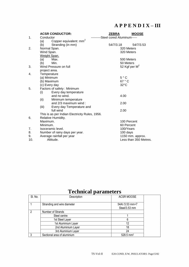
TS-Vol-II E20-COND, E/W, INSULATORS- Page15/82
A P P E N D I X – III
ACSR CONDUCTOR: ZEBRA MOOSE 1. Conductor ---------Steel cored Aluminum----- (a) Copper equivalent: mm
2
(b) Stranding (in mm) 54/7/3.18 54/7/3.53 2. Normal Span. 320 Meters Wind Span. 320 Meters Weight Span. (a) Max. 500 Meters (b) Min. 50 Meters 3. Wind Pressure on full 52 Kgf per M
2
project area. 4. Temperature (a) Minimum 5 ° C (b) Maximum 67 ° C (c) Every day 32°C 5. Factors of safety : Minimum (i) Every day temperature and no wind. 4.00 (ii) Minimum temperature and 2/3 maximum wind : 2.00 (iii) Every day Temperature and full wind 2.00 This is as per Indian Electricity Rules, 1956. 6. Relative Humidity. Maximum. 100 Percent Minimum. 60 Percent 7. Isoceramic level. 100/Years 8. Number of rainy days per year. 100 days 9. Average rainfall per year 1150 mm. approx. 10. Altitude. Less than 350 Metres.
Technical parameters Sl. No. Description ACSR MOOSE
1 Stranding and wire diameter 54Al /3.53 mm+7 Steel/3.53 mm
2 Number of Strands
Steel centre 1
1st Steel Layer 6
1st Aluminium Layer 12
2nd Aluminium Layer 18
3rd Aluminium Layer 24
3 Sectional area of aluminium 528.5 mm2

TS-Vol-II E20-COND, E/W, INSULATORS- Page16/82
4 Total sectional area 597.00 mm2
5 Overall diameter 31.77 mm
6 Approximate weight 2004 kg/km
7 Calculated DC resistance at 2O oC 0.05596 /km
8 Minimum UTS 161.2 kN
9 The details of aluminium strand are as follows:
Minimum breaking load of strand before stranding 1.57 kN
Minimum breaking load of strand after stranding 1.49 kN
Maximum DC resistance of strand at 2O oC 2.921/km
10 The details of steel strand are as follows
Minimum breaking load of strand before stranding 12.86 kN
Minimum breaking load of strand after stranding 12.22 kN
11 Minimum number of twist to be with stood in torsion test when tested on a gauge length of 100 times diameter of wire
18 - before stranding 16 - after stranding
12 Tolerances
12a Diameter of aluminium strands Standard
3.53 mm
Maximum 3.55 mm
Minimum 3.51 mm
Diameter of steel strands Standard
3.53 mm
Maximum 3.60 mm
Minimum 3.46 mm
13 Lay ratio of Conductor
13a Steel - 6 wire layer Maximum
18
Minimum 16
13b Aluminium - 12 wire layer Maximum
14
Minimum 12
13c Aluminium - 18 wire layer Maximum
13
Minimum 11
13d Aluminium - 24 wire layer Maximum
12
Minimum 11
14 Materials composition
14a Aluminium 99.5% with copper content less than 0.4%
14b Steel Carbon
0.50 to 0.85 %
Manganese 0.50 to 1.10 %
Phosphorous not more than 0.035 %
Sulphur not more than 0.045 %
Silicon 0.10 to 0.35 %
14c Zinc for galvanising electrolytic high grade zinc of 99.95% purity conforming to IS 209-1979.
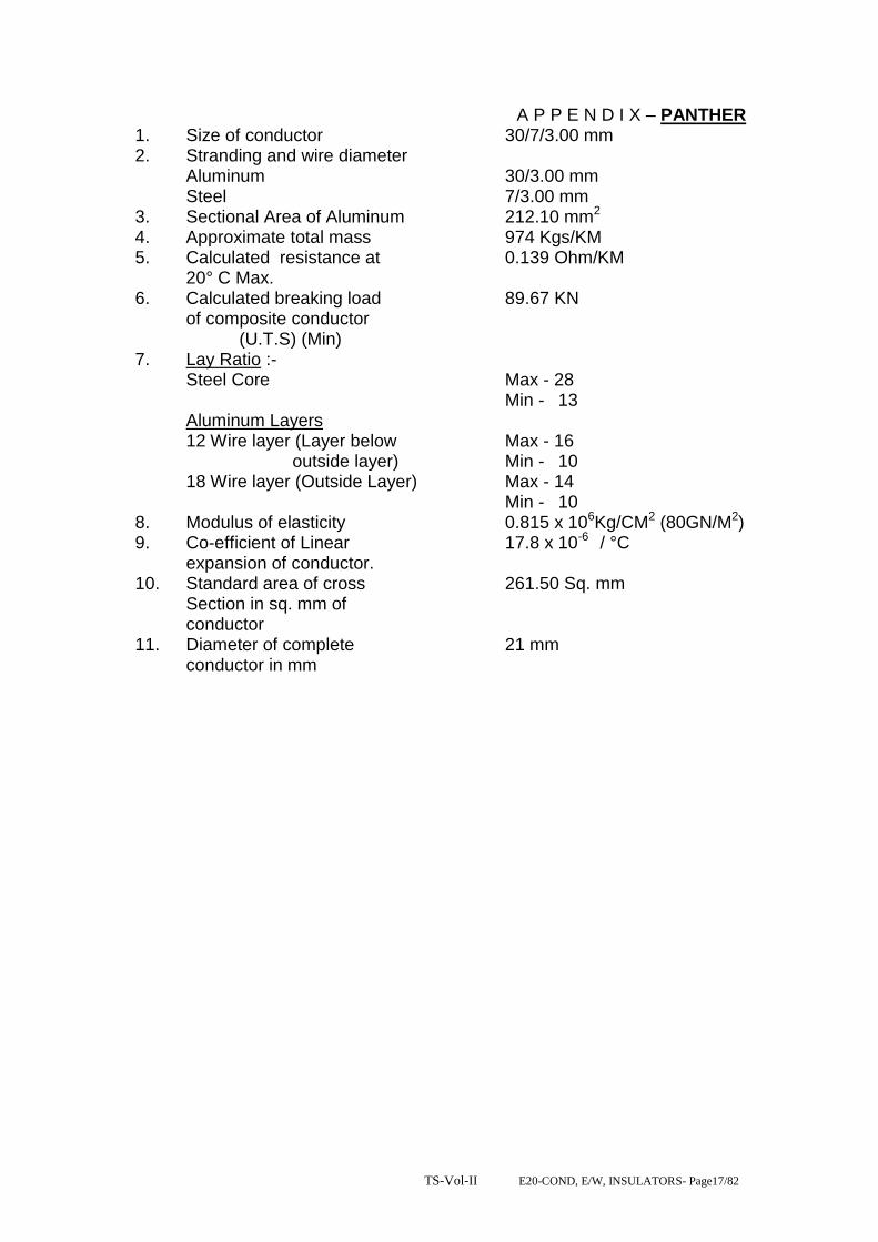
TS-Vol-II E20-COND, E/W, INSULATORS- Page17/82
A P P E N D I X – PANTHER 1. Size of conductor 30/7/3.00 mm 2. Stranding and wire diameter Aluminum 30/3.00 mm Steel 7/3.00 mm 3. Sectional Area of Aluminum 212.10 mm2
4. Approximate total mass 974 Kgs/KM 5. Calculated resistance at 0.139 Ohm/KM 20° C Max. 6. Calculated breaking load 89.67 KN of composite conductor (U.T.S) (Min) 7. Lay Ratio :- Steel Core Max - 28 Min - 13 Aluminum Layers 12 Wire layer (Layer below Max - 16 outside layer) Min - 10 18 Wire layer (Outside Layer) Max - 14 Min - 10 8. Modulus of elasticity 0.815 x 10⁶Kg/CM2 (80GN/M2) 9. Co-efficient of Linear 17.8 x 10⁻⁶ / °C expansion of conductor. 10. Standard area of cross 261.50 Sq. mm Section in sq. mm of conductor 11. Diameter of complete 21 mm conductor in mm

TS-Vol-II E20-COND, E/W, INSULATORS- Page18/82
A P P E N D I X - II
PANTHER
Solid Steel and Aluminium Wires used in Steel cored
Aluminium Conductors
1. Diameter Steel Aluminum
Standard 3.00 mm 3.00 mm
Maximum 3.06 mm 3.03 mm
Minimum 2.94 mm 2.97 mm
2. Cross Sectional Area
of nominal Diameter Wire 7.069 mm2 7.069 mm2
3. Weight 55.13 Kg/KM 19.11Kg/Km
4. Minimum tensile strength 134Kg/mm2 16.87Kg/mm2
5. Minimum breaking load 9.29 KN 1.17 KN
before stranding
6. Minimum breaking load 8.83 KN 1.11 KN
after stranding
7. Zinc coating of steel strands
No and duration of dips 3 (1 Min. dip)
Minimum Weight of As per IS 4826-1979
coating
8. Maximum resistance at 4.079 Ohms/KM
20°C of Aluminum strands
9. Purity of aluminum rod 99.5%

TS-Vol-II E20-COND, E/W, INSULATORS- Page19/82
A P P E N D I X - III
PANTHER
1. Conductor Steel cored Aluminum
(a) Copper equivalent 130 mm2
(b) Stranding 30/7/3.00 mm
2. Normal Span. 320 Meters
Wind Span. 320 Meters
Weight Span.
(a) Max. 500 Meters
(b) Min. 50 Meters
3. Wind Pressure on full 52 Kgf per M2
projected area.
4. Temperature
(a) Minimum 5 °C
(b) Maximum 67°C
(c) Every day 32°C
5. Factors of safety : Minimum
(i) Every day temperature
and no wind. 4.00
(ii) Minimum temperature
and 2/3 maximum wind : 2.00
(iii) Every day Temperature and
full wind 2.00
This is as per Indian Electricity Rules, 1956.
6. Relative Humidity.
Maximum. 100 Percent
Minimum. 60 Percent
7. Isoceramic level 100/years
8. Number of rainy days per year. 100 days
9. Average rainfall per year 1150 mm. approx.
10. Altitude. Less than 350 Meters

TS-Vol-II E20-COND, E/W, INSULATORS- Page20/82
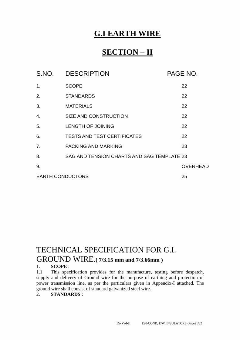
TS-Vol-II E20-COND, E/W, INSULATORS- Page21/82
G.I EARTH WIRE
SECTION – II
S.NO. DESCRIPTION PAGE NO.
1. SCOPE 22
2. STANDARDS 22
3. MATERIALS 22
4. SIZE AND CONSTRUCTION 22
5. LENGTH OF JOINING 22
6. TESTS AND TEST CERTIFICATES 22
7. PACKING AND MARKING 23
8. SAG AND TENSION CHARTS AND SAG TEMPLATE 23
9. OVERHEAD
EARTH CONDUCTORS 25
TECHNICAL SPECIFICATION FOR G.I.
GROUND WIRE.( 7/3.15 mm and 7/3.66mm ) 1. SCOPE :
1.1 This specification provides for the manufacture, testing before despatch,
supply and delivery of Ground wire for the purpose of earthing and protection of
power transmission line, as per the particulars given in Appendix-I attached. The
ground wire shall consist of standard galvanized steel wire.
2. STANDARDS :

TS-Vol-II E20-COND, E/W, INSULATORS- Page22/82
2.1 The ground wire shall comply in all respect with the Indian Standard (IS)
2141-1979
3. MATERIALS :
3.1 The material offered shall be of best quality and workmanship. The steel wires
(Strands) shall be manufactured from steel produced by any suitable process. The
steel wire shall not contain sulphur and phosphorous exceeding 0.040 percent each as
per IS : 2141-1971.
3.2 The steel wires shall be evenly and uniformity quoted with zinc complying
with IS: 209-1965 specification for zinc (Retired). Only virgin zinc shall be used and
reclaimed zinc is not permitted. The virgin zinc shall be of zn 99.95 percent quality.
3.3 The content of carbon shall not be more than 0.55 percent, manganese and
silicon contents shall be 0.40 to 0.90 and 0.15 to 0.35 respectively.
4. SIZE AND CONSTRUCTION :
4.1 The size of ground wire shall be as given in Appendix-I. The physical
properties have been given in the same Appendix. The lay of the strands shall be of
lengths as given in the Appendices. The wires shall be so stranded together that when
any evenly distributed pulls applied at the end of the completed strands each wire will
take on equal share of the pull.
5. LENGTH OF JOINING:
5.1 The ground wire may be supplied in the standard length as per manufacturers
standard practice and such length will be specifically indicated in the tender. However
random length of ground wire upto a maximum of 10 (Ten) percent may be allowed.
5.2 The length of strand which may be supplied without joints in the individual
wires comprising it depends on the length of wire which may be carried by the bobbin
in a normal stranding machine. The normal lengths of strand which shall be supplied
without joints in individual wires, excluding welds made in the rod before drawing
shall be as given in Appendix – I.
5.3 Each coil shall be warranted to contain no weld joints or splice ether than in
the rod before it is drawn and those permitted in 5.3 above. The wire shall be circular
and shall be free from scale or irregularities, imperfections, flow spite and other
defects. The zinc coating shall be smooth even and bright.
6. TESTS AND TEST CERTIFICATES:
6.1 Ground wire shall be subjected to the tests as specified in the IS:2141-1979
before despatch.
6.2 Al the coils of the galvanized strand shall be of the same grade, diameter and
construction manufactured under similar condition shall be grounded to constitute one
lot.
6.3 Samples from each lot shall be tested for ascertaining the conformity to the
requirements of the ground wire specified herein. The coils selected shall be tested for
length of the lay and joints. The lot shall be declared conforming to the requirements
of these characteristics if all the coils are found satisfactory. One test specimen from
each wire of the strand shall be drawn, from every selected coil and subjected to tensil
tests, ductility test and coating test. One specimen of the completed strand from each
coil shall be subjected to tensil strength. The lot shall be declared conforming to the
requirements of these characteristics if the entire best specimen satisfy the relevant
requirements.
6.4 Chemical Analysis : One sample shall be drawn from the lot for chemical
analysis. Unless otherwise agreed to between the purchase and supplier the chemical
analysis shall be carried out.

TS-Vol-II E20-COND, E/W, INSULATORS- Page23/82
6.5 Tensile Test : The wire when tested in accordance with IS : 1521-1960 shall
have minimum tensile strength specified in the Appendix – I. The tensile strength of
the finished strand shall not be less than 95% of the aggregate of the single wires.
6.6 Ductility test : The wire shall be subjected to wrapping test in accordance
with IS : 1755-1961. When wrapped eight times round its own diameter and on being
subsequently straightened the wire shall not break or split.
6.7 Coating test : The uniformity of zinc coating shall be tested as per IS: 2633-
1964. The wire shall withstand the number of dips specified in Appendix – I.
6.8 Three copies of manufacturers test certificate shall be submitted by the
contractor to the purchaser for approval immediately after such tests have been
conducted on the strands and the wire.
6.9 The purchaser reserves the right to inspect the material at Manufacturer‟s
works before despatch.
7. PACKING AND MARKING :
7.1 The ground wire shall be supplied in non-returnable reals or drums of non-
perishable or treated wood conforming to IS: 1778-1991 specification for Reals and
Drums for Bare wire. Each coil shall be provided with a level fixed firmly on the
inner part of the coil, bearing the following information.
(a) Trade name, if any.
(b) Name of manufacturer
(c) Type of wire, size and length of wire.
(d) Not weight of the wire.
(e) Total weight, and
(f) Number of lengths on the real or drum unless otherwise agreed to between the
purchaser and the supplier, the stranded wire shall be supplied in 50 Kg. coil.
8. SAG AND TENSION CHARTS AND SAG TEMPLATE :
8.1 The successful tenderer shall be required to submit six copies of sag templates
and strings charts for different temperatures and spans, One set of charts shall be ink
on tracing cloth. The design date of the lines on which the ground wire will be used
are given in Appendix – II
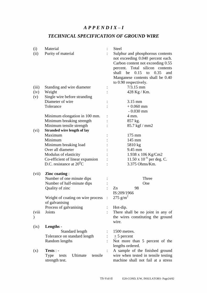
TS-Vol-II E20-COND, E/W, INSULATORS- Page24/82
A P P E N D I X – I
TECHNICAL SPECIFICATION OF GROUND WIRE
(i) Material : Steel
(ii) Purity of material : Sulphur and phosphorous contents
not exceeding 0.040 percent each.
Carbon content not exceeding 0.55
percent. Total silicon contents
shall be 0.15 to 0.35 and
Manganese contents shall be 0.40
to 0.90 respectively.
(iii) Standing and wire diameter : 7/3.15 mm
(iv) Weight : 428 Kg / Km.
(v) Single wire before stranding
Diameter of wire : 3.15 mm
Tolerance : + 0.060 mm
- 0.030 mm
Minimum elongation in 100 mm. : 4 mm.
Minimum breaking strength : 857 kg.
Minimum tensile strength : 85.7 kgf / mm2
(vi) Stranded wire length of lay
Maximum : 175 mm
Minimum : 145 mm
Minimum breaking load : 5810 kg
Over all diameter : 9.45 mm
Modulus of elasticity : 1.938 x 10⁶ Kg/Cm2
Co-efficient of linear expansion : 11.50 x 10⁻⁶
per deg. C.
D.C. resistance at 200C : 3.375 Ohms/Km.
(vii) Zinc coating :
Number of one minute dips : Three
Number of half-minute dips : One
Quality of zinc : Zn 98
IS:209/1966
Weight of coating on wire process
of galvanising
: 275 g/m2
Process of galvanising : Hot-dip.
(viii
)
Joints : There shall be no joint in any of
the wires constituting the ground
wire.
(ix) Lengths -
Standard length : 1500 metres.
Tolerance on standard length : + 5 percent
Random lengths : Not more than 5 percent of the
lengths ordered.
(x) Tests : -
Type tests Ultimate tensile
strength test.
: A sample of the finished ground
wire when tested in tensile testing
machine shall not fail at a stress
TS-Vol-II E20-COND, E/W, INSULATORS- Page25/82
less than 100% of UTS value of
the ground wire. The length of the
test sample shall be not less than 5
meters.
Electrical Tests : As per BS : 182/1972 and BS :
3229/1960
Routine Tests : As per clause No. 6 of IS: 2141
1968. In addition to these tests, the
weight and adherence of Zinc
coating tests shall be conducted as
per clause 4 and 5 of IS :
4826/1968.
(xi) Test Reports : Three copies of manufacturer test
certificates shall be submitted by
the Contracts to the purchaser for
approve immediately after such
test have been conducted on the
galvanised steel strand and the
wire.
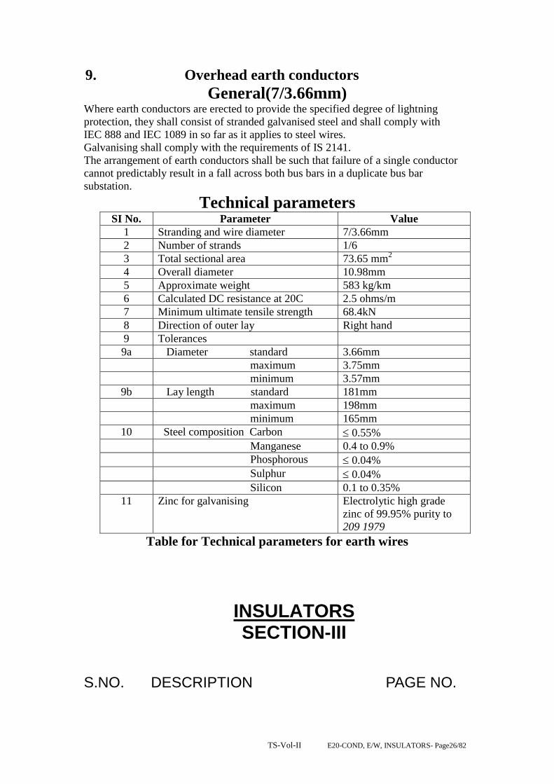
TS-Vol-II E20-COND, E/W, INSULATORS- Page26/82
9. Overhead earth conductors
General(7/3.66mm) Where earth conductors are erected to provide the specified degree of lightning
protection, they shall consist of stranded galvanised steel and shall comply with
IEC 888 and IEC 1089 in so far as it applies to steel wires.
Galvanising shall comply with the requirements of IS 2141.
The arrangement of earth conductors shall be such that failure of a single conductor
cannot predictably result in a fall across both bus bars in a duplicate bus bar
substation.
Technical parameters SI No. Parameter Value
1 Stranding and wire diameter 7/3.66mm
2 Number of strands 1/6
3 Total sectional area 73.65 mm2
4 Overall diameter 10.98mm
5 Approximate weight 583 kg/km
6 Calculated DC resistance at 20C 2.5 ohms/m
7 Minimum ultimate tensile strength 68.4kN
8 Direction of outer lay Right hand
9 Tolerances
9a Diameter standard 3.66mm
maximum 3.75mm
minimum 3.57mm
9b Lay length standard 181mm
maximum 198mm
minimum 165mm
10 Steel composition Carbon 0.55%
Manganese 0.4 to 0.9%
Phosphorous 0.04%
Sulphur 0.04%
Silicon 0.1 to 0.35%
11 Zinc for galvanising Electrolytic high grade
zinc of 99.95% purity to
209 1979
Table for Technical parameters for earth wires
INSULATORS SECTION-III
S.NO. DESCRIPTION PAGE NO.

TS-Vol-II E20-COND, E/W, INSULATORS- Page27/82
1. SCOPE
2. STANDARDS
3. PRINCIPAL PARAMETERS
4. GENERAL TECHNICAL REQUIREMENTS
5. DETAILS OF SOLID CORE ROD INSULATORS
6. SPECIFICATION DRAWINGS
7. GENERAL TECHNICAL REQUIREMENTS
8. MATERIAL DESIGN AND WORKMANSHIP
9. TESTS (FOR DISC INSULATORS)
10 INSPECTION
11. QUALITY ASSURANCE PLAN
12. TEST DETAILS
INSULATORS
TECHNICAL SPECIFICATION FOR DISC INSULATORS FOR SUBSTATION AND TRANSMISSION LINE WORK
1.0 SCOPE.
1.1 This specification provides for design, manufacture, engineering, inspection and testing before despatch packing and delivery FOR (destination) for Indian manufacturers of disc. Insulators as per technical requirements furnished in this specification.
These insulators are to be used in suspension and tension insulators strings for the suspension and anchoring of the conductors on EHV transmission line towers.

TS-Vol-II E20-COND, E/W, INSULATORS- Page28/82
1.2 Following is the list of documents constituting this package. (i) Technical specification. (ii) Technical data sheet. (iii) Drawings of insulators (ii) 1.3 All the above volumes along with amendments there of shall be read and interpreted together. However, in case of a contradiction between the “Technical Specification” and any other volume, the provisions of this volume will prevail.
1.4 The insulators shall conform in all respects to high standards of engineering, design workmanship and latest revisions of relevant standards at the time of offer and purchaser shall have the power to reject any work or material which in his judgment, is not in full accordance therewith.
2.0 STANDARDS: 2.1 Except as modified in this specification, the disc insulators shall conform to the following Indian Standards, which shall mean latest revisions and amendments. Equivalent International and Internally recognized standards to which some of these standards generally correspond are also listed below.
Sl. No.
Indian Standard
Title. International Standard.
1. IS: 206 Method for Chemical Analysis of Slab Zinc.
2. IS: 209
Specification for Zinc. BS: 3436
3. IS: 731 Porcelain insulators for overhead power lines with a normal voltage greater than 1000V
BS: 137(I&II); IEC 274 IEC 383
4. IS: 2071 Part-(I) Part-(II) Part-(III)
Method of High Voltage Testing.
5. IS: 2121 (Part-I)
Specification of Conductors and Earth wire Accessories for Overhead Power lines. Armour Rods, Binding wires and tapes for conductor.
6. IS: 2486 Specification for Insulator fittings for overhead power lines with a nominal voltage greater than 1000V.
Part – I General Requirement and Tests.
BS: 3288
Part – II Dimensional Requirements. IEC: 120
Part – III Locking devices. IEC: 372
7. IS: 2629 Recommended practice for Hot Dip Galvanisation for iron
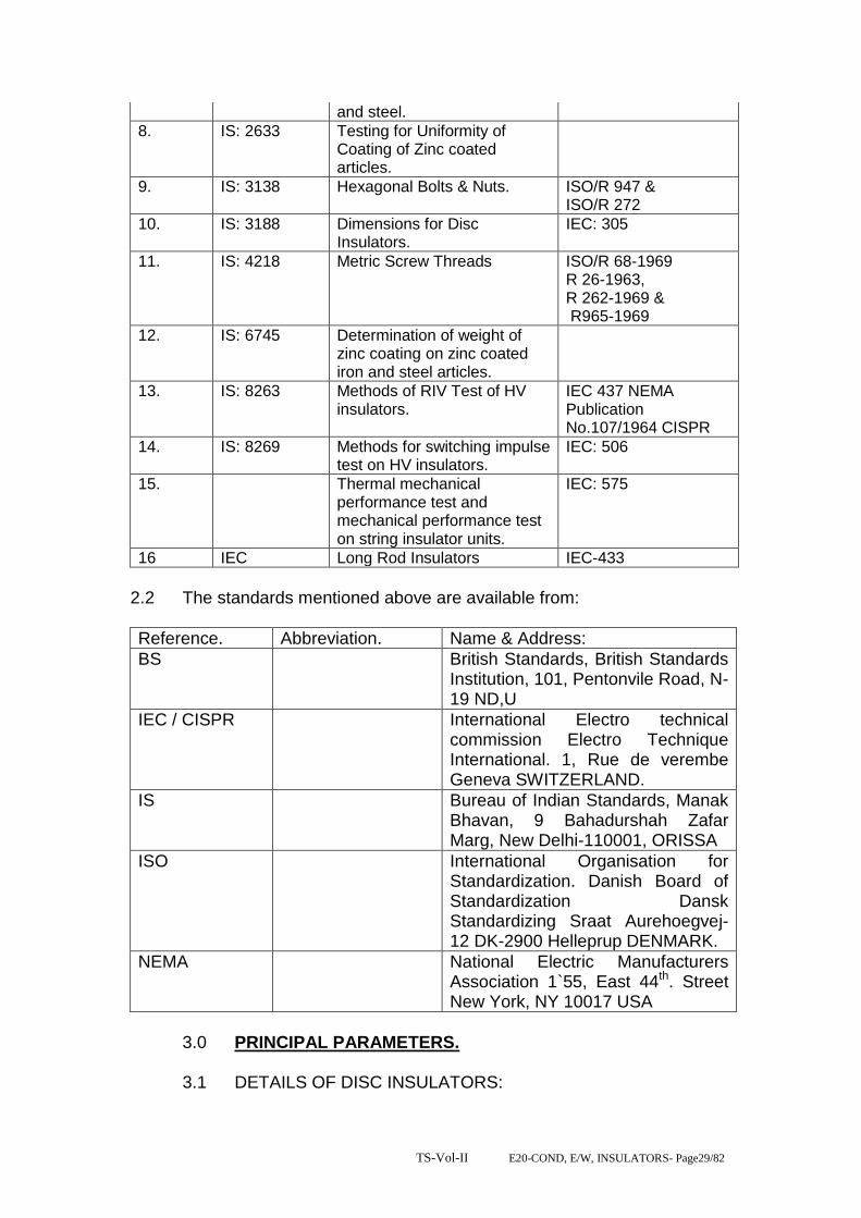
TS-Vol-II E20-COND, E/W, INSULATORS- Page29/82
and steel.
8. IS: 2633 Testing for Uniformity of Coating of Zinc coated articles.
9. IS: 3138 Hexagonal Bolts & Nuts. ISO/R 947 & ISO/R 272
10. IS: 3188 Dimensions for Disc Insulators.
IEC: 305
11. IS: 4218 Metric Screw Threads ISO/R 68-1969 R 26-1963, R 262-1969 & R965-1969
12. IS: 6745 Determination of weight of zinc coating on zinc coated iron and steel articles.
13. IS: 8263 Methods of RIV Test of HV insulators.
IEC 437 NEMA Publication No.107/1964 CISPR
14. IS: 8269 Methods for switching impulse test on HV insulators.
IEC: 506
15. Thermal mechanical performance test and mechanical performance test on string insulator units.
IEC: 575
16 IEC Long Rod Insulators IEC-433
2.2 The standards mentioned above are available from:
Reference. Abbreviation. Name & Address:
BS British Standards, British Standards Institution, 101, Pentonvile Road, N-19 ND,U
IEC / CISPR International Electro technical commission Electro Technique International. 1, Rue de verembe Geneva SWITZERLAND.
IS Bureau of Indian Standards, Manak Bhavan, 9 Bahadurshah Zafar Marg, New Delhi-110001, ORISSA
ISO International Organisation for Standardization. Danish Board of Standardization Dansk Standardizing Sraat Aurehoegvej-12 DK-2900 Helleprup DENMARK.
NEMA National Electric Manufacturers Association 1`55, East 44th. Street New York, NY 10017 USA
3.0 PRINCIPAL PARAMETERS. 3.1 DETAILS OF DISC INSULATORS:

TS-Vol-II E20-COND, E/W, INSULATORS- Page30/82
3.1.1 The Insulator strings shall consist of standard discs for use in three phases. 50 Hz effectively earthed 33/132/220 KV transmission system of OPTCL in a moderately polluted atmosphere. The discs shall be cap and pin, ball and socket type, radio interference and have characteristics as shown in Table-I and all ferrous parts shall be hot dip galvanized as per the latest edition of IS 2629. The zinc to be used for making sleeves shall be 99.95 % pure.
3.1.2 The size of disc insulator, minimum creepage distance the number to be used in different type of strings, their electromechanical strength and mechanical strength 3.1.3 of insulator string along with hardware shall be as follows: PRINCIPAL PARAMETERS OF THE DISC INSULATORS:-
Sl. No.
Type of String.
Size of disc. Insulator (mm)
Minimum creepage distance of each disc (mm),
No. of standard discs 132 KV /220/400 KV
Electro-mechanical strength of insulator string fittings (KN)
1. Single suspension
255 x 145 320 1x9/1x14 70 KN/90 KN Normal Disc Insulator
2. Double suspension.
-do- -do- 2x9/2x14 70 KN/90 KN Normal Disc Insulator
3 Single suspension
255 x 145 430 1x9/1x14 70 KN/90 KN Antifog Insulator
4 Double suspension.
-do- -do- 2x9/2x14 70 KN/90 KN Antifog Disc Insulator
5 Single Tension
280x145 430 1x10/1x15 120 KN Antifog Disc Insulator
6 Double Tension
-do- -do- 2x10/2x15 120 KN Antifog Disc Insulator
7 Single Tension
305x170 475 1x10/1x15/1x25
160 KN Antifog Disc Insulator
8 Double Tension
-do- -do- 2x10/2x15/2x25
160 KN Antifog Disc Insulator
5 Single Suspension
280x145 430 1x10/1x15/1X25
120 KN Antifog Disc Insulator
6 Double Suspension
-do- -do- 2x10/2x15/2X25
120 KN Antifog Disc Insulator
3.2 SPECIFICATION DRAWINGS: 3.2.1 The specification in respect of the disc insulators are described.These
specification for information and guidance of the Bidder only. The drawings to be furnished by the supplier shall be as per his own design and manufacture and in line with the specification.
4.0 GENERAL TECHNICAL REQUIREMENTS: 4.1 Porcelain:

TS-Vol-II E20-COND, E/W, INSULATORS- Page31/82
The porcelain used in the manufacture of the shells shall be ivory white nonporous of high dielectric, mechanical and thermal strength, free from internal stresses blisters, laminations, voids, forgone matter imperfections or other defects which might render it in any way unusable for insulator shells. Porcelain shall remain unaffected by climatic conditions ozone, acid, alkalis, zinc or dust. The manufacturing shall be by the wet process and impervious character obtained by through vetrification. The insulator shall be made of highest grade, dense, homogeneous, wet-process porcelain, completely and uniformly vitrified throughout to produce uniform mechanical and electrical strength and long life service. The porcelain shall be free from warping, roughness, cracks, blisters, laminations, projecting points foreign particles and other defects, except those within the limits of standard accepted practice. Surfaces and grooves shall be shaped for easy cleaning. Shells shall be substantially symmetrical. 4.1.1 Porcelain glaze: Surface to come in contact with cement shall be made rough by stand glazing. All other exposed surfaces shall be glazed with ceramic materials having the same temperature coefficient of expansion as that of the insulator shell. The thickness of the glaze shall be uniform throughout and the colour of the glaze shall be down. The Glaze shall have a visible luster and smooth on surface and be capable of satisfactory performance under extreme tropical climatic weather conditions and prevent ageing of the porcelain. The glaze shall remain under compression on the porcelain body through out the working temperature range.
4.2 METAL PARTS: 4.2.1 Cap and Ball Pins:
Ball pins shall be made with drop forged steel caps with malleable cast iron. They shall be in one single piece and duly hot dip galvanized. They shall not contain parts or pieces joined together welded, shrink fitted or by any other process from more than one piece of materials. The pins shall be of high tensile steel, drop forged and heat-treated. The caps shall be cast with good quality black heart malleable cast iron and annealed. Galvanizing shall be by the hot dip process with a heavy coating of zinc of very high purity. The bidder shall specify the grade composition and mechanical properties of steel used for caps and pins. The cap and pin shall be of such design that it will not yield or distort under the specified mechanical load in such a manner as to change the relative spacing of the insulators or add other stresses to the shells. The insulator caps shall be of the socket type provided with nonferrous metal or stainless steel cotter pins and shall provide positive locking of the coupling.
4.2.2 Security Clips:

TS-Vol-II E20-COND, E/W, INSULATORS- Page32/82
The security cops shall be made of phosphor bronze or of stainless steel.
4.3 FILTER MATERIAL: Cement to be used, as a filler material be quick setting, fast curing Portland cement. It shall not cause fracture by expansion or loosening by contraction. Cement shall not react chemically with metal parts in contact with it and its thickness shall be as small and as uniform as possible.
4.4 MATERIALS DESIGN AND WORKMANSHIP: 4.4.1 GENERAL: (II) All raw materials to be used in the manufacture of these insulators shall be subject to strict raw material quality control and to stage testing/ quality control during manufacturing stage to ensure the quality of the final end product. Manufacturing shall conform to the best engineering practices adopted in the field of extra high voltage transmission. Bidders shall therefore offer insulators as are guaranteed by them for satisfactory performance on Transmission lines. (III) The design, manufacturing process and material control at various stages be such as to give maximum working load, highest mobility, best resistance to corrosion, good finish elimination of sharp edges and corners to limit corona and radio interference voltages.
4.4.2 INSULATOR SHELL:
The design of the insulator shells shall be such that stresses due to expansion and contraction in any part of the insulator shall not lead to deterioration. Shells with cracks shall be eliminated by temperature cycle test followed by mallet test. Shells shall be dried under controlled conditions of humidity and temperature.
4.4.3 METAL PARTS: i) The pin and cap shall be designed to transmit the mechanical stress to the shell by compression and develop uniform mechanical strength in the insulator. The cap shall be circular with the inner and outer surfaces concentric and of such design that it will not yield or distort under loaded conditions. The head portion of the pinball shall be suitably designed so that when the insulator is under tension the stresses are uniformly distributed over the pinhole portion of the shell. The pinball shall move freely in the cap socket either during assembly of a string or during erection of a string or when a string is placed in position. ii) Metal caps shall be free from cracks, seams, shrinks, air holes, blowholes and rough edges. All metal surfaces shall be perfectly smooth with no projecting part or irregularities, which may cause corona. All load bearing surfaces shall be smooth and uniform so as to distribute the loading stress uniformly. Pins shall not show any microscopically visible cracks, inclusions and voids.
4.4.4 GALVANIZING:
TS-Vol-II E20-COND, E/W, INSULATORS- Page33/82
All ferrous parts, shall be hot dip galvanized in accordance with IS: 2629. The zinc to be used for galvanizing shall conform to grade Zn 99.5 as per IS: 209. The zinc coating shall be uniform, smoothly adherent, reasonably light, continuous and free from impurities such as flux, ash, rust stains, bulky white deposits and blisters. Before ball fittings are galvanized, all die flashing on the shank and on the bearing surface of the ball shall be carefully removed without reducing the designed dimensional requirements.
4.4.5 CEMENTING: The insulator design shall. Be such that the insulating medium shall not directly engaged with hard metal. The surface of porcelain and coated with resilient paint to offset the effect of difference in thermal expansions of these materials. High quality Portland cement shall be used for cementing the porcelain to the cap & pin.
4.4.6 SECURITY CLIPS (LOCKING DEVICES) The security clips to be used as locking device for ball and socket coupling shall be „R‟ shaped hump type to provide for positive locking of the coupling as per IS: 2486 (Part-IV). The legs of the security clips shall allow for spreading after installation to prevent complete withdrawal from the socket. The locking device shall resilient corrosion resistant and of sufficient mechanical strength. There shall be no possibility of the locking device to be displaced or be capable of rotation, which placed in position, and under no circumstances shall it allow separation of insulator units and fittings. „W‟ type security clips are also acceptable. The hole for the security clip shall be counter sunk and the clip shall be of such design that the eye of the clip may be engaged by a hot line clip puller to provide for disengagement under energized conditions. The force required for pulling the clip into its unlocked positions shall not be less than 50 N (5 kg.) or more than 500 N (50 kgs.).
4.4.7 MARKING: Each insulator shall have the rated combined mechanical and electrical strength marked clearly on the porcelain surface. Each insulator shall also bear symbols identifying the manufacturer, month, and year of manufacture. Marking on porcelain shall be printed, not impressed, and shall be applied before firing.
4.5 BALL AND SOCKET DESIGNATION: The dimensions of the ball and sockets for 70 and 90 KN discs shall be of 16 mm and for 120 KN and 160 KN discs shall be of 20 mm designation in accordance with the standard dimensions stated in IS: 2486 (Part-II).
4.6 DIMENSIONAL TOLERANCE OF INSULATOR DISCS:
It shall be ensured that the dimensions of the disc insulators are within the limits specified below:
4.6 DIMENSIONAL TOLERANCE OF INSULATOR DISCS:

TS-Vol-II E20-COND, E/W, INSULATORS- Page34/82
It shall be ensured that the dimensions of the disc insulators are within the limits specified below:
(a)
Sl. No.
Diameter of Disc (mm) Standard in mm
Maximum Minimum
1. 70 KN/90 KN & 120 KN
255/255 & 280 As per IS As per IS
2. 160 KN 305 As per IS As per IS
(b)
Sl. No.
Ball to Ball spacing Between Discs (mm)
Standard in mm
Maximum Minimum
1. 70 KN/90 KN/120 KN 145 As per IS As per IS
2. 160 KN 170 As per IS As per IS
(C) GUARANTEED TECHNICAL PARTICULARS FOR ANTIFOG DISC INSULATORS
Sl. No.
DESCRIPTION 70 KN 90 KN
120KN 160 KN
1. Manufacture‟s name &address
2 Type of Insulator Ball & socket
Ball & socket
Ball & socket
Ball & socket
3 Size of ball & socket 16B 16B 20 20
4 Dimensions
(a) Disc diameter 255 255 280 305
(b) Unit spacing 145 145 145 170
(c) Creepage distance of the single insulator-mm
430 430 430 475
5 Electro-mechanical strength of single inslator-kN
70 90 120 160
6 Materials of shell Porcelain Porcelain Porcelain
Porcelain
Electrical value
7.
7.1 Power frequency Withstand voltage disc (a) Dry-kV (rms) (b) Wet-kV (rms)
80 45
80 45
85 50
90 50
7.2 Power frequency flash over voltage single-disc (a) Dry-kV (rms) (b) Wet-kV (rms)
85 50
85 50
90 55
95 55
7.3 Impulse withstand voltage 1.2/50 micro second 1.Positive –kV(peak) 2.Negative –kV (peak)
125 125
125 125
130 130
135 135

TS-Vol-II E20-COND, E/W, INSULATORS- Page35/82
7.4 Impulse Flashover voltage 1.2/50 micro second 1.Positive –kV(peak) 2.Negative –kV (peak)
135 130
135 130
140 135
145 140
* Tolerance as per relevant IS (Latest edition). 4.7 INTERCHANGEABILITY: The insulators inclusive of the ball and socket fittings shall be of standard design suitable for use with hardware fittings of any make conforming to relevant Indian Standards. 4.8 CORONA AND RIV PERFORMANCE: All surfaces shall be even, smooth, without cuts, abrasions or projections. No part shall be subject to excessive localized pressure. The metal parts and porcelain shall not produce any noise-generating corona under all operating conditions.
4.9 SUITABILITY FOR LIVE LINE MAINTENANCE: The insulator shall be compatible for use with hot line or live line maintenance techniques so that usual hot line operation can be carried out with easy speed and safety.
4.10 FREEDOM FROM DEFECTS: Insulators shall have none of the following defects:
1) Ball pin shake. 2) Cementing defects near the pin like small blow holes, small hair cracks lumps etc. 3) Sand fall defects on the surface of the insulator. 4.11 INSULATOR STRINGS: 4.11.1 TYPE AND RATING:
The insulator strings shall be formed with standard discs described in this specification for use on 3 phases 132/22 KV 50 Hz effectively earthed systems in an atmosphere with pollution level as indicated in project synopsis. Suspension insulator strings for use with suspension/tangent towers are to be fitted with discs 70/90 KN EMS rating while tension insulator strings for use with Anchor/ Tension towers are to be fitted with discs of 120 KN / 160 KN EMS level rating.
4.11.2 STRING SIZE: The sizes of the disc insulator, the number to be used in different types of strings, their electro-mechanical strength and minimum nominal creep age distance shall be as given in clause 3.12
4.12 STRING CHARACTERISTICS: 4.12.1 The characteristics of the complete string shall be as follows:
Sl. No.
Description. Suspension. Tension.
132KV
220kV 132KV 220KV

TS-Vol-II E20-COND, E/W, INSULATORS- Page36/82
I Switching surge withstand voltage (dry & wet) KV peak.
- - - -
Ii Lighting impulse withstand voltage (dry) KV Peak.
650 1050 650 1050
Iii Power frequency without voltage (wet) KV r.m.s.
275 460 275 460
Iv. Corona extinction voltage level KV rms
- 176 - 176
v. Max. RIV for comp. Etc. strong including corona rings at 156 KV (rms). … hours clamps etc. at 1.1. times maximum knee to ground voltage (micro volts).
- 500 - 500
vi. Mechanical failing load for each sting (kgf)
6500 11500 11500 15500
Vii. No deformation load for each string (kgf)
- 7705 - 10385
Viii. Max. voltage across any disc. 13% 13% 13% 13%
4.12.2 Insulator units after assembly shall be concentric and coaxial within limits as permitted by Indian Standards.
4.12.3 The strings design shall be such that when units are coupled together there shall be contact between the shell of one unit and metal of the adjacent unit.
5.0 DETAILS OF SOLID CORE LONG ROD INSULATORS: 5.1 The insulator shall consist of standard-discs for a three-phase 50 Hz
effectively earthed 132 KV transmission system heavily polluted atmosphere. The insulator shall be ball and socket type.
5.2 The size of long rod insulator, minimum creepage distance, the number to be used in different type of strings, their electromechanical strength and mechanical strength of insulator string along with hardware shall be as follows: Sl. No.
Type of string.
Size of long rod insulator (mm)/(Unit) 132/220 KV
Minimum creepage distance (mm) 132/220 KV
No.of unit 132/220 KV)
Electromechanical strength of insulator (KN) 132/220 KV)
1.
Single suspension
200X 1305
/210X2030
4000 /
6125
'1/2 90 KN
2.
Double suspension
-do- -do- '2/4 90 KN
3.
Single tension.
205 X 1450 /
215X2550
4300/7130 '1/2 120 KN/160 KN
4. Double -do- -do- '2/4 120 KN/160 KN

TS-Vol-II E20-COND, E/W, INSULATORS- Page37/82
Tension.
6.0 SPECIFICATION DRAWINGS: 6.1 The specification in respect of the long rod insulators indicated above
is given at Annexure-II. These specification is for information and guidance of the bidder only. The drawings to be furnished by the supplier shall be as per his own design and manufacture and shall be in line with the specification.
7.0 GENERAL TECHNICAL REQUIREMENT: 7.1 PORCELAIN: The porcelain used in the manufacture of the shell shall be ivory white, nonporous of high dielectric, mechanical and thermal strength free from internal stress blisters and thermal strength from internal stresses blisters, laminations, voids, foreign matter. Imperfections or other defects, which might render it in any way unsuitable for insulator shells. Porcelain shall remain unaffected by climatic conditions, ozone, acid alkalis, and zinc of dust. The manufacturing shall be by the wet process and impervious character obtained by through vetrification. 7.2 PORCELAIN GLAZE: Surfaces to come in contact with cement shall be made rough by stand glazing. All other exposed surfaces shall be glazed with ceramic materials having the same temperature coefficient of expansion as that of the insulator shell. The thickness of the glaze shall be uniform throughout and the colour of the glaze shall be brown. The glaze shall have a visible luster and smooth on surface and be capable of satisfactory performance under extreme tropical climatic weather conditions and prevent ageing of the porcelain. The glaze shall remain under compression on the porcelain body throughout the working temperature range. 7.3 METAL PARTS: 7.3.1 Cap and Ball pins: Twin Ball pins shall be made with drop forged steel and caps with malleable cast iron. They shall be in one single piece and duly hot dip g galvanized. They shall not contain parts or pieces joined together, welded, shrink fitted or by any other process from more than one piece of material. The pins shall be of high tensile steel, drop forged and heat malleable cast iron and annealed. Galvanizing shall be by the hot dip process with a heavy coating of zinc of very high purity with minimum of 6 dips. The bidder shall specify the grade, composition and mechanical properties of steel used for caps and pins. 7.3.2 SECURITY CLIPS: The security clips shall be made of phosphor bronze or of stainless steel. 7.4 FILLER MATERIAL:
TS-Vol-II E20-COND, E/W, INSULATORS- Page38/82
Cement to be used as a filler material shall be quick setting, for curing Portland cement. It shall not cause fracture by expansion or loosening by contraction. Cement shall not react chemically with metal parts in contract with it and its thickness shall be as small and as uniform as possible.
8.0 MATERIAL DESIGN AND WORKMANSHIP: 8.1 GENERAL:
i) All raw materials to be used in the manufacture of these insulators shall be subject to strict raw materials quality control and to stage testing quality control during manufacturing stage to ensure the quality of the final end product. Manufacturing shall conform to the best engineering practices adopted in the field of extra high voltage transmission. Bidders shall therefore offer insulators as are guaranteed by them for satisfactory performance on Transmission lines. ii) The design, manufacturing process and material control at various stages be such as to give maximum working load, highest mobility, best resistance to corrosion good finish, elimination of sharp edges and corners to limit corona and radio interference voltage
8.2 INSULATOR SHELL:
The design of the insulator shell shall be such that stresses due to expansion and contraction in any part of the insulator shall not lead to deterioration. Shells with cracks shall be eliminated by temperature cycle test followed by temperature cycle test followed by mallet test. Shells shall be dried under controlled conditions of humidity and temperature.
8.3 METAL PARTS: i) The twin ball pin and cap shall be designed to transmit the mechanical stresses to the shell by compression and develop uniform mechanical strength in the insulator. The cap shall be circular with the inner and outer surfaces concentric and of such design that it will not yield or distort under loaded conditions. The head portion of the insulator or is under tension the stresses are uniformly distributed over the pinhole portion of the shell. The pinball shall move freely in the cap socket either during assembly of a string or during erection of a string or when a string is placed in position. ii) Metal caps shall be free from cracks, seams, shrinks, air holes, blowholes and rough edges. All metal surfaces shall be perfectly smooth with no projecting parts or irregularities which may cause corona. All load bearing surfaces shall be smooth and uniform so as to distribute the loading stresses uniformly. Pins shall not show any macroscopically visible cracks, insulations and voids.
8.4 GALVANIZING:
All ferrous parts shall be hot dip galvanized six times in accordance with IS: 2629. The zinc to be used for galvanizing shall conform to grade Zn 99.5 as per IS: 209. The zinc coating shall be uniform, smoothly adherent, reasonably light, continuous and free from

TS-Vol-II E20-COND, E/W, INSULATORS- Page39/82
impurities such as flux ash, rust stains, bulky white deposits and blisters. Before ball fittings are galvanized, all die flashing on the shank and on the bearing surface of the ball shall be carefully removed without reducing the designed dimensional requirements.
8.4.1 CEMENTING: The insulator design shall be such that the insulating medium shall not directly engage with hard metal. The surfaces of porcelain and coated with resilient paint to offset the effect of difference in thermal expansions of these materials.
8.5 SECURITY CLIPS (LOCKING DEVICES The security clips to be used as locking device for ball and socket coupling shall be „R‟ shaped hump type to provide for positive locking of the coupling as per IS: 2486 (Part-IV). The legs of the security clips shall allow for sore adding after installation to prevent complete withdrawal from the socket. The locking device shall be resilient corrosion resistant and of sufficient mechanical strength. There shall be no possibility of the locking device to be displaced or be capable of rotation when placed in position and under no circumstances shall it allow separation of insulator units and fitting „W‟ type security clips are also acceptable. The hole for the security clip shall be countersunk and the clip shall be of such design that the eye of the clip may be engaged by a hot line clip puller to provide for disengagement under energized conditions. The force required for pulling the clip into its unlocked position shall not be less than 50 N (5 Kgs.) or more than 500N (50 Kgs.)
8.6 BALL AND SOCKET DESIGNATION: The dimensions of the balls and sockets for 80 KN long rod insulators shall be of 16mm and for 120 KN shall be of 20mm designation in accordance with the standard dimensions stated in IS: 2486 (Part-III).
8.7 DIMENSIONAL TOLERANCE OF INSULATORS DISCS It shall be ensured that the dimensions of the long rod insulators are within the limits as per relevant IEC/ISS.
9.0 TESTS (FOR DISC INSULATORS) : 9,1 The following tests shall be carried out on the insulator string and disc
insulators.
9.2 TYPE TEST: This shall mean those tests, which are to be carried out to prove the design, process of manufacture and general conformity of the material and product with the intents of this specification. These tests shall be conducted on a representative number of samples prior to commencement of commercial production. The Bidder shall indicate his schedule for carrying out these tests.

TS-Vol-II E20-COND, E/W, INSULATORS- Page40/82
9.3 ACCEPTANCE: This shall mean these tests, which are to be carried out on samples taken from each lot offered for pre-despatch inspection for the purpose of acceptance of the lot.
9.4 ROUTINE TESTS: This shall mean those tests, which are to be carried out on each insulator to check the requirements, which are likely to vary during production.
9.5 TESTS DURING MANUFACTURE: Stage tests during manufacture shall mean those tests, which are to be carried out during the process of manufacture to ensure quality control such that the end product is of the designed quality conforming to the intent of this specification.
9.6 TEST VALUE: For all type and acceptance tests the acceptance values shall be the value guaranteed by the bidder in the guaranteed technical particulars of the acceptance value specified in this specification of the relevant standard whichever is more stringent for that particular test.
9.7 TEST PROCEDURE AND SAMPLING NORMS: The norms and procedure of sampling for the above tests shall be as per the relevant Indian Standard or the Internationally accepted standards. This will be discussed and mutually agreed to between the supplier and purchaser before placement of order. The standards and normal according to which these tests are to be carried out are listed against each test. Where a particular test is a specific requirement of this specification, the norms land procedure for the same shall be as specified in Annexure-IV attached hereto as mutually agreed to between the supplier and the purchaser in the quality assurance programme.
9.8 TYPE TESTS: The following type test shall be conducted on a suitable number of individual unit components, materials or complete strings.
9.8.1 On the complete insulator string with hardware fittings. a) Power frequency voltage withstand test with
corona control rings and under wet condition. : BS:137(Part-I)
b) Switching surge voltage withstand test under wet condition (400 only)
:
c) Impulse voltage withstand test under dry condition.
: IEC: 383
d) Impulse voltage flashover test under dry condition.
:
e) Voltage distribution test. : f) Corona & RIV test under dry condition. : As per this
specification. g) Mechanical strength test. : As per this

TS-Vol-II E20-COND, E/W, INSULATORS- Page41/82
specification. h) Vibration. : 9.8.2 On Insulators: a) Verification of dimensions. : IS: 731 b) Thermal mechanical performance test: : IEC:575 c) Power frequency voltage withstand and
flashover (I) dry (ii) wet.
: BS: 173
d) Impulse voltage withstand flashover test (dry) : IEC: 383 e) Visible discharge test (dry) : IS:731 f) RIV test (dry) : IS:8263 9.8.3 All the type tests given under clause No.6.8.1
above shall be conducted on single suspension and Double Tension insulator string alongwith hardware fittings.
9.9 ACCEPTANCE TESTS: 9.9.1 For insulator: a) Visual examination : IS:731 b) Verification of dimensions. : IS:731 c) Temperature cycle test. : IS:731 d) Galvanizing test. : IS:731 e) Mechanical performance test. : IEC:575 f) Test on locking device for ball and socket
coupling. : IEC:372
g) Eccentricity test. : As per this specification.
h) Electro-mechanical strength test. : i) Puncture test. : IS:731 j) Porosity test. : IS:731 9.10 ROUTINE TESTS: 9.10.1
For insulators:
a) Visual inspection. : IS:731 b) Mechanical routine test. : c) Electrical routine test. : IEC:383 9.11 TEST DURING MANUFACTURE: On all components as applicable. a) Chemical analysis of zinc used for
galvanizing. :
b) Chemical analysis, mechanical and metallographic test and magnetic particle inspection for malleable castings.
:
c) Chemical analysis, hardness test and magnetic particle inspection for forgings.
: As per this specification.
d) Hydraulic Internal Pressure tests on shell. : e) Crack detection test for metal parts. :
9.12 ADDITIONAL TEST:

TS-Vol-II E20-COND, E/W, INSULATORS- Page42/82
The purchaser reserves the right for carrying out any other tests of a reasonable nature at the works of the supplier/ laboratory or at any other recognized laboratory/ research institute in addition to the above mentioned type, acceptance and routine tests at the cost of the purchaser to satisfy that the material complies with the intent of this specification.
9.13 CO-ORDINATION FOR TESTING: For insulator strings, the supplier shall arrange to conduct testing of their disc insulators with the hardware fittings to be supplied to the purchaser by other suppliers. The supplier is also required to guarantee overall satisfactory performance of the disc insulator with the hardware fittings. NOTE: In respect of electrical tests on a complete string consisting of insulators and hardware guarantee of values of responsibility of testing shall be with hardware manufacturer of RIV corona and voltage distribution test and with insulator manufacturer for all other tests.
9.14 TEST CHARGES AND TEST SCHEDULE: 9.14.1 TYPE TEST:
The insulator offered shall be fully type tested as per this specification. In case the equipment of the type and design offered, has already been type tested in an independent test laboratory. The bidder shall furnish four sets of type test reports alongwith the offer. These tests must not have been conducted earlier than five years. The purchaser reserves the right to demand repetition of some or all type tests in the presence of purchasers‟ carrying representative. For this purpose the bidder may quote unit rates for carrying out each type test. These prices shall be taken into consideration for bid evaluation. For any change in the design/type already type tested and the design/type offered against this specification, purchaser reserves the right to demand repetition of tests without any extra cost.
9.14.2 ACCEPTANCE AND ROUTINE TEST: All acceptance and routine tests as stipulated herein shall be carried out by the supplier in the presence of purchaser‟s representative.
9.14.3 Immediately after finalisation of the programme of type/ acceptance/ routine testing, the supplier shall give sufficient advance intimation to the purchaser to enable him to depute his representative for witnessing the tests.
9.14.4 For type tests involving tests on a complete insulator string with hardware fittings, the purchaser will advice the supplier of the hardware fittings to provide the necessary fittings to the place of the test.
9.14.5 In case of failure of the complete string in any type tests, the supplier whose product has failed in the tests, shall get the tests repeated at his cost.

TS-Vol-II E20-COND, E/W, INSULATORS- Page43/82
In case of any dispute, assessment of the purchaser as to the items that has caused the failure in any of the type tests shall be final and binding.
10. INSPECTION:
10.1 i. Purchaser and its representative shall at all times be entitled to have access to the works and to all places of manufacturer where insulators are manufactured and the supplier shall afford all facilities to them for unrestricted inspection of the works, inspection of materials, inspection of manufacturing process of insulators and for conducting necessary tests as specified herein.
ii. The supplier shall keep the purchaser informed in advance of the time of starting and of progress of manufacture of insulators in its various stages so that arrangements could be made for inspection.
iii. No material shall be dispatched from its point of manufacture unless the materials has been satisfactorily inspected and tested.
iv. The acceptance of any quantity of insulators shall in no way
relieve the supplier of his responsibility for meeting all the requirement of this specification and shall not prevent subsequent rejection, if such insulators are later found to be defective.
10.2 IDENTIFICATION MARKING:
10.2.1 Each unit of insulator shall be legibly and indelibly marked with the trade mark of the supplier, the year of manufacture, the guaranteed combined mechanical and electrical strength in kilo-newtons abbreviated by „KN‟ to facilitate easy identification and proper use. 10.2.2 The marking shall be on porcelain for porcelain insulators. The marking shall be printed and not impressed and the same shall be applied before firing.
11. QUALITY ASSURANCE PLAN:
11.1 The bidder hereunder shall invariably furnish following information alongwith his offer, failing which the offer shall be liable for rejection.
i. Statement giving list of important raw materials, names of sub-suppliers for the raw materials, list of standards according to which the raw material are tested, list of tests normally carried out on raw materials in presence of bidder‟s representative, copies of test certificates. ii. Informations and copies of test certificates as in (i) above in respect of bought out materials. iii. List of manufacturing facilities available. iv. Level of automation achieved and lists of area where manual processing exists.

TS-Vol-II E20-COND, E/W, INSULATORS- Page44/82
v. List of areas in manufacturing process, where stage inspections are normally carried out in quality control and details of such tests and inspection. vi. Special features provided in the equipment to make it maintenance free. vii. List of testing equipping available with the bidder for final testing of equipment specified and test plant limitation, if any, vis-à-vis the type, special, acceptance and routine tests specified in the relevant standards. These limitations shall be very clearly brought out in schedule of deviations from specified test requirements. 11.2 The supplier shall within 30 days of placement of order submit the following information to the owner. i) List of raw material and the names of sub-suppliers selected from those furnished alongwith the offer.
POST INSULATORS. Post insulator shall conform in general to IS 2544, IEC 168 and IEC 815.
3.1 constructional features
Post type insulators shall consist of a porcelain part permanently secured in a metal base to be mounted on the supporting structures. They shall be capable of being mounted upright and be designed to with stand any shocks to which they may bed subjected to by the operation of the associated equipment. Only solid core insulators will be acceptable. Porcelain used shall be homogeneous, free from lamination, cavities and other flaws or imperfections that might after the mechanical or dielectric quality and shall be thoroughly vitrified, tough and impervious to moisture. Glazing of the porcelain shall be of uniform brown in colour, free from blisters, burrs and other similar defects. The insulator shall have alternate long and short sheds with aerodynamic profile. The shed profile shall also meet the requirements of IEC 815 for the specified pollution level. When operated at normal rated voltage there shall be no electric discharge between conductor and insulators which would cause corrosion or injury to conductors or insulators by the formation of substance produced by chemical action. The design of the insulators shall be such that stresses due to expansion and contraction in any part of the insulator shall not lead to deterioration. All ferrous parts shall be hot dip galvanized in accordance with the latest edition of IS 2633, and IS 4579. The zinc used for galvanizing shall be grade Zn 99.95 as per IS 209. The zinc coating shall be uniform, adherent, smooth, reasonably bright, continuous and free from imperfections such as flux ash, rust stains, bulky while deposits and blisters. The metal parts shall not produce any noise generating corona under the operating conditions. Flat washer shall be circular of a

TS-Vol-II E20-COND, E/W, INSULATORS- Page45/82
diameter 2.5 times that of bolt and of suitable thickness. Where bolt heads/nuts bear upon the beveled surfaces they shall be provided with square tapered washers of suitable thickness to afford a seating square with the axis of the bolt.
Bidder shall make available data on all the essential features of design including the method of assembly of shells and metals parts, number of shells per insulator, the manner in which mechanical stresses are transmitted through shells to adjacent parts, provision for meeting expansion stresses, results of corona and thermal shock tests, recommended working strength and any special design or arrangement employed to increase life under service conditions.
12. TEST DETAILS. 1. VOLTAGE DISTRIBUTION TEST: The voltage across each insulator unit shall be measured by sphere gap method. The result obtained shall be converted into percentage and proportionate correction be applied as to give a total of 100% distribution. The voltage across any disc. Not exceed the values given in clause 4-12.1 2. CORONA EXTINCTION VOLTAGE TEST (DRY): The sample assembly when subjected to power frequency voltage shall have a corona extinction voltage of not less than the value specified at clause 4.12.1 (iv) under dry condition. There shall be no evidence of corona on any part of the sample when all possible sources of corona are photographed in a darkened room. 3. RIV TEST (DRY): Under the conditions as specified in (2) above, the insulator string along with complete hardware fittings shall have a radio interference voltage level below 500 micro volts at one MHz when subjected to 50 Hz AC voltage of 1.1 times maximum time to ground voltage under dry condition. The test procedure shall be in accordance with IS: 8263.
4. The complete insulator string along with its hardware fitting excluding arcing horn corona controlling/grading ring and suspension assembly/dead end assembly shall be subject to a load equal to 50% of the specified minimum ultimate tensile strength (UTS) which shall be increased already rate to 68% of the minimum UTS specified. The load shall be held for five minutes and then removed. After removal of the load, the string components shall not show any visual deformation and it shall be possible to disassemble them by hand,. Hand tools may be used to remove cotter pins and loosen the nuts initially. The string shall then be reassembled and loaded to 50% of UTS and the load shall be further increased at a steady rate till the specified minimum UTS and held for one minute. No fracture should occur during this period. The applied load shall then be increased until the failing loads reached and the value recorded.

TS-Vol-II E20-COND, E/W, INSULATORS- Page46/82
5. VIBRATION TEST: The suspension string shall be tested in suspension mode, and tension string in tension mode itself in laboratory span of minimum 30 meters. In the case of suspensions string a load equal to 600 Kg. shall be applied along with the axis of the suspensions string by means of turn buckle. The insulators string along with hardware fittings and two sub conductors throughout the duration of the test vibration dampers shall not be used on the test span. Both the sub-conductors shall be vertically vibrated simultaneously at one of the resonance frequencies of the insulator string (more than 10Hz) by means of vibration inducing equipment. The amplitude of vibration at the antipode point nearest to the string shall be measured and the same shall not be less than 120.4 being the frequency of vibration. The insulator strings shall be vibrated for five million cycles then rotated by 90 deg and again vibrated for 5 million cycles without any failure, after the test, the disc insulators shall be examined for looseness of pins and cap or any crack in the cement. The hardware fittings shall be examined to fatigue fatter and mechanical strength test. There shall be no deterioration of properties of hardware components and disc insulators after the vibration test. The disc insulators shall be subjected to the following tests as per relevant standards.
Test. Percentage of disc To be tested.
a) Temperature cycle test followed by 60 Mechanical performance test. 40 b) Puncture test (for porcelain insulator only) 6. CHEMICAL ANALYSIS OF ZINC USED FOR GALVANIZING. Samples taken from the zinc ingot shall be chemically analysed as per IS: 209. The purity of zinc shall not be less than 99.95%.
7. TEST FOR FORGINGS: The chemical analysis hardness tests and magnetic particle inspection for forgings will be as per the internationally recognized procedures for these tests. The sampling will be based on heat number and heat treatment batch. The details regarding test will be as discussed and mutually agreed to by the supplier and purchaser in quality assurance programme.
1. TEST ON CASTING: The chemical analysis mechanical and metallographic tests and magnetic particle inspection for castings will be as per the internationally recognized procedures for these tests. The samplings will be based on heat number and heat treatment batch. The details regarding test will be as discussed and mutually agreed to by the supplier and purchaser in quality assurance programme.
2. HYDRAULIC INTERNAL PRESSURE TEST ON SHELLS:
TS-Vol-II E20-COND, E/W, INSULATORS- Page47/82
The test shall be earned out on 100% shells before assembly. The details regarding test will be as discussed and mutually agreed to by the suppliers and purchaser in Quality Assurance Programme.
3. THERMAL MECHANICAL PERFORMANCE TEST: The thermal mechanical performance test shall be carried out on minimum 15 number of disc insulators units as per the procedure given in IEC 575. The performance of the insulator unit shall be determined by the same standard.
4. ECCENTRICITY TEST: The insulator shall be vertically mounted on a future using dummy pin and socket. A vertical scale with horizontal slider shall be used for the axial run out. The pointer shall be positioned in contact with the bottom of the outermost petticoat of the disc. The disc insulators shall be rotated with reference to the fixture and the slider shall be allowed to move up and down on the scale but always maintaining contact with the bottom of the outer most petticoats. After one full rotation of the disc the maximum and minimum position the slider has reached on the scale can be found out. Difference between the above two readings shall satisfy the guaranteed value for axial run out. Similarly using a horizontal scale with veridical slider the radial run out shall be measured. The slider shall be positioned on the scale to establish contact with the circumstance of the disc insulator and disc insulator rotated on its future always maintaining the contact. After one full rotation of the disc the maximum and minimum position the slider has reached on the scale can be found out. Difference between the above two readings shall satisfy the guaranteed value for axial run out.
5. CRACK DETECTION TEST: Crack detection test shall be carried out on each ball and pin before assembly of disc unit. The supplier shall maintain complete record of having conducted such tests on each and every piece of ball pin The bidder shall furnish full details of the equipment available with him for crack test and also indicate the test procedure in detail.
6. Tubular bus conductors:
General Aluminium used shall be grade 63401 WP conforming to IS 5082. The tube shall be
seamless and shall be manufactured by either of the following processes:
Hot extrusion process through die and mandrel (Hollow billet process). Heat
treatment shall be carried out after hot extrusion of tube.
Bridge extrusion process and then cold drawn. Heat treatment shall be carried
out after cold drawing of tube.
Constructional features For outside diameter (OD) and thickness of the tube there shall be no minus tolerance,
other requirements being as per IS 2678 and IS 2673.

TS-Vol-II E20-COND, E/W, INSULATORS- Page48/82
The aluminium tube shall be supplied in suitable cut length to minimise wastage.
Technical parameters
Sl No.
Size 4" IPS 3”IPS 4.5”IPS
(EH type) (EH type) (EH type) 1 Outer diameter (mm) 114.20 88..9 120.0 2 Thickness (mm) : 8.51 7.62 12.0 3 Cross-sectional area
(sq.mm) : 2825.61 2373.63 4071.5
4 Weight (kg/m) : 7.7 6.44 10.993 5 Chemical composition
i) Cu ii) Mg iii) Si iv) Fe v) Mn vi) Al
0.05 max 0.4 to 0.9 0.3 to 0.7 0.5 max 0.03 max
Remainder
0.05 max 0.4 to 0.9 0.3 to 0.7 0.5 max 0.03 max
Remainder
0.05 max 0.4 to 0.9 0.3 to 0.7 0.5 max 0.03 max
Remainder 6 Minimum ultimate Tensile
strength Kg/Sq mm 20.5 20.5 20.5
7 Temp co-eff of resistance 0.00364 per Deg C 8 Minimum electrical
conductivity at 20 deg C 55% of IACS
9 Modulus of Elasticity 6700 Kg/sq mm
7. Post insulators: Post insulators shall conform in general to IS 2544, IEC 168 and IEC 815.
Constructional features Post type insulators shall consist of a porcelain part permanently secured in a metal
base to be mounted on the supporting structures. They shall be capable of being
mounted upright and be designed to withstand any shocks to which they may be
subjected to by the operation of the associated equipment. Only solid core insulators
will be acceptable.
Porcelain used shall be homogeneous, free from lamination, cavities and other flaws
or imperfections that might affect the mechanical or dielectric quality and shall be
thoroughly vitrified, tough and impervious to moisture.
Glazing of the porcelain shall be of uniform brown in colour, free from blisters, burrs
and other similar defects.
The insulator shall have alternate long and short sheds with aerodynamic profile. The
shed profile shall also meet the requirements of IEC 815 for the specified pollution
level.
When operating at normal rated voltage there shall be no electric discharge between
conductor and insulators, which would cause corrosion or injury to conductors, or
insulators by the formation of substance produced by chemical action.
The design of the insulators shall be such that stresses due to expansion and
contraction in any part of the insulator shall not lead to deterioration.
All ferrous parts shall be hot dip galvanised in accordance with the latest edition of IS
2633, and IS 4579. The zinc used for galvanising shall be grade Zn 99.95 as per IS
209. The zinc coating shall be uniform, adherent, smooth, reasonably bright,

TS-Vol-II E20-COND, E/W, INSULATORS- Page49/82
continuous and free from imperfections such as flux ash, rust stains, bulky white
deposits and blisters. The metal parts shall not produce any noise generating corona
under the operating conditions.
Flat washer shall be circular of a diameter 2.5 times that of bolt and of suitable
thickness. Where bolt heads/nuts bear upon the bevelled surfaces they shall be
provided with square tapered washers of suitable thickness to afford a seating square
with the axis of the bolt.
Bidder shall make available data on all the essential features of design including the
method of assembly of shells and metals parts, number of shells per insulator, the
manner in which mechanical stresses are transmitted through shells to adjacent parts,
provision for meeting expansion stresses, results of corona and thermal shock tests,
recommended working strength and any special design or arrangement employed to
increase life under service conditions.
Services to be performed by the equipment being furnished The equipment shall be able to withstand forces due to wind load on the equipment
and approach conductor and due to short circuit, all forces considered together.
The Contractor shall submit detailed calculations proving the satisfactory
performance of the equipment under short circuit conditions to meet the layout
requirements.
Technical Parameters SI No. Parameter 400kV 245kV 132kV 33klV
1 Type Confirming to IEC 273 (solid core )
2 Voltage class (kV) 420 245 145 36
3 Dry and wet one minute
withstand voltage (kVrms)
630 460 235 70
4 Dry lightning impulse
withstand voltage (kVp) 1550 1050 650 250
5 Wet switching surge
withstand voltage (kVp) 1175 NA NA NA
6 Max. RIV at corona
extinction voltage
(microvolts)
500 500 500 NA
7 Corona extinction voltage
(kVrms)
320 (min) 156 (min) 105
9 Total minimum cantilever
strength (kg) not 800 not 800 not 600 not 600
10 Minimum torsional
moment
As per IEC 273
11 Total height of insulator
(mm)
3650 2300 1100 325
12 PCD (mm)
top/bottom
127/300 127/254 127/254 76/76
13 No. of bolts
top/bottom
4/8 4/8 4/8 4/8
14 Diameter of bolt holes
(mm) top/bottom
M16/18 M16/18 M16/18 M16/18
15 Pollution level as per IEC
815
Heavy Heavy Heavy Heavy
16 Minimum total
creepage distance
(mm)
10500 6125 3625 900
TS-Vol-II E20-COND, E/W, INSULATORS- Page50/82
If corona extinction voltage is to be achieved with the help of corona ring or any other
similar device, the same shall be deemed to be included in the scope of the Supplier.
8. Spacers
General Spacers shall conform to IS 10162. Spacers are to be located at a suitable spacing to
limit the short circuit forces and also to avoid snapping of sub conductors during short
circuit conditions.
Constructional features No magnetic material shall be used in the fabrication of spacers except for GI bolts
and nuts.
Spacer design shall be made to take care of fixing and removing during installation
and maintenance.
The design of the spacers shall be such that the conductor does not come in
contact with any sharp edge.
SECTION-IV HARDWARES
S.NO. DESCRIPTION PAGE NO.
1. SCOPE

TS-Vol-II E20-COND, E/W, INSULATORS- Page51/82
2. STANDARDS
3. MATERIALS AND DESIGN
4. GALVANISING
5. ACCESSORIES FOR CONDUCTOR AND GROUND WIRE
6. VIBRATION DAMPER FOR ACSR PANTHER, ZEBRA, MOOSE
54
AND GROUND WIRE
7. REPAIR SLEEVE FOR ACSR PANTHR, ZEBRA, MOOSE AND 54
GROUND WIRE
8. SUSPENSION CLAMPS : FOR GROUND WIRE
9. TENSION CLAMPS (DEAD AND ASSEMBLY) FOR GROUND
WIRE
10. BONDING PIECES
11. INSULATORS HARDWARE
12. CLAMP
13. TESTS, TEST CERTIFICATE AND PERFORMANCE REPORTS
58
TECHNICAL SPECIFICATION FOR HARDWARE
FITTINGS.
SUITABLE FOR GALVANISED STEEL STRANDED
GROUNDWIRE (7/3.15mm and 7/3.66 mm) ACCESSORIES

TS-Vol-II E20-COND, E/W, INSULATORS- Page52/82
AND POWER CONDUCTOR ACSR PANTHER ,ACSR ZEBRA
AND MOOSE.
1.0 SCOPE This Specification covers design (if required), manufacture, testing at
manufacturer‟s Works, supply and delivery of GSS), power conductor and
ground wire accessories, insulator and hardware fittings for string insulators
suitable for use in 220 and 132 KV Over-head transmission lines and sub-
stations of OPTCL. The hard wares to be supplied shall be as per approved
drawings of OPTCL. Any change there of shall be with due permission of Sr.
G.M (CPC).The firm shall submit his drawings for approval of OPTCL and
only after which the manufacturing shall be started.
The materials/equipment offered, shall be complete with all components,
which are necessary or usual for the efficient performance and satisfactory
maintenance. Such part shall be deemed to be within the scope of contract.
2.0 STANDARDS The materials covered under this Specification shall comply with the
requirement of the latest version of the following standards as amended upto
date, except where specified otherwise.
i) IS;2486 Part-II &
III
: Insulator fitting for overhead power lines with a
nominal voltage greater than 1,000 volts.
ii) IS:2121 Part I & II Conductor & earth wire accessories for overhead power
lines.
iii) IS:9708 Stock Bridge Vibration Dampers on overhead power
lines.
iv) IS:2633 Method of testing of uniformity of coating on zinc
coated articles
v) IS:209 Specification for Zinc.
vi) BS:916 Specification for Hexagonal bolts and nuts.
3.0 MATERIALS AND DESIGN Aluminium and aluminium alloys, malleable iron and forget steel, having
required mechanical strength, corrosion resistance and mach inability depending on
the types of application for which accessories / fittings are needed, shall be employed.
In manufacturer of the accessories / fittings, the composition of the aluminium
alloys used shall be made available to Employer if required for verification.
The materials offered shall be of first class quality, workmanship, well finished and
approved design. All castings shall be free from blow-holes, flaws, cracks of other
defects and shall be smooth, close grained and true forms and dimensions. All
machined surfaces should be free, smooth and well finished.
Metal fittings of specified material for conductor and earth wire accessories and string
insulator fittings are required to have excellent mechanical properties such as strength,
toughness and high resistance against corrosion. All current carrying parts shall be so
designed and manufactured that contact resistance is reduced to the minimum.
All bolts, nuts, bolt-heads shall be the white worth‟s standard thread. Bolt heads and
nuts shall be hexagonal. Nuts shall be locked in an approved manner. The treads in

TS-Vol-II E20-COND, E/W, INSULATORS- Page53/82
nuts and tapped holes shall be cut after galvanising an shall be well fabricated and
greased. All other treads shall be cut before galvanising. The bolt treads shall be
undercut to take care of increase in diameter due to galvanising.
All nuts shall be made of materials to Clause 4.8 of IS:1367 (latest edition) with
regard to its mechanical properties.
The general design conductor and earthe wire accessories and insulator fittings shall
be such as to ensure uniformity, high strength, free from corona formation and high
resistance against corrosion even in case of high level of atmosphere pollution.
All hooks, eyes, pins, bolts, suspension clamps and other fittings for attaching to the
tower or to the line conductor or to the earthwire shall be so designed that the effects
of vibration, both on the conductor and the fittings itself, are minimized.
Special attention must be given to ensure smooth finished surface throughout.
Adequate bearing area between fittings shall be provided and point or line contacts
shall be avoided.
All accessories and hardwares shall be free from cracks, shrinks, slender air holes,
burrs or rough edges.
The design of he accessories and hardwares shall be such as to avoid local corona
formation or discharge likely to cause interference to tele-transmission signals of any
kind.
4.0 GALVANISING : All ferrous parts of conductor and ground wire accessories and
insulator hardwares shall be galvanised in accordance with IS:2629-
Recommended Practice for hot dip galvanising of iron and steel or any other
equivalent authoritive standards. The weight of zinc coating shall be
determined as per method stipulated in IS:2633 for testing weights, thickness
and uniformity of coating of hot dip galvanished articles or as per any other
equivalent authoritative standards. The zinc used or galvanisation shall
conform to grade zn 98 of IS:209. The galvanised parts shall withstand four
(4) dips of 1 minute each time while testing uniformity of zinc coating as per
IS:2633.
Spring washers shall be elctro galvanised.
5.0 ACCESSORIES FOR CONDUCTOR AND GROUND WIRE,
MID SPAN COMPRESSION JOINTS:FOR ACSR- PANTHER
,ZEBRA, MOOSE AND GROUNDWIRE OF 7/3.15 and 7/3.66 mm.
The Mid-Span Joints for conductor and earthwire shall be of compression type. The
conductor mid-span joints shall comprise of outer aluminium sleeve of extruded
aluminium (99.5% purity) and inner sleeve HDG Steel. All filler plug shall also be
provided. The ground wire mid-span joints shall be of HDG steel. The sleeves shall
be of circular shape suitable for compression into hexagonal shape.
The compression type mid-span straight joints shall be suitable for making
joints in the ACSR “PANTHER,ZEBRA & MOOSE” conductor or in the galvanised
steel stranded ground wire.
TS-Vol-II E20-COND, E/W, INSULATORS- Page54/82
The joints shall be so designed that when installed no air space is left within
the finished joints. The joints shall have the conductivity as specified in relevant
Clause.
The joints shall conform to IS:2121 (latest edition) unless specified otherwise.
The details of the joints both suitable for ACSR- Panther,Zebra & Moose and ground
wire are given in the technical particulars.
The inner and outer diameters and lengths of the offered joints before and after
compression shall be clearly shown in the drawings.
6.0 VIBRATION DAMPER FOR ACSR PANTHER,ZEBRA
MOOSE AND GROUND WIRE(7/3.15 and 7/3.66 mm) Vibration Damper having 4 resonance frequency characteristic commonly called 4R
Damper shall be offered. The Damper shall eliminate fatigue on the conductor due to
vibration and damp out the vibration effectively so that no damage due to vibration is
caused to conductor / ground wire / string.
The dampers are proposed to be used at all tension locations and also at
suspension locations. One or more dampers are proposed to be used on
tension/suspension locations depending upon the span.
Bidder shall also recommend the number of damper required to effectively
damp out conductor or ground wire vibration for different values of span lengths and
the distance of fixation.
Vibration dampers shall be of approved design. The clamps of the vibration
dampers shall be made of aluminium alloy, so designed as to prevent any damage
while fixing on the conductor during erection or in continued operation. The fastening
bolts should be approved by the Employer. The spring washers should be elctro
galvanised and of minimum 2 mm thickness.
The messenger cable shall be made from high tensile strength steel strands in order to
prevent subsequent drop of weight in service.
Clamping bolts shall be provided with self locking nuts as designed to prevent
corrosion of the threads. All ferrous parts including the messenger cable shalal be bot
dip galvanised. The end of the messenger cable shall be effectively sealed to prevent
corrosion.
The vibration dampers and its attachment shall have smooth surface so that no
corona occurs on them.
The clamps of the stock bridge vibration dampers shall be so designed that in
case of loosening of the bolt or changing free parts of the clamp, it does not allow the
damper to disengage from the conductor.
7.0 REPAIR SLEEVE FOR ACSR PANTHER,ZEBRA,MOOSE
AND GROUNDWIRE :
Compression type repair sleeves shall be offered to provide reinforcement for
conductor with broken or damaged aluminium strands/galvanished steel ground wire
broken in damaged steel strands. The repair sleeve shall be designed to make good a
conductor of which not more than one-sixth (1/6th
) of the strands in the outermost
layer and damaged or severed. The repair sleeves after compression should present a
smooth surface.
8.0 SUSPENSION CLAMPS : FOR GROUND WIRE

TS-Vol-II E20-COND, E/W, INSULATORS- Page55/82
Suspension clamps of suitable size are require for holding the galvanised steel
stranded ground wire at suspension points. The suspension clamps shall be suspended
from the lower hanger or „D‟ belt of 16 mm. dia. And should, therefore, be supplied
with a suitable attached that would allow the clamps to swing freely both in the
transverse and longitudinal direction. The clamps shall be so designed that the effect
of vibration both on the groundwire and the fittings itself is minimum.
The clamps shall be manufactured and finished so as to avoid sharp radia of
curvature, ridges which might lead to localized pressure and damage the ground wire
in service.
The clamps shall be made of heat treat malleable iron one Eye hook made of
forced steel. The entire assembly shall be hot dip galvanised.
The clamping surface shall be smooth and formed to support the groundwire
on long easy curves to take care or required steel vertical and horizontal angles.
The clamps shall permit the groundwire to slip before the failure of the latter
occurs. The leg of U-bolt holding the keeper piece of the clamps shall be kept
sufficient long and shall be provided with threads, nuts and locking nuts for fixing the
flexible earthing hond between the suspension clamps and tower structures.
9.0 TENSION CLAMPS (DEAD AND ASSEMBLY) FOR
GROUND WIRE. Compression type dead end assembly of G.S.S. ground wire shall be required for use
on the tension towers. The dead end assembly shall be supplied with complete jumper
terminals, nuts and bolts suitable link pieces between the steel clevis and tower strain
plates so as to provide sufficient flexibility not less than that of G.S.S. ground wire
and the tensile strength not less than 90% that of the G.S.S. ground wire.
The assemblies shall comprise of compression type dead end clamps and one
anchor shackle made of forget steel. The entire assembly shall be hot dip galvanised.
One of bolt holding joint per terminal of dead end assemblies shall be kept
sufficiently long and threaded and shall be provided with nuts, washers and locking
nuts for fixing the flexible earthing bond between the dead-end clamp and tower
structures.
10.0 BONDING PIECES (FLEXIBLE COPPER
EARTHING BOND FOR EARTHWIRE 7/3.15 and 7/3.66
mm) The tenderer shall offer flexible copper earthing bonding pieces for connecting the
ground wire suspension and tension clamps and tower legs suitable for earthing.
Each bond piece shall have suitable compression type galvanises steel lug or thimble
on either and for making connections to clamp and tower legs. The size, strength, etc.
of the bonding piece is given in this Specification.
11.0 INSULATOR HARDWARES The insulator disc hardwares and string assemblies to be offered by the tenderer shall
be suitable to meet the requirement given in the specific technical particulars as
detailed hereinafter.
Hardwares for suspension and tension insulator shall be suitable for insulator with
normal pin shank diameter of 20 mm. in case of tension string unit and 16mm. for
suspension string unit.

TS-Vol-II E20-COND, E/W, INSULATORS- Page56/82
Each insulator string shall generally include the following hardware components.
Single Suspension Set.
Double Suspension Set.
a) Ball Hook a) Ball Hook.
b) tower side arcing horn b) Socket clevis with R-Type
security clip-3 Nos.
c) Socket Eye with R-Type security clip. c) Yoke Plate-2 Nos.
d) Line side arcing horn. d) Tower side arcing horns-
2Nos.
e) Armour grip suspension clamps e) Ball clevis – 2 Nos.
f) Line side arcing homs-2
Nos.
g) Clevis Eye.
h) Armour Grip Suspension
Clamp.
Single Tension Set : Double Tension Set :
a) Anchor Shackle. a) Anchor Shackle.
b) Ball Eye. b) Chain Link
c) Tower side arcing horn. c) Yoke Plate – 2 Nos.
d) Socket Clevis with R-Type security clip. d) Tower side arching horn.
e) Line side arcing horn e) Ball Clevis – 2 Nos.
f) Compression type dead end clamp. f) Socket Clevis with R-
Type security clip – 2 Nos.
g) Line side arcing horns.
h) Compression type dead end
clamps.
12.0 CLAMP
12.1 ARMOUR GRIP SUSPENSION CLAMPS Armour Grip Suspension Clamp shall consist of 2 neoprene insert, one set of
armour rods made of aluminium alloy, two aluminium housing having inner profile
matching with the profile of the armour rods page and supporting strap made of
aluminium alloy. The A.G. type suspension clamp shall be designed, manufactured
and finished as to have a suitable shape without sharp edges at the end and to hold the
respective conductor properly. It should, however, have sufficient contact surface to
minimise damagedue to fault current. The clamp shall be or Armour Grip Type.
The A.G. type suspension clamp shall permit the conductor to slip before the
occurrence of failure of the conductor and shall have sufficient slip strength to resist
the conductor tension under broken wire conditions. The clamp shall have slip
strength of not less than 15 % of respective conductors.
12.2 TENSION CLAMPS
The Tension Clamps shall be made out of aluminium alloy and of compression
type suitable for PANTHER,ZEBRA & MOOSE conductor. The tension clamps shall
not permit slipping or damage to failure of the complete conductor or any part thereof
at a load less than 90% of the ultimate strength of conductor. The mechanical
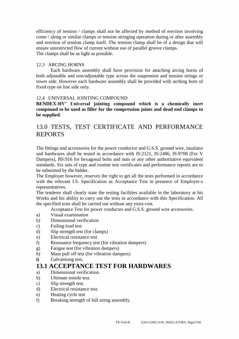
TS-Vol-II E20-COND, E/W, INSULATORS- Page57/82
efficiency of tension / clamps shall not be affected by method of erection involving
come / along or similar clamps or tension stringing operation during or after assembly
and erection of tension clamp itself. The tension clamp shall be of a design that will
ensure unrestricted flow of current without use of parallel groove clamps.
The clamps shall be as light as possible.
12.3 ARCING HORNS
Each hardware assembly shall have provision for attaching arcing horns of
both adjustable and non/adjustable type across the suspension and tension strings or
tower side. However each hardware assembly shall be provided with arching horn of
fixed type on line side only.
12.4 UNIVERSAL JOINTING COMPOUND
BENDEX-HV’ Universal jointing compound which is a chemically inert
compound to be used as filler for the compression joints and dead end clamps to
be supplied.
13.0 TESTS, TEST CERTIFICATE AND PERFORMANCE
REPORTS
The fittings and accessories for the power conductor and G.S.S. ground wire, insulator
and hardwares shall be tested in accordance with IS:2121, IS:2486, IS:9708 (For V
Dampers), BS:916 for hexagonal bolts and nuts or any other authoritative equivalent
standards. Six sets of type and routine test certificates and performance reports are to
be submitted by the bidder.
The Employer however, reserves the right to get all the tests performed in accordance
with the relevant I.S. Specification as Acceptance Test in presence of Employer-s
representatives.
The tenderer shall clearly state the testing facilities available in the laboratory at his
Works and his ability to carry out the tests in accordance with this Specification. All
the specified tests shall be carried out without any extra cost.
Acceptance Test for power conductor and G.S.S. ground wire accessories.
a) Visual examination
b) Dimensional verification
c) Failing load test
d) Slip strength test (for clamps)
e) Electrical resistance test
f) Resonance frequency test (for vibration dampers)
g) Fatigue test (for vibration dampers)
h) Mass pull off test (for vibration dampers)
i) Galvanising test.
13.1 ACCEPTANCE TEST FOR HARDWARES a) Dimensional verification.
b) Ultimate tensile test.
c) Slip strength test.
d) Electrical resistance test.
e) Heating cycle test
f) Breaking strength of full string assembly.

TS-Vol-II E20-COND, E/W, INSULATORS- Page58/82
g) Galvanising test.
13.2 SPECIFIC TECHNICAL REQUIREMENTS FOR
CONDUCTOR ACCESSORIES AND INSULATOR HARDWARES
Conductor Panther/zebra/Moose GSS ground wire
a) Type
b) Material
c) Strand &
Wire diameter.
d) Weight per
Km.
e) Overall
diameter
f) D.C.
Resistance at 20 deg.
C when corrected to
standard weight.
g) Minimum
Breaking
load/Ultimate tensile
strength.
h) Maximum
working tension at
minimum
temperature & 2/3
full wind.
i) Maximum
Sag at maximum
temperature & no
wind.
ACSR Panther/zebra/Moose
Aluminium conductor steel
reinforced.
Panther/Zebra/Moose
Aluminium 30/3mm
Steel 7/3mm,/all.54/3.18mm
steel-7/3.18mm,/ all.54/3.53mm
steel-7/3.53mm
resp.
974/1622 /2004Kg/Km.
21/28.62/31.7 mm
0.13750/0.06915/0.05552
Ohms/KM.
144/13289/16120 Kg
3806/4325 Kg.
6120/9240 mm.
Ground wire.
Galvanised
stranded steel
wire.
7/3.15 mm. and
7/3.66 mm
426 Kg/Km.and
583Kg/Km
9.4mm. and 10.98
mm
3.375 Ohms/KM
5710 Kg.and
10580 Kg
1393 Kg.
5150mm.
DISC Insulator (for suspension & tension Insulator strings) (132 ,220 and 400
KV)
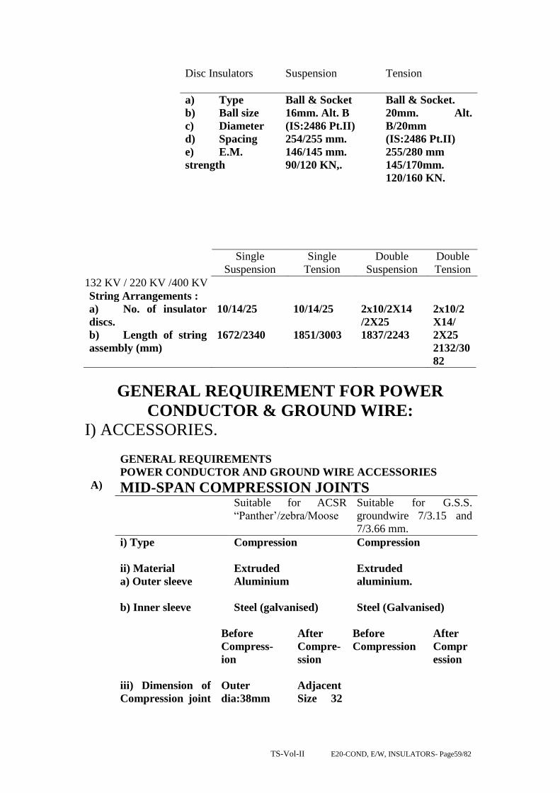
TS-Vol-II E20-COND, E/W, INSULATORS- Page59/82
Disc Insulators Suspension Tension
a) Type
b) Ball size
c) Diameter
d) Spacing
e) E.M.
strength
Ball & Socket
16mm. Alt. B
(IS:2486 Pt.II)
254/255 mm.
146/145 mm.
90/120 KN,.
Ball & Socket.
20mm. Alt.
B/20mm
(IS:2486 Pt.II)
255/280 mm
145/170mm.
120/160 KN.
Single
Suspension
Single
Tension
Double
Suspension
Double
Tension
132 KV / 220 KV /400 KV
String Arrangements :
a) No. of insulator
discs.
b) Length of string
assembly (mm)
10/14/25
1672/2340
10/14/25
1851/3003
2x10/2X14
/2X25
1837/2243
2x10/2
X14/
2X25
2132/30
82
GENERAL REQUIREMENT FOR POWER
CONDUCTOR & GROUND WIRE:
I) ACCESSORIES.
GENERAL REQUIREMENTS
POWER CONDUCTOR AND GROUND WIRE ACCESSORIES
A) MID-SPAN COMPRESSION JOINTS Suitable for ACSR
“Panther‟/zebra/Moose
Suitable for G.S.S.
groundwire 7/3.15 and
7/3.66 mm.
i) Type
ii) Material
a) Outer sleeve
Compression
Extruded
Aluminium
Compression
Extruded
aluminium.
b) Inner sleeve
Steel (galvanised) Steel (Galvanised)
Before
Compress-
ion
After
Compre-
ssion
Before
Compression
After
Compr
ession
iii) Dimension of
Compression joint
Outer
dia:38mm
Adjacent
Size 32
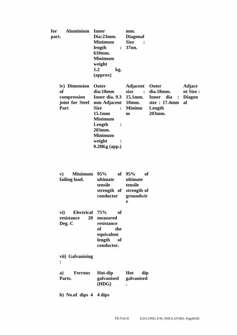
TS-Vol-II E20-COND, E/W, INSULATORS- Page60/82
for Aluminium
part.
Inner
Dia:23mm.
Minimum
length :
610mm.
Minimum
weight
1.2 kg.
(approx)
mm.
Diagonal
Size :
37nn.
iv) Dimension
of
compression
joint for Steel
Part
Outer
dia:18mm
Inner dia. 9.3
mm Adjacent
Size :
15.1mm
Minimum
Length :
203mm.
Minimum
weight :
0.28Kg (app.)
Adjacent
size :
15.1mm.
10mm.
Minimu
m
Outer
dia.18mm.
Inner dia :
size : 17.4mm
Length
203mm.
Adjace
nt Size :
Diagon
al
v) Minimum
failing load.
95% of
ultimate
tensile
strength of
conductor
95% of
ultimate
tensile
strength of
groundwir
e
vi) Electrical
resistance 20
Deg. C
75% of
measured
resistance
of the
equivalent
length of
conductor.
vii) Galvanising
:
a) Ferrous
Parts.
b) No.of dips 4
Hot-dip
galvanised
(HDG)
4 dips
Hot dip
galvanised
.

TS-Vol-II E20-COND, E/W, INSULATORS- Page61/82
dips for 1
minute
withstand.
4 dips
viii)
Minimum
Corona
formation
voltage
110% of maximum
line to ground
voltage
B) VIBRATION DAMPERS:
(SUITABLE FOR ACSR CONDUCTOR: PANTHER/ZEBRA
/MOOSE AND G.S.S. GROUND WIRE 7/3.15 and 7/3.66 mm.
i) Type : 4R Stock Bridge Type
ii) Distance between conductor : 74.5 mm. & axis of the Vibration Damper.
iii) Messenger Cable : 130 Kg/mm sq. quality (19 strands)
iv) Bolt size : 16 mm. (dia.)
v) Slip strength of messenger Cable : 500 Kgs.
vi) Mass pull-of : As per I.S.S.
C) REPAIR SLEEVES: SUITABLE FOR ACSR PANTHER/ZEBRA/MOOSE
CONDUCTOR AND G.S.S. GROUND WIRE.
Suitable for ACSR
panther/Zebra/Moose.
Suitable for G.S.S.
Ground wire.
i) Type Compression Compression.
ii) Material Extruded aluminium. Steel
iii) Min. failing load 95% of UTS of
conductor.
95% of UTS of ground
wire.
iv) Length 241/279 mm. 200 mm (150 mm. min.)
v) Dimension :

TS-Vol-II E20-COND, E/W, INSULATORS- Page62/82
a) After compression
(i) Adjacent side
(b) Before Compression
:
(i)Outerdiameter
38/48mm.
(ii)Innerdiameter
23/40mm
21mm
21mm.
11.5mm.
11.5 mm
vii) Electrical
Resistance at
20 deg. C
Not more than
75% of the resi-
stance of equivalent
length of conductor.
vii) Galvanising :
a) Ferrous parts
Hot – dip galvanized
b) No. of dips for
one-minute stand.
4 dips
D) SUSPENSION CLAMP:
FOR GROUND WIRE 7/3.15 and 7/3.66 mm
i) Type : Envelop type
ii) Material : Forged Steel / NCL.
iii) Minimum slip strength : 25% of UTS of ground wire.
iv) Dimension :
(a) Overall length : 230mm
(b) Inner dia. (before : 10mm.
compression).
(c) Outer diameter : 18mm.
(before compression).
(d) After Compression :
Adjacent : 15.1 mm.
Diagonal side : 17.4mm.

TS-Vol-II E20-COND, E/W, INSULATORS- Page63/82
(e) Galvanising :
(i) Fwerrous parts. : Hot-dip galvanised.
(ii) No. of dips for one- : 4 dips
minute withstand.
E) BONDING PIECES:
a) material : flexible copper bond (37/7/
0.417 mm. tinned copper flexi-
ble stranded cable).
b) Length : Not less than 750 mm.
c) Bolt size : 16mm x 40 mm.
d) Copper area. : 34 sq.mm.
e) Thickness of long : 6 mm.
f) Material for connect - : Tinned Brass
ing socket.
F) INSULATOR HARDWARES
A) String hardwares :
Material and strength
Description of item. Material UTS
i) Bolt hook Forged Steel 11,500 Kgs (90 KN)
ii) Anchor Shackle -do- 15,500 Kgs (120 KN)
iii) Socket Eye Horn - do- 11,500 Kgs (90 KN)
Holder.
iv) Socket Clevis. -do- 15,500 Kgs.
v) Ball Clevis -do- 15,500 Kgs.
vi) Clevis Eye -do- 15,500 Kgs.
vii) Socket Eye. -do- 15,500 Kgs.
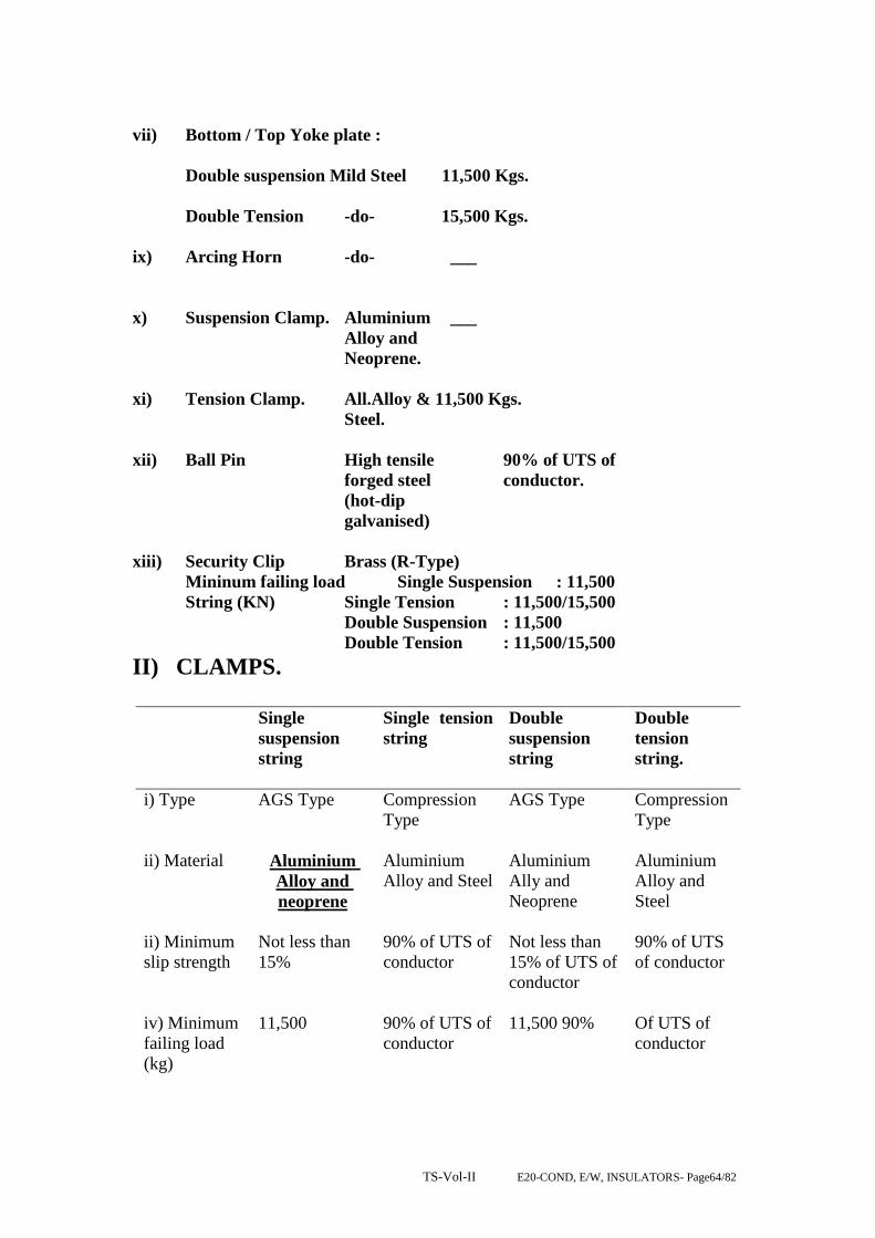
TS-Vol-II E20-COND, E/W, INSULATORS- Page64/82
vii) Bottom / Top Yoke plate :
Double suspension Mild Steel 11,500 Kgs.
Double Tension -do- 15,500 Kgs.
ix) Arcing Horn -do- ___
x) Suspension Clamp. Aluminium ___
Alloy and
Neoprene.
xi) Tension Clamp. All.Alloy & 11,500 Kgs.
Steel.
xii) Ball Pin High tensile 90% of UTS of
forged steel conductor.
(hot-dip
galvanised)
xiii) Security Clip Brass (R-Type)
Mininum failing load Single Suspension : 11,500
String (KN) Single Tension : 11,500/15,500
Double Suspension : 11,500
Double Tension : 11,500/15,500
II) CLAMPS.
Single
suspension
string
Single tension
string
Double
suspension
string
Double
tension
string.
i) Type AGS Type Compression
Type
AGS Type Compression
Type
ii) Material Aluminium
Alloy and
neoprene
Aluminium
Alloy and Steel
Aluminium
Ally and
Neoprene
Aluminium
Alloy and
Steel
ii) Minimum
slip strength
Not less than
15%
90% of UTS of
conductor
Not less than
15% of UTS of
conductor
90% of UTS
of conductor
iv) Minimum
failing load
(kg)
11,500
90% of UTS of
conductor
11,500 90% Of UTS of
conductor

TS-Vol-II E20-COND, E/W, INSULATORS- Page65/82
III). Suspension assembly: armour grip clamp.
1. The armour grip suspension clamp shall comprise of retaining strap,
support housing, elastomer inserts with aluminum reinforcements and
AGS preformed rod set.
2. Elastomer insert shall be resistant to the effects of temperature up to 85
deg. C, ozone, Ultraviolet radiation and other atmospheric contaminants
likely to be encountered in service. The physical properties of the
elastomer shall be of approved standard. It shall be electrically shielded
by a cage of AGS preformed rod set. The elastomer insert shall be so
designed that the curvature of the AGS rod shall follow the contour of the
neoprene insert.
3. The AGS preformed rod set shall be as detailed above in general except
that the length of the AGS preformed rods shall be such that it shall
ensure sufficient slipping strength and shall not introduce unfavourable
stress on the conductor under all operating conditions.
IV) Fasteners: bolts, nuts & washers.
1. All bolts and nuts shall conform to IS-6639 – 1972. All bolts and nuts
shall be galvanized. All bolts and nuts shall have hexagonal heads, the
heads being truly concentric, and square with the shank, which must be
perfectly straight.
2. Bolts upto M16 and having length upto ten times the diameter of the bolt
should be manufactured by cold forging and thread rolling process to
obtain good and reliable mechanical properties and effective dimensional
control. The shear strength of bolt for 5.6 grade should be 310 Mpa
minimum as per IS-12427. Bolts should be provided with washer face in
accordance with IS-1363 Part-I to ensure proper bearing.
3. Fully threaded bolts shall not be used. The length of the bolt shall be such
that the threaded portion shall not extend into the place of contact of the
component parts.
4. All bolts shall be threaded to take the full depth of the nuts and threaded
enough to permit the firm gripping of the component parts but not further.
It shall be ensured that the threaded portion of the bolt protrudes not less
than 3 mm and not more than 8 mm when fully tightened. All nuts shall
fit and be tight to the point where shank of the bolt connects to the head.

TS-Vol-II E20-COND, E/W, INSULATORS- Page66/82
5. Flat washers and spring washers shall be provided wherever necessary
and shall be of positive lock type. Spring washers shall be electro-
galvanized. The thickness of washers shall conform to IS-2016-1967.
6. The bidder shall furnish bolt schedules giving thickness of components
connected, the nut and the washer and the length of shank and the
threaded portion of the bolts and size of holes and any other special
details of this nature.
7. To obviate bending stress in bolt, it shall not connect aggregate thickness
more than three time its diameter.
8. Bolts at the joints shall be so staggered that nuts may be tightened with
spanners without fouling.
9. Fasteners of grade higher than 8.8 are not to be used and minimum grade
for bolts shall be 5.6.
GENERAL:
1. All ferrous parts including fasteners shall be hot dip galvanized, after all
machining has been completed. Nuts may however be tapped (threaded)
after galvanizing and the threads oiled. Spring washers shall be electro-
galvanized. The bolt threads shall be undercut to take care of the increase
in diameter due to galvanizing. Galvanizing shall be done in accordance
with IS-2629-1985 and shall satisfy the tests mentioned in IS 2633-1986.
Fasteners shall withstand four dips while spring washers shall withstand
three dips of one-minute duration in the standard Preece test. Other
galvanized materials shall be guaranteed to withstand at least six
successive dips each lasting one minute under the Standard Preece test for
galvanizing.
2. The zinc coating shall be perfectly adherent of uniform thickness, smooth,
reasonably bright, continuous and free from imperfections such as flux,
ash, rust stains, bulky white deposits and blisters. The zinc used for
galvanizing shall be of grade Zn 99.95 as per IS 209-1979.
3. Pin balls shall be checked with the applicable “G)” gauges in at least two
directions, one of which shall be across the line of die flashing and the
other 90 deg. to this line. „NO GO‟ gauges shall not pass in any direction.
4. Socket ends, before galvanizing shall be of uniform contour. The bearing
surface of socket ends shall be uniform about the entire circumference
without depressions or high spots. The internal contours of socket ends
shall be concentric with the axis of the fittings as per IS 2486/IEC-120.
The axis of the bearing surfaces of socket ends shall be coaxial with the
axis of the fittings. There shall be no noticeable tilting of the bearing
surfaces with the axis of the fittings.

TS-Vol-II E20-COND, E/W, INSULATORS- Page67/82
5. All current carrying parts shall be so designed end manufactured that
contact resistance is reduced to minimum.
6. Welding of aluminum shall be by inert gas shielded tungsten are or inert
gas, shielded metal arc process. Welds shall be clean, sound, smooth, and
uniform without overlaps, properly fused and completely sealed. There
shall be no cracks, voids incomplete penetration, incomplete fusion,
under-cutting or inclusions Porosity shall be minimized so that
mechanical properties of the aluminum alloys are not affected. All welds
shall be properly finished as per good engineering practices.
Electrical Design:
The normal duty and heavy duty suspension, light duty, normal duty and
heavy duty tension insulator sets shall all comply with the technical
requirements of schedule C and satisfy the test requirements stated in
Section-7.
Mechanical design:
The mechanical strength of the insulators and insulator fittings shall be as
stated in Schedule-C
The design shall be such that stresses due to expansion and contraction in
any part of the insulator shall not lead to the development of defects.
Insulating material shall not engage directly with hard metal. All fixing
materials shall be of approved quality, shall be applied in an approved manner
and shall not enter into chemical action with the metal parts or cause fracture
by expansion in service. Where cement is used as a fixing medium, cement
thickness shall be as small and even as possible and proper care shall be taken
to correctly centre and locate the individual parts during cementing.
Technical Specification for Design, Supply and Testing of Hard ware
fittings.
Type tests:
The following type tests shall be conducted on hardware fittings.
A. On suspension hardware fittings only.
(a) Magnetic power loss test.
(b) Clamp slip strength Vs torque
(c ) Mechanical strength test.
(d) On one test on elastomer.
B. On Tension hard ware fittings only.
Electrical resistance test for IS 2486 (Part-I) 1971
Dead end assembly.
(a) Heating cycle test for -do-

TS-Vol-II E20-COND, E/W, INSULATORS- Page68/82
dead end assembly.
(b) Slip strength test for IS 2486 (Part-I)
dead end assembly.
(c ) Mechanical strength test.
C. On both suspension and tension hardware fittings.
(a) Visual examination. IS-2486 (Part-I) 1971
(b) Verification of dimension. -do-
(c ) Galvanizing / electroplating test. -do-
(d) Mechanical strength test of each component
(including corona control ring/grading ring and arcing horn)
(e) Mechanical strength test of welded joint.
(f) Mechanical strength test for corona control ring/
grading ring and arcing horn. BS-3288 (Part-I)
(g) Test on locking device for ball and socket coupling. IEC – 3721984
(h) Chemical analysis, hardness tests, grain size,
inclusion rating and magnetic particle inspection for forging/casting.
D. On suspension hardware fittings only.
(a) Clamp slip strength ver as torque test for suspension clamp.
(b) Shore hardness test of elastomer cushion for AG suspension clamp.
(c) Bend test for armour rod set. IS-2121 (Part-I)
(d) Resilience test for armour rod set. -do-
(e) Conductivity test for armour rod set. -do-
E. On tension hardware fittings only
Unit. 37/4.00
mm2
MID SPAN COMPRESSION
JOINTS FOR CONDUCTORS.
Weight of the joint. Kg. 1.27
Slipping strength. KN 129.6
Resistance of the completed joint. Ohms. 0.000027
Materials of the joints specify alloy type 6201

TS-Vol-II E20-COND, E/W, INSULATORS- Page69/82
and its aluminum contents.
Before compression dia of sleeve. mm
(a) Inner diameter. 31+/-0,5
(b) Outer diameter. 48+/-1.0
Dimensions after compression. mm
(a) Corner to corner. 46+/-0.5
(b) Surface to surface. 40+/-0.5
Length of the sleeve. mm
(a) Before compression. 500+/-5.0
(b) After compression. 540+/-5.0
Compression pressure. Tone 100
Whether designed for intermittent or
continuous compression.
Continuo
us
compressi
on.
Minimum corona extinction voltage
under dry condition.
Kv 154
Radio interference voltage under
conditions.
Micro
volt.
Below
1000
REPAIR SLEEVE FOR
CONDUCTOR
Weight of the sleeve. Kgs. 0.63
Before compression dia of sleeve.
(a) Inner diameter. mm 31.05
(b) Outer diameter. mm 48.10
Dimensions after compression.
(a) Corner to corner. mm 48.05
(b) Surface to surface. mm 40.05
Length of sleeve.
(a) Before compression. mm 279.50
(b) After compression. mm 300.50
Compression pressure. Tone. 100
Minimum corona extinction voltage
under dry condition.
Kv. 154
Radio interference voltage under
condition.
Micro
volt.
Below
1000
(a) Slip strength test for dead end assembly. IS-2121 (Part-I)
All the acceptance tests stated at clause shall also be carried out on composite
insulator unit, except the eccentricity test at clause. In addition to these, all the
acceptance tests indicated in IEC 1109 shall also be carried out without any
extra cost to the employer.
F. For hardware fittings.
(a) Visual examination. IS-2121 (Part-I)

TS-Vol-II E20-COND, E/W, INSULATORS- Page70/82
(b) Proof & test.
G. Tests on conductor accessories.
H. Type tests.
I. Mid span compression joint for conductor and earthwire.
(a) Chemical analysis of materials.
(b) Electrical resistance tests. IS-2121 (Part-II) 1981
clause 6.5 & 6.6
(c) Heating cycle test. -do-
(d) Slip strength test. -do-
(e) Corona extinction voltage test (dry)
(f) Radio interference voltage test (dry)
J. Repair sleeve for conductor.
(a) Chemical analysis of materials.
VIBRATION DAMPER FOR CONDUCTOR.
Vibration Damper for AAC 37/4.00
mm
Unit.
Total weight of the damper. Kgs. 4.5
Weight of each damper mass.
Resonance frequencies.
1. First frequency.
2. Second frequency.
Kgs.
Hz
Hz
Left. Right.
1.6 2.2
12+/- 1 18+/- 2
28+/- 2 36+/- 2
Dimension of each damper mass.
Material of:
1. Damper miss.
2. Messenger cable.
Mm 55 Ox165 60 Ox195
Cast iron hot dip galvanized.
High tensile galvanized steel
wire.
No. of strands in messenger cable
strands.
19
Lay ratio of messenger cable strands. 9-11
Min tensile strength of messenger
cable.
Kg./
Sq.mm
135
Miss pull-off strength. KN 5
Clamping forque. Kg.m 7
Slipping strength of the damper clamp.
1. Before fatigue test.
2. After fatigue test.
KN
2.5
2.0
Magnetic power loss per vibration
damper.
Watts. 1 watt at 500 amps.

TS-Vol-II E20-COND, E/W, INSULATORS- Page71/82
Min. corona extinction voltage under
dry conditions.
Kv. 154
Radio interference voltage under dry
condition 1MHz, at 154 KV.
Microv
olt.
Below 1000
Percentage variation in reactance after
fatigue test in compassion with that
before the fatigue test.
%
20
TS-Vol-II E20-COND, E/W, INSULATORS- Page72/82
SECTION – V
CLAMPS AND CONNECTORS
S.NO. DESCRIPTION PAGE NO.
(A)TECHNICAL SPECIFICATION FOR CLAMPS & CONNECTORS
1. SCOPE 75
2 STANDARDS 75
3. MATERIAL AND WORKMANSHIP 75
4. RATING 76
5. EQUIPMENT CONNECTORS 76
6. TEMPRATURE RISE 77
7. WEIGHTS 77
8. INTERCHANGE ABILITY 77
(B)TECHNICAL SPECIFICATION FOR ACSR BUS-BAR
1. SCOPE 77
2. MATERIALS 77
3. MECHANICAL CHARACTERISTICS 77
4. DIMENSIONAL TOLERANCE 78
5. CHEMICAL COMPOSITION 78
6. ELECTRICAL & MECHANICAL CHARACTERISTICS 78
AND CURRENT RATINGS

TS-Vol-II E20-COND, E/W, INSULATORS- Page73/82
TECHNICAL SPECIFICATION
CLAMPS AND CONNECTORS
(A) TECHNICAL SPECIFICATION FOR CLAMPS & CONNECTORS
1. SCOPE
This specification covers design, manufacture, assembly, testing at
manufacturer‟s works, supply and delivery at site of all terminal connectors of
220,132 & 33KV equipments (mainly breaker, isolator, CT,PT,CVT,BPI and
LA) and all other clamps and dropper connectors required for the switch yard
as per approved lay out and system design.
2. STANDARDS
The terminal connectors under this specification shall conform strictly to the
requirements of the latest version of the following standards as amended up-
to-date, except where specified otherwise.
i) IS: 5561 Power Connectors.
ii) IS:617 Aluminium & Aluminium Alloy
iii) IS: 2629 Recommended Practice for hot dip
galvanizing of iron and steel.
iv) IS: 2633 Method of testing uniformity of coating
of zinc coated articles.
The materials conforming to any other authoritative standards which ensure
equal or better performance shall also be acceptable. The salient point of these
specifications and points of difference between these and the above
specifications, shall be clearly brought out in the bid.
3. MATERIAL & WORKMANSHIP
The terminal connectors shall be manufactured from Aluminium Silicon
Alloy and conform to designation A6 of IS: 617 (latest edition)
The connectors shall be of best quality and workmanship, well finished
and of approved design. Specific materials for clamps and connectors should
have high current carrying capacity, high corrosion resistance and be free from
corona formation.
All connectors or its components to be connected with ACSR conductor
shall be of compression type having aluminium purity not less than 99.5%.

TS-Vol-II E20-COND, E/W, INSULATORS- Page74/82
All bus bar clamps shall be made preferably from forged aluminium of
purity not less than 99.5%. The thickness and contact surface should be
maintained in such a way that the clamp should conform to IS:5561/1970 or
any latest revision thereof.
4. RATING
The connector rating shall match with the rating of the respective equipments
for the terminal connectors and the connectors for bus bar and dropper should
be of the following rating. Minimum thickness at any part of connector shall
be 10(ten)mm. Indicative ratings are given below:
Rating 400/220 / 132 KV
1. Main bus bar connectors high level and 3600/2000/2000
low level (Amps)
2. High level bus sectionalisation 3600/2000/2000
isolator(Amps)
3. Connectors along the bay (Amps) 3600/2000/2000
4. Terminal connectors for CB(Amp.) as per rating of CB
5. -do- for Isolator(Amps) as per rating of ISO
6. -do- for CT As per CT rating
7. -do- for PI As per PI rating
8. -do- for LA As per LA rating
9. -do- for PT As per PT rating
10. -do- for CVT As per CVT rating
11. -do- for WT As per WT rating.
5. EQUIPMENT CONNECTORS
Bimetallic connectors shall be used to connect conductors of dissimilar metal.
The following bimetallic arrangement shall be preferred.
i) copper clodding of minimum 4 mm. thickness on the aluminium
portion of connector coming in contact with the copper palm or stud of
the equipment.
ii) alternatively, to provide
cold rolled aluminium copper strip between the aluminium portion of the connection,
the sheet thickness shall not be less than 2 mm.
Sufficient contact pressure should be maintained at the joint by the provision
of the required number of bolts or other fixing arrangements, but the contact
pressure should not be so great as to clause relaxation of the joint by cold
flow, the joint should be such that the pressure is maintained within this range
under all conditions of service, to avoid excessive local pressure, the contact
pressure should be evenly distributed by use of pressure plates, washers or
suitable saddles of adequate area of thickness should be less than that of an
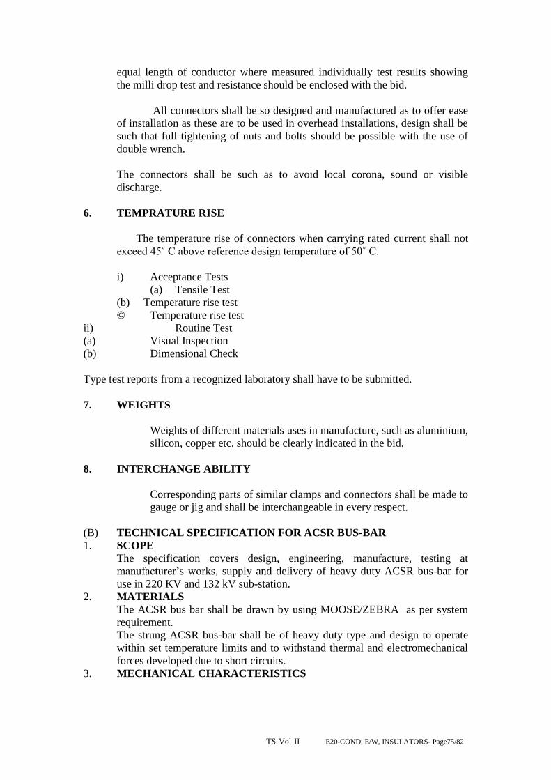
TS-Vol-II E20-COND, E/W, INSULATORS- Page75/82
equal length of conductor where measured individually test results showing
the milli drop test and resistance should be enclosed with the bid.
All connectors shall be so designed and manufactured as to offer ease
of installation as these are to be used in overhead installations, design shall be
such that full tightening of nuts and bolts should be possible with the use of
double wrench.
The connectors shall be such as to avoid local corona, sound or visible
discharge.
6. TEMPRATURE RISE
The temperature rise of connectors when carrying rated current shall not
exceed 45˚ C above reference design temperature of 50˚ C.
i) Acceptance Tests
(a) Tensile Test
(b) Temperature rise test
© Temperature rise test
ii) Routine Test
(a) Visual Inspection
(b) Dimensional Check
Type test reports from a recognized laboratory shall have to be submitted.
7. WEIGHTS
Weights of different materials uses in manufacture, such as aluminium,
silicon, copper etc. should be clearly indicated in the bid.
8. INTERCHANGE ABILITY
Corresponding parts of similar clamps and connectors shall be made to
gauge or jig and shall be interchangeable in every respect.
(B) TECHNICAL SPECIFICATION FOR ACSR BUS-BAR
1. SCOPE
The specification covers design, engineering, manufacture, testing at
manufacturer‟s works, supply and delivery of heavy duty ACSR bus-bar for
use in 220 KV and 132 kV sub-station.
2. MATERIALS
The ACSR bus bar shall be drawn by using MOOSE/ZEBRA as per system
requirement.
The strung ACSR bus-bar shall be of heavy duty type and design to operate
within set temperature limits and to withstand thermal and electromechanical
forces developed due to short circuits.
3. MECHANICAL CHARACTERISTICS

TS-Vol-II E20-COND, E/W, INSULATORS- Page76/82
The mechanical strength of the strung ACSR bus-bar shall be limited to be
maximum allowable tension for specific size of conductor as per ISS.
4. DIMENSIONAL TOLERANCE
Dimensional tolerances shall be as per relevant ISS.
5. CHEMICAL COMPOSITION
The chemical composition for ACSR conductors (MOOSE/ZEBRA) shall be
holding good under all operating condition.
6. ELECTRICAL & MECHANICAL CHARACTERISTICS AND
CURRENT RATINGS
Electrical and mechanical characteristics and current ratings for ACSR bus-bar
shall be same as stipulated for MOOSE/ZEBRA ACSR conductors, the details
of which has been specified.
SCHEDULE OF GUARANTEED TECHNICAL PARTICULARS
LINE HARDWARE AND ACCESSORIES FOR 132/220 KV & GROUND WIRE 7/3.15mm
A HARDWARES Suspension Tension
i Maker’s name and Address ERI-TECH LIMITED
ii Size and designation of ball and
socket with standard specification to
which conforming
16mmB as per IS 2486 20mm as per IS
2486
iii Material
a Anchor shackle NA Forged steel
Galvanised
b Chain Link NA Forged Steel
galvanised
c Ball hook / Ball Link (HH) Forged Steel galvanized Forged Steel
galvanised
d Socket Eye (HH) Forged Steel galvanized NA
e Ball Clevis Forged Steel galvanized Forged Steel
galvanised
f Socket Clevis Forged Steel galvanized Forged Steel
galvanised
g Yoke Plate Mild Steel Galvanised Mild Steel Galvanised
h Arcing Horn Mild Steel Galvanised Mild Steel Galvanised
i Clamp Suspension A.G.S. Clamp NA
j Dead End/Cross arm strap NA NA
k Dead end clamp(Compression) NA Ext. Al. Alloy
iv Standard specification to which the
Hardwares conform IS 2486, IS: 2004,IS:617, IS-2633, & IS-733
v Standard specification to which
conforming IS: 2486
vi Galvanising

TS-Vol-II E20-COND, E/W, INSULATORS- Page77/82
a Ferrous parts Hot Dip Galvanised
b Spring washers Electro Galvanised
c Quality of zinc used 99.5%
d Number of dips which the clamp can
withstand
4/ 1 minute dips
vii Standard to which conforming IS 2633
viii Reference to drawing No. Drg. Attached
ix Minimum failing load in kg For AAAC
& ACSR
Panther (132
kv)
For AAAC &
ACSR Zebra
(220 kv)
For AAAC &
ACSR Moose
(220 kv/400 KV)
a For Single Tension Hardwire
Fittings
120 kN 160 kN 160 kN
b For Double Tension Hardwire
Fittings
120 kN 160 kN 160 kN
c For Single Suspension Hardwire
Fittings
70 kN 70 kN 90/120 kN
d For Double Suspension Hardwire
Fittings
70 kN 70 kN 120 kN
B. TENSION
CLAMPS
Suitable for Panther, Zebra & Moose
(AAAC/ACSR)
i Type Compression type tension clamp
ii Material Ext. Al. Alloy/ Ext. Al.
iii Breaking Strength 95% of UTS of Conductor
iv Slipping strength 95% of UTS of Conductor
v Galvanising
a Ferrous parts Hot Dip Galvanised
b Spring washers Electro Galvanised
c Quality of zinc used 99.5%
d Number of dips which the clamp can
withstand
4/ 1 minute dips
vi Standard to which conforming IS 2633
vii Electrical Conductivity
a. Results of heating cycle test
carried out T.C. Attached
b. Electrical resistance Not more than 75% of equivalent length of
conductor
viii Reference to type tests and other
tests reports attached T.C. Attached
ix Make of bolts and nuts used Local Make
C SUSPENSION
CLAMPS
Panther
(AAAC/AC
SR)
Zebra
(AAAC/ACSR)
Moose
(AAAC/ACSR
)
i Type AGS Type
ii Type of material used for retaining
rod for AGS assembly giving
reference of ISS
Aluminium
Alloy 6061/
Equivalent
Aluminium Alloy
6061/ Equivalent
Aluminium
Alloy 6061/
Equivalent
iii minimum tensile strength of 35 kg/mm2 35 kg/mm2 35 kg/mm2
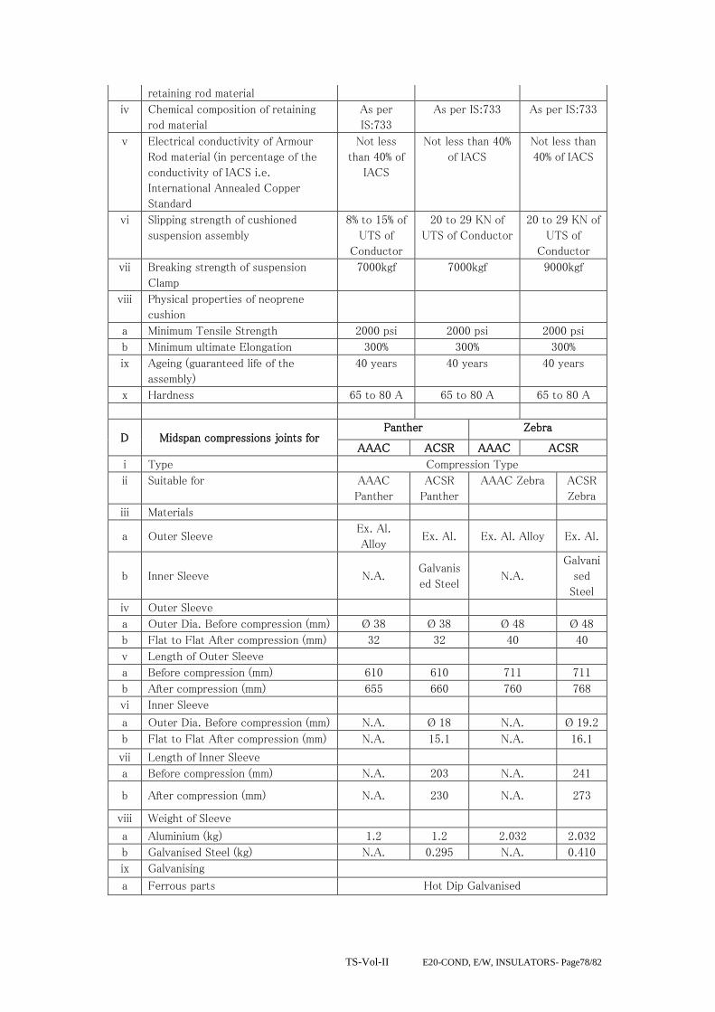
TS-Vol-II E20-COND, E/W, INSULATORS- Page78/82
retaining rod material
iv Chemical composition of retaining
rod material
As per
IS:733
As per IS:733 As per IS:733
v Electrical conductivity of Armour
Rod material (in percentage of the
conductivity of IACS i.e.
International Annealed Copper
Standard
Not less
than 40% of
IACS
Not less than 40%
of IACS
Not less than
40% of IACS
vi Slipping strength of cushioned
suspension assembly
8% to 15% of
UTS of
Conductor
20 to 29 KN of
UTS of Conductor
20 to 29 KN of
UTS of
Conductor
vii Breaking strength of suspension
Clamp
7000kgf 7000kgf 9000kgf
viii Physical properties of neoprene
cushion
a Minimum Tensile Strength 2000 psi 2000 psi 2000 psi
b Minimum ultimate Elongation 300% 300% 300%
ix Ageing (guaranteed life of the
assembly)
40 years 40 years 40 years
x Hardness 65 to 80 A 65 to 80 A 65 to 80 A
D Midspan compressions joints for Panther Zebra
AAAC ACSR AAAC ACSR
i Type Compression Type
ii Suitable for AAAC
Panther
ACSR
Panther
AAAC Zebra ACSR
Zebra
iii Materials
a Outer Sleeve Ex. Al.
Alloy Ex. Al. Ex. Al. Alloy Ex. Al.
b Inner Sleeve N.A. Galvanis
ed Steel N.A.
Galvani
sed
Steel
iv Outer Sleeve
a Outer Dia. Before compression (mm) Ø 38 Ø 38 Ø 48 Ø 48
b Flat to Flat After compression (mm) 32 32 40 40
v Length of Outer Sleeve
a Before compression (mm) 610 610 711 711
b After compression (mm) 655 660 760 768
vi Inner Sleeve
a Outer Dia. Before compression (mm) N.A. Ø 18 N.A. Ø 19.2
b Flat to Flat After compression (mm) N.A. 15.1 N.A. 16.1
vii Length of Inner Sleeve
a Before compression (mm) N.A. 203 N.A. 241
b After compression (mm) N.A. 230 N.A. 273
viii Weight of Sleeve
a Aluminium (kg) 1.2 1.2 2.032 2.032
b Galvanised Steel (kg) N.A. 0.295 N.A. 0.410
ix Galvanising
a Ferrous parts Hot Dip Galvanised

TS-Vol-II E20-COND, E/W, INSULATORS- Page79/82
b Spring washers Electro Galvanized
c Quality of zinc used 99.5%
d Number of dips which the clamp can
withstand
4/ 1 minute dips
x Standard to which conforming IS 2633
xi
Slipping strength of mid span joint
expressed as percentage of UTS of
conductor
95%
xii
Breaking strength of mid span joint
expressed as percentage of UTS of
conduct
95%
xiii
Conductivity of Compression joint
expressed as percentage of
conductivity of cable
100% of equivalent length of conductor
xiv
Resistance as percentage of
measured resistance of equivalent
length of conductor Not more than 75% of equivalent length of
conductor
E Repair Sleeve AAAC & ACSR
Panther
AAAC & ACSR
Zebra
i Type Compression type
ii Suitable for AAAC
Panther
ACSR
Panther
AAA
C
Zebr
a
ACSR Zebra
iii Outside diameter or length of sleeve
a Before compression (mm) Ø 38 Ø 38 Ø 48 Ø 48
b After compression Flat to Flat (mm) 32 32 40 40
iv Length of Sleeve
a Before compression (mm) 241 241 279 279
b After compression (mm) 270 270 310 310
v Material Ex.
Al.Alloy
Ex. Al. Ex.
Al.Al
loy
Ex. Al.
vi Weight of sleeve in (kg) 0.450 0.453 0.81
0
0.810
vii Breaking strength as percentage of
UTS of conductor 95%
viii Conductivity as percentage of
conductivity of conductor 100% of equivalent length of conductor
ix Resistance as percentage of
measured resistance of equivalent
length of conductor
Not more than 75% of equivalent length of
conductors
F Vibration Damper For AAAC & ACSR ZEBRA
i Total weight of the damper (Kg) 4.5 Approx
Left Right
ii Weigh of each damper mass (kgs.) 1.6 2.2
iii Resonance frequencies
1. First frequency (Hz) 12+ 1 18+ 2
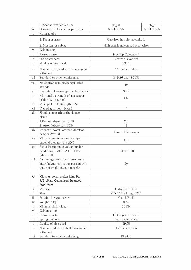
TS-Vol-II E20-COND, E/W, INSULATORS- Page80/82
2. Second frequency (Hz) 28+ 2 36+2
iv Dimensions of each damper mass 60 Φ x 195 55 Φ x 165
v Material of :
1. Damper mass Cast iron hot dip galvanised.
2. Messenger cable. High tensile galvanised steel wire.
vi Galvanising
a Ferrous parts Hot Dip Galvanised
b Spring washers Electro Galvanised
c Quality of zinc used 99.5%
d Number of dips which the clamp can
withstand
4/ 1 minute dips
vii Standard to which conforming IS 2486 and IS 2633
viii No of strands in messenger cable
strands 19
ix Lay ratio of messenger cable strands 9 11
x Min tensile strength of messenger
cable ( kg /sq. mm) 135
xi Mass pull – off strength (KN) 5
xii Clamping torque (Kg.m) 7
xiii Slipping strength of the damper
clamp
1.Before fatigue test (KN) 2.5
2. After fatigue test (KN) 2
xiv Magnetic power loss per vibration
damper (Watts) 1 watt at 500 amps
xv Min. corona extinction voltage
under dry conditions (KV) 154
xvi Radio interference voltage under
conditions 1 MHZ, AT 154 KV
(Microvolt)
Below 1000
xvii Percentage variation in reactance
after fatigue test in comparison with
that before the fatigue test (%)
20
G Midspan compression joint For
7/3.15mm Galvanised Stranded
Steel Wire
i Material Galvanized Steel
ii Size OD 20.2 x Length 230
iii Suitable for groundwire Yes (7/3.15)
iv Weight in kg 0.85
v Minimum failing load 50 KN
vi Galvanization
a Ferrous parts Hot Dip Galvanised
b Spring washers Electro Galvanised
c Quality of zinc used 99.5%
d Number of dips which the clamp can
withstand
4 / 1 minute dip
vii Standard to which conforming IS 2633

TS-Vol-II E20-COND, E/W, INSULATORS- Page81/82
H Suspension Clamps For 7/3.15mm
Galvanised Stranded Steel Wire
i Materials Malleable Cast Iron / Galvansied Steel
ii Size As per Drawing
iii Suitable for groundwire Yes (7/3.15)
iv Weight in kg
v Slip strength 12-17 KN
vi Minimum failing load 70 KN
vii Galvanising
a Ferrous parts Hot Dip Galvanised
b Spring washers Electro Galvanised
c Quality of Zinc used 99.5%
d Number of dips which the clamp can
withstand
4/1 minute dips
viii Standard to which conforming IS 2486 and IS 2633
I Compression type dead end
assemblies For 7/3.15mm
Galvanised Stranded Steel Wire
i Materials Forged steel
ii Size As per drawing
iii Suitable for ground wire Yes (7/3.15)
iv Weight in kg 3.69
v Minimum failing load 70 KN
vi Galvanising
a Ferrous parts Hot Dip Galvanised
b Spring washers Electro Galvanized
c Quality of zinc used 99.5%
d Number of dips which the clamp can
withstand
4/ 1 minute dips
vii Standard to which conforming IS 2486 and IS 2633
J Flexible copper
bond
i Drawings enclosed Yes
ii Stranding 37/7/0.417
iii Cross sectional area (Sq.mm) 75.6
iv Minimum copper equivalent area
(Sq.mm)
34 (each individual wire)
vi Length of copper cable (mm) 500
vii Material lugs Tinned Copper
viii Bolt Size
(i) Diameter (mm) 16
(ii) Length (mm) 40
ix Resistance (Ohm) 0.0004 ( as per IS:2121)
x Total weight of flexible copper bond
(kg)
0.45 (approx)

TS-Vol-II E20-COND, E/W, INSULATORS- Page82/82

VOL-II (TS) E26-TRANSMISSION LINE- Page 1 of 105
ODISHA POWER TRANSMISSION CORPORATION LIMITED
TECHNICAL SPECIFICATION
FOR
CONSTRUCTION OF
1)132 KV SC/DC,
2)220 KV SC/DC AND
3)400 KV DC

VOL-II (TS) E26-TRANSMISSION LINE- Page 2 of 105
TRANSMISSION LINES
Nature of work The work covered by this Specification is for 400 kV and/or 220 kV and/or 132 kV
transmission lines as specified herein and in the attached Schedules. The overhead
transmission lines will form part of the OPTCL Transmission System.
General particulars of the system The following are the general particulars governing the design and working of the
complete system of which the Works will form a part —
a) Electrical energy is generated at interconnected power stations as three-phase
current at a frequency of 50 Hz, and transmitted therefrom by means of overhead
lines.
b) The system will be in continuous operation during the varying atmospheric and
climatic conditions occurring at all seasons
1.0 SCOPE-
Construction of 400 KV, 220 KV and 132 KV
As indicated in the Bidding Proposal Sheet & scope of work.
Important: Contractor has to obtain project license from the competent authority
in respect of the mentioned works prior to commencement of the
works. The expenses towards the project license have to be borne by
the contractor.
2.0 SURVEY (detail & check, estimating of quantities & spotting of towers)
2.1.1 General: Preliminary route alignment in respect of the proposed transmission
lines has been fixed by the employer subject to alteration of places due to way
leave or other unavoidable constraints. The Right of way shall be solved by the
contractor and all expenses there of shall be borne by him. However, OPTCL
shall render all helps in co-ordination with law and order department for solving
the same. Forest clearance if any shall be arranged by OPTCL.
2.1.2 Provisional quantities/numbers of different types of towers have been estimated
and indicated in the BOQ Schedule given. However final quantities for work shall be as
determined by the successful bidder, on completion of the detail survey, preparation of
route profile drawing and designing of the different types of towers as elaborated sin
the specification and scope of work.
2.1.2.1 The contractor shall undertake detailed survey on the basis of the tentative
alignment fixed by the employer. The said preliminary alignment may, however,
VOL-II (TS) E26-TRANSMISSION LINE- Page 3 of 105
change in the interest of economy to avoid forest and hazards in work. While surveying
the alternative route the following points shall be taken care by the contractor.
(a) The line is as near as possible to the available roads in the area.
(b) The route is straight and short as far as possible.
© Good farming areas, religious places, forest, civil and defence
installations, aerodromes, public and private premises, ponds, tanks,
lakes, gardens, and plantations are avoided as far as practicable.
(d) The line is far away from telecommunication lines as reasonably
possible. Parallelism with these lines shall be avoided as far as
practicable.
(e) Crossing with permanent objects are minimum but where unavoidable
preferably at right angles.
(f) Difficult and unsafe approaches are avoided.
(g) The survey shall be conducted along the approved alignment only in
accordance with IS: 5613 (Part-II/Section-2), 1985.
(h) For river crossing/ Crossing of Nallas : Taking levels at 25 metre
interval on bank of river and at 50 metre interval at bed of river so far as
to show the true profile of the ground and river bed. The levels may be
taken with respect to the nearest existing towers, pile foundation of
towers, base or railway/road bridge, road culvert etc. The levels shall be
taken at least 100 m. on either side of the crossing alignment. Both
longitudinal and cross sectional shall be drawn preferably to a scale of
1:2000 at horizontal and 1:200 vertical.
After completing the detailed survey, the contractor shall submit the final profile and
tower schedule for final approval of the employer. The final profile and tower
schedule shall incorporate position of all type of towers. To facilitate checking
of the alignment, suitable reference marks shall be provided. For this purpose,
concrete pillars of suitable sizes shall be planted at all angle locations and
suitable wooden/iron pegs shall be driven firmly at the intermediate points. The
contractor shall quote his rate covering these involved jobs.
Only approved sag template shall be used for tower spotting and the final
profiles.
However preliminary survey has been done by OPTCL and any further survey
required shall be done by the contractor.
2.1.2.2 PROFILE PLOTTING AND TOWER SPOTTING
The profile shall be plotted and prepared to the scale 1 in 2,000 for horizontal and 1 in
200 for vertical on squared (mm) paper. If somewhere the difference in levels
VOL-II (TS) E26-TRANSMISSION LINE- Page 4 of 105
be too high, the chart may be broken up according to the requirements. A 10
mm overlap shall be shown on each following sheet. The chart shall progress
from left to right for convenience in handling. The sheet size may be
conveniently chosen.
With the help of sag template, final tower location shall be marked on the
profiles and while locating the tower on survey chart, the following shall be
kept in mind:
(a) The number of consecutive span between the section points shall not exceed 10
in case of straight run on a more or less plain stretch.
(b) Individual span shall be as near as to the normal design ruling span.
In different crossing the contractor shall take into consideration the
prevailing regulations of the respective authorities before finalizing
type and location of the towers. While carrying out survey work, the
contractor has to collect all relevant data, prepare and submit
drawings in requisite number for obtaining clearance from the
PTCC, road, aviation, railways, river and forest authorities.
The contractor shall remain fully responsible for the exact alignment of the line. If after
erection, any tower is found to be out of alignment, the same shall have to be
dismantled and re-erected after corrosion by the contractor at his own cost, risk
and responsibility, including installation of fresh foundation, if belt necessary
by the employer.
After peg marking of the angle tower or tension towers, the contractor shall obtain
approval from the employer and thereafter pegging of suspension type tower
shall be done by the contractor and pegging of all the four legs of each type of
towers at all the locations shall be done.
2.1.2.3 SCHEDULE OF MATERIALS
When the survey is approved, the contractor shall submit to the employer a complete
detail schedule of all materials to be used in the line. Size and length of
conductor etc. are also to be given in the list. This schedule is very essential for
finalizing the quantities of all line material. The contractor shall furnish the
same.
2.1.2.4 CHECK SURVEY
The contractor shall undertake the check survey during execution on the basis of the
alignment profile drawing and tower schedule approved by the employer. If
during check survey necessity arises for minor change in route to eliminate way
leave or other unavoidable constraints, the contractor may change the said
alignment after obtaining prior approval from the employer.

VOL-II (TS) E26-TRANSMISSION LINE- Page 5 of 105
The contractor, while carrying out the check survey, shall peg mark the power position
on ground conforming to the survey charts. In the process, it is necessary to
have the pit centers marks according to the excavating marking charts to be
prepared by the contractor and approved by the employer. The levels up or
down of each pit center with respect to the center of the tower location shall be
noted and recorded for determining the amount of earth work required to meet
the design. At the charting point of the route survey, an angle iron spite shall be
driven firmly into the ground showing a little above the ground level.
2.1.2.5 WAY-LEAVE AND TREE CUTTING
Way-leave permission which may be required by the contractor shall be arranged at his
cost. While submitting final-survey report for approval, proposals for way-leave
right of way shall be submitted by the contractor. Employer may extend help to
get the permission within a reasonable time as mutually agreed upon for which
due notice shall be given by the contractor in such a way so that obtaining
permission from appropriate authority do not hinder the continued and smooth
progress of the work.
The employer shall not be held responsible for any claim on account of damage done
by the contractor or his personnel to trees, crops and other properties.
The contractor shall take necessary precaution to avoid damage to any ripe and partially
grown crops and in the case of unavoidable damage, the employer shall be
informed and necessary compensation shall be paid by the contractor.
All the documents required for application to the statutory authorities must be prepared
by the contractor & submission to the employer for Submission of the
application towards approval of PTCC, Railway Crossing etc. However, the
responsibilities lies with the contractor to get the clearance.
Trimming of tree branches or cutting of a few trees en-route during survey is within the
scope of survey to be done by the contractor. Contractor shall arrange for
necessary way-leave and compensation in this regard. During erection of the
line, compensation for tree cutting, damage caused to crops, actual cutting and
felling of the trees including way-leave permission for such route clearance
shall be arranged by the contractor at his cost. The contractor will identify the
number of trees and detail of obstructions to be removed for erection of the line
and intimate the employer well in advance in case of any help. Other related
works like construction of temporary approach roads, etc. as required, shall be
done by the contractor and the same will lie within the scope of contractor’s
work and such cost shall be considered to be included in the rates quoted by
him.
While quoting the rate for detailed and check survey as per bidding activity schedule,
the contractor shall include all costs involved in different activities described
herein earlier.
2.0 SUB-SOIL INVESTIGATION

VOL-II (TS) E26-TRANSMISSION LINE- Page 6 of 105
To ascertain soil parameters in various stretch inter, the contractor shall carry out sub-
soil investigation through reputed soil consultant as approved by the employer.
2.1 SCOPE OF WORK
The scope of sub-soil investigation covers execution of complete soil exploration for
the transmission line under this contract including boring, drilling, collection of
undisturbed soil sample where possible, otherwise disturbed samples,
conducting laboratory test of soil samples to find out the various parameters as
detailed in this specification and submission of detailed reports in 6 copies
along with specific recommendation regarding suitable type of foundation for
each bore-hole along with recommendation for soil improvement where
necessary.
2.1.1 QUALIFYING REQUIREMENTS OF SOIL CONSULTANTS
The soil consultants shall provide satisfactory evidence concerning the following as and
when asked for.
That, he/they has/have adequate technical knowledge and previous practical experience
in carrying out complete soil investigation jobs in any kind of soil.
That he/they has/have well equipped, modernized soil testing laboratory of his/their
own. If asked for by the employer, the contractor shall arrange inspection of
such laboratory of the soil consultant by the representative of the employer.
If in the opinion of the employer, the soil consultant (proposed by the contractor) is not
well equipped or capable to undertake the sub-soil investigation job relating to
this contract, then such soil consultant shall not be engaged to undertake the job.
In that case, they shall have to engage other agency as will be approved by the
employer.
2.1.3 TEST BORING
The boring shall be done at the major locations/crossing, special towers. However, it is
desirable that there should be at least one sub-soil investigation bore-hole for
the line. Such locations for sub-soil investigation shall be selected and finalized
in consultation with the employer.
The test boring through different layers of all kinds of soil shall have to be carried out
by the contractor through the approved soil consultant as briefed hereunder.
(a) Method of boring, selection of sampling tubes, sampling, recording of boring,
protection, handling, leveling of samples shall be done as specified in IS: 1892/1977, if
any, after obtaining approval from the employer. The contractor/consultant shall furnish
in the soil report in details, the equipment and method of boring actually adopted.
(b) Depth of boring below ground level shall be 15 M. only unless continuous
bedrock is encountered earlier. In case rock is encountered at any depth within 15 M.

VOL-II (TS) E26-TRANSMISSION LINE- Page 7 of 105
adequate study of rock and assessment of strength characteristics shall be done and
recommendation shall be given.
(c) Undisturbed soil samples shall be obtained for the initial 4M depths at every
1.5M interval and at change of strata. After these initial 4M depths, samples shall be
obtained preferably at every 3M or where there is a change of strata, or as advised by
the employer.
(d) In case collection of undisturbed samples becomes difficult/impossible detailed
soil testing on remoulded soil samples is to be considered and reported in the soil
report.
(e) Standard penetration test as per IS: 2131 with latest amendment shall have to be
conducted in different strata and recorded properly.
(f) The ground water table shall be recorded during boring operation and
incorporated in the bore log. If possible, the position of the water table just after
monsoon period be ascertained from local people and indicated in the report.
(g) Plate Load test shall have to be conducted at special tower location.
3.0 LABORATORY TESTS OF SOIL SAMPLES
The method and procedure of testing of soil sample to be followed shall be as per
relevant IS codes. Adequate volume of test samples shall be collected from site.
Ample shall be properly sealed immediately after recovery as specified in
relevant IS code and transported carefully to laboratory for carrying out
necessary laboratory tests to find out the following parameters of every samples.
Data and time of taking of the sample shall be recorded in the test report.
(a) Natural moisture content, Liquid limit, Plastic limit and Plasticity index.
(b) Bulk, dry and buoyant density of soil.
(c) Void ratio (e-long P curve shall be submitted)
(d) Specific gravity.
(e) Grain size distribution (Sieve analysis and hydrometer analysis)
(f) Tri-axial and consolidation tests (consolidation undrained and consolidated
drained as and when application in table, graph and drawing.
(g) Permeability tests
(h) Chemical tests for both water and soil samples at different layers.
(i) Evaluation of safe bearing capacity at different strata for square footings shall
be done for a maximum value of 25-mm. settlements.
(j) At depts. From 3M to 10M be different strata.
(k) Factor of safety shall be considered as 3 for evaluation of safe bearing capacity
of soil.
(l) Unconfined compression test for cohesive soil (=0) if encountered.
3.1 REPORT ON SUB-SOIL INVESTIGATION

VOL-II (TS) E26-TRANSMISSION LINE- Page 8 of 105
The contractor shall make analysis of soil samples and rock cores as collected by him in
the field and approved by the employer as collected by him in the field and
approved by him in the field and approved by the employer as well as field tests
and laboratory tests. A comprehensive report shall have to be prepared by him,
finally incorporating all the data collected in proper tabular forms or otherwise
along with the analysis.
The 3(three) copies of report in the draft form shall be submitted for employer’s
approval. 6(six) copies of final report incorporation employer’s comments, if
any shall be submitted within 3(three) weeks after completion of this work.
Recommendations shall include but not be limited to the following items (a) to (p)
(a) Geological information of the region.
(b) Past observations and historical data, if available, for the area or for other areas
with similar profile or for similar structures in the nearby area.
(c) Procedure of investigations employed and field and field as well as laboratory
test results.
(d) Net safe bearing capacity and settlement computation for different types of
foundations for various widths and depths of tower and building.
(e) Recommendations regarding stability of slopes, during excavations etc.
(f) Selection of foundation types for towers, transformers and buildings etc.
(g) Bore hole and trial pit logs on standard proforma showing the depths, extent of
various soil strata etc.
(h) A set of longitudinal and transverse profiles connecting various boreholes shall
be presented in order to give a clear picture of the site, how the soil/rock strata are
varying vertically and horizontally.
(i) Modulus of sub grade reaction from plate load test for pressure ranging up to 6
kg/cm. The recommended values shall include the effect of size, shape and depth of
foundations.
(j) Deformation modulus from plate load test in various test depth/stratification.
(k) Coefficient of earth pressure at rest.
(l) Depth of ground water table and its effect on foundation design parameters.
(m) Recommendations regarding stability of slopes, during shallow excavation etc.
(n) Whether piles are necessary or not. If piles are necessary, recommendation of
depth, diameter and types of piles to be used.
(o) Recommendations for the type of cement to be used and any treatment to the
underground concrete structure based on the chemical composition of soil and sub-soil
water.
3.1.2 MEASUREMENT OF SOIL RESISTIVITY
For the purpose of grounding design, soil resistance measurement shall be taken in the
locations as stated under clause 1.0 above and based on which the value of soil
resistance shall be derived.
Wenner’s four (4) electrode method shall be used for earth resistance measurement in
accordance with the procedure and the calculation detailed in IS:3043 1987. At

VOL-II (TS) E26-TRANSMISSION LINE- Page 9 of 105
least 8(eight) test direction shall be chosen from the center of the locations to
cover the whole site.
The employer reserves the right to carry out separate soil investigation at his cost by
engaging a separate agency for cross checking the result obtained by the
contractor.
In case the results are at variance, the soil parameters to be adopted for final design will
be at the sole discretion of the employer and such will be binding upon the
contractor.
IMP:-The material and services covered under these specifications shall be
performed as per requirements of the relevant standards and codes referred
hereinafter against each set of equipment and services. In case of a conflict
between such codes and/or standards and the Specifications, the latter shall
govern. Other Internationally acceptable standards which ensure equal or higher
performance than those specified shall also be accepted.
---------------------------------------------------------------------------------------------------
SL. Indian Title International &
No. Standards Internationally
recognised
Standards.
--------------------------------------------------------------------------------------------------
1. 2. 3. 4.
--------------------------------------------------------------------------------------------------
1. IS 209-1979 Specification for ISO/R/752-1968 Zinc ASTM B6 2. IS 226-1975 Structural steel ISO/R/630-1967 (Standard quality) CAN/CSA G40.21 BSEN 10025 3. IS 269-1976 Ordinary rapid har- ISO/R/597-1967 dening and low heat Portland cement. 4. IS 383-1970 Coarse and fine aggre- CSA A23.1 /A23.2 gates from natural sources for concrete. 5. a) IS 398-1982 Specification for IEC 1089-1991 Part-I aluminium conduc- BS 215-1970 tors for overhead transmission purposes b) IS 398-1982 Aluminium conductor BS 215-1970 Part-II galvanised steel IEC 1089-1991 reinforced c) IS 398-1994 Aluminium alloy BS 3242-1970 Part-IV stranded conductor IEC 1089-1991 ASTM 8393M86
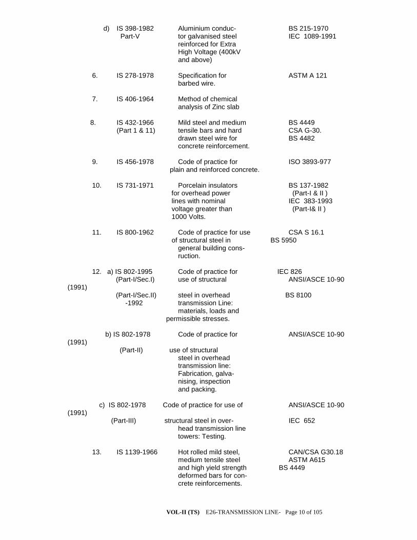
VOL-II (TS) E26-TRANSMISSION LINE- Page 10 of 105
d) IS 398-1982 Aluminium conduc- BS 215-1970 Part-V tor galvanised steel IEC 1089-1991 reinforced for Extra High Voltage (400kV and above) 6. IS 278-1978 Specification for ASTM A 121 barbed wire.
7. IS 406-1964 Method of chemical analysis of Zinc slab 8. IS 432-1966 Mild steel and medium BS 4449 (Part 1 & 11) tensile bars and hard CSA G-30. drawn steel wire for BS 4482 concrete reinforcement. 9. IS 456-1978 Code of practice for ISO 3893-977 plain and reinforced concrete.
10. IS 731-1971 Porcelain insulators BS 137-1982 for overhead power (Part-I & II ) lines with nominal IEC 383-1993 voltage greater than (Part-I& II ) 1000 Volts. 11. IS 800-1962 Code of practice for use CSA S 16.1 of structural steel in BS 5950 general building cons- ruction. 12. a) IS 802-1995 Code of practice for IEC 826 (Part-I/Sec.I) use of structural ANSI/ASCE 10-90 (1991) (Part-I/Sec.II) steel in overhead BS 8100 -1992 transmission Line: materials, loads and permissible stresses. b) IS 802-1978 Code of practice for ANSI/ASCE 10-90 (1991) (Part-II) use of structural steel in overhead transmission line: Fabrication, galva- nising, inspection and packing. c) IS 802-1978 Code of practice for use of ANSI/ASCE 10-90 (1991) (Part-III) structural steel in over- IEC 652 head transmission line towers: Testing. 13. IS 1139-1966 Hot rolled mild steel, CAN/CSA G30.18 medium tensile steel ASTM A615 and high yield strength BS 4449 deformed bars for con- crete reinforcements.
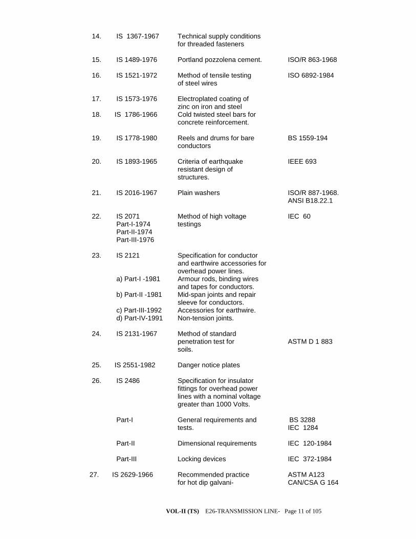
VOL-II (TS) E26-TRANSMISSION LINE- Page 11 of 105
14. IS 1367-1967 Technical supply conditions for threaded fasteners 15. IS 1489-1976 Portland pozzolena cement. ISO/R 863-1968 16. IS 1521-1972 Method of tensile testing ISO 6892-1984 of steel wires 17. IS 1573-1976 Electroplated coating of zinc on iron and steel 18. IS 1786-1966 Cold twisted steel bars for concrete reinforcement. 19. IS 1778-1980 Reels and drums for bare BS 1559-194 conductors 20. IS 1893-1965 Criteria of earthquake IEEE 693 resistant design of structures. 21. IS 2016-1967 Plain washers ISO/R 887-1968. ANSI B18.22.1 22. IS 2071 Method of high voltage IEC 60 Part-I-1974 testings Part-II-1974 Part-III-1976 23. IS 2121 Specification for conductor and earthwire accessories for overhead power lines. a) Part-I -1981 Armour rods, binding wires and tapes for conductors. b) Part-II -1981 Mid-span joints and repair sleeve for conductors. c) Part-III-1992 Accessories for earthwire. d) Part-IV-1991 Non-tension joints. 24. IS 2131-1967 Method of standard penetration test for ASTM D 1 883 soils. 25. IS 2551-1982 Danger notice plates 26. IS 2486 Specification for insulator fittings for overhead power lines with a nominal voltage greater than 1000 Volts. Part-I General requirements and BS 3288 tests. IEC 1284 Part-II Dimensional requirements IEC 120-1984 Part-III Locking devices IEC 372-1984 27. IS 2629-1966 Recommended practice ASTM A123 for hot dip galvani- CAN/CSA G 164

VOL-II (TS) E26-TRANSMISSION LINE- Page 12 of 105
sing of iron and steel. BS 729 28. IS 2633-1972 Method of testing ASTM A123 uniformity of coating CAN/CSA G164 of zinc coated articles. 29. IS 3043-1972 Code of practice for earthing(with amend- ment No.1 and 2). 30. IS 3063-1972 Single coil rectangular DIN 127-1970 section spring washers for bolts nuts, screws. 31. IS 3188-1965 Dimensions for disc IEC 305-1978 insulators. 32. IS 4091-1967 Code of practice for ASCE/IEEE 691 design and construction of foundation for trans- mission line towers and poles. 33. IS 4826-1979 Galvanised coating on IEC 888-1987 round steel wires. BS 443-1982 34. IS 5358-1969 Hot dip galvanised coat- CAN/CSA G 164 ings on fasteners. ASTM A153 35. IS 5613 Code of practice for ANSI/ASCE 10-90(1991) (Part-II/Sec-1) design, installation and -1985 maintenance of overhead (Part-III/Sec.1) power lines (Section-l: -1989 Designs) 36. IS 5613 Code of practice for (Part-II/Sec-2) design, installation and -1985 maintenance of overhead (Part-III/Sec.2) power lines (Section 2: -1989 Installation and maintenance) 37. IS 6610-1972 Specification for heavy washers for steel structures. 38. IS 6639-1972 Hexagonal bolts for steel ISO/R 272-1968 structure. ASTM A394 CSA B33.4 39. IS 6745-1972 Methods for determination ASTM A90 of weight of zinc coating ISO 1460 of zinc coated iron and steel articles. 40. IS 8263-1976 Method of radio interference IEC 437-1973 tests on high voltage insulator NEMA 107-1964 41. IS 8269-1976 Method of switching impulse IEC 506-1975 tests on HV insulators.

VOL-II (TS) E26-TRANSMISSION LINE- Page 13 of 105
42. IS 8500-1977 Specification for weldable BSEN 10025 structural steel (medium and high strength qualities) 43. IS 9708-1980 Specification for Stock Bridge vibration dampers for overhead power lines. 44. IS 9997-1988 Aluminium alloy redraw rods IEC 104-1987 45. Hard drawn aluminium wires for IEC 889-1987 overhead line conductors. 46. Thermal mechanical performance IEC 575-1977 tests and mechanical performance tests on string insulator units. 47. Salt fog pollution voltage IEC 507-1991 withstand tests. 48. Residual strength of string IEC 797-1984 insulator units of glass or ceramic material for overhead lines after mechanical damage of the dielectric. 49. Guide for the selection of insu- IEC 815-1986 lators in respect of polluted conditions. 50. Tests on insulators of ceramic IEC 383-1993 material or glass for overhead (Part I and II ) lines with a nominal voltage greater than 1000 Volts. 51. Ozone test on elastomer ASTM D-1171 52. IS 1363 Hexagonal head bolts, screws and nuts of product Grade - C Part - 1 Hexagonal head bolts ISO 4016 Part - 3 Hexagonal nuts ISO 4034 53. IS 1367 Technical supply conditions for threaded steel fasteners Part III Mechanical properties and test ISO 898-1 methods for bolts, screws and studs with full loadability Part VI Mechanical properties and ISO/DIS 898/II test methods for nuts with full loadability 54. Indian Electricity Rules - 1956

VOL-II (TS) E26-TRANSMISSION LINE- Page 14 of 105
55. Indian Electricity Act - 1910 56. IS 1498-1970 Classification and identification of soil for general engineering purposes 57. IS 1888-1982 Method of load test on soils 58. IS 1892-1979 Code of practice for subsurface investigation for foundation 59. IS 2911-1979 Code of practice for design and (Part-I) construction of pile foundations 60. IS 4453-1980 Code of practice for exploration by pits, trenches, drifts and shafts 61. IS 6935-1973 Method for determination of water level in a bore hole 62. IS 8009-1976 Code of practice for calculation of (Part-I) settlement of foundation subjected to symmetrical vertical loads (Shallow Foundation) 63. IS 2386-1963 Methods of test for aggregates for (Part-3) concrete : Specific gravity, density, voids, absorption and bulking 64. IS 14000-1994 Quality management and quality ISO 9000-1994 assurance standards 65. GRIDCO Safety Manual (draft)-1997 66. Composite insulators for a.c. overhead IEC 1109-1992 lines with a nominal voltage greater than ANSI C29-11 1000 V : Definition, test methods and IEEE 987 acceptance criteria ----

VOL-II (TS) E26-TRANSMISSION LINE- Page 15 of 105
SUPPLY OF TOWER STRUCTURES FOR THE
TRANSMISSION LINES 1.0 SCOPE
1.1 This specification provides for design, proto fabrication, galvanizing and
delivery FOR (destination) of transmission line towers including super-structure stubs,
tower extensions, stub-templates, tower accessories (Hangers, U-bolts, bird guards,
anti-climbing devices), bolts and nuts, step bolts, flat and spring washers etc. as
described hereinafter in this volume.
THE PRELIMINARY SURVEY WORK HAS ALREADY DONE AND THE
FOLLOWING TOWERS HAVE BEEN DECIDED.
The contractor shall design the tower foundation and the concreting shall
be done by M-20 grade concrete.
a) Wind effects:
Tower shall be designed for reliability Level-I, Terrain category-I &
Wind Zone-V Design wind pressure on towers, conductors, earth wire and
insulator string in the range of 30.45 mt. And above 45 mt. Height shall be
computed as per IS-802(Part/Sec-I) 1995 Bidder shall furnish the maximum
wind pressure adopted in their design against each component mentioned above.
b) Design Temperatures:
The following temperature range for the power conductor and ground wires
shall be adopted for the line design:
(i) Minimum temperature: 5 deg. C
(ii) Everyday temperature of conductor: 32 deg. C
(iii) Maximum temperature of :
a) Conductor:ACSR 75 deg. C for ACSR
Moose/Zebra/Panther 90 deg. C for AAAC.
(**Double Moose conductor in 400 KV system)
b) Ground wire exposed to sun. 53 deg. C
The above values are subject to latest revision if any made in IS-802 (part-I/Sec-I) 1995
Maximum Tension:
Maximum tension shall be based on either:
a) at 5 deg. C with 2/3rd
. full wind pressure or Conform to IS 802-1995
b) at 32 deg. C with full wind pressure whichever Part-I/Sec-I-Clause No.10.3
is more stringent.
Factors of Safety & Span details:
Factor of Safety: Should conform to IS-802 Part-I-1995
Normal span: The normal span of the line shall be 350 meters of 220KV and
320 meters for 132 KV.
Wind & Weight Span: The wind and weight span to be adopted in the design of the
structures shall be as follows:
(i) Wind span: The wind span is the sum of the two half spans adjacent to the
support under consideration. In case of towers located on a perfectly horizontal terrain,

VOL-II (TS) E26-TRANSMISSION LINE- Page 16 of 105
this shall be the normal span. For design purpose the wind on conductor shall be
calculated on a wind span of at least 1.1 times the normal span.
Weight Span: The weight span is the horizontal distance between the lowest point of
the conductors on the two spans adjacent to the tower. All C and D type towers shall be
designed for uplift spans (minimum weight spans in the following table) also. These are
applicable both for pointed and square cross arms.
For details of cross arms and towers , the span limits given below shall prevail.
Towe
r
type.
400KV/220 KV 132 KV
Normal
condition.
Broken wire
condition.
Normal condition. Broken wire
condition.
Max. Min. Max. Min. Max. Min. Max. Min.
A/DA
&
B/DA
525 100 315 100 500 100 300 100
C/DC
&
D/DD
600 100 360 100 500 100 300 100
1.1.1 The design of towers and their extensions shall be done conforming to the
design parameters specified herein, the scope of design also includes supply of design
calculation for towers and extensions including detailed structural/shop drawings of
towers extensions and stub setting templates. The bidder, who has already type tested
the various tower viz: 0-2˚, +3, +6; 0-15˚, +3, +6; 0-30˚, +3, +6; 0-60˚, +3, +6 (
400/220/132 KV) in any nationally or internationally recognized laboratories, and
conforming to our specification, may also offer the same.
1.1.2 STANDARDS
Except as modified in this specification, the material and work covered under this
specification, shall conform to the latest revision with amendments thereof of the
following of Indian Standards and equivalent International Standards whenever
indicated below.
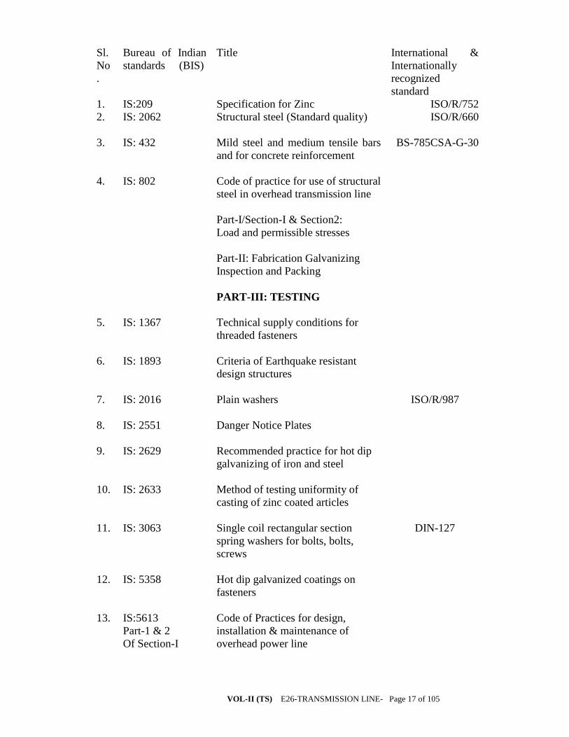
VOL-II (TS) E26-TRANSMISSION LINE- Page 17 of 105
Sl.
No
.
Bureau of Indian
standards (BIS)
Title International &
Internationally
recognized
standard
1. IS:209 Specification for Zinc ISO/R/752
2. IS: 2062 Structural steel (Standard quality) ISO/R/660
3. IS: 432 Mild steel and medium tensile bars
and for concrete reinforcement
BS-785CSA-G-30
4. IS: 802 Code of practice for use of structural
steel in overhead transmission line
Part-I/Section-I & Section2:
Load and permissible stresses
Part-II: Fabrication Galvanizing
Inspection and Packing
PART-III: TESTING
5. IS: 1367 Technical supply conditions for
threaded fasteners
6. IS: 1893 Criteria of Earthquake resistant
design structures
7. IS: 2016 Plain washers ISO/R/987
8. IS: 2551 Danger Notice Plates
9. IS: 2629 Recommended practice for hot dip
galvanizing of iron and steel
10. IS: 2633 Method of testing uniformity of
casting of zinc coated articles
11. IS: 3063 Single coil rectangular section
spring washers for bolts, bolts,
screws
DIN-127
12. IS: 5358 Hot dip galvanized coatings on
fasteners
13. IS:5613
Part-1 & 2
Of Section-I
Code of Practices for design,
installation & maintenance of
overhead power line

VOL-II (TS) E26-TRANSMISSION LINE- Page 18 of 105
14. IS: 6610 Specification for heavy washers for
stell structures.
15. IS: 6745 Methods of determination of weight
of zinc coating of zinc coated iron
and steel articles.
16. IS: 12427 Hexagonal bolts for steel structures
17. INDIAN ELECTRICITY RULES
1956
18. Publication for Regulation for
electrical crossing or railway tracks
1.1.3 The standards mentioned above are available from
Reference/ Name and Address from which
Abbreviation the Standards are available
IS BUREAU OF INDIAN STANDARDS
Manak Bhavan,
9, Bahadur Shah Zafar Marg,
NEW DELHI(India)
ISO INTERNATIONAL ORGANISATION FOR
STANDARDISATION,
Danish Board Standardisation,
Danish Standardisening Street,
Aurehoegbvej-12,
DK-2900, Helleprup, DENMARK
CSA CANADIAN STANDARD ASSOCIATION
178, Rexdale Boulevard, Rexdale,
Ontario, CANADA
M9W IR
BS BRITISH STANDARDS
British Standard Institution,
101, Pentonvile Road,
N-19-ND-UK
DIN DEUTSCHES INSTITUTE FIIR NOR
Gurggrafenstrasse 5-10
Post Fach 1107
D-1000, Berlin – 30
INDIAN
ELECTRICITY
RULES
KITAB MAHAL
1956, REGULATION
FOR
Baba Kharak Singh Marg,

VOL-II (TS) E26-TRANSMISSION LINE- Page 19 of 105
ELECTRICAL
CROSSING OF
NEW DELHI – 110 001
RAILWAY TRACKS (INDIA)
1.1.4 PRINCIPAL PARAMETERS
1.1.5 Electrical System Date:
a) System voltage (kV rms) 400/220/132
b) Max. voltage (kV rms) 420/245/145
c) Lightning impulse withstand voltage
(dry & wet) (kVp)
1550/1050/650
d) Power frequency withstand voltage
(wet) (KV rms)
630/395/275
e) Short circuit level
(KA for 1 sec.
40/40/31.5
1.1.6 Line data
1.1.7 Conductor
a) Name ACSR
Zebra
ACSR
Moose
ACSR
Panther
b) Strength & wire dia
i) Aluminium 54/3.18 54/3.53 30/3.00
ii) Steel 7/3.18 7/3.53 7/3.0
c) Conductors per phase
1) 400 KV
2)220 KV
3)132 KV
Single
Double
Single
d) Spacing between the conductors
of same phase (sub-conductor
spacing) (mm)
---- As per
standard
----
e) Inter-phase spacing (mm)
8,400 8,400 6800
f) Configuration

VOL-II (TS) E26-TRANSMISSION LINE- Page 20 of 105
i) Single circuit Delta Delta Delta
ii) Double circuit Vertical Vertical Vertical
g) Nominal Aluminium area (mm²) 420 528.5
212.1
h) Section area of Aluminium
(mm²)
428.90 597
261.5
i) Total sectional area (mm²) 484.50 597 262
j) Calculated resistance at 20 c
(Max.) ohm/km per conductor
0.06915 0.05552 0.140
k) Approx. calculated breaking
load (KN)(Minimum)
130.32 161.2 89.67
l) Modulus of elasticity (GN/M²)
69 69 82
m) Co-efficient of linear exp. Per
degree cent.
19.3X10⁻⁶
19.3X10⁻⁶
17.8X10-
6
n) Mass of zinc in gms/sqm
……………… 275………………
o) Overall diameter (mm)
28.62 31.77 21.00
p) Weight (kg/km) 1621 2004 974
q) Minimum ultimate tensile
strength (KN)
130.32 161.2 89.67
r) Conductor tension at 32˚ C
without external load
i) Initial unloaded tension
………………..35%………………
ii) Final unloaded tension
…………………25%…………….
1.1.8 Galvanized Steel Ground Wire
a) Size (no. of strands/strand dia) 7/3.15 for 132 and 220 KV, and
7/3.66 for 400 KV
b) Overall diameter (mm) 9.45(7/3.15) and 10.98(7/3.66)

VOL-II (TS) E26-TRANSMISSION LINE- Page 21 of 105
c) Standard weight (Kg/km) 432(7/3.15) and 583(7/3.66)
d) Location of ground wire One continuous ground wire
Wire to run horizontally on the
top of the towers for 132 and
220 KV and two ground wire for
400 KV lines.
e) Tensile load in each ground wire
(to be furnished by the Bidder)
i) At min. temp. of 5˚ C and in still
air (kgs)
ii) At every day temp. of 32˚ C and
still air (kgs)
iii) At 5˚ C and 2/3rd
of full wind
(kgs)
1.1.8.1 Towers
a) Span lengths in metres
ACSR
Zebra
ACSR
Moose
ACSR
Panthe
r
i) Ruling design span 300 300 250
b) Wind load (kg/sqm) on conductor
52 52 52
c) Shielding angle with vertical
20˚ 20˚ 20˚
d) Towers to be designed for heavy
wind zone
V-zone V-zone v-zone
1.1.8.2 Insulator Strings(Disc)(Antifog type)
Sl.
No.
Particulars Single
Suspensi
on string
Double
suspension
string
Single
Tension
string
Double
Tension
string
1. No. of standard Discs
(nos)
1) 400 KV
2) 220 kV
3) 132 Kv
1X25
1X15
1X10
2X25
2X15
2X10
1X25
1X15
1X10
2X25
2X15
2X10
2. Size of Disc
(400kv/220kV/132 kv)
280x145/
255X145/
255X145
280x145/
255X145/
255X145
305x170/305x170/280x145
305x170/305x170/280x145
3. Electromechanical
strength (KN)
(400 KV/220 kV/132
120/90/9
0
120/90/90 160/160/
120
160/160/12
0

VOL-II (TS) E26-TRANSMISSION LINE- Page 22 of 105
KV)
4.0 GENERAL TECHNICAL REQUIREMENTS
4.1 Tower Design – General
The employer is looking for a structurally safe design of transmission line
towers to be installed on EHV lines keeping the loadings and line parameters
detailed in this specification and in compliance with IS: 802 (Part-1/Sec-1)-
1995, IS: 802(Part-1/Sec-2)-1992.
The Bidder may offer economical designs with rational sections or offer towers
of recent design, proven in service and accepted by other reputed Central and
State Sector Utilities and by OPTCL (Previously OSEB) confirming to this
technical specification. The technical particulars for vibration analysis and damping design of the system are as follows:
FOR 400kV LINES.
-------------------------------------------------------------------------------------------------------- --
SL. Description Technical Particulars
No.
----------------------------------------------------------------------------------------------------------
1. Configuration Double Circuit Twin ACSR Moose 54/7//3.53 mm, conductor bundle per phase in horizontal formation and all three phases of each circuit in vertical configuration on each side of tower.
2. Span length in meters
(i) Ruling design 400 meters
span (ii) Maximum span 1100 meters (iii) Minimum span 100 meters
3. Tensile load in each sub-conductor Wind Zone : 5 (50 m/s). for ruling span a) At temperature 3267 Kgf. of 5 deg-C and still air b) At temperature 4646 Kgf. of 5 deg.C and 36% full wind c) At temperature 7805 Kgf. of 32 deg.C and full wind 4. Armour rods used Standard preformed armour

VOL-II (TS) E26-TRANSMISSION LINE- Page 23 of 105
rods/AGS 5. Maximum permissible +/- 150 micro strains dynamic strain
FOR 220 kV and 132 kV LINES
-------------------------------------------------------------------------------------------------------
SL.NO. Description Technical Particulars
-------------------------------------------------------------------------------------------------------
220kV 132kV ACSR ZEBRA ACSR PANTHER 54/7/ 3.18mm 30/7/3.0mm
1. Configuration Double Circuit Double Circuit Single ACSR Single ACSR conductor per conductor per phase in verti- phase in verti-
cal formation cal formation
2. Span length in metres (I) Ruling design 350 metres 300 metres span (ii) Maximum span 1100 metres 1000 metres (iii) Minimum span 100 metres 100 metres
3. Tensile load in Wind Zone:5 Wind Zone:5 each conductor (50 m/s.) (50 m/s.) for ruling span a) At temperature 2919 Kgf. 1791Kgf. of 5 deg.C and still air b) At temperature 4090 Kgf. 2735Kgf. of 5 deg.C and 36% full wind c) At temperature 6551 Kgf. 4469 Kgf. of 32 deg-C and full wind 4. Armour rods used Standard performed Standard performed armour rods/AGS armour rods/AGS 5. Maximum permissible ± 150 micro- ± 150 micro- dynamic strain strains strains
4.0 DETAILS OF SOLID CORE LONG ROD INSULATORS: 5.1 The insulator shall consist of standard-discs for a three-phase 50 Hz
effectively earthed 220 KV transmission system heavily polluted atmosphere. The insulator shall be ball and socket type.
5.1 The size of long rod insulator, minimum creepage distance, the number to be used in different type of strings, their electromechanically strength and mechanical strength of insulator string alongwith hardware shall be as follows:

VOL-II (TS) E26-TRANSMISSION LINE- Page 24 of 105
Sl. No.
Type of string.
Size of long rod insulator (mm)/(Unit) 132/220 KV
Minimum creepage distance (mm) 132/220 KV
No.of unit 132/220 KV)
Electromechanical strength of insulator (KN) 132/220 KV)
1.
Single suspension
200X 1305
/210X2030
4000 /
6125
'1/2 90 KN
2.
Double suspension
-do- -do- '2/4 90 KN
3.
Single tension.
205 X 1450 /
215X2550
4300/7130 '1/2 120 KN/160 KN
4.
Double Tension.
-do- -do- '2/4 120 KN/160 KN
5.0 SPECIFICATION DRAWINGS: 6.1 A list of specification drawings in respect of the long rod insulators
indicated above is given at Annexure-II. These specification drawings are attached herewith for information and guidance of the bidder only. The drawings to be furnished by the supplier shall be as per his own design and manufacture and shall be distinct and separate from these specification drawings.
6.0 GENERAL TECHNICAL REQUIREMENT: 7.1 PORCELAIN:
The porcelain used in the manufacture of the shell shall be ivory white, nonporous of high dielectric, mechanical and thermal strength free from internal stress blisters and thermal strength from internal stresses blisters, laminations, voids, foreign matter. Imperfections or other defects, which might render it in any way unsuitable for insulator shells. Porcelain shall remain unaffected by climatic conditions, ozone, acid alkalis, and zinc of dust. The manufacturing shall be by the wet process and impervious character obtained by through vetrification.
7.2 PORCELAIN GLAZE:
Surfaces to come in contact with cement shall be made rough by stand glazing. All other exposed surfaces shall be glazed with ceramic materials having the same temperature coefficient of expansion as that of the insulator shell. The thickness of the glaze shall be uniform throughout and the colour of the glaze shall be brown. The glaze shall have a visible luster and smooth on surface and be capable of satisfactory performance under extreme tropical climatic weather conditions and prevent ageing of the porcelain. The glaze shall remain under compression on the porcelain body throughout the working temperature range.
7.3 METAL PARTS:

VOL-II (TS) E26-TRANSMISSION LINE- Page 25 of 105
7.3.1 Cap and Ball pins: Twin Ball pins shall be made with drop forged steel and caps with malleable cast iron. They shall be in one single piece and duly hot dip g galvanized. They shall not contain parts or pieces joined together, welded, shrink fitted or by any other process from more than one piece of material. The pins shall be of high tensile steel, drop forged and heat malleable cast iron and annealed. Galvanizing shall be by the hot dip process with a heavy coating of zinc of very high purity with minimum of 6 dips. The bidder shall specify the grade, composition and mechanical properties of steel used for caps and pins.
7.3.2 SECURITY CLIPS: The security clips shall be made of phosphor bronze or of stainless steel. 7.4 FILLER MATERIAL: Cement to be used as a filler material shall be quick setting, for curing Portland cement. It shall not cause fracture by expansion or loosening by contraction. Cement shall not react chemically with metal parts in contract with it and its thickness shall be as small and as uniform as possible. 7.0 MATERIAL DESIGN AND WORKMANSHIP: 8.1 GENERAL: i) All raw materials to be used in the manufacture of these insulators shall be subject to strict raw materials quality control and to stage testing quality control during manufacturing stage to ensure the quality of the final end product. Manufacturing shall conform to the best engineering practices adopted in the field of extra high voltage transmission. Bidders shall therefore offer insulators as are guaranteed by them for satisfactory performance on Transmission lines. ii) The design, manufacturing process and material control at various stages be such as to give maximum working load, highest mobility, best resistance to corrosion good finish, elimination of sharp edges and corners to limit corona and radio interference voltage 8.2 INSULATOR SHELL:
The design of the insulator shell shall be such that stresses due to expansion and contraction in any part of the insulator shall not lead to deterioration. Shells with cracks shall be eliminated by temperature cycle test followed by temperature cycle test followed by mallet test. Shells shall be dried under controlled conditions of humidity and temperature.
8.3 METAL PARTS: a) The twin ball pin and cap shall be designed to transmit the mechanical stresses to the shell by compression and develop uniform mechanical strength in the insulator. The cap shall be circular with the inner and outer surfaces concentric and of such design that it will not yield or distort under loaded conditions. The head portion of the insulator or is under tension the stresses are uniformly distributed over the pinhole portion of the shell. The pinball shall

VOL-II (TS) E26-TRANSMISSION LINE- Page 26 of 105
move freely in the cap socket either during assembly of a string or during erection of a string or when a string is placed in position. b) Metal caps shall be free from cracks, seams, shrinks, air holes, blowholes and rough edges. All metal surfaces shall be perfectly smooth with no projecting parts or irregularities which may cause corona. All load bearing surfaces shall be smooth and uniform so as to distribute the loading stresses uniformly. Pins shall not show any macroscopically visible cracks, insulations and voids. 8.4 GALVANIZING:
All ferrous parts shall be hot dip galvanized six times in accordance with IS: 2629. The zinc to be used for galvanizing shall conform to grade Zn 99.5 as per IS: 209. The zinc coating shall be uniform, smoothly adherent, reasonably light, continuous and free from impurities such as flux ash, rust stains, bulky white deposits and blisters. Before ball fittings are galvanized, all die flashing on the shank and on the bearing surface of the ball shall be carefully removed without reducing the designed dimensional requirements.
8.4.1 CEMENTING:
The insulator design shall be such that the insulating medium shall not directly engage with hard metal. The surfaces of porcelain and coated with resilient paint to offset the effect of difference in thermal expansions of these materials.
8.5 SECURITY CLIPS (LOCKING DEVICES
The security clips to be used as locking device for ball and socket coupling shall be ‘R’ shaped hump type to provide for positive locking of the coupling as per IS: 2486 (Part-IV). The legs of the security clips shall allow for sore adding after installation to prevent complete withdrawal from the socket. The locking device shall be resilient corrosion resistant and of sufficient mechanical strength. There shall be no possibility of the locking device to be displaced or be capable of rotation when placed in position and under no circumstances shall it allow separation of insulator units and fitting ‘W’ type security clips are also acceptable. The hole for the security clip shall be countersunk and the clip shall be of such design that the eye of the clip may be engaged by a hot line clip puller to provide for disengagement under energized conditions. The force required for pulling the clip into its unlocked position shall not be less than 50 N (5 Kgs.) or more than 500N (50 Kgs.)
8.6 BALL AND SOCKET DESIGNATION:
The dimensions of the balls and sockets for 80 KN long rod insulators shall be of 16mm and for 120 KN shall be of 20mm designation in accordance with the standard dimensions stated in IS: 2486 (Part-III).
8.7 DIMENSIONAL TOLERANCE OF INSULATORS DISCS

VOL-II (TS) E26-TRANSMISSION LINE- Page 27 of 105
It shall be ensured that the dimensions of the long rod insulators are within the limits as per relevant IEC/ISS. Bundle spacer (only for 400kV lines )
Armour grip bundle spacers shall be used to maintain the spacing of 450 mm between
the two sub-conductors of each bundle under all normal working conditions.
Spacers offering equivalent or better performance shall also be accepted provided offer
meets the qualifying requirements stipulated in the Specification.
The offer shall include placement charts recommending the number of spacers per
phase per span and the sub span lengths to be maintained between the spacers while
installing on the twin bundle conductors.
The placement of spacers shall be in such a way that adjacent sub spans are sufficiently
detuned and the critical wind velocity of each sub span shall be kept more than 30
km/hr and to avoid clashing of sub conductors. The placement shall ensure bundle
stability under all operating conditions.
The placement chart shall be provided for spans ranging from 100m to 1100m. The
number of spacers recommended for a nominal ruling span of 400m shall however be
not-less than six.
The Bidder shall also furnish all the relevant technical documents in support of their
placement charts along with the Bid.
Jumpers at tension points shall also be fitted with spacers so as to limit the length of
free conductor to 3.65 m and to maintain the sub conductor spacing of 450 mm. Bidder
shall quote for rigid spacer for jumper. It shall meet all the requirements of spacer used
in line except for its vibration performance. Spacers requiring retaining rods shall not
be quoted for jumpers. For slack span also rigid spacers shall be used with
maximum spacing of 30 metres.
The spacer offered by the Bidder shall satisfy the following requirements:
Spacers shall restore normal spacing of the subconductors after displacement by wind,
electromagnetic and electrostatic forces under all operating conditions, including the
specified short circuit level, without permanent deformation or damage either to
conductor or to the assembly itself. They shall have uniform grip on the conductors.
For spacers requiring preformed retaining rods, the retaining rods shall be designed for
the specified conductor size. The rods shall be made of high strength special aluminium
alloy of type 6061 or equivalent aluminium alloy having minimum tensile strength of
35 kg/sqmm. The ends of retaining rods shall be ball ended. The rods shall be heat-
treated to achieve specified mechanical properties and give proper resilience and retain
the same during service.
Four rods shall be applied on each clamp to hold the clamp in position. The minimum
diameter of the rods shall 7.87 +/- 0.1 mm. and the length of the rods shall not be less
than 1100 mm.
Where elastomer surfaced clamp grooves are used, the elastomer shall be firmly fixed
to the clamp. The insert shall be forged from aluminium alloy of type 6061 or
equivalent aluminium alloy having minimum tensile strength of 35 kg/sqmm. The
insert shall be duly heat treated and aged to retain its consistent characteristics during
service.
Any nut used shall be locked in an approved manner to prevent vibration loosening.
The ends of bolts and nuts shall be properly rounded for specified corona performance
or suitably shielded. Clamp with cap shall be designed to prevent its cap from slipping
out of position when being tightened. The clamp grooves shall be in uniform contact
with the conductor over the entire clamping surface, except for rounded edges. The

VOL-II (TS) E26-TRANSMISSION LINE- Page 28 of 105
groove of the clamp body and clamp cap shall be smooth and free of projections, grit or
other material, which may cause damage to the conductor when the clamp is installed.
For the spacers involving bolted clamps, the manufacturer must indicate the clamp bolt
tightening torque to ensure that the slip strength of the clamp is maintained between 2.5
kN and 5kN. The clamp when installed on the conductor shall not cause excessive
stress concentration on the conductor leading to permanent deformation of the
conductor strands and premature fatigue failure in operation. Universal type bolted
clamps, covering a range of conductor sizes will not be permitted. No rubbing, other
than that of the conductor clamp hinges or clamp swing bolts shall take place between
any parts of the spacer. Joints incorporating a flexible medium shall be such that there
is no relative slip between them.
The spacer shall be suitably designed to avoid distortion or damage to the conductor or
to themselves during service. Rigid spacers shall be acceptable only for jumpers. The
spacer shall not damage or chafe the conductor in any way which might affect its
mechanical and fatigue strength or corona performance. The clamping system shall be
designed to compensate for any reduction in diameter of conductor due to creep. The
spacer assembly shall not have any projections, cuts, abrasions or chattering parts
which might cause corona or RIV. The spacer tube shall be made of aluminium alloy of
type 6061 or equivalent aluminium alloy. If fasteners of ferrous material are used, they
shall conform to and be galvanised conforming to relevant Indian Standards. The
spacers involving ferrous fasteners shall not have magnetic power loss more than one
watt at 600 amps., 50 Hz alternating current per subconductor. Elastomer, if used, shall
be resistant to the effects of temperature up to 85 deg.C, ultraviolet radiation and other
atmospheric contaminants likely to be encountered in service. It shall have good
fatigue characteristics. The physical properties of the elastomer shall be of approved
standard. The electrical resistance between the sub-conductor across the assembly in
case of spacer having elastomer clamp grooves shall be suitably selected by the
manufacturers to ensure satisfactory electrical performance and to avoid deterioration
of elastomer under all service conditions.
The spacer assembly shall have complete ease of installation and shall be capable of
removal and reinstallation without any damage. The spacer assembly shall be capable
of being installed and removed from the energised line by means of hot line techniques.
Spacer damper (only for 400kV lines )
As an alternative to vibration dampers and bundle spacers combination, suitable spacer
dampers for twin bundle AAAC 61/3.45 conductor may be offered. The spacer damper
covered by this Specification shall be designed to maintain the bundle spacing of
450mm under all normal operating conditions and to effectively control aeolian
vibrations as well as subspan oscillations to nominal conductor spacing after release of
any external extra-ordinary load.
The spacer damper shall restore the normal subconductor spacing due to displacement
by wind, electromagnetic and electrostatic forces including the specified short circuit
level without permanent deformation or damage either to bundle conductors or to
spacer damper itself.
The design offered shall be presented as a system consisting of a recommended number
of spacer dampers together with their spacing schedule for spans ranging from 100m to
1100 m.
Under the operating conditions specified, the spacer damper system shall adequately
control Aeolian vibrations throughout the life of the transmission line in order to

VOL-II (TS) E26-TRANSMISSION LINE- Page 29 of 105
prevent damage to conductor at suspension clamps, dead end clamps and at the spacer
clamps.
The spacer damper system shall also control the sub span oscillations in order to
prevent conductor damage due to chafing and due to severe bending stresses at the
spacer damper clamps as well as suspension and dead end clamps and to avoid wear to
spacer damper components.
The spacer damper shall consist of a rigid central body called the frame, linked to the
conductors by two articulated arms terminated by suitable clamping system. The
dynamic characteristics of the articulations shall be maintained for the whole life of the
transmission line.
The clamping system shall be designed to provide firm but gentle and permanent grip
while protecting the conductor against local static or dynamic stresses expected during
normal operating conditions. The clamping system shall be designed to compensate for
any reduction of conductor diameter due to creep.
The clamp of the spacer damper, when installed, shall not cause excessive stress
concentration on the conductor leading to permanent deformation of the conductor
strands and premature fatigue failure in operation. The slip strength of the clamp shall
be maintained between 2.5kN to 5kN. The tightening torque for the bolts, if applicable,
shall be specified by the manufacturer to achieve the above slip strength.
Bolted type clamps shall allow installation without removal of the bolts or the clamps
from clamp body. Locking mechanism shall be suitable to prevent bolt loosening.
Clamp locking devices using small loose components shall not be accepted.
Bolts and nuts shall be of mild steel, stainless steel, or high strength aluminium
alloy in accordance with the design of the spacer damper.
Where elastomer surfaced clamps are used, the elastomer elements shall be firmly fixed
to the clamp. The insert should be forged from aluminium alloy of type 6061 or
equivalent aluminium alloy having minimum tensile strength of 35 kg/sqmm. The
insert shall be moulded on the insert surface. The insert shall be duly heat treated and
aged to retain its consistent characteristics during service. The grain flow of the forged
insert shall be in the direction of the maximum tension and compression loads
experienced.
If clamps involving preformed rods are used, these rods shall be designed for
specific conductor size. They shall be made of high strength aluminium alloy of type
6061 or equivalent aluminium alloy having a minimum tensile strength of 35
kg/sqmm. The rods shall be ball ended. The rods shall be heat treated and aged to
achieve specified mechanical properties and to retain the same during service.
The spacer damper body shall be cast/forged from suitable high strength
corrosion resistant aluminium alloy. The aluminium alloy shall be chosen in relation
with the process used. However a combination of aluminium alloy and steel shall also
be accepted.
The rubber components like damping elements involved in the design shall be
made with rubber compound selected specifically for that particular application. The
Bidder shall submit a complete list of physical and mechanical properties of the
elastomer used. This list shall make reference to all applicable ASTM or other
Internationally recognised standards.
The rubber compounds used shall have good resistance to the effects of
temperature up to 85 deg.C and to ultra violet radiation, ozone and other atmospheric
contaminants. The rubber shall have good wear and fatigue resistance and shall be
electrically semi-conductive.

VOL-II (TS) E26-TRANSMISSION LINE- Page 30 of 105
The spacer damper involving ferrous material shall not have magnetic power
loss more than one watt at 600 amps., 50 Hz alternating current per sub conductor.
The spacer damper assembly shall have electrical continuity. The electrical
resistance between the subconductors across the assembly in case of spacer damper
involving elastomer surfaced clamps shall be suitably selected by the manufacturer to
ensure satisfactory electrical performance and avoid deterioration of elastomer under
service conditions.
The spacer damper assembly shall have complete ease of installation and shall
be capable of removal and reinstallation without any damage.
The spacer damper assembly shall be capable of being installed and removed
from the energised line by means of hot line techniques.
The Bidder shall recommend the spacing between spacer dampers on the line which
shall ensure the most satisfactory fatigue performance of the line as specified. The
scheme shall indicate the number of spacer dampers per phase per span and the sub-
span lengths to be maintained between spacer dampers when installed on the twin
bundle conductors.
The number of spacer dampers and their spacing shall be provided for spans
ranging from 100 to 1100m. The number of spacer dampers for a nominal ruling span
of 400 m shall be not less than six.
No sub-span shall be greater than 70m and no end sub-span shall be longer than
40 metres.
The proposed scheme shall be such that the spacer dampers be unequally
distributed along the span to achieve sufficient detuning of adjacent sub-spans for
oscillations of sub-span mode and to ensure bundle stability for wind speeds up to 30
kms/hr (8.33 m./sec.).
The Bidder shall furnish all the relevant technical documents in support of the
staggering scheme recommended for the spacer damper.
The Bidder in the latter case shall forward documentation of proto type tests
conducted and acceptance given by the user authorities as also performance
report for such towers in service.
Vibration dampers All the requirements for vibration damper suitable for line conductors, shall
also be applicable for galvanised steel earthwires (7/3.66mm. for 400kV and 7/3.15mm.
for 220kV/132kV lines). Minimum one damper on each side per earth wire at
suspension point and two dampers on each side at tension point shall be used for ruling
design span. Bidders may offer damping systems involving a greater number of
dampers for ruling design span; however, suitable price compensation shall be
considered for evaluation.
The vibration analysis of the system, with and without dampers, dynamic characteristic
of the damper as detailed shall be submitted by the Bidder along with his bid. The
technical particulars for vibration analysis and damping design of the system are as
follows :
For 400kV Lines
---------------------------------------------------------------------------------------------------------
---
Sl. No. Description Technical Particulars
---------------------------------------------------------------------------------------------------------
--

VOL-II (TS) E26-TRANSMISSION LINE- Page 31 of 105
1. Configuration Two galvanised steel earthwires in horizontal configuration 2. Span length in meters Ruling design span 400 meters Maximum span 1100 meters Minimum span 1 00 meters 3. Tensile load in each Wind Zone : 5
earthwire for ruling span (50m/s)
a) At temperature of 5o C and still air 1368 Kgf b) At temperature of 5o C and 36% full wind 2056 Kgf c) At temperature of 32o C and full wind 3593 Kgf 4. Maximum permissible dynamic strain +/- 150 micro strains
For 132kV and 220kV Lines
---------------------------------------------------------------------------------------------------------
---
Sl. No. Description Technical Particulars
---------------------------------------------------------------------------------------------------------
---
1 . Configuration One galvanised steel earthwire in horizontal configuration . 2. Span length in meters 220 kV Line 132 kV Line Ruling design span 350 meters 300 meters Maximum span 1100 meters 1000 meters Minimum span 100 meters 100 meters 3. Tensile load in Wind Zone:5 Wind Zone:5 each earthwire (50m/s) (50m/s) for ruling span a) At temperature 1120 Kgf. 1120 Kgf. of 5 deg.C and still air b) At temperature 1667 Kgf. 1606 Kgf. of 5 deg.C and

VOL-II (TS) E26-TRANSMISSION LINE- Page 32 of 105
36% full wind c) At temperature 2815 Kgf. 2625 Kgf. of 32 deg.C and full wind 4 . Maximum permissible +/- 150 micro +/- 150 micro dynamic strain strains strains
Flexible copper bond At suspension and tension towers the earth wire suspension and tension clamps
shall be securely bonded to the tower steelwork by means of a multi-strand flexible
copper bond wire. The copper bond shall be sufficiently flexible to allow movement of
the suspension clamp under all operating conditions and terminated with compression
lugs.
The flexible copper bond shall be of nominal 34 sq.mm equivalent copper area and not
less than 500 mm in length. It shall consist of 259 wires of 0.417 mm dia. tinned copper
conductor. It shall be laid up as seven stranded ropes, each of 37 bunched wires. The
tinning shall be as per IS 9567. Two tinned copper connecting lugs shall be press
jointed to either ends of the flexible copper cable. One lug shall be suitable for 12 mm,
dia. bolt and the other for 16 mm dia. bolt. The complete assembly shall also include
one 16 mm dia., 40 mm long mild steel bolt hot dip galvanised with nut and lock
washers
Arcing horn
The arcing horn shall be either ball ended rod type or tubular type and shall be formed from galvanised
mild steel and of approved types. The arcing horns shall be attached in an approved manner to all
suspension and tension insulator sets. The horns shall be attached to the insulator fittings, but not directly
to conductor clamps or to the caps of insulator units. The design of the arcing horns shall be such as to
reduce, as far as reasonably possible, damage to the line conductors, clamps, insulator strings and arcing
horns themselves under all flashover conditions. The general shape and method of attachment of the live
end arcing horn shall also not restrict the replacement of insulators under live line conditions.
The total effective arcing distance shall be 1530mm., 2130mm. and 3050 mm. for 132kV, 220kV and
400kV respectively under nominal dimensions of insulator.
Arcing horns shall be provided on tower and/or line side as indicated on the enclosed string sketches,
however, same has been tabulated below for ready reference :
-------------------------------------------------------------------------------------------- -----------------------
SL.No. Voltage Types of Strings Arcing horns to Min. Arcing dist.
Level be provided on to be maintained(mm)
-------------------------------------------------------------------------------------------------------------------
1. 2. 3. 4. 5.
1. 132kV Single ‘I’ suspen- Line side only 1530(for132kV)& and sion strings 2130(for 220kV) 220kV
1. 2. 3. 4. 5.
2. -do- Double suspens- Both on line side 1530(for132kV)& ion strings and tower side 2130(for 220kV)

VOL-II (TS) E26-TRANSMISSION LINE- Page 33 of 105
3. -do- Single tension Line side only -do- strings 4. -do- Double tension Both on line side -do- strings and tower side 5. 400kV Single ‘I’ suspen- Tower side (coro- 3050 sion and pilot na/grading rings strings on line side ) 6. -do- Double suspen- -do- -do- sion strings 7. -do- Single tension -do- -do- strings 8. -do- Double tension -do- -do- strings --------------------------------------------------------------------------------------------------------------------
4.1.1 Transmission Towers
4.1.2 General Description
The towers shall be of the following types:
(b) Double Circuit (A, B, C & D)
(c) Special Towers (River Crossing, Railway Track Crossing, Power Line Crossing
etc.)
Types Of Towers
The towers shall normally be of the following standard types, and as stated in
Schedule C.
---------------------------------------------------------------------------------------------------------
--
Type of Tower Deviation Limit Typical Use
(1) (2) (3)
---------------------------------------------------------------------------------------------------------
---
DA/OA/PA 0deg- 2deg a) To be used as tangent tower with suspension strings. b) Also to be designed for specified broken wire conditions. DB /0B/PB 0 deg- 15deg a) Angle towers with tension insulator string b) Also to be designed for unbalanced tension resulting from unequal ruling span of 400m and 200m (for 400kV), of 350m and 250m

VOL-II (TS) E26-TRANSMISSION LINE- Page 34 of 105
(for 220kV) and of 300m and 200m (for 132kV )on each side of the tower. c) Also to be designed for uplift forces resulting from an up-lift span of 200m under broken wire conditions. d) Also to be designed for specified broken wire conditions. e) Also to be designed for anti- cascading condition. DB/OB/PB 0 deg. f) To be used as section tower. DC/OC/PC 15 deg-30 deg. a) Angle tower with tension insulator strings. b) Also to be designed for unbalanced tension resulting from unequal ruling span of
400m and 200m (for 400kV),
of 350m and 250m (for 220kV )
and of 300m and 200m (for
132kV )on each side of the tower.
c) Also to be designed for uplift forces resulting from an up-lift span of 200m under broken wire conditions. d) Also to be designed for specified broken wire conditions. e) Also to be designed for anti-cascading condition. DC/OC/PC 0 deg. f) To be used as transposition tower with modifications (only where specified) DD 30 deg-60 deg a) Angle tower with tension insulator string

VOL-II (TS) E26-TRANSMISSION LINE- Page 35 of 105
b) Also to be designed for the unbalanced tension resulting from unequal ruling span of 400m and 200m (for 400kV), of 350m and 250m (for 220kV) and of 300m and 200m (for 132kV) on each side of the tower. c) Also to be designed for uplift forces resulting from an uplift span of 300m(for 400kV) and 200m (for 132kV and20kV) under broken wire conditions. d) Also to be designed for specified broken wire conditions. e) Dead end with 0 deg to 15 deg deviation on line and 0 deg to 30 deg for sub-station side (slack span side). DD 0 deg f) Complete dead end.
g) For river crossing anchoring with
longer wind span with 0 deg deviation
on crossing span side and 0 deg to 30
deg deviation on other sides .
Note: The above towers can also be used for longer span with smaller angle of deviations. (To be decided as per the tower spotting data to be submitted by the Contractor and approved by Project Manager.)
4.1.3 The towers shall be of the self-supporting type, built up of lattice steel sections
or members and designed to carry the power conductors with necessary insulators.
Ground wires and all fittings under all loading conditions. Outline diagrams of the
towers required are to be furnished by the Bidder.
4.1.4 The towers shall be fully galvanized structures built up of structural mild steel
sections. All members shall be connected with bolts, nuts and spring washers.
For design of structure weight span limits given in Table 5.1 shall prevail.
TABLE 5.1 (a)
For 132 kV Line
Tower Normal Condition Broken Wire Cond Type Max. Min. Max. Min. (m) (m) (m) (m)
DA 450 150 270 100

VOL-II (TS) E26-TRANSMISSION LINE- Page 36 of 105
DB, DC & DD 450 0 270 -200
TABLE 5.1 (b)
For 220 kV Line
Tower Normal Condition Broken Wire Cond Type Max. Min. Max. Min. (m) (m) (m) (m)
DA 525 200 315 100
DB, DC & DD 525 0 315 -200
TABLE 5.1 (c)
For 400 kV Line
Tower Normal Condition Broken Wire Con Type Max. Min. Max. Min. (m) (m) (m) (m)
DA 600 200 360 100 DB, DC 600 0 360 -200 DD 600 0 360 -300
However, for calculating the tower height, an allowance of 150mm shall be provided,
over and above the specified ground clearances, at still air and maximum conductor
temperature, to account for any stringing error.
TABLE
Minimum clearance
Situation (metres)
System voltage (kV): 132 220 400 Normal ground (open country) 6.10 7.015 8.84 * Road crossings, road level 7.00 7.90 9.7 Rail crossings, rail level: 17.9 17.9 19.3 River crossings, bank level River crossings, navigable rivers, above highest as specified by the Authority flood level;(data to be obtained from Navigation Authority) Above trees 4.0 4.6 5.5 Buildings, poles, structures and walls, etc. upon which a man may stand : horizontal clearance 4.6 5.5 7.3 Same above : vertical clearance 2.9 3.8 5.6 Power lines 3.1 4.6 6.1
*Any road which is normally maintained by Government and/or other recognised public authority.

VOL-II (TS) E26-TRANSMISSION LINE- Page 37 of 105
4.1.5 Stubs and Superstructures:
(i) The stub shall mean a set of four stub angles fully galvanized from the
and shall include cleats, gussets, bolts and nuts, etc. the black portion of
the stub being cast in foundation footings. Stub length shall correspond
to foundation depth of 3-0 metres from ground level.
(ii) Superstructure shall mean the galvanized tower assembly above the stubs which
includes structural members like angle sections, cross arms, ground wire peaks,
accessories and fittings such as gusset plates, pack washers, spring, washers, ladders,
step bolts, anti climbing devices and such other items which are required for
completing the towers in all respect. Steel and zinc required for manufacturing these
items will be arranged by the supplier.
(iii) Supply of bolts and nuts and spring washers, hangers/D-shackles for attaching
suspension strings and ‘U’ bolts for attaching ground wire suspension assemblies are
included in the supply of tower.
(iv) The following provisions shall apply in connection with the procurement of
steel and zinc by the supplier.
(a) The steel used for fabrication of tower parts extensions, templates etc. shall be
of mild steel of tested quality as per IS:2062 GRA.
(b) The Bidder shall take into account the fabrication wastage while quoting the
rates. The employer will not accept any liability in connection with the wastage of steel
during fabrication or otherwise.
(c) The Bidder shall indicate in his offer the sizes of steel sections which are
proposed to be used by him in the design of towers.
(d) Substitutions, if any, of steel sections of the tower parts by higher sizes, due to
non-availability or otherwise shall be to the supplier’s account. The employer will not
accept any liability on this account.
(e) The steel shall be procured exclusively from the main steel producers. However,
sections not rolled by main producers, can be procured from re-rollers provided.
Re-rolling of structural steel sections is done from billets/ingots of tested quality.
Re-rolled sections are duly tested as per relevant standard.
(f) The zinc used for galvanizing fabricated material shall be of High Grade
Electrolytic zinc.
4.1.6 Extensions:
a) The towers shall be designed so as to be suitable for adding 3 metres, 6 metres,
9 metres extensions for maintaining adequate ground clearances without reducing the
specified factor of safety in any manner.
VOL-II (TS) E26-TRANSMISSION LINE- Page 38 of 105
b) The Buidder shall have to design leg extensions for all types of towers ranging
from minus 3 metres to plus 9 metres at intervals of 1.5 metres and such leg extensions
shall be suitable for being fitted to a normal tower as well as a tower with extensions.
This is to enable tower spotting in hilly terrain.
4.1.7 Stub setting Templates:
Stub templates shall be designed and supplied by the supplier as per
requirement for all types of towers with or without extensions. Stub
templates for standard towers and towers with extension shall be fined type.
The stub templates shall be painted with anti-corrosive paints.
4.1.8 Fasteners: Bolts, Nuts & Washers
4.1.9 All bolts shall be of property class 5.6 and nuts of property class 5.0 IS: 1367
(Part – 3) 1991 and IS: 6639-1972 shall conform to IS: 12427, they shall be galvanized
and shall have hexagonal heads and nuts, the heads being forged out of solid steel rods
and shall be truly concentric and square with the shank. The shank shall be perfectly
straight.
4.1.10 ully threaded bolts shall not be used, the length of bolts should be such that the
threaded portion shall not extend into the place of contact of the members.
4.1.11 ll bolts shall be threaded to take the full depth of the nut and threaded far
enough to permit firm gripping of the members, but not any further. It shall be ensured
that the threaded portion of each bolt protrudes not less than 3 mm and not more than 8
mm when fully tightened. All nuts shall fit hand tight to the point where the shank of
the bolt connects to the head.
4.1.12 lat and tapered washers shall be provided wherever necessary. Spring washers
shall be provided for insertion under all nuts. These washers shall be of electro-
galvanized steel and of the positive lock type. Their thickness shall be 2.5 mm for 12
mm dia bolts, 3.5 mm for 16 mm dia bolts and 4.5 mm for 20 mm dia bolts.
4.1.13 he Bidder shall furnish bolt schedules giving thickness of members connected,
size of bolts and nuts, the length of the shank, the length of the threaded portion of
bolts, sizes of bolt holes, thickness of washers and any other special details of this
nature.
4.1.14 To obviate bending stress in bolts or to reduce it to a minimum, no bolt shall
connect aggregate thickness of more than three (3) times its dia.
4.1.15 he bolt positions in assembled towers shall be as per IS: 5613 (Part-I/Section-I)
(Part-II/Section-2)-1985.
4.1.16 olts at the joints shall be so staggered that nuts may be tightened with spanners
without fouling.
VOL-II (TS) E26-TRANSMISSION LINE- Page 39 of 105
5.0 Tower Accessories
5.1 Step Bolt Ladders: These bolts shall be of property class 4.6 conform to IS:
6639-1972.
5.1.1 Each tower shall be provided with step bolts on one of the main legs, of not less
than 16 mm diameter and 175 mm long, spaced not more than 400 mm apart and
extending from about 2.5 metres above the ground level to the top of the tower. Each
step bolt shall be provided with two nuts on one end to fasten the bolt security to the
tower and button head at the other end to prevent the feet from slipping away. The step
bolts shall be capable of withstanding a vertical load not less than 1.5 KN and shall be
used as a ladder for climbing.
5.1.2 Anti-climbing devices: This shall conform to IS: 5613 (Part-I/Sec –I),
19085.
Fully galvanized barbed wire type anti-climbing device shall be provided at
a height of approximately 3 metres as an anti-climbing measure. Four layers
of barbed wires will be provided each inside and outside the tower in
horizontal plane, spacing between the layers being 140 to 150 mm. The
towers to be designed by the supplier shall have provision to fixed the
barbed wire as indicated above. Thus the angle pieces with notches for
accommodating barbed wire shall be designed and supplied with the towers
along with provision for suitable bolt holes on leg members for fitting bolt
holes on leg member for fitting the angles. The scheme of the anti-climbing
device shall be submitted along with the tower drawing. Barbed wire shall
be included in the scope of bidder.
5.1.3 Insulator strings and ground wire clamp attachments
(a) For the attachment of suspension insulator strings a suitable swinging hanger on
the tower shall be provided so as to obtain requisite clearance under extreme swinging
conditions and free swinging of the string.
The hanger shall be designed to withstand an ultimate tensile
strength of 11.500 kg.
5.1.4 (a)For ground wires at suspension towers suitable ‘U’ Bolts strong enough to
withstand the full designed loads shall be provided to accommodate the hook of the
ground wire suspension clamps.
(b) At tension towers, horizontal strain plates of suitable dimensions on the
underside of each power cross-arm tip and at the top ground wire peak shall be
provided for taking the ‘D’ Shackles of the tension insulator strings or ground wire
tension clamps, as the case may be. Full details of the attachments shall be submitted by
the supplier for the employer’s approval before commencing with mass fabrication.
5.1.5 Phase Plate

VOL-II (TS) E26-TRANSMISSION LINE- Page 40 of 105
Phase plate shall be of mild steel of 16 gauge vitreous enameled at back and
front, circular in shape and diameter 75 mm. One set of phase plate shall be
consisting of 3 plates red, yellow and blue coloured accordingly to indicate
the phase of the conductor. There shall be one fixing bolt on the plate. This
shall conform to IS: 5613 (Part-II/Section01) of latest edition.
5.1.6 Number Plate
The number plate shall be mild steel vitreous enameled at back and front,
200 mmx 150 mm, rectangular shape and inscribed thereon shall be the
number of the tower location preceded by letter corresponding to the short
name of the line and the type of towers. There shall be two fixing bolts on
both end of the plates. The dimension and details of the number plate shall
be as per IS: 5613 (Part-II/Section1 & Section-2), 1985.
5.1.7 Danger Plate
These shall be of mild steel vitreous enameled at back and front 250 x 200
mm rectangular shape and inscribed thereon shall be in signal red the work
‘DANGER’ with its Oriya and Hindi translation and also with the
inscription of Bone and Scull and voltage of the line. There shall be two
holes on the plates for fixing. This shall conform to IS: 2551 (latest edition).
5.1.8 Details to Tower Fabrication Workmanship
5.1.9 Except where hereinafter modified details of fabrications shall confirm to IS:
802 (Part-II)-1978.
5.1.10 But splices shall generally be used such that the inside cleat angle and outside
plates are designed to transmit load. The inside cleat angle shall not be less than half the
thickness of the connected heaviest member plus 2 mm. Lap splices may also be used
for connecting members of unequal size in such a manner that the inside angle of the
lap splice shall be rounded at the heel to fit the fillet of the outside angle. All splices
shall develop full stress in the members connected through bolts. But as well as lap
splices shall be made as above and as close to and above the main panel point as far as
possible.
5.1.11 Points shall be so designed so as to avoid eccentricity. The use of gusset plates
for joining tower members shall be avoided as far as possible. However, where
connections are such that the elimination of the gusset plates would result in eccentric
joints then gussets plates and spacer plates may be used in conformity with modern
practices. The thickness of the gusset plate, required to transmit stress, shall not be less
than that of the thinnest of connected member but not less than 5 mm in any case.
The use of filler in connection shall be avoided as far as possible. The
diagonal web members in tension may be connected entirely to the gusset
plate where necessary so as to avoid the use of filler and it shall be
connected at the point of inter-section by one or more bolts.

VOL-II (TS) E26-TRANSMISSION LINE- Page 41 of 105
5.1.12 The tower structures shall be accurately fabricated to bolt together easily at
site without any strain on the bolts.
5.1.13 No angle member shall have the two leg flanges brought together by closing
the angle.
5.1.14 The diameter of the hole shall be equal to the diameter of bolt plus 1.5 mm.
5.1.15 The structure shall be designed such that all parts are accessible for
inspection and cleaning. Drain holes shall be provided at all points where pockets of
depressions are likely to hold water.
5.1.16 All similar parts shall be made strictly interchangeable. All steel sections before
any work is done on them, shall be carefully leveled, straightened and made true to
detailed drawings by methods which shall not injure the materials so that when
assembled, the different matching surfaces are in close contact throughout. No rough
edges shall be permitted any where in the structure.
5.1.17 Drilling and Punching
(a) Before any cutting work is started, all steel sections shall be carefully
straightened and trued by pressure and not by hammering. They shall again be trued
after being punched and drilled.
(b) Holes for bolts shall be drilled of punched with a jig but drilled holes are
preferred. The following maximum tolerance of accuracy of punched holes is
permissible.
(i) Holes must be perfectly circular and no tolerance in this respect
is permissible.
(ii) The maximum allowable difference in diameter of the
holes on the two sides of plates or angle is 0.8 mm i.e. the
allowable taper in punched holes should not exceed 0.8 mm on
diameter.
(iii) Holes must be square with the plates or angles and have their
walls parallel.
© All burrs left by drills or punches shall be removed completely. When
the tower members be truly opposite to each other. Drilling or reaming
to enlarge defective holes is not permitted.
5.1.18 Erection Mark:
Each individual member shall have an erection mark conforming to the
component number given to it in the fabrication drawings. This mark shall
be done with marking dies of 16 mm size before galvanizing and shall be
legible after galvanising.

VOL-II (TS) E26-TRANSMISSION LINE- Page 42 of 105
The erection mark shall be A-BB-CC-DDD where
A Employer code assigned to the supplier (Alphabet).
BB Supplier’s Mark (Numerical)
CC Tower type (Alphabet)
DDD Number mark to be assigned by Supplier (numerical).
5.1.19.1 Galvanizing
The super structure of all towers and stubs upto 150 mm below plinth level
(Top of concrete pedestal) shall be galvanized. Galvanizing of tower
members and stub shall be in conformity with IS: 4759-1984 and shall be
done after all fabrication work has been completed except that the nuts may
be tapped or return after galvanizing. Threads of bolts and nuts after
galvanizing shall have a neat fit and shall be such that they can be turned
with fingers throughout the length of the threads of bolts and they shall be
capable of developing the full strength of the bolts. Spring washers shall be
electro-galvanized as per Grade – 4 of IS: 1573 – 1986. Galvanizing for
fasteners shall conform to IS: 1367 (Part-XIII) – 1978.
5.1.19.2 Quantities and Weights
5.1.20 The quantities stated in Annexure – I are only provisional. Final quantities will
be informed by the employer to the supplier on completion of detailed survey.
However, bids will be evaluated based on quantities indicated in the Annexure – I.
5.1.21 The employer reserves the right to order for the final quantities at the rates
quoted in the bid, which shall be valid throughout the pendency of the contract.
5.1.21.1 The unit weight of each type of tower stubs, super structure and
extension be furnished by the Bidder. The weight of tower shall mean the weight of
tower calculated by using the black section(ungalvanized) weight of steel members
including stubs, of the sizes indicated in the approved fabrication drawings and bills of
materials, without taking into consideration the reduction in weights due to holes,
notches, cuts, etc. but taking into consideration the weight of special fittings.
5.1.21.2 Tower designs Superstructure
5.1.21.3 Wind Pressure
The wind pressure on towers, power conductors and earth wire shall be as
per IS: 802 (Part-I/Sec-I) – 1995.
280

VOL-II (TS) E26-TRANSMISSION LINE- Page 43 of 105
5.1.21.4 Design Temperatures
The following temperature range for the power conductor and ground wires
shall be adopted for the line design confirming to IS: 802 (Part –I/Sec – I) –
1995.
i) Minimum temperature 50˚C.
ii) Every day temperature 32˚C
iii) Maximum temperature of:
a) Conductor 75˚C for ACSR Moose/Zebra/Panther
90˚C for AAAC (Moose equivalent)
b) Ground wire 53˚C
exposed to Sun.
5.1.21.5 Factors of Safety & Span details
a) Factory of safety.
The factor of safety based on crippling strength of struts and elastic limit
of tension members shall not be less than 2(two) under normal condition
and 1.5 (one and a half) under broken wire conditions for all the
members of the towers and their cross arms.
b) Normal Span
The normal span of the line shall be 300 metres for 400 KV and 220 kV
and 250 meters for 132 kV.
c) Wind and weight spans
The wind and weight spans to be adopted in the design of the structures
shall be as follows:
i) Wind Span
The wind span is the sum of the two half spans adjacent to the
support under consideration. In case of towers located on an
perfectly horizontal terrain, this shall be the normal span. For
design purposes the wind on conductor shall be calculated on at
least 1.1 times the normal.
ii) Weight Span
The weight span is the horizontal distance between the lowest
point of the conductors on the two spans adjacent to the tower.

VOL-II (TS) E26-TRANSMISSION LINE- Page 44 of 105
All C and D type towers shall be designed for uplift spans
(minimum) weight spans in the following table also. These are
applicable both for pointed and square cross arms.
For details of cross arms and towers, the span limits given below
shall prevail.
WEIGHT SPANS
Tower
Type
400/220 KV 132KV
Normal
Condition
Broken wire
condition
Normal
Condition
Broken wire
condition
Max. Min. Max. Min. Max. Min. Max. Min.
A & B 525 100 300 100 320 100 250 100
C & D 600 100 300 100 320 100 250 100
5.1.21.6 Conductor and Ground wire Configuration
For single circuit towers the three phases shall be Delta formation. One
number of ACSR conductor shall be used for each phase. One galvanized
steel wire shall be used as ground wire. The ground wire shall be continuous
and shall be provided above the conductors at suitable elevation to offer
effective shielding and safe clearances. For double circuit towers the phases
shall be in vertical formation with phase to phase horizontal spacing of not
less than 8.4 meters and vertical 4.9 meters for 220 kV.
5.1.21.7Loads on Towers
i) Transverse Loads:
Transverse load due to wind on towers conductors and under broken wire earthwire
shall be calculated in accordance with IS: 802(Part-I/Sec-I)-1995.
ii) Longitudinal Loads due to wind on towers conductors and shield shall be
calculated as per IS: 802 (Part-I/Sec-I)-1995.
iii) Vertical Loads:
The vertical load due to conductors and ground wire shall also include 150 kg.
As weight of a Lineman with tools. These loads are in addition to the vertical loads due
to insulator fittings and the dead weight of the structure. The weight of a Lineman with
tool should not be considered in minimum vertical load calculation. An additional
erection load of 3.5 KN shall also be considered for the design of the tower. The
stringing procedure shall ensure that the above vertical loads are not exceeded. For
calculating vertical loads the following insulator weights may be considered.
400/220/132 KV
VOL-II (TS) E26-TRANSMISSION LINE- Page 45 of 105
Each single suspension insulator string 160 kg
Each double suspension insulator string 320 kg
Each double tension insulator string 420 kg
Pilot string for 60˚ tower 160 kg
iv) Broken Wire condition
a) Suspension Tower Type A/DA
Breaking of any one power conductor in one phase only, resulting in instanceous
unbalance tension of 50% of conductor tension at 32˚C without wind or breaking of
one earthwire resulting in an unbalance tension equal to the maximum tension of the
ground wire whichever is more stringent is to be considered for design along with
appropriate impact factor.
b) Tower Type B & C
Breakage of two phases on the same side and on the same span or breakage of any one
phase and any one ground wire on the same span whichever combination is more
stringent along with appropriate impact factor for a particular member.
c) Tower Type D/DD
Breakage of all the three phases on the same side and on the same span or breakage of
two phases and any one ground wire on the same span, whichever combination is more
stringent along with appropriate impact factor for a particular member. Cross arms for
angle tower shall be of equal length for both sides.
v) Design Load
Employer’s requirement for design longitudinal and transverse loads shall confirm to
IS: 802(Part-I/Sec-I)-1995.
The Bidder shall furnish the details of design loads proposed to be adopted in the tower
design in accordance with this specification.
The design criteria and other special requirements as stipulated for special towers shall
be applicable for river crossing/special towers.
5.1.21.8Tower Steel Sections:
i) Steel sections of tested quality in conformity with IS: 2062 GRA are to be used
in towers, extensions and stub setting templates. No individual members shall be
longer than 6000 mm.
For designing of towers only rationalized steel sections shall be used. During execution
of the project, if any particular section is not available, the same shall be substituted by
higher section at no extra cost. However, design approval for such substitution shall be
obtained from the employer.

VOL-II (TS) E26-TRANSMISSION LINE- Page 46 of 105
ii) Thickness of Members
The minimum thickness of angle sections used ion the design of towers, shall be kept
not less than the following values:
a) Main corner leg members excluding the ground wire peak and main cross arm 6
mm.
b) For all other main members 5 mm.
c) Redundant members 4 mm.
iii) Bolt Arrangement
The minimum bolt spacing and rolled edge distance and sheared edge distances of
sections from the centers of the bolt holes shall be provided as furnished in Table-1.
Dia of
Bolts
(mm)
Hole
Dia
(mm)
Min. bolt
Spacing
(mm)
Min. rolled
Distance
(mm)
Min. Sheared
Edge distance
(mm)
12 13.5 30 16 19
16 17.5 40 20 23
20 21.5 50 25 27
Bolts sizes mentioned above shall only be used. The minimum width of flanges
without bolt holes shall be 30 mm.
For the purpose of calculating stress and bearing stress for bolts refer clause 14.4 and
14.5 of IS: 802 (Part-I/Sec-2)-1992.
iv) Allowable Stress:
Structural steel angle section manufactured according to the latest ISL: 808(Part-V &
VI) and tested according to the latest edition of IS:2062 and having its yield strength
not less than 255 N/mm. sq. shall be used in the fabrication of tower members.
v) Axial Stress in tension:
The estimated tensile stress in various members multiplied by the appropriate factors of
safety shall not exceed the value given by the formula specified in Clause 9.2.1 of
IS:802(Part-I/Sec-2)-1992.
vi) Axial Stress in Compression

VOL-II (TS) E26-TRANSMISSION LINE- Page 47 of 105
The estimated compressive stress in various members multiplied by the
appropriate factors of safety shall not exceed the value given by the formula specified
in Clause 9.2.1 of IS:802(Part-I/Sec-2)-1992.
vii) Slenderness ratio:
Slenderness ratio for members shall be computed in accordance with
IS:802(Part-I/Sec-2)-1992. Slenderness ratio for compression and tension members
shall not exceed the values specified therein. The following maximum limits of the
slenderness ratio shall be adopted i.e. the ratio of unsupported length of the section in
any place to the appropriate radius of gyration.
a) For main corner leg member including the
corner members of earth wire peak and the
lower corner members of the arms…
150
b)
For other members having calculated
stresses….
200
c) For redundant members…. 250
d) For members having tensile stress only…. 375
viii) Erection Stress
Where erection stresses combined with other permissible co-existent stresses
could produce a working stress in any member appreciably above the specified
working stress, then additional materials shall be added to the member or such other
provision made so as to bring the working stress within the specified limit. For the
purpose of this clause the specified working stress shall be the ultimate stress divided
by the factor of safety of 2.0.
ix) Design calculation and Drawings
The following design calculations and drawings are required to be furnished to
the employer.
a) Along with the Bid:
Detailed design calculations and drawing for each type of tower.
b) On award of Contract
The supplier shall submit design of tower extension, stub templates and
loading/rigging arrangement of tower testing to enable the employer to make
preliminary check regarding structural stability of tower tests.
VOL-II (TS) E26-TRANSMISSION LINE- Page 48 of 105
Upon successful testing of tower and subsequent approval of designs, drawings
and bill of materials, the supplier shall furnish Photostat copies of the following in
6(six) copies to the employer for necessary distribution along with one copy of
reproducible print.
a) Detailed design calculations along with drawings of towers and foundations.
b) Detailed structural drawings indicating section size, length of member. Sizes of
plate along with hole to hole distances, joint details etc.
c) Bill of materials indicating cutting and bending details against each member.
d) Shop drawings showing all details relevant to fabrication.
e) All drawings for the tower accessories.
The supplier is required to submit four copies of the drawings with Photostat copies
mentioned above for approval by the employer while submitting the designs, structural
drawings. Bill of materials and any other drawings pertaining to the subject
transmission line. The supplier shall clearly indicate in each drawing the project code
number, if any, specification no.;, name of transmission line, letter reference no. and
date on which the submissions are made. The said procedure is to be followed while
submitting the distribution copies.
5.1.21.9 Statutory Electrical Clearances:
i) Ground Clearances:
The minimum ground clearance from the bottom conductor shall not be less
than 7.00 metres for 220 kV at the maximum sag conditions i.e. at maximum
temperature and in still air. However, to achieve the above clearance the height of the
tower shall be increased in the following manner:
a) An allowance of 4% of the maximum sag shall be provided to account for errors
in stringing.
b) Conductor creep shall be compensated by over tensioning the conductor for a
temperature of 26˚C lower than the stringing temperature.
In case of rail track crossings the minimum height above rail level of the lowest
portion of any conductor under conditions of maximum sag, in accordance with the
regulations for Electrical Crossing of Railway Tracks are given in Table – 5.
TABLE – 5
Type of work Inside stn.
Limits(mm)
Outside stn.
Limits(mm)
VOL-II (TS) E26-TRANSMISSION LINE- Page 49 of 105
a) For unelectrified track and tracks
electrified on 1500 V.DC
i) For metre/narrow gauge 10,00017,600
ii) For broad gauge 11,200 8,800
b) Tracks electrified on 25 kV AC
for metre, narrow and broad gauge
15,300 13,300
Minimum clearance between the subject power line and any other power line
crossing shall not be less than 7000 mm.
ii) Live Metal Clearance:
The minimum live metal clearance to be provided between the live parts and
steel work of superstructure shall be as given in IS:5613 (Part-2/Sec-I).
The Bidder may adopt separate cross arm design and length for ‘D’ type towers
under dead end conditions provided adequate live metal clearance is available with at
least 15˚ angle and also provided that all the other specified conditions of this
specifications are fulfilled. In case pilot insulator strings are proposed to be used, the
angle of swing to be considered shall be minimum of 15˚.
In computing live metal clearances, the dimensions of suspension and tension
string shall be taken as given in drawings attached herewith. The design of the towers
shall be such that it should satisfy all the above conditions when clearances are
measured from any live point of the insulator strings.
iii) Angle Shielding
The angle shielding, defined as the angle formed by the line joining the center
lines of the ground wire and outer conductor in still air, at tower supports, to the
vertical line through the center line of the ground wire shall not be more than 30˚. The
drop of the ground wire clamp which is employer supplied item should be considered
while calculating the minimum angle of protection. For estimating the minimum angle
of protection the drop of ground wire suspension clamp along with U-bolt may be
taken as 150 mm.
iv) Mid Span Clearance
The minimum vertical span clearance between any of the earthwire and the
nearest power conductor under all temperatures and in still air condition in the normal
ruling span shall be 8.10 metres for 220 kV. Further the tensions of the earthwires and
power conductors, shall be so co-ordinated that the sag of earthwires shall be at least
10% less than that of the power conductors under all temperatures and loading
conditions.

VOL-II (TS) E26-TRANSMISSION LINE- Page 50 of 105
5.1.21.10 Packing
Angle sections shall be wire bundled, cleat angles, gusset plates, blackets, filler plates,
hanger and similar other loose items shall be netted and bolted together in multiples or
securely wired together through holes.
Bolts, nuts, washers and other attachments shall be packed in double gunny bags,
accurately tagged, in accordance with the contents.
The packings shall be properly done to avoid losses/damages during transit. Each
bundle or package shall be appropriately marked.
5.1.21.11 Special Towers:
i) Special towers are to be used for major river crossing requiring very long spans.
These towers shall form part of the Bidder’s scope.
Unit rates for design, fabrication, galvanizing, testing and supply for such
towers shall be quoted in the appropriate schedule of Volume IB.
Anchoring of major river crossing towers, shall be with ‘D’ or DD type towers.
All the requirements as meant for standard towers shall apply for such special
towers except those noted in the following clauses.
ii) Shielding Angle:
The shielding angle shall not be greater than 30˚.
iii) Clearances:
The minimum clearance of lowest point of power conductor from the highest
flood level in navigable rivers for crossing towers shall be obtained from the
navigation authority.
The minimum electrical clearances between live parts and tower body and cross
arm member shall be the same as for normal towers.
iv) Stub Location:
The approximate height of foundation on which stub for river cross towers are
to be set, over the highest flood level of the river shall be fixed only after employer’s
approval.
v) Angle of Deviation
The minimum angle of deviation to be considered for special towers is 2˚ and
all live material clearances are to be computed considering double suspension insulator
strings as per drawing enclosed.
VOL-II (TS) E26-TRANSMISSION LINE- Page 51 of 105
vi) Factors of Safety:
Towers:
The minimum factors of safety for towers shall be:
a) Under normal conditions 2.0
b) Under broken wire conditions 1.;5
vii) Conductor and Earth wire:
The minimum factor of safety for conductors and ground wire shall be 2.5
maximum tension corresponding to 2/3rd
full wind pressure at minimum temperature or
full wind pressure at the mean annual temperature such that the initial unloaded tension
at the mean annual temperature do not exceed 30% of the ultimate strength of
conductor and ground wire respectively.
viii) Wind Loads:
a) The procedure for wind load calculation on conductor and ground wire shall be
the same as for normal structures.
b) The wind pressure values on tower shall be based on IS:802(Part-I/Sec-I)-1995.
ix) Longitudinal Loads:
a) The longitudinal loads due to power conductors and earth wires for suspension
towers shall be nil under normal conditions and 100% of the maximum tension of
bundled conductors or earth wire under broken wire conditions.
b) Under normal conditions, unbalanced longitudinal pull due to difference in
tension in ruling span for river crossing towers on one side and span of the line on the
other wise shall also be considered for the design of anchor towers.
5.1.22 TESTS
5.1.23 General
a) All standard tests including quality control tests in accordance with IS:802(Part-
III)-1978 shall be carried out.
b) A galvanized tower of each type complete with 6 metres extension shall be
subjected to design and destruction test. The tower shall be tested with nuts and bolts
of the same make and type which are proposed to be used on the line. The supplier
shall submit to the employer for approval, a detailed programme and proposal for
testing the towers showing the method of carrying out the tests and the manner of
applying the loads. The supplier on receipt of such approval shall intimate the
employer about carrying out of the tests at least 30 days in advance of the scheduled
date of tests during which time the employer will arrange to depute his representatives
VOL-II (TS) E26-TRANSMISSION LINE- Page 52 of 105
to witness the tests. Six copies of the test reports thereof shall be submitted to the
employer for approval.
c) In case of premature failure, the tower shall be retested and steel already used in
the earlier test shall not be used again. The supplier shall provide facilities to the
employer for inspection of materials during manufacturing stage and also during
testing of the same.
d) No part of any tower subject to test shall be allowed to be used in the work. The
prices to be quoted for such type tests shall be after allowing rebate for the scrap value
of the tested tower which is to be retained by the supplier
e) The supplier shall ensure that the specification of materials and workmanship of
all towers actually supplied conform strictly to the towers which have successfully
undergone the tests. In case any deviation is detected the supplier shall replace such
defective towers free of cost of the employer. All expenditure incurred in erection, to
and fro transportation, any other expenditure or losses incurred on this account shall be
fully borne by the supplier.; No extension in delivery time shall be allowed on this
account. The employer, however, reserves the right to waive off the testing of the
towers, provided the supplier had earlier successfully tested, erected and commissioned
similar towers and certificates for such tests carried out earlier are furnished duly
certified by the employer and are found acceptable.
f) Each type of tower to be tested shall be a full scale prototype galvanized tower
and shall be erected vertically on rigid foundation with the stub protruding above
ground level as provided in the design/drawing between ground level and concrete
level.
g) The suspension tower to be tested shall be with hanger and ‘U’ Bolt as per
approved design/drawings. The tension tower to be tested shall similarly be with the
strain plate as per approved design/drawings.
h) In case of any premature failure even during waiting period, the tower shall be
retested with rectified members. However, if the failures are major in nature and
considerable portion of tower is to be re-erected then in such cases all the tests which
have been carried out earlier are to be reconducted to the entire satisfaction of the
employer.
i) The sequence of testing shall be at the discretion of the employer.
5.1.23.1Test for Galvanization
Galvanization of the members of the tower shall withstand tests as per
IS:2633.
5.1.24 INSPECTION
5.1.24.9 The supplier shall keep the employer informed well in advance of the
commencement of manufacture, progress of manufacture thereof and fabrication of

VOL-II (TS) E26-TRANSMISSION LINE- Page 53 of 105
various tower parts at various stages. So that arrangements could be made for
inspection by the employer.
5.1.24.10 The acceptance of any batch of items shall in no way relieve the supplier
of any his responsibilities for meeting all the requirements and intent of this
specification and shall not prevent subsequent rejection if any item of that batch is later
found defective.
5.1.24.11 The employer or his authorized representatives shall have free access at
all reasonable time to all parts of the supplier’s works connected with the fabrication of
the material covered under the contract for satisfying themselves that the fabrication is
being done in accordance with the provisions of this specification.
5.1.24.12 Unless specified otherwise, inspection shall be made at the place of
manufacture prior to dispatch and shall be conducted so as not to interfere
unnecessarily with the operation of the work.
5.1.24.13 Should any member of the structure be found not to comply with the
approved design, it shall be liable for rejection. No member once rejected shall be
resubmitted for inspection except in cases where the employer or his authorized
representative considers that the defects can be rectified.
5.1.24.14 Defects which occur during fabrication shall be made good with the
consent of and according to the procedure to be laid down by the employer.
5.1.24.15 All gauges and templates necessary to satisfy the employer for
conducting tests shall be made available at the test site by the supplier.
5.1.24.16 The correct grade and quality of steel shall be used by the supplier. To
ascertain the quality of steel the employer may at his discretion get the material tested
at an approved laboratory.
5.1.25 SCHEDULE OF REQUIREMENTS
5.1.25.1 The schedule of requirements of different types of towers is indicated in
Volume-III. The quantities indicated therein are tentative and based on preliminary
survey conducted by the employer. The exact quantity will be informed to the supplier
on completion of detailed survey.
5.1.25.2 The time frame for executing the work is also indicated in this schedule.
The supplier has to match the supply and delivery of stubs, tower-parts etc. to complete
the work within the time schedule desired by the employer.
5.1.25.3 The supplier shall, as far as possible, dispatch the tower material as
completed towers in order to enable erection of complete tower structures at site.
Payment for the initial dispatches, to the extent of 30% of the total ordered quantity will
be released on the basis of weight (i.e. Metric tones of steel supplied). Beyond this
limit, however, payment will be released only for material supplied to complete towers.
5.1.26 SCUEDUALE OF PRICES

VOL-II (TS) E26-TRANSMISSION LINE- Page 54 of 105
5.1.26.1 The prices for supply of materials shall be furnished in the relevant
schedule in the manner specified in Volume-III.
5.1.27 GENERAL TECHNICAL REQUIREMENTS
Design details - foundation
Line voltage - 400/220132 kV
No. of circuits - Double/Double/Double
Particulars
a) Properties of soil for bidding purpose only
Sl. No.
Details Soft
Loose
Mud Hard
Soil
Soft
Rock
Hard
Rock
1. Angle of repose of
soil(in degree)
30 15 0 0 0
2. Ultimate bearing
strength of earth
(T/M²)
10 5 20.0 50.0 125.0
b) Properties of concrete
All concrete shall be RCC with ratio( 1:1.5:3).
c) Factor of safety for foundation against over turning due to up-lift and thrust.
i) Normal condition 2.2
ii) Broken wire condition 1.65
d) Concrete Mixture
i) pad 1:3:6
ii) Pyramid or stepped part of foundation 1:1:5:3
iii) Chimney 1:1:5:3
e) Minimum thickness of chimney 300 m
f) Minimum thickness of concrete over stub
Dry soil 100 mm
Wet & WBC 150 mm
g) Minimum length of stub 2000 mm
in concrete.

VOL-II (TS) E26-TRANSMISSION LINE- Page 55 of 105
h) Distance above ground level of 450 mm
Tower stub and super structure
5.1.28 .Foundation General Description
5.1.29 Design, construction and other relevant drawings shall be furnished by the
tower designer for all types of towers (including special towers) for different kinds of
soil as detailed below. According to the locations foundations for towers shall be
normally of the following types:
a) Soft/Loose Soil
b) Mud
c) Hard/Dense soil
d) Hard/Disintegrated rock
5.1.30 For rock foundations the holes in rocks shall be made in an approved manner so
as to eliminate the possibility of serious cracking of the rock. The concrete block shall
be properly secured to rock base by adequate no. of anchor bolts and further secured by
concrete lodge section by the sides.
TECHNICAL SPECIFICATION
ERECTION OF
400/220/132 KV D.C. TRANSMISSION LINES
CONSTRUCTION OF TOWER FOUNDATION
AND ERECTION OF TOWER

VOL-II (TS) E26-TRANSMISSION LINE- Page 56 of 105
1.0 ERECTION OF TOWER AND TOWER FOUNDATION
1.1 SCHEDULE OF ERECTION PROGRAMME
After due approval of the detailed and check survey, the contractor shall submit to the
employer a complete detailed schedule of erection programme with a Bar-Chart
for construction of the lines indicating therein the target date of completion.
1.1.1 DRAWINGS FOR TOWER AND FOUNDATIONS
The same shall be supplied by the contractor.
1.1.2 TAKING OVER
Tower and tower accessories received at site stores are to be stored item-wise
and mark-wise to facilitate joint inspection of the materials (with reference to
packing list and detailed order).
If the materials/equipment or any part thereof is damaged or lost during the
transit, the replacement of such materials shall be effected by the contractor
timely so as to maintain programme of work. However, the line under erection
shall be taken over by the purchaser only when the entire line is completed in all
respect and made ready for commissioning at rated voltage. Partly erected line
will not be taken over.
Taking over of the line shall be in no way relieve the contractor from his
responsibility for satisfactory operation of the erected line in terms of the
guarantee clause of the specification.
1.1.3 MATERIALS HANDLING AND INSURANCE
The contractor shall deliver all equi9pment/materials against this contract to his
site stores under cover of Transit Insurance to be taken in his name. Cost of
such insurance is to be borne by the contractor.
Cost of transportation of materials from contractor’s store to the site of work
shall be borne by the contractor irrespective of made of transportation and site
condition.
The contractor has to bear the cost of premiums for all materials, tower
accessories, total erection cost of the line including cement, torsteal for
foundation.
It will be the responsibility of the contractor to report to the concerned Police
Station about all incidents of thefts and lodge, pursue and settle all claims with
Insurance Company in case of damage/loss due to theft, pilferage, flood and fire
etc. and the employer of the work shall be kept informed promptly in writing
about all such incidents. The loss, if any, on this account shall be recoverable
from the contractor if the claims are not lodged and properly pursued in time or

VOL-II (TS) E26-TRANSMISSION LINE- Page 57 of 105
if the claims are not settled by the insurance company due to lapses on the part
of the contractor. The contractor shall have to replenish promptly damaged,
stolen tower members and accessories conductors, earth wire, hardwares etc.
and repair/re-erect the damaged lines, free of cost to the employer so as to
maintain the programme of work. The employer will not be responsible in any
way for such loss of materials.
1.1.4 EXCAVATION FOR FOUNDATION PITS, DE-WATERING AND
SHORING SETS
The contractor shall execute the open excavation job in the foundation pits in all
type of soil including latterite and or bounder mixed soil as detailed abelow
including removing, spreading and/or stacking the excess spils (as directed by
the employer). The item includes the necessary trimming of the sides, leveling,
dressing and ramming (as necessary) the bottom of the pits including bailing out
water, dewatering by manual and/or mechanical means by emplying water
pumps including removing of slushes from foundation pits and nominal open
plank shoring with vertical poling boards placed at suitable intervals as directed
with required runners, struts, battens for framing as required complete. While
quoting the unit rate for foundation as per the activity schedule, the contractor
shall include cost of design, all cost of labour, materials, tools, plants,
incidentals for earth excavation, dewatering, cement, water, sand, coarse and
find aggregates, steel reinforcement, steel angles, forms, mixing, finishing,
protection and curing of concrete, back-filling with carried earth, if necessary,
disposal of surplus, spoils, stub setting and template. The contractor shall also
include in the quoted unit rate for foundation, all charges/costs for preparing the
pit marking and foundation layout drawing, grounding of towers including
supply of pipe/concrete pipe, earthing, measurement of ground resistance before
often growing etc.
1.1.5 CEMENT CONCRETE :
A) Materials
All materials whether to be consumed in the work or used temporarily
shall conform to relevant IS specification, unless stated otherwise, and
shall be of the best approved quality.
B) Cement
Cement to be used in the work under the contract shall generally
conform to IS:269/455-1989. Cement bags shall be stored by the
contractor in a water tight well ventilated store sheds on raised wooden
platform/dunnage (raised at least 150 mm above ground level) in such a
manner as to prevent deterioration due to moisture or intrusion of
foreign matter. Sub-standard or partly set cement shall not be used and
shall be removed from the site by the contractor at his cost on receipt of
approval from the Engineer.
C) Coarse Aggregates Stone chips or stone ballast
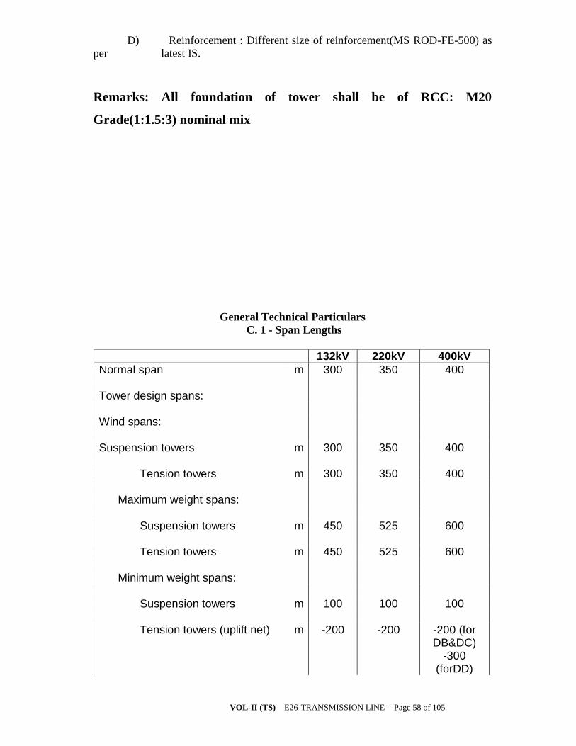
VOL-II (TS) E26-TRANSMISSION LINE- Page 58 of 105
D) Reinforcement : Different size of reinforcement(MS ROD-FE-500) as
per latest IS.
Remarks: All foundation of tower shall be of RCC: M20
Grade(1:1.5:3) nominal mix
General Technical Particulars
C. 1 - Span Lengths
132kV 220kV 400kV
Normal span m 300 350 400 Tower design spans: Wind spans: Suspension towers m 300 350 400 Tension towers m 300 350 400 Maximum weight spans: Suspension towers m 450 525 600 Tension towers m 450 525 600 Minimum weight spans: Suspension towers m 100 100 100 Tension towers (uplift net) m -200 -200 -200 (for
DB&DC) -300
(forDD)

VOL-II (TS) E26-TRANSMISSION LINE- Page 59 of 105

VOL-II (TS) E26-TRANSMISSION LINE- Page 60 of 105
C . 2 - Line Conductor ( 132 kV Construction )
Complete line conductor: Actual area (total) per single conductor mm2 288.3 Number of conductors per phase ONE Horizontal distance between conductor centres of one phase
mm -
Each single conductor: Equivalent to ACSR conductor of code name ACSR
PANTHER IEC STANDARD No IEC 1089 INDIAN STANDARD No IS 398 (Pt
4) 1994 Material of conductor AlumIminiu
m Number and diameter of wires: Aluminium No./mm 30/3.0 Total area of conductor mm2 261.5 Overall diameter of stranded conductor mm 21 Mass of conductor per kilometre kg 974 Ultimate strength of conductor Newton 89670 Assumed equivalent modulus of elasticity of conductor
N/mm2 81580
Assumed equivalent coefficient of linear expansion of conductor
per C 17.8x 10⁻⁶
Maximum length of conductor supplied on one drum
km 2.4+/-5%

VOL-II (TS) E26-TRANSMISSION LINE- Page 61 of 105
C . 3 - Line Conductor ( 220 kV Construction )
Complete line conductor: Actual area (total) per single conductor mm2 484.5 Number of conductors per phase ONE Horizontal distance between conductor centres of one phase
mm -
Each single conductor: Equivalent to ACSR conductor of code name ACSR ZEBRA IEC STANDARD No IEC 1089 INDIAN STANDARD No IS 398 (Pt 4) 1994 Material of conductor Aluminium Number and diameter of wires: Aluminium No./m
m 54/3.18
Total area of conductor mm2 428.9 Overall diameter of stranded conductor mm 28.62 Mass of conductor per kilometre kg 1621 Ultimate strength of conductor Newto
n 130320
Assumed equivalent modulus of elasticity of conductor
N/mm2 81580
Assumed equivalent coefficient of linear expansion of conductor
per C 19.3 x 10⁻⁶
Maximum length of conductor supplied on one drum
km 1.8 +/- 5%
C . 4 - Line Conductor ( 400 kV Construction )
Complete line conductor: Actual area (total) per single conductor mm2 597.00 Number of conductors per phase TWO
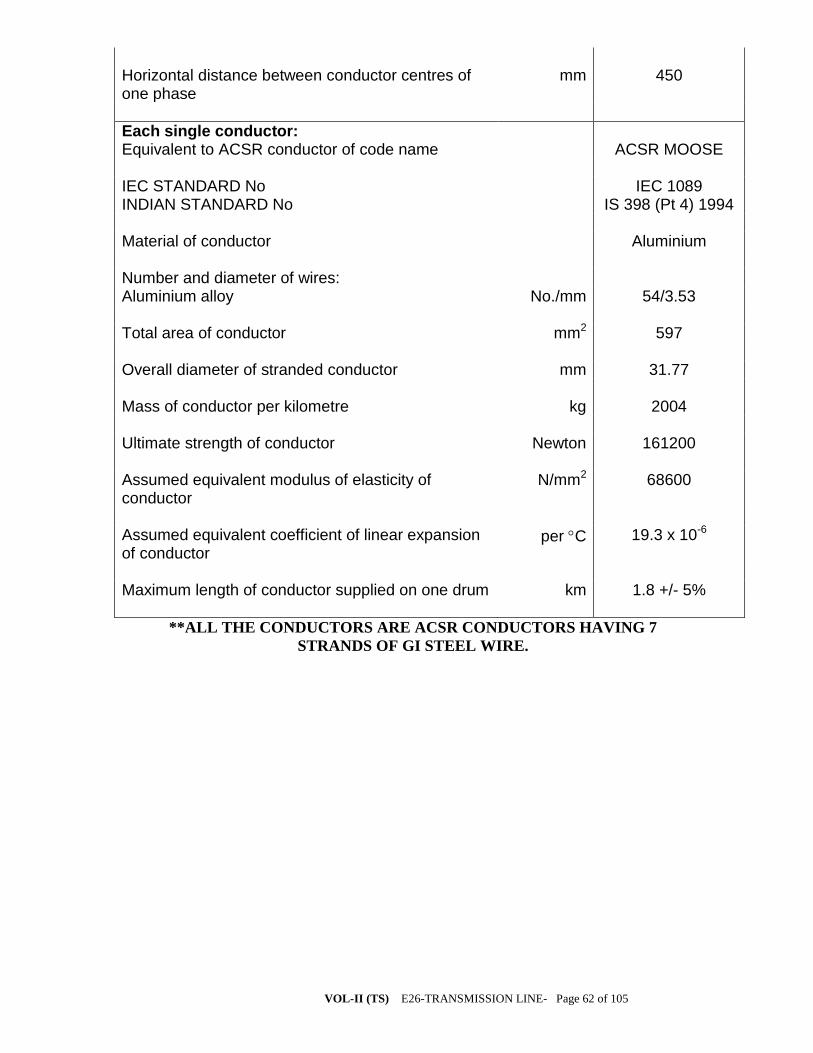
VOL-II (TS) E26-TRANSMISSION LINE- Page 62 of 105
Horizontal distance between conductor centres of one phase
mm 450
Each single conductor: Equivalent to ACSR conductor of code name ACSR MOOSE IEC STANDARD No IEC 1089 INDIAN STANDARD No IS 398 (Pt 4) 1994 Material of conductor Aluminium Number and diameter of wires: Aluminium alloy No./mm 54/3.53 Total area of conductor mm2 597 Overall diameter of stranded conductor mm 31.77 Mass of conductor per kilometre kg 2004 Ultimate strength of conductor Newton 161200 Assumed equivalent modulus of elasticity of conductor
N/mm2 68600
Assumed equivalent coefficient of linear expansion of conductor
per C 19.3 x 10⁻⁶
Maximum length of conductor supplied on one drum km 1.8 +/- 5%
**ALL THE CONDUCTORS ARE ACSR CONDUCTORS HAVING 7
STRANDS OF GI STEEL WIRE.

VOL-II (TS) E26-TRANSMISSION LINE- Page 63 of 105
C . 5 - Earth Wire (132 kV And 220 kV Constructions)
GSW
Complete earth conductor: Appropriate Indian Standard No 398(Part-2) Appropriate British Standard No 183 Material of conductor galvanised steel Number and diameter of wires No./m
m 7/3.15
Overall diameter of conductor mm 9.45 Mass of conductor per kilometre kg 428 Ultimate strength of conductor Newto
n 56000
Lay length mm 160 +/- 15 Direction of the lay of the outer layer Right hand Chemical composition of the steel wire % Carbon not more than 0.55 Manganese 0.4 to 0.9 Phosphorous not more than 0.04 Sulphur not more than 0.04 Silicon 0.15 to 0.35 Purity of Zinc for galvanising % 99.95 Galvanising after stranding a) Minimum weight of Zinc coating per sq. m. of the uncoated wire surface
gms 240
b) Minimum no. of one minute dips that the galvanised wire can withstand in Standard Preece Test
3 and 1/2
Maximum length of conductor on drum # km 4 +/- 5% D.C. resistance at 20 o C ohms/k
m 3.375
C . 6 - Earth Wire (400 kV Construction )
GSW
Complete earth conductor:
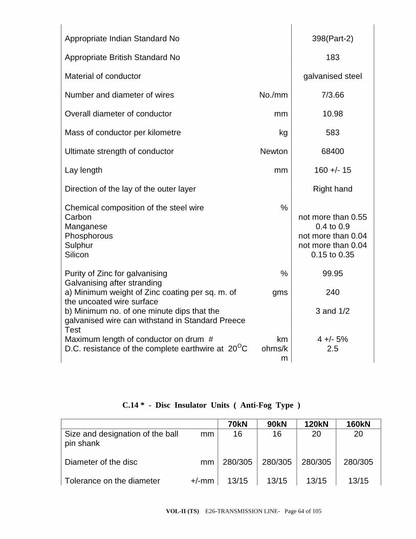
VOL-II (TS) E26-TRANSMISSION LINE- Page 64 of 105
Appropriate Indian Standard No 398(Part-2) Appropriate British Standard No 183 Material of conductor galvanised steel Number and diameter of wires No./mm 7/3.66 Overall diameter of conductor mm 10.98 Mass of conductor per kilometre kg 583 Ultimate strength of conductor Newton 68400 Lay length mm 160 +/- 15 Direction of the lay of the outer layer Right hand Chemical composition of the steel wire % Carbon not more than 0.55 Manganese 0.4 to 0.9 Phosphorous not more than 0.04 Sulphur not more than 0.04 Silicon 0.15 to 0.35 Purity of Zinc for galvanising % 99.95 Galvanising after stranding a) Minimum weight of Zinc coating per sq. m. of the uncoated wire surface
gms 240
b) Minimum no. of one minute dips that the galvanised wire can withstand in Standard Preece Test
3 and 1/2
Maximum length of conductor on drum # km 4 +/- 5% D.C. resistance of the complete earthwire at 20OC ohms/k
m 2.5
C.14 * - Disc Insulator Units ( Anti-Fog Type )
70kN 90kN 120kN 160kN
Size and designation of the ball pin shank
mm 16 16 20 20
Diameter of the disc mm 280/305 280/305 280/305 280/305 Tolerance on the diameter +/-mm 13/15 13/15 13/15 13/15

VOL-II (TS) E26-TRANSMISSION LINE- Page 65 of 105
Ball to ball spacing between disc
mm 145 145 145 170
Tolerance on ball to ball spacing
+/-mm 4 4 4 5
Minimum creepage distance of a single disc **
mm 430 430 430 475
Steepness of the impulse voltage which the disc unit can withstand in Steep Wave Front Test
kV per micro
sec.
2500 2500 2500 2500
Purity of Zinc used for galvanising
% 99.95 99.95 99.95 99.95
Purity of Zinc used for sleeve % 99.7 99.7 99.7 99.7 No. of dips in Standard Preece Test 1) Cap socket 2) Ball pin
6 6
6 6
6 6
6 6
*The parameters specified are for disc insulator unit only. For the Bids offering
composite insulator units, the parameters may be suitably selected by the Bidder
so as to meet the overall requirements of the respective strings and same shall be
guaranteed at Schedules 13A and 14A of the Technical Data Requirement
Schedules, Section X.
** The minimum creepage distance of single composite insulator unit shall be such
that it matches with the total creepage distance of the respective strings with disc
insulator units.
C . 15 - Insulator Strings (Suspension Sets For 132 kV Lines )
Single “I” Suspensio
n Strings
Double “I” Suspensio
n Strings
Pilot Suspension
Strings
Power frequency withstand voltage of the string with arcing horns and corona control rings / grading rings under wet conditions
kV(rms) 275 275 275
Impulse withstand voltage

VOL-II (TS) E26-TRANSMISSION LINE- Page 66 of 105
(peak) under dry conditions 1) Positive Kv 650 650 650 2) Negative kV 650 650 650 Minimum corona extinction voltage under dry conditions
kV(rms) 105 105 105
Radio interference voltage under dry conditions at 1MHz, at 105kV
Micro Volts
not more than 1000
not more than 1000
not more than 1000
Mechanical strength of the complete insulator string along with all hardware fittings
kN 70 2x70 70
Maximum voltage (in percentage) across any disc in the complete insulator string under phase to earth voltage *
% 20 20 20
Number of insulator units in each string **
9 2x9 9
Purity of Zinc used for galvanising
% 99.95 99.95 99.95
Minimum No. of one minute dips the ferrous parts can withstand in Standard Preece Test
No. 6 6 6
* Voltage distribution criteria is not applicable for strings with composite
insulator units.
** It is preferrable to have single piece composite insulator unit for each limb of
the string. In case, more than one units are used per limb, same shall be indicated
by the Contractor.
C . 16 - Insulator Strings ( Tension Sets For 132 kV Lines )
Single Tension Strings
Double Tension Strings
Power frequency withstand voltage of the string with arcing horns and corona control rings / grading rings under wet
kV(rms) 275 275

VOL-II (TS) E26-TRANSMISSION LINE- Page 67 of 105
conditions Impulse withstand voltage (peak) under dry conditions
1) Positive kV 650 650 2) Negative kV 650 650 Minimum corona extinction voltage under dry conditions
kV(rms) 105 105
Radio interference voltage under dry conditions at 1MHz, at 105kV
Micro Volts
not more than 1000
not more than 1000
Mechanical strength of the complete insulator string along with all hardware fittings
kN 90 2x90
Maximum voltage (in percentage ) across any disc in the complete insulator string under phase to earth voltage *
% 22 22
Number of insulator units in each string **
10 2x10
Purity of Zinc used for galvanising
% 99.95 99.95
Minimum No. of one minute dips the ferrous parts can withstand in Standard Preece Test
No. 6 6
* Voltage distribution criteria is not applicable for strings with composite
insulator units.
** It is preferrable to have single piece composite insulator unit for each limb of
the string. In case, more than one units are used per limb, same shall be indicated
by the Contractor.
C . 17 - Insulator Strings (Suspension Sets For 220 kV Lines )
Single “I” Suspensi
on Strings
Double “I”
Suspension
Strings
Pilot Suspensio
n Strings
Power frequency withstand voltage of the string with
kV(rms) 460 460 460

VOL-II (TS) E26-TRANSMISSION LINE- Page 68 of 105
arcing horns and corona control rings / grading rings under wet conditions Impulse withstand voltage (peak) under dry conditions
1) Positive kV 1050 1050 1050 2) Negative kV 1050 1050 1050 Minimum corona extinction voltage under dry conditions
kV(rms) 154 154 154
Radio interference voltage under dry conditions at 1MHz, at 154kV
Micro Volts
not more than 1000
not more than 1000
not more than 1000
Mechanical strength of the complete insulator string along with all hardware fittings
kN 70 2x70 70
Maximum voltage (in percentage ) across any disc in the complete insulator string under phase to earth voltage *
% 13 13 13
Number of insulator units in each string**
14 2x14 14
Purity of Zinc used for galvanising
% 99.95 99.95 99.95
Minimum No. of one minute dips the ferrous parts can withstand in Standard Preece Test
No. 6 6 6
* Voltage distribution criteria is not applicable for strings with composite
insulator units.
** It is preferrable to have single piece composite insulator unit for each limb of
the string. In case, more than one units are used per limb, same shall be indicated
by the Contractor.
C . 18 - Insulator Strings ( Tension Sets For 220 kV Lines )
Single Tension Strings
Double Tension Strings

VOL-II (TS) E26-TRANSMISSION LINE- Page 69 of 105
Power frequency withstand voltage of the string with arcing horns and corona control rings / grading rings under wet conditions
kV(rms) 460 460
Impulse withstand voltage (peak) under dry conditions
1) Positive kV 1050 1050 2) Negative kV 1050 1050 Minimum corona extinction voltage under dry conditions
kV(rms) 154 154
Radio interference voltage under dry conditions at 1MHz, at 105kV
Micro Volts
not more than 1000
not more than 1000
Mechanical strength of the complete insulator string along with all hardware fittings
kN 120 2x120
Maximum voltage (in percentage ) across any disc in the complete insulator string under phase to earth voltage *
% 14 14
Number of insulator units in each string **
15 2x15
Purity of Zinc used for galvanising % 99.95 99.95 Minimum No. of one minute dips the ferrous parts can withstand in Standard Preece Test
No. 6 6
* Voltage distribution criteria is not applicable for strings with composite
insulator units.
** It is preferrable to have single piece composite insulator unit for each limb of
the string. In case, more than one units are used per limb, same shall be indicated
by the Contractor.
C . 19 - Insulator Strings (Suspension Sets For 400 kV Lines )
Single “I” Suspensio
n Strings
Pilot Suspension
Strings
Power frequency withstand voltage of the string with arcing horns and
kV(rms) 680 680

VOL-II (TS) E26-TRANSMISSION LINE- Page 70 of 105
corona control rings / grading rings under wet conditions Switching surge withstand voltage (peak) under wet conditions
1) Positive kV 1050 1050 2) Negative kV 1050 1050 Impulse withstand voltage (peak) under dry conditions
1) Positive kV 1550 1550 2) Negative kV 1550 1550 Minimum corona extinction voltage under dry conditions
kV(rms) 320 320
Radio interference voltage under dry conditions at 1MHz, at 305kV
Micro Volts
not more than 1000
not more than 1000
Mechanical strength of the complete insulator string along with all hardware fittings
kN 120 120
Maximum voltage (in percentage ) across any disc in the complete insulator string under phase to earth voltage *
% 9 9
Number of insulator units in each string **
23 23
Purity of Zinc used for galvanising % 99.95 99.95 Minimum No. of one minute dips the ferrous parts can withstand in Standard Preece Test
No. 6 6
* Voltage distribution criteria is not applicable for strings with composite
insulator units.
** It is preferrable to have single piece composite insulator unit for each limb of
the string. In case, more than one units are used per limb, same shall be indicated
by the Contractor.
C . 20 - Insulator Strings ( Tension Sets For 400 kV Lines )
SingleTension
Strings (Low Duty)
Double Tension Strings
Power frequency withstand voltage kV(rms) 680 680

VOL-II (TS) E26-TRANSMISSION LINE- Page 71 of 105
of the string with arcing horns and corona control rings / grading rings under wet conditions Switching surge withstand voltage (peak) under wet conditions
1) Positive kV 1050 1050 2) Negative kV 1050 1050 Impulse withstand voltage (peak) under dry conditions
1) Positive kV 1550 1550 2) Negative kV 1550 1550 Minimum corona extinction voltage under dry conditions
kV(rms) 320 320
Radio interference voltage under dry conditions at 1MHz, at 305kV
Micro Volts
not more than 1000
not more than 1000
Mechanical strength of the complete insulator string along with all hardware fittings
kN 120 2x160
Maximum voltage (in percentage ) across any disc in the complete insulator string under phase to earth voltage *
% 10 10
Number of insulator units in each string **
24 2x23
Purity of Zinc used for galvanising % 99.95 99.95 Minimum No. of one minute dips the ferrous parts can withstand in Standard Preece Test
No. 6 6
* Voltage distribution criteria is not applicable for strings with composite
insulator units.
** It is preferrable to have single piece composite insulator unit for each limb of
the string. In case, more than one units are used per limb, same shall be indicated
by the Contractor.
C . 21 - Tower Design Particulars (132 kV Construction)
Minimum clearance between live metal and tower steelwork:

VOL-II (TS) E26-TRANSMISSION LINE- Page 72 of 105
i.with suspension insulator set swing 0° mm 1530 with suspension insulator set swing 15° mm 1530 with suspension insulator set swing 30° mm 1370 with suspension insulator set swing 45° mm 1220 with suspension insulator set swing 60° mm 1070 ii.with jumper loop swing 0° mm 1530 with jumper loop swing 10° mm 1530 with jumper loop swing 20° mm 1070 with jumper loop swing 30° mm 1070 with jumper loop swing 40° mm - Insulator suspension set, unobstructed transverse swing angle
from vertical degrees 0 - 60 Earth conductor suspension clamps, unobstructed transverse
swing angle from vertical degrees 0 - 50 Earth conductor maximum shielding angle from vertical at
tower attachment point over outer line conductors
degrees 30
C . 22 - Tower Design Particulars (220 kV Construction)
Minimum clearance between live metal and tower steelwork:
i. with suspension insulator set swing 0° mm 2130 with suspension insulator set swing 15° mm 1980 with suspension insulator set swing 30° mm 1830 with suspension insulator set swing 45° mm 1675 with suspension insulator set swing 60° mm - ii. with jumper loop swing 0° mm 2130

VOL-II (TS) E26-TRANSMISSION LINE- Page 73 of 105
with jumper loop swing 10° mm 1675 with jumper loop swing 20° mm 1675 with jumper loop swing 30° mm - with jumper loop swing 40° mm - Insulator suspension set, unobstructed transverse swing angle
from vertical degrees 0 - 45 Earth conductor suspension clamps, unobstructed transverse
swing angle from vertical degrees 0 - 50 Earth conductor maximum shielding angle from vertical at
tower attachment point over outer line conductors
degrees 30

VOL-II (TS) E26-TRANSMISSION LINE- Page 74 of 105
C . 23 - Tower Design Particulars (400 kV Construction)
Minimum clearance between live metal and tower steelwork:
i. with suspension insulator set swing 0° mm 3050 with suspension insulator set swing 15° mm 3050 with suspension insulator set swing 30° mm 1860 with suspension insulator set swing 45° mm - with suspension insulator set swing 60° mm - ii. with jumper loop swing 0° mm 3050 with jumper loop swing 10° mm 3050 with jumper loop swing 20° mm 3050 with jumper loop swing 30° mm 1860 with jumper loop swing 40° mm 1860 Insulator suspension set, unobstructed transverse swing angle
from vertical degrees 0 - 30 Earth conductor suspension clamps, unobstructed transverse
swing angle from vertical degrees 0 - 50 Earth conductor maximum shielding angle from vertical at
tower attachment point over outer line conductors degrees 20

VOL-II (TS) E26-TRANSMISSION LINE- Page 75 of 105
C . 25 - Particulars Of Double Circuit Towers (132 kV Construction )
Type Of Tower DA DB DC DD
Type of insulator sets Suspension
Tension Tension
Tension
Maximum angle of deviation
degree 0 - 2 0 - 15 15 - 30
30 - 60
Normal span length m 300 300 300 300 Minimum ground clearance of line
conductor at 85°C, normal ground
m 6.42 6.42 6.42 6.42
Minimum height of earth conductors above
upper line conductor at mid-span
m 6.1 6.1 6.1 6.1
Vertical spacing between line conductors
at tower (minimum) m 3.9 3.9 3.9 3.9 Minimum Clearance between conductors of one circuit and tower climbing leg of the other circuit.
m 4.5 4.5 4.5 4.5
C . 26 - Particulars Of Double Circuit Towers (220 kV Construction )
Type Of Tower DA DB DC DD
Type of insulator sets Suspension
Tension Tension
Tension
Maximum angle of deviation
degree 0 - 2 0 - 15 15 - 30 30 - 60

VOL-II (TS) E26-TRANSMISSION LINE- Page 76 of 105
Normal span length m 350 350 350 350 Minimum ground clearance of line
conductor at 85 °C, normal ground
m 7.23 7.23 7.23 7.23
Minimum height of earth conductors above
upper line conductor at mid-span
m 8.5 8.5 8.5 8.5
Vertical spacing between line conductors
at tower (minimum) m 4.9 4.9 4.9 4.9 Minimum Clearance between conductors of one circuit and tower climbing leg of the other circuit.
m 5.5 5.5 5.5 5.5
C . 27 - Particulars Of Double Circuit Towers ( 400 kV Construction )
Type Of Tower DA DB DC DD
Type of insulator sets Suspension
Tension Tension Tension
Maximum angle of deviation
degree 0 - 2 0 - 15 15 - 30 30 - 60
Normal span length m 400 400 400 400 Minimum ground clearance of line
conductor at 85 °C, normal ground
m 8.84 8.84 8.84 8.84
Minimum height of earth conductors above
upper line conductor m 9.0 9.0 9.0 9.0

VOL-II (TS) E26-TRANSMISSION LINE- Page 77 of 105
at mid-span Vertical spacing between line conductors
at tower (minimum ) . m 8.0 8.0 8.0 8.0 Minimum Clearance between conductors of one circuit and tower climbing leg of the other circuit.
m 6.5 6.5 6.5 6.5
C . 28 - Foundation Design Particulars
Assumed density of Plain Cement Concrete (PCC) for foundation in dry soil
kg/m3 2240
Assumed density of Plain Cement Concrete (PCC) for foundation in presence of sub-soil water
kg/m3 1240
Assumed density of Re-inforced Cement Concrete (RCC) for foundation in dry soil
kg/m3 2400
Assumed density of Re-inforced Cement Concrete (RCC) for foundation in presence of sub-soil water
kg/m3 1400
28 day concrete cube strength (characteristic strength for M-20 concrete)
N/mm2 20
28 day concrete cube strength (characteristic strength for M-15 concrete)
N/mm2 15
Minimum proportion of stub load to be allowed for in the design of stub cleats
% 100
Density of all type of soils : 1) under dry conditions kg/m3 1440 2) in presence of surface water kg/m3 1440 3) in presence of sub-soil water kg/m3 840 Ultimate bearing capacity of the soil : 1) normal soil under dry condition kN/m2 214 2) normal soil in presence of surface as well as kN/m2 107

VOL-II (TS) E26-TRANSMISSION LINE- Page 78 of 105
sub-soil water 3) wet black cotton soil kN/m2 107 4) fissured rock ( both for dry and wet ) kN/m2 400 5) hard rock kN/m2 750 Angle of repose for : 1) dry soil Degree 30 2) wet soil due to presence of surface/ sub-soil water
Degree 15
3) wet black cotton soil Degree 0 4) dry fissured rock Degree 20 5) wet fissured rock Degree 10 Ultimate bond between steel and concrete kN/m2 0.147
Note : All the soil parameters furnished above are subject to verification by actual soil
investigations. The Contractor shall be required to carry-out field test for each type of
foundation, as per the quoted rates in Price Schedules, to prove the design parameters
considered.
The foundation classification criteria shall be as given below, depending upon type of
soil and sub-soil water level / presence of surface water :
Normal Dry : To be used for locations where normal dry cohesive or non-cohesive soils
are met without encountering sub-soil water table within the depth of foundation.
Wet : To be used for locations,
a) where sub-soil water is met at 1.5 m. or more below the ground level;
b) which are in surface water for long periods with water penetration not
exceeding one metre below the ground level e.g. , the paddy field.
Partially Submerged : To be used for the locations where sub-soil water table is met
between 0.75 to 1.5 m. below the ground level;
Fully Submerged : To be used for locations where sub-soil water table is met at less
than 0.75 m. below the ground level;
Black Cotton Type : To be used at locations where soil is clayey type, not necessarily
black in colour, which shrinks when dry and swells when wet, resulting in differential
movement. For designing the foundation for such locations, the soil is to be considered
as fully submerged.
Fissured Rock : To be used at locations where decomposed or fissured rock, hard
gravel, kankar, lime-stone, laterite or any other soil of similar nature is met. Under-cut
type foundation is to be used for such locations.
In case of fissured rock locations where water table is met at 1.5 m. or more below
ground level, wet type fissured rock foundations shall be adopted.
Hard Rock : To be used for the locations where chiselling, drilling or blasting is
required for excavation . For these locations rock anchoring is to be provided to resist
the uplift forces.

VOL-II (TS) E26-TRANSMISSION LINE- Page 79 of 105
PILE FOUNDATION-
a) SCOPE- The work involved is to take up the pile foundation work of
including stub setting of special type tower. The detailed survey, soil investigation and
the design has to be done bidder and the design is to be approved by OPTCL, which
shall be strictly followed by the contractor. The contractor shall cast the foundation
including stub setting as per the design, the schedule of quantities enclosed and
direction of engineer in charge.
b) 1. The pile foundation shall be of RCC, Cast-in-situ bored piles as per IS:2911 . Pile
boring shall be done using Rotary Hydraulic Rigs. Two stage flushing of pile bore shall
be ensured by airlift technique duly approved by the Employer
2. Minimum diameters of piles shall be 450/500mm (for under reamed piles)/
600 mm (for bored cast in situ piles).
3. Only straight shaft piles shall be used. Minimum cast length of pile above cutoff
level shall be 1.0 m.
4. The bidder shall furnish design of piles (in terms of rated capacity, length,
diameter, termination criteria to locate the founding level for construction of pile in
terms of measurable parameter, reinforcement for job as well as test piles, locations of
initial test piles etc.) for Engineer’s approval.
5. The piling work shall be carried out in accordance with IS:2911 (Relevant part)
and accepted construction methodology. The construction methodology shall be
submitted by the Contractor for Engineer's approval.
6. Number of initial load tests to be performed for each diameter and rated capacity of pile
shall be subject to minimum as under.
Vertical
Lateral : Minimum of 2 Nos. in each mode
Uplift
7. The initial pile load test shall be conducted with test load upto three times the estimated
pile capacity. In case of compression test (initial test) the method of loading shall be
cyclic as per IS:2911 (relevant part).
8. Load test shall be conducted at pile cut of level (COL). If the water table is above the
COL the test pit shall be kept dry through out the test period by suitable de-watering
methods. Alternatively the vertical load test may be conducted at a level higher than
COL. In such a case, an annular space shall be created to remove the effect of skin
friction above COL by providing an outer casing of suitable diameter larger than the
pile diameter

VOL-II (TS) E26-TRANSMISSION LINE- Page 80 of 105
9. Number of routine pile load tests to be performed for each diameter/allowable capacity
of pile shall be as under :
(i) Vertical : 0.5% of the total number of piles provided.
(ii) Lateral : 0.5% of the total number of piles provided.
10. The routine tests on piles shall be conducted upto test load of one and half times the
allowable pile capacity. Piles for routine load tests shall be approved by the Employer.
11. In case, routine pile load test shows that the pile has not achieved the desired capacity
or pile(s) have been rejected due to any other reason, then the Contractor shall install
additional pile(s) as required and the pile cap design shall accordingly be reviewed and
modified, if required.
12. Testing of piles and interpretation of pile load test results shall be carried out as per
IS:2911 (Part-4). Contractor shall ensure that all the measuring equipment and
instruments are properly calibrated at a reputed laboratory / institute prior to their use.
Settlement / movement of the pile top shall be made by Linear Variable Differential
Transducers (LVDT) having a least count of 0.01mm.
13. The test load on initial test piles shall be applied by means of reaction from
anchor piles / rock anchors alone or combination of anchor piles / rock anchors and
kentledge.
14. Low Strain Pile Integrity test shall be conducted on all test piles and job piles.
This test shall be used to identify the routine load test and not intended to replace the
use of static load test. This test is limited to assess the imperfection of the pile shaft
and shall be undertaken by an independent specialist agency. The test equipment shall
be of TNO or PDI make or equivalent. The process shall confirm to ASTM.
15. Contribution of frictional resistance of filled up soil if any, shall not be considered
for computation of frictional resistance of piles.
16. The following shall be adhered to PILE FOUNDATION:
i) The pile foundation shall be of under reamed piles as per IS: 2911 part III or
bored cast in situ piles as per IS 2911 part I sec2
ii) The minimum diameter of pile shall be 500 mm in case of under reamed piles
and 600 mm in case of bored cast in situ piles.
iii) Under reamed piles shall be adopted only in case of clay black cotton soil or
medium dense sandy soil is encountered. Design of under reamed shall be done
strictly as per IS 2911 part III.
iv) The bidder shall furnish design of piles (in terms of rated capacity, length,
diameter, termination criteria to locate the founding level for construction of pile in
terms of measurable parameter, reinforcement for job as well as test piles, locations
of initial test piles etc.) for Engineer’s approval.
v) The piling work shall be carried out in accordance with IS:2911 (Relevant part)
and accepted construction methodology. The construction methodology shall be
submitted by the Contractor for Engineer's approval.

VOL-II (TS) E26-TRANSMISSION LINE- Page 81 of 105
vi) Number of initial load tests to be performed for each diameter and rated
capacity of pile shall be subject to minimum as under.
Vertical
Lateral Minimum of 2 Nos. in each mode.
Uplift
vii) The initial pile load test shall be conducted with test load upto three times the
estimated pile capacity. In case of compression test (initial test) the method of
loading shall be cyclic as per IS:2911 (part IV).
viii) Load test shall be conducted at pile cut of level (COL). If the water table is
above the COL the test pit shall be kept dry through out the test period by suitable
de-watering methods. Alternatively the vertical load test may be conducted at a
level higher than COL. In such a case, an annular space shall be created to remove
the effect of skin friction above COL by providing an outer casing of suitable
diameter larger than the pile diameter.
ix) Number of routine pile load tests to be performed for each diameter/allowable
capacity of pile shall be as under :
i) Vertical : 0.5% of the total number of piles provided.
ii) Lateral : 0.5% of the total number of piles provided.
x) The routine tests on piles shall be conducted upto test load of one and half times
the allowable pile capacity. Piles for routine load tests shall be approved by the
Employer.
xi) In case, routine pile load test shows that the pile has not achieved the desired
capacity or pile(s) have been rejected due to any other reason, then the Contractor
shall install additional pile(s) as required and the pile cap design shall accordingly be
reviewed and modified, if required.
xii) Testing of piles and interpretation of pile load test results shall be carried out as
per IS:2911 (Part-4). Contractor shall ensure that all the measuring equipment and
instruments are properly calibrated at a reputed laboratory / institute prior to their
use. Settlement / movement of the pile top shall be made by Linear Variable
Differential Transducers (LVDT) having a least count of 0.01mm.
xiii) The test load on initial test piles shall be applied by means of reaction from
anchor piles / rock anchors alone or combination of anchor piles / rock anchors and
kentledge.
xiv) Contribution of frictional resistance of filled up soil if any, shall not be
considered for computation of frictional resistance of piles.

VOL-II (TS) E26-TRANSMISSION LINE- Page 82 of 105
a) MATERIALS- Contractor shall supply cement, steel rod and stubs and
all other materials required. All coarse aggregates, fine aggregates are to be of very
good quality and to be approved by the engineer in charge.
b) Watch and Ward- The cost of watch and ward, site store, making of
Islanding/platform for the pile boring, stabilization of bore hole and all other activities
incidental to successful construction of the pile foundation are to be included in the
cost of the tender and no additional cost shall be paid separately on any additional
component.
The cement, steel shall be supplied to the contractor at the nearest tore and the
contractor shall have to receive the same at designated stores and transport to site at
his own cost.
The piling shall be done in presence of the engineer in charge and due certification to
be done at the spot only.
Standard followed and to be followed-
Indian Title International and
Standards(IS) Internationally
Recognize
Standard/Code
IS:1080-1990 Codes of Practice
for Design and
Construction of
Simple Spread
Foundations
IS: 1498-1992 Classification and ASTM D 2487/
Identification of ASTM D 2488
Soils for General
Engineering
Purposes.
IS: 1892-1992 Code of Practice
For Design and
Construction of
Foundation in
Soils : General
Requirements.
IS: 2131-1992 Method of Standard ASTM D 1586
Penetration Soils

VOL-II (TS) E26-TRANSMISSION LINE- Page 83 of 105
IS: 2132-1992 Code of Practice ASTM D 1587
For Thin Walled
Sampling of Soils
IS: 2720-1992 Method of Test ASTM D 420
For Soils (Rele-
vant Parts.
IS: 2809-1991 Glossary of Terms ASTM D 653
And symbols
Relating to Soil
Engineering
Indian Title International and
Standards(IS) Internationally
Recognize
Standard/Code
IS: 2911-1980 Code of Practice
For Design and
Construction of
Pile Foundations
(Relevant Parts).
IS: 3025 Methods of Sampling
And Testing (Physical
And Chemical) for
Water used in industry.
IS: 3043-1991 Code or Practice for
Indexing and Storage
Of Drill Cores.
IS: 4091-1987 Code of Practice for
Design and Construction
Of Foundations for
Transmission Line Towers
and Poles.
IS: 4434-1992 Code of Practice for ASTM D 2573/
in-situ Vane Shear ASTM D 4648
Test for Soils.
IS: 4453-1992 Code of Practice for
Exploration by Pits,
Trenches, Drifts and
Shafts.
IS: 4464-1990 Code of Practice for
Presentation of Drilling
Information and core
Description in Foundation

VOL-II (TS) E26-TRANSMISSION LINE- Page 84 of 105
Investigation
IS: 4968 - Method for Subsurface
(Part-II) – 1992 sounding for soils,
dynamic method using
cone and Bentonite slurry
IS: 5313-1989 Guide for Core Drilling
Observations.
Indian Title International and
Standards(IS) Internationally
Recognize
Standard/Code
IS:6403-1990 Code of Practice for
Diamond Core Drilling
for Site Investigation
for River Valley Projects.
IS: 6935-1989 Method of Determination
of water level in a Bore
Hole.
IS: 7422-1990 Symbols and Abbreviations
for use in Geological Maps
Sections and subsurface
Exploratory Logs (Relevant
Parts).
IS:8009 Code of Practice for
(Part-I)-1993 Calculation of Settlements
of Foundations (Shallow
Foundations subjected
to symmetrical Vertical
Loads).
IS:8764-1991 Method of Determination
of Point Load Strength
Index of Rocks.
IS: 9179-1991 Method of Determination ASTM D 2938
of Unconfined compressive
Strength of Rock Materials.
IS: 9179-1991 Method of Preparation ASTM D 4543
of Rock Specimen for
Laboratory Testing.
IS: 9259-1992 Specification for Liquid ASTM D 4318
Limit apparatus.
IS: 9640-1992 Specification for Split ASTM D 1586

VOL-II (TS) E26-TRANSMISSION LINE- Page 85 of 105
Spoon Sampler
IS: 10050-1992 Method of Determination ASTM D 4644
of Slake Durability Index
of Rocks.
IS: 11315- Description of Discontinuities
(Part-II)-1991 in Rock Mass-Core Recovery
TESTS Tests as indicated in this specification and as may be requested by the
Owner, shall be conducted. There tests shall include but may not be
limited to the following :
a) Tests of undisturbed and disturbed samples
- Visual and engineering classification;
- Sleeve analysis and hydrometric analysis;
- Liquid, plastic and shrinkage limits;
- Specific gravity;
- Chemical analysis
- Swell pressure and free swell index determination
- Proctor compaction test.
b) Tests of undisturbed samples:
- Bulk density and moisture content;
- Relative density (for sand),
- Unconfined compression test;
- Box shear test (for sand);
- Tri-axial shear tests (depending on the type of soil and field conditions on
undisturbed or remoulded samples):
i) Unconsolidated untrained;
ii) Consolidated drained test;
- Consolidation.
c) Tests on rock samples
- Visual classification:
- Moisture content, porosity and density:
- Specific gravity;
- Hardness
- Stake durability;
- Unconfined compression test (both saturated and at in-situ water content;
- Point load strength index;
- Deformability test (both saturated and dry samples)

VOL-II-Technical Specification for Insulators- E33 Page 1
ODISHA POWER TRANSMISSION CORPORATION LIMITED
TECHNICAL SPECIFICATION
FOR
DISC / PORCELAIN LONG ROD INSULATORS FOR SUBSTATION AND
TRANSMISSION LINE WORKS

VOL-II-Technical Specification for Insulators- E33 Page 2
INSULATORS
TECHNICAL SPECIFICATION FOR DISC / PORCELAIN LONG ROD INSULATORS FOR SUBSTATION AND
TRANSMISSION LINE WORKS.
1.0 SCOPE.
1.1 This specification provides for design, manufacture, engineering, inspection and testing before dispatch,
packing and delivery FOR (destination) for Indian manufacturers of disc / porcelain long rod Insulators as
per technical requirements furnished in this specification.
These insulators are to be used in suspension and tension insulator strings for the suspension and
anchoring of the conductors on EHV transmission line towers.
1.2 Following are the list of documents constituting this package.
(i) Technical specification.
(ii) Technical data sheet.
(iii) Drawings of insulators
1.3 All the above volumes along with amendments there of shall be read and interpreted together. However, in
case of a contradiction between the “Technical Specification” and any other volume, the provisions of this
volume will prevail.
1.4 The insulators shall conform in all respects to high standards of engineering, design, workmanship and
latest revisions of relevant standards at the time of offer and purchaser shall have the power to reject any
work or material which in his judgment, is not in full accordance therewith.
2.0 STANDARDS:
2.1 Except as modified in this specification, the disc/porcelain long rod insulators shall conform to the following
Indian Standards, which also includes latest revisions and amendments if any. Equivalent International and
Internally recognized standards to which some of these standards generally correspond are also listed
below.
Sl. No. Indian Standard Title. International Standard.
1. IS: 206 Method for Chemical Analysis
of Slab Zinc.
2. IS: 209 Specification for Zinc. BS: 3436
3. IS: 731 Porcelain insulators for BS: 137(I&II);
overhead power lines with a IEC 60274 IEC 60383
normal voltage greater than
1000V
4. IS: 2071 Part-(I) Method of High Voltage Testing.

VOL-II-Technical Specification for Insulators- E33 Page 3
Part-(II)
Part-(III)
5. IS: 2121 Specification of Conductors
and Earth wire Accessories
(Part-I) for Overhead Power lines.
Armour Rods, Binding wires
and tapes for conductor.
6. IS: 2486 Specification for Insulator
fittings for overhead power
lines with a nominal voltage
greater than 1000V.
Part – I General Requirement and BS: 3288
Tests.
Part – II Dimensional Requirements. IEC: 60120
Part – III Locking devices. IEC: 60372
7. IS: 2629 Recommended practice for
Hot Dip Galvanisation for iron
and steel.
8. IS: 2633 Testing for Uniformity of
Coating of Zinc coated
articles.
9. IS: 3138 Hexagonal Bolts & Nuts. ISO/R 947 &
ISO/R 272
10. IS: 3188 Dimensions for Disc IEC: 60305
Insulators.
11. IS: 4218 Metric Screw Threads ISO/R 68-1969
R 26-1963,
R 262-1969 &
R965-1969
12. IS: 6745 Determination of weight of
zinc coating on zinc coated
iron and steel articles.
13. IS: 8263 Methods of RIV Test of HV IEC 60437 NEMA
insulators. Publication
No.107/1964 CISPR
14. IS: 8269 Methods for switching impulse IEC: 60506
Test on HV insulators.
15. Thermal mechanical IEC: 60575
performance test and
mechanical performance test
on string insulator units.
16 IEC Ceramic Long Rod Insulators IEC: 60433
2.2 The standards mentioned above are available from:
Reference. Abbreviation. Name & Address:
BS British Standards, British Standards

VOL-II-Technical Specification for Insulators- E33 Page 4
Institution, 101, Pentonvile Road, N-
19 ND,U
IEC / CISPR International Electro technical
commission Electro Technique
International. 1, Rue de verembe
Geneva SWITZERLAND.
IS Bureau of Indian Standards, Manak
Bhavan, 9 Bahadurshah Zafar
Marg, New Delhi-110001, ORISSA
ISO International Organisation for
Standardization. Danish Board of
Standardization Dansk
Standardizing Sraat Aurehoegvej-
12 DK-2900 Helleprup DENMARK.
NEMA National Electric Manufacturers
Association 1`55, East 44th. Street
New York, NY 10017 USA
3.0 PRINCIPAL PARAMETERS.
3.1 DETAILS OF DISC INSULATORS:
3.1.1 The Insulator strings shall consist of standard discs for use in three phases. 50 Hz effectively earthed 33/132/220 KV transmission system of OPTCL in a moderately polluted atmosphere. The discs shall be cap and pin, ball and socket type, radio interference and have characteristics as shown in Table-I and all ferrous parts shall be hot dip galvanized as per the latest edition of IS 2629. The zinc to be used for making sleeves shall be 99.95 % pure.
3.1.2 The size of disc insulator, minimum creepage distance the number to be used in different type of strings, their
electromechanical strength and mechanical strength of insulator string along with hardware shall be as follows:
PRINCIPAL PARAMETERS OF THE DISC INSULATORS:-
Sl. Type of Size of Minimum No. of Electro-
No. String. disc. creepage standard mechanical
Insulator distance of discs strength of
(mm) each disc 132 KV insulator string
(mm), /220 KV/400kV fittings (KN) 1. Single 255 x 145 320 1x9/1x14 /- 70 KN/90 KN
suspension Normal Disc
Insulator 2. Double -do- -do- 2x9/2x14 /- 70 KN/90 KN
suspension. Normal Disc
Insulator 3 Single 255 x 145 430 1x9/1x14 /- 70 KN/90 KN
suspension Antifog Insulator 4 Double -do- -do- 2x9/2x14 /- 70 KN/90 KN
suspension. Antifog Disc
Insulator

VOL-II-Technical Specification for Insulators- E33 Page 5
5. Single Suspension 280 x 145 430 1x10/1x15 /-
120 KN Anti fog Disc insulator
6.
Double
suspension 280 x 145 430 2x10/2x15 /- 120 KN Anti fog Disc insulator
7. Single Tension 305 X 170 475 1x10/1x15/1x25
160 KN Anti fog Disc insulator
8. Double Tension 305 X 170 475 2x10/2x15/2x25
160 KN Anti fog Disc insulator
9. Single Suspension 280 x 145 430 1x10/1x15/1x25
120 KN Anti fog Disc insulator
10.
Double
suspension 280 x 145 430 2x10/2x15/2x25 120 KN Anti fog Disc insulator
3.2 SPECIFICATION DRAWINGS:
3.2.1: The Specification in respect of the disc insulators are described, The specification is for
information and guidance of the bidder only. The drawings to be furnished by the supplier shall be
as per his own design and manufacture and in line with the specification.
4.0 GENERAL TECHNICAL REQUIREMENTS FOR DISC INSULATORS:
4.1 Porcelain:
The porcelain used in the manufacture of the shells shall be nonporous, of high dielectric, mechanical and
thermal strength, free from internal stresses blisters, laminations, voids, forgone matter imperfections or other
defects which might render it in any way unusable for insulator shells. Porcelain shall remain unaffected by
climatic conditions ozone, acid, alkalis, zinc or dust. The manufacturing shall be by the wet process and
impervious character obtained by through vitrification.
The insulator shall be made of highest grade, dense, homogeneous, wet-process porcelain, completely and
uniformly vitrified throughout to produce uniform mechanical and electrical strength and long life service. The
porcelain shall be free from warping, roughness, cracks, blisters, laminations, projecting points, foreign particles
and other defects, except those within the limits of standard accepted practice. Surfaces and grooves shall be
shaped for easy cleaning. Shells shall be substantially symmetrical.
4.1.1 Porcelain glaze:
The finished porcelain shall be glazed in brown colour. The glaze shall cover all exposed parts of the insulator
and shall have a good lusture, smooth surface and good performance under the extreme weather conditions of
a tropical climate. It shall not crack or chip by ageing under the normal service conditions. The glaze shall have
the same coefficient of expansion as of the porcelain body throughout the working temperature range.
4.2 METAL PARTS:
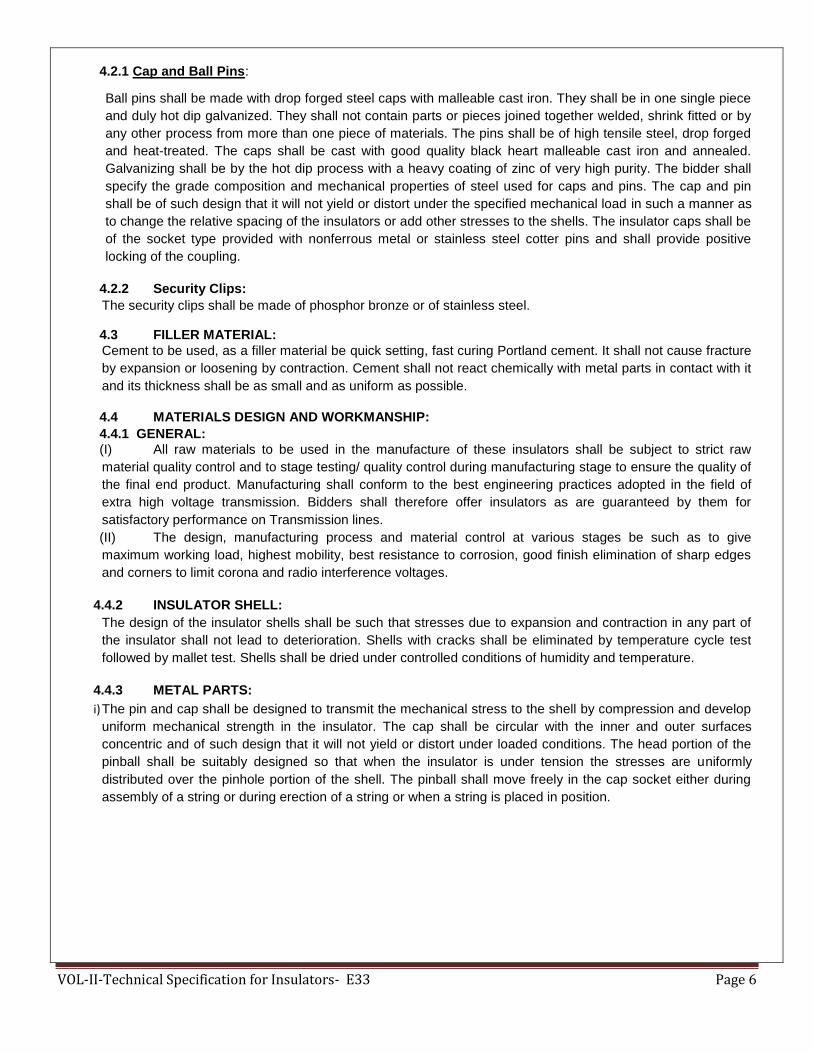
VOL-II-Technical Specification for Insulators- E33 Page 6
4.2.1 Cap and Ball Pins:
Ball pins shall be made with drop forged steel caps with malleable cast iron. They shall be in one single piece
and duly hot dip galvanized. They shall not contain parts or pieces joined together welded, shrink fitted or by
any other process from more than one piece of materials. The pins shall be of high tensile steel, drop forged
and heat-treated. The caps shall be cast with good quality black heart malleable cast iron and annealed.
Galvanizing shall be by the hot dip process with a heavy coating of zinc of very high purity. The bidder shall
specify the grade composition and mechanical properties of steel used for caps and pins. The cap and pin
shall be of such design that it will not yield or distort under the specified mechanical load in such a manner as
to change the relative spacing of the insulators or add other stresses to the shells. The insulator caps shall be
of the socket type provided with nonferrous metal or stainless steel cotter pins and shall provide positive
locking of the coupling.
4.2.2 Security Clips: The security clips shall be made of phosphor bronze or of stainless steel. 4.3 FILLER MATERIAL: Cement to be used, as a filler material be quick setting, fast curing Portland cement. It shall not cause fracture
by expansion or loosening by contraction. Cement shall not react chemically with metal parts in contact with it
and its thickness shall be as small and as uniform as possible.
4.4 MATERIALS DESIGN AND WORKMANSHIP: 4.4.1 GENERAL:
(I) All raw materials to be used in the manufacture of these insulators shall be subject to strict raw
material quality control and to stage testing/ quality control during manufacturing stage to ensure the quality of
the final end product. Manufacturing shall conform to the best engineering practices adopted in the field of
extra high voltage transmission. Bidders shall therefore offer insulators as are guaranteed by them for
satisfactory performance on Transmission lines.
(II) The design, manufacturing process and material control at various stages be such as to give
maximum working load, highest mobility, best resistance to corrosion, good finish elimination of sharp edges
and corners to limit corona and radio interference voltages.
4.4.2 INSULATOR SHELL: The design of the insulator shells shall be such that stresses due to expansion and contraction in any part of
the insulator shall not lead to deterioration. Shells with cracks shall be eliminated by temperature cycle test
followed by mallet test. Shells shall be dried under controlled conditions of humidity and temperature.
4.4.3 METAL PARTS:
i) The pin and cap shall be designed to transmit the mechanical stress to the shell by compression and develop
uniform mechanical strength in the insulator. The cap shall be circular with the inner and outer surfaces
concentric and of such design that it will not yield or distort under loaded conditions. The head portion of the
pinball shall be suitably designed so that when the insulator is under tension the stresses are uniformly
distributed over the pinhole portion of the shell. The pinball shall move freely in the cap socket either during
assembly of a string or during erection of a string or when a string is placed in position.

VOL-II-Technical Specification for Insulators- E33 Page 7
ii) Metal caps shall be free from cracks, seams, shrinks, air holes, blowholes and rough edges. All
metal surfaces shall be perfectly smooth with no projecting part or irregularities, which may cause corona. All
load bearing surfaces shall be smooth and uniform so as to distribute the loading stress uniformly. Pins shall
not show any microscopically visible cracks, inclusions and voids.
4.4.4 GALVANIZING:
All ferrous parts, shall be hot dip galvanized in accordance with IS: 2629. The zinc to be used for galvanizing
shall conform to grade Zn 99.95 as per IS: 209. The zinc coating shall be uniform, smoothly adherent,
reasonably light, continuous and free from impurities such as flux, ash, rust stains, bulky white deposits and
blisters. Before ball fittings are galvanized, all die flashing on the shank and on the bearing surface of the ball
shall be carefully removed without reducing the designed dimensional requirements.
4.4.5 CEMENTING:
The insulator design shall. Be such that the insulating medium shall not directly engaged with hard metal.
The surface of porcelain and coated with resilient paint to offset the effect of difference in thermal expansions
of these materials. High quality Portland cement shall be used for cementing the porcelain to the cap & pin.
4.4.6 SECURITY CLIPS (LOCKING DEVICES)
The security clips to be used as locking device for ball and socket coupling shall be „R‟ shaped hump type to
provide for positive locking of the coupling as per IS: 2486 (Part-IV). The legs of the security clips shall allow
for spreading after installation to prevent complete withdrawal from the socket. The locking device shall
resilient corrosion resistant and of sufficient mechanical strength. There shall be no possibility of the locking
device to be displaced or be capable of rotation, which placed in position, and under no circumstances shall it
allow separation of insulator units and fittings. „W‟ type security clips are also acceptable. The hole for the
security clip shall be counter sunk and the clip shall be of such design that the eye of the clip may be
engaged by a hot line clip puller to provide for disengagement under energized conditions. The force required
for pulling the clip into its unlocked positions shall not be less than 50 N (5 kg.) or more than 500 N (50 kgs.).
4.4.7 MARKING:
Each insulator shall have the rated combined mechanical and electrical strength marked clearly on the
porcelain surface. Each insulator shall also bear symbols identifying the manufacturer, month, and year of
manufacture. Marking on porcelain shall be printed, not impressed, and shall be applied before firing
4.5 BALL AND SOCKET DESIGNATION:
The dimensions of the ball and sockets for 70 and 90 KN insulator strings shall be of 16 mm and for 120 KN
and 160 KN insulator strings shall be of 20 mm designation in accordance with the standard dimensions stated
in IS: 2486 (Part-II).
4.6 DIMENSIONAL TOLERANCE OF INSULATOR DISCS: It shall be ensured that the dimensions of the disc insulators are within the limits specified below:
(a)
Sl. Diameter of Disc (mm) Standard in Maximum Minimum
No. Mm
1. 70 KN/90 KN & 120 KN 255/255 & 280 As per IS As per IS
2. 160 KN 305 As per IS As per IS

VOL-II-Technical Specification for Insulators- E33 Page 8
(b)
Sl. Ball to Ball spacing Standard in Maximum Minimum
No.
Between Discs (mm)
Mm
1. 70 KN/90 KN/120 KN 145 As per IS As per IS
2. 160 KN 170 As per IS As per IS
NOTE: Tolerance as per relevant IS (Latest edition).
(4.7) GUARANTEED TECHNICAL PARTICULARS
FOR ANTIFOG DISC INSULATORS
Sl. DESCRIPTION 70 KN 90 KN 120KN 160 KN
No.
1. Manufacture‟s name
&address 2 Type of Insulator Ball & Ball & Ball & Ball &
Socket socket socket socket
3 Size of ball & socket 16B 16B 20 20
4 Dimensions
(a) Disc diameter 255 255 280 305
(b) Unit spacing 145 145 145 170 (c) Creepage distance of the 430 430 430 475
single insulator-mm
5 Electro-mechanical strength of single insulator-kN 70 90 120 160
6 Materials of shell Porcelain Porcelain Porcelain Porcelain
7 Electrical value
7.1 Power frequency Withstand Voltage Disc (a) Dry-kV (rms) (b) Wet-kV (rms)
80 45
80 45
85 50
90 50
7.2 Power frequency Withstand Voltage Disc (a) Dry-kV (rms) (b) Wet-kV (rms)
85 50
85 50
90 55
95 55
7.3 Impulse Withstand Voltage Disc 1.2/50 micro second (a) Positive – kV(Peak) (b) Negative – kV(Peak)
125 125
125 125
130 130
135 135
7.4 Impulse Flashover Voltage Disc 1.2/50 micro second (a) Positive – kV(Peak) (b) Negative – kV(Peak)
135 130
135 130
140 135
145 140
4.8 INTERCHANGEABILITY:
The insulators inclusive of the ball and socket fittings shall be of standard design suitable for use with
hardware fittings of any make conforming to relevant Indian Standards.
4.9 CORONA AND RIV PERFORMANCE:
All surfaces shall be even, smooth, without cuts, abrasions or projections. No part shall be subject to
excessive localized pressure. The metal parts and porcelain shall not produce any noise-generating corona
under all operating conditions.

VOL-II-Technical Specification for Insulators- E33 Page 9
5.0 SUITABILITY FOR LIVE LINE MAINTENANCE:
The insulator shall be compatible for use with hot line or live line maintenance techniques so that usual hot
line operation can be carried out with easy speed and safety.
5.1 FREEDOM FROM DEFECTS:
Insulators shall have none of the following defects:
1) Ball pin shake.
2) Cementing defects near the pin like small blow holes, small hair cracks lumps etc.
3) Sand fall defects on the surface of the insulator.
5.2 INSULATOR STRINGS: 5.2.1 TYPE AND RATING:
The insulator strings shall be formed with standard discs described in this specification for use on 3 phases
132/22 KV 50 Hz effectively earthed systems in an atmosphere with pollution level as indicated in project
synopsis. Suspension insulator strings for use with suspension/tangent towers are to be fitted with discs
70/90 KN EMS rating while tension insulator strings for use with Anchor/ Tension towers are to be fitted
with discs of 120 KN / 160 KN EMS level rating.
5.2.2 STRING SIZE: The sizes of the disc insulator, the number to be used in different types of strings, their electro-mechanical
strength and minimum nominal creep age distance shall be as given in clause 3.12
5.3 STRING CHARACTERISTICS
5.3.1 The characteristics of the complete string shall be as follows:
Sl. Description. Suspension. Tension.
No.
132KV 220kV 132KV 220KV
I Switching surge withstand voltage (dry& wet)KV Peak - - - -
Ii Lighting impulse withstand voltage (dry) KV Peak. 650 1050 650 1050
Iii Power frequency without voltage (wet) KV r.m.s. 275 460 275 460
Iv. Corona extinction voltage level KV rms - 176 - 176
v. Max. RIV for comp. Etc. strong including corona rings at 156
KV (rms). … hours clamps etc. at 1.1. times maximum knee to ground voltage (micro volts).
- 500 - 500
vi. Mechanical failing load for each string (kgf) 6500 11500 11500 15500
Vii. No deformation load for each string (kgf) - 7705 - 10385
Viii. Max. voltage across any disc. 13% 13% 13% 13%
5.3.2 Insulator units after assembly shall be concentric and coaxial within limits as permitted by Indian Standards.
5.3.3 The strings design shall be such that when units are coupled together there shall be contact
between the shell of one unit and metal of the adjacent unit.
5.4 TECHNICAL DESCRIPTION OF PORCELAIN LONG ROD INSULATORS
5.4.1 Details of Long Rod Insulators

VOL-II-Technical Specification for Insulators- E33 Page 10
5.4.2 The insulator string shall consist of standard porcelain long rod insulators with normal sheds for a three phase, 50 Hz, effectively earthed 132/220/400 kV transmission system. Insulators shall be long rod type with Ball and socket connections.
5.4.3 Insulators shell has normal sheds/alternate sheds with good self-cleaning properties. Insulator shed profile, spacing projection etc. shall be strictly in accordance with the recommendation of IEC-60815.
5.4.4 The size of long rod insulator, minimum creepage distance, the number to be used in different type of strings, their electromechanical strength and mechanical strength of insulator string alongwith hardware fittings shall be as follows :
5.4.5 Description of long rod insulator string (equivalent to disc insulator string)
5.5 PRINCIPAL PARAMETERS OF THE PORCELAIN LONG ROD INSULATORS:-
Sl. No.
System Voltage (kV)
Type of String.
Length of Porcelain long rod
Insulator (mm)
Minimum
creepage
distance of Porcelain long rod Insulator(mm),
No. of Porcelain long rod Insulator units per string
Electro- mechanical strength of Porcelain long rod Insulator string fittings (KN)
1. 132 Single Suspension 1305 2628 1 X 1
1 X 70kN
2. 132 Double Suspension
1305 2628 2 X 1
2 X 70kN
3. 132 Single Tension 1450 2920 1 X 1 1 X 120kN
4. 132 Double Tension 1450 2920 2 X 1 2 X 120kN
5. 132 Single Suspension 1305 3625 1 X 1
1 X 70kN
6. 132 Double Suspension
1305 3625 2 X 1 2 X 70kN
7. 132 Single Tension 1450 3625 1 X 1 1 X 120kN
8. 132 Double Tension 1450 3625 2 X 1 2 X 120kN
9. 132 Single Tension 1700 3625 1 X 1 1 X 160kN
10. 132 Double Tension 1700 3625 2 X 1 2 X 160kN
11. 220 Single Suspension 2030 4088 1 X 2 1 X 90kN
12. 220 Double Suspension
2030 4088 2 X 2
2 X 90kN
13. 220 Single Tension 2175 4380 1 X 2 1 X 120kN
14. 220 Double Tension 2175 4380 2 X 2 2 X 120kN
15. 220 Single Suspension 2030 5180 1 X 2
1 X 90kN

VOL-II-Technical Specification for Insulators- E33 Page 11
(i) Bidders may quote for the relevant strings. (ii) Length of long rod insulator strings shall be matching with the corresponding disc insulator strings.
5.5.1 STANDARD TECHNICAL PARTICULARS FOR 132kV PORCELAIN LONG ROD INSULATOR STRING
Sl. Description Unit
Standard Technical Particular value
70 KN/ 90KN Insulator
120 KN Insulator
160 KN Insulator
1.0 General
a)
Size and Designation of ball & Socket assembly
mm 16 mm Alt-B as per IS 2486 / IEC: 60120
20 as per IS 2486/
IEC: 60120
20 as per IS 2486/
IEC: 60120
2.0 Dimensions
a) Core diameter mm 55 to 75 60 to 75 75 to 85
b) Tolerance on core diameter + mm (0.04d+1.5) (0.04d+1.5)
(0.04d+1.5)
c) Minimum nominal creepage distance 1. Normal 2. Anti Fog
mm 2628 2920 -----
3625 3625 3625
3.0 Colour of glaze of finished porcelain insulator Brown Brown Brown
4.0 Mechanical Strength of Long Rod kN 70 120 160
5.0 Minimum electrical values
a) Power frequency Withstand voltage
(DRY/WET)
kV rms 310/275 310/275 310/275
b) Power frequency Flashover voltage
(DRY/WET)
kV rms 325/295 325/295 325/295
c) Impulse Withstand test voltage 1.2 x 50 μs
(Dry) POSITIVE / NEGATIVE
kV(pea
k)
650/650 650/650 650/650
d) Impulse Flashover test voltage 1.2 x 50 μs
(Dry) POSITIVE / NEGATIVE
kV(pea
k)
670/670 670/670 670/670
16. 220 Double suspension
2030 5180 2 X 2 1 X 90kN
17. 220 Single Tension 2175 5550 1 X 2 1 X 120kN
18. 220 Double Tension 2175 5550 2 X 2 2 X 120kN
19. 220 Single Tension 2550 5550 1 X 2 1 X 160kN
20. 220 Double Tension 2550 5550 2 X 2 2 X 160kN
21. 400 Single Suspension 3335 9200 1 X 3
1 X 120kN
22. 400 Double suspension 3335 9200 2 X 3 2 X 120kN
23. 400 Single Tension 3910 9200 1 X 3 1 X 160kN
24. 400 Double Tension 3910 9200 2 X 3 2 X 160kN

VOL-II-Technical Specification for Insulators- E33 Page 12
5.5.2 STANDARD TECHNICAL PARTICULARS FOR 220kV PORCELAIN LONG ROD INSULATOR STRING
Sl. Description Unit
Standard Technical Particular value
70 KN Insulat
or
90 KN Insulator
120 KN Insulator
160 KN Insulator
1.0 General
a)
Size and Designation of ball & Socket assembly
mm ----- 16 mm Alt-B as per IS 2486/ IEC: 60120
20 as per IS 2486/ IEC: 60120
20 as per IS 2486/ IEC: 60120
2.0 Dimensions -----
a) Core diameter mm ----- 55 to 75 60 to 75 75 to 85
b) Tolerance on core diameter + mm ----- (0.04d+1.5) (0.04d+1.5) (0.04d+1.5)
c) Minimum nominal creepage distance 1. Normal 2. Anti Fog
mm ----- 4088 4380 -----
----- 5180 5550 5550
3.0 Colour of glaze of finished porcelain insulator
----- Brown Brown Brown
4.0 Mechanical Strength of Long Rod kN ----- 90 120 160
5.0 Minimum electrical values -----
a) Power frequency Withstand
voltage(DRY/WET)
kV
rms
----- 500/460 500/460 500/460
b) Power frequency Flashover
voltage(DRY/WET)
kV
rms
----- 520/480 520/480 520/480
c) Impulse Withstand test voltage 1.2 x 50
μs (Dry) POSITIVE / NEGATIVE
kV(pe
ak)
----- 1050/1050 1050/1050 1050/1050
d) Impulse Flashover test voltage 1.2 x 50
μs (Dry) POSITIVE / NEGATIVE
kV(pe
ak)
----- 1100/1100 1100/1100 1100/1100
e) Corona extinction voltage level
kV
rms
----- 156 156 156
f) Max. RIV for string including corona rings at 156kV rms
micro
volts
----- 500 500 500
6.0 Eccentricity of Long Rod
6.
0
Eccentricity of Long Rod
a) Max. axial/radial run out 1.2 % of insulator length
1.2 % of insulator length
1.2 % of insulator length
b) Max. angular displacement deg 15 15 15
7.
0
Galvanizing
a) Minimum mass of zinc coating Gm/
sq.m.
600 600 600
b) Minimum no. of one minute dips in the
standard preece test
Nos. 6 dips 6 dips 6 dips
c) Minimum purity of zinc used for
galvanizing
% 99.95 99.95 99.95

VOL-II-Technical Specification for Insulators- E33 Page 13
a) Max. axial/radial run out ----- 1.2 % of insulator length
1.2 % of insulator length
1.2 % of insulator length
b) Max. angular displacement deg ----- 15 15 15

VOL-II-Technical Specification for Insulators- E33 Page 14
7.0
Galvanizing
a) Minimum mass of zinc coating Gm/ sq.m.
----- 600 600 600
b) Minimum no. of one minute dips in the standard preece test
Nos. ----- 6 dips 6 dips 6 dips
c) Minimum purity of zinc used for galvanizing % ----- 99.95 99.95 99.95
5.5.3 STANDARD TECHNICAL PARTICULARS FOR 400kV PORCELAIN LONG ROD INSULATOR STRING
Sl. Description Unit
Standard Technical Particular value
70 KN Insulator
90 KN Insulator
120 KN Insulator
160 KN Insulator
1.0 General
a)
Size and Designation of ball & Socket assembly
mm ----- ----- 20 as per IS 2486/ IEC: 60120
20 as per IS 2486/ IEC: 60120
2.0 Dimensions ----- -----
a) Core diameter mm ----- ----- 60 to 75 75 to 85
b) Tolerance on core diameter + mm ----- ----- (0.04d+1.5) (0.04d+1.5)
c) Minimum nominal creepage distance 1. Normal 2. Anti Fog
mm ----- ----- ----- -----
----- ----- 9200 9200
3.0 Colour of glaze of finished porcelain insulator
----- ----- Brown Brown
4.0 Mechanical Strength of Long Rod kN ----- ----- 120 160
5.0 Minimum electrical values ----- -----
a) Power frequency Withstand voltage
(DRY/WET)
kV rms ----- ----- 720/680 720/680
b) Power frequency Flashover voltage
(DRY/WET)
kV rms ----- ----- 740/700 740/700
c) Impulse Withstand test voltage 1.2 x 50
μs (Dry) POSITIVE / NEGATIVE
kV(peak
)
----- ----- 1550/1550 1550/1550
d) Impulse Flashover test voltage 1.2 x 50
μs (Dry) POSITIVE / NEGATIVE
kV(peak
)
----- ----- 1600/1600 1600/1600
e) Wet Switching impulse withstand
voltage (POSITIVE / NEGATIVE)
kV(peak
)
----- ----- 1050/1050 1050/1050
f) Corona extinction voltage level kV rms ----- ----- 320 320
g) Max. RIV for string including corona rings at 320kV rms
micro
volts
----- ----- 1000 1000
6.0 Eccentricity of Long Rod
a) Max. axial/radial run out ----- ----- 1.2 % of insulator length
1.2 % of insulator length
b) Max. angular displacement deg ----- ----- 15 15
7.0 Galvanizing
a) Minimum mass of zinc coating Gm/
sq.m.
----- ----- 600 600
b) Minimum no. of one minute dips in
the standard preece test
Nos. ----- ----- 6 dips 6 dips
c) Minimum purity of zinc used for
galvanizing
% ----- ----- 99.95 99.95

VOL-II-Technical Specification for Insulators- E33 Page 15
6.0 SPECIFICATION DRAWINGS: The specification in respect of the long rod insulators indicated above is given at Annexure-II. This specification is for information and guidance of the bidder only. The drawings to be furnished by the supplier shall be as per his own design and manufacture and shall be in line with the specification.
7.0 GENERAL TECHNICAL REQUIREMENTS:
7.1 PORCELAIN: The porcelain used in the manufacture of the shell shall be nonporous of high dielectric, mechanical and thermal strength free from internal stress blisters and thermal strength from internal stresses blisters, laminations, voids, foreign matter. Imperfections or other defects, which might render it in any way unsuitable for insulator shells. Porcelain shall remain unaffected by climatic conditions, ozone, acid alkalis, and zinc of dust. The manufacturing shall be by the wet process and impervious character obtained by through vitrification.
7.2 PORCELAIN GLAZE: Surfaces to come in contact with cement shall be made rough by stand glazing. All other exposed surfaces shall be glazed with ceramic materials having the same temperature coefficient of expansion as that of the insulator shell. The thickness of the glaze shall be uniform throughout and the colour of the glaze shall be brown. The glaze shall have a visible luster and smooth on surface and be capable of satisfactory performance under extreme tropical climatic weather conditions and prevent ageing of the porcelain. The glaze shall remain under compression on the porcelain body throughout the working temperature range.
7.3 METAL PARTS: 7.3.1 Cap and Ball pins: Twin Ball pins shall be made with drop forged steel and caps with malleable cast iron. They shall be in one
single piece and duly hot dip g galvanized. They shall not contain parts or pieces joined together, welded, shrink
fitted or by any other process from more than one piece of material. The pins shall be of high tensile steel, drop
forged and heat malleable cast iron and annealed. Galvanizing shall be by the hot dip process with a heavy
coating of zinc of very high purity with minimum of 6 dips. The bidder shall specify the grade, composition and
mechanical properties of steel used for caps and pins.
7.3.2 SECURITY CLIPS: The security clips shall be made of phosphor bronze or of stainless steel.
7.4 FILLER MATERIAL: Cement to be used as a filler material shall be quick setting, for curing Portland cement. It shall not cause fracture by expansion or loosening by contraction. Cement shall not react chemically with metal parts in contract with it and its thickness shall be as small and as uniform as possible.
8.0 MATERIAL DESIGN AND WORKMANSHIP: 8.1 GENERAL: i) All raw materials to be used in the manufacture of these insulators shall be subject to strict raw materials
quality control and to stage testing quality control during manufacturing stage to ensure the quality of the final
end product. Manufacturing shall conform to the best engineering practices adopted in the field of extra high
voltage transmission. Bidders shall therefore offer insulators as are guaranteed by them for satisfactory
performance on Transmission lines. ii) The design, manufacturing process and material control at various stages be such as to give maximum
working load, highest mobility, best resistance to corrosion good finish, elimination of sharp edges and corners to limit corona and radio interference voltage
8.2 INSULATOR SHELL:
The design of the insulator shell shall be such that stresses due to expansion and contraction in any part of the insulator shall not lead to deterioration. Shells with cracks shall be eliminated by temperature cycle test followed by temperature cycle test followed by mallet test. Shells shall be dried under controlled conditions of humidity

VOL-II-Technical Specification for Insulators- E33 Page 16
and temperature.
8.3 METAL PARTS: i) The twin ball pin and cap shall be designed to transmit the mechanical stresses to the shell by compression
and develop uniform mechanical strength in the insulator. The cap shall be circular with the inner and outer surfaces concentric and of such design that it will not yield or distort under loaded conditions. The head portion of the insulator or is under tension the stresses are uniformly distributed over the pinhole portion of the shell. The pinball shall move freely in the cap socket either during assembly of a string or during erection of a string or when a string is placed in position.
ii) Metal caps shall be free from cracks, seams, shrinks, air holes, blowholes and rough edges. All metal
surfaces shall be perfectly smooth with no projecting parts or irregularities which may cause corona. All load bearing surfaces shall be smooth and uniform so as to distribute the loading stresses uniformly. Pins shall not show any macroscopically visible cracks, insulations and voids.
8.4 GALVANIZING:
All ferrous parts shall be hot dip galvanized six times in accordance with IS: 2629. The zinc to be used for galvanizing shall conform to grade Zn 99.5 as per IS: 209. The zinc coating shall be uniform, smoothly adherent, reasonably light, continuous and free from impurities such as flux ash, rust stains, bulky white deposits and blisters. Before ball fittings are galvanized, all die flashing on the shank and on the bearing surface of the ball shall be carefully removed without reducing the designed dimensional requirements.
8.4.1 CEMENTING:
The insulator design shall be such that the insulating medium shall not directly engage with hard metal. The surfaces of porcelain and coated with resilient paint to offset the effect of difference in thermal expansions of these materials.
8.5 SECURITY CLIPS (LOCKING DEVICES The security clips to be used as locking device for ball and socket coupling shall be „R‟ shaped hump type to provide for positive locking of the coupling as per IS: 2486 (Part-IV). The legs of the security clips shall allow for sore adding after installation to prevent complete withdrawal from the socket. The locking device shall be resilient corrosion resistant and of sufficient mechanical strength. There shall be no possibility of the locking device to be displaced or be capable of rotation when placed in position and under no circumstances shall it allow separation of insulator units and fitting „W‟ type security clips are also acceptable. The hole for the security clip shall be countersunk and the clip shall be of such design that the eye of the clip may be engaged by a hot line clip puller to provide for disengagement under energized conditions. The force required for pulling the clip into its unlocked position shall not be less than 50 N (5 Kgs.) or more than 500N (50 Kgs.)
8.6 BALL AND SOCKET DESIGNATION: The dimensions of the balls and sockets for 80 KN long rod insulators shall be of 16mm and for 120 KN shall be of 20mm designation in accordance with the standard dimensions stated in IS: 2486 (Part-III).
8.7 DIMENSIONAL TOLERANCE OF PORCELAIN LONG ROD INSULATORS It shall be ensured that the dimensions of the long rod insulators are within the limits as per relevant IEC/ ISS.
9.0 TESTS (FOR DISC/PORCELAIN LONG ROD INSULATORS) : 9,1 The following tests shall be carried out on the insulator string and disc insulators.
9.2 TYPE TEST:
This shall mean those tests, which are to be carried out to prove the design, process of manufacture and general conformity of the material and product with the intents of this specification. These tests shall be conducted on a representative number of samples prior to commencement of commercial production. The Bidder shall indicate his schedule for carrying out these tests.
9.3 ACCEPTANCE:
This shall mean these tests, which are to be carried out on samples taken from each lot offered for pre-despatch inspection for the purpose of acceptance of the lot.
9.4 ROUTINE TESTS:
This shall mean those tests, which are to be carried out on each insulator to check the requirements, which

VOL-II-Technical Specification for Insulators- E33 Page 17
are likely to vary during production.
9.5 TESTS DURING MANUFACTURE: Stage tests during manufacture shall mean those tests, which are to be carried out during the process of manufacture to ensure quality control such that the end product is of the designed quality conforming to the intent of this specification.
9.6 TEST VALUE: For all type and acceptance tests the acceptance values shall be the value guaranteed by the bidder in the guaranteed technical particulars of the acceptance value specified in this specification of the relevant standard whichever is more stringent for that particular test.
9.7 TEST PROCEDURE AND SAMPLING NORMS:
The norms and procedure of sampling for the above tests shall be as per the relevant Indian Standard or the Internationally accepted standards. This will be discussed and mutually agreed to between the supplier and purchaser before placement of order. The standards and normal according to which these tests are to be carried out are listed against each test. Where a particular test is a specific requirement of this specification, the norms land procedure for the same shall be as specified in Annexure-IV attached hereto as mutually agreed to between the supplier and the purchaser in the quality assurance programme.
9.8 TYPE TESTS:
The following type test shall be conducted on a suitable number of individual unit components, materials or complete strings.
9.8.1 On the complete insulator string with hardware fittings.
a) Power frequency voltage withstand test with : IEC: 60383
corona control rings and under wet condition.
b) Switching surge voltage withstand test under : IEC: 60383
wet condition (For 400kV and above only)
c) Impulse voltage withstand test under dry : IEC: 60383
condition.
d)
Impulse voltage flashover test under dry : IEC: 60383
condition.
e) Voltage distribution test. : Applicable only for Disc insulators only
f) Corona & RIV test under dry condition. : As per this specification
g) Mechanical strength test. : As per this specification
h) Vibration. : As per this specification
9.8.2 On Insulators:
a) Verification of dimensions. : IS: 731/ IEC: 60383
b) Thermal mechanical performance test: : IEC:60575
c) Power frequency voltage withstand and : IEC: 60383
flashover
(I) dry (ii) wet.
d) Impulse voltage withstand flashover test (dry) : IEC: 60383
e) Visible discharge test (dry) : IS:731
f) RIV test (dry) : IS:8263/ IEC: 60437

VOL-II-Technical Specification for Insulators- E33 Page 18
All the type tests given under clause No.9.8.1 above shall be conducted on single suspension and Double Tension insulator string alongwith hardware fittings.
9.9 ACCEPTANCE TESTS: 9.9.1 For insulator:
a) Visual examination : IS:731/IEC:60383
b) Verification of dimensions. : IS:731/IEC:60383
c) Temperature cycle test. : IS:731/IEC:60383
d) Galvanizing test. : IS:731/IEC:60383
e) Mechanical performance test. : IEC:60575
f) Test on locking device for ball and socket : IEC:60372
coupling.
g) Eccentricity test. : IEC: 60383
h) Electro-mechanical/Mechanical strength test. : IEC: 60383 (Disc/Long Rod)
i) Puncture test. : IS:731 (Applicable only for Discs)
j) Porosity test. : IS:731/IEC:60383
9.10 ROUTINE TESTS:
9.10.1 For insulators:
a) Visual inspection. : IS:731/IEC:60383
b) Mechanical routine test. : IS:731/IEC:60383
c) Electrical routine test. : IEC:60383 (Applicable only for Discs)
9.11 TEST DURING MANUFACTURE: On all components as applicable. a) Chemical analysis of zinc used for galvanizing. : As per the Specification
b) Chemical analysis, mechanical and
metallographic test and magnetic particle : As per the Specification
inspection for malleable castings.
c) Chemical analysis, hardness test and : As per the Specification
magnetic particle inspection for forgings.
d) Hydraulic Internal Pressure tests on shell. : Applicable only for Discs
e) Crack detection test for metal parts. : As per the Specification
9.12 ADDITIONAL TEST:
The purchaser reserves the right for carrying out any other tests of a reasonable nature at the works of the supplier/ laboratory or at any other recognized laboratory/ research institute in addition to the above mentioned type, acceptance and routine tests at the cost of the purchaser to satisfy that the material complies with the intent of this specification.
9.13 CO-ORDINATION FOR TESTING:
For insulator strings, the supplier shall arrange to conduct testing of their disc/Porcelain long rod insulators with the hardware fittings to be supplied to the purchaser by other suppliers. The supplier is also required to guarantee overall satisfactory performance of the disc/Porcelain long rod insulator with the hardware fittings.
NOTE:
In respect of electrical tests on a complete string consisting of insulators and hardware guarantee of values of responsibility of testing shall be with hardware manufacturer of RIV, corona and voltage distribution test (Applicable for Disc insulator strings only) and with insulator manufacturer for all other tests.

VOL-II-Technical Specification for Insulators- E33 Page 19
9.14 TEST CHARGES AND TEST SCHEDULE:
9.14.1 TYPE TEST: The insulator offered shall be fully type tested as per this specification. In case the equipment of the type and design offered, has already been type tested in an independent test laboratory. The bidder shall furnish four sets of type test reports alongwith the offer. These tests must not have been conducted earlier than five years. The purchaser reserves the right to demand repetition of some or all type tests in the presence of purchasers‟ carrying representative. For this purpose the bidder may quote unit rates for carrying out each type test. These prices shall be taken into consideration for bid evaluation. For any change in the design/type already type tested and the design/type offered against this specification, purchaser reserves the right to demand repetition of tests without any extra cost.
9.14.2 ACCEPTANCE AND ROUTINE TEST:
All acceptance and routine tests as stipulated herein shall be carried out by the supplier in the presence of purchaser‟s representative.
9.14.3 Immediately after finalisation of the programme of type/ acceptance/ routine testing, the supplier shall give sufficient advance intimation to the purchaser to enable him to depute his representative for witnessing the tests.
For type tests involving tests on a complete insulator string with hardware fittings, the purchaser will advice the supplier of the hardware fittings to provide the necessary fittings to the place of the test.
9.14.4 In case of failure of the complete string in any type tests, the supplier whose product has failed in the tests, shall get the tests repeated at his cost. In case of any dispute, assessment of the purchaser as to the items that has caused the failure in any of the type tests shall be final and binding.
10. INSPECTION:
10.1
i. Purchaser and its representative shall at all times be entitled to have access to the works and to all places of
manufacturer where insulators are manufactured and the supplier shall afford all facilities to them for
unrestricted inspection of the works, inspection of materials, inspection of manufacturing process of insulators
and for conducting necessary tests as specified herein.
ii. The supplier shall keep the purchaser informed in advance of the time of starting and of progress of
manufacture of insulators in its various stages so that arrangements could be made for inspection.
iii. No material shall be dispatched from its point of manufacture unless the materials has been
satisfactorily inspected and tested.
iv. The acceptance of any quantity of insulators shall in no way relieve the supplier of his responsibility
for meeting all the requirement of this specification and shall not prevent subsequent rejection, if such insulators
are later found to be defective.
10.2 IDENTIFICATION / MARKING:
10.2.1 Each unit of insulator shall be legibly and indelibly marked with the trade mark of the supplier, the year of
manufacture, the guaranteed combined mechanical and electrical strength in kilo-newtons abbreviated by „KN‟
to facilitate easy identification and proper use.
10.2.2 The marking shall be on porcelain for porcelain insulators. The marking shall be printed and not
impressed and the same shall be applied before firing.
11. QUALITY ASSURANCE PLAN:
11.1 The bidder hereunder shall invariably furnish following information alongwith his offer, failing which
the offer shall be liable for rejection.
i. Statement giving list of important raw materials, names of sub-suppliers for the raw materials, list of standards
according to which the raw material are tested, list of tests normally carried out on raw materials in presence of

VOL-II-Technical Specification for Insulators- E33 Page 20
bidder‟s representative, copies of test certificates.
ii. Informations and copies of test certificates as in (i) above in respect of bought out materials.
iii List of manufacturing facilities available.
iv Level of automation achieved and lists of area where manual processing exists.
v List of areas in manufacturing process, where stage inspections are normally carried out in quality control and
details of such tests and inspection.
vi Special features provided in the equipment to make it maintenance free.
vii. List of testing equipping available with the bidder for final testing of equipment specified and test plant
limitation, if any, vis-à-vis the type, special, acceptance and routine tests specified in the relevant standards.
These limitations shall be very clearly brought out in schedule of deviations from specified test requirements.
11.2 The supplier shall within 30 days of placement of order submit the following information to the owner.
i) List of raw material and the names of sub-suppliers selected from those furnished alongwith the offer.
Sl.No. Description EMS value No of Discs
Size of Disc (mm)
CD of Disc (mm)
No of PLRI
Size of PLRI (mm)
CD of PLRI (mm)
1 132kV Single Suspension string 70/90KN – Normal
1 X 9 255 x 145 320 1 X 1 1305 2628
2 132kV Double Suspension string 70/90KN – Normal
2 X 9 255 x 145 320 2 X 1 1305 2628
3 132kV Single Suspension string 70/90KN – Anti Fog
1 X 9 255 x 145 430 1 X 1 1305 3625
4 132kV Double Suspension string 70/90KN – Anti Fog
2 X 9 255 x 145 430 2 X 1 1305 3625
5 132kV Single Suspension string 120KN – Anti Fog
1 X 10 280 x 145 430 1 X 1 1450 3625
6 132kV Double Suspension string 120KN – Anti Fog
2 X10 280 x 145 430 2 X 1 1450 3625
7 132kV Single Tension string 160KN – Anti Fog
1 X 10 305 x 170 475 1 X 1 1700 3625
8 132kV Double Tension string 160KN – Anti Fog
2 X10 305 X 170 475 2 X 1 1700 3625
9 220kV Single Suspension string 90KN – Normal
1 X 14 255 x 145 320 1 X 2 2030 4088
10 220kV Double Suspension string 90KN – Normal
2 X 14 255 x 145 320 2 X 2 2030 4088
11 220kV Single Suspension string 90KN – Anti Fog
1 X 14 255 x 145 430 1 X 2 2030 4380
12 220kV Double Suspension string 90KN – Anti Fog
2 X 14 255 x 145 430 2 X 2 2030 4380
13 220kV Single Suspension string 120KN – Anti Fog
1 X 15 280 x 145 430 1 X 2 2175 5180
14 220kV Double Suspension string 120KN – Anti Fog
2 X15 280 x 145 430 2 X 2 2175 5180
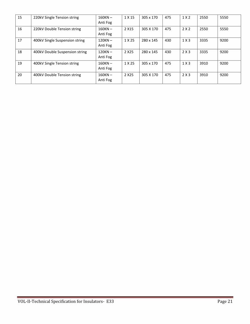
VOL-II-Technical Specification for Insulators- E33 Page 21
15 220kV Single Tension string 160KN – Anti Fog
1 X 15 305 x 170 475 1 X 2 2550 5550
16 220kV Double Tension string 160KN – Anti Fog
2 X15 305 X 170 475 2 X 2 2550 5550
17 400kV Single Suspension string 120KN – Anti Fog
1 X 25 280 x 145 430 1 X 3 3335 9200
18 400kV Double Suspension string 120KN – Anti Fog
2 X25 280 x 145 430 2 X 3 3335 9200
19 400kV Single Tension string 160KN – Anti Fog
1 X 25 305 x 170 475 1 X 3 3910 9200
20 400kV Double Tension string 160KN – Anti Fog
2 X25 305 X 170 475 2 X 3 3910 9200