common fittings for both piping and plumbing
TRANSCRIPT

Common fittings for both piping and plumbing
While there are hundreds of specialized fittings manufactured, some fittings are used widely in piping and plumbing systems.

Elbow
A pipe fitting installed between two lengths of pipe or tube allowing a change of direction, usually 90° or 45°. The ends may be machined for butt welding, threaded (usually female), or socketed, etc. When the two ends differ in size, it is called a reducing or reducer elbow.
Most elbows are available in short radius or long radius of types. The short radius elbows have a center to end distance equal to the NPS in inches, while the long radius is 1.5 times the NPS in inches. Short elbows are universally available; long elbows are readily available in Acrylonitrile butadiene styrene (ABS, plastic), PVC for DWV, sewage and central vacuums, and copper for 1950s to 1960s houses with copper drains.
Street elbow
A variant of the elbow, typically of male to female connections; see Street elbow.
Tee
A tee is used to either combine or split a fluid flow. Most common are tees with the same inlet and outlet sizes, but 'reducing' tees are available as well. Tee-fittings are also an integral part of the computer-enthusiast level watercooling solutions found in many modern enthusiast PCs. The fitting is one of the three main components of a T-Line, alongside an end-cap or fillport and a length of tubing. They are plumbed into the system, with the perpendicular barb (and its attached stretch of tubing leading to a fillport or a cap).
Cross
A cross has one inlet and three outlets, or vice versa. Crosses are common in fire sprinkler systems, but not in plumbing due to their extra cost as compared to using two tees.
The three outlets should be named in order. middle , right. For example 15-22-15
Coupling
A coupling connects two pipes to each other. If the material and size of the pipe are not the same, may be called a 'reducing coupling' or reducer, or an adapter. The term 'expander' is not used for a coupler that increases pipe size; instead 'reducer' is used. There are also fittings with stop and with out but according to this site there is no information about this.
Cap
A type of pipe fitting, often liquid or gas tight, which covers the end of a pipe.
Union

A union is similar to a coupling, except it is designed to allow quick and convenient disconnection of pipes for maintenance or fixture replacement. While a coupling would require either solvent welding or being able to rotate all the pipes adjacent as with a threaded coupling, a union provides a simple nut transition, allowing easy release at any time.
In addition to a standard union, there exist Dielectric Unions which are used to separate dissimilar metals (such as copper and galvanized steel) to avoid the damaging effects of electrolysis. When two dissimilar metals are placed in an acidic solution (most tap water is mildly acidic), they will form a battery and generate a voltage. If the two metals touch and conduct, the flow of current from one metal to the other will cause a movement of ions from one to the other, dissolving one metal and depositing on the other. A dielectric union breaks the electrical current with a plastic liner between two halves of the union.
Nipple
Short stub of pipe, usually threaded iron, brass or copper; occasionally just bare copper. A nipple is defined as being a short stub of pipe which has two male ends.
Additional common fittings for plumbing systems
Closet flange
The closet flange is the drain pipe flange to which a 'water closet' (toilet) is attached.
Clean-outs
Clean-outs are fittings that allow access to drains without removing plumbing fixtures. They are used for allowing an 'auger' or 'plumber's snake' to 'clean out' a plugged drain. Clean-outs should be placed in accessible locations through out a drainage system, and outside the building as these augers have limited length. The minimum is typically at the end of each branch, just ahead of each water closet, at the base of each stack, and both inside and outside the building in the building drain/sewer. Clean-outs normally have screwed-on caps.
Trap primers
Trap primers regularly inject water into traps so that water seals are maintained. This seal is necessary to keep sewer gases out of buildings.
Hydraulic fittings
Hydraulics use extremely high fluid pressures to create useful work, such as in the actuators for machinery such as backhoes. As such the hydraulic fittings are designed and rated for much greater pressures than those experienced in general piping systems and they are generally not compatible for use in general plumbing. More information on hydraulics and their fittings can be found in the hydraulic machinery article.

See also
Plumber Plumbing Water supply systems Traps, Drains, and Vents Rainwater, surface, and subsurface water drainage Septic systems Fuel gas, steam, and other piping Watercooling T-Line
INSTALLING WATER CLOSETS
The majority of water closets are installed using a closet flange, a bowl, and a flush tank or a flushometer valve. The flange is connected to the rough-in plumbing and secured to the floor, the bowl is attached to the flange, and the flush tank or flushometer is connected to the bowl. Finally, water service is connected to the tank.
Installing a closet flange. Use the following steps to install a closet flange (see Figure 20):
FIGURE 20. INSTALLING A CLOSET FLANGE
1. Slip the closet flange onto the closet bend, and make the joint connection for the type of piping used.

2. Secure the flange to the floor with fasteners.3. Slip bowl hold-down bolts into the bowl slots of the flange.
The flange is now ready for the bowl.
NOTE:
Flange joint connection to closet bend can be for cast-iron, plastic, and copper piping.
Flange can be secured to wooden, concrete, and tile floors, using the proper type fasteners.
Preparing a water closet bowl for installation. Use the following steps to prepare the bowl for installation (see Figure 21):
FIGURE 21. PREPARING CLOSET BOWL FOR INSTALLATION
1. Set the bowl upside down on paper to keep from scratching it.2. Place the wax gasket evenly over the horn, with the tapered side against the bottom of
the bowl.

3. Run a thick layer of putty around the base of the bowl.
The bowl is now ready to install.
Installing a water closet bowl to the floor. Use the following steps to install the bowl (see Figure 22):
FIGURE 22. INSTALLING WATER CLOSET BOWL TO FLOOR
1. Turn the bowl right side up, and place it so that the hold-down bolts pass through the bowl's bolt holes.
2. Slightly twist the bowl to smooth out the putty.3. Firmly press down on the bowl to seat the wax gasket.4. Place a washer over each bolt, and then fasten nuts on hand-tight.5. Check to see if bowl is level. If it is, tighten nuts. If not, use thin metal shims until it is
level, and then tighten nuts.6. Snap bolt cap on.
NOTE: Do not overtighten the nuts, as this will cause the bowl to crack.
Installing a water closet bowl to the wall. Use the following steps to install a wall-hung closet bowl (see Figure 23):

FIGURE 23. INSTALLING WATER CLOSET BOWL TO WALL
1. Following manufacturer's instructions, install a carrier body and connect it to the rough-in plumbing.
2. Install sealing gasket into opening at rear of closet bowl.3. Carefully pick up bowl, and set it against the wall so that the carrier's bolts pass through
the bowl's holes on both sides.4. Slide washer over each of the four bolts, and fasten nuts hand-tight to bolt.5. Use a carpenter’s level to make sure bowl is level.6. Tighten all nuts with a wrench and snap over nuts.
Primary Content Provider: U.S. ArmyPublisher: SweetHaven Publishing Services

LISTING WATER AND WASTE LINE FITTINGS
5. Fitting sizes are determined by the sizes of the pipe going to and from the fitting. This holds true for all water and waste line fittings.
a. Water line elbows are listed with the largest opening first. See figure 2-15
FIGURE 2-15. METHODS OF LISTING ELBOWS
b. Water line tees are listed with the run first, starting with the largest opening, and then the outlet. See figure 2-16.
FIGURE 2-16. METHODS OF LISTING TEES
c. For waste fittings, list bend sizes with the largest opening first. See figure 2-17. List Y branches with the run first, starting with the largest opening, and then the outlet,

FIGURE 2-17. METHODS OF LISTING WASTE FITTINGS
6. Obtain a list of water line fittings from the construction drawing diagram, rough-in information for each fixture and any other information indicated on the drawing.
a. The type and size of some fittings can be taken directly from the drawing. Fitting sizes are shown by the sizes of pipe going to and from a fitting. See examples in figure 2-18.

FIGURE 2-18. FITTING SIZES FOUND IN DIAGRAM
b. List the number of fittings by type and size.

TEES
one 2 x 3/4 x 3/4 inchone 2 x 3/4 inchthree 2 inch
ELBOWS
two 2 inchesone 3/4 inch
c. Find some fitting sizes from the rough-in information for a fixture. See figure 2-19. Note: The water closet rough-in diagram is furnished by the manufacturer.

FIGURE 2-19. FITTING SIZES FOUND IN ROUGH-IN INFORMATION
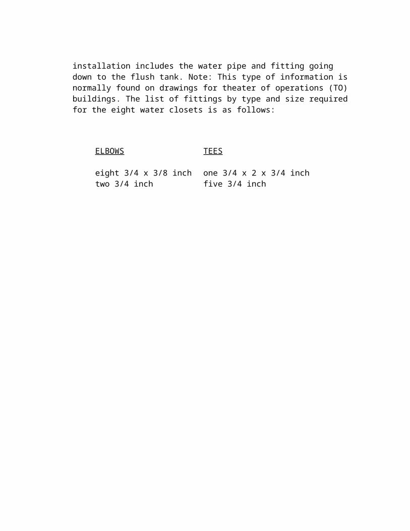
d. Find some fitting sizes from other information indicated on the drawing. In figure 2-20, the breakout in 11-C shows the method of installing one water closet. This installation includes the water pipe and fitting going down to the flush tank. Note: This type of information is normally found on drawings for theater of operations (TO)

buildings. The list of fittings by type and size required for the eight water closets is as follows:
ELBOWS
eight 3/4 x 3/8 inchtwo 3/4 inch
TEES
one 3/4 x 2 x 3/4 inchfive 3/4 inch

FIGURE 2-20. FITTINGS SIZES FOUND ADDED TO DIAGRAM
7. Obtain a list of water line valves by type and size from the construction drawing diagram and any other information indicated on the drawing. Valves are used in water lanes to start, control, and stop the flow of water. The water line going to and from the valve determines the size of the valve. A detailed breakout will show what is needed for installation. See detail 1 in figure 2-21. List valves and other fittings by type and size.
VALVES
three 2-inch gate valvesone 2-inch thermostatic mixing valve
OTHER FITTINGS
two 2- inch gate valvesone 2 1/2 x 2-inch bushing

FIGURE 2-21. VALVE SIZES FOUND IN DIAGRAM
8. Obtain a list of waste system fittings by size from the construction drawing and any other information indicated on the drawing.
a. Some waste system fitting sizes by type can be taken directly from the drawing. See figure 2-22.
b. List the number of fittings by type and size.

LATERAL Y
one 4-inch 45 degree regulartwo 4 x 2-inch 45 degree reducing
BENDS
one 4-inch 1/8 regularone 2-inch 1/8 regular
P-TRAPS
three 2-inch P-trapsone 4-inch P-trap
DRAIN
one 4-inch SD

FIGURE 2-22. WASTE SYSTEM FITTING SIZES FOUND IN DIAGRAM
9. Prepare a plumbing takeoff list for all the materials needed by type, size, and length for water supply service from point Z to all water closet tanks. Use the graphic scale (fig 2-23), construction drawing (fig 2-24), and the water closet breakout 11-G in figure 2-24. Make all measurements using the straightedge on a piece of paper. When you have completed your

takeoff list, check it with the information below.
FIGURE 2-23. GRAPHIC SCALE
10. The takeoff list from point Z to the water closet tanks is as follows:
STEEL PIPE
47 1/2 feet (approximately)
TEES
one 2 x 1 1/2 x 3/4 inchone 3/4 x 1 1/2 x 3/4 inchfive 3/4 inch
ELBOWS
two 3/4 incheight 3/4 x 3/8 inch

FIGURE 2-24. TAKEOFF LIST FOUND IN DIAGRAM
Primary Content Provider: U.S. ArmyPublisher: SweetHaven Publishing Services
MEASURING PIPE RUN LENGTHS

1. A plumber is often required to make a list of plumbing materials from a construction drawing or a set of construction drawings. The list must contain all the materials by type, size, and length to install a part of or the complete plumbing system.
2. Horizontal pipe run lengths are measured using either graphic or ratio construction scales.
a. To make graphic scale measurements with a divider, first spread the divider from the center of one fitting to the center of the next fitting to get the length of the pipe run (fig 2-1). Then place one end of the divider on 0 (fig 2-2). Where the other end falls on the scale is the pipe run length.
FIGURE 2-1. DIVIDER ON DIAGRAM
FIGURE 2-2. DIVIDER ON SCALE

b. To make graphic scale measurements with the straightedge of a piece of paper, place the straightedge along the pipe run and mark the center of each fitting (fig 2-3) on the paper. Then place one mark on 0 (fig 2-4). Where the other mark falls on the scale is the pipe run length.
FIGURE 2-3. STRAIGHTEDGE ON DIAGRAM
FIGURE 2-4. STRAIGHTEDGE ON SCALE
c. To make ratio scale measurements with a ruler, place the zero of the ruler at the center of one fitting and the measuring edge along the pipe run. Read the ruler mark at the center of the other fitting. See figure 2-5. If the ratio scale is 1/4 inch = 1 foot, the reading of 1 5/8 inches on the diagram means 6 feet 6 inches of pipe.

FIGURE 2-5. USE OF RULER WITH RATIO SCALE
3. Vertical water-pipe lengths are computed using simple math. The pipe run can come down from the ceiling level or up from below the floor level.
a. To determine a pipe run length from the ceiling level, use the floor-to-ceiling measurement, the distance the pipe hangs from the ceiling, and the fixture's rough-in measurements. To find the length of pipe X in figure 2-6, make the following computation:
Floor to ceilings -- 7 feet 11 inches.Pipe hangs from ceiling -- 0 feet 2 inches.Fixture rough-in measurement -- 4 feet 6 inches.7 feet 11 inches minus 0 feet 2 inches = 7 feet 9 inches.7 feet 9 inches minus 4 feet 6 inches = 3 feet3 inches.
The length of pipe X is 3 feet 3 inches

FIGURE 2-6. PIPE RUN FROM CEILING
b. To find a pipe run length from below floor level to ceiling, use the floor-to-ceiling measurement, the distance the pipe hangs from the ceiling, and the distance the pipe is below the floor. To find the length of pipe Z in figure 2-7, make the following computation:
Floor to ceiling -- 7 feet 11 inches.Pipe hang from ceiling -- 0 feet 2 inches.Pipe below floor -- 0 feet 4 inches.7 feet 11 inches minus 0 feet 2 inches -- 7 feet 9 inches.7 feet 9 inches plus 0 feet 4 inches -- 7 feet 13 inches or 8 feet 1 inch.
The length of pipe Z is 8 feet 1 inch:

FIGURE 2-7. PIPE RUN FROM BELOW FLOOR TO CEILING
c. To find a pipe run length from below floor level to a fixture, use the distance the pipe hangs below the floor and the fixture's rough-in measurements. To find the length of pipe Y in figure 2-8, make the following computation:
Pipe hangs from floor -- 3 inches.Fixture rough-in measurement -- 11 inches.11 inches plus 3 inches = 14 inches.
The length of pipe Y is 14 inches.

FIGURE 2-8. PIPE RUN FROM BELOW FLOOR TO FIXTURE
1. Use the graphic scale given in figure 2-9. What is the length, in feet, of line X?
FIGURE 2-9. USE OF GRAPHIC SCALE

Did you get 7 1/2 feet? If not, read Lesson 1, paragraph lb, again. If you did get 7 1/2 feet, good work. Continue with the lesson.
2. Use the ratio scale in figure 2-10. What is the length, in feet, of line Z?
FIGURE 2-10. USE OF GRAPHIC SCALE
Did you get 8 feet? If you did, good work. Continue with the lesson. If not, read Lesson 1, paragraph lb, again until you understand ratio scales.
3. Refer to figure 2-11. Compute the length of pipe Z.
FIGURE 2-11. MEASUREMENT OF PIPE

How did you do? Did you get 3 feet 8 inches for the length of pipe Z? Let's see how we got this answer.
Floor to ceiling -- 8 feet 0 inches.Pipe hangs from ceiling -- 4 inches.Fixture rough-in measurement -- 4 feet 0 inches.8 feet 0 inches minus 4 inches = 7 feet 8 inches.7 feet 8 inches minus 4 feet 0 inches = 3 feet 8 inches.
Therefore, the length of pipe Z is 3 feet 8 inches. If you have any problems with this computation, study the example closely. Get your squad leader or platoon sergeant to assist you if you need additional help. Then continue with the lesson.
4. Vertical waste-system-pipe lengths are computed in the same way as vertical water pipe.
a. To find a waste-pipe-run length from below the floor level to a fixture, use the distance from the center of the bend to the floor and the fixture's rough-in measurements. To find the length of pipe needed in figure 2-12, make the following computation:
Bend to floor -- 6 inches.Rough-in measurement -- 17 inches.6 inches plus 17 inches = 23 inches.
The length of pipe required is 23 inches.

FIGURE 2-12. VERTICAL WASTEPIPE
b. To find a waste-pipe length from below the floor up through the roof, use the total of all measurements from the bend below the floor to-VTR. To find the length of pipe needed in figure 2-13, make the following computation:
Bend to floorFloor to ceilingCeiling to roofRoof to top of VTRTotal
8 inches7 feet 11 inches2 feet 2 inches1 foot 0 inches10 feet 21 inches
The length of waste pipe required is 10 feet 21 inches or 11 feet 9 inches.

FIGURE 2-13. VERTICAL WASTE PIPE TO VTR
Refer to figure 2-14. Compute the length of the vent through the roof (VTR) shown.

FIGURE 2-14. VTR MEASUREMENT
Did you get 12 feet 1 inch? Let's see how we arrived at that answer.
If you had any problems with this exercise, look at the drawing again until you understand. Continue with the lesson.