comms expt4
DESCRIPTION
commsTRANSCRIPT
DE LA SALLE UNIVERSITY-DASMARIÑAS
College of Engineering, Architecture and Technology
ECET412L- PRINCIPLE OF COMMUNICATIONS LABORATORY
Expt. No. 4
Double Sideband AM with Full Carrier (DSBFC)
Submitted By:
Maria Rosalina C. Reyes
ECE41
August 19, 2014
Engr. Conrado D. Monzon
Instructor
OBJECTIVES
1. To investigate the dynamic characteristics of Double Sideband Full Carrier AM
signals.
2. To observe the behaviour of DSBFC AM signals with different modulating
signals.
3. To calculate the depth of modulation in AM using different methods.
4. To investigate the effects of overmodulation in AM signals.
5. To investigate the spectral characteristic of DSBFC.
THEORY/DISCUSSION
Double sideband (DSB) is one of the easiest modulation techniques to
understand, so it is a good starting point for the study of modulation. A type of DSB,
called binary phase-shift keying, is used for digital telemetry. Amplitude modulation
(AM) is similar to DSB but has the advantage of permitting a simpler demodulator, the
envelope detector. AM is used for broadcast radio, aviation radio, citizens’ band (CB)
radio, and short-wave broadcasting.
In radio communications, a sideband is a band of frequencies higher than or
lower than the carrier frequency, containing power as a result of the modulation
process. The sidebands consist of all the Fourier components of the modulated signal
except the carrier. All forms of modulation produce sidebands.
Amplitude modulation of a carrier wave normally results in two mirror-image
sidebands. The signal components above the carrier frequency constitute the upper
sideband (USB), and those below the carrier frequency constitute the lower sideband
(LSB). In conventional AM transmission, the carrier and both sidebands are present,
sometimes called double sideband amplitude modulation (DSB-AM).
In communication systems information is transmitted from one place to another
using electrical signals. Usually the information bearing signals are not suitable for
transmission due to its propagation qualities . Also, since these signals generally exist in
the same frequency range it is necessary to transmit them using different frequency
allocations to avoid interference. One of the methods used to solve these problems is
linear modulation, which is merely the frequency translation of the spectrum of the
information signal to a usually much higher frequency. The translated spectrum can be
modified before transmission in different forms resulting in different linear modulation
schemes. Specifically, there are four linear modulation methods: double-sideband
(DSB) (also known as double-sideband with suppressed carrier DSB-SC), amplitude
modulation (AM) or DSB-LC (large carrier), single-sideband (SSB) and vestigial-
sideband (VSB). This experiment examines the characteristics of the DSB modulation.
DATA AND RESULTS
SINUSOIDAL WAVE
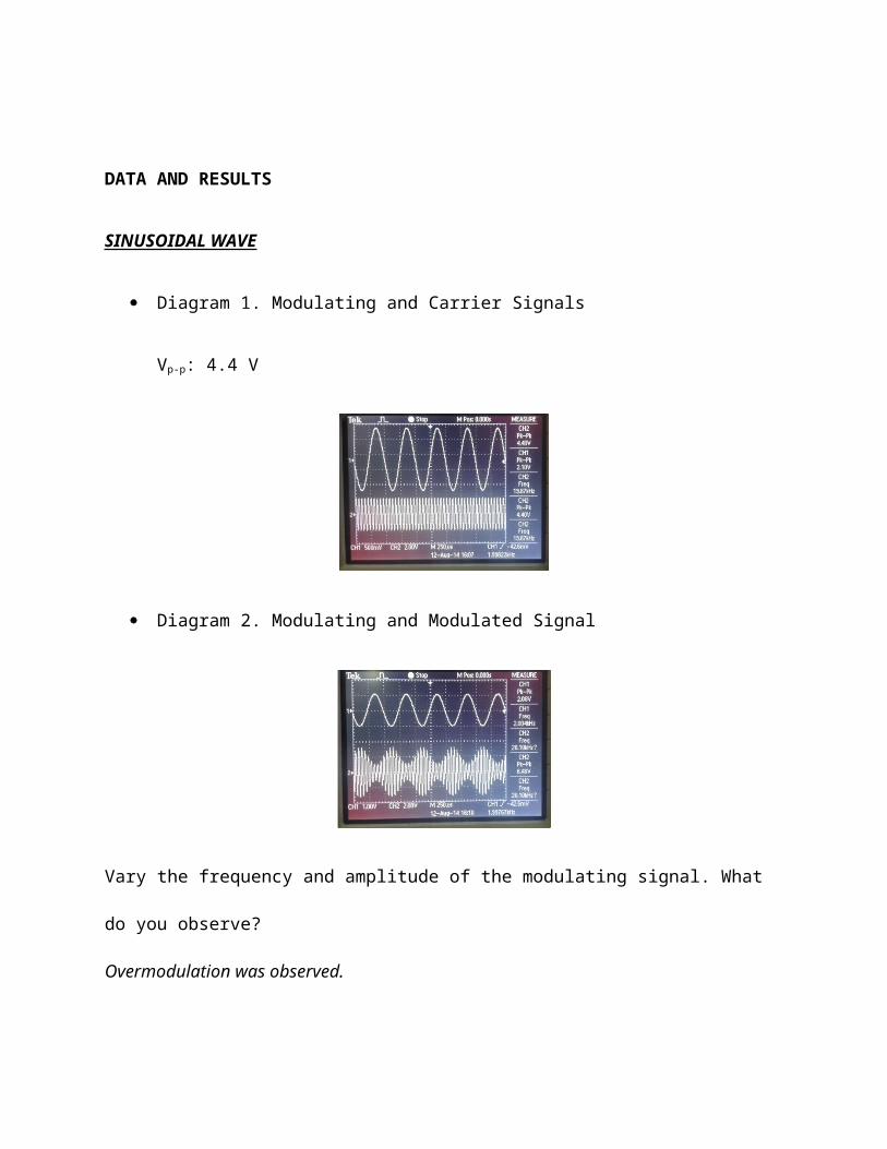
Diagram 1. Modulating and Carrier Signals
Vp-p: 4.4 V
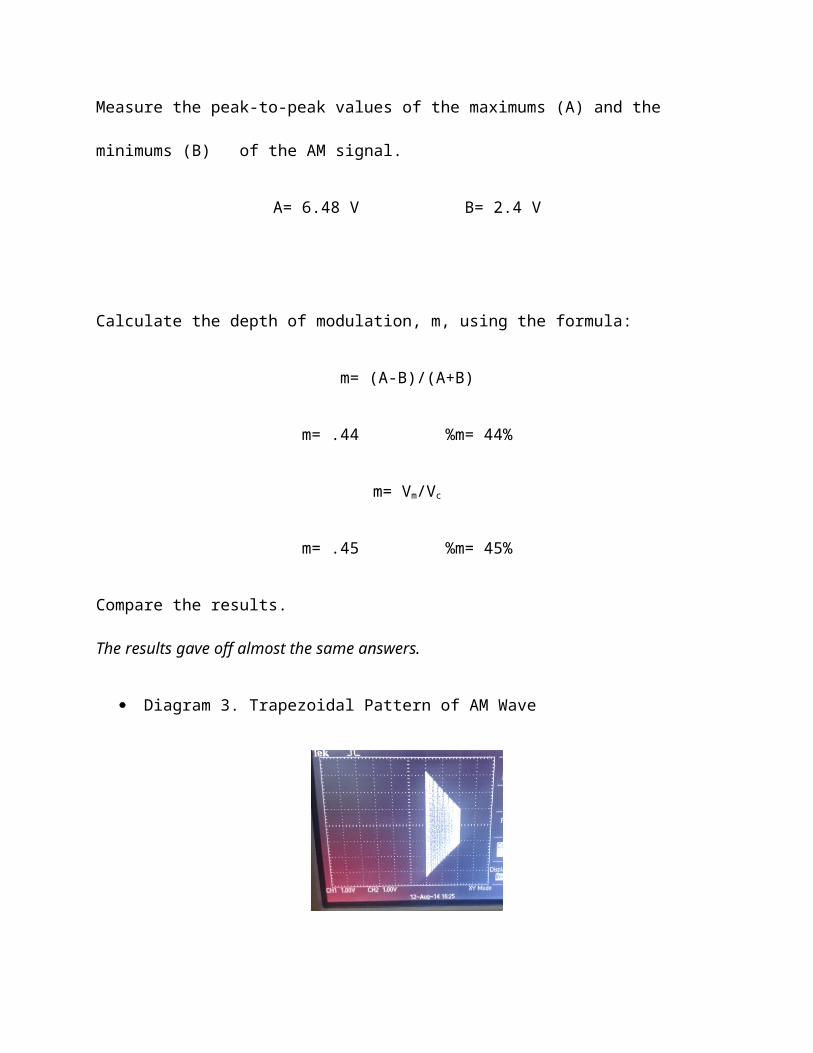
Diagram 2. Modulating and Modulated Signal
Vary the frequency and amplitude of the modulating signal. What do you observe?
Overmodulation was observed.
Measure the peak-to-peak values of the maximums (A) and the minimums (B) of the
AM signal.
A= 6.48 V B= 2.4 V
Calculate the depth of modulation, m, using the formula:
m= (A-B)/(A+B)
m= .44 %m= 44%
m= Vm/Vc
m= .45 %m= 45%
Compare the results.
The results gave off almost the same answers.
Diagram 3. Trapezoidal Pattern of AM Wave
Measure the longer vertical side of the trapezoid.
A= 6.5 V
Measure the shorter vertical side of the trapezoid.
B= 2.4 V
Calculate the depth of modulation, m, using the formula above as above with the
measurements obtained in the trapezoidal pattern.
m= .46 %m= 46%
What do you observe?
Based from the results obtained. The values of m, from the previous results is almost
the same with the trapezoidal pattern result.
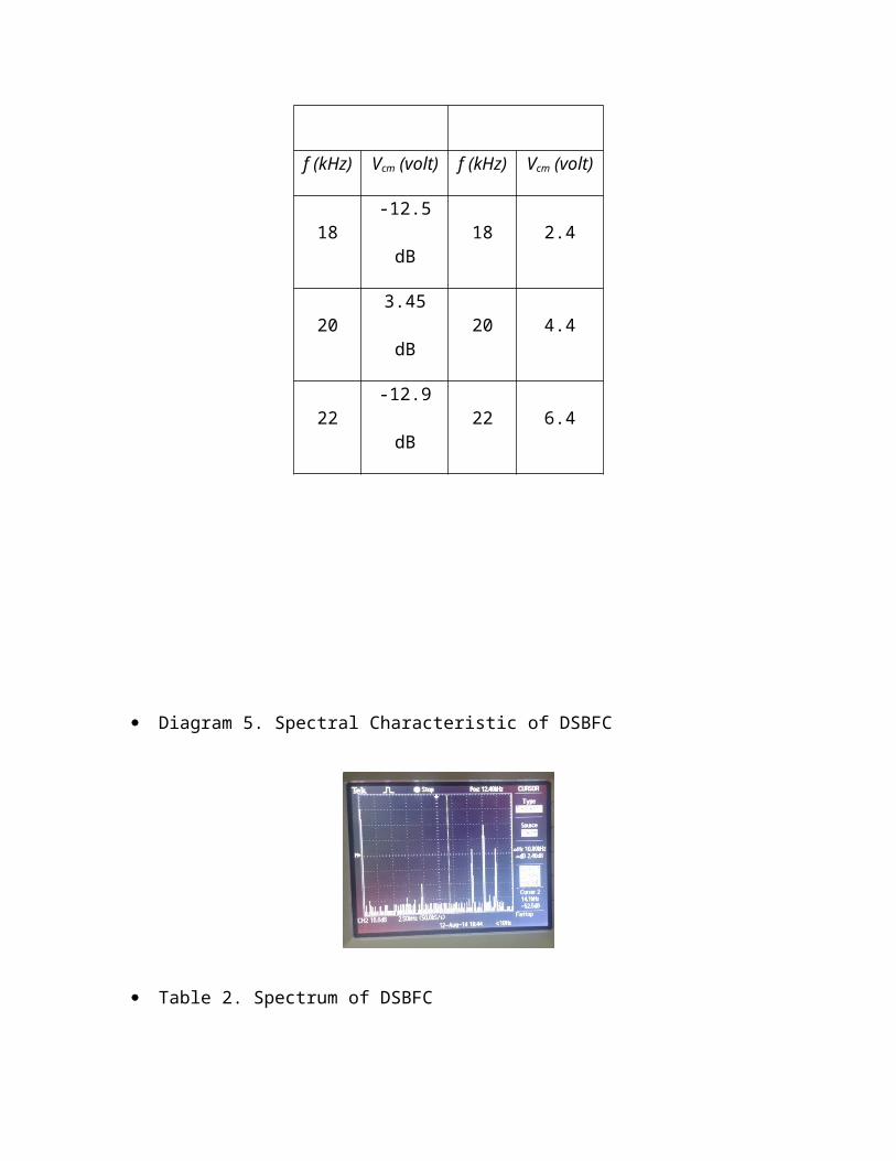
Diagram 4. Dynamic Characteristic of Overmodulated AM
Table 1. Spectrum of DSBFC
MEASURED THEORY
f
(kHz)Vcm (volt)
f
(kHz)Vcm (volt)
18 -12.5 dB 18 2.4
20 3.45 dB 20 4.4
22 -12.9 dB 22 6.4
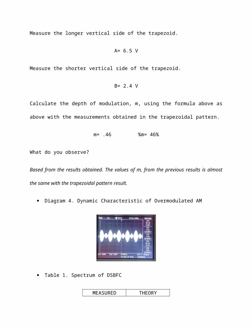
Diagram 5. Spectral Characteristic of DSBFC
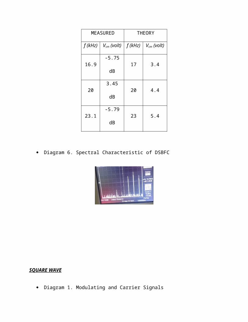
Table 2. Spectrum of DSBFC
MEASURED THEORY
f
(kHz)Vcm (volt)
f
(kHz)Vcm (volt)
16.9 -5.75 dB 17 3.4
20 3.45 dB 20 4.4
23.1 -5.79 dB 23 5.4
Diagram 6. Spectral Characteristic of DSBFC
SQUARE WAVE
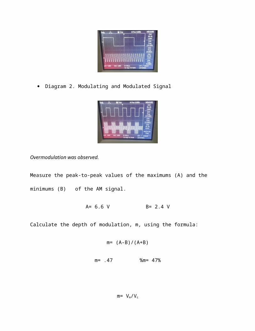
Diagram 1. Modulating and Carrier Signals
Diagram 2. Modulating and Modulated Signal
Overmodulation was observed.
Measure the peak-to-peak values of the maximums (A) and the minimums (B) of the
AM signal.
A= 6.6 V B= 2.4 V
Calculate the depth of modulation, m, using the formula:
m= (A-B)/(A+B)
m= .47 %m= 47%
m= Vm/Vc
m= .45 %m= 45%
Compare the results.
Both of them yield the same result.
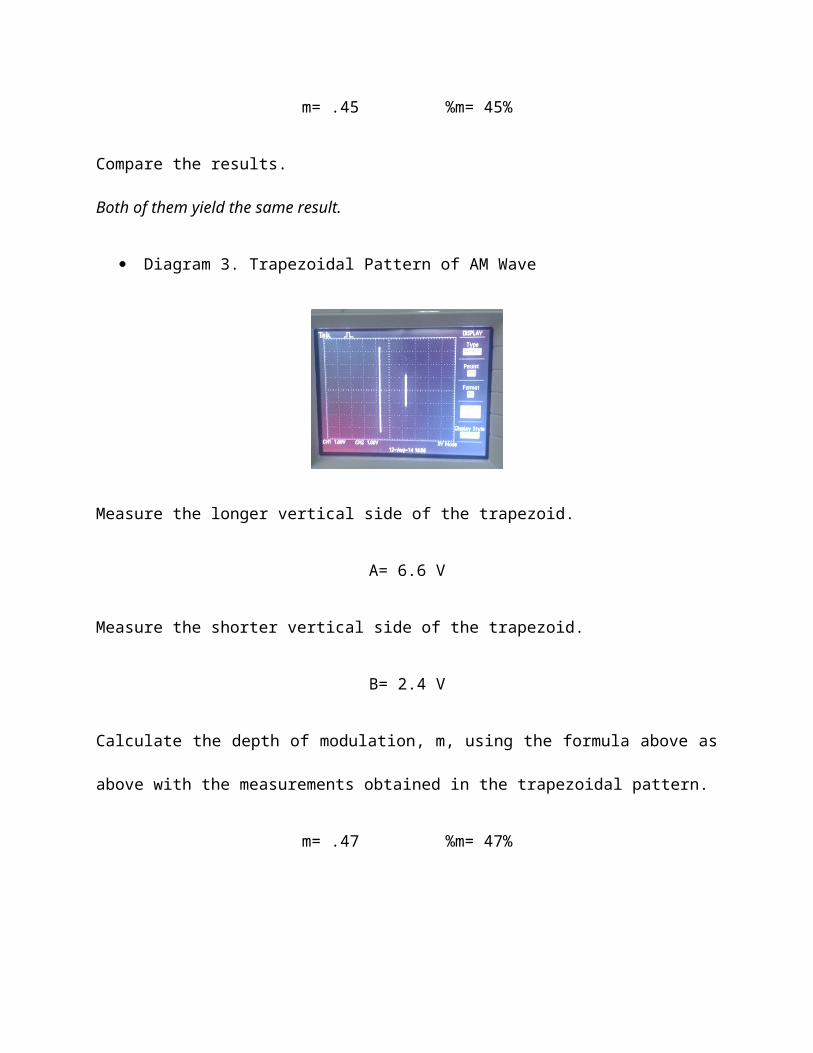
Diagram 3. Trapezoidal Pattern of AM Wave
Measure the longer vertical side of the trapezoid.
A= 6.6 V
Measure the shorter vertical side of the trapezoid.
B= 2.4 V
Calculate the depth of modulation, m, using the formula above as above with the
measurements obtained in the trapezoidal pattern.
m= .47 %m= 47%
What do you observe?
The trapezoidal pattern of the AM wave is the same with the previous results of m.
Diagram 4. Dynamic Characteristic of Overmodulated AM
OBSERVATION/CONCLUSION
Based form the experiment conducted, the Double Sideband Full Carrier is one
type of amplitude modulation. The carrier is then enveloped by the modulating signal
where it is being transmitted with a variation in its amplitude. This is one characteristic
of an AM signal. In a DSFBFC signal, the modulating signal, the upper sideband and
the lower sideband does not intersect each other. One characteristic an AM signal that
is also being exhibited by a DSBFC signal is the depth modulation. Depth modulation
can be calculated in many ways. First, by getting its peak-to-peak values of the
minimums and maximums of the signal and by simply getting the ratio of its sum and
difference a value of m can be obtained. Second, by getting the Vm and Vc of the signal
and dividing them. Lastly, the trapezoidal pattern method by determining the shorter and
longer side vertical side of the trapezoid, m can be determined. Any of these three
methods will yield to the same result. Overmodulated AM gives of more than 100%
modulation of the carrier, wherein the modulating signal creates smaller enveloped
signals. This is commonly a fault in transmission. It is referred to as “off the scale”
signal. The spectral characteristic of the AM signal gives the view wherein the signal is
plotted in frequency vs. time. The DSBFC spectral characteristics shows three
frequencies. The frequency itself, the modulating frequency and the carrier frequency.
Based on observation, these three were seen. The amplitude of the frequency is longer
and the amplitude of the fm and fc were the same, showing the sidebands.
REFERENCES
http://nptel.ac.in/courses/IIT-MADRAS/Principles_Of_Communication/pdf/Lecture19-
20_AM_DSB-SC.pdf
http://electronics.stackexchange.com/questions/107128/what-is-overmodulation
http://en.wikipedia.org/wiki/Amplitude_modulation
http://en.wikipedia.org/wiki/Double_sideband
http://en.wikipedia.org/wiki/Overmodulation