communication manual e82zafic0xx interbus fif …download.lenze.com/td/e82zafic0xx__interbus fif...
TRANSCRIPT

EDS82ZAFIC.IDp
Ä.IDpä
Communication Manual
INTERBUS
�
E82ZAFIC001 / E82ZAFIC010
Function module
L−force Communication

Contentsi
� 2 EDS82ZAFIC EN 2.0
1 About this documentation 4 . . . . . . . . . . . . . . . . . . . . . . . . . . . . . . . . . . . . . . . . . . . . . . . . . .
1.1 Document history 5 . . . . . . . . . . . . . . . . . . . . . . . . . . . . . . . . . . . . . . . . . . . . . . . . . . . .
1.2 Conventions used 6 . . . . . . . . . . . . . . . . . . . . . . . . . . . . . . . . . . . . . . . . . . . . . . . . . . . .
1.3 Terminology used 6 . . . . . . . . . . . . . . . . . . . . . . . . . . . . . . . . . . . . . . . . . . . . . . . . . . . .
1.4 Notes used 7 . . . . . . . . . . . . . . . . . . . . . . . . . . . . . . . . . . . . . . . . . . . . . . . . . . . . . . . . . .
2 Safety instructions 8 . . . . . . . . . . . . . . . . . . . . . . . . . . . . . . . . . . . . . . . . . . . . . . . . . . . . . . . . .
2.1 General safety information 8 . . . . . . . . . . . . . . . . . . . . . . . . . . . . . . . . . . . . . . . . . . . .
2.2 Device− and application−specific safety instructions 9 . . . . . . . . . . . . . . . . . . . . . . . .
2.3 Residual hazards 9 . . . . . . . . . . . . . . . . . . . . . . . . . . . . . . . . . . . . . . . . . . . . . . . . . . . . .
3 Product description 10 . . . . . . . . . . . . . . . . . . . . . . . . . . . . . . . . . . . . . . . . . . . . . . . . . . . . . . . .
3.1 Application as directed 10 . . . . . . . . . . . . . . . . . . . . . . . . . . . . . . . . . . . . . . . . . . . . . . .
3.2 Identification 10 . . . . . . . . . . . . . . . . . . . . . . . . . . . . . . . . . . . . . . . . . . . . . . . . . . . . . . . .
3.3 Connections and interfaces 11 . . . . . . . . . . . . . . . . . . . . . . . . . . . . . . . . . . . . . . . . . . . .
4 Technical data 13 . . . . . . . . . . . . . . . . . . . . . . . . . . . . . . . . . . . . . . . . . . . . . . . . . . . . . . . . . . . .
4.1 General data 13 . . . . . . . . . . . . . . . . . . . . . . . . . . . . . . . . . . . . . . . . . . . . . . . . . . . . . . . .
4.2 Operating conditions 14 . . . . . . . . . . . . . . . . . . . . . . . . . . . . . . . . . . . . . . . . . . . . . . . . .
4.3 Protective insulation 14 . . . . . . . . . . . . . . . . . . . . . . . . . . . . . . . . . . . . . . . . . . . . . . . . . .
4.4 Connection terminals 15 . . . . . . . . . . . . . . . . . . . . . . . . . . . . . . . . . . . . . . . . . . . . . . . . .
4.5 Communication time 16 . . . . . . . . . . . . . . . . . . . . . . . . . . . . . . . . . . . . . . . . . . . . . . . . .
4.5.1 Cycle time 16 . . . . . . . . . . . . . . . . . . . . . . . . . . . . . . . . . . . . . . . . . . . . . . . . . . .
4.5.2 Processing time 8200�vector / 8200 motec 16 . . . . . . . . . . . . . . . . . . . . . . .
4.6 Dimensions 17 . . . . . . . . . . . . . . . . . . . . . . . . . . . . . . . . . . . . . . . . . . . . . . . . . . . . . . . . .
5 Installation 18 . . . . . . . . . . . . . . . . . . . . . . . . . . . . . . . . . . . . . . . . . . . . . . . . . . . . . . . . . . . . . . .
5.1 Mechanical installation 18 . . . . . . . . . . . . . . . . . . . . . . . . . . . . . . . . . . . . . . . . . . . . . . .
5.2 Electrical installation 19 . . . . . . . . . . . . . . . . . . . . . . . . . . . . . . . . . . . . . . . . . . . . . . . . . .
5.2.1 Wiring according to EMC (CE−typical drive system) 19 . . . . . . . . . . . . . . . . .
5.2.2 Wiring with a host (master) 20 . . . . . . . . . . . . . . . . . . . . . . . . . . . . . . . . . . . .
5.2.3 Voltage supply 21 . . . . . . . . . . . . . . . . . . . . . . . . . . . . . . . . . . . . . . . . . . . . . .
5.2.4 Terminal assignment 23 . . . . . . . . . . . . . . . . . . . . . . . . . . . . . . . . . . . . . . . . .
5.2.5 Cable cross−sections and screw−tightening torques 24 . . . . . . . . . . . . . . . .
5.2.6 Use of plug connectors 25 . . . . . . . . . . . . . . . . . . . . . . . . . . . . . . . . . . . . . . . .

Contents i
� 3EDS82ZAFIC EN 2.0
6 Commissioning 26 . . . . . . . . . . . . . . . . . . . . . . . . . . . . . . . . . . . . . . . . . . . . . . . . . . . . . . . . . . .
6.1 Before switching on 26 . . . . . . . . . . . . . . . . . . . . . . . . . . . . . . . . . . . . . . . . . . . . . . . . . .
6.2 Commissioning steps 27 . . . . . . . . . . . . . . . . . . . . . . . . . . . . . . . . . . . . . . . . . . . . . . . . .
6.3 Configuring Host (master) 29 . . . . . . . . . . . . . . . . . . . . . . . . . . . . . . . . . . . . . . . . . . . .
6.4 Setting for last bus node 29 . . . . . . . . . . . . . . . . . . . . . . . . . . . . . . . . . . . . . . . . . . . . . . .
6.5 Defining the user data length 30 . . . . . . . . . . . . . . . . . . . . . . . . . . . . . . . . . . . . . . . . . .
6.6 Connecting the mains voltage 32 . . . . . . . . . . . . . . . . . . . . . . . . . . . . . . . . . . . . . . . . . .
7 Process data transfer 33 . . . . . . . . . . . . . . . . . . . . . . . . . . . . . . . . . . . . . . . . . . . . . . . . . . . . . . .
7.1 Lenze device control 34 . . . . . . . . . . . . . . . . . . . . . . . . . . . . . . . . . . . . . . . . . . . . . . . . .
7.1.1 Process data transfer 34 . . . . . . . . . . . . . . . . . . . . . . . . . . . . . . . . . . . . . . . . .
7.1.2 Process data signals for 8200 vector / 8200 motec 36 . . . . . . . . . . . . . . . . .
7.2 DRIVECOM control 42 . . . . . . . . . . . . . . . . . . . . . . . . . . . . . . . . . . . . . . . . . . . . . . . . . . . .
7.2.1 DRIVECOM state machine 42 . . . . . . . . . . . . . . . . . . . . . . . . . . . . . . . . . . . . . .
7.2.2 DRIVECOM control word 43 . . . . . . . . . . . . . . . . . . . . . . . . . . . . . . . . . . . . . . .
7.2.3 DRIVECOM status word 44 . . . . . . . . . . . . . . . . . . . . . . . . . . . . . . . . . . . . . . . .
7.2.4 Bit control commands 45 . . . . . . . . . . . . . . . . . . . . . . . . . . . . . . . . . . . . . . . . .
7.2.5 Status bits 46 . . . . . . . . . . . . . . . . . . . . . . . . . . . . . . . . . . . . . . . . . . . . . . . . . . .
8 Parameter data transfer 47 . . . . . . . . . . . . . . . . . . . . . . . . . . . . . . . . . . . . . . . . . . . . . . . . . . . .
8.1 Configure parameter data channel (PCP communication) 47 . . . . . . . . . . . . . . . . . . .
8.1.1 Parameter sets for 8200 vector controller 48 . . . . . . . . . . . . . . . . . . . . . . . . .
8.2 Initialise PCP communication 49 . . . . . . . . . . . . . . . . . . . . . . . . . . . . . . . . . . . . . . . . . .
8.2.1 CRL entries 49 . . . . . . . . . . . . . . . . . . . . . . . . . . . . . . . . . . . . . . . . . . . . . . . . . .
8.2.2 Available PCP services 49 . . . . . . . . . . . . . . . . . . . . . . . . . . . . . . . . . . . . . . . . .
9 Diagnostics 54 . . . . . . . . . . . . . . . . . . . . . . . . . . . . . . . . . . . . . . . . . . . . . . . . . . . . . . . . . . . . . . .
9.1 LED status displays 54 . . . . . . . . . . . . . . . . . . . . . . . . . . . . . . . . . . . . . . . . . . . . . . . . . .
9.2 Troubleshooting and fault elimination 55 . . . . . . . . . . . . . . . . . . . . . . . . . . . . . . . . . . .
10 Code table 56 . . . . . . . . . . . . . . . . . . . . . . . . . . . . . . . . . . . . . . . . . . . . . . . . . . . . . . . . . . . . . . . .
10.1 Communication−relevant Lenze codes 58 . . . . . . . . . . . . . . . . . . . . . . . . . . . . . . . . . . .
10.2 Monitoring 61 . . . . . . . . . . . . . . . . . . . . . . . . . . . . . . . . . . . . . . . . . . . . . . . . . . . . . . . . . .
10.3 Diagnostics 62 . . . . . . . . . . . . . . . . . . . . . . . . . . . . . . . . . . . . . . . . . . . . . . . . . . . . . . . . . .
10.4 Important controller codes 67 . . . . . . . . . . . . . . . . . . . . . . . . . . . . . . . . . . . . . . . . . . . . .
11 Index 68 . . . . . . . . . . . . . . . . . . . . . . . . . . . . . . . . . . . . . . . . . . . . . . . . . . . . . . . . . . . . . . . . . . . .
About this documentation1
� 4 EDS82ZAFIC EN 2.0
0Fig. 0Tab. 0
1 About this documentation
Contents
This documentation exclusively contains descriptions of the INTERBUS function modulesE82ZAFIC001 and E82ZAFIC010.
� Note!
This documentation supplements the mounting instructions supplied with thefunction/communication module and the documentation of the usedstandard device.
The mounting instructions contain safety instructions which must beobserved!
ƒ The features and functions of the function module are described in detail.
ƒ Typical applications are explained by means of examples.
ƒ Moreover, this documentation contains the following:
– Safety instructions which must be observed.
– The essential technical data of the function module
– Information on versions of the Lenze standard devices to be used
– Notes on troubleshooting and fault elimination
The theoretical concepts are only explained to the level of detail required to understandthe function of the function module.
Depending on the software version of the controller and the version of the »Engineer«software installed, the screenshots in this documentation may deviate from the»Engineer« representation.
This documentation does not describe any software provided by other manufacturers. Noliability can be accepted for corresponding data provided in this documentation. Forinformation on how to use the software, please refer to the host system (master)documents.
All brand names mentioned in this documentation are trademarks of their respectiveowners.
Validity information
The information given in this documentation is valid for the following devices:
Function module Type designation From hardware version From software version
INTERBUS E82ZAFIC001 4A 20
E82ZAFIC010
About this documentationDocument history
1
� 5EDS82ZAFIC EN 2.0
Target group
This documentation is intended for all persons who plan, install, commission and maintainthe networking and remote service of a machine.
� Tip!
Information and auxiliary devices around the Lenze products can be found inthe download area at
http://www.Lenze.com
1.1 Document history
Version Description
1.0 11/2002 TD06 First edition
2.0 02/2012 TD17 General revision
Your opinion is important to us!
These instructions were created to the best of our knowledge and belief to give you thebest possible support for handling our product.
If you have suggestions for improvement, please e−mail us to:
feedback−[email protected]
Thank you for your support.
Your Lenze documentation team

About this documentationConventions used
1
� 6 EDS82ZAFIC EN 2.0
1.2 Conventions used
This documentation uses the following conventions to distinguish between differenttypes of information:
Type of information Identification Examples/notes
Spelling of numbers
Decimal separator Point In general, the decimal point is used.For instance: 1234.56
Decimal Standard notation For example: 1234
Hexadecimal 0x[0 ... 9, A ... F] For example: 0x60F4
Binary� Nibble
In quotation marksPoint
For example: ´100´For example: ´0110.0100´
Text
Program name » « PC softwareFor example: »Engineer«, »Global DriveControl« (GDC)
Icons
Page reference � Reference to another page with additionalinformationFor instance: � 16 = see page 16
1.3 Terminology used
Term Meaning
INTERBUS Fieldbus system by PHOENIX CONTACT
Standard device Lenze controllers the function module can be used with (8200 vector, 8200 motec).
Controller
Master INTERBUS node which takes over the master function in the fieldbus system.
Slave INTERBUS node which represents a slave in the fieldbus system.
Code "Container" for one or several parameters used to parameterise or monitor thecontroller.
Subcode If a code contains several parameters, they are stored in "subcodes".In the documentation, the slash "/" is used to separate the code from the subcode(e.g. "C00118/3").
POW Process output data word
PIW Process input data word
PCP Peripherals Communication Protocol

About this documentationNotes used
1
� 7EDS82ZAFIC EN 2.0
1.4 Notes used
The following pictographs and signal words are used in this documentation to indicatedangers and important information:
Safety instructions
Structure of safety instructions:
� Danger!
(characterises the type and severity of danger)
Note
(describes the danger and gives information about how to prevent dangeroussituations)
Pictograph and signal word Meaning
� Danger!
Danger of personal injury through dangerous electrical voltage.Reference to an imminent danger that may result in death orserious personal injury if the corresponding measures are nottaken.
� Danger!
Danger of personal injury through a general source of danger.Reference to an imminent danger that may result in death orserious personal injury if the corresponding measures are nottaken.
� Stop!Danger of property damage.Reference to a possible danger that may result in propertydamage if the corresponding measures are not taken.
Application notes
Pictograph and signal word Meaning
� Note! Important note to ensure troublefree operation
� Tip! Useful tip for simple handling
Reference to another documentation
Safety instructionsGeneral safety information
2
� 8 EDS82ZAFIC EN 2.0
2 Safety instructions
� Note!
It is absolutely vital that the stated safety measures are implemented in orderto prevent serious injury to persons and damage to material assets.
Always keep this documentation to hand in the vicinity of the product duringoperation.
2.1 General safety information
� Danger!
Disregarding the following basic safety measures may lead to severe personalinjury and damage to material assets!
ƒ Lenze drive and automation components ...
... must only be used for the intended purpose.
... must never be operated if damaged.
... must never be subjected to technical modifications.
... must never be operated unless completely assembled.
... must never be operated without the covers/guards.
... can − depending on their degree of protection − have live, movable or rotating partsduring or after operation. Surfaces can be hot.
ƒ All specifications of the corresponding enclosed documentation must be observed.
This is vital for a safe and trouble−free operation and for achieving the specified productfeatures.
The procedural notes and circuit details provided in this document are proposals whichthe user must check for suitability for his application. The manufacturer does notaccept any liability for the suitability of the specified procedures and circuit proposals.
ƒ Only qualified skilled personnel are permitted to work with or on Lenze drive andautomation components.
According to IEC 60364 or CENELEC HD 384, these are persons ...
... who are familiar with the installation, assembly, commissioning and operation ofthe product,
... possess the appropriate qualifications for their work,
... and are acquainted with and can apply all the accident prevent regulations, directivesand laws applicable at the place of use.

Safety instructionsDevice− and application−specific safety instructions
2
� 9EDS82ZAFIC EN 2.0
2.2 Device− and application−specific safety instructions
ƒ During operation, the function module must be firmly connected to the standarddevice.
ƒ With external voltage supply, always use a separate power supply unit, safelyseparated to EN 61800−5−1 ("SELV"/"PELV"), in every control cabinet.
ƒ Only use cables corresponding to the given specifications ( 20).
Documentation for the standard device, control system, system/machine
All other measures prescribed in this documentation must also beimplemented. Observe the safety instructions and application notes stated inthe documentation.
2.3 Residual hazards
Protection of persons
ƒ If the controllers are used on a phase earthed mains with a rated mains voltage� 400 V, protection against accidental contact is not ensured without implementingexternal measures. (See chapter "4.3", � 14)
Device protection
ƒ The module contains electronic components that can be damaged or destroyed byelectrostatic discharge.

Product descriptionApplication as directed
3
� 10 EDS82ZAFIC EN 2.0
3 Product description
3.1 Application as directed
The function module ...
ƒ is an accessory module for use in conjunction with the following Lenze standarddevices:
Product series Device name From hardware version
Frequency inverter 8200 vector Vx14
8200 motec Vx14
ƒ connects Lenze standard devices to the serial INTERBUS communication system.
ƒ is a device intended for use in industrial power systems.
Any other use shall be deemed inappropriate!
3.2 Identification
E82AF000P0B201XX
�APPLICATION
010 / 3A22
��A22A22 APPLICATION
010 / 3A22
��
LType
Id.-No.
Prod.-No.
Ser.-No.
E82ZAFX005
� � �
E82ZAF I C xxx xx xx
Series
INTERBUS
Version
Variant001: Coated version010: PT version
Hardware version
Software version

Product descriptionConnections and interfaces
3
� 11EDS82ZAFIC EN 2.0
3.3 Connections and interfaces
E82ZAFIC001function module
E82ZAFI004B
Pos. Description See
A LED (yellow): Status of the INTERBUS communication � 54
B LED (green): Connection status to the controller
C DIP switch S1� Setting for the last node = OFF� Setting for all other nodes = ON
� 29
DIP switches S2 ... S4� Configuration of
– the process data words (PCD)– the parameter data words (PCP)– the ID codes
D Plug connector X3.1� Connection for external voltage supply of the function module
� 15
E Plug connector X3.2� Reference terminal GND1, e.g. for external voltage supply of the function
module� Reference terminal GND2, e.g. for external supply of the controller inhibit
(CINH)
F Plug connector X3.3� Connection for
– INTERBUS– controller inhibit (CINH)– internal supply of the controller inhibit (CINH)
G Nameplate � 10

Product descriptionConnections and interfaces
3
� 12 EDS82ZAFIC EN 2.0
Function module E82ZAFIC010 (PT version)
E82ZAFI014B
Pos. Description See
A LED (yellow): Status of the INTERBUS communication � 54
B LED (green): Connection status to the controller
C DIP switch S1� Setting for the last node = OFF� Setting for all other nodes = ON
� 29
DIP switches S2 ... S4� Configuration of
– the process data words (PCD)– the parameter data words (PCP)– the ID codes
D Plug connector X3.1� Connection for external voltage supply of the function module
� 15
E Plug connector X3.2� Reference terminal GND1, e.g. for external voltage supply of the function
module� Reference terminal GND2, e.g. for external supply of the controller inhibit
(CINH)
F Plug connector X3.3� Connection for
– INTERBUS– controller inhibit (CINH)– internal supply of the controller inhibit (CINH)
G Nameplate � 10
Technical dataGeneral data
4
� 13EDS82ZAFIC EN 2.0
4 Technical data
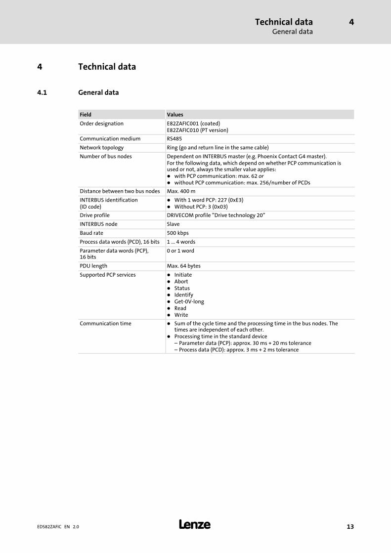
4.1 General data
Field Values
Order designation E82ZAFIC001 (coated)E82ZAFIC010 (PT version)
Communication medium RS485
Network topology Ring (go and return line in the same cable)
Number of bus nodes Dependent on INTERBUS master (e.g. Phoenix Contact G4 master).For the following data, which depend on whether PCP communication isused or not, always the smaller value applies:� with PCP communication: max. 62 or� without PCP communication: max. 256/number of PCDs
Distance between two bus nodes Max. 400 m
INTERBUS identification(ID code)
� With 1 word PCP: 227 (0xE3)� Without PCP: 3 (0x03)
Drive profile DRIVECOM profile "Drive technology 20"
INTERBUS node Slave
Baud rate 500 kbps
Process data words (PCD), 16 bits 1 ... 4 words
Parameter data words (PCP),16 bits
0 or 1 word
PDU length Max. 64 bytes
Supported PCP services � Initiate� Abort� Status� Identify� Get−0V−long� Read� Write
Communication time � Sum of the cycle time and the processing time in the bus nodes. Thetimes are independent of each other.
� Processing time in the standard device– Parameter data (PCP): approx. 30 ms + 20 ms tolerance– Process data (PCD): approx. 3 ms + 2 ms tolerance
Technical dataOperating conditions
4
� 14 EDS82ZAFIC EN 2.0
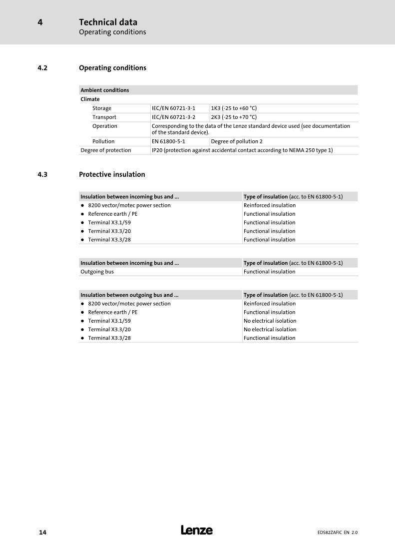
4.2 Operating conditions
Ambient conditions
Climate
Storage IEC/EN 60721−3−1 1K3 (−25 to +60 °C)
Transport IEC/EN 60721−3−2 2K3 (−25 to +70 °C)
Operation Corresponding to the data of the Lenze standard device used (see documentationof the standard device).
Pollution EN 61800−5−1 Degree of pollution 2
Degree of protection IP20 (protection against accidental contact according to NEMA 250 type 1)
4.3 Protective insulation
Insulation between incoming bus and ... Type of insulation (acc. to EN 61800−5−1)
� 8200 vector/motec power section Reinforced insulation
� Reference earth / PE Functional insulation
� Terminal X3.1/59 Functional insulation
� Terminal X3.3/20 Functional insulation
� Terminal X3.3/28 Functional insulation
Insulation between incoming bus and ... Type of insulation (acc. to EN 61800−5−1)
Outgoing bus Functional insulation
Insulation between outgoing bus and ... Type of insulation (acc. to EN 61800−5−1)
� 8200 vector/motec power section Reinforced insulation
� Reference earth / PE Functional insulation
� Terminal X3.1/59 No electrical isolation
� Terminal X3.3/20 No electrical isolation
� Terminal X3.3/28 Functional insulation

Technical dataConnection terminals
4
� 15EDS82ZAFIC EN 2.0
4.4 Connection terminals
TerminalX3.1/
Designation Function / level
59 External voltage supply of the function module� U = 24 V DC (21.6 V − 0% ... 26.4 V + 0 %)� Current consumption for 24 V DC: I = 90 mAIf the supply voltage is looped through to other bus nodes via terminal 59,the current flowing must not exceed 3 A.
7 GND1 Reference potential for terminal X3.3/20
TerminalX3.2/
Designation Function / level
7 GND1 Reference potential for terminal X3.3/20
39 GND2 Reference potential for controller inhibit (CINH) on terminal X3.3/28
TerminalX3.3/
Designation Function / level
A /DO1
RS485 data line (incoming)B DO1
C /DI1
D DI1
E GND3 Reference potential for incoming data line
F /DO2
RS485 data line (outgoing)G DO2
H /DI2
J DI2
K GND1 Reference potential for outgoing data line
� Additional HF shield termination
28 CINH Controller inhibit� Input resistance: 3.3 k�� Start = HIGH (+12 ... +30 V DC)� Stop = LOW (0 ... +3 V DC)
20 DC voltage source for internal supply of controller inhibit (CINH)� +20 V DC (reference: GND1)� Imax = 10 mA

Technical dataCommunication timeCycle time
4
� 16 EDS82ZAFIC EN 2.0
4.5 Communication time
4.5.1 Cycle time
The cycle time of the communication system is the time required to exchange all processdata between the INTERBUS master and the nodes.
It depends on the data of the communication system and can be calculated e. �g. for a baudrate of 500 kbps as follows:
tzykl � 3.35 � 10�3�(n� 48� 3�BK)� 0.24�L� 0.2
tcycl Cycle time [ms]n Sum of all data bits in the INTERBUS ringBT Number of bus terminalsL Length of the remote bus cable [km]
The following diagram shows the relationship between the cycle time and the number ofconnected bus nodes. The given values refer to the connection of Lenze controllers(e. �g. 82xx) with 48 bits (1 parameter data word + 2 process data words.
12
10
8
6
4
2
10 20 30 40 50 60
Cycle time[ms]
Number of bus nodes
1
Fig. 4−1 Relationship between cycle time and number of bus nodes
4.5.2 Processing time 8200�vector / 8200 motec
The processing time in the controller is added to the INTERBUS transmission time or cycletime.
There are no dependencies between parameter data and process data.
ƒ Parameter data (PCP): approx. 30 ms + 20 ms tolerance
ƒ Process data (PCD): approx. 3 ms + 2 ms tolerance

Technical dataDimensions
Processing time 8200�vector / 8200 motec
4
� 17EDS82ZAFIC EN 2.0
4.6 Dimensions
E82ZAFIC001function module
E82ZAFI004B
Function module E82ZAFIC010 (PT version)
E82ZAFI014B
InstallationMechanical installation
5
� 18 EDS82ZAFIC EN 2.0
5 Installation
� Danger!
Inappropriate handling of the function module and the standard device cancause serious injuries to persons and damage to material assets.
Observe the safety instructions and residual hazards included in thedocumentation of the standard device.
� Stop!
The device contains components that can be destroyed by electrostaticdischarge!
Before working on the device, the personnel must ensure that they are free ofelectrostatic charge by using appropriate measures.
5.1 Mechanical installation
Follow the notes given in the Mounting Instructions for the standard device for themechanical installation of the function module.
The Mounting Instructions for the standard device ...
ƒ are part of the scope of supply and are enclosed with each device.
ƒ provide tips to avoid damage provide tips to avoid damage through improperhandling.
ƒ describe the obligatory order of installation steps.

InstallationElectrical installation
Wiring according to EMC (CE−typical drive system)
5
� 19EDS82ZAFIC EN 2.0
5.2 Electrical installation
5.2.1 Wiring according to EMC (CE−typical drive system)
For wiring according to EMC requirements observe the following points:
� Note!
ƒ Separate control cables/data lines from motor cables.
ƒ Connect the shields of control cables/data lines at both ends in the case ofdigital signals.
ƒ Use an equalizing conductor with a cross−section of at least 16�mm2
(reference:�PE) to avoid potential differences between the bus nodes.
ƒ Observe the other notes concerning EMC−compliant wiring given in thedocumentation for the standard device.
Wiring procedure
1. Observe the bus topology, do not use any stubs.
2. Follow the wiring notes given in the documentation for the control system.
3. Only use cables which comply with the specifications listed ( 20).
4. Observe the notes concerning the voltage supply of the function module ( 21).

InstallationElectrical installationWiring with a host (master)
5
� 20 EDS82ZAFIC EN 2.0
5.2.2 Wiring with a host (master)
GG
+
E82ZAFICxxx
GG
+
E82ZAFICxxx
GG
+
E82ZAFICxxx
400 m 400 m
1
2 2 2
3 3 3
E82ZAFI008
No. Element Description
1 Host E.g. PC or PLC with INTERBUS master interface module
2 Bus cable Connects the INTERBUS master interface module to the function modules.
3 INTERBUS slave Applicable standard device (� 10) with function module.� Set DIP switch S1 ( � 29):
– Setting for the last node = OFF– Setting for all other nodes = ON
Specification of the transmission cable
General characteristics
Cable type Sold by the meter,(e.g. PHOENIX CONTACT: IBS RBC Meter−T, Order No. 28 06 28 6)
Number of conductors 3 × 2, twisted pairs, with shared shield
Conductor cross−section > 0.2 mm2
DC cable resistance < 96 �/km
Impedance (characteristic) � 120 � � 20 % (f = 64 kHz)� 100 � �15 � (f > 1 MHz)
Capacitance per unit length < 60 nF/km (f = 800 Hz)
InstallationElectrical installation
Voltage supply
5
� 21EDS82ZAFIC EN 2.0
5.2.3 Voltage supply
Internal DC voltage supply
The internal voltage ...
ƒ supplies the controller inhibit (CINH).
ƒ is available at terminal X3.3/20.
External voltage supply
� Note!
Always use a separate power supply unit in every control cabinet and safelyseparate it according to EN 61800−5−1 ("SELV"/"PELV") in the case of externalvoltage supply and larger distances between the control cabinets.
External voltage supply of the communication module is required if communication viathe fieldbus is to be maintained even when the power supply of the standard device fails.
� Note!
With external voltage supply of the function module, the active busterminating resistor is fed independently of the operation of the standarddevice. In this way, the bus system remains active even when the standarddevice is switched off or fails.
InstallationElectrical installationVoltage supply
5
� 22 EDS82ZAFIC EN 2.0
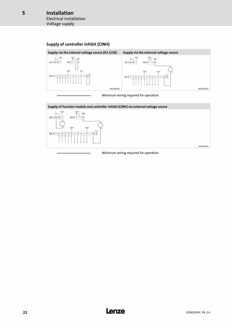
Supply of controller inhibit (CINH)
Supply via the internal voltage source (X3.3/20) Supply via the external voltage sourceGND1GND1
GND3 GND1
75959
+20V
39
A B C D E F G H J K �� 28 20
77
GND2
X3.1 X3.2
X3.3
_
+
GND1GND1
75959
+20V
39
A B C D E F G H J K �� 28 20
77
GND2
X3.1 X3.2
X3.3
GND3 GND1
E82ZAFI001 E82ZAFI002
Minimum wiring required for operation
Supply of function module and controller inhibit (CINH) via external voltage source
__
++
GND1GND1
75959
+20V
39
A B C D E F G H J K � 28 20
77
GND2
X3.1 X3.2
X3.3
GND3 GND1
�
E82ZAFI003
Minimum wiring required for operation
InstallationElectrical installationTerminal assignment
5
� 23EDS82ZAFIC EN 2.0
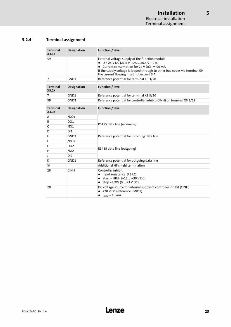
5.2.4 Terminal assignment
TerminalX3.1/
Designation Function / level
59 External voltage supply of the function module� U = 24 V DC (21.6 V − 0% ... 26.4 V + 0 %)� Current consumption for 24 V DC: I = 90 mAIf the supply voltage is looped through to other bus nodes via terminal 59,the current flowing must not exceed 3 A.
7 GND1 Reference potential for terminal X3.3/20
TerminalX3.2/
Designation Function / level
7 GND1 Reference potential for terminal X3.3/20
39 GND2 Reference potential for controller inhibit (CINH) on terminal X3.3/28
TerminalX3.3/
Designation Function / level
A /DO1
RS485 data line (incoming)B DO1
C /DI1
D DI1
E GND3 Reference potential for incoming data line
F /DO2
RS485 data line (outgoing)G DO2
H /DI2
J DI2
K GND1 Reference potential for outgoing data line
� Additional HF shield termination
28 CINH Controller inhibit� Input resistance: 3.3 k�� Start = HIGH (+12 ... +30 V DC)� Stop = LOW (0 ... +3 V DC)
20 DC voltage source for internal supply of controller inhibit (CINH)� +20 V DC (reference: GND1)� Imax = 10 mA
InstallationElectrical installationCable cross−sections and screw−tightening torques
5
� 24 EDS82ZAFIC EN 2.0
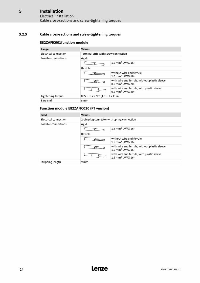
5.2.5 Cable cross−sections and screw−tightening torques
E82ZAFIC001function module
Range Values
Electrical connection Terminal strip with screw connection
Possible connections rigid:
1.5 mm2 (AWG 16)
flexible:
without wire end ferrule1.0 mm2 (AWG 18)
with wire end ferrule, without plastic sleeve0.5 mm2 (AWG 20)
with wire end ferrule, with plastic sleeve0.5 mm2 (AWG 20)
Tightening torque 0.22 ... 0.25 Nm (1.9 ... 2.2 lb−in)
Bare end 5 mm
Function module E82ZAFIC010 (PT version)
Field Values
Electrical connection 2−pin plug connector with spring connection
Possible connections rigid:
1.5 mm2 (AWG 16)
flexible:
without wire end ferrule1.5 mm2 (AWG 16)
with wire end ferrule, without plastic sleeve1.5 mm2 (AWG 16)
with wire end ferrule, with plastic sleeve1.5 mm2 (AWG 16)
Stripping length 9 mm
InstallationElectrical installation
Use of plug connectors
5
� 25EDS82ZAFIC EN 2.0
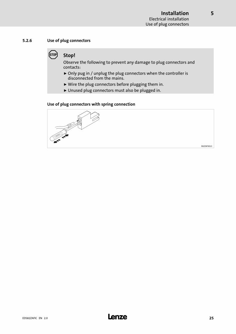
5.2.6 Use of plug connectors
� Stop!
Observe the following to prevent any damage to plug connectors andcontacts:
ƒ Only pug in / unplug the plug connectors when the controller isdisconnected from the mains.
ƒ Wire the plug connectors before plugging them in.
ƒ Unused plug connectors must also be plugged in.
Use of plug connectors with spring connection
E82ZAFX013
CommissioningBefore switching on
6
� 26 EDS82ZAFIC EN 2.0
6 Commissioning
6.1 Before switching on
� Stop!
Before you switch on the standard device and the plugged−in function modulefor the first time, check ...
ƒ the entire wiring for completeness, short circuit and earth fault.
ƒ the setting of the DIP switch S1 ( 29):– Setting for the last node = OFF– Setting for all other nodes = ON
CommissioningCommissioning steps
6
� 27EDS82ZAFIC EN 2.0
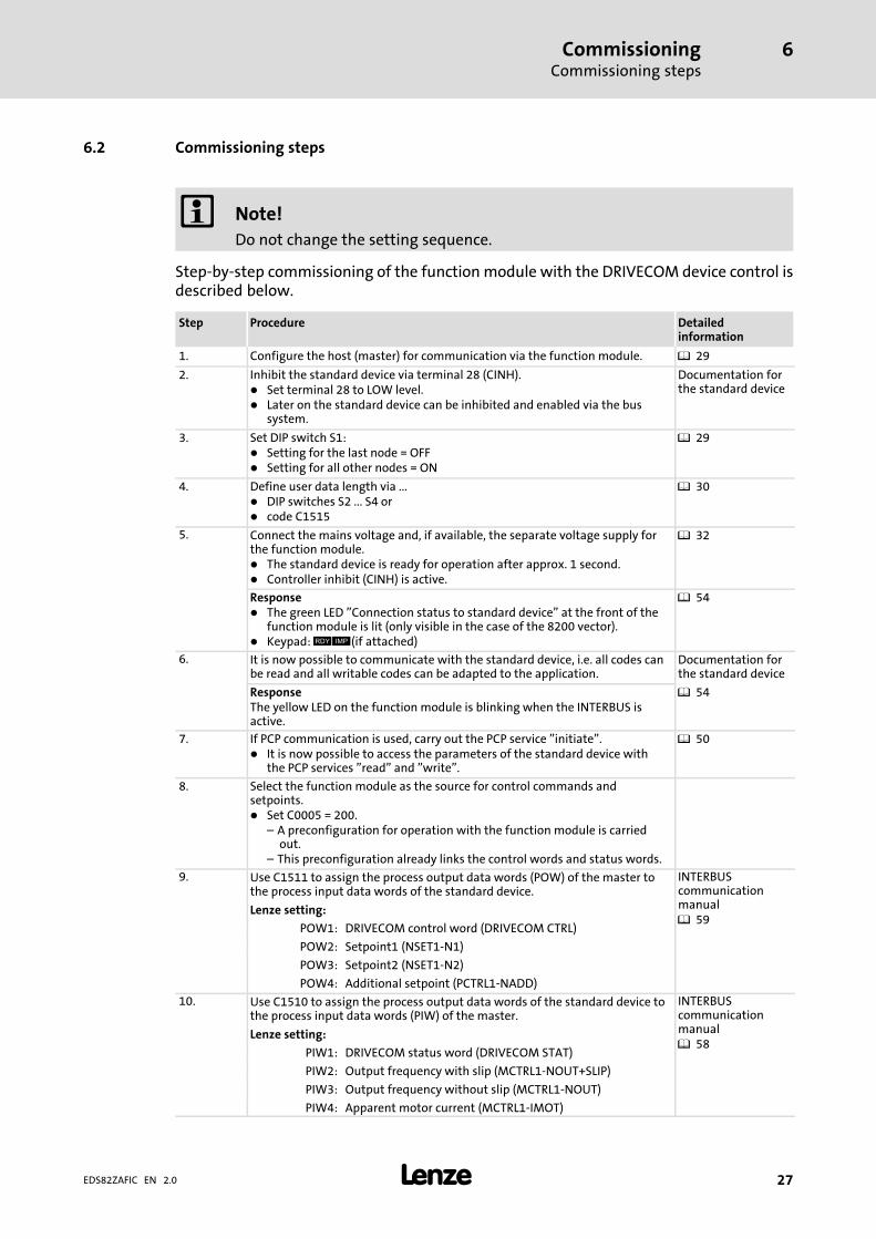
6.2 Commissioning steps
� Note!
Do not change the setting sequence.
Step−by−step commissioning of the function module with the DRIVECOM device control isdescribed below.
Step Procedure Detailedinformation
1. Configure the host (master) for communication via the function module. � 29
2. Inhibit the standard device via terminal 28 (CINH).� Set terminal 28 to LOW level.� Later on the standard device can be inhibited and enabled via the bus
system.
Documentation forthe standard device
3. Set DIP switch S1:� Setting for the last node = OFF� Setting for all other nodes = ON
� 29
4. Define user data length via ...� DIP switches S2 ... S4 or� code C1515
� 30
5. Connect the mains voltage and, if available, the separate voltage supply forthe function module.� The standard device is ready for operation after approx. 1 second.� Controller inhibit (CINH) is active.
� 32
Response� The green LED "Connection status to standard device" at the front of the
function module is lit (only visible in the case of the 8200 vector).� Keypad: � (if attached)
� 54
6. It is now possible to communicate with the standard device, i.e. all codes canbe read and all writable codes can be adapted to the application.
Documentation forthe standard device
ResponseThe yellow LED on the function module is blinking when the INTERBUS isactive.
� 54
7. If PCP communication is used, carry out the PCP service "initiate".� It is now possible to access the parameters of the standard device with
the PCP services "read" and "write".
� 50
8. Select the function module as the source for control commands andsetpoints.� Set C0005 = 200.
– A preconfiguration for operation with the function module is carriedout.
– This preconfiguration already links the control words and status words.
9. Use C1511 to assign the process output data words (POW) of the master tothe process input data words of the standard device.
INTERBUScommunicationmanual� 59
Lenze setting:
POW1: DRIVECOM control word (DRIVECOM CTRL)
POW2: Setpoint1 (NSET1−N1)
POW3: Setpoint2 (NSET1−N2)
POW4: Additional setpoint (PCTRL1−NADD)
10. Use C1510 to assign the process output data words of the standard device tothe process input data words (PIW) of the master.
INTERBUScommunicationmanual� 58
Lenze setting:
PIW1: DRIVECOM status word (DRIVECOM STAT)
PIW2: Output frequency with slip (MCTRL1−NOUT+SLIP)
PIW3: Output frequency without slip (MCTRL1−NOUT)
PIW4: Apparent motor current (MCTRL1−IMOT)
CommissioningCommissioning steps
6
� 28 EDS82ZAFIC EN 2.0
Detailedinformation
ProcedureStep
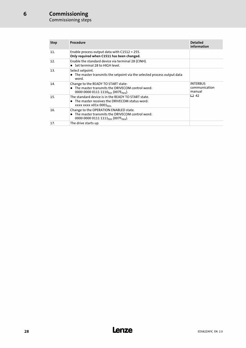
11. Enable process output data with C1512 = 255.Only required when C1511 has been changed.
12. Enable the standard device via terminal 28 (CINH).� Set terminal 28 to HIGH level.
13. Select setpoint.� The master transmits the setpoint via the selected process output data
word.
14. Change to the READY TO START state:� The master transmits the DRIVECOM control word:
0000 0000 0111 1110bin (007Ehex).
INTERBUScommunicationmanual� 4215. The standard device is in the READY TO START state.
� The master receives the DRIVECOM status word:xxxx xxxx x01x 0001bin.
16. Change to the OPERATION ENABLED state.� The master transmits the DRIVECOM control word:
0000 0000 0111 1111bin (007Fhex).
17. The drive starts up.
CommissioningConfiguring Host (master)
6
� 29EDS82ZAFIC EN 2.0
6.3 Configuring Host (master)
For communication via the function module, first the host (master) must be configured.
Master settings
The configuration of the INTERBUS requires the device description file (EDS file) for thecommunication module to be imported to the master configuration software.
The EDS file can be downloaded in the download area on http://www.Lenze.com.
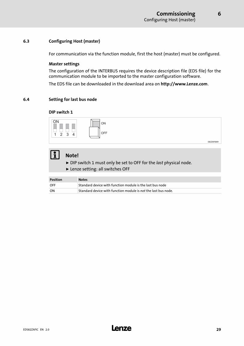
6.4 Setting for last bus node
DIP switch 1
ON
OFF1
ON
2 3 4
E82ZAFI009
� Note!
ƒ DIP switch 1 must only be set to OFF for the last physical node.
ƒ Lenze setting: all switches OFF
Position Notes
OFF Standard device with function module is the last bus node
ON Standard device with function module is not the last bus node.
CommissioningDefining the user data length
6
� 30 EDS82ZAFIC EN 2.0
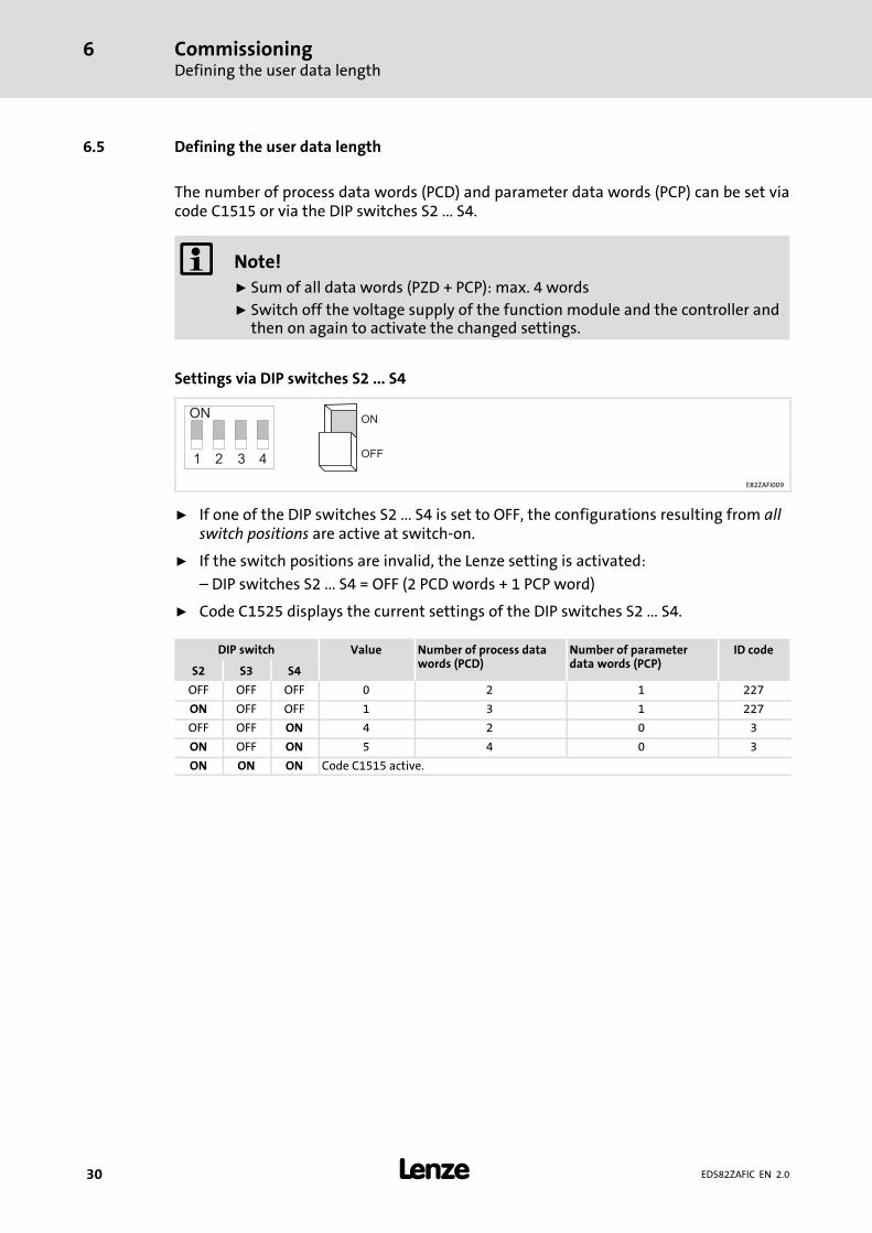
6.5 Defining the user data length
The number of process data words (PCD) and parameter data words (PCP) can be set viacode C1515 or via the DIP switches S2 ... S4.
� Note!
ƒ Sum of all data words (PZD + PCP): max. 4 words
ƒ Switch off the voltage supply of the function module and the controller andthen on again to activate the changed settings.
Settings via DIP switches S2 ... S4
ON
OFF1
ON
2 3 4
E82ZAFI009
ƒ If one of the DIP switches S2 ... S4 is set to OFF, the configurations resulting from allswitch positions are active at switch−on.
ƒ If the switch positions are invalid, the Lenze setting is activated:
– DIP switches S2 ... S4 = OFF (2 PCD words + 1 PCP word)
ƒ Code C1525 displays the current settings of the DIP switches S2 ... S4.
DIP switch Value Number of process datawords (PCD)
Number of parameterdata words (PCP)
ID code
S2 S3 S4
OFF OFF OFF 0 2 1 227
ON OFF OFF 1 3 1 227
OFF OFF ON 4 2 0 3
ON OFF ON 5 4 0 3
ON ON ON Code C1515 active.

CommissioningDefining the user data length
6
� 31EDS82ZAFIC EN 2.0
Settings via code
ƒ DIP switches S2 ... S4 = ON
ƒ Set the number of data words (PCD + PCP) via C1515.
Code
C1515Name
Process/parameter data specificationIndex
0x5A14 (23060)
Subcode Lenze Values Access Data type
− 0 0, 1, 4, 5 rw FIX32
11 ... 14
21 ... 23
Values Description
0, 1, 4, 5 The configuration resulting from the values corresponding to the set DIP switchpositions becomes active.
11 ... 14 � No PCP� 11 (1 word PCD) ... 14 (4 words PCD)
21 ... 23 � 1 word PCP� 21 (1 word PCD) ... 23 (3 words PCD)

CommissioningConnecting the mains voltage
6
� 32 EDS82ZAFIC EN 2.0
6.6 Connecting the mains voltage
� Note!
If the external voltage supply of the function module is used, switch it on aswell.
ƒ The standard device is ready for operation approx. 1 s after switching on the supplyvoltage.
ƒ The controller inhibit is active.
ƒ The green LED at the front of the function module is lit.
Protection against uncontrolled start−up
� Note!
Establishing communication
For establishing communication via an externally supplied function module,the standard device must be switched on as well.
ƒ After communication has been established, the externally supplied moduleis independent of the power on/off state of the standard device.
Protection against uncontrolled start−up
After a fault (e.g. short−term mains failure), a restart of the drive is not alwayswanted and − in some cases − even not allowed.
The restart behaviour of the controller can be set in C0142:
ƒ C0142 = 0 (Lenze setting)– The controller remains inhibited (even if the fault is no longer active).– The drive starts in a controlled mode by explicitly enabling the controller:
LOW−HIGH edge at terminal 28 (CINH)
ƒ C0142 = 1– An uncontrolled restart of the drive is possible.

Process data transfer 7
� 33EDS82ZAFIC EN 2.0
7 Process data transfer
INTERBUS transmits two different data types between the host (master) and thecontrollers (slaves):
ƒ Parameter data
ƒ Process data
Process data
ƒ Process data is transmitted via the process data channel.
ƒ The process data serves to control the controller.
ƒ The host can directly access the process data. Data in the PLC, for instance, aredirectly stored in the I/O area.
ƒ The data exchange between the master drive and the controller is required in theshortest possible time. Here, small amounts of data can be transmitted cyclically.
ƒ Process data ...
– are not saved in the controller;
– are transmitted between the host system and the controllers in order that aconstant exchange between current input and output data takes place.
ƒ Process data are, for instance, setpoints and actual values.
Parameter data
ƒ Parameter data is transmitted via the parameter data channel (PCP channel).
ƒ The transmission of parameter data is usually not time−critical.
ƒ Parameter data are, for instance, operating parameters, motor data and diagnosticinformation.
ƒ The access to all Lenze codes and indices is permitted.
ƒ When saving parameter changes, please observe the notes regarding code C0003.
Process data transferLenze device controlProcess data transfer
7
� 34 EDS82ZAFIC EN 2.0
7.1 Lenze device control
� Note!
Deactivate the DRIVECOM device control if you want to use the Lenze devicecontrol.
For this purpose, use code C1510 / C1511.
7.1.1 Process data transfer
Process data telegrams between the host (master) and the controllers (slaves) connectedto the INTERBUS are distinguished as follows with regard to their direction:
ƒ Process data telegrams from the master
The master transmits max. 4�process output data words (POW) to the slave.
ƒ Process data telegrams to the master
The master receives max. 4�process input data words (PIW) from the slave.
Via the free configuration of the process data, assign the max. 4 process data words of theINTERBUS to the process data words of the controller. The assignments can be defined inthe codes C1511 (process output data) ad C1510 (process input data).
Process data telegram to the master
The function block to be used for the cyclic process data telegram from the drive to themaster is called AIF−OUT.
The status word (byte 1 and byte 2) contained in the process data telegram is sent to themaster via the AIF−OUT function block.
Process data telegram from the master
The function block to be used for the cyclic process data telegram from the master to thedrive is called AIF−IN.
The control word (byte 1 and byte 2) contained in the process data telegram is sent fromthe master and is received in the controller via the AIF−IN function block.
Process data transferLenze device control
Process data transfer
7
� 35EDS82ZAFIC EN 2.0
Selection of setpoint source
8200 vector / 8200�motec controller
For these controllers, the selection of the setpoint source is defined using code C0001(index: 0x5FFE). For evaluating the process data, the code C0001 has to be set to thevalue�"3" when the controller is operated with the function module. The setpoint source isprovided by the process data channel which describes the frequency setpoint (mapping toC0046) and the control word (C0135).
In C0412/x, the assignment of the setpoint source to the desired analog signal can bechecked�/�changed.
� Note!
The selection of the setpoint source (C0001) must be set identically in allparameter sets used in the controller.

Process data transferLenze device controlProcess data signals for 8200 vector / 8200 motec
7
� 36 EDS82ZAFIC EN 2.0
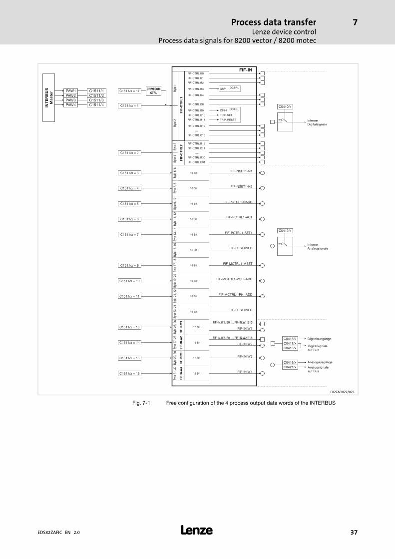
7.1.2 Process data signals for 8200 vector / 8200 motec
Configuring process output data
The assignment of the max. 4 process output data words (POW) of the master to bit controlcommands or setpoints of the controller can be configured freely using C1511.
ƒ In order to activate the DRIVECOM device control, assign the DRIVECOM controlword to a POW (C1511/x = 17).
– The DRIVECOM control word is mapped to the FIF control word 1.
– The controller conforms to the DRIVECOM state machine ( 42).
ƒ The FIF control words can be used to set up an extended Lenze device control( 38).
� Note!
When C1511 is changed, the process output data is automatically locked toensure data consistency. Use C1512 to enable single or all POWs.
Configuration of the process output data
Code
C1511Name
Configuring process output dataIndex
0x5A18 (23064)
Subcode Lenze Access Data type
1 POW1 17 DRIVECOM control word (DRIVECOM−CTRL) rw FIX32
2 POW2 3 Setpoint 1 (NSET1−N1) rw FIX32
3 POW3 4 Setpoint 2 (NSET1−N2) rw FIX32
4 PAW4 5 Additional setpoint (PCTRL1−NADD) rw FIX32
� Parameter set transfer
� Tip!
For a detailed description of the code, see � 59.
Process data transferLenze device control
Process data signals for 8200 vector / 8200 motec
7
� 37EDS82ZAFIC EN 2.0
FIF-IN
FIF
-C
TR
L1
FIF
-C
TR
L2
Byte
2By
te1
Byte
3By
te4
Byte
5,6
Byte
7,8
Byte
9,10
Byte
11,1
2By
te13
,14
Byte
15,1
6By
te17
,18
Byte
19,2
0By
te21
,22
Byte
23,2
4By
te25
,26
FIF
-IN
.W1
FIF
-IN
.W2
FIF
-IN
.W3
FIF
-IN
.W4
Byte
27,2
8By
te29
,30
Byte
31,3
2
FIF-CTRL.B0
FIF-CTRL.B1
FIF-CTRL.B2
FIF-CTRL.B4
…
FIF-CTRL.B8
FIF-CTRL.B12
…
FIF-CTRL.B15
FIF-CTRL.B16
FIF-CTRL.B17
…
FIF-CTRL.B30
FIF-CTRL.B31
16 Bit
16 Bit
16 Bit
16 Bit
16 Bit
16 Bit
16 Bit
16 Bit
16 Bit
16 Bit
16 Bit
16 Bit
16 Bit
16 Bit
FIF-NSET1-N1
InterneDigitalsignale
InterneAnalogsignale
FIF-NSET1-N2
FIF-PCTRL1-NADD
FIF-PCTRL1-SET1
FIF-PCTRL1-ACT
FIF-MCTRL1-MSET
FIF-RESERVED
FIF-MCTRL1-VOLT-ADD
FIF-MCTRL1-PHI-ADD
FIF-RESERVED
FIF-IN.W1
FIF-IN.W1. B0 … FIF-IN.W1.B15
FIF-IN.W2. B0 … FIF-IN.W2.B15
FIF-IN.W2
FIF-IN.W3
FIF-IN.W4
FIF-CTRL.B9
FIF-CTRL.B10
FIF-CTRL.B11
FIF-CTRL.B3 DCTRLQSP
CINH
TRIP-SET
TRIP-RESET
DCTRLC0410/x
200
C0412/x
C1511/x = 1
C1511/x = 2
C1511/x = 3
C1511/x = 4
C1511/x = 5
C1511/x = 6
C1511/x = 7
C1511/x = 9
C1511/x = 10
C1511/x = 11
C1511/x = 13
C1511/x = 15
C1511/x = 16
C1511/x = 14
C1511/x = 17
200
C0419/x Analogausgänge
Analogsignaleauf Bus
C0421/x
C0415/x Digitalausgänge
Digitalsignaleauf Bus
C0417/xC0418/x
DRIVECOM
CTRL
INT
ER
BU
S
Ma
ste
r
PAW2PAW1
PAW3PAW4
C1511/2C1511/1
C1511/3C1511/4
E82ZAFI022/023
Fig. 7−1 Free configuration of the 4 process output data words of the INTERBUS

Process data transferLenze device controlProcess data signals for 8200 vector / 8200 motec
7
� 38 EDS82ZAFIC EN 2.0
FIF control word 1 (FIF−CTRL1) FIF control word 2 (FIF−CTRL2)
Bit Assignment Bit Assignment
0 / 1 JOG values (NSET1−JOG2/3 | NSET1−JOG1/3) 0 Manual/remote changeover (DCTRL1−H/Re)
Bit 1 001
Not activeActive
00
01
C0046 activeJOG1 (C0037) active
1 Switch off I−component of process controller(PCTRL1−I−OFF)
11
01
JOG2 (C0038) activeJOG3 (C0039) active
01
Not activeActive
2 Current direction of rotation (DCTRL1−CW/CCW) 2 Switch off process controller (PCTRL1−OFF)
01
Not invertedInverted
01
Not activeActive
3 Quick stop (QSP) (FIF−CTRL1−QSP) 3 Reserved
Do not write to this bit!01
Not activeActive (deceleration via QSP ramp C0105)
4 Stop ramp function generator (NSET1−RFG1−STOP) 4 Stop process controller (PCTRL1−STOP)
01
Not activeActive
01
Not activeActive
5 Ramp function generator input = 0 (NSET1−RFG1−0) 5 CW rotation/quick stop (QSP) (DCTRL1−CW/QSP)
01
Not activeActive (deceleration via C0013)
01
Not activeActive
6 UP function of motor potentiometer (MPOT1−UP) 6 CCW rotation/quick stop (QSP) (DCTRL1−CCW/QSP)
01
Not activeActive
01
Not activeActive
7 DOWN function of motor potentiometer (MPOT1−DOWN) 7 X3/E1 is digital frequency input (DFIN1−ON)
01
Not activeActive
01
Not activeActive
8 Reserved 8 Reserved
9 Controller inhibit (FIF−CTRL1−CINH) 9 Reserved
01
Controller enabledController inhibited
10 External fault (FIF−CTRL1−TRIP−SET) 10 Reserved
11 Reset fault (FIF−CTRL1−TRIP−RESET) 11 Reserved
0 � 1 Bit change resets TRIP
12 / 13 Parameter set changeover(DCTRL1−PAR3/4 | DCTRL1−PAR2/4)
12 Reserved
Bit 13 12
00
01
PAR1PAR2
13 Reserved
11
01
PAR3PAR4
14 DC injection brake (MTCRL1−DCB) 14 Reserved
01
Not activeActive
15 Reserved 15 Reserved
Tab. 7−1 Parameter structure of FIF control word (FIF−CTRLx)
� Note!
Use of bit 5 and bit 6 in FIF control word 2
Set codes C0410/22 (DCTRL1−CW/QSP) and C0410/23 (DCTRL1−CCW/QSP) to"200".

Process data transferLenze device control
Process data signals for 8200 vector / 8200 motec
7
� 39EDS82ZAFIC EN 2.0
Configuring process input data
The assignment of the bit status information or actual values of the controller to the max.4 process input data words (PIW) of the master can be configured freely:
ƒ In order to access DRIVECOM−compliant status information, assign the DRIVECOMstatus word to a PIW (C1511/x = 18).
ƒ The FIF status word�1 is mapped to the DRIVECOM status word.
Configuration of the process input data
Code
C1510Name
Configuring process input dataIndex
0x5A19 (23065)
Subcode Lenze Access Data type
1 PIW1 18 DRIVECOM status word (DRIVECOM−STAT) rw FIX32
2 PIW2 3 Output frequency with slip (MCTRL1−NOUT+SLIP) rw FIX32
3 PIW3 4 Output frequency without slip (MCTRL1−NOUT) rw FIX32
4 PIW4 5 Apparent motor current (MCTRL1−IMOT) rw FIX32
� Parameter set transfer
� Tip!
For a detailed description of the code, see � 58.

Process data transferLenze device controlProcess data signals for 8200 vector / 8200 motec
7
� 40 EDS82ZAFIC EN 2.0
FIF
-S
TA
T2
FIF
-S
TA
T1
Byte4
Byte2
Byte3
Byte1Byte
9,10Byte
11,12Byte
13,14Byte
15,16Byte
17,18Byte
19,20Byte
21,22Byte
23,24
FIF-STAT.B16
FIF-STAT.B1
FIF-STAT.B17
FIF-STAT.B2
…
…
FIF-STAT.B30
FIF-STAT.B14
FIF-STAT.B31
FIF-STAT.B15
Byte5,6
Byte7,8
16 Bit
16 Bit
16 Bit
16 Bit
16 Bit
16 Bit
16 Bit
16 Bit
16 Bit
16 Bit
MCTRL1-NOUT
MCTRL1-NOUT+SLIP
MCTRL1-IMOT
PCTRL1-ACT
PCTRL1-SET
PCTRL1-OUT
MCTRL1-MOUT
MCTRL1-DCVOLT
PCTRL1-RFG1-IN
NSET1-NOUT
Byte27,28
FIF
-OU
T.W
2FIF
-OU
T.W
1FIF
-OU
T.W
3FIF
-OU
T.W
4
Byte25,26
Byte29,30
Byte31,32
16 Bit
16 Bit
16 Bit
16 Bit
STAT1.B0 FIF-OUT.W1.B0FIF-OUT.W1.B1
FIF-OUT.W1.B14FIF-OUT.W1.B15
STAT1.B1STAT1.B2STAT1.B3STAT1.B4STAT1.B5STAT1.B6STAT1.B7 …STAT1.B8STAT1.B9
STAT1.B10STAT1.B11STAT1.B12STAT1.B13STAT1.B14STAT1.B15
STAT1
C0417/1
C0417/3
C0417/5C0417/4
C0417/6
C0417/15C0417/16
DCTRL1-NOUT=0DCTRL1-CINH
DCTRL1-IMP
DCTRL1-STAT*1DCTRL1-STAT*2DCTRL1-STAT*4DCTRL1-STAT*8
DCTRL1-OH-WARNDCTRL1-OV
STAT2.B0 FIF-OUT.W2.B0STAT2.B1 FIF-OUT.W2.B1
…STAT2.B14 FIF-OUT.W2.B14STAT2.B15 FIF-OUT.W2.B15
STAT2
C0418/1C0418/2
…C0418/15C0418/16
C0421/5
C0421/4
C0421/3
C0421/6
FIF-OUT
C1510/x = 1
C1510/x = 2
C1510/x = 18
C1510/x = 3
C1510/x = 4
C1510/x = 5
C1510/x = 6
C1510/x = 7
C1510/x = 8
C1510/x = 9
C1510/x = 10
C1510/x = 11
C1510/x = 12
C1510/x = 13
C1510/x = 15
C1510/x = 16
C1510/x = 14
DRIVECOM
STAT
INT
ER
BU
S
Ma
ste
r
PEW2PEW1
PEW3PEW4
C1510/2C1510/1
C1510/3C1510/4
E82ZAFI020/021
Fig. 7−11 Free configuration of the 4 process input data words of the INTERBUS

Process data transferLenze device control
Process data signals for 8200 vector / 8200 motec
7
� 41EDS82ZAFIC EN 2.0
FIF status word 1 (FIF−STAT1) FIF status word 2 (FIF−STAT2)
Bit Assignment Bit Assignment
0 Current parameter set bit 0 (DCTRL1−PAR−B0) 0 Current parameter set bit 1 (DCTRL1−PAR−B1)
01
Parameter set 1 or 3 activeParameter set 2 or 4 active
01
Parameter set 1 or 2 activeParameter set 3 or 4 active
1 Pulse inhibit (DCTRL1−IMP) 1 TRIP, Qmin or pulse inhibit active (DCTRL1−TRIP−QMIN−IMP)
01
Power outputs enabledPower outputs inhibited
01
FalseTrue
2 Imax limit (MCTRL1−IMAX)
(If C0014 = 5: Torque setpoint)
2 PTC warning active (DCTRL1−PTC−WARN)
01
Not reachedReached
01
FalseTrue
3 Output frequency = frequency setpoint(DCTRL1−RFG1=NOUT)
3 Reserved
Do not write to this bit!
01
FalseTrue
4 Ramp function generator input 1 = ramp functiongenerator output 1 (NSET1−RFG1−I=O)
4 C0054 < C0156 and Qmin threshold reached(DCTRL1−(IMOT<ILIM)−QMIN)
01
FalseTrue
01
FalseTrue
5 Qmin threshold (PCTRL1−QMIN) 5 C0054 < C0156 and NSET1−RFG1−I=O(DCTRL1−(IMOT<ILIM)−RFG−I=O)
01
Not reachedReached
01
FalseTrue
6 Output frequency = 0 (DCTRL1−NOUT=0) 6 LP1 warning (fault in motor phase) active(DCTRL1−LP1−WARN)
01
FalseTrue
01
FalseTrue
7 Controller inhibit (DCTRL1−CINH) 7 f < fmin (NSET1−C0010 ... C0011)
01
Controller enabledController inhibited
01
FalseTrue
11...8 Device status (DCTRL1−STAT*1 ... STAT*8) 8 TRIP active (DCTRL1−TRIP)
Bit 11 10 9 801
FalseTrue
00
00
01
00
Controller initialisationSwitch−on inhibit
9 Motor is running (DCTRL1−RUN)
00
01
10
10
Operation inhibitedFlying−restart circuit active
01
FalseTrue
0 1 0 1 DC−injection brake active 10 Motor is running clockwise (DCTRL1−RUN−CW)
00
11
11
01
Operation enabledMessage active
01
FalseTrue
1 0 0 0 Fault active 11 Motor is running counter−clockwise (DCTRL1−RUN−CCW)
1 1 1 1 Communication with basic device notpossible
01
FalseTrue
12 Overtemperature warning (DCTRL1−OH−WARN) 12 Reserved
01
No warning�max − 10 °C reached
13 DC−bus overvoltage (DCTRL1−OV) 13 Reserved
01
No overvoltageOvervoltage
14 Direction of rotation (DCTRL1−CCW) 14 C0054 > C0156 and NSET1−RFG1−I=0(DCTRL1−(IMOT>ILIM)−RFG−I=O)
01
CW rotationCCW rotation
01
FalseTrue
15 Ready for operation (DCTRL1−RDY) 15 Reserved
01
Not ready for operation (fault)Ready for operation (no fault)
Tab. 7−2 Parameter structure FIF status word (FIF−STATx)

Process data transferDRIVECOM controlDRIVECOM state machine
7
� 42 EDS82ZAFIC EN 2.0
7.2 DRIVECOM control
7.2.1 DRIVECOM state machine
The control information is provided by the function module via the control word.
ƒ The controllers have standardised device states according to DRIVECOM Profile 20.
ƒ Information on the current device status is stored in the DRIVECOM parameter"status word".
ƒ Commands in the DRIVECOM parameter "control word" can change the devicestatus. These commands are represented by arrows in the following diagram.
Inhibit voltagexxxx xxxx xxxx xx0x
Automatically when fault reaction is completed
Standstillxxxx xxxx xxxx x110
Standstillxxxx xxxx xxxxx110
Switch onxxxx xxxx xxxx x111
Automatically wheninitialisation iscompleted
Reset faultxxxx xxxx 0xxx xxxx
Switch on device
Status word xxxx xxxx x0xx 0000
NOT READY TO SWITCH ON
READY TO SWITCH ONStatus word xxxx xxxx x01x 0001
SWITCHED ON
Status word xxxx xxxx x01x 0011
OPERATION ENABLEDStatus word xxxx xxxx x01x 0111
FAULTStatus word xxxx xxxx x0xx 1000
SWITCH−ON INHIBIT
Status word xxxx xxxx x0xx 0000
QUICK STOP ACTIVEStatus word xxxx xxxx x01x 0111
Enable operationxxxx xxxx xxxx 1111 andact. speed value <> 0*
Inhibit operationxxxx xxxx xxxx 0111 oract. speed value = 0 *
Inhibit RFG is mapped toquick stop
Quick stopxxxx xxxx xxxx x01x
Quick stopxxxx xxxx xxxx x01x
Inhibit voltagexxxx xxxx xxxx xx0x
Standstillxxxx xxxx xxxx x110
FAULT REACTION ACTIVE
Status word xxxx xxxx x0xx 1111
Fault recognised
xxxx xxxx 1xxx xxxx
Inhibit voltagexxxx xxxx xxxx xx01or
quick stop completed
9
8
4 5
11
6
7
1012
14
13
3
2
Fig. 7−2 Status diagram� of DRIVECOM device control
* only effective for 821X, 8200 vector when the automatic DC injection brake is active (C0106,C2106 <> 0)
Process data transferDRIVECOM control
DRIVECOM control word
7
� 43EDS82ZAFIC EN 2.0
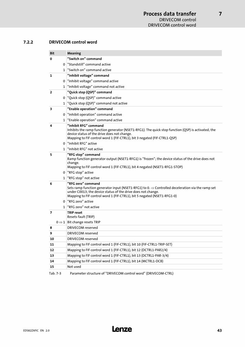
7.2.2 DRIVECOM control word
Bit Meaning
0 "Switch on" command
0 "Standstill" command active
1 "Switch on" command active
1 "Inhibit voltage" command
0 "Inhibit voltage" command active
1 "Inhibit voltage" command not active
2 "Quick stop (QSP)" command
0 "Quick stop (QSP)" command active
1 "Quick stop (QSP)" command not active
3 "Enable operation" command
0 "Inhibit operation" command active
1 "Enable operation" command active
4 "Inhibit RFG" commandInhibits the ramp function generator (NSET1−RFG1). The quick stop function (QSP) is activated; thedevice status of the drive does not change.Mapping to FIF control word 1 (FIF−CTRL1), bit 3 negated (FIF−CTRL1−QSP)
0 "Inhibit RFG" active
1 "Inhibit RFG" not active
5 "RFG stop" commandRamp function generator output (NSET1−RFG1) is "frozen"; the device status of the drive does notchange.Mapping to FIF control word 1 (FIF−CTRL1), bit 4 negated (NSET1−RFG1−STOP)
0 "RFG stop" active
1 "RFG stop" not active
6 "RFG zero" commandSets ramp function generator input (NSET1−RFG1) to 0. � Controlled deceleration via the ramp setunder C0013; the device status of the drive does not change.Mapping to FIF control word 1 (FIF−CTRL1), bit 5 negated (NSET1−RFG1−0)
0 "RFG zero" active
1 "RFG zero" not active
7 TRIP resetResets fault (TRIP)
0 � 1 Bit change resets TRIP
8 DRIVECOM reserved
9 DRIVECOM reserved
10 DRIVECOM reserved
11 Mapping to FIF control word 1 (FIF−CTRL1), bit 10 (FIF−CTRL1−TRIP−SET)
12 Mapping to FIF control word 1 (FIF−CTRL1), bit 12 (DCTRL1−PAR2/4)
13 Mapping to FIF control word 1 (FIF−CTRL1), bit 13 (DCTRL1−PAR−3/4)
14 Mapping to FIF control word 1 (FIF−CTRL1), bit 14 (MCTRL1−DCB)
15 Not used
Tab. 7−3 Parameter structure of "DRIVECOM control word" (DRIVECOM−CTRL)

Process data transferDRIVECOM controlDRIVECOM status word
7
� 44 EDS82ZAFIC EN 2.0
7.2.3 DRIVECOM status word
Bit Meaning
0 Device status "Ready to switch on"
01
Status less than "Ready to switch on"Status at least "Ready to switch on"
1 Device status "Switched on"
01
Status less than "Switched on"Status at least "Switched on"
2 Device status "Operation enabled"
01
Status less than "Operation enabled"Status "Operation enabled"
3 Device status "Fault"
01
No fault (TRIP)Fault (TRIP) active
4 Status "Inhibit voltage" command
01
Command appliedCommand not applied
5 Status "Quick stop (QSP)" command
01
Command appliedCommand not applied
6 Device status "Switch−on inhibit"
01
Status "Switch−on inhibit" not activeStatus "Switch−on inhibit" active
7 Collective warning
01
No warningWarning (overtemperature) active
8 Collective messageAutomatic setting and resetting of pulse inhibit (IMP) in the device status "Operation enabled".Possible causes: Undervoltage, overvoltage or overcurrent
01
No messageMessage IMP active
9 Bus access right
1 Always
10 Status speed/frequency deviation
01
RFGon �� RFGoffRFGon = RFGoff
110
Status DRIVECOM speed limitationAlways
12 Mapping of FIF status word 1 (FIF−STAT1), bit 0 (DCTRL1−PAR−B0)
13 Mapping of FIF status word 2 (FIFSTAT2), bit 0 (DCTRL1−PAR−B1)
14 Mapping of FIF status word 1 (FIFSTAT1), bit 2 (MCTRL1−IMAX)
15 Mapping of FIF status word 1 (FIF−STAT1), bit 5 (PCTRL1−QMIN)
Process data transferDRIVECOM control
Bit control commands
7
� 45EDS82ZAFIC EN 2.0
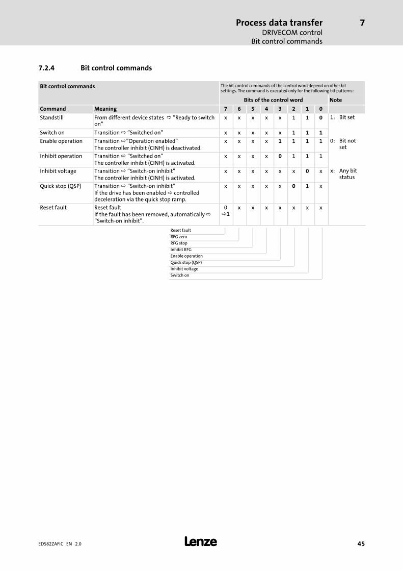
7.2.4 Bit control commands
Bit control commands The bit control commands of the control word depend on other bitsettings. The command is executed only for the following bit patterns:
Bits of the control word Note
Command Meaning 7 6 5 4 3 2 1 0
Standstill From different device states � "Ready to switchon"
x x x x x 1 1 0 1: Bit set
Switch on Transition � "Switched on" x x x x x 1 1 1
Enable operation Transition �"Operation enabled"The controller inhibit (CINH) is deactivated.
x x x x 1 1 1 1 0: Bit notset
Inhibit operation Transition � "Switched on"The controller inhibit (CINH) is activated.
x x x x 0 1 1 1
Inhibit voltage Transition � "Switch−on inhibit"The controller inhibit (CINH) is activated.
x x x x x x 0 x x: Any bitstatus
Quick stop (QSP) Transition � "Switch−on inhibit"If the drive has been enabled � controlleddeceleration via the quick stop ramp.
x x x x x 0 1 x
Reset fault Reset faultIf the fault has been removed, automatically �"Switch−on inhibit".
0�1
x x x x x x x
Reset fault
RFG zero
RFG stop
Inhibit RFG
Enable operation
Quick stop (QSP)
Inhibit voltage
Switch on

Process data transferDRIVECOM controlStatus bits
7
� 46 EDS82ZAFIC EN 2.0
7.2.5 Status bits
Status bits The current device status is unambiguously coded in the bits 0 ... 6 ofthe status word:
Bits of the status word Note
Device status Meaning 6 5 4 3 2 1 0
Not ready to switchon
Controller is being initialised and is not yet readyto operate.After initialisation automatically � "Ready toswitch on"
0 x x 0 0 0 0 1 Bit set
Switch−on inhibit Controller inhibited (CINH).Waiting for "Standstill" command
1 x x 0 0 0 0
Ready to switch on Controller inhibited (CINH).Waiting for "Switch−on" command
0 1 x 0 0 0 1 0 Bit notset
Switched on Controller inhibited (CINH).Waiting for "Operation enabled" command.
0 1 x 0 0 1 1
Operation enabled Controller enabled (CINH).Pulse inhibit can be set automatically
0 1 x 0 1 1 1 x Any bitstatus
Fault reaction active Fault (TRIP) recognised, a time−based,fault−dependent reaction is executed.Then automatically � "Fault"
0 x x 1 1 1 1
Fault Controller is in the device status "Fault". 0 x x 1 0 0 0
Quick stop (QSP)active
"Quick stop (QSP)" command has been sent in thedevice status "Operation enabled" � controlleddeceleration via the quick stop ramp.After deceleration automatically � "Switch−oninhibit"
0 0 x 0 1 1 1
Switch−on inhibit
Quick stop (QSP)
Inhibit voltage
Fault
Operation enabled
Switched on
Ready to switch on

Parameter data transferConfigure parameter data channel (PCP communication)
8
� 47EDS82ZAFIC EN 2.0
8 Parameter data transfer
8.1 Configure parameter data channel (PCP communication)
Access to the codes of the controller
The parameter data channel (PCP) ...
ƒ enables parameter setting and diagnostics of the controller;
ƒ permits access to Lenze parameters (codes);
ƒ is built up identically for both transfer directions.
The parameter data is addressed via codes that can be found listed in a code table in thedocumentation of the controller.
The drive parameters to be changed are included in the Lenze controllers as codes.
The codes of the controller are addressed by the index while being accessed via thefunction/communication module.
The index for Lenze code numbers is within 16576 (0x40C0) and 24575 (0x5FFF).
Conversion formula:
Index[dez] � 24575 � Lenze−Codestellennummer
Example for code C0001 (operating mode):
Decimal notation Hexadecimal notation
Index = 24575 − LENZE CODE NO Indexhex = 0x5FFF − LENZE CODE NOhex
Index = 24574 (= 24575 − 1) Indexhex = 0x5FFE (= 0x5FFF − 1)
Value range of the Lenze parameters
The value range of the Lenze codes can be obtained from the "Code table" in thedocumentation of the controller.
The data of the Lenze parameters is mainly represented in a fixed point format ofINTEGER32 data type with four decimal decimal positions. This means that the parametervalue from the documentation has to be multiplied by 10000.
Example for code C0039 (JOG) = 150.4 Hz
Parameter value multiplied by factor: 150.4 x 10000 =
ƒ 1504000 (decimal notation)
ƒ 0x0016F300 (hexadecimal notation)
Parameter data transferConfigure parameter data channel (PCP communication)Parameter sets for 8200 vector controller
8
� 48 EDS82ZAFIC EN 2.0
8.1.1 Parameter sets for 8200 vector controller
The 8200 vector controller has four parameter sets the parameters of which can be directlyaddressed via the INTERBUS.
Addressing
Addressing is carried out with a code offset:
ƒ Offset "0" addresses the parameter set 1 with the codes C0000 ... C1999.
ƒ Offset "2000" addresses the parameter set 2 with the codes C2000 ... C3999.
ƒ Offset "4000" addresses the parameter set 3 with the codes C4000 ... C5999.
ƒ Offset "6000" addresses the parameter set 4 with the codes C6000 ... C7999.
If a parameter is only available once (see documentation of the controller), use the codeoffset "0".
Example
Addressing of the code C0011 (maximum field frequency) in different parameter sets:
ƒ C0011 in parameter set 1: Code no. = 11
ƒ C0011 in parameter set 2: Code no. = 2011
ƒ C0011 in parameter set 3: Code no. = 4011
ƒ C0011 in parameter set 4: Code no. = 6011
� Note!
Automatic saving of the changed parameter data is activated (Lenze basicsetting, can be switched off via C0003).

Parameter data transferInitialise PCP communication
CRL entries
8
� 49EDS82ZAFIC EN 2.0
8.2 Initialise PCP communication
8.2.1 CRL entries
In order that communication between the host (master) and the function/communicationmodule can take place, the following entries in the communication relation list (CRL) of themaster have to be set:
Field name Entry
Communication reference 2
Connection type Master/slave acyclic
Connection attribute Defined
Max−PDU Sending−High−Prio 0
Max−PDU Sending−Low−Prio 64
Max−PDU Receiving−High−Prio 0
Max−PDU Receiving−Low−Prio 64
Supported Services Request 0x80�30�00
Supported Services Response 0x00�00�00
Maximum SCC 1
Maximum RCC 1
Maximum SAC 1
Maximum RAC 1
8.2.2 Available PCP services
The PCP services (PCP = Peripherals Communication Protocol) serve to transmitparameters via the PCP channel.
Lenze controllers support the following PCP services:
ƒ "Initiate": Establishing connection from the master to the controller ( 50)
ƒ "Abort": Aborting connection ( 50)
ƒ "Read": Reading parameters ( 51)
ƒ "Write": Writing parameters ( 51)
ƒ "Get−OD": Reading out the object directory (OD) ( 51)
ƒ "Identify": Identification of the controller ( 52)
ƒ "Status": Reading the status of the controller ( 53)
In the following, only those parameters and their contents are shown which are returnedby the Lenze controllers. All other transfer parameters of the given PCP services can beobtained from the corresponding descriptions of the master.

Parameter data transferInitialise PCP communicationAvailable PCP services
8
� 50 EDS82ZAFIC EN 2.0
Initiate
The "Initiate" PCP service establishes a logic connection between the master and thefunction/communication module. The controller provides the following parameters:
Designation Value Meaning
Profile number 0x21 DRIVECOM profile of version 1
Password 0 Password function of INTERBUS is not supported.
Access groups 0 No access groups exist.
Access protection supported TRUE Access protection is supported.
OD version 0 Version of the object directory
Abort
The "Abort" PCP service aborts a logic connection between the master and thefunction/communication module.
Parameter data transferInitialise PCP communication
Available PCP services
8
� 51EDS82ZAFIC EN 2.0
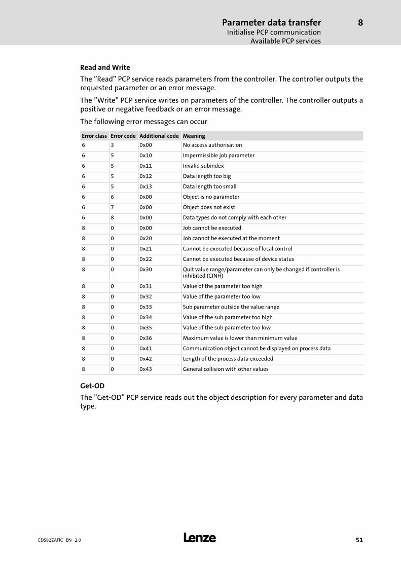
Read and Write
The "Read" PCP service reads parameters from the controller. The controller outputs therequested parameter or an error message.
The "Write" PCP service writes on parameters of the controller. The controller outputs apositive or negative feedback or an error message.
The following error messages can occur
Error class Error code Additional code Meaning
6 3 0x00 No access authorisation
6 5 0x10 Impermissible job parameter
6 5 0x11 Invalid subindex
6 5 0x12 Data length too big
6 5 0x13 Data length too small
6 6 0x00 Object is no parameter
6 7 0x00 Object does not exist
6 8 0x00 Data types do not comply with each other
8 0 0x00 Job cannot be executed
8 0 0x20 Job cannot be executed at the moment
8 0 0x21 Cannot be executed because of local control
8 0 0x22 Cannot be executed because of device status
8 0 0x30 Quit value range/parameter can only be changed if controller isinhibited (CINH)
8 0 0x31 Value of the parameter too high
8 0 0x32 Value of the parameter too low
8 0 0x33 Sub parameter outside the value range
8 0 0x34 Value of the sub parameter too high
8 0 0x35 Value of the sub parameter too low
8 0 0x36 Maximum value is lower than minimum value
8 0 0x41 Communication object cannot be displayed on process data
8 0 0x42 Length of the process data exceeded
8 0 0x43 General collision with other values
Get−OD
The "Get−OD" PCP service reads out the object description for every parameter and datatype.
Parameter data transferInitialise PCP communicationAvailable PCP services
8
� 52 EDS82ZAFIC EN 2.0
Identify
The "Identify" PCP service provides information on how to identify the controller. Thecontroller provides the following parameters:
Designation Value Meaning
Name of devicemanufacturer
"Lenze" (as visible string) Company name
Device name Visible string with 15characters
Device name for controller andfunction/communication module
Device version Visible string with 15characters
Software version of the device
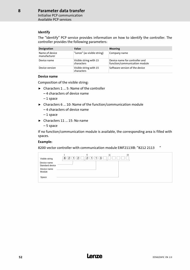
Device name
Composition of the visible string:
ƒ Characters 1 ... 5: Name of the controller
– 4 characters of device name
– 1 space
ƒ Characters 6 ... 10: Name of the function/communication module
– 4 characters of device name
– 1 space
ƒ Characters 11 ... 15: No name
– 5 space
If no function/communication module is available, the corresponding area is filled withspaces.
Example:
8200 vector controller with communication module EMF2113IB: "8212 2113 "
Visible string
Device nameStandard device
Device nameModule
Space
8 2 1 2 2 1 1 3
1 6 11 15

Parameter data transferInitialise PCP communication
Available PCP services
8
� 53EDS82ZAFIC EN 2.0
Device version
Composition of the visible string:
ƒ Characters 1 ... 5: Software version of the controller:
– 2 characters of basic version
– 2 characters of variant
– 1 character of version of variant
ƒ Characters 6 ... 10: Software version of the function/communication module
– 2 characters of basic version
– 2 characters of variant
– 1 character of version of variant
ƒ Characters 11 ... 15: No name
– 5 spaces
Example:
8200 vector controller (version V3.7; without variant and variant version) withcommunication module (version V2.0; without variant and variant version):"3700020000 "
Visible string
Device versionStandard device
Device versionModule
Space
3 7 0 0 2 0 0 00 0
1 6 11 15
Status
The "Status" PCP service provides status information on the controller. The controllerprovides the following values:
Status Value Meaning
Logical status 0 = ready for communication Information on the current operating mode (C0001) ofthe controller regarding communication
Physical status � 0 = ready for operationOperating status "OPERATIONENABLED"
� 1 = partly ready for operationall other device states
Information on the current operating status of thecontroller.(for device states, see � 42)
Local detail "Status word" parameter 24−bit value with:� Bit 0 ... 15: "Status word" profile parameter (index =
0x6041)� Bit 16 ... 23: Value 0

DiagnosticsLED status displays
9
� 54 EDS82ZAFIC EN 2.0
9 Diagnostics
9.1 LED status displays
E82ZAFIxxx, E82ZAFI014B
LED
DescriptionPos. Colour Condition
A Yellow Off No communication with the INTERBUS master.
Blinking Communication to the INTERBUS master via the function module isestablished.
On Internal error in the function module
B Green Off � The function module is not supplied with voltage.� The standard device and/or the external voltage supply is/are
switched off.
Blinking The function module is supplied with voltage but not connected to thestandard device.Causes:� The standard device is switched off.� The standard device is in the initialisation phase.� The standard device is not available.
On The function module is supplied with voltage and is connected to thestandard device.
DiagnosticsTroubleshooting and fault elimination
9
� 55EDS82ZAFIC EN 2.0
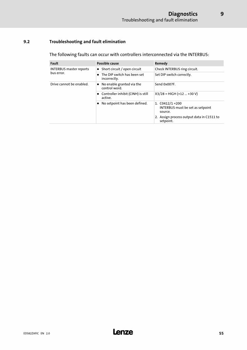
9.2 Troubleshooting and fault elimination
The following faults can occur with controllers interconnected via the INTERBUS:
Fault Possible cause Remedy
INTERBUS master reportsbus error.
� Short circuit / open circuit Check INTERBUS ring circuit.
� The DIP switch has been setincorrectly.
Set DIP switch correctly.
Drive cannot be enabled. � No enable granted via thecontrol word.
Send 0x007F.
� Controller inhibit (CINH) is stillactive.
X3/28 = HIGH (+12 ... +30 V)
� No setpoint has been defined. 1. C0412/1 =200INTERBUS must be set as setpointsource.
2. Assign process output data in C1511 tosetpoint.

Codetabelle10
� 56 EDS82ZAFIC EN 2.0
10 Code table
Overview
Code Subcode Index Designation See
C0002 − 0x5FFD(24573)
Parameter set management � 67
C1500 − 0x5A23(23075)
Software ID � 62
C1501 − 0x5A22(23074)
Software creation date � 62
C1502 1 ... 4 0x5A21(23073)
Display of the software ID � 62
C1503 1 ... 4 0x5A20(23072)
Display of the software creation date � 62
C1510 − 0x5A19(23065)
Configuring process input data � 58
C1511 − 0x5A18(23064)
Configuring process output data � 59
C1512 − 0x5A17(23063)
Enable process output data � 60
C1513 − 0x5A16(23062)
Response monitoring time of the PCDcommunication
� 61
C1514 − 0x5A15(23061)
Monitoring response to PCDcommunication fault
� 61
C1515 − 0x5A14(23060)
Process data specification � 60
C1520 1 ... 10 0x5A0F(23055)
Display of all words to the master � 63
C1521 1 ... 10 0x5A0E(23054)
Display of all words from the master � 63
C1522 1 ... 16 0x5A0D(23053)
Display of all process data words to thestandard device
� 64
C1523 1 ... 16 0x5A0C(23052)
Display of all process data words fromthe standard device
� 65
C1525 − 0x5A0A(23050)
Display of the current setting of the DIPswitches S2 ... S4
� 65
C1530 − 0x5A05(23045)
INTERBUS diagnostics � 66
C1531 1 ... 4 0x5A04(23044)
Bus counter � 66

Codetabelle 10
� 57EDS82ZAFIC EN 2.0
How to read the code table
Column Meaning
Code (Lenze) code
� The parameters of a configurable code marked with an asterisk (<Code>*) can only be accessedvia the communication module.
� The value of a configurable code marked with a double asterisk (<Code>**) is not transmittedwith the parameter set transfer.
Subcode Subcode
Name Designation of the Lenze code
Index Index under which the parameter is addressed.
Lenze Lenze setting of the code
� Display codeConfiguration of this code is not possible.
Values Fixed values determined by Lenze (selection list) or a value range:
Minimum value [Smallest increment/unit] Maximum value
Access R = read access (reading permitted)W = write access (writing permitted)
Data type � FIX32: 32−bit value with sign; decimal with 4 decimal positions� U16: 2 bytes bit−coded� U32: 4 bytes bit−coded� VS: visible string, character string with defined length
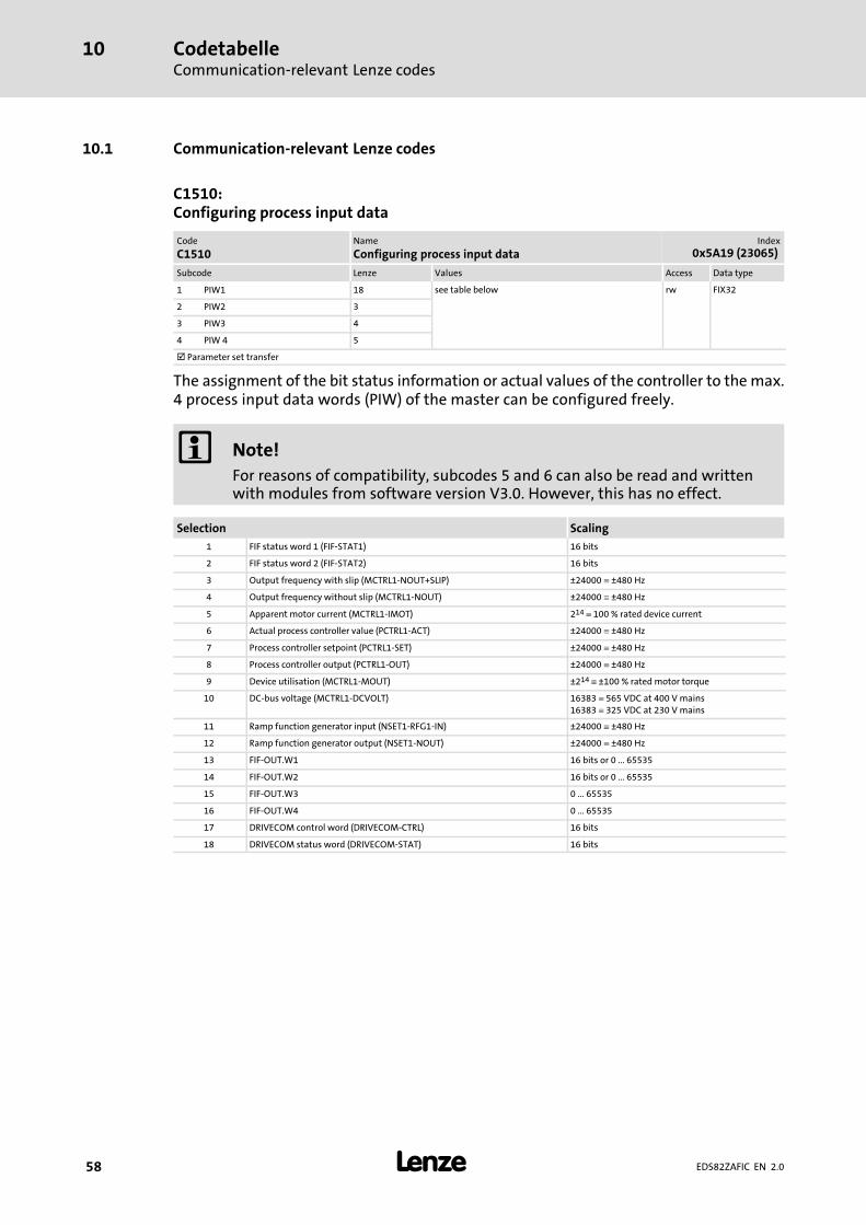
CodetabelleCommunication−relevant Lenze codes
10
� 58 EDS82ZAFIC EN 2.0
10.1 Communication−relevant Lenze codes
C1510:Configuring process input data
Code
C1510Name
Configuring process input dataIndex
0x5A19 (23065)
Subcode Lenze Values Access Data type
1 PIW1 18 see table below rw FIX32
2 PIW2 3
3 PIW3 4
4 PIW 4 5
� Parameter set transfer
The assignment of the bit status information or actual values of the controller to the max.4 process input data words (PIW) of the master can be configured freely.
� Note!
For reasons of compatibility, subcodes 5 and 6 can also be read and writtenwith modules from software version V3.0. However, this has no effect.
Selection Scaling
1 FIF status word 1 (FIF−STAT1) 16 bits
2 FIF status word 2 (FIF−STAT2) 16 bits
3 Output frequency with slip (MCTRL1−NOUT+SLIP) ±24000 � ±480 Hz
4 Output frequency without slip (MCTRL1−NOUT) ±24000 � ±480 Hz
5 Apparent motor current (MCTRL1−IMOT) 214 � 100 % rated device current
6 Actual process controller value (PCTRL1−ACT) ±24000 � ±480 Hz
7 Process controller setpoint (PCTRL1−SET) ±24000 � ±480 Hz
8 Process controller output (PCTRL1−OUT) ±24000 � ±480 Hz
9 Device utilisation (MCTRL1−MOUT) ±214 � ±100 % rated motor torque
10 DC−bus voltage (MCTRL1−DCVOLT) 16383 � 565 VDC at 400 V mains16383 � 325 VDC at 230 V mains
11 Ramp function generator input (NSET1−RFG1−IN) ±24000 � ±480 Hz
12 Ramp function generator output (NSET1−NOUT) ±24000 � ±480 Hz
13 FIF−OUT.W1 16 bits or 0 ... 65535
14 FIF−OUT.W2 16 bits or 0 ... 65535
15 FIF−OUT.W3 0 ... 65535
16 FIF−OUT.W4 0 ... 65535
17 DRIVECOM control word (DRIVECOM−CTRL) 16 bits
18 DRIVECOM status word (DRIVECOM−STAT) 16 bits
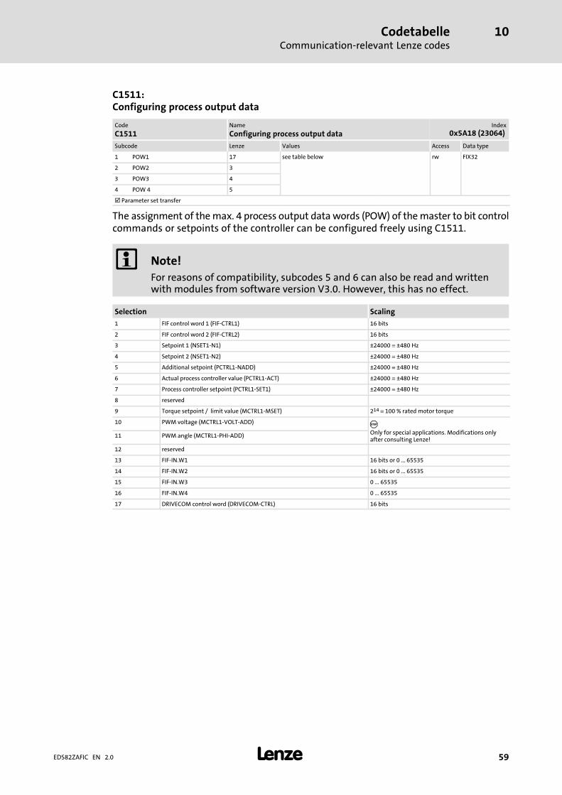
CodetabelleCommunication−relevant Lenze codes
10
� 59EDS82ZAFIC EN 2.0
C1511:Configuring process output data
Code
C1511Name
Configuring process output dataIndex
0x5A18 (23064)
Subcode Lenze Values Access Data type
1 POW1 17 see table below rw FIX32
2 POW2 3
3 POW3 4
4 POW 4 5
� Parameter set transfer
The assignment of the max. 4 process output data words (POW) of the master to bit controlcommands or setpoints of the controller can be configured freely using C1511.
� Note!
For reasons of compatibility, subcodes 5 and 6 can also be read and writtenwith modules from software version V3.0. However, this has no effect.
Selection Scaling
1 FIF control word 1 (FIF−CTRL1) 16 bits
2 FIF control word 2 (FIF−CTRL2) 16 bits
3 Setpoint 1 (NSET1−N1) ±24000 � ±480 Hz
4 Setpoint 2 (NSET1−N2) ±24000 � ±480 Hz
5 Additional setpoint (PCTRL1−NADD) ±24000 � ±480 Hz
6 Actual process controller value (PCTRL1−ACT) ±24000 � ±480 Hz
7 Process controller setpoint (PCTRL1−SET1) ±24000 � ±480 Hz
8 reserved
9 Torque setpoint / limit value (MCTRL1−MSET) 214 � 100 % rated motor torque
10 PWM voltage (MCTRL1−VOLT−ADD) �Only for special applications. Modifications onlyafter consulting Lenze!
11 PWM angle (MCTRL1−PHI−ADD)
12 reserved
13 FIF−IN.W1 16 bits or 0 ... 65535
14 FIF−IN.W2 16 bits or 0 ... 65535
15 FIF−IN.W3 0 ... 65535
16 FIF−IN.W4 0 ... 65535
17 DRIVECOM control word (DRIVECOM−CTRL) 16 bits

CodetabelleCommunication−relevant Lenze codes
10
� 60 EDS82ZAFIC EN 2.0
C1512:Enable process output data
Code
C1512Name
Enable process output dataIndex
0x5A17 (23063)
Subcode Lenze Values Access Data type
− 1 1 [1] 255 rw FIX32
� Parameter set transfer
When C1511 is changed, the process output data is automatically locked to ensure dataconsistency.
C1512 serves to unlock single or all process output data words (POW) again.
The decimal value of the bit settings enables any combination of the process output datawords (POW).
ƒ 0 = Lock output word
ƒ 1 = Unlock output word
Valency of the bit settings
POW 4 POW 3 POW 2 POW 1
23 22 21 20
The value 16 (0x10) in code C1512 serves to enable all process output data.
C1515:Process/parameter data specification
Code
C1515Name
Process/parameter data specificationIndex
0x5A14 (23060)
Subcode Lenze Values Access Data type
− 0 0, 1, 4, 5 rw FIX32
11 ... 14
21 ... 23
� Parameter set transfer
This code serves to change the number of process and parameter data words:
Values Description
0, 1, 4, 5 The configuration resulting from the settings of the DIP switches S2 ... S4 isaccepted according to the valency entered.
11 ... 14 � No PCP� 11 (1 word PCD) ... 14 (4 words PCD)
21 ... 23 � 1 word PCP� 21 (1 word PCD) ... 23 (3 words PCD)
� Note!
ƒ The settings of this code only become active if the DIP switches S2 ... S4 areset to ON ( .
ƒ Switch off the voltage supply of the function/communication module andthen on again to activate changed settings.

CodetabelleMonitoring
10
� 61EDS82ZAFIC EN 2.0
10.2 Monitoring
C1513:Response monitoring time of the PCD communication
Code
C1513Name
Response monitoring time of the PCD communicationIndex
0x5A16 (23062)
Subcode Lenze Values Access Data type
− 65535 0 [1 ms] 65535 rw FIX32
� Parameter set transfer
Monitoring starts with the arrival of the first telegram.
If there is no message from the master within the response monitoring time set, theresponse set in C1514 is carried out.
� Note!
A change of monitoring will be effective immediately.
The value 65535 switches off the response monitoring time.
C1514:Monitoring response to PCD communication fault
Code
C1514Name
Monitoring response to PCD communication faultIndex
0x5A15 (23061)
Subcode Lenze Values Access Data type
− 0 0 No action rw FIX32
1 TRIP (trouble)
2 CINH (controller inhibit)
3 QSP (quick stop)
� Parameter set transfer
If there is no message from the master within the response monitoring time (configurablein C1513), the response set in this code is carried out.
� Note!
A change of the monitoring response will be effective immediately.
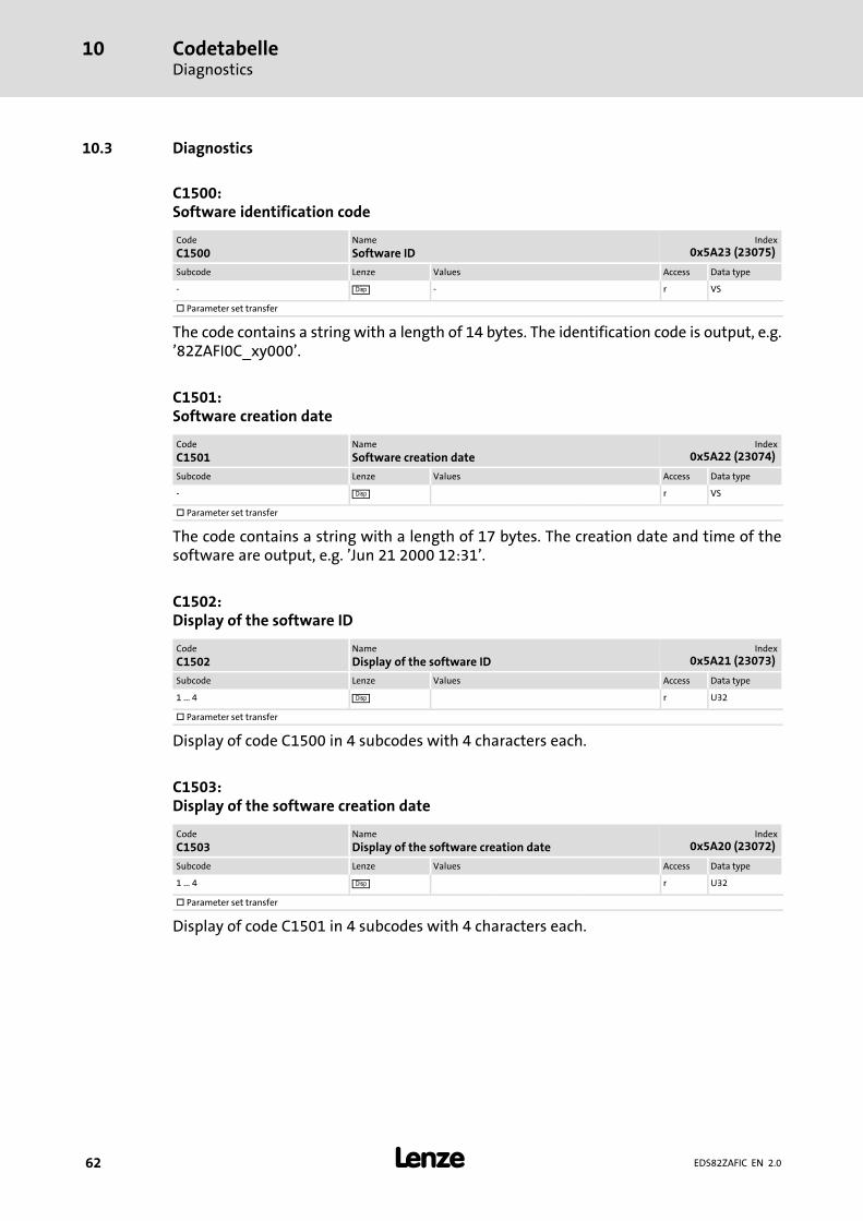
CodetabelleDiagnostics
10
� 62 EDS82ZAFIC EN 2.0
10.3 Diagnostics
C1500:Software identification code
Code
C1500Name
Software IDIndex
0x5A23 (23075)
Subcode Lenze Values Access Data type
− � − r VS
� Parameter set transfer
The code contains a string with a length of 14 bytes. The identification code is output, e.g.’82ZAFI0C_xy000’.
C1501:Software creation date
Code
C1501Name
Software creation dateIndex
0x5A22 (23074)
Subcode Lenze Values Access Data type
− � r VS
� Parameter set transfer
The code contains a string with a length of 17 bytes. The creation date and time of thesoftware are output, e.g. ’Jun 21 2000 12:31’.
C1502:Display of the software ID
Code
C1502Name
Display of the software IDIndex
0x5A21 (23073)
Subcode Lenze Values Access Data type
1 ... 4 � r U32
� Parameter set transfer
Display of code C1500 in 4 subcodes with 4 characters each.
C1503:Display of the software creation date
Code
C1503Name
Display of the software creation dateIndex
0x5A20 (23072)
Subcode Lenze Values Access Data type
1 ... 4 � r U32
� Parameter set transfer
Display of code C1501 in 4 subcodes with 4 characters each.

CodetabelleDiagnostics
10
� 63EDS82ZAFIC EN 2.0
C1520:Display of all words to the master
Code
C1520Name
Display of all words to the masterIndex
0x5A0F (23055)
Subcode Lenze Values Access Data type
1 PIW 1 � 0 [1] 65535 r U16
2 PIW 2
3 PIW 3
4 PIW 4
� Parameter set transfer
Display of the process input data words 1 ... 4 under the single subcodes. All words aredisplayed, but only the configured ones are valid.
C1521:Display of all words from the master
Code
C1521Name
Display of all words from the masterIndex
0x5A0E (23054)
Subcode Lenze Values Access Data type
1 POW1 � 0 [1] 65535 r U16
2 POW2
3 POW3
4 POW4
� Parameter set transfer
Display of the process output data words 1 ... 4 under the single subcodes. All words aredisplayed, but only the configured ones are valid.

CodetabelleDiagnostics
10
� 64 EDS82ZAFIC EN 2.0
C1522:Display of all process data words to the standard device
Code
C1522Name
Display of all process data words to the standard deviceIndex
0x5A0D (23053)
Subcode Lenze Values Access Data type
1 ... 16 � 0 [1] 65535 r U16
� Parameter set transfer
Display of the process data output words 1 ... 16 that are transferred from thefunction/communication module to the standard device:
Subcode Process data word
1 FIF control word 1 (FIF−CTRL1)
2 FIF control word 2 (FIF−CTRL2)
3 Setpoint 1 (NSET1−N1)
4 Setpoint 2 (NSET1−N2)
5 Additional setpoint (PCTRL1−NADD)
6 Actual process controller value (PCTRL1−ACT)
7 Process controller setpoint (PCTRL1−SET1)
8 reserved
9 Torque setpoint or torque limit (MCTRL1−MSET)
10 PWM voltage (MCTRL1−VOLT−ADD)
11 PWM angle (MCTRL1−PHI−ADD)
12 reserved
13 FIF−IN.W1
14 FIF−IN.W2
15 FIF−IN.W3
16 FIF−IN.W4

CodetabelleDiagnostics
10
� 65EDS82ZAFIC EN 2.0
C1523:Display of all process data words from the standard device
Code
C1523Name
Display of all process data words from the standarddevice
Index
0x5A0C (23052)
Subcode Lenze Values Access Data type
1 ... 16 � 0 [1] 65535 r U16
� Parameter set transfer
Display of the process data words 1 ... 16 that are transferred from the standard device tothe function/communication module:
Subcode Process data word
1 FIF status word 1 (FIF−STAT1)
2 FIF status word 2 (FIF−STAT2)
3 Output frequency with slip (MCTRL1−NOUT+SLIP)
4 Output frequency without slip (MCTRL1−NOUT)
5 Apparent motor current (MCTRL1−IMOT)
6 Actual process controller value (PCTRL1−ACT)
7 Process controller setpoint (PCTRL1−SET)
8 Process controller output (PCTRL1−OUT)
9 Device utilisation (MCTRL1−MOUT)
10 DC−bus voltage (MCTRL1−DCVOLT)
11 Ramp function generator input (NSET1−RFG1−IN)
12 Ramp function generator output (NSET1−NOUT)
13 FIF−OUT.W1
14 FIF−OUT.W2
15 FIF−OUT.W3
16 FIF−OUT.W4
C1525:Display of the current DIP switch positions (S2 ... S4)
Code
C1525Name
Display of the current DIP switch positions (S2 ... S4)Index
0x5A0A (23050)
Subcode Lenze Values Access Data type
− � 0 [1] 7 r FIX32
� Parameter set transfer
This code shows the current settings of the DIP switches S2 ... S4. These switches serve toset the number of process and parameter data words ( 30).
DIP switch Value
S2 1
S3 2
S4 4
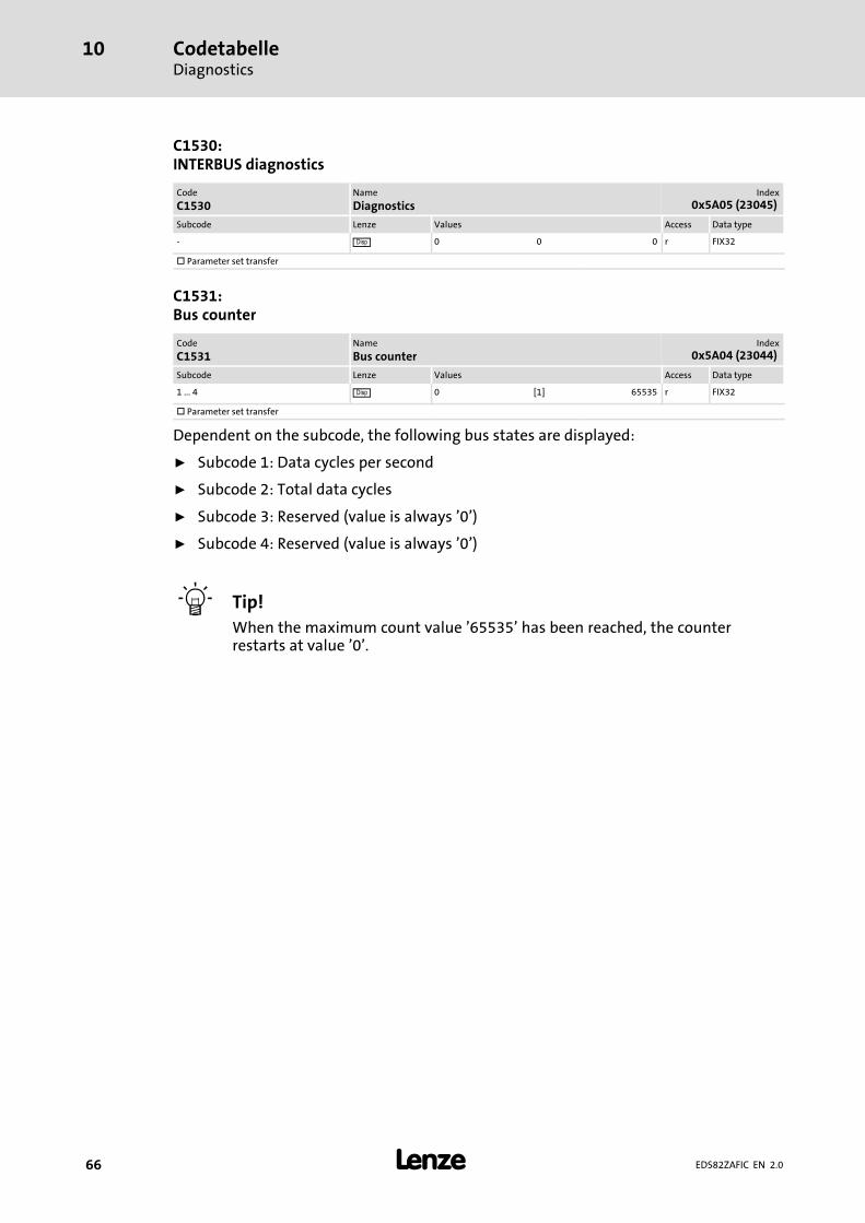
CodetabelleDiagnostics
10
� 66 EDS82ZAFIC EN 2.0
C1530:INTERBUS diagnostics
Code
C1530Name
DiagnosticsIndex
0x5A05 (23045)
Subcode Lenze Values Access Data type
− � 0 0 0 r FIX32
� Parameter set transfer
C1531:Bus counter
Code
C1531Name
Bus counterIndex
0x5A04 (23044)
Subcode Lenze Values Access Data type
1 ... 4 � 0 [1] 65535 r FIX32
� Parameter set transfer
Dependent on the subcode, the following bus states are displayed:
ƒ Subcode 1: Data cycles per second
ƒ Subcode 2: Total data cycles
ƒ Subcode 3: Reserved (value is always ’0’)
ƒ Subcode 4: Reserved (value is always ’0’)
� Tip!
When the maximum count value ’65535’ has been reached, the counterrestarts at value ’0’.

CodetabelleImportant controller codes
10
� 67EDS82ZAFIC EN 2.0
10.4 Important controller codes
C0002:Parameter set management(extract)
Code
C0002Name
Parameter set managementIndex
0x5FFD (24573)
Subcode Lenze Values Access Data type
− 0 0 Ready rw FIX32
1 Lenze setting � PAR1 rw FIX32
2 Lenze setting � PAR2 rw FIX32
3 Lenze setting � PAR3 rw FIX32
4 Lenze setting � PAR4 rw FIX32
31 Lenze setting � FPAR1 rw FIX32
61 Lenze setting � PAR1 + FPAR1 rw FIX32
62 Lenze setting � PAR2 + FPAR1 rw FIX32
63 Lenze setting � PAR3 + FPAR1 rw FIX32
64 Lenze setting � PAR4 + FPAR1 rw FIX32
� Parameter set transfer
In the controller, up to 4 parameter sets (PAR1 ... PAR4) can be saved. In thefunction/communication module, 1 parameter set (FPAR1) can be saved.
By means of parameter setting, the parameter set or sets can be defined in which thedelivery status is to be established.

Index11
�68 EDS82ZAFIC EN 2.0
11 Index
AAbort, 50
Ambient conditions, 14
− Climate, 14
Application as directed, 10
CC0002: Parameter set management , 67
C1500: Software ID, 62
C1501: Software creation date , 62
C1502: Display of the software ID , 62
C1503: Display of the software creation date , 62
C1510: Configuring process input data , 58
C1511: Configuring process output data , 59
C1512: Enable process output data , 60
C1513: Response monitoring time of the PCDcommunication, 61
C1514: Monitoring response to PCD communication fault,61
C1515: Process/parameter data specification, 60
C1520: Display of all words to the master , 63
C1521: Display of all words from the master, 63
C1522: Display of all process data words, 64
C1523: Display of all process data words from thestandard device, 65
C1525: Display of the current DIP switch position (S2...S4),65
C1530: INTERBUS diagnostics, 66
C1531: Bus counter, 66
Cable cross−sections, 24
Cable specification, 20
CE−typical drive system, 19
Code number, access via the fieldbus module, 47
Code number / Index, conversion, 47
Code table, 56
Codes, 58
− Lenze, 47
Commissioning, 26
− defining the user data length, 30
− setting for last bus node, 29
Commissioning steps, 27
Communication medium, 13
Communication Relation List (CRL), 49
Communication time, 13 , 16
Communication−relevant Lenze codes, 58
Configuration, Code table, 56
Connections, 11
Control, DRIVECOM, 42
control word, 35
Controller codes, 67
Conversion formula, Lenze codes, 47
CRL entries, 49
Cycle time, 16
DDefining the user data length, 30
Definition of notes used, 7
Definitions, 6
Device control, Lenze, 34
Device protection, 9 , 18
Diagnostics, 54
DIP switch, S1 − setting for last node, 29
Drive profile, 13
DRIVECOM
− Bit control commands, 45
− Control word, 43
− State machine, 42
− Status bits, 46
− Status word, 44
DRIVECOM control, 42
EElectrical installation, 19
External voltage supply, 21
FFault elimination, 55
Frequency setpoint, 35
GGet−OD, 51

Index 11
� 69EDS82ZAFIC EN 2.0
IID code, 13
Identification, 10 , 52
Identify, 52
Index, conversion, 47
Initiate, 50
Installation, 18
− electrical, 19
− mechanical, 18
− Terminals, Assignment, 23
INTERBUS Cycle time, 16
INTERBUS identification, 13
Interfaces, 11
Internal DC voltage supply, 21
LLED status displays, 54
Lenze codes, 47 , 58
− C0002, 67
− C1500, 62
− C1501, 62
− C1502, 62
− C1503, 62
− C1510, 58
− C1511, 59
− C1512, 60
− C1513, 61
− C1514, 61
− C1515, 60
− C1520, 63
− C1521, 63
− C1522, 64
− C1523, 65
− C1525, 65
− C1530, 66
− C1531, 66
− conversion formula, 47
Lenze data types, 47
MMaster, Settings, 29
Mechanical installation, 18
Monitoring, 61
NNameplate, 10
Nameplate data, 10
Network topology, 13
Notes, definition, 7
PParameter, C0142 (protection against unexpectedstart−up), 32
parameter
− control word (C0135), 35
− frequency setpoint (C0046), 35
Parameter data channel, configure, 47
Parameter data transfer, 47
Parameter data words (PCP), 13
Parameter sets, 8200 vector, 48
PCP communication, initialise, 49
PCP services, 13 , 49
− abort, 50
− get−OD, 51
− identify, 52
− initiate, 50
− read and write, 51
− status, 53
PDU length, 13
Plug connectors, 25
− Use, spring connection, 25
Pollution, 14
Process data signals
− 8200 motec, 36
− 8200 vector, 36
Process data transfer, 33 , 34
process data words (PCD), 13
Process input data, configuring, 39
Processing time, 16
Processing time in the 8200 vector/motec, 16
Product description, 10
− application as directed, 10
PROFIBUS−DP function module, baud rate, 13
Protection against uncontrolled start−up, 32
Protection against unexpected start−up, 32
Protection of persons, 9
Protective insulation, 14

Index11
�70 EDS82ZAFIC EN 2.0
RRead and Write, 51
Residual hazards, 9
SSafety instructions, 8
− application as directed, 10
− definition, 7
− device− and application−specific, 9
− layout, 7
Screw−tightening torques, 24
Services, PCP, 49
Settings
− DIP switch, S1 − setting for last node, 29
− Master, 29
Specification of the transmission cable, 20
Status, 53
Status displays, 54
TTechnical data, 13
Terminals, Assignment, 23
Transmission cable, specification, 20
Troubleshooting, 55
Troubleshooting and fault elimination, Monitoring, 61
Type code, 10
− finding, 10
UUsage conditions, Ambient conditions, Climate, 14
Use of plug connectors, 25
VValidity of the documentation, 4
Value range, 47
Voltage supply, 21
− internal, 21
Voltage supply: external, 21
WWiring according to EMC, 19
Wiring with a host (master), 20

�© 02/2012
� Lenze Drives GmbHPostfach 10 13 52D−31763 HamelnGermany
Service Lenze Service GmbHBreslauer Straße 3D−32699 ExtertalGermany
+49�(0)51�54�/ 82−0 00�80�00�/ 24�4�68�77 (24 h helpline)
� +49�(0)51�54�/ 82−28 00 � +49�(0)51�54�/ 82−11 12
� [email protected] � [email protected]
� www.Lenze.com
EDS82ZAFIC .IDp EN 2.0 TD17
10 9 8 7 6 5 4 3 2 1