communications error processing (y02 for port 1 and...
TRANSCRIPT

5-200
Communications error processing (y02 for port 1 and y12 for port 2) y02 or y12 specifies the error processing to be performed if an RS-485 communications error occurs. RS-485 communications errors include logical errors (such as address error, parity error, framing error), transmission protocol error, and physical errors (such as no-response error specified by y08 and y18). The inverter can recognize such an error only when it is configured with a run or frequency command sourced through the RS-485 communications link and it is running. If none of run and frequency commands is sourced through the RS-485 communications link or the inverter is not running, the inverter does not recognize any error occurrence.
Data for y02, y12 Function
0 Immediately trip, displaying an RS-485 communications error (er8 for y02 and erp for y12). (The inverter stops with alarm issue.)
1 Run during the period specified by the error processing timer (y03, y13), display an RS-485 communications error (er8 for y02 and erp for y12), and then stop operation. (The inverter stops with alarm issue.)
2
Retry communication during the period specified by the error processing timer (y03, y13). If a communications link is recovered, continue operation. Otherwise, display an RS-485 communications error (er8 for y02 and erp for y12) and stop operation. (The inverter stops with alarm issue.)
3 Continue to run even when a communications error occurs.
For details, refer to the RS-485 Communication User's Manual (MEH448).
Timer (y03 for port 1 and y13 for port 2) y03 or y13 specifies an error processing timer. If the timer count has elapsed due to no response from the other end when a query has been issued, the inverter interprets it as an error occurrence. See the "No-response error detection time (y08, y18)" given on the next page. - Data setting range: 0.0 to 60.0 (s)
Baud rate (y04 for port 1 and y14 for port 2)
Data for y04 and y14 Transmission speed (bps)
0 2400
1 4800
2 9600
3 19200
y04 or y14 specifies the transmission speed for RS-485 communication. For FRENIC Loader (via the RS-485 communications link), specify the transmission speed that matches the connected computer.
4 38400
Data length (y05 for port 1 and y15 for port 2)
Data for y05 and y15 Data length
0 8 bits
1 7 bits
y05 or y15 specifies the character length for RS-485 communication. For FRENIC Loader (via the RS-485 communications link), no setting is required since Loader automatically sets 8 bits. (The same applies to the Modbus RTU protocol.)
5.4 Details of Function Codes
5-201
Chap. 5
FUN
CTIO
N C
OD
ES
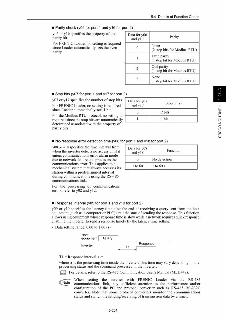
Parity check (y06 for port 1 and y16 for port 2)
Data for y06 and y16 Parity
0 None (2 stop bits for Modbus RTU)
1 Even parity (1 stop bit for Modbus RTU)
2 Odd parity (1 stop bit for Modbus RTU)
y06 or y16 specifies the property of the parity bit. For FRENIC Loader, no setting is required since Loader automatically sets the even parity.
3 None (1 stop bit for Modbus RTU)
Stop bits (y07 for port 1 and y17 for port 2)
Data for y07 and y17 Stop bit(s)
0 2 bits
1 1 bit
y07 or y17 specifies the number of stop bits.For FRENIC Loader, no setting is required since Loader automatically sets 1 bit. For the Modbus RTU protocol, no setting is required since the stop bits are automatically determined associated with the property of parity bits.
No-response error detection time (y08 for port 1 and y18 for port 2)
Data for y08 and y18 Function
0 No detection
1 to 60 1 to 60 s
y08 or y18 specifies the time interval from when the inverter detects no access until it enters communications error alarm mode due to network failure and processes the communications error. This applies to a mechanical system that always accesses its station within a predetermined interval during communications using the RS-485 communications link. For the processing of communications errors, refer to y02 and y12.
Response interval (y09 for port 1 and y19 for port 2) y09 or y19 specifies the latency time after the end of receiving a query sent from the host equipment (such as a computer or PLC) until the start of sending the response. This function allows using equipment whose response time is slow while a network requires quick response, enabling the inverter to send a response timely by the latency time setting. - Data setting range: 0.00 to 1.00 (s)
T1 = Response interval + α where α is the processing time inside the inverter. This time may vary depending on the processing status and the command processed in the inverter.
For details, refer to the RS-485 Communication User's Manual (MEH448).
When setting the inverter with FRENIC Loader via the RS-485 communications link, pay sufficient attention to the performance and/or configuration of the PC and protocol converter such as RS-485−RS-232Cconverter. Note that some protocol converters monitor the communications status and switch the sending/receiving of transmission data by a timer.

5-202
Protocol selection (y10 for port 1)
Data for y10 Protocol
0 Modbus RTU protocol
1 FRENIC Loader protocol
y10 specifies the communications protocol for port 1. For FRENIC Loader (via the RS-485 communications link), only y10 can be used for protocol selection. Set the y10 data at "1." 2 Fuji general-purpose
inverter protocol
Protocol selection (y20 for port 2)
Data for y20 Protocol
0 Modbus RTU protocol
y20 specifies the communications protocol for port 2.
2 Fuji general-purpose inverter protocol
y97 Communication Data Storage Selection A nonvolatile storage in the inverter has a limited number of rewritable times (100,000 to 1,000,000 times). Saving data into the storage so many times unnecessarily will no longer allow the storage to save data, causing memory errors. For frequent data writing via the communications link, therefore, a temporary storage is provided instead of the nonvolatile storage. To use the temporary storage, set the y97 data at "1." Using the temporary storage reduces the number of data writing times into the nonvolatile storage, preventing memory errors. Setting the y97 data at "2" saves all data written in the temporary storage into the nonvolatile one. Changing the y97 data requires simultaneous keying of and / keys.
Data for y97 Function
0 Save into nonvolatile storage (Rewritable times limited)
1 Write into temporary storage (Rewritable times unlimited)
2 Save all data from temporary storage to nonvolatile one (After saving data, the data automatically returns to "1.")
y98 Bus Link Function (Mode selection) (Refer to H30.)
Refer to the description of H30.
5.4 Details of Function Codes
5-203
Chap. 5
FUN
CTIO
N C
OD
ES
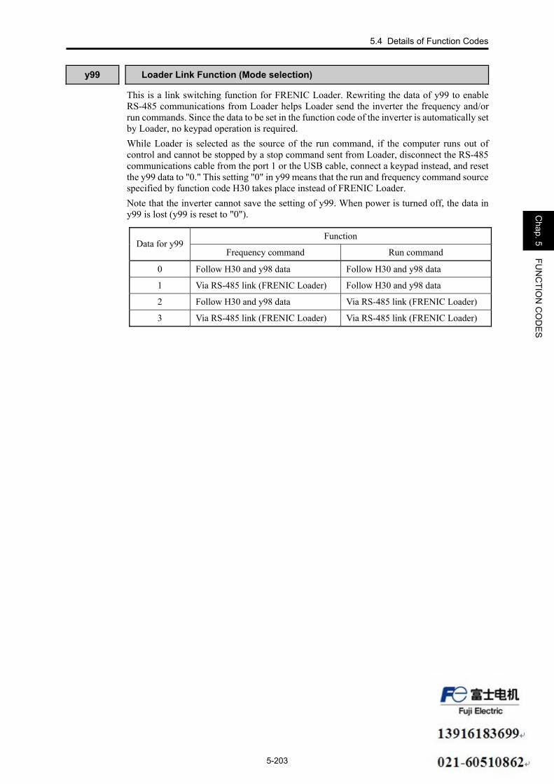
y99 Loader Link Function (Mode selection)
This is a link switching function for FRENIC Loader. Rewriting the data of y99 to enable RS-485 communications from Loader helps Loader send the inverter the frequency and/or run commands. Since the data to be set in the function code of the inverter is automatically set by Loader, no keypad operation is required. While Loader is selected as the source of the run command, if the computer runs out of control and cannot be stopped by a stop command sent from Loader, disconnect the RS-485 communications cable from the port 1 or the USB cable, connect a keypad instead, and reset the y99 data to "0." This setting "0" in y99 means that the run and frequency command source specified by function code H30 takes place instead of FRENIC Loader. Note that the inverter cannot save the setting of y99. When power is turned off, the data in y99 is lost (y99 is reset to "0").
Function Data for y99
Frequency command Run command
0 Follow H30 and y98 data Follow H30 and y98 data
1 Via RS-485 link (FRENIC Loader) Follow H30 and y98 data
2 Follow H30 and y98 data Via RS-485 link (FRENIC Loader)
3 Via RS-485 link (FRENIC Loader) Via RS-485 link (FRENIC Loader)


Chapter 6
BLOCK DIAGRAMS FOR CONTROL LOGIC This chapter provides the main block diagrams for the control logic of the FRENIC-MEGA series of inverters.
Contents 6.1 Symbols Used in Block Diagrams and their Meanings............................................................................... 6-1 6.2 Drive Frequency Command Block.............................................................................................................. 6-2 6.3 Drive Command Block ............................................................................................................................... 6-4 6.4 Control Block.............................................................................................................................................. 6-6
6.4.1 V/f control ........................................................................................................................................... 6-6 6.4.2 Vector control with speed sensor......................................................................................................... 6-8
6.5 PID Process Control Block ....................................................................................................................... 6-10 6.6 PID Dancer Control Block........................................................................................................................ 6-12 6.7 FMA/FMP Output Selector....................................................................................................................... 6-14

6.1 Symbols Used in the Block Diagrams and their Meanings
6-1
Chap. 6
BLO
CK
DIA
GR
AM
S FO
R C
ON
TRO
L LOG
IC
FRENIC-MEGA series of inverters is equipped with a number of function codes to match a variety of motor operations required in your system. Refer to Chapter 5 "FUNCTION CODES" for details of the function codes. The function codes have functional relationship each other. Several special function codes also work with execution priority each other depending on their functions or data settings. This chapter explains the main block diagrams for control logic in the inverter. You are requested to fully understand the inverter's control logic together with the function codes in order to set the function code data correctly. The block diagrams contained in this chapter show only function codes having mutual relationship. For the function codes that work independently and for detailed explanation of each function code, refer to Chapter 5 "FUNCTION CODES."
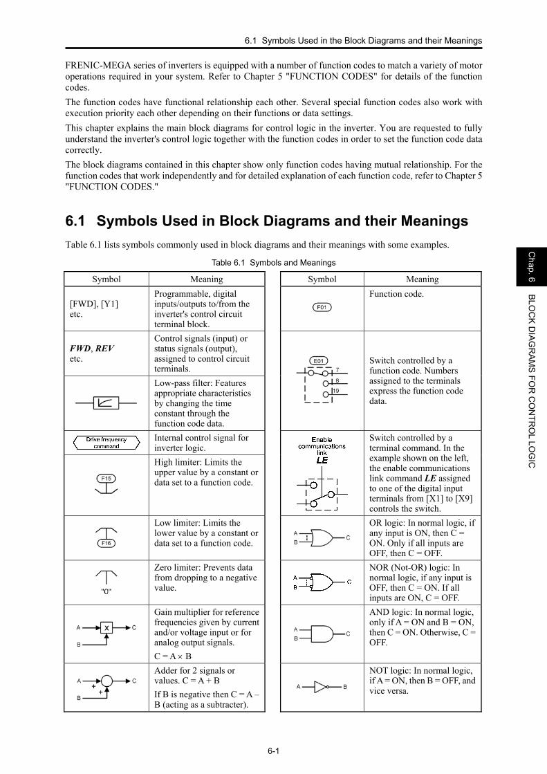
6.1 Symbols Used in Block Diagrams and their Meanings Table 6.1 lists symbols commonly used in block diagrams and their meanings with some examples.
Table 6.1 Symbols and Meanings
Symbol Meaning Symbol Meaning
[FWD], [Y1] etc.
Programmable, digital inputs/outputs to/from the inverter's control circuit terminal block.
Function code.
FWD, REV etc.
Control signals (input) or status signals (output), assigned to control circuit terminals.
Low-pass filter: Features appropriate characteristics by changing the time constant through the function code data.
Switch controlled by a function code. Numbers assigned to the terminals express the function code data.
Internal control signal for inverter logic.
High limiter: Limits the upper value by a constant or data set to a function code.
Switch controlled by a terminal command. In the example shown on the left, the enable communications link command LE assigned to one of the digital input terminals from [X1] to [X9] controls the switch.
Low limiter: Limits the lower value by a constant or data set to a function code.
OR logic: In normal logic, if any input is ON, then C = ON. Only if all inputs are OFF, then C = OFF.
Zero limiter: Prevents data from dropping to a negative value.
NOR (Not-OR) logic: In normal logic, if any input is OFF, then C = ON. If all inputs are ON, C = OFF.
Gain multiplier for reference frequencies given by current and/or voltage input or for analog output signals. C = A × B
AND logic: In normal logic, only if A = ON and B = ON, then C = ON. Otherwise, C = OFF.
Adder for 2 signals or values. C = A + B If B is negative then C = A – B (acting as a subtracter).
NOT logic: In normal logic, if A = ON, then B = OFF, and vice versa.

6-2
6.2 Drive Frequency Command Block
[V2]
++
Gain
Gain
Gain Bias
++
C39C37
C34C32
C37 C39 F18 C50
×
×
×
×
C53
Selection of normal/inverseoperation
Normal/inverseoperation
Normal/inverseoperation
Normal/inverseoperation
Normal/inverseoperation
Normal/inverseoperation
Gain BiasC42 C44 F18 C50
GainC44C42
×
UP/DOWNcontrol
UPcommand
UPDOWN
commandDOWN
H61
[12]
[C1]
[C1] filter
Key operation on the keypadLED monitor
Load shaft speedcommand
3
4
5
Balanceless-bumpless(F01,C30 = 8)
Motor speed in r/min
Line speed command
0,1,2
Thermistor(Level)
E48
A
C
DC43
C38
7Display speed in %
HardwareswitchSW5 H26=0
H26=1,2
=PTC/NTC
C31
+
++C36
[C1] Offset
Alarm0h4
Compa-rator
Referencelossdetection
E65 ≠999
E65
E65
B+
[12] Offset
Continue-to-runfrequency at[12]E65
PolarityC35=1
C33[12] Filter
UP/DOWN controlInitial frequency setting
H27
Thermistor(Mode selection)
Reference loss detection
Reference loss detection
Reference loss detection
Continue-to-runfrequency at[C1]
Continue-to-runfrequency at[V2]
≠0
0
Frequencycommand viacommunications
S01
S05Host equipment
OFF if y98=1,3orH30=1,3,7
Host equipment
Host equipment
OFF if y98=1,3orH30=4,5,8
OFF ifH30=1,3 to 5,7,8
RS-485 COM port 1RJ-45 connector toconnect with keypad
E
Lastcommandto take effect
S01
*2Fieldbus card(option)
++
Gain BiasC32 C34 F18 C50
Normal/inverseoperation×
PolarityC35=1
Switchnormal/inverseoperationIVS
1
2
3
4
5
6
7
8
H26=3
1
2 Motor overheatdetected bythermistor (PTC)THM
Motor temperaturedetected by thermistor(NTC)
Frequency/speedcommandconverter
Host equipmentFrequency/speed
commandconverter
Pulse train inputPIN
Pulse train signSIGN
d62
d63
d59d62d63
Pulse count factor 1
Pulse count factor 2
Pulse count factor 1Pulse count factor 2
Pulse input property
d61 Command (pulse rate input)Filter time constant
PolarityC45=1
Thermistor(Mode selection)
H26
++C41
[V2] Offset
Reference frequency
Thermistor(Mode selection)
*2
Thermistor(Mode selection)
ON
OFF
With option
=V2
×
"-1"
RS-485 COM port 2Control circuit terminalsDX+ and DX-
[V2] filter
0 limiter"0" 0 limiter
"0"
0 limiter"0"
0 limiter"0"
PG interfacecard (option)
Figure 6.1 (1) Drive Frequency Command Block

6.2 Drive Frequency Command Block
6-3
Chap. 6
BLO
CK
DIA
GR
AM
S FO
R C
ON
TRO
L LOG
IC
Jumpfrequency
Select frequencycommand 2/1Hz2/Hz1
Enablecommunicationslink via RS-485or fieldbusLE
Selectmulti-frequencySS1,SS2,SS4,SS8
+
+
+
+
Auxiliary frequencyreference 1
Auxiliary frequency reference 2
Frequencylimiter(Low)
Frequencylimiter (High)
Drive frequencycommand
01
2
3
5*3
[C1]
[12]
+
+
0,8
1
2
3
5
+
0,8
1
2
3
Frequencycommand 2
Frequencycommand 1
5
+
F01
C30
C01C02C03C04C05
C06
C07
C08
C09
C10
C11
GainC34C32
GainC39C37
E62
F16
F15
×
×
×
×
7
7
*3
*1
GainC44C42
E63
×
×
Communicationslink function
0,2,6
1,3 to 5,7,8 0,2
1,3
H30
y99
Bus link functiony98
0,2
1,3
Loader link function
*1
*1
[V2]
E61
H63
Low limiter(Modeselection)
B
C
D
E
C19
C20
+Ready for
joggingJOG
Joggingfrequency
12
12
C12
C13
C14
C15
C16
C17
C18
7
8
1
2
3
4
5
6
×
×
×
×
×
×
×
×
×
×
×
×
×
×
×
×
×
×
×
×
×
×
×
×
×
Ratio setting
6
78
01
2
3
56
7
8
*3
01
2
3
56
78 Analog torque limit value B
Analog torque limit value B
20
20
20
LED display
Displaycoefficient
E41E40
×
Analog torque limit value A
Analog torque limit value A
Analog torque limit value B
Ratio setting
Multi-frequency 1
Multi-frequency 2
Multi-frequency 3
Multi-frequency 4
Multi-frequency 5
Multi-frequency 6
Multi-frequency 7
Multi-frequency 8
Multi-frequency 9
Multi-frequency 10
Multi-frequency 11
Multi-frequency 12
Multi-frequency 13
Multi-frequency 14
Multi-frequency 15
Ratio setting
8888
Multi-functionkeypad
Select local(keypad)operationLOC
A
A
Remote/local decision
Analog torque limit value A
*1 Takes priority when the same function has been assigned by E61, E62 and E63: Terminal [12] > Terminal [C1] > Terminal [V2]*2 For details of the options, refer to the instruction manual for each option.*3 Refer to block diagrams of PID control block for details.
Notes:- When PID control is enabled, the control logic differs from this block diagram.- S codes are communication-related function codes. Refer to the RS-485 Communication User's Manual for details.
Figure 6.1 (2) Drive Frequency Command Block

6-4
6.3 Drive Command Block
0 1 2
Ope
ratio
nm
etho
d
3
F02
Hol
d
Mul
ti-fu
nctio
nke
ypad
Sta
ndar
d ke
ypad
Hol
d in
rota
ting
dire
ctio
n
Hol
d
Ena
ble
3-w
ireop
erat
ion
HLD
Run
forw
ard FW
DR
un re
vers
e REV
Com
mun
icat
ions
link
func
tion
0,1,
4
2,3,
5 to
8
Load
er li
nkfu
nctio
n
0,1
2,3
Ena
ble
com
mun
icat
ions
link
via
RS
-485
or f
ield
bus
LE
H30
y99
Bus
link
func
tion
y98
0,1
2,3
FWD
/REV
FWD
only
REV
only
Hos
t equ
ipm
ent
OFF
if y
98=2
,3or H
30=2
,3,5
Hos
t equ
ipm
ent
Hos
t equ
ipm
ent
OFF
if y
98=2
,3or H
30=6
to 8
OFF
ifH
30=2
,3,5
to 8
FWD
RE
V
[X1]
[X2]
[X6]
[X3]
[X4]
[X5]
Bit
10
Bit
11
Bit
12
Bit
13B
it 14
Bit
15
XF
[FW
D]
[X7]
[X8]
[X9]
Fixe
d at
0Fi
xed
at 0
XR
[RE
V]R
ST
ON
if E
98=9
8
ON
if E
98=9
9
ON
if E
99=9
8
ON
if E
99=9
9
FWD
Pro
cess
or
REV
Pro
cess
or
FWD
REV
FWD
REV
FWD
RE
V
ON
if H
96=1
,3
Driv
e fre
quen
cyco
mm
and
Sta
rting
freq
uenc
y 1
Sto
p fre
quen
cyF2
3
F25
S06
Run
com
man
d
Run
deci
sion
REV
FWD
Forc
ed to
OFF
ifFW
D =
ON
and
REV
= O
N
Bit
0
Bit
1
Bit
2B
it 3
Bit
4
Bit
5B
it 6
Bit
7B
it 8
Bit
9
Trut
h ta
ble
for S
06 (b
it 13
, bit
14) p
roce
ssor
s
-:N
ot a
ssig
ned
(Out
puts
the
valu
e of
the
assi
gned
bit.
)
bit 1
3bi
t 14
Out
put
ON
ON
ON
ON
OFF
OFF
OFF
ON
OFF
OFF
OFF
OFF
ON
-O
N
OFF
-O
FF
-O
NO
N
-O
FFO
FF
*1
Forc
e to
sto
pSTOP
Not
e:S
cod
es a
re c
omm
unic
atio
n-re
late
d fu
nctio
n co
des.
Ref
er to
the
RS
-485
Com
mun
icat
ion
Use
r's M
anua
lfo
r det
ails
.La
stco
mm
and
to ta
keef
fect
Rea
dy fo
r jog
ging
oper
atio
n(H
old
disa
bled
)
F16
H63 E65
Freq
uenc
y lim
iter (
Low
)
Low
lim
iter
Ref
eren
ce lo
ss d
etec
tion
Fiel
dbus
car
d(o
ptio
n)*2
*2
For d
etai
ls o
f the
opt
ions
, ref
er to
the
inst
ruct
ion
man
ual
for e
ach
optio
n.
ON
if H
72=1
Mai
n po
wer
loss
det
ectio
n
Det
ecte
d sp
eed
Mul
ti-fu
nctio
nke
ypad
Sel
ect l
ocal
(key
pad)
oper
atio
nLOC
F38
Sto
p fre
quen
cy (D
etec
tion
mod
e)
Rem
ote/
loca
l dec
isio
n
RS
-485
CO
M p
ort 1
RJ-
45 c
onne
ctor
toco
nnec
t with
key
pad
RS
-485
CO
M p
ort 2
Con
trol c
ircui
t ter
min
als
DX
+ an
d D
X-
*1 *1
Figure 6.2 Drive Command Block

6.3 Drive Command Block
6-5
Chap. 6
BLO
CK
DIA
GR
AM
S FO
R C
ON
TRO
L LOG
IC
This page is intentionally left blank.
6-6
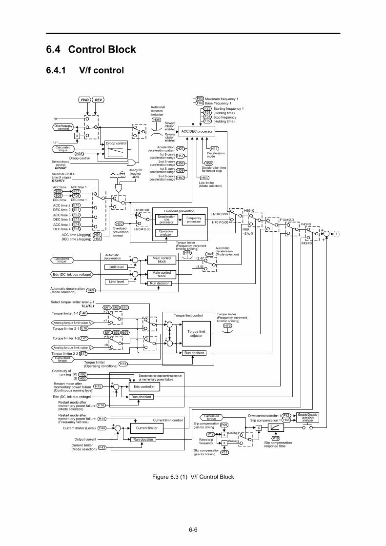
6.4 Control Block
6.4.1 V/f control
Drive frequencycommand
"-1"
"0"
ACC/DEC processor
F03F04
F23
F25
H70Overloadpreventioncontrol
Overload prevention
Current limiter
Current limit control
F44Current limiter (Level)
Output current
F43Current limiter(Mode selection)
Maximum frequency 1Base frequency 1
Starting frequency 1
+
-
ACC time 1ACC time
DEC time
F07F08
S08S09
DEC time 1
H70≠0.00
H11Decelerationmode
H70=0.00
Torque limitadjuster
F41
+-
H69=2 to 5
H70≠0.00
H70=0,999
F43≠0
F43=0
H69=0
Torque limiter 1-2
E16
Torque limiter 1-1
Torque limiter 2-1
F40
H56Deceleration timefor forced stop
H63Low limiter(Mode selection)
FWD REV
E17Torque limiter 2-2
+-
H76
Torque limiter(Frequency incrementlimit for braking)
Droop control
H08
Rotationaldirectionlimitation
Forwardrotationinhibited
H28Droop control
F24
F39
Calculatedtorque
P09
P12P10
F42H68
Drive control selection 1Slip compensation 1
Slip compensationgain for driving
Rated slipfrequency Slip compensation
response time
X
(Braking)
E10E11
ACC time 2DEC time 2
H14
Select ACC/DECtime (4 steps)RT2/RT1
Select torque limiter level 2/1TL2/TL1
(Holding time)Stop frequency(Holding time)
1
Calculatedtorque
+
+
Select droopcontrolDROOP
H07
H57
H58
H59
H60
1st S-curveacceleration range
E12E13E14E15
Analog torque limit value A
E61 E62 E63
E61 E62 E63
=8
≠7
=7
≠8
H73Torque limiter(Operating conditions)
F14≠2,3
H54H55
ACC time (Jogging)DEC time (Jogging)
Ready forjoggingJOG
X
X
+
(Driving)
P11Slip compensationgain for braking
Run decision
Torque limit control
Run decisionAnalog torque limit value B
Calculatedtorque
Main controlblock
Run decision
H69Automatic deceleration(Mode selection)
+-
H76
Calculatedtorque
Limit level+-
Limit level
Edc (DC link bus voltage)
H69=2,4
=3,5
Automaticdeceleration(Mode selection)Automatic
deceleration
Main controlblock
Torque limiter(Frequency incrementlimit for braking)
Run decision
Decelerate-to-stop/continue to runat momentary power failure
H15Restart mode aftermomentary power failure(Continuous running level)
Edc (DC link bus voltage)
F14
+
-
H92H93
Restart mode aftermomentary power failure(Mode selection)
Edc controller
X
ACC time 3DEC time 3ACC time 4DEC time 4
Continuity ofrunning
(I)(P)
Restart mode aftermomentary power failure(Frequency fall rate)
Reverserotationinhibited
Acceleration/deceleration pattern
2nd S-curveacceleration range
1st S-curvedeceleration range
2nd S-curvedeceleration range
Decelerationrate
processorFrequencyprocessor
Operationanalyzer
Enable/Disableoperationanalyzer
Figure 6.3 (1) V/f Control Block

6.4 Control Block
6-7
Chap. 6
BLO
CK
DIA
GR
AM
S FO
R C
ON
TRO
L LOG
IC
H64 F16H64=0.0
Low limiter(Lower limitingfrequency)
Frequencylimiter(Low)
F15
Voltage calculator
F03F04F05
F09F37
H50H51
P01P23
P53
+-
xH80Output current fluctuationdamping gainfor motor 1
Currentfluctuationsuppressor
Voltagecalculation
Rundecision
DC braking
F21
F20F22(Braking time)
Motor parameters
Frequencylimiter(High)
Torque boost 1Load selection/Auto torque boost/Auto energy saving operation 1Drive control selection 1
EdcCompen-sation
PWMprocessor
Carrierfrequency
F26F27
Carrier frequencyreductionprocessor
Hardwarecurrentlimiter
Motor sound(Carrier frequency)
Edc(DC link busvoltage)
Cancel if H98 = 0
Maximum frequency 1Base frequency 1Rated voltage at base frequency 1Maximum output voltage 1
2-phase/3-phaseconverter
Gate drive circuit
Current limitprocessing
Current limit level
H12
Alarm to0c1 0c3
Cooling fanON/OFFcontrol
H06
M
Instantaneous overcurrentlimiting (Mode selection)
Cooling fanON/OFFcontrolOutput currents
(Iu, Iv, Iw)
Output current(Iu, Iv, Iw)
DC link buscapacitor
MotorCooling fan
1
0
H98
Comparator
(Tone)
H64≠0.0 P99 Motor 1 selection
H71 Decelerationcharacteristics
H95
PWM signals
DC braking
F06
H52H53
(bit 0)
DCBRK
F14H13H14
H09H49
H16
STMAuto search for
idling motor speed
Restart modeafter momentary
power failure
Starting mode (Auto search)(Auto search delay time 1)(Auto search delay time 2)
Restart mode after momentary power failure (Mode selection)(Restart time)
(Frequency fall rate)(Allowable momentary power failure time)
1
Powersupply
Rectifier
H65H66
H67 Auto energy saving operation (Mode selection)
P03toP06
P56
H46
F42
Non-linear V/f pattern 1 (Frequency)
Phaseangle
calculation
Main powerdown detectionH72
Main powerdown detection(Mode selection)
PWMsignals
(Voltage)Non-linear V/f pattern 2 (Frequency)
(Voltage)Non-linear V/f pattern 3 (Frequency)
(Voltage)
toto
(Braking responsemode)
(Braking level)
(Braking startingfrequency)
DC braking 1
Figure 6.3 (2) V/f Control Block

6-8
6.4.2 Vector control with speed sensor
Drive
freq
uenc
yco
mm
and
"-1""0"
F03
F04
F23
F25
H70
Ove
rload
pre
vent
ion
cont
rol
Dec
eler
atio
nra
tepr
oces
sor
Ope
ratio
nan
alyz
er
Freq
uenc
ypr
oces
sor
Can
cel i
f H70
=999
Ove
rload
pre
vent
ion
Max
imum
freq
uenc
y 1
Bas
e fre
quen
cy 1
Sta
rting
freq
uenc
y 1
AC
C ti
me
1AC
C ti
me
DE
C ti
me
F07
F08
S08
S09
DE
C ti
me
1
H70
≠0.
00
H70
=0.0
0
H69
=3,5
H70
≠0.
00
H70
=0,9
99
H69
Aut
omat
ic d
ecel
erat
ion
(Mod
e se
lect
ion)
H69
≠3,
5
FWD
REV
H08
Rot
atio
nal
dire
ctio
nlim
itatio
nFo
rwar
dro
tatio
nin
hibi
ted
F24
F39
E10
E11
AC
C ti
me
2D
EC
tim
e 2
Sel
ect A
CC
/DE
Ctim
e (4
ste
ps)
RT2/RT1
(Hol
ding
tim
e)St
op fr
eque
ncy
(Hol
ding
tim
e)
Reve
rse
rota
tion
inhi
bite
d
E12 E1
3A
CC
tim
e 3
DE
C ti
me
3
E14
E15
AC
C ti
me
4D
EC
tim
e 4
Aut
omat
ic d
ecel
erat
ion
mai
n co
ntro
l blo
ck+ -
Lim
it le
vel
H64
F16H
64=0
.0
Low
lim
iter
(Low
er li
miti
ngfre
quen
cy)
Freq
uenc
ylim
iter
(Low
)
F15
Freq
uenc
ylim
iter
(Hig
h)
H64
≠0.
0
AC
C/D
EC
pro
cess
or
H54
H55
AC
C ti
me
(Jog
ging
)D
EC
tim
e (J
oggi
ng)
Rea
dy fo
rjo
ggin
gJOG
+
X
H11
Dec
eler
atio
n m
ode
H56
Dec
eler
atio
n tim
e fo
rfo
rced
sto
p
H63
Low
lim
iter (
Mod
e se
lect
ion)
H07
H57
H58
H59
H60
A
Mot
or/p
aram
eter
sw
itchi
ng 2
A42
Mot
or/p
aram
eter
sw
itchi
ng 3
b42
Mot
or/p
aram
eter
sw
itchi
ng 4
r42
M2
M3
M4M
otor
2 to
4 s
elec
tion
F40
E16
S10
E61
E63
E61
E63
to
≠7
=7
≠8
=8
Torq
ue li
mite
r via
com
mun
icat
ions
link
F41
E17
S11
Sele
ct to
rque
limite
r lev
el 2
/1TL2/TL1
+300
% (D
rivin
g)
-300
% (B
raki
ng)
to
Torq
ue li
mite
r 1-1
Torq
ue li
mite
r 2-1
Torq
ue li
mite
r 1-2
Torq
ue li
mite
r 2-2
d01
A43
b43
r43
d02
A44 b44
r44
Spe
ed c
omm
and
filte
r
Spe
ed d
etec
tion
filte
r
d09
d10
-+
Sho
ckle
ssop
erat
ion
d03
A45
b45
r46
d12
d04
A46
b46
r45
d11
} } } } }
A A
d25
A
Spee
d co
mm
and
Spe
ed c
ontro
l (jo
ggin
g)(S
peed
com
man
d fil
ter)
Spe
ed c
ontro
l 1 to
4(S
peed
com
man
d fil
ter)
Rea
dy fo
rjo
ggin
gJOG
+
ASR
switc
hing
tim
e
Spe
ed c
ontro
l 1 to
4(S
peed
det
ectio
n fil
ter)
Spe
ed c
ontro
l (jo
ggin
g)(S
peed
det
ectio
n fil
ter)
Spe
ed c
ontro
l 1 to
4P
(Gai
n)I (
Inte
gral
tim
e)
Spe
ed c
ontro
l (jo
ggin
g)P
(Gai
n)I (
Inte
gral
tim
e)
Det
ecte
dsp
eed
Torq
ueco
mm
and
Spe
edco
ntro
ller
Ana
log
torq
ue li
mit
valu
e B
Run
dec
isio
n
DC
link
bus
vol
tage
(Edc
)
Acc
eler
atio
n/de
cele
ratio
n pa
ttern
1st S
-cur
veac
cele
ratio
n ra
nge
2nd
S-c
urve
acce
lera
tion
rang
e1s
t S-c
urve
dece
lera
tion
rang
e2n
d S
-cur
vede
cele
ratio
n ra
nge
Ana
log
torq
ue li
mit
valu
e A
Term
inal
s [1
2], [
C1]
and
[V2]
exte
nded
func
tion
Term
inal
s [1
2], [
C1]
and
[V2]
exte
nded
func
tion
Sele
ct to
rque
limite
r lev
el 2
/1TL2/TL1
Driv
ing
torq
uelim
it
Bra
king
torq
uelim
itTo
rque
lim
iter v
iaco
mm
unic
atio
nslin
k
Figure 6.4 (1) Vector Control with Speed Sensor Block

6.4 Control Block
6-9
Chap. 6
BLO
CK
DIA
GR
AM
S FO
R C
ON
TRO
L LOG
IC
Car
rier
frequ
ency
Car
rier f
requ
ency
redu
ctio
npr
oces
sor
Har
dwar
ecu
rrent
limite
r
Mot
or s
ound
(Car
rier f
requ
ency
)
Edc
(DC
link
bus
vol
tage
)
Can
cel i
f H98
= 0
H98
(bit
0)
++
P13
P14
Iron
loss
com
pens
atio
n
Ene
rgy
savi
ngde
cisi
onF3
7H
67
to
DC
bra
king
deci
sion
P23
P16
H84
F21
H85
Pre-
exci
tatio
nde
cisi
on EXITE
DCBRK
Mag
netiz
ing
curre
ntco
mm
and
Iu Iv Iw
Inte
grat
ion
-+
-+
2-ph
ase/
3-ph
ase
conv
erte
r
PWM
proc
esso
r
Mag
netiz
ing
curre
nt
Mag
netic
flux
pha
se
Rot
atio
nal
dire
ctio
n lim
itatio
n
÷
Spee
d co
ntro
l 1(O
utpu
t filt
er)
Mot
or 1
(Iro
n lo
ss fa
ctor
1)
(Iron
loss
fact
or 2
)(Ir
on lo
ss fa
ctor
3)
Load
sel
ectio
n/Au
to to
rque
boos
t/Aut
o en
ergy
sav
ing
oper
atio
n 1
Auto
ene
rgy
savi
ng o
pera
tion
Mot
or 1
(Mag
netic
sat
urat
ion
fact
or 1
to 5
)(M
agne
tic s
atur
atio
nex
tens
ion
fact
or "a
" to
"c")
Pre
-exc
itatio
n(In
itial
leve
l)
Pre-
exci
tatio
n(T
ime)
DC
bra
king
1(B
raki
ng le
vel)
DC
bra
king
1(B
raki
ng ti
me)
Cou
nter
Spee
d de
tect
or
d15
d16
d17
Enc
oder
pul
se re
solu
tion
Puls
e co
unt f
acto
r 1Pu
lse
coun
t fac
tor 2
d06
PG
pul
ses
{
P15
Torq
ue c
urre
ntco
mm
and
Slip
freq
uenc
yco
mpe
nsat
ion
++
Mag
netic
flux
com
man
d
Prim
ary
frequ
ency
PWM
sig
nals
Torq
ue c
urre
nt c
omm
and
Torq
uecu
rrent
H08
2-ph
ase/
3-ph
ase
conv
erte
r
Gat
e dr
ive
circ
uit
Coo
ling
fan
ON
/OFF
cont
rol
H06
Coo
ling
fan
ON
/OFF
cont
rol
Out
put c
urre
nts
(Iu, I
v, Iw
)
DC
link
bus
capa
cito
r
Mot
or
Coo
ling
fan
PWM
sig
nals
Pow
ersu
pply
Rec
tifie
rP
GM
NTC
ther
mis
tor
Puls
e ge
nera
tor
Term
inal
[V2]
PG
inte
rface
car
dM
ain
pow
erdo
wn
dete
ctio
nM
ain
pow
erdo
wn
dete
ctio
n(M
ode
sele
ctio
n)
Mot
or te
mpe
ratu
rede
tect
ion
PG p
ulse
s
Torq
ueco
mm
and
H72
F22
F26
Cur
rent
ana
lyze
r
Cur
rent
ana
lyze
r
P09
P11
P12
Mot
or 1
(Slip
com
pens
atio
n ga
in fo
r driv
ing)
(Slip
com
pens
atio
n ga
in fo
r bra
king
)(R
ated
slip
freq
uenc
y)
Det
ecte
d sp
eed
Mag
netic
flux
com
man
d fo
ren
ergy
sav
ing
Mag
netic
flux
com
man
d
Mag
netic
flux
com
man
d
Torq
ueco
mm
and
Rev
erse
rota
tion
inhi
bito
r
Mag
netiz
ing
curre
ntco
mm
and
Prim
ary
frequ
ency
Cur
rent
dete
c-tio
n
Edc
com
pens
atio
n
Out
put
volta
geer
ror
com
pens
atio
n
Figure 6.4 (2) Vector Control with Speed Sensor Block
6-10
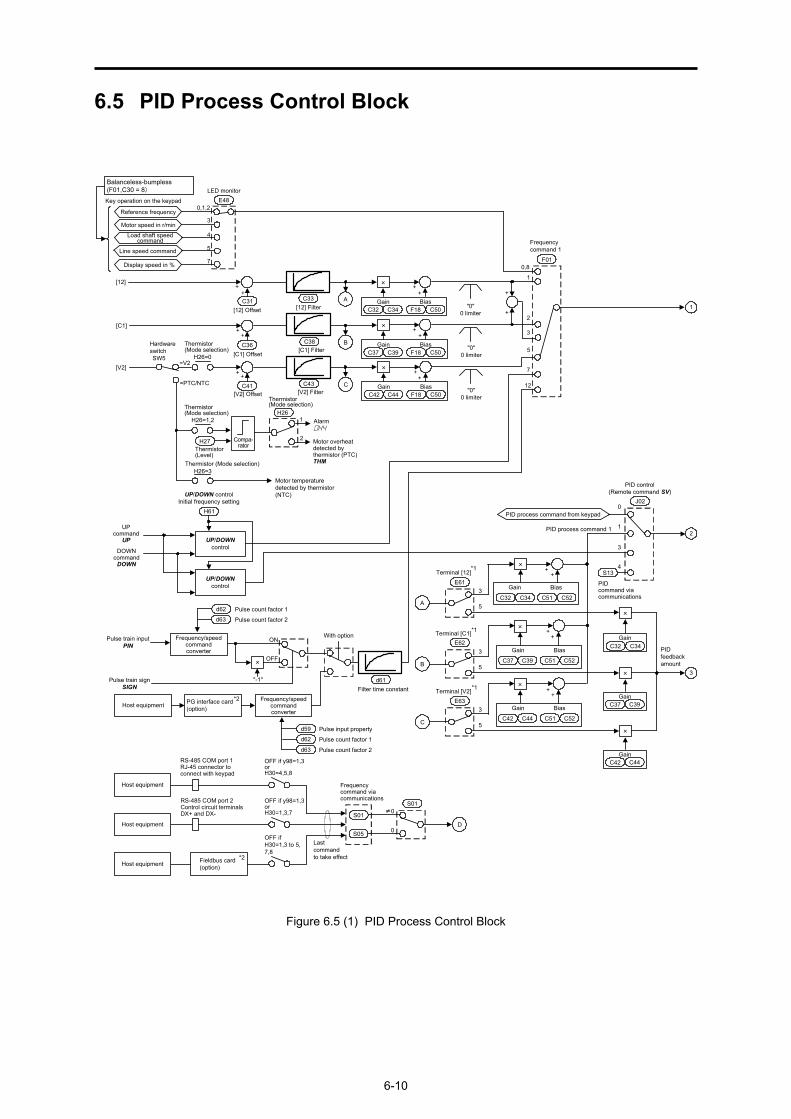
6.5 PID Process Control Block
PID process command 1
PIDcommand viacommunications
PID process command from keypad0
4
1
J02
3
++
Gain Bias
PIDfeedbackamount
Terminal [12]*1
E61
GainC34C32
C34C32 C52C51
×
×
3
5
++
Gain Bias
*1Terminal [C1]E62
GainC39C37
C39C37 C52C51
×
×
3
5
++
Gain Bias
*1Terminal [V2]E63
GainC44C42
C44C42 C52C51
×
×
3
5
S13
A
B
C
0,8
1
2
3
Frequencycommand 1
7
12
F01
+
+
"0"0 limiter
5
++
Gain Bias
×
C32 C34 F18 C50
++
Gain Bias
×
C37 C39 F18 C50
++
Gain Bias
×
C42 C44 F18 C50
A
B
C
Key operation on the keypad
LED monitor
Load shaft speedcommand
3
4
5
Reference frequency
Motor speed in r/min
Line speed command
0,1,2E48
7Display speed in %
C43
C38
C33[12] Filter
+C41
[V2] Offset
+C36
[C1] Offset
C31+
[12] Offset
+
+
[C1]
[12]+
[V2] Filter
[C1] Filter
1
2
3
Balanceless-bumpless(F01,C30 = 8)
UP/DOWNcontrol
UPcommand
UP
DOWNcommandDOWN
UP/DOWNcontrol
H61
UP/DOWN controlInitial frequency setting
[V2]
HardwareswitchSW5
Thermistor(Mode selection)
H26=0
=PTC/NTC
Motor temperaturedetected by thermistor(NTC)
Thermistor(Level)
Alarm0h4
Compa-rator
H27 Motor overheatdetected bythermistor (PTC)THM
1
2
H26=3
H26=1,2H26
≠0
0
Frequencycommand viacommunications
S01
S05Host equipment
OFF if y98=1,3orH30=1,3,7
Host equipment
Host equipment
OFF if y98=1,3orH30=4,5,8
OFF ifH30=1,3 to 5,7,8
Lastcommandto take effect
S01
*2Fieldbus card(option)
D
Pulse train inputPIN
Pulse train signSIGN
Host equipment PG interface card(option)
Frequency/speedcommandconverter
Frequency/speedcommandconverter
d62 Pulse count factor 1
d63 Pulse count factor 2
d59 Pulse input property
d61Filter time constant
d62 Pulse count factor 1
d63 Pulse count factor 2
PID control(Remote command SV)
With optionON
OFF×
"-1"
=V2
RS-485 COM port 1RJ-45 connector toconnect with keypad
RS-485 COM port 2Control circuit terminalsDX+ and DX-
Thermistor(Mode selection)
Thermistor (Mode selection)
"0"0 limiter
"0"0 limiter
*2
Thermistor(Mode selection)
Figure 6.5 (1) PID Process Control Block

6.5 PID Process Control Block
6-11
Chap. 6
BLO
CK
DIA
GR
AM
S FO
R C
ON
TRO
L LOG
IC
Jumpfrequency
Drive frequencycommand
Cancel PIDcontrolHz/PID
Frequencylimiter (Low)
Frequencylimiter (High)
C01C02C03C04
F15
F16
Inverter runningRUN
Under PID controlPID-CTL
Enablecommunicationslink via RS-485or fieldbusLE
0,2
1,3
y99Loader link function
Multi-frequency 1
Multi-frequency 2
Multi-frequency 3
C05
C06
C07
Selectmulti-frequencySS1, SS2
Manual speedcommand
0,2,6
1,3 to 5,7,8
H30 Bus link functiony98
0,2
1,3
Communicationslink function
Invert
Normal/inverseoperation
Switchnormal/InverseoperationIVS
PID control(Modeselection)
PID processor
Reset PID integral and differentialcomponentsPID-RST
Hold PID integral componentPID-HLD
PID control P (Gain)PID controlI (Integral time)PID controlD (Differential time)
Selectmulti-frequencySS4, SS8
+-Multi-frequency 4
PID control(Feedback filter)
C08
J06
J01
J05
J04
J03
PID control (Select alarm output)
PID control (Upper level alarm (AH))
PID control (Lower level alarm (AL))J13
J12
J11
PID alarmPID-ALM
PID control(Anti reset windup)
J10
Multi-frequency 8C12
Multi-frequency 12C16
D
1
2
3
PID control(Upper limit of PIDprocess output)
J18
PID control(Lower limit of PIDprocess output)
PID control (Slow flowrate level stop latency)
PID control (Starting frequency)
PID control (Stop frequency for slow flowrate)
J17
J16
J15
"0"
PID control (Pressurizing time)J09
J08PID control(Pressurizationstartingfrequency)
J19
Hz
Slow flowratestop control
PID alarmprocessor
*2 For details of the options, refer to the instruction manual for each option.
*1 Takes priority when the same function has been assigned by E61, E62 and E63: Terminal [12] > Terminal [C1] > Terminal [V2]
Note:S codes are communication-related function codes. Refer to the RS-485Communication User's Manual for details.
Figure 6.5 (2) PID Process Control Block
6-12
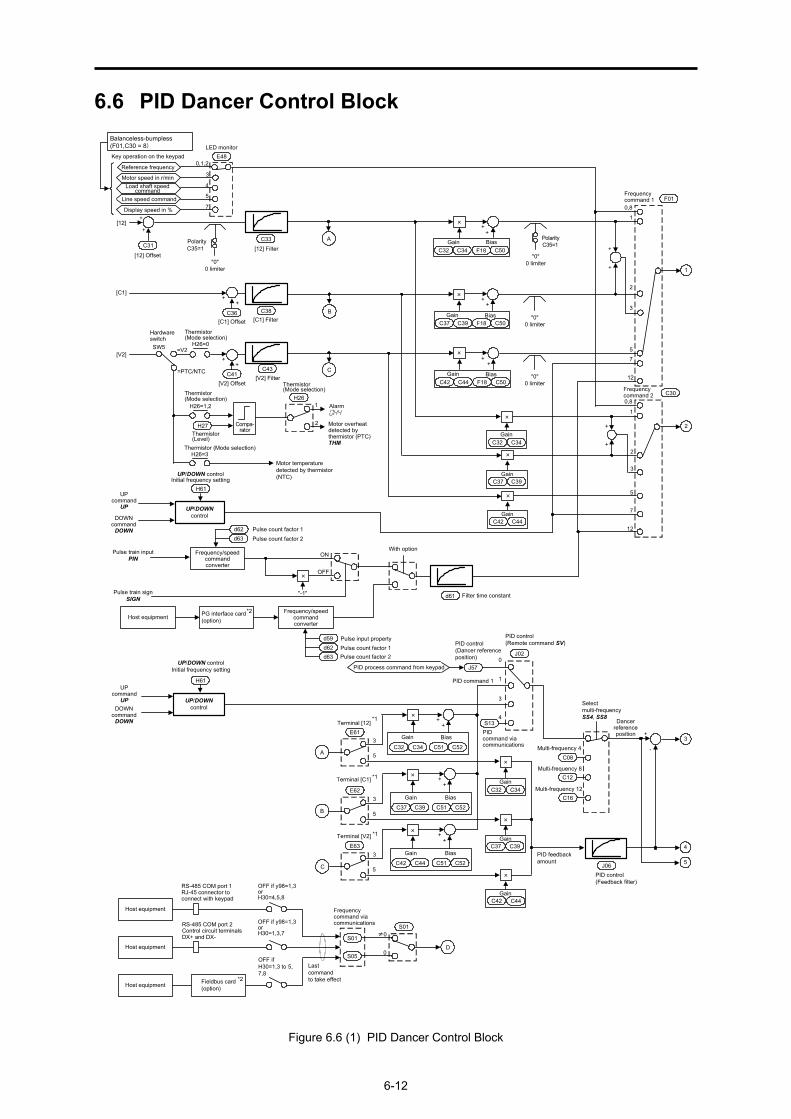
6.6 PID Dancer Control Block
+
+
+
0,8
1
2
3
5
+
+
0,8
1
2
3
Frequencycommand 2
Frequencycommand 1
5
Gain
Gain
Gain Bias
++
+
F01
C39C37
C34C32
C30
C37 C39 F18 C50"0"
0 limiter
"0"0 limiter
×
×
×
×
7
7
Gain BiasC42 C44 F18 C50
GainC44C42
×
UP/DOWNcontrol
UPcommand
UP
DOWNcommandDOWN
H61
12
12
[12]
[C1]
[C1] Filter
Key operation on the keypadLED monitor
3
4
5Line speed command
0,1,2E48
C43
C38
7Display speed in %
[V2] Filter
C31
+
++
C36[C1] Offset
++
C41[V2] Offset
+
[12] Offset"0"
0 limiter
PolarityC35=1
C33
[12] Filter
UP/DOWN controlInitial frequency setting
++
Gain BiasC32 C34 F18 C50
×
PolarityC35=1
+
-Multi-frequency 4
PID control(Feedback filter)
PID command 1
PIDcommand viacommunications
PID process command from keypad0
4
1
C08
J06
J02
3
++
Gain Bias
PID feedbackamount
Terminal [12]*1
E61
GainC34C32
C34C32 C52C51
×
×
3
5
++
Gain Bias
*1Terminal [C1]
E62
GainC39C37
C39C37 C52C51
×
×
3
5
++
Gain Bias
*1Terminal [V2]
E63
GainC44C42
C44C42 C52C51
×
×
3
5
S13
A
B
C
C12
C16
J57
PID control(Dancer referenceposition)
PID control(Remote command SV)
Selectmulti-frequencySS4, SS8
Dancerreferenceposition
UP/DOWNcontrol
UPcommandUP
DOWNcommandDOWN
H61
UP/DOWN controlInitial frequency setting
Load shaft speedcommand
Motor speed in r/min
Reference frequency
A
B
C
1
2
3
4
5
Balanceless-bumpless(F01,C30 = 8)
[V2]
HardwareswitchSW5
Thermistor(Mode selection)
H26=0
=PTC/NTC
Motor temperaturedetected by thermistor(NTC)
Thermistor(Level)
Alarm0h4
Compa-rator
H27 Motor overheatdetected bythermistor (PTC)THM
1
2
H26=3
Pulse train inputPIN
Pulse train signSIGN
Host equipment PG interface card(option)
Frequency/speedcommandconverter
Frequency/speedcommandconverter
d62 Pulse count factor 1d63 Pulse count factor 2
d59 Pulse input property
d61 Filter time constant
d62 Pulse count factor 1d63 Pulse count factor 2
H26=1,2H26
Thermistor(Mode selection)
"0"0 limiter
Thermistor (Mode selection)
≠0
0
Frequencycommand viacommunications
S01
S05Host equipment
OFF if y98=1,3orH30=1,3,7
Host equipment
Host equipment
OFF if y98=1,3orH30=4,5,8
OFF ifH30=1,3 to 5,7,8
Lastcommandto take effect
S01
*2Fieldbus card(option)
D
With optionON
OFF
=V2
"-1"
×
*2
RS-485 COM port 2Control circuit terminalsDX+ and DX-
RS-485 COM port 1RJ-45 connector toconnect with keypad
Thermistor(Mode selection)
Multi-frequency 8
Multi-frequency 12
Figure 6.6 (1) PID Dancer Control Block

6.6 PID Dancer Control Block
6-13
Chap. 6
BLO
CK
DIA
GR
AM
S FO
R C
ON
TRO
L LOG
IC
Jumpfrequency
Select frequencycommand 2/1Hz2/Hz1
Enablecommunications linkvia RS-485 or fieldbusLE
Selectmulti-frequencySS1, SS2
+
+
+
Auxiliary frequency reference 1
Auxiliary frequency reference 2
Multi-frequency 1
Multi-frequency 2
Multi-frequency 3
Frequencylimiter (Low)
Frequencylimiter (High)
Drive frequencycommand
C01C02C03C04
C05
C06
C07
GainC34C32
GainC39C37
F16
F15
×
×
×
×
GainC44C42
×
×
Communicationslink function
0,2,6
1,3 to 5,7,8 0,2
1,3
H30
y99
Bus link functiony98
0,2
1,3
Loader link function
PID processor
PID alarmprocessor
PID control (Select alarm output)
PID control (Upper level alarm (AH))
PID control (Lower level alarm (AL))J13
J12
J11
PID alarm PID-ALM
PID control(Upper limit of PIDprocess output)
J18
J19PID control(Lower limit of PIDprocess output)
J58
J03J04J05
J59J60J61
P (Gain)I (Integral time)
D (Differential time)
Reset PID integral anddifferential componentsPID-RST
PID control(Anti reset windup)
J10
J59 to J61within detection width
PID control(Detection width of dancer position deviation)
+
+
×
0
1MV (Ratio)
MV (Speed)
J62 Bit 1: PID control
×
0 1
J62
"-1"
Primaryfrequency command
Cancel PID controlHz/PID
D
Hold PID integral componentPID-HLD
1
2
3
4
5
+
0
1
2
01
2
Terminal [C1]
Terminal [12]
E62
01
*1 E63
*1
*1
Terminal [V2]
E61
A
B
C2
PID control
P (Gain) 2I (Integral time) 2
D (Differential time) 2
PID control (Select compensation factorfor PID output)
Bit 0: PID control(PID output characteristics)
*1 Takes priority when the same function has been assigned by E61, E62 and E63: Terminal [12] > Terminal [C1] > Terminal [V2]
Note:S codes are communication-related function codes. Refer to the RS-485Communication User's Manual for details.
*2 For details of the options, refer to the instruction manual for each option.
Figure 6.6 (2) PID Dancer Control Block
6-14
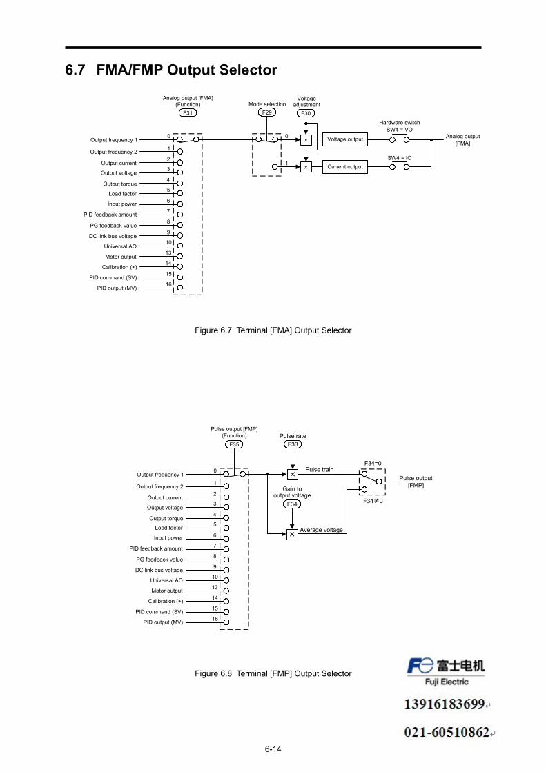
6.7 FMA/FMP Output Selector
Output frequency 1
Output frequency 2
PID output (MV)
×
× Current output
Voltage output
SW4 = IO
Hardware switchSW4 = VO
Analog output[FMA]
F31 F30
Analog output [FMA](Function)
VoltageadjustmentMode selection
F29
0
1
16
Output current2
Output voltage3
Output torque4
Load factor5
Input power 6
PID feedback amount 7
PG feedback value8
DC link bus voltage9
Universal AO10
Motor output13
Calibration (+)14
PID command (SV)15
0
1
Figure 6.7 Terminal [FMA] Output Selector
Output frequency 1
Output frequency 2
F35
Pulse output [FMP](Function)
0
1
16
Output current2
Output voltage3
Output torque4
5
6
7
8
9
10
13
14
15
Pulse output[FMP]
Pulse rateF33
×
F34=0
Gain tooutput voltage
F34
×
F34≠0
Pulse train
Average voltage
PID output (MV)
Load factor
Input power
PID feedback amount
PG feedback value
DC link bus voltage
Universal AO
Motor output
Calibration (+)
PID command (SV)
Figure 6.8 Terminal [FMP] Output Selector
Chapter 7
KEYPAD FUNCTIONS (OPERATING WITH THE KEYPAD)
This chapter describes the names and functions of the keypad and inverter operation using the keypad. The inverter features three operation modes (Running, Programming and Alarm modes) which enable you to run and stop the motor, monitor running status, set function code data, display running information required for maintenance, and display alarm data.
Contents 7.1 LED Monitor, Keys and LED Indicators on the Keypad ............................................................................ 7-1 7.2 Overview of Operation Modes.................................................................................................................... 7-4 7.3 Running Mode ............................................................................................................................................ 7-6
7.3.1 Monitoring the running status ............................................................................................................. 7-6 7.3.2 Monitoring light alarms....................................................................................................................... 7-8 7.3.3 Setting up frequency and PID commands ........................................................................................... 7-9 7.3.4 Running/stopping the motor.............................................................................................................. 7-14 7.3.5 Jogging Operation ............................................................................................................................. 7-14 7.3.6 Remote and local modes ................................................................................................................... 7-15 7.3.7 External run/frequency command ..................................................................................................... 7-16
7.4 Programming Mode .................................................................................................................................. 7-17 7.4.1 Setting up basic function codes quickly -- Menu #0 "Quick Setup" --.............................................. 7-19 7.4.2 Setting up function codes -- Menu #1 "Data Setting" --................................................................... 7-22 7.4.3 Checking changed function codes -- Menu #2 "Data Checking" -- .................................................. 7-25 7.4.4 Monitoring the running status -- Menu #3 "Drive Monitoring" -- ................................................... 7-26 7.4.5 Checking I/O signal status -- Menu #4 "I/O Checking" -- ............................................................... 7-30 7.4.6 Reading maintenance information -- Menu #5 "Maintenance Information" -- ................................ 7-35 7.4.7 Reading alarm information -- Menu #6 "Alarm Information" --...................................................... 7-40 7.4.8 Copying data -- Menu #7 "Data Copying" -- ................................................................................... 7-43
7.5 Alarm Mode .............................................................................................................................................. 7-46 7.5.1 Releasing the alarm and switching to Running mode ....................................................................... 7-46 7.5.2 Displaying the alarm history ............................................................................................................. 7-46 7.5.3 Displaying the status of inverter at the time of alarm ....................................................................... 7-46 7.5.4 Switching to Programming mode...................................................................................................... 7-46
7.6 USB Connectivity ..................................................................................................................................... 7-48


7.1 LED Monitor, Keys and LED Indicators on the Keypad
7-1
Chap. 7
KEY
PAD
FUN
CTIO
NS
7.1 LED Monitor, Keys and LED Indicators on the Keypad As shown at the right, the keypad consists of a four-digit LED monitor, six keys, and five LED indicators.
The keypad allows you to run and stop the motor, monitor the running status, specify the function code data, and monitor I/O signal states, maintenance information, and alarm information.
Figure 7.1 Keypad
Table 7.1 Overview of Keypad Functions
Item LED Monitor,
Keys, and LED Indicators
Functions
LED Monitor
Four-digit, 7-segment LED monitor which displays the followings according to the operation modes. In Running mode: Running status information (e.g., output
frequency, current, and voltage) When a light alarm occurs, l-al is displayed. In Programming mode: Menus, function codes and their data In Alarm mode: Alarm code, which identifies the alarm factor
when the protective function is activated.
Program/Reset key which switches the operation modes of the inverter. In Running mode: Pressing this key switches the inverter to
Programming mode. In Programming mode: Pressing this key switches the inverter to Running
mode. In Alarm mode: Pressing this key after removing the alarm factor
will switch the inverter to Running mode.
Function/Data key which switches the operations you want to do in each mode as follows: In Running mode: Pressing this key switches the information to be
displayed concerning the status of the inverter (output frequency (Hz), output current (A), output voltage (V), etc.).
When a light alarm is displayed, holding down this key resets the light alarm and switches back to Running mode.
In Programming mode: Pressing this key displays the function code or establishes the data entered with and keys.
In Alarm mode: Pressing this key displays the details of the problem indicated by the alarm code that has come up on the LED monitor.
RUN key. Press this key to run the motor.
STOP key. Press this key to stop the motor.
Operation Keys
and UP and DOWN keys. Press these keys to select the setting items and change the function code data displayed on the LED monitor.
RUN LED Lights when running with a run command entered by the key, by terminal command FWD or REV, or through the communications link.
LED Indicators KEYPAD
CONTROL LED
Lights when the inverter is ready to run with a run command entered by the key (F02 = 0, 2, or 3). In Programming and Alarm modes, however,
pressing the key cannot run the inverter even if this indicator lights.
LEDindicators
DOWN key
STOP key
UP key
Function/Data key
RUN key
7-segmentLED monitor
Program/Reset key
USB port
RUN LED

7-2
Table 7.1 Overview of Keypad Functions (continued)
Item LED Monitor,
Keys, and LED Indicators
Functions
These three LED indicators identify the unit of numeral displayed on the LED monitor in Running mode by combination of lit and unlit states of them. Unit: Hz, A, kW, r/min and m/min Refer to Section 7.3.1 "Monitoring the running status" for details.
Unit LEDs (3 LEDs)
While the inverter is in Programming mode, the LEDs of Hz and kW light. Hz A kW
LED Indicators
x10 LED
Lights when the data to display exceeds 9999. When this LED lights, the "displayed value x 10" is the actual value. Example: If the LED monitor displays 1234 and the x10 LED lights, it means that the actual value is "1,234 × 10 = 12,340."
USB port
The USB port with a mini B connector enables the inverter to connect with a PC with a USB cable.
7.1 LED Monitor, Keys and LED Indicators on the Keypad
7-3
Chap. 7
KEY
PAD
FUN
CTIO
NS
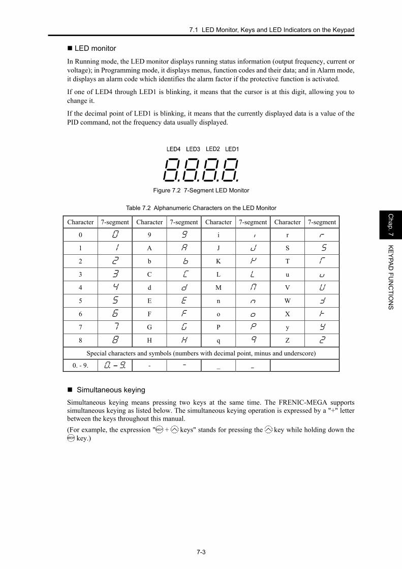
LED monitor
In Running mode, the LED monitor displays running status information (output frequency, current or voltage); in Programming mode, it displays menus, function codes and their data; and in Alarm mode, it displays an alarm code which identifies the alarm factor if the protective function is activated.
If one of LED4 through LED1 is blinking, it means that the cursor is at this digit, allowing you to change it.
If the decimal point of LED1 is blinking, it means that the currently displayed data is a value of the PID command, not the frequency data usually displayed.
Figure 7.2 7-Segment LED Monitor
Table 7.2 Alphanumeric Characters on the LED Monitor
Character 7-segment Character 7-segment Character 7-segment Character 7-segment
0 0 9 9 i i r r
1 1 A a J j S Ss
2 2 b Bb K k T T
3 3 C Cc L l u U
4 4 d d M m V u
5 5 E e n n W w
6 6 F f o o X x
7 7 G g P p y y
8 8 H h q q Z Z
Special characters and symbols (numbers with decimal point, minus and underscore)
0. - 9. * – ) - - _ _
Simultaneous keying Simultaneous keying means pressing two keys at the same time. The FRENIC-MEGA supports simultaneous keying as listed below. The simultaneous keying operation is expressed by a "+" letter between the keys throughout this manual. (For example, the expression " + keys" stands for pressing the key while holding down the
key.)

7-4
7.2 Overview of Operation Modes FRENIC-MEGA features the following three operation modes:
■ Running mode : After powered ON, the inverter automatically enters this mode. This mode allows you to specify the reference frequency, PID command
value and etc., and run/stop the motor with the / keys. It is also possible to monitor the running status in real time. If a light alarm occurs, the l-al appears on the LED monitor. ■ Programming mode : This mode allows you to configure function code data and check a variety of
information relating to the inverter status and maintenance. ■ Alarm mode : If an alarm condition arises, the inverter automatically enters Alarm mode. In
this mode, you can view the corresponding alarm code* and its related information on the LED monitor. * Alarm code: Indicates the cause of the alarm condition. For details, refer to Chapter 2,
Section 2.8 "Protective Functions" and Section 7.4.7 "Reading alarm information" in this Chapter.
Figure 7.3 shows the status transition of the inverter between these three operation modes. If the inverter is turned ON, it automatically enters Running mode, making it possible to start or stop the motor.
Programming mode
Configuration of functioncode data and monitor ofmaintenance/alarm infoand various status
Alarm mode
Display of alarm status
Occurrence ofa heavy alarm
(Press this key ifan alarm hasoccurred.)
+
Running mode
Release ofa light alarm
Monitor of running status
Light alarm displayed
Run/Stop of motor
Run/Stop of motor
Detection ofa light alarm
Power ON
Release ofa heavy alarm
Figure 7.3 Status Transition between Operation Modes

7.2 Overview of Operation Modes
7-5
Chap. 7
KEY
PAD
FUN
CTIO
NS
Figure 7.4 illustrates the transition of the LED monitor screen during Running mode, the transition between menu items in Programming mode, and the transition between alarm codes at different occurrences in Alarm mode.
(*1) The speed monitor allows you to select the desired one from the seven speed monitor items by using function code E48.
(*2) Applicable only when PID control is active (J01 = 1, 2 or 3). (*3) The Timer screen appears only when the timer operation is enabled with function code C21. (*4) Applicable only when the full-menu mode is selected (E52 = 2).
Figure 7.4 Transition between Basic Screens in Individual Operation Mode

7-6
7.3 Running Mode When the inverter is turned on, it automatically enters Running mode in which you can: (1) Monitor the running status (e.g., output frequency and output current), (2) Configure the reference frequency and other settings, (3) Run/stop the motor, (4) Jog (inch) the motor, (5) Switch between remote and local modes, and (6) Monitor light alarms
7.3.1 Monitoring the running status In Running mode, the fourteen items listed below can be monitored. Immediately after the inverter is turned on, the monitor item specified by function code E43 is displayed. Press the key to switch between monitor items.
Table 7.3 Monitoring Items
Monitor items Display
sample on the LED
monitor *1
LED indicator : on, : off Unit Meaning of displayed value
Functioncode datafor E43
Speed monitor Function code E48 specifies what to be displayed on the LED monitor and LED indicators. 0
Output frequency (before slip compensation)
5*00 Hz A kW Hz Frequency actually being output (E48 = 0)
Output frequency (after slip compensation)
5*00 Hz A kW Hz Frequency actually being output (E48 = 1)
Reference frequency 5*00 Hz A kW Hz Reference frequency being set (E48 = 2)
Motor speed 1500 Hz A kW r/minP01120× (Hz)frequency Output (E48 = 3)
Load shaft speed 30*0 Hz A kW r/min Output frequency (Hz) × E50 (E48 = 4)Line speed 30*0 Hz A kW m/min Output frequency (Hz) × E50 (E48 = 5)
Speed (%) 5*0 Hz A kW % 100x frequency Maximum
frequencyOutput (E48 = 7)
Output current 1"34 Hz A kW A Current output from the inverter in RMS 3 Output voltage *2 200u Hz A kW V Voltage output from the inverter in RMS 4
Calculated torque 50 Hz A kW % Motor output torque in % (Calculated value) 8
Input power 1*25 Hz A kW kW Input power to the inverter 9 *3, *4
PID command 1*0* Hz A kW - 10
*3, *5PID feedback amount )0* Hz A kW -
PID command/feedback amount transformed to that of virtual physical value of the object to be controlled (e.g. temperature) Refer to function codes E40 and E41 for details.
12
PID output *3, *4 10** Hz A kW % PID output in % as the maximum frequency (F03) being at 100% 14
Load factor *6 50; Hz A kW % Load factor of the motor in % as the rated output being at 100% 15
Motor output *7 )85 Hz A kW kW Motor output in kW 16
*8Analog input monitor 8"00 Hz A kW -
An analog input to the inverter in a format suitable for a desired scale. Refer to function codes E40 and E41 for details.
17
Torque current *9 48 Hz A kW % Torque current command value or calculated torque current 23
Magnetic flux command 50 Hz A kW % Magnetic flux command value
(Available only under vector control) 24
Input watt-hour (kWh) Input watt-hour 10*0 Hz A kW kWh
100 25

7.3 Running Mode
7-7
Chap. 7
KEY
PAD
FUN
CTIO
NS
*1 A value exceeding 9999 cannot be displayed as is on the 4-digit LED monitor screen, so the LED monitor displays one-tenth of the actual value with the x10 LED lit.
*2 When the LED monitor displays an output voltage, the 7-segment letter u in the lowest digit stands for the unit of the voltage "V."
*3 These PID related items appear only when the inverter drives the motor under the PID process control specified by function code J01 (= 1, 2 or 3).
*4 When the LED monitor displays a PID command or its output amount, the dot (decimal point) attached to the lowest digit of the 7-segment letter blinks.
*5 When the LED monitor displays a PID feedback amount, the dot (decimal point) attached to the lowest digit of the 7-segment letter lights.
*6 When the LED monitor displays a load factor, the 7-segment letter ; in the lowest digit stands for "%." *7 When the LED monitor displays the motor output, the unit LED indicator "kW" blinks. *8 The analog input monitor can appear only when the analog input monitor function is assigned to any of the analog
input terminals by any of function codes E61 to E63 (= 20). *9 A torque current value appears only when the vector control is selected (F42 = 6).
Function code E42 (LED display filter) allows you to filter the monitoring signals for the monitor items such as output frequency and output current. Increase the E42 data if the monitored values are unstable and unreadable due to fluctuation of load.

7-8
7.3.2 Monitoring light alarms The FRENIC-MEGA identifies abnormal states in two categories--Heavy alarm and Light alarm. If the former occurs, the inverter immediately trips; if the latter occurs, the inverter shows the l-al on the LED monitor and blinks the KEYPAD CONTROL LED but it continues to run without tripping.
Which abnormal states are categorized as a light alarm ("Light alarm" object) should be defined with function codes H81 and H82 beforehand.
Assigning the LALM signal to any one of the digital output terminals with any of function codes E20 to E24 and E27 (= 98) enables the inverter to output the LALM signal on that terminal upon occurrence of a light alarm.
For details of the light alarm objects, refer to Chapter 2, Section 2.8 "Protective Functions."
■ How to check a light alarm factor
If a light alarm occurs, l-al appears on the LED monitor. To check the current light alarm factor, enter Programming mode by pressing the key and select 5_36 on Menu #5 "Maintenance Information."
It is also possible to check the factors of the last three light alarms 5_37 (last) to 5_39 (3rd last).
For details of the menu transition of the maintenance information, refer to Section 7.4.6 "Reading maintenance information."
■ How to reset a light alarm
After checking the current light alarm factor, to switch the LED monitor from the l-al indication state back to the running status display (e.g., output frequency), press the key in Running mode.
If the light alarm factor has been removed, the KEYPAD CONTROL LED stops blinking and the LALM signal turns OFF. If not (e.g. DC fan lock), the KEYPAD CONTROL LED continues blinking and the LALM signal remains ON.
7.3 Running Mode
7-9
Chap. 7
KEY
PAD
FUN
CTIO
NS
7.3.3 Setting up frequency and PID commands You can set up the desired frequency and PID commands by using and keys on the keypad. It is also possible to set up the frequency command as load shaft speed, motor speed or speed (%) by setting function code E48.
■ Setting up a frequency command Using the keypad (F01 = 0 (factory default) or 8)
(1) Set function code F01 to "0" or "8." This can be done only when the inverter is in Running mode.
(2) Press the / key to display the current reference frequency. The lowest digit will blink.
(3) To change the reference frequency, press the / key again. To save the new setting into the inverter's memory, press the key (when E64 = 1 (factory default)). When the power is turned ON next time, the new setting will be used as an initial reference frequency.
• In addition to the saving with the key described above, auto-saving is also available
(when E64 = 0). • If you have set function code F01 to "0" or "8" but have selected a frequency command
source other than frequency command 1 (i.e., frequency command 2, frequency command via communication, or multi-frequency command), then the and keysare disabled to change the current frequency command even in Running mode. Pressing either of these keys just displays the current reference frequency.
• When you start specifying the reference frequency or any other parameter with the / key, the least significant digit on the display blinks; that is, the cursor lies in the least
significant digit. Holding down the / key changes data in the least significant digit and generates a carry, while the cursor remains in the least significant digit.
• After the least significant digit blinks by pressing the / key, holding down the key for more than 1 second moves the cursor from the least significant digit to the most significant digit. Further holding it down moves the cursor to the next lower digit. This cursor movement allows you to easily move the cursor to the desired digit and change the data in higher digits.
• Setting F01 data to "8" enables the balanceless-bumpless switching. When the frequency command source is switched to the keypad from any other source, the inverter inherits the current frequency that has applied before switching, providing smooth switching and shockless running.
Using analog input (F01 = 1 to 3, or 5) • Applying the gain and bias to analog inputs (voltage inputs to terminals [12] and [V2], and current
input to terminal [C1]) enables the frequency to be set within an arbitrary range (frequency vs. analog input level).
(Refer to the description of F18.) • Noise reduction filters are applicable to these analog inputs. (Refer to the descriptions of C33, C38 and C43.) • The normal/inverse operation for the frequency command 1 setting (F01) can be selected with
function code C53 and be switched between them with the terminal command IVS assigned to any of the digital input terminals.
(Refer to the descriptions of E01 through E09.)
7-10
• To input bipolar analog voltage (0 to ±10 VDC) to terminals [12] and [V2], set C35 and
C45 data to "0." Setting C35 and C45 data to "1" enables the voltage range from 0 to +10 VDC and interprets the negative polarity input from 0 to -10 VDC as 0 V.
• A reference frequency can be specified not only with the frequency (Hz) but also with other menu items, depending on the setting of function code E48 (= 3 to 5, or 7).
■ Settings under PID process control To enable the PID process control, you need to set the J01 data to "1" or "2." Under the PID control, the items that can be specified or checked with and keys are different from those under regular frequency control, depending upon the current LED monitor setting. If the LED monitor is set to the speed monitor (E43 = 0), you can access manual speed commands (frequency command) with and keys; if it is set to any other, you can access the PID process command with those keys.
Setting the PID process command with and keys (1) Set function code J02 to "0: / keys on keypad." (2) Set the LED monitor to something other than the speed monitor (E43=0) when the inverter is in
Running mode. When the keypad is in Programming or Alarm mode, you cannot modify the PID process command with the / key. To enable the PID process command to be modified with the / key, first switch to Running mode.
(3) Press the / key to display the PID process command. The lowest digit and its decimal point blinks on the LED monitor.
(4) To change the PID process command, press the / key again. The PID process command you have specified will be automatically saved into the inverter’s internal memory. It is retained even if you temporarily switch to another PID process command source and then go back to the via-keypad PID process command. Also, it is retained in the memory even while the inverter is powered off, and will be used as the initial PID process command next time the inverter is powered on.
• Even if multi-frequency is selected as a PID process command (SS4 or SS8 = ON), you
still can set the process command using the keypad. • When function code J02 is set to any value other than "0," pressing the / key
displays, on the 7-segment LED monitor, the PID process command currently selected, while you cannot change the setting.
• On the 7-segment LED monitor, the decimal point of the lowest digit is used to characterize what is displayed. The decimal point of the lowest digit blinks when a PID process command is displayed; the decimal point lights when a PID feedback amount is displayed.

7.3 Running Mode
7-11
Chap. 7
KEY
PAD
FUN
CTIO
NS
Table 7.4 PID Process Command Manually Set with / Key and Requirements
PID control (Mode
selection) J01
PID control (Remote command
SV) J02
LED MonitorE43
Multi- frequency SS4, SS8
With / key
0 PID process command by keypad1 or 2
Other than 0 Other than 0 ON or OFF PID process command currently
selected
Setting up the frequency command with and keys under PID process control When function code F01 is set to "0" ( / keys on keypad) and frequency command 1 is selected as a manual speed command (when disabling the frequency setting command via communications link or multi-frequency command), switching the LED monitor to the speed monitor in Running mode enables you to modify the frequency command with the / keys. In Programming or Alarm mode, the / keys are disabled to modify the frequency command. You need to switch to Running mode. Table 7.5 lists the combinations of the commands and the figure illustrates how the manual speed command entered via the keypad is translated to the final frequency command .
The setting procedure is the same as that for setting of a usual frequency command.
Table 7.5 Manual Speed (Frequency) Command Specified with / Keys and Requirements
PID control (Mode selection) J01
LED monitor E43
Frequency command 1 F01
Multi- frequency SS2
Multi- frequency SS1
Communi-cations link operation LE
Cancel PID control Hz/PID
Pressing / keys controls:
OFF (PID enabled)
PID output (as final frequency command)
0 OFF OFF OFF ON (PID disabled)
Manual speed (frequency) command set by keypad
OFF (PID enabled)
PID output (as final frequency command)
1 or 2 0
Other than the above ON (PID disabled)
Manual speed (frequency) command currently selected

7-12
■ Settings under PID dancer control To enable the PID dancer control, you need to set the J01 data to "3." Under the PID control, the items that can be specified or checked with and keys are different from those under the regular frequency control, depending upon the current LED monitor setting. If the LED monitor is set to the speed monitor (E43 = 0), the item accessible is the primary frequency command; if it is set to any other data, it is the PID dancer position command.
Setting the PID dancer position command with the and keys (1) Set the J02 data to "0: / keys on keypad." (2) Set the LED monitor to something other than the speed monitor (E43=0) when the inverter is in
Running mode. When the keypad is in Programming or Alarm mode, you cannot modify the PID command with the / key. To enable the PID dancer position command to be modified with the / key, first switch to Running mode.
(3) Press the / key to display the PID dancer position command. The lowest digit blinks on the LED monitor.
(4) To change the command, press the / key again. The command you have specified will be automatically saved into the inverter’s internal memory as function code J57 data. It is retained even if you temporarily switch to another PID command source and then go back to the via-keypad PID command. Furthermore, you can directly configure the command with function code J57.
• Even if multi-frequency is selected as a PID command (SS4 or SS8 = ON), you still can
set the PID dancer position command using the keypad. • When the J02 data is set to any value other than "0," pressing the / key displays, on
the 7-segment LED monitor, the PID command currently selected, while you cannot change the setting.
• On the 7-segment LED monitor, the decimal point of the lowest digit is used to discriminate the PID related data from the reference command. The decimal point blinks or lights when a PID command or PID feedback amount is displayed, respectively.
Table 7.6 PID Command Manually Set with / Key and Requirements
PID control (Mode
selection) J01
PID control (Remote command
SV) J02
LED monitorE43
Multi- frequency SS4, SS8
With / key
0 PID command by keypad 3
Other than 0 Other than 0 ON or OFF
PID command currently selected

7.3 Running Mode
7-13
Chap. 7
KEY
PAD
FUN
CTIO
NS
Setting up the primary frequency command with and keys under PID dancer control When function code F01 is set to "0" ( / keys on keypad) and frequency command 1 is selected as a primary frequency command (when disabling the frequency setting command via communications link and multi-frequency command), switching the LED monitor to the speed monitor in Running mode enables you to modify the frequency command with the / keys. In Programming or Alarm mode, the / keys are disabled to modify the frequency command. You need to switch to Running mode. Table 7.7 lists the combinations of the commands and the figure illustrates how the primary frequency command entered via the keypad is translated to the final frequency command .
The setting procedure is the same as that for setting of a usual frequency command.
Table 7.7 Primary Frequency Command Specified with / Keys and Requirements
PID control (Mode selection) J01
LED monitor E43
Frequency command 1 F01
Multi- frequency SS2
Multi- frequency SS1
Communi-cations link operation LE
Cancel PID control Hz/PID
Pressing / keys controls:
OFF (PID enabled)
Final frequency command modified by PID output
0 OFF OFF OFF ON (PID disabled)
Keypad primary command (Frequency)
OFF (PID enabled)
Final frequency command modified by PID output
3 0
Other than the above ON (PID disabled)
Current primary command (Frequency)
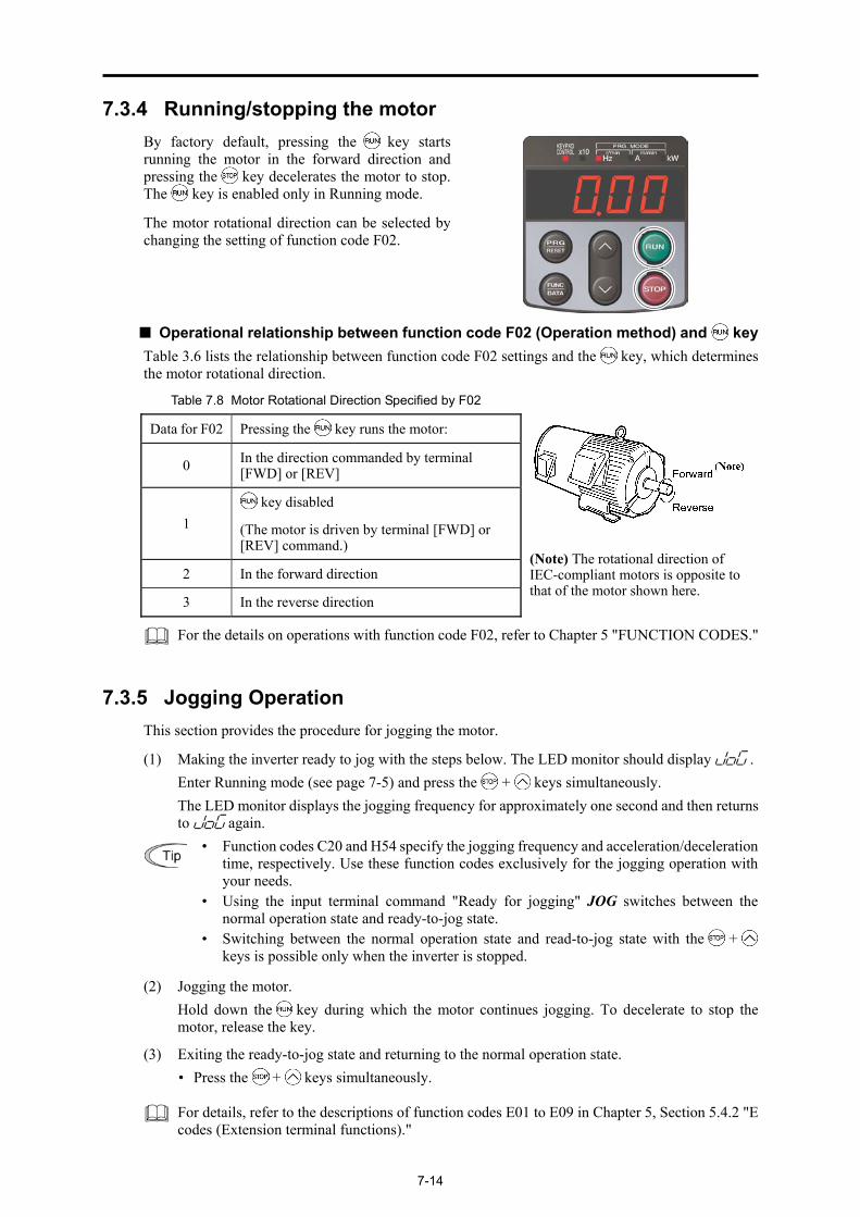
7-14
7.3.4 Running/stopping the motor By factory default, pressing the key startsrunning the motor in the forward direction andpressing the key decelerates the motor to stop. The key is enabled only in Running mode.
The motor rotational direction can be selected bychanging the setting of function code F02.
■ Operational relationship between function code F02 (Operation method) and key Table 3.6 lists the relationship between function code F02 settings and the key, which determines the motor rotational direction.
Table 7.8 Motor Rotational Direction Specified by F02
Data for F02 Pressing the key runs the motor:
0 In the direction commanded by terminal [FWD] or [REV]
1 key disabled
(The motor is driven by terminal [FWD] or [REV] command.)
2 In the forward direction
3 In the reverse direction
(Note) The rotational direction of IEC-compliant motors is opposite to that of the motor shown here.
For the details on operations with function code F02, refer to Chapter 5 "FUNCTION CODES."
7.3.5 Jogging Operation This section provides the procedure for jogging the motor.
(1) Making the inverter ready to jog with the steps below. The LED monitor should display jog . Enter Running mode (see page 7-5) and press the + keys simultaneously. The LED monitor displays the jogging frequency for approximately one second and then returns
to jog again.
• Function codes C20 and H54 specify the jogging frequency and acceleration/deceleration
time, respectively. Use these function codes exclusively for the jogging operation withyour needs.
• Using the input terminal command "Ready for jogging" JOG switches between the normal operation state and ready-to-jog state.
• Switching between the normal operation state and read-to-jog state with the + keys is possible only when the inverter is stopped.
(2) Jogging the motor. Hold down the key during which the motor continues jogging. To decelerate to stop the
motor, release the key.
(3) Exiting the ready-to-jog state and returning to the normal operation state. • Press the + keys simultaneously.
For details, refer to the descriptions of function codes E01 to E09 in Chapter 5, Section 5.4.2 "E
codes (Extension terminal functions)."

7.3 Running Mode
7-15
Chap. 7
KEY
PAD
FUN
CTIO
NS
7.3.6 Remote and local modes The inverter is available in either remote or local mode. In the remote mode that applies to ordinary operation, the inverter is driven under the control of the data settings stored in the inverter, whereas in the local mode that applies to maintenance operation, it is separated from the control system and is driven manually under the control of the keypad.
• Remote mode: Run and frequency commands are selected by function codes or source switching signals except "Select local (keypad) operation" LOC.
• Local mode: The command source is the keypad, regardless of the settings specified by function codes. The keypad takes precedence over the settings specified by communications link operation signals.
Run commands from the keypad in local mode The table below shows the input procedures of run commands from the keypad in the local mode.
When Data for F02 (run command) is : Input Procedures of Run Commands from Keypad
0: Enable / keys on keypad (Motor rotational direction from
digital terminals [FWD]/[REV])
Pressing the key runs the motor in the direction specified by command FWD or REV assigned to terminal [FWD] or [REV], respectively. Pressing the key stops the motor.
1: Enable terminal command FWD/REV
2: Enable / keys on keypad (Forward)
Pressing the key runs the motor in the forward direction only. Pressing the key stops the motor.
No specification of the motor rotational direction is required.
3: Enable / keys on keypad (Reverse)
Pressing the key runs the motor in the reverse direction only. Pressing the key stops the motor.
No specification of the motor rotational direction is required.
Switching between remote and local modes The remote and local modes can be switched by a digital input signal provided from the outside of the inverter.
To enable the switching, you need to assign LOC as a digital input signal to any of terminals [X1] to [X9] by setting "35" to any of E01 to E09, E98 and E99.
Switching from remote to local mode automatically inherits the frequency settings used in remote mode. If the motor is running at the time of the switching from remote to local, the run command will be automatically turned ON so that all the necessary data settings will be carried over. If, however, there is a discrepancy between the settings used in remote mode and ones made on the keypad (e.g., switching from the reverse rotation in remote mode to the forward rotation only in local mode), the inverter automatically stops.
The transition paths between remote and local modes depend on the current mode and the value (ON/OFF) of LOC, as shown in the status transition diagram given below. Also, refer to above table for details
Transition between Remote and Local Modes by LOC

7-16
7.3.7 External run/frequency command By factory default, run and frequency commands are sourced from the keypad. This section provides other external command source samples--an external potentiometer (variable resistor) as a frequency command source and external run switches as run forward/reverse command sources.
Set up those external sources using the following procedure.
(1) Configure the function codes as listed below.
Function code
Name Data Factory default
f 01 Frequency command 1 1: Analog voltage input to terminal [12] 0
f 02 Operation method 1: External digital input signal 2
e 98 Terminal [FWD] function 98: Run forward command FWD 98
e 99 Terminal [REV] function 99: Run reverse command REV 99
If terminal [FWD] and [REV] are ON, the F02 data cannot be changed. First turn those terminals OFF and then change the F02 data.
(2) Wire the potentiometer to terminals across [13], [12], and [11].
(3) Connect the run forward switch between terminals [FWD] and [CM] and the run reverse switch between [REV] and [CM].
(4) To start running the inverter, rotate the potentiometer to give a voltage to terminal [12] and then turn the run forward or reverse switch ON (short-circuit).
For precautions in wiring, refer to Chapter 2 "SPECIFICATIONS."
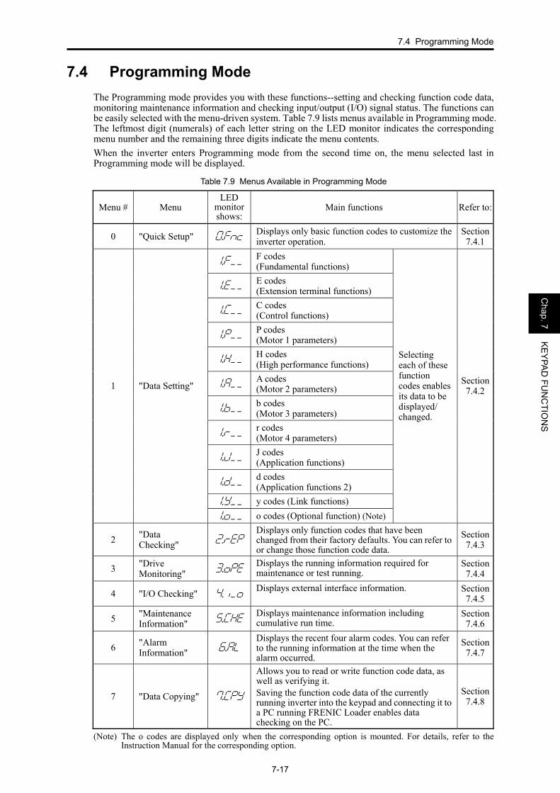
7.4 Programming Mode
7-17
Chap. 7
KEY
PAD
FUN
CTIO
NS
7.4 Programming Mode The Programming mode provides you with these functions--setting and checking function code data, monitoring maintenance information and checking input/output (I/O) signal status. The functions can be easily selected with the menu-driven system. Table 7.9 lists menus available in Programming mode. The leftmost digit (numerals) of each letter string on the LED monitor indicates the corresponding menu number and the remaining three digits indicate the menu contents. When the inverter enters Programming mode from the second time on, the menu selected last in Programming mode will be displayed.
Table 7.9 Menus Available in Programming Mode
Menu # Menu LED
monitor shows:
Main functions Refer to:
0 "Quick Setup" *fn:Displays only basic function codes to customize the inverter operation.
Section 7.4.1
!f__ F codes (Fundamental functions)
!e__ E codes (Extension terminal functions)
!c__ C codes (Control functions)
!p__ P codes (Motor 1 parameters)
!h__ H codes (High performance functions)
!a__ A codes (Motor 2 parameters)
!b__ b codes (Motor 3 parameters)
!r__ r codes (Motor 4 parameters)
!j__ J codes (Application functions)
!d__ d codes (Application functions 2)
!y__ y codes (Link functions)
1 "Data Setting"
!o__ o codes (Optional function) (Note)
Selecting each of these function codes enables its data to be displayed/ changed.
Section 7.4.2
2 "Data Checking" "rep
Displays only function codes that have been changed from their factory defaults. You can refer to or change those function code data.
Section 7.4.3
3 "Drive Monitoring" #ope
Displays the running information required for maintenance or test running.
Section 7.4.4
4 "I/O Checking" $i_oDisplays external interface information. Section
7.4.5
5 "Maintenance Information" %che
Displays maintenance information including cumulative run time.
Section 7.4.6
6 "Alarm Information" &al
Displays the recent four alarm codes. You can refer to the running information at the time when the alarm occurred.
Section 7.4.7
7 "Data Copying" 'cpy
Allows you to read or write function code data, as well as verifying it. Saving the function code data of the currently running inverter into the keypad and connecting it to a PC running FRENIC Loader enables data checking on the PC.
Section 7.4.8
(Note) The o codes are displayed only when the corresponding option is mounted. For details, refer to the
Instruction Manual for the corresponding option.
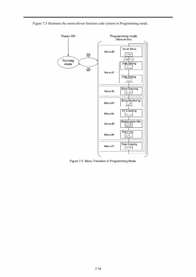
7-18
Figure 7.5 illustrates the menu-driven function code system in Programming mode.
Figure 7.5 Menu Transition in Programming Mode

7.4 Programming Mode
7-19
Chap. 7
KEY
PAD
FUN
CTIO
NS
■ Selecting menus to display The menu-driven system allows you to cycle through menus. To cycle through necessary menus only for simple operation, use function code E52 that provides a choice of three display modes as listed below. The factory default (E52 = 0) is to display only three menus--Menu #0 "Quick Setup," Menu #1 "Data Setting" and Menu #7 "Data Copying," allowing no switching to any other menu.
Table 7.10 Keypad Display Mode Selection – Function Code E52
Data for E52 Mode Menus selectable
0 Function code data editing mode (factory default) Menu #0 "Quick Setup" Menu #1 "Data Setting" Menu #7 "Data Copying"
1 Function code data check mode Menu #2 "Data Checking" Menu #7 "Data Copying"
2 Full-menu mode Menus #0 through #7
Press the key to enter Programming mode and display menus. While cycling through the menus with the / key, select the desired menu item with the key. Once the entire menu has been cycled through, the display returns to the first menu item.
7.4.1 Setting up basic function codes quickly -- Menu #0 "Quick Setup" --
Menu #0 "Quick Setup" in Programming mode allows you to quickly display and set up a basic set of function codes.
To use Menu #0 "Quick Setup," you need to set function code E52 to "0" (Function code data editing mode) or "2" (Full-menu mode).
The predefined set of function codes that are subject to quick setup are held in the inverter.

7-20
Listed below are the function codes (including those not subject to quick setup) available on the FRENIC-MEGA. A function code is displayed on the LED monitor on the keypad in the following format:
Table 7.11 Function Codes Available on FRENIC-MEGA
Function Code Group Function Codes Function Description
F codes F00 to F80 Fundamental functions Functions concerning basic motor running
E codes E01 to E99 Extension terminal functions
Functions concerning the assignment of control circuit terminals Functions concerning the display of the LED monitor
C codes C01 to C53 Control functions Functions associated with frequency settings
P codes P01 to P99 Motor 1 parameters Functions for setting up characteristics parameters (such as capacity) of the motor
H codes H03 to H98 High performance functions
Highly added-value functions Functions for sophisticated control
A codes A01 to A56 Motor 2 parameters Functions for setting up characteristics parameters (such as capacity) of the motor
b codes b01 to b56 Motor 3 parameters Functions for setting up characteristics parameters (such as capacity) of the motor
r codes r01 to r56 Motor 4 parameters Functions for setting up characteristics parameters (such as capacity) of the motor
J codes J01 to J96 Application functions 1 Functions for applications such as PID control
d codes d01 to d63 Application functions 2 Functions for applications such as speed control
y codes y01 to y99 Link functions Functions for controlling communication
o codes o27 to o59 Optional functions Functions for options (Note)
(Note) The o codes are displayed only when the corresponding option is mounted. For details of the o codes, refer to the Instruction Manual for the corresponding option.
For the list of function codes subject to quick setup and their descriptions, refer to Chapter 5
"FUNCTION CODES."
Function codes requiring simultaneous keying To modify the data for function code F00 (Data Protection), H03 (Data Initialization), H45 (Mock Alarm), or H97 (Clear Alarm Data), simultaneous keying is needed, involving the + keys or + keys.
Function code group ID number in each function code group

7.4 Programming Mode
7-21
Chap. 7
KEY
PAD
FUN
CTIO
NS
Changing, validating, and saving function code data when the inverter is running Some function code data can be changed while the inverter is running, whereas others cannot. Further, depending on the function code, modifications may or may not validate immediately. For details, refer to the "Change when running" column in Chapter 5, Section 5.2 " Function Code Tables."
For details of function codes, refer to Chapter 5, Section 5.2 " Function Code Tables."
Figure 7.6 shows the menu transition in Menu #0 "Quick Setup."
Figure 7.6 Menu Transition in Menu #0 "Quick Setup"

7-22
Basic key operation This section gives a description of the basic key operation in "Quick Setup," following the example of the function code data changing procedure shown in Figure 7.6. This example shows you how to change function code F01 data (Frequency command source) from the factory default " / keys on keypad (F01 = 0)" to "Current input to terminal [C1] (C1 function) (4 to 20 mA DC) (F01 = 2)." (1) Turn the inverter ON. It automatically enters Running mode. In that mode, press the key to
switch to Programming mode. The function selection menu appears. (In this example, *fn: is displayed.)
(2) If anything other than *fn: is displayed, use the and keys to display *fn:.
(3) Press the key to proceed to the list of function codes.
(4) Use the and keys to display the desired function code (f 01 in this example), then press the key. The data of this function code appears. (In this example, data 0 of f 01 appears.)
(5) Change the function code data using the and keys. (In this example, press the key two times to change data 0 to 2.)
(6) Press the key to establish the function code data. The saue appears and the data will be saved in the memory inside the inverter. The display will return to the function code list, then move to the next function code. (In this example, f 02.)
Pressing the key instead of the key cancels the change made to the data. The data reverts to the previous value, the display returns to the function code list, and the original function code reappears.
(7) Press the key to return to the menu from the function code list.
Cursor movement You can move the cursor when changing function code data by holding down the key for 1 second or longer in the same way as with the frequency settings. This action is called "Cursor movement."
It is possible to change or add function code items subject to quick setup. For details, consult your Fuji Electric representatives.
7.4.2 Setting up function codes -- Menu #1 "Data Setting" -- Menu #1 "Data Setting" (!f__ through!y__) in Programming mode allows you to set up all function codes. To set function codes in this menu, it is necessary to set function code E52 to "0" (Function code data editing mode) or "2" (Full-menu mode). Figure 7.7 shows the menu transition in Menu #1 "Data Setting."

7.4 Programming Mode
7-23
Chap. 7
KEY
PAD
FUN
CTIO
NS
Figure 7.7 Menu Transition in Menu #1 "Data Setting"

7-24
Basic key operation The basic key operation in Menu #1 "Data Setting" is just like that in Menu #0 "Quick Setup." (1) Turn the inverter ON. It automatically enters Running mode. In that mode, press the key to
switch to Programming mode. The function selection menu appears.
(2) Use the and keys to display the desired function code group from the choices !f__ through !y__.
(3) Press the key to proceed to the list of function codes for the selected function code group.
(4) Use the and keys to display the desired function code, then press the key. The data of this function code appears.
(5) Change the function code data using the and keys.
(6) Press the key to establish the function code data. The saue appears and the data will be saved in the memory inside the inverter. The display will return to the function code list, then move to the next function code.
Pressing the key instead of the key cancels the change made to the data. The data reverts to the previous value, the display returns to the function code list, and the original function code reappears.
(7) Press the key to return to the menu from the function code list.

7.4 Programming Mode
7-25
Chap. 7
KEY
PAD
FUN
CTIO
NS
7.4.3 Checking changed function codes -- Menu #2 "Data Checking" -- Menu #2 "Data Checking" in Programming mode allows you to check function codes that have been changed. Only the function codes whose data has been changed from the factory defaults are displayed on the LED monitor. You can refer to the function code data and change it again if necessary. To check function codes in Menu #2 "Data Checking," it is necessary to set function code E52 to "1" (Function code data check mode) or "2" (Full-menu mode). Figure 7.8 shows the menu transition in Menu #2 "Data Checking."
Figure 7.8 Menu Transition in Menu #2 "Data Checking" (Changing F01, F05 and E52 data only)
Basic key operation For details of the basic key operation, refer to Menu #0 "Quick Setup" in Section 7.4.1.

7-26
7.4.4 Monitoring the running status -- Menu #3 "Drive Monitoring" -- Menu #3 "Drive Monitoring" is used to monitor the running status during maintenance and trial running. The display items for "Drive Monitoring" are listed in Table 7.12. Figure 7.9 shows the menu transition in Menu #3 "Drive Monitoring."
Figure 7.9 Menu Transition in Menu #3 "Drive Monitoring"
Basic key operation To monitor the running status in "Drive monitoring," set function code E52 to "2" (Full-menu mode) beforehand. (1) Turn the inverter ON. It automatically enters Running mode. In that mode, press the key to
switch to Programming mode. The function selection menu appears. (In this example, *fn: is displayed.)
(2) Use the and keys to display "Drive Monitoring" (#ope ).
(3) Press the key to proceed to a list of monitoring items (e.g. 3_00 ).
(4) Use the and keys to display the desired monitoring item, then press the key. The running status information for the selected item appears.
(5) Press the key to return to the list of monitoring items. Press the key again to return to the menu.

7.4 Programming Mode
7-27
Chap. 7
KEY
PAD
FUN
CTIO
NS
Table 7.12 Drive Monitor Display Items
LED monitor shows:
Item Unit Description
3_00 Output frequency Hz Output frequency before slip compensation
3_01 Output frequency Hz Output frequency after slip compensation
3_02 Output current A Output current
3_03 Output voltage V Output voltage
3_04 Calculated torque % Calculated output torque of the motor in %
3_05 Reference frequency
Hz Frequency specified by a frequency command
3_06 Rotational direction
N/A Rotational direction being outputted f: forward, r: reverse, ----: stop
3_07
Running status N/A Running status in 4-digit hexadecimal format Refer to " Displaying running status (3_07) and running status 2 (3_23)" on the next page.
3_08
Motor speed r/minpoles) of (No.
120×Hz)frequency (Output lueDisplay va =
If the value is 10000 or lager, the x10 LED turns ON and the LED monitor shows one-tenth of the value.
3_09
Load shaft speed r/min Display value = (Output frequency Hz) × (Function code E50: Coefficient for speed indication)
If the value is 10000 or lager, the x10 LED turns ON and the LED monitor shows one-tenth of the value.
3_10
PID command value
N/A Virtual physical value (e.g., temperature or pressure) of the object to be controlled, which is converted from the PID command value using function code E40 and E41 data (PID display coefficients A and B) Display value = (PID command value) × (Coefficient A - B) + BIf PID control is disabled, "----" appears.
3_11
PID feedback amount
N/A Virtual physical value (e.g., temperature or pressure) of the object to be controlled, which is converted from the PID feedback amount using function code E40 and E41 data (PID display coefficients A and B) Display value = (PID feedback amount) × (Coefficient A - B) + BIf PID control is disabled, "----" appears.
3_12 Torque limit value (Level 1)
% Driving torque limit value A (based on motor rated torque)
3_13 Torque limit value (Level 2)
% Braking torque limit value B (based on motor rated torque)
3_14 Ratio setting % When this setting is 100%, the LED monitor shows 1.00 time of
the value to be displayed. If no ratio setting is selected, "----" appears.
3_15
Line speed m/min Display value = (Output frequency Hz) × (Function code E50: Coefficient for speed indication) If the value is 10000 or lager, the x10 LED turns ON and the LED monitor shows one-tenth of the value.