communications - americanradiohistory.comamericanradiohistory.com/.../radionics-1943-10.pdf ·...
TRANSCRIPT

.

ELECTRONICS RADAR COMMUNICATIONS TELEVISION
RESEARCH MAINTENANCE
01cTaaH,R 9 4 3 VOLUME I NUMBER 4
X-RAYS IN INDUSTRY J. L. Bach and H. W. Pickett 3
PRIVACY SYSTEMS John Keene Major 6
HIGH-SPEED PHOTOGRAPHIC EXPOSURES 9
RESPONSE TESTING WITH SQUARE WAVES Milton S. Kiver IO
THE NATURE OF COSMIC -RAY PARTICLES Dr. Marcel Schein 13
MASS SPECTROMETER 18
THYRATRONS --FOR HEAT CONTROL C. B. Stadum 19
TWO ELECTRODE GLOW -DISCHARGE TUBE
CIRCUITS Nicholas Langer 22
INDUSTRIAL REVIEW 26
PERSONALS 28
TECHNICAL BOOKS 30
NEW PRODUCTS 32
WASHINGTON BRIEFS 34
COVER PHOTO-BY WESTINGHOUSE
Electronic tubes similar to the one illustrated have the ability to amplify, generate, control, transform or convert electrical energy in almost any manner desired. Such tubes vary in size and capacity from those capable of detecting infinitesimal currents, to giant tank - like rectifiers handling thousands of amperes in power conversion. In any electronic device tubes are the heart and brain of the circuit. The development of new tubes, with new and different characteristics. will still further expand the usefulness of radionics in all industries.
EDITORIAL THE RADIO AND ELECTRONIC
ENGINEER has played a major role in establishing new records of pro- duction and in the design and improve- ment of items vitally needed to meet the ever increasing demand of the military. Without the untiring efforts of this group of men it would not have been possible for the United States to surpass the high rate of production en- joyed by its enemies. These men have established themselves firmly in Amer- ican industry. They are no longer just "slide rule" artists. They have become much more important! It is an estab- lished fact that the engineer of today occupies a commanding position in in- dustry. This is particularly true in the radio and electronic fields. By working in conjunction with military personnel they have found that not only must they specialize in their own particular line of endeavor, but they must understand in general the very function of conducting a manufactur- ing business. The engineer is being rapidly drawn into the administrative end of the business. It is only nat- ural that this should occur. Those who have conducted the operating end of various plants have found that the judgment of the engineering staff is very often the deciding factor when decisions are made as to the future conduct of the establishment. Many engineers are called upon for consulta- tion with personnel of the sales de- partments. It is logical then to as- sume that his knowledge will broaden considerably and will become very familiar with sales problems. It is quite apparent however that the aver- age engineer does not realize that he is becoming more and more important to the postwar period. It is true that many of the better equipped men will find themselves well up on top on the roster of our large radio and electronic manufacturing plants. These men will not get there by accident. By analyz- ing the entire sales possibilities the en- gineer of today certainly will be in a position to do an excellent job of re- conversion after victory has been achieved. After the war the radio - electronic field will become so broad and all -embracing that it will require sales engineers of highest calibre to be able to act intelligently upon the host of new problems that will appear. It is for the individual to decide as to whether or not he will remain as just an engineer, in sense, or whether he will qualify for an executive position in the field.
(Continued on page 33)
2 It A D I O N I C S DEPARTMENT

Illllllllllllllllllllllllllllllllllllllllllllllllllllllllllllllllllllllllllllllllllllllilllllllllllllllllllllllllll
A 200.000 -volt G -E industrial X-ray unit. mounted on a flange wheel truck, is shown radiographing a mammoth steel plug at the Grand Coulee Dam.
X-RAYS IN INDUSTRY by J. L. (BACH and II. W. PICKETT General Electric X-ray Corp.
Industrial applications of X-ray equipment for checking,
analysing and testing of various manufacturing processes.
RAYS, one of the first recog- nized electronic phenomena and vital aid to the physician, to-
day is turning to indispensable work in war industry.
In aircraft, tank, and other indus- trial plants; in arsenals, steel mills, and shipyards, the X-ray now reveals the hidden bubble, crack, or structural flaw that might spell death to those who depend upon unfailing battle equipment, or might cause failures of precious machines.
The use of high -voltage X-rays in in- dustry is not new. Nor is it a direct offspring of World War II. Engineers have been checking welds by radiog- raphy for several years with 400,000 - volt machines. X-ray inspection of
naval turbine castings has been an ac- cepted practice for some time.
But until only a short time ago, most high -voltage machines have been big, cumbersome affairs, often requiring special multi -story buildings to house them. Moreover, while they were, and still are, just what the doctor ordered for jobs like standard weld inspection, they required long exposures and were limited to ultimate penetrations of about five inches.
The new and compact million -volt industrial X-ray unit, is less than five feet high and three feet in diameter and weighs about 1,500 pounds. Hang- ing from a flexible bridge crane, this unit can penetrate 8 -inch plates of steel, and inspect, in 16 minutes, pieces
of metal that previously required 60 hours. Such units are in operation at Navy Yards in Norfolk, Philadelphia, Pearl Harbor, and Boston and are used for the high speed radiographic inspection of heavy metals, and in many industrial plants making war equipment. X-rays reveal such faults as blow holes, tears, shrinkage cavi- ties, inclusions, and cracks-faults which would not be detected by the keenest of eyes and which could not be tolerated in high pressure turbine cast- ings, or ordnance equipment. Steels and ferrous alloys of many kinds are inspected, as are welded structures and thick aluminum alloys.
Several million -volt units now in op- eration inspect heavy boiler drums.
RADIONICS DEPARTMENT 3
Before these units were installed, the welds in heavy drums having plate thicknesses of from three inches to five and one-half inches were radio- graphed with the 400,000 -volt indus- trial X-ray unit. The time required for complete radiographic examination of a heavy pressure vessel by this method required days. Using this 400,- 000 -volt unit, a circumferential seam in a six-foot diameter drum having a plate thickness of four and one-half inches, required approximately three hours per exposure. If 30 separate ex- posures were necessary to complete examination of the entire drum about four full days time was needed. Using the million -volt unit, the exposure time was cut from three hours to ap- proximately two minutes, reducing total examination time to about one hour.
It is evident from the above that many hours of valuable production time are saved, with prospects of great- er X-ray development after the war.
By using the million -volt "candid camera" to examine cast -steel crank shafts for aircraft engines, engineers have reduced by more than one -sixth the man-hours formerly required for the test. Not so long ago, checking a casting for a heavy bomber part be- ing made in the same plant required six exposures. The million -volt unit has reversed the figures, now checking six castings with one exposure.
This powerful portable is a master-
piece of versatility and easy handling. It can be aimed like a gun at several steel castings at a distance of 24 feet and turned loose with a full million - volt X-ray bombardment, or have its nozzle placed delicately in a small opening of a vessel and be throttled down to 3/10,000 of its capacity to shoot an object three inches away.
Although the million -volt portable is the latest development of radiog- raphy today, machines of 400,000 -volts and less are by no means obsolete. On lighter sections, they have all the rela- tive efficiency of their big brother. But the million -volt unit has the advan- tage in that it gives better pictures, especially in the case of castings of
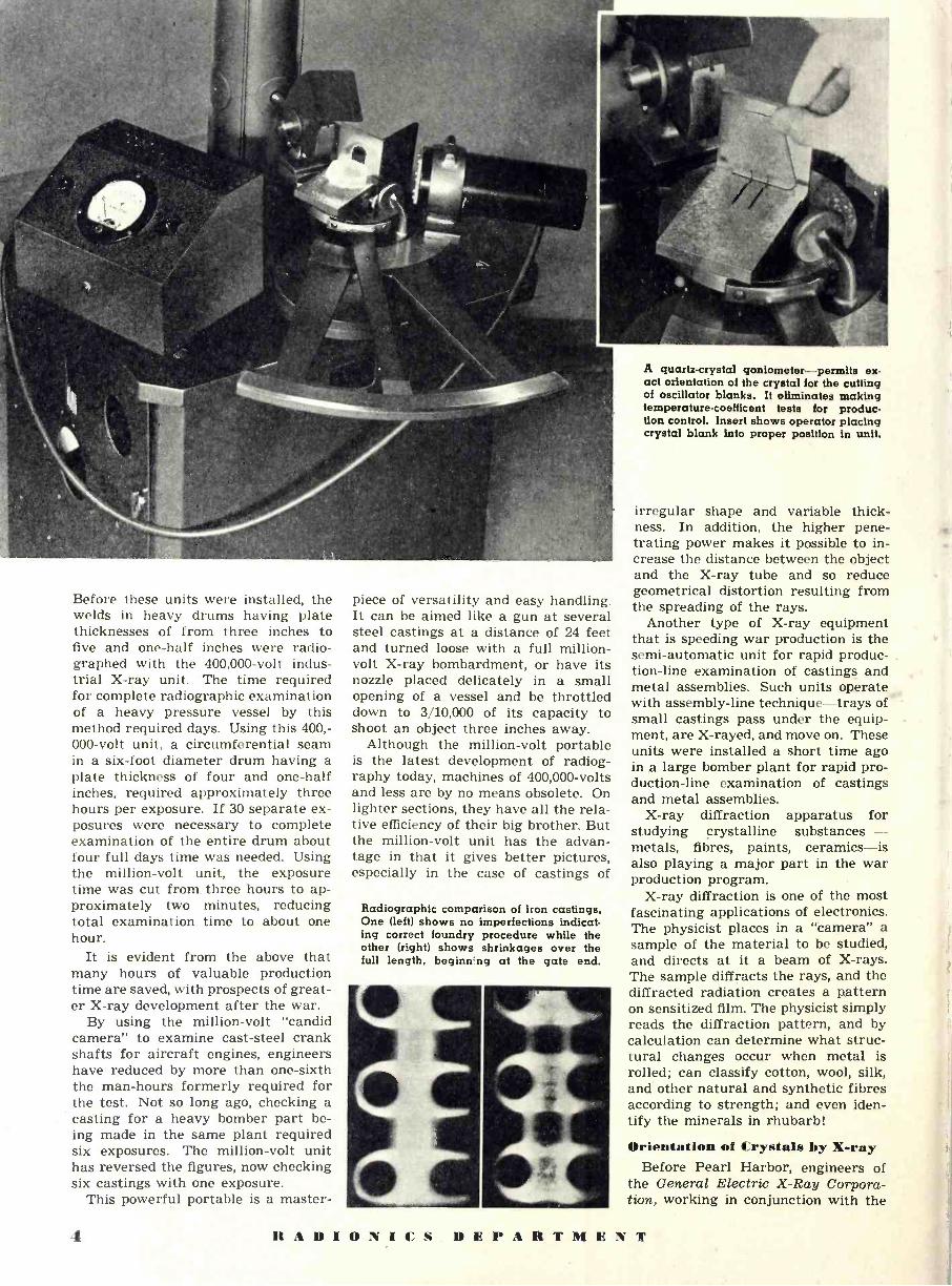
Radiographic comparison of iron castings. One (left) shows no imperfections indicat- ing correct foundry procedure while the other (right) shows shrinkages over the full length, beginn-ng at the gate end.
A quartz -crystal goniometer-permits ex- act orientation of the crystal for the cutting of oscillator blanks. It eliminates making temperature-coefficent tests for produc- tion control. Insert shows operator placing crystal blank into proper position in unit.
irregular shape and variable thick- ness. In addition, the higher pene- trating power makes it possible to in- crease the distance between the object and the X-ray tube and so reduce geometrical distortion resulting from the spreading of the rays.
Another type of X-ray equipment that is speeding war production is the semi -automatic unit for rapid produc- tion -line examination of castings and metal assemblies. Such units operate with assembly -line technique-trays of small castings pass under the equip- ment, are X-rayed, and move on. These units were installed a short time ago in a large bomber plant for rapid pro- duction -line examination of castings and metal assemblies.
X-ray diffraction apparatus for studying crystalline substances - metals, fibres, paints, ceramics-is also playing a major part in the war production program.
X-ray diffraction is one of the most fascinating applications of electronics. The physicist places in a "camera" a sample of the material to be studied, and directs at it a beam of X-rays. The sample diffracts the rays, and the diffracted radiation creates a pattern on sensitized film. The physicist simply reads the diffraction pattern, and by calculation can determine what struc- tural changes occur when metal is rolled; can classify cotton, wool, silk, and other natural and synthetic fibres according to strength; and even iden- tify the minerals in rhubarb!
Orientation of Crystals by X-ray Before Pearl Harbor, engineers of
the General Electric X -Ray Corpora- tion, working in conjunction with the
4 ICADIONICS DEPARTMENT

A million -volt industrial X-ray unit is being used here to radio- graph castings in one of the nation's largest foundries.
U. S. Army Signal Corps and quartz crystal contractors, developed a high- speed X-ray diffraction unit to assist in the accurate processing of quartz crystals for radio and other essential signaling devices.
Quartz crystals or "quartz oscillator plates" fix the frequency of trans- mitters and receivers used by the Army and Navy on land, at sea and in the air. They perform important functions in connection with artillery range -finding and submarine -detecting gear.
The piezoelectric properties of sec- tions of single crystals of quartz have been understood for some time. These properties are useful for the control of the frequency of radio transmission circuits, for chronometers, and as fil- ters in telephone communication. The study of quartz oscillators has shown that the change of the characteristic frequency of a wafer with temperature is minimum for crystals cut at one of a few critical orientations with re- spect to the crystallographic axes of quartz. The performance specifica- tions of a crystal determine the accur- acy with which it must be so oriented. This accuracy generally varies from plus or minus five minutes to plus or minus thirty minutes of arc from the ideal planes of orientation.
During peacetime, commercial transmitters minimized the impor -
Operator is preparing to radiograph several small castings on a specially -built platform with a million -volt X-ray unit.
tance of the temperature drift char- acteristics of crystals by operating them in controlled ovens. In wartime communications of the armed services, it is essential that many crystals in many sets produce the same frequency regardless of the temperature of op- eration; for example, high altitude planes must be able to communicate with their base.
The orientation requirement for crystals manufactured before the war was ordinarily met by a trial -and - error performance -selection method. Because there was no particular ur- gency in the demand for crystal oscil- lators and because there was plenty of good quartz available, a relatively in- efficient method of production could be tolerated. Two or three manufacturers used X-ray diffraction methods for control of wafer orientation, but the more common method was purely em- pirical. The preliminary orientation of the mother quartz with respect to the wafering saw was accomplished with reference to the optical and piezoelec- tric properties of the chunk. The angle of cut was approximated by measuring from a natural face of the crystal and a trial wafer was cut. Because of the difficulty of reproduceably remounting the crystal on the saw table, the saw remained idle for one to four hours while a crystal oscillator was finished from the trial wafer and the variation
of its frequency with temperature was determined. The shape of the tem- perature coefficient curve was com- pared with a series of charts prepared empirically which indicated the prob- able error of the cut for a given shaped curve. This comparison was obviously something of an art but re- sulted in a workable procedure for de- termining the error. The orientation of the quartz was then corrected and a new trial wafer was prepared., If the manufacturer had great faith in the method, he proceeded to saw up the block of quartz. Otherwise, he re- peated the test procedure to confirm the accuracy of the reorientation. Of the crystals produced, many were mediocre but a sufficient number were good to satisfy the demand. The tem- perature coefficient performance of the crystal could be adjusted somewhat by the finishing art as long as there was plenty of time and enough artists to finish the crystals.
The war placed a tremendous de- mand on the quartz crystal industry. More crystals per day were required than had been built in a year before the war, so the capacity of the indus- try had to be increased several hun- dred times. If existing production methods were to be used, the job would have been nearly impossible. The training of operators for finishing cry -
(Continued on page 36)
RADIONICS DEPARTMENT

PRiVACY SYSTEMS By JOHN KEENE MAJOR
A review of various systems that have been proposed for privacy in radiotelephony, which may in time completely supplant our present system of long-distance wire and cable communications.
R,ADIOTELEPHONY
has widely supplanted long-distance wire and cable communications,
where simplicity, reliability, and econ- omy are paramount, but with the rise of a new problem to plague engineers :
privacy. This problem has been solved with the invention of ingenious sys- tems to prevent either chance or de- liberate interception of telephone mes- sages by eavesdropping listeners.
Absolute privacy is admittedly im- possible, but practical privacy is judged by the difficulty and expense involved in any attempt by an unau- thorized listener to decipher the mes- sage, by eliminating the imposed char- acteristics from the speech received. Effective privacy, and simplicity of de- sign and construction with satisfac- tory operation are two goals largely incompatible, so that any system or combination of systems employed must necessarily be a compromise.
To secure privacy in radiotelegra- phy, high-speed transmission and sub- stitution ciphers are used, where the sequence of the symbols is altered ac- cording to a prearranged code-which itself may be changed, continuously or periodically. But radiotelephony involves the transmission of continu- ous complex signals of varying ampli- tude, frequency, and duration, which cannot be individually separated, ci- phered, and codified.
Privacy requirements are more ex- acting in radiotelephony, since the ear can accommodate to disturbances and distinguish slightest peculiarities of language. Moreover, if part of the message has been understood, the lis- tener can often intelligently guess the remainder. But at the receiver, the resulting speech after transformation must be clear and free from distor- tions other than those inherent in any radio transmission, due to faulty con- struction, improper adjustment, varia- tion of signal strength, and other propagation characteristics. It must be easily intelligible, with no new un -
It is of particular interest to note the fact that the Japanese have accumulated considerable knowledge and experience in the use of these systems. This is apparent from the amount of scientific literature available, as appearing in the references listed herein.
desirable or abnormal aberrations in- troduced to alter the speech for infre- quent users. For public service, no appreciable time delay can be toler- ated in two-way conversation; radio channels are often augmented by long land line circuits, considerably increas- ing transmission time. The maximum total transmission time is of the order of half a second to prevent "locking" of the circuit during use, since the proportion of time lost by locking in- creases very rapidly with transmission time.' The system must provide re- liability at all times with a minimum of supervision and maintenance; there must be no interference to or from other stations. In addition, ease of technical construction and synchroni- zation, reduction of expense in orig- inal outlay, and economy of operation are highly desirable.
Systems are classified into those using undetectable signals and those transmitting signals detectable on an ordinary receiver. Undetectable sig- nals generally result from a special mode of modulation. Although useful in combination with other systems, directional antennas are inadequate for satisfactory privacy - especially over long distances-due to the scat- tering of waves and the impossibility of a direct beam.2 Such transmissions can easily be intercepted on amateur receivers equipped with automatic carrier adjusters and automatic vol- ume control to mitigate rapid fading and receive satisfactory signals of very low strength.
Special methods of amplitude mod-
ulation have been suggested to gener- ate undetectable signals. The quies- cent carrier system uses voice -oper- ated thermionic switches to suppress emission during pauses of speech, but alone is practically useless, only mak- ing receiver tuning and adjusting more difficult. However, one of its foremost advantages is that of economy; since the carrier is being transmitted only when a speech current modulates it, the consumption of power is reduced to 10 or 12% compared with the or- dinary continuous carrier system used in broadcasting. Since the transmitter is not radiating during periods of re- ception, the quiescent carrier system facilitates location of the transmitter adjacent to the receiver, and enables the use of a single wave -length for ..
two-way conversation. The suppressed carrier system with
or without single side band produces an undetectable signal due to the ab- sence of the carrier wave; the only audio frequency tones delivered by the receiver are intermodulation products between various high -frequency side band components. To receive the or- iginal speech, a carrier must be sup- plied by a local oscillator, operating within 20 cycles per second of the transmitter carrier frequency. How- ever, a very stable oscillator is re- quired, and precise adjustment of the local oscillator is practically impossi- ble on short wave bands with a carrier of the order of 20 megacycles. A sin- gle side band system with suppressed carrier has been successfully demon- strated, nevertheless, with the trans- mitter providing a pilot frequency to control the receiver local oscillator. Advantages of this system include economy of power, reduction of fre- quency band on long waves and a re- duction of selective fading on short waves.
Phase and frequency modulation have been proposed to achieve privacy. Chiba published a circuit incorporat- ing an impedance bridge of three re-
Q R A D I O N I C S DEPARTMENT

sistances (two equal), and a condenser microphone, which, with a change in resistance or capacitance, would pro- duce a phase -modulated output volt- age with constant amplitude3; this cir- cuit is illustrated in Figure 1. The band width required for phase and fre- quency modulated signals is prohibi- tive for practical applications, how- ever, and as far as is known, neither mathematical reasoning nor experi- mental results have proved the ab- sence of components sufficient to pro- vide some intelligibility when the sig- nals are picked up by an ordinary re- ceiver.1
Systems transmitting detectable sig- nals change the characteristics of the audio frequency current, radio fre- quency current, or both. Probably the simplest privacy system is the multi- plex or switched channel arrange- ment, where a number of conversa- tions on an equal number of channels are switched from one channel to an- other according to a prearranged or- der. It is easily decipherable by re- cording all the channels and compar- ing the conversations to reconstruct the original transmissions. It requires a plurality of channels available with similar transmission characteristics; synchronous, instantaneous, and silent switching at each end; and a changing sequence of switching to make tapping more difficult. Though suitable for line telephony, if vacant channels are occupied with noise or conversation from records or other sources when only one or two conversations are be- ing transmitted, it is hard to apply to radiotelephony because of the difficulty in finding at least three or four radio channels with similar characteristics at all times. Synchronism can be ef- fected by a pilot channel or controlled oscillators-both of which are used in picture transmission-and the se- quence can be changed by some non - recurrent method of switching, re- peated only after long intervals.
Superimposing other sounds on speech current is impractical, because the amount of ' interfering noise to make a conversation hopelessly unin- telligible is very great. With random noise, the noise energy must at least exceed the speech energy, while with noise of one or more single frequen- cies the energy must be several thou- sand times the speech energy before serious lowering of intelligibility oc- curs. Experiments have shown that intelligibility is never less than 30% for superimposed tones from 800 to 2000 cycles, even if the added tone is 41 decibels above the speech -12,500 times speech energy., But to filter out the added noise, it must be confined to specific frequencies to suit filters, mak- ing the system impracticable for ra- diotelephony or loaded or repeatered
Fig. 1. Circuit of a privacy system using an impedance bridge consisting of 3
resistors and a condenser microphone. A change in either resistance or
capacity will produce a phase -modulated output voltage with constant amplitude.
Fig. 2. A balanced modulator with push-pull input and parallel -plate output.
It is used in a privacy system known as the frequency -inversion system.
land line circuits because of carrier power increase of 100,000 times nec- essary to handle the noise. Regard- less of the amplitude of the interfer- ing signal, certain characteristics of the original speech are retained, mak- ing the transmission easier to decode.4 The inevitable amplitude and phase modulation of the interfering signal as well as speech in transmission makes wholly satisfactory reconstitution at the receiver impossible, even with an opposing interference signal.
Best known of the privacy systems used in radiotelephony is the frequency inversion system, where a carrier fre- quency, slightly greater than the max- imum speech frequency, is modulated by a band of speech frequencies. Re- sulting output consists of the original carrier, the carrier minus the speech band (inverted lower side band), and the carrier plus the speech band (erect upper side band). For example, if the speech band comprises frequencies be- tween 500 and 2500 cycles per second and a 3000 cycles per second carrier is used, the 3000 cycle carrier is trans- mitted intact, together with the lower side band including frequencies be- tween 3000 - 500 = 2500 cycles and 3000'- 2500 = 500 cycles, i.e., the orig- inal speech band inverted; the upper
side band would include frequencies between 3000 + 500 = 3500 cycles and 3000 + 2500 = 5500 cycles. The lower side band would be inverted, with a
500 -cycle input resulting in a 2500 -
cycle output and vice versa; similarly, the upper side band would be erect. A complementary process of modula- tion with a local oscillator would be
used to receive and reinvert the sig- nal, with a receiver requiring a slight- ly wider intermediate frequency band. Since the frequencies transmitted are inverted in frequency, an unintelligi- ble gibberish results.
Various circuits may be used. Fig- ure 2 illustrates a balanced modulator with push-pull input and parallel -plate output, eliminating the carrier fre- quency.5 Matsuyaki proposed a re- sistance bridge -type modulator, using the internal resistance of two triodes as one arm (Figure 3).6 Another modulator applies the speech band in parallel with the carrier via the grid of an amplifier to the input terminals of a bridge -connected instrument type metal rectifier.? A fourth system em- ploying four vacuum tubes of similar characteristics 'is described by Niwa and Hayashi.8
Analogous to single inversion, dou- ble inversion results in components of
RADIONICS DEPARTMENT .7

Fig. 3. A resistance bridge -type modula- tor, using the internal resistance of two triodes as one arm of the bridge circuit.
Fig. 4. Amplitude transformation-where con- densers with periodically varying capacities periodically modulate speech frequencies.
Fig. 5. Circuit used to alternate the speech current-transmitting it in alternate directions for equal periods and thereby making the transmission unintelligible when interrupted
at least 1,000 times per second.
the signal being shifted by the differ- ence of two auxiliary carrier frequen- cies, by suppressing difference frequen- cies-inverted lower side band-of first inversion and the sum frequencies- erect upper side band-of the second inversion. This spread side band sys- tem, using two carriers, is not a com- plementary process, requiring two sets of equipment at transmitter and re- ceiver.
With single inversion, the resulting signal is unintelligible but can often
be deciphered to provide some degree of intelligibility, by trial tuning of a superheterodyne receiver at the outer edge of the side band, so that the local oscillator effectively provides the re - inverting carrier. The speech is ac- companied by a powerful beat between the two carriers together with noise due to the other side band and can be accommodated by the ear, though gen- erally eliminated by a suitable filter.2 To prevent interception, the inverting carrier frequency is "wobbled" up to 1000 times a second, producing a howl which the ear cannot accommodate, since the speech frequencies rush up and down the scale when the local os- cillator generates a constant fre- quency.9 Often the transmitter car- rier is likewise wobbled over a small range.
Split band systems augment the effi- ciency of privacy systems by separat- ing speech frequencies into narrow specified bands by sharp cut-off filters. So-called "scrambling" transmits these bands sometimes erect, sometimes in- verted, in any predetermined order or combination, synchronously with the receiving station. A similar method known as substitution coding uses os- cillators of different frequencies with filters for each band, to restrict the total band width transmitted; though eventually intelligible after considera- ble trial, privacy has been vastly im- proved by reducing the intervals of natural or inverted transmission to 0.05 seconds.4 Combinations of scram- bling and substitution coding with dif- ferent speech bands are almost limit- less in number.
Amplitude transformation has been proposed to achieve privacy in a method described by Tomituka and il- ustrated in Figure 4, where condens- ers with periodically varying capaci- ties periodically modulate speech fre- quencies resulting in an unintelligible amplitude modulated signal; periodi- cally varying resistances will produce the same effect.10
Fractionized speech is another pos- sibility for obtaining privacy in radio- telephony. Marro reported that the transmission of equal periods of actual speech transmission and quiescence re- sulted in definite bands of intelligible reception.11 Speech was found to be almost unintelligible when interrupted in this manner from 10 to 25 and from 210 to 270 times a second, totally in- comprehensible at 400 to 1500 inter- ruptions per second. Similarly, he found that alternating the speech cur- rent-transmitting it in alternate di- rections for equal periods-made the speech unintelligible if interrupted more than 1000 times a second.12 The circuit used to distort the phase pe- riodically is illustrated in Figure 5; since reception is complementary to
transmission, similar instruments are used at each end.
Many systems have been publicized to attain privacy, which delay trans- mission by a definite period. Though useful for one-way transmission of messages where a small lag will con- tribute no inconvenience, they are un- suitable for service connected with the public telephone network, where no further delay can be tolerated by only occasional users of the service who are unfamiliar with the characteristics of the circuit. Most of the systems in- volve recording devices, such as elec- tromagnetic recording of the speech on steel wire or tape.
The fixed delay system involves sev- eral pickups so connected as to receive the speech in an order different from that in which it was recorded, chang- ing the order of syllables of speech; synchronous switching and changing must be used at each end.13 Precau- tions must be taken, however, to in- sure that with the varying order in which the speech is picked up, no parts of the message will be missed. An electrical equivalent can be designed using delay circuits and synchronously operated switches at the terminals; such delay circuits would consist of electrical networks or high quality transmitters and receivers, connected by a suitable length of tubing contain- ing air or some other elastic fluid.
A variable delay system has also been suggested, using electromagnetic recorders and pickups which move synchronously at various speeds fur- ther to complicate deciphering; obvi- ously if the pickup moves faster than the tape and in the same direction, the order of the sounds will be reversed.14
Other systems have been proposed, which change the characteristics of the radio frequency current. Continuous or periodic variation of transmitter carrier frequency over a wide range- not to be confused with wobbling- might provide some degree of privacy, but the broad frequency band required for transmission and the resulting in- terference and disturbance to other stations make it quite impractical. Further, a wide band or automatic quick -tuning receiver might intercept and decipher the message without the advance knowledge of the tuning schedule required.
High -frequency carrier modulation is excluded because of insufficient pri- vacy and the difficulties involved in at- tempting to transmit high -frequency currents over ordinary connecting land lines with limited frequency ranges. Multiplex and split band systems suf- fer from the same difficulties charac- terizing their use in telephone line transmission and modulation.
Reviewed in this article are funda - (Continued on page 33)
8 RADIONICS DEPARTMENT

G.E. engineer shows the inside of the portable mil- lionth -of -a -second flashlight unit for use in photography.
HIGH-SPEED
PHOTOGRAPHIC
EXPOSURES
High-speed exposures show water emerging from a faucet. The photo- graph towards the right shows how the mass of water begins to break.
A newly designed small mereury lamp makes high-speed photographie exposures possible.
PHOTOGRAPHS with an expo- sure of but one millionth of a second, brief enough to stop a
rifle bullet or any fast moving object, can now be made by a new high speed electronic light equipment, developed by General Electric engineers.
This device, using a small mercury lamp no bigger than a cigarette, con- sists of a small portable box, 10 inches square and weighing less than 20 pounds. On the front is the light
. source, resembling a small auto head- light, which can be operated manually by means of a push button, or auto- matically by electrical contacts or a phototube and preamplifier. It will illuminate 20 square feet of area with sufficient intensity to photo the fastest moving objects. In fact in tests it has "stopped" a wheel revolving at 70,000 revolutions per minute.
Fastest camera shutters of the usual type, with blades moving between the lens elements, ordinarily operate at a minimum of 1/300th second. Focal plane shutters, consisting of slits in a curtain moving immediately in front of the film, cut this down to 1/1200 sec- ond. Recently published high-speed photographs of athletes, etc., have been made with a lamp giving exposures of 1/30,000 second, but 1/33 as fast as this new unit.
The new device uses standard and easily replaceable electrical parts and
a single electronic tube, with a 100 - watt Mazda mercury lamp as the light source. Such a lamp is now used as a high intensity light for illuminating airports, television and motion pic- ture studios, and for other purposes.
The ordinary 115 -volt a.c. household lighting circuit is used to operate the unit. The current is rectified by an electronic tube and then used to charge a capacitor, really an electrical stor- age tank. In three seconds enough power is accumulated to operate the lamp at full flash intensity.
At approximately 2,000 volts and 2,000 amperes, it reaches a maximum of some 4,000,000 watts. Since cur- rent flows for only about a millionth of a second the total energy in each flash is very slight. It is only enough to light a 40 -watt lamp for a tenth of a second.
Because of the pressure of war work, for which the unit was made, not much experimental work has been done on many fast-moving objects. However. work has been confined to using the device for studying high speed machin- ery, such as turbine and supercharger parts.
The small mercury lamp has a life- time of but one second but despite this brief period it will last the ordinary newspaper photographer 500 years for it is good for 1,000,000 exposures.
A one -millionth of a second exposure, of a stream of heated air being drawn through a fan revolving at 1800 r.p.m.
This small mercury lamp, about the size of a cigarette, will burn but 1 second, how- ever, can be used for 1,000,000 exposures.
It .! D I/l 1 I 1' S 11 M I' .% It TM F. 1 T I)

B
A
^ .... O 0 r. C D E F G
Fig. 1. Photographs of oscilloscope patterns, illustrating various conditions of distortion when testing an amplifier with square waves.
(A) Showing phase distortion with the low frequencies lagging the high frequencies. (B) Slight frequency distortion and phase distortion. (C) Attenuation of high frequencies with high -frequency phase delay. (D) Extreme phase and frequency distortion. Poor response. (E) Shows resultant pattern with correction cir- cuit added. (F) This figure shows the circuit as being highly underdamped. (G) Same circuit, damped
enough to stop the oscillations.
RESPONSE TESTING
WITH SQUARE WAVES By MILTON S. KI%"EIt Instructor. Illinois Institute of Technology
Square wares and their application to the testing of wide -band amplifiers. A rapid and efficient method for determining the response characteristics of ampli- fiers haring a band -width of 30 to 5.000.000 cycles.
UN the testing of audio amplifiers for frequency response all that is needed is a good audio oscillator
and an output meter. The point to point method usually employed to de- termine the response curve does not entail much work. However, when the testing of wide band amplifiers, such as those found in television work and oscilloscopes, is desired, the point to point method becomes tedious and unsatisfactory.
Another factor that is important in television work but not in audio ampli- fiers is phase distortion. The ear is not very sensitive to phase distortion un- less it is excessive. The same distor- tion in video amplifiers means the displacement of elements on the tele- vision screen with subsequent distor- tion of the image. At the low fre- quencies in television reproducing sys- tems, phase distortion affects the val- ues of lights and shadows and results in wrong shading. It is much more im- portant to minimize the phase distor- tion than the amplitude or frequency distortion. The lowest frequency usu- ally considered in these video ampli- fiers is thirty cycles. The high end is usually set at 3 to 4 megacycles but a change in present day standards might well extend this considerably.
In television and oscilloscopic work the signals involved are usually of a sharp changing form, and tend to be- come more and more like transient voltages. To amplify and reproduce these signals correctly calls for flat frequency and linear phase response over a very great range. Theoreti- cally, the best means of testing these amplifiers is to use the single pulse of voltage that rises to a finite value in- stantaneously. Such a wave would contain all frequencies from zero to infinity.
However, in practice it is more expe- dient to use a wave made up of a series of short sharp pulses. And one form of pulse which is the most practical from the standpoint of generation and use in inspection of form after it has passed through the device to be tested is the square wave.
The equation of the square wave shown in Fig. 2 may be expressed by the infinite
¡Fourier series :
e = 4E
[sin tot + lh sin 3 wt +
ir
1 sin 5 wt + 1/n sin n wt
where :
n is any odd integer e the instantaneous voltage value E the maximum voltage value.
The above series is found by inte- grating the following set of equations :
An =
Bn=
o 1 -E cos nxdx + ir f_rr
1 /E cos nxdx
o 1 -E sin nxdx + ir /-,r
1
ir fit E sin nxdx . o
where :
An and B. are the coefficients of the various terms of the Fourier series.
An inspection of this series shows that it contains an infinite number of terms, the lowest term being at the repetition frequency of the pulse. Al- though in practice the square waves obtained fall short of this ideal, yet the wave received does contain a large enough number of harmonics to be more than satisfactory in our work.
When this wave is sent through an amplifier many of the harmonics of the lowest or repetition frequency (the sin wt term) are attenuated. The re -
10 RADIONICS DEPARTMENT

sultant pattern on the screen is no longer a perfect square wave and it is through these modified patterns ap- pearing on the screen that we can tell much about the frequency and phase response of the amplifier. In the next section we shall attack this problem mathematically and show how the re- sults thus obtained apply to photo- graphs of patterns actually obtained in practice.
It is well to mention at this point that amplitudes of square waves are seldom, if ever, measured. The wave shapes seen on an oscilloscope are gen- erally independent of amplitude as long as there is no overloading. Thus the needed apparatus for this type of testing include only a square -wave generator and a good oscilloscope. Here is a decided advantage over the sine wave point to point method.
Theory
Inspection of the equation of a square wave brings to light several things;
1. The wave consists only of odd harmonics.
2. That the lowest frequency can be put at any figure within the range of the generator, thus enabling us to test the response of a circuit independently at high and low frequencies.
3. And lastly, that in order for no phase distortion to take place, phase shift of each harmonic should be pro- portional to frequency.
It should be noted here that we may have a phase shift without phase dis- tortion. As long as each element in the wave is shifted proportionally to the frequency, there is no phase dis- tortion. We can prove this easily enough. Suppose the incoming wave :
e1nput = A sin (wt + 0,) + A3 sin (3 wt + 0-3) -I- A5 sin (5 wt + 05) #- An sin (n wt + 0n)
where : n is any odd integer An is the amplitude of the nth har-
monic impressed on the amplifier. As- suming the gain to be unity and that the phase shift is proportional to fre- quency, then the output wave can be expressed as:
eoutpuc = Al sin (wt + 01 + el) + A3
sin (3 wt + 08 + 3e1) + A5 sin (5 wt
+ 05 + 5e1) + An sin (n wt
+On+n01) Although a phase shift has taken
place, there is no phase distortion as can be seen by choosing another time axis t', defined as :
wt+0=cot' Substituting this equation, in the
former one, would give :
eoutput = Al sin (wt' + 01) + A3 sin (3 we + 03) + A5 sin (5 we + f . )
-{- An sin (n wt' + 0n)
which is of the same form as our in- put wave equation.
The fact that we have only odd har- monics of the fundamental in the wave indicates that the amplifier is not be- ing tested at all frequencies but only at a set of discrete values. While this may appear to be a disadvantage, prac- tically it isn't because amplifiers tend to vary without any sudden sharp dis- continuities in their response curves. Another way to get around this dif- ficulty is to vary the fundamental fre- quency and thus any sudden changes will usually be brought to light.
We can learn a lot by plotting the above equation using a different num- ber of harmonics each time. This has been done and the results will be found in Fig. 5, where it can be seen that unless a substantial number of har- monic components are included, the resultant wave form only approxi- mates a square wave. Here we are only dealing with amplitude distortion since it has been assumed in the proc- ess that all waves come through with- out any phase distortion. It will be seen that with frequency distortion all four corners of the square wave are affected the same way. This is a characteristic of the sine terms that compose the equation. Getting any of the patterns mentioned from an amplifier shows high attenuation at the higher frequencies. The smoother the curve, the less the attenuation.
Now suppose we plot the series us- ing about 20 harmonic terms and in- troduce phase distortion in the higher harmonic terms. Our series will be:
e [sin 4E (w + te1) -I- y3
T
(3 wt + 03) -!- sin (5 wt +
+ 1/n
sin
05)
sin (n wt + 071)1
NIPZ .e. üt7sctaitt. . ..
'?is:ar. _leim:I'ii:i:: !:°!''3'Ii i .ydr'rifä:::?::ta
Fig. 2. Square -wave input signal. Fig. 3. Output wave with frequency
attenuation and phase distortion. Fig. 4. Output wave -form obtained when
amplifier is insufficiently damped.
where by the vation
On is a phase shift introduced particular system under obser- and it is not proportional to
frequency. In Fig. 7 we see a wave that has both high attenuation, and also quite a bit of phase distortion. It is to be noted in general that when phase distortion is introduced into the square wave, then the four corners of the pulse are not equally affected. - Each half -wave pattern is no longer symmetrical about the y axis. Fre- quency distortion alone preserves this symmetry, so this is one method of
Fig. 5. Resultant waves obtained when using various numbers of odd harmonics. (A) Fundamental only. (B) First 7 odd harmonics. (C) 15 harmonics. (D) 25 harmonics.
::'iiHiiHi MM3m!'llllliiinlngnllNIll!!1!IlIINnIl11 MINIM 'I:I;':.I',;I;1iifrMMIT#1?iIIIIINIIIIIFIiiiSI!#It
ii äHI IäilM IIG!iIINII}llMü IIIIIIIIIIIIiIlillllil11
1 IIIII HäHIE IMIiHIIMHI10 !'i.=.Illi!'IIIIIIMIIç13M
!MIES?äHäilllliilliiii iliiililiiilillallil.ill
u RE HM i111HIlIHIHIÌi1 iII3Ii'iHHHIli:liliH ii i: IIIlliiil':il liliiillälllla!I =li'IliHlliiiiilllll :... ::::":
ä a:iii 3'i i'i 3!!=iisi ii'ai i, . ::i lI.Hlill ;i : 3:..i:li I:i3.IlIIl;1i:;.:3:i..il= : i..l.ì Milli ä11:iIMiliM!rc- a!:!
:ai: al
iiii: lllllllll, lilli ,
H s sisii: rc ss 9!!3! __!! 3== 33 !!!ii éii;iiiililli.NII`iai!!i!ll:ii::nii3lli:i:i!!lll
iliAiluu!iiliiiiiiulalliii....,...ilinii;pii3i;ii13i33iiili3í.s;#II!m
litirIilIIH. IIIlIHiiliilIlliNliliilll:illlillllllilii!llliil ill ilüilillgliiilllill!!!'!#iN!!i!i#'#iii!!!llllliil;iil . a ..
1 1 , .. : >, a::::rc: ü u. ):ilii I iiliililll ..IIIIiÍIIÄélisii .i1133lilliill.3.a...:
NMI BIZllfiiläHHlfllH :illläällHllHllHllliliiliillllla!! lääiiiilill.HHäii!!HH Ilflllllllll!llfll If.ifllilllllllliiiiii3 'lillálllll ilIHHIHIIiI# Iliilllilliii IiHIIlHilil'Ji=.i;l äfll?Iäällfillifi'lläälällillllil'flllllllflllEällä ällällällläälliiill lläälllifillflilHlü l!l!:liiiilarlHi IlIHHäiälH!'=.I ii -''!!!!i#llllHil#lli
illlällllllllfflll.illlllilii!!lillililliiii iiällllllllllllllllfllllHliHlllllillll ilIIIS I Hlllllillllälllllilllliiiiil
1rci::' lllfllllilllilälllllllällllllHä
,9:1i.` : i`Il=HialIIHiIilHllilH >-ilil _~ : s .i...; i:`.F.: :: :. ill! iCè.Ili:Eiii93f3ilu
!liälllilïEfäIlHHälllä I!'iill;alH"!I! HHIIIHH
HIiHlHii 11111111il.I 51 -5-t is r: e:u igg,, ,,sgq a yg,,77 , 3:3iiiiiflEi3llüx! iäilliliilli 7li:is3ällif
IIIiPIIIlHIIi HHIIHHHH puma s:il33=iiiii c =i-ilii!!!i
HäiälHl"E:.i : : i;1 r.pp 7: H:11rc?33es-l::j 1. i as ii = lt l: yY3;7:a:: fiaafiattislilll!!#lM:::i:
= u3 !fg3afff !!!!!!!. i;;si3Eo:ii:IiiIIIIH 3 liilsa:Itiäa!!-:li?IHI ::::s^
issu: :i :sn iillll!l:II=II1S.iIIII
::!?illllii3.íiiil:3?i ireqili;:g;i
i a i3! li: H H H H ! m..3 ii. x n i . !l..r::r.::::!. :x i Ei3lsi_ _
9HoHm3 lliiiui;tiwa Allegan u
i i i
Ei g
=i l E i . :
iWARM! Hiá' iiúi3'si' .3i a lïiila Ii i3 !¡.' ir::l:l .:1.::1::i:llllW! 3iäl !llHllii
HIIIIIIIII
ANON!
tit
i3!
D) "
!
:S::i==!ºEH3isillllHlll ... -:a::._ `l S1!f 1.1-1l:11 !!!3 i2311111- 3iB?1 . :-HN,yç!SS]!

Fig. 6. Coupling circuits of resistance -coupled amplifier. (A) Equivalent circuit at the low -frequency end. (B) Same circuit with low -frequency compensation. (C) Equivalent circuit at the high -frequency end. (D) With high -frequency compensation.
recognizing phase distortion, even if high frequency attenuation is present.
One more idea should be touched on briefly before some of the practical testing with square waves are dis- cussed, namely, oscillations. As is well known there are some compon- ents in an amplifier that will oscillate strongly if their resonant frequency is reached. Should the circuit be under - damped, then a series of oscillations will take place lasting for a short while and giving excess gain. Fig. 4
shows what the oscilloscope pattern looks like when a circuit is under - damped and the resonant frequency is reached. Loading the circuit will in general minimize the gain that is had and tend to flatten out the response curve. Overloading will result in very low gain.
With the above analysis in mind we can next turn to the patterns actually received in practice. It will be found 'that many of the patterns in Figs. 2-5 will reappear again.
Praetical Examples
As previously mentioned, all that is necessary in the way of equipment is a square -wave generator and an oscil- loscope. The first test to be run off should be on the oscilloscope itself in order to ascertain whether the ampli- fiers in the scope will pass all the fre- quencies needed. One of the better types of oscilloscopes on the market that was used in this test, was found to display the pattern shown in Fig. 1A for the low frequency end when the repetition frequency was near 50 cycles. As the repetition frequency was raised, the wave assumed more and more of a square shape, until at 150 cycles the wave showed good re- sponse with very little distortion. In order to interpret the low frequency pattern, we must look at the equivalent circuit of a resistance coupled ampli- fier. This is shown in Fig. 6A. The
gain of the stage with this circuit at the low frequency end is given by :
AL=gmR°
where :
1
Nj1+X`2 R,2
g,,, = mutual conductance of tube rp RL Rg
R°_ rp RL -f- rp Rg + RL Rg
Rt_Rg+ RLrp
Xe = reactance of coupling condenser
The phase shift due to this coupling network is:
= tan -1 Rg°
= tan -1 wC R
° g
= tan -1
where :
1
wT
T = time constant of Ce Rg
The greater C° Rg is, the greater the time constant T will be and the lower the frequency response curve will go. However, it has been found by Keall1 that instability and relaxation oscilla- tions take place if T is greater than .01 seconds. Single stages may not be troubled by this large time constant but multiple stages will be aggravated to a point of instability.
Thus the decrease in the flat-topped portion of the square wave is an in- dication that the time constant is not large enough. Usually a change in height of the wave at each end up to 7 percent is tolerable in television work, although there are times when only a few percent will be noticeable. The percentage change in the height of the square wave may be had directly from the oscilloscope by measuring the height at each end, taking their differ-
ence and then dividing by the larger height. Increasing the size of Rg to improve the response may be injurious to the next tube if it contains even a small amount of gas, while as Cc is increased its leakage current rating will become more and more trouble- some. With these limitations in mind, designers had to look elsewhere in the circuit for low frequency correction.
One solution most widely used is shown in Fig. 6B. Here another resis- tor Rf and condenser Ct have been added. At the high frequencies Cf effectively short-circuits Rt so the added circuit has no effect on the up- per response. At the lower frequen- cies the reactance of Ct increases caus- ing amplification to increase. The most important effect, however, is that the phase shift of this network is in a direction opposite to the phase shift of the coupling network, thus correct- ing for some of the overall phase dis- placement. Decoupling is also accom- plished at the same time, further add- ing to the stability of the amplifier. Since this is not an article on wide - band amplifier design, it has therefore only covered as much of the subject as is necessary to help understand the patterns received. For those who de- sire a more complete analysis there are a few references given at the end of this article -2, 3, 4. With the cor- rection circuit inserted into the net- work, a flat-topped wave can be had down to about 40 or 50 cycles.
Returning now to the amplifiers in the oscilloscope, we raie the frequency of the square -wave generator until the higher frequencies are reached. Figs. 1B, 1C, 1D show three degrees of fre- quency and phase distortion, increas- ing as the frequency is raised. We can tell that there is phase distor- tion because each half of the wave is not symmetrical with respect to the y axis. This fact has been mentioned previously in the theory portion. As is well known, the falling off of the response curve is due to the shunting effect of the stray wiring plus the vari- ous interelectrode capacitances. One means of counteracting this is to lower the plate load resistance (RL). How- ever, this will at the same time de- crease the available gain of the stage. Usually a compromise is reached, gov- erned by the equation :
gm Ro 1
1-}- R°z XZCT
where :
XCT = reactance of total shunting capacitance.
R° = equivalent resistance of rp, R,, and Rg in parallel. (See Fig. 6C.)
(Continued on page 28)
12 BAD IONICS DEPARTMENT

The Nature of
COSMIC -RAY PARTICLES h. DR. MARCEL SCHEIN Research Associate, University of Chicago
An analysis of cosmic -ray phenomena --a new field for future fundamental research made possible through the discovery of new particles in nature and the establishment of new physical laws in the region of higher energies.
HE great significance of cosmic - ray research is demonstrated by the discovery of new fundamental
particles in nature, and by the estab- lishment of new physical laws in the domain of very high energies. These achievements have contributed greatly to the progress of physics in general, and have opened up new promising fields for future fundamental research. Many of these new discoveries are ex- plained by theories based on well- known ideas of the electromagnetic field. However, more recently a num- ber of very remarkable new phenom- ena were found which lie beyond the horizon of present-day theories. Prob- ably a new development of our basic ideas in physics is necessary before a satisfactory explanation of these phe- nomena can be expected. We believe that at present such a development depends greatly upon the success of experimental research in the field of cosmic -radiation. This seems particu- larly true of investigations of a recent- ly discovered particle in physics, the so-called mesotron. So far the meso- tron demonstrates a number of very unusual properties, particularly in its interaction with atomic nuclei. This might even lead to practical applica- tions some time in the future. Indeed we have to remember that after the discovery of the electron, a consider- able time passed before its usefulness to industrial research was demon- strated.
The analysis of cosmic -ray phe- nomena at sea level shows that the main body of this radiation consists of mesotrons. In addition, a variety of other particles are also found to be present. It seems of general interest here to describe the most effective ex- perimental methods which have been developed at the present time to study the properties of cosmic -ray particles.
Passing through a gas each indi- vidual cosmic ray produces a number of secondary effects which can easily be detected by electrical methods. As a result, we are able to study the be-
havior of single cosmic -ray particles. This represents a distinct advantage over physics of low energies wherein the average behavior of a great many atoms or electrons can be investigated.
Fig. 1. A diagram of two 3 -fold coincidence circuits, using 4 Geiger -Mueller tubes.
N
-1.5 2
3
4
N
-1.5
IN5G
IN5G
IN5G
IN5G
+155 +180
I MEG.
o o ó
o o o
-45 +112.5 + 80
W
-45
1 MEG
+1125
o o o
+180
-1.5 +155 +180 ALL FILAMENTS = 1.5 VOLTS

Fig. 2. Cosmic -ray detection equipment, with outer cellophane wrapping re- moved, used for stratosphere flights.
To study high energy phenomena in an efficient way it is generally required to build machines in which particles of known energies can be generated. Great efforts have been concentrated on the solution of this problem. Physi- cists succeeded in building large ma- chines like cyclotrons (Lawrence) and more recently betatrons (Kerst) which generate particles of several (100) mil- lion electron -volt energy. However, there exist a number of fundamental processes in nature which take place only at energies much higher than the above given figure. Most striking is the discovery that the already men- tioned new particle, the mesotron, only occurs in such phenomena in which particle energies higher than 100 mil- lion electron -volts are involved. This apparently means that in such proc- esses mesotrons can be created by collisions between fundamental par- ticles. It was recently found that such a creation of mesotrons actually takes place in the cosmic -radiation.
It is of considerable interest that na- ture supplies us with a permanent
Fig. 3. A high -altitude barograph mounted on top of the recording mechanism.
source of high-energy particles which enter from outer space into the earth's atmosphere. In this so-called cosmic - radiation we are dealing with parti- cles which have energies much higher than anything we know from labora- tory experiments. More than 10 years of intensive research in which some of the leading physicists participated were necessary to establish some of the fundamental properties of the primary cosmic -radiation. As a result of these investigations we now believe that the large majority of the pri- maries are electrically charged par- ticles. The lowest energy measured for primaries is approximately one billion electron -volts (109 ev).1 The highest en- ergies found in cosmic -radiation are as high as ten million times billion elec- tron -volts (1016 ev) . In between there exists a whole energy spectrum of par- ticles. However, the number of in- coming rays rapidly decreases as we pass from lower to higher energies.
The origin of cosmic radiation is still a mystery. In the interior of a star no mechanism can be found which would lead to the emission of particles with energies as high as 1016 ev. Even a complete transformation of the mass of the heaviest element (uranium) into kinetic energy of electrons would not yield more energy than 2 X 10¹¹
ev. So it seems very probable that cosmic rays originate in interstellar space. Astronomers recently found that the space between the stars con- tains small concentrations of hydro- gen nuclei (protons), electrons, and negatively charged dust particles. It is, however, hard to imagine the na- ture of the mechanism by which some of these particles obviously attain a kinetic energy as high as that observed for cosmic rays.
At the latitude of Chicago (51° North geo-magnetic latitude) the primary cosmic -radiation enters from all direc- tions isotropically. The total amount of energy falling on each cm2 per second is found to be 3.5 X 10⁻³ ergs. This energy flux is approximately the same as the flux of the total star- light (sun excluded) which amounts to 3.02 X 10⁻³ ergs per cm2 per second. It is a rather interesting fact that cosmic -radiation emitted from inter- stellar space carries about the same energy as light emitted from all stars.
In a series of balloon experiments carried out for several years in dif- ferent parts of the world, Bowen, Mil- likan and Neher determined the total incoming energy of cosmic radiation as a function of geomagnetic latitude. The results of these investigations
1 A possible explanation of the fact that primaries with energies smaller than 109 ev cannot reach the earth, lies im the bending of the cosmic -ray particles in the magnetic field of the sun.
show that the energy carried by the primaries into the earth's atmosphere strongly depends on latitude, the ef- fects being the largest between the equator and a latitude of about 50° (north or south). For instance, the primary energy flux is 2% times smaller at the equator than at the latitude of Chicago. This dependence of cosmic -ray intensity on latitude can be explained by the influence of the earth's magnetic field on the motion of the cosmic -ray particles in space. Indeed, it is well known that charged particles moving through space repre- sent an electric current which is de- flected by a magnetic field. The theo- retical calculations of this effect, car- ried out by Stormer, Lemaitre, Val- larta and others, lead to the result that a minimum particle energy is re- quired to reach the earth at a given latitude. For instance, an electron must have a minimum energy of 2% billion electron volts to reach the earth at the latitude of Chicago and an energy of 15 billion electron volts to reach the equator. Thus the latitude effect as measured by Bowen, Millikan and Neher means that more than 60% of the total cosmic -radiation has its energy between 2% and 15 billion electron volts.
We mentioned above that at Chicago the cosmic rays enter from all direc- tions isotropically. This is not the case any more if we move closer to the equator. It was found that at latitudes near the equator the major- ity of the cosmic rays enter from a westerly direction. The theory of the magnetic bending predicts such an ef- fect provided the cosmic -ray particles carry predominantly positive charges. For equal numbers of positives and negatives no directional asymmetry could occur. Hence the experiments on east -west asymmetry represent direct 'evidence that a large fraction of the cosmic -ray particles are posi- tively charged.
What is the nature of the primary cosmic -radiation ? It is a very diffi-
cult task to give a definite answer to this question. The reason is : The pri- maries entering the earth are very quickly absorbed in the atmosphere; thus only a negligibly small fraction of these rays can reach the surface of the ground. This means that all investigations of the primaries have to be carried out high in the atmos- phere, and we have to build a small self-supporting cosmic -ray laboratory which has to be carried by balloons to the higher altitude.
Two possibilities have been sug- gested regarding the nature of the primary cosmic -radiation. Millikan and his collaborators seem to believe that the primaries consist of electrons.

During the last 3 years, in collabora- tion with Drs. Jesse, Wollan and Iona, the writer carried out a series of ex- periments in the stratosphere which possibly threw direct light on the na- ture of the primary radiation. In these experiments, the penetration and shower production of the primaries were measured in different thicknesses of lead, and, as a result, we came to the conclusion that the main body of the primary cosmic -radiation does not consist of electrons. Most of our ex- periments support the idea that the primaries are protons. A similar hypo- thesis was put forward by W. F. G. Swann of the Franklin Institute.
The problem, whether the primaries are electrons or protons, is of consider- able interest. In case they were elec- trons, their main interaction with the matter in the atmosphere would con- sist in producing so-called showers of electrons and photons. Since the shower -production is an electromag- netic process, it can be described by the well-known laws of the electro- magnetic field. This is entirely dif- ferent in the case of protons, which do not produce showers in the air. Their most important interaction con- sists of the creation of mesotrons which takes place in nuclear collisions and cannot be described by any known theory in physics. This action is unique, and is responsible for the pres- ence of mesotrons on the earth.
Experimental Methods (a) Counter Tubes and Coincidence
Circuits :
The simplest instrument, for regis- tering the presence of single high en- ergy particles is the so-called Geiger - Mueller counter. It consists of a cylin- drical metal tube filled with a gas at a few ems. of Hg pressure. In the center of the tube a wire of a few thousandths of an inch thickness is mounted. This central wire is elec- trically insulated from the cylinder. Between the cylinder and the central wire a potential difference of several hundred volts is applied.2 The exact value of this voltage difference de- pends on the gas pressure and the di- ameter of the cylinder.
The action of the counter can be described as follows A high energy particle entering the counter initiates an electrical discharge in the gas. The current flowing through the tube lasts only for a limited time and ceases to exist very shortly (in about 1/10,000 of a second) after the passage of the par- ticle. This electric pulse of very short duration can easily be amplified by a system of radio tubes. The mechanism of the counter discharge is a compli-
2 The cylinder of a counter tube has to be made negative with respect to the central wire.
Fig. 4. A flight of 28 balloons attached to an apparatus weighing 45 pounds being released from Stagg Field on the University of Chicago campus, for cosmic -ray observations.
cated phenomenon and has not yet been analysed completely. However, some of the important factors which seem to determine the action of a counter have been successfully inves- tigated.
The primary effect of the impinging particle is the liberation of an electron from a molecule of the gas. This proc- ess is called the primary ionization. The electron liberated in the gas is accelerated toward the positively charged central wire. Close to the wire the electric field is very strong and the electron attains a kinetic energy sufficiently high to ionize another molecule. The electron produced in this secondary ionization process will also move toward the central wire and it will liberate another electron in the gas. This multiplication of electrons goes further on, and, as a result, an electronic current of about 10-10 am- peres develops in the tube. The time required for this multiplication pro- cess is extremely short, certainly not more than 1/10 of a microsecond. The initial electronic current is localized in
the neighborhood of the central wire covering all but a very small part of its surface.
It is of great importance for the ac- tion of a good counter that this local- ized current can quickly spread over the whole surface of the central wire. This spreading effect is due to the ac- tion of ultraviolet light (photons of short -wavelength) which is produced by the electrons moving toward the central wire. It was found that the ultraviolet light in a counter has a sufficiently short -wavelength to liber- ate electrons from the molecules of the gas and also from the walls of the cylinder. Since the photons can travel all over the surface of the counter this action is not localized in the tube. Each electron liberated by ultraviolet light moves toward the central wire and initiates its own avalanche of electrons. The electronic current spreads over the whole surface of the wire. As a result, in a good counter the current can reach a value of about one microampere. It is interesting to note that the addition of organic vapor
Fig. 5. A diagram of the time versus altitude of a cosmic -ray flight in September, 1942. rrr 24 -
20 'A
;22316
9 Y 12 z
8
4
ZZZZZZZZZZ 2,11110141
rl 4 0
.3
M 0 2 3 7 9 10
TIME IN HOURS
14

Fig. 6. General arrangement of a cloud chamber in the field of a permanent magnet.
to the gas seems very essential for the efficient spreading of the electronic current over the whole surface of the central electrode. Since the process of spreading is due to photons, the total electronic discharge develops in a very short time after the passage of the initial particle through the counter. This time interval can be measured to less than one microsecond.
To each electron liberated from a molecule of the gas there corresponds a remaining positive gas ion produced in the same process of ionization. The positive ions have a much larger mass than electrons and, as a result, their mobility in the gas is considerably smaller. During the time interval in which the electronic currents develop (less than one microsecond) in the counter, the positive ions are not able to move very far and stay in the neigh- borhood of the wire. They form a sheath of positive space charge around the central electrode. The presence of the positive ions reduces the electric field around the wire. The reduction of the field is so great that electrons
Fig. 7. Photograph of an electron and mesotron, obtained from a cloud chamber.
entering this zone are not able to pro- duce any further ionization in the gas. Thus the electronic current toward the central wire is interrupted and the discharge through the counter is quenched.
To make the counter susceptible for the next high energy particle which happens to enter the tube, it is neces- sary to remove the electrons from the central wire to ground potential. This is generally done by grounding the wire through a large resistance. Choos- ing the value of this resistance around .1 of a megohm the flow of electrons to ground will take place in a very short time (about one microsecond) provided the capacity of the wire sys- tem is not larger than 10 ems. At the same time the positive ions, located in the neighborhood of the central elec- trode, move toward the negatively charged cylinder and become neutral- ized there. Their speed, however, is much smaller than that of the elec- trons. In a counter tube of 1 inch di- ameter it takes about 100 microseconds for positive ions to reach the cylinder. Any particle which enters the counter within this time interval cannot be registered. Hence, this represents the dead time of a counter.
The short description of the action of a Geiger -Mueller counter given here is very tentative and many de- tails regarding the operation of dif- ferent types of counter tubes were in- tentionally omitted.
A single counter tube registers cos- mic -ray particles entering from all directions. For different purposes it is important to study cosmic rays coming from a given direction. To solve this problem the technique of the so-called coincidence counter was developed by which the simultaneous passage of an individual cosmic -ray particle through several counter tubes can be regis- tered. Within the last few years a number of different electrical circuits were developed which are now used for registration of counter coincidences. The first coincidence circuit was pro- posed by Bothe in 1928. In 1930 Rossi suggested a new circuit which since that time has been used frequently in cosmic -ray research.
In Figure 1 the diagram of two 3 -fold coincidence circuits is given.3 Circuits of this kind were used by the Chicago group in balloon experiments in the stratosphere. The electric power was supplied by little dry batteries.
1, 2, 3 and 4 in the diagram repre- sent 4 Geiger -Mueller counters (filled with argon -alcohol). The counters can be arranged in a vertical row. Such
8In the diagram the voltages are given in volts, capacities in microfarads and resist- ances im ohms.
For flashing the neon lamp, a minimum voltage of 80 to 100 volts is required.
an arrangement is called a counter telescope. Counters 1, 2 and 3 are connected to one 3 -fold coincidence cir- cuit, and 2, 3 and 4 to a second 3 -fold circuit. Every one of the 4 counter tubes is bombarded by cosmic -ray par- ticles from all directions.
The central wire in each of the counters 1 and 4 is connected to the grid of the corresponding IN5G tubes. Counters 2 and 3 are common to both 3 -fold coincidence sets, thus the cen- tral electrode in each is connected to two different vacuum tubes. The con- ditions in the IN5G tubes are so ad- justed that a plate current of nearly two milliamperes flows through the resistor of 0.1 megohms. As a result the voltage drop across this resistor is approximately equal to the total plate voltage (180 volts) and the potential across the vacuum tubes amounts to a few volts at most. If then one of the counter tubes is traversed by a cosmic - ray particle, a pulse of negative elec- tricity is generated on the central elec- trode and the grid of the IN5G tube will get more negative. The size of this negative pulse is sufficient (voltage change of the grid more than 5 volts) to interrupt the current flow through the tube. Since, however, the voltage across the vacuum tubes is very small in comparison to that across the 0.1 megohm resistor the interruption of the current in one of the IN5G tubes will change by very little the potential drop across this resistor. This change in potential amounts to a few volts and is too small to flash the neon lamp 4 in the grid circuit of the IA5G tube.
It is obvious from the diagram that a similar thing occurs if any two of the the counters are actuated at the same time (2 -fold coincidence). However, if 3 counters of the same coincidence set are discharged simultaneously then the plate currents in all corresponding IN5G tubes are interrupted and the potential across the plate resistor changes by nearly 180 volts. Naturally, a voltage pulse of this size is sufficient to actuate the neon 'flasher. By that the grid of the IA5G tube gets positive and the tube passes from the non -con- ducting into the conducting state. Finally, the 3 -fold coincidence ,is re- corded by a flash of the second neon lamp which is placed in the plate cir- cuit of the IA5G tube. This flash is of very short duration (less than 1/10,- 000 of a second) and has to be made longer in order to record it on a pho- tographic film. The pulse in the plate circuit of the IA5G tube can be length- ened by a feedback to the screen grid of the IN5G tube through a large con- denser (0.5 pfd.). Such a multivibrator circuit gives square pulses of long duration (1/10 of a second). The flash

in the neon lamp is then much longer and can easily be photographed. It is clear that by adding more vacuum tubes the same kind of circuit can be used for registering coincidences be- tween any given number of counter tubes.
For certain investigations it is of definite advantage to use the combina- tion of 2 or more coincidence arrange- ments. In Fig. 1 two 3 -fold units are shown. More recently we were using in our stratosphere experiments as many as 6 different coincidence sets (4 and 5 -fold units).
This makes it possible to carry out a number of different experiments at the same time and as a result in one single flight, data can be obtained equivalent to the results of several flights. The photograph in Figure 2 shows one of the balloon outfits used by the writer and *J. Tabin in last year's stratosphere experiments. ' The counter tubes are visible in the middle upper part of the apparatus. On each side of the counters 3 coincidence units are mounted. ' The metal box in the middle contains the photographic re- cording equipment. Close to it the high voltage battery (1100 volts) can be seen. The various batteries supplying the voltages for the filaments, screens and plates of the vacuum tubes are mounted below the recorder. During the flight the whole apparatus was covered with cellophane. This was done for the following purpose : The sun- light trapped inside the cellophane kept the temperature in the interior around + 60° F. in spite of the fact that the outside temperature in the stratosphere was as low as 50° below zero. To get a better regulation of the temperature inside the cellophane box part of its surface was covered with a reflecting material (silver paper).
The details of the recording mechan- ism are shown in Figure 3. Recorders of this kind were constructed by W. P. Jesse and have been used previously by the Chicago group. The upper part of the recorder shows the high altitude barograph.5
The barometric pressure is continu- ously recorded on a rotating drum driven by the clock mechanism visible in the picture. The large Dow (Mg -Al alloy) metal drum (shown in the mid- dle of the photograph) is driven by the same clock. At the end of each turn, which takes one hour at a time, the drum moves by 1mm downward on the screw. A photographic film of high sensitivity is mounted on this drum.
On the film the flashes of 6 different neon lamps are photographed. These lamps are mounted in the endpieces of two telescope tubes, each tube contain- ing 3 lamps. A fine slit is placed in front of the neon lights. The focus -
Fig. 8. General installation of a large ionization chamber outfit as used by R. Lapp. This unit, called a Carnegie meter, was constructed by Compton, Wollen and Bennett.
sing of the lights is done by microscope objectives, thus the flashes occur as very fine spots on the film. By using this recorder a continuous registration of cosmic -ray coincidences during a time interval of 12 hours can be ob- tained. This is generally sufficient.
In Figure 4 one can see the launching of a larger balloon flight from Stagg Field on the campus of the University of Chicago. In this flight 28 balloons attached to an apparatus of 45 lbs. were released by a special system of ropes. The ropes were only used un- der severe weather conditions.°
After the balloons left the ground they rose with a nearly constant speed of 600 to 800 feet per minute.? At the highest altitude several balloons burst and the rest carried the apparatus to the ground. However, on several occa- sions the balloons stayed in the strato- sphere for an unusually long time. This happens apparently if the num- ber of balloons bursting in the high altitude is relatively small. As a re- sult the total lift which is left over just about counterbalances gravity and the outfit reaches an equilibrium state in the stratosphere.° The bal- loons are floating for several hours in the high altitude. Then the cold air at nightfall causes their descent to the ground.
In the diagram of Figure 5 a time versus altitude curve is given for the flight on September 1, 1942. One can see from the curve that the balloons
e These instruments have been frequently described in the literature, and it is assumed here that the reader is familiar with the principles of their construction:
e The flight was launched in the morning of January 5 (1948) in very cold weather.
T For a given apparatus this speed depends on the total lift.
s For a better understanding of this effect one has to take into account the strong heat- ing of the balloons by. direct sunlight in the stratosphere which is also counteracting gravity.
stayed for several hours in altitudes between 24 and 25 kms.
The distances in which the balloons were found vary somewhat with the season. In the latter part of the au- tumn and in winter they travel with a horizontal speed of 150-200 m.p.h. in the stratosphere and are usually found 400-500 miles from Chicago. In the summer and early in the fall they may be recovered much closer (100-200 miles from Chicago). Naturally for flights in which the balloons reach an equilibrium state in the stratosphere these distances can be very large. For instance in the last flight on July 31 (1943), mid -summer, the apparatus landed in Virginia, 550 miles from Chi- cago.
For cosmic -ray investigations at sea level and at mountain altitudes, coun- ter outfits had been constructed . in which a very large number of counters (more than 100) and coincidence cir- cuits were used. Outfits of this kind were built by Swann and his collabora- tors at the Bartol Research Founda- tion, V. H. Regener, at the University of Chicago, and L. Janossy in Man- chester (England). In these outfits the counters cover a large area sensitive to cosmic rays. One is enabled then to study the occurrence of very rare phe- nomena in cosmic radiation.
(b) Cloud Chambers: Frequently in cosmic -ray experi-
ments we are not dealing with one in- dividual particle but with a collective phenomenon like a whole shower of particles. The Geiger -Mueller counter does not discriminate between such events. Namely, one obtains in the counter an identical discharge irres- pective of whether a single particle or a shower of particles pass through it. A further disadvantage in using count- ers lies in the fact that a direct meas-
(Continued- on page 27)
HAD IONICS DEPARTMENT 17_
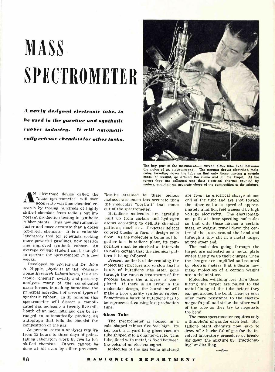
MASS
SPECTROMETER
A newly designed e1eeironie tube, to
be used in the gasoline and sgnihNtie rubber industry. /t trill aulomati- eallg release ehemists tor other /asks.
N electronic device called the "mass spectrometer" will soon accelerate wartime chemical re-
search by freeing hundreds of highly skilled chemists from tedious but im- portant production testing in synthetic rubber plants. This new instrument is faster and more accurate than a dozen top-notch chemists. It is a valuable laboratory tool for scientists seeking more powerful gasolines, new plastics and improved synthetic rubber. An average college student can be taught to operate the spectrometer in a few weeks.
Developed by 32 -year -old Dr. John A. Hipple, physicist at the Westing- house Research Laboratories, the elec- tronic "chemist" swiftly and precisely analyzes many of the complicated gases formed in making butadiene, the principal ingredient of several types of synthetic rubber. In 15 minutes this spectrometer will dissect a compli- cated gas molecule a twenty -five -mil- lionth of an inch long and can be ar- ranged to automatically produce an autograph that tells the chemist the composition of the gas.
At present, certain analyses require from 15 hours to three days of pains- taking laboratory work by five to ten skilled chemists. Others cannot be done at all even by other processes.
The key part of the instrument-a curved glass tube fixed between the poles of an electromagnet. The magnet draws electrified mole- cules traveling down the tube so that only those having a certain mass, or weight, go around the curve and hit the target. At the target they are collected and their electrical charges counted by meters, enabling an accurate check of the composition of the mixture.
Results attained by these tedious methods .are much less accurate than the molecular "portrait" that comes out of the spectrometer.
Butadiene molecules are carefully built up from carbon and hydrogen atoms according to definite chemical patterns, much as a tile -setter selects colored blocks to form a design on a floor. As the molecule is being put to- gether in a butadiene plant, its com- position must be checked at intervals to make certain that the chemical pat- tern is being followed.
Present methods of determining the molecular structure are so slow that a batch of butadiene has often gone through the various treatments of the process before the analysis is com- pleted. If there is an error in the molecular design, the butadiene will make a poor quality synthetic rubber. Sometimes a batch of butadiene has to be reprocessed, causing lost production time.
Glass Tube The spectrometer is housed in a
cube -shaped cabinet five feet high. Its key part is a yard -long glass vacuum tube shaped into a quarter -circle. This tube, lined with metal, is fixed between the poles of an electromagnet.
Molecules of the gas being analyzed
are given an electrical charge at one end of the tube and are shot toward the other end at a speed of approx- imately a million feet a second by high voltage electricity. The electromag- net pulls at these speeding molecules so that only those having a certain mass, or weight, travel down the cen- ter of the tube, around the bend and through a tiny slit in a metal target at the other end.
The molecules going through the target are collected on a metal plate where they give up their charges. Then the charges are amplified and counted by electric meters that indicate how many molecules of a certain weight are in the mixture.
Molecules weighing less than those hitting the target are pulled to the metal lining of the tube before they can get around the bend. Heavier ones offer more resistance to the electro- magnet's pull and strike the other wall of the tube as they try to negotiate the bend.
The mass spectrometer requires only a thimbleful of gas for each test. Bu- tadiene plant chemists now have to draw off a bucketful of gas for the in- volved laboratory procedure of break- ing down the mixture by "fractionat- ing" or distilling.
18 18 RADIONICS DEPARTMENT

T. YIIATRONS-Foff HEAT CONTROL
By C. B. STADUM Westinghouse Elec. and Mfg. Co.
The application of thyratron
and ignitron tubes for the
precise control of current as
used for heat control.
A commercial heat control unit and its automatic temperature control panel.
THE increasing use of thyratrons and ignitrons in a -c circuits to ef-
fect the precise control of current has led to the necessity of summarizing the principles of "heat control." It is the purpose of this article to review the requirements for current conduction in thyratrons, the principle of heat con- trol, the method whereby heat control can be accomplished, and the current variations that can be realized. Curves showing the variation of current by heat control are included.
A thyratron is a three -element, gas - filled tube characterized by its ability to carry relatively large currents in one direction only. It has an anode, control grid and a cathode or filament. It will pass current from its anode to cathode if two conditions are met simultaneously: (1) The anode volt- age must be positive with respect to its cathode by at least 15 volts. (2) The grid voltage must be more positive with respect to the cathode than a very definite voltage which is dependent upon the anode voltage. This can bet- ter be understood by referring to Fig- ure 1 which shows the relationship for a typical thyratron between the anode
voltage and grid voltage necessary to initiate conduction. Suppose, for ex- ample, that the grid voltage is highly negative and the anode voltage is fixed at a voltage greater than 15 volts. If, then, the grid voltage is made less negative (or more positive) until it reaches the value of grid voltage cor -
Fig. 1. Negative grid -anode voltage char- acteristics of a thyratron tube. anode potential of 15 volts is start conduction, only when the
tive biased.
A minimum sufficient to grid is posi -
720
640
F 560
> 480 W = 400 4 w 320 > I-
WI 240 a
160
80
U \\ ENIZIM NNI 1113 \ 0 \" -4 -3 -2 -I
NEGATIVE GRID VOLTAGE 0
responding to the fixed anode voltage on Figure 1, the tube will start con- ducting. The grid voltage at which the tube will start conduction for a given anode voltage is called the "crit- ical grid voltage." The dotted line in Figure 2 represents the instantaneous values of the critical grid voltage when there is an a -c voltage applied to the anode of the tube. The relative re- lation between these 'voltages can be found from Figure 1.
Heat control of thyratrons is the method whereby the current or heat delivered to the load can be controlled from the maximum heat (which is lim- ited by the load impedance and the supply voltage) to about 4 per -cent of the maximum by controlling the phase position of the grid voltage on the thyratron. The heat control principle can be understood by referring to Fig- ures 2 and 3. Figure 2 shows anode, grid, critical grid and ionization volt- ages on a heat controlled thyratron. The a -c voltage on the grid of the thy- ratron is shown lagging behind the a -c anode voltage. It can readily be seen that in the portion of the voltage wave between A and B there is a negative
R A D I 11 N I 1' S DEPARTMENT 19 __

TUBE CONDUCTS DURING THIS PERIOD
TUBE STARTS FIRING
A`
ANODE VOLTAGE
TUBE CEASES FIRING
---------------------- CRITICAL GRID VOLTAGE
A. C. GRID VOLTAGE
IONIZATION VOLTAGE
ANODE VOLTAGE CONDUCTION PERIOD
GRID VOLTAGE
V., (C)
t>,90)
(B) u=so)
(0) U 120)
ePOwER FACTOR ANGLE ;LOAD CURRENT
t0-
t y -- s --
(A)
i5STEADV STATE CURRENT it TRANSIENT CURRENT
VEM SINE (L)t+),)
riIs
v= Em SINE (Wt+),)
&hV #Ä%_ *AI v%7 '
Is
it
is
(8)
(C)
V=EM SINE (wt +a)
Fig. 2. ruing conditions for thyratrons. Fig. 3. Variation of conduction period with phase condition of grid voltage. Fig. 4. Current and voltage relationship in an a.c. circuit of low power factor. (A) When circuit is energized at its natural power factor angle. (B) When energized about 40° behind the natural power factor angle. (C) Energized at an angle greater than 40° behind the nat-
ural power factor angle.
voltage on the grid and hence, the tube cannot fire. At point B, the grid volt- age becomes equal to the critical grid voltage, causing the tube to start con- ducting. The tube continues to con- duct until the anode voltage drops to a voltage lower than the ionization po- tential (around 15 volts). At this time (point C), the tube is extinguished and remains extinguished until the anode voltage is again positive and the grid voltage again becomes equal to or greater than the critical grid voltage.
The shaded areas of Figures 3A to 3D show the length of time that cur- rent is conducted by a thyratron when the phase position of the grid voltage is varied. It can be seen that since it is possible to control the conduction period in each half cycle of alternating current, the RMS current delivered to the load can be varied by varying the phase position of the grid voltage on the thyratron.
The foregoing applies only to the singular case where the power factor of the load is 100 per -cent. In order to determine the current wave shape for power factors other than 100 per -cent, the equivalent load circuit can be drawn, certain assumptions can be made and the circuit solved mathe- matically. Since a thyratron acts like a fast acting switch which can be closed at any desired instant, the thy- ratron in Figure 5 can be replaced by a switch. The solution of the circuit (Figure 5) then reduces to that of solving a transient problem subject to the stipulation that the current pass- ing through the switch passes in one direction only. What this means can best be understood by referring to Fig- ure 4. These figures show the current and voltage relationship in an alter- nating current circuit of low power factor (like that of Figure 5) when the circuit is energized at various points on the a -c line voltage wave. Figure 4A shows the relationship when the circuit is energized at its natural power factor angle. No transient is present. Figure 4B shows the rela- tionship when the circuit is energized about 40° behind the natural power factor angle. As can readily be seen, there is a considerable transient cur- rent (i, ). This transient current added to the steady state current (i,) gives

PHASE SHIFT CIRCUIT
R
,./....../
3 rr/r I
I ! SWITCH
1 1 1
d
Fig. S. Standard switch replaced by a thy- ratron tube used to actuate current flow.
the resulting current (i). Figure 4C shows the same current and voltage relationship when the circuit is ener- gized still later in the voltage wave. In this case, the transient current is still greater than it was in Figure 4B.
If this is a thyratron circuit, the cir- cuit can be repeatedly energized at any given time each half cycle by the con- trol grid. The transient conditions shown in Figure 4 will apply for only the first half cycle of current since a thyratron will pass current in one di- rection only. This means the thy- tron will pass only the first positive loop of current shown in Figures 4A, 4B and 4C. Subsequent current loops will look exactly like the first current loop.
The instantaneous value of current for any lagging power factor load can be readily found if it is assumed that (1) the load does not saturate and that (2) the tube drop (15 volts) can be neglected. The equation of the volt- ages around the circuit of Figure 5 can be written:
Em sin (wt -}- A) = Lt - iR (1)
140 N_-- --_ W
20 1
aip .
SIOD _ .' .., , 8O ra
40
,A VA ,
20 40 60 80 100 120 140 160 180 ANGLE OF IGNITION FROM VOLTAGE. 0. (DEGREES)
Fig. 7. Conduction period in thyratrons.
Which when integrated and the proper values of constants determined, yields :
[sin (wt + A - e) - sin (A-e) E - wt cot B] (2)
i= the instantaneous c u r r e n t through the thyratron.
I11, = the maximum instantaneous value of the current through the thy- ratron.
w = the angular velocity (271). L = the inductance of the circuit.
= the power factor angle.
100IM!!lIMEE/SmmiiS\iimiC\EM MEEMMR%EB'i/2MWI\\E Ot5M1;422i21ME\SeMMMIMIM uEE2I.11\CiCnce! 80IMBBRIMMIM MM%II.Ri\\',\ Z aI/Ina/Ra.R--\\\`\ E v?IMIIII.I.iC\AI ; . tl, E/,r.R...eI,.M soBE
yE
r.aMEa1,IIirea.la IUII.I! !\\\`\\MIM ámumI }IUI.anaIaii\\\ \,\ o 4.EÌ%ÌÌÌÌÌMI.¡\\\\\IM Z 40BM"..
ABM« ßIIIMI I. I/ORWI\\\ \ .!!II e 'II/FI'I\\\\\ IE V BEIM!I n oe %i . ÍMJIIMI,RMW\\\\\ \ rc I/MEE W LS o. IMIiIIII I 20 IEII11 @I OIIIIIEMIMI./lI I M EI.E/EMFIEIIIIp 'I A *'
UFII,IMrI!11r,Iltr!!I @í 0'I ! JI,IIIMI1lMIIMF.EIII.II 20 40 60 80 IOO 120. 140
TIME (DEGREES)
WLMIBEBE\EE\\\\V' FI
_ III!Rm.iim\\\A\ KiM\eIme\ w ame.hm, iE riliii\\\\\\\ MOE\\ .EBlWMM\\\WA\\ /!\TlMM\MO.\:
160 180 200 220
Fig. 6. Typical group of current wave shapes, obtained by plotting equation 2, ener- gized at various angles from the natural power factor angle back to 144°. With P.F. = 80%, O = P.F. angle = 36°52' and ß = angle of ignition relative to O.
R = the resistance of the circuit. = the point on the voltage wave at
which the circuit is energized. It is measured from the time when the ap- plied voltage is equal to zero.
t = time measured in seconds. v = the instantaneous value of the
anode voltage. It is defined as Em sine (wt A).
En = the maximum instantaneous value of the anode voltage.
By substituting in equation 2, the
values of the power factor angle, and the angle at which the circuit is ener- gized, the numerical value of current at any time can be found. A typical group of current wave shapes which were obtained from equation 2 is shown in Figure 6. The wave shapes shown are for an 80 per -cent power factor load energized at various angles from the natural power factor angle back to 144°. These wave shapes can
(Continued on page 37)
Fig. 8. Heat control circuit, using two ignitron tubes and two thyratron tubes.
LOADS'
A.C. SUPPLY (A)
RECTOX 1
,1
RECTOX 2
POTENTIOMETER
REACTOR 2
GRID TRANSFORMER PRIMARY 1 1 1 1 1 1 1 1 1 1 1 1 1 1 1 1 1 1 1
1 1 1 1 1 1 1 1 1 1 1 1 1 1 1 1 1 1 1
N W
INITIATING SWITCH

TWO ELECTRODE
GLOW -DISCHARGE TUBE CIRCUITS by NICHOLAS LANGER Research Engineer
.1 continuation from lint month. giring additional information on the uit' of cold cathode -type tubes in control and oscillation circuits.
N an article appearing in the Sep- tember issue of RADIONICS (page 10) there was illustrated a num-
ber of different circuits employing two - electrode glow - discharge tubes and it was shown that oscillators of widely different character may be pro- vided and that an amazing variety of wave -forms may be produced. It was also shown that various characteristics may be established between a plural- ity of glow -discharge tube oscillators in order to synchronize them with an impressed signal or to maintain cer- tain harmonic relationships between them. Likewise the resonant circuits of the LC may be advantageously combined with glow -discharge tubes to produce oscillations of a substantially sinusoidal character.
While the circuits described therein would be in themselves sufficient to prove the extreme versatility of two - electrode glow -discharge tubes, they by no means exhaust the interesting possibilities of these tubes. In the fol- lowing, it will be shown that a large number of further interesting and practically valuable applications are possible. There is many a case in the laboratory or in industry where a practical problem requires 3 or 4 ther- mionic tubes for its solution whereas the same problem can be treated in a simple and efficient manner by means of only one or two small, inexpensive glow -discharge tubes with a minimum of circuit complications and with a minimum number of cheap circuit ele- ments.
One of these circuits which is of in- terest is shown in Fig. 1. As it will be observed, this circuit has two paral- lel branches connected across the source of current "B." One of these branches comprises a glow -discharge tube G1 in series with a resistance Rl, while the other comprises a glow -dis- charge tube G2 and a resistance R2 in reversed order. A condenser C is con- nected between the junction point
of tube and resistance in the two branches, Al and A2, respectively.
The operation of this circuit may be readily understood if it is considered that initially both tubes G1 and G2 are non -conducting. Condenser C is slowly charging through resistances R1 and R2. It may be assumed that one of the tubes, for example G1, will be- come conductive before the other. As soon as tube G1 becomes conductive, the potential at junction point Al sud- denly becomes much more positive causing a voltage impulse of the same sign to travel to junction point A2 through condenser C. This voltage im- pulse will cause practically instan- taneous break-down of tube G2. The breakdown of tubes G1 and G2, while not absolutely simultaneous follow each other in such rapid sequence as to be practically simultaneous. After both tubes have become conductive, the condenser will quickly lose its charge through , the tubes until the voltages applied to the tubes will fall below the extinction voltage of the tubes whereby they again become non- conductive. Thereafter charging of the condenser will .start all over again. From the foregoing description, it will be readily seen that oscillations will be produced in the circuit, the frequency of which will be determined by the value of R1, R2 and C and the voltage of "B." These values may be varied within the same wide limits as in the other glow -discharge tube oscillators.
The operation of this circuit may be readily verified by giving the con- denser such a high capacity, for ex- ample 1 or 2 microfarads, that the frequency is reduced to an extent suf- ficient to permit direct visual observa- tion of the glow -discharge tubes. In this case, it will be seen that the two tubes are always substantially simul- taneously conducting and non -con- ducting.
The principal advantage of this cir- cuit is that it is capable of much
greater output than the simple glow - discharge tube oscillator in view of the fact that two tubes are simultaneously alternating between their conducting and non -conducting states. This could not be obtained by means of parallel connection of two glow -discharge tubes, as in this case the tube with the higher break-down voltage would re- main inoperative.
The principal difference between the oscillator circuit shown in Fig. 2 and the ones described in the foregoing re- sides in the provision of two RC net- works in combination with a single glow -discharge tube. The first net- work comprises a resistance R1 and a condenser Cl, the other a resistance R2 and a condenser C2. Both of these networks are connected across the source of current "B" in a reversed configuration with respect to each other. A glow -discharge tube G is con- nected between the junction points Al and A2.
To simplify the analysis of the cir- cuit, it may be assumed that R1 equals R2 and Cl equals C2. Condenser Cl will be slowly charged through resist- ance R1 and condenser C2 will be slowly charged through resistance R2. During this charging process, the potential difference between Al and A2 will gradually increase until the break-down voltage of tube G is reached and the tube becomes conduc- tive, thereby simultaneously discharg- ing both condensers Cl and C2. When the difference in potential between junction points Al and A2 has de- creased below the extinction voltage of the tube, the tube will become non- conducting and charging of the con- densers is resumed.
This type of glow -discharge tube os- cillator is of interest in view of the fact that a large number of oscilla- tions of fixed phase difference and of widely different waveform may be de- rived therefrom. Particularly interest- ing is the condition where the RC net -
22 lt ADIONICS DEPARTMENT

works in the two branches of the dr - cuit have widely different values. Os- cilloscopic investigation of the circuit under such conditions reveals a prac- tically endless variety of waveforms.
Although it has been frequently stated in the literature that the upper frequency limit of the glow -discharge tube oscillator is around 20,000 cycles per second, there did not appear any serious difficulty in obtaining frequen- cies up to 30,000, even 35,000 cycles per second. Particularly the push-pull type of oscillator is readily adaptable to the production of such relatively high frequencies, presumably due to the fact that in this circuit deioniza- tion is conditioned by voltage impulses of a direction opposite to those caus- ing the initial breakdown of the tube at the beginning of each cycle.
It has been found, however, that os- cillations of even higher frequency may be obtained by means of the circuit shown in Fig. 3, comprising a glow -dis- charge tube G connected in series with a resistance R and a current source "B." The .best results have been ob- tained by using the well-known small General Electric Co. Type NE -2 glow - discharge tube in series with a resist- ance of 4 to 5 megohms, the applied voltage being about 110 to 125 volts. Oscillations of supersonic frequency are produced in this circuit as it can be readily shown by means of a cathode- ray oscilloscope. When investigating the oscillations produced by means of an oscilloscope, it is suggested to avoid connecting the deflection plates across the tube G or across the resistance R, as in either case the distributed capac- ity of the leads and the capacity of the deflector plates would be sufficient to lower the oscillation frequency quite considerably. It is best to con- nect an output resistance of 10,000 to 50,000 ohms in series with the circuit between R and B and to take off os- cillatory potential corresponding to the voltage drop along this resistance.
The operation of this circuit as an oscillator producing supersonic fre- quencies can be explained in two dif- ferent ways. First, the circuit could be considered to be identical with that of the basic glow -discharge tube oscil- lator, the condenser normally con- nected across the tube being repre- sented by the distributed capacity of the circuit and the interelectrode ca- pacity of the glow -discharge tube. As these capacities are quite low, the re- sulting frequency will be quite high. Another possible explanation of the operation of this oscillator could be based on the effect of the voltage drop in resistance R having a rather high value. While the tube is non -conduct- ing, the full voltage of "B" is effec- tive between the electrodes of tube G, there being no voltage drop in R in
the absence of any current flow. Since the voltage of "B" is higher than the break-down voltage of the tube, the tube will become conductive. As soon, however, as the tube is conductive and current flows in the circuit, there will be a voltage drop in R. As R is quite high, the drop in voltage will be suf- ficient to reduce the voltage applied to the tube below the extinction volt- age, consequently the tube will be ex- tinguished and the flow of current through the circuit will be stopped. In other words, perhaps somewhat loosely, this circuit could be construed to be the glow -discharge tube equiva- lent of the Barkhausen-Kurtz ultra- high frequency oscillator. In the lat- ter it is the transit time of the elec- trons, the factor which determines the oscillation frequency, while in the in- stant case, it is the time needed for ionization and deionization of the gase- ous discharge path, the determining factor. To determine which one of the two explanations is the correct one would be quite difficult, but an investi- gation in this direction would be quite fruitful and might open the way to a better understanding of the phënom- ena underlaying to the operation of the glow -discharge tube as an oscilla- tor.
When it is desired to obtain very high stability of oscillations of audio frequency, the effect of mechanical resonance may be employed. This can be accomplished by driving a mechani- cal vibrating member such as a tuned reed, or a tuning fork, by means of a glow -discharge tube and providing some type of "feedback" between the
glow -discharge tube oscillator and the vibrating member. One of the numer- ous circuits based on this principle, which were investigated, is depicted in Fig. 4.
The circuit shown in Fig. 4 essen- tially comprises a glow -discharge tube oscillator including a tube G, a paral- lel -connected RC network and a source of direct current "B," all in series. A driving coil L, having a large number of turns of fine wire and an iron core, is inserted between the tines of a mag- netized tuning fork T and is likewise connected in series with the glow -dis- charge tube oscillator. The circuit con- stants of the glow -discharge tube os- cillator are so adjusted that oscilla- tions of a frequency are produced equaling the natural frequency of the tuning fork. It will be found that when this condition is established, the tuning fork will start to vibrate and will continue to do so, as long as the oscillator is operative.
During the preliminary investiga- tion of this circuit, it was expected that adjustment of the oscillator fre- quency will be extremely critical and that any slight variation of C, R, volt- age "B," and of the tube characteris- tics, will be sufficient to change the os- cillator frequency to a slight extent from that of the tuning fork and there- by to stop driving the fork. Experi- ence has demonstrated, however, that this is not the case. Vibrations of the tuning fork will induce an alternating electro -motive force in the windings of driving coil L and these voltage im- pulses, identical in frequency with the frequency of the tuning fork, will be
RADIONICS DEPARTMENT 23

sufficient to trigger the glow -discharge tube G at the proper time intervals. In this manner the oscillator fre- quency is automatically stabilized at the proper value, regardless of possi- ble variations of the oscillator circuit constants. If desired, this stabilizing effect may be further supplemented by electrically connecting the tuning fork itself to the junction point A of tube G and of the CR mesh as indi- cated by dotted lines in the drawing. The stabilizing effect obtainable in this manner is presumably due to the ca- pacitive coupling between the tuning fork and the drive coil, which coupling is varied at the rate of the tuning fork frequency.
The impedance matching between the driving coil and the glow -discharge tube oscillator is rather poor in view of the very high impedance of the os- cillator circuit. Especially for driving larger -sized tuning forks, it is advan- tageous to connect a conventional in- terstage audio transformer of a high step-up ratio (1 to 5) between the driving coil and the oscillator so that the high impedance side of the trans- former is connected in the oscillator circuit. An attractive feature of this tuning fork drive is the exceptionally low current consumption, merely a fraction of a milliampere.
It is known that the frequency of a glow -discharge tube oscillator is in- fluenced by light. Therefore, when it is desired to maintain stability of the oscillation frequency within close lim- its, it is desirable to cover the tube by means of an opaque shield. This is particularly important when the tube
envelop is completely transparent. Some glow -discharge tubes, such as tubes of the VR series, are so con- structed that the cathode is cylindrical and is surrounding the plate, thereby shielding the electrodes from the effect of light. This is further supplemented by the deposit of a getter on the inner surface of the tube envelop which renders the envelop substantially opaque. For this reason, no light shield has to be provided for these tubes.
The influence of illumination on the oscillator frequency may be explained by means of the photoelectric effect in the tube. Light, or other forms of ra- diation, will release electrons on the negative electrode and cause ioniza- tion of the gaseous charge within the envelope much in the same way as in a phototube of the gas -filled type. This photoelectric effect in the glow - discharge tube may be easily demon- strated, for example, by means of the circuit shown in Fig. 5. A glow -dis- charge tube G is connected in series with a source of direct current "B" having a voltage lower than the break- dowri voltage of the tube and with a protective resistance R of about 100,- 000 ohms. The presence of photoelec- tric current in the tube may be shown by any sensitive indicator instrument, such as a vacuum -tube voltmeter V. Of course, the photoelectric effect is considerably lower than in a conven-. tional photoelectric cell with a suit- able alkali metal cathode, neverthe- less, it is sufficient for many practical purposes. It is advantageous to select a glow -discharge tube with a rela-
tively large electrode surface, such as the well-known neon tubes having two large, semi -circular electrodes. In the absence of a measuring instrument of sufficient sensitivity, simply another glow -discharge tube may be connected in series with the tube used as a pho- toelectric cell, together with a protec- tive resistance. In this case, the sec- ond or indicator glow -discharge tube will show a faint glow on its negative electrode when the first tube is ex- posed to light. The applied voltage in this case should be higher than the break-down voltage of one of the glow -discharge tubes, but considerably lower than the sum of the break-down voltages of both tubes.
In any one of the glow -discharge tube oscillators described in the fore- going, the tube will be lighted and ex- tinguished with the same frequency as that of the oscillations produced. The light emission of the glow -discharge tube may be advantageously em- ployed in certain cases when it is de- sired to completely "decouple" the os- cillator from the load circuit. An ar- rangement of this type is illustrated in Fig. 6. The left-hand portion of this figure shows the now familiar glow - discharge tube oscillator comprising tube G, the CR circuit, and the source of current "B." A conventional photo - tube P is arranged in proximity to tube G so as to be directly subjected to the light emission of the glow -dis- charge tube. The output of the photo - tube may be introduced into any type of useful load either directly, or after sufficient amplification. In addition to the practically perfect decoupling ob- tainable in this manner, this circuit arrangement is also useful for produc- ing considerable changes in the wave- form. In general, sharp current im- pulses of very short duration are pro- duced in the phototube circuit, al- though, also square -waves may be pro- duced when, for example, the already described push-pull glow -discharge tube oscillator is used. In view of the fact that the light emission of the neon tubes is principally in the red portion of the visible spectrum, phototubes with cesium or rubidium cathodes pro- vide the best results.
Light variations may be easily con- verted into frequency variations of a glow -discharge tube oscillator. Cir- cuits of this type have been described by Van der Pol and H. J. McCreary. One of the simplest circuits to accom- plish this result and developed by the author, is shown in Fig. 7. This cir- cuit comprises a glow -discharge tube G connected in series with a condenser C and a source of direct current "B." A phototube P is connected across the condenser.
It will be readily observed that this (Continued on page 33)
24 RADIONICS DEPARTMENT

P c e o e t 0%0 ot tre . eg e° to ® c;ts' °t °° °ot e
Qe ¿rl' tc` 4° es
et o ce s e o d s °
° ot c E t a ae ae
iweelP grey
10 e°t s.
secs coas `a° °ae° s :° the
oots `° Se t`°os y ese E°c ose 7 Getr 9 c° ¡4co ¡ae tea t¡°
°t *OW t of°`,a Peb°0 t °a ó °`ts ose E °°E°`tea.
otto os re < ote ceb ea 1 ,yp c re t°
ce es ty
:` gel e tr a fc M ° : :E
o° ss et ' o ti te 1
.
e 400 o< so`ts
re co°aebe oP co Pce° cs oce °abe scoret t` E :tce ec o`° est ¡¡ ¡` °se a o t°P
eo ° ̀ ve oP
ce °J t¡.e F° et ° co°ae
o`1e :9r to
° i
o a G co Getrc° Jo`to9 e
co vol . `° oEtree s b e
r° a t
se
*e%) E aet a e e e s .° ty Poe< es
a t r eP a a aP b° s e e : a° .c e : a ° s e eces
eft* e° t`I 9 ° ° ° o t, ote ̀ oct° bot ce tr
aces t° .01 PoQe ot°° t`e° tce
jet 6.4 t t9t° J°` eco
co° 0.4 tre°
GUTHMAN
CO. INC. 15 SOUTH THROOP STREETCHICAGO
PRECISION MANUFACTURERS AND ENGINEERS OF RADIO AND ELECTRICAL EQUIPMENT
It t l/ 1 1/ N I l' s 1/ F. P A R T M ß N T 25

twaih- h1dJIStriii1 Review
Wire Recorder SIXTY-SIX minutes of continuous
speech can be recorded on 11,500 feet of hair -like steel wire on a spool no larger than the ordinary doughnut, in a new type of wire sound recorder being built by GE.
Operating under a license of the Ar- mour Research Foundation in Chicago,
engineers are now en- gaged in re-
` designing the
Colonel R. E. Dupuy with new type of wire recorder.
apparatus so that it can b e manufac- tured in mass produc- tion to meet the demands of both the Army and Navy.
The re- corder, it- self, is con- tained in a
small box, and the entire unit weighs approximately nine pounds. It has many wartime uses, but perhaps none more important than in observation planes. Instead of the customary pad and pencil now used by pilots in mak- ing notes of what they see on scout- ing trips, they can dictate into a small microphone just as the busy of- fice executive now uses a dictaphone. Instead of the observer's words being recorded on a wax cylinder they are recorded magnetically on wire which is but four one -thousandths of an inch in diameter.
Unlike the wax cylinder which is breakable, there is no apparent wear - out to the wire. In fact, 100,000 repro- ductions have failed to alter its quality in any respect.
When there is no longer any use for the recordings, the speech can be read- ily "wiped off" magnetically, and the wire is as good as new for future re- cordings.
Magnetic steel wire recording is not a new idea. As early as 1898 Valdamar Poulson, a Danish scientist, introduced the method and used it to record high- speed arc radio signals. However, suit- able amplifiers were not available at that time and the quality was poor. With the new method developed by Marvin Camras, assistant physicist of
the Armour Institute, many changes have been made and the quality im- proved so as to compare favorably with the ordinary phonograph records.
A recent report from England stated that the sound recorder is now being used in the war zones and that "a fight talk of a Flying Fortress crew, attack- ing Nazi airfields in France, was re- corded on a small spool of wire."
*
Alloy Plastics HAT is said to be something en- tirely new in plastic has just
been developed by The Emeloid Co., 287 Laurel Avenue, Arlington, N. J.
The new plastic is claimed to be a "controlled" plastic, capable of pos- sessing varied controlled characteris- tics similar to those brought about in steels when treated with different al- loys.
As a result, it is possible to obtain in this new plastic hardness, softness, elasticity, toughness, freedom from magnetic attraction, etc., or a combi- nation of same.
It can be had in clear or assorted colors and is capable of being formed, molded, shaped, cut, sheared, sawed, punched, pierced, stamped, polished, drilled, machined, lithographed and printed. It is light in weight and ob- tainable in several grades.
* * *
1-11 F Tubes ANY of the feats to be per- formed by ultra short wave radio in the future will be ac-
complished by electronic tubes like these. I. E. Mouromtseff, pioneer ex -
p e r i ment - er and elec- tronics engi- neer for the Westing- house Elec- tric and Manufactur- ing Com- pany, is shown hold- ing a power- ful radio tube used in
a new tin reflow process, latest refine- ment in the electrolytic method of tin- plating. With the aid of this tube, tin- plating is ten times faster and requires two-thirds less critically -short virgin
tin than in the old dipping method. The two broadcasting tubes at each side also perform close to the ultra short wave range.
* * *
Electronically -Checked Powder Charges
POWDER charges electronically checked for ballistic factors are
now figuring in the surpassing accu- racy of our artillery fire on many fronts. Such checkup of each produc- tion run of powder is eliminating erst- while errors in fire -control calcula- tions caused by variations in the pow- der charges propelling the shells. Thus greater precision is possible in setting up intricate ballistic formulas.
The DuMont Type 235 cathode-ray oscillograph is employed in conjunc- tion with powder testing. A powder sample is exploded in a strong sealed container. Electric voltages derived from that confined explosion are ap- plied to the horizontal and vertical plate pairs of a cathode-ray tube through suitable amplifiers. This si-
multaneous deflection in perpendicular directions causes the beam to move in a path which plots a graph on the fluorescent screen. The oscillogram is photographically recorded and later analyzed.
The screen of the cathode-ray tube not only provides a qualitative indica- tion but is actually calibrated by the application of a series of dots arranged in a matrix, both graph and matrix being photographically recorded. Each luminous dot is electronically posi- tioned on the screen so that the hori- zontal or vertical distance between any two adjacent dots is a constant known factor. This matrix then serves as an accurate reference or coordinate sys- tem for the ballistic graph. This novel calibration method results in an accu- racy which allows duplication of read- ings within 1/z of 1%.
A 4x5" reversible -back camera is mounted in front of the tube screen to record the visual graph. At eye level for the standing operator, the camera is critically focused on the tube screen by means of its ground -glass back.
Since the oscillograph is usually operated by personnel not particularly familiar with the operation of complex
(Continued on page 38)
26 R A D I o N I C S DEPARTMENT

Cosmic Rays (Continued from page 17)
urement of the energy of cosmic -ray particles is not possible. Finally, counter experiments alone do not lead to a determination of the mass of high- energy particles.
For investigations of this kind the use of a so-called Wilson cloud cham- ber offers definite advantages. This instrument consists of a glass chamber mounted on a metal bottom plate. The chamber is filled with a gas which is saturated with water vapor, alcohol or some other organic vapor. The basic operation of a cloud chamber can be indicated as follows : Electrically - charged high-energy particles passing through the chamber will ionize the gas in the usual way.9 From the for- mation of rain drops in the air it is well-known that by presence of water vapor the ions in the column along the path of the particle can act as nuclei of condensation. To form big droplets visible to the eye the vapor has to be supersaturated. The state of super - saturation in the chamber is reached by an adiabatic expansion (sudden cooling) of the gas.10 The degree of supersaturation is regulated by the ex- pansion ratio (ratio of the volumes of the gas before and after the ex- pansion). For instance, in a chamber filled with 11/2 atmospheres of argon and saturated with alcohol vapor the expansion ratio amounts to 1.09. The droplets formed along the pass of the particle are illuminated by a strong light source and can be photographed on a sensitive film. By this method we
Fig. 9. Stereoscopic cloud -chamber pho- tograph of a cosmic -ray mesotron. Meas- urement of the mass may be obtained from the elastic collisions with an electron of the gas in the chamber.
can study the tracks of single cosmic - ray particles.
To select certain events occurring in the cloud chamber it is of definite ad- vantage to control the chamber by a set of coincidence counters. For this purpose counters are put above and below the chamber. If then a cosmic - ray particle passes through the counter telescope it also has to traverse the cloud chamber and the pulse in the coincidence circuit can be used to actuate the expansion of the chamber. This can be achieved by means of a relay mechanism which opens a valve initiating a sudden change in the gas pressure. To get sharp tracks in the chamber it is necessary to make the time interval between the passage of the cosmic -ray particle through the chamber (coincidence pulse) and the expansion of the gas (opening of the valve) as short as 1/50 of a second. This can be done by magnets espe- cially designed for the operation of the valve.
The counter controlled cloud cham- ber can be put between the pole pieces of a magnet. In a strong magnetic field the electrically charged cosmic - ray particles are bent into a circular pass. By taking stereoscopic photo- graphs the accurate curvature of the track can be measured. Knowing the strength of the magnetic field and the curvature of the track one can easily calculate the kinetic energy of the particle. In a magnetic field of 15,000 gauss and by using a large chamber, Blackett in London succeeded in meas- uring the energies of cosmic -ray par- ticles up to 20 billion electron volts.
In Figure 6 one can see the general arrangement of a cloud chamber in the field of a permanent magnet. Such an arrangement was first used by G. Herzog in an airplane flight above Chicago. The chamber showñ in this picture was built by D. Hughes in his laboratory. To photograph the tracks a mirror is placed under 45 degrees to the glass plate in front of the cham- ber. The relay mechanism for opera- tion of the valve is shown above the chamber.11 On the lower side of the chamber a gas discharge tube is vis- ible. To get a sufficiently strong illu- mination a condenser discharge is passed through the capillary of this tube. Discharge tubes of this kind are
' For example along the pass of 1 cm of standard adr (760 mm Hg pressure and 00 C temperature) a cosmic -ray particle produces on the average 60 pairs of positive and nega- tive ions.
10 The expansion is generally performed by a moving piston. More recently chambers were constructed in which the piston was re- placed by a rubber plate which moves be- tween two stops.
11 For an actual use of the chamber this relay mechanism is mounted in a different way.
19 The mass of a mesotron is approximate- ly 200 times greater than that of an electron.
RADIONICS DEPAR T31
s
7 ..h ..I1 :i
6
5
3
BIM I MMMIIMMMII1M.._ MIR
....n MilMaii
11
2 ..
O IOO 200 300 400 500 600 700 800 CM Mg
Fig. 10. Curve shows the mesotron in- tensity as a function of the atmospheric
pressure.
used for illumination of cloud cham- bers by L. Lewis in Chicago.
Figure 7 is a reproduction of a pho- tograph obtained with a magnetic cloud chamber by Herzog and Bostick at 29,-, 000 feet altitude. There are two tracks visible in the picture: a dense track on the right and a very faint one in the middle. Both are curved. However, the dense track is much less curved which shows that its energy is higher. The theory of ionization of high energy particles proves that in case both par- ticles had the same mass the track to the right having the higher energy should be fainter than the middle track. On the picture the situation is reversed, which definitely proves that the mass of the particle to the right must be higher than that in the mid- dle. Actually the faint track in the middle can be identified as an electron and that on the side as a mesotron.12
Actual photographs were made of an electron shower by Fussel at Har- vard, by placing a lead plate in the center of the chamber. It was quite apparent that an electron entering one side of the plate produced a widespread shower of electrons which emerged from the opposite side.
(c) Ionization Chambers: Cloud chamber photographs of cos-
mic radiation occasionally show such a high concentration of particles that it is impossible to distinguish between the individual tracks in the chamber.
(Continued on page 30)
ENT 27.

MR. H. lt. CUMMINS has been named Assistant Manager of the Westinghouse Appliance Engineering Department, as announced recently by J. H. Ashbaugh, manager of the Company's Electric Appliance Division.
Since 1935 Mr. Cummins has worked in the sales and engineering departments, and his post is a new position created to further develop liaison work in peacetime be- tween the two departments.
MR. K. R. BEARDSLEE, for the past seven years General Sales Manager for Carboloy Co., Detroit, has been named Vice -President in Charge of Sales, as an- nounced by W. G. Robbins, President. -
Mr. Beardslee will be in direct charge of the sale of all Carboloy products, including dies, tools, tool grinders, wheel dressers, the recently announced electronic braz- ing equipment, and other products.
MR. DANIEL W. GELLERUP, who has served the Milwaukee Journal Company as Technical Supervisor since 1925, has been granted an indefinite leave of ab- sence to serve the United States in the war effort.
He will be associated with Columbia University Divi- sion of War Research, engaged in specialized electronic development work for the armed forces, as a Civilian Consulting Engineer for the U. S. Navy.
MR. G. W. NEVIN has been given the post of man- ager of the Tube division of General Electric's Electronics Department at Schenectady, it has been announced by Dr. W. R. G. Baker, vice president in charge.
A native of Freedom, Idaho, Mr. Nevin was employed by General Electric in 1929 and worked as an auditor until 1942, when he was appointed chairman of the man- agement committee of the Tube division.
MR. RALPH C. STUART has been appointed man- ager of the Lamp Division of the Westinghouse Electric & Manufacturing Co. at Bloomfield, N. J., as recently announced by George H. Bucher, President.
Mr. Stuart, who has been with the company for 25 years, will have charge of all activities of the Lamp Division, as well as engineering of the Division's five plants in New Jersey and West Virginia.
MR. F. E. ELLITHORPE becomes Sales Manager of the Carter Division of the Utah Radio Products Com- pany, according to a recent announcement by O. F. Jester, Vice -President in Charge of Sales.
Mr. Ellithorpe will be in charge of industrial sales of Utah Jack Switches, and other Utah -Carter Parts. This division at the present time is devoted to the production of parts for the armed forces.
Square Waves (Continued from page 12)
Another way of aiding the response is to decrease the interelectrode capa- citance by using acorn or other low capacity tubes.
When all these possibilities were ex- hausted, designers turned to the ex- pedient of adding slight amounts of inductances to neutralize the shunting capacitances. One popular method is shown in Fig. 6D. Here a small in- ductance (usually of a value near 1 mh.) is inserted in series with the plate resistor RL. The parallel resonant cir- cuit formed by L, Ro and et should be resonant at a frequency much higher than it is desired to amplify. If care is taken in the design, the phase -shift will also be proportional to frequency. Figure 1E shows how the square wave looks after high -frequency correction was applied to an amplifier and the repetition frequency was raised to 200 kc. With this fundamental frequency harmonics up to 3 mc. were present in appreciable quantity. There are several other methods of compensation and an excellent discussion of them will be found in the references given at the end of this article -2, 3, 4.
One type of pattern that was ob- tained with a transformer coupled am- plifier is shown in Fig. 1F. Here the resonant frequency of the transformer secondary was reached and it is plainly visible in the square -wave response. By shunting the transformer with a resistor Fig. 1G resulted. The oscilla- tion now is almost completely elim- inated by the damping effect of the resistor. Hence, any patterns with oscillations show insufficient damping of the circuit. The oscillatory type of square wave, similar to Fig. 1F, is seldom found in resistance -coupled amplifiers unless the compensating cir- cuit is not carefully designed.
In practice what is usually done is to build the network of resistances and condensers on a breadboard and its response tested. In this way various adjustments can easily be made. Ex- perience with the circuits usually en- countered in amplifiers will quickly acquaint one with the various patterns obtained. References
1. Keall, O. E., Correction Circuits for Amplifiers, Marconi Review, 54, 15 (May, 1935).
2. Freeman and Schantz, Video Am- plifier Design, Electronics, 10 (8) 22 (Aug., 1937).
3. Preisman, A., Some Notes on Video Amplifier Design, RCA Review, (April, 1938).
4. Seeley and Kimball, Analysis and Design of Video Amplifiers,' RCA Re- view, (Oct., 1937) and (Jan., 1939).
28 RADIONICS DEPARTMENT

TOUGH TEST you can easily make proves new "extra flex" Fiberglas
sleeving is non -fraying
A new sleeving which we have just developed is
as flexible as a piece of string and also non -fraying. A buyer of thousands of feet of sleeving was con- vinced of its flexibility, but skeptical of our non - fraying claims until he applied a tough test of his own, which you can easily duplicate-this way:
Secure from us a sample of new BH extra flex- ible Fiberglas Sleeving equal in size to the sat- urated sleeving you now use. Insert the end of a mechanical pencil into the ends of both the new BH extra flexible Fiberglas Sleeving and your present saturated sleeving and push hard. BH extra flexible Fiberglas Sleeving will spread slightly but without breaking. The usual saturated sleeving will break down at the edges and sepa- rate. As an added test, tap the ends of both pieces of sleeving with your finger. Continued manipula- tion will produce only the slightest fuzz on the BH extra flexible Fiberglas sample, whereas the saturated sleeving will readily unravel and be- come progressively worse.
NON -FRAYING FLEXIBLE HEAT -RESISTANT NON -INFLAMMABLE WATER-RESISTANT NON -CRYSTALLIZING at LOW TEMPERATURES
The new BH extra flexible Fiberglas Sleeving is woven from the choicest continuous -filament Fiber- glas yarns. It possesses high dielectric strength, is water-resistant and, like all BH Sleeving and Tubing-is non -inflammable.
All sizes, from No. 20 to 5/8", inclusive, are available. Write for samples of this radically new and different sleeving today-in the sizes you de- sire. Seeing is believing! Bentley, Harris Manufac- turing Co., Dept. R, Conshohocken, Pa.
TED MAGNETO TUBING NON -BURNING FLEXIBLE
SATURATED AND NON -SATURATED SLEEVING
BENTLEY, HARRIS MANUFACTURING CO. Conshohocken, Penna.
It .i U I O N I C S DEPARTMENT 29

. . . . TVI!1. B110Kii .
* . .
"RADIO ENGINEERS HAND- BOOK," by Frederick Emmons Ter - man, Sc.D. Published by McGraw-Hill Book Company, New York City. 996 pp. plus index. Price $6.00.
The purpose of the book is to provide a reference book summarizing the body of engineering knowledge that is the basis of radio and radionics. Par- ticular effort has been made to achieve thoroughness. Some 2000 technical articles were reviewed during the preparation of the manuscript, and the book in its final form presents in an organized way the more important contributions made to the art by this vast body of technical literature. In the selection of material an attempt has been made to avoid the common failing of most handbooks, which in- stead of summarizing all of the impor- tant facts about a topic, and bringing together formulas and procedure use- ful in actual design, too often devote most of the available space to intro- ductory material and to descriptions of practical equipment. The text is well -documented with about 1500 foot- note references to published articles. This book is unique among handbooks as it is essentially a one-man job. This has made it possible to coordinate va- rious sections of the book very closely. Professor Terman is well qualified to present the Radio Engineers Hand- book. He is the author of "Radio En- gineering," "Fundamentals of Radio," and "Measurements in Radio En- gineering." This latest book will be a welcome addition to any library.
"ACOUSTIC DESIGN CHARTS," by Frank Massa, B.S., M.Sc. Published by The Blakiston Company, Phila- delphia, Pa. 228 pp. including 107 Full -Page Charts. Price $4.00.
"Acoustic Design Charts" is a com- pilation of acoustical engineering data prepared for the express purpose of providing a comprehensive source of quantitative design information. It is intended to serve as a quick handy reference for the convenient use of anyone interested in the design or con- struction of electro -acoustic appara- tus. In the preparation of these charts the author has chosen such scales that constant precision may be obtained in reading the large range of values that are plotted. By providing families of curves on many of the charts it is pos- sible to see immediately the quantita- tive effect of varying the parameters of a system without the necessity of spending the long hours in mathema- tical computations. Many simple prob- lems have been worked out through- out the text in order to clearly illus- trate the use of each chart. Contents include Fundamental Relations in Plane and Spherical Sound Waves; Attenuation of Sound and Vibration; Mechanical Vibrating Systems; Acous- tical Elements and Vibrating Systems; Radiation of Sound from Pistons (Direct Radiator Loud Speakers); Di- rectional Radiation Characteristics; Reverberation and Sound Reproduc- tion; Exponential Horn Loud Speak- ers; and Miscellaneous Data.
-co>®4.-
Cosmic Rays (Continued from page 27)
Phenomena of this kind can be ana- lysed by means of ionization chambers which measure the total number of ions produced by a large number of individual rays. As a matter of fact there are cases known where as many as 10,000 particles passed simulta- neously through the chamber.13
Ionization chambers are the oldest measuring instruments in the field of cosmic rays, and were used in the original balloon experiments of V. F. Hess in 1911, which resulted in the dis- covery of this radiation. A high degree of perfection has been achieved in the construction of different types of ionization chambers. Undoubtedly they represent an accurate instrument for measuring cosmic -ray intensity.
Figure 8 shows the general installa- tion of a large ionization chamber out- fit as used by R. Lapp in his labora- tory. This outfit which is called the Carnegie model C meter was con- structed by Compton, Wollan and Ben- nett in Chicago. Under the leadership of A. H. Compton several of these meters were permanently installed at different places on the globe. All these meters give continuous records of the intensity of cosmic radiation. Such registrations turned out to be very useful for different investigations. (Magnetic storms, atmospheric effects, etc.)
The ionization chamber used in the Carnegie model C meter consists of a
18 The energy involved in a single process of this kind is a thousand billion electron volts (101aev). " Such a large number of particles cannot be produced in any nuclear reaction or ex- plosion.
spherical steel bomb of 19.3 liter vol- ume filled with very pure argon at 50 atmospheres pressure. The ions are collected on an insulated electrode which is mounted in the interior of the chamber. The change in the poten- tial of this collecting electrode is meas- ured by a Lindemann electrometer. The position of the electrometer needle is continuously recorded on photographic paper. A potential difference of 250 volts is applied across the chamber.
Occasionally one observes in these chambers sudden changes in the ionization amounting to more than 10 million ions. These so-called bursts are caused by the simultaneous passage of more than 100 particles through the chamber. Sometime there are as many as several thousand particles present in a burst. Most of the bursts occur under a large thickness of material (35 cm. of iron) put around the cham- ber. However, in chambers without any shielding material bursts of many hundred particles were observed.14 R. Lapp recently showed in his labora- tory that bursts in unshielded cham- bers represent the high density part of giant electron showers present in the atmosphere. These showers were first observed by Auger in Paris who found that they cover an area of more than 10,000 square meters. In some of these showers there are more than a million particles present. The shower itself is initiated by a single particle high in the stratosphere. The energy of this particle must be between 1016 and 1016 electron volts.
Fundamental Properties of High Energy Electrons and Mesotrons
Three of the fundamental particles found in cosmic rays, namely elec- trons, protons and neutrons are known to be the last building stones of mat- ter, representing the elementary par- ticles of our physical world. It is of great importance that their properties can be studied in cosmic radiation in a free state of motion. Thus it is justi- fied to call the field of cosmic -rays "physics of elementary particles."
Our present knowledge of the prop- erties of high energy protons and neutrons in cosmic rays is very unsat- isfactory, hence a discussion of this question is omitted here.
The most remarkable property of high-energy electrons is their ability to produce so-called showers. The creation of a shower can be described as follows : An electron of high energy passing through matter will approach an atomic nucleus within a close dis- tance. The electron gets accelerated in the electric field of the nucleus and as a result it will emit electromagnetic radiation of very short -wavelength (photons of very high energy). In turn the high energy photon creates a pair
30 RADIONICS DEPARTMENT

of positive and negative electrons.15 Both the positive and negative elec- trons will emit a photon each. The two photons then will create two pairs of electrons etc. This multiplication goes on and as the electrons and photons move deeper into the material a shower of many particles develop. However, the multiplication in a shower cannot go on indefinitely. This follows from the fact that the total energy available in a shower is limited by the primary energy of the electron or photon initiating the shower.
Street and Fussel studied the de- velopment of cosmic -ray showers in cloud chambers by putting several lead plates in the chamber. And then through the use of stereoscopic photo- graphs, made a complete analysis of the showers with the result that since no track was visible above the first lead plate, the shower must have been initiated by a photon.
The production of showers is very much greater in heavy materials than in light elements. As a result, electrons are not able to penetrate large thick- nesses of heavy materials. For in- stance a lead block of 10 cms thick- ness absorbs practically all electrons on the ground. This means that one can get nearly perfect filtration of electrons by putting between the coun- ters of a telescope a sufficiently thick block of heavy material.
A large number of cosmic -ray par- ticles found at sea level have a very high penetration and can easily pass through several meters of lead. V. C. Wilson showed that some of these rays can traverse as much as 1,000 feet of solid rock. All these particles have an intermediate mass between that of electrons and protons. The existence of the mesotron was first theoretically predicted by Yukawa in 1935, and then discovered in cosmic radiation inde- pendently by Street and Stevenson at Harvard University and by Nedder- meyer and Anderson in Pasadena, Cal- ifornia (1937).
Figure 9 shows a cloud chamber pic- ture of the collision between a meso- tron and an electron obtained by Le Prince-Ringuet in Paris. The cham- ber was mounted in a magnetic field and as a result energy and momentum of the particles could be measured. Applying the laws of conservation of energy and momentum to the elemen- tary collision process, the mass of the mesotron can be determined without any additional assumption. In this. particular case the mesotron mass was found to be 240 times greater than the mass of the electron. The most reliable value of the mass of the mesotron
16 The creation of a. pair does not take place at energies below ene million electron volts. The reason for this lies in the fact that the mass of the electron+positron, con- verted into energy has the vaine of 100 ev.
seems around 200 electronic masses. What is the origin of the mesotron ?
Mesotrons cannot be primaries be- cause they disintegrate spontaneously into electrons and some other un- known neutral particles. The mean life of a mesotron is very short. The most recent measurements by Rossi give ,a value for the mean life of 2.2 microseconds. However, according to the theory of relativity mesotrons in rapid motion should live for a longer time, and as a result some of them can reach the surface of the ground before they decay. Since the mesotrons can- not come from outer space they all must originate in our atmosphere.
In collaboration with Jesse, Wollen, Iona and Tabin the writer studied the problem of mesotron production. The main results of these investigations are as follows: The number of meso- trons increases rapidly with altitude and has a very high value in the stra- tosphere. The curve in Figure 10 shows the mesotron intensity as a function of atmospheric pressure. The mesotron intensity was measured by means of vertical counter telescopes, interposing different thicknesses of lead between the counters. Regarding the mechanism of mesotron produc- tion we found that they are created by a direct action of the primary cosmic - radiation. Namely, if a collision occurs between a primary proton and an
atomic nucleus of the air, as a result several mesotrons (8-10) are emitted. Many of these mesotrons decay in the upper atmosphere giving out electrons of relatively low energies. The higher energy mesotrons due to their longer lifetime have a better chance to reach the surface of the ground.
It is very remarkable that the large number of mesotrons observed in the upper atmosphere are all produced in the small amount of air which is pres- ent, close to the top of the atmosphere. This fact demonstrates the high effi-
ciency of their production by pri- maries. As a matter of fact, this proc- ess represents one of the strongest in- teractions between elementary par- ticles in nature. It seems also very likely that the mechanism of mesotron production is closely related to the problem of the nature of the force act- ing between a protron and a neutron in the interior of an atomic nucleus. This explains the great effort made to solve these problems.
In order to advance the theory of atomic physics, every piece of tech- nical information availablè relating to the structure of the atom must be analyzed and carefully considered. With a continuation of these efforts in research, atomic physics and allied applications will receive basic mate- rial for future development.
-'@
The versatile character of our specialized production is aptly illustrated by this display of parts and complete equipment being turned out to aid the war effort. We will be glad to consult with you on your problems.
CRESCENT INDUSTRIES, INC. 4132-54 W. Belmont Ave. Chicago, Ill.
li .% 11 1 11 \ 1 l' S 11 1: P.% It "I' 31 1: \"l' 31

FREQUENCY METER
A new direct reading frequency me- ter with an accuracy of 2% retained over entire range of 50,000 cycles is announced by North American Philips Company, Inc., through its Industrial Electronics Division at 419 Fourth Avenue, New York.
It has wide applications as a labor- atory test instrument, for testing quartz crystals, for use in a Wow me- ter for phonograph motors and for ex- perimental work as the base of a fre- quency modulation indicator.
When combined with a photoelectric cell, light source and amplifier, the in- strument can be used as a speed indi- cator to read speeds usually difficult to determine such as encountered with ultra speed centrifuges.
The maximum frequency is 50,000 cycles with six ranges, 0-100; 0-500; 0-1000; 0-5000; 0-10,000; and 0-50,000. Accuracy of 2% is retained over entire range of 50,000 cycles. Each frequency range can be individually adjusted for maximum accuracy.
Frequency is indicated directly on front panel of meter or on separate recorder. The meter has an input im- pedance of 100,000 ohms or over. It will measure frequency regardless of input signal voltage variations be -
tween % and 200 volts. Stability is maintained with line voltage varia- tions between 105 and 125 volts.
200,000 VOLT CONDENSER
This giant, 200,000 -volt air con- denser was constructed in a Newark plant of the Federal Telephone and Radio Corporation, manufacturing affiliate of the International Telephone and Telegraph Corp., without using critical materials except for the cop- per and nickel used in plating. It is employed in the company's high-pow- ered transmitter laboratories as a
phantom antenna capacitor. Conden- sers of this type were formerly manu- factured from aluminum and about half a ton of this now scarce metal would ordinarily have been used for a capacitor of this size.
The condenser consists of twelve hol- low plates, fabricated of 16 -gauge sheet steel, each three and one-third inches in overall thickness, and it has a capacity of 2500-mfd. The plates
are seventy- six inches square, welded to- gether on the sides. These plates were first copper plated and then nickel plated and given a high polish. Plat- ing was to improve con-
duction and efficiency and not for orna- mental reasons. Since it is a wartime product, fancy touches or frills were eliminated. The highly polished balls at either end of each hollow plate are actually shields and are not placed there for ornamental purposes. Their job is to prevent electricity from be- ing dissipated into the air at the high voltages used. The supporting insula- tors shown were designed for 400,000 volts dry flashover.
The entire assembly stands over ten feet high and weighs over 2,000 pounds, but it is easily movable on the casters on which it is mounted. The eight upright supports are three and a quarter inches in diameter and strong enough so that the whole unit will easily support the weight of several full grown men. In spite of its size and sturdiness, the condenser can be completely taken down or assembled in a single day.
PHOTO COPY MACHINE It is to be expected that a printing
and copying machine with such ex- treme versatility as Victoray should be an invaluable aid to the defense pro- gram in which so many American fac- tories are participating.
Because of its ability to make per- fect blueprints, black -and -white prints
or authentic photo copies (up to 24" x 36"), and at the same time function as an efficient photo print dryer, it is finding its way into hundreds of in- dustrial plants throughout the coun- try. The cost of blueprints will be approximately one cent per square foot. It employs no expensive trans-
formers, photo flood, mercury or arc lamps, using merely eight standard in- candescent bulbs.
Victoray photo copy machine with all necessary supplies, including photo copy paper, is available directly from the Victoray Products Company, 123 N. Wacker Dr., Chicago, Illinois.
ELECTRONIC SEARCHRAY
A new electronic Searchray-an- nounced by North American Philips Company, Inc., manufacturers of Nor- elco electronic products-now makes available to industry a simple, com- pact X-ray unit which can be operated safely by unskilled personnel for any condition for which X-ray inspection is desired.
This new electronic tool provides a quick, simple means for the non-de- structive internal inspection of small parts, moulds, castings of light alloys, ceramics, plastics and rubber, pack- aged food products, assemblies, semi- finished and finished products.
No elaborate and expensive tools are needed for its operation or installation. There is no intri- cate system of dials or controls to adjust. The opera- tor simply plugs into any standard 110 volt a.c. power supply, places ob- ject in the com- partment, closes the door and presses the button. The object can then be instantly seen fluoroscopi- cally through the eye -piece.
Searchray is supplied with ac- cessories which permit radiographic examination covering a maximum area of 11" x 14" using standard 12" x 14"
(Continued on page 37)
32 It ADIONICS DEPARTMENT

Editorial (Continued from page 2)
111E HAVE JUST NOTICED, with inter- est, a recent release from the Gen-
eral Electric Company that they have, for the first time in history, produced X-rays at 100,000,000 volts. This justi- fies the predictions of D. W. Kerst, which appeared in article form in the September issue of RADIONIcs, under the title, "Electron Induction Accelera- tor," better known as the "Betatron." Dr. Kerst, in the article, gave many other predictions which. may be proven in the near future. It will be well worth noting as further tests are made on the unit as to how close his predic- tions will be met.
The production of these high voltage X-rays marks a triumphant step for- ward for the physicist in the study of electronics. The speed. of the electrons obtained in this type of radiation ap- proaches the lower range of the cosmic rays. Thus, it is within the realm of possibility that artificial cosmic rays will be produced in the laboratory. With careful analysis and experimen- tation, a more complete understanding of the nature and potentialities of the electron will result. Many theories of the physicist may now become proven scientific facts. Much work lies ahead for research men before a complete evaluation of this new machine and its power to discharge electrons at a very high speed can be made.
. . . . O.R.
Glow Discharge Tubes (Continued from page 24)
circuit is identical with that of a glow - discharge tube oscillator, the only dif- ference being that the resistance in the CR circuit has been replaced with a phototube. Preferably, the gas -filled type of phototube is used in view of its lower internal resistance. Obvi- ously, the internal resistance of photo - tube will be subject to great variations in accordance with its illumination. The resistance of the phototube in turn will determine the time required for the condenser to discharge after each charge received through tube G, and thereby the frequency of the oscilla- tions produced. The value of C deter- mines the general range in which the frequency variations will occur and may have any suitable value, such as, for example, 0.001 microfarad.
A glow -discharge tube may be di- rectly combined with a phototube to provide an electrical oscillator in which the light emission of the glow - discharge tube influencing the photo- electric emission in the phototube pro- vides the feedback. A practical em- bodiment of this principle is shown in
Fig. 8, in which a glow -discharge tube G and .a high resistance R, (10 meg- ohms, or more), are connected across a source of direct current "B." A pho- totube P is connected across the glow - discharge tube G and is so arranged that it is directly influenced by the light emission of the glow -discharge tube. As the light emission of the glow -discharge tube is rather weak, it is advisable to bring the phototube quite close to the glow -discharge tube and also to provide a light -imperme- able cover for the complete system to prevent the effect of constant illumi- nation upon the photoelectric cell which in most cases may be a multiple of the light emission of the glow -dis- charge tube.
The operation of this circuit as an oscillator may be easily understood if it is considered that the voltage ap- plied to the glow -discharge tube will be the same as the voltage drop across the phototube. Assuming that initially the glow -discharge tube is non-conduc- tive, the phototube will not be illumi- nated and the voltage drop across it will practically equal the full voltage of "B." This voltage will be applied to the glow -discharge tube and will be sufficient to cause break-down of the discharge gap. Upon thus becoming conductive, the glow -discharge tube will emit light which, illuminating the phototube, will greatly reduce its in- ternal resistance. This reduced resist- ance of the phototube in turn will sub- stantially reduce the voltage applied to the glow -discharge tube. As a re- sult, the glow -discharge tube will be extinguished and the illumination of the phototube will be discontinued, thus restoring the initial condition of the system. Obviously, the conducting and non -conducting states of the glow - discharge tube will alternate with each other so long as energy is sup- plied to the system. The frequency of the oscillations produced is to a great extent determined by the speed with which the discharge space in the glow - discharge tube is ionized and deionized and is also influenced by the value of R and the characteristics of the photo - tube.
The foregoing description while far from being complete, should give a fair idea as to the amazing variety of problems to which the two -electrode glow -discharge tube may be success- fully applied. The author also pro- poses to treat a few additional appli- cations of these tubes, such as the pro- duction of damped oscillations of radio frequency, voltage doubling and mul- tiplication, coupling of thermionic tube amplifier stages, etc., in a future ar- ticle.
The circuits illustrated and de- scribed are the autor's original devel-
opments with the exception of that of Fig. 7, which is in some respect simi- lar to circuits described by B. Van der Pol in his U.S. patent No. 1,876,109 and by H. J. McCreary in his U.S. patent No. 1,934,726.
Privacy Systems (Continued from page 8)
mental systems proposed for achieving privacy in radiotelephony. Modifica- tions and combinations of these sys- tems are so numerous that decipher- ing messages transmitted by them, even with the most highly trained spe- cialist, reduces to a probability so small that for all practical purposes they attain complete privacy.
81161.IIil:IiAPIIï 1. Gill, A. J. Post Office Electrical Engi-
neers Journal, 26, 224. (1933) 2. "Telephonic Secrecy." Electrician, 110,
801. (1933) 3. Chiba, S. Radio Research Reports of
Japan, 3, 267. (1933) 4. Guanella, G. Brown Boveri Review, 28,
397. (1941) 5. Silver, McM. QST, 27, 3, 16. (1943) 6. Matsuyaki, T. Radio Research Reports
of Japan, 2, 187. (1932) 7. Cope, S. T. Marconi Review, 59, 1.
(1936) 8. Niwa, Y. and Hayashi, T. Radio Re-
search Reports of Japan, 2, 195. (1932) 9. British Patent Number 215164. 10. Tomituka, T. Electrotechnical Journal
of Japan, 5, 3, 43. (1941) 11. Marro, M. 'London, Edinburgh, and
Dublin Philosophical Magazine and Journal of Science, 28, 248 (1939)
12. Ibid., 29, 205. (1940) 13. Tigerstedt. British Patent Number
133704. 14. Carr. British Patent Number 287673. In addition to the above articles, the
reader is referred to the following for other details :
Chiba, S. Journal of the Institute of Elec- trical Engineers of Japan, 474, 53. (1928). Japanese, with English Abstract. Experi- mental
ireless and Wireless Engineer, 5,
343.CMreix, M. Computes Rendus des Travaux
de la 9e Section du Congres International d'Electricite, 189. (1932). French. "Device to Insure Secrecy." Scientific American, 138, 545. (1928) "Electric Brain a Success." Radio World,
13, 9. (1928) Fayard, G. Bulletin de la Societe Fran-
caise des Electricians, 4e Serie, 9, 98, 1146. (1929) French. Ibid., 10, 328. (1930) French.
Iinuma, H. Circulars of the Electrotech- nical Laboratory of Japan, 101, 1. (1935) Japanese, with English Abstract. Experi- mental Wireless and Wireless Engineer, 13, 153. (1936)
Hujirai, T. and Sakamoto, T. Radio Re- search Reports of Japan, 2, 175. (1932) Marro, M. London, Edinburgh, and Dub- lin Philosophical Magazine and Journal of Science, 22, 847. (1936)
Electrician, 118, 3057, 5. (1937) Richardson, A. McD. and Brown, A. G. A. W. A. Technical Review, 5, 4, 125. (1941)
"Secret Radio Telephony." Nature, 134, 58. (1934)
Villem, R. L'onde Electrique, 11, 427. (1932) French.
This article has been prepared with- out the disclosure of any military se- crets, as it contains only material that can be found in available technical periodicals or engineering text books.
®4 RADIONICS DEPARTMENT 33 -

0a3F 1^ -1.,Ì i,.`l, I
STANDARD FREQUENCY BROADCAST SERVICE
The National Bureau of Standards broadcasts standard frequencies and related services from its radio Station WWV. The service has been improved and extended, a new transmitting station has been built, 10 -kilowatt radio transmitters installed, and addi- tional frequencies and voice announce- ments added. The services include :
(1) standard radio frequencies, (2) standard time intervals accurately synchronized with basic time signals, (3) standard audio frequencies, and (4) standard musical pitch, 440 c.p.s., corresponding to A above middle C.
The standard frequency broadcast service makes widely available the na- tional standard of frequency, which is of value in scientific and other meas- urements requiring an accurate fre- quency. Any desired frequency may be measured in terms of any one of the standard frequencies, either audio or radio. This may be done by the aid of harmonics and beats, with one or more auxiliary oscillators.
The service is continuous at all times day and night. The standard radio frequencies are :
5 megacycles per second, broadcast continuously.
10 megacycles per second, broadcast continuously.
15 megacycles per second, broadcast continuously in the day time only (i.e., day at Washington, D. C.).
All the radio frequencies carry two audio frequencies at the same time, 440 cycles per second and 4000 cycles per second; the former is the standard musical pitch and the latter is a use- ful standard audio frequency. In addi- tion there is a pulse every second, heard as a faint tick each second when listening to the broadcast. The pulses last .005 second: they may be used for accurate time signals, and their one - second spacing provides an accurate time interval for purposes of physical measurements.
The audio frequencies are inter- rupted precisely on the hour and each five minutes thereafter; after an in- terval of precisely one minute they are resumed. This one -minute interval is provided in order to give the station announcement and to afford an inter- val for the checking of radio -frequency
measurements free from the presence of the audio frequencies.
The accuracy of all the frequencies, radio and audio, as transmitted, is bet- ter than a part in 10,000,000. Trans- mission effects in the medium (Dop- pler effect, etc.) may result in slight fluctuations in the audio frequencies as received at a particular place; the average frequency received is, how- ever, as accurate as that transmitted. The time interval marked by the pulse every second is accurate to 0.00001 second. The 1 -minute, 4 -minute, and 5 -minute intervals, synchronized with the seconds pulses and marked by the beginning and ending of the periods when the audio frequencies are off, are accurate to a part in 10,000,000. The beginnings of the periods when the audio frequencies are off are so syn- chronized with the basic time service of the U. S. Naval Observatory that they mark accurately the hour and the successive 5 -minute periods.
Of the radio frequencies on the air at a given time, the lowest provides service to short distances, and the highest to great distances For ex- ample, during a winter day good serv- ice is given on 5 megacycles at dis- tances from 0 to about 1000 miles, 10 megacycles from about 600 to 3000 miles, and 15 megacycles from about 1000 to 6000 miles.
* * *
RADIO MAINTENANCE
A policy to maintain radios, auto- mobiles, refrigerators and other elec- trical appliances "essential" to the civilian economy was indicated in the tentative program for production of essential consumer goods presented by WPB Vice Chairman Arthur D. Whiteside of the Office of Civilian Re- quirements. No details as to addi- tional goods which may be authorized for manufacture, however, were in- dicated, but basic policies announced forecast maintenance of radio and other "essential" services "for the effi- cient functioning of the civilian econ- omy." Among the basic policies an- nounced were:
"Adequate repair parts, replacement parts and labor must be made avail- able to maintain existing essential equipment in the hands of civilians in operating condition."
"The distributive and service trades
must be maintained to the extent nec- essary to make essential goods and services available to civilians.
"Every effort will be made to econ- omize the use of resources and to con- serve the goods now in civilian hands."
"The emphasis on distribution will be substantially increased," was an- other policy announced, indicating that OCR has not solved the difficult problem of distribution so that con- sumers in all localities will have a proportionate share of scarce items, and it was stated that a principal problem facing OCR was "inadequate distribution of scarce goods," as well as manpower and shortage of critical ma- terials.
* * *
ENEMY PATENTS
Brigadier General Robert W. John- son, chairman of the SWPC, an- nounced that there are approximately 40,000 enemy patents, seized as a re- sult of the war, in the possession of the Alien Property Custodian. These patents are now available to the op- erators of small war plants. At the present time, only larger firms have reviewed available alien patents and have applied for non-exclusive licenses under which the war effort and post- war development may be imple- mented.
Small plants are being urged to take advantage of this opportunity and are asked to apply to the Office of the Custodian for an index of classified patents which will enable them to select such patents as may interest them. It was emphasized that small plant operators do not have to go to Washington for this information. It can be secured by writing to the Of- fice of the Alien Property Custodian in Washington or Chicago.
Once licensed under an alien patent, small Ants will obtain technical as- sistance through any one of several government agencies. SWPC will cer- tify qualified firms, and in some cases, will assist in financing.
* * *
ELECTRICAL INDICATING INSTRUMENTS
The Federal Communications Com- mission announced that in view of the present shortage of electrical indicat- ing instruments and the need for un- interrupted production of marine radio equipment for war uses, they have amended Subsection 8.142 of its rules, effective immediately, deleting the re- quirement for additional meters for a main transmitter completed by the manufacturer after January 1, 1944. The amendment now reads :
"Subsection 8.142 (d). A main trans- mitter shall be equipped with suitable
34 RADIONICS DEPARTMENT

indicating instruments of approved ac- curacy to measure (1) the current in the antenna circuit, (2) the potential of the heating current applied to the cathode or cathode heater of each elec- tron tube or a potential directory pro- portional thereto, and (3) the anode current of the radio frequency oscil- lator or amplifier which supplies power to the antenna circuit, or in lieu thereof, the anode current of such oscillator or amplifier plus the anode current of any other radio or audio frequency oscillator (s) or ampli- fiers) normally employed as part of the transmitter."
* * *
RMA STUDY OF POSTWAR PROBLEMS
The RMA will undertake studies of the industry's postwar problems on a broad scale. A special RMA Com- mittee on Postwar Planning has been organized by President P. V. Galvin, for work on the industry's many fu- ture reconversion problems.
Wide jurisdiction in the field of post- war planning, including reconversion of the industry to civilian production and also immediate problems relating to war contracts and their termina- tion, has been given to the committee. Its work on industrial economic prob- lems will be correlated with that of the technical planning agency now be- ing organized by RMA and the In- stitute of Radio Engineers. The com- mittee is authorized to organize sub- committees or panels and to deal with the following subjects :
Liaison Planning 'with Government and Industry Agencies.
Reconversion to Civilian Production. Public Relations-Promotion and
Advertising. Distribution Problems. War Contract Termination. War .Inventory Disposal. Problems re Government Plants. Reemployment. and Labor Relations. Market Analysis-Research. Patents and Licensing. Export Markets.
* * * PLASTICS INDUSTRY
The Office of Price Administration appointed five member of the plastics industry to serve on a national Indus- try Advisory Committee for Plastic Thermosetting Laminates. The com- mittee will advise and consult with OPA on pricing problems of the in- dustry, which is principally engaged in the manufacture of a type of plastic used in production of parts for air- craft, motor vehicles, radio, and elec- trical insulating equipment. The com- mittee consists of D. J. O'CONOR, President Formica Insulation Co., C. C. STECK, President Spaulding Fibre
Co., WILLIAM H. MILTON, JR.. Manager General Electric Co., R. R. TITUS, President Synthane Corp., and C. R.
MAHANEY, General Manager St. Regis Paper Co.
* * RADIONICS TO MAKE POSTWAR AVIATION SAFE
Tremendous expansion of global air transport, made safe and dependable by radionics, was predicted by Repre- sentative Jennings Randolph of West Virginia, in a speech before the Amer- ican Bar Association in Chicago re- cently.
"Aerial argosies of the future will fly with a degree of safety and depend- ability of schedule hitherto unknown," he said. "We will have better and more efficient planes, with more pow- erful and dependable power plants. We will know much more about the elements ; at the same time, bad weather will be much less of a prob- lem, with stratospheric flying becom- ing commonplace.
"Thanks to war -spurred advances in the science of radionics, fog has ceased to exist so far as it affects the opera- tion of a properly equipped plane. The pilot of the future will look into the end of a radio tube and "see" his way as clearly through dense. fog or black night as through brilliant sunlight. He will be in constant touch with land bases by two-way radio, and the exact position of his plane while in flight will be determined with another radionic device. I predict that global air traf- fic of the future will be as safe and de- pendable as any form of transporta- tion that is known today."
* * * NEW CALL LETTERS FOR FM BROADCASTERS
A new system of CALL LETTERS for FM broadcast stations, like that currently used by standard broadcast and commercial television stations, was adopted recently by the FCC. The change in FM station calls, to become effective November 1, 1943, will affect approximately 45 high f r e q u e n c y broadcast stations in operation and all future licensees.
This system of CALL LETTERS for FM stations will replace the present combination of letter -numeral calls (such as W47NY, W51R, etc.) present- ly used by FM broadcasters. In cases' where a licensee of an FM station also operates a standard broadcast station in the same city, he may, if he so de- sires, rètain his standard call letter as- signment followed by the suffix "FM" to designate broadcasting on the FM band. Thus, if the licensee of a stand- ard broadcast station with the call let- ters "WAAX" (hypothetical), also op- erates an FM station in the same loca- tion, he will have the choice of using
the call "WAAX-FM" or he may, on the other hand, be assigned a new four- letter call-say, WXRI. Similarly, an FM broadcaster on the West Coast, who also operates a standard broad- cast stantion "KQO," may, if he likes, use the call "KQO-FM" or he may ask for a new four-letter call "KQOF" for his FM station. This choice will re- main entirely with the FM operator.
FM licensees may inspect at the FCC a list of the approximately 4,000 four- letter calls which are available for as- signments. This number appears am- ple to supply calls for all additional standard, commercial television, FM stations and non -broadcast classes for some time to come.
All call letters beginning with "W" are assigned to stations east, of the Mississippi River; all station calls be- ginning with "K" are located west of the Mississippi and in the territories.
FM stations are asked to have their requests, indicating a preference in call letters, filed with the Commission by October 1. If no request has been received from an FM licensee by that date, the FCC will, at its discretion, as- sign a new four-letter call to that sta- tion.
All FM stations will use their new call letters on the air effective Novem- ber 1, 1943.
EMPLOYEE
IDENTIFICATION BADGES
DIALS -CHARTS DIAL COVERS
SCALES -RULES SCHEMATICS
GRAPHS USED BY
ARMY, NAVY, AIR CORPS
Printers & Fabricators of
PLASTIC SHEETING
OUR 46TH YEAR
PARISIAN NOVELTY CO. 3502 SO,WESTERN AVE -CHICAGO
RADIONICS DEPARTMENT 35

X-rays in Industry (Continued from page 5)
stals would have been extremely diffi- cult if the deviation from standard of the rough blank was permitted to be so great as to confuse and discourage the apprentice finisher. In addition, the demand for enough sawing equip- ment to permit saws to stand idle for hours at a time would have been pro- hibitive.
An X-ray diffraction instrument was designed which could measure directly the error in the angle of cut of a trial wafer. Without bothering to finish a crystal and determine its performance characteristics, the orientation of the mother quartz on the saw table could be corrected for this error and the mother quartz could be sawed up to produce crystal wafers at the required orientation more accurately than would be required by the performance specifications. The X-ray test takes one or two minutes, rather than two or three hours, so that full advantage may be taken of the capacity of the sawing equipment. In addition, the orientation determined by X-ray dif- fraction is more accurate than pos- sible by empirical methods. Any meas- uring instrument should read directly in intervals no greater than one -fifth the minimum tolerance with an ac- curacy of at least one -tenth of the in- terval. Accordingly, the quartz goni- ometer was designed to permit direct reading of the error of the orientation in the wafer in minutes of arc with an accuracy of a few seconds.
The essential features of X-ray dif- fraction are rather simply explained.
A semi -automatic industrial X-ray unit. The technician at the left is operating a valve which controls the raising and lowering of lead -lined doors. The tech- nician at the right is unloading the
castings and the exposed films.
An X-ray view of covered wires
A beam of X-rays strikes a crystal. Part of the beam is absorbed and a part is transmitted. Part of the ab- sorbed radiation is re -radiated as dif- fracted X-rays. In certain critical di- rections, which depend on the quality of X-radiation used and the structure of the crystal, secondary X-ray beams of high intensity will occur. The struc- ture of the crystal which distinguishes it from non -crystalline material con- sists of a regular arrangement in space of the atoms of which the cry- stal is composed. Positions of the atoms may be visualized as occurring in parallel planes within the crystal. For any crystal the orientation of the planes occurs in one of a few sym- metry classifications which can be de- scribed with reference to co-ordinate crystallographic axes. The spacing be- tween the planes of atoms is deter- mined by the size of atoms. The geom- etry of diffraction angles is analo- gous to the geometry of reflection of light. The angle between the incident X-ray beam and the plane of atoms in the crystal is equal to the angle be- tween the plane of atoms and the dif- fracted X-ray beam.
In order to determine the orienta- tion of a wafer of quartz with respect to its crystallographic axes, it is only necessary to place the wafer in an X-ray goniometer which is set to indi- cate the intensity of X-ray diffraction in the direction characteristic of a cer- tain set of planes. The crystal wafer is turned in the X-ray beam until this set of planes diffracts with maximum intensity. At this position the orienta- tion of the diffracting planes is uniquely determined. It is then only necessary that the goniometer be so designed that it indicates directly the angle between the face of the crystal and the X-ray beam in order to deter- mine the orientation of the face of the wafer with respect to the diffracting planes. With knowledge of the struc- ture of quartz; at least two tests of the type described determine the orientation of the wafer with respect to the crystallographic axes. The dif- ference between this orientation and the required orientation may then be specified. For production use, the scale of the goniometer is provided with an
showing plainly the various flaws.
auxiliary which will read zero degrees for a crystal of ideal orientation. This scale will then read directly the error in the orientation of the trial wafer.
X-ray diffraction control has per- mitted the quartz crystal industry to mushroom and meet the huge require- ments of our armed forces.
While war with one hand withholds and obstructs our peaceful progress, commanding the energies of science for its own purposes, with the other it actually pushes forward research and application. Under the lash of neces- sity Xxray developments which might have taken years are compressed into months. The present war is opening new opportunities of scientific study in both the medical and industrial X-ray fields. Nearing completion at the General Electric Research Labora- tories in Schenectady at the present time is a large electron accelerator 1
which, when finished, will generate X-rays up to a hundred million volts. Its most pressing war function is to make possible the evaluation of such high voltage X-rays for the examina- tion of thicker metal sections that can now be studied with the million -volt industrial unit.
The one hundred million -volt ma- chine, housed in a special building with three-foot concrete walls, is called an "induction electron accelerator." It will provide science with a new tool, the full capabilities of which will have to be explored. One of the problems for which it will be used is to determine the maximum thickness to which X-rays can usefully be applied for ex- amination of armor plate and other very thick cross sections. Eight inches of steel represents the practical limit for convenient use of the present mil- lion -volt industrial X-ray unit. In- creased voltage, above a million, will increase the penetrating power of X-rays but theory indicates that there is a limit, and that limit for various materials is unknown. Since the new accelerator will produce X-rays at any voltage from one to a hundred million it will be used to determine the useful limit.
Editor's note: The "Induction Electron Accelerator" was thoroughly covered in the September issue of RADIONICS.
36 It .1 II I 0 1 I C ti Il F. P .1 It T M F\ T

New Products (Continued from page 32)
X-ray film or paper. The article com- partment is 21" long x 18" deep x 9" high. The fluoroscopic screen meas- ures 12" x 16" with 81/2" x 111/2" being the maximum area observable at any one time.
Searchray also aids in plant pro- tection by providing a quick, safe method of examining the contents of incoming and outgoing packages and small luggage-thereby saving the time, annoyance and danger of open- ing unknown parcels. This helps pre- vent sabotage and discourages theft.
DISCONNECT SPLICES
The use of St a- K o n Disconnect Splices for the connecting and discon- necting of aircraft wiring, either at time of assembly or in service, has shortened aircraft assembly and repair time considerably. With the use of these connectors each section of the plane may be completely wired and the wires joined in a matter of seconds when the various sections of the plane are brought together for final assem- bly.
They are pressure fitted, strong, light and highly conductive, discon-
necting at approximately 20 pounds tension, and can be connected and dis- connected innumerable times without affecting their electrical and mechan- ical characteristics.
They are made for No. 22 through No. 10 wires. Outside diameter is no greater than that of the wire itself; drawing a piece of synthetic tubing over the fitting is all that is necessary to complete the job.
The electrical performance of this type of splice exceeds that of any equal length of wire and all parts are silver- plated for best electrical contact and freedom from corrosion.
Manufactured by The Thomas c&
Betts Co., Elizabeth, New Jersey.
FLASHTRON
The Thordarson Electric Manufac- turing Company, of Chicago, is offer- ing "Flashtron," an electronic package unit, as the means of bringing about greatly improved performance in
many types of automatic control set- ups. Flashtron is not, in itself, a control "system." But it is literally the elec- t r o n i c "heart" or nerve cen- t e r which makes it practi- cable to closely a p - proach zero toler- ance in reg- ulating variables occurring esses, for instance pressure, tempera- ture, liquid level, flow, speed, motion, voltage, air, fuel relation, specific gravity, gas analysis, to name a few.
The Flashtron may be considered a sort of "buffer" control element oper- ating between the primary sensitive element and the power operating (in many cases the final) control element. It requires negligible power for actua- tion and furnishes the power necessary for actuation of power operating ele -
in industrial proc-
ments. It allows the energizing of these power control elements without necessitating the use of the slower act- ing and less dependable types of pri- mary control elements which would otherwise be required in many appli- cations.
Being electronic in nature, there are no mechanical moving parts, and con- sequently no inertia. The life of the unit should be limitless since there are no mechanical moving parts to wear out. Using no relays in its makeup, Flashtron is silent in operation, hence especially advantageous where noise - free applications are required.
The Thordarson Flashtron is housed in an all -steel box of streamline ap- pearance and provisions have been made for the easy connection of a 115 volt 60 cycle a.c. power line, the actu- ating circuit and the two control sec- tions. It is light in weight, only 111/2" x71/2 "x3 %" in size, and lends itself readily to almost any physical setup of a control system. Manufactured by the Thordarson Elec. Mfg. Co., 500 W. Huron St., Chicago, Ill.
Heat Control (Continued from page 21)
readily be obtained for other power factors by use of equation 2. Often it is important to know the length of time a thyratron will conduct current when the firing point and the power factor of the load are known. This can also be found from equation 2 by solving for the time, t, when the cur- rent becomes equal to zero. Figure 7 is a group of curves showing the con- duction period versus firing point for various power factors from 20 per -cent to 100 per -cent are shown.
The relationship between the ener- gization point and the effective cur- rent is of importance when using thy- ratrons with phase controlled grid voltage. By taking the root -mean -
square value of equation 2, averaged over 180°, this can be found. Figure 9 shows these values. The RMS current is shown plotted against the firing point for loads of various power fac- tors. It can readily be seen that the load current can be controlled over a very wide range by simply controlling the phase of the grid voltage of the thyratron.
Figure 8 illustrates a very success- ful manner in which heat control can be utilized. Such a circuit gives ex- cellent results in controlling the cur- rent in resistance welding or brazing machines, resistance heating furnaces, etc. In most applications, the current that can be handled by thyratrons is not great enough. In these applica- tions, ignitrons are used to carry the load current. The same results can be obtained with ignitrons as with thy -
Fig. 9. RMS current vs. ignition point of thyratrons, at various power factor angles.
:;....... .::::.........:ï ï : : :::::::_:: ,-- ,....,:,:,::. - - -
iil?i#i#??!?::::#1=:1f#fffii#?#!?liil#:###üIf##ìò}d;#3?#Irii:##Ifllfl11#####Ii a Ill #!ï in
il?:?!I!!i?1i1 !#i : I!: _'._ # # 1P1:#ia1 1i
ìiÉ:#: !i !1 ,I !s: i#!!?# 9 :11i 1I!?##
.... i : :¡iiilll':Iss::R!!?!!!!Ii !9# E# ##°
:s##?Ils1ls i.Elia:fl:.1ll »! ' :::. i:f l ss..iEliiii?iillsE:#1RI#i1#Ii: :e::.:#l:3:91: ::s slls:.islil: f. ! :ss.ss ====i 30 =:sï s:: ¡ . a..,. s :! :I:I: s: :s:: sï ' I s i:' : d: i!
111?1a1I11i?ll11Ls111111i11IIILIsi#11 afll ?ilsili#I1l1fRi.i#:ilai:lf1:11i:i:lliillii?iR!'1a#1is11Rl:#Is#i!#i!L#Ii:ILIIRI :: ! III1l1IIII111III111111I##I 111111111111 MI III!IRIII#111111111i111ii1111I#IIL1111111111Ìs111111iIIIIIIIIINPiIIllllii#iIIII#!; I#1I#1'::f;==l'=.I
20 L11IiLiILIfILLlllllll fiR1I`=.Liil1 f##i iill i11ii111i111I111lllMIlIiIIIIIII3iIIii.1#liLlll#II##IIiI1lLi111IIi1Liili1lP&.;Illil'::=
iIILil111L111111i11LaL1Li1LLiIi 11f11111111IR11lIIL#IIIIfIi#1#R1Li11#R111L111L111LLifLL11f1I11LiI11111LiL1L111111:; 10
R#fllili11111LiIIL LIIIs: III111
111 1111 iiiiiiii 11111iisi#s 11: 111ii: 1:¡¡i¡ 1u1s 1:I=: !1a:i111111L(fI1i! ::
fil?nll¡I :¡sIl1ulis
111ls 1tiiis::¡: #,ei:
M111/1111111111111111111111111111111! !11! I?:: !#!Ilu:1RIIIR##ï #11l11R'il!!1?!=!?=1=1#s!s¡ s:s:IiilP: :ae
#iI1111111#1111##Ili1I°l##i#?#i;,h' . .
D :::a ::ii :::::: ::..i::s:.::i::ii..:::: _'i.:::ef! iii .i...:::.i.. :... !
60 80 100 120 140 IGNITION POINT (DEGREES FROM ZERO VOLTAGE)

ratrons. Since the ignitron will fire when current is passed through the ig- nitor, the ignitron can be made to con- duct at any given point on the voltage wave by using a : grid controlled thy- ratron to fire it. It will be noted that the ignitrons are connected in inverse parallel or "back-to-back" relation- ship. This is necessary when operat- ing from an a -c source in order that the current will pass through the load on both the positive and negative halves of the a -c line voltage for it will be re- membered that a thyratron or ignitron will conduct current in one direction only, i.e., only when the anode is posi- tive with respect to the cathode po- tential.
The principle of operation of the cir-
VOLTAGE ACROSS VOLTAGE ACROSS
LS REACTOR I RESISTOR I
ORO VOLTAGES ACVOLTAGE ACROSS
rtglageMIEt
TRANSFOAar. UNE VOLTAGE
(CURRENT THROUGH RESISTOR AND REACTOR
Fig. 10. Vector diagram of heat control phase shift circuit.
cuit can be understood by referring to Figure 8. Suppose that the initiating switch is closed and the line voltage is such that lead A is positive and lead B is negative. Current will then tend to flow from lead A through the load, through rectox No. 2, through tube No. 3, through rectox No. 3 and the ig- nitor of tube No. 2. This can happen only when the grid of thyratron No. 3 is positive. If the grid of' tube No. 3 is controlled by a phase con- trolled a -c voltage, current will pass through the ignitor at that instant when the thyratron fires which will be when the grid of the thyratron is made positive. When lead A is negative and
B is positive, current will be carried through rectox No. 4, tube No. 4, rec- tox No. 1 and the ignitor of tube No. 1 which will thereby fire. By such an arrangement, both positive and nega- tive halves of the a -c current will be carried through the load. The method whereby phase -shift can be accom- plished is also illustrated in Figure 8. The phase shift circuit consists of an inductance (reactor No. 1) and a re- sistor in series across the line. A po- tentiometer is electrically connected between taps on the resistor and re- actor. The voltage that is impressed on the grid of the thyratron is ob- tained from a transformer having two secondaries (180° out of phase with one another) which is connected between the potentiometer slider and the mid- point of the line voltage reactor. Fig- ure 10 illustrates the phase -shift cir- cuit vector diagram and shows the vector positions of the grid voltages as the heat potentiometer is moved. By moving the potentiometer slider, it is then possible to vary the phase of the grid voltage and thereby vary the cur- rent passing through the load.
The photograph appearing on page 19 is of a common heat control which when used with an ignitron tube con- tactor can be used to control hundreds or thousands of amperes by a small potentiometer.
Various modifications of the heat control circuit for special applications are possible. Because it is possible to obtain precise control of large amounts of power from a few watts of control power, the heat control can be used with an automatic phase -shift circuit to keep constant current in a load. The circuit can be modified so it in- stantaneously responds to line voltage variations, temperature variations, etc., and thereby can be used to keep current, temperature, etc. constant within a same percentage regardless of other variations.
Industrial Review (Continued from page 26)
electronic circuits, every effort has been made to reduce the number of controls to a minimum and to control automatically the sequence of events. Once the closed container or bomb has been charged and the circuit voltages adjusted, the operator need only actu- ate the plunger which automatically opens the camera shutter, turns on the cathode-ray beam, fires the powder charge, switches the input of the de- flection amplifiers from bomb chamber to matrix generator, causes the "equi - potential" matrix to appear, turns off the electron beam, and then closes the
camera shutter. The cut film can then be removed and developed, and the re- cording analyzed. Other event se- quences which may be desirable for preliminary calibration are determined by a single selector switch.
* * *
Arc -Welding Equipment THE development of both manual ii and automatic arc -welding equip- ment specifically designed for the welding of magnesium, magnesium al- loys, aluminum and other high - strength light alloys under a protec- tive shield of helium gas, has been recently announced.
According to Mr. MacGuffie, of GE, the availability of such equipment
should make possible the greatly ex- tended use in war production of the lighter metals whose welding demands precise c o n - trol of concen- trated heat and protec- tion of the molten metal from the oxi- dizing effect of oxygen in the air.
Referring to Fig. 1, the fill -
Fig. 1. Automatic helium - shielded arc -welding equipment in operation.
er metal (magnesium, here) is un- reeled into the work at the correct angle through the small nozzle rod at the lower left. The tungsten electrode used to start and maintain the arc ex- tends through the center of the rod that is perpendicular to the work and the helium gas is fed in around the electrode.
The rate at which filler metal is fed, can be adjusted to a constant uniform feed, through the application of a me- chanical device, into the arc, or a sup- plementary control can be used to f e e d wire into the arc, withdraw it, and then feed it in again - all on a predeter- mined cycle.
The heart of the manual helium -
shielded a r c - welding equip- ment is a specially designed electrode holder which is arranged to hold either a tungsten or a carbon electrode, to conduct the welding current to the electrode and to surround the elec- trode with a stream of helium gas. The source of direct -current power for both manual and automatic welding is a standard arc -welding machine.
Supplies of helium have been made available by the Bureau of Mines for welding, especially for use in war pro- duction. A number of distributors of compressed gases in different parts of the country are now obtaining helium gas from the Bureau of Mines for re- sale.
Fig. 2. Butt -joint 1/2 -inch Magnesium plate auto- matically welded at rate of 24 inches per minute.
* * *
Mobile Cooler and Dehu- midifier A MOBILE cooler and dehumidifier
for use by the armed forces in a variety of vital operatioris is now in production at the plant of Carrier Cor- poration, Syracuse, New York.
It has been pointed out that the new equipment combines cooling with de -
3.8 RADIONICS DEPARTMENT

{
humidifying, filtering and circulation of air, and its design was based upon the following reports :
High temperatures induce perspira- tion, the acid contents of which cor-
rode steel and even non-ferrous parts when handled.
High humidities rust steel parts, mildew or shorten the life of many other materials. They can cause in- terrupting current leakages in elec- trical equipment.
Dust can cause failure of electrical contacts, start undue wear, and ruin photographic prints that are essential to military strategy.
The entire unit is highly mobile and -can be wheeled like a baby carriage on h a r d surfaces. It has retractable wheels and a sled -like bottom with rings attached for towing through sand or over soft ground.
Engineers have designed the mobile cooler so that a minimum of critical materials is used in its construction. Both condenser and evaporator utilize steel tubes, and fins and the refrig- erant piping is also made of steel. Use of coppe nd rubber has been held to a min I.
* * *
Nails tacking" of plywood, plastics,
other industrial materials with nails"-an almost instantaneous
d of spot jointing thin sections of ial-is made possible by one of
.: newest developments of R.C.A. The so-called "radio nail" is a dis - arge of high -frequency electric cur-
ent which can be directed through a sheet of material, generating a quick and intense heat in its path. When two sheets of material are placed together with a coating of plastic glue between them, heat thus induced can be used to form a bond at the point of applica- tion.
According to David J. Finn, General Sales Manager of the Sound and In- dustrial department, the "radio nail gun" or spot gluer is an experimental device which has not yet been offered commercially but its operating princi- ples bear promise of varied. industrial usefulness. One field of use now fore- seen, for example, is in the fitting to- gether of thin veneers in the manufac-
ture of molded plywood aircraft parts. Before assembly, such sheets are
coated with plastic glue. They are then "laid up," one at a time, on a wooden mold, and each sheet is cut and trimmed to fit the mold before the next is applied. To prevent shifting of the veneers during this operation, the con- ventional procedure is to tack each sheet in place with metal tacks or sta- ples, which must be pulled and reset as each successive layer is added to build up the preformed piece.
Chief differences between the spot gluer and other radio -frequency dielec- tric heating devices, such as those al- ready in use for permanent bonding of plywood, preheating of plastics, dry- ing of textiles, and other operations,. are the portability and maneuverabil- ity of the former, particularly advan- tageous in quick, temporary bonding of materials to prevent shifting during assembly.
Resembling a short -barreled auto- matic pistol or a narrow -based electric flatiron in the two styles thus far de- signed, the "gun" or applicator is at- tached by a cable to a portable radio - frequency generator. Maneuverability is enhanced by the use of a principle which makes it possible to locate both electrodes in the "muzzle" of the gun, whereas earlier dielectric heating de- vices have required passage of the ma- terial to be heated between two elec- trodes.
In the spot gluer, a pin extending lengthwise down the center of the bar- rel forms one electrode, while the cas- ing of the barrel is the other. In operation the muzzle is pressed against the material over the spot to be bonded and the current is applied by pressing the trigger. Since the material to be bonded is a better conductor than the air between the pin and the casing of the barrel, the current, following the line of least resistance, between the electrodes, f o 11 o w s a curved line through the material.
In laying up veneers on a molding form, as well as in some other opera- tions, it may be desirable to advance the resin only enough to set the glue to a thermoplastic state-a sufficient bond to prevent accidental shifting of the sheets while handling, but with enough flexibility to allow for neces- sary shifting when pressure is applied to effect the permanent bond.
To permit such variation in the de- gree of fastness of permanency of the original bond, the spot gluer is equipped with an electronic timer which can be set to control the inter- val of application. The spot gluer has an output of approximately 50 watts and an operating frequency of about 200 megacycles.
PURCHASING AGENTS! ENGINEERS!
* HERE IS YOUR COMPLETE * Source of Supply
for ALL STANDARD
RADIO PARTS and ELECTRONIC EQUIPMENT
FOR WARFPURPOSES!
Send for This
FREE BOOK!
Lists countless thousands of standard and hard - to- get"
radio and elec- tronic items- most of which we carry in stock I Send for it today if you are actively engaged in purchasing, specifying or ex- pediting for the war effort. Address Box N-8.
800 Page
Buying Guide
WE EXPEDITE WITH THE UTMOST EFFICIENCY
Suppliers to INDUSTRIAL MANUFACTURERS
RESEARCH LABORATORIES SCHOOLS COLLEGES
U. S. ARMY SIGNAL CORPS and many other government agencies
Telephone BArclay 7-1840 New York's Oldest Radio Supply House
'RADIO CO. 212 FULTON ST, -n\VN NEW YORK, N. Y.
inc TELECOMMUNICATIONS, INC.
PASSAIC, N. J.
FACSIMILE COMMUNICATION
EQUIPMENT
MANUFACTURERS OF SPECIAL RADIO APPARATUS
FOR
U. S. SIGNAL CORPS
U. S. NAVY
U. S. ORDNANCE DEPT.
FEDERAL COMMUNICATIONS
COMMISSION
FEDERAL BUREAU
OF INVESTIGATION
U. S. TREASURY DEPARTMENT
AND VARIOUS DEFENSE
MANUFACTURERS
RADIONICS 11 I: P.i It T 11 H\ T 39
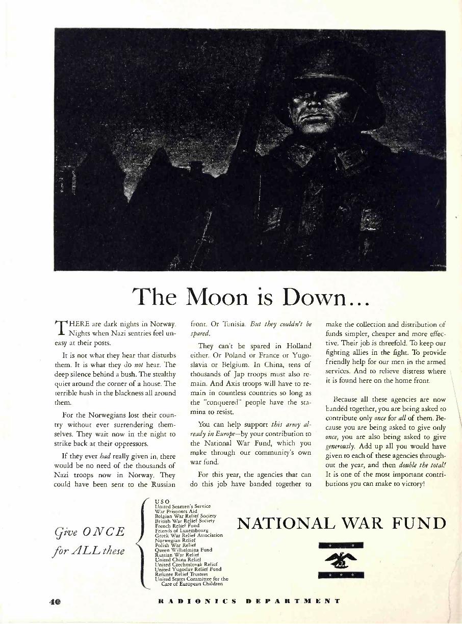
The Moon is Down... THERE are dark nights in Norway.
Nights when Nazi sentries feel un- easy at their posts.
It is not what they hear that disturbs them. It is what they do not hear. The deep silence behind a bush. The stealthy quiet around the corner of a house. The terrible hush in the blackness all around them.
For the Norwegians lost their coun- try without ever surrendering them- selves. They wait now in the night to strike back at their oppressors.
If they ever had really given in, there would be no need of the thousands of Nazi troops now in Norway. They could have been sent to the Russian
Give ONCE for ALL these
front. Or Tunisia. But they couldn't be
spared.
They can't be spared in Holland either. Or Poland or France or Yugo- slavia or Belgium. In China, tens of thousands of Jap troops must also re- main. And Axis troops will have to re- main in countless countries so long as
the "conquered" people have the sta- mina to resist.
You can help support this army al-
ready in Europe-by your contribution to the National War Fund, which you make through our community's own war fund.
For this year, the agencies that can do this job have banded together to
USO United Seamen's Service War Prisoners Aid Belgian War Relief Society British War Relief Society French Relief Fund Friends of Luxembourg Greek War Relief Association Norwegian Relief Polish War Relief Queen Wilhelmina Fund Russian War Relief United China Relief United Czechoslovak Relief United Yugoslav Relief Fund Refugee Relief Trustees United States Committee for the
Care of European Children
make the collection and distribution of funds simpler, cheaper and more effec- tive. Their job is threefold. To keep our fighting allies in the fight. To provide friendly help for our men in the armed services. And to relieve distress where it is found here on the home front.
Because all these agencies are now bandéd together, you are being asked to contribute only once for all of them. Be- cause you are being asked to give only once, you are also being asked to give generously. Add up all you would have given to each of these agencies through- out the year, and then double the total! It is one of the most important contri- butions you can make to victory!
NATIONAL WAR FUND * * *
* * *
1
40 RADIONICS DEPARTMENT