compact ac ac/dc digital clamp meter user manual read this manual before switching the unit on....
TRANSCRIPT

Please read this manual before switching the unit on.
Important safety information inside.
Compact AC
Digital
, AC/DC
Clamp MeterUser Manual
Compact AC
Digital
, AC/DC
Clamp MeterUser Manual

Compact AC AC DC Digital Clamp Meters User Manual, /
1.Safety....................................................................................2.Safety Notes..........................................................................3.Warnings...............................................................................4.Cautions................................................................................5.Meter Description.................................................................6.Operation.............................................................................7.AC/DC Current Measurements..............................................8.AC/DC Voltage Measurements..............................................9.Resistance Measurements.....................................................10.Diode and Continuity Measurements..................................11.Capacitance Measurements................................................12.Frequency measurements..................................................13.Temperature Measurements................................................14.Non-Contact AC Voltage Measurements.............................15.Mode Button.......................................................................16.Data Hold Button................................................................17.Rel Button...........................................................................18.Peak Hold............................................................................19.Battery Replacement...........................................................
Contents Page3333477888999101010101111
2

1 Safety
2 Safety Notes
3 Warnings
4 Cautions
International Safety SymbolsThis symbol, adjacent to another symbol or terminal, indicatesthe user must refer to the manual for further information.
This symbol, adjacent to a terminal, indicates that, undernormal use, hazardous voltages may be present
Double insulation
•Do not exceed the maximum allowable input range of any function•Do not apply voltage to meter when resistance function is selected.•Set the function switch OFF when the meter is not in use.
•Set function switch to the appropriate position before measuring.•When measuring volts do not switch to current/resistance modes.•When changing ranges using the selector switch always disconnect
the test leads from the circuit under test.•Do not exceed the maximum rated input limits.
Improper use of this meter can cause damage, shock, injury or death.Read and understand this user manual before operating the meter.Always remove the test leads before replacing the battery.Inspect the condition of the test leads and the meter itself for anydamage before operating the meter. Repair or replace any damagebefore use.Use great care when making measurements if the voltages are greaterthan 25VAC rms or 35VDC. These voltages are considered a shockhazard.Remove the battery if the meter is to be stored for long periods.Always discharge capacitors and remove power from the device undertest before performing Diode, Resistance or Continuity tests.
.
.
.
.
•
Compact AC AC DC Clamp Meters, / Digital User Manual
3
•Voltage checks on electrical outlets can be difficult and misleadingbecause of the uncertainty of connection to the recessed electricalcontacts. Other means should be used to ensure that the terminalsare not "live".
•If the equipment is used in a manner not specified by the manufacturer,the protection provided by the equipment may be impaired.
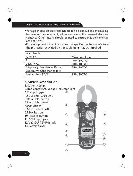
1.Current clamp2.Non-contact AC voltage indicator light3.Clamp trigger4.Rotary Function swith5.Data Hold button6.Back Light button7.LCD display8.MODE select button9.PEAK button10.Relative button11.COM input jack12.V
5 Meter Description
Ω CAP TEMPHz jack13.Battery Cover
•••
•
.
Input Limits
Function
A
V DC, V AC
Frequency, Resistance, Diode,
Continuity, Capacitance Test
Temperature (°C/°F)
Maximum Input
400A DC/AC
600V DC/AC
250V DC/AC
250V DC/AC
Compact AC AC DC Digital Clamp Meters User Manual, /
4
4
6
9
10
12
Hz
400A
40A
°C °F
COM
CAT III600V
VTempΩ Hz
REL
AC/DC TRMS CLAMP METER
1
2
3
5
7
11
13
8

1.AC DC AC (alternating current) and DC (direct currrent)2. Minus sign3. 4000 count (0 to 3999)
measurement reading with41segments Analog Bargraph
4.AUTO AutoRange mode5. Relative mode6. Diode test mode7. Audible Continuity8. Data Hold mode9.°C,°F, ,m,V,A,K,M, Units of measure list11.Hz % Frequency/duty cycle test mode12 MAX MIN MAX/MIN Hold mode12 Pmax Pmin Pmax Pmin Hold mode
Ω
.
.
μ
Range & Resolution
40.00 AAC
400.0 AAC
40.00 ADC
400.0 ADC
400.0 mVDC
4.000 VDC
40.00 VDC
400.0 VDC
600.0 VDC
400.0 mVAC
4.000 VAC
40.00 VAC
400.0 VAC
600.0 VAC
400.0
4.000 K
40.00 K
400.0 K
4.000 M
40.00 MΩ
Ω
Ω
Ω
Ω
Ω
Function
AC Current
(50/60Hz)
DC Current
DC Voltage
AC Voltage
(50/60Hz)
Resistance
Accuracy (% of reading)
± (2.5 % + 8 digits)
± (2.8 % + 5 digits)
± (2.5 % + 5 digits)
± (2.8 % + 5 digits)
± (0.8% + 2 digits)
± (1.5% + 2digits)
± (2 % + 2 digits)
± (1% + 10 digits)
± (1.5% + 5 digits)
± (2.0% + 5 digits)
± (1.0% + 4 digits)
± (1.5% + 2 digits)
± (2.5% + 3 digits)
± (3.5% + 5 digits)
Compact AC AC DC Digital Clamp Meters User Manual, /
5

Capacitance
Frequency
Temp (type-K)
(probe accuracy
not included)
40.00nF
400.0nF
4.000 F
40.00 F
400.0 F
4mF
10-100kHz
Sensitivity:100V(<50Hz);
50V(50 to 400Hz;15V
(401Hz to 100kHz)
-20 to 760°C
-4 to1400°F
μ
μ
μ
± (5.0% reading + 20 digits)
± (3% reading + 5 digits)
± (4.0% reading + 10 digits)
± (5.0% reading + 10 digits)
± (1.5% reading + 2 digits)
± (3%rdg+5°C)
± (3%rdg+9°F)
Clamp sizeDiode Test
Continuity CheckLow Battery IndicationOverrange IndicationMeasurements RateInput ImpedanceDisplayAC CurrentAC Voltage bandwidthOperating TemperatureStorage TemperatureOperating Humidity
Storage HumidityOperating AltitudeOver voltageBatteryAuto OFFDimensions/Weight
Opening ( ) approxTest current of 0.3mA typical; Opencircuit voltage <3V DC typical.Threshold <50 ; Test current <0.5mA“ ” is displayed“OL” is displayed2 per second, nominal10M (VDC and VAC)4000 counts LCD50-60Hz (TRMS AAC)50-60Hz ( TRMS VAC)
( )( )
Max 80% up to ( ) decreasinglinearly to 50% at ( )<80%
( ) maximum.Category III 600VOne 9V Batteryapprox. 30 minutes197x70x40mm/183g
Ω
Ω
30mm 1.2"
5 to 40°C 41 to 104°F-20 to 60°C -4 to 140°F
31°C 87°F40°C 104°F
2000meters 7000ft.
Compact AC AC DC Digital Clamp Meters User Manual, /
6

Safety For indoor use and in accordance withOvervoltage Category II, PollutionDegree 2. Category II includes local level,appliance, portable equipment, etc.,with transient overvoltages less thanOvervoltage Cat. III
6 Operation
7 AC/DC Current Measurements
Notices: Read and understand all warning and precaution statementslisted in the safety section of this operation manual prior to usingthis meter. Set the function select switch to the OFF position whenthe meter is not in use.
Warning: Ensure that the test leads aredisconnected from the meter before making currentclamp measurements.
Set the Function switch to the 400ADC/AC,40ADC/AC range.Select AC or DC with the MODE button.If the range of the measured is not known, select the higher rangefirst then move to the lower range if necessary.Press the trigger to openjaw. Fully enclose oneconductor to be measured.In DCA mode, to ensurethe reading is correct,please press REL button toclear the reading on LCDbefore measurement. Theclamp Meter LCD willDisplay the reading.
1.2.3.
4.
5.
.
.
3.
3.3.
3.3.3.3.3.3.
Hz
400A
40A
°C °F
COM
CAT III600V
VTemp
Ω Hz
REL
AC/DC TRMS CLAMP METER
Hz
400A
40A
°C °F
COM
CAT III600V
VTemp
Ω Hz
REL
AC/DC TRMS CLAMP METER
NO YES
Compact AC AC DC Digital Clamp Meters User Manual, /
7

Ω
8 AC/DC Voltage Measurements
9 Resistance Measurements
10 Diode and Continuity Measurements
Insert the black test lead into the negative COM terminal and thered test lead into the positive V terminal.Set the function switch to the V position.Select AC or DC with the MODE button.Connect the test leads in parallel to the circuit under test.Read the voltage measurement on the LCD display.
Insert the black test lead into the negative COM terminal and thered test lead into the positive terminal.Set the function switch to the position.Touch the test probe tips across the circuit or component undertest. It is best to disconnect one side of the device under test sothe rest of the circuit will not interfere with the resistance reading.For Resistance tests, read the resistance on the LCD display.
Insert the black test lead banana plug into the negative COM jackand the red test lead banana plug into the positive diode jack.Turn the rotary switch to the position.Press the MODE button until “ “ appears in the display.Touch the test probes to the diode under test. Forward voltagewill indicate 0.4V to 0.7V. Reverse voltage will indicate “OL”. Shorteddevices will indicate near 0mV and an open device will indicate “OL”in both polarities.For Continuity tests, if the resistance is < 50 , a tone will sound.
1.
2.3.4.5.
1.
2.3.
4.
1.
2.3.4.
Ω
.
.
.
1.
1.
1.1.
1.
1.1.1.1.
Red Black Black
Forward test Reverse test
Compact AC AC DC Digital Clamp Meters User Manual, /
8

1 .
1 .
1 .
1 Capacitance Measurements
2 Frequency measurements
3 Temperature Measurements
To avoid electric shock, disconnect power to the unit undertest and discharge all capacitors before taking any capacitancemeasurements. Remove the batteries and unplug the line cords.
Set the rotary function switch to the CAP position.Insert the black test lead banana plug into the negative (COM) jack.Insert the red test lead banana plug into the positive (V) jack.Touch the test leads to the capacitor to be tested.Read the capacitance value in the display
Set the rotary function switch to the “Hz” position.Insert the black lead banana plug into the negative COM jack andthe red test lead banana plug into the positive V jack.Touch the test probe tips to the circuit under test.Read the frequency on the display.
To avoid electric shock, disconnect both test probes fromany source of voltage before making a temperature measurement.
Set the function switch to °C °FInsert the Temperature Probe into the negative (COM) and the Vjacks, making sure to observe the correct polarity.Touch the Temperature Probe head to the part whose temperatureyou wish to measure. Keep the probe touching the part under testuntil the reading stabilizes (about 30 seconds).Read the temperature in the display. The digital reading will indicatethe proper decimal point and value.
To avoid electric shock, be sure the thermocouple hasbeen removed before changing to another measurement function
Warning:
1.2.
3.4.
1.2.
3.4.
Warning:
1.2.
3.
4.
Warning:
.
1.
1.
1.
1.1.
1.
Compact AC AC DC Digital Clamp Meters User Manual, /
9
1 .
1 .
1 .
1 .
4 Non-Contact AC Voltage Measurements
Mode Button
6 Data Hold Button
7 Rel Button
Risk of Electrocution. Before use, always test the VoltageDetector on a known live circuit to verify proper operation
Touch the probe tip to the hot conductor or insert into the hotside of the electrical outlet.If AC voltage is present, the detector light will illuminate.
The conductors in electrical cord sets are often twisted. Forbest results, rub the probe tip along a length of the cord to assureplacing the tip in close proximity to the live conductor.
The detector is designed with high sensitivity. Static electricityor other sources of energy may randomly trip the sensor. This isnormal operation
To select DC/ACV,OHM/ Diode/Continuity/CAP,
To freeze the LCD meter reading, press the data hold button. Thedata hold button is located on the left side of the meter (top button).While data hold is active, the H display icon appears on the LCD.Press the data hold button again to return to normal operation.
For DCA and Capacitance Zero & Offset adjustment.
Warning:
1.
2.Note:
Note:
.
.
5
1.
Compact AC AC DC Digital Clamp Meters User Manual, /
10

1 .
1 .
8 Peak Hold
9 Battery Replacement
The Peak Hold function captures the peak AC voltage or current.The meter can capture negative or positive peaks as fast as 1millisecond in duration.
Turn the function switch to the A or V position.Use the MODE button to select AC .Allow time for the display to stabilize.Press and Hold the PEAK button until “CAL” appears in the display.This procedure will zero the range selected.Press the PEAK button, Pmax will display.The display will update each time a higher positive peak occurs.Press the PEAK button again, Pmin will display. The display will nowupdate and indicate the lowest negative peak.To return to normal operation, press and hold the PEAK buttonuntil the Pmin or Pmax indicator switches off.
If the Function switch position is changed after a calibrationthe Peak Hold calibration must be repeated for the new functionselected.
Remove the one rear Phillips head screwOpen the battery compartmentReplace the Requires One 9V batteryRe-assemble the meter
1.2.3.4.
5.6.7.
8.
Note:
1.2.3.4.
1.
1.
1.
Compact AC AC DC Digital Clamp Meters User Manual, /
11

Rev.
090801
Compact AC AC DC Digital Clamp Meters User Manual, /