compact conductor systems vks and vkl - vahle · the conductor systems vks and vkl can be used for...
TRANSCRIPT

COMPACT CONDUCTOR SYSTEMSVKS AND VKL
3B | EN 2019

2

3
(1) Please enclose to your inquiry!
COMPACT CONDUCTOR SYSTEMS VKS AND VKL
CONTENTS VKS VKLGeneral .......................................................................................................... 4, 5 4, 6
Layout planning ............................................................................................. 7 7
Standard sections ......................................................................................... 8, 9 24
Curves ............................................................................................................ 10 24
Jointing material ............................................................................................ 10 25
Hangers ......................................................................................................... 11 25
End caps ........................................................................................................ 11 25
Feeds ............................................................................................................. 12, 13 25, 26
Transfer guides .............................................................................................. 14 –
Transfer funnels ............................................................................................ 15, 16 –
Expansion sections ....................................................................................... 16 –
Sectionalizing ................................................................................................ 17 25
Current collectors .......................................................................................... 17 26
Compact collectors ....................................................................................... 17, 18, 19 –
Accessories and spares for collectors ......................................................... 20, 21, 22 26
KTW-Systems................................................................................................. 26 26
Standard brackets ......................................................................................... 27 27
Snap-on brackets .......................................................................................... 27 27
7-pole VKS system for HRL ........................................................................... 28 –
Examples for ordering ................................................................................... 29, 30 29
Questionnaire ................................................................................................ 31 31

4
GENERAL
VAHLE conductor systems VKS and VKL are space saving conductor
systems, designed to prevent any accidental contact and hazard to per-
sonnel and are test finger proof to regulations VDE 0470, part 1 (EN
60529), protection code IP 21. They comply with the accident and VDE
regulations in electrical, mechanical and fire engineering cases. Collec-
tors are proof against accidental touch only when fully entered into con-
ductor rail.
Conductor system installations within reach of hand require a special
protection on the part of operator against accidental touch of current
collectors which are leaving the conductor rail (e. g. locking or cut-off
the power).
This is applicable for voltages above 25 V AC respectively 60 V DC.
The creeping distance between the conductors of the VKS-conductor is
30 mm. The different plastic housings hold from 3 to 6 copper or stain-
less steel conductors. Multiple conductor systems can be easily de-
signed by combining several plastic housings.
The minimal space required allows the systems to be integrated in the
crane or hoist track or in other special runway profiles. The minimal re-
quired space allows a direct layout in rail tracks or special track profiles.
The conductor systems VKS and VKL can be used for indoor and roof-
over (rain protected) applications. They can be installed with lateral or
suspended mounting and straight or curved tracks are available.
Approvals (VKS): UL-approval.
PLEASE NOTEPlease consult factory for galvanizing plants, pickling lines, other ag-
gressive or deep freeze ambients, as well as low voltage and data
transmission applications, indicating special environmental condi-
tions.
To speed up quotations and order processing, we would appreci-
ate receiving your drawings or sketches for conductor systems with
curves, dead sections, turntables, switches, etc.
Please use our questionnaire on page 31.
(1) Consult factory for use below 0°C (32° F)(2) 80 % ED(3) Not with UL-approval; UUL= 600 V
Electrical properties VKS VKL
Max. ampacity 140 A(2) 30 A
Allowed voltage 690 V(3) 400 V
Electrical strength DIN 53481
>25 kV/mm
Special electrical strength IEC 60093
1 x 10¹⁴ Ohm x cm
Surface resistance IEC 60093 2,1 x 10¹³ Ohm
Creep resistance IEC 60112 CTI > 400
Flammability Flame resistant, self extinguishing, UL 94 V0
Conductor material
Cross section mm2
Impedance 50 Hz Ohm/1000 m
Resistance Ohm/1000 m
Copper 16 1.107 1.102
25 0.730 0.723
30 0.603 0.595
35 0.520 0.510
Mechanical properties N/mm2
Flexible strength 70 – 80
Tensile strength 40 – 53
Chemical resistance of the isolating profile at +45°C ambient temperature
Benzine, petroleum, fats resistant
Caustic soda up to 50 % resistant
Hydrochloric acid, concent resistant
Sulfuric acid up to 50 % resistant
Water absorption %
max. at 100°C 1
max. at 20°C 0.06
Ambient temperature range °C
Rail length up to 4 m –30(1) up to +55
Rail length > 4 m von 0(1) up to +40
5
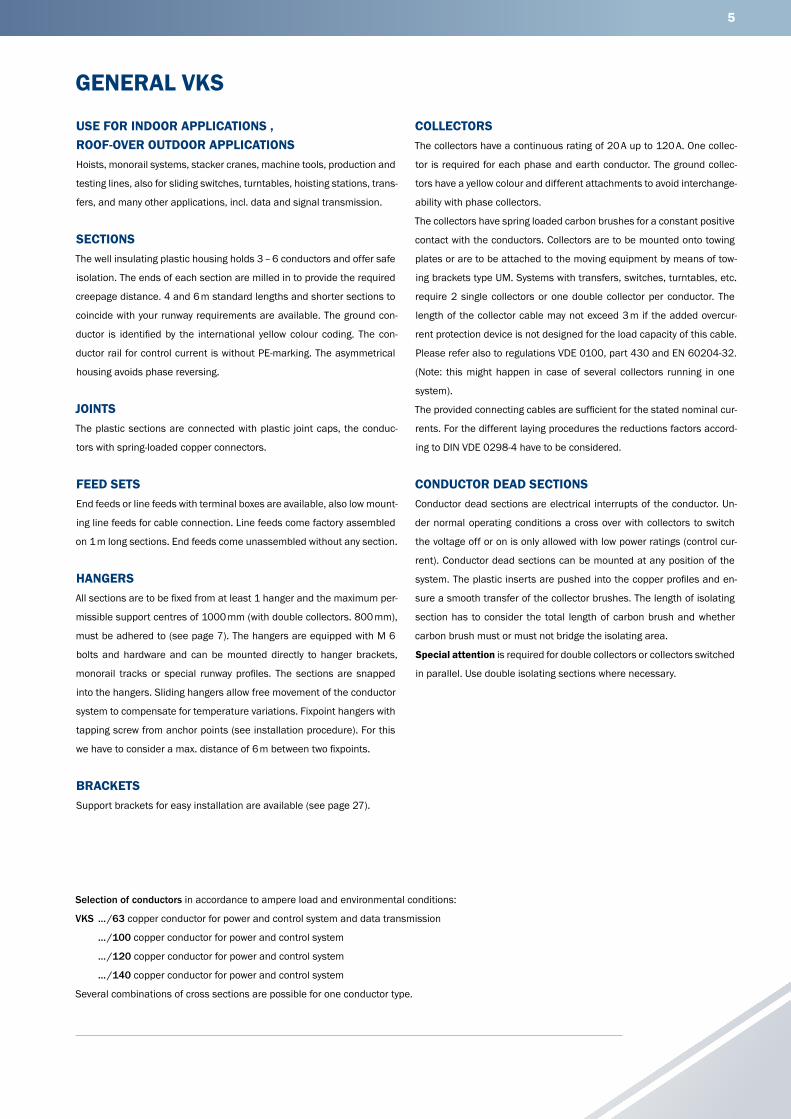
GENERAL VKS
USE FOR INDOOR APPLICATIONS , ROOF-OVER OUTDOOR APPLICATIONSHoists, monorail systems, stacker cranes, machine tools, production and
testing lines, also for sliding switches, turntables, hoisting stations, trans-
fers, and many other applications, incl. data and signal transmission.
SECTIONSThe well insulating plastic housing holds 3 – 6 conductors and offer safe
isolation. The ends of each section are milled in to provide the required
creepage distance. 4 and 6 m standard lengths and shorter sections to
coincide with your runway requirements are available. The ground con-
ductor is identified by the international yellow colour coding. The con-
ductor rail for control current is without PE-marking. The asymmetrical
housing avoids phase reversing.
JOINTSThe plastic sections are connected with plastic joint caps, the conduc-
tors with spring-loaded copper connectors.
FEED SETSEnd feeds or line feeds with terminal boxes are available, also low mount-
ing line feeds for cable connection. Line feeds come factory assembled
on 1 m long sections. End feeds come unassembled without any section.
HANGERSAll sections are to be fixed from at least 1 hanger and the maximum per-
missible support centres of 1000 mm (with double collectors. 800 mm),
must be adhered to (see page 7). The hangers are equipped with M 6
bolts and hardware and can be mounted directly to hanger brackets,
monorail tracks or special runway profiles. The sections are snapped
into the hangers. Sliding hangers allow free movement of the conductor
system to compensate for temperature variations. Fixpoint hangers with
tapping screw from anchor points (see installation procedure). For this
we have to consider a max. distance of 6 m between two fixpoints.
BRACKETSSupport brackets for easy installation are available (see page 27).
COLLECTORSThe collectors have a continuous rating of 20 A up to 120 A. One collec-
tor is required for each phase and earth conductor. The ground collec-
tors have a yellow colour and different attachments to avoid interchange-
ability with phase collectors.
The collectors have spring loaded carbon brushes for a constant positive
contact with the conductors. Collectors are to be mounted onto towing
plates or are to be attached to the moving equipment by means of tow-
ing brackets type UM. Systems with transfers, switches, turntables, etc.
require 2 single collectors or one double collector per conductor. The
length of the collector cable may not exceed 3 m if the added overcur-
rent protection device is not designed for the load capacity of this cable.
Please refer also to regulations VDE 0100, part 430 and EN 60204-32.
(Note: this might happen in case of several collectors running in one
system).
The provided connecting cables are sufficient for the stated nominal cur-
rents. For the different laying procedures the reductions factors accord-
ing to DIN VDE 0298-4 have to be considered.
CONDUCTOR DEAD SECTIONSConductor dead sections are electrical interrupts of the conductor. Un-
der normal operating conditions a cross over with collectors to switch
the voltage off or on is only allowed with low power ratings (control cur-
rent). Conductor dead sections can be mounted at any position of the
system. The plastic inserts are pushed into the copper profiles and en-
sure a smooth transfer of the collector brushes. The length of isolating
section has to consider the total length of carbon brush and whether
carbon brush must or must not bridge the isolating area.
Special attention is required for double collectors or collectors switched
in parallel. Use double isolating sections where necessary.
Selection of conductors in accordance to ampere load and environmental conditions:
VKS … /63 copper conductor for power and control system and data transmission
… /100 copper conductor for power and control system
… /120 copper conductor for power and control system
… /140 copper conductor for power and control system
Several combinations of cross sections are possible for one conductor type.

6
GENERAL VKL
USE INDOOR APPLICATIONSDesigned for small current loads and serve for the power supply of light
cranes and for control current systems. The VKL conductor rail can also
be used for hoists, jib cranes, power tools, machine tools, electrically
operated gates, testing lines, and other applications.
SECTIONSThe plastic housing holds up to 5 conductors. The ground conductor is
identified by international yellow colour code. 4 m standard lengths and
shorter sections to coincide with your runway requirements are available.
The straight sections are restricted as follows:
1. Max. system length: L = 100 m
2. From the curve to system end: max. L = 50 m
3. Between 2 curves: max. L = 15 m
The ends of each section are milled in to provide the required creepage
distance. End caps, fixed with screws, can be installed to every section
JOINTSThe mechanical jointing of the conductor rail housing is done by means
of a two-piece plastic joint cap. The conductors get spring-loaded copper
connectors.
FEEDSThe feeds are available as end or line feeds. They are mounted on a 1 m
section.
SUPPORTSMaximum support distance of 1000 mm must be kept. The support
hanger consists of a pvc part with a fixing screw and is arranged as
a sliding hanger. The fixpoint in the middle of the system consists of a
hanger with a locating clamp on each side of the hanger.
BRACKETSTo support the conductor rail to the crane track mounting brackets avail-
able (siehe Seite 27).
COLLECTORSThe glider type collectors are guided at the PVC housing. They are sup-
plied with 1 m long connecting cable. Longer cables are available upon
request. The carbon brushes have a continuous current capacity of 10 A
(15 A at 60 % intermittent duty). Use two collectors for higher ratings. The
towing arm is the mechanical flexible connection between collector and
moving equipment.
The length of the collector cable should not exeed 3 m if the installed
fuse is not suitable for the cross section of this connecting cable. See
DIN VDE 0100, Teil 430 und DIN EN 60204-32. (Please note: This is
often the fact if more than one collector is used in the system)
The provided connecting cables are sufficient for the stated nominal cur-
rents. For the different laying procedures the reductions factors accord-
ing to DIN VDE 0298-4 have to be considered.
DEAD SECTIONSDead sections for control lines can be installed according to your in-
structions.

7
LAYOUT PLANNING FOR VKS AND VKL
L 4
L3
15
L5
L2 L1
L
End cap Line feedVLS/VLE
Joint materialSVN/LV
Sliding or fi xpoint hangers
End feedVEKS/VEK
Line feed VNS/VNKTransfer guides
L = Conductor rail section (Standard lengths: 1 m, 2 m, 3 m, 4 m, 5 m, 6 m or cut to suit the system)
L1 = Support spacing for straight runs: max. 1 m for curved runs: max. 0.5 m
L2 = Extending length (max. 200 mm)L3 = Air gap for transfers, e. g. switches and dropout sections (3–5 mm)L4 = Space to remove feed box cover, if applicableL5 = Clearance for expansion of conductor system
(min. 50 mm for VKS; min. 150 mm for VKL).
MAX. SUPPORT SPACINGSYMBOLS IN LAYOUT PLANS
VKS VKL
Track – –
Conductor rail VKS VKL
Joint material SVN –
Joint material – LV
Fixpoint hanger VEPS VEP
Sliding hanger VAS VA
End cap VES VE
End feed, power VEKS VEK
End feed, control VEKS VEK
Line feed, power VNS VNK
Line feed, control VNS VNK
Line feed, power and control
VLS VLE
Transfer guide, straight VU –
Transfer guide, oblique VUS –
Transfer funnel VEM –
Expansion section DVKS –
Isolating assembly VSTS VST
at KSTU 30-55 (Fig. 1) VKS VKL
for straight runs 1000 mm 800 mm
1000 mm
for curved runs 500 mm400 mm
500 mm
Fig. 1A < 300 mm Support spacing 0.8 mA > 300 mm Support spacing 1.0 m
SYSTEM LAYOUT
AA
8
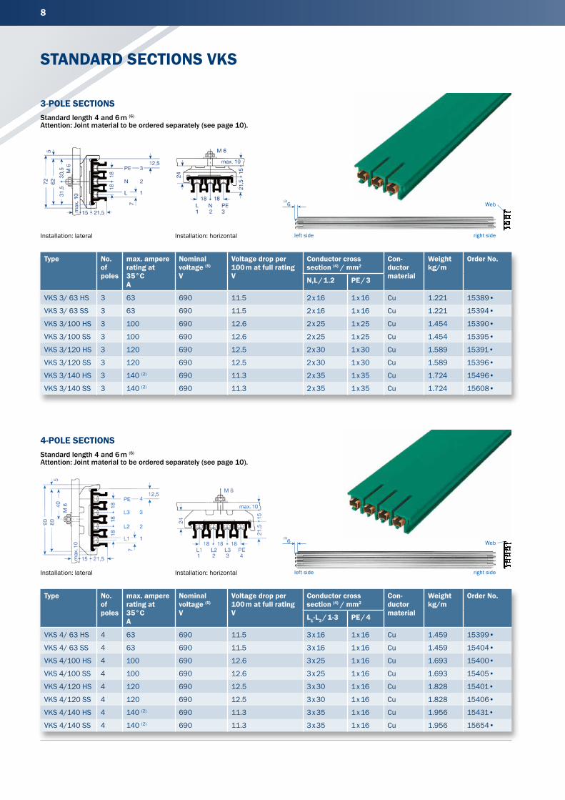
STANDARD SECTIONS VKS
Type No. of poles
max. ampere rating at 35°C A
Nominal voltage (5) V
Voltage drop per 100 m at full rating V
Conductor cross section (4) / mm2
Con-ductor material
Weight kg/m
Order No.
N,L / 1.2 PE / 3
VKS 3/ 63 HS 3 63 690 11.5 2 x 16 1 x 16 Cu 1.221 15389•
VKS 3/ 63 SS 3 63 690 11.5 2 x 16 1 x 16 Cu 1.221 15394•
VKS 3/100 HS 3 100 690 12.6 2 x 25 1 x 25 Cu 1.454 15390•
VKS 3/100 SS 3 100 690 12.6 2 x 25 1 x 25 Cu 1.454 15395•
VKS 3/120 HS 3 120 690 12.5 2 x 30 1 x 30 Cu 1.589 15391•
VKS 3/120 SS 3 120 690 12.5 2 x 30 1 x 30 Cu 1.589 15396•
VKS 3/140 HS 3 140 (2) 690 11.3 2 x 35 1 x 35 Cu 1.724 15496•
VKS 3/140 SS 3 140 (2) 690 11.3 2 x 35 1 x 35 Cu 1.724 15608•
3-POLE SECTIONSStandard length 4 and 6 m (6) Attention: Joint material to be ordered separately (see page 10).
Installation: lateral Installation: horizontal
Type No. of poles
max. ampere rating at 35°C A
Nominal voltage (5) V
Voltage drop per 100 m at full rating V
Conductor cross section (4) / mm2
Con-ductor material
Weight kg/m
Order No.
L1-L3 / 1-3 PE / 4
VKS 4/ 63 HS 4 63 690 11.5 3 x 16 1 x 16 Cu 1.459 15399•
VKS 4/ 63 SS 4 63 690 11.5 3 x 16 1 x 16 Cu 1.459 15404•
VKS 4/100 HS 4 100 690 12.6 3 x 25 1 x 16 Cu 1.693 15400•
VKS 4/100 SS 4 100 690 12.6 3 x 25 1 x 16 Cu 1.693 15405•
VKS 4/120 HS 4 120 690 12.5 3 x 30 1 x 16 Cu 1.828 15401•
VKS 4/120 SS 4 120 690 12.5 3 x 30 1 x 16 Cu 1.828 15406•
VKS 4/140 HS 4 140 (2) 690 11.3 3 x 35 1 x 16 Cu 1.956 15431•
VKS 4/140 SS 4 140 (2) 690 11.3 3 x 35 1 x 16 Cu 1.956 15654•
Installation: lateral Installation: horizontal
4-POLE SECTIONSStandard length 4 and 6 m (6) Attention: Joint material to be ordered separately (see page 10).
6(3)
Web
right sideleft side
6(3)
Web
right sideleft side

9
5- AND 6-POLE SECTIONSStandard length 4 and 6 m (6)
Attention: Joint material to be ordered separately (see page 10).
15 21,5
ma
10
12,5
1818
1818
18
126
116
5034
M6
5
7
6
5
4
3
2
1
2
1
PE
L3
L2
L1
x.
Installation: lateral
18 18 18 18 18L1 L2 L3 PE 1 21 2 3 4 5 6
M 6
max. 1
1521
,5
24
0
Installation: horizontal
Type No. ofpoles
max. ampere rating at 35°C A
Nominal voltage (5) V
Voltage drop per 100 m at full rating V
Conductor cross section (4) / mm2
Con-ductor material
Weight kg/m
Order No.
L1-L3 / 1-3
PE / 4 1.2 / 5.6
VKS 5/ 63 HS (1) 5 63 690 11.5 3 x 16 1 x 16 1 x 16 Cu 2.058 15409•
VKS 5/ 63 SS (1) 5 63 690 11.5 3 x 16 1 x 16 1 x 16 Cu 2.058 15414•
VKS 5/100 HS (1) 5 100 690 12.6 3 x 25 1 x 16 1 x 16 Cu 2.292 15410•
VKS 5/100 SS (1) 5 100 690 12.6 3 x 25 1 x 16 1 x 16 Cu 2.292 15415•
VKS 5/120 HS (1) 5 120 690 12.5 3 x 30 1 x 16 1 x 16 Cu 2.427 15411•
VKS 5/120 SS (1) 5 120 690 12.5 3 x 30 1 x 16 1 x 16 Cu 2.427 15416•
VKS 5/140 HS (1) 5 140 (2) 690 11.3 3 x 35 1 x 16 1 x 16 Cu 2.549 15487•
VKS 5/140 SS (1) 5 140 (2) 690 11.3 3 x 35 1 x 16 1 x 16 Cu 2.549 15655•
VKS 6/ 63 HS 6 63 690 11.5 3 x 16 1 x 16 2 x 16 Cu 2.202 15419•
VKS 6/ 63 SS 6 63 690 11.5 3 x 16 1 x 16 2 x 16 Cu 2.202 15424•
VKS 6/100 HS 6 100 690 12.6 3 x 25 1 x 16 2 x 16 Cu 2.436 15420•
VKS 6/100 SS 6 100 690 12.6 3 x 25 1 x 16 2 x 16 Cu 2.436 15425•
VKS 6/120 HS 6 120 690 12.5 3 x 30 1 x 16 2 x 16 Cu 2.571 15421•
VKS 6/120 SS 6 120 690 12.5 3 x 30 1 x 16 2 x 16 Cu 2.571 15426•
VKS 6/140 HS 6 140 (2) 690 11.3 3 x 35 1 x 16 2 x 16 Cu 2.693 15260•
VKS 6/140 SS 6 140 (2) 690 11.3 3 x 35 1 x 16 2 x 16 Cu 2.693 15656•
(1) VKS 5 eliminates conductor number 6; plastic housing however identical to VKS 6.(2) 80 % ED(3) Section is superseded 6 mm at 20°C UT.(4) Same cross section at PE (ground) when used for control line. Other conductor combinations are possible.(5) Not with UL-approval; UUL= 600 V(6) For supply lengths above 4 m refer to restricted ambient temperature (page 4).• Suffix types e. g. 2 m VKS 4/120 with PE R VKS 4/120 -2 HS- Order No. 154012. Shorter sections are made up from the next larger standard length.X Only for conductor system without PE-marking
6(3) Web
right sideleft side

10
(1) Curved sections will be factory prepared with a 100 mm straight section on both ends. Horizontal curves with more than 90 degrees should be divided in two or more sections.
CURVED SECTIONS, JOINT MATERIAL VKS
Type No. of poles Weight kg Order No.
SVN 3/ 63 - 100 3 0.112 156533
SVN 3/120 - 140 3 0.112 156534
JOINT MATERIAL3-pole
100
100
JOINT MATERIAL4-pole
Type No. of poles Weight kg Order No.
SVN 4/ 63 - 100 4 0.136 156535
SVN 4/120 - 140 4 0.136 156536
100
Type No. of poles Weight kg Order No.
SVN 5/ 63 - 100 5 0.180 156537
SVN 5/120 - 140 5 0.180 156538
SVN 6/ 63 - 100 6 0.194 156539
SVN 6/120 - 140 6 0.194 156540
JOINT MATERIAL5- and 6-pole
CURVED SECTIONS (2)
per your layout drawing max. L = 3.60 m, support spacing: ~ 500 mm, max. angle 180°
CURVED SECTIONS (2)
4-pole Configuration as shown above!
Type Rmm
Surcharge Order No. VKS 4
Horizontal curve, right 400 – 900 150389
Horizontal curve, left 400 – 900 150391
Horizontal curve, right >900 153717
Horizontal curve, left >900 150110
Inside curve 200 – 800 150392
Inside curve >800 153718
Outside curve 200 – 800 150393
Outside curve >800 150100
CURVED SECTIONS (2)
5- and 6-pole Configuration as shown above!
Type R Surcharge Order No.
mm VKS 5 VKS 6
Horizontal curve, right 400 – 900 150394 150398
Horizontal curve, left 400 – 900 150395 150399
Horizontal curve, right >900 153719 153721
Horizontal curve, left >900 152090 152110
Inside curve 200 – 800 150396 150401
Inside curve >800 153720 153722
Outside curve 200 – 800 150397 150402
Outside curve >800 152080 152100
CURVED SECTIONS (2)
3-pole
Type R mm
Surcharge Order No. VKS 3
Horizontal curve, right 400 – 900 150385
Horizontal curve, left 400 – 900 150386
Horizontal curve, right > 900 153120
Horizontal curve, left > 900 153130
Inside curve 200 – 800 150387
Inside curve > 800 153040
Outside curve 200 – 800 150388
Outside curve > 800 153050
R
Web
Inside curve: R Outside curve: R
Web

11
(1) Complete with hardware (bolts, nuts, spring washers). Support spacing see page 7.(2) L = loose; c/w hardware
M = Factory assembled
HANGERS, END CAP VKS
Type Weight kg Order No.
VEPS 4 0.046 150120
FIXPOINT HANGER (1)
4-pole with tapping screw and clamp
15
M 6
20
30 tapping screwand clamp
Type Weight kg Order No.
VAS 4 0.040 150130
SLIDING HANGER (1)
4-pole
15
M 6
20
30
Type Weight kg Order No.
VES 4 - L 0.039 150140
VES 4 - M 0.039 152022
END CAP (2)
4-pole suitable left and right
4813 Section
Type Weight kg Order No.
VEPS 6 0.062 152120
FIXPOINT HANGER (1)
6-pole with tapping screw and clamp
15
M 6
20
30tapping screwand clamp
Type Weight kg Order No.
VAS 6 0.056 152130
SLIDING HANGER (1)
6-pole
15
M 6
20
30
Type Weight kg Order No.
VES 6 - L 0.051 152140
VES 46 - M 0.051 152021
END CAP (2)
6-pole suitable left and right
4813
Section
FIXPOINT HANGER (1)
3-pole with tapping screw and clamp
15
M 6
20
30 tapping screwand clamp
Type Weight kg Order No.
VEPS 3 0.042 153070
SLIDING HANGER (1)
3-pole
15
M 6
20
30
Type Weight kg Order No.
VAS 3 0.036 153060
END CAP (2)
3-pole suitable left and right
Type Weight kg Order No.
VES 3 - L 0.033 153080
VES 3 - M 0.033 152023
4813 Section

12
(1) End feeds loose as components. Sections are to be ordered separately (see page 8).(2) Cable gland ST - M40 x 1,5 for Ø = 19–28 mm ST - M20 x 1,5 for Ø = 7–13 mm
Terminal cross section Phase = 35 mm2
PE = 35 mm2
FEEDS VKS
END FEED (1)
3-pole Terminal box with terminal clamps
100 13
190
150Section
100 13
190
150Section
100 13
190
150Section
END FEED (1)
4-pole Terminal box with terminal clamps
END FEED (1)
5- and 6-pole Terminal box with terminal clamps
Type Cable gland (2) Ampacity A Weight kg Order No.
VEKS 3/63 - 120 L ST-M 40 x 1.5 63 - 120 1.150 156422
Surcharge for assembling 156423
Type Cable gland (2) Ampacity A Weight kg Order No.
VEKS 4/63 - 120 L ST-M 40 x 1.5 63 - 120 1.230 156421
Surcharge for assembling 156423
Type Cable gland (2) Ampacity A Weight kg Order No.
VEKS 5/63 - 120 L ST-M 40 x 1.5ST-M 20 x 1.5
63 - 120 1.380 156420
VEKS 6/63 - 120 L ST-M 40 x 1.5ST-M 20 x 1.5
63 - 120 1.460 156419
Surcharge for assembling 156423
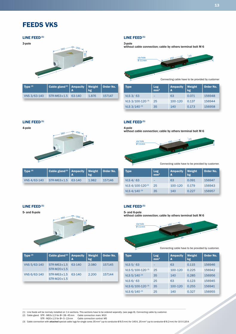
13
(1) Line feeds will be normaly installed on 1 m sections. This sections have to be ordered seperatly. (see page 8). Connecting cable by customer.(2) Cable gland STR - M63 x 1,5 for Ø= 28–45 mm Cable connection main: M10 STR - M20 x 1,5 for Ø= 5–13 mm Cable connection control: M5(3) Cable connection with attached special cable lugs for single cores 35 mm2 (up to conductor-Ø 8.5 mm) for 140 A, 25 mm2 (up to conductor-Ø 8.2 mm) for 10 0-120 A
FEEDS VKS
LINE FEED (1)
3-pole without cable connection; cable by others terminal bolt M 6
Type Lug mm2
Ampacity A
Weightkg
Order No.
VLS 3/ 63 – 63 0.071 156948
VLS 3/100-120 (3) 25 100 -120 0.137 156944
VLS 3/140 (3) 35 140 0.173 156958
Connecting cable have to be provided by customer
LINE FEED (1)
4-pole without cable connection; cable by others terminal bolt M 6
Type Lug mm2
Ampacity A
Weight kg
Order No.
VLS 4/ 63 – 63 0.091 156947
VLS 4/100-120 (3) 25 100 -120 0.179 156943
VLS 4/140 (3) 35 140 0.227 156957
Connecting cable have to be provided by customer.
LINE FEED (1)
5- and 6-pole without cable connection; cable by others terminal bolt M 6
Type Lug mm2
Ampacity A
Weight kg
Order No.
VLS 5/ 63 – 63 0.115 156946
VLS 5/100-120 (3) 25 100 -120 0.225 156942
VLS 5/140 (3) 35 140 0.285 156956
VLS 6/ 63 25 63 0.123 156945
VLS 6/100-120 (3) 35 100 -120 0.255 156941
VLS 6/140 (3) 25 140 0.327 156955
Connecting cable have to be provided by customer.
150
=
=
200360
Type (2) Cable gland (2) Ampacity A
Weight kg
Order No.
VNS 4/63-140 STR-M63 x 1.5 63-140 1.982 157146
LINE FEED (1)
4-pole
=
=
150
200360
LINE FEED (1)
5- and 6-pole
Type (2) Cable gland (2) Ampacity A
Weight kg
Order No.
VNS 5/63-140 STR-M63 x 1.5STR-M20 x 1.5
63-140 2.080 157145
VNS 6/63-140 STR-M63 x 1.5STR-M20 x 1.5
63-140 2.200 157144
=
=
150
200360
Type (2) Cable gland (2) Ampacity A
Weight kg
Order No.
VNS 3/63-140 STR-M63 x 1.5 63-140 1.876 157147
LINE FEED (1)
3-pole
=
=
150 15via holeØ 11 mm
=
=
15015
via holeØ 11 mm
=
=
15015
via holeØ 11 mm
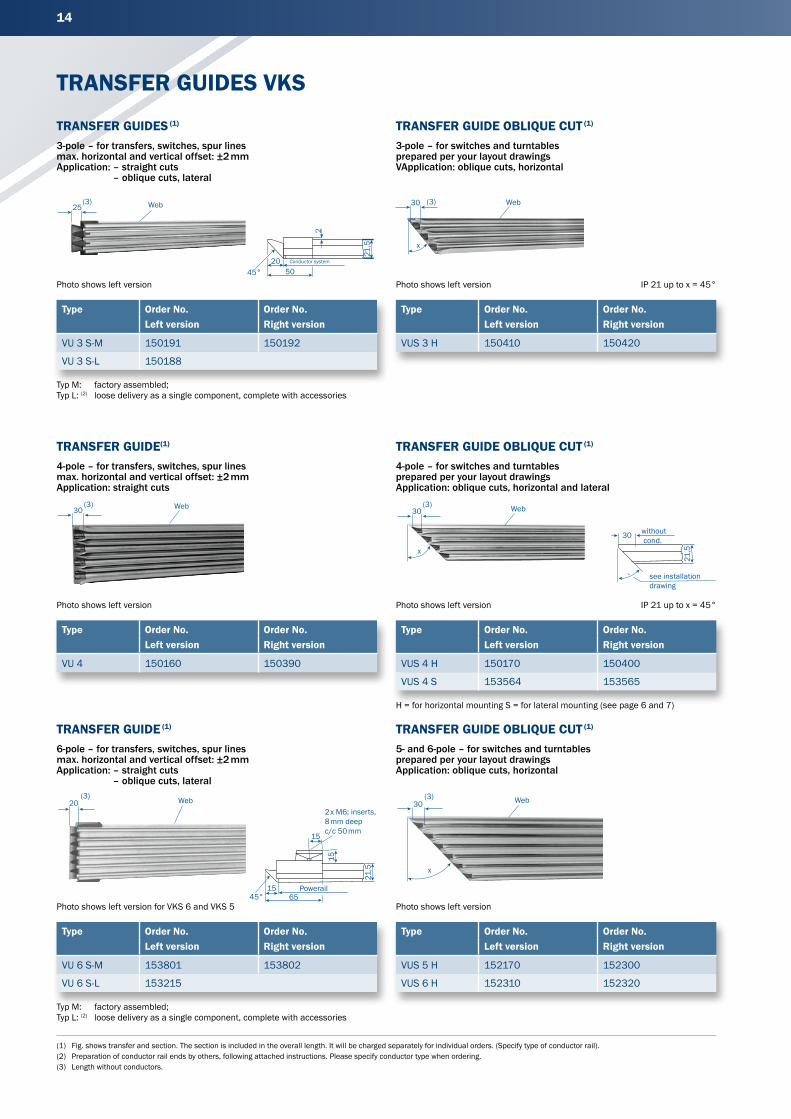
14
(1) Fig. shows transfer and section. The section is included in the overall length. It will be charged separately for individual orders. (Specify type of conductor rail).(2) Preparation of conductor rail ends by others, following attached instructions. Please specify conductor type when ordering.(3) Length without conductors.
TRANSFER GUIDES VKS
TRANSFER GUIDES (1)
3-pole – for transfers, switches, spur lines max. horizontal and vertical offset: ±2 mm Application: – straight cuts
– oblique cuts, lateral
Photo shows left version
Typ M: factory assembled;Typ L: (2) loose delivery as a single component, complete with accessories
Type Order No. Order No.Left version Right version
VU 3 S-M 150191 150192
VU 3 S-L 150188
TRANSFER GUIDE OBLIQUE CUT (1)
3-pole – for switches and turntables prepared per your layout drawings VApplication: oblique cuts, horizontal
Photo shows left version IP 21 up to x = 45°
Type Order No. Order No.Left version Right version
VUS 3 H 150410 150420
TRANSFER GUIDE OBLIQUE CUT (1)
4-pole – for switches and turntables prepared per your layout drawings Application: oblique cuts, horizontal and lateral
Type Order No. Order No.Left version Right version
VUS 4 H 150170 150400
VUS 4 S 153564 153565
H = for horizontal mounting S = for lateral mounting (see page 6 and 7)
Photo shows left version IP 21 up to x = 45°
TRANSFER GUIDE(1)
4-pole – for transfers, switches, spur lines max. horizontal and vertical offset: ±2 mm Application: straight cuts
Type Order No. Order No.Left version Right version
VU 4 150160 150390
Photo shows left version
Photo shows left version
TRANSFER GUIDE OBLIQUE CUT (1)
5- and 6-pole – for switches and turntables prepared per your layout drawings Application: oblique cuts, horizontal
Type Order No. Order No.Left version Right version
VUS 5 H 152170 152300
VUS 6 H 152310 152320
TRANSFER GUIDE (1)
6-pole – for transfers, switches, spur lines max. horizontal and vertical offset: ±2 mm Application: – straight cuts
– oblique cuts, lateral
Type Order No. Order No.Left version Right version
VU 6 S-M 153801 153802
VU 6 S-L 153215
Photo shows left version for VKS 6 and VKS 5
Typ M: factory assembled;Typ L: (2) loose delivery as a single component, complete with accessories
30 (3)
x
Web
(3)30 Web
(3)30
x
Web
45°20
50
21,5
2
Conductor system
30
21,5
see installation
without cond.
drawing
20(3) Web
6545°15
21,5
15
15
Powerail
2 x M6; inserts,8 mm deepc/c 50 mm
(3)30
x
Web
(3)25 Web

15
(1) Conductor rail section must be factory prepared. Order separately for left hand VU … L, for right hand VU … R.(2) Higher speeds on request
TRANSFER FUNNELS FOR KSTU 30/55for max. speed v = 100 m/min.(2)
TRANSFER FUNNELS VKS
Type A mm B mm C mm D mm Weight kg Order No. VU ... L(1) VU ... R(1)
EFT V3 - KSTU 62 148 175 198 3.140 156144 150370 150380
EFT V4 - KSTU 80 166 193 216 3.320 156145 150160 150390
EFT V6 - KSTU 116 202 229 252 3.680 156146 152280 152290
20
82
681
82,5
24
max. 800
35
9,4°
C A
1818
1818
18
375
40
64
B D
Slotted hole7 x 15

16
(1) Conductor rail section must be factory prepared. Order separately for left hand VU … L, or for right hand VU … R.(2) Higher speeds on request.(3) Suffix types e. g. DVKS 3/10 with PE DVKS 3/60 HS Order No. 153230.
“A“(0–50 mm)
1000 (±25)
TRANSFER FUNNELS / EXPANSION SECTIONS VKS
TRANSFER FUNNELS FOR KSFU 25 (1)
for max. speed v = 100 m/min.(2)
Type A mm B mm C mm D mm Weight kg Order No. VU ... L(1) VU ... R(1)
EFT V3 - KSFU 25 62 120 108 162 1.400 153337 150370 150380
EFT V4 - KSFU 25 80 138 126 180 1.520 153336 150160 150390
EFT V5 - KSFU 25 98 156 144 198 1.640 156132 152160 152270
EFT V6 - KSFU 25 116 174 162 216 1.760 153335 152280 152290
EXPANSION SECTIONS
Application
Expansion sections are required to compensate for expansion and contraction in
system expansion gaps (building or track). The expansion capacity is 50 mm. More
tolerance require more than one VKS expansion section. They do not interrupt
electrical power, so there is no need for an extra feeding. Expansion joints do not
influence the voltage drop of a system.
Mounting
The expansion section is installed in the center between two fix points in the
building/track expansion gap area. The gap dimension “A” equals the gap of the
building/track. The remaining conductor rail is laid according to the installation
instructions. Sketch 1
Type (3) Weight Order No. Order No. Type (3) Weight Order No. Order No.kg (with PE) (without PE) kg (with PE) (without PE)
HS SS HS SS
DVKS 3/ 63 1.900 153230 153240 DVKS 5/ 63 3.266 152340 152380
DVKS 3/ 100 2.090 153250 150551 DVKS 5/ 100 3.586 152350 150554
DVKS 3/ 120 2.215 153623 150552 DVKS 5/ 120 3.811 153633 150555
DVKS 3/ 140 2.346 156588 156589 DVKS 5/ 140 4.030 156596 156597
DVKS 4/ 63 2.412 150480 150510 DVKS 6/ 63 3.582 152360 152390
DVKS 4/ 100 2.622 150490 150516 DVKS 6/ 100 3.962 152370 150556
DVKS 4/ 120 2.852 153628 150553 DVKS 6/ 120 4.242 153638 150557
DVKS 4/ 140 3.027 156590 156595 DVKS 6/ 140 4.504 156598 156599
4000 975–1025 4000
Expansion gap
Expansion section
Fixpoint hanger
10
85
335
60,5
24
max. 80035
15º
C A
1818
1818
18
154,530
64
B D
4
Slotted hole 7 x 15
Powerail with transfer guide VU is to beordered seperately

17
(1) Description of conductor profiles see page 8.(2) Length of the currentless track (longer designs on request).(3) Types to be completed e.g. KSTU 30 R KSTU 30 PH Order No. 152087(4) Only with 5 and 6-pole version.
SECTIONALIZING / CURRENT COLLECTOR VKS
30(2)
CONDUCTOR DEAD SECTION(1) Position of the conductor dead section and item number of the conduc-
tor profile which has to be seperated have to be advised by ordering.
M = factory assembled
Type Order No. Colour
VSTS 1/10-63 M 156993 black
VSTS 1/100 M 150150 black
VSTS 1/120 M 151674 black
VSTS 1/140 M 156335 black
COLLECTORwith 2 m connecting cable; contact pressure: ca. 5 N
For transfer funnels EFT V ... -KSTU
(in funnel area ±10 to all sides)
Typ (3) Ampacity Connecting cable Lift & Swivel Weight Order No.A A/ d max/ deflection kg Phase PE
mm2 mm mm black yellow
KSTU 30 30 2.50 5 ±20 0.240 152087 152088
KSTU 55 55 6.00 11 ±20 0.368 154441 154442
For double arrangement of current collectors and support spacing for conductor system see page 5.
COMPACT COLLECTORwith 1 m connecting cable for transfer funnel EFT V … –KSFU 25
(in funnel area ±10 to all sides)
Phase distance 18 mm
Lift and swivel deflection ±15 mm
Contact pressure: ca. 3.5 N per carbon
PE on No. 4, with 3-poles on No. 3, other arrangements possible
PE is first contact while entering conductor rail
Type (3) Pol- Order No.es a b Weight with PE without PE
mm mm kg HS ST
KSFU 25-2 2 18 43 0.182 155050 155059
KSFU 25-3 3 54 79 0.295 155051 155060
KSFU 25-4 4 54 79 0.352 155052 155061
KSFU 25-5 5 80 115 0.460 155053 155062
KSFU 25-6 6 80 115 0.517 155054 155063
Separately available: PH PE
Collector KSFU 25 155025 155026
140 (190)
12
85 (9
5)
8560
17,8
4,4
18
65
43
2
1
RF 3
max. 138
max. 18
DF 2
ba
53 (4)
1588
71
4215
7
Flat Plug6,3 x 0,8FLA 2,5

18
(1) Types to be completed e. g. KESR 32-55 S-4-18 with PE and bolted connection R KESR 32-55 S-4-18 HS Order No. 157221.(2) 25 at AD4 - KESR/KESL
COLLECTOR VKS
COMPACT COLLECTOR KESR 32-55Two-way conveying
max. ampacity: 1 flat plug connection 32 A – FLA 2,5
40 A – FLA 4,0
55 A – FLA 6,0
Phase distance 18 mm
Lift and swivel deflection ±15 mm
Contact pressure: ca. 3.5 N per carbon
PE on No. 4, with 3-poles on No. 3, other arrangements possible
PE is first contact while entering conductor rail
KESR 32-55 F (FLAT PLUG CONNECTION)Choice of connecting cable see page 20
KESR 32-55 S (BOLTED CONNECTION)
max. ampacity: 1 bolted connection 32 A – AEA 2,5 | 40 A – AEA 4,0 | 55 A – AEA 6,0
ADAPTOR FOR COMPACT COLLECTORS
Ready assembled collectors incl. adapter on request.
Type Poles a b c Weight Order No.mm mm mm kg
AD4 - KESR/KESL 4 79 35 54 0.210 157368
AD6 - KESR/KESL 6 115 65 80 0.310 157367
AD8 - KESR/KESL 8 151 100 120 0.410 157432
Type (1) Poles a b c Weight Base plate Order No.mm mm mm kg with PE HS without PE ST
KESR 32-55 F- 3-18 3 54 79 – 0.393 4 poles (No. 4 = free) 157285 157290
KESR 32-55 F- 4-18 4 54 79 – 0.457 4 poles 157286 157291
KESR 32-55 F- 5-18 5 80 115 53 0.521 6 poles (No. 6 = free) 157287 157292
KESR 32-55 F- 6-18 6 80 115 53 0.585 6 poles 157288 157293
Separately available: Phase PE
Collector KESR 32-55 F/18 157274 157275
Type (1) Poles a b c Weight Base plate Order No.mm mm mm kg with PE HS without PE ST
KESR 32-55 S- 3-18 3 54 79 – 0.405 4 poles (No. 4 = free) 157220 157225
KESR 32-55 S- 4-18 4 54 79 – 0.476 4 poles 157221 157226
KESR 32-55 S- 5-18 5 80 115 53 0.547 6 poles (No. 6 = free) 157222 157227
KESR 32-55 S- 6-18 6 80 115 53 0.618 6 poles 157223 157228
Separately available: Phase PE
Collector KESR 32-55 S/18 157294 157295
ca15
b7 42
15
72
max. 12
DF2
RF3
148
88
123456
Plug terminal6,3 x 0,8 for FLAorbolted connection
c
27 1114
30 ( ²)
b a
76
45
36
3
70
76
145
6314
3
4588
42
L
Torqueeach 1,2 Nm(bolted connection)
Inst
alla
tion
heig
ht =
133
Lift
= ±1
5
19
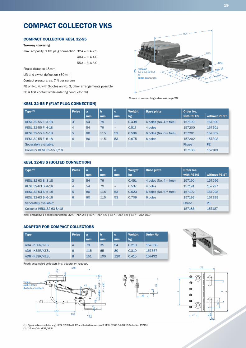
(1) Types to be completed e. g. KESL 32/63 with PE and bolted connection R KESL 32-63 S-4-18 HS Order No. 157191.(2) 25 at AD4 - KESR/KESL
max. ampacity: 1 bolted connection 32 A – AEA 2,5 | 40 A – AEA 4,0 | 55 A – AEA 6,0 | 63 A – AEA 10,0
Ready assembled collectors incl. adapter on request.
COMPACT COLLECTOR VKS
COMPACT COLLECTOR KESL 32-55Two-way conveying
max. ampacity: 1 flat plug connection 32 A – FLA 2,5
40 A – FLA 4,0
55 A – FLA 6,0
Phase distance 18 mm
Lift and swivel deflection ±30 mm
Contact pressure: ca. 7 N per carbon
PE on No. 4, with 3-poles on No. 3, other arrangements possible
PE is first contact while entering conductor rail
KESL 32-55 F (FLAT PLUG CONNECTION)
KESL 32-63 S (BOLTED CONNECTION)
ADAPTOR FOR COMPACT COLLECTORS
Type (1) Poles a b c Weight Base plate Order No.mm mm mm kg with PE HS without PE ST
KESL 32-55 F- 3-18 3 54 79 – 0.438 4 poles (No. 4 = free) 157199 157300
KESL 32-55 F- 4-18 4 54 79 – 0.517 4 poles 157200 157301
KESL 32-55 F- 5-18 5 80 115 53 0.596 6 poles (No. 6 = free) 157201 157302
KESL 32-55 F- 6-18 6 80 115 53 0.675 6 poles 157202 157303
Separately available: Phase PE
Collector KESL 32-55 F/18 157188 157189
Type (1) Poles a b c Weight Base plate Order No.mm mm mm kg with PE HS without PE ST
KESL 32-63 S- 3-18 3 54 79 – 0.451 4 poles (No. 4 = free) 157190 157296
KESL 32-63 S- 4-18 4 54 79 – 0.537 4 poles 157191 157297
KESL 32-63 S- 5-18 5 80 115 53 0.623 6 poles (No. 6 = free) 157192 157298
KESL 32-63 S- 6-18 6 80 115 53 0.709 6 poles 157193 157299
Separately available: Phase PE
Collector KESL 32-63 S/18 157186 157187
Type Poles a b c Weight Order No.mm mm mm kg
AD4 - KESR/KESL 4 79 35 54 0.210 157368
AD6 - KESR/KESL 6 115 65 80 0.310 157367
AD8 - KESR/KESL 8 151 100 120 0.410 157432
ca15
b7 42
15
72
max. 12
DF4
RF3
224
105
123456
Flat plug6,3 x 0,8 for FLAorbolted connection
Choice of connecting cable see page 20
76145
4510
542
170138
14
3
Inst
alla
tion
heig
ht =
150
Torqueeach 1,2 Nm(bolted connection)
Lift
= ±3
0
c
27 1114
30( ²)
b a
76
45
36
3

20
ACCESSORIES FOR COLLECTOR VKS
CONNECTING CABLE FLAhigh flexible for collectors with flat plug connection
(Arrangement to different collector types according to pages 18 and 19.)
Operating conditions −15°C bis 70°C
L = 1 m with flat plug 6.3 x 0.8
Longer connection cables available.
CONNECTING CABLE AEAhigh flexible for collectors with Bolted connection
(Arrangement to different collector types according to pages 18 and 19.)
Operating conditions −15°C bis 70°C
L = 1 m with wire ferrules
Longer connection cables available.
TOWING ARMfor current collectors
KSTU 30/55 see page 15
for control collectors
KSTU 30/55 see page 15
Type Weight kg Order No.
UMAS 12 HS-B 0.600 152232
Type Weight kg Order No.
UMAS 12 ST 0.600 152234
Type Order No.Cross section
Outer-Ø Wgt. Phase PE green/
mm2 mm kg black yellow
AEA 2,5 2.50 4.00 0.038 143080 143079
AEA 4,0 4.00 6.00 0.063 143078 143077
AEA 6,0 6.00 7.00 0.085 143076 143075
AEA 10,0 10.00 8.50 0.160 143074 143073
Type Order No.Cross section
Outer-Ø Wgt. Phase PE green/
mm2 mm kg black yellow
FLA 2,5 2.50 4.00 0.080 165049 165050
FLA 4 4.00 6.00 0.100 165051 165052
FLA 6 6.00 7.00 0.150 166368 166369
Table 1 Table 2
65
1862
624
170
3090
30
15
12for ground collector
slotted hole11 x 30
40 mmwide
65
4
170
3090
30
15
12
slotted hole11 x 30
40 mmwide
Collector with PE Collector without PE

21
(1) 18 mm wide
BRUSHES
SPARE PARTS FOR COLLECTORS VKS
KMK 30-55 PH KMK 30-55 PE
KMKU 25/18(1) MK 55, MK 63
Type for collectors Thickness of brush RH mm Weight kg Order No.
KMK 30-55 PH KSTU 30-55 4.40 mm 4.00 0.031 154440
KMK 30-55 PE KSTU 30-55 4.40 mm 4.00 0.034 154453
KMKU 25/18 KSFU 25 4.20 mm 3.50 0.035 155002
MK 55 F/18 KESR 32-55 F, KESL 32-55 F 4.20 mm 3.50 0.044 157308
MK 63 S/18 KESR 32-55 S, KESL 32-63 S 4.20 mm 3.50 0.053 157309
Dimension RH = allowed rest height
1010
RHRH
75
60
75
60
PE-identifi cation
1010
RHRH
75
60
75
60
PE-identifi cation
23
66
50
10
RH
2376
60
10
RH51

22
SPARE PARTS VKS
Type Order No.
Joint cap for VKS 3 152012
Joint cap for VKS 4 152013
Joint cap for VKS 5 und 6 152014
Plug-in connector (1 pole, copper) for VKS … / 10-100 A 153803
Plug-in connector (1 pole, copper) for VKS … /120-140 A 152672
Insulating piece for sectionalizing (1 pole) VSTS 1/63 L 156934
Insulating piece for sectionalizing (1 pole) VSTS 1/100 L 150419
Insulating piece for sectionalizing (1 pole) VSTS 1/120 L 151669
Insulating piece for sectionalizing (1 pole) VSTS 1/140 L 156336
Feed terminal, (1 pole) for line feed VNS 151774
Feed terminal, (1 pole) for line feed VLS 153603
SPRINGS
Pressure spring DF Tension spring RF
Type for collectors Smm
Dmm
Lmm
Order No.
DF 2 KSFU25, KESR 32-55 0.90 7.70 43.00 153848
RF 3 KSFU 25, KESR 32-55, KESL 32-63 0.40 4.40 31.00 153849
DF 4 KESL 32-63 1.10 6.40 41.00 157312
SPARE PARTS
S
D
L
S
D
L

23
COLLECTOR KSTU 30-55
SPARE PARTS FOR COLLECTORS VKS
Type Order No. Weight kg Order No.
1 Brush Phase 0.031 154440
2 Brush PE 0.031 154453
3 Collector arm KSTU, complete Phase 0.083 152275
4 Collector arm KSTU, complete PE 0.083 152276
5 Cover cap Phase (black) 0.002 152291
6 Cover cap PE (green) 0.002 152292
7 Distance spacer for KSTU 30-55 0.003 152293
8 Connecting cable RKA 2,5 PH, 2 m long Phase 0.150 154447
Connecting cable RKA 2,5 PE, 2 m long PE 0.150 154448
8 Connecting cable RKA 6 PH, 2 m long Phase 0.260 154449
Connecting cable RKA 6 PE, 2 m long PE 0.260 154450
9 Connecting screw 0.002 152658
1
7
8
2
35
9
6
4

24
max. 6
M8
377
74
PEL3L2L1N10 10 1010
6,5
14,5
21
max. 6
M8
37 7
74
PE
L3
L2
L1
N
1010
1010
6,5
14,5 21
(1) Curves with less than 2000 mm radius will be factory prepared with a 100 mm straight section on both ends – for easy connection. Horizontal curves with more than 90 degrees should be divided in two or more sections.
STANDARD SECTIONS VKL
SECTIONSStandard length 4 m
Support spacing: 1000 mm
Max. system length: 100 m
HS = with PE
SS = without PE
Type Poles max. continuous current A at 35°C
Voltage rating V
Voltage drop per 100 m at full rating V
Copper cross section CU mm2
Weight kg / m
Order No.
VKL 3/30 HS 3 30 400 10.3 9 1.104 28119•
VKL 3/30 SS 3 30 400 10.3 9 1.104 28120•
VKL 4/30 HS 4 30 400 10.3 9 1.180 28121•
VKL 4/30 SS 4 30 400 10.3 9 1.180 28122•
VKL 5/30 HS 5 30 400 10.3 9 1.256 28123•
VKL 5/30 SS 5 30 400 10.3 9 1.256 28124•
lateral suspended
• Suffix types e. g. 2 m VKL 4/30 with PE R VKL 4/30 −2 HS Order No. 281212 Shorter sections are made up from the next larger standard length.
CURVED SECTIONS(1)
max. L = 3.60 m, support spacing: ~ 500 mm
according to your layout drawing
Horizontal curve, right = web outsideOutside curve, lateral = conductors outside (not shown)
Rmin mm
Surcharge Order No. VKL
Horizontal curve, right 600 280510
Horizontal curve, left 600 280100
Inside curve, lateral 600 280520
Outside curve, lateral 400 280090
5-po
les
4-po
les
3-po
les
5-po
les
4-po
les
3-po
les
HS with PE SS without PE
PE PE PE 1 1 1
L3 L3 2 2
L2 L2 L 3 3 3
L1 L1 4 4
N N 5 5
Rmin
Rmin Rmininside curve: outside curve:
left side
right side
Web

25
85
(1) The line feeds come ready assembled on 1 m conductor rail sections. Cable by others.(2) Terminal markings see page 24.(3) Suffix types e. g. VLE 3/30 with PE R VLE 3/30 HS Order No. 281325.
ACCESSORIES FOR VKL
JOINT MATERIAL END CAPsuitable for left hand and right hand installation
FIXPOINT HANGER SLIDING HANGER
CONDUCTOR DEAD SECTIONfor control signals(2)
Please indicate where and which conductors are to be interrupted.
LINE FEED(1)
for direct cable connection
max. cable outer – Ø 16.5 mm
max. cable-cross-section 4 mm2, terminal bolt M 4
torque = 1.2 Nm
Connecting cable has to be provided by customer.
Type(3) A Weight kg
Order No. (with PE) HS
Order No. (without PE) SS
VLE 3/30 30 1.740 281325 281326
VLE 4/30 30 1.900 281327 281328
VLE 5/30 30 2.065 281329 281330
Type Order No.
VST 1 280200
VST 2 280210
VST 3 280220
VST 4 280230
VST 5 280240
Type Weight kg Order No.
VEP 0.053 281470
Type Weight kg Order No.
VA 0.050 281438
Type Weight kg Order No.
VE 0.040 280160
Type Poles Weight kg Order No.
LV 3 3 0.082 281250
LV 4 4 0.084 281251
LV 5 5 0.086 281252
30
500
500
170
19
48
16
M 8
21
30
16
M 8
21
30

26
(1) Feed is mounted on 1 m sections. End feed comes loose in components. Section is to be ordered separately (see page 24).(2) Suffix types e. g. VNK 3/30 with PE R VNK 3/30 HS Order No. 281331.
ACCESSORIES VKL / KTW-SYSTEM FOR ELECTRIC TOOLS
LINE FEED((1)
with terminal box for connecting cable 4 mm2
terminal bolt M 4 – Torque = 1.2 Nm
END FEED, LOOSE(1)
Cable gland to 4 mm2
Installation left or right possible for power and control
KTW / V with type VKL
VAHLE KTW / V-SYSTEMThese systems consist of a mounting rail with carrier wagon for holding the power tools and a plastic
conductor rail for the power supply for tools. The wagon is supplied with a mounting plate on which
electrical plugs, automatic circuit breakers or other electrical components can be mounted by the
customer. The current collector trolley is mechanically connected to the current collector by a joint. The
support rail and conductor rail are attached to a common suspension bracket, which can also be used
for suspension of the entire system. Please ask for our detailed documentation.
Type(2) Ampa- Weight Order No. Order No.city kg (with PE) (without PE)A HS SS
VNK 3/30 30 1.750 281331 281332
VNK 4/30 30 1.950 281333 281334
VNK 5/30 30 2.100 281335 281336
Type Ampacity A
Weight kg
Order No.
VEK 3-5 30 0.140 281436
TOW ARM
Type Weight kg
Order No.
VM for single collectors 0.190 280310
AM for double collectors (2 x VSR) 0.225 280640
75
5012,5
37
12030
8,5
Ø10
30
20
30148
27
Ø8,5
52
Ø10
45
115 115
500
500
70
St-M 32
78
78
52
St-M 25 x 1,5
Web
Section
CURRENT COLLECTOR VSRfor straight and curved runs
Travelling speed: 60 m/min. in curves
120 m/min. for straight runs
Carbon brushes not replacable.
connecting cable: 1.5 mm2 (1 m long)
Type(2) Ampa- Poles Weight Order No. Order No.city kg (with PE) (without PE)A HS ST
VSR 3/10 10 3 0.330 280250 281172
VSR 4/10 10 4 0.360 280260 281171
VSR 5/10 10 5 0.420 280270 281189
31
52
86
PE

27
max
.37
3230
min.50
D
L 70
ca.30
624 36
,515
18
50
624
36,515
18
70
624
36,515
18
45
X
max
.48
32
30
min.50
D
L 70
624
36,515
18
50
624
36,515
18
70
624
36,515
18
45
X
L L
B
2128
,542
6
10
50L
2128
,542
6
10
50L
Claw suitablefor D = 6 to 16 mm
VKS 4-poles
VKS 6-poles
VKS 4-poles
VKS 6-poles
VKS 3-poles
VKS 3-poles
Claw suitablefor D = 15 to 25 mm
Attachmentbracket
Attachmentbracket
Attachmentbracket
Attachmentbracket
Attachmentbracket
Attachmentbracket
(1) Please complete types e.g. for VKS R HKVKS 200 for VKL R HKVKL 200
BRACKETS AND SNAP-ON BRACKETS VKS, VKL
ATTENTION!Make sure that hoist wheels of monorail systems have enough clearance.
C-rail of HKV is identical to type S1 for cable carriers (catalog 8a).
Hangers to be ordered separately.
The corresponding beam width (Bmax) could be enlarged by a reduction
of X.
SNAP-ON BRACKETSSnap-on brackets facilitate installation of conductor system on flat flange
beams PE-, PB-, PBI- and PBv. They are adjustable to suit beam
flange dimensions (tg) of up to 43 mm.
Hangers for conductor system to be ordered separately.
Type(1) x mm
L mm
Bmax mm
Weight kg
Order No. VKS
Order No. VKL
HK … 200 200 300 90 0.920 150600 280550
HK … 250 250 350 180 0.970 150610 280560
HK … 300 300 400 230 1.020 150620 280570
HK … 400 400 500 230 1.120 150630 280580
HK … 500 500 600 230 1.220 150640 280590
HK … 600 600 700 230 1.320 150650 280600
HK … 700 700 800 230 1.420 150660 280610
HK … 750 750 850 230 1.470 150670 280620
HK … 800 800 900 230 1.560 150680 280630
Type AKL
Beam flange tg/mm 8-13 14-19 20-25 26-31 32-37 38-43
Weight/kg 0.184
Order No. 151925
max
.37
32
30
min.50
D
L 70
ca.30
624 36
,515
18
50
624
36,515
18
70
624
36,515
18
45
X
max
.48
32
30
min.50
D
L 70
624
36,515
18
506
2436
,515
18
70
624
36,515
18
45
X
L L
B
2128
,542
6
10
50L
2128
,542
6
10
50L
Claw suitablefor D = 6 to 16 mm
VKS 4-poles
VKS 6-poles
VKS 4-poles
VKS 6-poles
VKS 3-poles
VKS 3-poles
Claw suitablefor D = 15 to 25 mm
Attachmentbracket
Attachmentbracket
Attachmentbracket
Attachmentbracket
Attachmentbracket
Attachmentbracket
15tg
15tg
6880
tg
91
15
90
15tg
15tg
6880
tg
91
15
90
AKL with VKS 3 AKL with VKS 4AKL with VKL AKL with VKS 6

28
7-POLE VKS SYSTEM FOR HRL
This system combines a VKS 4-pole and VKS 3-pole conductor rail in a common hanger clamp.
Possible fixing methods are shown below. All available VKS 4-pole and VKS 3-pole conductor systems can be combined. All standard components
of VKS conductor system can be used. Restrictions apply to line feeds VNS, end feeds VEKS, transfers and towing arms (consult factory for these
components).
FIXPOINT HANGER VEPS AND SLIDING HANGER VAS
Type Wgt. kg
Order No.
VEPS 4/3 SF M 6 x 16 0.100 156114
VAS 4/3 SF M 6 x 16 0.080 156115
Type Wgt. kg
Order No.
VEPS 4/3 GP M 6 0.121 156116
VAS 4/3 GP M 6 0.101 156117
Type Wgt. kg
Order No.
VEPS 4/3 M 6 x 35 0.119 156772
VAS 4/3 M 6 x 35 0.099 156089
SYSTEM OVERVIEW
1
2
3
4
5
6
1 Fixpoint hanger
2 Joint material
3 End caps
4 Collector bracket
5 Current collector
6 Sliding hanger
89
17
73
40
45,5
35,5
81
162
21,5
22,5 989
15
73
40
45,5
35,5
81
162
21,5
22,5
M6
45,5
35,5
81
162
21,5
12,5
M6
22,5
25-35
56,5
40,5
65
32,5
32,5 2-10
S2 rail S2 rail
89
17
73
40
45,5
35,5
81
162
21,5
22,5 9
89
15
73
40
45,5
35,5
81
162
21,5
22,5
M6
45,5
35,5
81
162
21,5
12,5
M6
22,5
25-35
56,5
40,5
65
32,5
32,5 2-10
S2 rail S2 rail
89
17
73
40
45,5
35,5
81
162
21,5
22,5 9
89
15
73
40
45,5
35,5
81
162
21,5
22,5
M6
45,5
35,5
81
162
21,5
12,5
M6
22,5
25-35
56,5
40,5
65
32,5
32,5 2-10
S2 rail S2 rail

29
(1) Layout symbols see page 7
EXAMPLES FOR ORDERING VKS AND VKL
STRAIGHT TRACK WITH END FEED(1)
12 m VKS 3/100; VKL 3/30 HS
Layout VKS Layout VKL
CURVED TRACK WITH END FEED(1)
14.142 m VKL 5/30 HS
Qty Description Type Order No. Qty Type Order No.
2 Conductor rail, 4 m long VKS 3/100-4 HS 153904 2 VKL 3/30-4 HS 281194
1 Conductor rail, 3 m long VKS 3/100-3 HS 153903 1 VKL 3/30-3 HS 281193
1 Conductor rail, 1 m long VKS 3/100-1 HS 153901 1 VKL 3/30-1 HS 281191
3 Joint material SVN 3/63-100 156533 3 LV 3 281250
4 Fixpoint hanger VEPS 3 153070 1 VEP 281470
10 Sliding hangers VAS 3 153060 10 VA 281438
1 End cap VES 3 153080 1 VE 280160
1 End feed VEKS 3/10-120 L 156422 1 VEK 3-5 281436
1 Collector KESR 32-55F-3-18 HS 157285 1 VSR 3/10 HS 280250
– Tow arm – – 1 VM 280310
14 Support bracket HKVKS 300 150620 14 HKVKL 300 280570
Qty Description Type Order No.
2 Conductor rail, 4 m long VKL 5/30-4 HS 281234
1 Conductor rail, 2 m long VKL 5/30-2 HS 281232
1 Conductor rail, 4 m long for inside curve lateral 90°; R = 2000 mm; L = 3.142 m
VKL 5/30-4 HS 281234
1 Bending surcharge inside curve 280520
4 Joint material LV 5 281252
1 Fixpoint hanger VEP 281470
15 Sliding hangers VA 281438
1 End cap VE 280160
1 End feed, 1 m long VEK 3-5 281436
1 Collector VSR 5/10 HS 280270
1 Tow arm VM 280310
L
R
1000 4000
4000
2000
R 2000Copper conductorsthis side
L = left sideR = right side
RL
1000 4000 4000 3000
12000
Copper conductorsL = left side | R = right side
RL
1000 4000 4000 3000
12000
Copper conductorsL = left side | R = right side

30
(1) Layout symbols see page 7.
R
4000
100
3173
10010002300
100
3142
100
985
33
1200
1170
1985
1000
1515
1515
L
L
R
R
R
R 2000
R 2000
1556
100585
15
L
R 2000
L
1200
100
1571100
1000
2985
15
R 2020
1
2
34
5
6
7
8
9
10
11
12
13 14
3
Copper conductors this side
L = left sideR = right side
EXAMPLE FOR ORDERING VKS
Qty Description Type Order No. Position
1 Conductor rail, 4 m long VKS 6/63-4 HS 154194 1
2 Conductor rail, 3 m longcut to: 1 x 2.985 m
1 x 2.300 m
VKS 6/63-3 HS 154193 12 4
3 Conductor rail, 2 m longcut to: 1 x 1.985 m
1 x 1.200 m1 x 1.170 m
VKS 6/63-2 HS 154192 8 14 7
3 Conductor rail, 1 m long VKS 6/63-1HS 154191 3 9
2 Conductor rail, 1 m longcut to: 1 x 0.985 m
1 x 0.585 m
VKS 6/63-1 HS 154191 6 11
2 Conductor rail, 4 m long1 x for outside curve90°; R = 2020 mm; L = 3.373 m1 x for inside curve90°; R = 2000 mm; L = 3.342 m
VKS 6/63-4 HS 154194 2 5
2 Conductor rail, 2 m long1 x for inside curve~ 45°; R = 2000 mm; L = 1.656 m1 x for inside curve45°; R = 2000 mm; L = 1.771 m
VKS 6/63-2 HS 154192 10 13
1 Bending surcharge (outside curve) 152100
3 Bending surcharge (inside curve) 153722
10 Joint material SVN 6/63-100 156539
16 Fixpoint hangers VEPS 6 152120
22 Sliding hangers VAS 6 152130
3 End caps on above position. 1, 9, 14 VES 6-M 152021
2 Line feeds installed on position 3, 7, 9, 11 VLS 6/63 156945
3 Transfer guides, left installed on Pos. 6, 7, 11 VU 6 S-M 153801
4 Transfer guides, right installed on Pos. 7, 8, 10, 12 VU 6 S-M 153802
1 Compact collector, Ground on No. 3 KESR 32-55S-6-18 HS 157223
CURVED TRACK WITH SWITCH (LATERAL MOUNTING)(1)
27.857 m VKS 6/63 HS

31
(1) For curved tracks, conductor system with isolating sections etc., we require sketches to enable us to prepare a quotation(2) Use: K for squirrel cage motor, S for slipring motor, F for frequency controlled motor We reserve all rights to make alterations in the interests of further development Please copy and fill in the questionnaire.
QUESTIONNAIRECompany: ___________________________________________________ Date: _______________________________________________________
Fon: ________________________________________________________ Fax: ________________________________________________________
E-mail: ______________________________________________________ Internet: _____________________________________________________
1. Number of conductor system installations: ____________________________________________________________________________________
2. Type of equipment to be powered: ____________________________________________________________________________________________
3. Operating voltage: ________ Volt Frequency: ________ Hz
Three-phase voltage AC voltage DC voltage
4. Track length: _____________________________________________________________________________________________________________
5. Number of conductors: ________ neutral: ________ control: ________ ground: ________
6. Mounted position of conductor system:
Conductor system pendant, collector cable facing to the bottom Conductor system pendant, lateral payout of conductor cable(1)
Support distance ________ m (max. 2 m) Other: __________________________________________________________________________
7. Number of consumers per system: ___________________________________________________________________________________________
8. Indoor system Outdoor system
9. Other operating conditions (humidity, dust, chemical influence, etc.) _______________________________________________________________
10. Ambient temperature: ________°C min. ________°C max.
11. Hall expansion joints ________ pieces ________ expansion max.
12. Position and number of feeding points(1): ______________________________________________________________________________________
13. Position and number of isolating sections (e. g. for maintenance)(1): ________________________________________________________________
14. How will the conductor be arranged?(1): _______________________________________________________________________________________
15. Brackets required: Yes No c/c distance beam/conductor system: ________________________________________________________
16. Travel speed: ________ m/min. in curves: ________ m/min. at transfers: ________ m/min.
17. Max. voltage drop from the conductor system feed point to the consumer considering starting current. ___________________________________
18. Power consumption of the individual consumer loads: ___________________________________________________________________________
Motor dataCrane 1 Crane 2
Power kW
Nominal current Starting current
Type of motors (2)
Power kW
Nominal current Starting current
Type of motors (2)
A cos ϕN % duty A cos ϕA A cos ϕN % duty A cos ϕA
Hoist motors
Auxiliary hoist
Long travel
Cross travel
Mark with * those motors which can run simultaneously.
Mark with Δ those motors which can start up simultaneously.
Further remarks: _____________________________________________________________________________________________________________
____________________________________________________________________________________________________________________________
Signature:

Paul Vahle GmbH & Co. KGWesticker Str. 52
59174 KamenGermany
Tel.: +49 2307 704-0Fax: +49 2307 704-444
www.vahle.com
W11
0012
2/00
/en
| 0
| Re
v.02
| 0
2/19
| E
rrors
and
tech
nica
l mod
ifica
tions
sub
ject
to c
hang
e.