compact fiber optic patch panel - barr-thorp · compact size allows minimum space requirements ......
TRANSCRIPT
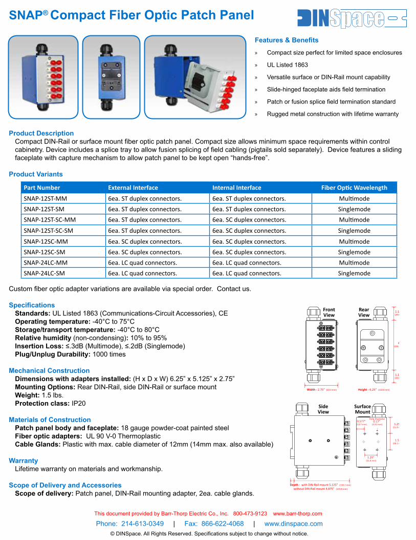
SNAP® Compact Fiber Optic Patch Panel
Product DescriptionCompact DIN-Rail or surface mount fiber optic patch panel. Compact size allows minimum space requirements within control cabinetry. Device includes a splice tray to allow fusion splicing of field cabling (pigtails sold separately). Device features a sliding faceplate with capture mechanism to allow patch panel to be kept open “hands-free”.
Product Variants
Custom fiber optic adapter variations are available via special order. Contact us.
SpecificationsStandards: UL Listed 1863 (Communications-Circuit Accessories), CEOperating temperature: -40°C to 75°CStorage/transport temperature: -40°C to 80°CRelative humidity (non-condensing): 10% to 95%Insertion Loss: ≤.3dB (Multimode), ≤.2dB (Singlemode)Plug/Unplug Durability: 1000 times
Mechanical Construction Dimensions with adapters installed: (H x D x W) 6.25” x 5.125” x 2.75”Mounting Options: Rear DIN-Rail, side DIN-Rail or surface mountWeight: 1.5 lbs. Protection class: IP20
Materials of ConstructionPatch panel body and faceplate: 18 gauge powder-coat painted steelFiber optic adapters: UL 90 V-0 ThermoplasticCable Glands: Plastic with max. cable diameter of 12mm (14mm max. also available)
WarrantyLifetime warranty on materials and workmanship.
Scope of Delivery and AccessoriesScope of delivery: Patch panel, DIN-Rail mounting adapter, 2ea. cable glands.
Part Number External Interface Internal Interface Fiber Optic Wavelength
SNAP-12ST-MM 6ea. ST duplex connectors. 6ea. ST duplex connectors. MultimodeSNAP-12ST-SM 6ea. ST duplex connectors. 6ea. ST duplex connectors. SinglemodeSNAP-12ST-SC-MM 6ea. ST duplex connectors. 6ea. SC duplex connectors. Multimode
SNAP-12ST-SC-SM 6ea. ST duplex connectors. 6ea. SC duplex connectors. Singlemode
SNAP-12SC-MM 6ea. SC duplex connectors. 6ea. SC duplex connectors. MultimodeSNAP-12SC-SM 6ea. SC duplex connectors. 6ea. SC duplex connectors. SinglemodeSNAP-24LC-MM 6ea. LC quad connectors. 6ea. LC quad connectors. MultimodeSNAP-24LC-SM 6ea. LC quad connectors. 6ea. LC quad connectors. Singlemode
Features & Benefits
» Compact size perfect for limited space enclosures
» UL Listed 1863
» Versatile surface or DIN-Rail mount capability
» Slide-hinged faceplate aids field termination
» Patch or fusion splice field termination standard
» Rugged metal construction with lifetime warranty
Phone: 214-613-0349 | Fax: 866-622-4068 | www.dinspace.com© DINSpace. All Rights Reserved. Specifications subject to change without notice.
FrontView
RearView
SideView
Width - 2.75” (69.9 mm) Height - 6.25” (158.8 mm)
Depth - with DIN-Rail mount 5.125” (130.2 mm)
without DIN-Rail mount 4.875” (123.8 mm)
4” (101.6 mm)
1.125” (28.6 mm)
1.125” (28.6 mm)
1.25” (31.8 mm)
1.5” (38.1 mm)
1.25” (31.8 mm)
0.577” (14.7 mm)
Hole Diameter0.17”
(4.32 mm)
SurfaceMount
This document provided by Barr-Thorp Electric Co., Inc. 800-473-9123 www.barr-thorp.com
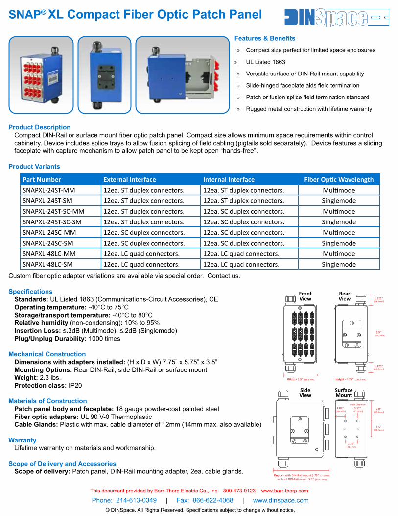
SNAP® XL Compact Fiber Optic Patch Panel
Product DescriptionCompact DIN-Rail or surface mount fiber optic patch panel. Compact size allows minimum space requirements within control cabinetry. Device includes splice trays to allow fusion splicing of field cabling (pigtails sold separately). Device features a sliding faceplate with capture mechanism to allow patch panel to be kept open “hands-free”.
Product Variants
Custom fiber optic adapter variations are available via special order. Contact us.
SpecificationsStandards: UL Listed 1863 (Communications-Circuit Accessories), CEOperating temperature: -40°C to 75°CStorage/transport temperature: -40°C to 80°CRelative humidity (non-condensing): 10% to 95%Insertion Loss: ≤.3dB (Multimode), ≤.2dB (Singlemode)Plug/Unplug Durability: 1000 times
Mechanical Construction Dimensions with adapters installed: (H x D x W) 7.75” x 5.75” x 3.5”Mounting Options: Rear DIN-Rail, side DIN-Rail or surface mountWeight: 2.3 lbs. Protection class: IP20
Materials of ConstructionPatch panel body and faceplate: 18 gauge powder-coat painted steelFiber optic adapters: UL 90 V-0 ThermoplasticCable Glands: Plastic with max. cable diameter of 12mm (14mm max. also available)
WarrantyLifetime warranty on materials and workmanship.
Scope of Delivery and AccessoriesScope of delivery: Patch panel, DIN-Rail mounting adapter, 2ea. cable glands.
Part Number External Interface Internal Interface Fiber Optic WavelengthSNAPXL-24ST-MM 12ea. ST duplex connectors. 12ea. ST duplex connectors. MultimodeSNAPXL-24ST-SM 12ea. ST duplex connectors. 12ea. ST duplex connectors. SinglemodeSNAPXL-24ST-SC-MM 12ea. ST duplex connectors. 12ea. SC duplex connectors. MultimodeSNAPXL-24ST-SC-SM 12ea. ST duplex connectors. 12ea. SC duplex connectors. SinglemodeSNAPXL-24SC-MM 12ea. SC duplex connectors. 12ea. SC duplex connectors. MultimodeSNAPXL-24SC-SM 12ea. SC duplex connectors. 12ea. SC duplex connectors. SinglemodeSNAPXL-48LC-MM 12ea. LC quad connectors. 12ea. LC quad connectors. MultimodeSNAPXL-48LC-SM 12ea. LC quad connectors. 12ea. LC quad connectors. Singlemode
Features & Benefits
» Compact size perfect for limited space enclosures
» UL Listed 1863
» Versatile surface or DIN-Rail mount capability
» Slide-hinged faceplate aids field termination
» Patch or fusion splice field termination standard
» Rugged metal construction with lifetime warranty
Phone: 214-613-0349 | Fax: 866-622-4068 | www.dinspace.com© DINSpace. All Rights Reserved. Specifications subject to change without notice.
RearView
SideView
Width - 3.5” (88.9 mm) Height - 7.75” (196.9 mm)
5.5” (139.7 mm)
1.125” (28.6 mm)
1.125” (28.6 mm)
FrontView
Depth - with DIN-Rail mount 5.75” (146 mm)
without DIN-Rail mount 5.5” (139.7 mm)
SurfaceMount
2.0” (50.8 mm)
1.5” (38.1 mm)
1.25” (31.8 mm)
1.04” (26.4 mm)
Hole Diameter0.17”
(4.32 mm)
This document provided by Barr-Thorp Electric Co., Inc. 800-473-9123 www.barr-thorp.com
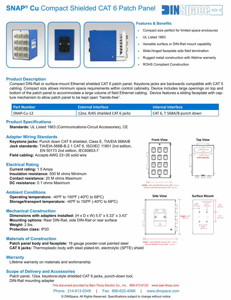
SNAP® Cu Compact Shielded CAT 6 Patch Panel
Product DescriptionCompact DIN-Rail or surface-mount Ethernet shielded CAT 6 patch panel. Keystone jacks are backwards compatible with CAT 5 cabling. Compact size allows minimum space requirements within control cabinetry. Device includes large openings on top and bottom of the patch panel to accommodate a large volume of field Ethernet cabling. Device features a sliding faceplate with cap-ture mechanism to allow patch panel to be kept open “hands-free”.
Product SpecificationsStandards: UL Listed 1863 (Communications-Circuit Accessories), CE
Adapter Wiring StandardsKeystone jacks: Punch down CAT 6 shielded, Class E, TIA/EIA 568A/BJack standards: TIA/EIA-568B-B.2.1 CAT 6, ISO/IEC 11801 2nd edition, EN 50173 2nd edition, IEC60603-7Field cabling: Accepts AWG 23~26 solid wire
Electrical RatingCurrent rating: 1.5 AmpsInsulation resistance: 500 M ohms MinimumContact resistance: 20 M ohms MaximumDC resistance: 0.1 ohms Maximum
Ambient ConditionsOperating temperature: -40ºF to 150ºF (-40ºC to 68ºC)Storage/transport temperature: -40ºF to 150ºF (-40ºC to 68ºC)
Mechanical Construction Dimensions with adapters installed: (H x D x W) 5.5” x 5.33” x 3.43”Mounting options: Rear DIN-Rail, side DIN-Rail or rear surfaceWeight: 2 lbs. Protection class: IP20
Materials of ConstructionPatch panel body and faceplate: 18 gauge powder-coat painted steelCAT 6 jacks: Thermoplastic body with steel plated-tin, electrolytic (SPTE) shield
WarrantyLifetime warranty on materials and workmanship
Scope of Delivery and AccessoriesPatch panel, 12ea. keystone-style shielded CAT 6 jacks, punch-down tool, DIN-Rail mounting adapter
Part Number External Interface Internal InterfaceSNAP-Cu-12 12ea. RJ45 shielded CAT 6 jacks CAT 6, T 568A/B punch down
Features & Benefits
» Compact size perfect for limited space enclosures
» UL Listed 1863
» Versatile surface or DIN-Rail mount capability
» Slide-hinged faceplate aids field termination
» Rugged metal construction with lifetime warranty
» ROHS Compliant Construction
Phone: 214-613-0349 | Fax: 866-622-4068 | www.dinspace.com© DINSpace. All Rights Reserved. Specifications subject to change without notice.
Side View
Width - with side DIN-Rail mount 3.68” (93 mm)
without side DIN-Rail mount 3.43” (87 mm)
2.77” (70 mm)
0.79” (20 mm)
Top ViewFront View
Depth - with DIN-Rail mount 5.33” (135mm)
without DIN-Rail mount 5.08” (129 mm)
Height - 5.5”(140 mm)
Cable Opening
Surface Mount
2.0” (50.8 mm)
1.5” (38.1 mm)
1.04” (26.4 mm)
Hole Diameter
0.17” (4.32 mm)
1.25” (31.8 mm)
This document provided by Barr-Thorp Electric Co., Inc. 800-473-9123 www.barr-thorp.com
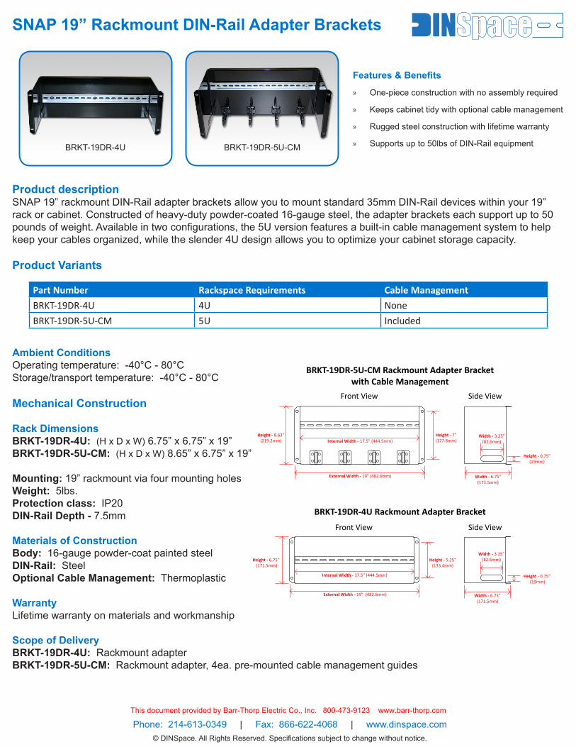
SNAP 19” Rackmount DIN-Rail Adapter Brackets
Product descriptionSNAP 19” rackmount DIN-Rail adapter brackets allow you to mount standard 35mm DIN-Rail devices within your 19” rack or cabinet. Constructed of heavy-duty powder-coated 16-gauge steel, the adapter brackets each support up to 50 pounds of weight. Available in two configurations, the 5U version features a built-in cable management system to help keep your cables organized, while the slender 4U design allows you to optimize your cabinet storage capacity.
Product Variants
Ambient ConditionsOperating temperature: -40°C - 80°CStorage/transport temperature: -40°C - 80°C
Mechanical Construction
Rack DimensionsBRKT-19DR-4U: (H x D x W) 6.75” x 6.75” x 19”BRKT-19DR-5U-CM: (H x D x W) 8.65” x 6.75” x 19”
Mounting: 19” rackmount via four mounting holesWeight: 5lbs. Protection class: IP20DIN-Rail Depth - 7.5mm
Materials of ConstructionBody: 16-gauge powder-coat painted steelDIN-Rail: SteelOptional Cable Management: Thermoplastic
WarrantyLifetime warranty on materials and workmanship
Scope of DeliveryBRKT-19DR-4U: Rackmount adapterBRKT-19DR-5U-CM: Rackmount adapter, 4ea. pre-mounted cable management guides
Part Number Rackspace Requirements Cable Management
BRKT-19DR-4U 4U None
BRKT-19DR-5U-CM 5U Included
Features & Benefits
» One-piece construction with no assembly required
» Keeps cabinet tidy with optional cable management
» Rugged steel construction with lifetime warranty
» Supports up to 50lbs of DIN-Rail equipment
Phone: 214-613-0349 | Fax: 866-622-4068 | www.dinspace.com© DINSpace. All Rights Reserved. Specifications subject to change without notice.
BRKT-19DR-4U BRKT-19DR-5U-CM
Height - 0.75”(19mm)
Width - 3.25”(82.6mm)
Side View
Width - 6.75”(171.5mm)
Internal Width - 17.5” (444.5mm)
BRKT-19DR-5U-CM Rackmount Adapter Bracketwith Cable Management
BRKT-19DR-4U Rackmount Adapter Bracket
Internal Width - 17.5” (444.5mm)
Front View
Height - 7”(177.8mm)
External Width - 19” (482.6mm)
Height - 8.63”(219.2mm)
Height - 0.75” (19mm)
Width - 3.25”(82.6mm)
Width - 6.75”(171.5mm)
Side ViewFront View
Height - 5.25”(133.4mm)
Height - 6.75” (171.5mm)
External Width - 19” (482.6mm)
This document provided by Barr-Thorp Electric Co., Inc. 800-473-9123 www.barr-thorp.com

Phone: 214-‐613-‐0349 | Fax: 866-‐622-‐4068 | Web: www.dinspace.com DINSpace All Rights Reserved. Specifications subject to change without notice.
Note: Pigtails Sold Individually
R30086 Splice Protections ANT 030.0094
Warranty Acc. To GBT
Description Crimp splice protection type (ANT) for single fibers. Material: sheet plate parts, inside coated with permanently elastic material. Dimensions: 1.2x3.2x30 mm (WxHxD).
Weight 0.000G
Technical Data Material Sheet metal part with permanently elastic insulation material Dimensions 1.2 x 3.2 x 30 mm Dispatch weight 0.000 Unit of dispatch weight G
This document provided by Barr-Thorp Electric Co., Inc. 800-473-9123 www.barr-thorp.com
Phone: 214-613-0349 | Fax: 866-622-4068 | Web: www.dinspace.com
16415 Addison Road, Suite 370, Addison, TX 75001 Phone: 214-613-0349 | Fax: 866-622-4068 | Web: www.dinspace.com
Lifetime Limited Warranty
DINSpace guarantees all of its standard products to be of first-class construction and
provides a lifetime warranty against any defects in material and workmanship. The
warranty does not apply to damage caused by abnormal or unreasonable use of any of
the products (including repairs or alterations other than by DINSpace technical
support). This warranty is in place of all other warranties, including warranty of fitness
for a particular purpose and warranty of merchantability and excludes any liability for
incidental or consequential damages.
Repairs
If your DINSpace product has a manufacturer’s defect covered by our warranty, we will
either repair or replace it, at our option, without charge. Please contact DINSpace
customer support to describe the issue, and if a return is deemed necessary to resolve
the issue, a Return Merchandise Authorization (RMA) number will be issued. No
returns will be accepted without an RMA number. Send to the address below. Include
your name, address, phone number and the RMA number with your return. A product
not covered by the warranty can be repaired. Note that repair costs and handling
charges may apply. If so, you will be notified prior to any service.
Address
DINSpace - Service Center
16415 Addison Road, Suite 370
Addison, TX 75001
This document provided by Barr-Thorp Electric Co., Inc. 800-473-9123 www.barr-thorp.com